j-lcd(5s protocol) from king-meter 1589857045208
TRANSCRIPT
KING-METER
USERS GUIDE
J –LCD
2
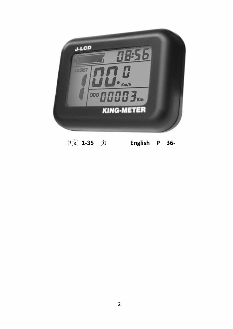
中文 1-35 页 English P 36-

I
Contents
About the User Manual ..................................................................... 1 Appearance and Size ......................................................................... 2
Material and Color .................................................................... 2 Function Summary and Button Definition ........................................ 4
Function Overview .................................................................... 4 Normal Display Area .................................................................. 5 Button Definition ....................................................................... 5
Precautions ........................................................................................ 6 Installation Instruction ...................................................................... 6 Standard Operation ........................................................................... 7
Power ON / OFF ......................................................................... 7 Display Interface ........................................................................ 7 Distance (Including single trip and ODO) .................................. 8 Speed (current speed/average speed/max speed) .................. 8 Push Cruise Control ................................................................... 9 Turn On Backlight ...................................................................... 9 PAS Level Selection .................................................................. 10 Battery Indicator...................................................................... 10 Time Display ............................................................................ 10 Error Code ............................................................................... 11
User Setting ..................................................................................... 12 Preparation before Power On ................................................. 12 General Setting ........................................................................ 12

II
Time setting: ............................................................................ 12 Backlight Brightness ........................................................ 13 Display Unit ..................................................................... 13 Single Trip Clearance ....................................................... 14 Exit Setting....................................................................... 14
Password Setting ..................................................................... 15 Password Use .................................................................. 15 Modified Password.......................................................... 16
Operation Parameter Setting .................................................. 16 Wheel Size Setting ........................................................... 17 Speed Limit Setting ......................................................... 17
Personalization ................................................................................ 18 Personalization Password Input .............................................. 18 Battery Indicator Setting ......................................................... 20 PAS Parameter Setting ............................................................. 21
PAS Level Selection .......................................................... 21 PAS Proportion Setting .................................................... 21
Current Limit Setting ............................................................... 22 PAS Sensor Setting ................................................................... 22
PAS Sensor Direction Setting ........................................... 22 PAS Sensor Sensitivity Setting ......................................... 23 PAS Sensor Proportion Parameter Setting ...................... 23
Speed Sensor Setting............................................................... 24 Throttle Function Setting ........................................................ 24
Throttle Push Cruise Control Enable Setting .................. 24 Throttle Level Enable Setting .......................................... 25
System Setting ......................................................................... 26

III
Battery Delay Time Setting.............................................. 26 Max Speed Limit Setting ................................................. 26 Push Cruise Control Enable Setting................................. 27 Push Speed Setting .......................................................... 27 Slowly Start up Setting .................................................... 28
Exit Setting ............................................................................... 28 Restore Default Setting ................................................................... 29 FAQ Answers .................................................................................... 30 Quality Warranty And Coverage ..................................................... 30 Circuit Block Diagram ...................................................................... 31 Software Version ............................................................................. 32 Attached Table 1:Definition of Error Code ................................... 32 Attached Table 2:Password Checklist ........................................... 34 Attached Table 3:Personalization Parameters Table .................... 35 Attached Table 4:PAS Proportion Default Value ............................. 37

1
About the User Manual
Dear users, To ensure better performance of your e-bike, please read through the J- LCD product introduction carefully before using it. We will use the brief words to inform you of all the details (including hardware installation, setting and normal use of the display) when using our display. Meanwhile, the introduction will also help you solve possible confusion and barriers.
2
Appearance and Size
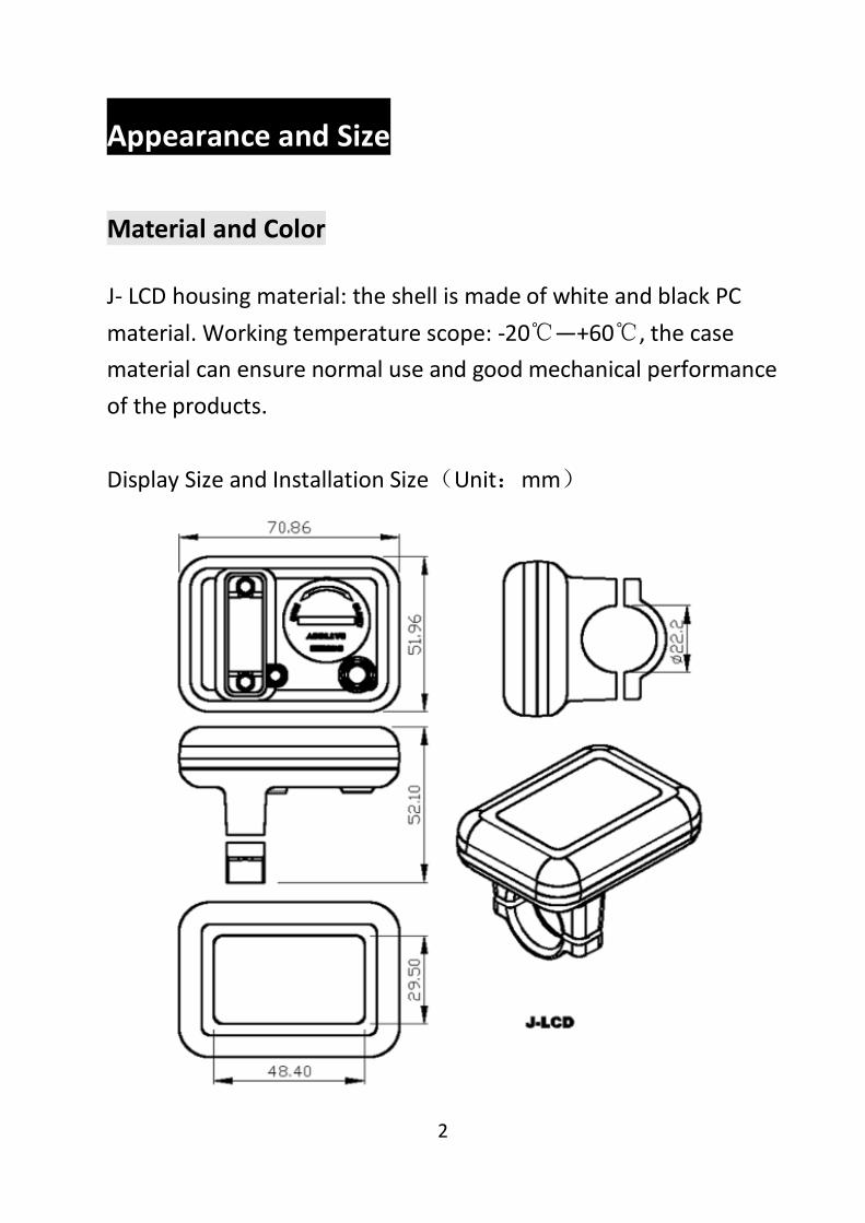
Material and Color
J- LCD housing material: the shell is made of white and black PC material. Working temperature scope: -20℃—+60℃, the case material can ensure normal use and good mechanical performance of the products. Display Size and Installation Size(Unit:mm)

3
J-LCD is equipped with special 30-button unit, the 30-button can be install on the left side or the right side of the handlebar, 30 button shape show as follows:
The 30 button is connected to the bottom lead of the J-LCD display.

4
Function Summary and Button Definition
Function Overview
The J-LCD offers you a variety of features and displays to meet the cyclists’ requirements. The contents displayed are:
◆Battery capacity ◆Real time display ◆ Speed (Including current speed, maximum speed and
average speed) ◆Distance (Including single trip and ODO) ◆Push cruise control ◆Turn on backlight ◆Error Code ◆Multiple setting parameters ◆Default parameter reset

5
Normal Display Area
J-LCD normal display area
Button Definition
In the subsequent description, the button is replaced with
【MODE】. The button is replaced with【UP】, and the
button is replaced with【DOWN】.

6
Precautions
Pay attention to safety during use, do not connect or disconnect the display while it is powered on.
The display should avoid bumps.
The display uses a film as waterproof film; please do not tear it, so as not to affect the waterproof performance of the display. Regarding the background parameter setting of the display, please do not change it at will, otherwise it will not guarantee normal riding. When the display is not working properly, it should be repaired as soon as possible.
Installation Instruction
Fix the display on the handlebar and adjust the proper angle of view. In the case that the e-bike is powered off, the connector of the display is inserted into the connector corresponding to the controller to complete the installation.

7
Standard Operation
Power ON / OFF
Hold 【MODE】 button, the display starts to work and provides the controller with working power. In the power on state, hold 【MODE】 button to turn off the power of the electric bike. In the power off state, the display no longer uses the battery's power supply, and the display's leakage current is less than 1uA.
If the e-bike is not used for more than 10 minutes, the display will shut down automatically.
Display Interface
After the display is turned on, the display shows the following interface:
8
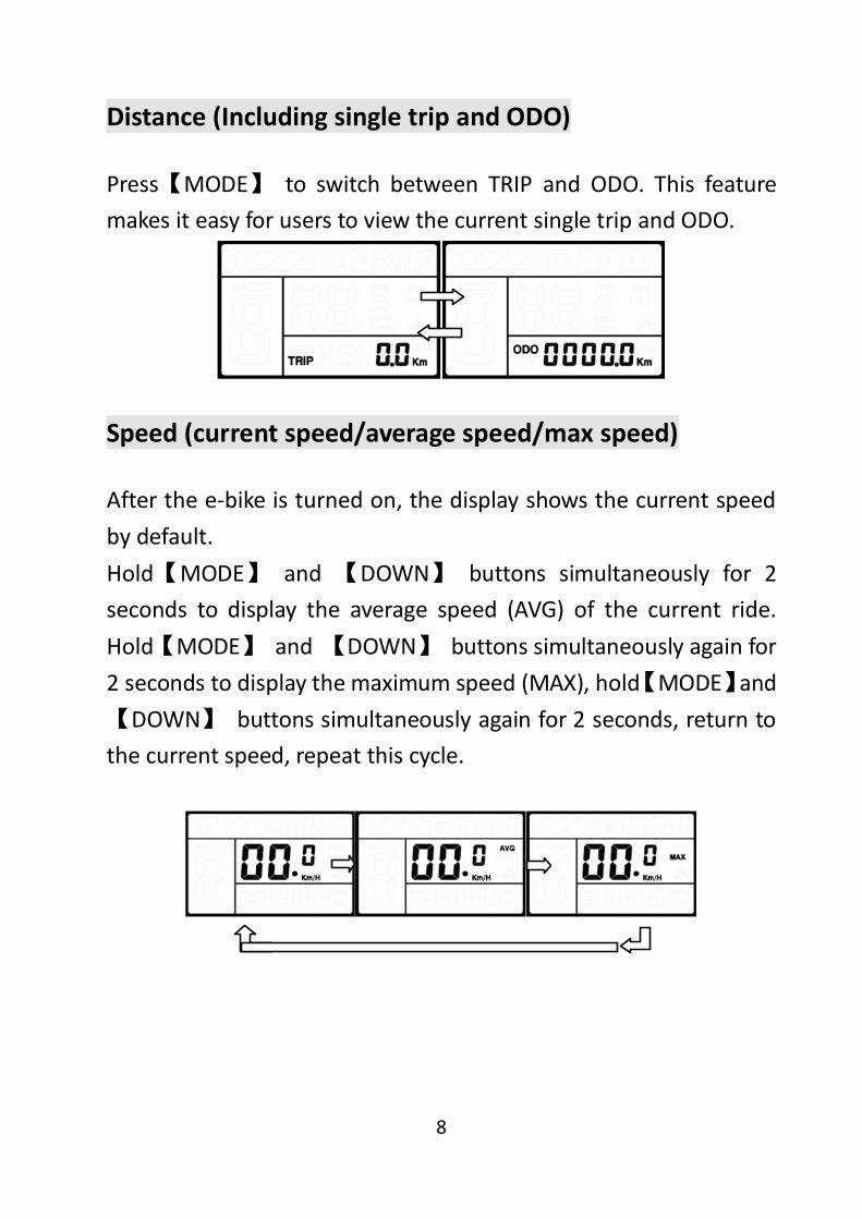
Distance (Including single trip and ODO)
Press【MODE】 to switch between TRIP and ODO. This feature makes it easy for users to view the current single trip and ODO.
Speed (current speed/average speed/max speed)
After the e-bike is turned on, the display shows the current speed by default. Hold【MODE】 and 【DOWN】 buttons simultaneously for 2 seconds to display the average speed (AVG) of the current ride. Hold【MODE】 and 【DOWN】 buttons simultaneously again for 2 seconds to display the maximum speed (MAX), hold【MODE】and 【DOWN】 buttons simultaneously again for 2 seconds, return to the current speed, repeat this cycle.

9
Push Cruise Control
Hold【DOWN】for 2 seconds, the e-bike enters the mode of power assist walk. The e-bike travels at a constant speed of 6 Km/h, WALK symbol flashes on the screen.
The power-saving function can only be used when the user pushes the e-bike. Do not use it while riding.
Turn On Backlight
Hold 【UP】 button for 2 seconds, the display’s backlight is turned on, and the controller is notified to turn on the headlights. The LCD backlight can be turned on when there is insufficient external light or driving at night. Hold【UP】 button for 2 seconds again, and the LCD backlight turns off.
。

10
PAS Level Selection
Press the 【UP】 or 【DOWN】 button to switch the PAS level of the e-bike and change the output power of the motor. The default output power range of the display is PAS 1-5, and the default level is level 1.
Battery Indicator
When the battery voltage is high, the five-segment LCD is bright. When the battery is under voltage, the outer frame of the battery flashes, indicating that the battery is seriously under-voltage and has to be charged immediately.
Flashing under-voltage
Time Display
The display can show a real-time, the display shows as following interface:

11
Error Code
When the e-bike electronic control system fails, the display will report the error code automatically. See Table 1 for the definition of the detailed error code.
The fault display interface can only be exited when the fault is eliminated. After the fault occurs, the e-bike will not be able to continue riding.

12
User Setting
Preparation before Power On
Make sure the connectors are docked firmly and turn on the e-bike power.
General Setting
Hold 【MODE】 button to start up. In the power-on state, hold 【UP】 and 【DOWN】buttons simultaneously for 2 seconds, the display enters the setting state.
Time setting:
by [UP]/[DOWN] select the hour value, press【MODE】button to confirm and enter the minute setting; select the minute value by [UP]/[DOWN], press【MODE】button to confirm and enter the next setting.
13
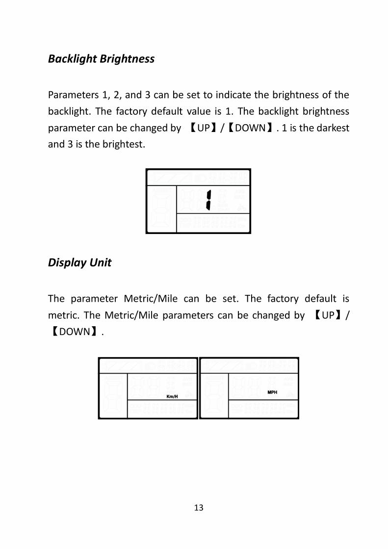
Backlight Brightness
Parameters 1, 2, and 3 can be set to indicate the brightness of the backlight. The factory default value is 1. The backlight brightness parameter can be changed by 【UP】/【DOWN】. 1 is the darkest and 3 is the brightest.
Display Unit
The parameter Metric/Mile can be set. The factory default is metric. The Metric/Mile parameters can be changed by 【UP】/【DOWN】.
14
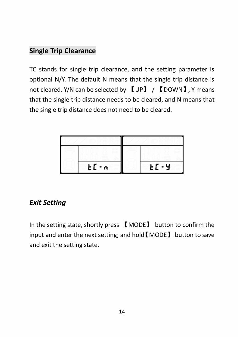
Single Trip Clearance
TC stands for single trip clearance, and the setting parameter is optional N/Y. The default N means that the single trip distance is not cleared. Y/N can be selected by 【UP】 / 【DOWN】, Y means that the single trip distance needs to be cleared, and N means that the single trip distance does not need to be cleared.
Exit Setting
In the setting state, shortly press 【MODE】 button to confirm the input and enter the next setting; and hold【MODE】 button to save and exit the setting state.

15
Password Setting
Hold 【UP】 and 【DOWN】 buttons simultaneously for 2 seconds to enter the normal setting state; then hold【UP】 and 【MODE】 buttons simultaneously for 2 seconds to enter the power-on password setting state. The display prompts “PSD.2”, indicating that you need to enter the power-on password. Press the 【MODE】 button to shift, and increase/decrease the input value by 【UP】 /【DOWN】. After the 4-digit password is entered, press the 【MODE】 key to confirm. If the password is correct, enter the power-on password user setting interface, otherwise it will stay in the password input state. Hold【MODE】button to exit. The factory default is: 1234.
Password Use
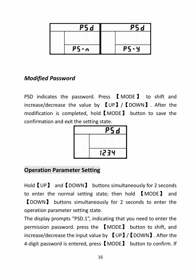
By 【UP】/【DOWN】 to select Y/N. Y means that the power-on password is required, and N means that the power-on password is not required. Press 【MODE】 to confirm and enter the password modification interface.
16
Modified Password
PSD indicates the password. Press 【MODE】 to shift and increase/decrease the value by 【UP】/【DOWN】. After the modification is completed, hold【MODE】 button to save the confirmation and exit the setting state.
Operation Parameter Setting
Hold【UP】 and【DOWN】 buttons simultaneously for 2 seconds to enter the normal setting state; then hold 【MODE】 and 【DOWN】 buttons simultaneously for 2 seconds to enter the operation parameter setting state. The display prompts “PSD.1”, indicating that you need to enter the permission password. press the 【MODE】 button to shift, and increase/decrease the input value by 【UP】/【DOWN】. After the 4-digit password is entered, press【MODE】 button to confirm. If

17
the password is correct, enter the power-on password setting interface, otherwise it will stay in the password input state. Hold【MODE】to exit. The permission password is: 0512.
Wheel Size Setting
LD stands for wheel diameter setting. Available values are: 16inch, 18 inch, 20 inch, 22 inch, 24 inch, 26 inch, 700C, 28 inch, 29 inch. By【UP】/【DOWN】 to select the wheel diameter corresponding to the e-bike to ensure the accuracy of the speed display and mileage display. Press 【MODE】to confirm and enter the speed limit setting interface. The factory default wheel diameter value is 26inch.
Speed Limit Setting
LS indicate the speed limit setting. The default maximum riding

18
speed is 25Km/h. Change this value to set the maximum riding speed of the e-bike. When the electric motor exceeds the set value, the controller will stop supplying power to the motor to protect the rider's safety. The maximum speed setting can be selected from 12Km/h to 40Km/h. It can be set by 【UP】/【DOWN】. After the modification is completed, press and hold the【MODE】button to save the confirmation and exit the setting.
Personalization
In order to enhance the personalized use of this product, we have specifically added this setting. It can be set for different requirements of users. In this setting, the display's battery indicator setting, PAS level setting, current limit setting, PAS sensor setting, speed sensor setting, throttle function setting and system setting are included. A total of seven items, detailed settings are shown in table 3.
Personalization Password Input
Hold【UP】 and 【DOWN】buttons simultaneously for 2 seconds

19
to enter the normal setting state; then hold【UP】 and【DOWN】 buttons simultaneously again for 2 seconds to enter the personalized parameter setting state. The display prompts “PSD.3”, indicating that you need to enter the permission password. Press 【 MODE 】 button to shift, and increase/decrease the input value by 【UP】/【DOWN】. After the 4-digit password is entered, press 【MODE】 button to confirm. If the password is correct, enter the power-on password setting interface, otherwise it will stay in the password input state. Hold【MODE】to exit. The permission password is: 2962.

20
By 【UP】/【DOWN】 to select the content to be set, and press 【MODE】 to enter the corresponding setting interface.
Battery Indicator Setting
VOL indicates the battery indicator setting. It is required to input the voltage values of 1 to 5 one by one. Take the first battery value as an example: “1” on the display indicates the first voltage and “31.5” is the first battery value. Change the value by increasing/decreasing with 【UP】/【DOWN】. Press 【MODE】 to confirm and enter the next battery value setting. After the 5 power values are set, press 【MODE】 to confirm and return to the personalization parameter setting interface.
21
PAS Parameter Setting
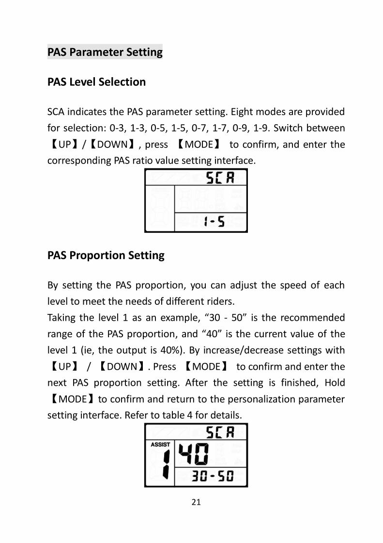
PAS Level Selection
SCA indicates the PAS parameter setting. Eight modes are provided for selection: 0-3, 1-3, 0-5, 1-5, 0-7, 1-7, 0-9, 1-9. Switch between【UP】/【DOWN】, press 【MODE】 to confirm, and enter the corresponding PAS ratio value setting interface.
PAS Proportion Setting
By setting the PAS proportion, you can adjust the speed of each level to meet the needs of different riders. Taking the level 1 as an example, “30 - 50” is the recommended range of the PAS proportion, and “40” is the current value of the level 1 (ie, the output is 40%). By increase/decrease settings with 【UP】 / 【DOWN】. Press 【MODE】 to confirm and enter the next PAS proportion setting. After the setting is finished, Hold【MODE】to confirm and return to the personalization parameter setting interface. Refer to table 4 for details.
22
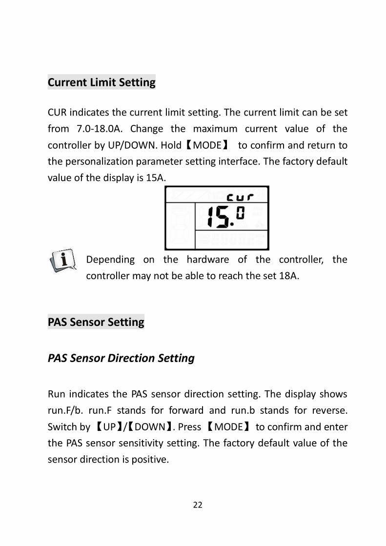
Current Limit Setting
CUR indicates the current limit setting. The current limit can be set from 7.0-18.0A. Change the maximum current value of the controller by UP/DOWN. Hold【MODE】 to confirm and return to the personalization parameter setting interface. The factory default value of the display is 15A.
Depending on the hardware of the controller, the controller may not be able to reach the set 18A.
PAS Sensor Setting
PAS Sensor Direction Setting
Run indicates the PAS sensor direction setting. The display shows run.F/b. run.F stands for forward and run.b stands for reverse. Switch by 【UP】/【DOWN】. Press 【MODE】 to confirm and enter the PAS sensor sensitivity setting. The factory default value of the sensor direction is positive.

23
PAS Sensor Sensitivity Setting
The display shows SCN, indicating the sensitivity of the PAS sensor. The setting range is 2-9. 2 indicate the highest sensitivity and 9 indicate the lowest sensitivity. Increase/decrease setting values by 【UP】/【DOWN】. Press 【MODE】to confirm and enter the PAS sensor proportion parameter setting interface. The factory default value is 2.
PAS Sensor Proportion Parameter Setting
N-represents the PAS sensor proportional parameter. The power sensor parameter values can be selected by 【UP】/【DOWN】. The larger the value, the more obvious the PAS feeling. Hold【MODE】 to confirm and return to the personalization parameter setting interface.

24
Speed Sensor Setting
SPS indicates the speed sensor setting. It can be set according to the number of magnet heads mounted on the wheel of the e-bike, and the setting range is 1-9. Modify it by pressing 【UP】/【DOWN】. Hold【MODE】 to confirm and return to the personalization parameter setting interface. The factory default value is 1.
Throttle Function Setting
Throttle Push Cruise Control Enable Setting
HL indicates the throttle’s push cruise control. HL: N means that the throttle does not has this function, and HL: Y means that throttle has this function, that is, when turning the throttle, the display enters the push cruise control mode. Y/N can be switched by 【UP】/【DOWN】. If you select N, press 【MODE】 shortly to confirm and enter the throttle PAS level setting interface, otherwise there is no response. Hold【MODE】 to confirm and
25
return to the display’s personalization parameter setting interface. The factory default value of the display is N.
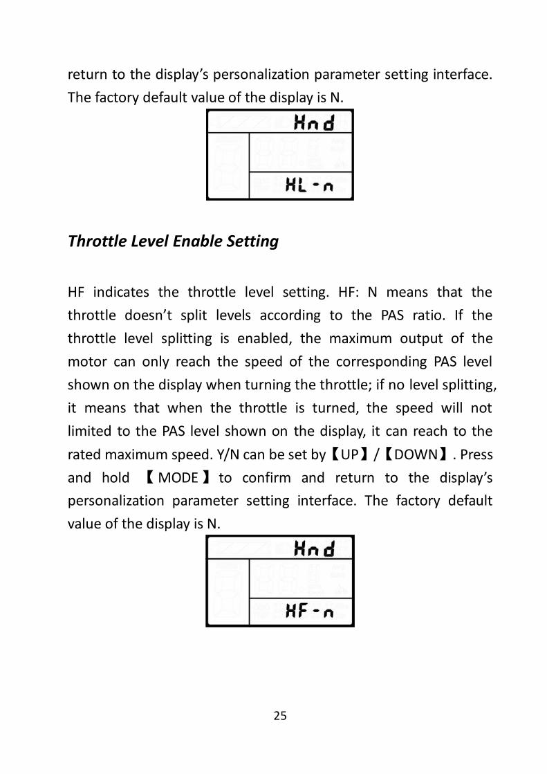
Throttle Level Enable Setting
HF indicates the throttle level setting. HF: N means that the throttle doesn’t split levels according to the PAS ratio. If the throttle level splitting is enabled, the maximum output of the motor can only reach the speed of the corresponding PAS level shown on the display when turning the throttle; if no level splitting, it means that when the throttle is turned, the speed will not limited to the PAS level shown on the display, it can reach to the rated maximum speed. Y/N can be set by【UP】/【DOWN】. Press and hold 【MODE】 to confirm and return to the display’s personalization parameter setting interface. The factory default value of the display is N.
26
System Setting
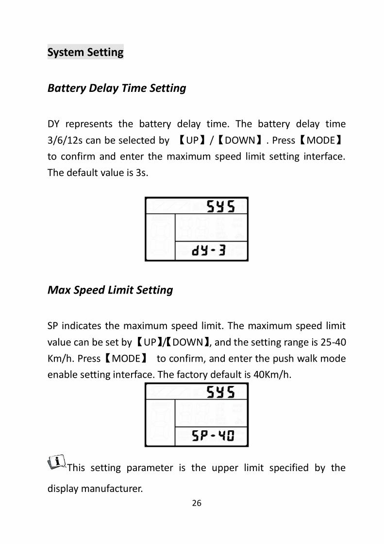
Battery Delay Time Setting
DY represents the battery delay time. The battery delay time 3/6/12s can be selected by 【UP】/【DOWN】. Press【MODE】to confirm and enter the maximum speed limit setting interface. The default value is 3s.
Max Speed Limit Setting
SP indicates the maximum speed limit. The maximum speed limit value can be set by 【UP】/【DOWN】, and the setting range is 25-40 Km/h. Press【MODE】 to confirm, and enter the push walk mode enable setting interface. The factory default is 40Km/h.
This setting parameter is the upper limit specified by the
display manufacturer.

27
Push Cruise Control Enable Setting
PUS indicates the push cruise control enable setting. Y/N can be switched by【UP】/【DOWN】. Y means enable, that is, hold 【DOWN】, the push cruise control function can be realized; N means no enable, that is, no push cruise control function. Press【MODE】 to confirm and enter the push cruise control speed setting. The factory default value of the display is Y.
Push Speed Setting
PU indicates the push speed setting. By setting the assist speed value, you can adjust the pushing speed to meet the needs of different riders. Adjusted by【UP】/【DOWN】, the adjustable range is “20-35”. Press 【MODE】 to confirm and enter the slow start setting interface. The display defaults to 25 (ie, 25% output).

28
Slowly Start up Setting
SSP indicates the slowly start up setting. The adjustable range is 1-4. 4 is the slowest. Select with 【UP】/【DOWN】. Press and hold【MODE】 to confirm and return to the display’s personalization parameter setting interface. The display defaults to factory default 1.
Exit Setting
In the personalized parameter setting state: press 【MODE】 to confirm the input to enter the next setting; hold 【MODE】 to confirm the current setting and exit the current setting state; hold【DOWN】 to cancel the current operation, exit without saving the current set data.
The display exits the setting state automatically without any
operation for one minute.

29
Restore Default Setting
DEF means to restore the default parameters. Hold【DOWN】and【MODE】buttons simultaneously for 2 seconds to enter the Restore Default Parameters interface. Switch Y or N with 【UP】/【DOWN】. Y indicates that the default parameters need to be restored. Hold【MODE】 to confirm. If you select Y, you need to enter the permission password to restore the default parameters.
The permission password is 0368. Press 【MODE】 to shift and increase/decrease the value by 【UP】/【DOWN】. After the 4-digit password is entered, press 【MODE】to confirm. The display will automatically exit after successful recovery.
In the recovery default, the battery indicator, ODO and TRIP
are unrecoverable, but the power-on password is in recovery.

30
FAQ Answers
Q: Why can’t turn on the display? A: Check if the battery power is turned on, the outer leakage cable is broken or not. Q: What should I do if the display shows error code? A: Timely repair at the e-bike repair shop.
Quality Warranty And Coverage
I. Warranty: 1. In the case of normal use, due to the quality problems caused by the product itself, the company will be responsible for the warranty during the warranty period. 2. The warranty: 24 months since the display out of the factory.
II. The following conditions are not covered by the warranty: 1. The casing is opened 2. Connector is broken

31
3. The display leaves the factory, the casing is scratched or the casing is damaged. 4. Scratch or break of the display lead wire 5. Failure or damage caused by force majeure (such as fire, earthquake, etc.) or natural disasters (such as lightning strikes) 6. Product is out of warranty.
Circuit Block Diagram
Standard Connector Wire Sequence
Connect to the controller Display Outlet Connection Interface Table:Standard connector wire sequence table
Standard Wiring
Standard Wiring Color
Function
1 Red(VCC) Display power Wire 2 Blue(K) Controller Power Control
Wire 3 Black(GND) Display Ground Wire 4 Green(RX) Display Data Receiving
Wire
32
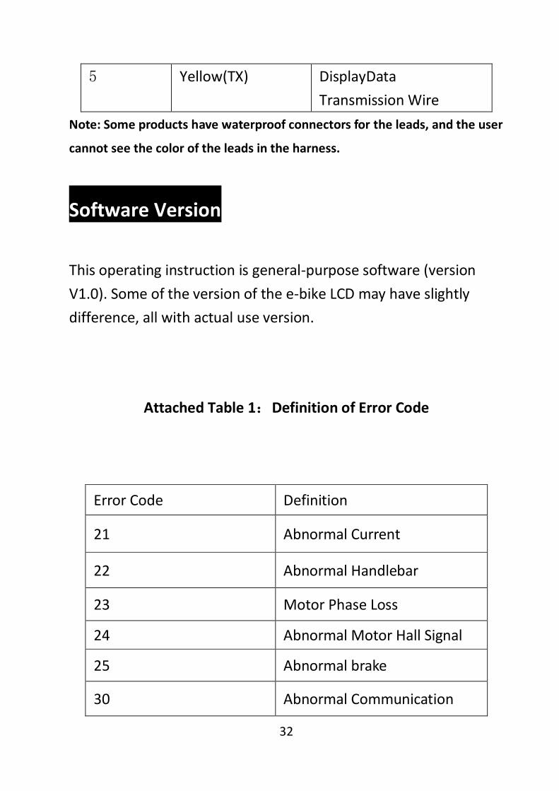
5 Yellow(TX) DisplayData Transmission Wire
Note: Some products have waterproof connectors for the leads, and the user
cannot see the color of the leads in the harness.
Software Version
This operating instruction is general-purpose software (version V1.0). Some of the version of the e-bike LCD may have slightly difference, all with actual use version.
Attached Table 1:Definition of Error Code
Error Code Definition
21 Abnormal Current
22 Abnormal Handlebar
23 Motor Phase Loss
24 Abnormal Motor Hall Signal
25 Abnormal brake
30 Abnormal Communication

33

34
Attached Table 2:Password Checklist
S/N Screen Display Password Description
1
0512
Operation parameter
setting password (Fixed)
2
Default Password
1234
Power-on password (Can be modified)
3
2962
Password for personality parameter
setting (Fixed)
4
0368 Restore setup
password (Fixed)

35
Attached Table 3:Personalization Parameters Table
S/N Setting
Item Screen Display
Setting Content
1 Battery
Indicator Setting
5 Battery Value Setting
2 PAS Level
Setting
PAS Level Selection
PAS Ratio
3 Current
Limit setting
Limit Current Value
4 PAS Sensor
Setting
PAS Sensor Direction
PAS Sensor Sensitivity
5 Speed Sensor Setting
Speed Sensor Magnet
Steel Number
36
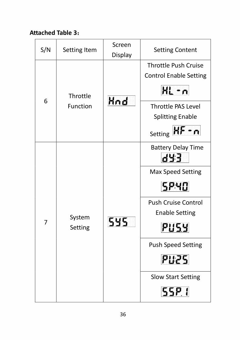
Attached Table 3:
S/N Setting Item Screen Display
Setting Content
6 Throttle Function
Throttle Push Cruise Control Enable Setting
Throttle PAS Level Splitting Enable
Setting
7 System Setting
Battery Delay Time
Max Speed Setting
Push Cruise Control Enable Setting
Push Speed Setting
Slow Start Setting

37
Attached Table 4:PASProportion Default Value
PAS
Level
Option
1 2 3 4 5 6 7 8 9
0-3/ 1-3 47% 72% 92% — — — — — —
0-5/ 1-5 40% 55% 70% 85% 95% — — — —
0-7/ 1-7 35% 46% 57% 68% 79% 90% 97% — —
0-9/ 1-9 25% 34% 43% 52% 61% 70% 79% 88% 96%

38
KING-METER