j transmission design
TRANSCRIPT
8/13/2019 J Transmission Design
http://slidepdf.com/reader/full/j-transmission-design 1/27
T R A N S M I S S I O N
D E S I G NGeneral Engineering ....................... J-1
Structural Analysis ........................... J-4
Pole Dimensions .............................J-11
Stresses in Down Guys..................J-14
Double Arm Assemblies ..............J-15
Davit Arm vs Post Insulator ......... J-16
Testing ................................................ J-18
Tower Configurations.................... J-22
HUGHESBROTHERS, INC.
SEWARD, NE

8/13/2019 J Transmission Design
http://slidepdf.com/reader/full/j-transmission-design 2/27
Transmission Design
J-1
www.hughesbros.com Hughes Brothers, Inc.P.O. Box 159 / 210 N 13th / Seward, NE 68434 / Phone (402) 643-2991 / Fax (402) 643-2149©2012 Hughes Brothers, Inc.
Since the early 1920’s, the Hughes Brothers' engineering staff
has assisted in the construction of more than a hundred thousandcircuit miles of overhead construction.
Our engineering staff is prepared to
offer their assistance by providing:
• Structural analysis of tower congurations
• Full scale testing
• Design & computer aided drafting
• Cost analysis and competitive bid analysis • Project administration i.e., order processing,
expediting, delivery coordination for the materials
we supply.
• Field inspection and customer service
This catalog section gives full consideration to the
following important design criteria:
1) The most economically designed tangent structure,
which considers only a maximum span, does not
usually or necessarily result in the most economicaltransmission line.
2) Properly designed, efcient transmission structures
result from a complete study of the route of the line,including prole, soil types, number and magnitude of
angles, and the unusual and local conditions whichare a part of any line.
3) Braced H-Frame lines have been built at a savings
over unbraced H-Frame lines, resulting in greater
strength and lower maintenance.
4) H-Frame lines can and have been built at a
savings in cost over single pole lines.
5) Full size tests should be made on new develop-
ments before they are used in actual construction.
6) Successful transmission line construction is notbased on the length of time in service, but whether
it has been subjected to the load for which it was
designed.
In the presentation of this manual, we have tried toindicate to designers, operators and builders of over-
head construction that our staff of engineers and our
testing laboratory are available to the utility industry.
Transmission engineers are fully aware that the mere assembly of poles, arms, braces, insulators,conductors, guys and hardware is not transmission construction. Properly designed transmission
structures result from a complete study of all the conditions affecting the project.
General Engineering

8/13/2019 J Transmission Design
http://slidepdf.com/reader/full/j-transmission-design 3/27
J Transmission Design
Hughes Brothers, Inc. www.hughesbros.com
P.O. Box 159 / 210 N 13th / Seward, NE 68434 / Phone (402) 643-2991 / Fax (402) 643-2149©2012 Hughes Brothers, Inc.
J-2
The selection of the design of the tangent structure
should be made with reference to the overall cost of
the line which will include an analysis of the prole,
conductor, right of way and local conditions affectingspan lengths.
In general, Type C construction shown below, will
rarely produce the most economical line. The spanlength will be limited, requiring more structures and
associated parts; the deection and earth pressure
will be excessive.
The simple installation of the X-brace, as in Type B will
eliminate deection, reduce earth pressure, permit the
use of smaller poles and result in longer spans and
greater safety factors.
The Type A design will usually result in the safest,
strongest and most economical long span, high voltage
structure. The knee or vee braces permit the pole topsto act as guided cantilevers by introducing a point of
inection between the cross arm and top of the
X-braces. Without these braces, the poles above the
X-Braces act as simple cantilevers.
Taken from Hughes Brothers 1937 catalog.

8/13/2019 J Transmission Design
http://slidepdf.com/reader/full/j-transmission-design 4/27
Transmission Design
www.hughesbros.com Hughes Brothers, Inc.P.O. Box 159 / 210 N 13th / Seward, NE 68434 / Phone (402) 643-2991 / Fax (402) 643-2149©2012 Hughes Brothers, Inc.
J-3
Full Scale Structure Tests -
A Continuing Process
1955
1986
1935

8/13/2019 J Transmission Design
http://slidepdf.com/reader/full/j-transmission-design 5/27
J-4
Hughes Brothers, Inc. www.hughesbros.com
P.O. Box 159 / 210 N 13th / Seward, NE 68434 / Phone (402) 643-2991 / Fax (402) 643-2149©2012 Hughes Brothers, Inc.
J Structural Analysis
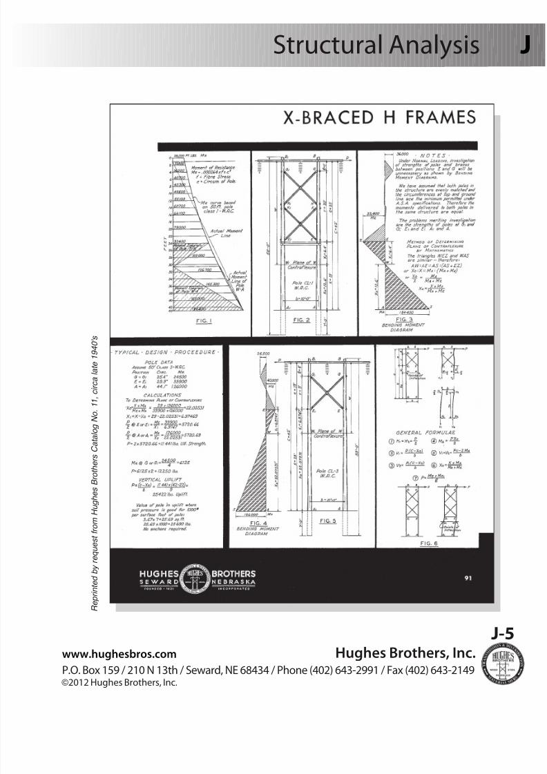
Principles that were used 50 years ago are still applicable today
R e p r i n t e d b y r e q u e s t f r o m
H u g h e s B r o t h e r s C a t a l o g N o .
1 1 ,
c i r c a l a t e 1 9 4 0 ' s
8/13/2019 J Transmission Design
http://slidepdf.com/reader/full/j-transmission-design 6/27
www.hughesbros.com Hughes Brothers, Inc.P.O. Box 159 / 210 N 13th / Seward, NE 68434 / Phone (402) 643-2991 / Fax (402) 643-2149©2012 Hughes Brothers, Inc.
J-5
Structural Analysis
R e p r i n t e d b y r e q u e s t f r o m
H u g h e s B r o t h e r s C a t a l o g N o . 1
1 , c i r c a l a t e 1 9 4 0 ' s

8/13/2019 J Transmission Design
http://slidepdf.com/reader/full/j-transmission-design 7/27
Hughes Brothers, Inc. www.hughesbros.com
P.O. Box 159 / 210 N 13th / Seward, NE 68434 / Phone (402) 643-2991 / Fax (402) 643-2149©2012 Hughes Brothers, Inc.
J-6
J Structural Analysis
Ultimate Circumference Pole Moment
Location in Inches (ft-lbs.)
a 46.92 218,183 b 35.69 96,025
c 30.48 59,808
d 28.14 46,804
Theoretical Maximum Transverse Span Analysisof Hughes Brothers H-Frame Structures
List of Assumptions
1. Plane surfaces will remain plane and
bracing will create a plane ofcontraexure (point of zero moment).
2. Horizontal load is equally distributed
between the poles.
3. Pole taper is to be uniform for the
entire length of pole.
4. Foundations are rigid and xed.
NOTE: Circumferences are based on ANSI minimumdimensions.
Find location of planes of contraexure:
X0 =X Ma
=31.25 ft. ¥218,183 ft - lbs.
= 21.70 ft.
X1 = X - X0 = 31.25 ft. - 21.70 ft.= 9.55ft.
Y0 =YMc
=6.5 ft. ¥59,808 ft - lbs.
= 3.64 ft.
X0 = Y - Y0 = 6.5 ft. - 3.64 ft. = 2.86
1. Bending stress of pole = 8,000 psi
2. Y = 6'-6"3. Crossarm height = 8'-9"
4. Z = Pole spacing minus 1 ft
5. 70', class 2 Douglas-r poles
6. Set depth = 9'-0"7. Pole spacing = 15'-6"
Initial Conditions:
a
G.L.PS
Y1
Y0
Z
X1
X0
X
Y Plane ofContraexure
d
c
b
Plane of
Contraexure
CrossarmHeight
Find ultimate pole moments at locations a, b, c, d:
M = s f =π d3
(f) =π c3
(f) therefore:
M = 0.000264fc3 (ft - lbs.), where
f = Bending stress of pole
c = Circumference(inches) at each location
s = Section modulus at each location(in3)
M = Moment (ft - lbs.)
(12)32 32π 3
(12)
Ma + Mb 218,183 ft - lbs. + 96,025 ft - lbs.
Mc + Md 59,808 ft - lbs. + 47,084 ft - lbs.

8/13/2019 J Transmission Design
http://slidepdf.com/reader/full/j-transmission-design 8/27
www.hughesbros.com Hughes Brothers, Inc.P.O. Box 159 / 210 N 13th / Seward, NE 68434 / Phone (402) 643-2991 / Fax (402) 643-2149©2012 Hughes Brothers, Inc.
J-7
Structural Analysis
H-Frame Structure
Strength Analysis(cont'd)
List of Assumptions
1. Plane surfaces will remain plane andbracing will create a plane ofcontraexure (point of zero moment).
2. Horizontal load is equally distributedbetween the poles.
3. Pole taper is uniform for the entirelength of pole.
4. Foundations are rigid and xed.
Find maximum load (P) to fail poles at each location:
where: L =Unbraced length in inches, assumed to be 1/2 of the brace length
I = Moment of inertia
E = Modulus of Elasticity
b
CrossarmHeight
Y1
Y0
Y
Z
X1
X0
XPlane of
Contraexure
Plane ofContraexure
d
c
aPS
Pa =2Ma
=2 x 218,183 ft - lbs.
= 20,109 lbs.
Pb =2Mb
=2 x 96,025 ft - lbs.
= 20,109 lbs.
Pc =2Mc
=2 x 59,808 ft - lbs.
= 32,890 lbs.
Pd =2Md
=2 x 47,084 ft - lbs.
= 32,890 lbs.
Maximum P allowed:
Assume 15% strength reduction due to bolt holes etc.
20,109 lbs. - (.85) = 17,093 lbs.
II. Check Strength of 1042 style X - Brace
A. Compression Theoretical X - Brace Strength [Px] from Euler's Formula
Px =π 2 El
X0 21.70 ft.
X1 9.55 ft.
Y0 3.64 ft.
Y1 2.86 ft.
L2
Px =π 2 x 1.6 x 106 psi x 17.22 in.4
= 17,963 lbs.
B. Tension The Hughes Brothers 1042X - Brace is limited to
20,000 pounds which is determined empirically
( 14.5 (0.5)ft. x 12 in./ft.)2cos 45
G.L.
8/13/2019 J Transmission Design
http://slidepdf.com/reader/full/j-transmission-design 9/27
Hughes Brothers, Inc. www.hughesbros.com
P.O. Box 159 / 210 N 13th / Seward, NE 68434 / Phone (402) 643-2991 / Fax (402) 643-2149©2012 Hughes Brothers, Inc.
J-8
J Structural Analysis
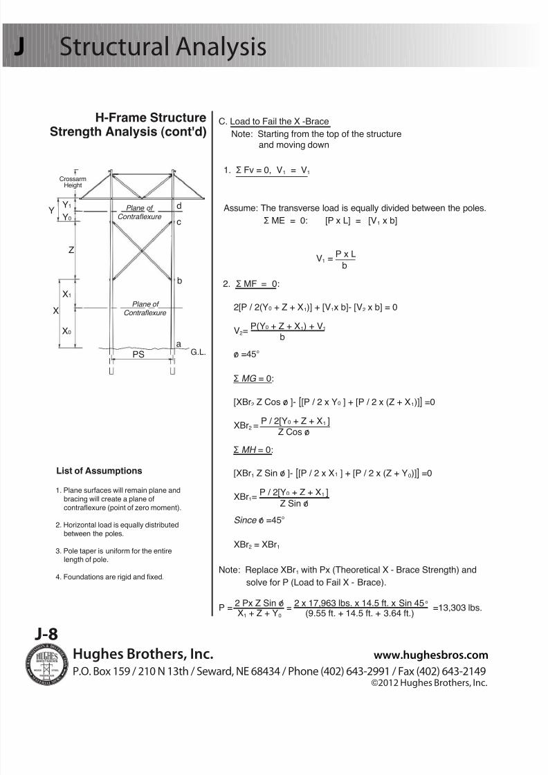
C. Load to Fail the X -Brace
Note: Starting from the top of the structure and moving down
1. Ʃ Fv = 0, V1 = V1
Assume: The transverse load is equally divided between the poles.
Ʃ ME = 0: [P x L] = [V1 x b]
V1 =P x L
2. Ʃ MF = 0:
2[P / 2(Y0 + Z + X1)] + [V1x b]- [V2 x b] = 0
V2=P(Y0 + Z + X1) + V1
o =45o
Ʃ MG = 0:
[XBr2 Z Cos o ]- [[P / 2 x Y0 ] + [P / 2 x (Z + X1)]] =0
XBr2 =P / 2[Y0 + Z + X1 ]
Ʃ MH = 0:
[XBr1 Z Sin o ]- [[P / 2 x X1 ] + [P / 2 x (Z + Y0)]] =0
XBr1=P / 2[Y0 + Z + X1 ]
Since o =45o
XBr2 = XBr1
Note: Replace XBr1 with Px (Theoretical X - Brace Strength) and
solve for P (Load to Fail X - Brace).
P =2 Px Z Sin o
=2 x 17,963 lbs. x 14.5 ft. x Sin 45o
=13,303 lbs.
b
b
/
Z Cos o
/
/
Z Sin o/
/
/
H-Frame Structure
Strength Analysis (cont'd)
List of Assumptions
1. Plane surfaces will remain plane andbracing will create a plane ofcontraexure (point of zero moment).
2. Horizontal load is equally distributedbetween the poles.
3. Pole taper is uniform for the entirelength of pole.
4. Foundations are rigid and xed.
b
CrossarmHeight
Y1
Y0
Y
Z
X1
X0
XPlane of
Contraexure
Plane ofContraexure
d
c
aPS G.L.
/
X1 + Z + Y0 (9.55 ft. + 14.5 ft. + 3.64 ft.)
8/13/2019 J Transmission Design
http://slidepdf.com/reader/full/j-transmission-design 10/27
J-9
www.hughesbros.com Hughes Brothers, Inc.P.O. Box 159 / 210 N 13th / Seward, NE 68434 / Phone (402) 643-2991 / Fax (402) 643-2149©2012 Hughes Brothers, Inc.
Structural Analysis
H-Frame Structure
Strength Analysis(cont'd)
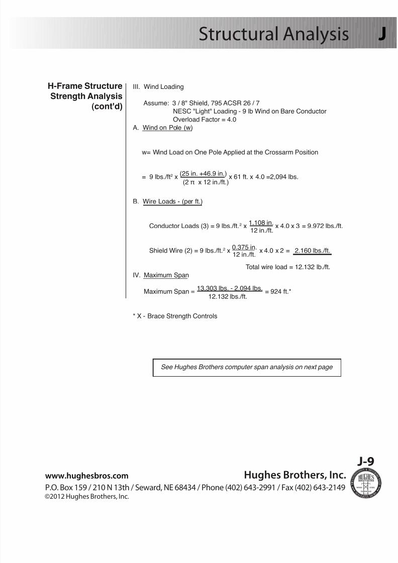
See Hughes Brothers computer span analysis on next page
III. Wind Loading
Assume: 3 / 8" Shield, 795 ACSR 26 / 7
NESC "Light" Loading - 9 lb Wind on Bare Conductor
Overload Factor = 4.0
A. Wind on Pole (w)
w= Wind Load on One Pole Applied at the Crossarm Position
= 9 lbs./ft2 x(25 in. +46.9 in.)
x 61 ft. x 4.0 =2,094 lbs.
B. Wire Loads - (per ft.)
Conductor Loads (3) = 9 lbs./ft.2 x1.108 in.
x 4.0 x 3 = 9.972 lbs./ft.
Shield Wire (2) = 9 lbs./ft.2 x0.375 in.
x 4.0 x 2 = 2.160 lbs./ft.
Total wire load = 12.132 lb./ft.
IV. Maximum Span
Maximum Span =13,303 lbs. - 2,094 lbs.
= 924 ft.*
* X - Brace Strength Controls
(2 π x 12 in./ft.)
12 in./ft.
12 in./ft.
12.132 lbs./ft.
8/13/2019 J Transmission Design
http://slidepdf.com/reader/full/j-transmission-design 11/27
Hughes Brothers, Inc. www.hughesbros.com
P.O. Box 159 / 210 N 13th / Seward, NE 68434 / Phone (402) 643-2991 / Fax (402) 643-2149©2012 Hughes Brothers, Inc.
J-10
J Structural Analysis
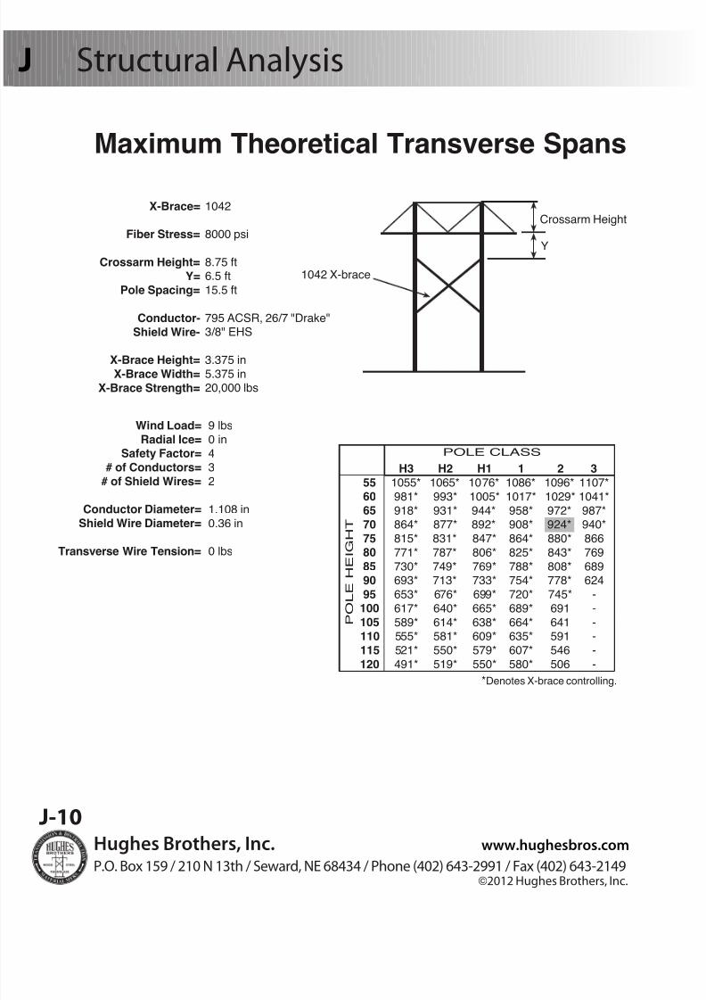
X-Brace=
Fiber Stress=
Crossarm Height=
Y=Pole Spacing=
Conductor-
Shield Wire-
X-Brace Height=
X-Brace Width=
X-Brace Strength=
1042
8000 psi
8.75 ft6.5 ft
15.5 ft
795 ACSR, 26/7 "Drake"3/8" EHS
3.375 in
5.375 in20,000 lbs
Wind Load=
Radial Ice=Safety Factor=
# of Conductors=
# of Shield Wires=
Conductor Diameter=
Shield Wire Diameter=
Transverse Wire Tension=
9 lbs
0 in
43
2
1.108 in
0.36 in
0 lbs
Crossarm Height
Y
1042 X-brace
H3 H2 H1 1 2 3 55 1055* 1065* 1076* 1086* 1096* 1107*
60 981* 993* 1005* 1017* 1029* 1041*
65 918* 931* 944* 958* 972* 987*
70 864* 877* 892* 908* 924* 940* 75 815* 831* 847* 864* 880* 866
80 771* 787* 806* 825* 843* 769
85 730* 749* 769* 788* 808* 689 90 693* 713* 733* 754* 778* 624
95 653* 676* 699* 720* 745* -
100 617* 640* 665* 689* 691 -
105 589* 614* 638* 664* 641 - 110 555* 581* 609* 635* 591 -
115 521* 550* 579* 607* 546 -
120 491* 519* 550* 580* 506 -
POLE CLASS
P O L E
H E I G H T
*Denotes X-brace controlling.
Maximum Theoretical Transverse Spans

8/13/2019 J Transmission Design
http://slidepdf.com/reader/full/j-transmission-design 12/27
www.hughesbros.com Hughes Brothers, Inc.P.O. Box 159 / 210 N 13th / Seward, NE 68434 / Phone (402) 643-2991 / Fax (402) 643-2149©2012 Hughes Brothers, Inc.
J-11
Pole Dimensions
To determine the diameter of a pole at any given distance from the top:
1. Find the butt circumference by selecting the pole class in row 1
2. Move down the column to the desired pole length 3. Select the pole top circumference from row 2
4. Perform the following calculation:
NOTE: Pole circumference tables
located on pages J-12 & J-13
Determining Pole Diameters
Special Note: The diameter found is a minimum pole dimension, based on ANSI 05.1.
Most poles will run larger than this dimension.
Circumference at any point =
Circumference- Top Circumference
x Distrance from Top + Top Circumference
Diameter at any point =
Circumference
π = 3.14
at 6 ft. from Butt
(Pole Length - 6)( (
π

8/13/2019 J Transmission Design
http://slidepdf.com/reader/full/j-transmission-design 13/27
Hughes Brothers, Inc. www.hughesbros.com
P.O. Box 159 / 210 N 13th / Seward, NE 68434 / Phone (402) 643-2991 / Fax (402) 643-2149©2012 Hughes Brothers, Inc.
J-12
J Pole Dimensions
C l a s s
M i n i m u m c
i r c u m f e r e
n c e
a t t o p
( i n . )
L e n g t h
o f
p o l e
( f t . )
G r o u n d l i n e * *
d i s t a n
c e
f r o m b
u t t
( f t . )
H - 6
H - 5
H - 4
H - 3
H - 2
H - 1
1
2
3
4
5
6
7
9
1 0
3 9
3 7
3 5
3 3
3 1
2 9
2 7
2 5
2 3
2 1
1 9
1 7
1 5
1 5
1 2
M i n i m u m
c i r c u m f e r e n c e a t 6 f t f r o m b
u t t ( i n . )
2 0
4 . 0
2 5
5 . 0
3 0
5 . 5
3 5
6 . 0
4 0
6 . 0
4 5
6 . 5
5 0
7 . 0
5 5
7 . 5
6 0
8 . 0
6 5
8 . 5
7 0
9 . 0
7 5
9 . 5
8 0
1 0
8 5
1 0 . 5
9 0
1 1 . 0
9 5
1 1 . 0
1 0 0
1 1 . 0
1 0 5
1 2 . 0
1 1 0
1 2 . 0
1 1 5
1 2 . 0
1 2 0
1 2 . 0
1 2 5
1 2 . 0
-
-
-
-
-
-
3 1
. 0
2 9
. 0
2 7 . 0
2 5
. 0
2 3
. 0
2 1
. 0
1 9
. 5
1
7 . 5
1 4
. 0
-
-
-
-
-
-
3 3
. 5
3 1
. 5
2 9 . 5
2 7
. 5
2 5
. 5
2 3
. 0
2 1
. 5
1
9 . 5
1 5
. 0
-
-
-
-
-
-
3 6
. 5
3 4 . 0
3 2 . 0
2 9 . 5
2 7 . 5
2 5 . 0
2 3 . 5
2 0 . 5
-
-
-
-
-
4 3 . 5
4 1 . 5
3 9
. 0
3 6 . 5
3 4 . 0
3 1 . 5
2 9 . 0
2 7 . 0
2 5 . 0
-
-
-
-
5 1 . 0
4 8 . 5
4 6 . 0
4 3 . 5
4 1 . 0
3 8 . 5
3 6 . 0
3 3 . 5
3 1 . 0
2 8 . 5
-
-
-
5 8 . 5
5 6 . 0
5 3 . 5
5 1 . 0
4 8 . 5
4 5 . 5
4 3 . 0
4 0 . 5
3 7 . 5
3 5 . 0
3 2 . 5
3 0
. 0
-
-
-
6 1 . 0
5 8 . 5
5 5 . 5
5 3 . 0
5 0 . 5
4 7 . 5
4 5 . 0
4 2 . 0
3 9 . 0
3 6
. 5
3 4
. 0
-
-
-
-
6 3 . 5
6 0 . 5
5 8 . 0
5 5 . 0
5 2 . 0
4 9 . 5
4 6 . 5
4 3 . 5
4 0 . 5
3 8
. 0
-
-
-
-
-
6 5 . 5
6 2 . 5
5 9 . 5
5 7 . 0
5 4 . 0
5 1 . 0
4 8 . 0
4 5 . 0
4 2 . 0
3 9
. 0
-
-
-
-
-
6 7 . 5
6 4 . 5
6 1 . 5
5 8 . 5
5 5 . 5
5 2 . 5
4 9 . 5
4 6 . 5
4 3 . 5
4 0
. 5
-
-
-
-
-
6 9 . 0
6 6 . 5
6 3 . 5
6 0 . 5
5 7 . 0
5 4 . 0
5 1 . 0
4 8 . 0
4 5 . 0
4 1
. 5
-
-
-
-
-
7 1 . 0
6 8 . 0
6 5 . 0
6 2 . 0
5 9 . 0
5 5 . 5
5 2 . 5
4 9 . 0
4 6 . 0
-
-
-
-
-
-
7 2 . 5
6 9 . 5
6 6 . 5
6 3 . 5
6 0 . 0
5 7 . 0
5 4 . 0
5 0 . 5
4 7 . 0
-
-
-
-
-
-
7 4 . 5
7 1 . 5
6 8 . 0
6 5 . 0
6 1 . 5
5 8 . 5
5 5 . 0
5 1 . 5
4 8 . 0
-
-
-
-
-
-
7 6 . 0
7 3 . 0
6 9 . 5
6 6 . 5
6 3 . 0
5 9 . 5
5 6 . 0
5 3 . 0
4 9 . 0
-
-
-
-
-
-
7 7 . 5
7 4 . 5
7 1 . 0
6 7 . 5
6 4 . 5
6 1 . 0
5 7 . 0
5 4 . 0
-
-
-
-
-
-
-
7 9 . 0
7 6 . 0
7 2 . 5
6 9 . 0
6 5 . 5
6 2 . 0
5 8 . 5
5 5 . 0
-
-
-
-
-
-
-
8 0 . 5
7 7 . 0
7 4 . 0
7 0 . 5
6 7 . 0
6 3 . 0
5 9 . 5
5 6 . 0
-
-
-
-
-
-
-
8 2 . 0
7 8 . 5
7 5 . 0
7 1 . 5
6 8 . 0
6 4 . 5
6 0 . 5
5 7 . 0
-
-
-
-
-
-
-
8 3 . 5
8 0 . 0
7 6 . 5
7 2 . 5
6 9 . 0
6 5 . 5
6 1 . 5
5 8 . 0
-
-
-
-
-
-
-
8 5 . 0
8 1 . 0
7 7 . 5
7 4 . 0
7 0 . 0
6 6 . 5
6 2 . 5
5 9 . 0
-
-
-
-
-
-
-
8 6 . 0
8 2 . 5
7 8 . 5
7 5 . 0
7 1 . 0
6 7 . 5
6 3 . 5
5 9 . 5
-
-
-
-
-
-
-
N O T E :
C l a s s e s a
n d l e n g
t h s
f o r w
h i c h c
i r c u m
f e r e n c e s a
t 6 f e e
t f r o m
t h e
b u
t t a r e
l i s t e d i n b o
l d f a c e
t y p e
a r e
t h e p r e
f e r r e
d s
t a n
d a r d s
i z e s .
T h o s e s h o w n
i n l i g h t t y p e a r e
i n c
l u d e
d f o r e n g
i n e e r i n g p u r p o s e s o n
l y .
* *
T h e
g u r e
s i n t h i s c o
l u m n a r e
i n t e n
d e
d f o r u s e o n
l y w
h e n a
d e
n
i t i o n o
f g r o u n
d l i n e
i s n e c e s s a r y
i n o r d e r t o a p p
l y r e q u
i r e m e n
t s r e
l a t i n g
t o s c a r s ,
s t r a i g h t n e s s ,
e t c
.
D i m e n s i o n s o f D o u g l a s - r ( b o t h
t y p e s ) a n d S o u t h e r n P i n e P o l e s
f r o m A N S I 0 5 . 1 - 1 9 9 2

8/13/2019 J Transmission Design
http://slidepdf.com/reader/full/j-transmission-design 14/27
www.hughesbros.com Hughes Brothers, Inc.P.O. Box 159 / 210 N 13th / Seward, NE 68434 / Phone (402) 643-2991 / Fax (402) 643-2149©2012 Hughes Brothers, Inc.
J-13
Pole Dimensions
C l a s s
M i n i m u m c
i r c u m f e r e
n c e
a t t o p
( i n . )
L e n g t h
o f
p o l e
( f t . )
G r o u n d l i n e * *
d i s t a n c e
f r o m b
u t t
( f t . )
H - 6
H - 5
H - 4
H - 3
H - 2
H - 1
1
2
3
4
5
6
7
9
1 0
3 9
3 7
3 5
3 3
3 1
2 9
2 7
2 5
2 3
2 1
1 9
1 7
1 5
1 5
1 2
M i n i m u m
c i r c u m f e r e n c e a t 6 f t f r o m b
u t t ( i n . )
2 0
4 . 0
2 5
5 . 0
3 0
5 . 5
3 5
6 . 0
4 0
6 . 0
4 5
6 . 5
5 0
7 . 0
5 5
7 . 5
6 0
8 . 0
6 5
8 . 5
7 0
9 . 0
7 5
9 . 5
8 0
1 0
8 5
1 0
. 5
9 0
1 1
. 0
9 5
1 1
. 0
1 0 0
1 1
. 0
1 0 5
1 2
. 0
1 1 0
1 2
. 0
1 1 5
1 2
. 0
1 2 0
1 2
. 0
1 2 5
1 2
. 0
-
-
-
-
-
-
3 3
. 5
3 1
. 5
2 9 . 5
2 7
. 0
2 5
. 0
2 3 . 0
2 1 . 5
1
8 . 5
1 5
. 0
-
-
-
-
-
-
3 7
. 0
3 4
. 5
3 2 . 5
3 0
. 0
2 8
. 0
2 5 . 5
2 4 . 0
2
0 . 5
1 6
. 5
-
-
-
-
-
-
4 0
. 0
3 7 . 5
3 5 . 0
3 2 . 5
3 0 . 0
2 8 . 0
2 6 . 0
2
2 . 0
-
-
-
-
-
4 8 . 0
4 5 . 5
4 2
. 5
4 0 . 0
3 7 . 5
3 4 . 5
3 2 . 0
3 0 . 0
2 7 . 5
-
-
-
-
5 6 . 5
5 3 . 5
5 1 . 0
4 8 . 0
4 5 . 0
4 2 . 5
3 9 . 5
3 6 . 5
3 4 . 0
3 1 . 5
-
-
-
6 4 . 5
6 2 . 0
5 9 . 0
5 6 . 0
5 3 . 5
5 0 . 5
4 7 . 5
4 4 . 5
4 1 . 5
3 8 . 5
3 6 . 0
3 3
. 0
-
-
-
6 7 . 0
6 4 . 5
6 1 . 5
5 8 . 5
5 5 . 5
5 2 . 5
4 9 . 5
4 6 . 5
4 3 . 5
4 0
. 0
3 7
. 5
-
-
-
-
7 0 . 0
6 7 . 0
6 4 . 0
6 1 . 0
5 7 . 5
5 4 . 5
5 1 . 5
4 8 . 5
4 5 . 0
4 2
. 0
-
-
-
-
-
7 2 . 0
6 9 . 0
6 6 . 0
6 3 . 0
5 9 . 5
5 6 . 5
5 3 . 5
5 0 . 0
4 6 . 5
4 3
. 5
-
-
-
-
-
7 4 . 5
7 1 . 5
6 8 . 0
6 5 . 0
6 1 . 5
5 8 . 5
5 5 . 0
5 1 . 5
4 8 . 0
4 5
. 0
-
-
-
-
-
7 6 . 5
7 3 . 5
7 0 . 0
6 7 . 0
6 3 . 5
6 0 . 0
5 6 . 5
5 3 . 0
4 9 . 5
4 6
. 0
-
-
-
-
-
7 8 . 5
7 5 . 5
7 2 . 0
6 8 . 5
6 5 . 0
6 1 . 5
5 8 . 0
5 4 . 5
5 1 . 0
-
-
-
-
-
-
8 0 . 5
7 7 . 0
7 4 . 0
7 0 . 5
6 7 . 0
6 3 . 0
5 9 . 5
5 6 . 0
5 2 . 0
-
-
-
-
-
-
8 2 . 5
7 9 . 0
7 5 . 5
7 2 . 0
6 8 . 5
6 4 . 5
6 1 . 0
5 7 . 0
5 3 . 5
-
-
-
-
-
-
8 4 . 5
8 1 . 0
7 7 . 0
7 3 . 5
7 0 . 0
6 6 . 0
6 2 . 5
5 8 . 5
5 4 . 5
-
-
-
-
-
-
8 6 . 0
8 2 . 5
7 9 . 0
7 5 . 0
7 1 . 5
6 7 . 5
6 3 . 5
5 9 . 5
-
-
-
-
-
-
-
8 7 . 5
8 4 . 0
8 0 . 5
7 6 . 5
7 2 . 5
6 9 . 0
6 5 . 0
6 1 . 0
-
-
-
-
-
-
-
8 9 . 5
8 5 . 5
8 2 . 0
7 8 . 0
7 4 . 0
7 0 . 0
6 6 . 0
6 2 . 0
-
-
-
-
-
-
-
9 1 . 0
8 7 . 0
8 3 . 5
7 9 . 5
7 5 . 5
7 1 . 5
6 7 . 5
6 3 . 0
-
-
-
-
-
-
-
9 2 . 5
8 8 . 5
8 4 . 5
8 0 . 5
7 6 . 5
7 2 . 5
6 8 . 5
6 4 . 0
-
-
-
-
-
-
-
8 4 . 0
9 0 . 0
8 6 . 0
8 2 . 0
7 8 . 0
7 4 . 0
6 9 . 5
6 5 . 0
-
-
-
-
-
-
-
9 5 . 5
9 1 . 5
8 7 . 5
8 3 . 0
7 9 . 0
7 5 . 0
7 0 . 5
6 6 . 0
-
-
-
-
-
-
-
N O T E :
C l a s s e s a
n d l e n g
t h s
f o r w
h i c h c
i r c u m
f e r e n c e s a
t 6 f e
e t f r o m
t h e
b u
t t a r e
l i s t e d i n b o
l d f a c e
t y p e
a r e
t h e p r e
f e r r e
d s
t a n
d a r d s
i z e s .
T h o s e s h o w n
i n l i g h t t y p e a r e
i n c
l u d e
d f o r e n g
i n e e r i n
g p u r p o s e s o n
l y .
*
D i m e n s i o n s o
f H
c l a s s e s a r e a p p
l i c a
b l e f o r w e s
t e r n r e
d c e
d a r o n
l y .
* *
T h e
g u r e
s i n t h i s c o
l u m n a r e
i n t e n
d e
d f o r u s e o n
l y w
h e n a
d e
n
i t i o n o
f g r o u n
d l i n e
i s n e c e s s a r y
i n o r d e r t o
a p p
l y r e q u
i r e m e n
t s r e
l a t i n g
t o s c a r s ,
s t r a i g
h t n e s s ,
e t c
.
D i m e n s i o n s o f W e s t e r n R e d C e d a r * a n d P o n d e r o s a P i n e P o l e s f r o
m A N S I 0 5 . 1 - 1 9 9 2

8/13/2019 J Transmission Design
http://slidepdf.com/reader/full/j-transmission-design 15/27
Hughes Brothers, Inc. www.hughesbros.com
P.O. Box 159 / 210 N 13th / Seward, NE 68434 / Phone (402) 643-2991 / Fax (402) 643-2149©2012 Hughes Brothers, Inc.
J-14
Determining Stresses in Down Guys
Trigonometric Diagram
Note: Reprinted by request from
Hughes Brothers Catalog - circa
1940
NOTE: To nd the angle a guy wire makes with the
ground line, divide Height “H” by the lead. The result will
be the Tangent of the Angle.
Find the Secant of this Angle from the table of Natural
Trigonometric Functions and Multiply by Pull “s”, the
result of which will be the stress in the Guy Wire.
Lead (feet)

8/13/2019 J Transmission Design
http://slidepdf.com/reader/full/j-transmission-design 16/27
www.hughesbros.com Hughes Brothers, Inc.P.O. Box 159 / 210 N 13th / Seward, NE 68434 / Phone (402) 643-2991 / Fax (402) 643-2149©2012 Hughes Brothers, Inc.
J-15
Double Arm Assemblies
Eccentric
vertical load.
Eliminate Eccentric Loadingwith Hughes Brothers Double
Arm Assemblies and AdjustableSpacer Fittings
Hughes AdjustableSpacer Fittings
Hughes Adjustable Spacer Fittings with double arm
assemblies eliminate eccentric loading and distribute
shear forces on mounting hardware. The adjustable
spacer tting allows for variations in pole diameter.
It also helps ease installation of the pre-assembledcrossarms by enabling crews to widen the arm assem-
blies, slide them over the top of the poles, and tighten
the arm assembly.See Pole Line Hardware section for Adjustable Spacer
Fitting information.
Single Arm
Grid Gain
Pole
Twisting action
due to eccentric
loading
LOAD
Double Arm
LOAD

8/13/2019 J Transmission Design
http://slidepdf.com/reader/full/j-transmission-design 17/27
Hughes Brothers, Inc. www.hughesbros.com
P.O. Box 159 / 210 N 13th / Seward, NE 68434 / Phone (402) 643-2991 / Fax (402) 643-2149©2012 Hughes Brothers, Inc.
J-16
J Post Insulators vs Davit Arm Construction
Hughes Brothers Davit Arm
vs Post Insulator
Post Insulator Construction
NESC "Heavy"230 kv line
Conductor:795 26/7 ACSR (Drake) bundled
Vert. load = 2.0942 lbs./ft x 2 x 1.5 OCF= 6.2826lb./ft. Post Insulator L=73.75 in. Max. vert. = 2800 lbs.
Max. span = 445 ft. 11.86 structures/mile
NESC "Heavy"230kv line
Conductor: 795 54/7 ACSR (Condor) bundled
Vert load = 2.4421 lb/ft x 2 x 1.5 OCF = 7.3263 lb/ft
Post Insulator L=73.75 in. Max. vert. = 2800 lbs
Max. span = 382 ft. 13.82 structures/mile
Case 1
Case 2
Post Insulator

8/13/2019 J Transmission Design
http://slidepdf.com/reader/full/j-transmission-design 18/27
www.hughesbros.com Hughes Brothers, Inc.P.O. Box 159 / 210 N 13th / Seward, NE 68434 / Phone (402) 643-2991 / Fax (402) 643-2149©2012 Hughes Brothers, Inc.
J-17
Post Insulators vs Davit Arm Construction
Davit Arm Construction
NESC "Heavy"
230 kv line
Conductor:795 26/7 ACSR (Drake) bundled Vert. load = 2.0942 lbs./ft x 2 x 1.5 OCF= 6.2826 lbs./ft.
Davit Arm 6'-6" arm - Hughes No. 4020A6.5C50G
Max. vert. = 3630 lbs.
Max. span = 577 ft. 9.15 structures/mile
NESC "Heavy"
230kv line Conductor: 795 54/7 ACSR (Condor) bundled Vert load = 2.4421 lbs./ft x 2 x 1.5 OCF = 7.3263 lbs./ft.
Davit Arm 6'-6" arm - Hughes No. 4020A6.5C50G
Max.vert. = 3630 lbs.
Max. span = 495 ft. 10.66 structures/mile
Case 1
Case 2
Hughes Brothers Davit Arms can provide a more economical meansof supporting conductors than post insulators. The longer spans that
are obtained with davit arm construction translate into total project
cost savings. Fewer poles, insulators, and less labor lower the con-
struction cost. In the long run, less equipment in the elds meanslower maintenance costs.
Please contact Hughes Brothers for cost comparisons of single pole
post-insulator construction versus H-frame construction.
Conclusion
Davit Arm

8/13/2019 J Transmission Design
http://slidepdf.com/reader/full/j-transmission-design 19/27
Hughes Brothers, Inc. www.hughesbros.com
P.O. Box 159 / 210 N 13th / Seward, NE 68434 / Phone (402) 643-2991 / Fax (402) 643-2149©2012 Hughes Brothers, Inc.
J-18
J Full Scale Testing
Full scale structure test of a 38 yr old H-frame
conducted for Dairyland Power Cooperative,
November 10, 1988.
Full scale testing is used by Hughes Brothers, Inc.
to conrm design calculations. Hughes' designmethods have been proven by dozens of full scale
structure tests.

8/13/2019 J Transmission Design
http://slidepdf.com/reader/full/j-transmission-design 20/27
www.hughesbros.com Hughes Brothers, Inc.P.O. Box 159 / 210 N 13th / Seward, NE 68434 / Phone (402) 643-2991 / Fax (402) 643-2149©2012 Hughes Brothers, Inc.
J-19
Full Scale Testing
Shield Wire
Conductor
Type C2214-AR1 Reframed 161 kVConstruction Tangent Structure
November 10, 1988
Dairyland Power
Cooperative
12
3
456
7
8
910
11
12
13
0
300
450600750
900
1050
12001350
1500
1650
1800
0
400
567767967
1167
1367
15671767
1967
2167
2367
0
1800
260035004400
5300
6200
71008000
8900
9800
10700
Load
No.
PerS.W.
Per
Phase
TotalLoad
00
1-3/4
3-1/84-3/86-1/4
8-3/8
9-3/4
11-1/213-7/8
17-1/8
20-7/8
A B
00
2-1/8
3-1/44-1/26-1/4
8-1/8
9-7/8
11-3/414-1/8
17-1/8
21
C
0
0
1-1/4
2-3/83-1/4
4-5/8
6-1/8
7-3/88-7/8
10-1/2
13
16-1/8
0
0
1-3/8
2-3/83-1/8
4-3/8
5-3/46-3/4
8-3/8
10-1/8
12-7/8NA
D
00
0
000
0
0
00
0
0
Uplift
East Pole
D E F L E C T I O N S I N I N C H E S
00
2-1/2
3-5/84-7/86-3/4
8-1/2
10-3/4
12-3/814-7/8
17-1/2
21-5/8
00
2-3/8
3-5/856-7/8
8-1/2
10-5/8
12-3/814-7/8
17-1/2
21-1/2
00
1-3/4
2-1/43-3/45-1/8
6-1/2
8-1/4
9-5/811-1/2
13-1/2
16-1/4
A B C
0
0
1-1/2
2-1/43-1/8
4-1/8
5-1/8
6-1/27-1/2
9
10-3/8
12-1/4
D
West Pole
V E R T I C A L L O A D
00
0
000
0
0
00
0
0
Thrust
F A I L U R E
L O A D I N L B S.
Transverse Loads
Test Procedure
Test Purpose: The purpose of this test was to verify
the structural integrity of a 38 yr. old, reframed woodH-frame structure.
UpliftThrust
West Pole
Test No. 1
Vertical Loads - Conductor (each) 4,000 lbs. Shield Wire (each) 2,500 lbs.
Vertical loads are applied by suspending pre-weighed concreteand steel weights at each phase and shield wire position. The
weights are raised by remotely operated hydraulic cylinders.
Transverse loads are the applied by means of power operated
winches. The loads are monitored by certied dynamometers.Deections are measured at selected points on the structure by
reading calibrated rulers with a transit. All data is recorded at the
time it is generated.

8/13/2019 J Transmission Design
http://slidepdf.com/reader/full/j-transmission-design 21/27
Hughes Brothers, Inc. www.hughesbros.com
P.O. Box 159 / 210 N 13th / Seward, NE 68434 / Phone (402) 643-2991 / Fax (402) 643-2149©2012 Hughes Brothers, Inc.
J-20
J Full Scale Testing
Load 31,800 lbs.
Load 75,300 lbs.
Load 86,200 lbs.
Load 97,100 lbs.
Load 13Failure9,800 lbs.
Load 12

8/13/2019 J Transmission Design
http://slidepdf.com/reader/full/j-transmission-design 22/27
www.hughesbros.com Hughes Brothers, Inc.P.O. Box 159 / 210 N 13th / Seward, NE 68434 / Phone (402) 643-2991 / Fax (402) 643-2149©2012 Hughes Brothers, Inc.
J-2
Full Scale Testing
NOTE: Douglas-rpole which had been
in service 38 years.
Load Direction
3910➔
4040➔
4040➔
➔ 4300 ➔4400
4020 ➔
3860 ➔
➔
3930 - Predicted
Failure Location
-34402680
-3360
2880
Stress Distribution in
East Pole at Failure
Predicted Failure
Stresses in Poles
3900Actual Stress
at Failure
West
Combined Stress (psi)
➔
➔
The above gures indicate the bending strengths of the poles predicted through nondestructiveevaluation as well as the actual stresses at failure determined through structural analysis. While
strength predictions will not always be this accurate (strength prediction was within 1% of stress
failure), the test results illustrate the value of assessing the reliability of existing structures and
making improved upgrading and reframing decisions.
East

8/13/2019 J Transmission Design
http://slidepdf.com/reader/full/j-transmission-design 23/27
J Transmission Design
Hughes Brothers, Inc. www.hughesbros.com
P.O. Box 159 / 210 N 13th / Seward, NE 68434 / Phone (402) 643-2991 / Fax (402) 643-2149©2012 Hughes Brothers, Inc.
J-22
Transmission Design Congurations
Since 1921, Hughes Brothers has been developing a diverse selection offraming designs for wood, concrete and steel construction. Each structure
is designed to meet the specic loading, geographical, right of way and
construction preferences of the project at hand.
Our library of structure designs is without equal in the industry. Before
embarking on a new transmission structure design, we hope that you will
contact Hughes Brothers engineering staff. Our tower design expertise is
offered without obligation.
69 kV - 161 kV
Wood tension braces
provide maximum
conductor clearance.Compression braces
(braces attached below
the crossarms) are also
available.
69 kV - 230 kV
"Wishbone" framing with
single or double armassemblies is a very cost
effective type of framing for
single pole construction.
69 kV - 161 kV 69 kV - 230 kV
Fiberglass is an attractive
option for both single and
double circuit constructionwith either wood, concrete
or steel poles.
Wood or steel Davits used on wood, concrete
and steel poles for both single and doublecircuit construction and have proven to be more
economical than post insulator construction for
many applications.

8/13/2019 J Transmission Design
http://slidepdf.com/reader/full/j-transmission-design 24/27

8/13/2019 J Transmission Design
http://slidepdf.com/reader/full/j-transmission-design 25/27
J Transmission Design
Hughes Brothers, Inc. www.hughesbros.com
P.O. Box 159 / 210 N 13th / Seward, NE 68434 / Phone (402) 643-2991 / Fax (402) 643-2149©2012 Hughes Brothers, Inc.
J-24
345 kV
This H-Frame is constructed
with extended double centercrossarm braces to support
the shield wires and is often
used when the shield wires
are insulated or if thestructure is designed for
large transverse loads.
345 kV
345 kV
The double K-Frame isdesigned for long spans
and/or larger conductor
sizes.
69 kV - 230 kV
Wood double circuit tangentstructures have proven to be
reliable and very economical
for most voltage ranges.
345 kV / 230 kV
Wood double circuit tangentstructures with differentvoltages are effective and
economical for voltages
through 345 kV / 230 kV.
The 345 kV K-Frame structure
utilizes shorter, more readilyavailable timbers. The shortermembers are also easier to
transport in rough terrain.

8/13/2019 J Transmission Design
http://slidepdf.com/reader/full/j-transmission-design 26/27

8/13/2019 J Transmission Design
http://slidepdf.com/reader/full/j-transmission-design 27/27
J Transmission Design
H h B h I
J-26
Angle Structures forBundled Conductor Lines
Small AngleSmall Angle
Medium Angle Large Angle
Large DeadEnd Angle
Transposition