j0004644 vrf air cond brochure a4 v4
DESCRIPTION
2015/2016 VRF FSV SystemsTRANSCRIPT
OCEANIA2015 / 2016
NEW VRF FSV SYSTEMS
EVERY BUILDING MATTERS
W H A T ’ S N E W
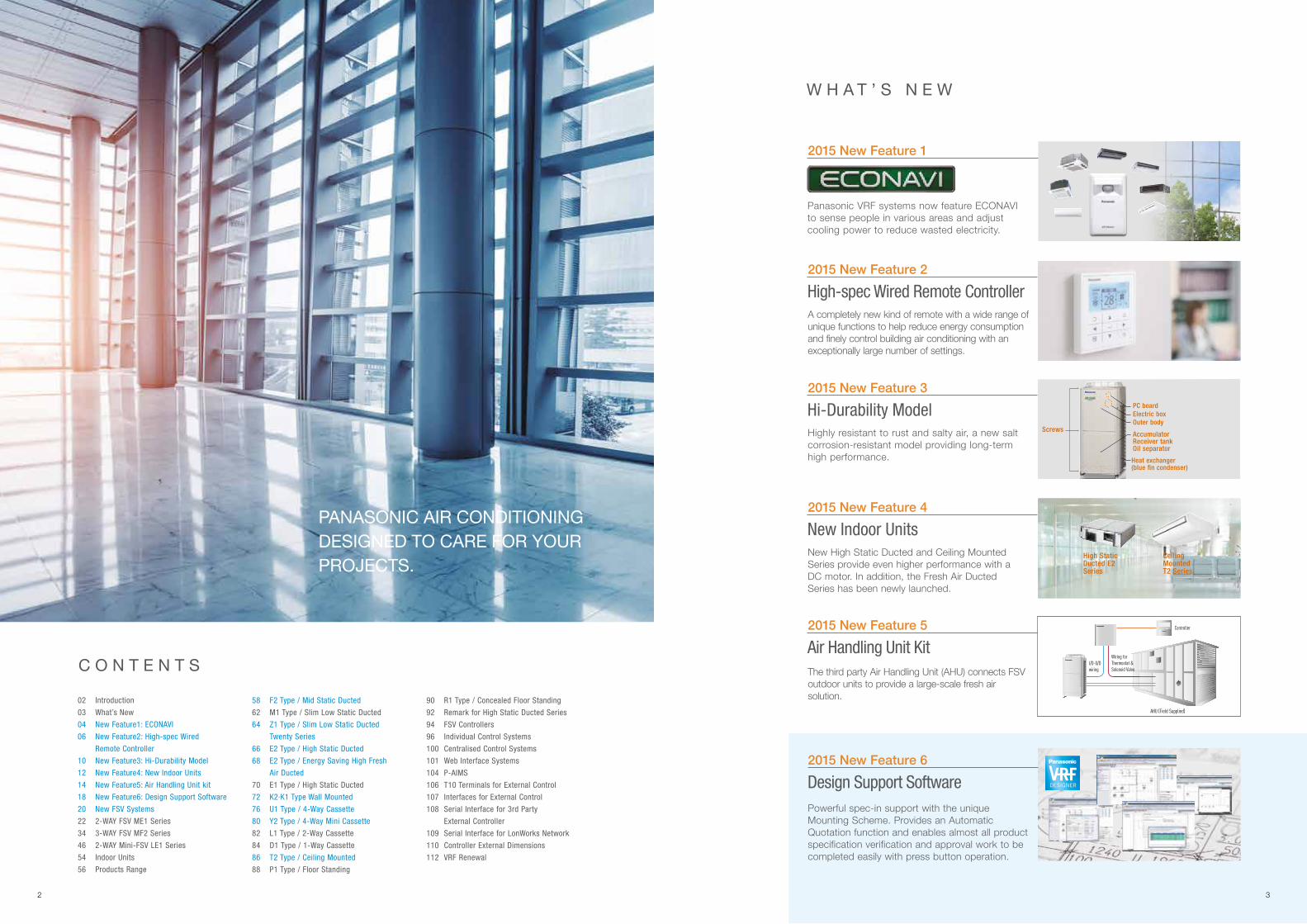
Panasonic VRF systems now feature ECONAVI to sense people in various areas and adjust cooling power to reduce wasted electricity.
2015 New Feature 1
2015 New Feature 4
2015 New Feature 6
2015 New Feature 3
2015 New Feature 2
2015 New Feature 5
New Indoor Units
Design Support Software
Hi-Durability Model
High-spec Wired Remote Controller
Air Handling Unit Kit
Mid Static Duct
Screws
High Static Ducted E2 Series
Ceiling MountedT2 Series
Electric box
Heat exchanger(blue fin condenser)
PC board
Outer body
AccumulatorReceiver tankOil separator
New High Static Ducted and Ceiling Mounted Series provide even higher performance with a DC motor. In addition, the Fresh Air Ducted Series has been newly launched.
Powerful spec-in support with the unique Mounting Scheme. Provides an Automatic Quotation function and enables almost all product specification verification and approval work to be completed easily with press button operation.
Highly resistant to rust and salty air, a new salt corrosion-resistant model providing long-term high performance.
A completely new kind of remote with a wide range of unique functions to help reduce energy consumption and finely control building air conditioning with an exceptionally large number of settings.
The third party Air Handling Unit (AHU) connects FSV outdoor units to provide a large-scale fresh air solution.
I/D-O/D wiring
Wiring for Thermostat & Solenoid Valve
Controller
AHU (Field Supplied)
3
PANASONIC AIR CONDITIONING DESIGNED TO CARE FOR YOUR PROJECTS.
C O N T E N T S
02 Introduction
03 What’s New
04 New Feature1: ECONAVI
06 New Feature2: High-spec Wired
Remote Controller
10 New Feature3: Hi-Durability Model
12 New Feature4: New Indoor Units
14 New Feature5: Air Handling Unit kit
18 New Feature6: Design Support Software
20 New FSV Systems
22 2-WAY FSV ME1 Series
34 3-WAY FSV MF2 Series
46 2-WAY Mini-FSV LE1 Series
54 Indoor Units
56 Products Range
58 F2 Type / Mid Static Ducted
62 M1 Type / Slim Low Static Ducted
64 Z1 Type / Slim Low Static Ducted
Twenty Series
66 E2 Type / High Static Ducted
68 E2 Type / Energy Saving High Fresh
Air Ducted
70 E1 Type / High Static Ducted
72 K2·K1 Type Wall Mounted
76 U1 Type / 4-Way Cassette
80 Y2 Type / 4-Way Mini Cassette
82 L1 Type / 2-Way Cassette
84 D1 Type / 1-Way Cassette
86 T2 Type / Ceiling Mounted
88 P1 Type / Floor Standing
90 R1 Type / Concealed Floor Standing
92 Remark for High Static Ducted Series
94 FSV Controllers
96 Individual Control Systems
100 Centralised Control Systems
101 Web Interface Systems
104 P-AIMS
106 T10 Terminals for External Control
107 Interfaces for External Control
108 Serial Interface for 3rd Party
External Controller
109 Serial Interface for LonWorks Network
110 Controller External Dimensions
112 VRF Renewal
2
Ceiling
A sensor is remotely set to maximise the detection area.
In the morningThorough cooling whenthere is a high level of activity
Reduced cooling whenthere are fewer people
At nightIn the afternoon
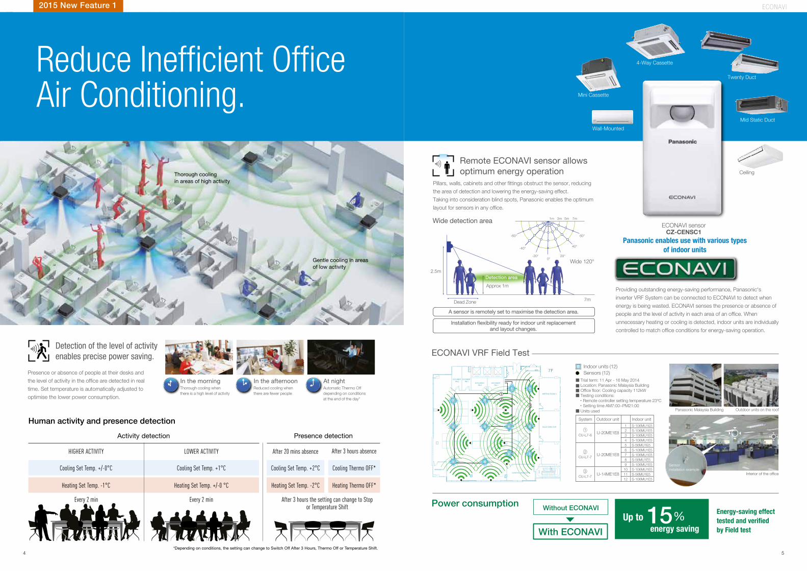
Providing outstanding energy-saving performance, Panasonic's
inverter VRF System can be connected to ECONAVI to detect when
energy is being wasted. ECONAVI senses the presence or absence of
people and the level of activity in each area of an office. When
unnecessary heating or cooling is detected, indoor units are individually
controlled to match office conditions for energy-saving operation.
Pillars, walls, cabinets and other fittings obstruct the sensor, reducing
the area of detection and lowering the energy-saving effect.
Taking into consideration blind spots, Panasonic enables the optimum
layout for sensors in any office.
Presence or absence of people at their desks and
the level of activity in the office are detected in real
time. Set temperature is automatically adjusted to
optimise the lower power consumption.
Approx 1m
Detection area
Dead Zone 7m
2.5m
-60°
1m 3m 5m 7m
60°
-40°
-20° 20°
40°
0°Wide 120°
Thorough coolingin areas of high activity
Gentle cooling in areasof low activity
Mid Static Duct
4-Way Cassette
Mini Cassette
Wall-Mounted
Twenty DuctReduce Inefficient OfficeAir Conditioning.
Detection of the level of activityenables precise power saving.
Remote ECONAVI sensor allows optimum energy operation
Panasonic enables use with various typesof indoor units
7F
3
2
1 MEETING ROOM 4
SALES DIRECTOR
GENERAL MANAGER 2
MANAGER 6
DOCUMENT RM.1
DOCUMENT RM.2
DOCUMENT RM.3
DOCUMENT RM.4 Trial term: 11 Apr - 16 May 2014
Location: Panasonic Malaysia Building Office floor: Cooling capacity 112kW Testing conditions: ・Remote controller setting temperature 23oC ・Setting time AM7:00~PM21:00
Units used
Indoor units (12)Sensors (12)
Panasonic Malaysia Building
Interior of the office
Outdoor units on the roof
Sensorinstallation example
System Outdoor unit Indoor unit
CU-L7-6U-20ME1E8
1 S-106MU1E52 S-106MU1E53 S-106MU1E54 S-106MU1E5
CU-L7-7U-20ME1E8
5 S-56MU1E56 S-106MU1E57 S-106MU1E58 S-56MU1E59 S-106MU1E5
CU-L7-7U-14ME1E8
10 S-106MU1E511 S-56MU1E512 S-106MU1E5
1
2
3
Wide detection area
ECONAVI VRF Field Test
Automatic Thermo Off depending on conditions at the end of the day*
ECONAVI sensorCZ-CENSC1
and layout changes.
15% Energy-saving effect tested and verifiedby Field test
Without ECONAVI
With ECONAVI
Power consumption
Up to energy saving
2015 New Feature 1
Human activity and presence detection
Activity detection
HIGHER ACTIVITY After 20 mins absence
Cooling Set Temp. +/-0°C Cooling Set Temp. +2°CCooling Set Temp. +1°C Cooling Thermo OFF*
Heating Set Temp. -1°C Heating Set Temp. -2°CHeating Set Temp. +/-0 °C Heating Thermo OFF*
Every 2 minEvery 2 min After 3 hours the setting can change to Stop or Temperature Shift
LOWER ACTIVITY After 3 hours absence
Presence detection
*Depending on conditions, the setting can change to Switch Off After 3 Hours, Thermo Off or Temperature Shift.
ECONAV I
4 5
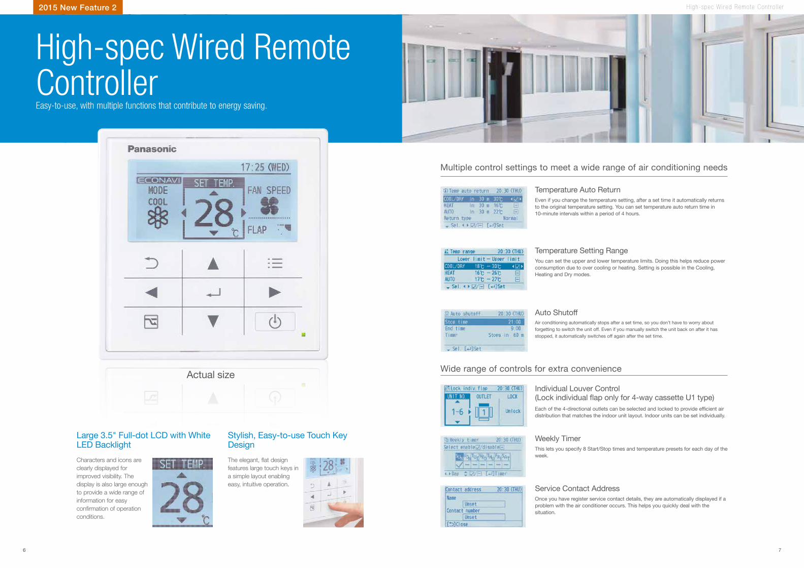
Temperature Auto Return
Temperature Setting Range
Auto Shutoff
Even if you change the temperature setting, after a set time it automatically returns to the original temperature setting. You can set temperature auto return time in 10-minute intervals within a period of 4 hours.
You can set the upper and lower temperature limits. Doing this helps reduce power consumption due to over cooling or heating. Setting is possible in the Cooling, Heating and Dry modes.
Air conditioning automatically stops after a set time, so you don’t have to worry about forgetting to switch the unit off. Even if you manually switch the unit back on after it has stopped, it automatically switches off again after the set time.
H igh-spec W i r ed Remo te Con t r o l l e r
Weekly Timer
Individual Louver Control
Service Contact Address
This lets you specify 8 Start/Stop times and temperature presets for each day of the week.
Each of the 4-directional outlets can be selected and locked to provide efficient air distribution that matches the indoor unit layout. Indoor units can be set individually.
Once you have register service contact details, they are automatically displayed if a problem with the air conditioner occurs. This helps you quickly deal with the situation.
Large 3.5" Full-dot LCD with White LED Backlight
Stylish, Easy-to-use Touch Key Design
Actual size
Characters and icons are clearly displayed for improved visibility. The display is also large enough to provide a wide range of information for easy con�rmation of operation conditions.
The elegant, �at design features large touch keys in a simple layout enabling easy, intuitive operation.
2015 New Feature 2
Multiple control settings to meet a wide range of air conditioning needs
Wide range of controls for extra convenience
Easy-to-use, with multiple functions that contribute to energy saving.
High-spec Wired Remote Controller
6 7
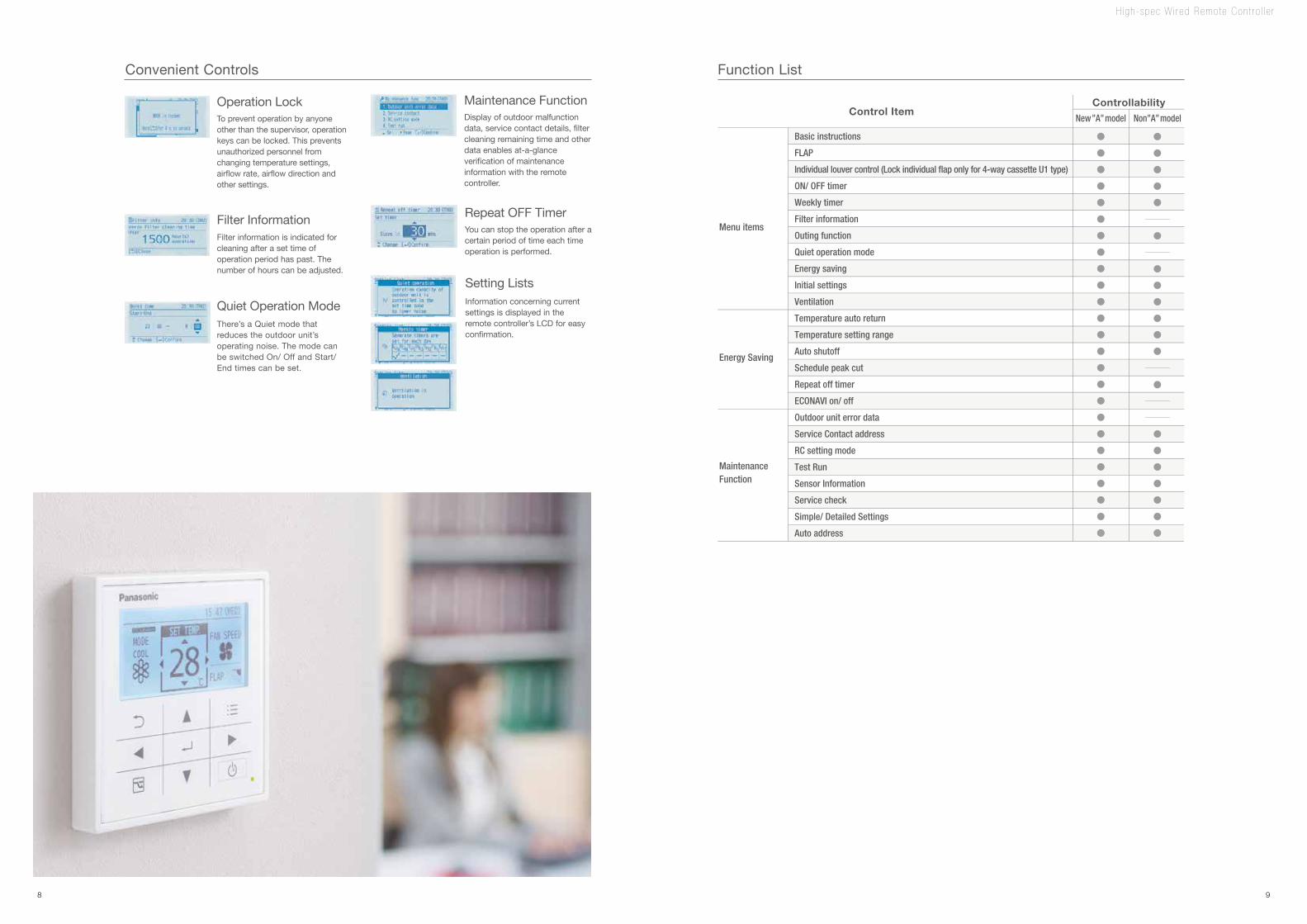
Menu items
Energy Saving
MaintenanceFunction
Control ItemControllability
New”A”model Non”A”model
Basic instructions
FLAP
Individual louver control (Lock individual flap only for 4-way cassette U1 type)
ON/ OFF timer
Weekly timer
Filter information
Outing function
Quiet operation mode
Energy saving
Initial settings
Ventilation
Temperature auto return
Temperature setting range
Auto shutoff
Schedule peak cut
Repeat off timer
ECONAVI on/ off
Outdoor unit error data
Service Contact address
RC setting mode
Test Run
Sensor Information
Service check
Simple/ Detailed Settings
Auto address
Operation Lock
Filter Information
Setting Lists
Maintenance Function
Quiet Operation Mode
To prevent operation by anyone other than the supervisor, operation keys can be locked. This prevents unauthorized personnel from changing temperature settings, airflow rate, airflow direction and other settings.
Display of outdoor malfunction data, service contact details, filter cleaning remaining time and other data enables at-a-glance verification of maintenance information with the remote controller.
There’s a Quiet mode that reduces the outdoor unit’s operating noise. The mode can be switched On/ Off and Start/End times can be set.
Filter information is indicated for cleaning after a set time of operation period has past. The number of hours can be adjusted.
Information concerning current settings is displayed in the remote controller’s LCD for easy confirmation.
H igh-spec W i r ed Remo te Con t r o l l e r
Repeat OFF TimerYou can stop the operation after a certain period of time each time operation is performed.
Convenient Controls Function List
8 9
H i -Du rab i l i t y Mode l
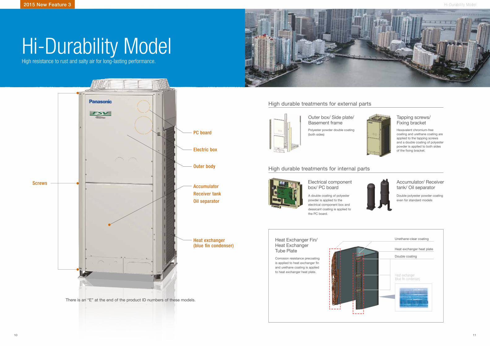
Polyester powder double coating (both sides)
Corrosion resistance precoating is applied to heat exchanger fin and urethane coating is applied to heat exchanger heat plate.
A double coating of polyester powder is applied to the electrical component box and dessicant coating is applied to the PC board.
Hexavalent chromium-free coating and urethane coating are applied to the tapping screws and a double coating of polyester powder is applied to both sides of the fixing bracket.
Double polyester powder coating even for standard models
ScrewsAccumulator
Receiver tank
Oil separator
Electric box
Heat exchanger(blue fin condenser)
Heat exchanger(blue �n condenser)
PC board
Outer body
Outer box/ Side plate/ Basement frame
Heat Exchanger Fin/ Heat Exchanger Tube Plate
Electrical component box/ PC board
Tapping screws/ Fixing bracket
Accumulator/ Receiver tank/ Oil separator
High resistance to rust and salty air for long-lasting performance.
Hi-Durability Model
2015 New Feature 3
There is an “E” at the end of the product ID numbers of these models.
Unethane-clear coating
Heat exchanger heat plate
Double coating
High durable treatments for external parts
High durable treatments for internal parts
10 11
New I ndoo r Un i t s
An expanded lineup to satisfy increasingly diverse air conditioning needs.
New Indoor Units
2015 New Feature 4
TYPE
TYPE
TYPE
High Static Ducted
Ceiling Mounted
Slim Ducted Twenty Series
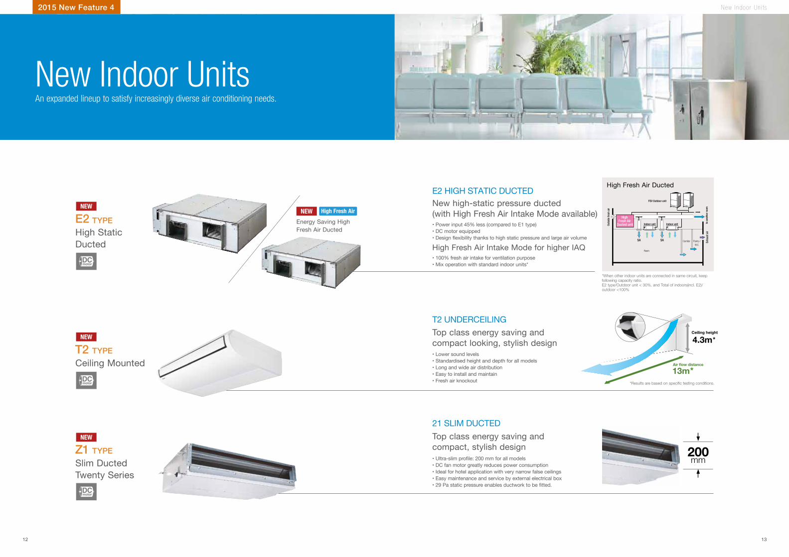
• Power input 45% less (compared to E1 type)• DC motor equipped• Design flexibility thanks to high static pressure and large air volume
E2
T2
Z1
New high-static pressure ducted (with High Fresh Air Intake Mode available)
• Lower sound levels• Standardised height and depth for all models• Long and wide air distribution• Easy to install and maintain• Fresh air knockout
• Ultra-slim profile: 200 mm for all models• DC fan motor greatly reduces power consumption• Ideal for hotel application with very narrow false ceilings• Easy maintenance and service by external electrical box• 29 Pa static pressure enables ductwork to be fitted.
Top class energy saving and compact looking, stylish design
Top class energy saving and compact, stylish design
FSV Outdoor unit
Indoor unit Indoor unit to a
noth
er ro
omEx
haus
t air
Outs
ide
fresh
air
Corridor Pantry /W.C.
SA SA
Room
High Fresh Air
Ducted unit
200mm
*When other indoor units are connected in same circuit, keep following capacity ratio.E2 type/Outdoor unit < 30%, and Total of indoors(incl. E2)/outdoor <100%
• 100% fresh air intake for ventilation purpose • Mix operation with standard indoor units*
High Fresh Air Intake Mode for higher IAQ
High Fresh Air Ducted
Energy Saving High Fresh Air Ducted
NEW
NEW
NEW
NEW
DCmotor
DCmotor
DCmotor
High Fresh Air
12 13
E2 HIGH STATIC DUCTED
T2 UNDERCEILING
21 SLIM DUCTED
13m
4.3m
Air �ow distance
Ceiling height
*
**Results are based on speci�c testing conditions.
A i r Hand l i ng Un i t2015 New Feature 5
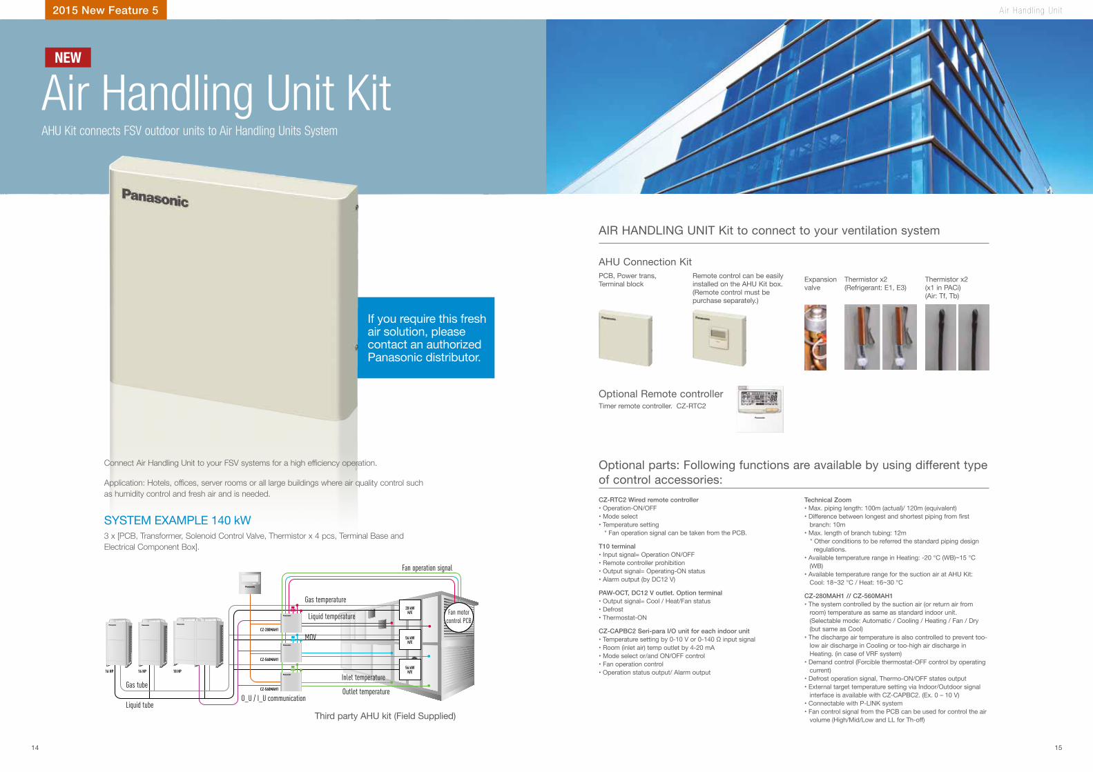
AHU Kit connects FSV outdoor units to Air Handling Units System
PCB, Power trans, Terminal block
AHU Connection Kit
Optional Remote controllerTimer remote controller. CZ-RTC2
Remote control can be easily installed on the AHU Kit box. (Remote control must be purchase separately.)
Expansion valve
Thermistor x2(Refrigerant: E1, E3)
Thermistor x2 (x1 in PACi)(Air: Tf, Tb)
Application: Hotels, of�ces, server rooms or all large buildings where air quality control such as humidity control and fresh air and is needed.
If you require this fresh air solution, please contact an authorized Panasonic distributor.
Connect Air Handling Unit to your FSV systems for a high ef�ciency operation.
3 x [PCB, Transformer, Solenoid Control Valve, Thermistor x 4 pcs, Terminal Base and Electrical Component Box].
Third party AHU kit (Field Supplied)
16 HP 16 HP 18 HP
28 kWH/E
56 kWH/E
56 kWH/E
CZ-280MAH1
CZ-560MAH1
CZ-560MAH1
SYSTEM EXAMPLE 140 kW
Liquid tube
MOV
Gas temperature
Fan operation signal
Fan motorcontrol PCB
Inlet temperature
Outlet temperatureO_U / I_U communication
Gas tube
Liquid temperature
CZ-RTC2 Wired remote controller• Operation-ON/OFF• Mode select• Temperature setting * Fan operation signal can be taken from the PCB.
T10 terminal • Input signal= Operation ON/OFF• Remote controller prohibition• Output signal= Operating-ON status• Alarm output (by DC12 V)
PAW-OCT, DC12 V outlet. Option terminal• Output signal= Cool / Heat/Fan status• Defrost• Thermostat-ON
CZ-CAPBC2 Seri-para I/O unit for each indoor unit • Temperature setting by 0-10 V or 0-140 Ω input signal• Room (inlet air) temp outlet by 4-20 mA• Mode select or/and ON/OFF control• Fan operation control• Operation status output/ Alarm output
Technical Zoom• Max. piping length: 100m (actual)/ 120m (equivalent)• Difference between longest and shortest piping from first
branch: 10m• Max. length of branch tubing: 12m * Other conditions to be referred the standard piping design regulations.• Available temperature range in Heating: -20 °C (WB)~15 °C
(WB)• Available temperature range for the suction air at AHU Kit:
Cool: 18~32 °C / Heat: 16~30 °C
CZ-280MAH1 // CZ-560MAH1• The system controlled by the suction air (or return air from
room) temperature as same as standard indoor unit. (Selectable mode: Automatic / Cooling / Heating / Fan / Dry (but same as Cool)
• The discharge air temperature is also controlled to prevent too-low air discharge in Cooling or too-high air discharge in Heating. (in case of VRF system)
• Demand control (Forcible thermostat-OFF control by operating current)
• Defrost operation signal, Thermo-ON/OFF states output• External target temperature setting via Indoor/Outdoor signal
interface is available with CZ-CAPBC2. (Ex. 0 – 10 V)• Connectable with P-LINK system• Fan control signal from the PCB can be used for control the air
volume (High/Mid/Low and LL for Th-off)
Air Handling Unit KitNEW
Optional parts: Following functions are available by using different type of control accessories:
AIR HANDLING UNIT Kit to connect to your ventilation system
14 15
AHU CONNECTION KIT, 28 kW AND 56 kW FOR FSV
Cooling capacity
Heating capacity Horsepower
Cooling Air�ow
Bypass Factor
Dimensions of the box
Piping lengthElevation diff. (in/out)
Pipe DiametersIntake temperature of AHU Kit
Ambient temperature of outdoor unit
Nominal Nominal Max / Min H x W x D Min / Max Max Liquid pipe Gas pipe Min / Max Min / Max
kW kW HP m³/min mm m m Inch (mm) Inch (mm) °C °C
CZ-280MAH1 28.0 31.5 10 5,000 / 3,500 0.9 (recommended) 404 x 425 x 78 10 / 100 50 3/8 (9.52) 7/8 (22.22)
Cooling:18 - 32DB (13 - 23 WB) / Heating:16 - 30 DB
Cooling: -10 - 43 DB / Heating: -20 - 15 WB
CZ-560MAH1 56.0 63.0 20 10,000 / 7,000 0.9 (recommended) 404 x 425 x 78 10 / 100 50 5/8 (15.88) 1 1/8 (28.58)
CZ-280MAH1 + CZ-560MAH1 84.0 95.0 30 15,000 / 10,500 0.9 (recommended) 404 x 425 x 78 10 / 100 50 3/4 (19.05) 1 1/4 (31.75)
CZ-560MAH1 x2 112.0 127.0 40 20,000 / 14,000 0.9 (recommended) 404 x 425 x 78 10 / 100 50 3/4 (19.05) 1 1/2 (38.15)
CZ-560MAH1 x2 + CZ-280MAH1 140.0 155.0 50 25,000 / 17,500 0.9 (recommended) 404 x 425 x 78 10 / 100 50 3/4 (19.05) 1 1/2 (38.15)
CZ-560MAH1 x3 168.0 189.0 60 30,000 / 21,000 0.9 (recommended) 404 x 425 x 78 10 / 100 50 3/4 (19.05) 1 1/2 (38.15)
AHU Connection Kit / System Combination
Capacity (HP) Outdoor unit combination AHU kit combination
2-Way FSV ME1 SERIES
28 kW (10 HP) U-10MER8B CZ-280MAH1
56 kW (20 HP) U-20MER8B CZ-560MAH1
84 kW (30 HP) U-16MER8B U-14MER8B CZ-560MAH1 CZ-280MAH1
112 kW (40 HP) U-20MER8B U-20MER8B CZ-560MAH1 CZ-560MAH1
140 kW (50 HP) U-18MER8B U-16MER8B U-16MER8B CZ-560MAH1 CZ-560MAH1 CZ-280MAH1
168 kW (60 HP) U-20MER8B U-20MER8B U-20MER8B CZ-560MAH1 CZ-560MAH1 CZ-560MAH1
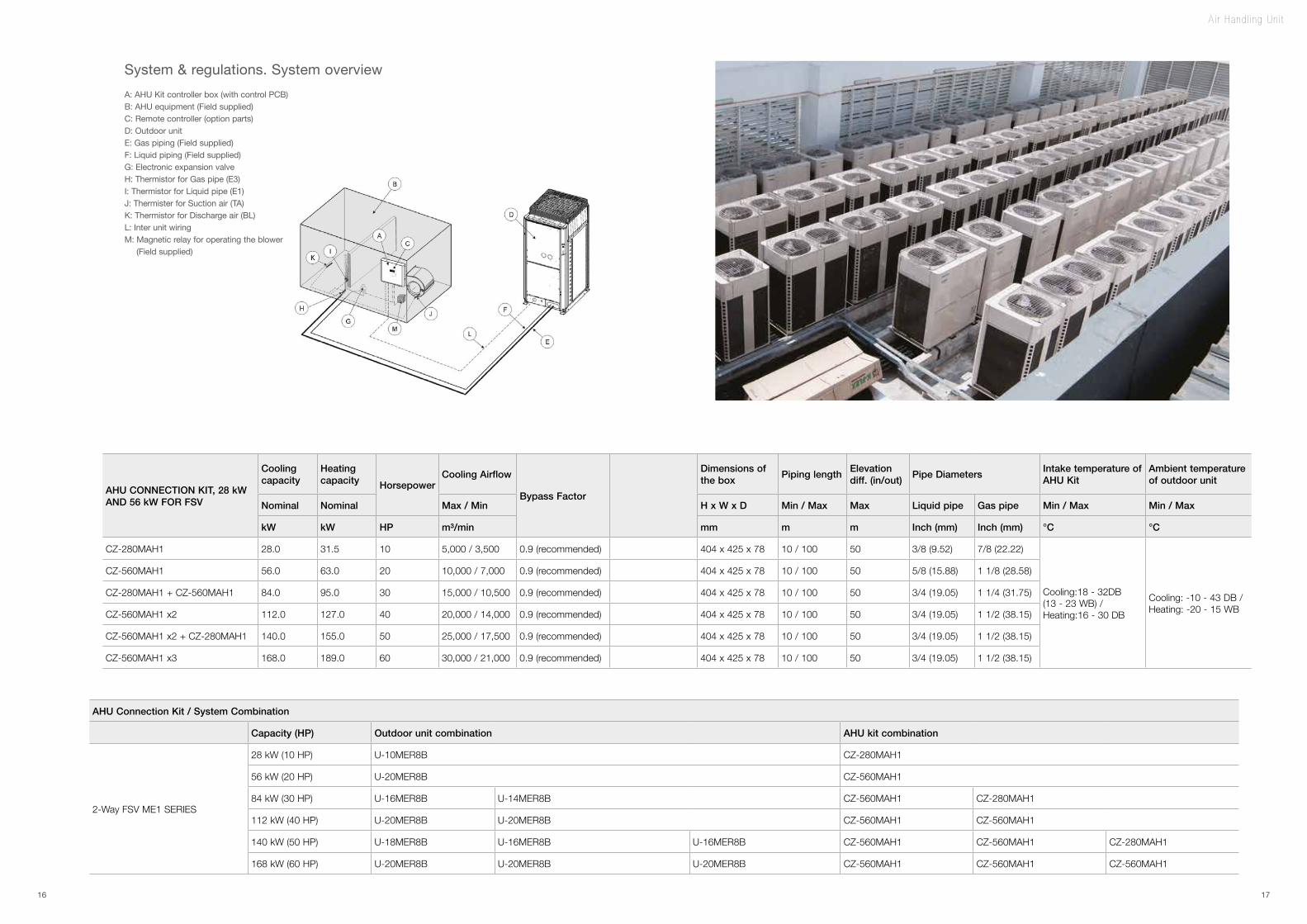
A: AHU Kit controller box (with control PCB)B: AHU equipment (Field supplied)C: Remote controller (option parts)D: Outdoor unitE: Gas piping (Field supplied)F: Liquid piping (Field supplied)G: Electronic expansion valveH: Thermistor for Gas pipe (E3)I: Thermistor for Liquid pipe (E1)J: Thermister for Suction air (TA)K: Thermistor for Discharge air (BL)L: Inter unit wiringM: Magnetic relay for operating the blower (Field supplied)
System & regulations. System overview
A i r Hand l i ng Un i t
16 17
Des i gn Suppo r t So f twa re
Design Support Software for FSV
Features include
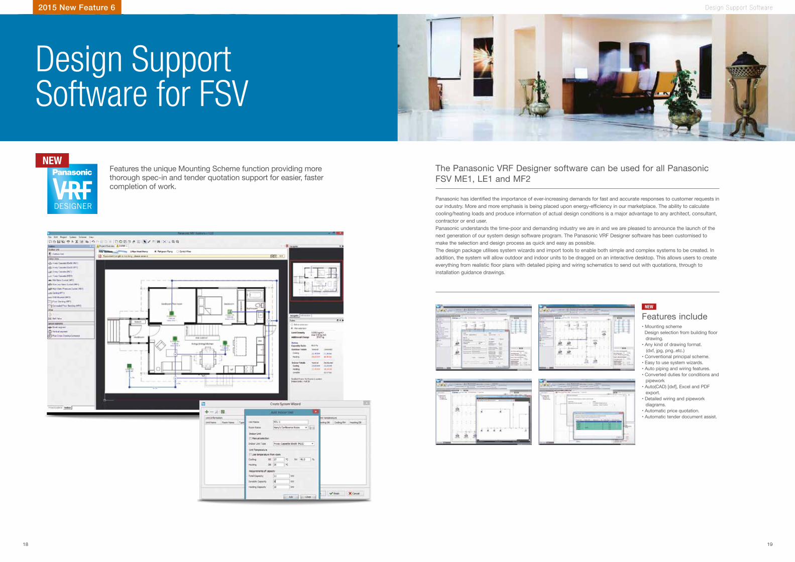
Panasonic has identified the importance of ever-increasing demands for fast and accurate responses to customer requests in our industry. More and more emphasis is being placed upon energy-efficiency in our marketplace. The ability to calculate cooling/heating loads and produce information of actual design conditions is a major advantage to any architect, consultant, contractor or end user.Panasonic understands the time-poor and demanding industry we are in and we are pleased to announce the launch of the next generation of our system design software program. The Panasonic VRF Designer software has been customised to make the selection and design process as quick and easy as possible.The design package utilises system wizards and import tools to enable both simple and complex systems to be created. In addition, the system will allow outdoor and indoor units to be dragged on an interactive desktop. This allows users to create everything from realistic floor plans with detailed piping and wiring schematics to send out with quotations, through to installation guidance drawings.
The Panasonic VRF Designer software can be used for all Panasonic FSV ME1, LE1 and MF2
• Mounting scheme Design selection from building floor
drawing.• Any kind of drawing format. (dxf, jpg, png..etc.)• Conventional principal scheme.• Easy to use system wizards.• Auto piping and wiring features.• Converted duties for conditions and
pipework• Auto(CAD) [dxf], Excel and PDF
export.• Detailed wiring and pipework
diagrams.• Automatic price quotation.• Automatic tender document assist.
2015 New Feature 6
Features the unique Mounting Scheme function providing more thorough spec-in and tender quotation support for easier, faster completion of work.
NEW
NEW
18 19
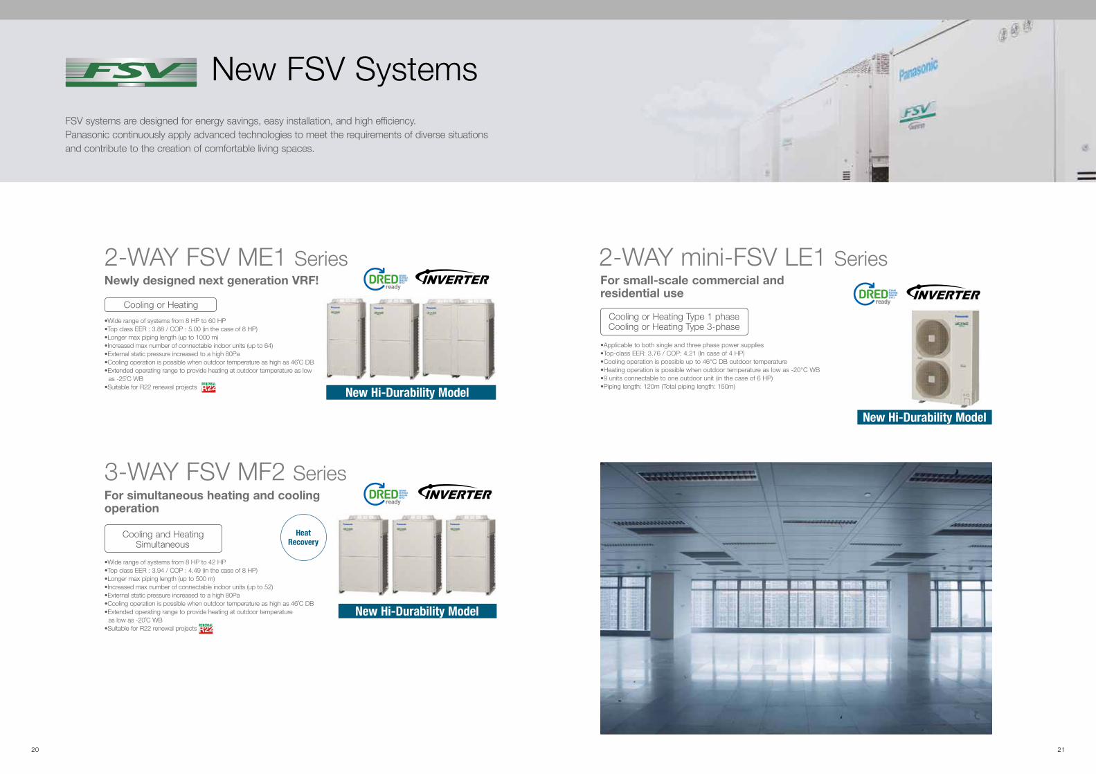
FSV systems are designed for energy savings, easy installation, and high ef�ciency. Panasonic continuously apply advanced technologies to meet the requirements of diverse situations and contribute to the creation of comfortable living spaces.
New FSV Systems
2-WAY FSV ME1 SeriesNewly designed next generation VRF!
Cooling or Heating
•Applicable to both single and three phase power supplies•Top-class EER: 3.76 / COP: 4.21 (In case of 4 HP)•Cooling operation is possible up to 46°C DB outdoor temperature•Heating operation is possible when outdoor temperature as low as -20°C WB•9 units connectable to one outdoor unit (in the case of 6 HP) •Piping length: 120m (Total piping length: 150m)
2-WAY mini-FSV LE1 SeriesFor small-scale commercial and residential use
Cooling or Heating Type 1 phaseCooling or Heating Type 3-phase
•Wide range of systems from 8 HP to 42 HP •Top class EER : 3.94 / COP : 4.49 (in the case of 8 HP)•Longer max piping length (up to 500 m)•Increased max number of connectable indoor units (up to 52)•External static pressure increased to a high 80Pa•Cooling operation is possible when outdoor temperature as high as 46˚C DB•Extended operating range to provide heating at outdoor temperature
as low as -20˚C WB•Suitable for R22 renewal projects
3-WAY FSV MF2 SeriesFor simultaneous heating and cooling operation
Cooling and Heating Simultaneous
Heat Recovery
New Hi-Durability Model
New Hi-Durability Model
New Hi-Durability Model
•Wide range of systems from 8 HP to 60 HP •Top class EER : 3.88 / COP : 5.00 (in the case of 8 HP)•Longer max piping length (up to 1000 m)•Increased max number of connectable indoor units (up to 64)•External static pressure increased to a high 80Pa•Cooling operation is possible when outdoor temperature as high as 46˚C DB•Extended operating range to provide heating at outdoor temperature as low
as -25˚C WB•Suitable for R22 renewal projects
20 21
Series2-WAY FSV ME1High-ef�ciency & large-capacity VRF system
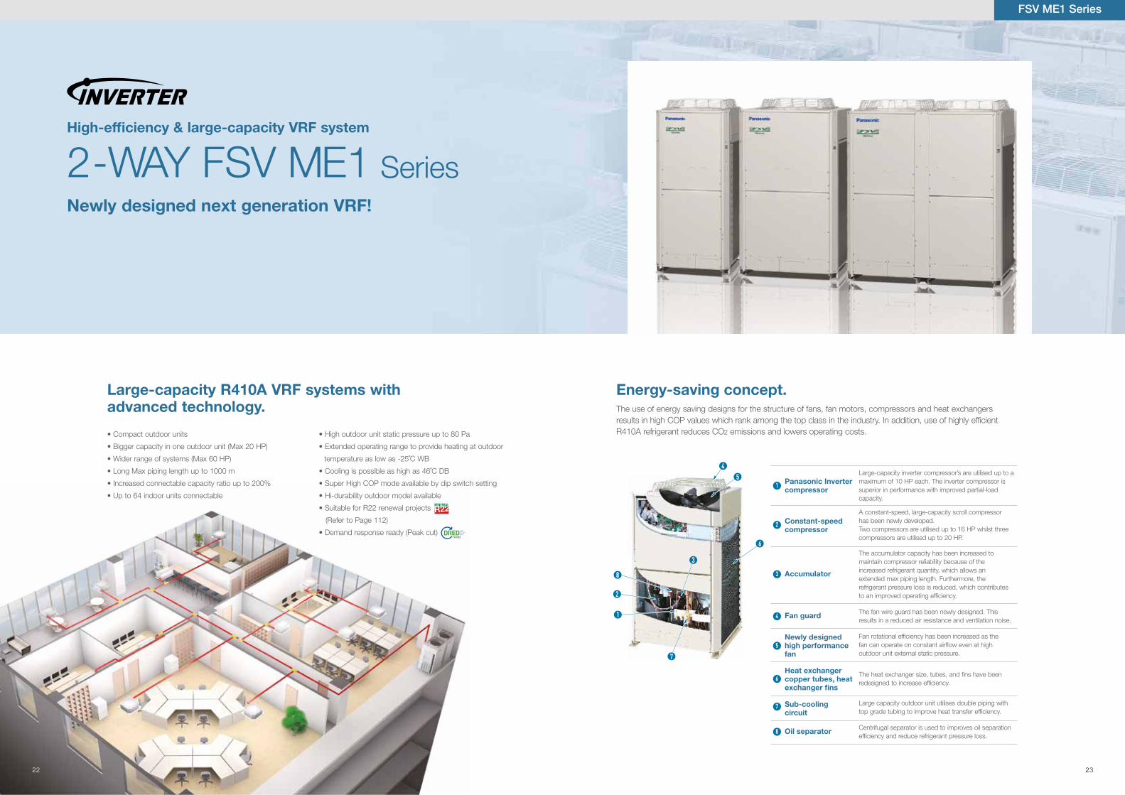
The use of energy saving designs for the structure of fans, fan motors, compressors and heat exchangersresults in high COP values which rank among the top class in the industry. In addition, use of highly ef�cientR410A refrigerant reduces CO2 emissions and lowers operating costs.
Energy-saving concept.Large-capacity R410A VRF systems with advanced technology.
Newly designed next generation VRF!
Large-capacity inverter compressor’s are utilised up to a maximum of 10 HP each. The inverter compressor is superior in performance with improved partial-load capacity.
A constant-speed, large-capacity scroll compressorhas been newly developed.Two compressors are utilised up to 16 HP whilst threecompressors are utilised up to 20 HP.
The accumulator capacity has been increased tomaintain compressor reliability because of theincreased refrigerant quantity, which allows anextended max piping length. Furthermore, therefrigerant pressure loss is reduced, which contributesto an improved operating ef�ciency.
The fan wire guard has been newly designed. Thisresults in a reduced air resistance and ventilation noise.
Fan rotational ef�ciency has been increased as thefan can operate on constant air�ow even at highoutdoor unit external static pressure.
The heat exchanger size, tubes, and �ns have beenredesigned to increase ef�ciency.
Large capacity outdoor unit utilises double piping withtop grade tubing to improve heat transfer ef�ciency.
Panasonic Inverter compressor
Constant-speed compressor
Accumulator
Fan guard
Newly designedhigh performance fan
Heat exchanger copper tubes, heat exchanger fins
Sub-cooling circuit
Centrifugal separator is used to improves oil separation ef�ciency and reduce refrigerant pressure loss.
Oil separator
3
45
6
2
1
8
7
1
2
3
4
5
6
7
8
• High outdoor unit static pressure up to 80 Pa
• Extended operating range to provide heating at outdoor
temperature as low as -25˚C WB
• Cooling is possible as high as 46˚C DB
• Super High COP mode available by dip switch setting
• Hi-durability outdoor model available
• Suitable for R22 renewal projects
(Refer to Page 112)
• Demand response ready (Peak cut)
• Compact outdoor units
• Bigger capacity in one outdoor unit (Max 20 HP)
• Wider range of systems (Max 60 HP)
• Long Max piping length up to 1000 m
• Increased connectable capacity ratio up to 200%
• Up to 64 indoor units connectable
FSV ME1 Series
22 23
Up to 64 Indoor Units Connectable!*
High-ef�ciency & large-capacity VRF system
2-WAY FSV ME1 Series
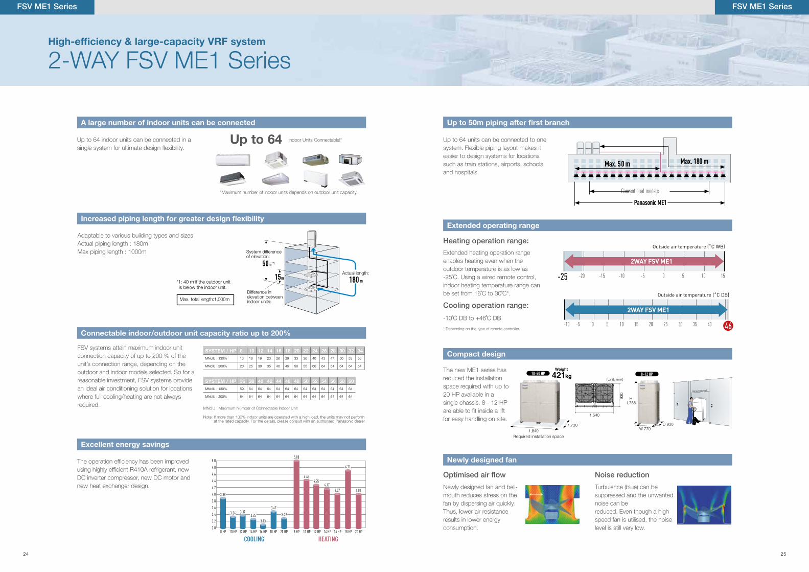
Up to 64 indoor units can be connected in asingle system for ultimate design �exibility.
Up to 64 units can be connected to one system. Flexible piping layout makes it easier to design systems for locations such as train stations, airports, schools and hospitals.
Extended heating operation rangeenables heating even when theoutdoor temperature is as low as-25˚C. Using a wired remote control,indoor heating temperature range canbe set from 16˚C to 30˚C*.
-10˚C DB to +46˚C DB
Adaptable to various building types and sizesActual piping length : 180mMax piping length : 1000m
The operation ef�ciency has been improvedusing highly ef�cient R410A refrigerant, newDC inverter compressor, new DC motor andnew heat exchanger design.
Heating operation range:
Cooling operation range:
Noise reduction
5.0
4.8
4.6
4.4
4.2
4.0
3.8
3.6
3.4
3.2
3.08 HP 10 HP 12 HP 14 HP 16 HP
COOLING
5.00
8 HP 10 HP 12 HP 14 HP 16 HP
HEATING18 HP 20 HP18 HP 20 HP
4.64.54.4
4.45 4.454.41 4.39
4.524.50
HIGH COP SETTING MODEL
3.88
3.34 3.373.25
3.13
4.424.25
4.174.07
4.71
4.01
3.47
3.29
3.88
3.34 3.373.25
3.13
4.424.25
4.174.07
4.71
4.01
3.47
3.29
Conventional models
Panasonic ME1
Max. 180 mMax. 50 m
Weight
Required installation space
1,7301,840
421kg18 -20 HP
H1,758
W 770D 930
8 -12 HP
930
1,540
(Unit: mm)
Weight
Required installation space
1,7301,840
421kg18 -20 HP
H1,758
W 770D 930
8 -12 HP
930
1,540
(Unit: mm)
-15 -10-25 -20 -5 100 5 15
Outside air temperature (˚C WB)
2WAY FSV ME1
460 5-10 -5 10 2515 20 30 35 40
Outside air temperature (˚C DB)
2WAY FSV ME1
*Maximum number of indoor units depends on outdoor unit capacity.
*1: 40 m if the outdoor unit is below the indoor unit.
Max. total length:1,000m
The new ME1 series has reduced the installation space required with up to 20 HP available in a single chassis. 8 - 12 HP are able to �t inside a lift for easy handling on site.
Newly designed fan and bell-mouth reduces stress on the fan by dispersing air quickly. Thus, lower air resistance results in lower energy consumption.
Turbulence (blue) can be suppressed and the unwanted noise can bereduced. Even though a high speed fan is utilised, the noise level is still very low.
Actual length:
180 m15 m
50 m *1
Difference in elevation between indoor units:
System difference of elevation:
A large number of indoor units can be connected Up to 50m piping after first branch
Extended operating range
Compact design
Newly designed fan
Increased piping length for greater design flexibility
Excellent energy savings
FSV ME1 Series
FSV systems attain maximum indoor unit connection capacity of up to 200 % of the unit’s connection range, depending on the outdoor and indoor models selected. So for a reasonable investment, FSV systems provide an ideal air conditioning solution for locations where full cooling/heating are not always required.
MNcIU : Maximum Number of Connectable Indoor Unit
Note: If more than 100% indoor units are operated with a high load, the units may not perform at the rated capacity. For the details, please consult with an authorised Panasonic dealer
SYSTEM / HP 8 10 12 14 16 18 20 22 24 26 28 30 32 34
MNcIU : 130% 13 16 19 23 26 29 33 36 40 43 47 50 53 56
MNcIU : 200% 20 25 30 35 40 45 50 55 60 64 64 64 64 64
SYSTEM / HP 36 38 40 42 44 46 48 50 52 54 56 58 60
MNcIU : 130% 59 64 64 64 64 64 64 64 64 64 64 64 64
MNcIU : 200% 64 64 64 64 64 64 64 64 64 64 64 64 64
Connectable indoor/outdoor unit capacity ratio up to 200%
FSV ME1 Series
* Depending on the type of remote controller.
24 25
High-ef�ciency & large-capacity VRF system
2-WAY FSV ME1 Series
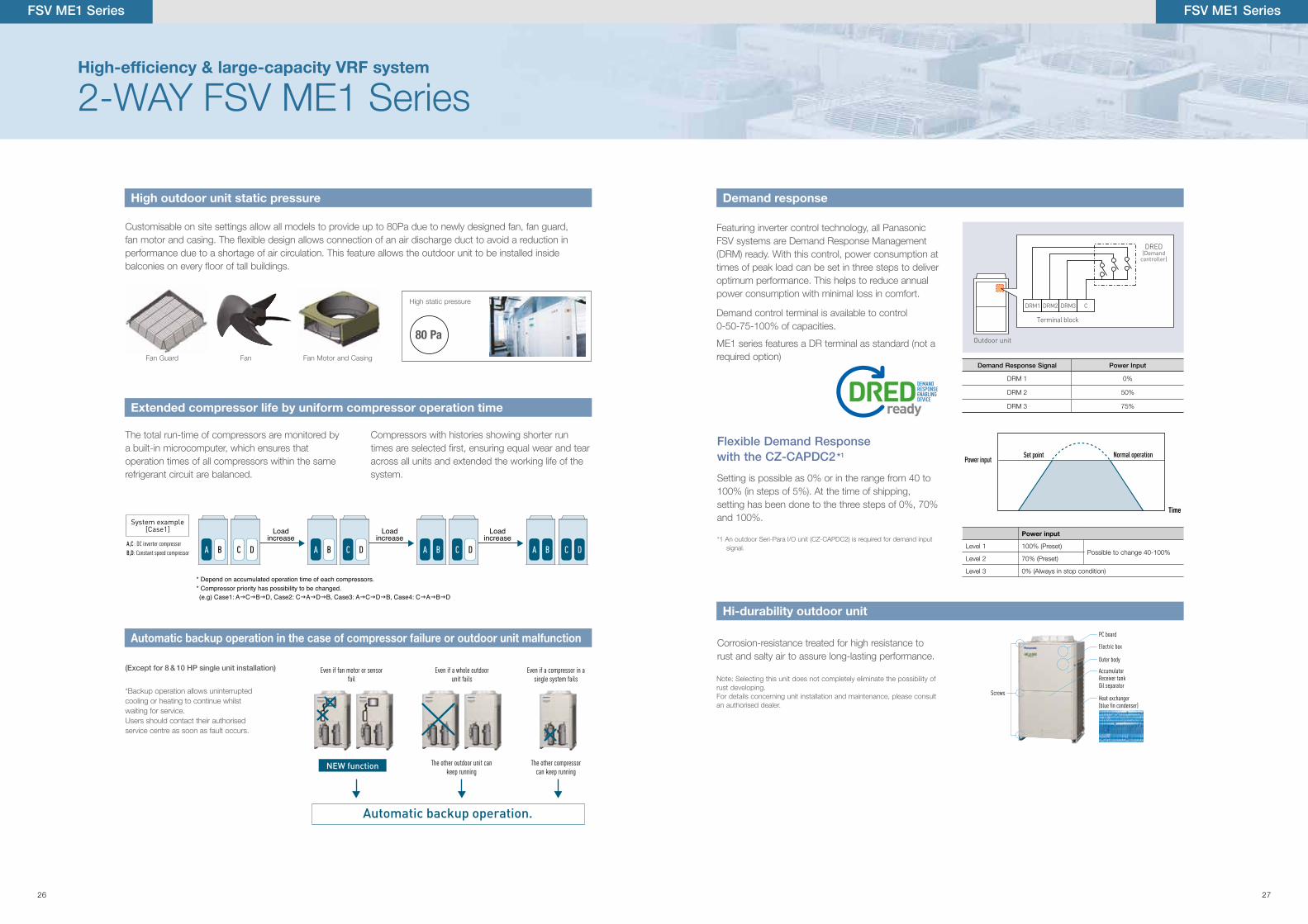
Customisable on site settings allow all models to provide up to 80Pa due to newly designed fan, fan guard,fan motor and casing. The �exible design allows connection of an air discharge duct to avoid a reduction inperformance due to a shortage of air circulation. This feature allows the outdoor unit to be installed insidebalconies on every �oor of tall buildings.
*Backup operation allows uninterrupted cooling or heating to continue whilst waiting for service.Users should contact their authorised service centre as soon as fault occurs.
The total run-time of compressors are monitored by a built-in microcomputer, which ensures that operation times of all compressors within the same refrigerant circuit are balanced.
Compressors with histories showing shorter run times are selected �rst, ensuring equal wear and tear across all units and extended the working life of the system.
Fan Guard Fan Fan Motor and Casing
High outdoor unit static pressure
Automatic backup operation in the case of compressor failure or outdoor unit malfunction
Extended compressor life by uniform compressor operation time
(Except for 8 & 10 HP single unit installation) Even if fan motor or sensorfail
Even if a compressor in asingle system fails
Even if a whole outdoorunit fails
The other compressor can keep running
The other outdoor unit can keep running
Automatic backup operation.
NEW function
FSV ME1 Series
Hi-durability outdoor unit
FSV ME1 Series
Screws
PC board
Electric box
Outer body
AccumulatorReceiver tankOil separator
Heat exchanger (blue fin condenser)
Corrosion-resistance treated for high resistance to rust and salty air to assure long-lasting performance.
Note: Selecting this unit does not completely eliminate the possibility of rust developing. For details concerning unit installation and maintenance, please consult an authorised dealer.
High static pressure
80 Pa
Setting is possible as 0% or in the range from 40 to 100% (in steps of 5%). At the time of shipping, setting has been done to the three steps of 0%, 70% and 100%.
Flexible Demand Response with the CZ-CAPDC2*1
*1 An outdoor Seri-Para l/O unit (CZ-CAPDC2) is required for demand input signal.
Power input
Level 1 100% (Preset)Possible to change 40-100%
Level 2 70% (Preset)
Level 3 0% (Always in stop condition)
Set point
Time
Normal operationPower input
Demand response
Featuring inverter control technology, all Panasonic FSV systems are Demand Response Management (DRM) ready. With this control, power consumption at times of peak load can be set in three steps to deliver optimum performance. This helps to reduce annual power consumption with minimal loss in comfort.
Outdoor unit
CDRM1 DRM2 DRM3
Terminal block
Current input is DC 24 V 10 mA
DRED (Demand
controller)Relay contact
point:No voltage relay
Demand control terminal is available to control 0-50-75-100% of capacities.
ME1 series features a DR terminal as standard (not a required option)
Demand Response Signal Power Input
DRM 1 0%
DRM 2 50%
DRM 3 75%
* Depend on accumulated operation time of each compressors.* Compressor priority has possibility to be changed.
A,C : DC inverter compressor
B,D: Constant speed compressor
System example[Case1]
A B C D A B C D A B C D A B C D
Loadincrease
Loadincrease
Loadincrease
(e.g) Case1: AgCgBgD, Case2: CgAgDgB, Case3: AgCgDgB, Case4: CgAgBgD
26 27

2-WAY FSV ME1 Series
Appearance
HP 8 10 12 14 16 18 20 22 24 26 28 30 32 34 36 38 40 42 44 46 48 50 52 54 56 58 60
Model name U-8ME1R8B U-10ME1R8B U-12ME1R8B U-14ME1R8B U-16ME1R8B U-18ME1R8B U-20ME1R8B U-14ME1R8BU-8ME1R8B
U-14ME1R8BU-10ME1R8B
U-14ME1R8BU-12ME1R8B
U-16ME1R8BU-12ME1R8B
U-16ME1R8BU-14ME1R8B
U-16ME1R8BU-16ME1R8B
U-18ME1R8BU-16ME1R8B
U-20ME1R8BU-16ME1R8B
U-20ME1R8BU-18ME1R8B
U-20ME1R8BU-20ME1R8B
U-16ME1R8BU-14ME1R8BU-12ME1R8B
U-16ME1R8BU-16ME1R8BU-12ME1R8B
U-16ME1R8BU-16ME1R8BU-14ME1R8B
U-16ME1R8BU-16ME1R8BU-16ME1R8B
U-18ME1R8BU-16ME1R8BU-16ME1R8B
U-20ME1R8BU-16ME1R8BU-16ME1R8B
U-20ME1R8BU-18ME1R8BU-16ME1R8B
U-20ME1R8BU-18ME1R8BU-18ME1R8B
U-20ME1R8BU-20ME1R8BU-18ME1R8B
U-20ME1R8BU-20ME1R8BU-20ME1R8B
Power supply 415V/3-phase/50Hz 415V 3-phase/50Hz 415V 3-phase/50Hz
Capacity
CoolingkW 22.4 28.0 32.8 40.0 42.5 50.0 56.0 61.5 68.0 73.0 78.5 85.0 90.0 96.0 101.0 107.0 113.0 118.0 124.0 130.0 135.0 140.0 145.0 151.0 156.0 162.0 168.0
BTU/h 76,500 95,600 112,000 136,500 145,100 170,600 191,100 209,900 232,100 249,100 267,900 290,100 307,200 327,600 344,700 365,200 385,700 402,700 423,200 443,700 460,800 477,800 494,900 515,400 532,400 552,900 573,400
HeatingkW 25.0 31.5 37.5 45.0 49.7 56.0 63.0 69.0 76.5 81.5 87.5 95.0 100.0 108.0 113.0 119.0 127.0 132.0 138.0 145.0 150.0 155.0 160.0 169.0 175.0 182.0 189.0
BTU/h 85,300 107,500 128,000 153,600 169,600 191,100 215,000 235,500 261,100 278,200 298,600 324,200 341,300 368,600 385,700 406,100 433,400 450,500 471,000 494,900 511,900 529,000 546,100 576,800 597,300 621,200 645,100
EER / COPCooling W/W 3.88 3.34 3.37 3.25 3.13 3.47 3.29 3.47 3.29 3.30 3.17 3.15 3.05 3.25 3.19 3.36 3.28 3.20 3.12 3.11 3.05 3.20 3.15 3.28 3.41 3.35 3.29
Heating W/W 5.00 4.42 4.25 4.17 4.07 4.71 4.01 4.45 4.27 4.22 4.15 4.11 4.07 4.34 4.04 4.31 3.99 4.15 4.11 4.10 4.07 4.28 4.08 4.24 4.43 4.20 4.01
Dimensions H x W x D mm 1,758 x 770 x 930
1,758 x 770 x 930
1,758 x 770 x 930
1,758 x 1,000 x 930
1,758 x 1,000 x 930
1,758 x 1,540 x 930
1,758 x 1,540 x 930
1,758 x 1,830 x 930
1,758 x 1,830 x 930
1,758 x 1,830 x 930
1,758 x 1,830 x 930
1,758 x 2,060 x 930
1,758 x 2,060 x 930
1,758 x 2,600 x 930
1,758 x 2,600 x 930
1,758 x 3,140 x 930
1,758 x 3,140 x 930
1,758 x 2,890 x 930
1,758 x 2,890 x 930
1,758 x 3,120 x 930
1,758 x 3,120 x 930
1,758 x 3,660 x 930
1,758 x 3,660 x 930
1,758 x 4,200 x 930
1,758 x 4,740 x 930
1,758 x 4,740 x 930
1,758 x 4,740 x 930
Net weight kg 234 234 281 309 309 421 421 543 543 590 590 618 618 730 730 842 842 899 899 927 927 1,039 1,039 1,151 1,263 1,263 1,263
Electrical ratings
CoolingRunning current A 8.73 12.4 14.7 18.8 20.6 22.3 26.3 26.8 31.0 33.4 37.5 40.8 44.6 45.1 48.5 49.2 53.3 55.8 60.0 63.2 66.8 66.2 69.6 70.5 70.8 74.8 78.8
Power input kW 5.77 8.39 9.74 12.3 13.6 14.4 17.0 17.7 20.7 22.1 24.8 27.0 29.5 29.5 31.7 31.8 34.5 36.9 39.7 41.8 44.2 43.8 46.0 46.1 45.8 48.4 51.0
HeatingRunning current A 7.64 10.7 13.6 16.7 18.9 18.6 24.5 23.7 27.1 29.8 32.6 35.7 38.0 38.5 43.3 43.1 49.7 49.2 51.9 54.7 57.0 56.0 60.6 61.7 61.7 67.7 73.6
Power input kW 5.00 7.12 8.82 10.8 12.2 11.9 15.7 15.5 17.9 19.3 21.1 23.1 24.6 24.9 28.0 27.6 31.8 31.8 33.6 35.4 36.9 36.2 39.2 39.9 39.5 43.3 47.1
Starting current A 1 1 85 80 85 96 103 88 96 101 105 101 105 116 123 124 128 121 125 121 125 136 143 144 146 149 153
Air �ow ratem³/h 8,820 9,180 11,400 12,720 12,720 14,640 16,980 21,540 21,900 24,120 24,120 25,440 25,440 27,360 29,700 31,620 33,960 36,840 36,840 38,160 38,160 40,080 42,420 44,340 46,260 48,600 50,940
L/s 2,450 2,550 3,167 3,533 3,533 4,067 4,717 5,983 6,083 6,700 6,700 7,067 7,067 7,600 8,250 8,783 9,433 10,233 10,233 10,600 10,600 11,133 11,783 12,317 12,850 13,500 14,150
Refrigerant amount at shipment kg 6.5 6.8 6.8 8.5 8.5 9.0 9.0 15.0 15.3 15.3 15.3 17.0 17.0 17.5 17.5 18.0 18.0 23.8 23.8 25.5 25.5 26.0 26.0 26.5 27.0 27.0 27.0
External static pressure Pa 80 80 80 80 80 80 80 80 80 80 80 80 80 80 80 80 80 80 80 80 80 80 80 80 80 80 80
Piping connections
Gas pipe mm (inches) Ø19.05 (Ø3/4) Ø22.22 (Ø7/8) Ø25.40 (Ø1) Ø25.40 (Ø1) Ø28.58 (Ø1-1/8) Ø28.58 (Ø1-1/8) Ø28.58 (Ø1-1/8) Ø28.58 (Ø1-1/8) Ø28.58 (Ø1-1/8) Ø31.75 (Ø1-1/4) Ø31.75 (Ø1-1/4) Ø31.75 (Ø1-1/4) Ø31.75 (Ø1-1/4) Ø31.75 (Ø1-1/4) Ø38.10 (Ø1-1/2) Ø38.10 (Ø1-1/2) Ø38.10 (Ø1-1/2) Ø38.10 (Ø1-1/2) Ø38.10 (Ø1-1/2) Ø38.10 (Ø1-1/2) Ø38.10 (Ø1-1/2) Ø38.10 (Ø1-1/2) Ø38.10 (Ø1-1/2) Ø38.10 (Ø1-1/2) Ø38.10 (Ø1-1/2) Ø38.10 (Ø1-1/2) Ø38.10 (Ø1-1/2)
Liquid pipe mm (inches) Ø9.52 (Ø3/8) Ø9.52 (Ø3/8) Ø12.70 (Ø1/2) Ø12.70 (Ø1/2) Ø12.70 (Ø1/2) Ø15.88 (Ø5/8) Ø15.88 (Ø5/8) Ø15.88 (Ø5/8) Ø15.88 (Ø5/8) Ø19.05 (Ø3/4) Ø19.05 (Ø3/4) Ø19.05 (Ø3/4) Ø19.05 (Ø3/4) Ø19.05 (Ø3/4) Ø19.05 (Ø3/4) Ø19.05 (Ø3/4) Ø19.05 (Ø3/4) Ø19.05 (Ø3/4) Ø19.05 (Ø3/4) Ø19.05 (Ø3/4) Ø19.05 (Ø3/4) Ø19.05 (Ø3/4) Ø19.05 (Ø3/4) Ø19.05 (Ø3/4) Ø19.05 (Ø3/4) Ø19.05 (Ø3/4) Ø19.05 (Ø3/4)
Balance pipe mm (inches) Ø6.35 (Ø1/4) Ø6.35 (Ø1/4) Ø6.35 (Ø1/4) Ø6.35 (Ø1/4) Ø6.35 (Ø1/4) Ø6.35 (Ø1/4) Ø6.35 (Ø1/4) Ø6.35 (Ø1/4) Ø6.35 (Ø1/4) Ø6.35 (Ø1/4) Ø6.35 (Ø1/4) Ø6.35 (Ø1/4) Ø6.35 (Ø1/4) Ø6.35 (Ø1/4) Ø6.35 (Ø1/4) Ø6.35 (Ø1/4) Ø6.35 (Ø1/4) Ø6.35 (Ø1/4) Ø6.35 (Ø1/4) Ø6.35 (Ø1/4) Ø6.35 (Ø1/4) Ø6.35 (Ø1/4) Ø6.35 (Ø1/4) Ø6.35 (Ø1/4) Ø6.35 (Ø1/4) Ø6.35 (Ø1/4) Ø6.35 (Ø1/4)
Ambient temperature operating range Cooling: -10˚C (DB)~ +46˚C (DB). Heating: -25˚C (WB)~ +15˚C (WB) Cooling: -10˚C (DB)~ +46˚C (DB). Heating: -25˚C (WB)~ +15˚C (WB)
Sound pressure level
Normal mode dB (A) 56.5 59.0 61.0 62.0 62.0 60.0 63.0 63.0 63.5 64.5 64.5 65.0 65.0 64.0 65.5 65.0 66.0 66.5 66.5 67.0 67.0 66.0 67.0 66.5 66.0 67.0 68.0
Silent mode dB (A) 53.5 56.0 58.0 59.0 59.0 57.0 60.0 60.0 60.5 61.5 61.5 62.0 62.0 61.0 62.5 62.0 63.0 63.5 63.5 64.0 64.0 63.0 64.0 63.5 63.0 64.0 65.0
Sound power level Normal mode dB 71.0 73.5 75.5 76.5 76.5 74.5 77.5 77.5 78.0 79.0 79.0 79.5 79.5 78.5 80.0 79.5 80.5 81.0 81.0 81.5 81.5 80.5 81.5 81.0 80.5 81.5 82.5
8-12 HP
* Installation �xing bracket, installation side.
1 Installation holes (8-15x21 elongated holes) anchor bolts M12 or larger.
2 Pressure outlet port (for high pressure: Ø7.94 Scrader-type connection).
3 Pressure outlet port (for low pressure: Ø7.94 Scrader-type connection).
4 Knock-out hole for connecting pressure gauge (optional).
5 Terminal board.6 Terminal board (for inter-
outdoor-unit control wiring).
Front view
4
3
2
Electrical component box
Air discharge
A 894 (installation hole pitch). The tubing is routed out from the front
B 730 (installation hole pitch). The tubing is routed out from the front
C 730 (installation hole pitch).
1Top view
(installation hole pitch)
Air intake
1
4
3
2
18-20 HP
Top view
(installation hole pitch)
A 894 (installation hole pitch). The tubing is routed out from the front
B 730 (installation hole pitch). The tubing is routed out from the front
C 730 (installation hole pitch).
Air intake
Front view * Installation �xing bracket, installation side.
Electrical component box
1 Installation holes (8-15x21 elongated holes) anchor bolts M12 or larger.
2 Pressure outlet port (for high pressure: Ø7.94 Scrader-type connection).
3 Pressure outlet port (for low pressure: Ø7.94 Scrader-type connection).
4 Knock-out hole for connecting pressure gauge (optional).
5 Terminal board.6 Terminal board (for inter-
outdoor-unit control wiring).
Air discharge
14-16 HP
1
4
3
2
Top view
(installation hole pitch)
A 894 (installation hole pitch). The tubing is routed out from the front
B 730 (installation hole pitch). The tubing is routed out from the front
C 730 (installation hole pitch).
Air intake
Front view
* Installation �xing bracket, installation side.
Electrical component box
1 Installation holes (8-15x21 elongated holes) anchor bolts M12 or larger.
2 Pressure outlet port (for high pressure: Ø7.94 Scrader-type connection).
3 Pressure outlet port (for low pressure: Ø7.94 Scrader-type connection).
4 Knock-out hole for connecting pressure gauge (optional).
5 Terminal board.6 Terminal board (for inter-outdoor-
unit control wiring).
Air discharge
These speci�cations are subject to change without notice.
FSV ME1 Series
1
4
3
2
GLOBAL REMARKS
Rated conditions: Cooling Heating
Indoor air temperature 27˚C DB / 19˚C WB 20˚C DB
Outdoor air temperature 35˚C DB 7˚C DB / 6˚C WB
FSV ME1 Series
28 29
FSV ME1 Series
Ranges that apply to refrigerant piping lengths and to differences in installation heights
Necessary amount of additional refrigerant charge per outdoor unit
System limitations
Additional refrigerant charge
Refrigerant piping (Existing piping can be used.)
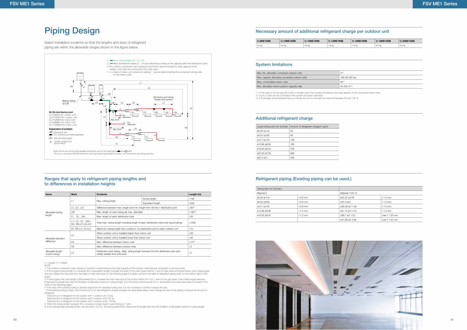
Select installation locations so that the lengths and sizes of refrigerant piping are within the allowable ranges shown in the figure below.
Explanation of symbolsDistribution joint (CZ-accessory, purchased separately)
Ball valve (field supply)
Solidly welded shut(pinch weld)
CZ-P680PJ2 (for outdoor unit)CZ-P1350PJ2 (for outdoor unit)CZ-P160BK2 (for indoor unit)CZ-P680BK2 (for indoor unit)CZ-P1350BK2 (for indoor unit)
R410A distribution joint
Note: Do not use commercially available distribution joint for the liquid tubing and parts.* Be sure to use special R410A distribution joints (purchased separately) for outdoor unit connections and tubing branches.
1.2. Main distribution tubes LC – LH are selected according to the capacity after the distribution joint.
4.
3.
Main tubing length LM = LA + LB …
Balance tubing
H3 C
B A
4
1 23
5 62 63 64
LO
LA
LF
LB LC
LG
LH
L4
LD L3
L1
L2
H1
H2
LM
(ø 6.35)
For extension
For extension
Max. 40 cm
Max. 40 cm
The outdoor connection main tubing (LO portion) is determined by the total capacity of the outdoor units that are connected to the tube ends.
Sizes of indoor unit connection tubing 1 – 64 are determined by the connection tubing sizes on the indoor units.
Distribution joint tubing (header joint system)
Items Mark Contents Length (m)
Allowable tubing length
L1 Max. tubing lengthActual length ≤180
Equivalent length ≤200
∆ L (L2 _L4) Difference between max. length and min. length from the No.1 distribution joint ≤50*5
LM Max. length of main tubing (at max. diameter) <180*3
ℓ1, ℓ2... ℓ64 Max. length of each distribution tube ≤30
L1+ ℓ1+ ℓ2... ℓ63+ℓA+ ℓB+LF+LG+LH Total max. tubing length including length of each distribution tube (only liquid tubing) ≤1000
ℓA, ℓB+LO, ℓC+LO Maximum tubing length from outdoor’s 1st distribution joint to each outdoor unit ≤10
Allowable elevation difference
H1When outdoor unit is installed higher than indoor unit ≤50
When outdoor unit is installed lower than indoor unit ≤40
H2 Max. difference between indoor units ≤15*6
H3 Max. difference between outdoor units ≤4
Allowable length of joint tubing L3 Distribution joint tubing ; Max. tubing length between the �rst distribution joint and
solidly welded-shut end point ≤2
L = Length, H = HeightNOTE1: The outdoor connection main tubing (LO portion) is determined by the total capacity of the outdoor units that are connected to the tube ends.2: If the longest tubing length (L1) exceeds 90 m (equivalent length), increase the sizes of the main tubes (LM) by 1 rank for gas tubes and liquid tubes. (Use a field supply reducer.) (Select the tube size from the table of main tube sizes on the following page (LA table), and from the table of refrigerant piping sizes on the bottom-right of this page.)3: If the longest main tube length (LM) exceeds 50 m, increase the main tube size at the portion before 50 m by 1 rank for the gas tubes. (Use a field supply reducer.) Determine the length less than the limitation of allowable maximum tubing length. (For the portion that exceeds 50 m, set based on the main tube sizes (LA) listed in the table on the following page.)4: If the size of the existing tubing is already larger than the standard tubing size, it is not necessary to further increase the size. * If the existing tubing is used, and the amount of on-site refrigerant charge exceeds the value listed below, then change the size of the tubing to reduce the amount of refrigerant. Total amount of refrigerant for the system with 1 outdoor unit: 50 kg Total amount of refrigerant for the system with 2 outdoor units: 80 kg Total amount of refrigerant for the system with 3 outdoor units: 100 kg5: When the tubing length exceeds 40m, increase a longer liquid or gas tubing by 1 rank.6: If the tubing length exceeds 500m, the formula is 15 x (2 - all tubing length/500). Determine the length less than the limitation of allowable maximum tubing length.
*1: In the case of 24 hp (type 68.0 kW) or smaller units, the number is limited by the total capacity of the connected indoor units.*2: Up to 3 units can be connected if the system has been extended.*3: It is strongly recommended that you choose the unit so the load can become between 50 and 130 %.
U-8ME1R8B U-10ME1R8B U-12ME1R8B U-14ME1R8B U-16ME1R8B U-18ME1R8B U-20ME1R8B
5.9 kg 6.6 kg 6.6 kg 7.8 kg 7.8 kg 8.5 kg 8.5 kg
Max. No. allowable connected outdoor units 3*2
Max. capacity allowable connected outdoor units 168 kW (60 hp)
Max. connectable indoor units 64*1
Max. allowable indoor/outdoor capacity ratio 50-200 %*3
Liquid tubing size mm (inches) Amount of refrigerant charge/m (g/m)
ø6.35 (ø1/4) 26
ø9.52 (ø3/8) 56
ø12.7 (ø1/2) 128
ø15.88 (ø5/8) 185
ø19.05 (ø3/4) 259
ø22.22 (ø7/8) 366
ø25.4 (ø1) 490
Tubing size mm (inches )
Material 0 Material 1/2H, H
ø6.35 (ø1/4) t 0.8 mm ø22.22 (ø7/8) t 1.0 mm
ø9.52 (ø3/8) t 0.8 mm ø25.4 (ø1) t 1.0 mm
ø12.7 (ø1/2) t 0.8 mm ø28.58 (ø1-1/8) t 1.0 mm
ø15.88 (ø5/8) t 1.0 mm ø31.75 (ø1-1/4) t 1.0 mm
ø19.05 (ø3/4) t 1.2 mm ø38.1 (ø1-1/2) over t 1.35 mm
ø41.28 (ø1-5/8) over t 1.45 mm
Piping Design
FSV ME1 Series
30 31
175135
11097
HIJ
C
D
EF
GH
114
72G
F F
H
G
GBA
CD
B
B
A
C D
175135
11097
HIJ
C
D
EF
GH
114
72G
F F
H
G
GBA
CD
B
B
A
C D
175135
110
97
E
E
FG
FGH
BCD
EF
EB C D F G HD C BE F 114
72A
A
A
110
97
110
97
7272BA DB
BC
C
C D E
A
CDE
C
110
97
110
97
7272BA DB
BC
C
C D E
A
CDE
C
B
D
DEF
FEDC
C
C
175
135
114 E F
F
H
F
I
HI
HI
G
G
G
110
97
72
Size of connection point on each part (Shown are inside diameters of tubing)
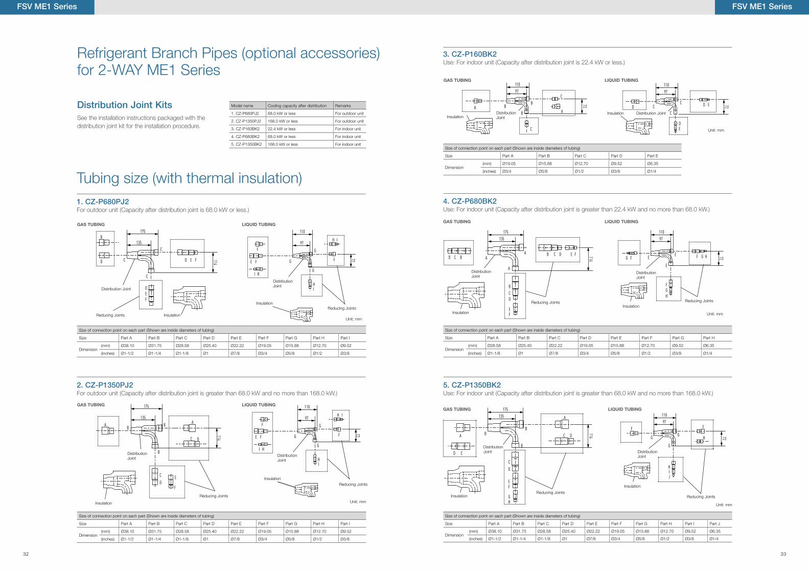
Size Part A Part B Part C Part D Part E
Dimension(mm) Ø19.05 Ø15.88 Ø12.70 Ø9.52 Ø6.35
(inches) Ø3/4 Ø5/8 Ø1/2 Ø3/8 Ø1/4
Refrigerant Branch Pipes (optional accessories) for 2-WAY ME1 Series
See the installation instructions packaged with the distribution joint kit for the installation procedure.
Distribution Joint Kits
Tubing size (with thermal insulation)
B
D
DEF
FEDC
C
C
175
135
114 E F
F
H
F
I
HI
HI
G
G
G
110
97
72A A
B
E F
F
H
F
I
HI
HI
G
G
GB
B
175
135
110
97
C
C
D
D
114
72
E
F
175135
110
97
E
E
FG
FGH
BCD
EF
EB C D F G HD C BE F 114
72A
A
A
Distribution Joint
Distribution Joint
Distribution Joint
Distribution Joint
Distribution Joint
Distribution Joint
Distribution Joint
Distribution Joint
Distribution Joint
Distribution Joint
Reducing Joints
Reducing Joints
Reducing Joints
Reducing Joints
Reducing Joints
Reducing Joints
Reducing Joints
Reducing Joints
Unit: mm
Unit: mm
Unit: mm
Unit: mm
Unit: mm
Insulation
Insulation
Insulation
Insulation
Insulation
Insulation
Insulation
Insulation
Insulation
Insulation
GAS TUBINGGAS TUBING
GAS TUBING
LIQUID TUBINGLIQUID TUBING
LIQUID TUBING
Size of connection point on each part (Shown are inside diameters of tubing)
Size Part A Part B Part C Part D Part E Part F Part G Part H Part I
Dimension (mm) Ø38.10 Ø31.75 Ø28.58 Ø25.40 Ø22.22 Ø19.05 Ø15.88 Ø12.70 Ø9.52
(inches) Ø1-1/2 Ø1-1/4 Ø1-1/8 Ø1 Ø7/8 Ø3/4 Ø5/8 Ø1/2 Ø3/8
Size of connection point on each part (Shown are inside diameters of tubing)
Size Part A Part B Part C Part D Part E Part F Part G Part H Part I
Dimension (mm) Ø38.10 Ø31.75 Ø28.58 Ø25.40 Ø22.22 Ø19.05 Ø15.88 Ø12.70 Ø9.52
(inches) Ø1-1/2 Ø1-1/4 Ø1-1/8 Ø1 Ø7/8 Ø3/4 Ø5/8 Ø1/2 Ø3/8
Size of connection point on each part (Shown are inside diameters of tubing)
Size Part A Part B Part C Part D Part E Part F Part G Part H
Dimension(mm) Ø28.58 Ø25.40 Ø22.22 Ø19.05 Ø15.88 Ø12.70 Ø9.52 Ø6.35
(inches) Ø1-1/8 Ø1 Ø7/8 Ø3/4 Ø5/8 Ø1/2 Ø3/8 Ø1/4
Size of connection point on each part (Shown are inside diameters of tubing)
Size Part A Part B Part C Part D Part E Part F Part G Part H Part I Part J
Dimension(mm) Ø38.10 Ø31.75 Ø28.58 Ø25.40 Ø22.22 Ø19.05 Ø15.88 Ø12.70 Ø9.52 Ø6.35
(inches) Ø1-1/2 Ø1-1/4 Ø1-1/8 Ø1 Ø7/8 Ø3/4 Ø5/8 Ø1/2 Ø3/8 Ø1/4
Use: For indoor unit (Capacity after distribution joint is greater than 68.0 kW and no more than 168.0 kW.)For outdoor unit (Capacity after distribution joint is greater than 68.0 kW and no more than 168.0 kW.)
For outdoor unit (Capacity after distribution joint is 68.0 kW or less.) Use: For indoor unit (Capacity after distribution joint is greater than 22.4 kW and no more than 68.0 kW.)
Use: For indoor unit (Capacity after distribution joint is 22.4 kW or less.)
5. CZ-P1350BK22. CZ-P1350PJ2
1. CZ-P680PJ2 4. CZ-P680BK2
3. CZ-P160BK2
A AB
E F
F
H
F
I
HI
HI
G
G
GB
B
175
135
110
97
C
C
D
D
114
72
E
F
Model name Cooling capacity after distribution Remarks
1. CZ-P680PJ2 68.0 kW or less For outdoor unit
2. CZ-P1350PJ2 168.0 kW or less For outdoor unit
3. CZ-P160BK2 22.4 kW or less For indoor unit
4. CZ-P680BK2 68.0 kW or less For indoor unit
5. CZ-P1350BK2 168.0 kW or less For indoor unit
FSV ME1 Series
GAS TUBINGGAS TUBING
LIQUID TUBINGLIQUID TUBING
FSV ME1 Series
32 33
FSV MF2 Series
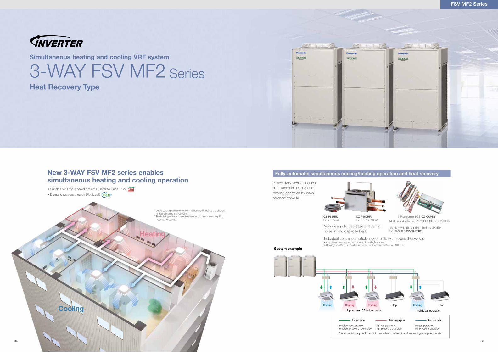
Series3-WAY FSV MF2Simultaneous heating and cooling VRF system
New 3-WAY FSV MF2 series enables simultaneous heating and cooling operation
Heat Recovery Type
Heating
Cooling
3-WAY MF2 series enables simultaneous heating and cooling operation by each solenoid valve kit.
CZ-P56HR3Up to 5.6 kW
CZ-P160HR3 From 5.7 to 16 kW
3-Pipe control PCB CZ-CAPE2*
Fully-automatic simultaneous cooling/heating operation and heat recovery
System example
Up to max. 52 indoor unitsCooling Cooling StopStop
Individual operationHeating Heating
Liquid pipe Discharge pipe Suction pipelow-temperature, low-pressure gas pipe
high-temperature, high-pressure gas pipe
medium-temperature, medium-pressure liquid pipe
* When individually controlled with one solenoid valve kit, address setting is required on site.
New design to decrease chattering noise at low capacity load.
Must be added to the CZ-P56HR3 OR CZ-P160HR3.
*For S-45MK1E5/S-56MK1E5/S-73MK1E5/S-106MK1E5:CZ-CAPEK2.
Individual control of multiple indoor units with solenoid valve kits• Any design and layout can be used in a single system.• Cooling operation is possible up to an outdoor temperature of -10˚C DB.
• Suitable for R22 renewal projects (Refer to Page 112)
• Demand response ready (Peak cut)
* Of�ce building with diverse room temperatures due to the different amount of sunshine received.
* The building with computer/business equipment rooms requiring year-round cooling.
34 35
Simultaneous heating and cooling VRF system
3-WAY FSV MF2 Series
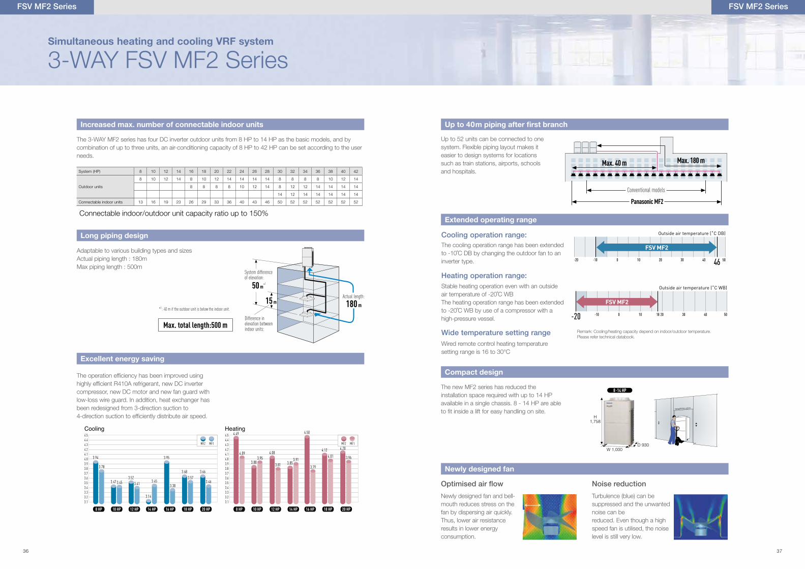
The 3-WAY MF2 series has four DC inverter outdoor units from 8 HP to 14 HP as the basic models, and by combination of up to three units, an air-conditioning capacity of 8 HP to 42 HP can be set according to the user needs.
The operation ef�ciency has been improved using highly ef�cient R410A refrigerant, new DC inverter compressor, new DC motor and new fan guard with low-loss wire guard. In addition, heat exchanger has been redesigned from 3-direction suction to 4-direction suction to ef�ciently distribute air speed.
Adaptable to various building types and sizesActual piping length : 180mMax piping length : 500m
Increased max. number of connectable indoor units
Long piping design
Excellent energy saving
Actual length:
180 m15 m
50 m *1
Difference in elevation between indoor units:
*1: 40 m if the outdoor unit is below the indoor unit.
System difference of elevation:
Max. total length:500 m
4.54.44.34.24.14.03.93.83.73.63.53.43.33.23.1
4.54.44.34.24.14.03.93.83.73.63.53.43.33.23.1
Heating
10 HP8 HP
4.49
4.09
3.883.95
4.08
3.81 3.853.91
12 HP
NEW 3-WAY MF2 SERIES
14 HP 18 HP16 HP
4.50
3.79
4.124.01 3.96
20 HP
OLD SERIES
MF2 MF14.20
10 HP8 HP 12 HP
Cooling
14 HP 18 HP16 HP 20 HP
MF2 MF1
3.94
3.78
3.47 3.453.52
3.41
3.14
3.45
3.95
3.38
3.683.57
3.66
3.46
3.94
3.78
3.47 3.453.52
3.41
3.14
3.45
3.95
3.38
3.683.57
3.66
3.46
System (HP) 8 10 12 14 16 18 20 22 24 26 28 30 32 34 36 38 40 42
Outdoor units
8 10 12 14 8 10 12 14 14 14 14 8 8 8 8 10 12 14
8 8 8 8 10 12 14 8 12 12 14 14 14 14
14 12 14 14 14 14 14
Connectable indoor units 13 16 19 23 26 29 33 36 40 43 46 50 52 52 52 52 52 52
FSV MF2 Series
Up to 52 units can be connected to one system. Flexible piping layout makes it easier to design systems for locations such as train stations, airports, schools and hospitals.
Conventional models
Panasonic MF2
Max. 180 mMax. 40 m
Up to 40m piping after first branch
The cooling operation range has been extended to -10˚C DB by changing the outdoor fan to an inverter type.
Cooling operation range:
Stable heating operation even with an outside air temperature of -20˚C WBThe heating operation range has been extended to -20˚C WB by use of a compressor with a high-pressure vessel.
Heating operation range:
Wired remote control heating temperature setting range is 16 to 30°C
Wide temperature setting range
Extended operating range
Outside air temperature (˚C DB)
-20 -10 0 10 20 30 40 46 50
FSV MF2
Outside air temperature (˚C WB)
-20 -10 0 10 20 30 4018 50
FSV MF2
Noise reduction
H1,758
W 1,000D 930
8 -14 HPThe new MF2 series has reduced the installation space required with up to 14 HP available in a single chassis. 8 - 14 HP are able to �t inside a lift for easy handling on site.
Newly designed fan and bell-mouth reduces stress on the fan by dispersing air quickly. Thus, lower air resistance results in lower energy consumption.
Turbulence (blue) can be suppressed and the unwanted noise can bereduced. Even though a high speed fan is utilised, the noise level is still very low.
Compact design
Newly designed fan
Connectable indoor/outdoor unit capacity ratio up to 150%
Remark: Cooling/heating capacity depend on indoor/outdoor temperature.Please refer technical databook.
FSV MF2 Series
36 37
Simultaneous heating and cooling VRF system
3-WAY FSV MF2 Series
FSV MF2 Series
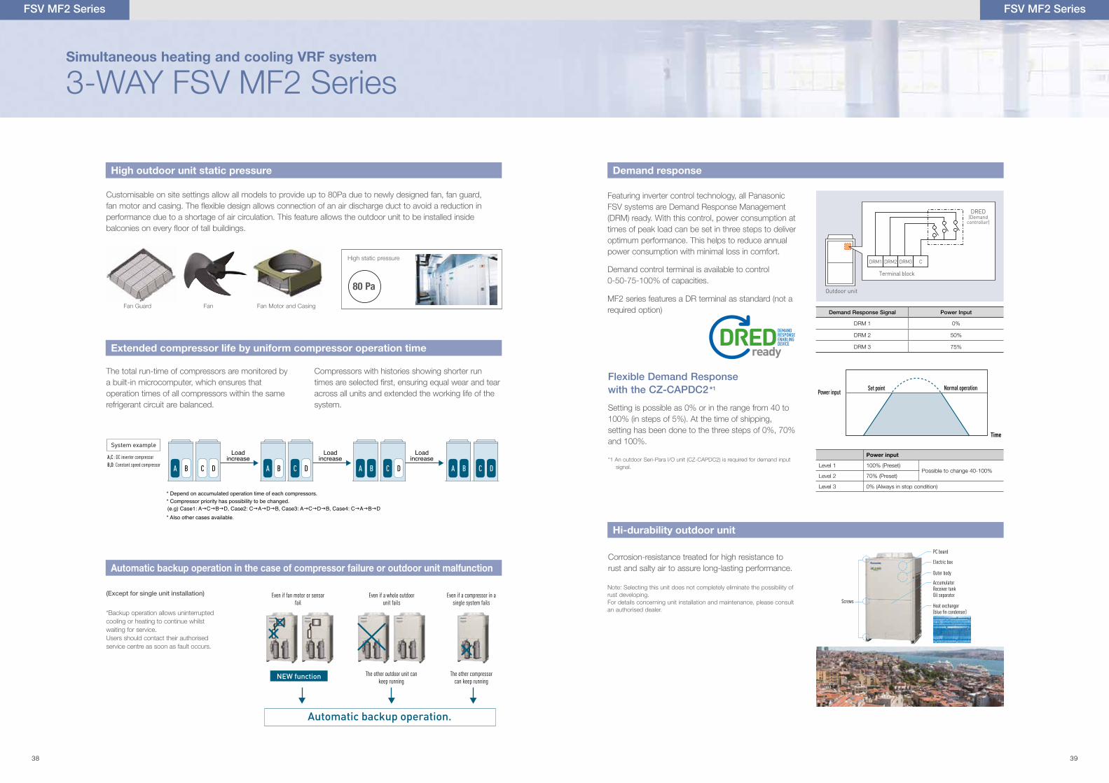
Customisable on site settings allow all models to provide up to 80Pa due to newly designed fan, fan guard,fan motor and casing. The �exible design allows connection of an air discharge duct to avoid a reduction inperformance due to a shortage of air circulation. This feature allows the outdoor unit to be installed insidebalconies on every �oor of tall buildings.
*Backup operation allows uninterrupted cooling or heating to continue whilst waiting for service.Users should contact their authorised service centre as soon as fault occurs.
The total run-time of compressors are monitored by a built-in microcomputer, which ensures that operation times of all compressors within the same refrigerant circuit are balanced.
Compressors with histories showing shorter run times are selected �rst, ensuring equal wear and tear across all units and extended the working life of the system.
Fan Guard Fan Fan Motor and Casing
High static pressure
High outdoor unit static pressure
Automatic backup operation in the case of compressor failure or outdoor unit malfunction
Extended compressor life by uniform compressor operation time
80 Pa
A,C : DC inverter compressor
B,D: Constant speed compressor
System example
A B C D A B C D A B C D A B C D
Loadincrease
Loadincrease
Loadincrease
* Also other cases available.
* Depend on accumulated operation time of each compressors.* Compressor priority has possibility to be changed.(e.g) Case1: AgCgBgD, Case2: CgAgDgB, Case3: AgCgDgB, Case4: CgAgBgD
(Except for single unit installation) Even if fan motor or sensorfail
Even if a compressor in asingle system fails
Even if a whole outdoorunit fails
The other compressor can keep running
The other outdoor unit can keep running
Automatic backup operation.
NEW function
Setting is possible as 0% or in the range from 40 to 100% (in steps of 5%). At the time of shipping, setting has been done to the three steps of 0%, 70% and 100%.
Flexible Demand Response with the CZ-CAPDC2*1
*1 An outdoor Seri-Para l/O unit (CZ-CAPDC2) is required for demand input signal.
Power input
Level 1 100% (Preset)Possible to change 40-100%
Level 2 70% (Preset)
Level 3 0% (Always in stop condition)
Set point
Time
Normal operationPower input
Demand response
Featuring inverter control technology, all Panasonic FSV systems are Demand Response Management (DRM) ready. With this control, power consumption at times of peak load can be set in three steps to deliver optimum performance. This helps to reduce annual power consumption with minimal loss in comfort.
Outdoor unit
CDRM1 DRM2 DRM3
Terminal block
Current input is DC 24 V 10 mA
DRED (Demand
controller)Relay contact
point:No voltage relay
Demand Response Signal Power Input
DRM 1 0%
DRM 2 50%
DRM 3 75%
FSV MF2 Series
Hi-durability outdoor unit
Corrosion-resistance treated for high resistance to rust and salty air to assure long-lasting performance.
Note: Selecting this unit does not completely eliminate the possibility of rust developing. For details concerning unit installation and maintenance, please consult an authorised dealer.
Screws
PC board
Electric box
Outer body
AccumulatorReceiver tankOil separator
Heat exchanger (blue fin condenser)
Demand control terminal is available to control 0-50-75-100% of capacities.
MF2 series features a DR terminal as standard (not a required option)
38 39
3-WAY FSV MF2 Series
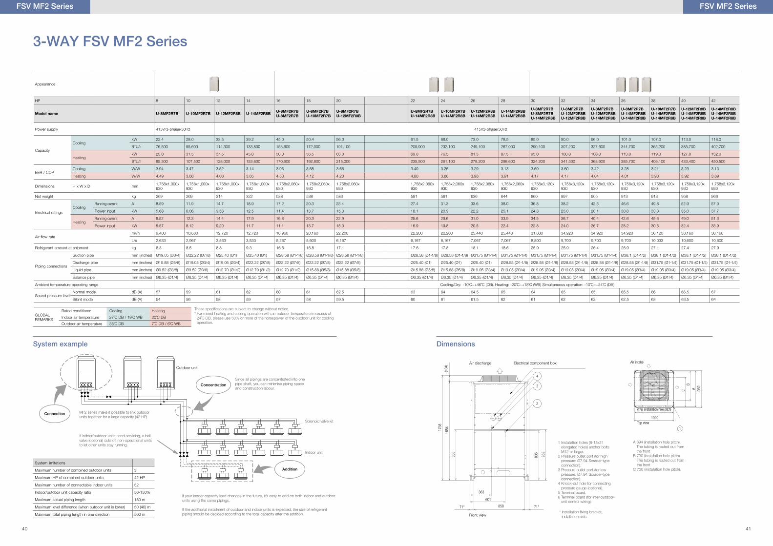
Appearance
HP 8 10 12 14 16 18 20 22 24 26 28 30 32 34 36 38 40 42
Model name U-8MF2R7B U-10MF2R7B U-12MF2R8B U-14MF2R8B U-8MF2R7BU-8MF2R7B
U-8MF2R7BU-10MF2R7B
U-8MF2R7BU-12MF2R8B
U-8MF2R7BU-14MF2R8B
U-10MF2R7BU-14MF2R8B
U-12MF2R8BU-14MF2R8B
U-14MF2R8BU-14MF2R8B
U-8MF2R7BU-8MF2R7BU-14MF2R8B
U-8MF2R7BU-12MF2R8BU-12MF2R8B
U-8MF2R7BU-12MF2R8BU-14MF2R8B
U-8MF2R7BU-14MF2R8BU-14MF2R8B
U-10MF2R7BU-14MF2R8BU-14MF2R8B
U-12MF2R8BU-14MF2R8BU-14MF2R8B
U-14MF2R8BU-14MF2R8BU-14MF2R8B
Power supply 415V/3-phase/50Hz 415V3-phase/50Hz
Capacity
CoolingkW 22.4 28.0 33.5 39.2 45.0 50.4 56.0 61.5 68.0 73.0 78.5 85.0 90.0 96.0 101.0 107.0 113.0 118.0
BTU/h 76,500 95,600 114,300 133,800 153,600 172,000 191,100 209,900 232,100 249,100 267,900 290,100 307,200 327,600 344,700 365,200 385,700 402,700
HeatingkW 25.0 31.5 37.5 45.0 50.0 56.5 63.0 69.0 76.5 81.5 87.5 95.0 100.0 108.0 113.0 119.0 127.0 132.0
BTU/h 85,300 107,500 128,000 153,600 170,600 192,800 215,000 235,500 261,100 278,200 298,600 324,200 341,300 368,600 385,700 406,100 433,400 450,500
EER / COPCooling W/W 3.94 3.47 3.52 3.14 3.95 3.68 3.66 3.40 3.25 3.29 3.13 3.50 3.60 3.42 3.28 3.21 3.23 3.13
Heating W/W 4.49 3.88 4.08 3.85 4.50 4.12 4.20 4.80 3.86 3.98 3.91 4.17 4.17 4.04 4.01 3.90 3.92 3.89
Dimensions H x W x D mm 1,758x1,000x930
1,758x1,000x930
1,758x1,000x930
1,758x1,000x930
1,758x2,060x930
1,758x2,060x930
1,758x2,060x930
1,758x2,060x930
1,758x2,060x930
1,758x2,060x930
1,758x2,060x930
1,758x3,120x930
1,758x3,120x930
1,758x3,120x930
1,758x3,120x930
1,758x3,120x930
1,758x3,120x930
1,758x3,120x930
Net weight kg 269 269 314 322 538 538 583 591 591 636 644 860 897 905 913 913 958 966
Electrical ratingsCooling
Running current A 8.59 11.9 14.7 18.9 17.2 20.3 23.4 27.4 31.3 33.6 38.0 36.8 38.2 42.5 46.6 49.8 52.9 57.0
Power input kW 5.68 8.06 9.53 12.5 11.4 13.7 15.3 18.1 20.9 22.2 25.1 24.3 25.0 28.1 30.8 33.3 35.0 37.7
HeatingRunning current A 8.52 12.3 14.4 17.9 16.8 20.3 22.9 25.6 29.6 31.0 33.9 34.5 36.7 40.4 42.6 45.6 49.0 51.3
Power input kW 5.57 8.12 9.20 11.7 11.1 13.7 15.0 16.9 19.8 20.5 22.4 22.8 24.0 26.7 28.2 30.5 32.4 33.9
Air �ow ratem³/h 9,480 10,680 12,720 12,720 18,960 20,160 22,200 22,200 22,200 25,440 25,440 31,680 34,920 34,920 34,920 36,120 38,160 38,160
L/s 2,633 2,967 3,533 3,533 5,267 5,600 6,167 6,167 6,167 7,067 7,067 8,800 9,700 9,700 9,700 10.033 10,600 10,600
Refrigerant amount at shipment kg 8.3 8.5 8.8 9.3 16.6 16.8 17.1 17.6 17.8 18.1 18.6 25.9 25.9 26.4 26.9 27.1 27.4 27.9
Piping connections
Suction pipe mm (inches) Ø19.05 (Ø3/4) Ø22.22 (Ø7/8) Ø25.40 (Ø1) Ø25.40 (Ø1) Ø28.58 (Ø1-1/8) Ø28.58 (Ø1-1/8) Ø28.58 (Ø1-1/8) Ø28.58 (Ø1-1/8) Ø28.58 (Ø1-1/8) Ø31.75 (Ø1-1/4) Ø31.75 (Ø1-1/4) Ø31.75 (Ø1-1/4) Ø31.75 (Ø1-1/4) Ø31.75 (Ø1-1/4) Ø38.1 (Ø1-1/2) Ø38.1 (Ø1-1/2) Ø38.1 (Ø1-1/2) Ø38.1 (Ø1-1/2)
Discharge pipe mm (inches) Ø15.88 (Ø5/8) Ø19.05 (Ø3/4) Ø19.05 (Ø3/4) Ø22.22 (Ø7/8) Ø22.22 (Ø7/8) Ø22.22 (Ø7/8) Ø22.22 (Ø7/8) Ø25.40 (Ø1) Ø25.40 (Ø1) Ø25.40 (Ø1) Ø28.58 (Ø1-1/8) Ø28.58 (Ø1-1/8) Ø28.58 (Ø1-1/8) Ø28.58 (Ø1-1/8) Ø28.58 (Ø1-1/8) Ø31.75 (Ø1-1/4) Ø31.75 (Ø1-1/4) Ø31.75 (Ø1-1/4)
Liquid pipe mm (inches) Ø9.52 (Ø3/8) Ø9.52 (Ø3/8) Ø12.70 (Ø1/2) Ø12.70 (Ø1/2) Ø12.70 (Ø1/2) Ø15.88 (Ø5/8) Ø15.88 (Ø5/8) Ø15.88 (Ø5/8) Ø15.88 (Ø5/8) Ø19.05 (Ø3/4) Ø19.05 (Ø3/4) Ø19.05 (Ø3/4) Ø19.05 (Ø3/4) Ø19.05 (Ø3/4) Ø19.05 (Ø3/4) Ø19.05 (Ø3/4) Ø19.05 (Ø3/4) Ø19.05 (Ø3/4)
Balance pipe mm (inches) Ø6.35 (Ø1/4) Ø6.35 (Ø1/4) Ø6.35 (Ø1/4) Ø6.35 (Ø1/4) Ø6.35 (Ø1/4) Ø6.35 (Ø1/4) Ø6.35 (Ø1/4) Ø6.35 (Ø1/4) Ø6.35 (Ø1/4) Ø6.35 (Ø1/4) Ø6.35 (Ø1/4) Ø6.35 (Ø1/4) Ø6.35 (Ø1/4) Ø6.35 (Ø1/4) Ø6.35 (Ø1/4) Ø6.35 (Ø1/4) Ø6.35 (Ø1/4) Ø6.35 (Ø1/4)
Ambient temperature operating range Cooling/Dry: -10˚C~+46˚C (DB). Heating: -20˚C~+18˚C (WB) Simultaneous operation: -10˚C~+24˚C (DB)
Sound pressure levelNormal mode dB (A) 57 59 61 62 60 61 62.5 63 64 64.5 65 64 65 65 65.5 66 66.5 67
Silent mode dB (A) 54 56 58 59 57 58 59.5 60 61 61.5 62 61 62 62 62.5 63 63.5 64
System example Dimensions
Outdoor unit
Solenoid valve kit
Indoor unit
MF2 series make it possible to link outdoor units together for a large capacity (42 HP)
If indoor/outdoor units need servicing, a ball valve (optional) cuts off non-operational units to let other units stay running.
If your indoor capacity load changes in the future, it’s easy to add on both indoor and outdoor units using the same pipings.
If the additional installment of outdoor and indoor units is expected, the size of refrigerant piping should be decided according to the total capacity after the addition.
Since all pipings are concentrated into one pipe shaft, you can minimise piping space and construction labour.
Connection
Concentration
Addition
System limitations
Maximum number of combined outdoor units 3
Maximum HP of combined outdoor units 42 HP
Maximum number of connectable indoor units 52
Indoor/outdoor unit capacity ratio 50-150%
Maximum actual piping length 180 m
Maximum level difference (when outdoor unit is lower) 50 (40) m
Maximum total piping length in one direction 500 m
These speci�cations are subject to change without notice.* For mixed heating and cooling operation with an outdoor temperature in excess of
24˚C DB, please use 50% or more of the horsepower of the outdoor unit for cooling operation.
FSV MF2 Series
GLOBAL REMARKS
Rated conditions: Cooling Heating
Indoor air temperature 27˚C DB / 19˚C WB 20˚C DB
Outdoor air temperature 35˚C DB 7˚C DB / 6˚C WB
Front view* Installation �xing bracket,
installation side.
Electrical component box
1 Installation holes (8-15x21 elongated holes) anchor bolts M12 or larger.
2 Pressure outlet port (for high pressure: Ø7.94 Scrader-type connection).
3 Pressure outlet port (for low pressure: Ø7.94 Scrader-type connection).
4 Knock-out hole for connecting pressure gauge (optional).
5 Terminal board.6 Terminal board (for inter-outdoor-
unit control wiring).
Air discharge
4
3
2
1
4
3
2
Top view
(installation hole pitch)
A 894 (installation hole pitch). The tubing is routed out from the front
B 730 (installation hole pitch). The tubing is routed out from the front
C 730 (installation hole pitch).
Air intake
FSV MF2 Series
40 41
FSV MF2 Series
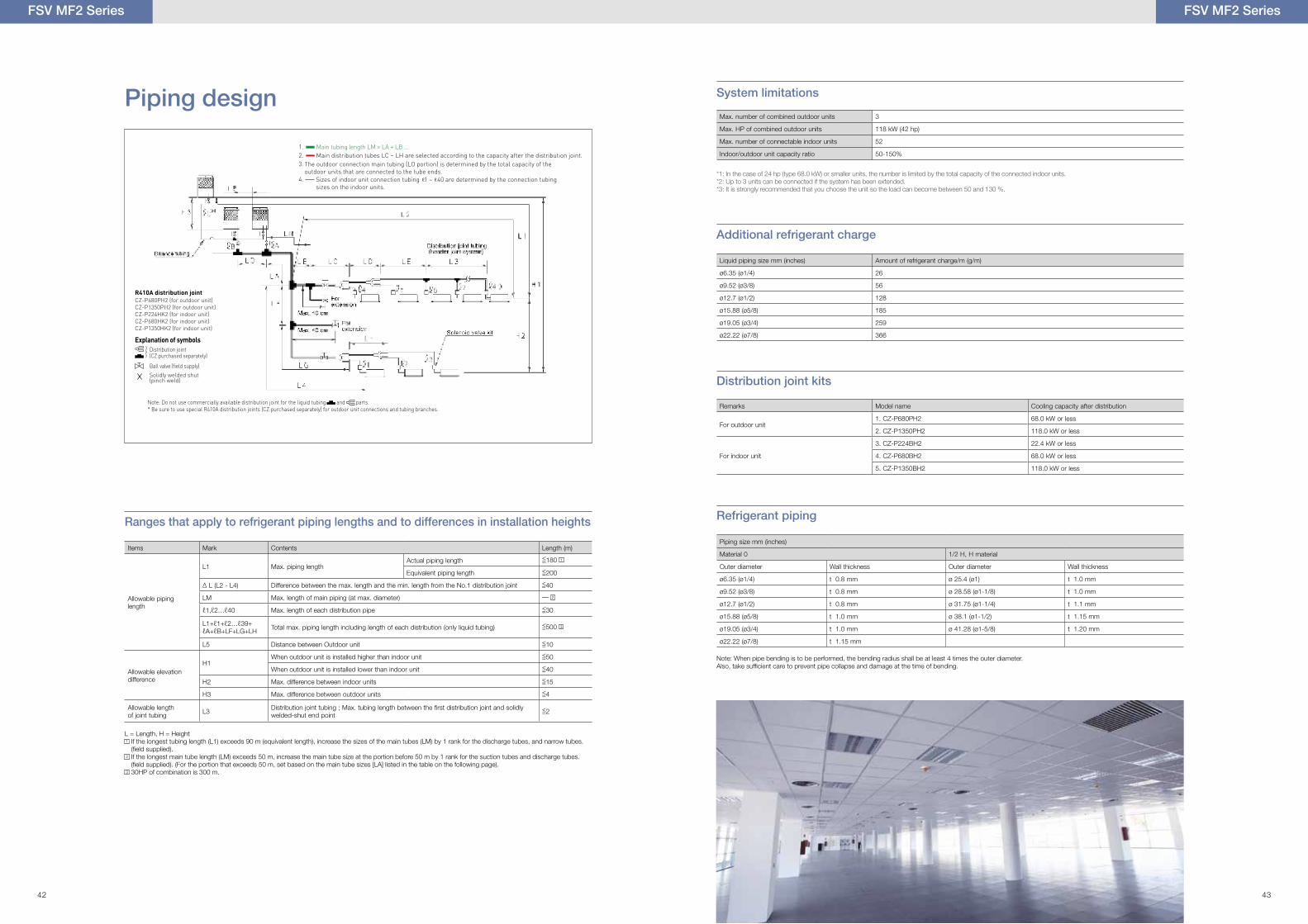
Piping design System limitations
Additional refrigerant charge
Refrigerant piping
Distribution joint kits
Max. number of combined outdoor units 3
Max. HP of combined outdoor units 118 kW (42 hp)
Max. number of connectable indoor units 52
Indoor/outdoor unit capacity ratio 50-150%
Liquid piping size mm (inches) Amount of refrigerant charge/m (g/m)
ø6.35 (ø1/4) 26
ø9.52 (ø3/8) 56
ø12.7 (ø1/2) 128
ø15.88 (ø5/8) 185
ø19.05 (ø3/4) 259
ø22.22 (ø7/8) 366
Piping size mm (inches)
Material 0 1/2 H, H material
Outer diameter Wall thickness Outer diameter Wall thickness
ø6.35 (ø1/4) t 0.8 mm ø 25.4 (ø1) t 1.0 mm
ø9.52 (ø3/8) t 0.8 mm ø 28.58 (ø1-1/8) t 1.0 mm
ø12.7 (ø1/2) t 0.8 mm ø 31.75 (ø1-1/4) t 1.1 mm
ø15.88 (ø5/8) t 1.0 mm ø 38.1 (ø1-1/2) t 1.15 mm
ø19.05 (ø3/4) t 1.0 mm ø 41.28 (ø1-5/8) t 1.20 mm
ø22.22 (ø7/8) t 1.15 mm
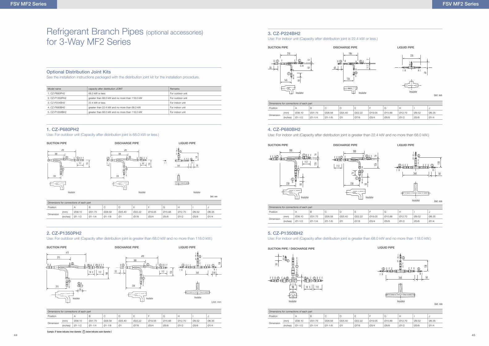
Remarks Model name Cooling capacity after distribution
For outdoor unit1. CZ-P680PH2 68.0 kW or less
2. CZ-P1350PH2 118.0 kW or less
For indoor unit
3. CZ-P224BH2 22.4 kW or less
4. CZ-P680BH2 68.0 kW or less
5. CZ-P1350BH2 118.0 kW or less
Note: When pipe bending is to be performed, the bending radius shall be at least 4 times the outer diameter. Also, take sufficient care to prevent pipe collapse and damage at the time of bending.
Ranges that apply to refrigerant piping lengths and to differences in installation heights
L = Length, H = Height1 If the longest tubing length (L1) exceeds 90 m (equivalent length), increase the sizes of the main tubes (LM) by 1 rank for the discharge tubes, and narrow tubes.
(field supplied).2 If the longest main tube length (LM) exceeds 50 m, increase the main tube size at the portion before 50 m by 1 rank for the suction tubes and discharge tubes.
(field supplied). (For the portion that exceeds 50 m, set based on the main tube sizes [LA] listed in the table on the following page).3 30HP of combination is 300 m.
Items Mark Contents Length (m)
Allowable piping length
L1 Max. piping lengthActual piping length <=180 1
Equivalent piping length <=200
∆ L (L2 - L4) Difference between the max. length and the min. length from the No.1 distribution joint <=40
LM Max. length of main piping (at max. diameter) –– 2
ℓ1,ℓ2…ℓ40 Max. length of each distribution pipe <=30
L1+ℓ1+ℓ2…ℓ39+ℓA+ℓB+LF+LG+LH Total max. piping length including length of each distribution (only liquid tubing) <=500 3
L5 Distance between Outdoor unit <=10
Allowable elevation difference
H1When outdoor unit is installed higher than indoor unit <=50
When outdoor unit is installed lower than indoor unit <=40
H2 Max. difference between indoor units <=15
H3 Max. difference between outdoor units <=4
Allowable length of joint tubing L3 Distribution joint tubing ; Max. tubing length between the �rst distribution joint and solidly
welded-shut end point<=2
Sizes of indoor unit connection tubing 1 – 40 are determined by the connection tubing sizes on the indoor units.
Explanation of symbolsDistribution joint (CZ:purchased separately)
Ball valve (field supply)
Solidly welded shut(pinch weld)
CZ-P680PH2 (for outdoor unit)CZ-P1350PH2 (for outdoor unit)CZ-P224HK2 (for indoor unit)CZ-P680HK2 (for indoor unit)CZ-P1350HK2 (for indoor unit)
R410A distribution joint
Note: Do not use commercially available distribution joint for the liquid tubing and parts.* Be sure to use special R410A distribution joints (CZ:purchased separately) for outdoor unit connections and tubing branches.
1.2. Main distribution tubes LC – LH are selected according to the capacity after the distribution joint.
4.
3.
Main tubing length LM = LA + LB …
Balance tubing
Solenoid valve kit
H3
B A
4
1 23
5 62 63 40
LO
LA
LF
LB LC
LG
LH
L4
LD L3
L1
L2
H1
H2
LM
For extension
For extension
Max. 40 cm
Max. 40 cm
The outdoor connection main tubing (LO portion) is determined by the total capacity of the outdoor units that are connected to the tube ends.
FSV MF2 Series
*1: In the case of 24 hp (type 68.0 kW) or smaller units, the number is limited by the total capacity of the connected indoor units.*2: Up to 3 units can be connected if the system has been extended.*3: It is strongly recommended that you choose the unit so the load can become between 50 and 130 %.
42 43
C
C
DEF
230
300
D E FC CF E D C
C
GF
112
126
55
16
G F E
I
I
H IH
H
G GG
G
F
F
EE
G
340 50
130
C
D
EFGH230
300
E FD DF E D C
D
F
112 126
55
16
74
C
C
DEF
230
300
D E FC CF E D C
C
GF
112
126
55
16
G F E
I
I
H IH
H
G GG
G
F
F
EE
G
340 50
130
C
D
EFGH230
300
E FD DF E D C
D
F
112 126
55
16
74
C C
C
DEF230
300
490
D E FCC C
C
112 126
C D
D
EFG230
300
490
E F GDD D G F E
I
I
IHH
H
GG G
G
F
F
EE
G
E D C
D
101340 50
83 126
130
C C
C
DEF230
300
490
D E FCC C
C
112 126
C D
D
EFG230
300
490
E F GDD D G F E
I
I
IHH
H
GG G
G
F
F
EE
G
E D C
D
101340 50
83 126
130
C C
C
DEF230
300
490
D E FCC C
C
112 126
C D
D
EFG230
300
490
E F GDD D G F E
I
I
IHH
H
GG G
G
F
F
EE
G
E D C
D
101340 50
83 126
130
Refrigerant Branch Pipes (optional accessories)
for 3-Way MF2 Series
Optional Distribution Joint KitsSee the installation instructions packaged with the distribution joint kit for the installation procedure.
B A B
B
CD
A315
375
615
A CBB
B D E FC
BB
66
10 5 112
180
G F E
I
I
H IH
H
G GG
G
F
F
EE
G
340 50
130
230
112 126
C
D
D
E
E
F
F
C
C CC CD CC
300
490
53
235
I
I
H IH
H
69
G
G
H145
210
G H
F
F F F
F
F
92
55
12
55
G
G
136
186
H
H H GH
H
H
77
7
40
HG
B B
BF E D C D E FCC A B CAB
DEF
C
AC
B
F
90 45
55
G F E
I
I
H IH
H
G GG
G
F
F
EE
G
340 50
130
10 5 112
Unit: mm
Unit: mm
Unit: mm
Insulator
Insulator
InsulatorInsulator
Insulator
Insulator
Insulator
Insulator
SUCTION PIPE
SUCTION PIPE
SUCTION PIPE
SUCTION PIPE
C
C
DEF
230
300
D E FC CF E D C
C
GF
112
126
55
16
G F E
I
I
H IH
H
G GG
G
F
F
EE
G
340 50
130
C
D
EFGH230
300
E FD DF E D C
D
F
112 126
55
16
74
Insulator
SUCTION PIPE / DISCHARGE PIPE
Insulator
DISCHARGE PIPE
DISCHARGE PIPE
DISCHARGE PIPE
DISCHARGE PIPE
LIQUID PIPE
LIQUID PIPE
LIQUID PIPE
LIQUID PIPE
LIQUID PIPE
Dimensions for connections of each part
Position A B C D E F G H I J
Dimension(mm) Ø38.10 Ø31.75 Ø28.58 Ø25.40 Ø22.22 Ø19.05 Ø15.88 Ø12.70 Ø9.52 Ø6.35
(inches) Ø1-1/2 Ø1-1/4 Ø1-1/8 Ø1 Ø7/8 Ø3/4 Ø5/8 Ø1/2 Ø3/8 Ø1/4
Dimensions for connections of each part
Position A B C D E F G H I J
Dimension(mm) Ø38.10 Ø31.75 Ø28.58 Ø25.40 Ø22.22 Ø19.05 Ø15.88 Ø12.70 Ø9.52 Ø6.35
(inches) Ø1-1/2 Ø1-1/4 Ø1-1/8 Ø1 Ø7/8 Ø3/4 Ø5/8 Ø1/2 Ø3/8 Ø1/4
Dimensions for connections of each part
Position A B C D E F G H I J
Dimension(mm) Ø38.10 Ø31.75 Ø28.58 Ø25.40 Ø22.22 Ø19.05 Ø15.88 Ø12.70 Ø9.52 Ø6.35
(inches) Ø1-1/2 Ø1-1/4 Ø1-1/8 Ø1 Ø7/8 Ø3/4 Ø5/8 Ø1/2 Ø3/8 Ø1/4
Dimensions for connections of each part
Position A B C D E F G H I J
Dimension(mm) Ø38.10 Ø31.75 Ø28.58 Ø25.40 Ø22.22 Ø19.05 Ø15.88 Ø12.70 Ø9.52 Ø6.35
(inches) Ø1-1/2 Ø1-1/4 Ø1-1/8 Ø1 Ø7/8 Ø3/4 Ø5/8 Ø1/2 Ø3/8 Ø1/4
Dimensions for connections of each part
Position A B C D E F G H I J
Dimension(mm) Ø38.10 Ø31.75 Ø28.58 Ø25.40 Ø22.22 Ø19.05 Ø15.88 Ø12.70 Ø9.52 Ø6.35
(inches) Ø1-1/2 Ø1-1/4 Ø1-1/8 Ø1 Ø7/8 Ø3/4 Ø5/8 Ø1/2 Ø3/8 Ø1/4
2. CZ-P1350PH2Use: For outdoor unit (Capacity after distribution joint is greater than 68.0 kW and no more than 118.0 kW.)
1. CZ-P680PH2Use: For outdoor unit (Capacity after distribution joint is 68.0 kW or less.)
3. CZ-P224BH2Use: For indoor unit (Capacity after distribution joint is 22.4 kW or less.)
4. CZ-P680BH2Use: For indoor unit (Capacity after distribution joint is greater than 22.4 kW and no more than 68.0 kW.)
5. CZ-P1350BH2Use: For indoor unit (Capacity after distribution joint is greater than 68.0 kW and no more than 118.0 kW.)
Example: (F below indicates inner diameter. F below indicates outer diameter.)
Model name capacity after distribution JOINT Remarks
1. CZ-P680PH2 68.0 kW or less For outdoor unit
2. CZ-P1350PH2 greater than 68.0 kW and no more than 118.0 kW For outdoor unit
3. CZ-P224BH2 22.4 kW or less For indoor unit
4. CZ-P680BH2 greater than 22.4 kW and no more than 68.0 kW For indoor unit
5. CZ-P1350BH2 greater than 68.0 kW and no more than 118.0 kW For indoor unit
Insulator
Unit: mm
Insulator
FSV MF2 Series
InsulatorUnit: mmInsulator
FSV MF2 Series
44 45
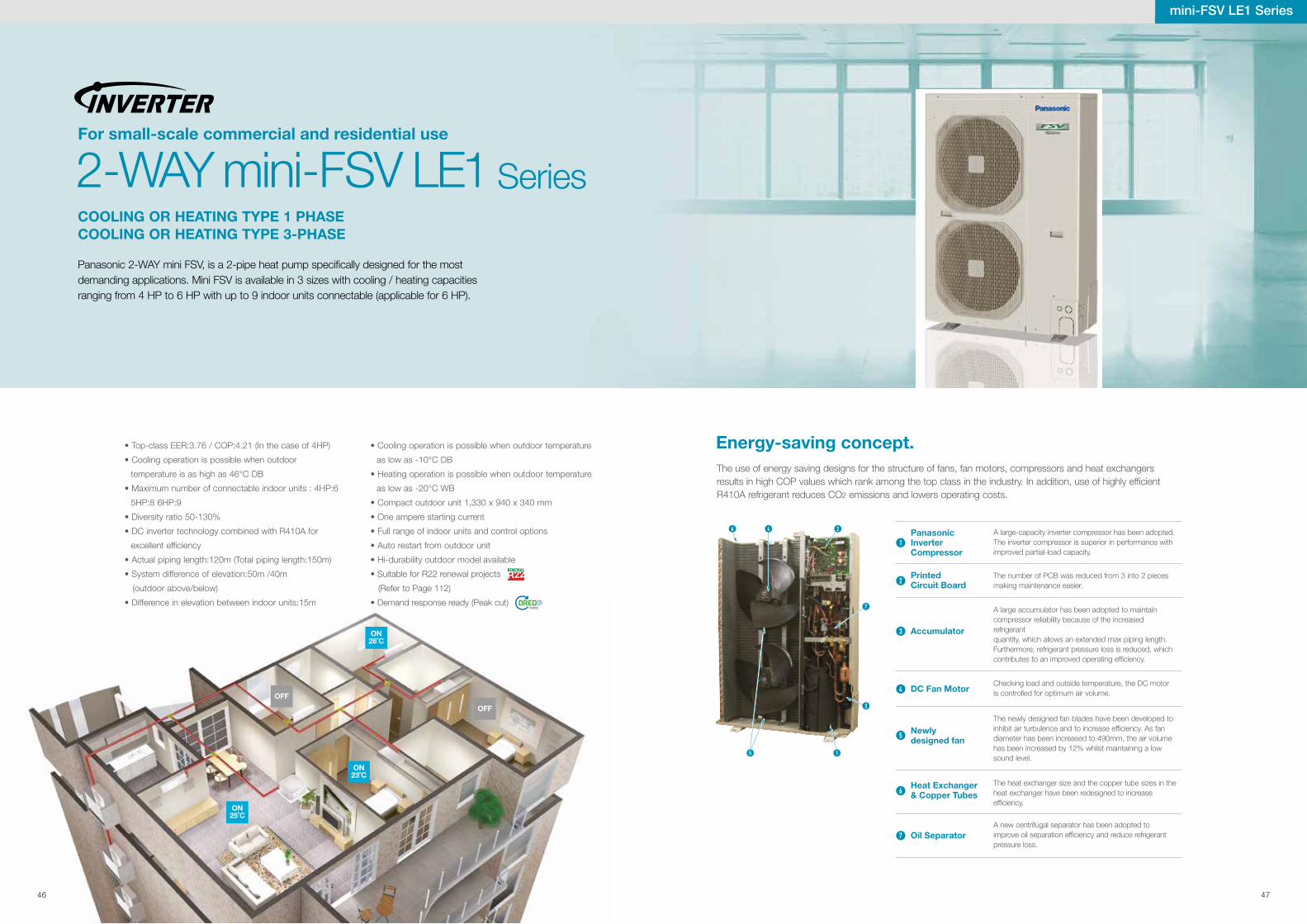
For small-scale commercial and residential use
COOLING OR HEATING TYPE 1 PHASECOOLING OR HEATING TYPE 3-PHASE
2-WAY mini-FSV LE1 Series
Panasonic 2-WAY mini FSV, is a 2-pipe heat pump speci�cally designed for the most demanding applications. Mini FSV is available in 3 sizes with cooling / heating capacities ranging from 4 HP to 6 HP with up to 9 indoor units connectable (applicable for 6 HP).
mini-FSV LE1 Series
• Cooling operation is possible when outdoor temperature
as low as -10°C DB
• Heating operation is possible when outdoor temperature
as low as -20°C WB
• Compact outdoor unit 1,330 x 940 x 340 mm
• One ampere starting current
• Full range of indoor units and control options
• Auto restart from outdoor unit
• Hi-durability outdoor model available
• Suitable for R22 renewal projects
(Refer to Page 112)
• Demand response ready (Peak cut)
• Top-class EER:3.76 / COP:4.21 (In the case of 4HP)
• Cooling operation is possible when outdoor
temperature is as high as 46°C DB
• Maximum number of connectable indoor units : 4HP:6
5HP:8 6HP:9
• Diversity ratio 50-130%
• DC inverter technology combined with R410A for
excellent ef�ciency
• Actual piping length:120m (Total piping length:150m)
• System difference of elevation:50m /40m
(outdoor above/below)
• Difference in elevation between indoor units:15m
Energy-saving concept.
A large-capacity inverter compressor has been adopted.The inverter compressor is superior in performance withimproved partial-load capacity.
The number of PCB was reduced from 3 into 2 piecesmaking maintenance easier.
A large accumulator has been adopted to maintaincompressor reliability because of the increased refrigerantquantity, which allows an extended max piping length.Furthermore, refrigerant pressure loss is reduced, whichcontributes to an improved operating ef�ciency.
Checking load and outside temperature, the DC motor is controlled for optimum air volume.
PanasonicInverter Compressor
Printed Circuit Board
Accumulator
DC Fan Motor
Newly designed fan
The heat exchanger size and the copper tube sizes in the heat exchanger have been redesigned to increase ef�ciency.
A new centrifugal separator has been adopted to improve oil separation ef�ciency and reduce refrigerant pressure loss.
Heat Exchanger & Copper Tubes
Oil Separator
The use of energy saving designs for the structure of fans, fan motors, compressors and heat exchangers results in high COP values which rank among the top class in the industry. In addition, use of highly ef�cient R410A refrigerant reduces CO2 emissions and lowers operating costs.
1
2
3
4
5
6
7
OFF
OFF
ON26˚C
ON23˚C
ON25˚C
46 2
7
3
15
The newly designed fan blades have been developed to inhibit air turbulence and to increase ef�ciency. As fan diameter has been increased to 490mm, the air volume has been increased by 12% whilst maintaining a low sound level.
46 47
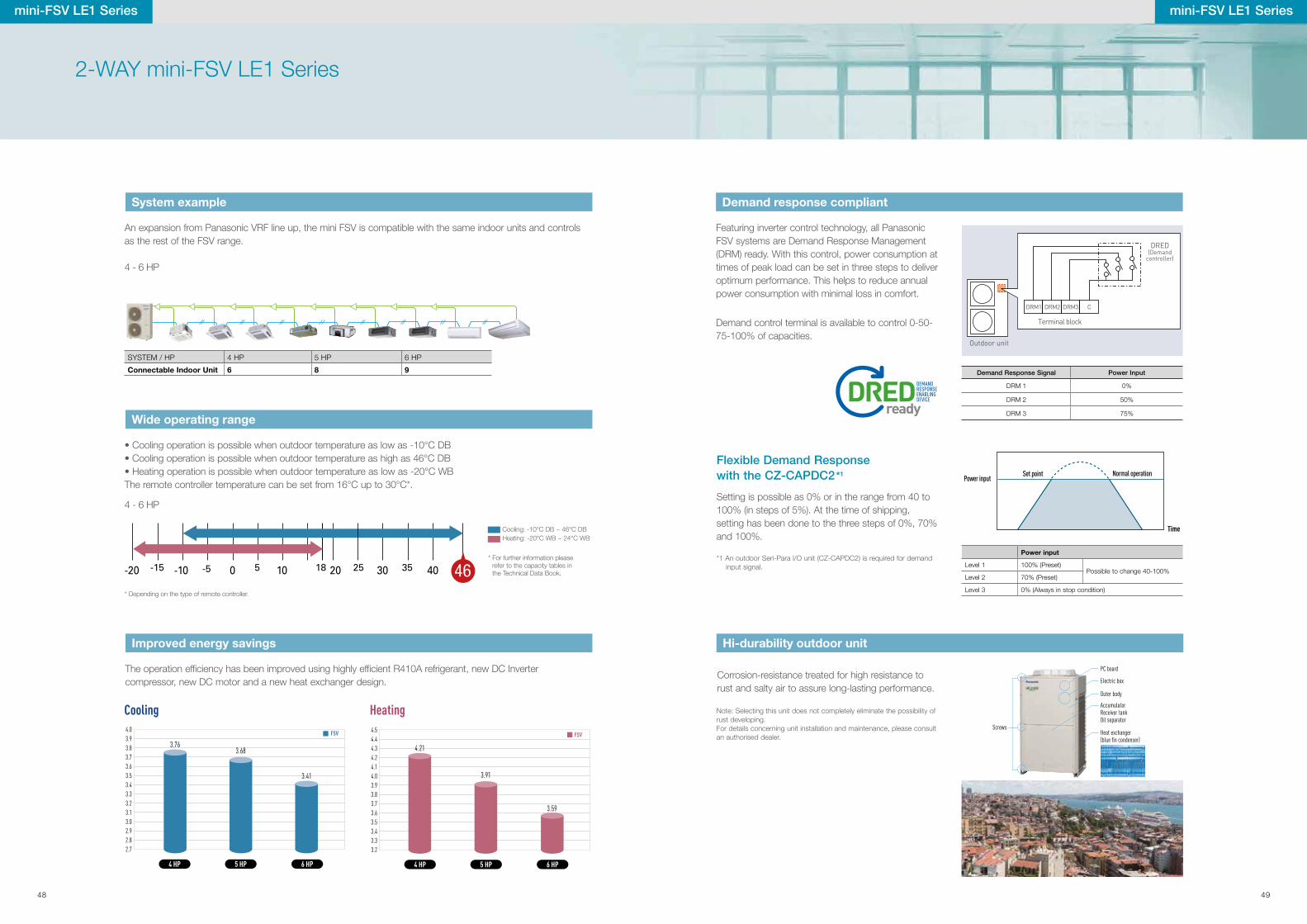
An expansion from Panasonic VRF line up, the mini FSV is compatible with the same indoor units and controls as the rest of the FSV range.
mini-FSV LE1 Series
SYSTEM / HP 4 HP 5 HP 6 HP
Connectable Indoor Unit 6 8 9
Refrigerant pipe Control line
Wide operating range
System example
Improved energy savings
4.03.93.83.73.63.53.43.33.23.13.02.92.82.7
Cooling
5 HP4 HP
3.763.68
3.41
6 HP
FSV 4.54.44.34.24.14.03.93.83.73.63.53.43.33.2
Heating
5 HP4 HP
4.21
3.91
3.59
6 HP
FSV
The operation ef�ciency has been improved using highly ef�cient R410A refrigerant, new DC Inverter compressor, new DC motor and a new heat exchanger design.
2-WAY mini-FSV LE1 Series
• Cooling operation is possible when outdoor temperature as low as -10°C DB• Cooling operation is possible when outdoor temperature as high as 46°C DB• Heating operation is possible when outdoor temperature as low as -20°C WBThe remote controller temperature can be set from 16°C up to 30°C*.
Cooling: -10°C DB ~ 46°C DBHeating: -20°C WB ~ 24°C WB
4 - 6 HP
4 - 6 HP
* For further information please refer to the capacity tables in the Technical Data Book.
mini-FSV LE1 Series
* Depending on the type of remote controller.
Hi-durability outdoor unit
Corrosion-resistance treated for high resistance to rust and salty air to assure long-lasting performance.
Note: Selecting this unit does not completely eliminate the possibility of rust developing. For details concerning unit installation and maintenance, please consult an authorised dealer.
Setting is possible as 0% or in the range from 40 to 100% (in steps of 5%). At the time of shipping, setting has been done to the three steps of 0%, 70% and 100%.
Flexible Demand Response with the CZ-CAPDC2*1
*1 An outdoor Seri-Para l/O unit (CZ-CAPDC2) is required for demand input signal.
Power input
Level 1 100% (Preset)Possible to change 40-100%
Level 2 70% (Preset)
Level 3 0% (Always in stop condition)
Set point
Time
Normal operationPower input
Demand response compliant
Featuring inverter control technology, all Panasonic FSV systems are Demand Response Management (DRM) ready. With this control, power consumption at times of peak load can be set in three steps to deliver optimum performance. This helps to reduce annual power consumption with minimal loss in comfort.
Outdoor unit
CDRM1 DRM2 DRM3
Terminal block
DRED (Demand
controller)
Demand control terminal is available to control 0-50-75-100% of capacities.
Demand Response Signal Power Input
DRM 1 0%
DRM 2 50%
DRM 3 75%
Screws
PC board
Electric box
Outer body
AccumulatorReceiver tankOil separator
Heat exchanger (blue fin condenser)
48 49
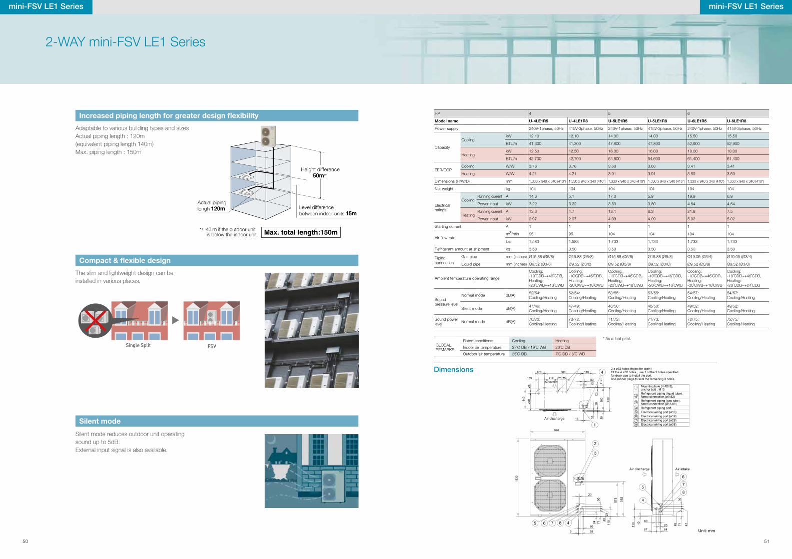
HP 4 5 6
Model name U-4LE1R5 U-4LE1R8 U-5LE1R5 U-5LE1R8 U-6LE1R5 U-6LE1R8
Power supply 240V-1phase, 50Hz 415V-3phase, 50Hz 240V-1phase, 50Hz 415V-3phase, 50Hz 240V-1phase, 50Hz 415V-3phase, 50Hz
Capacity
CoolingkW 12.10 12.10 14.00 14.00 15.50 15.50
BTU/h 41,300 41,300 47,800 47,800 52,900 52,900
HeatingkW 12.50 12.50 16.00 16.00 18.00 18.00
BTU/h 42,700 42,700 54,600 54,600 61,400 61,400
EER/COPCooling W/W 3.76 3.76 3.68 3.68 3.41 3.41
Heating W/W 4.21 4.21 3.91 3.91 3.59 3.59
Dimensions (H/W/D) mm 1,330 x 940 x 340 (410*) 1,330 x 940 x 340 (410*) 1,330 x 940 x 340 (410*) 1,330 x 940 x 340 (410*) 1,330 x 940 x 340 (410*) 1,330 x 940 x 340 (410*)
Net weight kg 104 104 104 104 104 104
Electrical ratings
CoolingRunning current A 14.6 5.1 17.0 5.9 19.9 6.9
Power input kW 3.22 3.22 3.80 3.80 4.54 4.54
HeatingRunning current A 13.3 4.7 18.1 6.3 21.8 7.5
Power input kW 2.97 2.97 4.09 4.09 5.02 5.02
Starting current A 1 1 1 1 1 1
Air �ow ratem3/min 95 95 104 104 104 104
L/s 1,583 1,583 1,733 1,733 1,733 1,733
Refrigerant amount at shipment kg 3.50 3.50 3.50 3.50 3.50 3.50
Piping connection
Gas pipe mm (inches) Ø15.88 (Ø5/8) Ø15.88 (Ø5/8) Ø15.88 (Ø5/8) Ø15.88 (Ø5/8) Ø19.05 (Ø3/4) Ø19.05 (Ø3/4)
Liquid pipe mm (inches) Ø9.52 (Ø3/8) Ø9.52 (Ø3/8) Ø9.52 (Ø3/8) Ø9.52 (Ø3/8) Ø9.52 (Ø3/8) Ø9.52 (Ø3/8)
Ambient temperature operating range
Cooling:-10˚CDB~+46˚CDB, Heating:-20˚CWB~+18˚CWB
Cooling:-10˚CDB~+46˚CDB, Heating:-20˚CWB~+18˚CWB
Cooling:-10˚CDB~+46˚CDB, Heating:-20˚CWB~+18˚CWB
Cooling:-10˚CDB~+46˚CDB, Heating:-20˚CWB~+18˚CWB
Cooling:-10˚CDB~+46˚CDB, Heating:-20˚CWB~+18˚CWB
Cooling:-10˚CDB~+46˚CDB, Heating:-20˚CDB~+24˚CDB
Sound pressure level
Normal mode dB(A) 52/54:Cooling/Heating
52/54:Cooling/Heating
53/55:Cooling/Heating
53/55:Cooling/Heating
54/57:Cooling/Heating
54/57:Cooling/Heating
Silent mode dB(A) 47/49:Cooling/Heating
47/49:Cooling/Heating
48/50:Cooling/Heating
48/50:Cooling/Heating
49/52:Cooling/Heating
49/52:Cooling/Heating
Sound power level Normal mode dB(A) 70/72:
Cooling/Heating70/72:Cooling/Heating
71/73:Cooling/Heating
71/73:Cooling/Heating
72/75:Cooling/Heating
72/75:Cooling/Heating
87 6420
60
10
110
7149 47
30
58
4
7
6
380
1820
20(1
0)
410
13
340
290
26
105 219 75 75 5013
20
1
4170 660 110
1330
940
60
110
71
4947
30
20
573
592
24
3
2
465 87
559
1
2
3
45678
Air discharge Air intake
Unit: mm
Air discharge
Air intake
2 x ø32 holes (holes for drain)Of the 4 ø32 holes , use 1 of the 2 holes specified for drain use to install the port.Use rubber plugs to seal the remaining 3 holes.
Mounting hole (4-R6.5),anchor bolt : M10Refrigerant piping (liquid tube),flared connection (ø9.52)Refrigerant piping (gas tube),flared connection (ø15.88)Refrigerant piping portElectrical wiring port (ø16)Electrical wiring port (ø19)Electrical wiring port (ø29)Electrical wiring port (ø38)
Dimensions
* As a foot print.
The slim and lightweight design can be installed in various places.
Adaptable to various building types and sizesActual piping length : 120m (equivalent piping length 140m)Max. piping length : 150m
FSVSingle Split
Silent mode reduces outdoor unit operating sound up to 5dB.External input signal is also available.
Silent mode
Compact & flexible design
Increased piping length for greater design flexibility
mini-FSV LE1 Series
GLOBAL REMARKS
Rated conditions: Cooling Heating
Indoor air temperature 27˚C DB / 19˚C WB 20˚C DB
Outdoor air temperature 35˚C DB 7˚C DB / 6˚C WB
2-WAY mini-FSV LE1 Series
Actual pipinglengh 120m Level difference
between indoor units 15m
Height difference50m*1
*1: 40 m if the outdoor unit is below the indoor unit. Max. total length:150m
mini-FSV LE1 Series
50 51
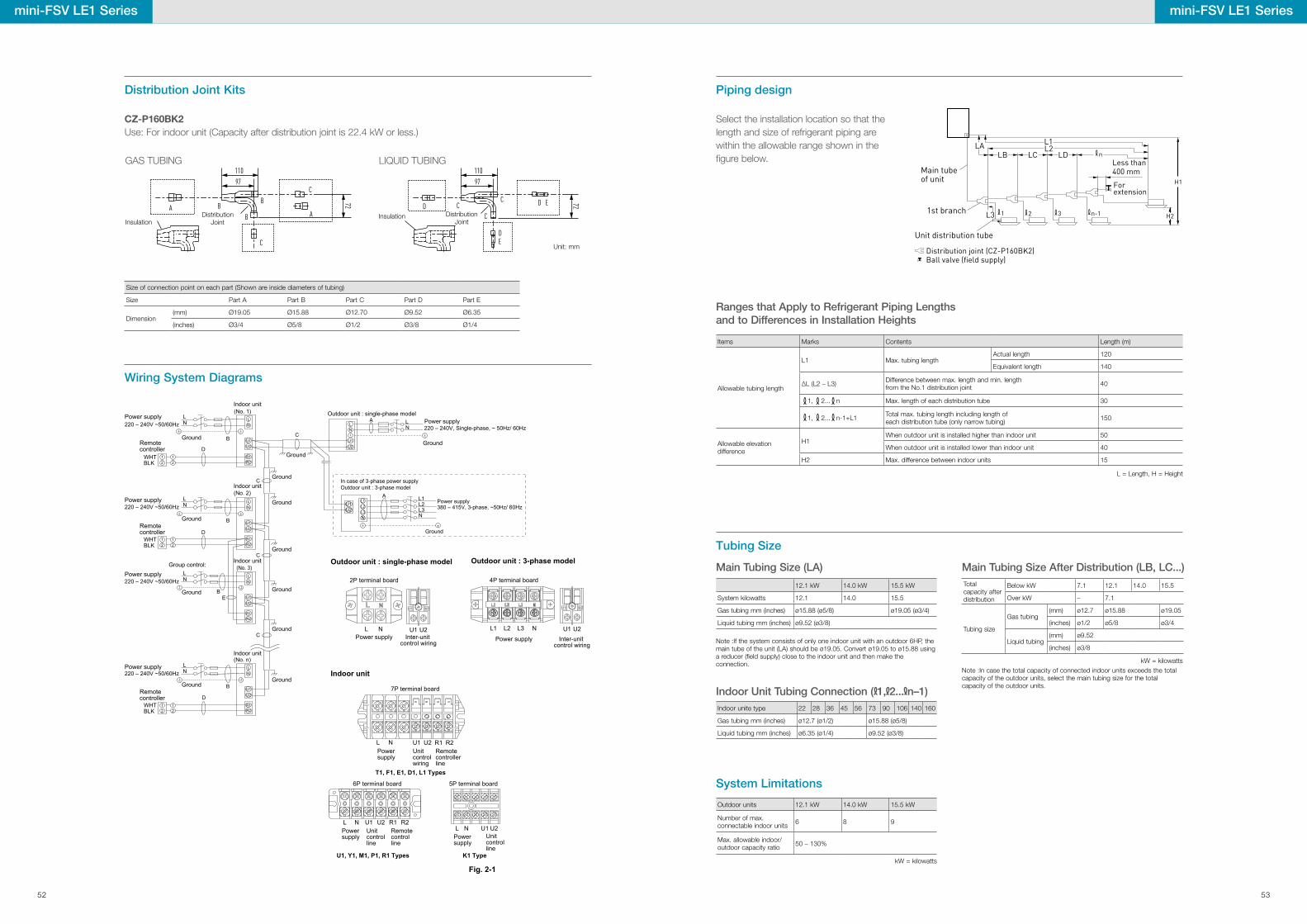
110
97
110
97
7272BA DB
BC
C
C D E
A
CDE
CH1
H2
LA L1L2
LDLCLB
L3
n
1 2 3 n-1
Main tube of unit
1st branch
Unit distribution tube
Less than 400 mm
For extension
Distribution joint (CZ-P160BK2)Ball valve (field supply)
A L1L2L3N
L1L2L3N
Ground
Power supply380 – 415V, 3-phase, ~50Hz/ 60HzU1
U2
In case of 3-phase power supplyOutdoor unit : 3-phase model
U1 U2 R1 R2
7P terminal board
T1, F1, E1, D1, L1 Types
Power supply
Remote controller line
Unit control wiring
Fig. 2-1
L N
L N U1 U2L N U1 U2 R1 R2
6P terminal board
Power supply Power
supply
Unit control line
Remote control line
U1, Y1, M1, P1, R1 Types
5P terminal board
K1 Type
Unitcontrolline
220 – 240V, Single-phase, ~ 50Hz/ 60Hz
U2U1
R2R1
LN
R2R1
R2R1
R2R1
21
21
U2U1
LN
U2U1
LN
U2U1
LN
21
21
21
D
E
C
B
LN
LN
LN
LN
21
B
B
B
C
D
D
C
C
220 – 240V ~50/60Hz
WHT BLK
WHT BLK
WHT BLK
220 – 240V ~50/60Hz
220 – 240V ~50/60Hz
220 – 240V ~50/60Hz
(No. 1)
(No. 2)
(No. n)
(No. 3)
U1U2
Power supply
Power supply
Power supply
Ground
Ground
Ground
Group control:
Remote controller
Remote controller
Remote controller
Power supply
Ground
Indoor unit
Indoor unit
Indoor unit
Indoor unit
Ground
Ground
Ground
Ground
Ground
Ground
Outdoor unit : single-phase model Power supply
Ground
Ground
Outdoor unit : single-phase model
Indoor unit
L N
2P terminal board
Power supplyU1 U2
Inter-unit control wiring
U1 U2
Outdoor unit : 3-phase model
L2L1 L3 N
4P terminal board
Power supplyU1 U2
Inter-unit control wiring
U1 U2
3-3. Wiring System DiagramsWiring System Diagrams
Piping design
Tubing Size
Distribution Joint Kits
Size of connection point on each part (Shown are inside diameters of tubing)
Size Part A Part B Part C Part D Part E
Dimension(mm) Ø19.05 Ø15.88 Ø12.70 Ø9.52 Ø6.35
(inches) Ø3/4 Ø5/8 Ø1/2 Ø3/8 Ø1/4
12.1 kW 14.0 kW 15.5 kW
System kilowatts 12.1 14.0 15.5
Gas tubing mm (inches) ø15.88 (ø5/8) ø19.05 (ø3/4)
Liquid tubing mm (inches) ø9.52 (ø3/8)
Items Marks Contents Length (m)
Allowable tubing length
L1 Max. tubing length Actual length 120
Equivalent length 140
∆L (L2 – L3) Difference between max. length and min. length from the No.1 distribution joint 40
1, 2... n Max. length of each distribution tube 30
1, 2... n-1+L1 Total max. tubing length including length of each distribution tube (only narrow tubing) 150
Allowable elevation difference
H1When outdoor unit is installed higher than indoor unit 50
When outdoor unit is installed lower than indoor unit 40
H2 Max. difference between indoor units 15
Outdoor units 12.1 kW 14.0 kW 15.5 kW
Number of max. connectable indoor units 6 8 9
Max. allowable indoor/outdoor capacity ratio 50 – 130%
Total capacity after distribution
Below kW 7.1 12.1 14.0 15.5
Over kW – 7.1
Tubing size
Gas tubing(mm) ø12.7 ø15.88 ø19.05
(inches) ø1/2 ø5/8 ø3/4
Liquid tubing(mm) ø9.52
(inches) ø3/8
Indoor unite type 22 28 36 45 56 73 90 106 140 160
Gas tubing mm (inches) ø12.7 (ø1/2) ø15.88 (ø5/8)
Liquid tubing mm (inches) ø6.35 (ø1/4) ø9.52 (ø3/8)
110
97
110
97
7272BA DB
BC
C
C D E
A
CDE
C
Distribution Joint
Distribution Joint
Unit: mm
InsulationInsulation
GAS TUBING LIQUID TUBING
CZ-P160BK2Use: For indoor unit (Capacity after distribution joint is 22.4 kW or less.)
Main Tubing Size (LA)
Ranges that Apply to Refrigerant Piping Lengthsand to Differences in Installation Heights
System Limitations
Main Tubing Size After Distribution (LB, LC...)
Note :If the system consists of only one indoor unit with an outdoor 6HP, the main tube of the unit (LA) should be ø19.05. Convert ø19.05 to ø15.88 using a reducer (�eld supply) close to the indoor unit and then make the connection. kW = kilowatts
L = Length, H = Height
kW = kilowatts
Note :In case the total capacity of connected indoor units exceeds the total capacity of the outdoor units, select the main tubing size for the total capacity of the outdoor units.
Select the installation location so that the length and size of refrigerant piping are within the allowable range shown in the �gure below.
mini-FSV LE1 Seriesmini-FSV LE1 Series
Indoor Unit Tubing Connection ( 1, 2... n–1)
52 53
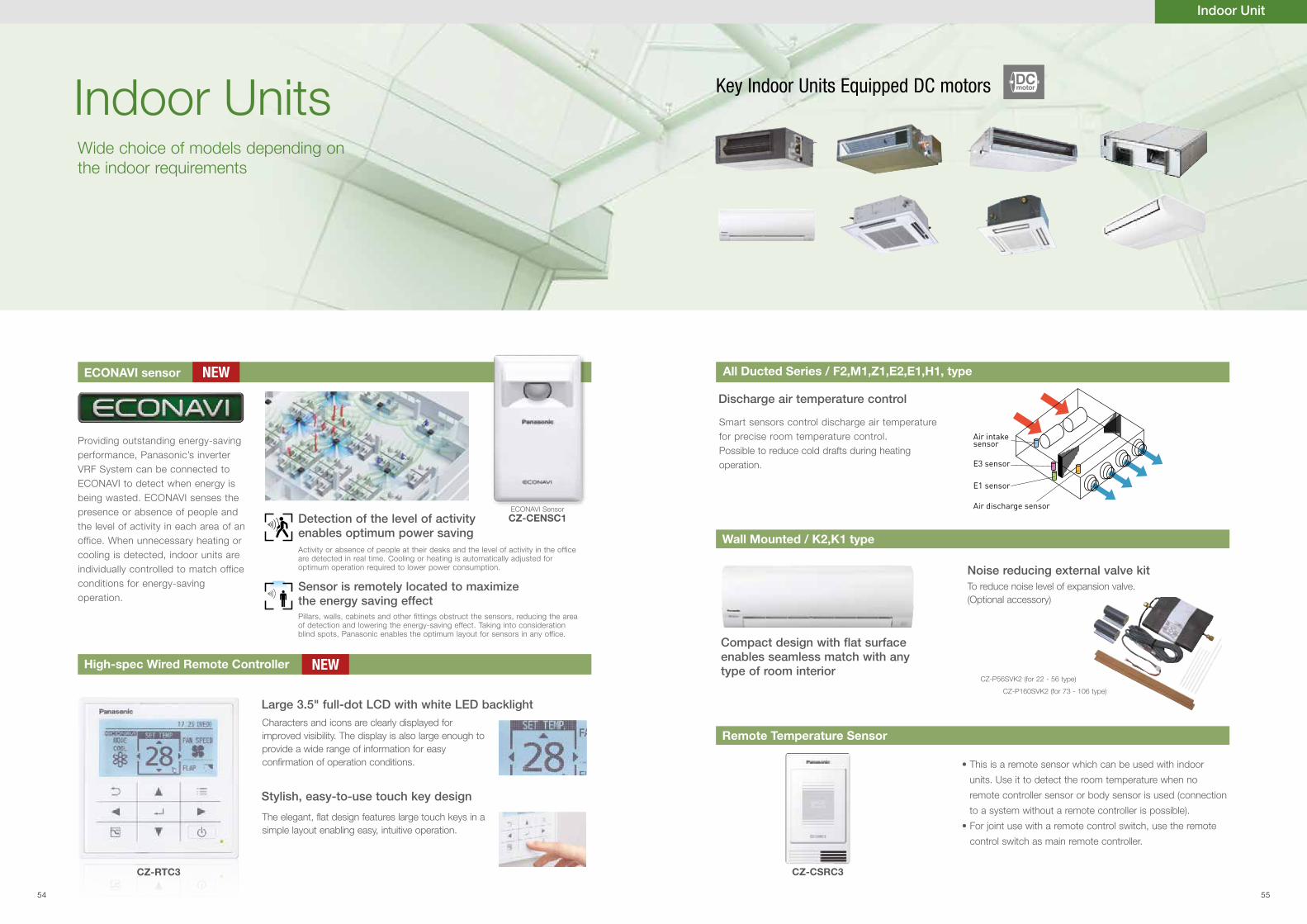
Indoor Unit
Compact design with �at surface enables seamless match with any type of room interior
Discharge air temperature control
Noise reducing external valve kit
Indoor UnitsWide choice of models depending on the indoor requirements
To reduce noise level of expansion valve.(Optional accessory)
Air intake sensor
Air discharge sensor
E3 sensor
E1 sensor
Smart sensors control discharge air temperature for precise room temperature control.Possible to reduce cold drafts during heating operation.
Wall Mounted / K2,K1 type
Remote Temperature Sensor
• This is a remote sensor which can be used with indoor
units. Use it to detect the room temperature when no
remote controller sensor or body sensor is used (connection
to a system without a remote controller is possible).
• For joint use with a remote control switch, use the remote
control switch as main remote controller.
CZ-P56SVK2 (for 22 - 56 type)
CZ-P160SVK2 (for 73 - 106 type)
Key Indoor Units Equipped DC motors
Large 3.5" full-dot LCD with white LED backlight
Stylish, easy-to-use touch key design
Characters and icons are clearly displayed for improved visibility. The display is also large enough to provide a wide range of information for easy con�rmation of operation conditions.
The elegant, flat design features large touch keys in a simple layout enabling easy, intuitive operation.
ECONAVI sensor All Ducted Series / F2,M1,Z1,E2,E1,H1, type
High-spec Wired Remote Controller
Providing outstanding energy-saving performance, Panasonic’s inverter VRF System can be connected to ECONAVI to detect when energy is being wasted. ECONAVI senses the presence or absence of people and the level of activity in each area of an office. When unnecessary heating or cooling is detected, indoor units are individually controlled to match office conditions for energy-saving operation.
Detection of the level of activityenables optimum power saving
Sensor is remotely located to maximize the energy saving effectPillars, walls, cabinets and other fittings obstruct the sensors, reducing the area of detection and lowering the energy-saving effect. Taking into consideration blind spots, Panasonic enables the optimum layout for sensors in any office.
Activity or absence of people at their desks and the level of activity in the office are detected in real time. Cooling or heating is automatically adjusted for optimum operation required to lower power consumption.
NEW
NEW
DCmotor
ECONAVI SensorCZ-CENSC1
CZ-RTC3 CZ-CSRC3
54 55
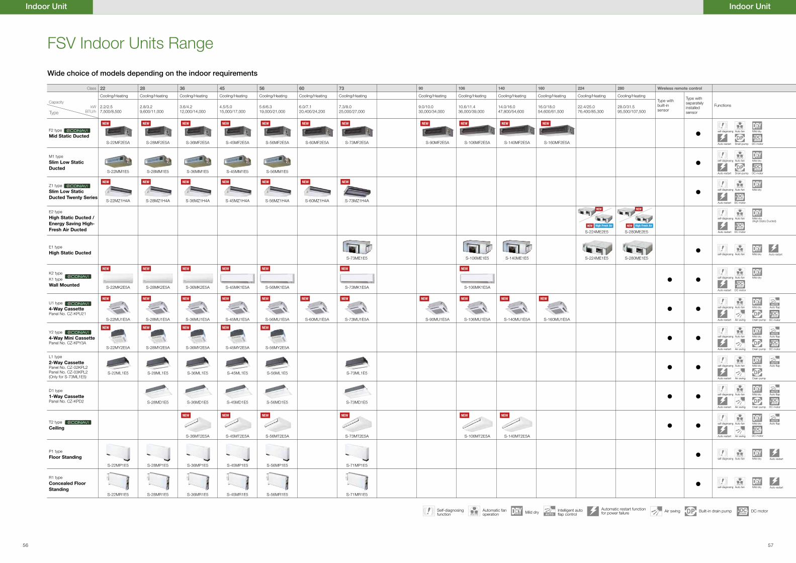
Class 22 28 36 45 56 60 73 90 106 140 160 224 280 Wireless remote control
Cooling/Heating Cooling/Heating Cooling/Heating Cooling/Heating Cooling/Heating Cooling/Heating Cooling/Heating Cooling/Heating Cooling/Heating Cooling/Heating Cooling/Heating Cooling/Heating Cooling/HeatingType with built-in sensor
Type with separately installed sensor
FunctionsCapacity
kWBTU/h
2.2/2.57,500/8,500
2.8/3.29,600/11,000
3.6/4.212,000/14,000
4.5/5.015,000/17,000
5.6/6.319,000/21,000
6.0/7.120,400/24,200
7.3/8.025,000/27,000
9.0/10.030,000/34,000
10.6/11.436,000/39,000
14.0/16.047,800/54,600
16.0/18.054,600/61,500
22.4/25.076,400/85,300
28.0/31.595,500/107,500
F2 type
Mid Static DuctedS-22MF2E5A S-28MF2E5A S-36MF2E5A S-45MF2E5A S-56MF2E5A S-60MF2E5A S-73MF2E5A S-90MF2E5A S-106MF2E5A S-140MF2E5A S-160MF2E5A
•
M1 type
Slim Low Static Ducted
S-22MM1E5 S-28MM1E5 S-36MM1E5 S-45MM1E5 S-56MM1E5•
Z1 type
Slim Low Static Ducted Twenty Series
S-22MZ1H4A S-28MZ1H4A S-36MZ1H4A S-45MZ1H4A S-56MZ1H4A S-60MZ1H4A S-73MZ1H4A•
E2 type
High Static Ducted / Energy Saving High-Fresh Air Ducted S-224ME2E5 S-280ME2E5
E1 type
High Static DuctedS-73ME1E5 S-106ME1E5 S-140ME1E5 S-224ME1E5 S-280ME1E5
•
K2 type
K1 type
Wall Mounted S-22MK2E5A S-28MK2E5A S-36MK2E5A S-45MK1E5A S-56MK1E5A S-73MK1E5A S-106MK1E5A• •
U1 type
4-Way CassettePanel No. CZ-KPU21
S-22MU1E5A S-28MU1E5A S-36MU1E5A S-45MU1E5A S-56MU1E5A S-60MU1E5A S-73MU1E5A S-90MU1E5A S-106MU1E5A S-140MU1E5A S-160MU1E5A
• •
Y2 type
4-Way Mini CassettePanel No. CZ-KPY3A
S-22MY2E5A S-28MY2E5A S-36MY2E5A S-45MY2E5A S-56MY2E5A
• •L1 type
2-Way CassettePanel No. CZ-02KPL2Panel No. CZ-03KPL2(Only for S-73ML1E5)
S-22ML1E5 S-28ML1E5 S-36ML1E5 S-45ML1E5 S-56ML1E5 S-73ML1E5• •
D1 type
1-Way CassettePanel No. CZ-KPD2 S-28MD1E5 S-36MD1E5 S-45MD1E5 S-56MD1E5 S-73MD1E5
• •
T2 type
Ceiling
S-36MT2E5A S-45MT2E5A S-56MT2E5A S-73MT2E5A S-106MT2E5A S-140MT2E5A
• •
P1 type
Floor Standing
S-22MP1E5 S-28MP1E5 S-36MP1E5 S-45MP1E5 S-56MP1E5 S-71MP1E5
•
R1 type
Concealed Floor Standing
S-22MR1E5 S-28MR1E5 S-36MR1E5 S-45MR1E5 S-56MR1E5 S-71MR1E5
•
NEW
NEW
NEW
NEW
NEW
NEW
NEW
NEW
NEW
NEW
NEW
NEW
NEW
NEW
NEW NEW
NEW
NEW NEW NEW
NEW NEW NEW NEW
NEW
NEW NEW
NEW NEW NEW
Indoor UnitIndoor Unit
FSV Indoor Units Range
Wide choice of models depending on the indoor requirements
Type
self-diagnosing
Auto restart
Auto fan
Air swing
Mild dry
Drain pump
Auto flap
self-diagnosing
Auto restart
Auto fan
Air swing
Mild dry
Drain pump
Auto flap
self-diagnosing
Auto restart
Auto fan
Air swing
Mild dry
Drain pump
Auto flap
self-diagnosing
Auto restart
Auto fan
Air swing
Mild dry
Drain pump
Auto flap
self-diagnosing
Auto restart
Auto fan
Air swing
Mild dry Auto flap
self-diagnosing
Auto restart
Auto fan Mild dry
self-diagnosing Auto restartAuto fan Mild dry
self-diagnosing Auto restartAuto fan Mild dry
Self-diagnosing function
Automatic restart function for power failure
Automatic fan operation
Air swingMild dry Built-in drain pump DC motorIntelligent auto flap control
self-diagnosing
Auto restart
Auto fan Mild dry
DCmotor
DC motor
DCmotor
DC motor
Drain pump
self-diagnosing
Auto restart
Auto fan Mild dry
Drain pump
self-diagnosing Auto restartAuto fan Mild dry
self-diagnosing
Auto restart
Auto fan
self-diagnosing
Auto restart
Auto fan Mild dry
Mild dry(High Static Ducted)
NEW
NEW
NEW
NEW
NEW
NEW
NEW
NEW
NEW
NEW
NEW
NEW
NEW
NEW
NEW NEW NEW NEW
NEWNEW High Fresh AirHigh Fresh Air
NEW
DCmotor
DC motor
DCmotor
DC motor
DCmotor
DC motor
DCmotor
DC motor
DCmotor
DC motor
DCmotor
DC motor
DCmotor
DCmotor
DC motor
56 57
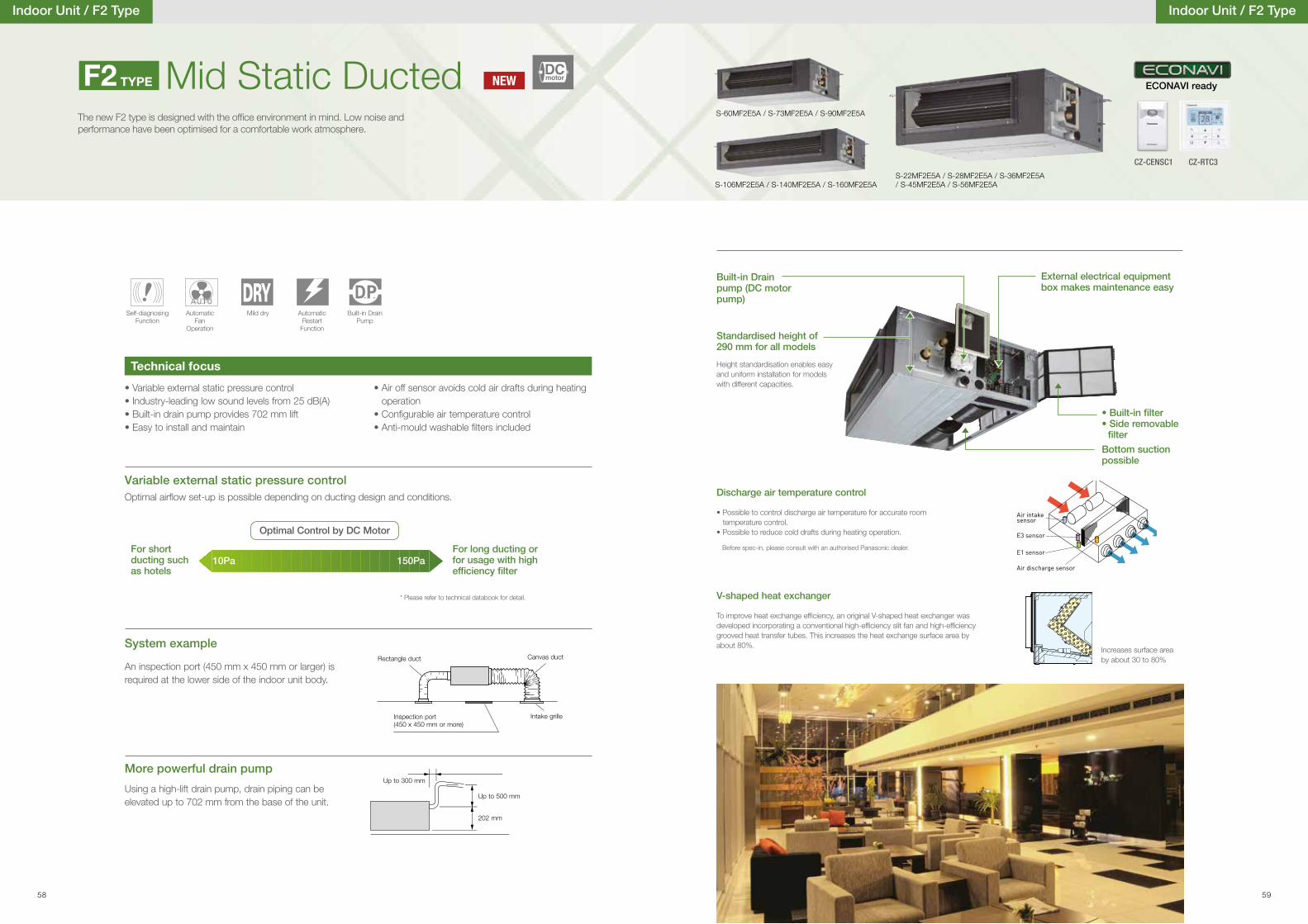
System example
Up to 300 mm
Up to 500 mm
202 mm
Mid Static DuctedThe new F2 type is designed with the of�ce environment in mind. Low noise andperformance have been optimised for a comfortable work atmosphere.
S-106MF2E5A / S-140MF2E5A / S-160MF2E5AS-22MF2E5A / S-28MF2E5A / S-36MF2E5A / S-45MF2E5A / S-56MF2E5A
Indoor Unit / F2 Type
• Variable external static pressure control• Industry-leading low sound levels from 25 dB(A)• Built-in drain pump provides 702 mm lift• Easy to install and maintain
• Air off sensor avoids cold air drafts during heating operation
• Con�gurable air temperature control• Anti-mould washable �lters included
Using a high-lift drain pump, drain piping can be elevated up to 702 mm from the base of the unit.
Optimal air�ow set-up is possible depending on ducting design and conditions.
An inspection port (450 mm x 450 mm or larger) is required at the lower side of the indoor unit body.
Rectangle duct Canvas duct
Intake grilleInspection port(450 x 450 mm or more)
Built-in Drain pump (DC motor pump)
• Built-in �lter• Side removable
�lter
Bottom suction possible
Air intake sensor
Air discharge sensor
E3 sensor
E1 sensor
Standardised height of 290 mm for all models
Height standardisation enables easy and uniform installation for models with different capacities.
Discharge air temperature control
V-shaped heat exchanger
• Possible to control discharge air temperature for accurate room temperature control.
• Possible to reduce cold drafts during heating operation.
To improve heat exchange ef�ciency, an original V-shaped heat exchanger was developed incorporating a conventional high-ef�ciency slit fan and high-ef�ciency grooved heat transfer tubes. This increases the heat exchange surface area by about 80%.
Before spec-in, please consult with an authorised Panasonic dealer.
External electrical equipment box makes maintenance easy
Technical focus
More powerful drain pump
Variable external static pressure control
Self-diagnosing Function
Automatic Fan
Operation
Mild dry AutomaticRestart
Function
Built-in Drain Pump
F2 TYPE
For short ducting such as hotels
For long ducting or for usage with high ef�ciency �lter
Optimal Control by DC Motor
10Pa 150Pa
* Please refer to technical databook for detail.
S-60MF2E5A / S-73MF2E5A / S-90MF2E5A
Indoor Unit / F2 Type
CZ-CENSC1
ECONAVI ready
CZ-RTC3
Increases surface area by about 30 to 80%
NEWDCmotor
58 59
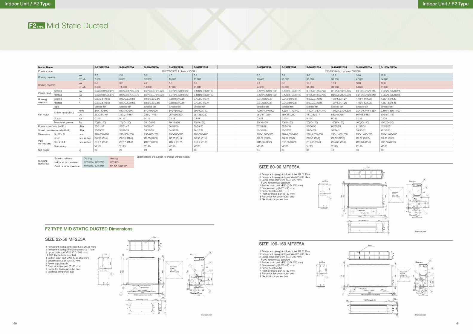
5
8
(150)
717133
150
636
700
758
3028 32
32
1400 27
3025
6
130
26
89
300
6511
3
70
6
4
1
9
3
2
290
23186
231402070
0
35
280
7
172
186
7727
154(75)
54
Inspectionaccess450 x 450(Field supply)
1192(Flange O.D.)
Filter
20-ø3holes
1467(Suspension bolt pitch)
150 x 7 = 1050
1000
32
33
32
758
3028
700
636
15021 21
8
5(150)
35
700
203025
6
130 70
140 2323
18627290
2
3
9
1
4
6
113
65 300
89
26
172
280
7
7727
186
(75)54 154
Inspectionaccess450 x 450(Field supply)
Filter
16-ø3holes
1067(Suspension bolt pitch)
792(Flange O.D.)
150 x 5 = 750
3232
3028
758
700
636
5
Filter
Inspectionaccess450 x 450(Field supply)
12-ø3holes
867(Suspension bolt pitch) (150)
(75)154
800150 x 3 = 450 7171
8
33
592(Flange O.D.)
35
700
203025
6
130
26
89
300
6511
3
70
6
4
1
9
3
2
29027
23
186
23140
172
280
7
7723
186
54
Dimensions: mm
Dimensions: mmDimensions: mm
Indoor Unit / F2 Type
Model Name S-22MF2E5A S-28MF2E5A S-36MF2E5A S-45MF2E5A S-56MF2E5A S-60MF2E5A S-73MF2E5A S-90MF2E5A S-106MF2E5A S-140MF2E5A S-160MF2E5A
Power source 220/230/240V, 1 phase - 50/60Hz 220/230/240V, 1 phase - 50/60Hz
Cooling capacitykW 2.2 2.8 3.6 4.5 5.6 6.0 7.3 9.0 10.6 14.0 16.0
BTU/h 7,500 9,600 12,000 15,000 19,000 20,400 25,000 30,000 36,000 47,800 54,600
Heating capacitykW 2.5 3.2 4.2 5.0 6.3 7.1 8.0 10.0 11.4 16.0 18.0
BTU/h 8,500 11,000 14,000 17,000 21,000 24,200 27,000 34,000 39,000 54,600 61,500
Power inputCooling kW 0.070/0.070/0.070 0.070/0.070/0.070 0.070/0.070/0.070 0.070/0.070/0.070 0.100/0.100/0.100 0.120/0.120/0.120 0.120/0.120/0.120 0.135/0.135/0.135 0.195/0.195/0.195 0.215/0.215/0.215 0.225/0.225/0.225
Heating kW 0.070/0.070/0.070 0.070/0.070/0.070 0.070/0.070/0.070 0.070/0.070/0.070 0.100/0.100/0.100 0.120/0.120/0.120 0.120/0.120/0.120 0.135/0.135/0.135 0.200/0.200/0.200 0.210/0.210/0.210 0.225/0.225/0.225
Running amperes
Cooling A 0.60/0.57/0.56 0.60/0.57/0.56 0.60/0.57/0.56 0.60/0.57/0.56 0.77/0.74/0.71 0.91/0.89/0.87 0.91/0.89/0.87 0.99/0.97/0.95 1.35/1.30/1.27 1.48/1.44/1.39 1.55/1.50/1.47
Heating A 0.60/0.57/0.56 0.60/0.57/0.56 0.60/0.57/0.56 0.60/0.57/0.56 0.77/0.74/0.71 0.91/0.89/0.87 0.91/0.89/0.87 0.99/0.97/0.95 1.37/1.34/1.29 1.46/1.42/1.38 1.55/1.50/1.46
Fan motor
Type Sirocco fan Sirocco fan Sirocco fan Sirocco fan Sirocco fan Sirocco fan Sirocco fan Sirocco fan Sirocco fan Sirocco fan Sirocco fan
Air �ow rate (H/M/L)m³/h 840/780/600 840/780/600 840/780/600 840/780/600 960/900/720 1,260/1,140/900 1,260/1,140/900 1,500/1,380/1,140 1,920/1,620/1,320 2,040/1,740/1,380 2,160/1,860/1,500
L/s 233/217/167 233/217/167 233/217/167 267/250/220 267/250/220 350/317/250 350/317/250 417/383/317 533/450/367 567/483/383 600/517/417
Output kW 0.119 0.119 0.119 0.119 0.119 0.124 0.124 0.124 0.235 0.235 0.235
External static pressure Pa 70(10-150) 70(10-150) 70(10-150) 70(10-150) 70(10-150) 70(10-150) 70(10-150) 70(10-150) 100(10-150) 100(10-150) 100(10-150)
Power sound level (H/M/L) dB(A) 55/51/47 55/51/47 55/51/47 56/54/50 56/54/50 57/54/48 57/54/48 59/56/50 60/56/53 61/57/54 62/58/55
Sound pressure sound (H/M/L) dB(A) 33/29/25 33/29/25 33/29/25 34/32/28 34/32/28 35/32/26 35/32/26 37/34/28 38/34/31 39/35/32 40/36/33
Dimensions H x W x D mm 290x800x700 290x800x700 290x800x700 290x800x700 290x800x700 290x1,000x700 290x1,000x700 290x1,000x700 290x1,400x700 290x1,400x700 290x1,400x700
Pipe connections
Liquid mm (inches) Ø6.35 (Ø1/4) Ø6.35 (Ø1/4) Ø6.35 (Ø1/4) Ø6.35 (Ø1/4) Ø6.35 (Ø1/4) Ø9.52 (Ø3/8) Ø9.52 (Ø3/8) Ø9.52 (Ø3/8) Ø9.52 (Ø3/8) Ø9.52 (Ø3/8) Ø9.52 (Ø3/8)
Gas 410 A mm (inches) Ø12.7 (Ø1/2) Ø12.7 (Ø1/2) Ø12.7 (Ø1/2) Ø12.7 (Ø1/2) Ø12.7 (Ø1/2) Ø15.88 (Ø5/8) Ø15.88 (Ø5/8) Ø15.88 (Ø5/8) Ø15.88 (Ø5/8) Ø15.88 (Ø5/8) Ø15.88 (Ø5/8)
Drain piping VP-25 VP-25 VP-25 VP-25 VP-25 VP-25 VP-25 VP-25 VP-25 VP-25 VP-25
Net weight kg 29 29 29 29 29 34 34 34 46 46 46
SIZE 22-56 MF2E5A
F2 TYPE MID STATIC DUCTED Dimensions
SIZE 60-90 MF2E5A
SIZE 106-160 MF2E5A
Mid Static DuctedF2 TYPE
Speci�cations are subject to change without notice.
GLOBAL REMARKS
Rated conditions: Cooling Heating
Indoor air temperature 27˚C DB / 19˚C WB 20˚C DB
Outdoor air temperature 35˚C DB / 24˚C WB 7˚C DB / 6˚C WB
1 Refrigerant piping joint (liquid tube) Ø9.52 Flare2 Refrigerant piping joint (gas tube) Ø15.88 Flare3 Upper drain port VP25 (O.D. Ø32 mm)
200 �exible hose supplied4 Bottom drain port VP25 (O.D. Ø32 mm)5 Suspension lug (4-12 × 30 mm)6 Power supply outlet7 Fresh air intake port (Ø150 mm)8 Flange for �exible air outlet duct9 Electrical component box
1 Refrigerant piping joint (liquid tube) Ø6.35 Flare2 Refrigerant piping joint (gas tube) Ø12.7 Flare3 Upper drain port VP25 (O.D. Ø32 mm)
200 �exible hose supplied4 Bottom drain port VP25 (O.D. Ø32 mm)5 Suspension lug (4-12 × 30 mm)6 Power supply outlet7 Fresh air intake port (Ø150 mm)8 Flange for �exible air outlet duct9 Electrical component box
Indoor Unit / F2 Type
60 61
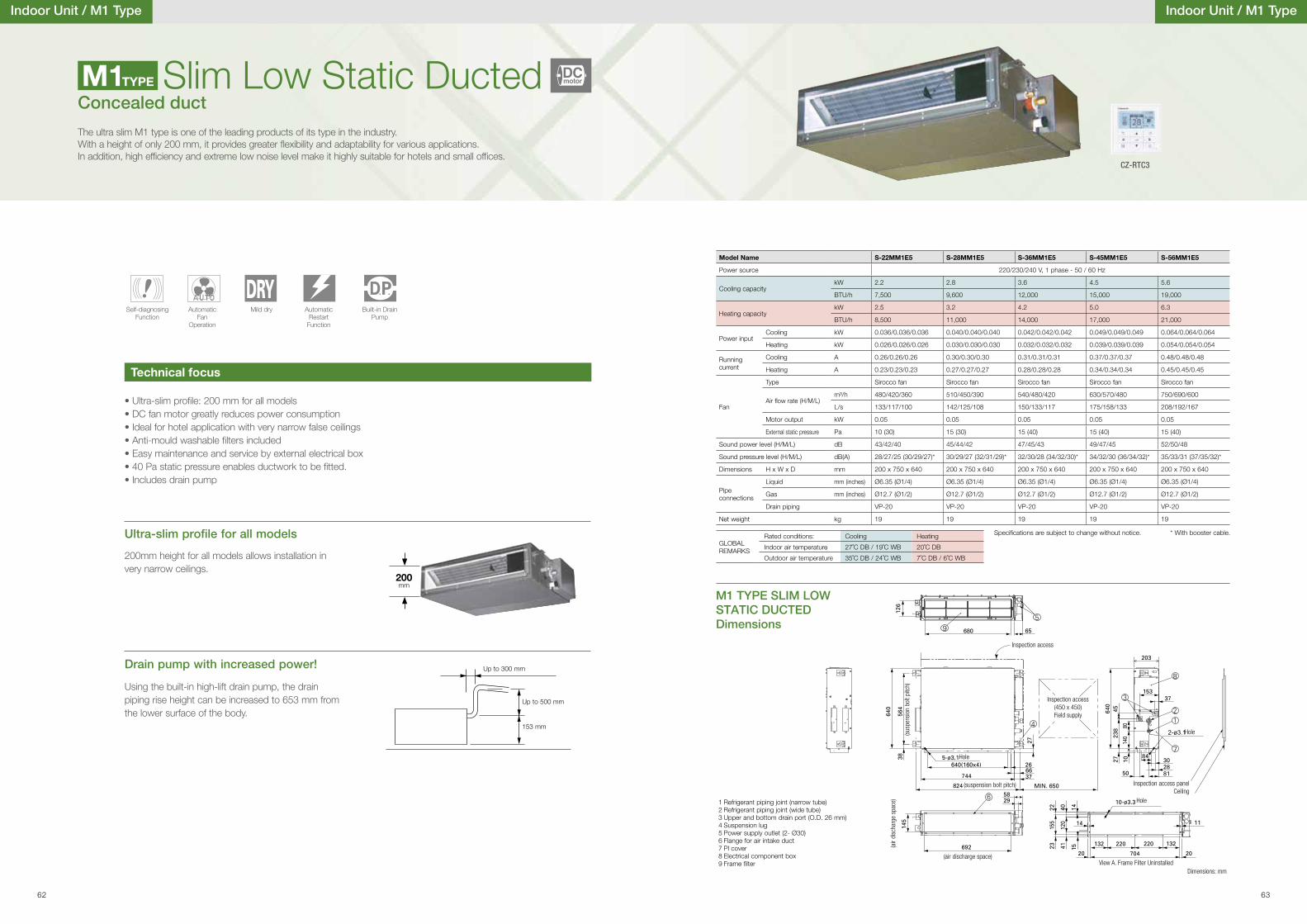
Indoor Unit / M1 Type
Ultra-slim pro�le for all models
Drain pump with increased power!
Using the built-in high-lift drain pump, the drain piping rise height can be increased to 653 mm from the lower surface of the body.
200mm height for all models allows installation in very narrow ceilings.
• Ultra-slim pro�le: 200 mm for all models• DC fan motor greatly reduces power consumption• Ideal for hotel application with very narrow false ceilings• Anti-mould washable �lters included• Easy maintenance and service by external electrical box• 40 Pa static pressure enables ductwork to be �tted.• Includes drain pump
Up to 300 mm
Up to 500 mm
153 mm
200mm
Slim Low Static DuctedConcealed duct
The ultra slim M1 type is one of the leading products of its type in the industry. With a height of only 200 mm, it provides greater �exibility and adaptability for various applications. In addition, high ef�ciency and extreme low noise level make it highly suitable for hotels and small of�ces.
Technical focus
Self-diagnosing Function
Automatic Fan
Operation
Mild dry AutomaticRestart
Function
Built-in Drain Pump
M1TYPE
1 Refrigerant piping joint (narrow tube) 2 Refrigerant piping joint (wide tube) 3 Upper and bottom drain port (O.D. 26 mm) 4 Suspension lug 5 Power supply outlet (2- Ø30) 6 Flange for air intake duct 7 Pl cover 8 Electrical component box 9 Frame �lter
(sus
pens
ion
bolt
pitc
h)
(suspension bolt pitch)
(air discharge space)View A. Frame Filter Uninstalled
(air
disc
harg
e sp
ace)
Hole
Hole
Hole
Inspection access
Inspection access panelCeiling
Inspection access(450 x 450)Field supply
Dimensions: mm
M1 TYPE SLIM LOW STATIC DUCTED Dimensions
Indoor Unit / M1 Type
Model Name S-22MM1E5 S-28MM1E5 S-36MM1E5 S-45MM1E5 S-56MM1E5
Power source 220/230/240 V, 1 phase - 50 / 60 Hz
Cooling capacitykW 2.2 2.8 3.6 4.5 5.6
BTU/h 7,500 9,600 12,000 15,000 19,000
Heating capacitykW 2.5 3.2 4.2 5.0 6.3
BTU/h 8,500 11,000 14,000 17,000 21,000
Power inputCooling kW 0.036/0.036/0.036 0.040/0.040/0.040 0.042/0.042/0.042 0.049/0.049/0.049 0.064/0.064/0.064
Heating kW 0.026/0.026/0.026 0.030/0.030/0.030 0.032/0.032/0.032 0.039/0.039/0.039 0.054/0.054/0.054
Running current
Cooling A 0.26/0.26/0.26 0.30/0.30/0.30 0.31/0.31/0.31 0.37/0.37/0.37 0.48/0.48/0.48
Heating A 0.23/0.23/0.23 0.27/0.27/0.27 0.28/0.28/0.28 0.34/0.34/0.34 0.45/0.45/0.45
Fan
Type Sirocco fan Sirocco fan Sirocco fan Sirocco fan Sirocco fan
Air �ow rate (H/M/L)m³/h 480/420/360 510/450/390 540/480/420 630/570/480 750/690/600
L/s 133/117/100 142/125/108 150/133/117 175/158/133 208/192/167
Motor output kW 0.05 0.05 0.05 0.05 0.05
External static pressure Pa 10 (30) 15 (30) 15 (40) 15 (40) 15 (40)
Sound power level (H/M/L) dB 43/42/40 45/44/42 47/45/43 49/47/45 52/50/48
Sound pressure level (H/M/L) dB(A) 28/27/25 (30/29/27)* 30/29/27 (32/31/29)* 32/30/28 (34/32/30)* 34/32/30 (36/34/32)* 35/33/31 (37/35/32)*
Dimensions H x W x D mm 200 x 750 x 640 200 x 750 x 640 200 x 750 x 640 200 x 750 x 640 200 x 750 x 640
Pipe connections
Liquid mm (inches) Ø6.35 (Ø1/4) Ø6.35 (Ø1/4) Ø6.35 (Ø1/4) Ø6.35 (Ø1/4) Ø6.35 (Ø1/4)
Gas mm (inches) Ø12.7 (Ø1/2) Ø12.7 (Ø1/2) Ø12.7 (Ø1/2) Ø12.7 (Ø1/2) Ø12.7 (Ø1/2)
Drain piping VP-20 VP-20 VP-20 VP-20 VP-20
Net weight kg 19 19 19 19 19
* With booster cable.Speci�cations are subject to change without notice.
GLOBAL REMARKS
Rated conditions: Cooling Heating
Indoor air temperature 27˚C DB / 19˚C WB 20˚C DB
Outdoor air temperature 35˚C DB / 24˚C WB 7˚C DB / 6˚C WB
CZ-RTC3
DCmotor
62 63

Indoor Unit / Z1 Type
Ultra-slim pro�le for all models
Drain pump with increased power! (optional)
Using the optional high-lift drain pump, the drain piping rise height can be increased to 700 mm from the drain pipe port.
200mm height for all models allows installation in very narrow ceilings.
• Ultra-slim pro�le: 200 mm for all models• DC fan motor greatly reduces power consumption• Ideal for hotel application with very narrow false ceilings• Easy maintenance and service by external electrical box• 29 Pa static pressure enables ductwork to be �tted.• Drain pump (optional)
200mm
Concealed duct
The ultra slim Z1 type is one of the leading products of its type in the industry. With a height of only 200 mm, it provides greater �exibility and adaptability for various applications. In addition, high ef�ciency and extreme low noise level make it highly suitable for hotels and small of�ces.
Technical focus
Self-diagnosing Function
Automatic Fan
Operation
Mild dry AutomaticRestart
Function
Z1 TYPE
CZ-73DMZ1
Z1 TYPE SLIM LOW STATIC DUCTED TWENTY SERIES Dimensions
Slim Low Static Ducted Twenty SeriesNEW
S-73MZ1H4AS-22MZ1H4A/ S-28MZ1H4A/ S-36MZ1H4A/ S-45MZ1H4A/ S-56MZ1H4A/ S-60MZ1H4A
Indoor Unit / Z1 Type
Model Name S-22MZ1H4A S-28MZ1H4A S-36MZ1H4A S-45MZ1H4A S-56MZ1H4A S-60MZ1H4A S-73MZ1H4A
Power source 220/230/240 V, 1 phase - 50 / 60 Hz
Cooling capacitykW 2.2 2.8 3.6 4.5 5.6 6.0 7.3
BTU/h 7,500 9,500 12,200 15,300 19,100 20,500 24,900
Heating capacitykW 2.5 3.2 4.2 5.1 6.4 7.1 8.0
BTU/h 8,500 10,900 14,300 17,400 21,800 24,200 27,300
Power inputCooling kW 0.075/0.075/0.075 0.080/0.080/0.080 0.085/0.085/0.085 0.095/0.095/0.095 0.100/0.100/0.100 0.100/0.100/0.100 0.125/0.125/0.125
Heating kW 0.075/0.075/0.075 0.080/0.080/0.080 0.085/0.085/0.085 0.095/0.095/0.095 0.100/0.100/0.100 0.100/0.100/0.100 0.125/0.125/0.125
Running current
Cooling A 0.50/0.47/0.45 0.55/0.52/0.50 0.60/0.57/0.55 0.70/0.68/0.65 0.75/0.72/0.70 0.75/0.72/0.70 0.80/0.78/0.75
Heating A 0.50/0.47/0.45 0.55/0.52/0.50 0.60/0.57/0.55 0.70/0.68/0.65 0.75/0.72/0.70 0.75/0.72/0.70 0.80/0.78/0.75
Fan
Type Sirroco fan Sirroco fan Sirroco fan Sirroco fan Sirroco fan Sirroco fan Sirroco fan
Air �ow rate (H/M/L)m³/h 480/420/360 600/540/420 600/540/420 690/630/510 720/660/540 870/750/630 1,080/840/660
L/s 133/117/100 167/150/117 167/150/117 192/175/142 200/183/150 242/208/175 300/233/183
Motor output kW 60 60 60 60 60 60 60
External static pressure Pa 10-30 10-30 10-30 10-30 10-30 10-30 10-30
Sound power level (H/M/L) dB 50/49/47 52/51/49 54/52/50 56/54/52 57/55/53 60/57/55 62/60/58
Sound pressure level (H/M/L) dB(A) 28/27/25 30/29/27 32/30/28 34/32/30 35/33/31 38/35/33 40/38/36
Dimensions H x W x D mm 200×830×500 200×830×500 200×830×500 200×830×500 200×830×500 200×830×500 200×1,050×500
Pipe connections
Liquid mm (inches) Ø6.35 (Ø1/4) Ø6.35 (Ø1/4) Ø6.35 (Ø1/4) Ø6.35 (Ø1/4) Ø6.35 (Ø1/4) Ø6.35 (Ø1/4) Ø9.52 (Ø3/8)
Gas mm (inches) Ø12.7 (Ø1/2) Ø12.7 (Ø1/2) Ø12.7 (Ø1/2) Ø12.7 (Ø1/2) Ø12.7 (Ø1/2) Ø12.7 (Ø1/2) Ø15.88 (Ø5/8)
Drain piping O.D. Ø20.5 mm / I.D. Ø15.5mm
O.D. Ø20.5 mm / I.D. Ø15.5mm
O.D. Ø20.5 mm / I.D. Ø15.5mm
O.D. Ø20.5 mm /I.D. Ø15.5mm
O.D. Ø20.5 mm / I.D. Ø15.5mm
O.D. Ø20.5 mm / I.D. Ø15.5mm
O.D. Ø20.5 mm / I.D. Ø15.5mm
Net weight kg 17 17 18 18 18 18 24
Speci�cations are subject to change without notice.
GLOBAL REMARKS
Rated conditions: Cooling Heating
Indoor air temperature 27˚C DB / 19˚C WB 20˚C DB
Outdoor air temperature 35˚C DB / 24˚C WB 7˚C DB / 6˚C WB
DCmotor
CZ-CENSC1
ECONAVI ready
CZ-RTC3
a) Refrigerant tubing joint (liquid tube)b) Refrigerant tubing joint (gas tube)c) Bottom drain port O.D.Ø20.5 mm / I.D. Ø15.5mmd) Suspension lug (4 – 12 × 30 mm)e) Power supply outlet f ) Flange for �exible air outlet ductg) Electrical component box
SIZE 22-60MZ1H4A SIZE 73MZ1H4A
g
d
cf
ab 500
123.5153.9
54.8
Air outlet duct side
19.3150
41.3
69
62 400.9 9.555.4117.4
200185
867.6830
797.6(Flange)715
780926.6
130.655
37.8
27
89.6
21.9
e
d
e
g
ab
fc
(Flange)
Air outlet duct side
200185
65845
40
38 453
102 55
1,0851,050
19962
411
30 154
14
16131
30 550
66.5
200
unit : mm
64 65
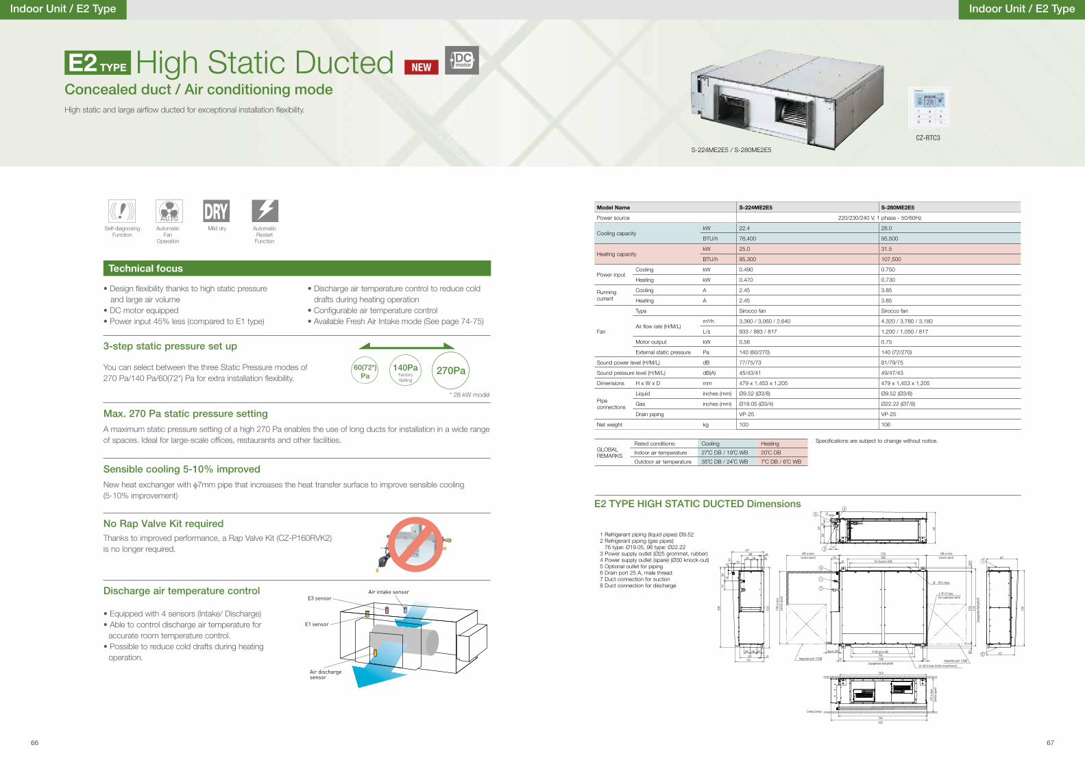
3-step static pressure set up
You can select between the three Static Pressure modes of 270 Pa/140 Pa/60(72*) Pa for extra installation �exibility. Factory
Setting
* 28 kW model
• Design �exibility thanks to high static pressure and large air volume• DC motor equipped• Power input 45% less (compared to E1 type)
• Discharge air temperature control to reduce cold drafts during heating operation
• Con�gurable air temperature control• Available Fresh Air Intake mode (See page 74-75)
High Static DuctedHigh static and large air�ow ducted for exceptional installation �exibility.
Discharge air temperature control
• Equipped with 4 sensors (Intake/ Discharge) • Able to control discharge air temperature for
accurate room temperature control.• Possible to reduce cold drafts during heating
operation.
Air intake sensor
Air dischargesensor
E3 sensor
E1 sensor
Max. 270 Pa static pressure setting
Sensible cooling 5-10% improved
No Rap Valve Kit required
A maximum static pressure setting of a high 270 Pa enables the use of long ducts for installation in a wide range of spaces. Ideal for large-scale of�ces, restaurants and other facilities.
Thanks to improved performance, a Rap Valve Kit (CZ-P160RVK2) is no longer required.
New heat exchanger with φ7mm pipe that increases the heat transfer surface to improve sensible cooling (5-10% improvement)
Technical focus
Self-diagnosing Function
Automatic Fan
Operation
Mild dry AutomaticRestart
Function
E2 TYPE
Indoor Unit / E2 Type
Concealed duct / Air conditioning mode
Indoor Unit / E2 Type
S-224ME2E5 / S-280ME2E5
E2 TYPE HIGH STATIC DUCTED Dimensions
67
1170
Approx.200
1100
1200 67
60
1310
14531334
5
3
4
65
77
479
264
467
27
100
43
41
5040
479
320
300
60100 100
1220
156
131
434
207
100
45
23
1205
1
(suspension bolt pitch)
(susp
ensio
n bolt
pitc
h)
600 Inspection port600 Inspection port
(for suspension bolts)
24-37×12 holes
6
132
26-
45
3.2 holes (entire circumference)
1100
or m
ore
(servi
ce sp
ace)
610 o
r mor
e
Ceiling Surface
(servi
ce sp
ace)
800 or more(service space)
600 or more(service space)
9649×100 pitch=900
60
3.2 holes
7
8
1138
467
422
10×10 pitch=1000
13101070
28-
1 Refrigerant piping (liquid pipes) Ø9.522 Refrigerant piping (gas pipes)
76 type: Ø19.05, 96 type: Ø22.223 Power supply outlet (Ø25 grommet, rubber)4 Power supply outlet (spare) (Ø30 knock-out)5 Optional outlet for piping6 Drain port 25 A, male thread7 Duct connection for suction8 Duct connection for discharge
Model Name S-224ME2E5 S-280ME2E5
Power source 220/230/240 V, 1 phase - 50/60Hz
Cooling capacitykW 22.4 28.0
BTU/h 76,400 95,500
Heating capacitykW 25.0 31.5
BTU/h 85,300 107,500
Power inputCooling kW 0.490 0.750
Heating kW 0.470 0.730
Running current
Cooling A 2.45 3.85
Heating A 2.45 3.85
Fan
Type Sirocco fan Sirocco fan
Air �ow rate (H/M/L)m³/h 3,360 / 3,060 / 2,640 4,320 / 3,780 / 3,180
L/s 933 / 883 / 817 1,200 / 1,050 / 817
Motor output kW 0.56 0.75
External static pressure Pa 140 (60/270) 140 (72/270)
Sound power level (H/M/L) dB 77/75/73 81/79/75
Sound pressure level (H/M/L) dB(A) 45/43/41 49/47/43
Dimensions H x W x D mm 479 x 1,453 x 1,205 479 x 1,453 x 1,205
Pipe connections
Liquid inches (mm) Ø9.52 (Ø3/8) Ø9.52 (Ø3/8)
Gas inches (mm) Ø19.05 (Ø3/4) Ø22.22 (Ø7/8)
Drain piping VP-25 VP-25
Net weight kg 100 106
Speci�cations are subject to change without notice.
GLOBAL REMARKS
Rated conditions: Cooling Heating
Indoor air temperature 27˚C DB / 19˚C WB 20˚C DB
Outdoor air temperature 35˚C DB / 24˚C WB 7˚C DB / 6˚C WB
270Pa140Pa60(72*)Pa
CZ-RTC3
NEWDCmotor
66 67
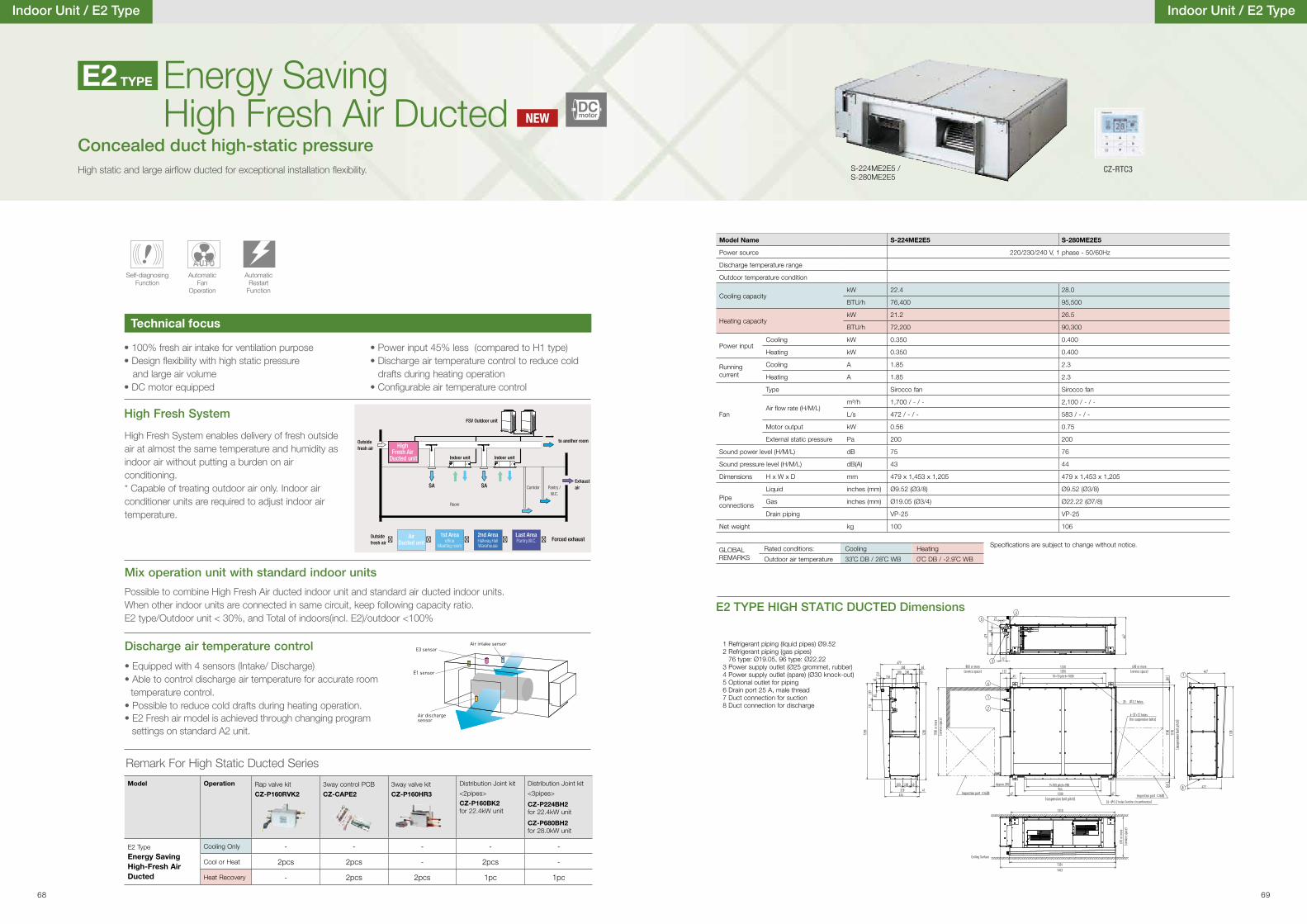
• 100% fresh air intake for ventilation purpose • Design �exibility with high static pressure and large air volume• DC motor equipped
• Power input 45% less (compared to H1 type)• Discharge air temperature control to reduce cold
drafts during heating operation• Con�gurable air temperature control
Energy Saving High Fresh Air Ducted
High static and large air�ow ducted for exceptional installation �exibility.
Technical focus
Self-diagnosing Function
Automatic Fan
Operation
AutomaticRestart
Function
E2 TYPE
Indoor Unit / E2 Type
Concealed duct high-static pressure
Indoor Unit / E2 Type
S-224ME2E5 /S-280ME2E5
E2 TYPE HIGH STATIC DUCTED Dimensions
1 Refrigerant piping (liquid pipes) Ø9.522 Refrigerant piping (gas pipes)
76 type: Ø19.05, 96 type: Ø22.223 Power supply outlet (Ø25 grommet, rubber)4 Power supply outlet (spare) (Ø30 knock-out)5 Optional outlet for piping6 Drain port 25 A, male thread7 Duct connection for suction8 Duct connection for discharge
Model Name S-224ME2E5 S-280ME2E5
Power source 220/230/240 V, 1 phase - 50/60Hz
Discharge temperature range
Outdoor temperature condition
Cooling capacitykW 22.4 28.0
BTU/h 76,400 95,500
Heating capacitykW 21.2 26.5
BTU/h 72,200 90,300
Power inputCooling kW 0.350 0.400
Heating kW 0.350 0.400
Running current
Cooling A 1.85 2.3
Heating A 1.85 2.3
Fan
Type Sirocco fan Sirocco fan
Air �ow rate (H/M/L)m³/h 1,700 / - / - 2,100 / - / -
L/s 472 / - / - 583 / - / -
Motor output kW 0.56 0.75
External static pressure Pa 200 200
Sound power level (H/M/L) dB 75 76
Sound pressure level (H/M/L) dB(A) 43 44
Dimensions H x W x D mm 479 x 1,453 x 1,205 479 x 1,453 x 1,205
Pipe connections
Liquid inches (mm) Ø9.52 (Ø3/8) Ø9.52 (Ø3/8)
Gas inches (mm) Ø19.05 (Ø3/4) Ø22.22 (Ø7/8)
Drain piping VP-25 VP-25
Net weight kg 100 106
Speci�cations are subject to change without notice.GLOBAL REMARKS
Rated conditions: Cooling Heating
Outdoor air temperature 33˚C DB / 28˚C WB 0˚C DB / -2.9˚C WB
High Fresh System
Mix operation unit with standard indoor units
High Fresh System enables delivery of fresh outside air at almost the same temperature and humidity as indoor air without putting a burden on air conditioning.* Capable of treating outdoor air only. Indoor air conditioner units are required to adjust indoor air temperature.
Possible to combine High Fresh Air ducted indoor unit and standard air ducted indoor units.When other indoor units are connected in same circuit, keep following capacity ratio.E2 type/Outdoor unit < 30%, and Total of indoors(incl. E2)/outdoor <100%
FSV Outdoor unit
Indoor unit Indoor unit
to another room
Exhaustair
Outside fresh air
Corridor Pantry /W.C.
SA SA
Outside fresh air
Forced exhaust
Room
� ����
High Fresh Air
Ducted unit
AirDucted unit
1st Areaoffice
Meeting room
2nd AreaHallway,HallWarehouse
Last AreaPantry,W.C.
CZ-RTC3
NEWDCmotor
Discharge air temperature control
• Equipped with 4 sensors (Intake/ Discharge) • Able to control discharge air temperature for accurate room
temperature control.• Possible to reduce cold drafts during heating operation.• E2 Fresh air model is achieved through changing program
Air intake sensor
Air dischargesensor
E3 sensor
E1 sensor
67
1170
Approx.200
1100
1200 67
60
1310
14531334
5
3
4
65
77
479
264
467
27
100
43
41
5040
479
320
300
60100 100
1220
156
131
434
207
100
45
23
1205
1
(suspension bolt pitch)
(susp
ensio
n bolt
pitc
h)
600 Inspection port600 Inspection port
(for suspension bolts)
24-37×12 holes
6
132
26-
45
3.2 holes (entire circumference)
1100
or m
ore
(servi
ce sp
ace)
610 o
r mor
e
Ceiling Surface
(servi
ce sp
ace)
800 or more(service space)
600 or more(service space)
9649×100 pitch=900
60
3.2 holes
7
8
1138
467
422
10×10 pitch=1000
13101070
28-
Model Operation Rap valve kit
CZ-P160RVK2
3way control PCB CZ-CAPE2
3way valve kit
CZ-P160HR3
Distribution Joint kit
<2pipes>
CZ-P160BK2for 22.4kW unit
Distribution Joint kit
<3pipes>
CZ-P224BH2for 22.4kW unit
CZ-P680BH2for 28.0kW unit
E2 Type
Energy Saving High-Fresh Air Ducted
Cooling Only - - - - -
Cool or Heat 2pcs 2pcs - 2pcs -
Heat Recovery - 2pcs 2pcs 1pc 1pc
Remark For High Static Ducted Series
68 69
settings on standard A2 unit.
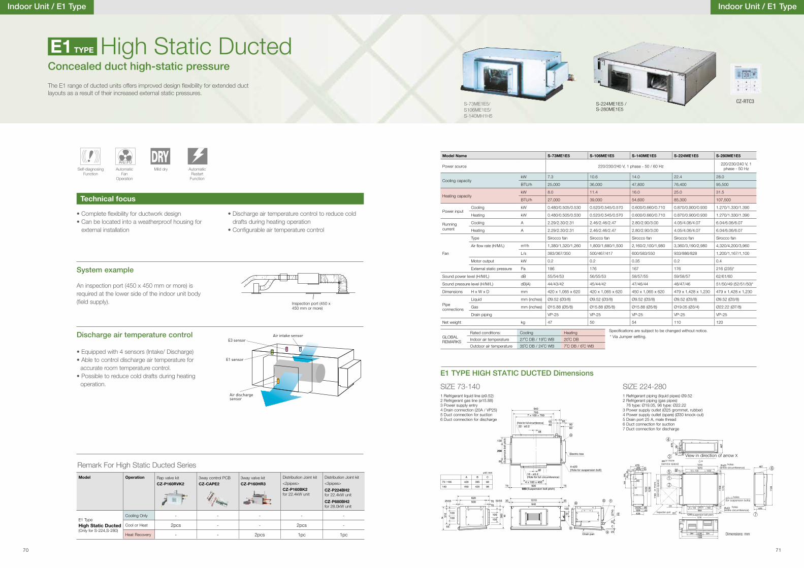
Indoor Unit / E1 Type
System example
An inspection port (450 x 450 mm or more) is required at the lower side of the indoor unit body (�eld supply).
• Complete �exibility for ductwork design• Can be located into a weatherproof housing for
external installation
• Discharge air temperature control to reduce cold drafts during heating operation
• Con�gurable air temperature control
Inspection port (450 x 450 mm or more)
Concealed duct high-static pressureHigh Static Ducted
The E1 range of ducted units offers improved design �exibility for extended duct layouts as a result of their increased external static pressures.
Discharge air temperature control
• Equipped with 4 sensors (Intake/ Discharge) • Able to control discharge air temperature for
accurate room temperature control.• Possible to reduce cold drafts during heating
operation.
Air intake sensor
Air dischargesensor
E3 sensor
E1 sensor
Technical focus
Self-diagnosing Function
Automatic Fan
Operation
Mild dry AutomaticRestart
Function
E1 TYPE
E1 TYPE HIGH STATIC DUCTED Dimensions
A 310
100100
300 B
505525 500 70 35940
35
15
81
80
290
(Sus
pens
ion b
olt p
itch)130
23
C55
6090
204055
500980 (Suspension bolt pitch)
4-ø20 (Hole for suspension bolt)
Drain pan
793940
48
4616 - ø3.2
Electric box
22 - ø3.2 (Hole for full circumference)
(Hole for full circumference)
(274
)100
1010
15
10
62055
55
100
100
73 / 106
140
A
420
450
B
395
425
C
68
98
unit: mm
7 × 100 = 700
4 × 100 = 400
Indoor Unit / E1 Type
Model Name S-73ME1E5 S-106ME1E5 S-140ME1E5 S-224ME1E5 S-280ME1E5
Power source 220/230/240 V, 1 phase - 50 / 60 Hz 220/230/240 V, 1 phase - 50 Hz
Cooling capacitykW 7.3 10.6 14.0 22.4 28.0
BTU/h 25,000 36,000 47,800 76,400 95,500
Heating capacitykW 8.0 11.4 16.0 25.0 31.5
BTU/h 27,000 39,000 54,600 85,300 107,500
Power inputCooling kW 0.480/0.505/0.530 0.520/0.545/0.570 0.600/0.660/0.710 0.870/0.900/0.930 1.270/1.330/1.390
Heating kW 0.480/0.505/0.530 0.520/0.545/0.570 0.600/0.660/0.710 0.870/0.900/0.930 1.270/1.330/1.390
Running current
Cooling A 2.29/2.30/2.31 2.46/2.46/2.47 2.80/2.90/3.00 4.05/4.06/4.07 6.04/6.06/6.07
Heating A 2.29/2.30/2.31 2.46/2.46/2.47 2.80/2.90/3.00 4.05/4.06/4.07 6.04/6.06/6.07
Fan
Type Sirocco fan Sirocco fan Sirocco fan Sirocco fan Sirocco fan
Air �ow rate (H/M/L) m³/h 1,380/1,320/1,260 1,800/1,680/1,500 2,160/2,100/1,980 3,360/3,190/2,980 4,320/4,200/3,960
L/s 383/367/350 500/467/417 600/583/550 933/886/828 1,200/1,167/1,100
Motor output kW 0.2 0.2 0.35 0.2 0.4
External static pressure Pa 186 176 167 176 216 (235)*
Sound power level (H/M/L) dB 55/54/53 56/55/53 58/57/55 59/58/57 62/61/60
Sound pressure level (H/M/L) dB(A) 44/43/42 45/44/42 47/46/44 48/47/46 51/50/49 (52/51/50)*
Dimensions H x W x D mm 420 x 1,065 x 620 420 x 1,065 x 620 450 x 1,065 x 620 479 x 1,428 x 1,230 479 x 1,428 x 1,230
Pipe connections
Liquid mm (inches) Ø9.52 (Ø3/8) Ø9.52 (Ø3/8) Ø9.52 (Ø3/8) Ø9.52 (Ø3/8) Ø9.52 (Ø3/8)
Gas mm (inches) Ø15.88 (Ø5/8) Ø15.88 (Ø5/8) Ø15.88 (Ø5/8) Ø19.05 (Ø3/4) Ø22.22 (Ø7/8)
Drain piping VP-25 VP-25 VP-25 VP-25 VP-25
Net weight kg 47 50 54 110 120
Speci�cations are subject to be changed without notice.* Via Jumper setting.GLOBAL
REMARKS
Rated conditions: Cooling Heating
Indoor air temperature 27˚C DB / 19˚C WB 20˚C DB
Outdoor air temperature 35˚C DB / 24˚C WB 7˚C DB / 6˚C WB
S-224ME1E5 /S-280ME1E5
1 Refrigerant liquid line (ø9.52)2 Refrigerant gas line (ø15.88)3 Power supply entry4 Drain connection (20A / VP25)5 Duct connection for suction6 Duct connection for discharge
1 Refrigerant piping (liquid pipes) Ø9.522 Refrigerant piping (gas pipes)
76 type: Ø19.05, 96 type: Ø22.223 Power supply outlet (Ø25 grommet, rubber)4 Power supply outlet (spare) (Ø30 knock-out)5 Drain port 25 A, male thread6 Duct connection for suction7 Duct connection for discharge
SIZE 73-140 SIZE 224-280
S-73ME1E5/S106ME1E5/S-140MH1H5
CZ-RTC3
Dimensions: mm
holes(entire circumference)
holes(entire circumference)
holes(for suspension bolts)
or more(service space)
or m
ore
(ser
vice
spa
ce)
(suspension bolt pitch)
View in direction of arrow X
Inspection port
pitch
Model Operation Rap valve kit
CZ-P160RVK2
3way control PCB CZ-CAPE2
3way valve kit
CZ-P160HR3
Distribution Joint kit
<2pipes>
CZ-P160BK2for 22.4kW unit
Distribution Joint kit
<3pipes>
CZ-P224BH2for 22.4kW unit
CZ-P680BH2for 28.0kW unit
E1 Type
High Static Ducted(Only for S-224,S-280)
Cooling Only - - - - -
Cool or Heat 2pcs - - 2pcs -
Heat Recovery - - 2pcs 1pc 1pc
Remark For High Static Ducted Series
70 71
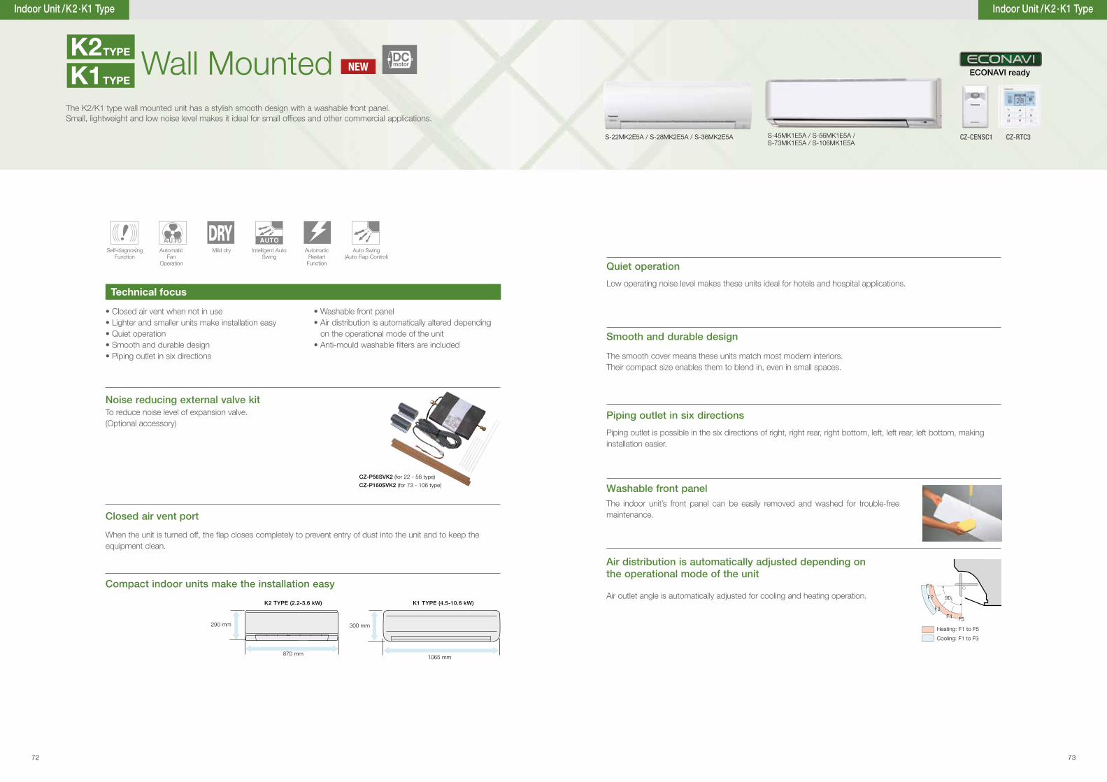
Indoor Unit /K2 ·K1 Type
• Closed air vent when not in use• Lighter and smaller units make installation easy• Quiet operation• Smooth and durable design• Piping outlet in six directions
• Washable front panel• Air distribution is automatically altered depending
on the operational mode of the unit• Anti-mould washable �lters are included
Air distribution is automatically adjusted depending on the operational mode of the unit
Closed air vent port
Quiet operation
Smooth and durable design
Piping outlet in six directions
Washable front panel
Compact indoor units make the installation easy
When the unit is turned off, the �ap closes completely to prevent entry of dust into the unit and to keep the equipment clean.
Low operating noise level makes these units ideal for hotels and hospital applications.
The smooth cover means these units match most modern interiors. Their compact size enables them to blend in, even in small spaces.
Piping outlet is possible in the six directions of right, right rear, right bottom, left, left rear, left bottom, making installation easier.
The indoor unit’s front panel can be easily removed and washed for trouble-free maintenance.
Air outlet angle is automatically adjusted for cooling and heating operation. F2
F3F4 F5
90¡
F1
F2
F3F4 F5
F1
Heating: F1 to F5
Cooling: F1 to F3
CZ-P56SVK2 (for 22 - 56 type)
CZ-P160SVK2 (for 73 - 106 type)
Noise reducing external valve kit
Wall MountedThe K2/K1 type wall mounted unit has a stylish smooth design with a washable front panel. Small, lightweight and low noise level makes it ideal for small of�ces and other commercial applications.
870 mm
290 mm 300 mm
1065 mm
To reduce noise level of expansion valve.(Optional accessory)
Technical focus
Self-diagnosing Function
Automatic Fan
Operation
Mild dry Intelligent Auto Swing
AutomaticRestart
Function
Auto Swing(Auto Flap Control)
S-45MK1E5A / S-56MK1E5A / S-73MK1E5A / S-106MK1E5A
S-22MK2E5A / S-28MK2E5A / S-36MK2E5A
K1TYPE
K2TYPE
K2 TYPE (2.2-3.6 kW) K1 TYPE (4.5-10.6 kW)
Indoor Unit /K2 ·K1 Type
NEWDCmotor
CZ-CENSC1
ECONAVI ready
CZ-RTC3
72 73
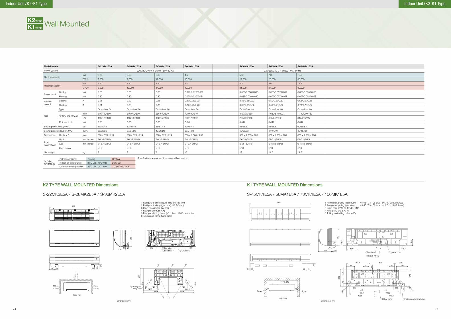
Indoor unit: S-45MK1E5 / 56MK1E5 / 73MK1E5 / 106MK1E5
1065
230 (2.5)197.4
140
158415
439.8
496.8
415
448.2
568.2
132
00259590543.483
68
300
48(Ø
80)
17.9
37.3
48
230.7
148.760 8
70 115.
9
115.
9
300
11 67
60
8667
(Ø80)
5cm 5cm
7.5cm
A
B
C
Refrigerant tubing (liquid tube)45-56 type 6.35 (flared)
Drain hose VP13 (outer dia. 18)D Rear panel (PL BACK)
Refrigerant tubing (gas tube)
E
73-106 type 9.52 (flared)45-56 type 12.7 (flared)
73-106 type 15.88 (flared)
Tubing and wiring holes ( 80)
unit: mm
870
214
290
1561
49
85
45
6095 60
183 190Gas tubeLiquid tube Drain Hose
100mm or more
65m
m
or m
ore
50mm or more
Front view
241.5Ø70
241.5128 128
Ø70
438.5 438.5
57 57
290
Tubing and wiring holes
6
45
5 5
312
5
5
Dimensions: mmDimensions: mm
1 Refrigerant tubing (liquid tube) ø6.35(�ared)2 Refrigerant tubing (gas tube) ø12.7(�ared)3 Drain hose (outer dia. ø16)4 Rear panel (PL BACK)5 Rear panel �xing holes (ø5 holes or 5X13 oval holes)6 Tubing and wiring holes (ø70)
2 Gas tube
1 Liquid tube
3 Drain hose
Front view
S-45MK1E5A / 56MK1E5A / 73MK1E5A / 106MK1E5AS-22MK2E5A / S-28MK2E5A / S-36MK2E5A
4 Rear panel 5 Tubing and wiring holes
K2 TYPE WALL MOUNTED Dimensions
1 Refrigerant piping (liquid tube) 45-56 / 73-106 type ø6.35 / ø9.52 (�ared)2 Refrigerant piping (gas tube) 45-56 / 73-106 type ø12.7 / ø15.88 (�ared)3 Drain hose VP13 (outer dia. ø18)4 Rear panel (PL BACK)5 Tubing and wiring holes (ø80)
Indoor Unit /K2 ·K1 Type
Wall Mounted
K1 TYPE WALL MOUNTED Dimensions
K1TYPE
K2TYPE
Indoor Unit /K2 ·K1 Type
Model Name S-22MK2E5A S-28MK2E5A S-36MK2E5A S-45MK1E5A S-56MK1E5A S-73MK1E5A S-106MK1E5A
Power source 220/230/240 V, 1 phase - 50 / 60 Hz 220/230/240 V, 1 phase - 50 / 60 Hz
Cooling capacitykW 2.20 2.80 3.60 4.5 5.6 7.3 10.6
BTU/h 7,500 9,600 12,300 15,000 19,000 25,000 36,000
Heating capacitykW 2.50 3.20 4.20 5.0 6.3 8.0 11.4
BTU/h 8,500 10,900 14,300 17,000 21,000 27,000 39,000
Power inputCooling kW 0.25 0.25 0.30 0.020/0.020/0.021 0.029/0.030/0.030 0.056/0.057/0.057 0.059/0.060/0.060
Heating kW 0.25 0.25 0.30 0.020/0.020/0.021 0.029/0.030/0.030 0.056/0.057/0.057 0.067/0.068/0.068
Running current
Cooling A 0.21 0.23 0.25 0.27/0.26/0.23 0.36/0.35/0.32 0.59/0.58/0.52 0.63/0.62/0.55
Heating A 0.21 0.23 0.25 0.27/0.26/0.23 0.36/0.35/0.32 0.59/0.58/0.52 0.70/0.70/0.62
Fan
Type Cross-�ow fan Cross-�ow fan Cross-�ow fan Cross-�ow fan Cross-�ow fan Cross-�ow fan Cross-�ow fan
Air �ow rate (H/M/L)m³/h 540/450/390 570/500/390 655/540/390 720/630/510 840/720/630 1,080/870/690 1,140/990/780
L/s 150/125/108 158/139/108 182/150/108 200/175/142 233/200/175 300/242/192 317/275/217
Motor output kW 0.03 0.03 0.03 0.047 0.047 0.047 0.047
Sound power level (H/M/L) dB 51/48/44 52/49/44 55/51/44 49/45/41 58/55/51 58/55/51 60/56/53
Sound pressure level (H/M/L) dB(A) 36/33/29 37/34/29 40/36/29 38/34/30 40/36/32 47/44/40 49/45/42
Dimensions H x W x D mm 290 x 870 x 214 290 x 870 x 214 290 x 870 x 214 300 x 1,065 x 230 300 x 1,065 x 230 300 x 1,065 x 230 300 x 1,065 x 230
Pipe connections
Liquid mm (inches) Ø6.35 (Ø1/4) Ø6.35 (Ø1/4) Ø6.35 (Ø1/4) Ø6.35 (Ø1/4) Ø6.35 (Ø1/4) Ø9.52 (Ø3/8) Ø9.52 (Ø3/8)
Gas mm (inches) Ø12.7 (Ø1/2) Ø12.7 (Ø1/2) Ø12.7 (Ø1/2) Ø12.7 (Ø1/2) Ø12.7 (Ø1/2) Ø15.88 (Ø5/8) Ø15.88 (Ø5/8)
Drain piping Ø16 Ø16 Ø16 Ø18 Ø18 Ø18 Ø18
Net weight kg 9 9 9 13 13 14.5 14.5
Specifications are subject to change without notice.GLOBAL REMARKS
Rated conditions: Cooling Heating
Indoor air temperature 27˚C DB / 19˚C WB 20˚C DB
Outdoor air temperature 35˚C DB / 24˚C WB 7˚C DB / 6˚C WB
74 75
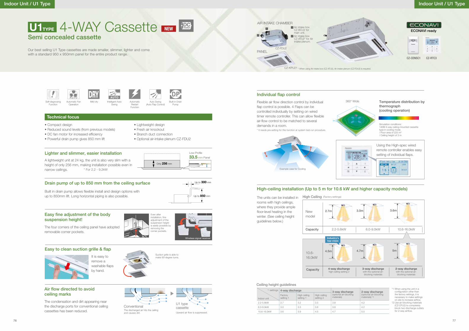
Up to 300 mm
Up to 850 mm
CZ-KPU21
PANEL
Drain pump of up to 850 mm from the ceiling surface
Even after installation, �ne adjustment of the suspension height is easily possible by removing the corner pockets.
suspension height!
The four corners of the ceiling panel have adopted removable corner pockets.
It is easy to remove a washable �aps by hand.
Suction grille is able to make 90-degree turns.
Wireless signal receiver
Self-diagnosing Function
Automatic Fan Operation
Mild dry Intelligent Auto Swing
AutomaticRestart
Function
Auto Swing(Auto Flap Control)
Built-in Drain Pump
4-WAY CassetteSemi concealed cassette
Our best selling U1 Type cassettes are made smaller, slimmer, lighter and come with a standard 950 x 950mm panel for the entire product range.
• Compact design• Reduced sound levels (from previous models)• DC fan motor for increased ef�ciency• Powerful drain pump gives 850 mm lift
• Lightweight design• Fresh air knockout• Branch duct connection• Optional air-intake plenum CZ-FDU2
Technical focus
ceiling marks
The condensation and dirt appearing near the discharge ports for conventional ceiling cassettes has been reduced.
U1 type cassetteUpward air �ow is suppressed.
U1TYPE
Built in drain pump allows �exible install and design options with up to 850mm lift. Long horizontal piping is also possible.
A lightweight unit at 24 kg, the unit is also very slim with a height of only 256 mm, making installation possible even in narrow ceilings.
Lighter and slimmer, easier installation
Only 256 mm
Low-Pro�le
33.5 mm Panel
ConventionalThe discharged air hits the ceiling and causes dirt.
Indoor Unit / U1 Type Indoor Unit / U1 Type
AIR INTAKE CHAMBER
Example case for Cooling
Flexible air �ow direction control by individual �ap control is possible. 4 Flaps can be controlled individually by setting on wired timer remote controller. This can allow �exible air-�ow control to be matched to several demands in a room.
Temperature distribution by thermograph (cooling operation)
Using the High-spec wired remote controller enables easy setting of individual �aps.
Simulation conditions: 140M 4-way ceiling-mounted cassette type in cooling mode/ Floor area of 225 m2
/ Ceiling height of 3 m
360° Wide
High-ceiling installation (Up to 5 m for 10.6 kW and higher capacity models)
2.2-5.6kW 6.0-9.0kW 10.6-16.0kW
(Factory settings)The units can be installed in rooms with high ceilings, where they provide ample �oor-level heating in the winter. (See ceiling height guidelines below.)
High Ceiling
New model
Capacity
* It needs pre-setting for this function at system test-run procedure.
*1 When using the unit in a configuration other than the factory settings, it is necessary to make settings on site to increase airflow.
*2 Use air-blocking materials (CZ-CFU2) to completely block two discharge outlets for 2-way air�ow.
Ceiling height guidelines
*1 settings
Indoor unit
4-way discharge 3-way discharge (optional air-blocking materials)
2-way discharge (optional air-blocking materials) *2
Factory setting 1
High ceiling setting 1
High ceiling setting 2
2.2-5.6kW 2.7 3.2 3.5 3.8 4.2
6.0-9.0kW 3.0 3.3 3.6 3.8 4.2
10.6-16.0kW 3.6 3.9 4.5 4.7 5.0
4-way dischargehigh ceiling setting 2
3-way dischargewith the optional air-blocking materials
2-way dischargewith the optional air-blocking materials
10.6-16.0kW
Capacity
1m
5m
3.6m
4.7m
3.0m
4.5m
2.7m
Industry’s top-class
1 Air intake box CZ-BCU2 for main unit.
* When using Air intake box (CZ-ATU2), Air intake plenum (CZ-FDU2) is required.
1
Air intake box CZ-ATU2* for Air intake plenum.
22
CZ-FDU2
NEWDCmotor
CZ-CENSC1
ECONAVI ready
CZ-RTC3
* For 2.2 - 9.2kW
76 77
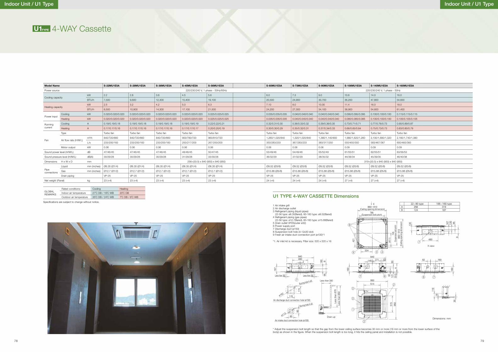
AX
X view
22~90 type 106~160 type256 319124 187
840480
180 B
160
421
(411
)
130 167
B
480
82 160
160
118
18
30
130
95
95
115
80
80
115
167
2
324
840
514950
515
950
271 50
5033
.512
142
145
Less than 300
Less
than
670
Less
than
850
ø162
ø113
B
8
5 3 4
7
77 6 9 7
2
2
2
2
1
860~910(Ceiling opening dimension)
860~
910
(Cei
ling
open
ing
dim
ensio
n)
786(Suspension bolt pitch)
745
(Sus
pens
ion bo
lt pitc
h)
Less than 35 Less than 35
Burring hole 4 - ø3
Burring hole 4 - ø3
Air discharge duct connection hole (ø150)
Air intake duct connection hole (ø100)Drain up
A
* Adjust the suspension bolt length so that the gap from the lower ceiling surface becomes 30 mm or more (18 mm or more from the lower surface of the body) as shown in the �gure. When the suspension bolt length is too long, it hits the ceiling panel and installation is not possible.
Dimensions: mm
Indoor Unit / U1 Type
4-WAY CassetteU1TYPE
*1: Air inlet kit is necessary. Filter size: 520 x 520 x 16
U1 TYPE 4-WAY CASSETTE Dimensions
1 Air intake grill2 Air discharge outlet3 Refrigerant piping (liquid pipes) 22-56 type: ø6.35(�ared), 60-160 type: ø9.52(�ared)4 Refrigerant piping (gas pipes) 22-56 type: ø12.7(�ared), 60-160 type: ø15.88(�ared)5 Drain outlet VP25(outer ø32)6 Power supply port7 Discharge duct (ø150)8 Suspension bolt hole (4-12x30 slot)9 Fresh air intake duct connection port (ø100)*1
Indoor Unit / U1 Type
Model Name S-22MU1E5A S-28MU1E5A S-36MU1E5A S-45MU1E5A S-56MU1E5A S-60MU1E5A S-73MU1E5A S-90MU1E5A S-106MU1E5A S-140MU1E5A S-160MU1E5A
Power source 220/230/240 V, 1 phase - 50Hz/60Hz 220/230/240 V, 1 phase - 50Hz
Cooling capacitykW 2.2 2.8 3.6 4.5 5.6 6.0 7.3 9.0 10.6 14.0 16.0
BTU/h 7,500 9,600 12,300 15,400 19,100 20,500 24,900 30,700 36,200 47,800 54,600
Heating capacitykW 2.5 3.2 4.2 5.0 6.3 7.10 8.0 10.00 11.4 16.0 18.0
BTU/h 8,500 10,900 14,300 17,100 21,500 24,200 27,300 34,100 38,900 54,600 61,400
Power inputCooling kW 0.020/0.020/0.020 0.020/0.020/0.020 0.020/0.020/0.020 0.020/0.020/0.020 0.025/0.025/0.025 0.035/0.035/0.035 0.040/0.040/0.040 0.040/0.040/0.040 0.095/0.095/0.095 0.100/0.100/0.100 0.115/0.115/0.115
Heating kW 0.020/0.020/0.020 0.020/0.020/0.020 0.020/0.020/0.020 0.020/0.020/0.020 0.025/0.025/0.025 0.035/0.035/0.035 0.040/0.040/0.040 0.040/0.040/0.040 0.085/0.085/0.085 0.100/0.100/0.100 0.105/0.105/0.105
Running current
Cooling A 0.19/0.19/0.18 0.19/0.19/0.18 0.19/0.19/0.18 0.19/0.19/0.19 0.22/0.22/0.21 0.32/0.31/0.30 0.36/0.33/0.32 0.39/0.36/0.35 0.73/0.71/0.71 0.77/0.76/0.73 0.90/0.89/0.87
Heating A 0.17/0.17/0.16 0.17/0.17/0.16 0.17/0.17/0.16 0.17/0.17/0.17 0.20/0.20/0.19 0.30/0.30/0.29 0.35/0.32/0.31 0.37/0.34/0.33 0.66/0.65/0.64 0.75/0.73/0.73 0.83/0.80/0.79
Fan
Type Turbo fan Turbo fan Turbo fan Turbo fan Turbo fan Turbo fan Turbo fan Turbo fan Turbo fan Turbo fan Turbo fan
Air �ow rate (H/M/L)m³/h 840/720/660 840/720/660 840/720/660 900/780/720 960/810/720 1,260/1,020/840 1,320/1,020/840 1,380/1,140/900 1,980/1,620/1,260 2,100/1,680/1,320 2,160/1,740/1,380
L/s 233/200/183 233/200/183 233/200/183 250/217/200 267/250/200 350/283/233 367/283/233 383/317/250 550/450/350 583/467/367 600/483/383
Motor output kW 0.06 0.06 0.06 0.06 0.06 0.06 0.06 0.06 0.09 0.09 0.09
Sound power level (H/M/L) dB 47/46/45 47/46/45 47/46/45 48/46/45 50/47/45 53/49/46 54/49/46 55/52/49 61/55/51 62/55/51 63/56/53
Sound pressure level (H/M/L) dB(A) 30/29/28 30/29/28 30/29/28 31/29/28 33/30/28 36/32/29 37/32/29 38/35/32 44/38/34 45/39/35 46/40/38
Dimensions H x W x D mm 256+(33.5) x 840 (950) x 840 (950) 319+(33.5) x 840 (950) x 840 (950)
Pipe connections
Liquid mm (inches) Ø6.35 (Ø1/4) Ø6.35 (Ø1/4) Ø6.35 (Ø1/4) Ø6.35 (Ø1/4) Ø6.35 (Ø1/4) Ø9.52 (Ø3/8) Ø9.52 (Ø3/8) Ø9.52 (Ø3/8) Ø9.52 (Ø3/8) Ø9.52 (Ø3/8) Ø9.52 (Ø3/8)
Gas mm (inches) Ø12.7 (Ø1/2) Ø12.7 (Ø1/2) Ø12.7 (Ø1/2) Ø12.7 (Ø1/2) Ø12.7 (Ø1/2) Ø15.88 (Ø5/8) Ø15.88 (Ø5/8) Ø15.88 (Ø5/8) Ø15.88 (Ø5/8) Ø15.88 (Ø5/8) Ø15.88 (Ø5/8)
Drain piping VP-25 VP-25 VP-25 VP-25 VP-25 VP-25 VP-25 VP-25 VP-25 VP-25 VP-25
Net weight (Panel) kg 23 (+4) 23 (+4) 23 (+4) 23 (+4) 23 (+4) 24 (+4) 24 (+4) 24 (+4) 27 (+4) 27 (+4) 27 (+4)
GLOBAL REMARKS
Rated conditions: Cooling Heating
Indoor air temperature 27˚C DB / 19˚C WB 20˚C DB
Outdoor air temperature 35˚C DB / 24˚C WB 7˚C DB / 6˚C WB
Speci�cations are subject to change without notice.
78 79
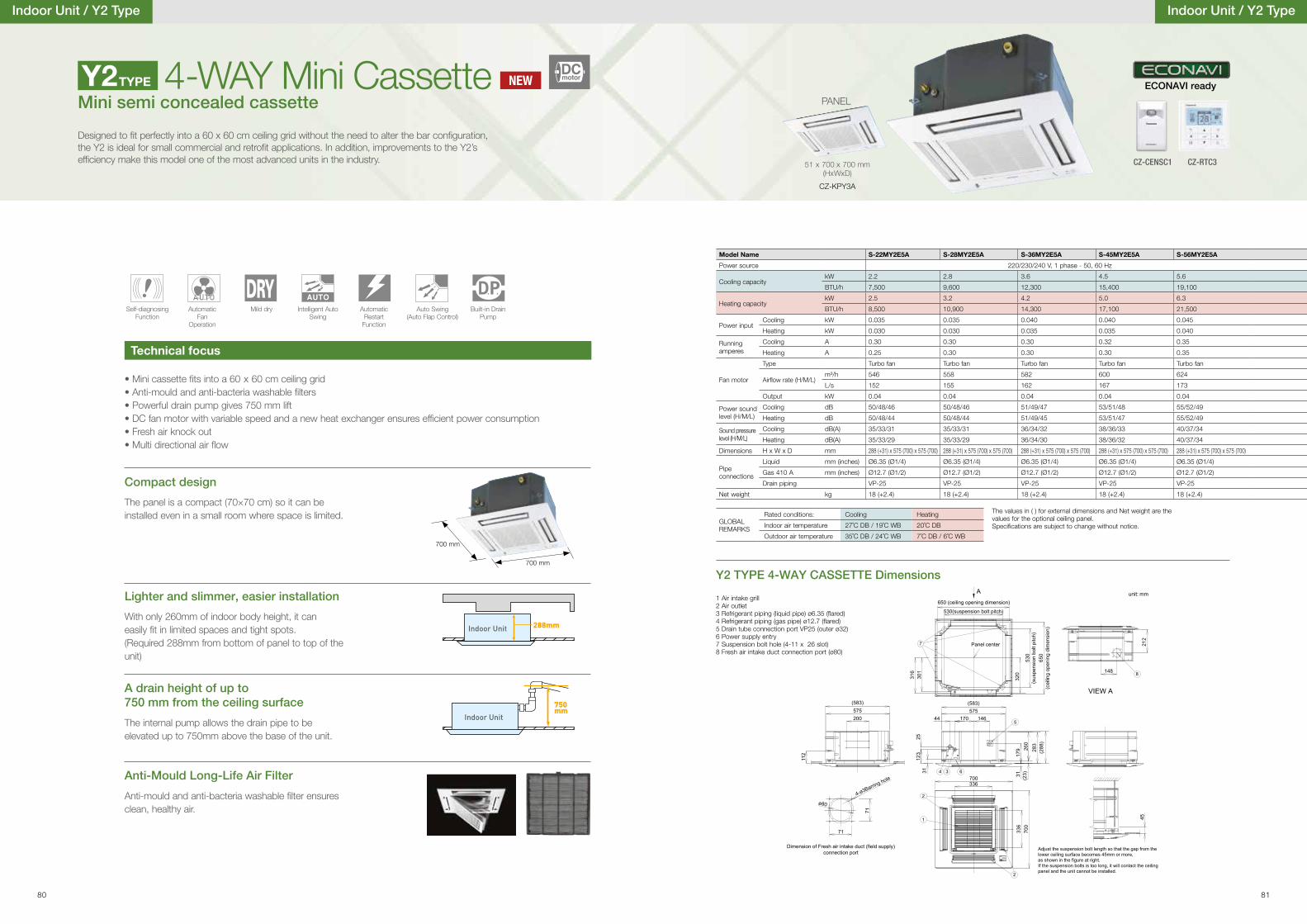
Indoor Unit / Y2 Type
Self-diagnosing Function
Automatic Fan
Operation
Mild dry Intelligent Auto Swing
AutomaticRestart
Function
Auto Swing(Auto Flap Control)
Built-in Drain Pump
Mini semi concealed cassette4-WAY Mini Cassette
Designed to �t perfectly into a 60 x 60 cm ceiling grid without the need to alter the bar con�guration, the Y2 is ideal for small commercial and retro�t applications. In addition, improvements to the Y2’s ef�ciency make this model one of the most advanced units in the industry.
Technical focus
Y2 TYPE 4-WAY CASSETTE Dimensions
Y2TYPE
Indoor Unit 288mm
750mm
Indoor Unit
700 mm
700 mm
• Mini cassette �ts into a 60 x 60 cm ceiling grid• Anti-mould and anti-bacteria washable �lters• Powerful drain pump gives 750 mm lift• DC fan motor with variable speed and a new heat exchanger ensures ef�cient power consumption• Fresh air knock out• Multi directional air �ow
The panel is a compact (70×70 cm) so it can be installed even in a small room where space is limited.
With only 260mm of indoor body height, it can easily �t in limited spaces and tight spots.(Required 288mm from bottom of panel to top of the unit)
The internal pump allows the drain pipe to be elevated up to 750mm above the base of the unit.
Anti-mould and anti-bacteria washable �lter ensures clean, healthy air.
Compact design
Lighter and slimmer, easier installation
A drain height of up to 750 mm from the ceiling surface
Anti-Mould Long-Life Air Filter
51 x 700 x 700 mm(HxWxD)
CZ-KPY3A
PANEL
unit: mm
2
2
1
Adjust the suspension bolt length so that the gap from the lower ceiling surface becomes 45mm or more, as shown in the figure at right. If the suspension bolts is too long, it will contact the ceiling panel and the unit cannot be installed.
25
(583)575
44 170
123
31
146
179 28
3(2
88)
31(2
3)26
0
(cei
ling
open
ing
dim
ensi
on)
(sus
pens
ion
bolt
pitc
h)
A650 (ceiling opening dimension)
530
650
530(suspension bolt pitch)
301
316
320
VIEW A
212
148
112
(583)575200
700336
336
700
Dimension of Fresh air intake duct (field supply)connection port
71
71
ø80
4-ø3Barring hole
45
4 3 6
5
7 Panel center
8
Indoor Unit / Y2 Type
1 Air intake grill2 Air outlet3 Refrigerant piping (liquid pipe) ø6.35 (�ared)4 Refrigerant piping (gas pipe) ø12.7 (�ared)5 Drain tube connection port VP25 (outer ø32)6 Power supply entry7 Suspension bolt hole (4-11 x 26 slot)8 Fresh air intake duct connection port (ø80)
The values in ( ) for external dimensions and Net weight are the values for the optional ceiling panel.Speci�cations are subject to change without notice.
GLOBAL REMARKS
Rated conditions: Cooling Heating
Indoor air temperature 27˚C DB / 19˚C WB 20˚C DB
Outdoor air temperature 35˚C DB / 24˚C WB 7˚C DB / 6˚C WB
Model Name S-22MY2E5A S-28MY2E5A S-36MY2E5A S-45MY2E5A S-56MY2E5A
Power source 220/230/240 V, 1 phase - 50, 60 Hz
Cooling capacitykW 2.2 2.8 3.6 4.5 5.6
BTU/h 7,500 9,600 12,300 15,400 19,100
Heating capacitykW 2.5 3.2 4.2 5.0 6.3
BTU/h 8,500 10,900 14,300 17,100 21,500
Power inputCooling kW 0.035 0.035 0.040 0.040 0.045
Heating kW 0.030 0.030 0.035 0.035 0.040
Running amperes
Cooling A 0.30 0.30 0.30 0.32 0.35
Heating A 0.25 0.30 0.30 0.30 0.35
Fan motor
Type Turbo fan Turbo fan Turbo fan Turbo fan Turbo fan
Air�ow rate (H/M/L)m³/h 546 558 582 600 624
L/s 152 155 162 167 173
Output kW 0.04 0.04 0.04 0.04 0.04
Power sound level (H/M/L)
Cooling dB 50/48/46 50/48/46 51/49/47 53/51/48 55/52/49
Heating dB 50/48/44 50/48/44 51/49/45 53/51/47 55/52/49
Sound pressure level (H/M/L)
Cooling dB(A) 35/33/31 35/33/31 36/34/32 38/36/33 40/37/34
Heating dB(A) 35/33/29 35/33/29 36/34/30 38/36/32 40/37/34
Dimensions H x W x D mm 288 (+31) x 575 (700) x 575 (700) 288 (+31) x 575 (700) x 575 (700) 288 (+31) x 575 (700) x 575 (700) 288 (+31) x 575 (700) x 575 (700) 288 (+31) x 575 (700) x 575 (700)
Pipe connections
Liquid mm (inches) Ø6.35 (Ø1/4) Ø6.35 (Ø1/4) Ø6.35 (Ø1/4) Ø6.35 (Ø1/4) Ø6.35 (Ø1/4)
Gas 410 A mm (inches) Ø12.7 (Ø1/2) Ø12.7 (Ø1/2) Ø12.7 (Ø1/2) Ø12.7 (Ø1/2) Ø12.7 (Ø1/2)
Drain piping VP-25 VP-25 VP-25 VP-25 VP-25
Net weight kg 18 (+2.4) 18 (+2.4) 18 (+2.4) 18 (+2.4) 18 (+2.4)
NEWDCmotor
CZ-CENSC1
ECONAVI ready
CZ-RTC3
80 81
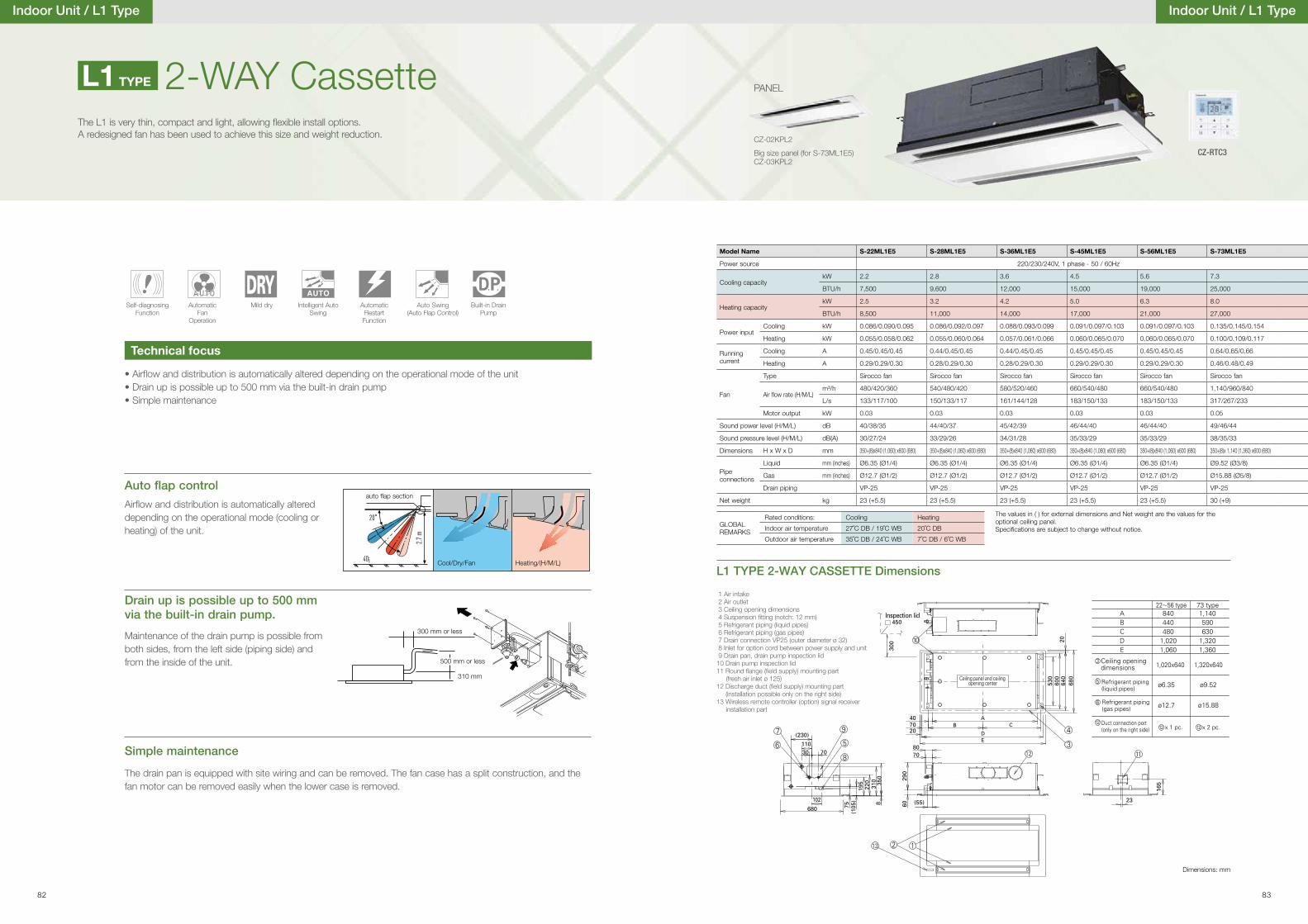
• Air�ow and distribution is automatically altered depending on the operational mode of the unit• Drain up is possible up to 500 mm via the built-in drain pump• Simple maintenance
Auto �ap control
Air�ow and distribution is automatically altered depending on the operational mode (cooling or heating) of the unit.
Drain up is possible up to 500 mm via the built-in drain pump.
Simple maintenance
Maintenance of the drain pump is possible from both sides, from the left side (piping side) and from the inside of the unit.
The drain pan is equipped with site wiring and can be removed. The fan case has a split construction, and the fan motor can be removed easily when the lower case is removed.
2.7 m
40¡
20
auto �ap section
Cool/Dry/Fan Heating/(H/M/L)
300 mm or less
500 mm or less
310 mm
2-WAY CassetteThe L1 is very thin, compact and light, allowing �exible install options. A redesigned fan has been used to achieve this size and weight reduction.
Indoor Unit / L1 Type
Technical focus
Self-diagnosing Function
Automatic Fan
Operation
Mild dry Intelligent Auto Swing
AutomaticRestart
Function
Auto Swing(Auto Flap Control)
Built-in Drain Pump
A
ED
B C
450
300
Inspection lid A 840440480
1,0201,060
1,140590630
1,3201,360
1,020x640
ø6.35 ø9.52
ø12.7 ø15.88
1,320x640
BCDE
73 type22 56 type
Ceiling opening dimensions
Refrigerant piping (liquid pipes)
Refrigerant piping (gas pipes)
Duct connection port (only on the right side) x 1 pc. x 2 pc.
Ceiling panel and ceiling opening center
40
530
600
640
680
20
7020
80
(230)
11030 70
680 75(1
05)
195
220
310 35
08102
70
23
165
(55)
290
60
L1 TYPE 2-WAY CASSETTE Dimensions
1 Air intake 2 Air outlet 3 Ceiling opening dimensions 4 Suspension �tting (notch: 12 mm) 5 Refrigerant piping (liquid pipes) 6 Refrigerant piping (gas pipes) 7 Drain connection VP25 (outer diameter ø 32) 8 Inlet for option cord between power supply and unit 9 Drain pan, drain pump inspection lid10 Drain pump inspection lid11 Round �ange (�eld supply) mounting part (fresh air inlet ø 125)12 Discharge duct (�eld supply) mounting part (installation possible only on the right side)13 Wireless remote controller (option) signal receiver installation part
Dimensions: mm
CZ-02KPL2
Big size panel (for S-73ML1E5) CZ-03KPL2
PANELL1 TYPE
Indoor Unit / L1 Type
Model Name S-22ML1E5 S-28ML1E5 S-36ML1E5 S-45ML1E5 S-56ML1E5 S-73ML1E5
Power source 220/230/240V, 1 phase - 50 / 60Hz
Cooling capacitykW 2.2 2.8 3.6 4.5 5.6 7.3
BTU/h 7,500 9,600 12,000 15,000 19,000 25,000
Heating capacitykW 2.5 3.2 4.2 5.0 6.3 8.0
BTU/h 8,500 11,000 14,000 17,000 21,000 27,000
Power inputCooling kW 0.086/0.090/0.095 0.086/0.092/0.097 0.088/0.093/0.099 0.091/0.097/0.103 0.091/0.097/0.103 0.135/0.145/0.154
Heating kW 0.055/0.058/0.062 0.055/0.060/0.064 0.057/0.061/0.066 0.060/0.065/0.070 0.060/0.065/0.070 0.100/0.109/0.117
Running current
Cooling A 0.45/0.45/0.45 0.44/0.45/0.45 0.44/0.45/0.45 0.45/0.45/0.45 0.45/0.45/0.45 0.64/0.65/0.66
Heating A 0.29/0.29/0.30 0.28/0.29/0.30 0.28/0.29/0.30 0.29/0.29/0.30 0.29/0.29/0.30 0.46/0.48/0.49
Fan
Type Sirocco fan Sirocco fan Sirocco fan Sirocco fan Sirocco fan Sirocco fan
Air �ow rate (H/M/L)m³/h 480/420/360 540/480/420 580/520/460 660/540/480 660/540/480 1,140/960/840
L/s 133/117/100 150/133/117 161/144/128 183/150/133 183/150/133 317/267/233
Motor output kW 0.03 0.03 0.03 0.03 0.03 0.05
Sound power level (H/M/L) dB 40/38/35 44/40/37 45/42/39 46/44/40 46/44/40 49/46/44
Sound pressure level (H/M/L) dB(A) 30/27/24 33/29/26 34/31/28 35/33/29 35/33/29 38/35/33
Dimensions H x W x D mm 350+(8)x840 (1,060) x600 (680) 350+(8)x840 (1,060) x600 (680) 350+(8)x840 (1,060) x600 (680) 350+(8)x840 (1,060) x600 (680) 350+(8)x840 (1,060) x600 (680) 350+(8)x 1,140 (1,360) x600 (680)
Pipe connections
Liquid mm (inches) Ø6.35 (Ø1/4) Ø6.35 (Ø1/4) Ø6.35 (Ø1/4) Ø6.35 (Ø1/4) Ø6.35 (Ø1/4) Ø9.52 (Ø3/8)
Gas mm (inches) Ø12.7 (Ø1/2) Ø12.7 (Ø1/2) Ø12.7 (Ø1/2) Ø12.7 (Ø1/2) Ø12.7 (Ø1/2) Ø15.88 (Ø5/8)
Drain piping VP-25 VP-25 VP-25 VP-25 VP-25 VP-25
Net weight kg 23 (+5.5) 23 (+5.5) 23 (+5.5) 23 (+5.5) 23 (+5.5) 30 (+9)
The values in ( ) for external dimensions and Net weight are the values for the optional ceiling panel.Speci�cations are subject to change without notice.
GLOBAL REMARKS
Rated conditions: Cooling Heating
Indoor air temperature 27˚C DB / 19˚C WB 20˚C DB
Outdoor air temperature 35˚C DB / 24˚C WB 7˚C DB / 6˚C WB
CZ-RTC3
82 83
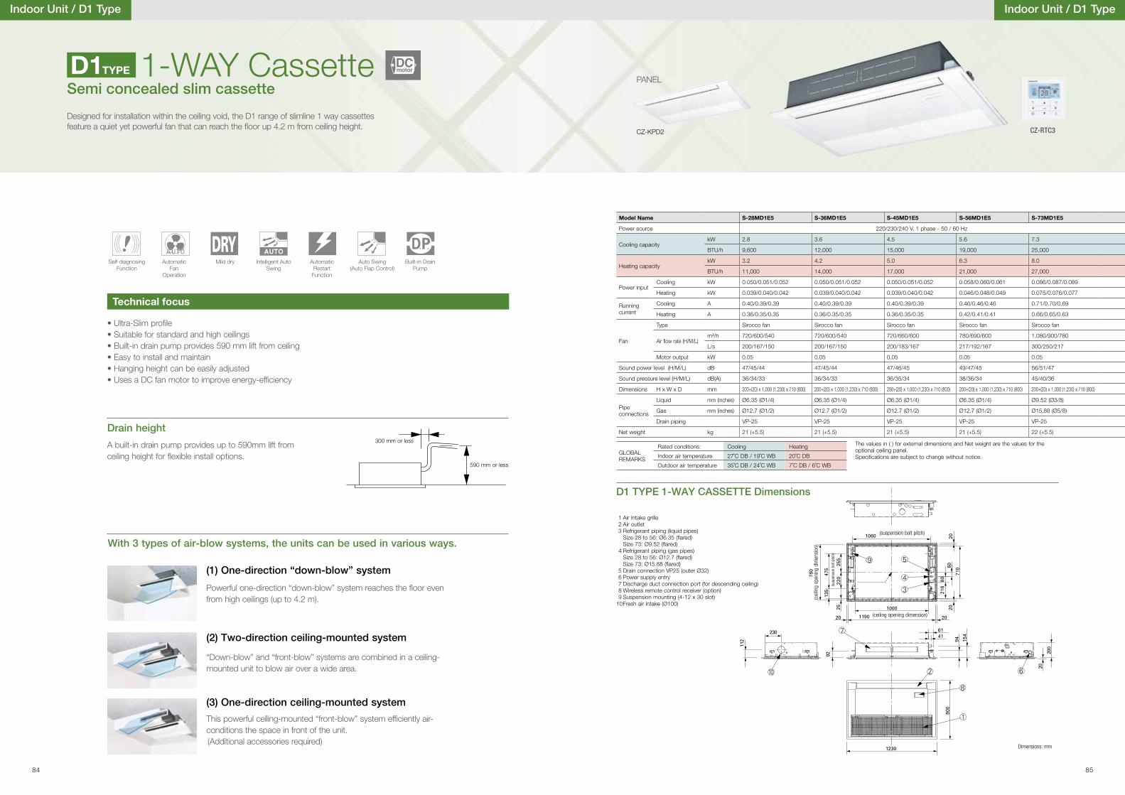
Indoor Unit / D1 Type
• Ultra-Slim pro�le• Suitable for standard and high ceilings• Built-in drain pump provides 590 mm lift from ceiling• Easy to install and maintain• Hanging height can be easily adjusted• Uses a DC fan motor to improve energy-ef�ciency
(1) One-direction “down-blow” system
Powerful one-direction “down-blow” system reaches the �oor even from high ceilings (up to 4.2 m).
A built-in drain pump provides up to 590mm lift from ceiling height for �exible install options.
(2) Two-direction ceiling-mounted system
“Down-blow” and “front-blow” systems are combined in a ceiling-mounted unit to blow air over a wide area.
(3) One-direction ceiling-mounted system
This powerful ceiling-mounted “front-blow” system ef�ciently air-conditions the space in front of the unit.(Additional accessories required)
Drain height
With 3 types of air-blow systems, the units can be used in various ways.
300 mm or less
590 mm or less
1-WAY CassetteSemi concealed slim cassette
Designed for installation within the ceiling void, the D1 range of slimline 1 way cassettes feature a quiet yet powerful fan that can reach the �oor up 4.2 m from ceiling height.
Technical focus
Self-diagnosing Function
Automatic Fan
Operation
Mild dry Intelligent Auto Swing
AutomaticRestart
Function
Auto Swing(Auto Flap Control)
Built-in Drain Pump
1 Air intake grille 2 Air outlet 3 Refrigerant piping (liquid pipes)
Size 28 to 56: Ø6.35 (�ared) Size 73: Ø9.52 (�ared)
4 Refrigerant piping (gas pipes) Size 28 to 56: Ø12.7 (�ared) Size 73: Ø15.88 (�ared)
5 Drain connection VP25 (outer Ø32) 6 Power supply entry 7 Discharge duct connection port (for descending ceiling) 8 Wireless remote control receiver (option) 9 Suspension mounting (4-12 x 30 slot) 10 Fresh air intake (Ø100)
Dimensions: mm
(ceiling opening dimension)
(cei
ling
open
ing
dim
ensi
on)
(suspension bolt pitch)
(sus
pens
ion
bolt
pitc
h)
D1TYPE
D1 TYPE 1-WAY CASSETTE Dimensions
CZ-KPD2
PANEL
Indoor Unit / D1 Type
Model Name S-28MD1E5 S-36MD1E5 S-45MD1E5 S-56MD1E5 S-73MD1E5
Power source 220/230/240 V, 1 phase - 50 / 60 Hz
Cooling capacitykW 2.8 3.6 4.5 5.6 7.3
BTU/h 9,600 12,000 15,000 19,000 25,000
Heating capacitykW 3.2 4.2 5.0 6.3 8.0
BTU/h 11,000 14,000 17,000 21,000 27,000
Power inputCooling kW 0.050/0.051/0.052 0.050/0.051/0.052 0.050/0.051/0.052 0.058/0.060/0.061 0.086/0.087/0.089
Heating kW 0.039/0.040/0.042 0.039/0.040/0.042 0.039/0.040/0.042 0.046/0.048/0.049 0.075/0.076/0.077
Running current
Cooling A 0.40/0.39/0.39 0.40/0.39/0.39 0.40/0.39/0.39 0.46/0.46/0.46 0.71/0.70/0.69
Heating A 0.36/0.35/0.35 0.36/0.35/0.35 0.36/0.35/0.35 0.42/0.41/0.41 0.66/0.65/0.63
Fan
Type Sirocco fan Sirocco fan Sirocco fan Sirocco fan Sirocco fan
Air �ow rate (H/M/L)m³/h 720/600/540 720/600/540 720/660/600 780/690/600 1,080/900/780
L/s 200/167/150 200/167/150 200/183/167 217/192/167 300/250/217
Motor output kW 0.05 0.05 0.05 0.05 0.05
Sound power level (H/M/L) dB 47/45/44 47/45/44 47/46/45 49/47/45 56/51/47
Sound pressure level (H/M/L) dB(A) 36/34/33 36/34/33 36/35/34 38/36/34 45/40/36
Dimensions H x W x D mm 200+(20) x 1,000 (1,230) x 710 (800) 200+(20) x 1,000 (1,230) x 710 (800) 200+(20) x 1,000 (1,230) x 710 (800) 200+(20) x 1,000 (1,230) x 710 (800) 200+(20) x 1,000 (1,230) x 710 (800)
Pipe connections
Liquid mm (inches) Ø6.35 (Ø1/4) Ø6.35 (Ø1/4) Ø6.35 (Ø1/4) Ø6.35 (Ø1/4) Ø9.52 (Ø3/8)
Gas mm (inches) Ø12.7 (Ø1/2) Ø12.7 (Ø1/2) Ø12.7 (Ø1/2) Ø12.7 (Ø1/2) Ø15.88 (Ø5/8)
Drain piping VP-25 VP-25 VP-25 VP-25 VP-25
Net weight kg 21 (+5.5) 21 (+5.5) 21 (+5.5) 21 (+5.5) 22 (+5.5)
The values in ( ) for external dimensions and Net weight are the values for the optional ceiling panel.Speci�cations are subject to change without notice.
GLOBAL REMARKS
Rated conditions: Cooling Heating
Indoor air temperature 27˚C DB / 19˚C WB 20˚C DB
Outdoor air temperature 35˚C DB / 24˚C WB 7˚C DB / 6˚C WB
CZ-RTC3
DCmotor
84 85
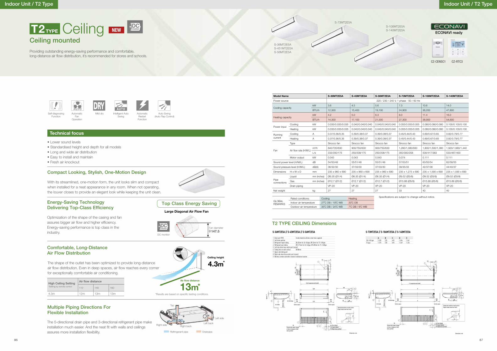
Model Name S-36MT2E5A S-45MT2E5A S-56MT2E5A S-73MT2E5A S-106MT2E5A S-140MT2E5A
Power source 220 / 230 / 240 V, 1 phase - 50 / 60 Hz
Cooling capacitykW 3.6 4.5 5.6 7.3 10.6 14.0
BTU/h 12,300 15,400 19,100 24,900 36,200 47,800
Heating capacitykW 4.2 5.0 6.3 8.0 11.4 16.0
BTU/h 14,300 17,100 21,500 27,300 38,900 54,600
Power inputCooling kW 0.035/0.035/0.035 0.040/0.040/0.040 0.040/0.040/0.040 0.055/0.055/0.055 0.080/0.080/0.080 0.100/0.100/0.100
Heating kW 0.035/0.035/0.035 0.040/0.040/0.040 0.040/0.040/0.040 0.055/0.055/0.055 0.080/0.080/0.080 0.100/0.100/0.100
Running current
Cooling A 0.37/0.36/0.35 0.39/0.38/0.37 0.39/0.38/0.37 0.45/0.44/0.43 0.69/0.67/0.65 0.82/0.79/0.77
Heating A 0.37/0.36/0.35 0.39/0.38/0.37 0.39/0.38/0.37 0.45/0.44/0.43 0.69/0.67/0.65 0.82/0.79/0.77
Fan
Type Sirocco fan Sirocco fan Sirocco fan Sirocco fan Sirocco fan Sirocco fan
Air �ow rate (H/M/L)m³/h 840/720/630 900/750/630 900/750/630 1,260/1,080/930 1,800/1,500/1,380 1,920/1,680/1,440
L/s 233/200/175 250/208/175 250/208/175 350/300/258 500/417/383 533/467/400
Motor output kW 0.043 0.043 0.043 0.074 0.111 0.111
Sound power level (H/M/L) dB 54/50/48 55/51/48 55/51/48 57/53/51 60/55/54 62/58/55
Sound pressure level (H/M/L) dB(A) 36/32/30 37/33/30 37/33/30 39/35/33 42/37/36 44/40/37
Dimensions H x W x D mm 235 x 960 x 690 235 x 960 x 690 235 x 960 x 690 235 x 1,275 x 690 235 x 1,590 x 690 235 x 1,590 x 690
Pipe connections
Liquid mm (inches) Ø6.35 (Ø1/4) Ø6.35 (Ø1/4) Ø6.35 (Ø1/4) Ø9.52 (Ø3/8) Ø9.52 (Ø3/8) Ø9.52 (Ø3/8)
Gas mm (inches) Ø12.7 (Ø1/2) Ø12.7 (Ø1/2) Ø12.7 (Ø1/2) Ø15.88 (Ø5/8) Ø15.88 (Ø5/8) Ø15.88 (Ø5/8)
Drain piping VP-20 VP-20 VP-20 VP-20 VP-20 VP-20
Net weight kg 27 27 27 33 40 40
Indoor Unit / T2 Type
Compact Looking, Stylish, One-Motion Design
With its streamlined, one-motion form, the unit looks slim and compact when installed for a neat appearance in any room. When not operating, the louver closes to provide an elegant look while keeping the unit clean.
• Lower sound levels• Standardised height and depth for all models• Long and wide air distribution• Easy to install and maintain• Fresh air knockout
CeilingCeiling mounted
Providing outstanding energy-saving performance and comfortable, long-distance air �ow distribution, it’s recommended for stores and schools.
Technical focus
Self-diagnosing Function
Automatic Fan
Operation
Mild dry Intelligent Auto Swing
AutomaticRestart
Function
Auto Swing(Auto Flap Control)
T2TYPE
T2 TYPE CEILING Dimensions
Indoor Unit / T2 Type
S-106MT2E5AS-140MT2E5A
Fan diameter
147.5
Energy-Saving Technology Delivering Top-Class Ef�ciency
Optimization of the shape of the casing and fan assures bigger air �ow and higher ef�ciency.Energy-saving performance is top class in the industry.
Top Class Energy Saving
Large Diagonal Air Flow Fan
φ
The shape of the outlet has been optimized to provide long-distance air �ow distribution. Even in deep spaces, air �ow reaches every corner for exceptionally comfortable air conditioning.
Comfortable, Long-Distance Air Flow Distribution
High Ceiling Setting*Setting by remote control 112 140 160
4.3m 12m 13m 13m
S-36MT2E5AS-451MT2E5AS-56MT2E5A
S-73MT2E5A
Speci�cations are subject to change without notice.
GLOBAL REMARKS
Rated conditions: Cooling Heating
Indoor air temperature 27˚C DB / 19˚C WB 20˚C DB
Outdoor air temperature 35˚C DB / 24˚C WB 7˚C DB / 6˚C WB
The 5-directional drain pipe and 3-directional refrigerant pipe make installation much easier. And the neat �t with walls and ceilings assures more installation �exibility.
Multiple Piping Directions For Flexible Installation
DC monitor
DCmotor
NEWDCmotor
Top
Right side
Left side
Right back
DrainpipeRefringerant pipe
Left back
Dimensions: mm
7
190
265
7311
4
123 61
1226
250 25050cm
90708690
9
1275
1269
7
190
265
7311
4
123 61
1 8690
216
18680
131
193
235
5
415
43
2 216
6
176
96
(suspension bolt pitch)
Air intake
Air discharge
(Closed with rubber stopper at time of shipment.) (Left drain position)
Over
Service space Service space
(Gas tubing)(Liquid tubing)(Right drain position)
Tubing hole position on wall surface(Figure shows view from front)
Over
(sus
pens
ion
bolt
pitch
)
Appr
ox. 2
°
Mini
mum
1 Drain port VP20 Inside diameter ø26mm, drain hose supplied2 Left drain position3 Refrigerant liquid tubing Ø6.35mm for 36~56type, Ø9.52mm for 73~140type4 Refrigerant gas tubing Ø12.77mm for 36~56type, Ø15.88mm for 73~140type5 Left side drain hose outlet port (cutout)6 Tubing hole on wall surface Ø100mm7 Upper side tubing port8 Right side drain hose outlet port (cutout)9 Wireless remote controller receiver installation location
S-36MT2E5A // S-45MT2E5A // S-56MT2E5A
50cm
E
90708690
9
250 250A
D
7
190
265
7311
4
123 61
1 8
B193131
80
216
186
C
5
15 4
43
2 216
6
176
96
1226
250 25050cm
90708690
9
1275
1269
7
190
265
7311
4
123 61
1 8690
216
18680
131
193
235
5
415
43
2 216
6
176
96
(suspension bolt pitch)
Air intake
Air discharge
(Closed with rubber stopper at time of shipment.) (Left drain position)
Over
Service space Service space
(Gas tubing)(Liquid tubing)(Right drain position)
Tubing hole position on wall surface(Figure shows view from front)
Over
(sus
pens
ion
bolt
pitch
)
Appr
ox. 2
°
Mini
mum
Dimensions: mm
S-73MT2E5A // S-106MT2E5A // S-140MT2E5A
A B C D E106-140 type 1.590 235 690 1.584 1.54173 type 1.275 235 690 1.269 1.226
CZ-CENSC1
ECONAVI ready
CZ-RTC3
86 87
13m
4.3m
Air �ow distance
Ceiling height
*
**Results are based on speci�c testing conditions.
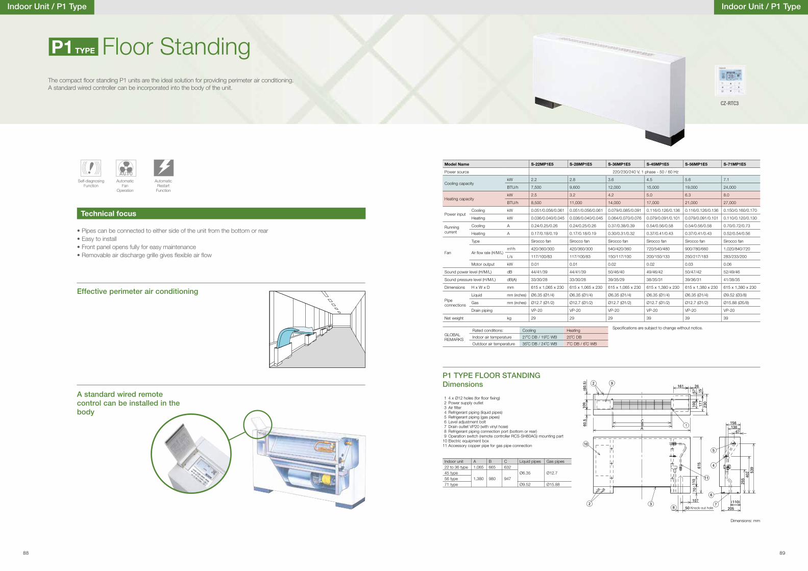
Indoor Unit / P1 Type
• Pipes can be connected to either side of the unit from the bottom or rear• Easy to install• Front panel opens fully for easy maintenance• Removable air discharge grille gives �exible air �ow
Effective perimeter air conditioning
A standard wired remote control can be installed in the body
Floor StandingThe compact �oor standing P1 units are the ideal solution for providing perimeter air conditioning. A standard wired controller can be incorporated into the body of the unit.
Technical focus
Self-diagnosing Function
Automatic Fan
Operation
AutomaticRestart
Function
P1 TYPE FLOOR STANDING Dimensions
Dimensions: mm
1 4 x Ø12 holes (for �oor �xing) 2 Power supply outlet 3 Air �lter 4 Refrigerant piping (liquid pipes) 5 Refrigerant piping (gas pipes) 6 Level adjustment bolt 7 Drain outlet VP20 (with vinyl hose) 8 Refrigerant piping connection port (bottom or rear) 9 Operation switch (remote controller RCS-SH80AG) mounting part 10 Electric equipment box 11 Accessory copper pipe for gas pipe connection
Knock-out hole
Indoor unit A B C Liquid pipes Gas pipes22 to 36 type 1,065 665 632
Ø6.35 Ø12.745 type1,380 980 94756 type
71 type Ø9.52 Ø15.88
P1TYPE
Indoor Unit / P1 Type
Model Name S-22MP1E5 S-28MP1E5 S-36MP1E5 S-45MP1E5 S-56MP1E5 S-71MP1E5
Power source 220/230/240 V, 1 phase - 50 / 60 Hz
Cooling capacitykW 2.2 2.8 3.6 4.5 5.6 7.1
BTU/h 7,500 9,600 12,000 15,000 19,000 24,000
Heating capacitykW 2.5 3.2 4.2 5.0 6.3 8.0
BTU/h 8,500 11,000 14,000 17,000 21,000 27,000
Power inputCooling kW 0.051/0.056/0.061 0.051/0.056/0.061 0.079/0.085/0.091 0.116/0.126/0.136 0.116/0.126/0.136 0.150/0.160/0.170
Heating kW 0.036/0.040/0.045 0.036/0.040/0.045 0.064/0.070/0.076 0.079/0.091/0.101 0.079/0.091/0.101 0.110/0.120/0.130
Running current
Cooling A 0.24/0.25/0.26 0.24/0.25/0.26 0.37/0.38/0.39 0.54/0.56/0.58 0.54/0.56/0.58 0.70/0.72/0.73
Heating A 0.17/0.18/0.19 0.17/0.18/0.19 0.30/0.31/0.32 0.37/0.41/0.43 0.37/0.41/0.43 0.52/0.54/0.56
Fan
Type Sirocco fan Sirocco fan Sirocco fan Sirocco fan Sirocco fan Sirocco fan
Air �ow rate (H/M/L)m³/h 420/360/300 420/360/300 540/420/360 720/540/480 900/780/660 1,020/840/720
L/s 117/100/83 117/100/83 150/117/100 200/150/133 250/217/183 283/233/200
Motor output kW 0.01 0.01 0.02 0.02 0.03 0.06
Sound power level (H/M/L) dB 44/41/39 44/41/39 50/46/40 49/46/42 50/47/42 52/49/46
Sound pressure level (H/M/L) dB(A) 33/30/28 33/30/28 39/35/29 38/35/31 39/36/31 41/38/35
Dimensions H x W x D mm 615 x 1,065 x 230 615 x 1,065 x 230 615 x 1,065 x 230 615 x 1,380 x 230 615 x 1,380 x 230 615 x 1,380 x 230
Pipe connections
Liquid mm (inches) Ø6.35 (Ø1/4) Ø6.35 (Ø1/4) Ø6.35 (Ø1/4) Ø6.35 (Ø1/4) Ø6.35 (Ø1/4) Ø9.52 (Ø3/8)
Gas mm (inches) Ø12.7 (Ø1/2) Ø12.7 (Ø1/2) Ø12.7 (Ø1/2) Ø12.7 (Ø1/2) Ø12.7 (Ø1/2) Ø15.88 (Ø5/8)
Drain piping VP-20 VP-20 VP-20 VP-20 VP-20 VP-20
Net weight kg 29 29 29 39 39 39
Specifications are subject to change without notice.
GLOBAL REMARKS
Rated conditions: Cooling Heating
Indoor air temperature 27˚C DB / 19˚C WB 20˚C DB
Outdoor air temperature 35˚C DB / 24˚C WB 7˚C DB / 6˚C WB
CZ-RTC3
88 89
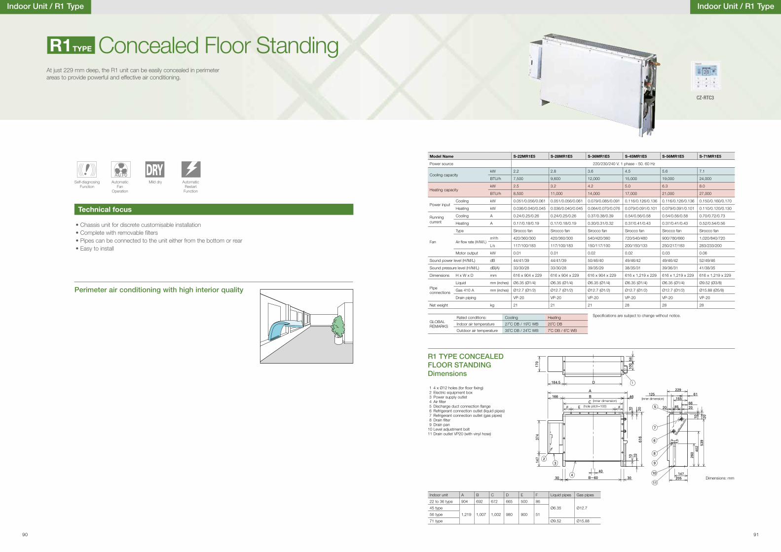
Indoor Unit / R1 Type
Perimeter air conditioning with high interior quality
• Chassis unit for discrete customisable installation• Complete with removable �lters• Pipes can be connected to the unit either from the bottom or rear• Easy to install
Concealed Floor StandingAt just 229 mm deep, the R1 unit can be easily concealed in perimeter areas to provide powerful and effective air conditioning.
Technical focus
Self-diagnosing Function
Automatic Fan
Operation
Mild dry AutomaticRestart
Function
R1 TYPE CONCEALED FLOOR STANDING Dimensions
Dimensions: mm
1 4 x Ø12 holes (for �oor �xing) 2 Electric equipment box 3 Power supply outlet 4 Air �lter 5 Discharge duct connection �ange 6 Refrigerant connection outlet (liquid pipes) 7 Refrigerant connection outlet (gas pipes) 8 Drain �lter 9 Drain pan 10 Level adjustment bolt 11 Drain outlet VP20 (with vinyl hose)
(inner dimension)(inner dimension)
(hole pitch=100)
Indoor unit A B C D E F Liquid pipes Gas pipes
22 to 36 type 904 692 672 665 500 86
Ø6.35 Ø12.745 type
1,219 1,007 1,002 980 900 5156 type
71 type Ø9.52 Ø15.88
R1TYPE
Indoor Unit / R1 Type
Model Name S-22MR1E5 S-28MR1E5 S-36MR1E5 S-45MR1E5 S-56MR1E5 S-71MR1E5
Power source 220/230/240 V. 1 phase - 50. 60 Hz
Cooling capacitykW 2.2 2.8 3.6 4.5 5.6 7.1
BTU/h 7,500 9,600 12,000 15,000 19,000 24,000
Heating capacitykW 2.5 3.2 4.2 5.0 6.3 8.0
BTU/h 8,500 11,000 14,000 17,000 21,000 27,000
Power inputCooling kW 0.051/0.056/0.061 0.051/0.056/0.061 0.079/0.085/0.091 0.116/0.126/0.136 0.116/0.126/0.136 0.150/0.160/0.170
Heating kW 0.036/0.040/0.045 0.036/0.040/0.045 0.064/0.070/0.076 0.079/0.091/0.101 0.079/0.091/0.101 0.110/0.120/0.130
Running current
Cooling A 0.24/0.25/0.26 0.24/0.25/0.26 0.37/0.38/0.39 0.54/0.56/0.58 0.54/0.56/0.58 0.70/0.72/0.73
Heating A 0.17/0.18/0.19 0.17/0.18/0.19 0.30/0.31/0.32 0.37/0.41/0.43 0.37/0.41/0.43 0.52/0.54/0.56
Fan
Type Sirocco fan Sirocco fan Sirocco fan Sirocco fan Sirocco fan Sirocco fan
Air �ow rate (H/M/L) m³/h 420/360/300 420/360/300 540/420/360 720/540/480 900/780/660 1,020/840/720
L/s 117/100/183 117/100/183 150/117/100 200/150/133 250/217/183 283/233/200
Motor output kW 0.01 0.01 0.02 0.02 0.03 0.06
Sound power level (H/M/L) dB 44/41/39 44/41/39 50/46/40 49/46/42 49/46/42 52/49/46
Sound pressure level (H/M/L) dB(A) 33/30/28 33/30/28 39/35/29 38/35/31 39/36/31 41/38/35
Dimensions H x W x D mm 616 x 904 x 229 616 x 904 x 229 616 x 904 x 229 616 x 1,219 x 229 616 x 1,219 x 229 616 x 1,219 x 229
Pipe connections
Liquid mm (inches) Ø6.35 (Ø1/4) Ø6.35 (Ø1/4) Ø6.35 (Ø1/4) Ø6.35 (Ø1/4) Ø6.35 (Ø1/4) Ø9.52 (Ø3/8)
Gas 410 A mm (inches) Ø12.7 (Ø1/2) Ø12.7 (Ø1/2) Ø12.7 (Ø1/2) Ø12.7 (Ø1/2) Ø12.7 (Ø1/2) Ø15.88 (Ø5/8)
Drain piping VP-20 VP-20 VP-20 VP-20 VP-20 VP-20
Net weight kg 21 21 21 28 28 28
Speci�cations are subject to change without notice.
GLOBAL REMARKS
Rated conditions: Cooling Heating
Indoor air temperature 27˚C DB / 19˚C WB 20˚C DB
Outdoor air temperature 35˚C DB / 24˚C WB 7˚C DB / 6˚C WB
CZ-RTC3
90 91
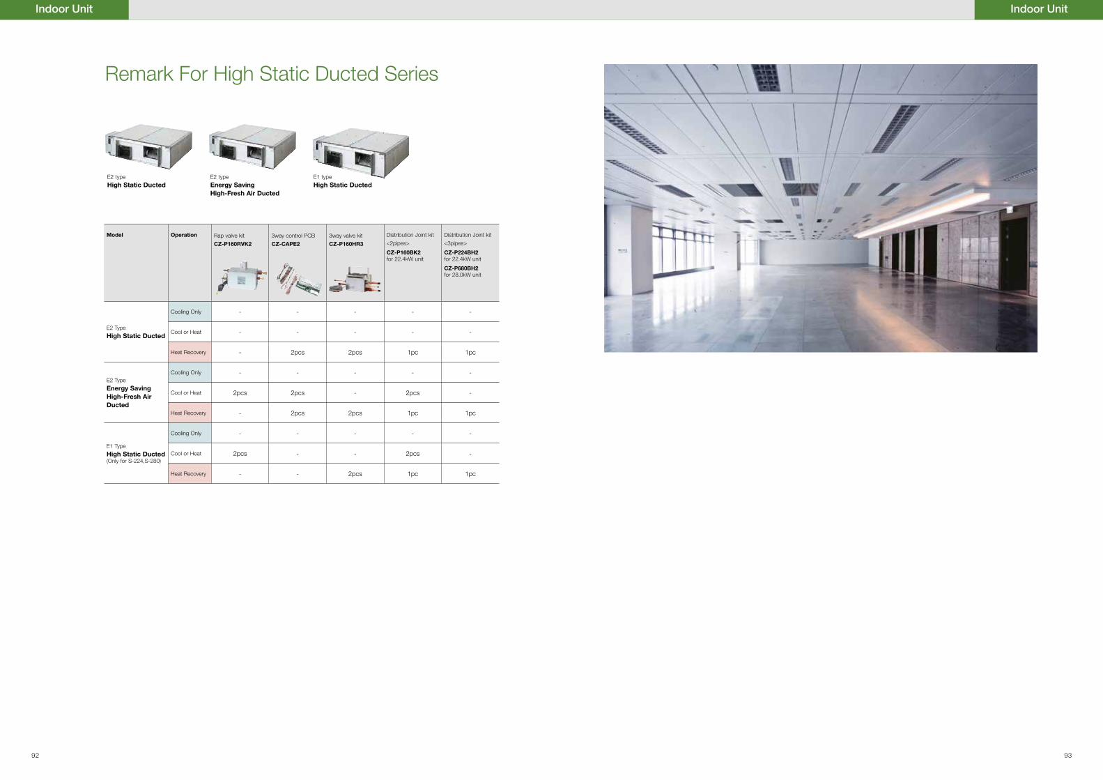
Model Operation Rap valve kit
CZ-P160RVK2
3way control PCB CZ-CAPE2
3way valve kit
CZ-P160HR3
Distribution Joint kit
<2pipes>
CZ-P160BK2for 22.4kW unit
Distribution Joint kit
<3pipes>
CZ-P224BH2for 22.4kW unit
CZ-P680BH2for 28.0kW unit
E2 Type
High Static Ducted
Cooling Only - - - - -
Cool or Heat - - - - -
Heat Recovery - 2pcs 2pcs 1pc 1pc
E2 Type
Energy Saving High-Fresh Air Ducted
Cooling Only - - - - -
Cool or Heat 2pcs 2pcs - 2pcs -
Heat Recovery - 2pcs 2pcs 1pc 1pc
E1 Type
High Static Ducted(Only for S-224,S-280)
Cooling Only - - - - -
Cool or Heat 2pcs - - 2pcs -
Heat Recovery - - 2pcs 1pc 1pc
E2 type
High Static DuctedE2 type
Energy Saving High-Fresh Air Ducted
E1 type
High Static Ducted
Indoor UnitIndoor Unit
Remark For High Static Ducted Series
92 93
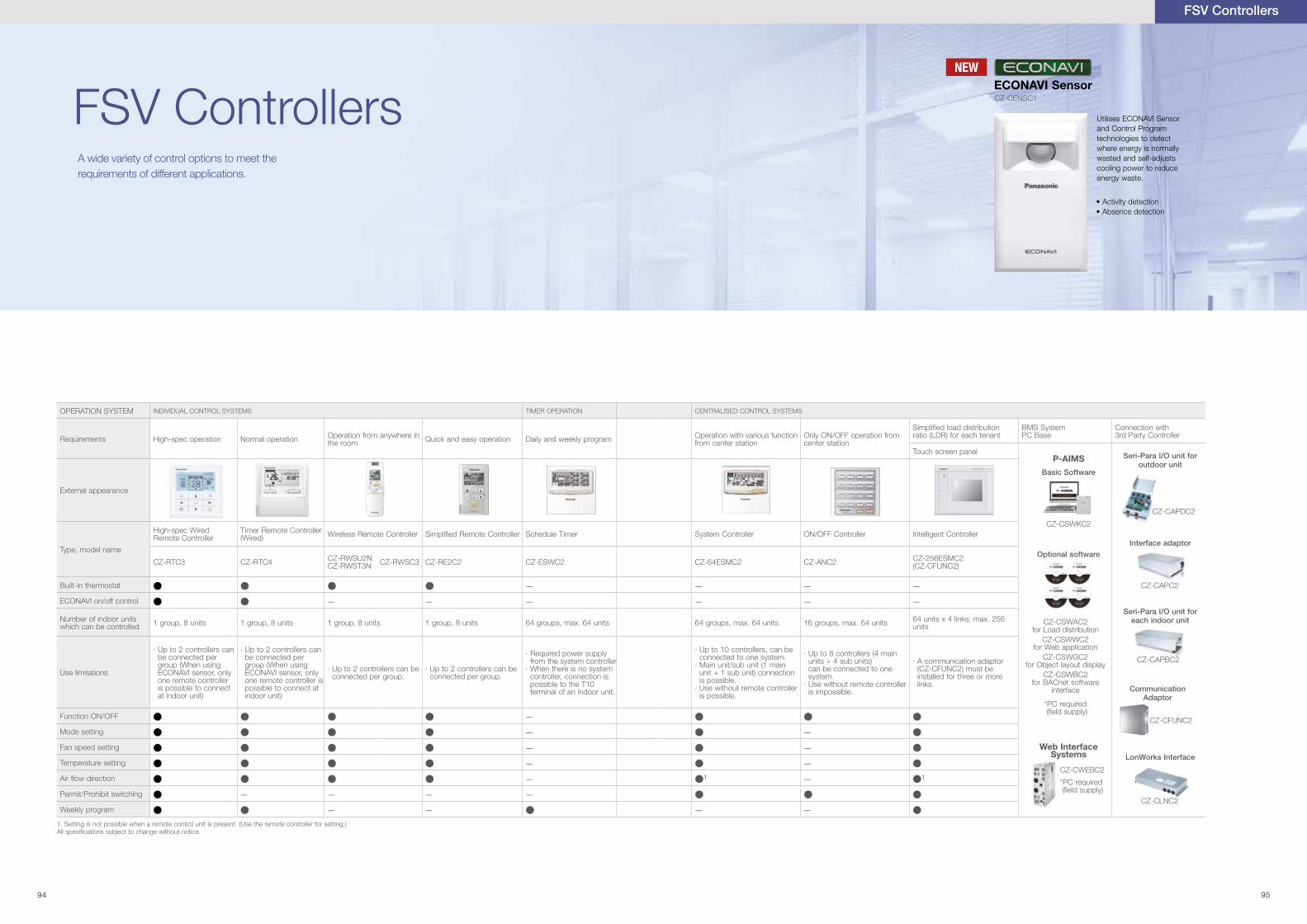
FSV ControllersA wide variety of control options to meet the requirements of different applications.
FSV Controllers
NEW
CZ-CENSC1
ECONAVI Sensor
Utilises ECONAVI Sensor and Control Program technologies to detect where energy is normally wasted and self-adjusts cooling power to reduce energy waste.
• Activity detection• Absence detection
94 95
OPERATION SYSTEM INDIVIDUAL CONTROL SYSTEMS TIMER OPERATION CENTRALISED CONTROL SYSTEMS
Requirements High-spec operation Normal operation Operation from anywhere in the room Quick and easy operation Daily and weekly program Operation with various function
from center stationOnly ON/OFF operation from center station
Simpli�ed load distribution ratio (LDR) for each tenant
BMS SystemPC Base
Connection with3rd Party Controller
Touch screen panel
External appearance
Type, model name
High-spec WiredRemote Controller
Timer Remote Controller (Wired) Wireless Remote Controller Simpli�ed Remote Controller Schedule Timer System Controller ON/OFF Controller Intelligent Controller
CZ-RTC3 CZ-RTC4 CZ-RWSU2N CZ-RWST3N CZ-RWSC3 CZ-RE2C2 CZ-ESWC2 CZ-64ESMC2 CZ-ANC2 CZ-256ESMC2
(CZ-CFUNC2)
Built-in thermostat ● ● ● ● — — — —ECONAVI on/off control ● ● — — — — — —
Number of indoor units which can be controlled 1 group, 8 units 1 group, 8 units 1 group, 8 units 1 group, 8 units 64 groups, max. 64 units 64 groups, max. 64 units 16 groups, max. 64 units 64 units x 4 links, max. 256
units
Use limitations
nac srellortnoc 2 ot pU ·be connected per group (When using ECONAVI sensor, only one remote controller is possible to connect at indoor unit)
nac srellortnoc 2 ot pU ·be connected per group (When using ECONAVI sensor, only one remote controller is possible to connect at indoor unit)
eb nac srellortnoc 2 ot pU ·connected per group.
eb nac srellortnoc 2 ot pU ·connected per group.
ylppus rewop deriuqeR ·from the system controller
metsys on si ereht nehW ·controller, connection is possible to the T10terminal of an indoor unit.
eb nac ,srellortnoc 01 ot pU ·connected to one system.
niam 1( tinu bus/tinu niaM ·unit + 1 sub unit) connection is possible.
rellortnoc etomer tuohtiw esU ·is possible.
niam 4( srellortnoc 8 ot pU ·units + 4 sub units)can be connected to one system.
rellortnoc etomer tuohtiw esU ·is impossible.
rotpada noitacinummoc A ·(CZ-CFUNC2) must be installed for three or more links.
Function ON/OFF ● ● ● ● — ● ● ●
Mode setting ● ● ● ● — ● — ●
Fan speed setting ● ● ● ● — ● — ●
Temperature setting ● ● ● ● — ● — ●
Air �ow direction ● ● ● ● — ●¹ — ●¹Permit/Prohibit switching ● — — — — ● ● ●
Weekly program ● ● — — ● — — ●
Interface adaptor
Seri-Para I/O unit for each indoor unit
Communication Adaptor
Web Interface Systems
Optional software
CZ-CSWKC2
CZ-CWEBC2
*PC required (�eld supply)
*PC required (�eld supply)
CZ-CSWAC2 for Load distribution
CZ-CSWWC2 for Web application
CZ-CSWGC2 for Object layout display
CZ-CSWBC2 for BACnet software
interface
CZ-CAPDC2
LonWorks Interface
CZ-CAPC2
CZ-CAPBC2
CZ-CFUNC2
CZ-CLNC2
Seri-Para I/O unit for outdoor unit
P-AIMS
Basic Software
1. Setting is not possible when a remote control unit is present. (Use the remote controller for setting.)All speci�cations subject to change without notice.
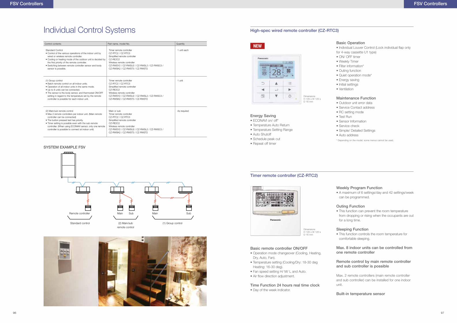
Control contents Part name, model No. Quantity
Standard Control• Control of the various operations of the indoor unit by
wired or wireless remote controller.• Cooling or heating mode of the outdoor unit is decided by
the �rst priority of the remote controller.• Switching between remote controller sensor and body
sensor is possible.
Timer remote controllerCZ-RTC2 / CZ-RTC3Simpli�ed remote controllerCZ-RE2C2Wireless remote controllerCZ-RWSY2 / CZ-RWSU2 / CZ-RWSL2 / CZ-RWSC3 / CZ-RWSK2 / CZ-RWST3 / CZ-RWST2
1 unit each
(1) Group control• Batch remote control on all indoor units.• Operation of all indoor units in the same mode.• Up to 8 units can be connected.• The sensor is the body sensor, and thermostat ON/OFF
setting in regard to the temperature set by the remote controller is possible for each indoor unit.
Timer remote controllerCZ-RTC2 / CZ-RTC3Simpli�ed remote controllerCZ-RE2C2Wireless remote controllerCZ-RWSY2 / CZ-RWSU2 / CZ-RWSL2 / CZ-RWSC3 / CZ-RWSK2 / CZ-RWST3 / CZ-RWST2
1 unit
(2) Main/sub remote control• Max 2 remote controllers per indoor unit. (Main remote
controller can be connected)• The button pressed last has priority.• Timer setting is possible even with the sub remote
controller. (When using ECONAVI sensor, only one remote controller is possible to connect at indoor unit)
Main or subTimer remote controllerCZ-RTC2 / CZ-RTC3Simpli�ed remote controllerCZ-RE2C2Wireless remote controllerCZ-RWSY2 / CZ-RWSU2 / CZ-RWSL2 / CZ-RWSC3 / CZ-RWSK2 / CZ-RWST3 / CZ-RWST2
As required
Individual Control Systems
SYSTEM EXAMPLE FSV
Standard control (2) Main/sub
remote control
(1) Group control
High-spec wired remote controller (CZ-RTC3)
Timer remote controller (CZ-RTC2)
Basic Operation• Individual Louver Control (Lock individual �ap only for 4-way cassette U1 type)• ON/ OFF timer• Weekly Timer• Filter information*• Outing function• Quiet operation mode*• Energy saving• Initial settings• Ventilation
Maintenance Function• Outdoor unit error data• Service Contact address• RC setting mode• Test Run• Sensor Information• Service check• Simple/ Detailed Settings• Auto address
Energy Saving• ECONAVI on/ off*• Temperature Auto Return• Temperature Setting Range• Auto Shutoff• Schedule peak cut• Repeat off timer
Basic remote controller ON/OFF• Operation mode changeover (Cooling, Heating,
Dry, Auto, Fan).• Temperature setting (Cooling/Dry: 18-30 deg
Heating: 16-30 deg).• Fan speed setting H/ M/ L and Auto.• Air �ow direction adjustment.
Time Function 24 hours real time clock• Day of the week indicator.
Weekly Program Function• A maximum of 6 settings/day and 42 settings/week
can be programmed.
Outing Function• This function can prevent the room temperature
from dropping or rising when the occupants are out for a long time.
Sleeping Function• This function controls the room temperature for
comfortable sleeping.
Max. 8 indoor units can be controlled from one remote controller
Remote control by main remote controller and sub controller is possible
Max. 2 remote controllers (main remote controller and sub controller) can be installed for one indoor unit.
Built-in temperature sensor
DimensionsH 120 x W 120 x D 16 mm
* Depending on the model, some menus cannot be used.
DimensionsH 120 x W 120 x D 16 mm
FSV ControllersFSV Controllers
Remote controller Main MainSub Sub
NEW
96 97
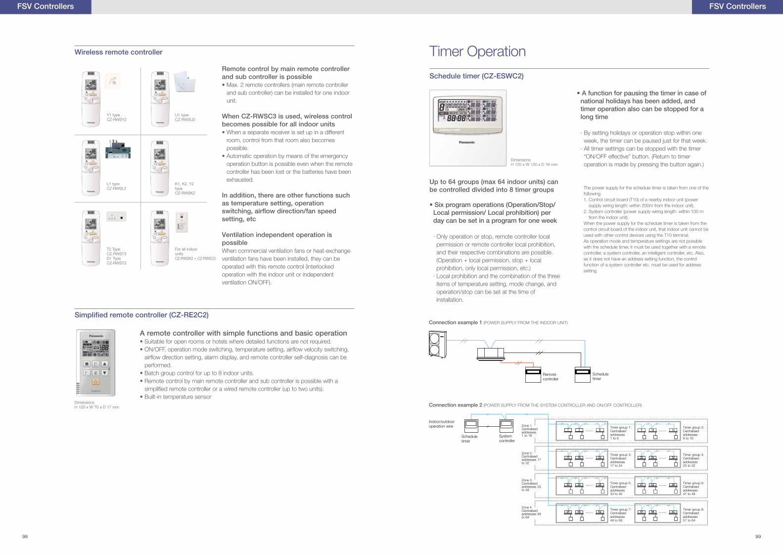
Timer Operation
Schedule timer (CZ-ESWC2)
• Six program operations (Operation/Stop/Local permission/ Local prohibition) per day can be set in a program for one week
· Only operation or stop, remote controller local permission or remote controller local prohibition, and their respective combinations are possible. (Operation + local permission, stop + local prohibition, only local permission, etc.)
· Local prohibition and the combination of the three items of temperature setting, mode change, and operation/stop can be set at the time of installation.
Up to 64 groups (max 64 indoor units) can be controlled divided into 8 timer groups
• A function for pausing the timer in case of national holidays has been added, and timer operation also can be stopped for a long time
· By setting holidays or operation stop within one week, the timer can be paused just for that week.
· All timer settings can be stopped with the timer “ON/OFF effective” button. (Return to timer operation is made by pressing the button again.)
The power supply for the schedule timer is taken from one of the following.1. Control circuit board (T10) of a nearby indoor unit (power
supply wiring length: within 200m from the indoor unit).2. System controller (power supply wiring length: within 100 m
from the indoor unit).When the power supply for the schedule timer is taken from the control circuit board of the indoor unit, that indoor unit cannot be used with other control devices using the T10 terminal.As operation mode and temperature settings are not possible with the schedule timer, it must be used together with a remote controller, a system controller, an intelligent controller, etc. Also, as it does not have an address setting function, the control function of a system controller etc. must be used for address setting.
DimensionsH 120 x W 120 x D 16 mm
FSV Controllers
Connection example 1 (POWER SUPPLY FROM THE INDOOR UNIT)
Connection example 2 (POWER SUPPLY FROM THE SYSTEM CONTROLLER AND ON/OFF CONTROLLER)
Remote controller
Schedule timer
Schedule timer
Timer group 1: Centralised addresses 1 to 8
Timer group 3: Centralised addresses 17 to 24
Timer group 5: Centralised addresses 33 to 40
Timer group 7: Centralised addresses 49 to 56
Timer group 2: Centralised addresses 9 to 16
Timer group 4: Centralised addresses 25 to 32
Timer group 6: Centralised addresses 41 to 48
Timer group 8: Centralised addresses 57 to 64
System controller
Indoor/outdoor operation wire Zone 1
Centralised addresses 1 to 16
Zone 2Centralised addresses 17 to 32
Zone 3Centralised addresses 33 to 48
Zone 4Centralised addresses 49 to 64
FSV Controllers
Wireless remote controller
A remote controller with simple functions and basic operation• Suitable for open rooms or hotels where detailed functions are not required.• ON/OFF, operation mode switching, temperature setting, air�ow velocity switching,
air�ow direction setting, alarm display, and remote controller self-diagnosis can be performed.
• Batch group control for up to 8 indoor units.• Remote control by main remote controller and sub controller is possible with a
simpli�ed remote controller or a wired remote controller (up to two units).• Built-in temperature sensor
Remote control by main remote controller and sub controller is possible• Max. 2 remote controllers (main remote controller
and sub controller) can be installed for one indoor unit.
When CZ-RWSC3 is used, wireless control becomes possible for all indoor units• When a separate receiver is set up in a different
room, control from that room also becomes possible.
• Automatic operation by means of the emergency operation button is possible even when the remote controller has been lost or the batteries have been exhausted.
In addition, there are other functions such as temperature setting, operation switching, air�ow direction/fan speed setting, etc
Ventilation independent operation is possibleWhen commercial ventilation fans or heat-exchange ventilation fans have been installed, they can be operated with this remote control (interlocked operation with the indoor unit or independent ventilation ON/OFF).
DimensionsH 120 x W 70 x D 17 mm
Y1 typeCZ-RWSY2
U1 typeCZ-RWSU2
K1, K2, Y2 typeCZ-RWSK2
L1 typeCZ-RWSL2
T2 TypeCZ-RWST3D1 TypeCZ-RWST2
For all indoor unitsCZ-RWSK2 + CZ-RWSC3
98 99
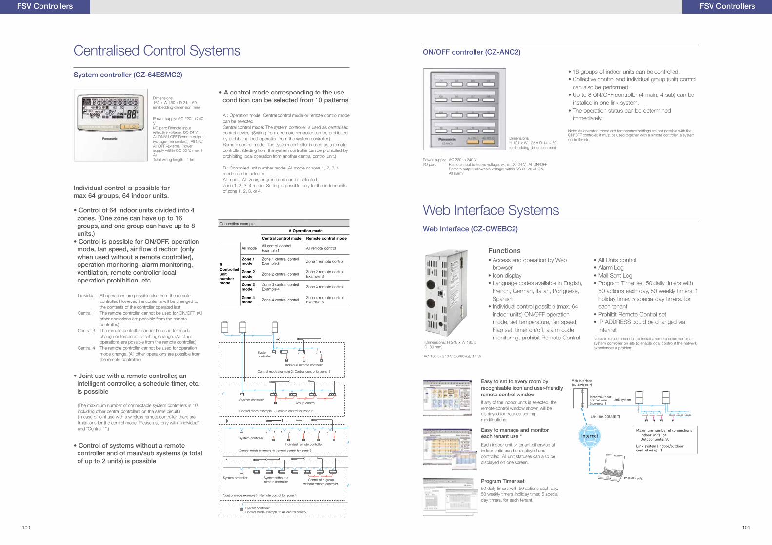
ON/OFF controller (CZ-ANC2)
Web Interface SystemsWeb Interface (CZ-CWEBC2)
Functions
Power supply: AC 220 to 240 VI/O part: Remote input (effective voltage: within DC 24 V): All ON/OFF Remote output (allowable voltage: within DC 30 V): All ON, All alarm
• 16 groups of indoor units can be controlled.• Collective control and individual group (unit) control
can also be performed.• Up to 8 ON/OFF controller (4 main, 4 sub) can be
installed in one link system.• The operation status can be determined
immediately.
Note: As operation mode and temperature settings are not possible with the ON/OFF controller, it must be used together with a remote controller, a system controller etc.
• Access and operation by Web browser
• Icon display• Language codes available in English,
French, German, Italian, Portguese, Spanish
• Individual control possible (max. 64 indoor units) ON/OFF operation mode, set temperature, fan speed, Flap set, timer on/off, alarm code monitoring, prohibit Remote Control
• All Units control• Alarm Log• Mail Sent Log• Program Timer set 50 daily timers with
50 actions each day, 50 weekly timers, 1 holiday timer, 5 special day timers, for each tenant
• Prohibit Remote Control set• IP ADDRESS could be changed via
InternetNote: It is recommended to install a remote controller or a system controller on site to enable local control if the network experiences a problem.
(Dimensions: H 248 x W 185 x D 80 mm)
AC 100 to 240 V (50/60Hz), 17 W
DimensionsH 121 x W 122 x D 14 + 52(embedding dimension mm)
Web Interface(CZ-CWEBC2)
Indoor/outdoorcontrol wire(non-polar)
Link system
Maximum number of connections:
Outdoor units: 30Indoor units: 64
Link system (Indoor/outdoor control wire) : 1
PC (field supply)
LAN (10/100BASE-T)
Internet
Easy to set to every room by recognisable icon and user-friendly remote control window
Easy to manage and monitor each tenant use *
Program Timer set
If any of the indoor units is selected, the remote control window shown will be displayed for detailed setting modi�cations.
Each indoor unit or tenant otherwise all indoor units can be displayed and controlled. All unit statuses can also be displayed on one screen.
50 daily timers with 50 actions each day, 50 weekly timers, holiday timer, 5 special day timers, for each tenant.
FSV ControllersFSV Controllers
Centralised Control Systems
System controller (CZ-64ESMC2)
Individual control is possible for max 64 groups, 64 indoor units.
• Joint use with a remote controller, an intelligent controller, a schedule timer, etc. is possible
• Control of 64 indoor units divided into 4 zones. (One zone can have up to 16 groups, and one group can have up to 8 units.)
• Control is possible for ON/OFF, operation mode, fan speed, air �ow direction (only when used without a remote controller), operation monitoring, alarm monitoring, ventilation, remote controller local operation prohibition, etc.
(The maximum number of connectable system controllers is 10, including other central controllers on the same circuit.)(In case of joint use with a wireless remote controller, there are limitations for the control mode. Please use only with “Individual” and “Central 1”.)
• Control of systems without a remote controller and of main/sub systems (a total of up to 2 units) is possible
Individual All operations are possible also from the remote controller. However, the contents will be changed to the contents of the controller operated last.
Central 1 The remote controller cannot be used for ON/OFF. (All other operations are possible from the remote controller.)
Central 3 The remote controller cannot be used for mode change or temperature setting change. (All other operations are possible from the remote controller.)
Central 4 The remote controller cannot be used for operation mode change. (All other operations are possible from the remote controller.)
Power supply: AC 220 to 240 VI/O part: Remote input (effective voltage: DC 24 V): All ON/All OFF Remote output (voltage-free contact): All ON/All OFF (external Power supply within DC 30 V, max 1 A)Total wiring length : 1 km
• A control mode corresponding to the use condition can be selected from 10 patterns
A : Operation mode: Central control mode or remote control mode can be selectedCentral control mode: The system controller is used as centralised control device. (Setting from a remote controller can be prohibited by prohibiting local operation from the system controller.)Remote control mode: The system controller is used as a remote controller. (Setting from the system controller can be prohibited by prohibiting local operation from another central control unit.)
B : Controlled unit number mode: All mode or zone 1, 2, 3, 4 mode can be selectedAll mode: All, zone, or group unit can be selected.Zone 1, 2, 3, 4 mode: Setting is possible only for the indoor units of zone 1, 2, 3, or 4.
Connection example
A Operation mode
Central control mode Remote control mode
BControlled unit numbermode
All mode All central controlExample 1 All remote control
Zone 1 mode
Zone 1 central controlExample 2 Zone 1 remote control
Zone 2 mode Zone 2 central control Zone 2 remote control
Example 3
Zone 3 mode
Zone 3 central controlExample 4 Zone 3 remote control
Zone 4 mode Zone 4 central control Zone 4 remote control
Example 5
Dimensions160 x W 160 x D 21 + 69(embedding dimension mm)
Control mode example 2: Central control for zone 1
System controller
Individual remote controller
Individual remote controller
Control of a group without remote controller
Group controlSystem controller
System controller
System controller
System controllerControl mode example 1: All central control
System without a remote controller
Control mode example 3: Remote control for zone 2
Control mode example 4: Central control for zone 3
Control mode example 5: Remote control for zone 4
100 101
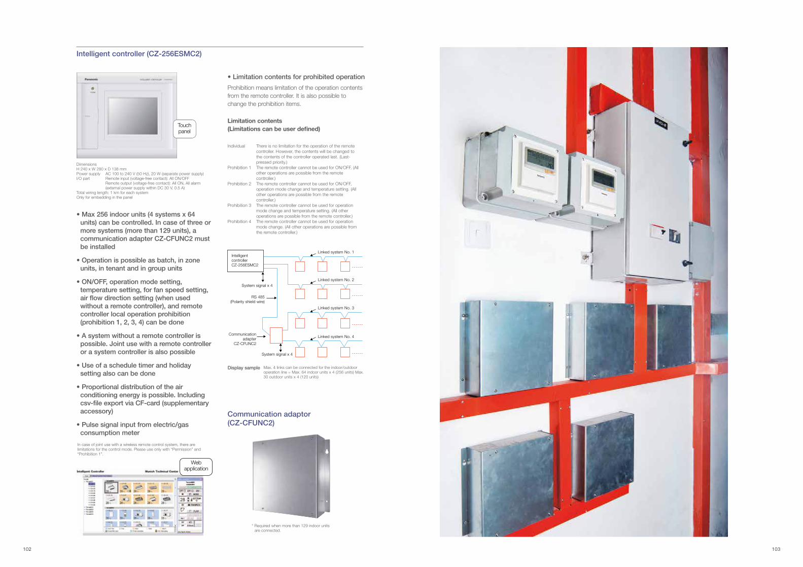
Intelligent controller (CZ-256ESMC2)
• Max 256 indoor units (4 systems x 64 units) can be controlled. In case of three or more systems (more than 129 units), a communication adapter CZ-CFUNC2 must be installed
• Operation is possible as batch, in zone units, in tenant and in group units
• ON/OFF, operation mode setting, temperature setting, for fan speed setting, air �ow direction setting (when used without a remote controller), and remote controller local operation prohibition (prohibition 1, 2, 3, 4) can be done
• A system without a remote controller is possible. Joint use with a remote controller or a system controller is also possible
• Use of a schedule timer and holiday setting also can be done
• Proportional distribution of the air conditioning energy is possible. Including csv-�le export via CF-card (supplementary accessory)
• Pulse signal input from electric/gas consumption meter
In case of joint use with a wireless remote control system, there are limitations for the control mode. Please use only with “Permission” and “Prohibition 1”.
Prohibition means limitation of the operation contents from the remote controller. It is also possible to change the prohibition items.
Limitation contents (Limitations can be user de�ned)
Individual There is no limitation for the operation of the remote controller. However, the contents will be changed to the contents of the controller operated last. (Last-pressed priority.)
Prohibition 1 The remote controller cannot be used for ON/OFF. (All other operations are possible from the remote controller.)
Prohibition 2 The remote controller cannot be used for ON/OFF, operation mode change and temperature setting. (All other operations are possible from the remote controller.)
Prohibition 3 The remote controller cannot be used for operation mode change and temperature setting. (All other operations are possible from the remote controller.)
Prohibition 4 The remote controller cannot be used for operation mode change. (All other operations are possible from the remote controller.)
Intelligent controller CZ-256ESMC2
System signal x 4
System signal x 4
Linked system No. 1
Linked system No. 2
Linked system No. 3
Linked system No. 4
RS 485(Polarity shield wire)
Communication adapter
CZ-CFUNC2
DimensionsH 240 x W 280 x D 138 mmPower supply AC 100 to 240 V (50 Hz), 20 W (separate power supply)I/O part Remote input (voltage-free contact): All ON/OFF Remote output (voltage-free contact): All ON, All alarm (external power supply within DC 30 V, 0.5 A)Total wiring length: 1 km for each systemOnly for embedding in the panel
Touchpanel
Webapplication
Display sample Max. 4 links can be connected for the indoor/outdoor operation line = Max. 64 indoor units x 4 (256 units) Max. 30 outdoor units x 4 (120 units)
• Limitation contents for prohibited operation
Communication adaptor (CZ-CFUNC2)
* Required when more than 129 indoor units are connected.
102 103

User PCUSB line
Converter for each links(Field supply)
RS485 (Polarised) Building A
Building B
Building D
Communication Adaptor
Panasonic total air conditioning management system
P-AIMS Basic software / CZ-CSWKC2
Up to 1024 indoor units can be controlled by one PC
Functions of basic software
P-AIMS optional softwareCZ-CSWAC2 for Load distribution
Load distribution calculation for each tenant
Whole system can be controlled visually
Connectable to BMS system
Web access & control from remote station
P-AIMS optional softwareCZ-CSWGC2 for Object layout display
P-AIMS optional softwareCZ-CSWWC2 for Web application
P-AIMS optional softwareCZ-CSWBC2 for BACnet software interface
• Standard remote control for all indoor units• Many timer schedule programs can be set on the calender• Detailed information display for alarms• CSV file output with alarm history, operating status.• Automatic data backup to HDD
• Air-conditioner load distribution ratio is calculated for each unit (tenant) with used energy consumption data (m3, kWh).
• Calculated data is stored with CSV type file.• Data of last 365 days is stored
• Operating status monitor is available on the layout display.• Object’s layout and indoor unit’s location can be checked at once.• Each unit can be controlled by virtual remote controller on the display.• Max 4 layout screens are shown at once.
• Accessing P-AIMS software from remote PC.• You can monitor/operate FSV systems by using Web
browser (Internet Explorer).
• Can communicate with other equipment by BACnet protocol.• FSV systems can be controlled by both BMS and P-AIMS.• Max 255 indoor units can be connected to 1 PC (that has
P-AIMS basic & BACnet software).
P-AIMS
The P-AIMS is ideal for large areas/buildings such as shopping centers, universities and of�ce buildings. Up to eight Communication Adaptors (C/A) can be connected to a P-AIMS to enable control of 1024 indoor units with one “P-AIMS” PC.
FSV Controllers
With 4 upgrade packages the basic software can be upgraded to suit individual requirements
CZ-CFUNC2
Minimum PC requirements:Windows 7 Professional (32bit) or Windows XP Professional (32bit)CPU: Intel Core™ i3-2100 processor or higherMemory: 2GB or overHDD: 100GB or over
• Wiring length (PC~C/A) Max. 1 km Max. 8 C/A for 1 system• Wiring length for each link from C/A Max. 1 km
FSV Controllers
104 105
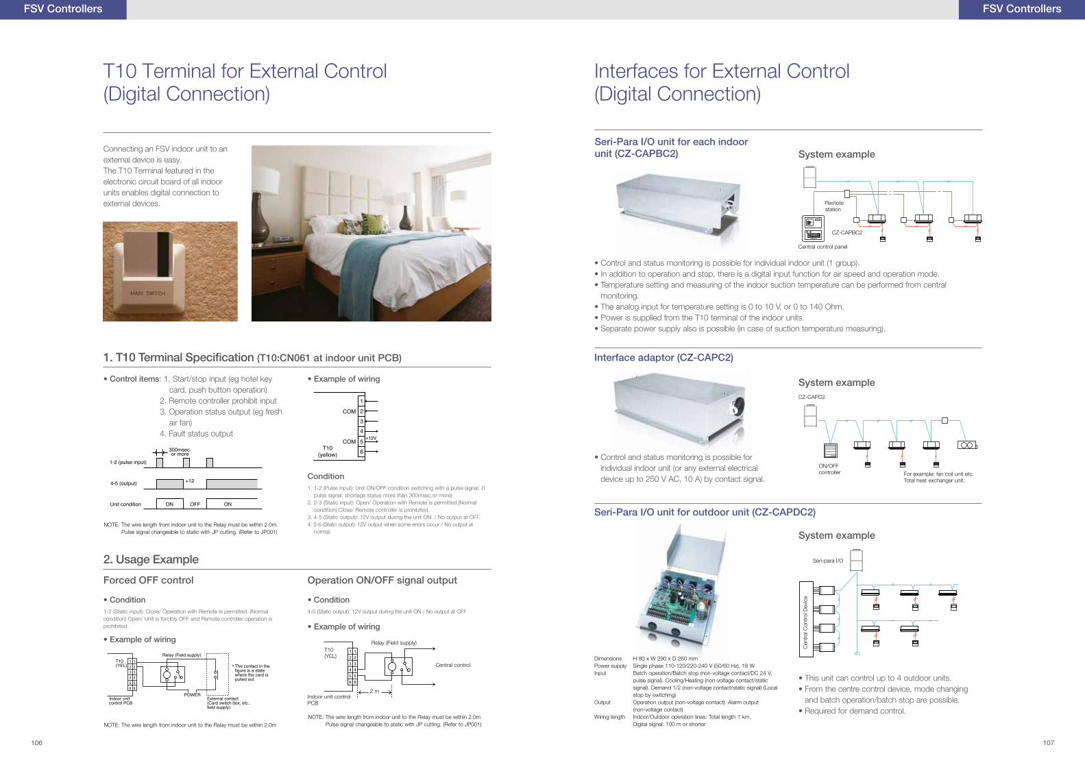
FSV Controllers
T10 Terminal for External Control (Digital Connection)
Connecting an FSV indoor unit to an external device is easy. The T10 Terminal featured in the electronic circuit board of all indoor units enables digital connection to external devices.
Seri-Para I/O unit for outdoor unit (CZ-CAPDC2)
Dimensions H 80 x W 290 x D 260 mmPower supply Single phase 110-120/220-240 V (50/60 Hz), 18 WInput Batch operation/Batch stop (non-voltage contact/DC 24 V,
pulse signal). Cooling/Heating (non-voltage contact/static signal). Demand 1/2 (non-voltage contact/static signal) (Local stop by switching)
Output Operation output (non-voltage contact). Alarm output (non-voltage contact)Wiring length Indoor/Outdoor operation lines: Total length 1 km. Digital signal: 100 m or shorter
• This unit can control up to 4 outdoor units.• From the centre control device, mode changing
and batch operation/batch stop are possible.• Required for demand control.
Seri-para I/O
Cen
tral
Con
trol
Dev
ice
System example
Interfaces for External Control (Digital Connection)
Interface adaptor (CZ-CAPC2)
CZ-CAPC2
ON/OFF controller For example: fan coil unit etc.
Total heat exchanger unit.
• Control and status monitoring is possible for individual indoor unit (or any external electrical device up to 250 V AC, 10 A) by contact signal.
Seri-Para I/O unit for each indoor unit (CZ-CAPBC2)
• Control and status monitoring is possible for individual indoor unit (1 group).• In addition to operation and stop, there is a digital input function for air speed and operation mode.• Temperature setting and measuring of the indoor suction temperature can be performed from central
monitoring.• The analog input for temperature setting is 0 to 10 V, or 0 to 140 Ohm.• Power is supplied from the T10 terminal of the indoor units.• Separate power supply also is possible (in case of suction temperature measuring).
System example
System example
Remote station
Central control panel
CZ-CAPBC2
NOTE: The wire length from indoor unit to the Relay must be within 2.0m. Pulse signal changeable to static with JP cutting. (Refer to JP001)
NOTE: The wire length from indoor unit to the Relay must be within 2.0m
Central control
• Example of wiring
• Example of wiring
4-5 (Static output): 12V output during the unit ON / No output at OFF
1. 1-2 (Pulse input): Unit ON/OFF condition switching with a pulse signal. (1 pulse signal: shortage status more than 300msec.or more)
2. 2-3 (Static input): Open/ Operation with Remote is permitted.(Normal condition) Close/ Remote controller is prohibited.
3. 4-5 (Static output): 12V output during the unit ON. / No output at OFF.4. 5-6 (Static output): 12V output when some errors occur / No output at
normal.
1-2 (Static input): Close/ Operation with Remote is permitted. (Normal condition) Open/ Unit is forcibly OFF and Remote controller operation is prohibited.
• Control items: 1. Start/stop input (eg hotel key card, push button operation)
2. Remote controller prohibit input 3. Operation status output (eg fresh
air fan) 4. Fault status output
• Example of wiring
• Condition
Condition
• Condition
Indoor unit control PCB
1
T10(yellow)
O OFF
1
T10(yellow)
O OFF
Relay (Field supply)
The contact in thefigure is a state where the card is pulled out.
POWERExternal contact(Card switch box, etc.:field supply)
Indoor unit control PCB
T10(YEL)
2 m
T10(YEL)
(T10:CN061 at indoor unit PCB)
NOTE: The wire length from indoor unit to the Relay must be within 2.0m Pulse signal changeable to static with JP cutting. (Refer to JP001)
2. Usage Example
Forced OFF control Operation ON/OFF signal output
Relay (Field supply)
FSV Controllers
106 107
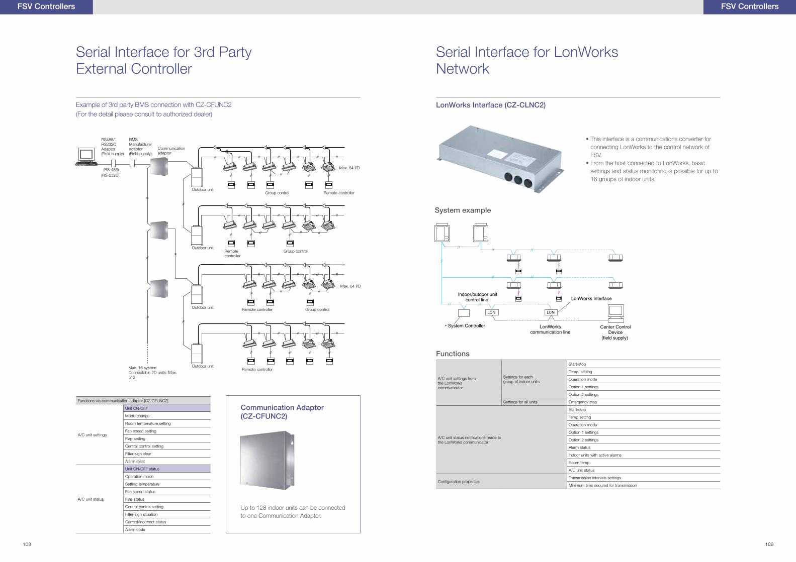
Center Control
LON LON
• System Controller
LonWorks Interface (CZ-CLNC2)
Functions
• This interface is a communications converter for connecting LonWorks to the control network of FSV.
• From the host connected to LonWorks, basic settings and status monitoring is possible for up to 16 groups of indoor units.
A/C unit settings from the LonWorks communicator
Settings for each group of indoor units
Start/stop
Temp. setting
Operation mode
Option 1 settings
Option 2 settings
Settings for all units Emergency stop
A/C unit status noti�cations made to the LonWorks communicator
Start/stop
Temp setting
Operation mode
Option 1 settings
Option 2 settings
Alarm status
Indoor units with active alarms
Room temp.
A/C unit status
Con�guration propertiesTransmission intervals settings
Minimum time secured for transmission
System example
FSV Controllers
Serial Interface for 3rd Party External Controller
Serial Interface for LonWorks Network
Example of 3rd party BMS connection with CZ-CFUNC2 (For the detail please consult to authorized dealer)
Functions via communication adaptor [CZ-CFUNC2]
A/C unit settings
Unit ON/OFF
Mode-change
Room temperature setting
Fan speed setting
Flap setting
Central control setting
Filter-sign clear
Alarm reset
A/C unit status
Unit ON/OFF status
Operation mode
Setting temperature
Fan speed status
Flap status
Central control setting
Filter-sign situation
Correct/incorrect status
Alarm code
RS485/RS232CAdaptor(Field supply)
BMS Manufactureradaptor(Field supply)
Communication adaptor
Outdoor unitGroup control Remote controller
Max. 64 I/D
Max. 64 I/D
Remote controller
Remote controller
Remote controllerMax. 16 systemConnectable I/D units: Max. 512
Group control
Group control
Outdoor unit
Outdoor unit
Outdoor unit
(RS-485)(RS-232C)
Communication Adaptor (CZ-CFUNC2)
Up to 128 indoor units can be connected to one Communication Adaptor.
FSV Controllers
108 109
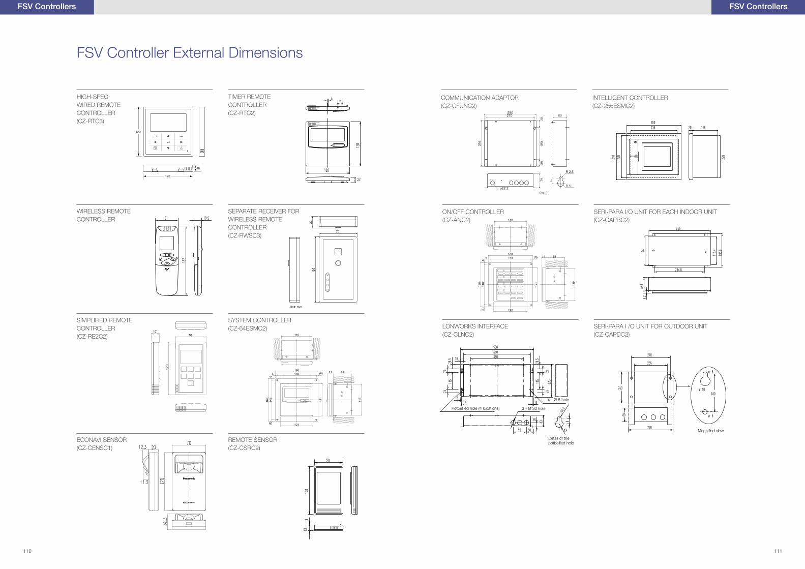
1770
120
66.8
116.
8
10
4.4
83.5
33.4
6.61
13
33.5
16.7
9.4
4.45.4
9.4
8
SIMPLIFIED REMOTE CONTROLLER(CZ-RE2C2)
FSV Controllers
FSV Controller External Dimensions
TIMER REMOTE CONTROLLER(CZ-RTC2)
1601486 (6)
121
160
148
6(6
)
121
115
6921
116
SYSTEM CONTROLLER(CZ-64ESMC2)
WIRELESS REMOTE CONTROLLER
REMOTE SENSOR(CZ-CSRC2)
(mm)
29080
ø22.2
256
270
180
3838
79 8
R 2.5
R 5
INTELLIGENT CONTROLLER(CZ-256ESMC2)
COMMUNICATION ADAPTOR(CZ-CFUNC2)
116
1601486 (6)
122
160
148
6(6
)
121
115
6914
ON/OFF CONTROLLER(CZ-ANC2)
SERI-PARA I/O UNIT FOR EACH INDOOR UNIT(CZ-CAPBC2)
LONWORKS INTERFACE(CZ-CLNC2)
SERI-PARA I /O UNIT FOR OUTDOOR UNIT(CZ-CAPDC2)
4 - Ø 5 hole
Magni�ed view
Detail of the potbellied hole
3 - Ø 30 holePotbellied hole (4 locations)
FSV Controllers
HIGH-SPECWIRED REMOTE CONTROLLER(CZ-RTC3)
120
120
16
SEPARATE RECEIVER FORWIRELESS REMOTECONTROLLER(CZ-RWSC3)
70
2012
0
Unit: mm
ECONAVI SENSOR(CZ-CENSC1)
110 111
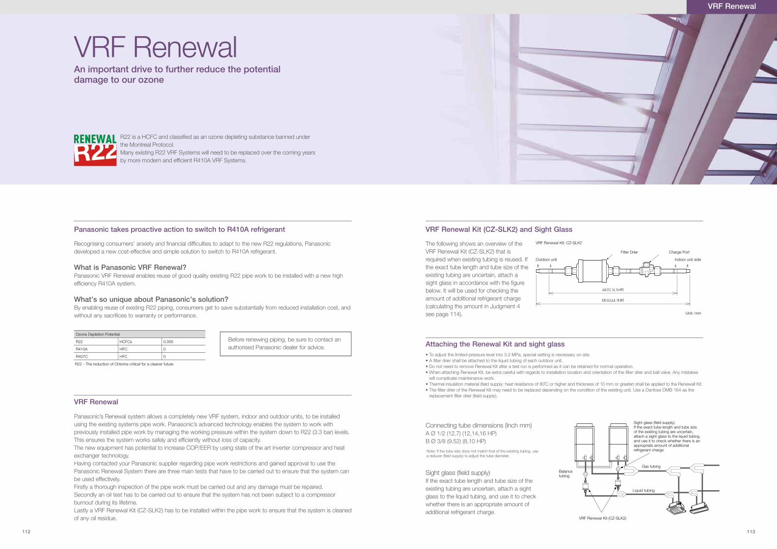
Recognising consumers’ anxiety and �nancial dif�culties to adapt to the new R22 regulations, Panasonic developed a new cost-effective and simple solution to switch to R410A refrigerant.
What is Panasonic VRF Renewal? Panasonic VRF Renewal enables reuse of good quality existing R22 pipe work to be installed with a new high ef�ciency R410A system.
What’s so unique about Panasonic’s solution? By enabling reuse of existing R22 piping, consumers get to save substantially from reduced installation cost, and without any sacri�ces to warranty or performance.
Ozone Depletion Potential
R22 HCFCs 0.055
R410A HFC 0
R407C HFC 0
R22 is a HCFC and classified as an ozone depleting substance banned under the Montreal Protocol. Many existing R22 VRF Systems will need to be replaced over the coming years by more modern and efficient R410A VRF Systems.
Panasonic’s Renewal system allows a completely new VRF system, indoor and outdoor units, to be installed using the existing systems pipe work. Panasonic’s advanced technology enables the system to work with previously installed pipe work by managing the working pressure within the system down to R22 (3.3 bar) levels. This ensures the system works safely and ef�ciently without loss of capacity.The new equipment has potential to increase COP/EER by using state of the art inverter compressor and heat exchanger technology.Having contacted your Panasonic supplier regarding pipe work restrictions and gained approval to use the Panasonic Renewal System there are three main tests that have to be carried out to ensure that the system can be used effectively.Firstly a thorough inspection of the pipe work must be carried out and any damage must be repaired.Secondly an oil test has to be carried out to ensure that the system has not been subject to a compressor burnout during its lifetime.Lastly a VRF Renewal Kit (CZ-SLK2) has to be installed within the pipe work to ensure that the system is cleaned of any oil residue.
VRF Renewal
The following shows an overview of the VRF Renewal Kit (CZ-SLK2) that is required when existing tubing is reused. If the exact tube length and tube size of the existing tubing are uncertain, attach a sight glass in accordance with the �gure below. It will be used for checking the amount of additional refrigerant charge (calculating the amount in Judgment 4 see page 114).
• To adjust the limited pressure level into 3.3 MPa, special setting is necessary on site.• A �lter drier shall be attached to the liquid tubing of each outdoor unit.• Do not need to remove Renewal Kit after a test run is performed as it can be retained for normal operation.• When attaching Renewal Kit, be extra careful with regards to installation location and orientation of the �lter drier and ball valve. Any mistakes
will complicate maintenance work.• .tiK llaweneR eht ot deilppa eb llahs )retaerg ro mm 01 fo ssenkciht dna rehgih ro C˚08 fo ecnatsiser taeh :ylppus dleif( lairetam noitalusni lamrehT• The �lter drier of the Renewal Kit may need to be replaced depending on the condition of the existing unit. Use a Danfoss DMB 164 as the
replacement �lter drier (�eld supply).
VRF Renewal Kit (CZ-SLK2) and Sight Glass
Attaching the Renewal Kit and sight glass
Connecting tube dimensions (Inch mm)A Ø 1/2 (12.7) (12,14,16 HP)B Ø 3/8 (9.52) (8,10 HP)
Note: If the tube size does not match that of the existing tubing, use a reducer (�eld supply) to adjust the tube diameter.
Sight glass (�eld supply)If the exact tube length and tube size of the existing tubing are uncertain, attach a sight glass to the liquid tubing, and use it to check whether there is an appropriate amount of additional refrigerant charge.
AB
445 (12, 14, 16 HP)
535 (4,5,6,8, 10 HP)
A B
VRF Renewal Kit: CZ-SLK2
Outdoor unit Indoor unit side
Filter Drier Charge Port
Unit: mm
Liquid tubing
Gas tubingBalance tubing
VRF Renewal Kit (CZ-SLK2)
Sight glass (�eld supply).If the exact tube length and tube size of the existing tubing are uncertain, attach a sight glass to the liquid tubing, and use it to check whether there is an appropriate amount of additional refrigerant charge.
VRF Renewal An important drive to further reduce the potential damage to our ozone
Panasonic takes proactive action to switch to R410A refrigerant
Before renewing piping, be sure to contact an authorised Panasonic dealer for advice.
R22 - The reduction of Chlorine critical for a cleaner future
VRF Renewal
112 113
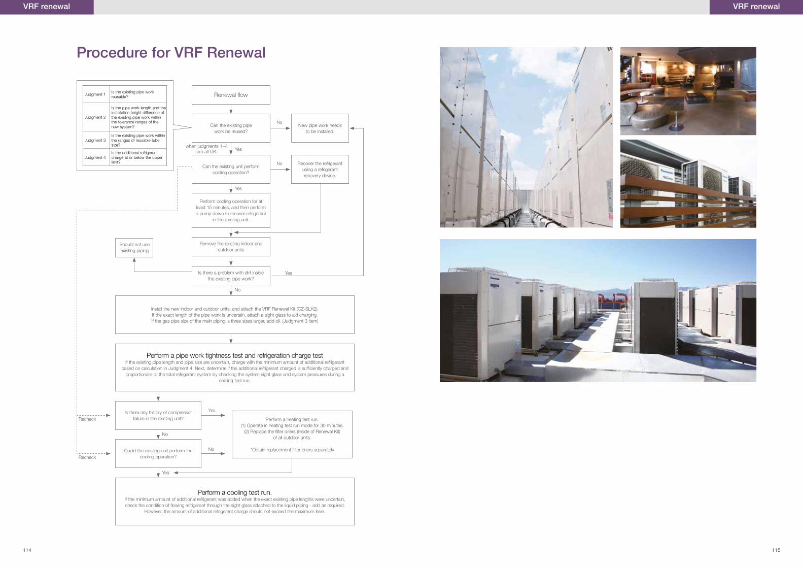
Judgment 1 Is the existing pipe work reusable?
Judgment 2
Is the pipe work length and the installation height difference of the existing pipe work within the tolerance ranges of the new system?
Judgment 3Is the existing pipe work within the ranges of reusable tube size?
Judgment 4Is the additional refrigerant charge at or below the upper limit?
Procedure for VRF Renewal
Renewal flow
Can the existing pipe work be reused?
New pipe work needs to be installed.
Can the existing unit perform cooling operation?
Is there a problem with dirt inside the existing pipe work?
Is there any history of compressor failure in the existing unit? Perform a heating test run.
(1) Operate in heating test run mode for 30 minutes.(2) Replace the �lter driers (inside of Renewal Kit)
of all outdoor units.
*Obtain replacement �lter driers separately.Could the existing unit perform the cooling operation?
Perform cooling operation for at least 15 minutes, and then perform a pump down to recover refrigerant
in the existing unit.
Install the new indoor and outdoor units, and attach the VRF Renewal Kit (CZ-SLK2).If the exact length of the pipe work is uncertain, attach a sight glass to aid charging.If the gas pipe size of the main piping is three sizes larger, add oil. (Judgment 3 item)
Perform a pipe work tightness test and refrigeration charge testIf the existing pipe length and pipe size are uncertain, charge with the minimum amount of additional refrigerant
based on calculation in Judgment 4. Next, determine if the additional refrigerant charged is suf�ciently charged and proportionate to the total refrigerant system by checking the system sight glass and system pressures during a
cooling test run.
Perform a cooling test run.If the minimum amount of additional refrigerant was added when the exact existing pipe lengths were uncertain, check the condition of �owing refrigerant through the sight glass attached to the liquid piping - add as required.
However, the amount of additional refrigerant charge should not exceed the maximum level.
Remove the existing indoor and outdoor units
Recover the refrigerant using a refrigerant recovery device.
Yes
Yeswhen judgments 1~4
are all OK
No
No
No
Yes
Yes
No
No
Recheck
Recheck
VRF renewalVRF renewal
Should not use existing piping
Yes
114 115

FSV-AU-2014-2015
Do not add or replace refrigerant other than the specified type.
Manufacturer is not responsible for the damage and deterioration in
safety due to usage of other refrigerant.
• Specifications are subject to change without prior notice for further improvement • The contents of this catalogue are effective as of May 2014
• Due to printing considerations, the actual colours may vary slightly from those shown • All graphics are provided merely for the purpose of illustrating a point.
EVERY BUILDING MATTERS