jan fischer-wolfarth gereon meyer editors advanced...
TRANSCRIPT

Lecture Notes in Mobility
AdvancedMicrosystemsfor Automotive Applications 2014
Jan Fischer-WolfarthGereon Meyer Editors
Smart Systems for Safe, Cleanand Automated Vehicles

Lecture Notes in Mobility
Series Editor
Gereon Meyer, VDI/VDE Innovation + Technik GmbH, Germanye-mail: [email protected]
For further volumes:
http://www.springer.com/series/11573

Jan Fischer-Wolfarth · Gereon MeyerEditors
Advanced Microsystems forAutomotive Applications 2014
Smart Systems for Safe, Clean andAutomated Vehicles
ABC

EditorsJan Fischer-WolfarthVDI/VDE Innovation + Technik GmbHBerlinGermany
Gereon MeyerVDI/VDE Innovation + Technik GmbHBerlinGermany
ISSN 2196-5544 ISSN 2196-5552 (electronic)ISBN 978-3-319-08086-4 ISBN 978-3-319-08087-1 (eBook)DOI 10.1007/978-3-319-08087-1Springer Cham Heidelberg New York Dordrecht London
Library of Congress Control Number: 2014941880
c© Springer International Publishing Switzerland 2014This work is subject to copyright. All rights are reserved by the Publisher, whether the whole or part ofthe material is concerned, specifically the rights of translation, reprinting, reuse of illustrations, recitation,broadcasting, reproduction on microfilms or in any other physical way, and transmission or informationstorage and retrieval, electronic adaptation, computer software, or by similar or dissimilar methodologynow known or hereafter developed. Exempted from this legal reservation are brief excerpts in connectionwith reviews or scholarly analysis or material supplied specifically for the purpose of being enteredand executed on a computer system, for exclusive use by the purchaser of the work. Duplication ofthis publication or parts thereof is permitted only under the provisions of the Copyright Law of thePublisher’s location, in its current version, and permission for use must always be obtained from Springer.Permissions for use may be obtained through RightsLink at the Copyright Clearance Center. Violationsare liable to prosecution under the respective Copyright Law.The use of general descriptive names, registered names, trademarks, service marks, etc. in this publicationdoes not imply, even in the absence of a specific statement, that such names are exempt from the relevantprotective laws and regulations and therefore free for general use.While the advice and information in this book are believed to be true and accurate at the date of pub-lication, neither the authors nor the editors nor the publisher can accept any legal responsibility for anyerrors or omissions that may be made. The publisher makes no warranty, express or implied, with respectto the material contained herein.
Printed on acid-free paper
Springer is part of Springer Science+Business Media (www.springer.com)
Preface
There are two major trends that coincide in the current discussion about the auto-mobile of the future: The electrification of the powertrain on one hand and highlyautomated driving on the other. Both technology paths seem to fit very well withthe sustainability objectives of transportation policy as they aim to increase the ef-ficiency of mobility and energy consumption while improving the quality of life inurban areas. Besides just coinciding, however, there is a great potential for thesetrends to interact: Automation potentially increases driving ranges, usability and af-fordability of electric vehicles, for example, by optimising traffic flow, valet parking,and inductive charging or anticipative use of the battery capacity. At the same time,electrification enables automated driving, for example, through easy integration ofdrive-by-wire controls, appropriate electric and electronic architecture, or accurateactuation and speed adjustments without gear shifts. There are also similarities inthe requirements of data communication and maps. One might argue that highlyautomated functionalities can be easily implemented into a conventional car andsimilarly into an electric one. It is, however, questionable if the public would accepta robot car based on an internal combustion engine as easily as one based on a cleanand silent electric powertrain.
The two future trends, electrification and automation, are essentially built on in-novations in the domain of smart systems such as sensors and actuators, adaptivecomponents and MEMS devices, novel electric and electronic architectures, intelli-gent interfaces, and their successful and synergetic integration. Therefore, the futuretechnology development in both of these trends is a main subject of the StrategicResearch Agenda of the European Technology Platform on Smart Systems Integra-tion (EPoSS) as well as the specific roadmaps derived from it, for example, the oneon road vehicle electrification jointly developed with the European Green VehiclesInitiative PPP or the one on road vehicle automation which is currently being es-tablished by a task force of EPoSS. The role of electronic components and systemsfor smart mobility is also emphasised in the Multi-Annual Strategic Research andInnovation Agenda of the new Joint Technology Initiative ECSEL in the frameworkof Horizon 2020.

vi Preface
Novel trends in key enabling technologies for the automobile and the synergiesbetween them have always been discussed at the International Forum on AdvancedMicrosystems for Automotive Applications (AMAA) at an early stage. Thus, thetopic of the AMAA 2014, held in Berlin on June 23–24, 2014, is “Smart Systemsfor Safe, Clean and Automated Vehicles”. The AMAA organisers, VDI/VDE Inno-vation + Technik GmbH together with the European Technology Platform on SmartSystems Integration (EPoSS), greatly acknowledge the support given for this confer-ence from the European Union through the Coordination Actions CAPIRE, SmartEV-VC, and GO4SEM.
The papers in this book, a volume of the Lecture Notes in Mobility series, werewritten by leading engineers and researchers who have attended the AMAA 2014conference to report their recent progress in research and innovation. The paperswere peer-reviewed by the members of the AMAA Steering Committee and aremade accessible worldwide.
As the co-chairman and chairman of the AMAA 2014, we would like to expressour deepest gratitude to all the authors for their high quality contributions to theconference and also to this book. We would also like to gratefully acknowledge thetremendous support we have received from our colleagues at VDI/VDE-IT, espe-cially Beate Müller, Christian Martin, and Sebastian Stagl.
Berlin, June 2014 Jan Fischer-WolfarthGereon Meyer

Advanced Microsystems for AutomotiveApplications 2014
Funding Authority
European Commission
Supporting Organisations
European Council for Automotive R&D (EUCAR)European Association of Automotive Suppliers (CLEPA)Strategy Board on Electric Mobility (eNOVA)Advanced Driver Assistance Systems in Europe (ADASE)Zentralverband Elektrotechnik- und Elektronikindustrie e.V. (ZVEI)Mikrosystemtechnik Baden-Württemberg e.V.
Organisers
European Technology Platform on Smart Systems Integration (EPoSS)VDI|VDE Innovation + Technik GmbH

Steering Committee
Mike Babala TRW Automotive, Livonia MI, USASerge Boverie Continental AG, Toulouse, FranceGeoff Callow Technical & Engineering Consulting, London,
UKKay Fürstenberg Sick AG, Hamburg, GermanyWolfgang Gessner VDI|VDE-IT, Berlin, GermanyRoger Grace Roger Grace Associates, Naples, FL, USAKlaus Gresser BMW Forschung und Technik GmbH,
Munich, GermanyRiccardo Groppo Ideas & Motion, Cavallermaggiore, ItalyHannu Laatikainen Murata Electronics Oy, Vantaa, FinlandJochen Langheim ST Microelectronics, Paris, FranceGünter Lugert Siemens AG, Munich, GermanySteffen Müller NXP Semiconductors, Hamburg, GermanyRoland Müller-Fiedler Robert Bosch GmbH, Stuttgart, GermanyAndy Noble Ricardo Consulting Engineers Ltd.
Shoreham-by-Sea, UKPietro Perlo IFEVS, Sommariva del Bosco, ItalyChristian Rousseau Renault SA, Guyancourt, FranceJürgen Valldorf VDI|VDE-IT, Berlin, GermanyDavid Ward MIRA Ltd., Nuneaton, UK
Conference Chairs
Gereon Meyer VDI|VDE-IT, Berlin, GermanyJan Fischer-Wolfarth VDI|VDE-IT, Berlin, Germany

Contents
Part I Driver Assistance and Vehicle Automation
Evolution in Advanced Driver Assistance: From Steering Supportin Highway Construction Zones to Assistance in Urban Narrow RoadScenarios . . . . . . . . . . . . . . . . . . . . . . . . . . . . . . . . . . . . . . . . . . . . . . . . . . . . . 3Thomas Paul Michalke, Thomas Gußner, Lutz Bürkle, Frank Niewels
Smart and Green ACC: As Applied to a Through the Road HybridElectric Vehicle . . . . . . . . . . . . . . . . . . . . . . . . . . . . . . . . . . . . . . . . . . . . . . . . 15Sagar Akhegaonkar, Sebastien Glaser, Lydie Nouveliere,Frederic Holzmann
Layer-Based Multi-Sensor Fusion Architecture for Cooperativeand Automated Driving Application Development . . . . . . . . . . . . . . . . . . . 29Maurice Kwakkernaat, Tjerk Bijlsma, Frank Ophelders
Design of Real-Time Transition from Driving Assistance toAutomation Function: Bayesian Artificial Intelligence Approach . . . . . . . 39Ata M. Khan
Enhancing Mobility Using Innovative Technologies and HighlyFlexible Autonomous Vehicles . . . . . . . . . . . . . . . . . . . . . . . . . . . . . . . . . . . . 49Timo Birnschein, Christian Oekermann, Mehmed Yüksel,Benjamin Girault, Roman Szczuka, David Grünwald,Sven Kroffke, Mohammed Ahmed, Yong-Ho Yoo, Frank Kirchner
Part II Networked Vehicles, ITS and Road Safety
Assessing the Evolution of E/E Hardware Modules with ConceptualFunction Architectures . . . . . . . . . . . . . . . . . . . . . . . . . . . . . . . . . . . . . . . . . . 61Stefan Raue, Markus Conrath, Bernd Hedenetz, Wolfgang Rosenstiel

x Contents
Increased Consumption in Oversaturated City Traffic Based onEmpirical Vehicle Data . . . . . . . . . . . . . . . . . . . . . . . . . . . . . . . . . . . . . . . . . . 71Peter Hemmerle, Micha Koller, Hubert Rehborn, Gerhard Hermanns,Boris S. Kerner, Michael Schreckenberg
An Active Vulnerable Road User Protection Based on One 24 GHzAutomotive Radar . . . . . . . . . . . . . . . . . . . . . . . . . . . . . . . . . . . . . . . . . . . . . . 81Michael Heuer, Marc-Michael Meinecke, Estrela Álvarez,Marga Sáez Tort, Francisco Sánchez, Stefano Mangosio
Power Saving in Automotive Ethernet . . . . . . . . . . . . . . . . . . . . . . . . . . . . . 93Thomas Suermann, Steffen Müller
Analysis of Cluster Ring Controller/Area Networks for EnhancedTransmission and Fault-Tolerance in Vehicle Networks . . . . . . . . . . . . . . . 101Po-Cheich Chiu, Yar-Sun Hsu, Ching-Te Chiu
Context-Based Service Fusion for Personalized On-Board InformationSupport . . . . . . . . . . . . . . . . . . . . . . . . . . . . . . . . . . . . . . . . . . . . . . . . . . . . . . 111Alexander Smirnov, Nikolay Shilov, Aziz Makklya, Oleg Gusikhin
Prediction of Switching Times of Traffic Actuated Signal ControlsUsing Support Vector Machines . . . . . . . . . . . . . . . . . . . . . . . . . . . . . . . . . . 121Toni Weisheit, Robert Hoyer
Part III Vehicle Efficiency and Green Power Trains
Predictive Optimization of the Operating Strategy in FutureVolkswagen Vehicles . . . . . . . . . . . . . . . . . . . . . . . . . . . . . . . . . . . . . . . . . . . . 133Jan Bellin, Norbert Weiss, Matthias Breuel, Michael Kurrat,Christoph Stamprath
(Cost)-Efficient System Solutions e.g. Integrated Battery Management,Communication and Module Supply for the 48V Power Supply inPassenger Cars . . . . . . . . . . . . . . . . . . . . . . . . . . . . . . . . . . . . . . . . . . . . . . . . 143Harald Gall, Manfred Brandl, Martin Jaiser, Johann Winter,Wolfgang Reinprecht, Josef Zehetner
Safety Simulation in the Concept Phase: Advanced Co-simulationToolchain for Conventional, Hybrid and Fully Electric Vehicles . . . . . . . . 153Stephen Jones, Eric Armengaud, Hannes Böhm, Caizhen Cheng,Gerhard Griessnig, Arno Huss, Emre Kural, Mihai Nica
When Do We Get the Electronic Battery Switch? . . . . . . . . . . . . . . . . . . . . 165Werner Rößler

Contents xi
On Board Energy Management Algorithm Based on Fuzzy Logic foran Urban Electric Bus with Hybrid Energy Storage System . . . . . . . . . . . 179Davide Tarsitano, Laura Mazzola, Ferdinando Luigi Mapelli,Stefano Arrigoni, Federico Cheli, Feyza Haskaraman
Part IV Vehicle Electrification
COSIVU - Compact, Smart and Reliable Drive Unit for CommercialElectric Vehicles . . . . . . . . . . . . . . . . . . . . . . . . . . . . . . . . . . . . . . . . . . . . . . . 191Tomas Gustafsson, Stefan Nord, Dag Andersson, Klas Brinkfeldt,Florian Hilpert
Development of a Solid-Borne Sound Sensor to Detect Bearing FaultsBased on a MEMS Sensor and a PVDF Foil Sensor . . . . . . . . . . . . . . . . . . 201Jurij Kern, Carsten Thun, Jernej Herman
Compact, Safe and Efficient Wireless and Inductive Chargingfor Plug-In Hybrids and Electric Vehicles . . . . . . . . . . . . . . . . . . . . . . . . . . 213André Körner, Faical Turki
Reliability of New SiC BJT Power Modules for Fully ElectricVehicles . . . . . . . . . . . . . . . . . . . . . . . . . . . . . . . . . . . . . . . . . . . . . . . . . . . . . . . 235Alexander Otto, Eberhard Kaulfersch, Klas Brinkfeldt, Klaus Neumaier,Olaf Zschieschang, Dag Andersson, Sven Rzepka
A Framework for Design, Test, and Validation of Electric CarModules . . . . . . . . . . . . . . . . . . . . . . . . . . . . . . . . . . . . . . . . . . . . . . . . . . . . . . 245Mehmed Yüksel, Mohammed Ahmed, Benjamin Girault, TimoBirnschein, Frank Kirchner
Application of Li-Ion Cell Aging Models on Automotive ElectricalPropulsion Cells . . . . . . . . . . . . . . . . . . . . . . . . . . . . . . . . . . . . . . . . . . . . . . . 255Davide Tarsitano, Federico Perelli, Francesco Braghin,Ferdinando Luigi Mapelli, Zhi Zhang
Part V Components and Systems
Visualisation Functions in Advanced Camera-Based Surround ViewSystems . . . . . . . . . . . . . . . . . . . . . . . . . . . . . . . . . . . . . . . . . . . . . . . . . . . . . . . 267Markus Friebe, Johannes Petzold

xii Contents
Evaluation of Angular Sensor Systems for Rotor Position Sensing ofAutomotive Electric Drives . . . . . . . . . . . . . . . . . . . . . . . . . . . . . . . . . . . . . . 277Jens Gächter, Jürgen Fabian, Mario Hirz, Andreas Schmidhofer,Heinz Lanzenberger
Future Trends of Advanced Power Electronics and Control Systemsfor Electric Vehicles . . . . . . . . . . . . . . . . . . . . . . . . . . . . . . . . . . . . . . . . . . . . 287Jürgen Fabian, Jens Gächter, Mario Hirz
Author Index . . . . . . . . . . . . . . . . . . . . . . . . . . . . . . . . . . . . . . . . . . . . . . . . . . . . . 297
Subject Index . . . . . . . . . . . . . . . . . . . . . . . . . . . . . . . . . . . . . . . . . . . . . . . . . . . . . 299

Contributors
Mohammed Ahmed DFKI GmbH - Robotics Innovation Center, Robert-Hooke-Str. 5, 28359 Bremen, Germany, email: [email protected]
Sagar Akhegaonkar INTEDIS GmbH & Co. KG, Max-Mengeringhausen-Str. 5,97084 Wuerzburg, Germany, email: [email protected]
Estrela Álvarez Centro Tecnológico de Automoción de Galicia, Pol. IndustrialA Granxa, Calle A, Parcela 249-250, 36400, Porriño (Pontevedra), Spain,email: [email protected]
Dag Andersson Swerea IVF AB, PO Box 104, 43122 Mölndal, Sweden,email: [email protected]
Eric Armengaud AVL List GmbH, Hans-List-Platz 1, 8020 Graz, Austria,email: [email protected]
Stefano Arrigoni Politecnico di Milano, Department of Mechanics, via La Masa 1,Milan, Italy, email: [email protected]
Jan Bellin Volkswagen AG, elenia TU-Braunschweig, Rosenweg 11, 30627 Han-nover, Germany, email: [email protected]
Tjerk Bijlsma TNO, Steenovenweg 1, 5708 HN Helmond, The Netherlands,email: [email protected]
Timo Birnschein DFKI GmbH - Robotics Innovation Center, Robert-Hooke-Str. 5,28359 Bremen, Germany, email: [email protected]
Hannes Böhm AVL List GmbH, Hans-List-Platz 1, 8020 Graz, Austria,email: [email protected]
Francesco Braghin Politecnico di Milano, Department of Mechanics, via La Masa1, Milan, Italy, email: [email protected]

xiv Contributors
Manfred Brandl ams AG, Tobelbaderstr. 30, 8141 Unterpremstaetten, Austria,email: [email protected]
Matthias Breuel Volkswagen AG, Volkswagen AG, EEF, 38440 Wolfsburg, Ger-many, email: [email protected]
Klas Brinkfelt Swerea IVF AB, PO Box 104, 43122 Mölndal, Sweden, email:[email protected]
Lutz Bürkle Robert Bosch GmbH, Corporate Research (CR/AEV2) 12, 70442Stuttgart, Germany, email: [email protected]
Federico Cheli Politecnico di Milano, Department of Mechanics, via La Masa 1,Milan, Italy, email: [email protected]
Caizhen Cheng AVL List GmbH, Hans-List-Platz 1, 8020 Graz, Austria,email: [email protected]
Po-Cheich Chiu National Tsing Hua University, Department of Electrical Engi-neering, Guangfu Rd. Sec. 101, Hsinchu, Taiwan 30013, R.O.C.,email: [email protected]
Ching-Te Chiu National Tsing Hua University, Department of Computer Science,Institute of Communications Engineering, Guangfu Rd. Sec. 101, Hsinchu, Taiwan30013, R.O.C.
Markus Conrath Daimler AG, Architecture & Body Controller, HPC G007-BB,71059 Sindelfingen, Germany, email: [email protected]
Jürgen Fabian Graz University of Technology, Institute of Automotive Engineer-ing, Inffeldgasse 11/2, 8010 Graz, Austria, email: [email protected]
Markus Friebe Continental AG, BU ADAS, Segment Surround View, Johann-Knoch-Gasse 9, 96317 Kronach, Germany,email: [email protected]
Jens Gächter Graz University of Technology, Institute of Automotive Engineering,Inffeldgasse 11/2, 8010 Graz, Austria, email: [email protected]
Harald Gall ams AG, Tobelbaderstr. 30, 8141 Unterpremstaetten, Austria,email: [email protected]
Benjamin Girault DFKI GmbH - Robotics Innovation Center, Robert-Hooke-Str.5, 28359 Bremen, Germany, email: [email protected]
Sebastien Glaser LIVIC, 77 rue de Chantiers, 78000 Versailles, France,email: [email protected]
Gerhard Griessnig AVL List GmbH, Hans-List-Platz 1, 8020 Graz, Austria,email: [email protected]

Contributors xv
David Grünwald DFKI GmbH - Robotics Innovation Center, Robert-Hooke-Str. 5,28359 Bremen, Germany, email: [email protected]
Oleg Gusikhin Ford Motor Company, P.O. Box 6248, Dearborn, MI 48126, USA,email: [email protected]
Thomas Gußner Robert Bosch GmbH, Corporate Research (CR/AEV2) 12, 70442Stuttgart, Germany, email: [email protected]
Tomas Gustafsson Volvo Group Trucks Technology, Advanced Technology andResearch, Götaverksgatan 10, 40508 Göteborg, Sweden,email: [email protected]
Feyza Haskaraman Massachusetts Institute of Technology, Department of Me-chanical Engineering, Cambridge, MA, USA, email: [email protected]
Bernd Hedenetz Daimler AG, Architecture & Body Controller, HPC G007-BB,71059 Sindelfingen, Germany, email: [email protected]
Peter Hemmerle Daimler AG, HPC: 059-X832, 71063 Sindelfingen, Germany,email: peter.hemmerledaimler.com
Jernej Herman Elaphe Propulsion Technologies Ltd., Babno 20a, 3000 Celje,Slovenia, email: [email protected]
Gerhard Hermanns Universität Duisburg-Essen, Physik von Transport und Verkehr,Lotharstr. 1, 47057 Duisburg, Germany, email: [email protected]
Michael Heuer Otto-von-Guericke-University of Magdeburg, Universitätsplatz 2,39106 Magdeburg, Germany, email: [email protected]
Florian Hilpert Fraunhofer Institute for Integrated Systems and Device Technol-ogy IISB, Drives and Mechatronics, Schottkystr. 10, 91058 Erlangen, Germany,email: [email protected]
Mario Hirz Graz University of Technology, Institute of Automotive Engineering,Inffeldgasse 11/2, 8010 Graz, Austria, email: [email protected]
Frederic Holzmann INTEDIS GmbH & Co. KG, Max-Mengeringhausen-Str. 5,97084 Wuerzburg, Germany, email: [email protected]
Robert Hoyer University of Kassel, Department of Traffic Engineering and Trans-port Logistics, Mönchebergstr. 7, 34125 Kassel, Germany,email: [email protected]
Yar-Sun Hsu National Tsing Hua University, Department of Electrical Engineer-ing, Guangfu Rd. Sec. 101, Hsinchu, Taiwan 30013, R.O.C.
Arno Huss AVL List GmbH, Hans-List-Platz 1, 8020 Graz, Austria,email: [email protected]

xvi Contributors
Martin Jaiser ams Germany GmbH, Erdinger Str. 14, 85609 Aschheim b. München,Germany, email: [email protected]
Stephen Jones AVL List GmbH, Hans-List-Platz 1, 8020 Graz, Austria,email: [email protected]
Eberhard Kaulfersch Berliner Nanotest und Design GmbH, Volmerstr. 9B, 12489Berlin, Germany, email: [email protected]
Jurij Kern Elaphe Propulsion Technologies Ltd., Luznarjeva 3, 4000 Kranj, Slove-nia, email: [email protected]
Boris S. Kerner Universität Duisburg-Essen, Physik von Transport und Verkehr,Lotharstr. 1, 47057 Duisburg, Germany, email: [email protected]
Ata M. Khan Carleton University, 1125 Colonel By Drive, Ottawa, Ontario, K1S5B6, CANADA, [email protected]
Frank Kirchner, DFKI GmbH - Robotics Innovation Center, Department of Math-ematics and Computer Science, University of Bremen, Robert-Hooke-Str. 1, 28359Bremen, Germany, email: [email protected]
André Körner Hella KGaA Hueck & Co., Beckumer Str. 130, 59555 Lippstadt,Germany, email: [email protected]
Micha Koller IT-Designers GmbH, Entennest 2, 73730 Esslingen, Germany,email: [email protected]
Sven Kroffke DFKI GmbH - Robotics Innovation Center, Robert-Hooke-Str. 5,28359 Bremen, Germany, email: [email protected]
Emre Kural AVL List GmbH, Hans-List-Platz 1, 8020 Graz, Austria,email: [email protected]
Michael Kurrat elenia TU Braunschweig, Schleinitzstr. 23, 38106 Braunschweig,Germany, email: [email protected]
Maurice Kwakkernaat TNO, Steenovenweg 1, 5708 HN Helmond, The Nether-lands, email: [email protected]
Heinz Lanzenberger MAGNA Powertrain AG & Co KG, Project House Europe,Frank Stronach-Straße 3, 8200 Albersdorf, Austria,email: [email protected]
Aziz Makklya Ford Motor Company, P.O. Box 6248, Dearborn, MI 48126, USA,email: [email protected]
Stefano Mangosio, Centro Ricerche Fiat, Strada Torino 50, 10043 Orbassano, Italy,email: [email protected]

Contributors xvii
Ferdinando Luigi Mapelli Politecnico di Milano, Department of Mechanics, viaLa Masa 1, Milan, Italy, email: [email protected]
Laura Mazzola Politecnico di Milano, Department of Mechanics, via La Masa 1,Milan, Italy, email: [email protected]
Marc-Michael Meinecke Volkswagen AG, Brieffach 1777, Berliner Ring 2, 38440Wolfsburg, Germany, email: [email protected]
Thomas Paul Michalke Robert Bosch GmbH, Corporate Research (CR/AEV2) 12,70442 Stuttgart, Germany, email: [email protected]
Steffen Müller NXP Semiconductors Germany GmbH, Stresemannallee 101, Ham-burg, Germany, [email protected]
Klaus Neumaier Fairchild Semiconductor GmbH, Technology DevelopmentCenter, Einsteinring 28, 85609 Aschheim, Germany,email: [email protected]
Mihai Nica AVL List GmbH, Hans-List-Platz 1, 8020 Graz, Austria,email: [email protected]
Frank Niewels Robert Bosch GmbH, Corporate Research (CR/AEV2) 12, 70442Stuttgart, Germany, email: [email protected]
Stefan Nord Volvo Group Trucks Technology, Advanced Technology and Research,Götaverksgatan 10, 40508 Göteborg, Sweden, email: [email protected]
Lydie Nouveliere LIVIC, 77 rue de Chantiers, 78000 Versailles, France,email: [email protected]
Christian Oekermann DFKI GmbH - Robotics Innovation Center, Robert-Hooke-Str. 5, 28359 Bremen, Germany, email: [email protected]
Frank Ophelders TNO, Steenovenweg 1, 5708 HN Helmond, The Netherlands,email: [email protected]
Alexander Otto Fraunhofer Institute for Electronic Nano Systems ENAS, Depart-ment Micro Materials Center, Technologie-Campus 3, 09126 Chemnitz, Germany,email: [email protected]
Federico Perelli Politecnico di Milano, Department of Mechanics, via La Masa 1,Milan, Italy, email: [email protected]
Johannes Petzold Continental AG, BU ADAS, Segment Surround View, Johann-Knoch-Gasse 9, 96317 Kronach, Germany,email: [email protected]
Stefan Raue Daimler AG, Architecture & Body Controller, HPC G007-BB, 71059Sindelfingen, Germany, email: [email protected]

xviii Contributors
Hubert Rehborn Daimler AG, HPC: 059-X832, 71063 Sindelfingen, Germany,email: [email protected]
Wolfgang Reinprecht ams AG, Tobelbaderstr. 30, 8141 Unterpremstaetten, Aus-tria, email: [email protected]
Werner Rößler Infineon Technologies AG, Automotive System Engineering, AmCampeon 1-12, 85579 Neubiberg, Germany, email: [email protected]
Wolfgang Rosenstiel University of Tübingen, Computer and Engineering Depart-ment, Auf der Morgenstelle 8, 72076 Tübingen, Germany,email: [email protected]
Sven Rzepka Fraunhofer Institute for Electronic Nano Systems ENAS, DepartmentMicro Materials Center, Technologie-Campus 3, 09126 Chemnitz, Germany,email: [email protected]
Marga Sáez Centro Tecnológico de Automoción de Galicia, Pol. Industrial AGranxa, Calle A, Parcela 249-250, 36400, Porriño (Pontevedra), Spain,email: [email protected]
Francisco Sánchez Centro Tecnológico de Automoción de Galicia, Pol. IndustrialA Granxa, Calle A, Parcela 249-250, 36400, Porriño (Pontevedra), Spain,email: [email protected]
Andreas Schmidhofer MAGNA Powertrain AG & Co KG, Project House Europe,Frank Stronach-Straße 3, 8200 Albersdorf, Austria,email: [email protected]
Michael Schreckenberg Universität Duisburg-Essen, Physik von Transport undVerkehr, Lotharstr. 1, 47057 Duisburg, Germany,email: [email protected]
Nikolay Shilov St. Petersburg Institute for Informatics and Automation of the Rus-sian Academy of Sciences (SPIIRAS), 39, 14 Line, St. Petersburg, 199178, Russia,email: [email protected]
Alexander Smirnov St. Petersburg Institute for Informatics and Automation of theRussian Academy of Sciences (SPIIRAS), 39, 14 Line, St. Petersburg, 199178, Rus-sia, email: [email protected]
Christoph Stamprath elenia TU-Braunschweig, Am Flughafen 13, 38110 Braun-schweig, Germany, email: [email protected]
Thomas Suermann NXP Semiconductors Germany GmbH, Stresemannallee 101,Hamburg, Germany, email: [email protected]
Roman Szczuka DFKI GmbH - Robotics Innovation Center, Robert-Hooke-Str. 5,28359 Bremen, Germany, email: [email protected]
Contributors xix
Davide Tarsitano Politecnico di Milano, Department of Mechanics, via La Masa 1,Milan, Italy, email: [email protected]
Carsten Thun Hella Fahrzeugkomponenten GmbH, Dortmunderstr. 5, 28199 Bre-men, Germany, email: [email protected]
Faical Turki Paul Vahle GmbH & Co. KG, Westicker Strasse 52, 59174 Kamen,Germany, email: [email protected]
Toni Weisheit University of Kassel, Department of Traffic Engineering and Trans-port Logistics, Mönchebergstr. 7, 34125 Kassel, Germany,email: [email protected]
Norbert Weiss Volkswagen AG, Volkswagen AG, EAEF/2, 38440 Wolfsburg, Ger-many, email: [email protected]
Johann Winter ams Germany GmbH, Erdinger Str. 14, 85609 Aschheim b. München,Germany, email: [email protected]
Yong-Ho Yoo DFKI GmbH - Robotics Innovation Center, Robert-Hooke-Str. 1,28359 Bremen, Germany, email: [email protected]
Mehmed Yüksel DFKI GmbH - Robotics Innovation Center, Robert-Hooke-Str. 5,28359 Bremen, Germany, email: [email protected]
Josef Zehetner Virtual Vehicle Research Center, Inffeldgasse 21/A, 8010 Graz,Austria, email: [email protected]
Zhi Zhang Politecnico di Milano, Department of Mechanics, via La Masa 1, Milan,Italy, email: [email protected]
Olaf Zschieschang Fairchild Semiconductor GmbH, Technology DevelopmentCenter, Einsteinring 28, 85609 Aschheim, Germany,email: [email protected]

Part I Driver Assistance and Vehicle
Automation

J. Fischer-Wolfarth and G. Meyer (eds.), Advanced Microsystems for Automotive Applications 2014, Lecture Notes in Mobility,
3
DOI: 10.1007/978-3-319-08087-1_1, © Springer International Publishing Switzerland 2014
Evolution in Advanced Driver Assistance: From Steering Support in Highway Construction Zones to Assistance in Urban Narrow Road Scenarios(
Thomas Paul Michalke, Thomas Gußner, Lutz Bürkle and Frank Niewels
Abstract. With the advances in environment sensor technology, advanced driver assistance systems (ADAS) that target increasingly complex scenarios such as inner-city traffic get into focus. Such novel ADAS will offer assistance in a wide range of urban traffic scenarios and, thus, will further decrease the number and severity of accidents. In this contribution, the evolution of an ADAS for lateral guidance in highway construction zones (i.e. the “construction zone assistant”) towards assistance in narrow urban road scenarios (i.e. the “urban narrow road assistant”) is presented. The focus of the contribution will be on the challenges of these two scenario types and their respective requirements on the system concept and design. While steering support in highway construction zones will be availa-ble on the market soon, its functional extension to inner-city traffic is still charac-terized by numerous technological challenges. Due to that, the emphasis in terms of algorithmic details will be on the “urban narrow road assistant”.
Keywords: Construction zones, UR:BAN, automated steering support, driver assistance in inner-city, automated lateral control.
1 Introduction
In recent years, numerous prototypical ADAS have been developed that target the automated longitudinal and lateral control of vehicles (refer e.g. to [1-3]). Alt-hough highly demanding in terms of the complexity and number of use-cases to be covered, such systems can benefit from the restricted interaction between driver and system. Hence, on an operational level a correctly operating automated vehi-cle does not have to interact and cooperate with the driver’s intentions. Therefore,
T.P. Michalke() · T. Gußner · L. Bürkle · F. Niewels Robert Bosch GmbH, Corporate Research (CR/AEV2), 70442 Stuttgart, Germany e-mail: {thomas.michalke,thomas.gussner,lutz.buerkle,frank.niewels}@de.bosch.com

4 T.P. Michalke et al.
in such systems no driver intention recognition is required. In addition to still un-resolved technical issues, also well-known legal restrictions apply [4] which might considerably delay the realization of highly automated vehicles. Due to these re-strictions, the realization of driver assistance as well as partly automated systems is a necessary intermediate development step on the path to full automation. The evolution of close-to-market systems for lateral guidance assistance is in the focus of this contribution. Since the driver remains involved and responsible, especially in complex scenarios driver intention recognition becomes mandatory.
Driver assistance systems for supporting the driver to stay in the lane have been available on the market since several years. Such lane keeping systems intervene by an acoustic warning or a haptic feedback on the steering wheel (refer to [5]). Furthermore, an active steering intervention based on superimposing steering tor-ques (refer to [6, 7]) or by asymmetric braking interventions are on the market. These and other earlier lane keeping systems depend on the existence and precise detection of lane markings. More recent systems support the driver in construction sites on highways (refer to [8, 9]) and therefore rely on the detection of static and dynamic obstacles. Also the here referenced “construction zone assistant” (see Section 2) belongs to that category.
Novel systems (as e.g. the “urban narrow road assistant” presented in Section 3) currently under development explicitly focus on actively supporting the driver in inner-city traffic scenarios. As a common characteristic, such systems rely on the detection and measurement of obstacles. Based on that, the optimal vehicle trajectory is inferred. Dependent on the trajectory, lateral steering support is of-fered in order to prevent collisions with objects positioned laterally. Lateral guid-ance systems are typically classified as comfort systems while still having inherent characteristics of safety systems. When focusing on close-to-market systems of the latter type, only few related contributions exist. For example, in the context of the publicly-funded project “V-Charge” (refer to [10, 11]) an ADAS was devel-oped that supports the driver in stationary traffic and parking maneuvers in inner-city. Different from the here presented two ADAS, the system is restricted to an ego-velocity in the range of walking speed and to scenarios without dynamic obstacles.
In the following, an overview on the two functions “construction zone assis-tant” and “urban narrow road assistant” is given. The focus is on the major use-cases as well as the resulting respective challenges in system design.
2 Construction Zone Assistant
This section focuses on the “construction zone assistant” (CZA). First, we briefly describe the function and then discuss necessary sensors as well as actuators and give an overview on the system architecture. Then, with the environment model-ing and the driving corridor estimation two key algorithms of the system are described in more detail. Finally, the typical use-cases the system is capable to

Evolution in Advanced Driver Assistance 5
deal with as well the main limitations of the system are briefly discussed. For further information on the CZA refer to [8,9].
2.1 Function Description
The objective of the CZA is to support the driver in highway construction zones in order to keep a safe lateral distance to static infrastructure objects such as walls or traffic cones as well as to dynamic objects such as other cars or trucks travelling in neighboring lanes. In a typical use-case the driver is supported while overtaking a slower truck in a construction site resulting in a narrow driving corridor (see Fig.2b). In contrast to usual highway scenarios with marked lanes that define the driving corridor, lane markings in construction sites are often ambiguous or even not present at all. The system is supporting the driver in maintaining a collision free path by applying an appropriate steering torque whenever the driver steers in the direction of an obstacle. If appropriate, the system additionally informs the driver about the available lateral distance to objects and the width of the driving corridor ahead of the vehicle.
The function assists the driver at velocities ranging from 60 kph to 100 kph, which are typical for construction zones on highways. The availability of the sys-tem is limited to highway construction zones, which allows for simplifying as-sumptions on the infrastructure and the dynamics of other vehicles.
2.2 System Overview
The environment sensor setup of the CZA consists of a sensor capable of observ-ing the space ahead of the vehicle as well as sensors observing the area next to the vehicle on both sides. A front facing sensor shall provide information on dynamic as well as static obstacles in order to be able to determine the driving corridor through the construction zone and to assist the driver in maintaining a collision free path. In addition, it is necessary to be able to detect and measure the distance to dynamic objects (i.e. other cars, trucks, etc.) driving outside of the field of view of the front sensor. Based on these requirements, we decided to equip a test-vehicle with a stereo-vision-camera (SV-camera) as a front sensor as well as four ultrasonic sensors (US-sensors) covering the space on both sides next to the vehi-cle. Furthermore, onboard sensors measuring yaw-rate, velocity, etc. are necessary to estimate and predict the motion of the ego-vehicle. Since the purpose of the system is to provide assisting steering torques in critical scenarios in construction zones, we use electrical power steering (EPS) as actuator. It can provide an addi-tional torque on the steering column that is superimposed to the torque provided by the driver on the steering wheel. To make sure that the driver can always over-rule the system, the superimposed steering torque is limited in terms of the abso-lute value as well as the rate of change.
Fig. 1 shows the system architecture that is employed to determine supporting steering torques from the sensor input signals.

6 T.P. Michalke et al.
Based on the two simultaneously recorded images of the SV-camera a disparity map (see e.g. [12]) is computed in sub-system 1. Afterwards, the amount of data to be processed in subsequent sub-systems is reduced by clustering the disparity map. Additionally, from pairs of images of subsequent frames, an optical flow field (see e.g. [13]) is estimated in order to be able to determine motion relative to the SV-camera. In parallel to the stereo-signal processing, the raw data of the US-sensors are processed resulting in measured radial distances of objects for each of the four US-sensors.
The purpose of the subsequent sub-system 2 is to provide a temporally stabi-lized representation of the free-space in front of and next to the vehicle based on the preprocessed sensor signals. Additionally, an object-list keeps track of the dynamic objects surrounding the vehicle. Using this representation, sub-system 3 computes a driving corridor based on several assumptions derived from the knowledge of being in a highway construction zone. Next, sub-system 4 predicts the motion of the ego-vehicle and checks the predicted trajectory for collisions with the borders of the driving corridor. If such a collision is predicted to occur, a collision-free trajectory is planned in sub-system 5, which finally results in a cor-recting steering torque superimposed by the EPS.
Fig. 1 System architecture of the “construction zone assistant” (bold elements differ from architecture of the “urban narrow road assistant”)
• stereo camera front• four ultrasonic-sensors to the sides
environment sensors
• object tracking• free-space-polygon estimation
2: Environment Model (EM)
• driving corridor computation• driving corridor prediction
3: Situation analysis (SIT)
• compute disparity map, optical flow, clustering• compute radial distances for ultrasonic-sensors
1: Sensor data processing
• predict ego-vehicle• check for imminent collisions with driving corridor boundaries
4: Action Planning & Control (APC)
• trajectory planning• control of lateral vehicle motion
5: Vehicle Motion Controller (VMC)
• display distance to lateral objects• display width of driving corridor ahead
Human Machine Interface (HMI)
• electric power steering
actuators for vehicle motion control
• acceleration, velocity, yaw-rate sensors• steering wheel torque, steering wheel angle
vehicle-internal sensors
• head-up display• instrument cluster
hardware for user interaction
sens
ors
func
tion
mod
ules
actu
ator
s

Evolution in Advanced Driver Assistance 7
2.3 Environment Model and Driving Corridor Estimation
This section describes the environment model in sub-system 2 and the estimation of the driving corridor, which represents the space, the vehicle can safely drive on, in sub-system 3. As soon as the vehicle is predicted to leave the driving corridor, a correcting steering torque is applied. Thus, the driving corridor plays a similar role as lanes do in lane assistance systems. However, the boundaries of the driving corridor are rather defined by static and dynamic obstacles than by lane markings.
The environment modeling algorithm uses the preprocessed sensor data from the SV-camera and the US-sensors to infer a compact representation of the envi-ronment employing certain assumptions especially on the temporal behavior of obstacles surrounding the vehicle. The first step in determining this representation is an object-tracking based on the assumption that all objects approximately main-tain a constant velocity. We use a classical Kalman-Filter approach to estimate position, dimensions, orientation and velocity of moving objects. Secondly, all stationary obstacles are represented by means of a polygon. This polygon describes either the boundary between the free-space in front of and next to the vehicle and any type of obstacle or the boundary of the field of view of the envi-ronment sensors, respectively. This approach differs from standard approaches using a Cartesian obstacle grid map representation e.g. described in [14]. Similar to the well known grid map estimation, we assume all obstacles to be static when temporally stabilizing the polygon representation applying recursive Bayes filter-ing techniques. The advantage of our approach is a lower demand of computation and memory resources, since only the corners describing the boundary polygon need to be stored and computed in contrast to storing and updating the state of each cell of the grid map. The downside of this approach is that the complexity of the environment that can be represented by the polygon model is limited. For in-stance, a region of free-space that is not connected to the free-space in front of the vehicle cannot be described. The environment is now represented by a list of dy-namic objects and a polygon describing the static world surrounding the vehicle.
Based on the stationary free-space-polygon and the list of dynamic objects, we determine the driving corridor, which consists of two polygons describing the corridors left hand and right hand side boundary, respectively. The driving corri-dor contains only those parts of the environment that the vehicle can reach from its current position. To this end, first, all paths that are too narrow for the vehicle to drive through are excluded. Furthermore, we exclude all areas that cannot be reached from the current position of the ego-vehicle without exceeding a certain velocity dependent yaw rate. This threshold does not necessarily coincide with physical limits derived from vehicle dynamics, but is rather derived from yaw-rates which are usually not exceeded in driving through highway construction zones. The driving corridor can also be used to inform the driver about narrow spots ahead, e.g. between a wall and a truck the driver intents to overtake.
This representation of the driving-corridor still is time-dependent, since it may contain corners resulting from dynamic objects with non-zero velocity. Depending on the trajectory-planning-algorithm employed to find a collision free trajectory in
8 T.P. Michalke et al.
case of an imminent collision with the driving-corridor boundaries, it might be necessary to eliminate this time-dependency by predicting all non-stationary poly-gon corners assuming constant velocities and afterwards rearranging the polygon corners appropriately.
2.4 Use-Cases and Limitations
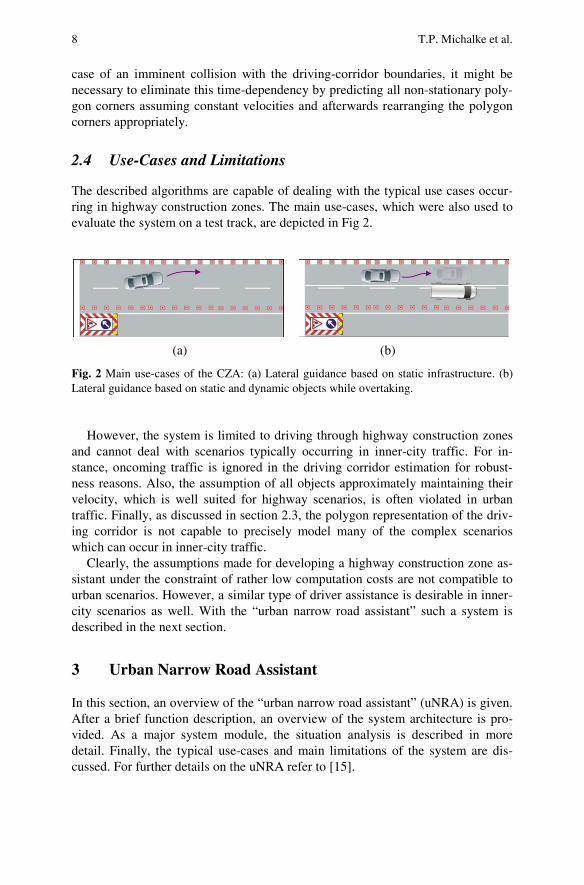
The described algorithms are capable of dealing with the typical use cases occur-ring in highway construction zones. The main use-cases, which were also used to evaluate the system on a test track, are depicted in Fig 2.
(a) (b)
Fig. 2 Main use-cases of the CZA: (a) Lateral guidance based on static infrastructure. (b) Lateral guidance based on static and dynamic objects while overtaking.
However, the system is limited to driving through highway construction zones
and cannot deal with scenarios typically occurring in inner-city traffic. For in-stance, oncoming traffic is ignored in the driving corridor estimation for robust-ness reasons. Also, the assumption of all objects approximately maintaining their velocity, which is well suited for highway scenarios, is often violated in urban traffic. Finally, as discussed in section 2.3, the polygon representation of the driv-ing corridor is not capable to precisely model many of the complex scenarios which can occur in inner-city traffic.
Clearly, the assumptions made for developing a highway construction zone as-sistant under the constraint of rather low computation costs are not compatible to urban scenarios. However, a similar type of driver assistance is desirable in inner-city scenarios as well. With the “urban narrow road assistant” such a system is described in the next section.
3 Urban Narrow Road Assistant
In this section, an overview of the “urban narrow road assistant” (uNRA) is given. After a brief function description, an overview of the system architecture is pro-vided. As a major system module, the situation analysis is described in more detail. Finally, the typical use-cases and main limitations of the system are dis-cussed. For further details on the uNRA refer to [15].

Evolution in Advanced Driver Assistance 9
3.1 Function Description
Similar to the CZA, the uNRA provides information about the lateral distance to static and dynamic objects. Typical use-cases are depicted in Fig.5. In case a safe lateral distance to obstacles is violated the system applies a steering torque. How-ever, in contrast to the CZA, the uNRA supports the driver in inner-city traffic. Consequently, the function is active at lower velocities ranging from 0 kph to 60 kph. The uNRA is required to handle unstructured surroundings typically found in cities (parking cars, poles, traffic islands, curb stones, etc.). As a consequence, the uNRA requires more sophisticated means to represent and interpret the environ-ment. These will be a major focus of this contribution.
3.2 System Overview
Following the system architecture in Fig. 3, the uNRA relies on a multi-camera system consisting of a front-facing stereo video camera and distributed body cam-eras as environment sensors. In addition, various vehicle-internal sensors are used (e.g. velocity, acceleration, yaw-rate, and steering wheel angle sensors). The sen-sor data is post-processed in the data preparation and validation module (DPV), after which it is transformed to standard units and validated with respect to signal range and consistency.
The environment sensors provide a 3D representation of the vehicle surround-ing which is used as input for an environment model (EM). Here the data of individual sensors is fused and represented as an occupancy grid, a free-space representation, and object models, respectively. The occupancy grid represents the static collision-relevant environment. The free-space represents the road surface that was measured to be drivable. Dynamic traffic participants are represented and tracked as objects. The application of a grid representation stems from the fact that the uNRA is required to operate in unstructured inner-city surroundings that can-not be represented with classical object-model-driven approaches (refer to [16] for more details).
In the situation analysis module (SIT) the occupancy grid and free-space are post-processed and combined resulting in the driving corridor. Furthermore, with-in the SIT a use-case classification and driver intention recognition are realized. Finally, different criticality measures are computed that determine the system state in the following action planning and control (APC) module. The APC furthermore checks if system boundaries are exceeded (e.g. thresholds for lateral and longitu-dinal ego-acceleration and road curvature). Dependent on the system state the ADAS will remain inactive (e.g. no critical situation), offer information (e.g. nar-row road section ahead), a collision warning or steering support, respectively. Information and warnings are displayed through the human machine interface (HMI) module. Steering support is realized by the vehicle motion control (VMC) module. The latter two modules control the required hardware (e.g. displays or electric power steering).

10 T.P. Michalke et al.
Fig. 3 System overview “urban narrow road assistant” (bold elements differ from CZA architecture)
3.3 Situation Analysis
The SIT module has the task to interpret the scenario by determining the relations between objects. Referring to the SIT sub-system overview in Fig. 4, in a first step the stationary occupancy grid (representing the static collision-relevant environ-ment) is fused to the grid representing drivable free-space. These representations are not necessarily complementary. For example, free-space is not necessarily limited by collision-relevant objects, since the latter can be measured in larger distances than the free-space. As a preparation step, on the occupancy grid a ray tracing can be realized. Hence, it is assumed that all space in the line-of-sight to an object is free. For a combination, a simple super-position of the ray-traced grid and the free-space can be realized, which results in the driving corridor. On the driving corridor a search for possible future ego-vehicle paths is realized. Only those paths are used for further processing that match the measurement-driven, predicted ego-trajectory. As a result, a collision-free path with or without branches is now available. For example, a branch can result when the driver has the two options: (a) Stop his vehicle on the right side of the road, (b) Overtake a parking vehicle. Depending on the recognized use-case, certain branches might be rejected
• multi-camera system (stereo camera front, 2 body cams to the sides)
environment sensors
• ego-vehicle localization• sensor data fusion (obstacle grid and free space)• object detection and tracking
Environment Model (EM)
• post-processing of obstacle grid and free space• use-case classification, driver intention recognition• computation of criticality measures
SITuation analysis (SIT)
• transformation to standard units and ISO-coordinate system• plausibility checks (signal range and model-based consistency tests)
Data Preparation & Validation (DPV)
• evaluation of system boundaries• determine system state (information, warning, intervention)
Action Planning & Control (APC)
• trajectory planning• control of lateral vehicle motion
Vehicle Motion Controller (VMC)
• display of situation-specific information• implementation of warn cascade
Human Machine Interface (HMI)
• electric power steering
actuators for vehicle motion control
• steering wheel angle sensor• braking and gas pedal position• acceleration, velocity, yaw-rate sensors
vehicle-internal sensors
• head-up display• instrument cluster
hardware for user interaction
sens
ors
func
tion
mod
ules
actu
ator
s

Evolution in Advanced Driv
(e.g. if the road is too narbranch, a decision point required to resolve the amvention or futile warningrealized relying on a Hiddriver's decision processedecision points, the resultdicted ego-trajectory. Basthe collision-relevant envVMC module that control
Fig. 4 Sub-system overview
3.4 Use-Cases and
The “urban narrow road sections in inner-city trafing steering support in a typical use-cases in a statiic objects).
(a)
Fig. 5 Use-cases for the uNsurroundings, (b) Narrow pa
occupancygrid
raytracing
freespace
drivcorri
CANdata
er Assistance 1
rrow and parking is no option). At path positions with is defined. Here recognition of the driver intention
mbiguity and hence prevent a possible false system integ / information. The driver intention recognition can bdden Markov Model, modeling important aspects of thes (refer to [15] for more details). After resolving thting path is combined with the measurement-driven prsed on this trajectory, relevant critical borders (enclosinvironment) are derived, which will be the input to thls the steering actuator.
SIT
Limitations
assistant” supports the driver in unmarked narrow roaffic, informing about upcoming collision risks and offe
way that matches the driver’s intention (see Fig. 5 foic environment as well as in an environment with dynam
(b)
NRA (ego vehicle in red): (a) Narrow passage caused by statassage caused by dynamic objects
ingdor
pathsearch
collision-freepaths
decisionpoints
(branches)
predictedtrajectory
driverintention
recognition
extendedego-path
criticalborder
use-caseclassification
HMM
11
a is
er-be he he e-ng he
ad er-or
m-
tic

12 T.P. Michalke et al.
However, it is important to note that the uNRA provides steering support in case of imminent collision risks only. The driver always stays in the loop. In other words, the uNRA does not offer continuous, automated lateral guidance on inner-city roads.
4 Comparison and Conclusion
All major differences in system design between the CZA and uNRA stem from differences in the addressed use-cases (highways as compared to inner-city scenar-ios) and, as a consequence, different functional requirements.
When focusing on demanding use-cases, the uNRA is required to keep a safe distance to lateral obstacles of small height (as e.g. curb-stones) and laterally posi-tioned dynamic obstacles of small length (as e.g. bicycles). Due to that, side cam-eras (instead of ultrasonic sensors for the CZA) are required.
As the uNRA offers steering support in inner-city scenarios, the system must be capable of representing the typically unstructured inner-city environment. Obvi-ously, a classical object-driven representation would be highly inefficient and te-dious. Although the CZA already is representing the borders of the driving corridor in a grid-like fashion (polygons of discrete resolution that already offer a restricted flexibility), the uNRA still requires more flexible means of representing the multitude of objects classes typically present in inner-city scenarios. After ana-lyzing the uNRA’s functional requirements, a grid-maps-based representation turned out to be most suitable.
As compared to the CZA, for the uNRA more complex approaches for driver intention recognition are required (e.g. the CZA does not consider branching tra-jectories that are determined by the driver’s course of action). This is due to the fact that in inner-city scenarios a higher number of relevant driver intentions exist, which increases the challenge of assuring that the ADAS reaction is in accordance to the current driver intention.
The development of the uNRA was conducted within the scope of the German research initiative UR:BAN (refer to [17]). It was supported under the code 19 S 12008 I by the German Federal Ministry of Economics and Energy on the basis of a decision by the German Bundestag. The authors are responsible for the content of this publication.
References
[1] Ardelt, M., Coester, C., Kaempchen, N.: Highly automated driving on freeways in real traffic using a probabilistic framework. IEEE Transactions on Intelligent Trans-portation Systems 13, 1576–1585 (2012)
[2] Dolgov, D., Thrun, S.: Autonomous driving in semi-structured environments: Map-ping and planning. In: IEEE International Conference on Robotics and Automation, ICRA 2009, pp. 3407–3414 (2009)