january 2005 project: ieee p802.15 working group for ... · project: ieee p802.15 working group for...
TRANSCRIPT
January 2005
K. Kim, S. Choi, Y. Park, H. Oh, Y. Shin, W. Lee, and H. JeonSlide 1
doc.: IEEE 15-05-0033-00-004a
Submission
Project: IEEE P802.15 Working Group for Wireless Personal Area NProject: IEEE P802.15 Working Group for Wireless Personal Area Networks (etworks (WPANsWPANs))
Submission Title: [Enhanced Noncoherent OOK UWB PHY and MAC for Positioning and Ranging]Date Submitted: [04 January, 2005]Source: [Kwan-Ho Kim(1), Sungsoo Choi(1), Youngjin Park(1), Hui-Myoung Oh(1), Yoan Shin(2), Won cheol Lee(2), and Ho-In Jeon(3)] Company: [(1)Korea Electrotechnology Research Institute(KERI) and Korean UWB Industry Forum, (2)Soongsil University(SSU), and (3)Kyoungwon University(KWU)]Address: [(1)665-4, Naeson 2-dong, Euiwang-City, Kyunggi-do,Republic of Korea (2) 1-1, Sangdo-5-dong, Dongjak-Gu, Seoul, Republic of Korea (3)San 65, Bok-Jeong-dong, Seongnam, Republic of Korea]Voice:[(1)+82-31-420 6183, (2)+82-2-820-0632, (3)+82-31-753-2533], FAX: [(1)82-31-420 6183, (2)82-2-821-7653, (3)+82-31-753-2532], E-Mail:[(1)[email protected], (2)[email protected], (3)hijeon@kyung won.ac.kr]Re: []
Abstract: [This document proposes a proposal for the IEEE 802.15.4 alternate PHY standard.]
Purpose: [Proposal for the IEEE802.15.4a standard]Notice: This document has been prepared to assist the IEEE P802.15. It is offered as a basis for discussion and is not binding on the contributing individual(s) or organization(s). The material in this document is subject to change in form and content after further study. The contributor(s) reserve(s) the right to add, amend or withdraw material contained herein.Release: The contributor acknowledges and accepts that this contribution becomes the property of IEEE and may be made publicly available by P802.15.

January 2005
K. Kim, S. Choi, Y. Park, H. Oh, Y. Shin, W. Lee, and H. JeonSlide 2
doc.: IEEE 15-05-0033-00-004a
Submission
Enhanced Noncoherent OOK UWB PHY and MAC for Positioning and
Ranging
KERI-SSU-KWURepublic of Korea
January 2005
K. Kim, S. Choi, Y. Park, H. Oh, Y. Shin, W. Lee, and H. JeonSlide 3
doc.: IEEE 15-05-0033-00-004a
Submission
Contents
• Proposal Overview• Band Plan• Enhanced Noncoherent OOK UWB PHY • Ranging and Positioning• Modifying MAC• Energy window bank• Simulation Results• Link budget and Feasibility• Conclusion
January 2005
K. Kim, S. Choi, Y. Park, H. Oh, Y. Shin, W. Lee, and H. JeonSlide 4
doc.: IEEE 15-05-0033-00-004a
Submission
Proposal Overview (1)• Motivation of proposal
– To satisfy IEEE 802.15.4a technical requirements, it is essential that low power consumption in the UWB system level as well as link level must be achieved.
– Conventional coherent UWB system based on correlator in the receiver can provide fairly good performance.
– However, coherent UWB system is very sensitive to the signal synchronization, and the additional pulse generator with specific pulse shaping is required in the receiver.
– Thus, this system may increase the implementation complexity, and consequently power consumption and system cost.
• To meet low power and low cost requirement with high precision ranging and positioning capability, we propose UWB system with OOK (On-Off Keying) modulation and noncoherent detection.
January 2005
K. Kim, S. Choi, Y. Park, H. Oh, Y. Shin, W. Lee, and H. JeonSlide 5
doc.: IEEE 15-05-0033-00-004a
Submission
Proposal Overview (2)• Features
– In the proposed UWB system, unlike the conventional coherent UWBsystem, the signal demodulation is performed by simply comparing the received signal energy with detection threshold.
– It can significantly relieve the strict synchronization requirement in the receiver and also provide simplified transceiver structure without pulse generator for the minimal power and cost demand.
– Bit Error Rate (BER) performance of the conventional noncoherent OOK UWB system has been enhanced by adopting
– timing, calibration, and operation mode
– edge triggered pulse transmission
– multipath combining and data repetition.
January 2005
K. Kim, S. Choi, Y. Park, H. Oh, Y. Shin, W. Lee, and H. JeonSlide 6
doc.: IEEE 15-05-0033-00-004a
Submission
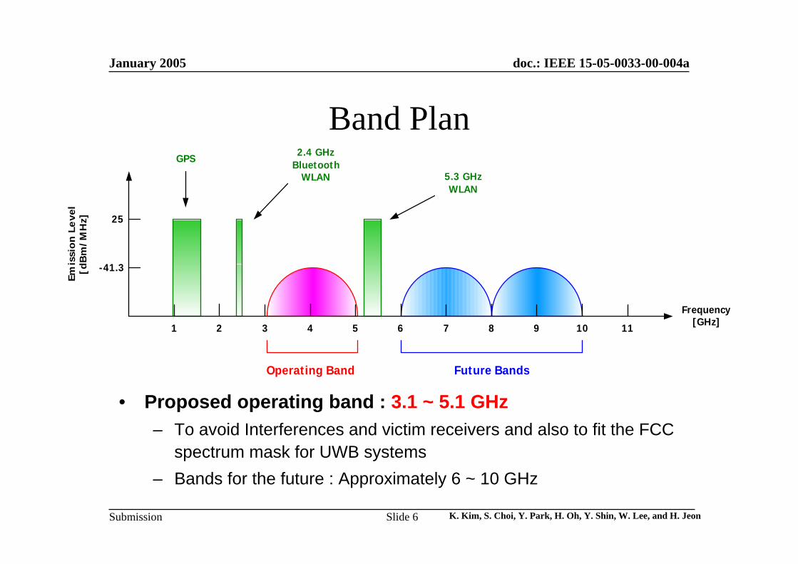
Band Plan
• Proposed operating band : 3.1 ~ 5.1 GHz– To avoid Interferences and victim receivers and also to fit the FCC
spectrum mask for UWB systems– Bands for the future : Approximately 6 ~ 10 GHz
1 2 3 4 5 6 7 8 9 10 11
5.3 GHzWLAN
2.4 GHzBluetooth
WLAN
GPS
25
-41.3
Frequency[GHz]
Emis
sio
n L
eve
l[d
Bm
/MH
z]
Operating Band Future Bands
January 2005
K. Kim, S. Choi, Y. Park, H. Oh, Y. Shin, W. Lee, and H. JeonSlide 7
doc.: IEEE 15-05-0033-00-004a
Submission
Enhanced Noncoherent OOK UWB PHY
January 2005
K. Kim, S. Choi, Y. Park, H. Oh, Y. Shin, W. Lee, and H. JeonSlide 8
doc.: IEEE 15-05-0033-00-004a
Submission
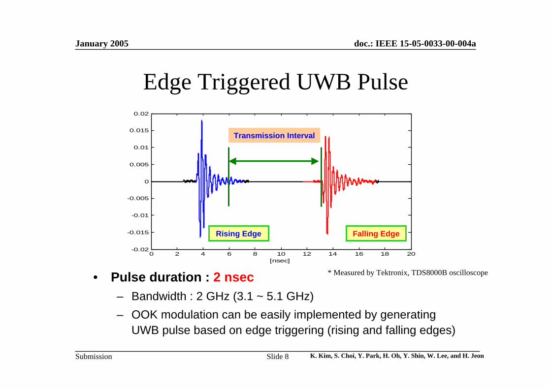
Edge Triggered UWB Pulse
• Pulse duration : 2 nsec– Bandwidth : 2 GHz (3.1 ~ 5.1 GHz)– OOK modulation can be easily implemented by generating
UWB pulse based on edge triggering (rising and falling edges)
0 2 4 6 8 10 12 14 16 18 20-0.02
-0.015
-0.01
-0.005
0
0.005
0.01
0.015
0.02
[nsec]
Rising Edge Falling Edge
Transmission Interval
* Measured by Tektronix, TDS8000B oscilloscope
January 2005
K. Kim, S. Choi, Y. Park, H. Oh, Y. Shin, W. Lee, and H. JeonSlide 9
doc.: IEEE 15-05-0033-00-004a
Submission
0 20 40 60 80 100 120 140 160 180 2000
0.05
0.1
0.15
0.2
0.25
0.3
0.35
0.4
0.45Impuls e res pons e rea lizations
Time (nS )
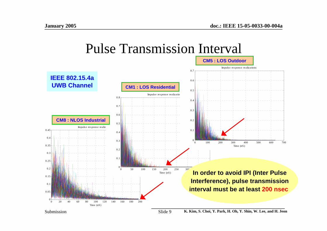
Pulse Transmission Interval
0 50 100 150 200 250 300 350 4000
0.1
0.2
0.3
0.4
0.5
0.6
0.7
0.8Impuls e res pons e realizations
Time (nS )
0 100 200 300 400 500 600 7000
0.1
0.2
0.3
0.4
0.5
0.6
0.7Impuls e res pons e realizations
Time (nS )
CM1 : LOS Residential
CM5 : LOS Outdoor
IEEE 802.15.4aUWB Channel
In order to avoid IPI (Inter PulseInterference), pulse transmissioninterval must be at least 200 nsec
CM8 : NLOS Industrial
January 2005
K. Kim, S. Choi, Y. Park, H. Oh, Y. Shin, W. Lee, and H. JeonSlide 10
doc.: IEEE 15-05-0033-00-004a
Submission
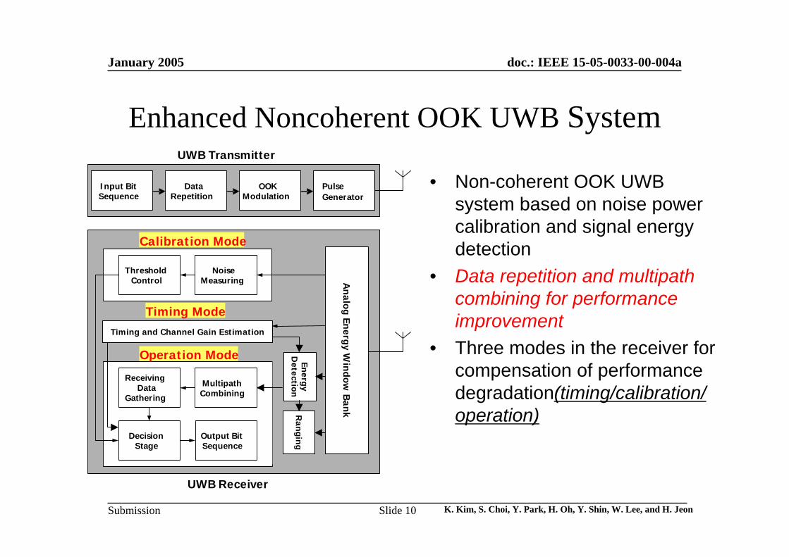
Enhanced Noncoherent OOK UWB System
• Non-coherent OOK UWB system based on noise power calibration and signal energy detection
• Data repetition and multipathcombining for performance improvement
• Three modes in the receiver for compensation of performance degradation(timing/calibration/operation)
Input BitSequence
DataRepetition
OOKModulation
Mod
eSw
itch(
//
)MultipathCombining
ReceivingData
Gathering
Output BitSequence
DecisionStage
UWB Transmitter
Operation Mode
UWB Receiver
Coarse Pulse Position Estimation
Timing Mode
ThresholdControl
NoiseMeasuring
Calibration Mode
nergyD
etection
Timing
Calibration
Operation
PulseGenerator
EEn
ergyD
etectionR
angin
g
An
alog Energy W
indow B
ank
Timing and Channel Gain Estimation
January 2005
K. Kim, S. Choi, Y. Park, H. Oh, Y. Shin, W. Lee, and H. JeonSlide 11
doc.: IEEE 15-05-0033-00-004a
Submission
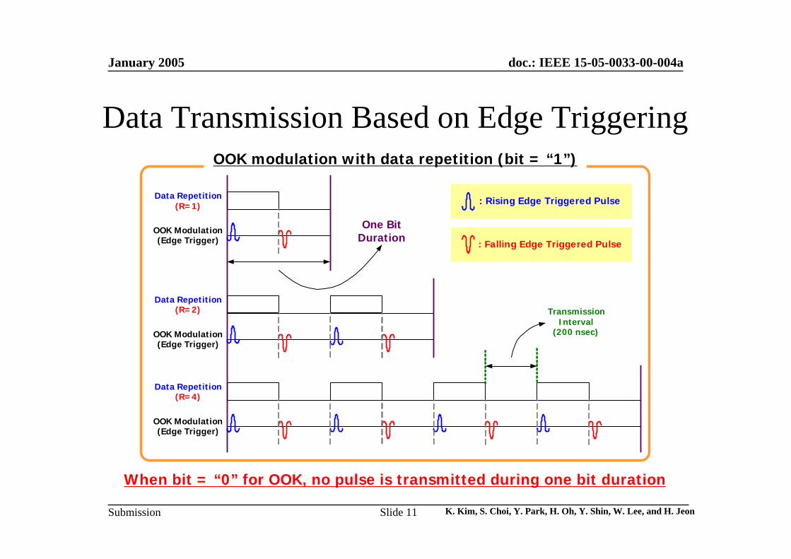
Data Repetition(R=1)
OOK Modulation(Edge Trigger)
: Rising Edge Triggered Pulse
: Falling Edge Triggered Pulse
Data Repetition(R=2)
OOK Modulation(Edge Trigger)
Data Repetition(R=4)
OOK Modulation(Edge Trigger)
TransmissionInterval
(200 nsec)
One BitDuration
Data Transmission Based on Edge TriggeringOOK modulation with data repetition (bit = “1”)
When bit = “0” for OOK, no pulse is transmitted during one bit duration
January 2005
K. Kim, S. Choi, Y. Park, H. Oh, Y. Shin, W. Lee, and H. JeonSlide 12
doc.: IEEE 15-05-0033-00-004a
Submission
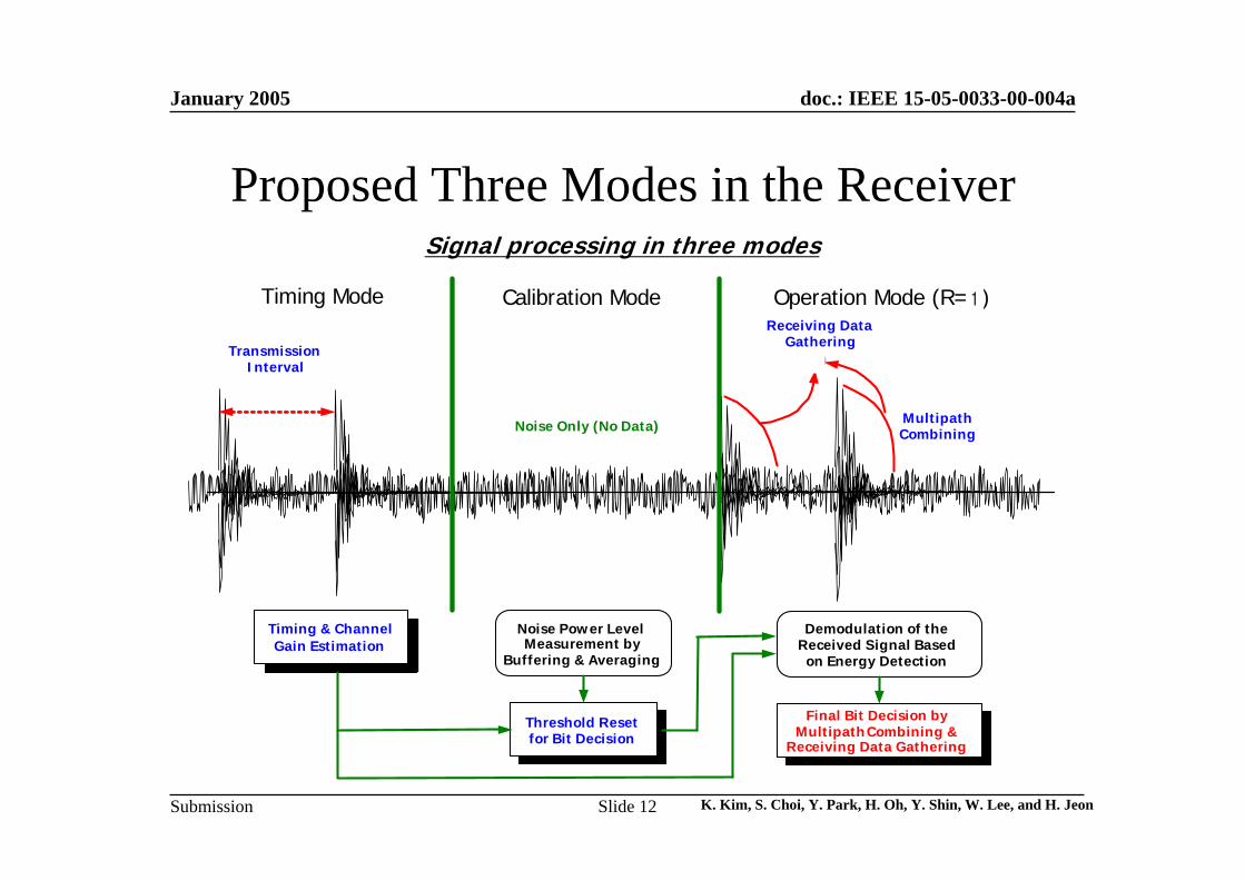
Proposed Three Modes in the ReceiverSignal processing in three modes
Operation Mode (R=2)Calibration Mode
Noise Power LevelMeasurement by
Buffering & Averaging
Threshold Resetfor Bit Decision
Demodulation of theReceived Signal Basedon Energy Detection
Final Bit Decision byMultipathCombining &
Receiving Data Gathering
Noise Only (No Data)
Timing & ChannelGain Estimation
MultipathCombining
Receiving DataGathering
⊕“1” “1” “0”
Timing Mode
TransmissionInterval
PreambleSignal
1
January 2005
K. Kim, S. Choi, Y. Park, H. Oh, Y. Shin, W. Lee, and H. JeonSlide 13
doc.: IEEE 15-05-0033-00-004a
Submission
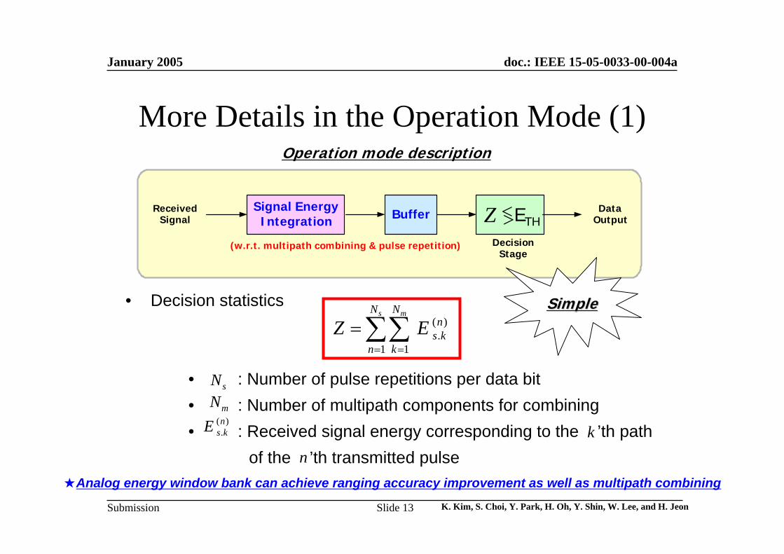
More Details in the Operation Mode (1)Operation mode description
• Decision statistics
• : Number of pulse repetitions per data bit• : Number of multipath components for combining• : Received signal energy corresponding to the ’th path
of the ’th transmitted pulse
sNmN
( ).n
s kE kn
( ).
1 1
s mN Nn
s kn k
Z E= =
= ∑∑
★Analog energy window bank can achieve ranging accuracy improvement as well as multipath combining
Signal EnergyIntegration Z Th<>
ReceivedSignal Buffer
DecisionStage
DataOutput
(w.r.t. multipath combining & pulse repetition)
SimpleSimple
ETH
January 2005
K. Kim, S. Choi, Y. Park, H. Oh, Y. Shin, W. Lee, and H. JeonSlide 14
doc.: IEEE 15-05-0033-00-004a
Submission
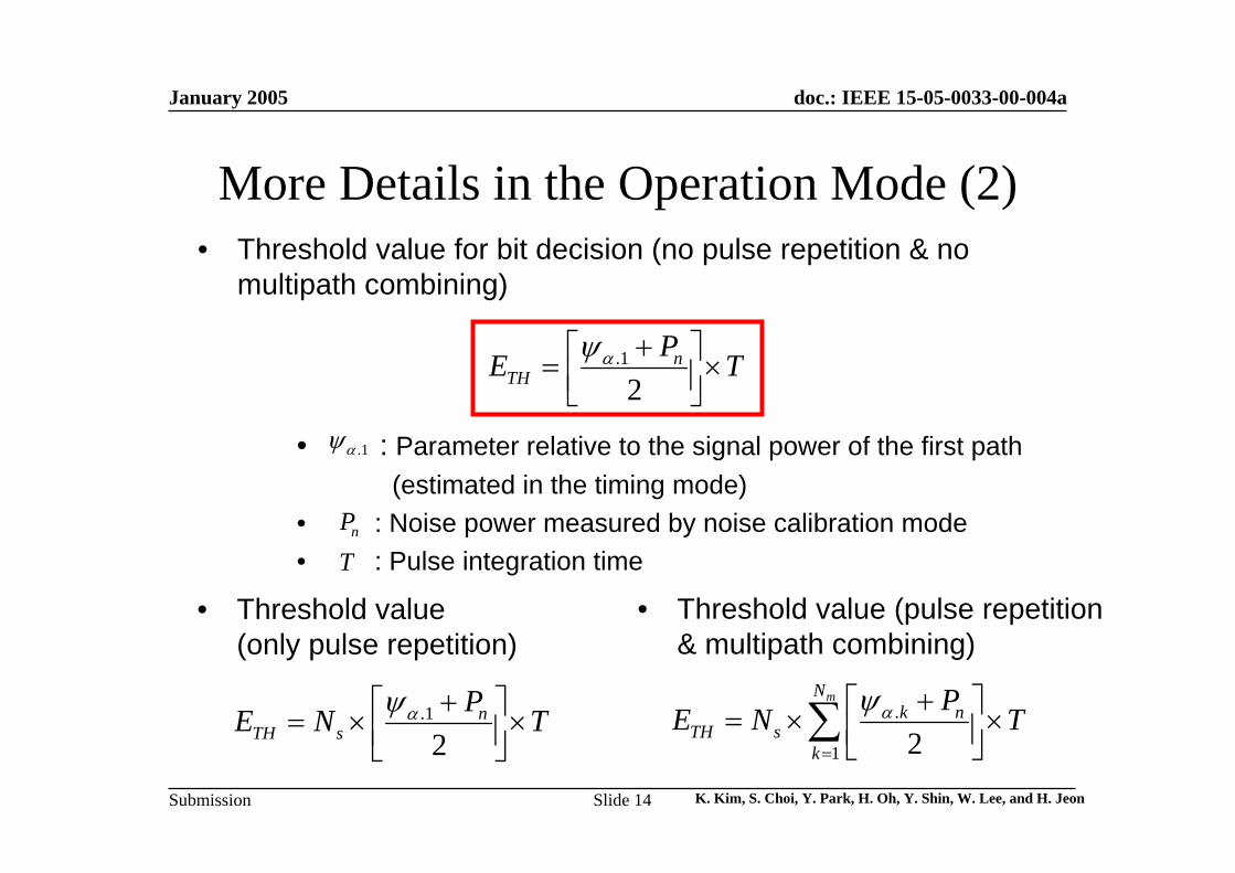
More Details in the Operation Mode (2)• Threshold value for bit decision (no pulse repetition & no
multipath combining)
• : Parameter relative to the signal power of the first path (estimated in the timing mode)
• : Noise power measured by noise calibration mode• : Pulse integration time
.1
2n
THPE Tαψ +⎡ ⎤= ×⎢ ⎥⎣ ⎦
.1αψ
nP
• Threshold value (only pulse repetition)
• Threshold value (pulse repetition & multipath combining)
.1
2n
TH sPE N Tαψ +⎡ ⎤= × ×⎢ ⎥⎣ ⎦
.
1 2
mNk n
TH sk
PE N Tαψ=
+⎡ ⎤= × ×⎢ ⎥⎣ ⎦∑
T
January 2005
K. Kim, S. Choi, Y. Park, H. Oh, Y. Shin, W. Lee, and H. JeonSlide 15
doc.: IEEE 15-05-0033-00-004a
Submission
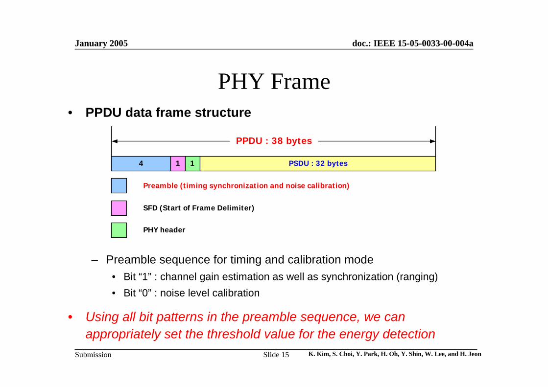
PHY Frame• PPDU data frame structure
– Preamble sequence for timing and calibration mode• Bit “1” : channel gain estimation as well as synchronization (ranging)• Bit “0” : noise level calibration
• Using all bit patterns in the preamble sequence, we can appropriately set the threshold value for the energy detection
4 1 1 PSDU : 32 bytes
Preamble (timing synchronization and noise calibration)
SFD (Start of Frame Delimiter)
PHY header
PPDU : 38 bytes
January 2005
K. Kim, S. Choi, Y. Park, H. Oh, Y. Shin, W. Lee, and H. JeonSlide 16
doc.: IEEE 15-05-0033-00-004a
Submission
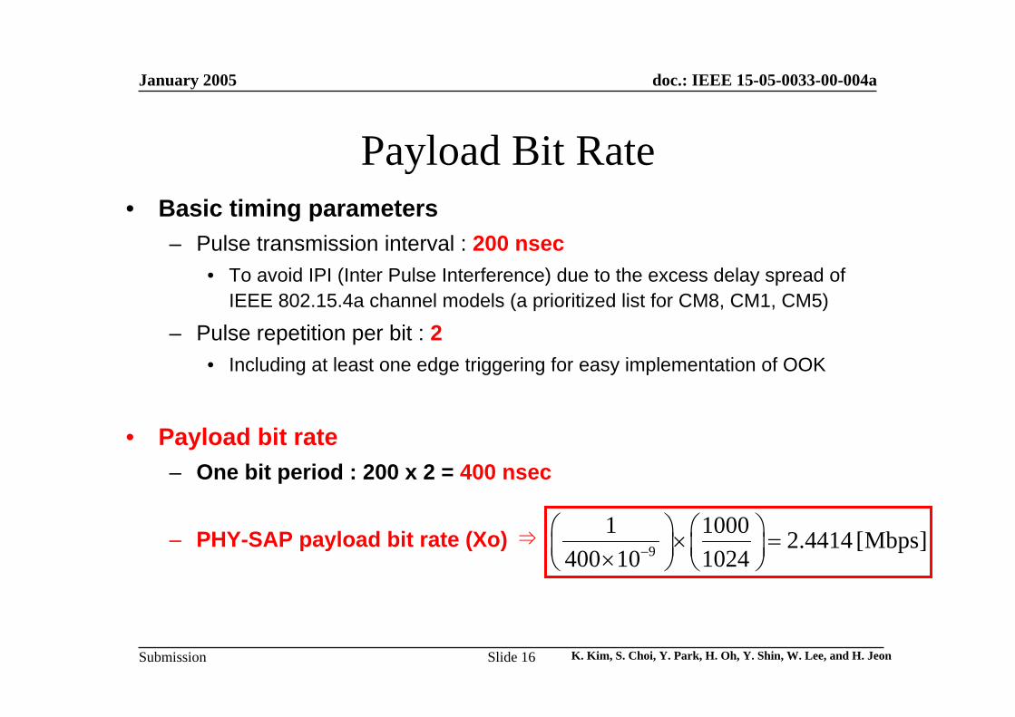
Payload Bit Rate• Basic timing parameters
– Pulse transmission interval : 200 nsec• To avoid IPI (Inter Pulse Interference) due to the excess delay spread of
IEEE 802.15.4a channel models (a prioritized list for CM8, CM1, CM5)
– Pulse repetition per bit : 2• Including at least one edge triggering for easy implementation of OOK
• Payload bit rate– One bit period : 200 x 2 = 400 nsec
– PHY-SAP payload bit rate (Xo) ⇒9
1 1000 2.4414 [Mbps]400 10 1024−
⎛ ⎞ ⎛ ⎞× =⎜ ⎟ ⎜ ⎟×⎝ ⎠ ⎝ ⎠
January 2005
K. Kim, S. Choi, Y. Park, H. Oh, Y. Shin, W. Lee, and H. JeonSlide 17
doc.: IEEE 15-05-0033-00-004a
Submission
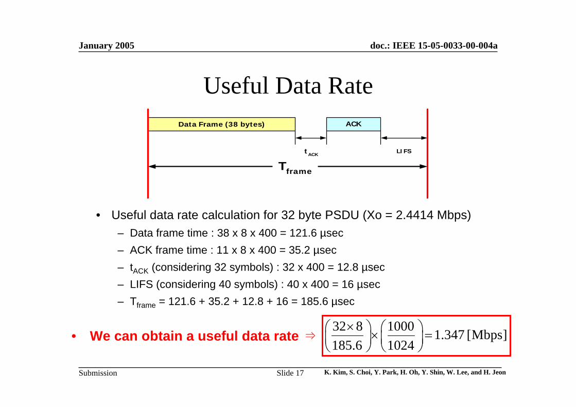
Useful Data Rate
• Useful data rate calculation for 32 byte PSDU (Xo = 2.4414 Mbps)– Data frame time : 38 x 8 x 400 = 121.6 µsec– ACK frame time : 11 x 8 x 400 = 35.2 µsec– tACK (considering 32 symbols) : 32 x 400 = 12.8 µsec– LIFS (considering 40 symbols) : 40 x 400 = 16 µsec– Tframe = 121.6 + 35.2 + 12.8 + 16 = 185.6 µsec
• We can obtain a useful data rate ⇒32 8 1000 1.347 [Mbps]185.6 1024
×⎛ ⎞ ⎛ ⎞× =⎜ ⎟ ⎜ ⎟⎝ ⎠ ⎝ ⎠
LIFStACK
Data Frame (38 bytes) ACK
Tframe
(Time Slot for Multiple Piconet)
January 2005
K. Kim, S. Choi, Y. Park, H. Oh, Y. Shin, W. Lee, and H. JeonSlide 18
doc.: IEEE 15-05-0033-00-004a
Submission
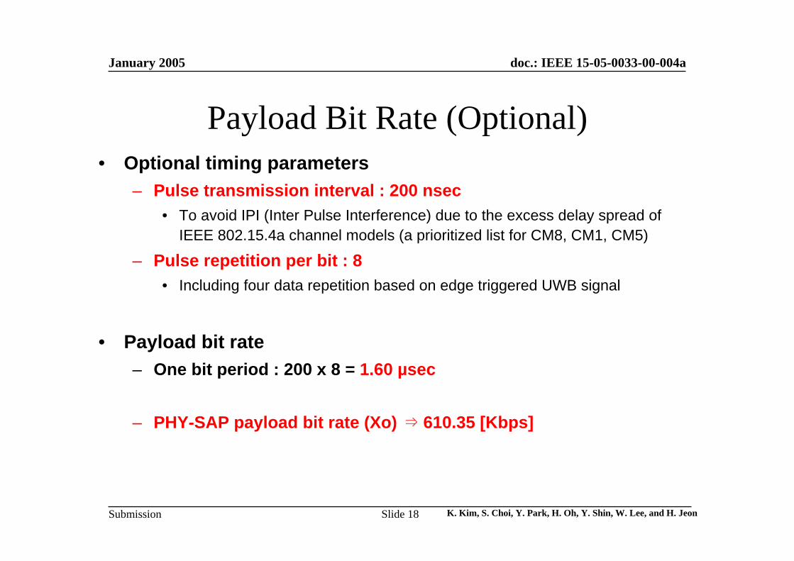
Payload Bit Rate (Optional)• Optional timing parameters
– Pulse transmission interval : 200 nsec• To avoid IPI (Inter Pulse Interference) due to the excess delay spread of
IEEE 802.15.4a channel models (a prioritized list for CM8, CM1, CM5)
– Pulse repetition per bit : 8 • Including four data repetition based on edge triggered UWB signal
• Payload bit rate– One bit period : 200 x 8 = 1.60 µsec
– PHY-SAP payload bit rate (Xo) ⇒ 610.35 [Kbps]
January 2005
K. Kim, S. Choi, Y. Park, H. Oh, Y. Shin, W. Lee, and H. JeonSlide 19
doc.: IEEE 15-05-0033-00-004a
Submission
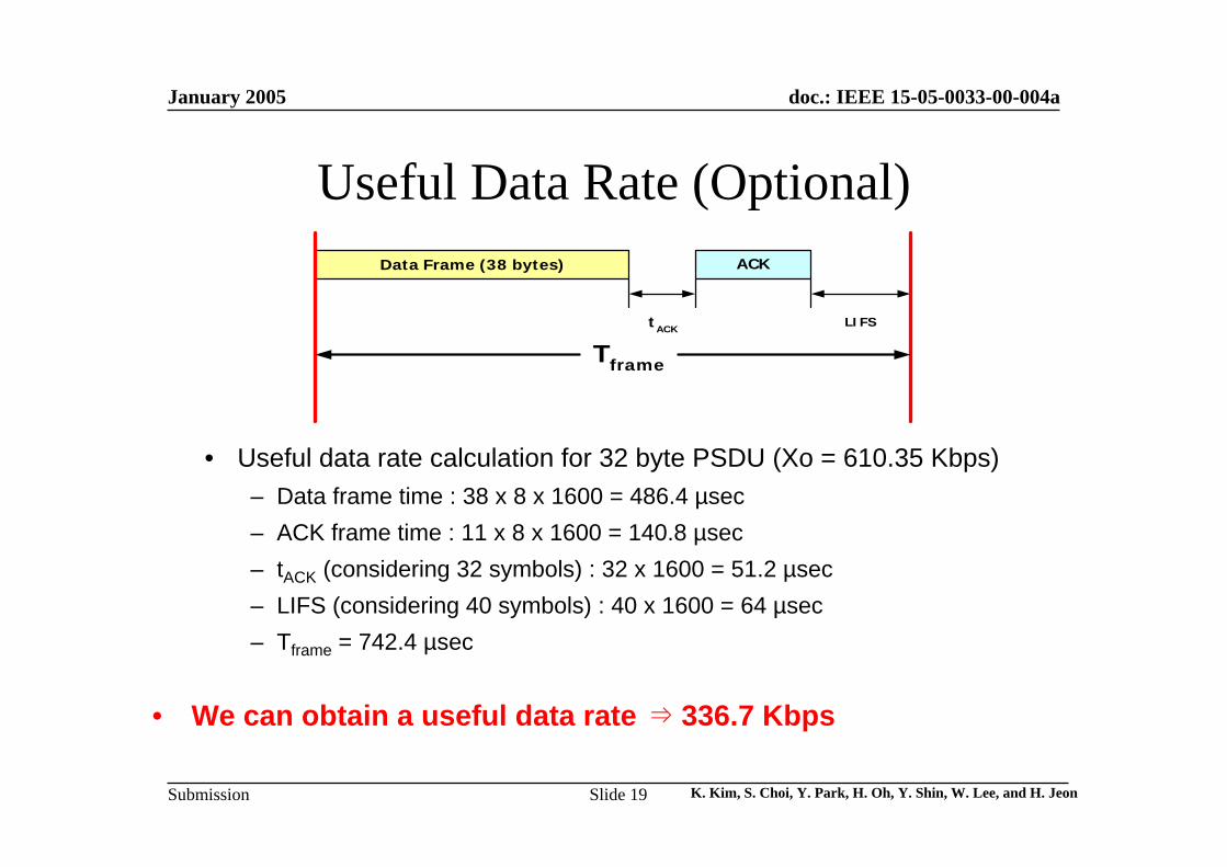
Useful Data Rate (Optional)
• Useful data rate calculation for 32 byte PSDU (Xo = 610.35 Kbps)– Data frame time : 38 x 8 x 1600 = 486.4 µsec– ACK frame time : 11 x 8 x 1600 = 140.8 µsec– tACK (considering 32 symbols) : 32 x 1600 = 51.2 µsec– LIFS (considering 40 symbols) : 40 x 1600 = 64 µsec– Tframe = 742.4 µsec
• We can obtain a useful data rate ⇒ 336.7 Kbps
LIFStACK
Data Frame (38 bytes) ACK
Tframe
(Time Slot for Multiple Piconet)
January 2005
K. Kim, S. Choi, Y. Park, H. Oh, Y. Shin, W. Lee, and H. JeonSlide 20
doc.: IEEE 15-05-0033-00-004a
Submission
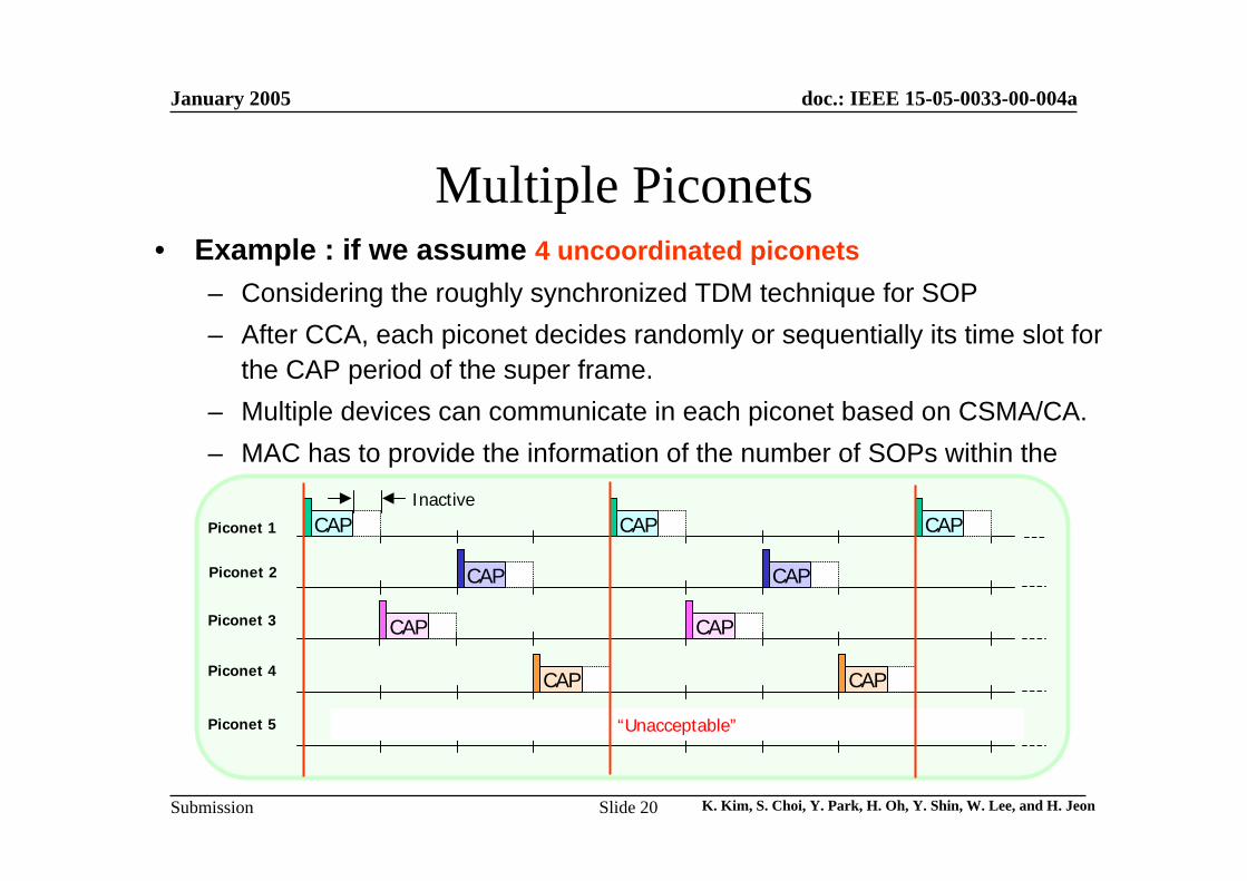
Multiple Piconets• Example : if we assume 4 uncoordinated piconets
– Considering the roughly synchronized TDM technique for SOP– After CCA, each piconet decides randomly or sequentially its time slot for
the CAP period of the super frame.– Multiple devices can communicate in each piconet based on CSMA/CA.– MAC has to provide the information of the number of SOPs within the
beacon payload.CAP CAP CAP
CAP CAP
CAP CAP
CAP CAP
Piconet 1
Piconet 2
Piconet 3
Piconet 4
Piconet 5 “Unacceptable”
Inactive
January 2005
K. Kim, S. Choi, Y. Park, H. Oh, Y. Shin, W. Lee, and H. JeonSlide 21
doc.: IEEE 15-05-0033-00-004a
Submission
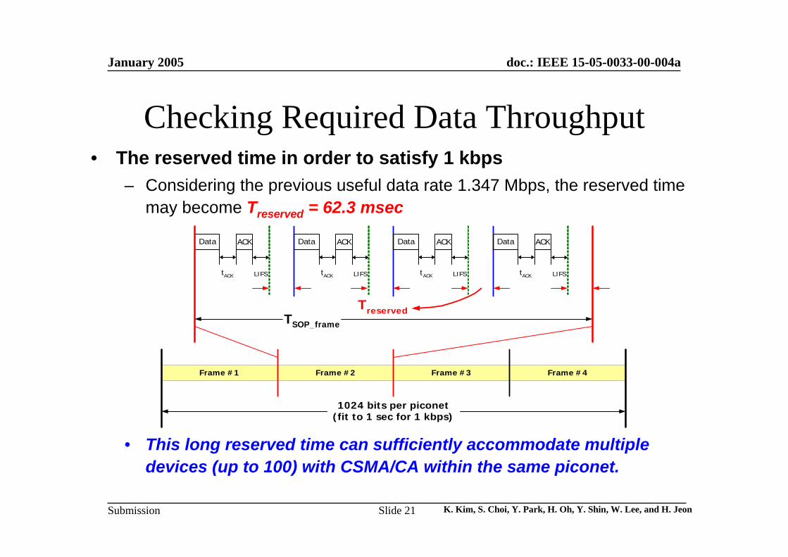
Checking Required Data Throughput• The reserved time in order to satisfy 1 kbps
– Considering the previous useful data rate 1.347 Mbps, the reserved time may become Treserved = 62.3 msec
• This long reserved time can sufficiently accommodate multiple devices (up to 100) with CSMA/CA within the same piconet.
LIFS
Data ACK
Tframe
tACK LIFS
Data ACK
tACK LIFS
Data ACK
tACK LIFS
Data ACK
tACK
Treserved
Frame #1 Frame #2 Frame #3 Frame #4
1024 bits per piconet(fit to 1 sec for 1 kbps)
TSOP_frame
January 2005
K. Kim, S. Choi, Y. Park, H. Oh, Y. Shin, W. Lee, and H. JeonSlide 22
doc.: IEEE 15-05-0033-00-004a
Submission
Ranging and Positioning
January 2005
K. Kim, S. Choi, Y. Park, H. Oh, Y. Shin, W. Lee, and H. JeonSlide 23
doc.: IEEE 15-05-0033-00-004a
Submission
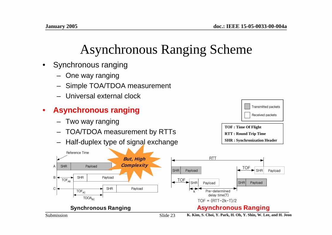
Asynchronous Ranging Scheme• Synchronous ranging
– One way ranging– Simple TOA/TDOA measurement– Universal external clock
• Asynchronous ranging– Two way ranging– TOA/TDOA measurement by RTTs– Half-duplex type of signal exchange
Transmitted packets
Received packets
TOF : Time Of Flight
RTT : Round Trip Time
SHR : Synchronization Header
SHR Payload
SHR Payload
SHR Payload
Reference Time
A
B
C
TOFAB
TOFAC
TDOABC
RTT
TOF
TOF
SHR SHRPayload Payload
Pre-determined delay time(T)
SHR Payload SHR Payload
TOF = (RTT-2k-T)/2
k
Synchronous Ranging Asynchronous Ranging
But, HighComplexity
January 2005
K. Kim, S. Choi, Y. Park, H. Oh, Y. Shin, W. Lee, and H. JeonSlide 24
doc.: IEEE 15-05-0033-00-004a
Submission
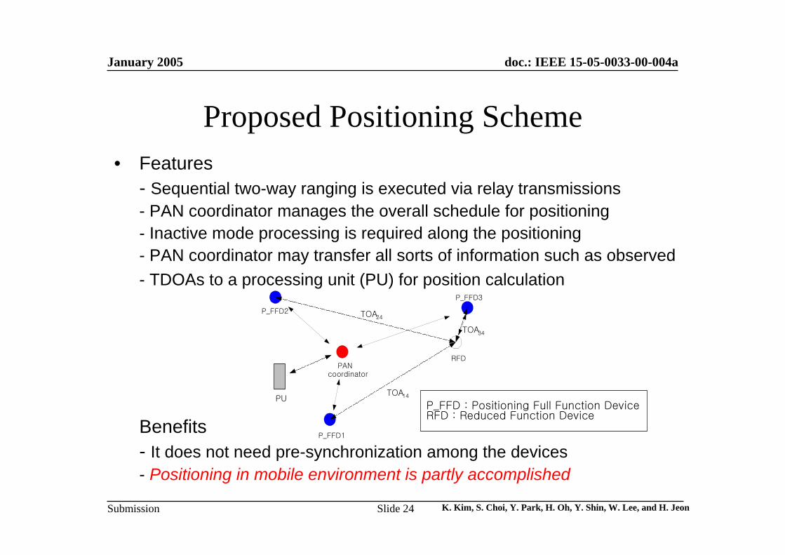
• Features- Sequential two-way ranging is executed via relay transmissions- PAN coordinator manages the overall schedule for positioning- Inactive mode processing is required along the positioning- PAN coordinator may transfer all sorts of information such as observed - TDOAs to a processing unit (PU) for position calculation
Benefits- It does not need pre-synchronization among the devices- Positioning in mobile environment is partly accomplished
PAN coordinator
P_FFD1
P_FFD2
P_FFD3
RFD
TOA14
TOA24
TOA34
P_FFD : Positioning Full Function DeviceRFD : Reduced Function Device
PU
Proposed Positioning Scheme
January 2005
K. Kim, S. Choi, Y. Park, H. Oh, Y. Shin, W. Lee, and H. JeonSlide 25
doc.: IEEE 15-05-0033-00-004a
Submission
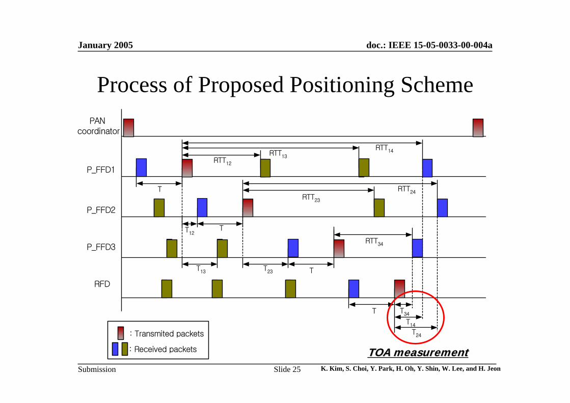
Process of Proposed Positioning SchemePAN
coordinator
P_FFD1
P_FFD2
P_FFD3
RFD
T
T
T
T
RTT12
RTT23
RTT13
RTT14
RTT24
RTT34
T12
T23T13
T14
T34
T24: Transmited packets
: Received packets TOA measurementTOA measurement
January 2005
K. Kim, S. Choi, Y. Park, H. Oh, Y. Shin, W. Lee, and H. JeonSlide 26
doc.: IEEE 15-05-0033-00-004a
Submission
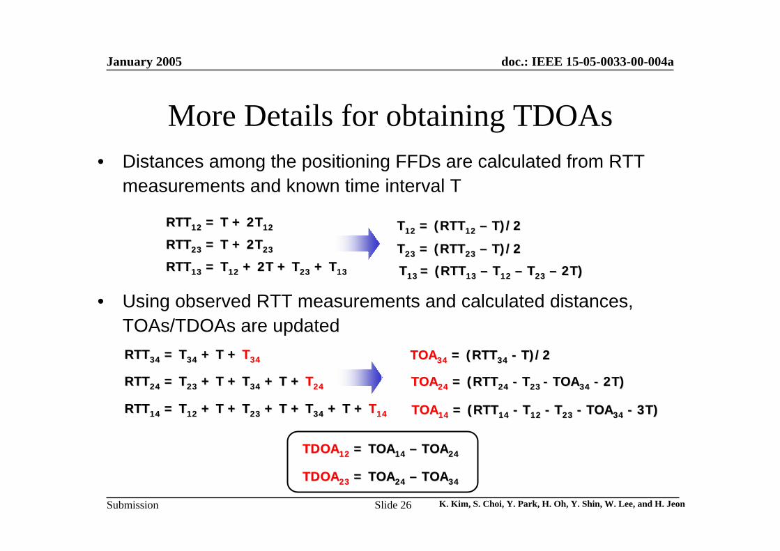
More Details for obtaining TDOAs• Distances among the positioning FFDs are calculated from RTT
measurements and known time interval T
• Using observed RTT measurements and calculated distances, TOAs/TDOAs are updated
RTTRTT1212 = T + 2T= T + 2T1212
RTTRTT2323 = T + 2T= T + 2T2323
RTTRTT1313 = T= T1212 + 2T + T+ 2T + T2323 + T+ T1313
TT1212 = (RTT= (RTT1212 –– T)/2T)/2
TT2323 = (RTT= (RTT2323 –– T)/2T)/2
TT13 13 = (RTT= (RTT1313 –– TT1212 –– TT2323 –– 2T)2T)
RTTRTT3434 = T= T3434 + T + + T + TT3434
RTTRTT1414 = T= T1212 + T + T+ T + T2323 + T + T+ T + T3434 + T + + T + TT1414
RTTRTT2424 = T= T2323 + T + T+ T + T3434 + T + + T + TT2424
TOATOA1414 = (RTT= (RTT1414 -- TT1212 -- TT2323 -- TOATOA3434 -- 3T)3T)
TOATOA3434 = (RTT= (RTT3434 -- T)/2T)/2
TOATOA2424 = (RTT= (RTT2424 -- TT23 23 -- TOATOA3434 -- 2T)2T)
TDOATDOA1212 = TOA= TOA1414 –– TOATOA2424
TDOATDOA2323 = TOA= TOA2424 –– TOATOA3434
January 2005
K. Kim, S. Choi, Y. Park, H. Oh, Y. Shin, W. Lee, and H. JeonSlide 27
doc.: IEEE 15-05-0033-00-004a
Submission
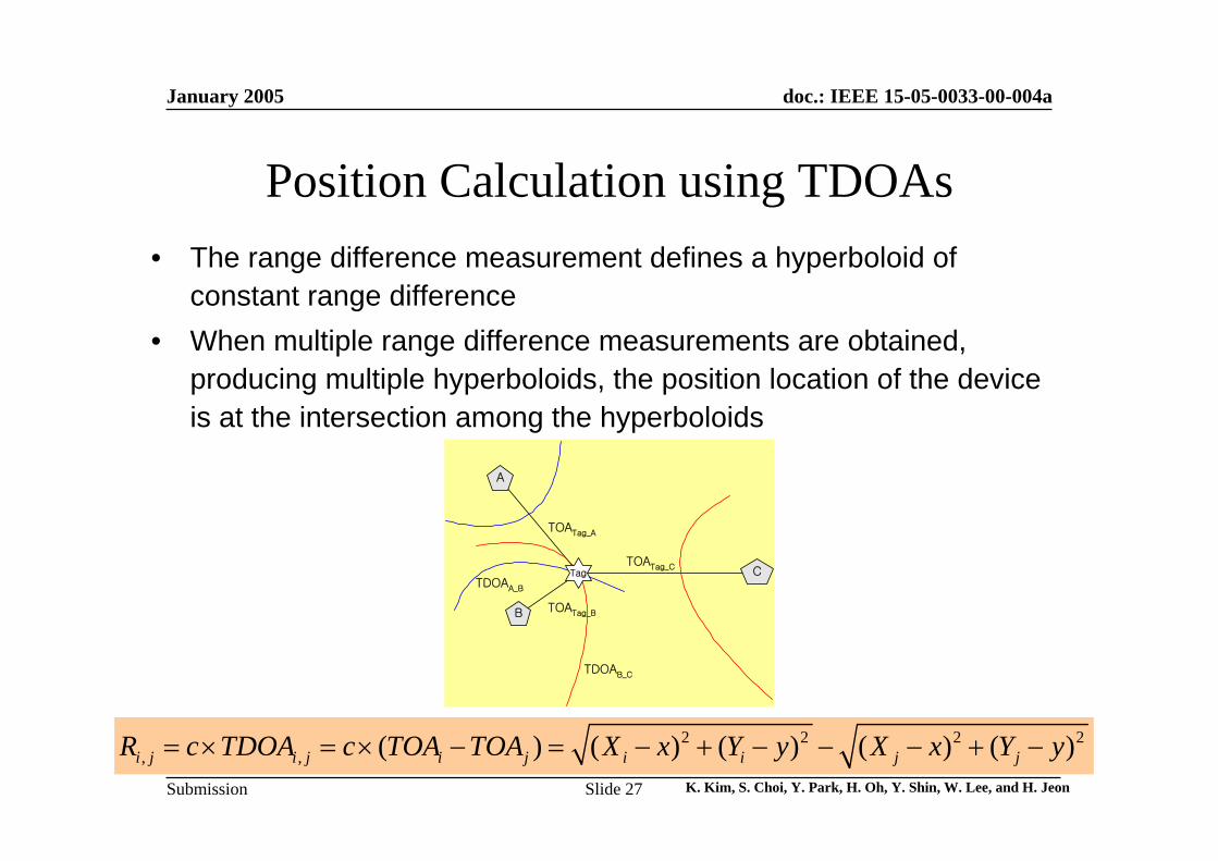
Position Calculation using TDOAs• The range difference measurement defines a hyperboloid of
constant range difference • When multiple range difference measurements are obtained,
producing multiple hyperboloids, the position location of the device is at the intersection among the hyperboloids
2 2 2 2, , ( ) ( ) ( ) ( ) ( )i j i j i j i i j jR c TDOA c TOA TOA X x Y y X x Y y= × = × − = − + − − − + −
A
B
C
TOATag_A
TOATag_B
TOATag_CTag
TDOAB_C
TDOAA_B
January 2005
K. Kim, S. Choi, Y. Park, H. Oh, Y. Shin, W. Lee, and H. JeonSlide 28
doc.: IEEE 15-05-0033-00-004a
Submission
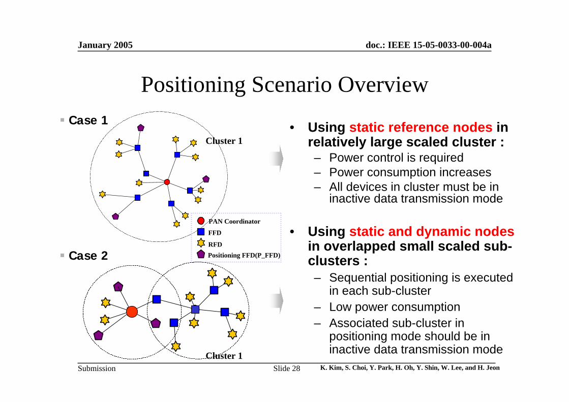
Positioning Scenario Overview
Cluster 1
Cluster 1
Case 1
Case 2
PAN Coordinator
FFD
RFDPositioning FFD(P_FFD)
• Using static reference nodes in relatively large scaled cluster :– Power control is required– Power consumption increases– All devices in cluster must be in
inactive data transmission mode
• Using static and dynamic nodesin overlapped small scaled sub-clusters :– Sequential positioning is executed
in each sub-cluster– Low power consumption– Associated sub-cluster in
positioning mode should be in inactive data transmission mode
January 2005
K. Kim, S. Choi, Y. Park, H. Oh, Y. Shin, W. Lee, and H. JeonSlide 29
doc.: IEEE 15-05-0033-00-004a
Submission
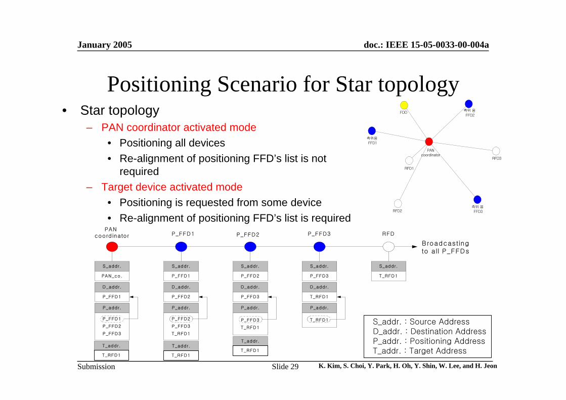
Positioning Scenario for Star topology• Star topology
– PAN coordinator activated mode• Positioning all devices• Re-alignment of positioning FFD’s list is not
required – Target device activated mode
• Positioning is requested from some device• Re-alignment of positioning FFD’s list is required
S_addr. : Source AddressD_addr. : Destination AddressP_addr. : Positioning AddressT_addr. : Target Address
PAN coordinator P_FFD2P_FFD1 P_FFD3 RFD
S_addr.
PAN_co.
D_addr.
P_FFD1
P_addr.
P_FFD1
P_FFD2
P_FFD3
S_addr.
P_FFD1
D_addr.
P_FFD2
P_addr.
P_FFD2
P_FFD3
T_RFD1
S_addr.
P_FFD2
D_addr.
P_FFD3
P_addr.
P_FFD3
T_RFD1
S_addr.
P_FFD3
D_addr.
T_RFD1
S_addr.
T_RFD1
P_addr.
T_RFD1
Broadcastingto all P_FFDs
T_addr.
T_RFD1
T_addr.
T_RFD1
T_addr.
T_RFD1
FDD 측위 용 FFD2
측위용 FFD1
RFD1
PANcoordinator
측위 용 FFD3
RFD3
RFD2
January 2005
K. Kim, S. Choi, Y. Park, H. Oh, Y. Shin, W. Lee, and H. JeonSlide 30
doc.: IEEE 15-05-0033-00-004a
Submission
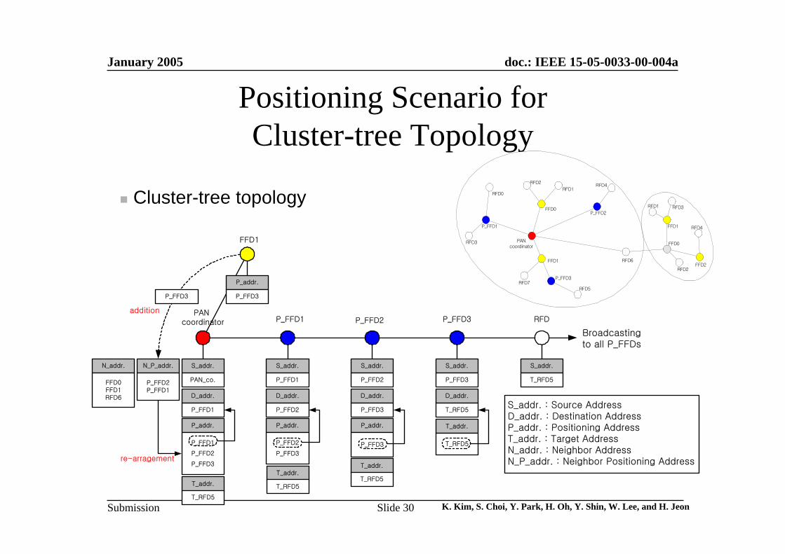
Positioning Scenario for Cluster-tree Topology
P_FFD1
RFD3
RFD0
RFD2
RFD1
FFD0
PANcoordinator
P_FFD3
RFD5
P_FFD2
RFD4
RFD1 RFD3
FFD1
FFD0
RFD2FFD2
RFD4
RFD6
RFD7
FFD1
Cluster-tree topology
PAN coordinator P_FFD2P_FFD1 P_FFD3 RFD
S_addr.
PAN_co.
D_addr.
P_FFD1
P_addr.
P_FFD1
P_FFD2
P_FFD3
S_addr.
P_FFD1
D_addr.
P_FFD2
P_addr.
P_FFD2
P_FFD3
S_addr.
P_FFD2
D_addr.
P_FFD3
P_addr.
P_FFD3
S_addr.
P_FFD3
D_addr.
T_RFD5
S_addr.
T_RFD5
T_addr.
T_RFD5
Broadcastingto all P_FFDs
N_P_addr.
P_FFD2P_FFD1
re-arragement
N_addr.
FFD0FFD1RFD6
S_addr. : Source AddressD_addr. : Destination AddressP_addr. : Positioning AddressT_addr. : Target AddressN_addr. : Neighbor AddressN_P_addr. : Neighbor Positioning Address
FFD1
P_FFD3
addition
P_addr.
P_FFD3
T_addr.
T_RFD5
T_addr.
T_RFD5
T_addr.
T_RFD5

January 2005
K. Kim, S. Choi, Y. Park, H. Oh, Y. Shin, W. Lee, and H. JeonSlide 31
doc.: IEEE 15-05-0033-00-004a
Submission
Modifying MAC
January 2005
K. Kim, S. Choi, Y. Park, H. Oh, Y. Shin, W. Lee, and H. JeonSlide 32
doc.: IEEE 15-05-0033-00-004a
Submission
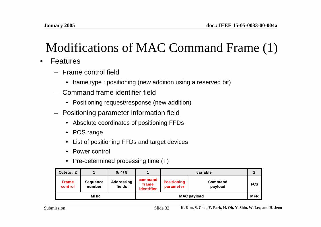
Modifications of MAC Command Frame (1)• Features
– Frame control field• frame type : positioning (new addition using a reserved bit)
– Command frame identifier field• Positioning request/response (new addition)
– Positioning parameter information field• Absolute coordinates of positioning FFDs • POS range• List of positioning FFDs and target devices• Power control • Pre-determined processing time (T)
MFRMFR
FCSFCS
22
CommandCommandpayloadpayload
Positioning parameter
command frame
identifier
AddressingAddressingfieldsfields
SequenceSequencenumbernumber
Framecontrol
MAC payloadMAC payloadMHRMHR
variablevariable110/4/80/4/811Octets : 2Octets : 2
January 2005
K. Kim, S. Choi, Y. Park, H. Oh, Y. Shin, W. Lee, and H. JeonSlide 33
doc.: IEEE 15-05-0033-00-004a
Submission
Modifications of MAC Command Frame (2)
ReservedReserved00x0c~0xffx0c~0xff
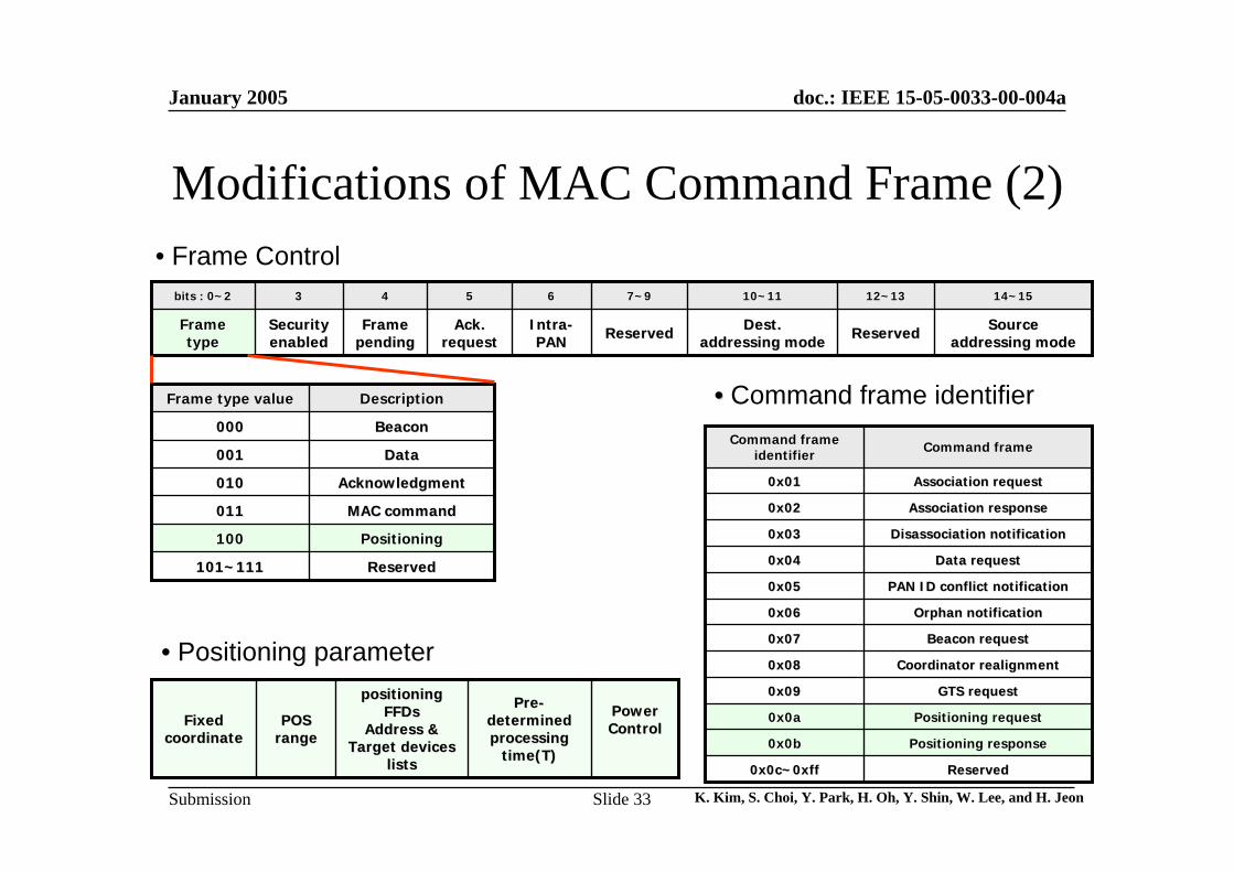
Positioning responsePositioning response00x0bx0b
Positioning requestPositioning request00x0ax0a
Association responseAssociation response00x02x02
Association requestAssociation request00x01x01
GTS requestGTS request00x09x09
Beacon requestBeacon request00x07x07
PAN ID conflict notificationPAN ID conflict notification00x05x05
Disassociation notificationDisassociation notification00x03x03
Coordinator realignmentCoordinator realignment00x08x08
Orphan notificationOrphan notification00x06x06
Data requestData request00x04x04
Command frameCommand frameCommand frameCommand frameidentifieridentifier
ReservedReserved
12~1312~13
ReservedReserved
7~97~9
AckAck..requestrequest
55
SecuritySecurityenabledenabled
33
SourceSourceaddressing modeaddressing mode
DestDest..addressing modeaddressing mode
IntraIntra--PANPAN
FrameFramependingpending
FrameFrametypetype
14~1514~1510~1110~116644bits : 0~2bits : 0~2
PositioningPositioning100100
AcknowledgmentAcknowledgment010010
BeaconBeacon000000
ReservedReserved101~111101~111
MAC commandMAC command011011
DataData001001
DescriptionDescriptionFrame type valueFrame type value
• Frame Control
•• Command frame identifier
• Positioning parameter
Power Power ControlControl
PrePre--determined determined processing processing
time(T)time(T)
positioning positioning FFDsFFDs
Address & Address & Target devices Target devices
listslists
POSPOSrangerange
FixedFixedcoordinatecoordinate

January 2005
K. Kim, S. Choi, Y. Park, H. Oh, Y. Shin, W. Lee, and H. JeonSlide 34
doc.: IEEE 15-05-0033-00-004a
Submission
Analog Energy Window Bank
January 2005
K. Kim, S. Choi, Y. Park, H. Oh, Y. Shin, W. Lee, and H. JeonSlide 35
doc.: IEEE 15-05-0033-00-004a
Submission
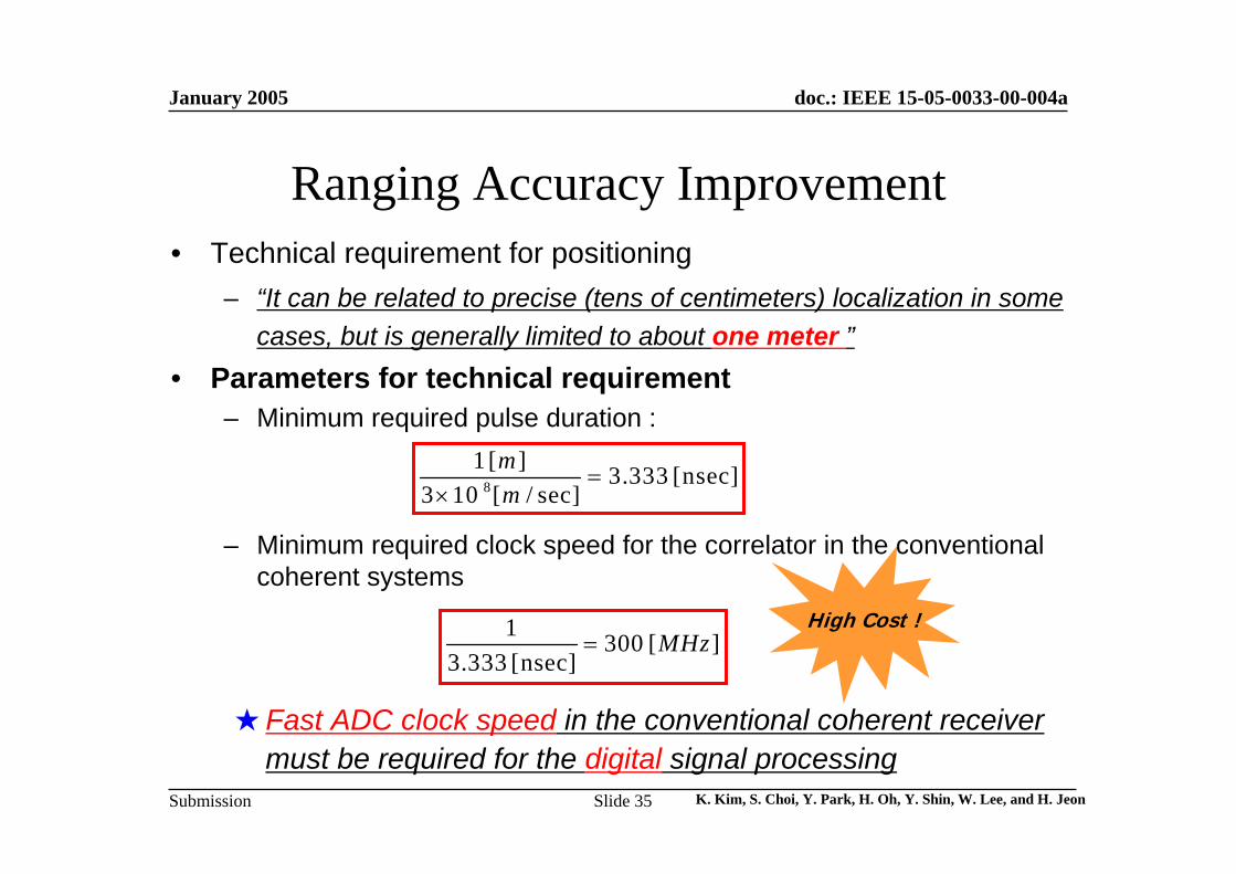
Ranging Accuracy Improvement• Technical requirement for positioning
– “It can be related to precise (tens of centimeters) localization in some cases, but is generally limited to about one meter ”
• Parameters for technical requirement– Minimum required pulse duration :
– Minimum required clock speed for the correlator in the conventional coherent systems
8
1 [ ] 3.333 [nsec]3 10 [ / sec]
mm
=×
1 300 [ ]3.333 [nsec]
MHz=
★Fast ADC clock speed in the conventional coherent receiver must be required for the digital signal processing
High Cost !
January 2005
K. Kim, S. Choi, Y. Park, H. Oh, Y. Shin, W. Lee, and H. JeonSlide 36
doc.: IEEE 15-05-0033-00-004a
Submission
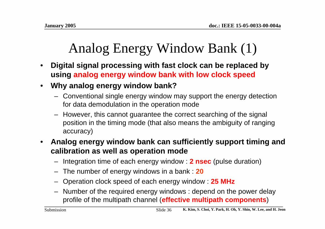
Analog Energy Window Bank (1)• Digital signal processing with fast clock can be replaced by
using analog energy window bank with low clock speed• Why analog energy window bank?
– Conventional single energy window may support the energy detection for data demodulation in the operation mode
– However, this cannot guarantee the correct searching of the signal position in the timing mode (that also means the ambiguity of ranging accuracy)
• Analog energy window bank can sufficiently support timing and calibration as well as operation mode – Integration time of each energy window : 2 nsec (pulse duration)– The number of energy windows in a bank : 20– Operation clock speed of each energy window : 25 MHz– Number of the required energy windows : depend on the power delay
profile of the multipath channel (effective multipath components)
January 2005
K. Kim, S. Choi, Y. Park, H. Oh, Y. Shin, W. Lee, and H. JeonSlide 37
doc.: IEEE 15-05-0033-00-004a
Submission
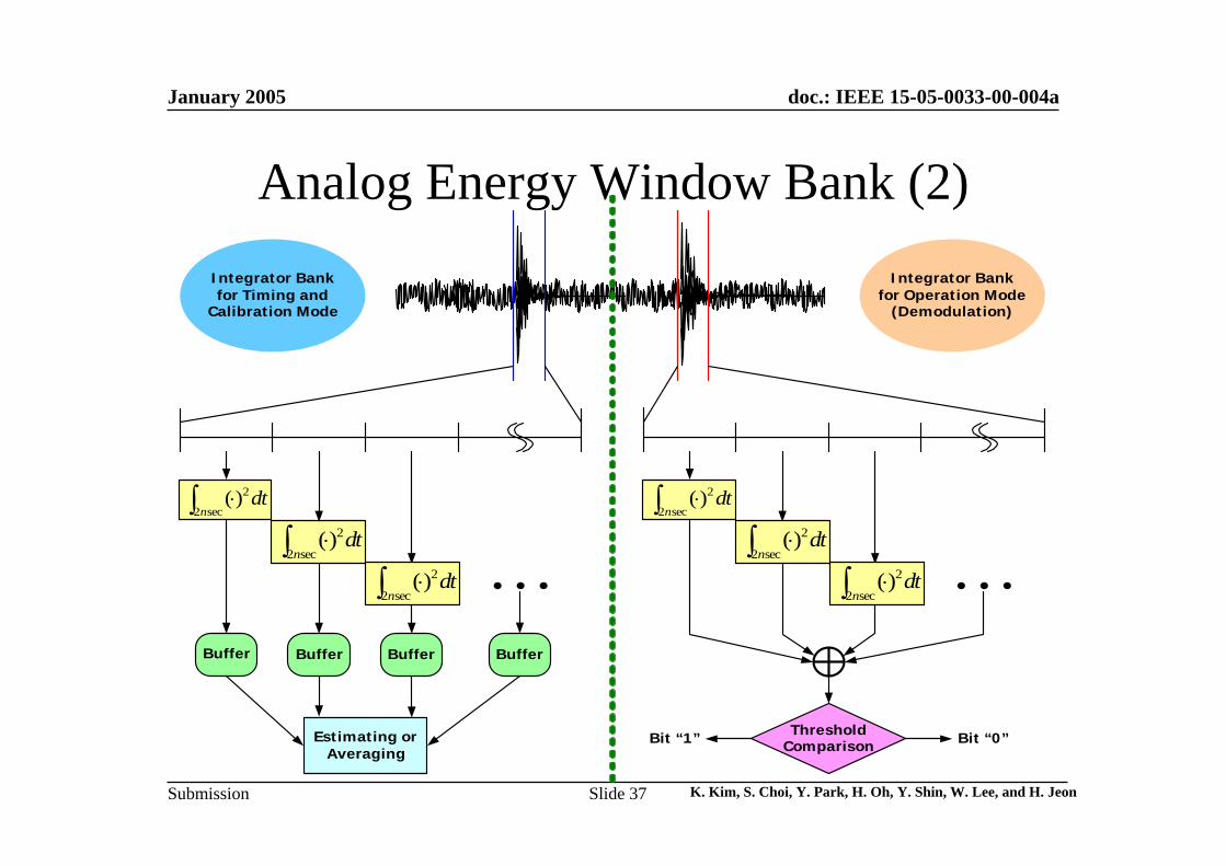
Analog Energy Window Bank (2)
2
2 sec( )
ndt⋅∫
2
2 sec( )
ndt⋅∫
L L
Integrator Bankfor Timing and
Calibration Mode
Integrator Bankfor Operation Mode
(Demodulation)
ThresholdComparisonBit “1” Bit “0”
Buffer Buffer Buffer Buffer
Estimating orAveraging
2
2 sec( )
ndt⋅∫
2
2 sec( )
ndt⋅∫
2
2 sec( )
ndt⋅∫
2
2 sec( )
ndt⋅∫
January 2005
K. Kim, S. Choi, Y. Park, H. Oh, Y. Shin, W. Lee, and H. JeonSlide 38
doc.: IEEE 15-05-0033-00-004a
Submission
Simulation Results
January 2005
K. Kim, S. Choi, Y. Park, H. Oh, Y. Shin, W. Lee, and H. JeonSlide 39
doc.: IEEE 15-05-0033-00-004a
Submission
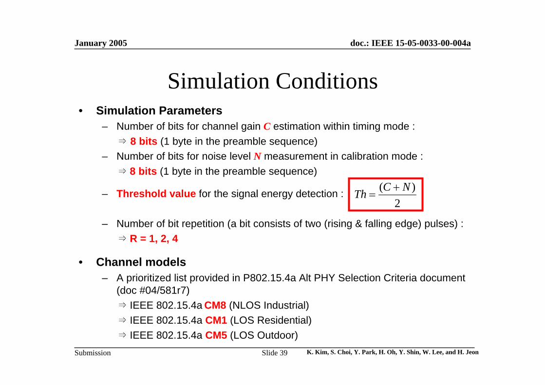
Simulation Conditions• Simulation Parameters
– Number of bits for channel gain C estimation within timing mode : ⇒ 8 bits (1 byte in the preamble sequence)
– Number of bits for noise level N measurement in calibration mode : ⇒ 8 bits (1 byte in the preamble sequence)
– Threshold value for the signal energy detection :
– Number of bit repetition (a bit consists of two (rising & falling edge) pulses) : ⇒ R = 1, 2, 4
• Channel models – A prioritized list provided in P802.15.4a Alt PHY Selection Criteria document
(doc #04/581r7) ⇒ IEEE 802.15.4a CM8 (NLOS Industrial)⇒ IEEE 802.15.4a CM1 (LOS Residential)⇒ IEEE 802.15.4a CM5 (LOS Outdoor)
( )2
C NTh +=
January 2005
K. Kim, S. Choi, Y. Park, H. Oh, Y. Shin, W. Lee, and H. JeonSlide 40
doc.: IEEE 15-05-0033-00-004a
Submission
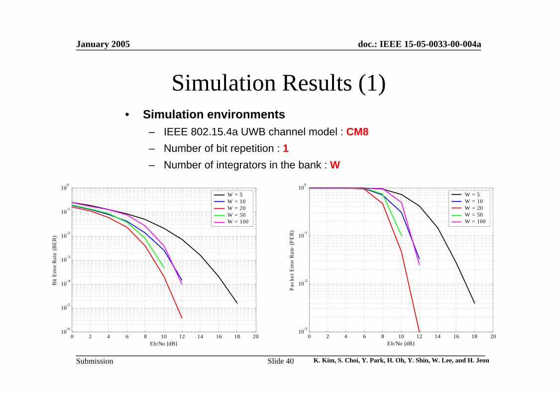
Simulation Results (1)
0 2 4 6 8 10 12 14 16 18 2010
-6
10-5
10-4
10-3
10-2
10-1
100
Bit
Erro
r Rat
e (B
ER
)
Eb/No [dB]
W = 5W = 10W = 20W = 50W = 100
0 2 4 6 8 10 12 14 16 18 2010
-3
10-2
10-1
100
Pac
ket E
rror R
ate
(PE
R)
Eb/No [dB]
W = 5W = 10W = 20W = 50W = 100
• Simulation environments– IEEE 802.15.4a UWB channel model : CM8– Number of bit repetition : 1– Number of integrators in the bank : W
January 2005
K. Kim, S. Choi, Y. Park, H. Oh, Y. Shin, W. Lee, and H. JeonSlide 41
doc.: IEEE 15-05-0033-00-004a
Submission
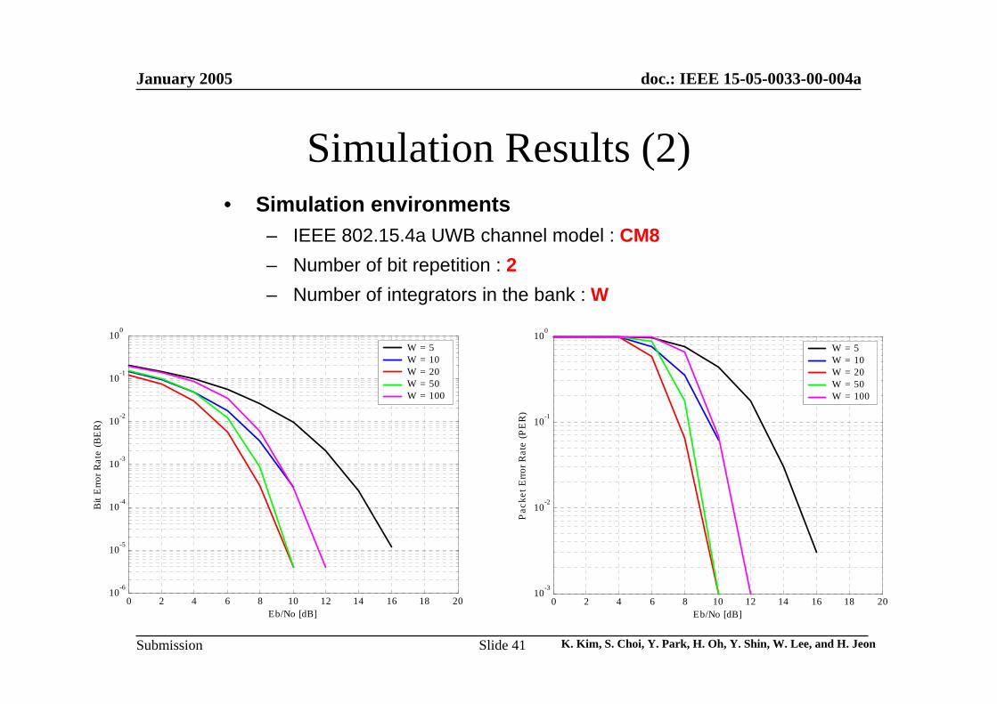
Simulation Results (2)
0 2 4 6 8 10 12 14 16 18 2010
-6
10-5
10-4
10-3
10-2
10-1
100
Bit
Erro
r Rat
e (B
ER
)
Eb/No [dB]
W = 5W = 10W = 20W = 50W = 100
0 2 4 6 8 10 12 14 16 18 2010
-3
10-2
10-1
100
Pac
ket E
rror R
ate
(PE
R)
Eb/No [dB]
W = 5W = 10W = 20W = 50W = 100
• Simulation environments– IEEE 802.15.4a UWB channel model : CM8– Number of bit repetition : 2– Number of integrators in the bank : W
January 2005
K. Kim, S. Choi, Y. Park, H. Oh, Y. Shin, W. Lee, and H. JeonSlide 42
doc.: IEEE 15-05-0033-00-004a
Submission
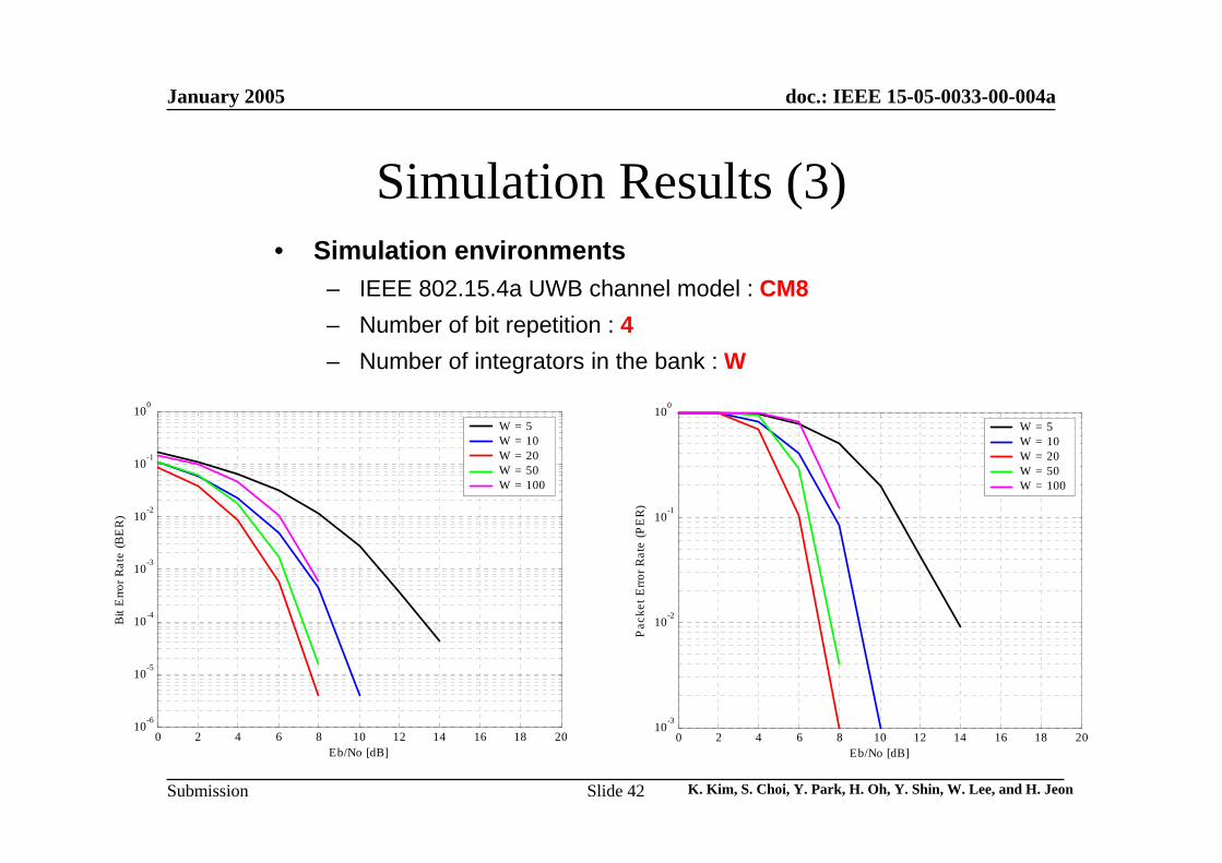
Simulation Results (3)
0 2 4 6 8 10 12 14 16 18 2010
-6
10-5
10-4
10-3
10-2
10-1
100
Bit
Erro
r Rat
e (B
ER
)
Eb/No [dB]
W = 5W = 10W = 20W = 50W = 100
0 2 4 6 8 10 12 14 16 18 2010
-3
10-2
10-1
100
Pac
ket E
rror R
ate
(PE
R)
Eb/No [dB]
W = 5W = 10W = 20W = 50W = 100
• Simulation environments– IEEE 802.15.4a UWB channel model : CM8– Number of bit repetition : 4– Number of integrators in the bank : W
January 2005
K. Kim, S. Choi, Y. Park, H. Oh, Y. Shin, W. Lee, and H. JeonSlide 43
doc.: IEEE 15-05-0033-00-004a
Submission
0 2 4 6 8 10 12 14 16 18 2010
-6
10-5
10-4
10-3
10-2
10-1
100
Bit
Erro
r Rat
e (B
ER
)
Eb/No [dB]
W = 5W = 10W = 20W = 50W = 100
0 2 4 6 8 10 12 14 16 18 2010
-3
10-2
10-1
100
Pac
ket E
rror R
ate
(PE
R)
Eb/No [dB]
W = 5W = 10W = 20W = 50W = 100
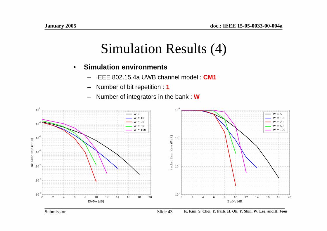
Simulation Results (4)• Simulation environments
– IEEE 802.15.4a UWB channel model : CM1– Number of bit repetition : 1– Number of integrators in the bank : W
January 2005
K. Kim, S. Choi, Y. Park, H. Oh, Y. Shin, W. Lee, and H. JeonSlide 44
doc.: IEEE 15-05-0033-00-004a
Submission
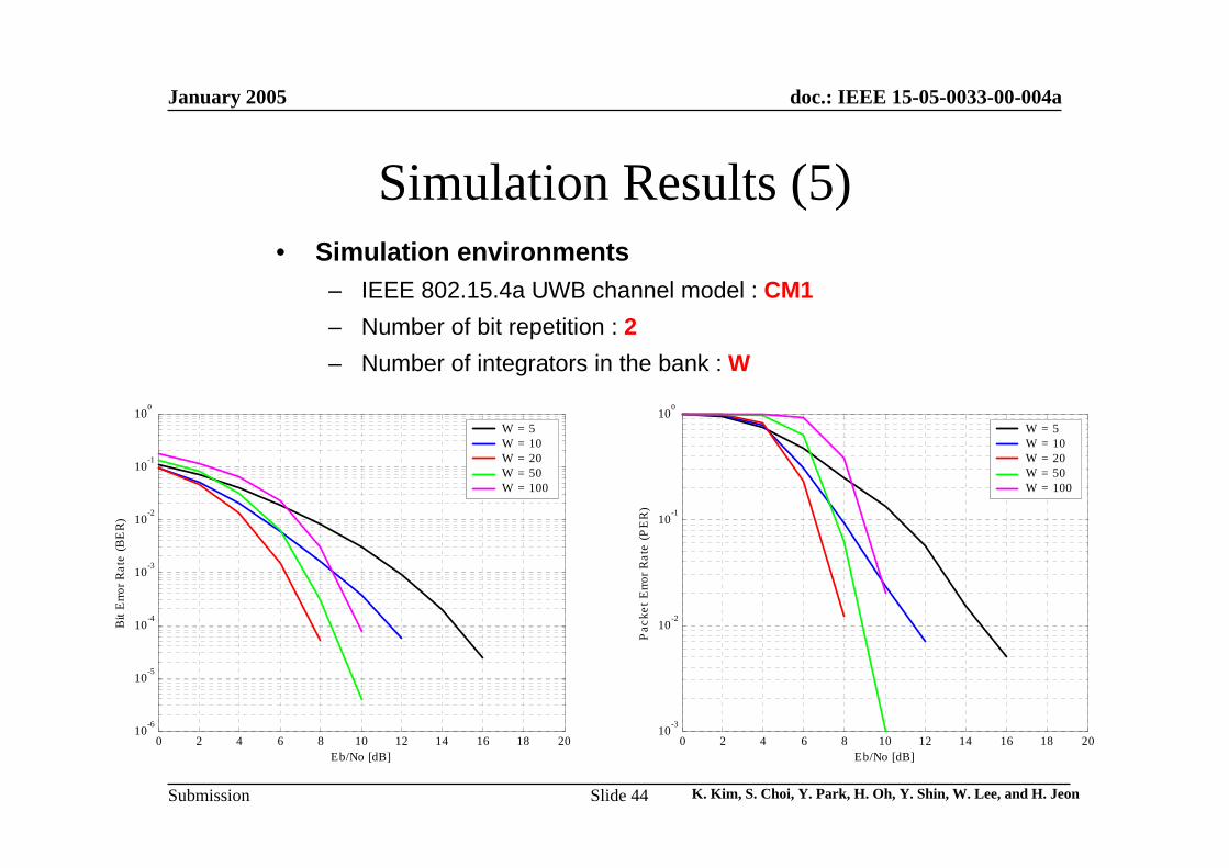
Simulation Results (5)
0 2 4 6 8 10 12 14 16 18 2010
-6
10-5
10-4
10-3
10-2
10-1
100
Bit
Erro
r Rat
e (B
ER
)
Eb/No [dB]
W = 5W = 10W = 20W = 50W = 100
0 2 4 6 8 10 12 14 16 18 2010
-3
10-2
10-1
100
Pac
ket E
rror R
ate
(PE
R)
Eb/No [dB]
W = 5W = 10W = 20W = 50W = 100
• Simulation environments– IEEE 802.15.4a UWB channel model : CM1– Number of bit repetition : 2– Number of integrators in the bank : W
January 2005
K. Kim, S. Choi, Y. Park, H. Oh, Y. Shin, W. Lee, and H. JeonSlide 45
doc.: IEEE 15-05-0033-00-004a
Submission
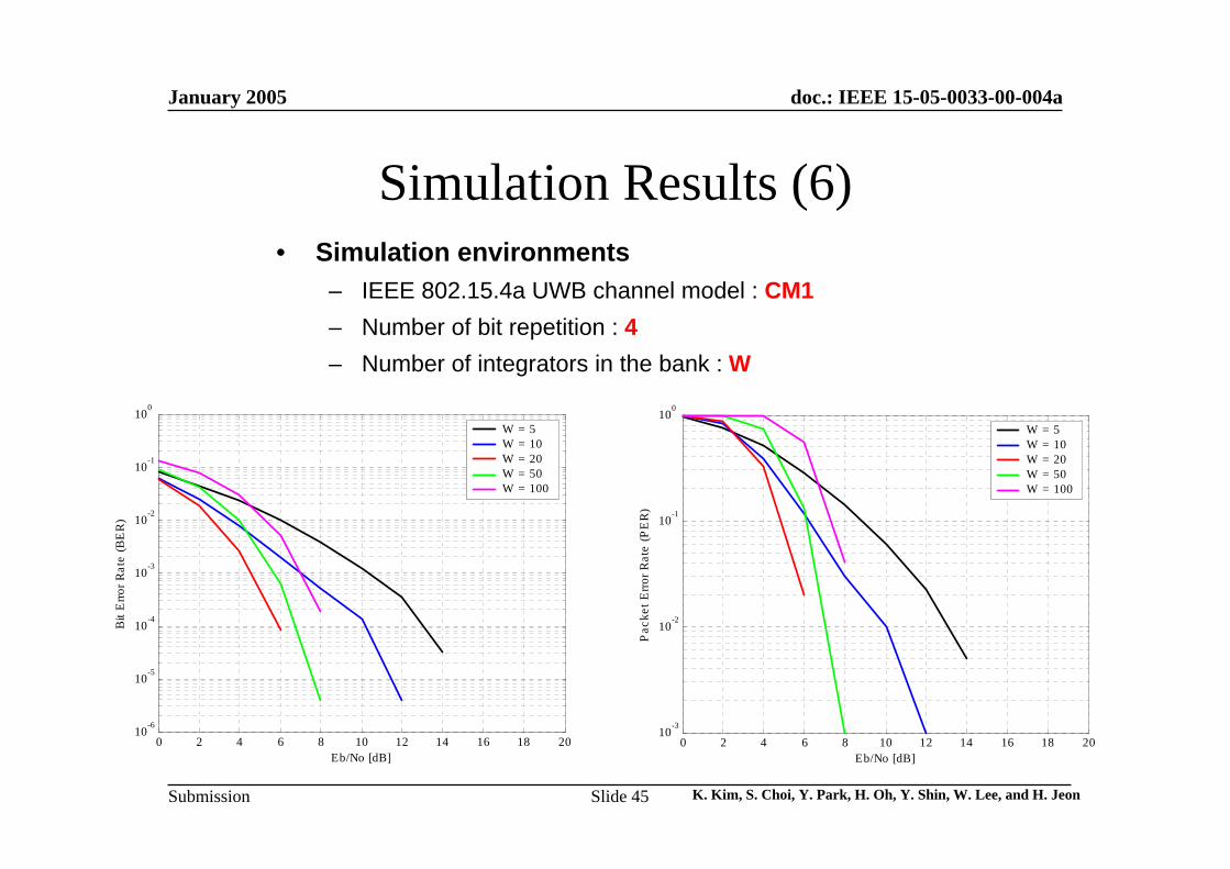
Simulation Results (6)
0 2 4 6 8 10 12 14 16 18 2010
-6
10-5
10-4
10-3
10-2
10-1
100
Bit
Erro
r Rat
e (B
ER
)
Eb/No [dB]
W = 5W = 10W = 20W = 50W = 100
0 2 4 6 8 10 12 14 16 18 2010
-3
10-2
10-1
100
Pac
ket E
rror R
ate
(PE
R)
Eb/No [dB]
W = 5W = 10W = 20W = 50W = 100
• Simulation environments– IEEE 802.15.4a UWB channel model : CM1– Number of bit repetition : 4– Number of integrators in the bank : W
January 2005
K. Kim, S. Choi, Y. Park, H. Oh, Y. Shin, W. Lee, and H. JeonSlide 46
doc.: IEEE 15-05-0033-00-004a
Submission
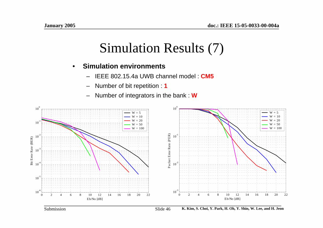
Simulation Results (7)
0 2 4 6 8 10 12 14 16 18 20 2210
-6
10-5
10-4
10-3
10-2
10-1
100
Bit
Erro
r Rat
e (B
ER
)
Eb/No [dB]
W = 5W = 10W = 20W = 50W = 100
0 2 4 6 8 10 12 14 16 18 20 2210
-3
10-2
10-1
100
Pac
ket E
rror R
ate
(PE
R)
Eb/No [dB]
W = 5W = 10W = 20W = 50W = 100
• Simulation environments– IEEE 802.15.4a UWB channel model : CM5– Number of bit repetition : 1– Number of integrators in the bank : W
January 2005
K. Kim, S. Choi, Y. Park, H. Oh, Y. Shin, W. Lee, and H. JeonSlide 47
doc.: IEEE 15-05-0033-00-004a
Submission
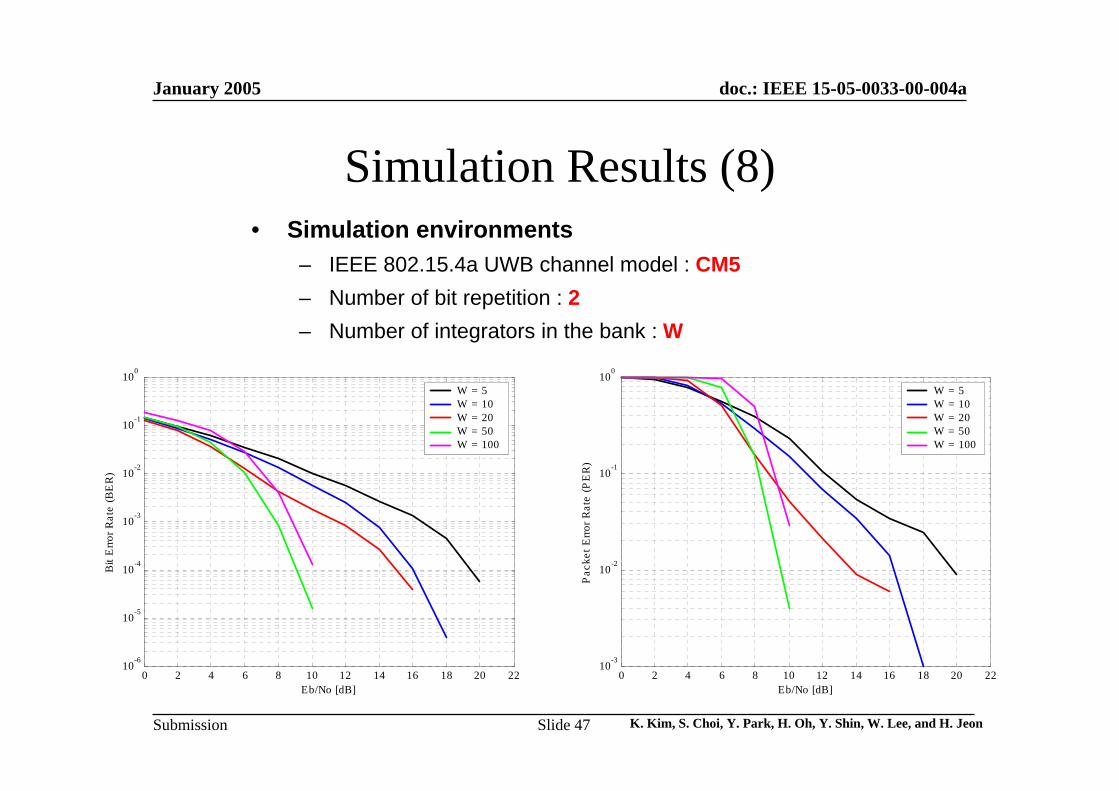
Simulation Results (8)
0 2 4 6 8 10 12 14 16 18 20 2210
-6
10-5
10-4
10-3
10-2
10-1
100
Bit
Erro
r Rat
e (B
ER
)
Eb/No [dB]
W = 5W = 10W = 20W = 50W = 100
0 2 4 6 8 10 12 14 16 18 20 2210
-3
10-2
10-1
100
Pac
ket E
rror R
ate
(PE
R)
Eb/No [dB]
W = 5W = 10W = 20W = 50W = 100
• Simulation environments– IEEE 802.15.4a UWB channel model : CM5– Number of bit repetition : 2– Number of integrators in the bank : W
January 2005
K. Kim, S. Choi, Y. Park, H. Oh, Y. Shin, W. Lee, and H. JeonSlide 48
doc.: IEEE 15-05-0033-00-004a
Submission
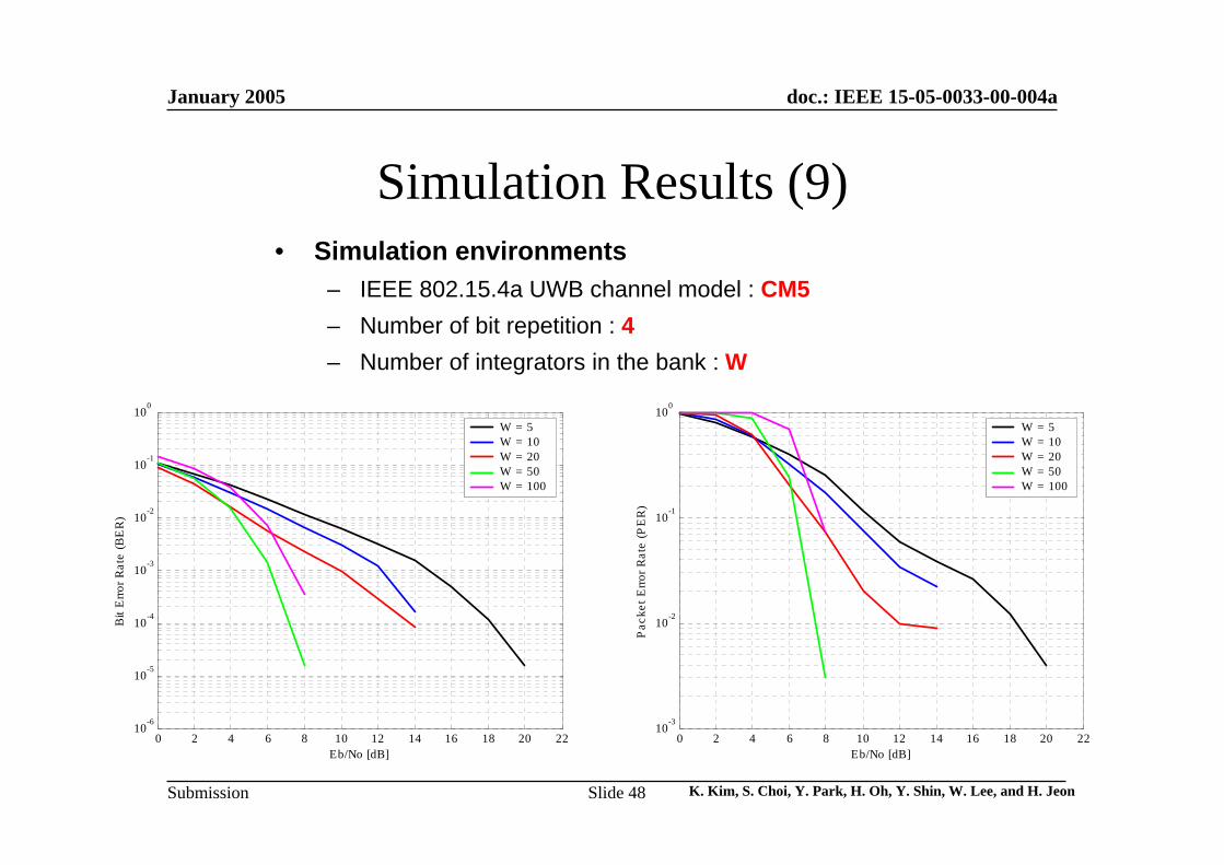
Simulation Results (9)
0 2 4 6 8 10 12 14 16 18 20 2210
-6
10-5
10-4
10-3
10-2
10-1
100
Bit
Erro
r Rat
e (B
ER
)
Eb/No [dB]
W = 5W = 10W = 20W = 50W = 100
0 2 4 6 8 10 12 14 16 18 20 2210
-3
10-2
10-1
100
Pac
ket E
rror R
ate
(PE
R)
Eb/No [dB]
W = 5W = 10W = 20W = 50W = 100
• Simulation environments– IEEE 802.15.4a UWB channel model : CM5– Number of bit repetition : 4– Number of integrators in the bank : W

January 2005
K. Kim, S. Choi, Y. Park, H. Oh, Y. Shin, W. Lee, and H. JeonSlide 49
doc.: IEEE 15-05-0033-00-004a
Submission
Link Budget &
Complexity and Power Consumption
January 2005
K. Kim, S. Choi, Y. Park, H. Oh, Y. Shin, W. Lee, and H. JeonSlide 50
doc.: IEEE 15-05-0033-00-004a
Submission
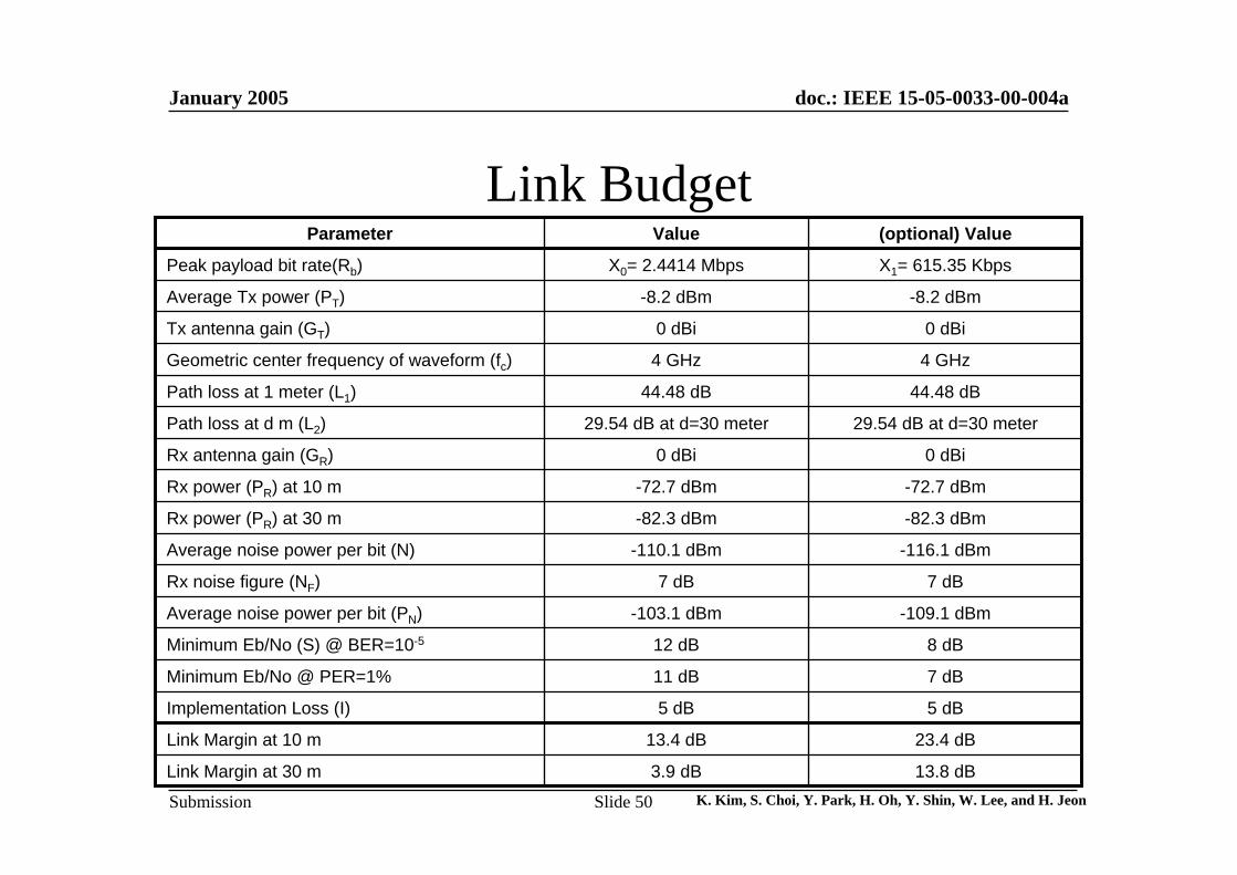
Link Budget
7 dB11 dBMinimum Eb/No @ PER=1%
23.4 dB13.4 dBLink Margin at 10 m
-72.7 dBm-72.7 dBmRx power (PR) at 10 m
0 dBi0 dBiTx antenna gain (GT)
13.8 dB3.9 dBLink Margin at 30 m
5 dB5 dBImplementation Loss (I)
8 dB12 dBMinimum Eb/No (S) @ BER=10-5
-109.1 dBm-103.1 dBmAverage noise power per bit (PN)
7 dB7 dBRx noise figure (NF)
-116.1 dBm-110.1 dBmAverage noise power per bit (N)
-82.3 dBm-82.3 dBmRx power (PR) at 30 m
0 dBi0 dBiRx antenna gain (GR)
29.54 dB at d=30 meter29.54 dB at d=30 meterPath loss at d m (L2)
44.48 dB44.48 dBPath loss at 1 meter (L1)
4 GHz4 GHzGeometric center frequency of waveform (fc)
-8.2 dBm-8.2 dBmAverage Tx power (PT)
X1= 615.35 KbpsX0= 2.4414 MbpsPeak payload bit rate(Rb)
(optional) ValueValueParameter
January 2005
K. Kim, S. Choi, Y. Park, H. Oh, Y. Shin, W. Lee, and H. JeonSlide 51
doc.: IEEE 15-05-0033-00-004a
Submission
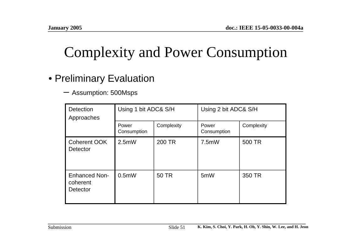
Complexity and Power Consumption
Coherent OOK Detector
350 TR5mW50 TR0.5mWEnhanced Non-coherent Detector
500 TR7.5mW200 TR2.5mW
ComplexityPower Consumption
ComplexityPower Consumption
Using 2 bit ADC& S/HUsing 1 bit ADC& S/HDetectionApproaches
• Preliminary Evaluation– Assumption: 500Msps
January 2005
K. Kim, S. Choi, Y. Park, H. Oh, Y. Shin, W. Lee, and H. JeonSlide 52
doc.: IEEE 15-05-0033-00-004a
Submission
Conclusions• Enhanced Noncoherent OOK UWB transceiver with energy detection
can meet the low power, low cost, and simple architecture– Edge-triggered OOK signals and data repetition for better detection– Three modes (timing/calibration/operation) in the receiver for
system performance improvement – Roughly synchronized TDM, randomly or sequentially allocated for
SOP• TDOA/TWR positioning & ranging techniques
– Asynchronous ranging by round trip time– Positioning based on sequential relay transmission– Positioning scenarios according to network topologies– Modifying MAC command frame for SOP and positioning– Energy window bank with low clock speed for energy detection and
ranging accuracy improvement