january 6th, 2016 presenter: dr. massimo mitolo, esi … · the analysis and grounding of power...
TRANSCRIPT

Event to start shortly Scheduled time: 11:00 USA Eastern Standard Time
1
January 6th, 2016Presenter: Dr. Massimo Mitolo, ESI Inc.Title: Understanding NEC and IEC in the matter ofbonding and grounding of low-voltage power systems
IAS Webinar series - 1/6/2015IAS Webinar Series
2
Webinar Presenter: Dr. Massimo MitoloMassimo Mitolo, Ph.D., P.E., P. Eng.
Ph.D. in Electrical Engineering from the University of Napoli“Federico II,” Napoli, Italy
Prominent Lecturer of IAS Authored over 75 journal papers Two books:
1. Electrical Safety of Low-Voltage Systems (McGraw-Hill, 2009)
2. Laboratory Manual for Introduction to Electronics: ABasic Approach (Pearson Prentice-Hall, 2013)
Registered Professional Engineer in California and Italy Currently working as a senior consultant with Engineering
Systems Inc. (ESI) in Foothill Ranch, CA, USA Area of expertise includes electrical safety engineering, and
the analysis and grounding of power systems Active within the Industrial and Commercial Power Systems
Department of IAS, as Department Secretary, Chair of thePower Systems Analysis Subcommittee, and Chair of theGrounding Subcommittee
IAS Webinar Series
Outline Identify key concepts in the NEC for bonding and
grounding Clarify the terminology used by IEC standards, with
regards to the protection against indirect contact in ac(50/60 Hz) systems by automatic disconnection ofsupply.
Examine types of grounding systems Examine “Bonding” Compare the EGCs/PE Conductor sizing procedures in
IEC and NEC Discuss key technical concepts present in the IEC
world regarding “bonding”
333
IAS Webinar Series
NEC Art. 90.1 (1)
4
Purpose.(A)Practical Safeguarding. The purpose of this Code is thepractical safeguarding of persons and property fromhazards arising from the use of electricity.(B)Adequacy. This Code contains provisions that areconsidered necessary for safety. Compliance therewith andproper maintenance results in an installation that isessentially free from hazard but not necessarily efficient,convenient, or adequate for good service or futureexpansion of electrical use.
IAS Webinar Series
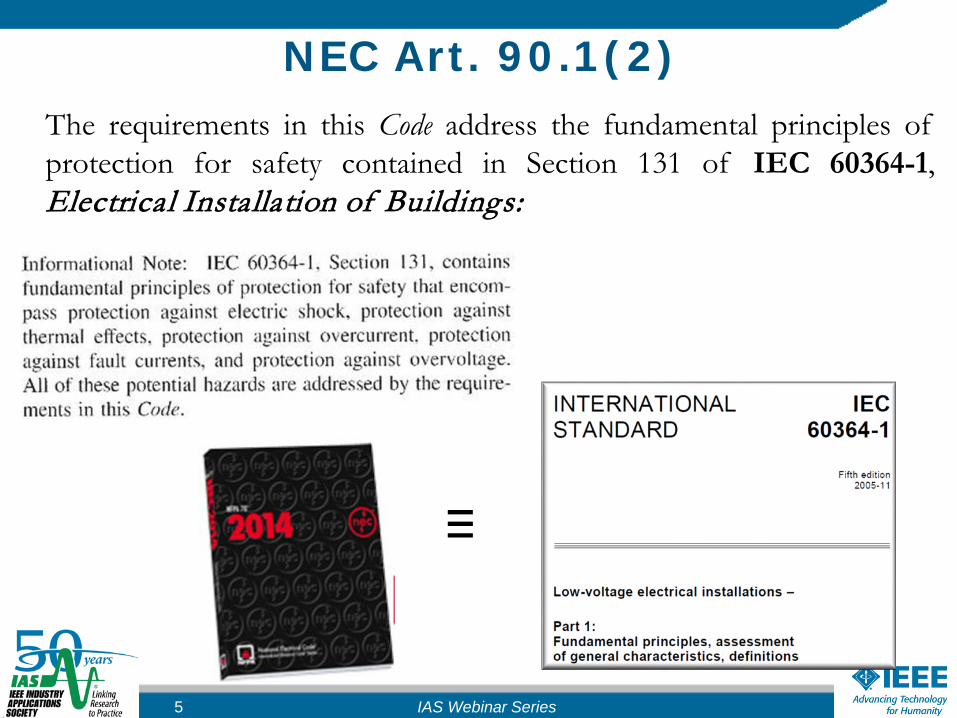
NEC Art. 90.1(2)The requirements in this Code address the fundamental principles ofprotection for safety contained in Section 131 of IEC 60364-1,Electrical Installation of Buildings:
≡
5 IAS Webinar Series
6
NEC Art. 250.4(3)Bonding of Electrical Equipment.
Normally noncurrent-carrying conductive materials enclosingelectrical conductors or equipment, or forming part of suchequipment, shall be connected together and to the electricalsupply source in a manner that establishes an effective groundfault current path.
IAS Webinar Series
7
NEC Art. 250.4(4)Bonding of Electrically Conductive Materials and
Other EquipmentNormally non-current-carrying electrically conductivematerials that are likely to become energized shall beconnected together and to the electrical supply source in amanner that establishes an effective ground fault current path.
IAS Webinar Series

IEC 60364-1 Definitions (1)Exposed-Conductive-Parts (ECP): conductive elements,forming part of the electrical system, which can be touched(even if out of reach) and is not live, but likely to becomelive when basic insulation fails.
8
IAS Webinar Series
9
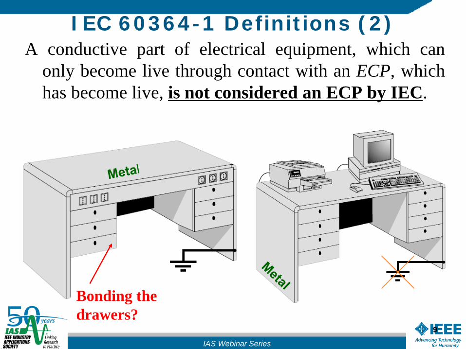
A conductive part of electrical equipment, which canonly become live through contact with an ECP, whichhas become live, is not considered an ECP by IEC.
Bonding the drawers?
IEC 60364-1 Definitions (2)
IAS Webinar Series

10
IEC 60364-1 Definitions (3)
direct contact: contacts with parts normally live (e.g.a damaged wire)
indirect contact: contacts with metal parts normallynot energized, but likely to become live upon faults(e.g. faulty equipment).
Protections against direct and indirect contact are alsorespectively referred to as basic and fault protections.
IAS Webinar Series

11
IEC 60364-1 Definitions (4)
Both IEC and NEC prescribe that ECPs shall:
be connected to the same earthing system individually, ingroups or collectively, via a protective conductor (PE).
be connected to earth, together and to the electricalsupply source via an equipment grounding conductor.
IAS Webinar Series
IEEE Standard P3003.2 "Recommended Practice for Equipment Grounding and Bonding inIndustrial and Commercial Power Systems”; August 2014.

12
IEC 60364-1 Definitions (5)Extraneous-Conductive-Parts (EXCP): conductiveelements, not forming part of the electrical system, liable tointroduce a “zero” potential or an arbitrary potential.
IAS Webinar Series

13
continued EXCP
??
IAS Webinar Series
Jamb non-intentionally grounded if incontact with re-bars.

14
continued EXCP
IAS Webinar Series
Totem: one that serves as an emblem or revered symbol
15
NEC Grounding Electrode (1)NEC defines the IEC EXCPs as non-intentional ground
electrodes within the facility, such as:
metal underground water pipe metal frame of the building (if effectively grounded) reinforcing bars in concrete foundations.
“[…] All the grounding electrodes present in a buildingmust be bonded together to form a grounding electrodesystem.”
IAS Webinar Series
Grounding Electrode (2)
NEC Article 250.68 (B): [...] Where necessary to ensure thegrounding path for a metal piping system used as agrounding electrode, bonding shall be provided around insulatedjoints and around any equipment likely to be disconnected for repairs orreplacement […].
16 IAS Webinar Series
17
Grounding Electrode (3)
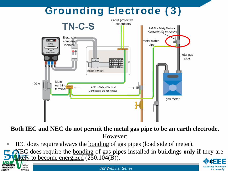
Both IEC and NEC do not permit the metal gas pipe to be an earth electrode.However:
IEC does require always the bonding of gas pipes (load side of meter). NEC does require the bonding of gas pipes installed in buildings only if they are
likely to become energized (250.104(B)).IAS Webinar Series

Ground electrode (3) IEC 60364-5-54 does not permit water pipes to be reliedupon as earth electrodes, even with the consent of the waterdistributor, being questionable their metallic continuity intime;
both NEC and IEC 60364-5-54 concur that metallic pipesemployed for flammable liquids or gases must not be used asan earth electrode.
However, as per IEC 60364-5-54 this requirement does notpreclude the protective bonding connection of such pipeson the load side of the meter.IEC 60364-5-54 “Electrical installations of buildings –Part 5-54: “Selection and erection of electricalequipment – Earthing arrangements, protective conductors and protective bonding conductors”:
18 IAS Webinar Series

World Grounding Map
19
Unknown
IAS Webinar Series

20
TT (Terre – Terre) Systems
Algeria, Belgium, Denmark, Egypt, France, Greece, Italy, Japan, Kenya, Luxemburg, Morocco, Tunisia, Spain,
Portugal, Turkey, United Arab Emirates, etc.IAS Webinar Series
TT System (1)
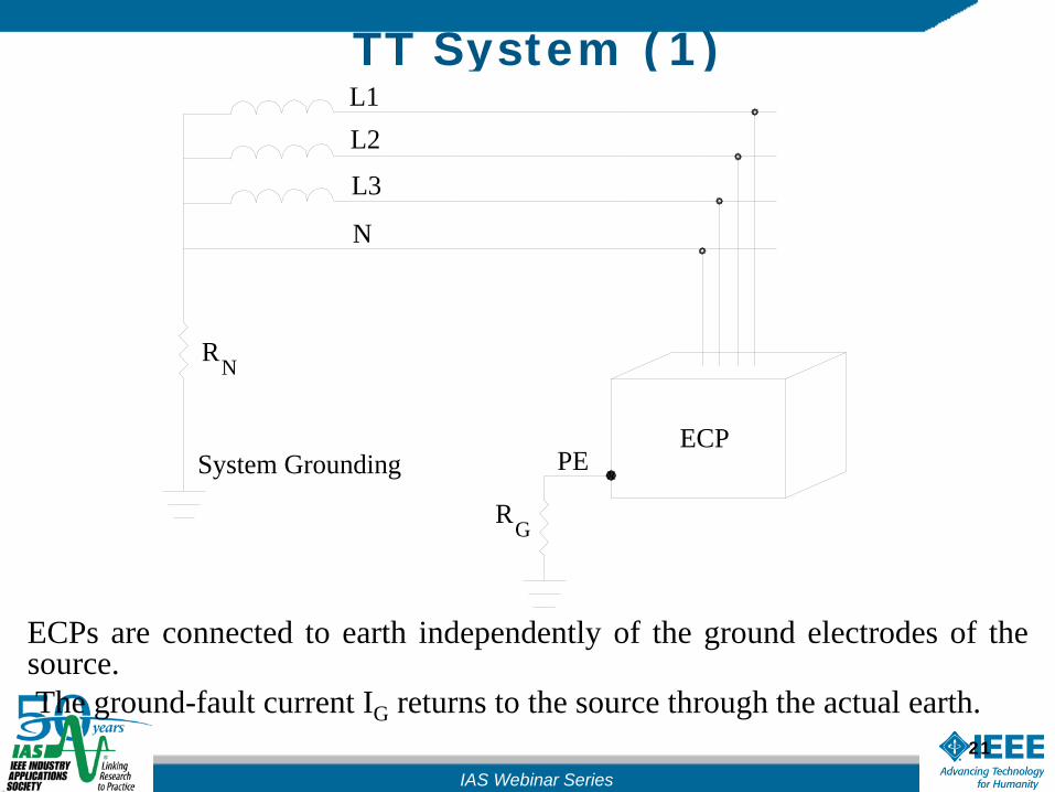
ECPs are connected to earth independently of the ground electrodes of thesource.The ground-fault current IG returns to the source through the actual earth.
IAS Webinar Series
21
RG
ECP
NR
PE
N
System Grounding
L3
L2L1
22
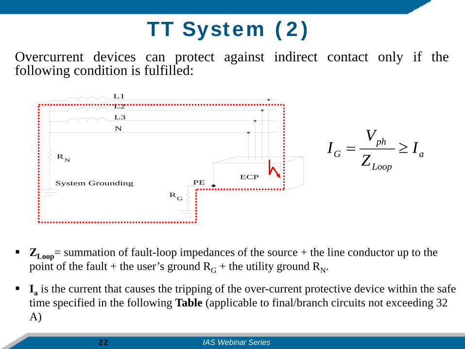
TT System (2)Overcurrent devices can protect against indirect contact only if thefollowing condition is fulfilled:
aLoop
phG I
ZV
I ≥=
ZLoop= summation of fault-loop impedances of the source + the line conductor up to the point of the fault + the user’s ground RG + the utility ground RN.
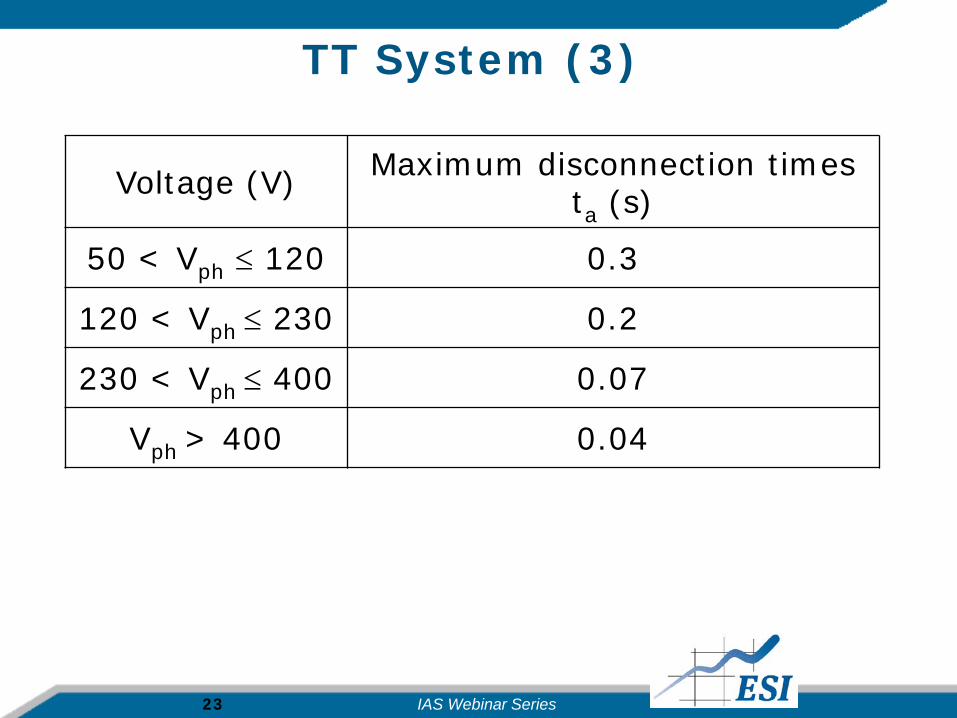
Ia is the current that causes the tripping of the over-current protective device within the safe time specified in the following Table (applicable to final/branch circuits not exceeding 32 A)
RG
ECP
NR
PE
N
System Grounding
L3
L2L1
IAS Webinar Series
23
TT System (3)
Voltage (V) Maximum disconnection times ta (s)
50 < Vph ≤ 120 0.3
120 < Vph ≤ 230 0.2
230 < Vph ≤ 400 0.07
Vph > 400 0.04
IAS Webinar Series
24
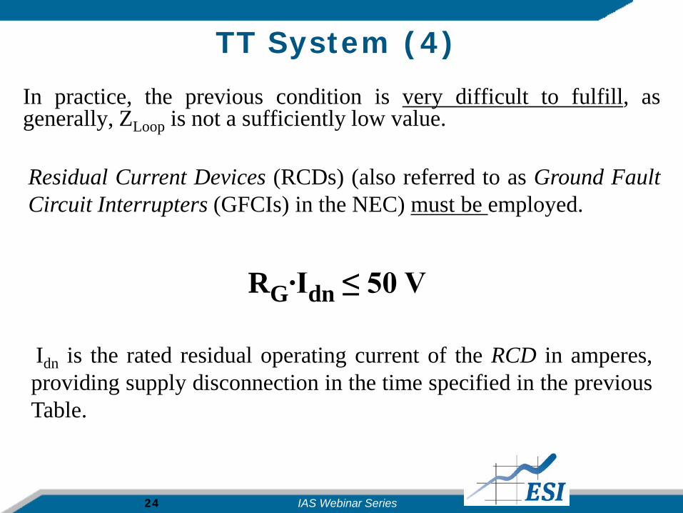
TT System (4)In practice, the previous condition is very difficult to fulfill, asgenerally, ZLoop is not a sufficiently low value.
RG∙Idn ≤ 50 V
Residual Current Devices (RCDs) (also referred to as Ground FaultCircuit Interrupters (GFCIs) in the NEC) must be employed.
Idn is the rated residual operating current of the RCD in amperes,providing supply disconnection in the time specified in the previousTable.
IAS Webinar Series
25
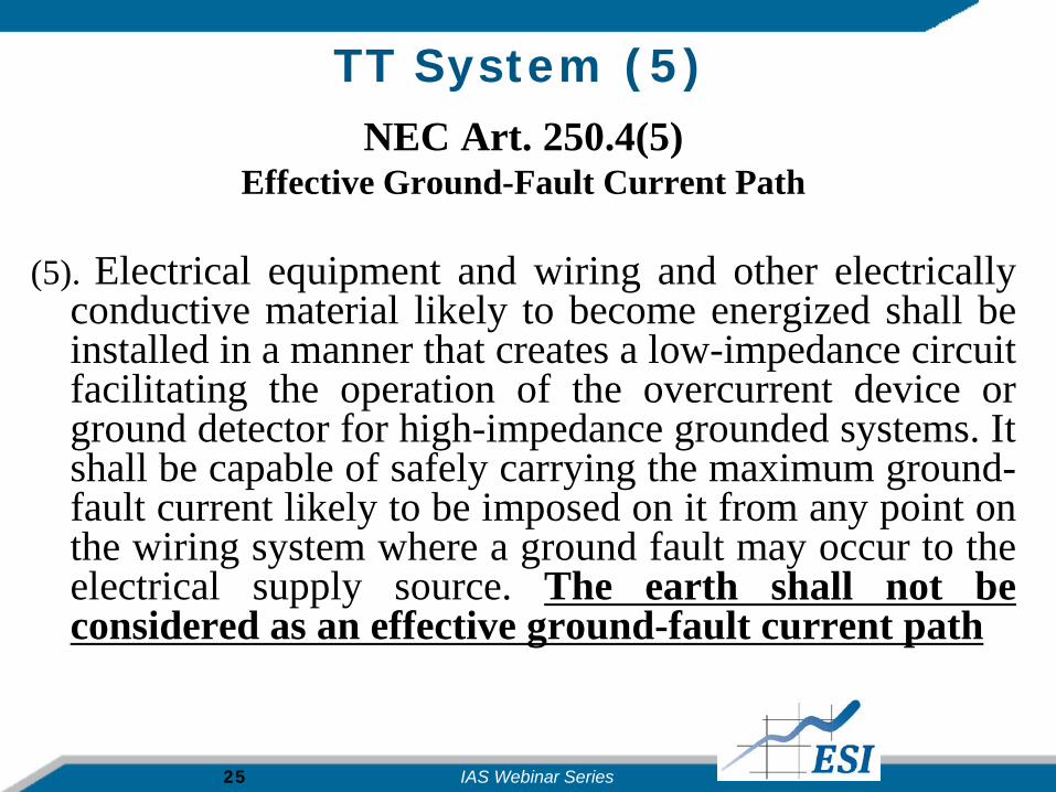
TT System (5) NEC Art. 250.4(5)
Effective Ground-Fault Current Path
(5). Electrical equipment and wiring and other electricallyconductive material likely to become energized shall beinstalled in a manner that creates a low-impedance circuitfacilitating the operation of the overcurrent device orground detector for high-impedance grounded systems. Itshall be capable of safely carrying the maximum ground-fault current likely to be imposed on it from any point onthe wiring system where a ground fault may occur to theelectrical supply source. The earth shall not beconsidered as an effective ground-fault current path
IAS Webinar Series

26
TN (Terre – Neutral) Systems
Australia, Canada, Germany, South Africa, Sweden, Switzerland, the UK, USA, etc.
IAS Webinar Series
27
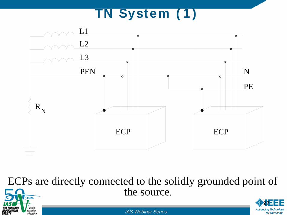
TN System (1)
ECPs are directly connected to the solidly grounded point of the source.
PE
N
ECP ECP
NR
PEN
L3
L2L1
IAS Webinar Series
28
ECP
NR
PEN
System Grounding
L3
L2L1
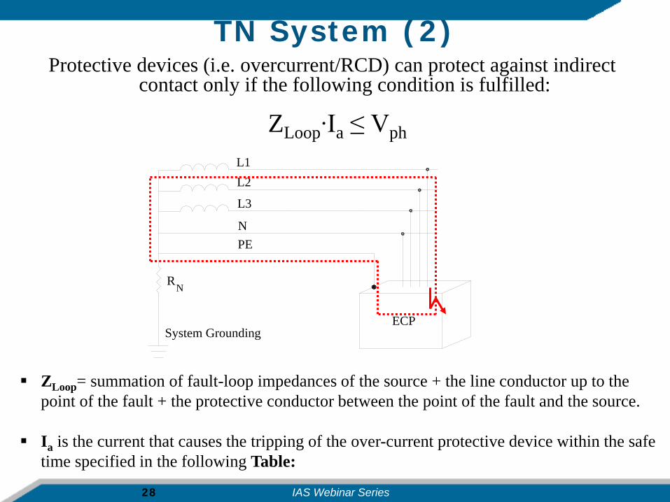
TN System (2)Protective devices (i.e. overcurrent/RCD) can protect against indirect
contact only if the following condition is fulfilled:
ZLoop= summation of fault-loop impedances of the source + the line conductor up to the point of the fault + the protective conductor between the point of the fault and the source.
Ia is the current that causes the tripping of the over-current protective device within the safe time specified in the following Table:
ZLoop∙Ia ≤ Vph
IAS Webinar Series
29
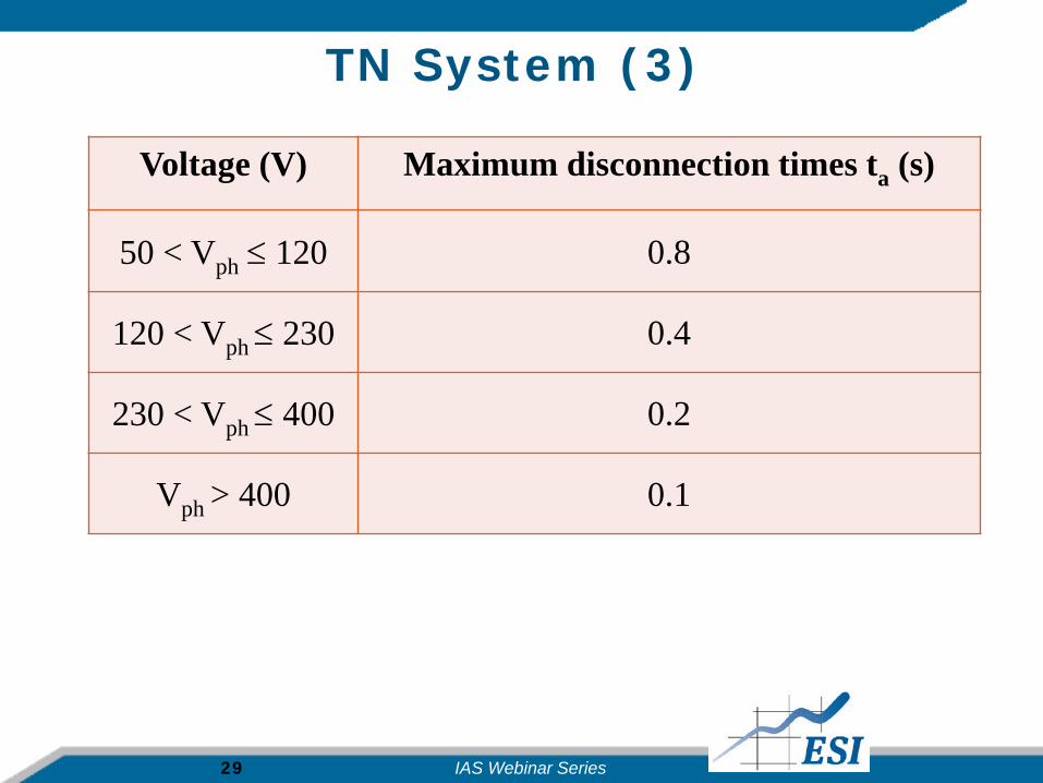
TN System (3)
Voltage (V) Maximum disconnection times ta (s)
50 < Vph ≤ 120 0.8
120 < Vph ≤ 230 0.4
230 < Vph ≤ 400 0.2
Vph > 400 0.1
IAS Webinar Series
30
IT (Isolation -Terre) Systems
Norway; Albania; Iran; Iraq; Peru; critical facilities
IAS Webinar Series
31
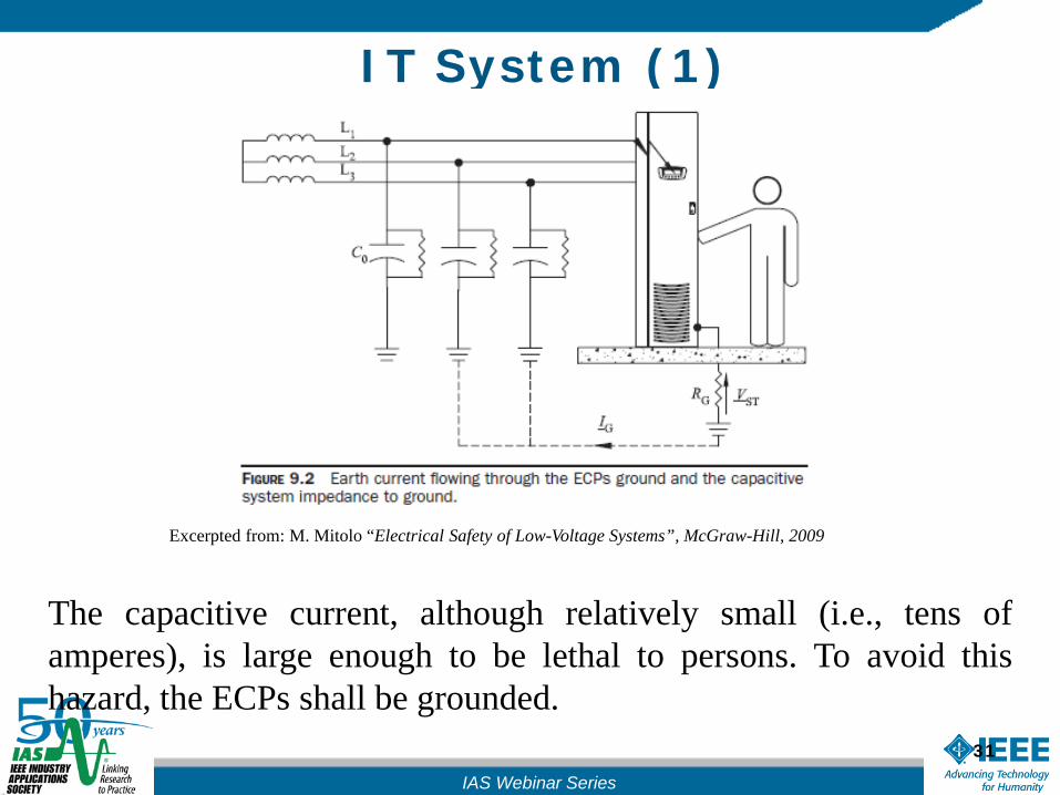
IT System (1)
The capacitive current, although relatively small (i.e., tens ofamperes), is large enough to be lethal to persons. To avoid thishazard, the ECPs shall be grounded.
Excerpted from: M. Mitolo “Electrical Safety of Low-Voltage Systems”, McGraw-Hill, 2009
IAS Webinar Series
32
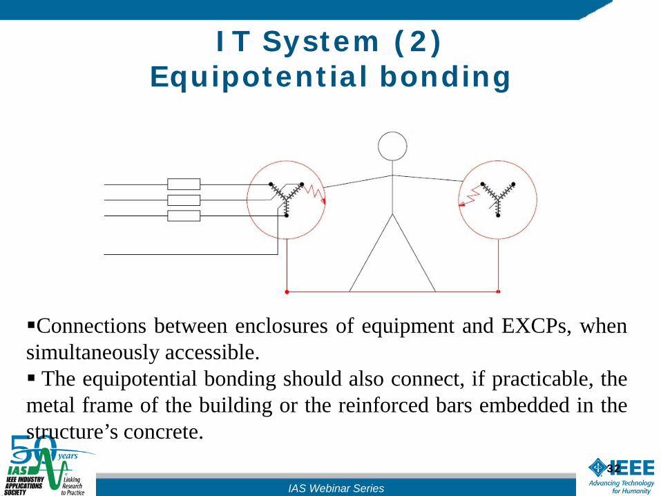
IT System (2)Equipotential bonding
Connections between enclosures of equipment and EXCPs, whensimultaneously accessible. The equipotential bonding should also connect, if practicable, themetal frame of the building or the reinforced bars embedded in thestructure’s concrete.
IAS Webinar Series

33
Public IT System (3)
The neutral point of the source of energy may be connected to earth through aspark gap, (also referred to as a disneuter) for protection against overvoltages
the utility generally delivers the PE to low-voltage dwelling units in urbanareas, where it is connected to a local earthing electrode;
Outside the city centers and in rural areas, the PE is generally not shipped, anduser’s equipment is solely grounded through their local earthing electrode
IAS Webinar Series
34
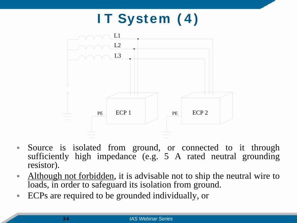
IT System (4)
Source is isolated from ground, or connected to it throughsufficiently high impedance (e.g. 5 A rated neutral groundingresistor).
Although not forbidden, it is advisable not to ship the neutral wire toloads, in order to safeguard its isolation from ground.
ECPs are required to be grounded individually, or
L1L2
L3
PEECP 1 ECP 2PE
IAS Webinar Series

35
IT System (5)
In groups, or collectively. if touch voltages are less than 50 V, the disconnection of
supply as a protection against indirect contact is neither required, nor necessary for safety
L1L2
L3
N
PEECP 1 ECP 2
PD 1 PD 2
IAS Webinar Series
36
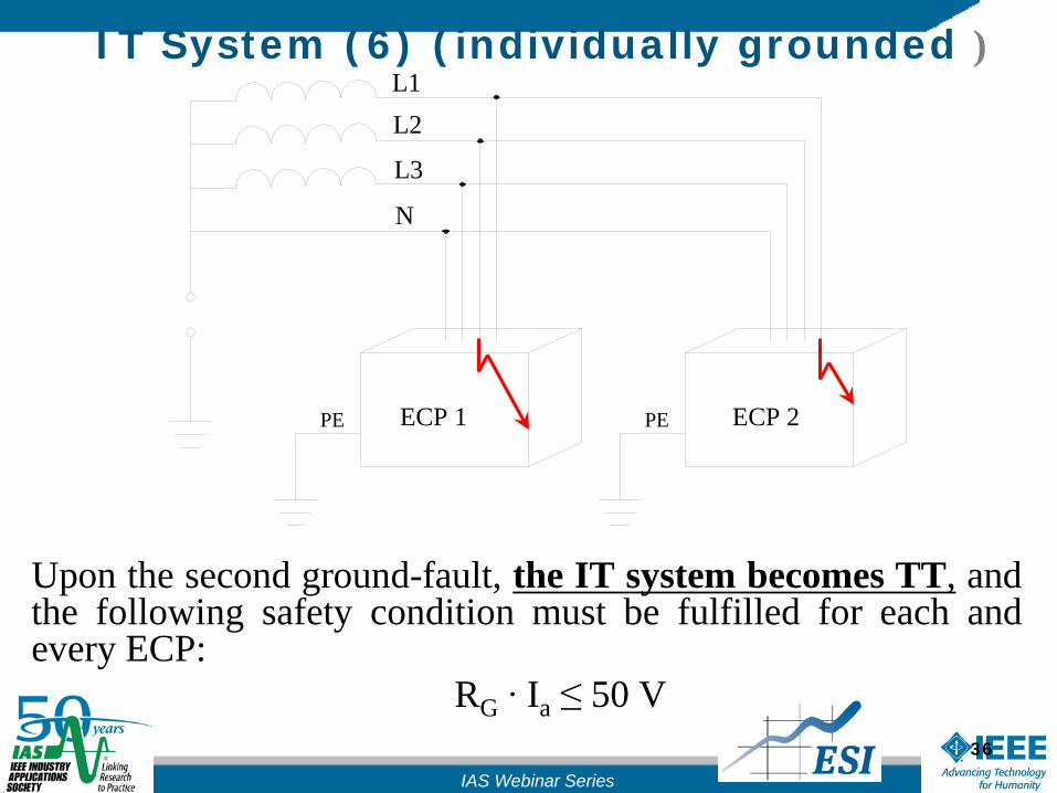
IT System (6) (individually grounded )
Upon the second ground-fault, the IT system becomes TT, andthe following safety condition must be fulfilled for each andevery ECP:
RG ∙ Ia ≤ 50 V
L1L2
L3
N
PEECP 1 ECP 2PE
IAS Webinar Series
37
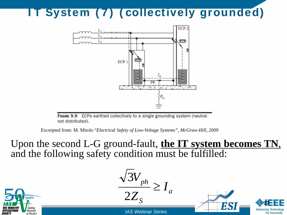
IT System (7) (collectively grounded)
Upon the second L-G ground-fault, the IT system becomes TN,and the following safety condition must be fulfilled:
aS
ph IZV
≥23
Excerpted from: M. Mitolo “Electrical Safety of Low-Voltage Systems”, McGraw-Hill, 2009
IAS Webinar Series
38
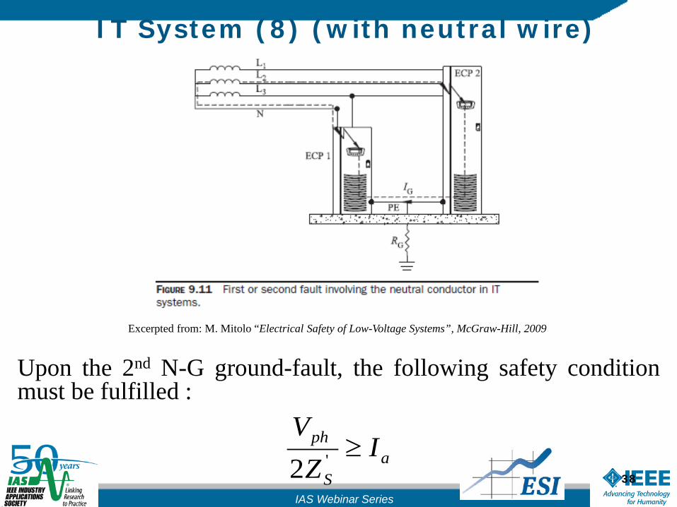
IT System (8) (with neutral wire)
Upon the 2nd N-G ground-fault, the following safety conditionmust be fulfilled :
aS
ph IZ
V≥'2
Excerpted from: M. Mitolo “Electrical Safety of Low-Voltage Systems”, McGraw-Hill, 2009
IAS Webinar Series
39
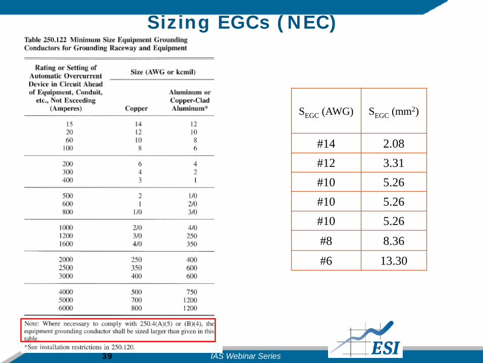
Sizing EGCs (NEC)
SEGC (AWG) SEGC (mm2)
#14 2.08#12 3.31#10 5.26#10 5.26#10 5.26#8 8.36#6 13.30
IAS Webinar Series

40
Sizing Protective Conductors(IEC 60364-5-54)
Minimum sizes as a function of the cross-sectional area S of the phaseconductor
Phase conductor S (mm2) PE (mm2)
S ≤ 16 S
16 < S ≤ 35 16S > 35 S/2
IAS Webinar Series

41
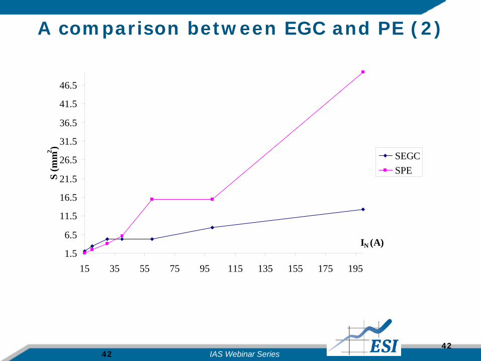
A comparison between EGC and PE (1)
NEC IECIN
(A)SEGC
(AWG)SEGC
(mm2) IZ (A) S (mm2)(trade size)
SPE (mm2)(trade sizes)
15 #14 2.08 17.5 1.5 1.520 #12 3.31 24 2.5 2.530 #10 5.26 32 4 440 #10 5.26 41 6 660 #10 5.26 76 16 16100 #8 8.36 101 25 16200 #6 13.30 232 95 50
IAS Webinar Series
42
A comparison between EGC and PE (2)
42
1.5
6.5
11.5
16.5
21.5
26.5
31.5
36.5
41.5
46.5
15 35 55 75 95 115 135 155 175 195
IN (A)
S (m
m2 )
SEGCSPE
IAS Webinar Series
43
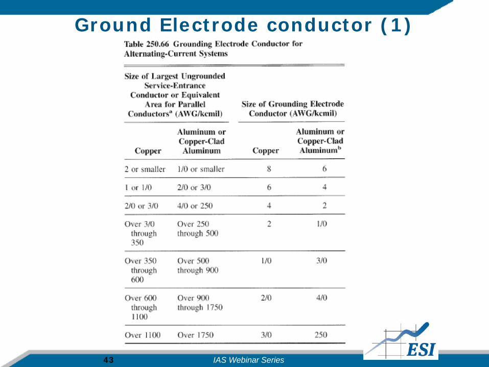
Ground Electrode conductor (1)
IAS Webinar Series

44
Ground Electrode
conductors (2)
Sline conductorSline conductor
(mm2) SGEC SGEC (mm2) SEC (mm2) SEC (mm2)IEC trade sizes
1 2 3 4 2 2.5
#6 or smaller 13.3 #8 8.36 13.3 16
#4 21.15 #8 8.36 16 16
#3 26.67 #8 8.36 16 16
#2 33.62 #8 8.36 16 16
#1 42.41 #6 13.3 21.2 25
#1/0 53.49 #6 13.3 26.74 35
#2/0 67.43 #4 21.15 33.71 35
#3/0 85.01 #4 21.15 42.5 50
#4/0 107.2 #2 33.62 53.6 70
250 127 #2 33.62 63.5 70
350 177 #2 33.62 88.5 95
400 203 #1/0 53.49 101.5 120
500 253 #1/0 53.49 126.5 150
600 304 #1/0 53.49 152 185
700 355 #2/0 67.43 177.5 185
800 405 #2/0 67.43 202.5 240
900 456 #2/0 67.43 228 240
1000 507 #2/0 67.43 253.5 300
1250 633 #3/0 85.01 316.5 -IAS Webinar Series

45
Ground Electrode conductors (3)
8
58
108
158
208
258
13 63 113 163 213 263 313 363 413 463
Sline (mm2)
S GE
C/S
EC
(mm
2 )
SGEC (mm2)
SEC (mm2)(IEC trade sizes)
IAS Webinar Series
46
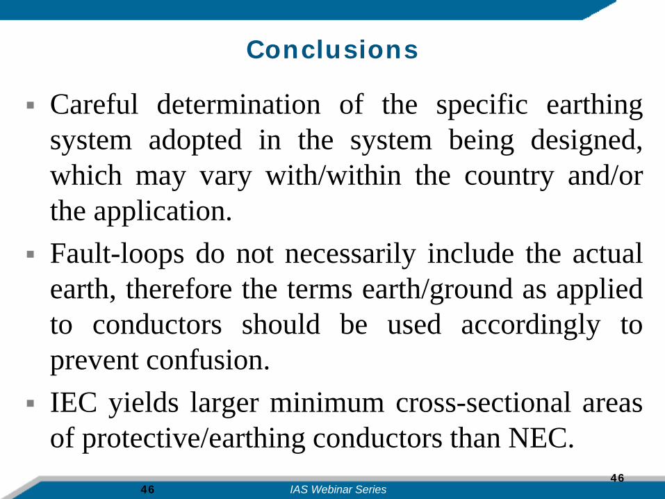
Conclusions
Careful determination of the specific earthingsystem adopted in the system being designed,which may vary with/within the country and/orthe application.
Fault-loops do not necessarily include the actualearth, therefore the terms earth/ground as appliedto conductors should be used accordingly toprevent confusion.
IEC yields larger minimum cross-sectional areasof protective/earthing conductors than NEC.
46IAS Webinar Series

47
IAS WEBINAR SERIESQuestions and Answers
If you have any question for the presenter:Use the Webex Q&A tab to send your question to the moderator
January 6th, 2016Presenter: Dr. Massimo Mitolo, ESI Inc.Title: Understanding NEC and IEC in the matter of bonding and grounding of low-voltage power systems
IAS Webinar Series
48
IAS WEBINAR SERIESCONCLUSION
We thank the presenter, Massimo Mitolo,and we thank you for your attention
This session was recorded and will be posted on line at:www.ias.ieee.org
Next webinar: February 3rd, 2016Presenter: Prof. Georges Zissis, Université de Toulouse, France
Title: Advances in Lighting Systems Technologies: Revolutions, Drawbacks and Strategies
IAS Webinar Series