jbete2 14 · hence making the tessellation origami a powerful form finding tool ... method used in...
TRANSCRIPT

Journal of Built Environment, Technology and Engineering, Vol. 2 (March) ISSN 0128-1003 2017
18
MODELING OF RIGID ORIGAMI TESSELLATION USING GENERATIVE ALGORITHM TOOL, GRASSHOPPER Chai Chen Chu Graduate Student, School of Civil Engineering Universiti Sains Malaysia, Nibong Tebal, 14300 Penang, Malaysia Email: [email protected] Choong Kok Keong Associate Professor, School of Civil Engineering Universiti Sains Malaysia, Nibong Tebal, 14300 Penang, Malaysia Email: [email protected]
ABSTRACT
In the recent years, origami tessellation has been actively explored by origamists around the world. The repeated folding pattern in the tessellation provides a folded state that is developable within a 3-dimensional surface. It gives a variety of folded surface that is suitable to adapt in building structure. Due to its complex folded surface, it is difficult to model it directly using drawing tool. At the moment, the modeling and simulation tool for rigid origami tessellation has limitation. This is because the folding motion is constrained by the high degree-of-freedom in the folding pattern. However, if the location of the actuator that can control the flexibility of the origami is found and properly restrained, a rigid structure can be achieved. The constraint can be identified by studying the loops connecting the facets bounds by a vertex or a set of vertices. Based on this, a method to model and simulate the folding of origami tessellation was proposed. This method only requires a simple programming tool such as the Grasshopper and do not require any extensive calculation. The resulted folded state is found using an algorithm presented in this paper. However, user is required to provide the mountain-valley pattern for the origami tessellation and provides the rotation angle for all the actuator to simulate the folding. The resulted tool has been used to simulate a variety of different variation of origami tessellation published on the internet. Keywords: origami tessellation, rigid origami, grasshopper3d, modeling.
Introduction In the past decades, the study of paper-folding art or origami has become the source of inspiration for many folded structure application in architectural and civil engineering such as the deployable structure, retractable structure and folded roof structure. Among the various type of origami, tessellation origami is the most studied origami in folded structure for architectural and building. The extensive review on the current study of tessellation origami in folded structure are found in the review paper by Sorguc et al. (2009) and Lebee (2015). Tessellation origami creates a 3-dimensional folded configuration with repeated local pattern covering a surface. Each facet is held side-by-side without any gap or overlapping of the facets. The folding of the tessellation origami into a folded configuration from a flat piece of paper provides variety of intermediate configurations. This is due to the high degree-of-freedom (DOF) of the folding pattern. One example of tessellation origami with flexible mechanism is the Ron Resch’s Waterbomb Pattern shown in Figure 1. Hence making the tessellation origami a powerful form finding tool for folded structure in architectural and building design (Moussavi, 2009; Sekularac et al., 2012)
Figure 1: Flexible configuration of the Ron Resch’s Waterbomb Pattern (Resch and Christiansen, 1970)

Journal of Built Environment, Technology and Engineering, Vol. 2 (March) ISSN 0128-1003 2017
19
The foldability issue related to global folding of high DOF folding pattern is still an open question. Many modeling and simulation tools are conducted based on tessellation pattern with one DOF mechanism. One example is the existing computer based simulation tool for tessellation pattern, Rigid Origami Simulator presented by Tachi (2006). Tachi (2006) utilised the conditions by Belcastro and Hull (2002) to solve the problem of folding pattern with multi-vertex intersection by using the global constraint of the rotational matrices representing the pattern. However, it can only be used to find solution for tessellation patterns with one DOF which include the Miura-Ori Pattern, Waterbomb (Triangle) Pattern and pleated hypars. Besides that, many other folding simulation tools make use of the generalization of single-vertex by Tachi (2009) to perform a synchronized folding mechanism. Synchronised folding is a folding that is controlled by local pattern. Change in local folding is simultaneously reflected in the other repeated local pattern. This is the main approach used in the design of simulation and modeling computational tools by Balkcom and Mason (2008), Hawkes et al. (2010), Schenk and Guest (2011), Landen (2013), Wei et al. (2013) and Xi and Lien (2015). Synchonised folding is also a popular method used in the form-finding using tessellation origami for architectural design. Geometric modeling for folding pattern is performed using parametric modeling or generative modeling approach by combining the computational geometry with programming algorithm. This type of geometric modeling techniques can be generated using graphical programming editor tool such as Grasshopper®, Python and Mathlab. The folding of tessellation origami is controlled by the independent variables and has provided an alternative to computational modeling in the field of architectural and civil engineering. Some of the geometric modellings are presented by Buri (2006), Dureisseix et al. (2011), Woerd (2012) and Chudoba et al. (2014). However, these approaches do not address the issue of foldability for high DOF folding pattern. The presented method is limited to simple folding pattern which has one DOF folding mechanism globally or locally. This is due to the folding mechanism with high DOF is too flexible and difficult to control. However, origami tessellation with high flexibility has more variety of folded configurations. Thus, the simulation tool for high DOF folding mechanism can serve as form finding tool for folded structure. Formulation of the algorithm for origami simulation using generative modeling can provide a great opportunity for others to study more tessellation origami design. Hence, this study aims to provide a modeling solution for tessellation pattern with high DOF using a graphical programming tool. This paper presents the method to simulate the folding pattern using a graphical programming tool, Grasshopper3D®. Grasshopper3D® is a generative algorithm tool that served as a plug-in for CAD software, Rhinoceros3D®. This tool is selected because the programming tool produces the corresponding 3D CAD result concurrently and this feature is suitable for simulating the origami tessellation folding procedure. The following sections describe the steps in geometric modeling for origami folding using generative algorithm tool, Grasshopper®. The first section presents the steps to generate the kinematic of the folding mechanism using the fold angle imposed on crease line. The second section presents the considerations for closed vertex. A closed vertex is a vertex with no split or gap between two connected facets in the folded configuration. The third section presents the simulation of the transformation for three tessellation pattern that are commonly studied using the presented geometric modeling tool. The three tessellation patterns are the Miura-ori Pattern, Yoshimura Pattern and Waterbomb (square) Pattern. The final section presents the conclusion of the study. KINEMATIC OF ORIGAMI

Journal of Built Environment, Technology and Engineering, Vol. 2 (March) ISSN 0128-1003 2017
20
The kinematic of the folding evolved around each vertex is represented by a localised single vertex with a unit radius flat disk as shown in Figure 2. The folding procedure of the disk is incorporated into drawing steps involving geometric shapes. Vertex folding involved only the internal vertex point, VM and is carried out from one vertex to another. Say, there were n fold lines l1,…, ln emanating from the vertex point. Each crease line is represented using fold angles α1,…, αn and vector u1,…, un, u = (ux, uy, uz) and ux
2 + uy2 + uz
2 = 1. The dihedral angle between two facets denotes the fold angle. Positive fold angle +α represents a
mountain fold and negative fold angle -α represents a valley fold. Following the right-hand rule, the folding angle range for mountain line is 0 ≤ α ≤ π and valley line is -π ≤ α ≤ 0.
The process of folding around a vertex is illustrated using the disk shown in Figure 3. Firstly, an imaginary cut is applied to crease line l1. The cut detached facet S1 from facet Sn and hence created a disk with a split at l1. Folding process of the split disk is started by taking surface S1 as stationary. The vertex folding is started by u3,…, un, un+1 rotated around u2. Using the new position of u, the folding is continued with u4,…, un, un+1 rotated around u3. The folding ended with un+1 rotated around un. The single-vertex folding is completed if the resulted folding ended with the return of vector (un+1)j to the initial vertex (u1)i. Vector (un+1)j must be coincided with initial vertex (u1)i. Hence, un+1 and u1 have a dot product that is equal to 1.
Figure 2: Single-vertex representation (a) Crease line pattern (b) One unit radius disk
(a)
(b)
Figure 3: Illustration for Vertex Folding using a disk (a) Initial State (b) Fold Angle αj (c) Closing the split, Fold Angle αn
(a)
(b)
(c)
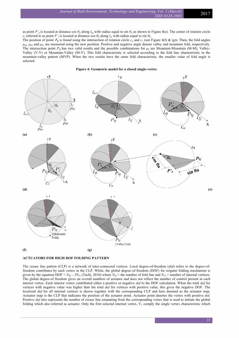
CHARACTERISTIC OF A CLOSED VERTEX For a localised single vertex, the degree-of-freedom(dof) equals to (n-3). The dof also represents the number of actuator required to fold the vertex. Hence, the vertex requires (n-3) of fold angle, ρc to control a fold. This 3 unknown fold angles, ρk are independent variables that cannot be changed. Three valid ρk is required to have a closed localised single vertex. The following geometric steps shown in Figure 4 represented the method to find the ρk by assuming all (n-3) fold angle is given. Fold angle ρk is restricted by the result of the intersection between two circles. Say, a single vertex has three unknown fold angles ρka, ρkb and ρk1 for crease line la, lb and l1 respectively, emanating from the vertex in anti-clockwise direction (see Figure 4(a)). The section angle between la, lb and l1 is θa and θb, respectively. The disk is folded up to la-1 (See Figure 4(b)) and at this stage, all new position for crease line is identified except for lb. Say endpoint for one unit length lb is point Pbj (see Figure 4(c) & (d)). Point Pbj rotates perpendicularly around laj and l1j along circle ca and c1, respectively. The center of rotation circle ca which is referred to
Journal of Built Environment, Technology and Engineering, Vol. 2 (March) ISSN 0128-1003 2017
21
as point P’a is located at distance cos θa along laj with radius equal to sin θa as shown in Figure 4(e). The center of rotation circle c1 referred to as point P’1 is located at distance cos θb along l1j with radius equal to sin θb. The position of point𝑃#is found using the intersection of rotation circle ca and c1 (see Figure 4(f) & (g)). Then, the fold angles ρka, ρkb and ρk1 are measured using the new position. Positive and negative angle denote valley and mountain fold, respectively. The intersection point Pbjhas two valid results and the possible combinations for ρk are Mountain-Mountain (M-M), Valley-Valley (V-V) or Mountain-Valley (M-V). This fold characteristic is selected according to the fold line characteristic in the mountain-valley pattern (MVP). When the two results have the same fold characteristic, the smaller value of fold angle is selected.
Figure 4: Geometric model for a closed single-vertex
(a)
(b)
(c)
(d) (e)
(f)
(g)
ACTUATORS FOR HIGH DOF FOLDING PATTERN The crease line pattern (CLP) is a network of inter-connected vertices. Local degree-of-freedom (dof) refers to the degree-of-freedom contributes by each vertex in the CLP. While, the global degree-of-freedom (DOF) for origami folding mechanism is given by the equation DOF = NEi - 3NVi (Tachi, 2010) where NEi = the number of fold line and NVi = number of internal vertices. The global degree-of freedom gives an overall numbers of actuator and does not reflect the number of control present in each interior vertex. Each interior vertex contributed either a positive or negative dof to the DOF calculation. When the total dof for vertices with negative value was higher than the total dof for vertices with positive value, this gives the negative DOF. The localized dof for all internal vertices is shown together with the corresponding CLP and here denoted as the actuator map. Actuator map is the CLP that indicates the position of the actuator point. Actuator point denotes the vertex with positive dof. Positive dof also represents the number of crease line emanating from the corresponding vertex that is used to initiate the global folding which also referred as actuator. Only the first selected internal vertex, V1 comply the single vertex characteristic which

Journal of Built Environment, Technology and Engineering, Vol. 2 (March) ISSN 0128-1003 2017
22
has dof = n-3. For the internal vertex from V1 onwards denoted as Vi, local degree-of-freedom dofi = ni – 3 - nci where nci number of crease line emanating from Vi that are connected to any V1,…, Vi-1. The dof computation is carried out from vertex to vertex until the dof for all internal vertices is calculated. IMPLEMENTATIONS Tessellation origami with high degree-of-freedom has large numbers of actuator. Hence the transformation involved a large numbers of fold angle. Therefore, a synchonised folding is proposed. However, synchonised folding only applied on the actuators. Examples of the simulated folding pattern are shown in Figure 8, 9 and 10 for Miura-ori Pattern, Yoshimura Pattern and Waterbomb (square) Pattern, correspondingly. Crease line represented the actuator is highlighted in the plan view using a thickened crease line. Fold angle applied on the actuator is shown in the top view of the following figures. Miura-ori Pattern in Figure 8(a) has global degree-of-freedom (DOF) = -79. However, in Figure 8(b), actuator map computation shows that Miura-ori has only one number of actuator which matched its one-dof folding mechanism claimed by Tachi(2010). Yoshimura Pattern and Waterbomb (Square) Pattern has high DOF, 25 and 37 respectively. Hence, actuators synchonisation is applied and the actuator is represented by using a single vertex representing the set of actuators. Figure 8 : Simulated Miura-ori Pattern with DOF = -79 (a) Plan View (b) Actuator Map (c) Side View (d) Top View (d) 3-
dimensional View
(a)
(b)
(c)
(d)
(e)

Journal of Built Environment, Technology and Engineering, Vol. 2 (March) ISSN 0128-1003 2017
23
Figure 9 : Simulated Yoshimura Pattern with DOF = 25 (a) Plan View (b) Actuator Map (c) Side View (d) Top View (e) 3-
Dimensional View
(a)
(b)
(c)
(d)
(e) Figure 10 : Simulated Waterbomb (Square) Pattern with DOF = 37 (a) Plan View (b) Actuator Map (c) Side View (d) Top
View (e) 3-Dimensional View

Journal of Built Environment, Technology and Engineering, Vol. 2 (March) ISSN 0128-1003 2017
24
(a)
(b)
(c)
(d)
(e) CONCLUSIONS This paper proposed an alternative simulation and modeling approach using generative algorithm tool Grasshopper®. The approach has enabled the folding simulation for high DOF tessellation pattern using an actuator map to orchestrate the folding path. The result provides the basic idea of modeling variety of origami tessellation using a simple programming tool. This paper also serves as an introduction to origami tessellation as a potential form-finding tool for folded structure. However, more study is required to realise the use of origami tessellation in the folded structure industry. The structural design of an origami tessellation as folded structure is only possible if there is a reliable modeling tool to represent the folded configuration. This paper presents the initial study on modeling of origami tessellation with high DOF. Folding pattern with high DOF has many choices of actuator map. At the moment, study on tessellation origami using the proposed simulation tool is limited by one number of actuator map. Further study on other variety of actuator map is required to explore more folded configuration. Due to high number of actuators, the presented tool is limited to synchronizing the folding of all actuator based on one local vertice

Journal of Built Environment, Technology and Engineering, Vol. 2 (March) ISSN 0128-1003 2017
25
representing the actuators. Further study is required to understand the mechanism of the origami tessellation by controlling the folding using individual actuator instead of synchronising the actuators. In the engineering issue, study on the structural analysis and constructability of the origami tessellation is also required in future study. REFERENCES Balkcom, D. J. & Mason, M. T. 2008. Robotic Origami Folding. The International Journal of Robotics Research, Vol. 27, p.p.
613-627. Belcastro, s.-m. & Hull, T. C. A Mathematical Model for Non-Flat Origami. In Origami3: Proceedings of the 3rd International
Meeting of Origami Mathematics, Science, and Education, 2002. p.p. 39-51. Buri, H. Die Technik des Origami im Holzbau - Faltwerke aus BSP-Elemente. Tagungs-Band 5 : Grazer Holzbautagung, 2006.
p.p. N1-N13. Chudoba, R., Woerd, J. V. D. & Hegger, J. 2014. Numerical modeling support for form-finding and manufacturing of folded
plate structures made of cementitious composites using origami principles. Computational Modelling of Concrete Structures. CRC Press.
Dureisseix, D., Gioia, F., Motro, R. E. & Maurin, B. Conception d'une Enveloppe Pliss'ee Pliable-D'epliable. 10e colloque national en calcul des structures, 2011 Giens, France. p.p. Cl´e USB, 2011. <hal-00592843>.
Hawkes, E., AN, B., Benbernou, N. M., Tanaka, H., Kim, S., Demaine, E. D., Rus, D. & Wood, R. J. Programmable Matter by Folding. Proceedings of the National Academy of Sciences of the United States of America, 2010. p.p. 12441-12445.
Landen, B. 2013. A Study of Action Origami as Systems of Spherical Mechanisms. Brigham Young University. Lebee, A. 2015. From Fold to Structure - A Review. International Journal of Space Structures, Vol. 30, p.p. 55-74. Moussavi, F. 2009. The Function of Form, ACTAR, Harvard Graduate School of Design. Resch, R. D. & Christiansen, H. The Design and Analysis of Kinematic Folded Plate Systems. Proceedings of IASS Symposium
on Folded Plates and Prismatic Structures, 1970 Vienna. Schenk, M. & Guest, S. D. Origami Folding - A Structural Engineering Approach. In: WANG-IVERSON, P., LANG, R. J. &
YIM, M., eds. Fifth International Meeting of Origami Science, Mathematics, and Education, 2011. CRC Press, p.p. 291-303.
Šekularac, N., Ivanović-Šekularac, J. & Čikić-Tovarović, J. 2012. Folded Structures in Modern Architecture. Facta Universitatis Vol. 10, p.p. 1-16.
Sorguc, A. G., Hagiwara, I. & Selcuk, S. A. 2009. Origamics in Architecture - A Medium of Inquiry for Design in Architectural. METU Journal of the Falculty of Architecture, Vol. 26, p.p. 235-247.
Tachi, T. Rigid Origami Simulator. In: LANG, R. J., ed. The Fourth International Meeting on Origami in Science, Mathematics, and Education (4OSME), 2006 Pasadena, California, USA. A K Peters/CRC Press, p.p. 175-187.
Tachi, T. Generalization of Rigid-Foldable Quadrilateral Mesh Origami. IASS Evolution and Trends in Design, Analysis and Construction of Shell and Spatial Structures, 2009.
Tachi, T. Geometric Considerations for the Design of Rigid Origami Structures. Proceedings of the International Association for Shell and Spatial Structures (IASS) Symposium : Spatial Structures – Permanent and Temporary, 2010 Shanghai, China. p.p. 771-782.
Wei, Z. Y., Guo, Z. V., Dudte, L., Liamg, H. Y. & Mahadevan, L. 2013. Geometric Mechanics of Periodic Pleated Origami. Physical Review Letters, Vol. 110, p.p. 215501.
Woerd, J. D. V. D. Finding New Forms for Bearing Structure by use of Origamics. In: MUELLER, H. S., ed. Proceedings of the 9th fib International PhD Symposium in Civil Engineering : Karlsruhe Institute of Technology (KIT), 22 - 25 July 2012 2012 Germany. KIT Scientific Publishing, p.p. 263-268.
Xi, Z. & Lien, J.-M. Folding and Unfolding Origami Tessellation by Reusing Folding Path. IEEE International Conference on Robotics and Automation (ICRA), 2015 Seattle, WA.