j.c.perezzan & s. hernandez - wit press...size and shape optimization of long portal bridges...
TRANSCRIPT

Size and shape optimization of long portal
bridges
J.C.Perezzan & S. HernandezE. T.S Ingenieros de Caminos, Canales y PuertosUniversity of La CorunaCampus de Elvina, La Coruna 15071, SpainEmail: [email protected];[email protected]
Abstract
Most applications in optimum design of frame structures have been devoted tosize optimization. In this paper a multispan bridge having a large number ofelements is presented as a case for design optimization. First, a size optimizationproblem is carried out having a number of design variables varying from 4 to118. Then size and shape optimization is formulated considering the span lengthas design variable for geometry optimization. Numerical results obtained showthe advantages of this combined approach.
1 Optimum design of flexural systems
Optimum design of flexural systems composed by bar elements is a very wellstablished topic on structural optimization. Plastic and elastic behaviour has beenconsidered for many authors using classical mathematical programming oremerging techniques as genetic algorithms or neural networks. References [1-11]represent an overview of results in different problems and typologies includingframes, grillages and beams.
While the number of applications is large, all of them are related with sizeoptimization. The design problem is posed usually in terms of the cross sectionareas of the bars which are considered design variables. Other mechanicalparameters, as inertia modulus /, or strength modulus W are linked to area A byusing the following expressions
7 = a,A*' W=a,,A^ (1)
Transactions on the Built Environment vol 37 © 1999 WIT Press, www.witpress.com, ISSN 1743-3509

288 Computer Aided Optimum Design of Structures
Sometimes, design optimization is made in several steps by carrying outmultilevel optimization techniques [12-13]. In that approach, the optimumvalues of the areas are first identified, then a second optimization problem issolved considering the internal dimensions of the cross section areas of the bar asdesign variables.
In this paper an application of size and shape optimization of portal bridgeswill be presented. The set of design variables will be composed by the values ofcross section areas A defined as a vector /4_, and the set of bars length L asindicated in Figure 1. Allowable stresses and vertical displacements will beadopted as constraints and the weight of material will be considered as objectivefunction. Hence, minimization problem may be written as
^
i, h
Figure 1. Size and shape of a portal bridge
K, = W, (X) (2.a)
being X the vector of design variables
X = %f&W (2.b)subjected to
a^<a(X)<(Tu (2.c)wW<%(/ (2.d)
whereWg weight of materialA. vector of cross section areasL vector of bars length<7 representative stress in a structural element0%, <j(/ lower and upper stress level of materialu representative vertical displacement of a structural elementUy upper bound of vertical displacement
2 Sensitivity analysis approaches
Efficient numerical optimization algorithms require first order information of theobjective function and the set of constraints of the design problem. Such kind ofinformation is known as sensitivities. First order sensitivity of a structuralresponse \// with respect to a design variable *, can be written as
dy _ dy/ ^¥_d^ (3)dx dx du dx
Transactions on the Built Environment vol 37 © 1999 WIT Press, www.witpress.com, ISSN 1743-3509

Computer Aided Optimum Design of Structures 289
It is well know that expression (3) may be solved by two approaches.In the direct differentiation method the following expression is finally
obtained
f- ——Aou
a)
b)
Alternatively, the adjoint approach leads to
doc(5)
Both techniques require to obtain the following:
Derivatives of vector of loading .~£.: The main class of loading depending
on the design variables is the self weight of the structure. This term isusually neglected in truss systems but it may be important in most flexuralsystems and it will be included in this paper.
Derivatives of stiffness matrix ^A: Derivatives of the stiffness matrix withdx,
respect to design variables as cross section area or other parameter related toit, as inertia modulus, is quite straight forward. But major difficulties appearif coordinates of nodes are included in the set of design variables. In thiscase the derivatives usually are not evaluated explicitly, and instead that arecarried out by finite differences procedures. In the piece of research presentedin this paper the derivatives of the stiffness matrix was done in closed form.Optimization was carried out using ADS [14] software using sensitivitiesprovided by the authors for both types of design variables: cross sectionareas and nodes coordinates.
3 Structural optimization of long portal bridges
The example included in this paper is a long bridge composed by twenty fourspans of 93.75 m of length and forty and three spans 250 m long each one.Because the symmetry only half of the bridge is shown in Figure 2.
L, 1 i ,
i i
, l4020
95.75 9J.75 250 725#72 #22
7725 ' 5J75
Figure 2. Geometry and loads considered
Transactions on the Built Environment vol 37 © 1999 WIT Press, www.witpress.com, ISSN 1743-3509
290 Computer Aided Optimum Design of Structures
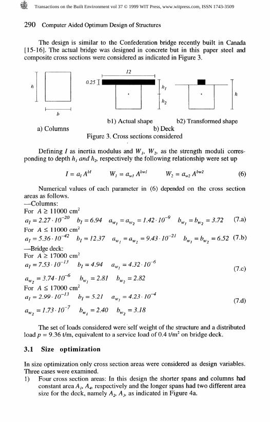
The design is similar to the Confederation bridge recently built in Canada[15-16]. The actual bridge was designed in concrete but in this paper steel andcomposite cross sections were considered as indicated in Figure 3.
&2J 11
a) Columnsbl) Actual shape b2) Transformed shape
b) DeckFigure 3. Cross sections considered
Defining / as inertia modulus and Wj, W/2, as the strength moduli corres-ponding to depth hj and /%, respectively the following relationship were set up
W, = a», Abwl W2 = \bw2 (6)
Numerical values of each parameter in (6) depended on the cross sectionareas as follows.—Columns:For A> 11000cm'
aj = 2.27 • 10~*° bj = 6.94 tf^ = a^ =1.42- 1C
For A < 11000cm*5-j S-- I y-»—42 1 J \ -J<~1 f\ A -J.36-10 bf = 12.37 a^ = a^ = 9.43-1
—Bridge deck:For A > 17000 cnf
6^=6^=3.72 (7.a)
(7.b)
a =3.74-70 6 =2.&7
For A < 17000 cnfa, = 2.99-JO-'* bj = 5.21
a, =7.73-70 6_ =2.40
= 4 J2 • 7
, = 2. 2
= 4.23 • 1
(7.c)
(7.d)
The set of loads considered were self weight of the structure and a distributedload p = 9.36 t/m, equivalent to a service load of 0.4 t/nf on bridge deck.
3.1 Size optimization
In size optimization only cross section areas were considered as design variables.Three cases were examined.1) Four cross section areas: In this design the shorter spans and columns had
constant area A/, A* respectively and the longer spans had two different areasize for the deck, namely A^ A,, as indicated in Figure 4a.
Transactions on the Built Environment vol 37 © 1999 WIT Press, www.witpress.com, ISSN 1743-3509

Computer Aided Optimum Design of Structures 291
^
n<
^"-1<
**-l<
"~-y<
1
^ K 3K
" ^
Q ^D _^?u "
1 i§ t
-# Jh
< 1% 3 <
k fN
> JT< ^ ^k
1?K
P:k
<" p.1% ^
^ ^
N %^< <^
k
PK
$k
t\ QO< < p
Ys
VV
ftfc
pk
t\ OQ< <K
k
6) <$ design variable case
T"
-C5
i
sri
V-i-qT
iQ\ofN<txr00«N<<IX«N5<•O<N<<"<rr,T
0
J
J
K oo*?*?&
k
tx oo^<TK
fc
N OD
&
10 OT T F
K
rn Xh<r <r K
^r^pK
^^rpk
^ PK
^s
3•2
00•*~
Figure 4. Design variables in size optimization
Transactions on the Built Environment vol 37 © 1999 WIT Press, www.witpress.com, ISSN 1743-3509

292 Computer Aided Optimum Design of Structures
2) Eight cross section areas: In this case the longer spans had four crosssection sizes, A?, A# A$, A& the shorter spans had two different areas Ay,A2, and also columns had two areas A 7, A&
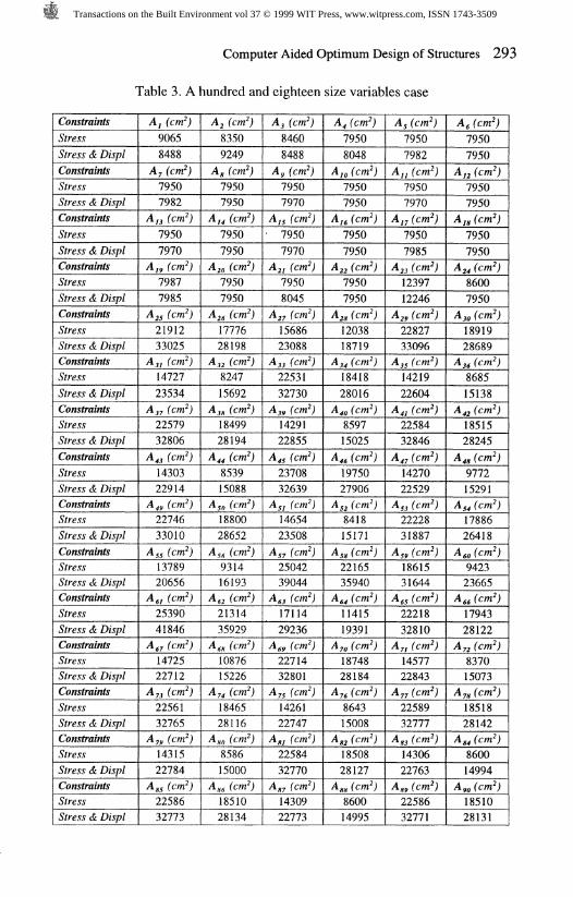
3) A hundred and eighteen areas: The distribution of area variables is indicatedin Figure 4c.For each design case two different problems were considered depending on
the class of constraints included:a) Stress constraints: Allowable stress level, Oy = -o^ = 2600 Kp/cnf.b) Displacement constraint: Maximum vertical displacement //250, being /
any span length.The optimum values of the objective function are presented in Figure 5.
2-
1 --
-Q- stress & displ. constraints-o- stress constraints
1.63
1.260.94
-t-118Number
of variablesFigure 5. Evolution of objective function values
Optimum values of the objective function and the set of design values foreach case appear in Tables 1 to 3.
Table 1. Four size variables case
Constraints
Stress
Stress & Displ
Ay fern')
9182
9231
A, fern';
27234
35620
A, (cm')
18660
24022
AXcm'j
14818
18536
W (fgMO*
1.28
1.63
Table 2. Eight size variables case
Constraints
Stress
Stress & Displ
Constraints
Stress
Stress & Displ
A, (cm")
10580
9142
A, (cm')
11414
18799
A, (cm')
7950
9296
A 7 (cnf)
13714
18800
A, fern")
25390
36577
A, fern")
9516
12401
A, fern")
21314
31937
W (Kg)* 10"
1.07
1.54
A, (cm')
17114
26575
Transactions on the Built Environment vol 37 © 1999 WIT Press, www.witpress.com, ISSN 1743-3509
Computer Aided Optimum Design of Structures 293
Table 3. A hundred and eighteen size variables case
ConstraintsStressStress & DisplConstraintsStressStress & DisplConstraintsStressStress & DisplConstraintsStressStress & DisplConstraintsStressStress & DisplConstraintsStressStress & DisplConstraintsStressStress & DisplConstraintsStressStress & DisplConstraintsStressStress & DisplConstraintsStressStress & DisplConstraintsStressStress & DisplConstraintsStressStress & DisplConstraintsStressStress & DisplConstraintsStressStress & DisplConstraintsStressStress & Displ
A, (cm")90658488
A, (cm")79507982
A,, (cm")79507970
Ajy (cm*)79877985
A# fern")2191233025
A 3, (cm*)1472723534
A,; (cm")2257932806
A,, (cm")1430322914
A,, (cm")2274633010
A,, (cm")1378920656
A,, (cm";2539041846
A,; (Cm")1472522712
A 7, (cm*)2256132765
A,, (cm")1431522784
A,, (cm")2258632773
A, (cm")83509249
A, (cm")79507950
A,, (cm")79507950
A,, (cm')79507950
A,, (cm")1777628198
A,, (cm?)824715692
A,* (cm*)1849928194
A,, (cm")853915088
A so (cm*)1880028652
A,, (cm")931416193
A,, (cm")2131435929
AM (cm")1087615226
A,, (cm")1846528116
A** (cm")858615000
AM (cm")1851028134
L A, (cm")84608488
Ay (cm")79507970
A,, (cm")• 7950
7970A,, (cm")79508045
A,; (cm")1568623088
A,, (cm")2253132730
A,, (cm")1429122855
A,, (cm")2370832639
A,, (cm")1465423508
A,; (cm")2504239044
A,, (cm")1711429236
A«y (cm")2271432801
A;, (cm")1426122747
A,, (cm")2258432770
A,; (cm")1430922773
A, (cm")79508048
A™ fern")79507950
A,, (cm")79507950
A,, (cm")79507950
A,, (cm")1203818719
A,, (cm")1841828016
A,, (cm")859715025
A,, (cm")1975027906
A,, (cm")841815171
A,, (cm")2216535940
A,, (cm")1141519391
A?, (cm")1874828184
A;, (cm")864315008
A,, (cm")1850828127
AM (cm")860014995
A, (cm")79507982
A,, (cm")79507970
A/7 (cm")79507985
A,, (cm")1239712246
A,, (cm")2282733096
A,, (cm")1421922604
A,, (cm")2258432846
A,7 (cm")1427022529
A,, (cm")2222831887
AM (cm")1861531644
A,5 (cm")2221832810
A,, (cm")1457722843
A 77 (cm")2258932777
A,, (cm")1430622763
A,, (cm")2258632771
A, (cm")79507950
A,, (cm")79507950
AM (cm")79507950
A,, (cm")86007950
A jo (cm")1891928689
A,, (cm")868515138
A,, (cm")1851528245
A,, (cm")977215291
A,, (cm")1788626418
A,, (cm")942323665
A,, (cm")1794328122
A* (cm")837015073
A 7* (cm")1851828142
A*, (cm")860014994
A,,, (cm")1851028131
Transactions on the Built Environment vol 37 © 1999 WIT Press, www.witpress.com, ISSN 1743-3509
294 Computer Aided Optimum Design of Structures
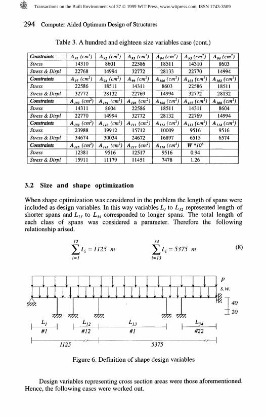
Table 3. A hundred and eighteen size variables case (cont.)
ConstraintsStressStress & DisplConstraintsStressStress & DisplConstraintsStressStress & DisplConstraintsStressStress & DisplConstraintsStressStress & Displ
Ayj (cm*)1431022768
Ayj (cm*)2258632772
A 103 ( )1431122770
A 109 (cm*)2398834674
AJJS (cm*)1238115911
Ay; (cm*)860114994
AM (cm*)1851128132
AJM (cm*)860414994
A jia (cm*)1991230034
A ii6 (cm*)951611179
AM (cm*)2258632772
Ayy (cm*)1431122769705 (cm*)2258632772
• in (cm*)1571224672
A,,7 (cm*)1251711451
A^ (cm1851128133
AJM (cm*)860314994
Aio6 (cm*)1851128132
A, ,2 (cm*)1000916897
Aj,s (cm*)95167478
A^ (cm*)1431022770
A,OJ (cm*)2258632772
AJM (cm*)1431122769
Aj,3 (cm*)95166515W*10*0.941.26
Ayt (cm*)860314994
4 102 (cm*)1851128132
A 108 (cm*)860414994
A, „ (cm*)95166574
3.2 Size and shape optimization
When shape optimization was considered in the problem the length of spans wereincluded as design variables. In this way variables L, to L^ represented length ofshorter spans and L,? to L^ corresponded to longer spans. The total length ofeach class of spans was considered a parameter. Therefore the followingrelationship arised.
12L; = 7725
34
%4 = (8)
i=13
II 1 r > . 1 ^
13 -34#12 #22
1125 ' 5375
Figure 6. Definition of shape design variables
40
20
Design variables representing cross section areas were those aforementioned.Hence, the following cases were worked out.
Transactions on the Built Environment vol 37 © 1999 WIT Press, www.witpress.com, ISSN 1743-3509

Computer Aided Optimum Design of Structures 295
Table 4. Number of design variables
Span length
343434
Cross sec
1
tion areas
4818
Total
3842152
Again, an optimization problem considering only stress constraints andanother problem including also vertical displacement constraints were carried out.In both cases the constraint bounds were those mentioned in the sizeoptimization problem.
Evolution of the objective function with regards to the number of designvariables is presented in Figure 7.
.70*1
7 0.93t-
0.910.84
-o- stress & displ constraints-o- stress constraints
0.83
0.81 0.80
750Number
of variablesFigure 7. Evolution of objective function values
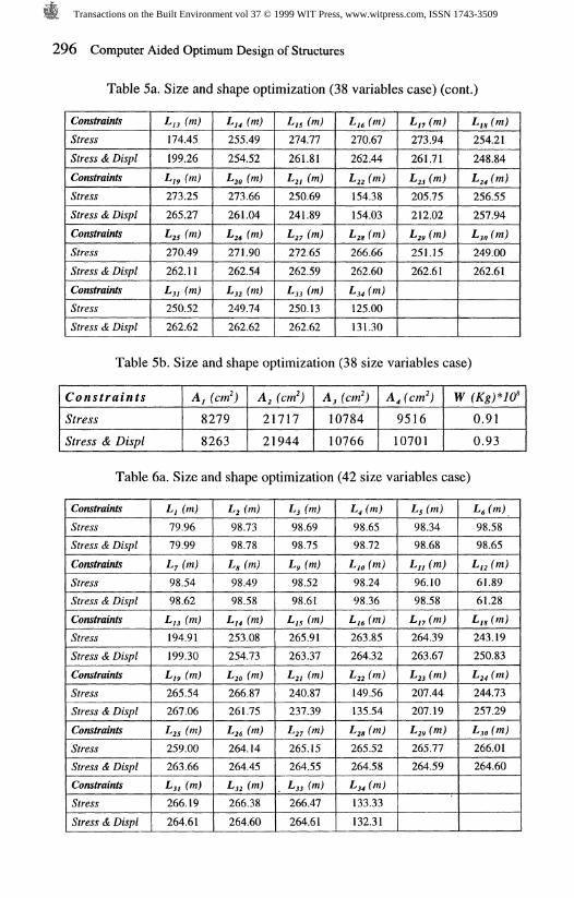
Values of objective function, cross section areas and span length appear foreach case in Tables 5 to 7.
Table 5a. Size and shape optimization (38 variables case)
Constraints
StressStress & DisplConstraintsStressStress & Displ
LI (m)
80.7780.76L,(m)98.7698.57
Lt(m)98.7698.73Lg (m)98.7798.52
Lj(m)98.7798.67L,(m)98.4798.54
L<(m)98.7698.66L,o (m)96.6498.23
Lg(m)98.7798.63Lj, (m)95.1096.31
Lg(m)98.7798.59LU (m)62.6660.70
Transactions on the Built Environment vol 37 © 1999 WIT Press, www.witpress.com, ISSN 1743-3509
296 Computer Aided Optimum Design of Structures
Table 5a. Size and shape optimization (38 variables case) (cont.)
ConstraintsStressStress & Displ
ConstraintsStressStress & DisplConstraintsStressStress & DisplConstraintsStressStress & Displ
L,3 (m)174.45199.26
Ljy (m)273.25265.27
^25 M270.49262.11
LJI (m)250.52262.62
LU (m)255.49254.52
620 (m)273.66261.04
J-26 (m)271.90262.54
LU M249.74262.62
LJS (m)274.77261.81
LZJ (m)250.69241.89L (m)272.65262.59L (m)250.13262.62
LU (m)270.67262.44
£22 W154.38154.03
&24 )266.66262.60
6,4 (m)125.00131.30
LU (m)273.94
261.71
1-23 (m)205.75212.02
£j, (m)251.15262.61
Ljg (m)254.21248.84
1 24 W256.55257.94LM (m)249.00262.61
Table 5b. Size and shape optimization (38 size variables case)
Constraints
Stress
Stress & Displ
A, (W)
8279
8263
A, fern')
21717
21944
A, fcm')
10784
10766
AXcm'j
9516
10701
W (Kg)* 10*
0.91
0.93
Table 6a. Size and shape optimization (42 size variables case)
ConstraintsStressStress & DisplConstraintsStressStress & DisplConstraintsStressStress & DisplConstraintsStressStress & DisplConstraintsStressStress & DisplConstraintsStressStress & Displ
L,(m)79.9679.99Ly(m)98.5498.62
Lj3 (m)194.91199.30LM (m)265.54267.06
£25 M259.00263.66
LSI (™)266.19264.61
L,(m)98.7398.78
4, M98.4998.58Lj4 (m)253.08254.73
LZO M266.87261.75L (m)264.14264.45
Lj2 (m)266.38264.60
Lttm)98.6998.75
L,(m)98.5298.61LJS (m)265.91263.37LU (m)240.87237.39
4,7 M265.15264.55LJS (m)266.47264.61
L<(m)98.6598.72
LH, (m)98.2498.36Ljt (m)263.85264.32
^22 M149.56135.54
Z/2* (rn)265.52264.58Lj4 (m)133.33132.31
L,(m)98.3498.68LU (m)96.1098.58L,7 (m)264.39263.67
L23 (m)207.44207.19
Lf9 (m)265.77264.59
L,(m)98.5898.65
Lj2 (rn)61.8961.28Ljg (m)243.19250.83
L24 (m)244.73257.29
Lj,, (m)266.01264.60
Transactions on the Built Environment vol 37 © 1999 WIT Press, www.witpress.com, ISSN 1743-3509

Computer Aided Optimum Design of Structures 297
Table 6b. Size and shape optimization (42 size variables case)
ConstraintsStressStress & DisplConstraintsStressStress & Displ
A, (cm")83488355
A, (cm")915811375
A, (cm*)79507950
A 7 (cm*)1070010700
A, (cm")2086022064A, ("%")1070010700
A, (cm")1408713910
W(Kg)*10*0.810.84
A, (cm")103479997
Table 7a. Size and shape optimization (152 variables case)
ConstraintsStressStress & DisplConstraintsStressStress & DisplConstraintsStressStress & DisplConstraintsStressStress & DisplConstraintsStressStress & DisplConstraintsStressStress & Displ
Lj(m)80.2080.94Lj(m)98.5696.37LJI (m)194.19208.99Ljy (m)263.33261.80£25 M259.37258.09LSI (m)266.20264.92
L,(m)98.5698.65L,(m)98.4193.71LU M256.14250.06&2o (m)261.15258.441 26 W262.96261.90Lj2 M266.32264.40
Lj(m)98.6899.59L,(m)98.9393.45LJS (m)264.10259.36l-2i (m)243.24246.791 27 M264.86263.68Lj3 (m)266.40264.04
L<(m)98.5997.80Lm (m)96.4293.14Ljg (m)264.44260.85J-22 (m)152.35165.69LZS (m)265.22264.59L (m)133.29131.96
L;(m)98.6098.41LJ, (m)95.8292.44Lj7 (m)263.14259.791 23 (m)206.60204.34&2P (m)265.66265.04
L<(m)98.5796.19Lj2 (m)63.6484.32L,g (m)243.81246.75L24 (m)246.28248.35LJO (m)265.95265.17
Table 7b. Size and shape optimization (152 variables case)
ConstraintsStressStress & DisplConstraintsStressStress & DisplConstraintsStressStress & DisplConstraintsStressStress & DisplConstraintsStressStress & Displ
Ay (cm")83668431
A 7 (cm*)83438275
A,, (cm")83478138
A,, (cm")82057950
A,, (cm*)2045119411
A, (cm")79507951
A, (cm*)79507950
A,, (cm")79507950
A,, (cm")79507950
A,, (cm")1367812959
A, fcm^83328344
A, (cm83468300
A,, fern";83497950
A,, (cm?)82787950
A,; (cm")1039410371
A, (cm")79507950
A/o (cm*)79507950
A,, (cm")79507950
A,, (cm")79507950
A,, (cm")899710984
A, (cm")83478394
A/; (cm*)83478146
A,; (cm")83457950
A,, (cm*)828710406
A,, (cm*)2061922280
A, (cm")79507950
A,, (cm")79507950
Ajy (cm*)79507950
A*, (cm")79507950
A,, (cm")1402613459
Transactions on the Built Environment vol 37 © 1999 WIT Press, www.witpress.com, ISSN 1743-3509

298 Computer Aided Optimum Design of Structures
Table 7b. Size and shape optimization (152 variables case) (cont.)
ConstraintsStressStress & DisplConstraintsStressStress & DisplConstraintsStressStress & DisplConstraintsStressStress & DisplConstraintsStressStress & DisplConstraintsStressStress & DisplConstraintsStressStress & DisplConstraintsStressStress & DisplConstraintsStressStress & DisplConstraintsStressStress & Displ8627StressStress & DisplConstraintsStressStress & DisplConstraintsStressStress & DisplConstraintsStressStress & DisplConstraintsStressStress & Displ
A,/ (cm97958716
A,, (cm")2074622703
A,, (cm*)98938509
A 4, (cm*)2074122111
ASS (cm*)98458530
A,, (WV2054721151
A,7 (cm*)1030810551
Anfwfj2067422226
A%, (cm*)96468651
A,, (cm2080422672
Ayj (cm*)98508627
A^ (cm*)2088122827
A, M (cm*)99548562
Aj (cm*)2086522750
A us (cm*)1070010700
A,, (WJ903211125
A,, (cm*)1398813527
A« (cm*)897711204
A ;„ (cm*)1404013659
AS, (cm*)887311166
A,, (cm*)1378014208
A,, (cm*)895710959
Aj4 (cm*)1404813614
Ago (cm*)878011348
A,, (cm1404013721
AM (cm*)899611355
AM (cm*)1404413682
A, 04 (cm*)904911294
Ajjo (cm*)1404013633
A,,, (cm*)1070010700
A,, (Wj2070222671
A,, (cm98348484
A,, (cm*)2087522039
ASJ (cm*)9650
• 8658A,? (cm*)2039222847
A,, (cm')1041811409
A,, (cm*)2033421785
A 75 (cm*)97468662
AW (cm*)2078522586
A*7 (cm*)97938637
A,, (cm*)2086122792
AM (cm*)99278584
A jos (cm*)2087922776
AJU (cm*)101128553
AH, (cm*)1070010700
A,, (cm2j1395313550
A,,, (cm*)891111219
A,, (cm*)1407213558
A,, (cm888611253
AS, (cm*)1404213505
A,, (cm*)87948935
A 70 (cm*)1371913454
A;, (cm877211302
A,, (cm1403613712
AM (cm*)896111362
A,, (cm1404513709
Ajoo (cm*)902511320
A 106 (cm*)1403613639
A//2 (cm*)907611279
Ajjg (cm*)1070010700
A,, (cm98288562
A,, (cm*)2080622521
A,7 (cm*)98778634
A,, (cm*)2060922438
Asy (cm*)100498875
A,, (c m')2034519504
A,, (cm*)98168723
A 77 (cm*)2070522451
A,, (cm97138645
Agy (cm*)2084022736
A,, (cm*)98968611
AJOJ (cm*)2089222773
A/07 (cm*)99398554
AH; (cm*)1070010700W*70*0.800.83
A,, (cm*)901911230
A*, (cm*)1404213520
A,, (cm*)901911410
As4 (cm*)1392213499
A*, (cm*)890011137
A 66 (cm*)1371813116
A 72 (cm*)868711165
A;, (cm1402013683
A,, (cm900511363
Ayo (cm*)1404513720
Aye (cm*)900511342
A/w (cm*)1403413654
AIM (cm*)904811282
A 1 14 (cm*)1070010700
Transactions on the Built Environment vol 37 © 1999 WIT Press, www.witpress.com, ISSN 1743-3509

Computer Aided Optimum Design of Structures 299
4 Conclusions
Some conclusions may be obtained from the results presented in the paper.— Size optimization of long civil engineering structures produces a quite
important reduction on structural weight without complicating theconstruction process.
— Optimum design of frame structures has been made frequently, butapplications taking in account changes on geometry are scarce.
— Shape optimization of bridges produce even further advantages that thoseobtained by size optimization. Introducing spans length as design variablesallows the material to be distributed along the bridge in a more efficientway.
— For the example posed, optimal design with size and shape design variablesleads to almost the same solution, in terms of the structural weight, forstress constraints that for stress and displacement constraints.
5 References
1. COHN, M.Z., GHOSH, S.K. and PARIMI, S.R., "Unified Approach tothe Theory of Plastic Structures", /. Eng. Mech. Div., ASCE, vol. 98, No.EM5, October 1972, pp. 1133-1158.
2. HORNE, M.R. and MORRIS, L.I., Optimum Design of Multistory RigidFrames, in Optimum Structural Design, Gallagher, R.H. (ed), John Wiley,1973.
3. KAVLIE, D. and MOE, J., "Automated Design of Frame Structures", J.Struc. Div., ASCE, vol. 97, No. ST1, January 1971, pp. 33-62.
4. MOSES, F. and ONODA, S., "Minimum Weight Design of Structureswith Application to Elastic Grillages", Int. J. Num. Meth. Eng., vol. 1,pp. 311-331, 1969.
5. KAVLIE, D. and MOE, J., "Application of Nonlinear Programming toOptimum Grillage Design with Nonconvex Sets of Variables", Int. J.Num. Meth. Eng., vol. 1, pp. 351-378, 1969.
6. HERNANDEZ, S., Size and Shape Optimization of Truss and FrameStructures with Multiple Local Optima. 33rd AIAA/ASME/ASCE/AHS/ASC Structures, Structural Dynamics and Materials Conference. Dallas(USA), 1992.
7. GRIERSON, D.E., Computer-Automated Optimal Design of StructuralSteel Frameworks, in "Optimization and Artificial Intelligence in Civil andStructural Engineering", B.H.V. Topping (ed.), pp. 327-354, KluwerAcademic Publishers, 1992.
Transactions on the Built Environment vol 37 © 1999 WIT Press, www.witpress.com, ISSN 1743-3509

300 Computer Aided Optimum Design of Structures
8. GRIERSON, D.E. and XU, L., Design Optimization of Steel FrameworksAccounting for Semi-Rigid Connections, in "Optimization of LargeStructural Systems", G.I.N. Rozvany (ed.), pp. 873-882, Kluwer AcademicPublishers, 1992.
9. ADELI, H. and CHENG, N.T., "Concurrent Genetic Algorithms forOptimization of Large Structures", Journal of Aerospace Engineering,ASCE, Vol. 7, No. 3, pp. 276-296, 1994.
10. ADELI, H. and PARK, H.S., "A Neural Dynamics Model for StructuralOptimization - Theory". Computers and Structures, Vol. 57, No. 3, pp.383-390, 1995.
11. ADELI, H. and PARK, H.S., "Optimization of Space Structures by NeuralDynamics", Neural Networks, Vol. 8, No. 5, pp. 769-781, 1995.
12. SOBIESCZANSKI-SOBIESKI, J., Multilevel Structural Optimization,Computer Aided Optimal Design, NATO/ASI Seminar, Vol. 3, pp. 7-28,1986.
13. KIM, D., Multilevel-Multiobjective Optimization for EngineeringSynthesis, Ph. D. Thesis, University of California in Santa Barbara, 1989.
14. ADS User's Manual, VR&D, 1988.
15. GILMOUR, R., SAUVAGEOT, G. TASSIN, D. and LOCKWOOD, J.D.,Northumberland's Ice Breaker. Civil Engineering, pp. 34-38, ASCE,January 1997.
16. DUPRE, J., Bridges. Black Dog & Leventhal, 1997.
Transactions on the Built Environment vol 37 © 1999 WIT Press, www.witpress.com, ISSN 1743-3509