jeep chevy ford dodge toyota - 3” suspension …bds-suspension.com/instructions/014303.pdf6 |...
TRANSCRIPT

3” Suspension System
Jeep Wrangler, TJ, Rubicon/Unlimited 4WD | 2003-2006
Rev. 022718
Part#: 014303
491 W. Garfield Ave., Coldwater, MI 49036 . Phone: 517-279-2135E-mail: [email protected]

2 | 014303
Read And Understand All Instructions And Warnings Prior To Installation Of
System And Operation Of Vehicle.
BEFORE YOU STARTBDS Suspension Co. recommends this system be installed by a professional technician. In addition to these instructions, professional knowledge of disassembly/ reassembly procedures and post installation checks must be known.
FOR YOUR SAFETYCertain BDS Suspension products are intended to improve off-road performance. Modifying your vehicle for off-road use may result in the vehicle handling differently than a factory equipped vehicle. Extreme care must be used to prevent loss of control or vehicle rollover. Failure to drive your modified vehicle safely may result in serious injury or death. BDS Suspension Co. does not recommend the combined use of suspension lifts, body lifts, or other lifting devices. You should never operate your modified vehicle under the influence of alcohol or drugs. Always drive your modified vehicle at reduced speeds to ensure your ability to control your vehicle under all driving conditions. Always wear your seat belt.
BEFORE INSTALLATION• Special literature required: OE Service Manual for model/year
of vehicle. Refer to manual for proper disassembly/reassembly procedures of OE and related components.
• Adhere to recommendations when replacement fasteners, retainers and keepers are called out in the OE manual.
• Larger rim and tire combinations may increase leverage on suspension, steering, and related components. When selecting combinations larger than OE, consider the additional stress you could be inducing on the OE and related components.
• Post suspension system vehicles may experience drive line vibrations. Angles may require tuning, slider on shaft may require replacement, shafts may need to be lengthened or trued, and U-joints may need to be replaced.
• Secure and properly block vehicle prior to installation of BDS Suspension components. Always wear safety glasses when using power tools.
• If installation is to be performed without a hoist, BDS Suspension Co. recommends rear alterations first.
• Due to payload options and initial ride height variances, the amount of lift is a base figure. Final ride height dimensions may vary in accordance to original vehicle attitude. Always measure the attitude prior to beginning installation.
BEFORE YOU DRIVECheck all fasteners for proper torque. Check to ensure for adequate clearance between all rotating, mobile, fixed, and heated members. Verify clearance between exhaust and brake lines, fuel lines, fuel tank, floor boards and wiring harness. Check steering gear for clearance. Test and inspect brake system.
Perform steering sweep to ensure front brake hoses have adequate slack and do not contact any rotating, mobile or heated members. Inspect rear brake hoses at full extension for adequate slack. Failure to perform hose check/ replacement may result in component failure. Longer replacement hoses, if needed can be purchased from a local parts supplier.
Perform head light check and adjustment.
Re-torque all fasteners after 500 miles. Always inspect fasteners and components during routine servicing.
Your truck is about to be fitted with the best suspension system on the market today. That means you will be driving the baddest looking truck in the neighborhood, and you’ll have the warranty to ensure that it stays that way for years to come.
Thank you for choosing BDS Suspension!
33x12.50 Tire15 x 8 and 3-3/4” Backspace Wheel

014303 | 3
014303 Box Kit
Part # Qty Description
034302 2 Front Coil Springs
034308 2 Rear Coil Springs
911104 2 Rear Sway Bar Link
01326 1 Rear Track Bar Bracket
2296 2 2" x 2" Tall Rear Bump Stop Spacer
3296 2 3" x 2" Tall Front Bump Stop Spacer
823801 2 Front LCA Cam Bolt Kit
B987 1 Bag Kit - Jeep TJ
439 1 Bolt Pack - Front Bump Stop Hardware2 3/8"-16 x 2-1/2" bolt grade 5 clear zinc
2 3/8" USS flat washer clear zinc
1 3/8"-16 x 1" self-tapping bolt hex head type 23
709 1 Bolt Pack - Rear Sway Bar Link Hardware4 10mm-1.50 x 60mm bolt grade 10.9 clear zinc
4 10mm-1.50 prevailing torque nut clear zinc
8 3/8" USS flat washer clear zinc
711 1 Bolt Pack2 5/16"-18 x 7/8" bolt grade 5 clear zinc
2 5/16-18 prevailing torque nut clear zinc
2 5/16" USS washer clear zinc
4 5/16" SAE washer clear zinc
1 3/8"-16 x 1" bolt grade 5 clear zinc
1 3/8"-16 prevailing torque nut clear zinc
2 12mm-1.75 x 80mm bolt class 10.9 clear zinc
2 12mm-1.75 prevailing torque nut clear zinc
4 1/2" SAE washer clear zinc
65077 1 1/8" Cotter Pin
SB58BK 4 Hourglass Bushing
45313 4 5/8" x 10mm ID Sleeve
54587 1 Rear Track Bar Spacer Sleeve
B1080G5 2 10mm x 80mm Bolt
014303 Box Kit (Cont’d)
Part # Qty Description
B1235 1 Bag Kit - Sway Bar Disconnect Hardware
03029 2 Sway Bar Disconnect Sleeves
03005 2 Quick Pins
M03212-BK 2 Poly Spacers
A1046 2 Sway Bar Disconnect Stud - Assembly
03013 2 Stainless Steel Disconnect Post
37130 2 1/2"-20 Fine Nut
03014 2 Storage Post
03012 2 Sway Bar Clevis Bracket
33859 2 3/8" Washer
23259 2 5/16"-18 x 1-1/2" SHCS Bolt
10598-00499 2 10mm x 35mm BHSCS
10598-01212 2 10mm x 50mm BHSCS
40167 2 10mm Nylock Nut
40515 2 10mm Lock Washer
342702 2 Loc-Tite Pouch
A1024 2 Sway Bar Link Assembly
03010 1 Female - Long
03011 1 Male - Long
M00475-BK 2 Spherical Bushing
7050R 2 Grease Zerk Cap
7607 2 Grease Zerk
36264 1 5/8" Jam Nut
JKS11521 1 JKS Sticker

4 | 014303
INSTALLATION INSTRUCTIONS1. Park the vehicle on a clean, flat surface and block the rear wheels
for safety.
2. Measure from the center of the wheel up to the bottom edge of the wheel opening
LF______ RF______ LR______ RR______
3. Remove the forward transmission skid plate. Remove the two frame mount bolts (one per side) and three center skid plate bolts. Remove skid plate from vehicle. As a result of the increased suspension travel obtained by the addition of this suspension system, the forward transmission skid plate cannot be reinstalled. Installation of this skid plate will result in contact between the front driveshaft and skid plate crossmember throughout normal suspension travel, possibly damaging the driveshaft.
FRONT INSTALLATION4. Disconnect the front track bar from the passenger’s side of the front axle (Fig 1). Retain hardware.
FIGURE 1
5. Raise the front of the vehicle and support with jack stands at the frame rails just behind the lower control arm pockets.
6. Support the front axle with a hydraulic jack.
7. Remove the wheels.
8. Remove the OE shocks. Discard the shocks and upper mounting hardware. Retain the lower mounting bolts/nuts.
Drill and standard size drill bit set
TROUBLESHOOTING INFORMATION FOR YOUR VEHICLE1. Stabilizer and front lower control arms are highly recommended.
014303 | 5
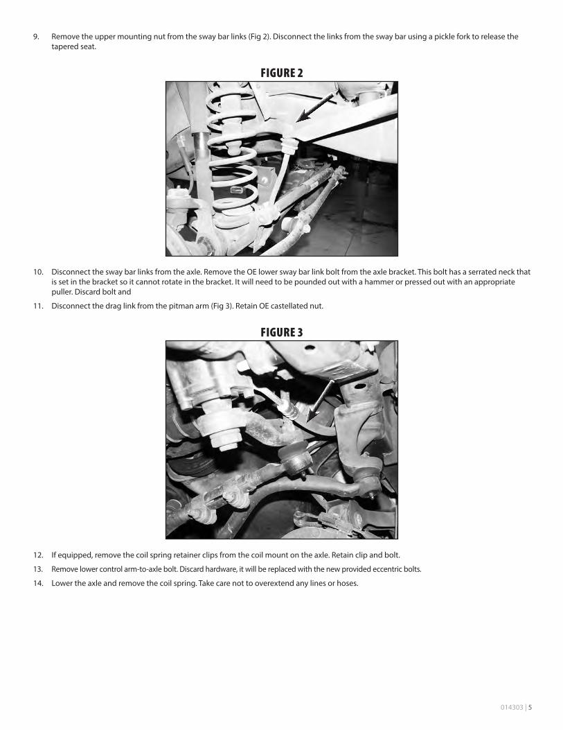
9. Remove the upper mounting nut from the sway bar links (Fig 2). Disconnect the links from the sway bar using a pickle fork to release the tapered seat.
FIGURE 2
10. Disconnect the sway bar links from the axle. Remove the OE lower sway bar link bolt from the axle bracket. This bolt has a serrated neck that is set in the bracket so it cannot rotate in the bracket. It will need to be pounded out with a hammer or pressed out with an appropriate puller. Discard bolt and
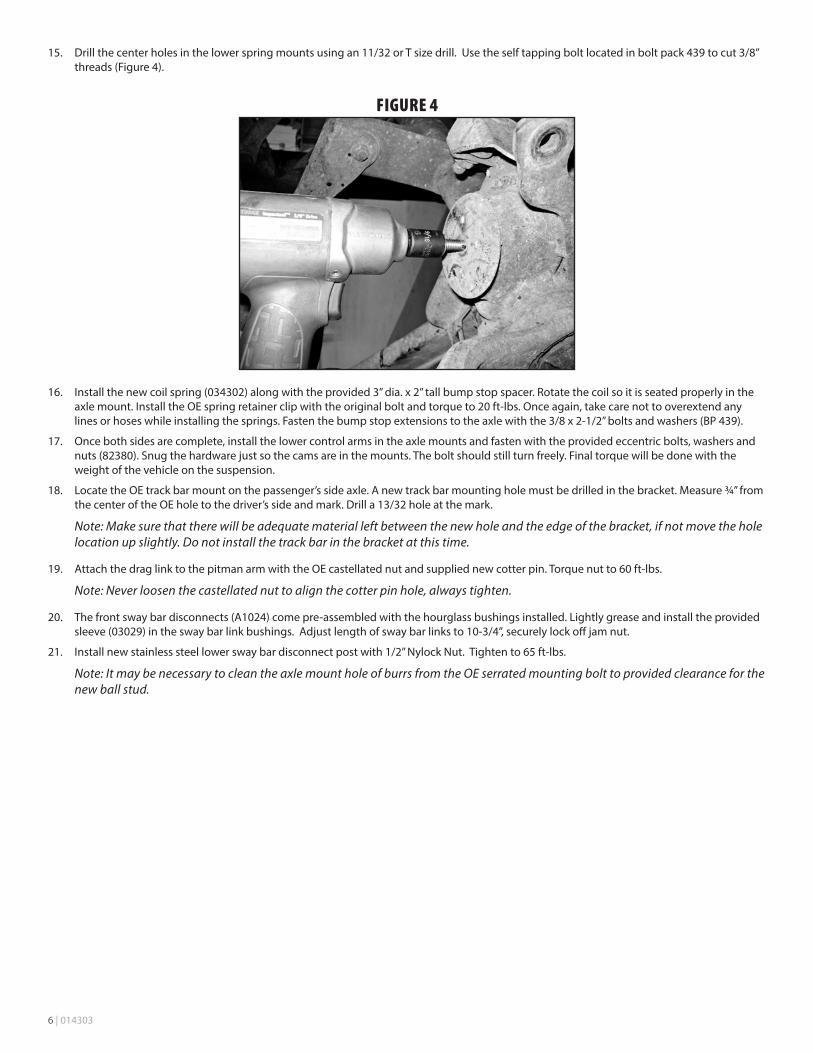
11. Disconnect the drag link from the pitman arm (Fig 3). Retain OE castellated nut.
FIGURE 3
12. If equipped, remove the coil spring retainer clips from the coil mount on the axle. Retain clip and bolt.
13. Remove lower control arm-to-axle bolt. Discard hardware, it will be replaced with the new provided eccentric bolts.
14. Lower the axle and remove the coil spring. Take care not to overextend any lines or hoses.
6 | 014303
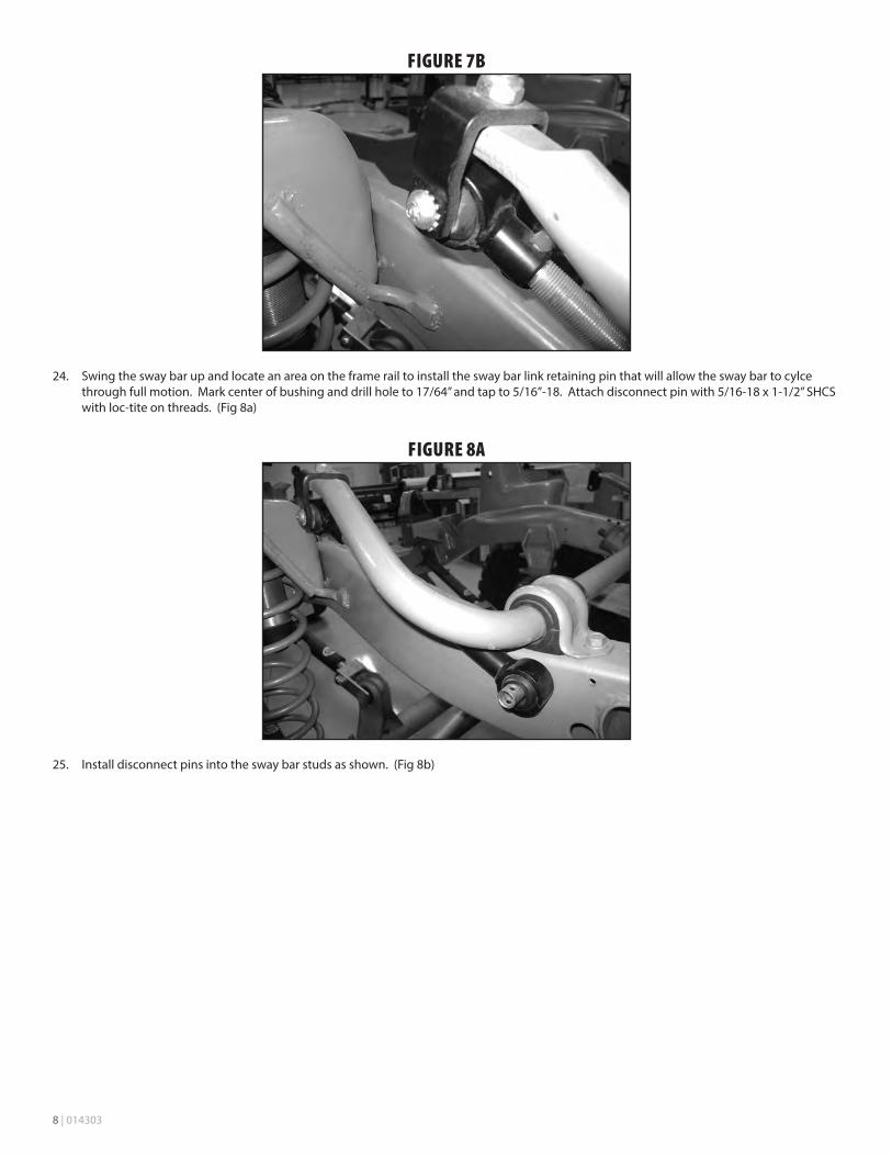
15. Drill the center holes in the lower spring mounts using an 11/32 or T size drill. Use the self tapping bolt located in bolt pack 439 to cut 3/8” threads (Figure 4).
FIGURE 4
16. Install the new coil spring (034302) along with the provided 3” dia. x 2” tall bump stop spacer. Rotate the coil so it is seated properly in the axle mount. Install the OE spring retainer clip with the original bolt and torque to 20 ft-lbs. Once again, take care not to overextend any lines or hoses while installing the springs. Fasten the bump stop extensions to the axle with the 3/8 x 2-1/2” bolts and washers (BP 439).
17. Once both sides are complete, install the lower control arms in the axle mounts and fasten with the provided eccentric bolts, washers and nuts (82380). Snug the hardware just so the cams are in the mounts. The bolt should still turn freely. Final torque will be done with the weight of the vehicle on the suspension.
18. Locate the OE track bar mount on the passenger’s side axle. A new track bar mounting hole must be drilled in the bracket. Measure ¾” from the center of the OE hole to the driver’s side and mark. Drill a 13/32 hole at the mark.
Note: Make sure that there will be adequate material left between the new hole and the edge of the bracket, if not move the hole location up slightly. Do not install the track bar in the bracket at this time.
19. Attach the drag link to the pitman arm with the OE castellated nut and supplied new cotter pin. Torque nut to 60 ft-lbs.
Note: Never loosen the castellated nut to align the cotter pin hole, always tighten.
20. The front sway bar disconnects (A1024) come pre-assembled with the hourglass bushings installed. Lightly grease and install the provided sleeve (03029) in the sway bar link bushings. Adjust length of sway bar links to 10-3/4”, securely lock off jam nut.
21. Install new stainless steel lower sway bar disconnect post with 1/2” Nylock Nut. Tighten to 65 ft-lbs.
Note: It may be necessary to clean the axle mount hole of burrs from the OE serrated mounting bolt to provided clearance for the new ball stud.

014303 | 7
FIGURE 6
22. Install the provided upper u-bracket (03012) to the TOP side of the sway bar with the threaded end towards the center of the vehicle. Attach with 10mm x 35mm hardware. Square the bracket up to the frame and tighten to 40 ft-lbs. (Fig 7a)
FIGURE 7A
23. Install the sway bar link assembly to the upper u-bracket with the provided10mm x 50mm button head bolt with loc-tite on threads and external tooth lock washer. (Fig 7b)
8 | 014303
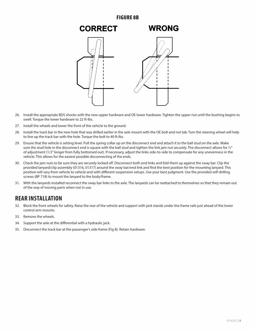
FIGURE 7B
24. Swing the sway bar up and locate an area on the frame rail to install the sway bar link retaining pin that will allow the sway bar to cylce through full motion. Mark center of bushing and drill hole to 17/64” and tap to 5/16”-18. Attach disconnect pin with 5/16-18 x 1-1/2” SHCS with loc-tite on threads. (Fig 8a)
FIGURE 8A
25. Install disconnect pins into the sway bar studs as shown. (Fig 8b)
014303 | 9
FIGURE 8B
26. Install the appropriate BDS shocks with the new upper hardware and OE lower hardware. Tighten the upper nut until the bushing begins to swell. Torque the lower hardware to 22 ft-lbs.
27. Install the wheels and lower the front of the vehicle to the ground.
28. Install the track bar in the new hole that was drilled earlier in the axle mount with the OE bolt and nut tab. Turn the steering wheel will help to line up the track bar with the hole. Torque the bolt to 40 ft-lbs.
29. Ensure that the vehicle is setting level. Pull the spring collar up on the disconnect end and attach it to the ball stud on the axle. Make sure the stud hole in the disconnect end is square with the ball stud and tighten the link jam nut securely. The disconnect allows for ½” of adjustment (1/2” longer from fully bottomed out). If necessary, adjust the links side-to-side to compensate for any unevenness in the vehicle. This allows for the easiest possible disconnecting of the ends.
30. Check the jam nuts to be sure they are securely locked off. Disconnect both end links and fold them up against the sway bar. Clip the provided lanyard/clip assembly (01316, 01317) around the sway bar/end link and find the best position for the mounting lanyard. This position will vary from vehicle to vehicle and with different suspension setups. Use your best judgment. Use the provided self-drilling screws (BP 718) to mount the lanyard to the body/frame.
31. With the lanyards installed reconnect the sway bar links to the axle. The lanyards can be reattached to themselves so that they remain out of the way of moving parts when not in use.
REAR INSTALLATION32. Block the front wheels for safety. Raise the rear of the vehicle and support with jack stands under the frame rails just ahead of the lower
control arm mounts.
33. Remove the wheels.
34. Support the axle at the differential with a hydraulic jack.
35. Disconnect the track bar at the passenger’s side frame (Fig 8). Retain hardware.

10 | 014303
FIGURE 8
36. Remove the OE rear shocks. Retain the upper and lower mounting hardware.
37. Remove the OE sway bar links (Fig 9). The links will not be reused.
FIGURE 9
38. Disconnect the lower control arms from the axle. Retain hardware.
39. Lower the axle until the coil springs can be removed. Take care not to over-extend any lines or hoses.
40. Remove the OE rubber bump stop from the upper coil mount. Large pliers can be used to pull it out. Remove the OE bump stop retainer cup by remove the bolt from the center of the cup.

014303 | 11
41. Install the provided bump stop spacer (2296) between the OE retainer cup and the frame with a 10mm x 80mm bolt. Use Loctite on the bolt threads and torque to 30 ft-lbs. Install the OE bump stop in the retainer cup (Fig 10).
Note: A small amount of grease will ease installation of the bump stop.
FIGURE 10
42. Remove the plastic cover from the track bar mount on the driver’s side of the axle (Fig 11). Discard the cover.
FIGURE 11
43. Disconnect the track bar (Fig 10) from the axle by remove the Torx head bolt (T55). Note how the track bar is positioned in vehicle. It can rest in the vehicle or be removed for reinstallation later.

12 | 014303
44. Position the supplied track bar relocation bracket (01326) on the original track bar axle mount (Fig 12). Install the supplied 1.600” long sleeve (6-1) in the original track bar mounting point (Fig 13). Install a 12mm x 80mm bolt and 7/16” washer (BP 711) through the supplied bracket, OE mount, sleeve and out through the other side of the mount. Loosely fasten the bolt with the OE nut tab.
Note: If the nut tab is damaged use a provided 12mm nut (BP 711).
FIGURE 12
FIGURE 13
45. Using the new bracket as a template, mark the two additional mounting holes to be drilled. Note: The lowest hole in the bracket will line up with an existing hole that may need to be widened slightly.
46. Remove the bracket and drill 5/16” holes at the top two marks and widen the lower hole, if necessary, to accept the 3/8” bolt.
47. Reinstall the bracket as instructed before in addition to install the provided 5/16” x 1” bolts, nuts and washers (BP 711) in the upper two newly drilled mounting holes and the 3/8” x 1” bolt, nut and washers (BP 711) in the lower hole. Leave hardware loose until all bolts are installed.
48. Torque all mounting bolts: 12mm hardware- 60 ft-lbs, 3/8” hardware- 30 ft-lbs, 5/16” hardware- 15 ft-lbs.
49. Install the track bar in the new track bar bracket with the provided 12mm x 80mm bolt, nut and 7/16” USS washers. Be sure to run the bolt from back to front. Leave bolt loose at this time.
50. Install the provided new coil springs (034308).
51. Install the appropriate BDS shocks OE upper and lower hardware. Torque the lower hardware to 60 ft-lbs. Torque the upper hardware to 22 ft-lbs.
52. Reinstall the lower control arms in the axle mounts with the OE hardware. Leave hardware loose.
53. The new rear sway bar links (911104) come with the bushings already installed. Lightly grease and install the provided sleeves (45313) in each of the bushings.
014303 | 13
54. Install the rear sway bar links to the original frame mount and the sway bar with the provided 10mm x 60mm bolts, nut and washers (BP 709). Torque the bolts to 30 ft-lbs. The OE 10mm nut tab can be reused at the frame.
55. Install the wheels and lower the vehicle to the ground.
Note: Make sure the track bar doesn’t get pitched when lowering the vehicle.
56. Torque the lower control arm bolts at the axle to 125 ft-lbs.
57. Attach the track bar to the original frame mount with the OE hardware. The body may need to be shifted slightly side-to-side to align the bolt. Torque both upper and lower track bar bolts to 60 ft-lbs.
POST INSTALLATION58. Check the vehicle for any interference of any moving parts. Check all brake and fuel lines. Perform a steering sweep to ensure full turning
radius without interference.
59. Double check all fasteners for proper torque.
60. Install warning card rear view mirror for vehicle operator.
61. A complete front end alignment should be performed after the installation of this kit. A head light adjustment should also be performed.
62. The steering wheel can be centered by adjusting the front steering center link.
63. Check all fasteners after 500 miles.
Thank you for choosing BDS Suspension.For questions, technical support and warranty issues relating to this BDS Suspension product, please contact your distributor/installer
before contacting BDS Suspension directly.