ji-guang zhang wu xu wesley a. henderson lithium metal ... series in materials... · the use of...
TRANSCRIPT

Springer Series in Materials Science 249
Ji-Guang ZhangWu XuWesley A. Henderson
Lithium Metal Anodes and Rechargeable Lithium Metal Batteries
Springer Series in Materials Science
Volume 249
Series editors
Robert Hull, Charlottesville, USAChennupati Jagadish, Canberra, AustraliaYoshiyuki Kawazoe, Sendai, JapanRichard M. Osgood, New York, USAJürgen Parisi, Oldenburg, GermanyTae-Yeon Seong, Seoul, KoreaShin-ichi Uchida, Tokyo, JapanZhiming M. Wang, Chengdu, China

The Springer Series in Materials Science covers the complete spectrum of materialsphysics, including fundamental principles, physical properties, materials theory anddesign. Recognizing the increasing importance of materials science in future devicetechnologies, the book titles in this series reflect the state-of-the-art in understandingand controlling the structure and properties of all important classes of materials.
More information about this series at http://www.springer.com/series/856
Ji-Guang Zhang • Wu XuWesley A. Henderson
Lithium Metal Anodesand Rechargeable LithiumMetal Batteries
123
Ji-Guang ZhangEnergy and Environment DirectoratePacific Northwest National LaboratoryRichland, WAUSA
Wu XuEnergy and Environment DirectoratePacific Northwest National LaboratoryRichland, WAUSA
Wesley A. HendersonU.S. Army Research Office (ARO)Research Triangle Park, NCUSA
ISSN 0933-033X ISSN 2196-2812 (electronic)Springer Series in Materials ScienceISBN 978-3-319-44053-8 ISBN 978-3-319-44054-5 (eBook)DOI 10.1007/978-3-319-44054-5
Library of Congress Control Number: 2016947771
© Springer International Publishing Switzerland 2017The views and opinions expressed are those of the authors and do not necessarily reflect those of anyagency of the U.S. Government.This work is subject to copyright. All rights are reserved by the Publisher, whether the whole or partof the material is concerned, specifically the rights of translation, reprinting, reuse of illustrations,recitation, broadcasting, reproduction on microfilms or in any other physical way, and transmissionor information storage and retrieval, electronic adaptation, computer software, or by similar or dissimilarmethodology now known or hereafter developed.The use of general descriptive names, registered names, trademarks, service marks, etc. in thispublication does not imply, even in the absence of a specific statement, that such names are exempt fromthe relevant protective laws and regulations and therefore free for general use.The publisher, the authors and the editors are safe to assume that the advice and information in thisbook are believed to be true and accurate at the date of publication. Neither the publisher nor theauthors or the editors give a warranty, express or implied, with respect to the material contained herein orfor any errors or omissions that may have been made.
Printed on acid-free paper
This Springer imprint is published by Springer NatureThe registered company is Springer International Publishing AG Switzerland

Preface
This book provides an overview of the extensive research spanning more than fourdecades in the understanding and utilization of lithium (Li) metal anodes forrechargeable Li-metal batteries with a particular emphasis on the barriers, possiblesolutions, and potential applications in this important field. It may be served as abasic reference for readers interested in contributing to the further advancement ofLi anodes and rechargeable Li-metal batteries.
We wish to express our sincere appreciation to all of the collaborators who haveparticipated in our Li metal battery research. This work was supported by the JointCenter for Energy Storage Research (JCESR), an Energy Innovation Hub funded bythe U.S. Department of Energy (DOE), Office of Science, Basic Energy Sciencesand by the Advanced Batteries Materials Research (BMR) Program funded by theAssistant Secretary for Energy Efficiency and Renewable Energy (EERE), Office ofVehicle Technology of the DOE.
Richland, USA Ji-Guang ZhangRichland, USA Wu XuResearch Triangle Park, USA Wesley A. Henderson
vii

Contents
1 Introduction . . . . . . . . . . . . . . . . . . . . . . . . . . . . . . . . . . . . . . . . . . . . . . 1References. . . . . . . . . . . . . . . . . . . . . . . . . . . . . . . . . . . . . . . . . . . . . . . . 3
2 Characterization and Modeling of Lithium Dendrite Growth . . . . . . 52.1 Characterization of Lithium Dendrite Growth . . . . . . . . . . . . . . . . 5
2.1.1 Characterization of Surface Morphologies . . . . . . . . . . . . 62.1.2 Characterization Methods for Surface Chemistry. . . . . . . 162.1.3 Other Characterization Techniques . . . . . . . . . . . . . . . . . 18
2.2 Effect of SEI Layer on Lithium Dendrite Growth. . . . . . . . . . . . . 212.2.1 “Dead” Lithium. . . . . . . . . . . . . . . . . . . . . . . . . . . . . . . . 252.2.2 Interphasial Layer and Formation of Mossy Lithium. . . . 27
2.3 Modeling of Lithium Dendrite Growth . . . . . . . . . . . . . . . . . . . . . 292.3.1 General Models . . . . . . . . . . . . . . . . . . . . . . . . . . . . . . . . 312.3.2 Effect of Current Density. . . . . . . . . . . . . . . . . . . . . . . . . 342.3.3 Importance of Interfacial Elastic Strength . . . . . . . . . . . . 36
References. . . . . . . . . . . . . . . . . . . . . . . . . . . . . . . . . . . . . . . . . . . . . . . . 36
3 High Coulombic Efficiency of Lithium Plating/Stripping andLithium Dendrite Prevention . . . . . . . . . . . . . . . . . . . . . . . . . . . . . . . . 453.1 Coulombic Efficiency of Lithium Plating/Stripping. . . . . . . . . . . . 453.2 Electrolyte and In Situ Formed Solid Electrolyte Interphase. . . . . 47
3.2.1 Influence of Solvents . . . . . . . . . . . . . . . . . . . . . . . . . . . . 493.2.2 Influence of Lithium Salts . . . . . . . . . . . . . . . . . . . . . . . . 613.2.3 Influence of Additives . . . . . . . . . . . . . . . . . . . . . . . . . . . 673.2.4 Influence of Ionic Liquids . . . . . . . . . . . . . . . . . . . . . . . . 723.2.5 Importance of Electrolyte Concentration . . . . . . . . . . . . . 753.2.6 Self-healing Electrostatic Shield Mechanism . . . . . . . . . . 79
3.3 Ex Situ Formed Surface Coating . . . . . . . . . . . . . . . . . . . . . . . . . 833.4 Mechanical Blocking and Solid Electrolytes . . . . . . . . . . . . . . . . . 86
3.4.1 Solid Polymer Electrolytes . . . . . . . . . . . . . . . . . . . . . . . 863.4.2 Solid Inorganic Electrolytes. . . . . . . . . . . . . . . . . . . . . . . 91
ix
3.5 Effect of Substrates . . . . . . . . . . . . . . . . . . . . . . . . . . . . . . . . . . . . 963.5.1 Alloys . . . . . . . . . . . . . . . . . . . . . . . . . . . . . . . . . . . . . . . 973.5.2 Surface Layers and Underpotential Deposition/
Stripping . . . . . . . . . . . . . . . . . . . . . . . . . . . . . . . . . . . . . 1003.5.3 Surface Roughness . . . . . . . . . . . . . . . . . . . . . . . . . . . . . 103
3.6 Influence of Charge/Discharge Profiles . . . . . . . . . . . . . . . . . . . . . 1053.6.1 Influence of Pulsed Plating . . . . . . . . . . . . . . . . . . . . . . . 1053.6.2 Influence of Plated Charge . . . . . . . . . . . . . . . . . . . . . . . 1063.6.3 Influence of Plating (Charge) Current Density. . . . . . . . . 1073.6.4 Influence of Stripping (Discharge) Current Density . . . . . 114
3.7 Effect of Rest/Storage Time . . . . . . . . . . . . . . . . . . . . . . . . . . . . . 1163.8 Effect of Temperature . . . . . . . . . . . . . . . . . . . . . . . . . . . . . . . . . . 1183.9 Effect of Stack Pressure . . . . . . . . . . . . . . . . . . . . . . . . . . . . . . . . 1233.10 Summary . . . . . . . . . . . . . . . . . . . . . . . . . . . . . . . . . . . . . . . . . . . 126References. . . . . . . . . . . . . . . . . . . . . . . . . . . . . . . . . . . . . . . . . . . . . . . . 127
4 Application of Lithium Metal Anodes . . . . . . . . . . . . . . . . . . . . . . . . . 1534.1 Lithium Metal Batteries with Lithium Intercalation Cathodes . . . . 1534.2 Lithium Metal Anodes in Lithium–Sulfur Batteries . . . . . . . . . . . 156
4.2.1 Performance and Characteristicsof Lithium–Sulfur Batteries . . . . . . . . . . . . . . . . . . . . . . . 157
4.2.2 High Coulombic Efficiency and Dendrite Prevention. . . . 1634.3 Lithium Metal Anodes in Lithium-Air Batteries . . . . . . . . . . . . . . 172
4.3.1 Li-Air Batteries Using Protected Lithium Electrodes . . . . 1754.3.2 Lithium-Air Batteries Using Solid Electrolytes . . . . . . . . 175
4.4 Anode-Free Lithium Batteries. . . . . . . . . . . . . . . . . . . . . . . . . . . . 177References. . . . . . . . . . . . . . . . . . . . . . . . . . . . . . . . . . . . . . . . . . . . . . . . 179
5 Perspectives . . . . . . . . . . . . . . . . . . . . . . . . . . . . . . . . . . . . . . . . . . . . . . 189References. . . . . . . . . . . . . . . . . . . . . . . . . . . . . . . . . . . . . . . . . . . . . . . . 192
Index . . . . . . . . . . . . . . . . . . . . . . . . . . . . . . . . . . . . . . . . . . . . . . . . . . . . . . 193
x Contents

About the Authors
Dr. Ji-Guang (Jason) Zhang is a Laboratory Fellow of the Pacific NorthwestNational Laboratory (PNNL). He is the group leader for PNNL’s efforts in energystorage for transportation applications and has 25 years of experience in the devel-opment of energy storage devices, including Li-ion batteries, Li-air batteries,Li-metal batteries, Li-S batteries, and thin-film solid-state batteries. He was theco-recipient of two R&D 100 awards, holds 18 patents (with another 17 patentspending), and has publishedmore than 200 papers in refereed journals. Hewas namedThomson Reuters’ Highly Cited Researchers-2015 in the Engineering category.
Dr. Wu Xu is a Senior Research Scientist in the Energy and EnvironmentDirectorate of Pacific Northwest National Laboratory. His main research interestsinclude the development of electrolytes and electrode materials for various energystorage systems (such as lithium batteries, organic redox flow batteries andsupercapacitors), the protection of lithium metal anode, and the investigation ofelectrode/electrolyte interfaces. He obtained his doctoral degree from the NationalUniversity of Singapore in early 2000. He has had more than 120 papers publishedin peer-reviewed journals, six book chapters, and 25 U.S. patents granted withanother 13 patents pending.
Dr. Wesley A. Henderson received his Ph.D. inMaterials Science and Engineering(University of Minnesota) in 2002. He was a researcher at Lawrence BerkeleyNational Laboratory (1995) and Los Alamos National Laboratory (1996–1997), aswell as an NSF International Research Fellow at ENEA, Advanced EnergyTechnologies Division, Rome, Italy. From 2004 to 2013, he was an AssistantResearch Professor (Chemistry) at the U.S. Naval Academy and an AssociateProfessor (Chemical and Biomolecular Engineering) at North Carolina StateUniversity. He joined Pacific Northwest National Laboratory as a Senior ResearchScientist in 2014 and joined the U.S. Army Research Office in 2016. His researchexpertise is liquid and solid electrolytes for energy storage/conversion applicationsincluding improved electrolyte characterization tools andmethods and the correlationof molecular-level interactions with electrolyte properties and device performance.
xi
Abbreviations
General AbbreviationsAEI Anion exchange ionomerAES Auger electron spectroscopyAFLB Anode-free Li batteryAFM Atomic force microscopyAM-EFM Amplitude-modulated electrostatic force microscopyBF Butyl formateCE Coulombic efficiencyCIP Contact ion pairsCV Cyclic voltammetryDOD Depth of dischargeEDX Energy dispersive X-ray spectroscopyEFM Electrostatic force microscopyEQCM Electrochemical quartz crystal microbalanceFOM Figure of meritFTIR Fourier transform infrared spectroscopyGC Glass-ceramicGC-MS Gas chromatography–mass spectrometryHAADF High-angle annular dark fieldHOMO Highest occupied molecular orbitalIC Ion chromatographyIL Ionic liquidLUMO Lowest unoccupied molecular orbitalMAS Magic angle spinningMO Molecular orbitalMRI Magnetic resonance imagingMS Mass spectroscopyNCA Nickel-cobalt-aluminum oxideNDMSO Solvation number of DMSO moleculesNMR Nuclear magnetic resonance
xiii
OCP Open circuit potentialPDOS Projected density of statesPLE Protected Li electrodeRaman Raman spectroscopyRPP Reverse pulse platingSEI Solid electrolyte interphaseSEM Scanning electron microscopySIMS Secondary ion mass spectrometrySPE Solid polymer electrolyteSPoM Surface potential microscopySS Stainless steelSSE Solid-state electrolyteTEM Transmission electron microscopyTMAFM Tapping-mode atomic force microscopyTPD-MS Temperature-programmed decomposition mass spectroscopyUPD Underpotential depositionUPS Underpotential strippingXPS X-ray photoelectron spectroscopyXRD X-ray diffraction
Chemical Abbreviations2MeTHF 2-methyltetrahydrofuran2MF 2-methylfuranBETI Bis(perfluoroethylsulfonyl)imide or N(SO2C2F5)2
-
BOB Bis(oxalato)borate or B[OC(=O)C(=O)O]2-
DEC Diethyl carbonateDEE 1,2-diethoxyethane (or ethylene glycol diethyl ether)DFOB Difluoro(oxalato)borate or BF2[OC(=O)C(=O)O]
-
DFT Density functional theoryDMC Dimethyl carbonateDME 1,2-dimethoxyethaneDMSO Dimethyl sulfoxideDOL 1,3-dioxolaneEA Ethyl acetateEC Ethylene carbonateEt2O Diethyl etherEt-G1 Ethylene glycol diethyl ether (i.e. 1,2-diethoxyethane)FEC Fluoroethylene carbonateFSI Bis(fluorosulfonyl)imide or N(SO2F)2
-
G2 Diglyme or diethylene glycol dimethyl etherG3 Triglyme or triethylene glycol dimethyl etherG4 Tetraglyme or tetraethylene glycol dimethyl etherLATP Lisicon-type Li1+xALxTi2−x(PO4)3LiBETI Lithium bis(perfluoroethylsulfonyl)imide
xiv Abbreviations
LiBOB Lithium bis(oxalate)borateLiDFOB Lithium difluoro(oxalato)borateLiFSI Lithium bis(fluorosulfonyl)imideLiTFSA Lithium bis(trifluoromethanesulfonyl)amide or LiN(SO2CF3)2LiTFSI Lithium bis(trifluoromethanesulfonyl)amide or LiN(SO2CF3)2MA Methyl acetateMF Methyl formatePC Propylene carbonatePEO Poly(ethylene oxide)PP PolypropylenePTFE PolytetrafluoroethyleneTEGDME Tetra(ethylene glycol) dimethyl etherTFSA Bis(trifluoromethanesulfonyl)amide or N(SO2CF3)2
-
TFSI Bis(trifluoromethanesulfonyl)imide or N(SO2CF3)2-
THF TetrahydrofuranTHP TetrahydropyranVC Vinylene carbonateVEC Vinylethylene carbonate
Abbreviations xv

Chapter 1Introduction
Lithium (Li) metal is an ideal anode material for rechargeable batteries due to itsextremely high theoretical specific capacity (3860 mAh g−1), the lowest negativeelectrochemical potential (−3.040 V versus standard hydrogen electrode), and lowdensity (0.534 g cm−3); thus rechargeable Li metal batteries have been investigatedextensively during the last 40 years (Whittingham 2012; Aurbach and Cohen 1996;Xu et al. 2014). Unfortunately, rechargeable batteries based on Li metal anode havenot yet been commercialized. There are two main barriers to the development of Limetal batteries. One is the growth of Li dendrites during repeated charge/dischargeprocesses, and the other is the low Coulombic efficiency (CE) of these processes.These two barriers lead to two critical problems for Li metal anode: internal shortcircuits caused by dendrites—a safety hazard—and short cycle life of the batterydue to reactions between Li metal and electrolyte, consumption of electrolyte,formation of inactive Li, and continuous increase of cell impedance. Although lowCE can be partially compensated by an excess amount of Li—for example, anexcess amount of 300 % of Li was a common solution in the early development ofLi metal batteries—the dendrite growth-related battery failure, sometimes dramaticfailure that led to fire and other hazards, and the emergence of Li-ion batteries havelargely diminished industry’s efforts on the development of rechargeable Li metalbatteries since the early 1990s. Figure 1.1a, b show the schematic diagram of atypical Li-ion battery and a Li metal battery, respectively. In Li-ion batteries,graphite has been widely used as the anode material because Li ions can beintercalated into its layered structure so dendrite growth can be largely prevented. InLi metal batteries, the cathode shown in Fig. 1.1b can be replaced by sulfur (for aLi–S battery) or air electrode (for a Li-air battery). Figure 1.1c shows the typicalmorphology of a Li dendrite and the major problems associated with dendrites andlow CE of the Li deposition/stripping processes.
With the urgent need for the “next generation” rechargeable batteries, such asLi–S batteries (Bruce et al. 2012; Ji et al. 2009), Li-air batteries (Girishkumar et al.2010; Lee et al. 2011), as well as rechargeable Li metal batteries that use other Li
© Springer International Publishing Switzerland 2017J.-G. Zhang et al., Lithium Metal Anodes and RechargeableLithium Metal Batteries, Springer Series in Materials Science 249,DOI 10.1007/978-3-319-44054-5_1
1
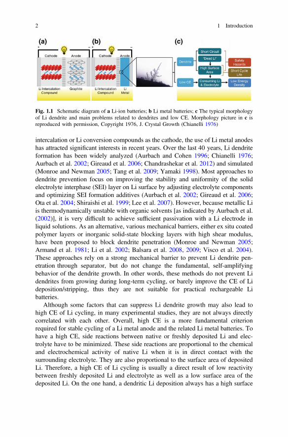
intercalation or Li conversion compounds as the cathode, the use of Li metal anodeshas attracted significant interests in recent years. Over the last 40 years, Li dendriteformation has been widely analyzed (Aurbach and Cohen 1996; Chianelli 1976;Aurbach et al. 2002; Gireaud et al. 2006; Chandrashekar et al. 2012) and simulated(Monroe and Newman 2005; Tang et al. 2009; Yamaki 1998). Most approaches todendrite prevention focus on improving the stability and uniformity of the solidelectrolyte interphase (SEI) layer on Li surface by adjusting electrolyte componentsand optimizing SEI formation additives (Aurbach et al. 2002; Gireaud et al. 2006;Ota et al. 2004; Shiraishi et al. 1999; Lee et al. 2007). However, because metallic Liis thermodynamically unstable with organic solvents [as indicated by Aurbach et al.(2002)], it is very difficult to achieve sufficient passivation with a Li electrode inliquid solutions. As an alternative, various mechanical barriers, either ex situ coatedpolymer layers or inorganic solid-state blocking layers with high shear modulus,have been proposed to block dendrite penetration (Monroe and Newman 2005;Armand et al. 1981; Li et al. 2002; Balsara et al. 2008, 2009; Visco et al. 2004).These approaches rely on a strong mechanical barrier to prevent Li dendrite pen-etration through separator, but do not change the fundamental, self-amplifyingbehavior of the dendrite growth. In other words, these methods do not prevent Lidendrites from growing during long-term cycling, or barely improve the CE of Lideposition/stripping, thus they are not suitable for practical rechargeable Libatteries.
Although some factors that can suppress Li dendrite growth may also lead tohigh CE of Li cycling, in many experimental studies, they are not always directlycorrelated with each other. Overall, high CE is a more fundamental criterionrequired for stable cycling of a Li metal anode and the related Li metal batteries. Tohave a high CE, side reactions between native or freshly deposited Li and elec-trolyte have to be minimized. These side reactions are proportional to the chemicaland electrochemical activity of native Li when it is in direct contact with thesurrounding electrolyte. They are also proportional to the surface area of depositedLi. Therefore, a high CE of Li cycling is usually a direct result of low reactivitybetween freshly deposited Li and electrolyte as well as a low surface area of thedeposited Li. On the one hand, a dendritic Li deposition always has a high surface
Fig. 1.1 Schematic diagram of a Li-ion batteries; b Li metal batteries; c The typical morphologyof Li dendrite and main problems related to dendrites and low CE. Morphology picture in c isreproduced with permission, Copyright 1976, J. Crystal Growth (Chianelli 1976)
2 1 Introduction
area. This means that the high CE of Li deposition/stripping is always related to alow surface area Li deposition and a suppressed Li dendrite growth. A stable CEvalue during long-term cycling also means that an SEI layer formed during Lideposition is relatively stable and very minimal formation of new SEI layers occursduring each cycle. On the other hand, some electrolytes can lead to dendrite-free Lideposition, but exhibit a CE of only less than 80 % (Qian et al. 2015; Ding et al.2013). This phenomenon often is related to a highly aligned nanoarray of Listructure that has no Li extrusion but still exhibits a high surface area, and freshlydeposited Li is highly reactive with the surrounding electrolyte during the cyclingprocess. Therefore, the enhancement of CE is a more fundamental factor controllinglong-term, stable cycling of a Li metal anode.
In Chap. 2 of this book, we will first review various instruments/tools that arecritical for the characterization of Li dendrite growth/stripping processes andanalysis on the composition of the surface films formed during Li deposition, thenwe will review the general models of the dendrite growth processes. The effect ofthe SEI layer on the modeling of Li dendrite growth will also be discussed, whichhas often been neglected in the literature. In Chap. 3, various factors that affect CEof Li cycling and dendrite growth will be discussed, together with an emphasis onthe enhancement of CE. This is partially due to the fact that almost all literaturearticles report the CE and Li deposition morphology together and a separatedescription will lead to significant duplications. Chapter 4 of the book will discussthe specific application of Li metal anodes in several key rechargeable Li metalbatteries, including Li-air batteries, Li–S batteries, and Li metal batteries usingother Li intercalation and Li conversion compounds as cathodes. Finally, a per-spective on the future development and application of Li metal batteries will bediscussed in Chap. 5.
References
Armand MB, Duclot MJ, Rigaud P (1981) Polymer solid electrolytes: stability domain. Solid StateIonics 3–4:429–430. doi:http://dx.doi.org/10.1016/0167-2738(81)90126-0
Aurbach D, Cohen Y (1996) The application of atomic force microscopy for the study of Lideposition processes. J Electrochem Soc 143(11):3525–3532
Aurbach D, Zinigrad E, Cohen Y, Teller H (2002) A short review of failure mechanisms of lithiummetal and lithiated graphite anodes in liquid electrolyte solutions. Solid State Ionics 148:405–416
Balsara N, Panday A, Mullin SA (2008) Polymer electrolytes for high energy density lithiumbatteries. http://www1.eere.energy.gov/vehiclesandfuels/pdfs/merit_review_2008/exploratory_battery/merit08_balsara.pdf. Accessed 12 Jan 2016
Balsara NP, Singh M, Eitouni HB, Gomez ED (2009) High elastic modulus polymer electrolytes.US Patent Appl No 0263725 A1
Bruce PG, Freunberger SA, Hardwick LJ, Tarascon J-M (2012) Li-O2 and Li-S batteries with highenergy storage. Nat Mater 11(1):19–29
1 Introduction 3

Chandrashekar S, Trease NM, Chang HJ, Du L-S, Grey CP, Jerschow A (2012) 7Li MRI of Libatteries reveals location of microstructural lithium. Nat Mater 11(4):311–315. doi:http://www.nature.com/nmat/journal/v11/n4/abs/nmat3246.html#supplementary-information
Chianelli RR (1976) Microscopic studies of transition metal chalcogenides. J Cryst Growth 34(2):239–244
Ding F, Xu W, Graff GL, Zhang J, Sushko ML, Chen X, Shao Y, Engelhard MH, Nie Z, Xiao J,Liu X, Sushko PV, Liu J, Zhang J-G (2013) Dendrite-free lithium deposition via self-healingelectrostatic shield mechanism. J Am Chem Soc 135(11):4450–4456. doi:10.1021/ja312241y
Gireaud L, Grugeon S, Laruelle S, Yrieix B, Tarascon JM (2006) Lithium metal stripping/platingmechanisms studies: a metallurgical approach. Electrochem Commun 8(10):1639–1649.doi:10.1016/j.elecom.2006.07.037
Girishkumar G, McCloskey B, Luntz AC, Swanson S, Wilcke W (2010) Lithium—air battery:promise and challenges. J Phys Chem Lett 1(14):2193–2203
Ji XL, Lee KT, Nazar LF (2009) A highly ordered nanostructured carbon-sulphur cathode forlithium-sulphur batteries. Nat Mater 8:500–506
Lee YM, Seo JE, Lee Y-G, Lee SH, Cho KY, Park J-K (2007) Effects of triacetoxyvinylsilane asSEI layer additive on electrochemical performance of lithium metal secondary battery.Electrochem Solid-State Lett 10(9):A216–A219
Lee J-S, Kim ST, Cao R, Choi N-S, Liu M, Lee KT, Cho J (2011) Metal-air batteries with highenergy density: Li–air versus Zn–air. Adv Energy Mater 1(1):34–50
Li Y, Fedkiw PS, Khan SA (2002) Lithium/V6O13 cells using silica nanoparticle-based compositeelectrolyte. Electrochimica Acta 47(24):3853–3861. doi:http://dx.doi.org/10.1016/S0013-4686(02)00326-2
Monroe C, Newman J (2005) The impact of elastic deformation on deposition kinetics atlithium/polymer interfaces. J Electrochem Soc 152(2):A396–A404. doi:10.1149/1.1850854
Ota H, Shima K, Ue M, Yamaki J-I (2004) Effect of vinylene carbonate as additive to electrolytefor lithium metal anode. Electrochim Acta 49(4):565–572. doi:10.1016/j.electacta.2003.09.010
Qian J, Xu W, Bhattacharya P, Engelhard M, Henderson WA, Zhang Y, Zhang J-G (2015)Dendrite-free Li deposition using trace-amounts of water as an electrolyte additive. NanoEnergy 15:135–144. doi:10.1016/j.nanoen.2015.04.009
Shiraishi S, Kanamura K, Takehara Z (1999) Surface condition changes in lithium metal depositedin nonaqueous electrolyte containing HF by dissolution-deposition cycles. J Electrochem Soc146(5):1633–1639. doi:10.1149/1.1391818
Tang M, Albertus P, Newman J (2009). J Electro-chem Soc 156:A390–A399Visco SJ, Nimon E, De Jonghe LC, Katz B, Chu MY (2004) Lithium fuel cells. In: Proceedings of
the 12th international meeting on lithium batteries, Nara, Japan, June 27–July 2, 2004. TheElectrochemical Society, Pennington, NJ
Whittingham MS (2012) History, evolution, and future status of energy storage. Proc IEE 100(Special Centennial Issue):1518–1534. doi:10.1109/JPROC.2012.2190170
Xu W, Wang J, Ding F, Chen X, Nasybulin E, Zhang Y, Zhang J-G (2014) Lithium metal anodesfor rechargeable batteries. Energy Environ Sci 7(2):513–537. doi:10.1039/c3ee40795k
Yamaki J-I (1998) J Power Sources 74:219–227
4 1 Introduction
Chapter 2Characterization and Modelingof Lithium Dendrite Growth
Dendrites are a common occurrence when electrodepositing metals. Although theterm “dendrite” is prevalent throughout the scientific literature when referencing Lideposition, such structures are atypical (i.e., in general, the plated Li morphologydoes not consist of regular branched, tree-like structures). Instead, Li tends to platefrom solution as particles/nodules or whiskers/needles/filaments, which canaggregate into more complex constructs. Due to its ubiquitous usage for Li elec-trochemistry, however, the term “dendrite” will be used throughout the text in thisbook to refer to the latter structures. It is also notable that the literature thataddresses the theory of Li electrodeposition has focused largely on the numerousdeterminant factors that influence classical dendritic metal plating, but the evolutionof the plated Li structural characteristics is in actuality dictated to a great extent bythe concurrent reactions between the reactive Li and electrolyte components (i.e.,SEI formation).
2.1 Characterization of Lithium Dendrite Growth
As discussed in Chap. 1, the Li dendrite growth during the Li deposition process isa critical issue for the battery safety. Extensive efforts have been made to charac-terize and analyze the formation and growth processes of Li dendrites in order toreveal the mechanisms of dendrite formation and growth processes and then find theapproaches to suppress or prevent the dendrite formation. In the last four decades,many different characterization methods have been used to study Li electrodes andthe dendrite formation, including scanning electron microscopy (SEM) (Aurbachet al. 1998; Dollé et al. 2002), optical microscopy (Howlett et al. 2003; Nishikawaet al. 2010; Arakawa et al. 1993), atomic force microscopy (AFM) (Aurbach andCohen 1997), transmission electron microscopy (TEM) (Liu et al. 2011; Ghassemiet al. 2011), nuclear magnetic resonance (NMR) (Chang et al. 2015), Fouriertransform infrared spectroscopy (FTIR) (Morigaki 2002; Aurbach et al. 1987, 1995,
© Springer International Publishing Switzerland 2017J.-G. Zhang et al., Lithium Metal Anodes and RechargeableLithium Metal Batteries, Springer Series in Materials Science 249,DOI 10.1007/978-3-319-44054-5_2
5
1997; Kanamura et al. 1997), and x-ray photoelectron spectroscopy (XPS) (Otaet al. 2004a; Aurbach et al. 1993; Kanamura et al. 1995b). Both morphology andchemical composition of the deposited Li metal films have been extensivelyinvestigated. The main approaches used in the characterization of electrochemicallydeposited Li metal films are briefly introduced in this chapter.
2.1.1 Characterization of Surface Morphologies
2.1.1.1 SEM
Among various observation methods, SEM is the most common and useful tech-nique to examine Li electrode surface morphologies. Morphology study focuses onvariation of the Li surface and formation of Li dendrites. Since the 1970s, thismethod has been used to study Li film growth (Dey 1976) both ex situ and in situduring dendrite growing/stripping processes (Ding et al. 2013, 2014; Zhamu et al.2012; Ryou et al. 2012; Stark et al. 2011; Aurbach et al. 1989, 1990a, 1994b;Besenhard et al. 1987; Kanamura et al. 1995a; Yamaki et al. 1998; Shiraishi et al.1999; Ota et al. 2004a; Gireaud et al. 2006; López et al. 2009; Nazri and Muller1985b; Yoshimatsu et al. 1988; Choi et al. 2011; Lee et al. 2006; Yoon et al. 2008;Li et al. 2014a; Bieker et al. 2015). With its high resolution images, SEM is apowerful technique to analyze the surface change of Li metal during the depositionand stripping cycles. The effects of solvents (Aurbach et al. 1990a, b; Besenhardet al. 1987; Ota et al. 2004a; Bieker et al. 2015; Naoi et al. 1999), salts (Aurbachet al. 1994; Kanamura et al. 1995a; Yang et al. 2008), additives, (Shiraishi et al.1999; Fujieda et al. 1994; Osaka et al. 1997b; Ota et al. 2004b; Lee et al. 2007), andother treatments (Stark et al. 2011; Thompson et al. 2011; Stark et al. 2013) havebeen directly discovered using SEM images. With the help of SEM observations,the correlation between the surface chemistry and morphology of Li electrodes wasbuilt (Aurbach et al. 1994), and the morphological transitions on Li metal anodesduring cycling were examined (López et al. 2009). In the ex situ SEM studies, theLi samples have been transferred into the SEM instrument chamber in an inertatmosphere to avoid reaction of Li metal with ambient air as described by Kohl andcoworkers (Stark et al. 2011). In the in situ SEM observation of Li dendrite for-mation, Orsini et al. (1998, 1999) first reported using in situ SEM to observe thecross section of plastic rechargeable Li batteries using solid polymer electrolytes.They observed the accumulation of mossy Li and growth of dendritic Li at theLi/polymer electrolyte (Fig. 2.1), which was the origin of rapid interface deterio-ration and capacity fading.
Neudecker et al. (2000) used in situ SEM to observe variation in the behavior ofthe anode current collector and the overlayer during Li deposition and stripping inan in situ built solid-sate thin-film battery. The cross-sectional SEM image of thebattery is shown in Fig. 2.2a. During the initial charge of the battery at 4.2 V, Liwas plated between the anode current collector (i.e., Cu) and the solid-state
6 2 Characterization and Modeling of Lithium Dendrite Growth
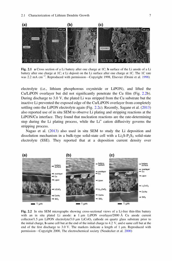
electrolyte (i.e., lithium phosphorous oxynitride or LiPON), and lifted theCu/LiPON overlayer but did not significantly penetrate the Cu film (Fig. 2.2b).During discharge to 3.0 V, the plated Li was stripped from the Cu substrate but theinactive Li prevented the exposed edge of the Cu/LiPON overlayer from completelysettling onto the LiPON electrolyte again (Fig. 2.2c). Recently, Sagane et al. (2013)also reported use of in situ SEM to observe Li plating and stripping reactions at theLiPON/Cu interface. They found that nucleation reactions are the rate-determiningstep during the Li plating process, while the Li+ cation diffusivity governs thestripping process.
Nagao et al. (2013) also used in situ SEM to study the Li deposition anddissolution mechanism in a bulk-type solid-state cell with a Li2S-P2S5 solid-stateelectrolyte (SSE). They reported that at a deposition current density over
Fig. 2.1 a Cross section of a Li battery after one charge at 1C; b surface of the Li anode of a Libattery after one charge at 1C; c Li deposit on the Li surface after one charge at 1C. The 1C ratewas 2.2 mA cm−2. Reproduced with permission—Copyright 1998, Elsevier (Orsini et al. 1998)
Fig. 2.2 In situ SEM micrographs showing cross-sectional views of a Li-free thin-film batterywith an in situ plated Li anode: a 1 lm LiPON overlayer/2000 Å Cu anode currentcollector/1.5 lm LiPON electrolyte/3.0 lm LiCoO2 cathode on quartz glass substrate prior tothe initial charge, b same cell but at the end of the initial charge to 4.2 V, and c same cell but at theend of the first discharge to 3.0 V. The markers indicate a length of 1 lm. Reproduced withpermission—Copyright 2000, The electrochemical society (Neudecker et al. 2000)
2.1 Characterization of Lithium Dendrite Growth 7
1 mA cm−2, the local Li deposition triggered large cracks, resulting in a decrease inthe reversibility of Li deposition and dissolution. On the other hand, at a low currentdensity of 0.01 mA cm−2, Li deposition was homogeneous thus greatly reducingthe occurrence of unfavorable cracks, which enables reversible deposition anddissolution. These results suggest that homogeneous Li deposition on the surface ofthe SSE and suppression of the growth of Li metal along the grain boundaries insidethe SSE are the keys to achieve the repetitive Li deposition and stripping withoutdeterioration of the SSE. Clearly, SEM (either ex situ or in situ) is a very usefultechnique to investigate morphology variations of Li electrodes during depositionand stripping in open cells (Li et al. 2014a). However, because of the ultrahighvacuum condition in SEM tests, most in situ SEM investigations of Lideposition/stripping processes are performed on batteries using solid polymer orinorganic SSE. It is still difficult to conduct an in situ observation of Li formationand growth in conventional liquid electrolytes, which is more relevant to most ofpractical applications.
2.1.1.2 Optical Microscopy
Optical microscopy is another way to observe the Li dendrites and it has beenwidely used as an in situ method to observe and record the Li dendritegrowing/stripping processes under working conditions close to those of practicalapplications (Osaka et al. 1997a). Although the resolution of optical microscopy isnot as high as that of SEM, it still could easily and instantaneously distinguish thesurface change and dendrite formation. It is an intuitional observation on Li elec-trodes and very helpful to understand a continuous dendrite growing/strippingprocess. With digital recording devices, the dendrite formation process can berecorded as a video. Therefore, the optical microscopy technique has been widelyused to analyze Li electrodes in situ. However, a special optical cell is needed forin situ optical study of Li dendritic growth. Usually, such a cell is homemade asdescribed by Brissot et al. (1998). The optical cell could work as an airtight elec-trochemical cell, and the Li electrode surface could be observed by opticalmicroscopy. In the in situ observation, optical microscopy is more often used tostudy the cross section of a Li electrode to observe the dendrite growth perpen-dicular to the surface of the Li electrode (Stark et al. 2013; Brissot et al. 1998,1999b; Sano et al. 2011; Howlett et al. 2003; Hernandez-Maya et al. 2015).Figure 2.3 shows typical dendrites formed at different current densities duringin situ optical microscopy study. At low current density (0.2 mA cm−2), needle-likeand particle-like dendrites are observed, while at higher current densities(� 0.7 mA cm−2), dendrites have a tree-like or bush-like shape. Figure 2.4 showsthe evolution of Li dendrites observed in the inter-electrode space while the cell isbeing polarized (at 0.05 mA cm−2). The needle-like dendrite grows on the negativeelectrode and finally contacts the positive electrode, causing short circuit of the cell.
8 2 Characterization and Modeling of Lithium Dendrite Growth

2.1.1.3 AFM
AFM is another useful technique to investigate Li electrode morphology. Theresolution of AFM is much better than that of optical microscopy. At the same time,AFM can give a three-dimensional (3D) morphology image that is difficult to get
Fig. 2.3 Typical dendritesobtained with different currentdensities: a J = 0.2 mA cm−2
(needle-like dendrites),b J = 0.7 mA cm−2
(tree-like dendrites),c J = 1.3 mA cm−2 (bush-likedendrites). Reproduced withpermission—Copyright 1998,Elsevier (Brissot et al. 1998)
Fig. 2.4 Time variation ofthe dendrites observed in theinter-electrode space whilepolarizing the cell withJ = 0.05 mA cm−2. Dendritesare seen to be needle-like. Itshows that the dendrite growson negative electrode withtime and finally contacts thepositive electrode, causingshort circuit of the cell.Reproduced with permission—Copyright 1999, Elsevier(Brissot et al. 1999b)
2.1 Characterization of Lithium Dendrite Growth 9
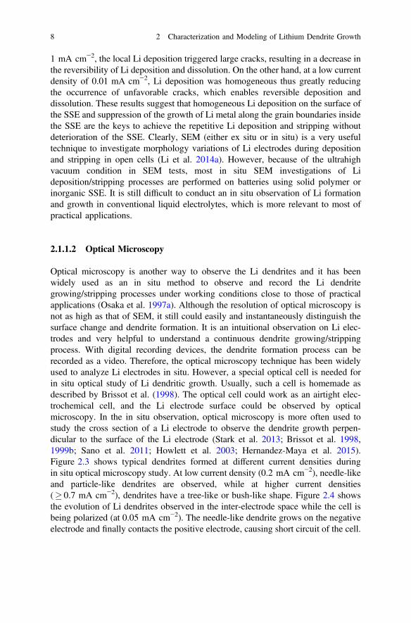
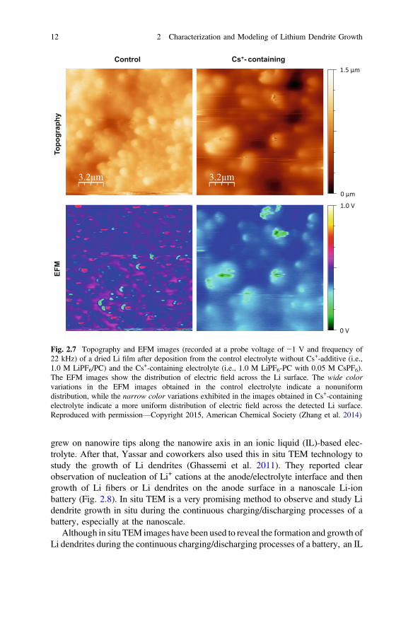
from SEM or optical microscopy. In 1996, Aurbach and Cohen first used AFM tostudy the Li deposition processes in nonaqueous electrolyte systems (Aurbach andCohen 1996). In that work, the basic electrochemical cell was modified to hold thehighly sensitive electrodes and electrolyte solution and to isolate them fromatmospheric contaminants. They found that the AFM scanning is not destructiveand does not change the morphology on the surface. After that, more work(Morigaki and Ohta 1998; Aurbach et al. 1999; Cohen et al. 2000; Morigaki 2002;Mogi et al. 2002a, b, c) using in situ AFM was conducted. With the special 3Dmorphology of AFM images, the swelling and shrinking of Li surfaces during Lideposition and stripping processes have been discovered (Morigaki 2002).Figure 2.5 shows AFM images of a Li surface film deposited in a 0.5 M LiAsF6/propylene carbonate (PC) electrolyte, where (a) a bump after Li deposition and(b) shrinkage after consecutive Li stripping are clearly seen (Morigaki 2002).Moreover, investigation by AFM has revealed that the structure of the Li surfaceconsists of grain boundaries, ridge lines, and flat areas (Morigaki and Ohta 1998),which cannot be proven by other morphology test methods including SEM andoptical microscopy. Based on these findings, the breakdown and reparation of theSEI films on Li electrodes during Li deposition/stripping cycles have been proposed(Fig. 2.6) and probed (Aurbach and Cohen 1996; Cohen et al. 2000).
Several modified AFM methods have also been used in the characterization of Lifilm deposition. Shiraishi et al. reported using in situ fluid tapping-mode AFM(TMAFM) coupled with an electrochemical quartz crystal microbalance to inves-tigate the electrochemical stripping behavior of Li metal in nonaqueous electrolytescontaining a small amount of HF (Shiraishi and Kanamura 1998), and also usingTMAFM with surface potential microscopy (SPoM) to study the surface conditionof the electrodeposited Li on a Ni substrate (Shiraishi et al. 2001). Recently, Zhanget al. (2014) used amplitude-modulated electrostatic force microscopy (AM-EFM)(a special type of AFM) to study the surfaces of deposited Li films. The Li films
Fig. 2.5 AFM images (1 � 1 lm) of a Li electrode in a 0.5 M LiAsF6/PC solution. a an imageobtained after Li deposition, 0.41 C cm−2. New Li deposits are marked by a circle. b an image ofthe same area after consecutive Li dissolution (0.41 C cm−2). The same area marked in a is alsocircled here. Reproduced with permission—Copyright 2000, American Chemical Society (Cohenet al. 2000)
10 2 Characterization and Modeling of Lithium Dendrite Growth

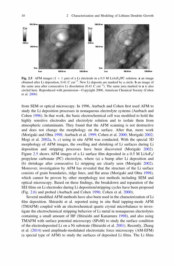
were electrodeposited for 15 h on Cu foils in electrolytes of 1 M LiPF6-PC withoutand with 0.05 M CsPF6 additive. Li dendrites were formed in the control electrolyte(i.e., without Cs+ additive) and a smooth Li film was obtained in the Cs+ containingelectrolyte. As shown in Fig. 2.7, the EFM images recorded at a probe voltage of−1 V for the Li film formed in the control electrolyte exhibit wide color variationsor a strong contrast, which indicates a large fluctuation and nonuniform distributionof electric field across the detected Li surface. In comparison, the EFM image forthe Li film formed in the Cs+-containing electrolyte shows narrow color variationsor relatively small contrast, indicating a uniform distribution of the electric fieldacross the Li surface and is consistent with a smooth Li film.
2.1.1.4 TEM
Due to the success of the application of optical microscopy in the observation ofmorphologies of deposited Li films in microscale, another electron microscopy, i.e.,in situ TEM, was recently used to observe in real time the formation of Li fibers orLi dendrite growth at nanoscale (Liu et al. 2011; Ghassemi et al. 2011). Huang andcoworkers first reported the direct observation of Li fiber growth on differentnanowire anodes (such as silicon or tin oxide) during in situ charging of nanoscaleLi-ion batteries inside a TEM (Huang et al. 2010). Li fibers of up to 35 µm long
Fig. 2.6 A description of the morphology and failure mechanisms of Li electrodes during Lideposition and dissolution illustrating selected phenomena: the beginning of dendrite formation(top) and nonuniform Li dissolution accompanied by breakdown and reparation of the surfacefilms (bottom). Reproduced with permission—Copyright 2000, American Chemical Society(Cohen et al. 2000)
2.1 Characterization of Lithium Dendrite Growth 11
grew on nanowire tips along the nanowire axis in an ionic liquid (IL)-based elec-trolyte. After that, Yassar and coworkers also used this in situ TEM technology tostudy the growth of Li dendrites (Ghassemi et al. 2011). They reported clearobservation of nucleation of Li+ cations at the anode/electrolyte interface and thengrowth of Li fibers or Li dendrites on the anode surface in a nanoscale Li-ionbattery (Fig. 2.8). In situ TEM is a very promising method to observe and study Lidendrite growth in situ during the continuous charging/discharging processes of abattery, especially at the nanoscale.
Although in situ TEM images have been used to reveal the formation and growth ofLi dendrites during the continuous charging/discharging processes of a battery, an IL
1.5 μm
0 μm
1.0 V
0 V
Topo
grap
hyEF
MControl Cs+- containing
Fig. 2.7 Topography and EFM images (recorded at a probe voltage of −1 V and frequency of22 kHz) of a dried Li film after deposition from the control electrolyte without Cs+-additive (i.e.,1.0 M LiPF6/PC) and the Cs+-containing electrolyte (i.e., 1.0 M LiPF6-PC with 0.05 M CsPF6).The EFM images show the distribution of electric field across the Li surface. The wide colorvariations in the EFM images obtained in the control electrolyte indicate a nonuniformdistribution, while the narrow color variations exhibited in the images obtained in Cs+-containingelectrolyte indicate a more uniform distribution of electric field across the detected Li surface.Reproduced with permission—Copyright 2015, American Chemical Society (Zhang et al. 2014)
12 2 Characterization and Modeling of Lithium Dendrite Growth

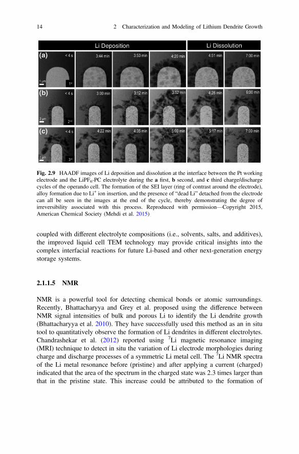
electrolyte or an SSE has to be used in most in situ TEM studies because the highvapor pressure of a practical liquid electrolyte is not compatible with the high vacuumrequired by a conventional TEM system. It is well known that an SEI layer formed onthe surface of a Li film or dendrite is critical for Li deposition/stripping. However, theSEI formed in IL or SSE is greatly different from those formed in the conventionalelectrolytes used in Li metal batteries. Therefore, the interaction between Li dendritesand a practical liquid electrolyte still cannot be observed in these in situ TEM studies.Very recently, with the development of liquid cells for in situ TEM techniques, a trueoperando TEM investigation on Li dendrite growth has been performed in electro-chemical cells with conventional liquid electrolytes for Li-ion batteries (Gu et al.2013;Mehdi et al. 2014, 2015; Sacci et al. 2014). Sacci et al. (2014) reported the directvisualization of an initial dendritic SEI formation prior to Li deposition, and thisdendritic morphology remained on the surface after Li dissolution during the in situelectrochemical TEM study, which used 1.2 M LiPF6 in ethylene carbonate (EC)/dimethyl carbonate (DMC) (3:7 by wt) as electrolyte. Mehdi et al. (2015) used in situelectrochemical scanning TEM (STEM) to study the initial stages of SEI formationand Li dendrite evolution at the anode/electrolyte interface during Lideposition/stripping processes in 1 M LiPF6/PC electrolyte. The high-angle annulardark field (HAADF) STEM images of the anode/electrolyte interface during the firstthree charge-discharge cycles of this operando Li battery are shown in Fig. 2.9. Thedeposition and stripping of Li is clearly observed. Some electrochemically inactive or“dead” Li residues around the electrode after Li stripping for all the three cycles arepresent, which are no longer attached to the Pt electrode.
Presently, the liquid cell TEM gives relatively lower resolution images than theopen cell (i.e., vacuum conditioned) TEM does due to the limitation of cellthickness required to hold liquid electrolyte. Therefore, future improvement isrequired on the liquid cell fabrication (including electrodes with different alloyingperformance and control of the thickness) along with use of faster imaging methods.Such improvements should enable the clear observations of the initial stages ofdifferent mechanisms to be quantified on the nanometer to atomic scale. When
Fig. 2.8 a Black arrows indicate an individual silicon nanorod surrounded by ionic liquid.b Arrows indicate the formation of Li islands on the nanorod. c Represents the growth of Li fibers.d The formation of kinks and growth of Li fibers are marked by black arrows. Reproduced withpermission—Copyright 2011, American Institute of Physics (Ghassemi et al. 2011)
2.1 Characterization of Lithium Dendrite Growth 13
coupled with different electrolyte compositions (i.e., solvents, salts, and additives),the improved liquid cell TEM technology may provide critical insights into thecomplex interfacial reactions for future Li-based and other next-generation energystorage systems.
2.1.1.5 NMR
NMR is a powerful tool for detecting chemical bonds or atomic surroundings.Recently, Bhattacharyya and Grey et al. proposed using the difference betweenNMR signal intensities of bulk and porous Li to identify the Li dendrite growth(Bhattacharyya et al. 2010). They have successfully used this method as an in situtool to quantitatively observe the formation of Li dendrites in different electrolytes.Chandrashekar et al. (2012) reported using 7Li magnetic resonance imaging(MRI) technique to detect in situ the variation of Li electrode morphologies duringcharge and discharge processes of a symmetric Li metal cell. The 7Li NMR spectraof the Li metal resonance before (pristine) and after applying a current (charged)indicated that the area of the spectrum in the charged state was 2.3 times larger thanthat in the pristine state. This increase could be attributed to the formation of
Fig. 2.9 HAADF images of Li deposition and dissolution at the interface between the Pt workingelectrode and the LiPF6-PC electrolyte during the a first, b second, and c third charge/dischargecycles of the operando cell. The formation of the SEI layer (ring of contrast around the electrode),alloy formation due to Li+ ion insertion, and the presence of “dead Li” detached from the electrodecan all be seen in the images at the end of the cycle, thereby demonstrating the degree ofirreversibility associated with this process. Reproduced with permission—Copyright 2015,American Chemical Society (Mehdi et al. 2015)
14 2 Characterization and Modeling of Lithium Dendrite Growth

dendritic, mossy, and other microstructural metallic Li during charging. Thetwo-dimensional 7Li MRI images before and after the cell charging are depicted inFigs. 2.10a, b, where the cumulative signals were projected along the z directionwhich is perpendicular to the substrate. The MRI image of the charged batteryrevealed the negative electrode had a significant increase in signal of almost double,while the positive electrode showed a decrease in signal of about 23 % aftercharging. It indicated the location and change of microstructural Li morphology,which is consistent with findings from SEM images (Figs. 2.10c, d). Recently, Araiet al. (2015) used in situ solid-state 7Li NMR to observe Li metal deposition duringovercharge in Li-ion batteries. Hu et al. also used in situ NMR and computationalmodeling to investigate the role of Cs+ additive (Hu et al. 2016). These worksindicate that NMR not only can detect the morphology variation during the Li metaldeposition process, but also can reveal the possible composition of SEI layersformed on the surfaces of Li films during the electrode plating process. By com-bining NMR and other characterization techniques, a more comprehensive under-standing of the electrode plated Li films can be obtained.
Fig. 2.10 7Li 2D MRI x-y images (frequency encoding in x and phase encoding in y) in the statesof pristine (a) and after charging (b), and the related SEM images of Li anode in pristine (c) andcharged (d) states. Reproduced with permission—Copyright 2012, Macmillan Publishers(Chandrashekar et al. 2012)
2.1 Characterization of Lithium Dendrite Growth 15

2.1.2 Characterization Methods for Surface Chemistry
2.1.2.1 FTIR
The characterization methods discussed in the previous sections mainly provideinformation on the morphology variations of Li depositions. Several other methodshave been used to analyze the chemical compositions of the surface films formed onthe surface of deposited Li. The chemical composition of the Li surface film isstrongly related to the electrolyte components. In turn, the SEI film formed on thesurface of a Li deposition strongly affects the Li morphology and cycling perfor-mance of a Li metal battery (Aurbach et al. 1994). In this aspect, FTIR and XPS arewidely used in this field to analyze the Li surface chemistry; FTIR is more suitablefor detecting the organic components, while XPS gives more information about theinorganic components.
Since the 1980s, FTIR has been widely used to analyze the Li surface as anondestructive method (Morigaki 2002; Aurbach et al. 1987, 1995, 1997;Kanamura et al. 1997). In the early years, FTIR was used as an ex situ method(Aurbach et al. 1987), but it was later developed as an in situ technique to analyzeLi films during electrochemical processes (Morigaki 2002; Kanamura et al. 1997).FTIR has been used to investigate the influences of electrolyte solvents, salts,additives, and other contaminants on the Li surface. From the locations andstrengths of the peaks in FTIR spectra, different chemical bonds or components onthe Li electrode surface could be identified. An example is shown in Fig. 2.11which shows FTIR spectra of Li electrodes prepared and stored for three days inEC-DMC solutions of 1 M LiAsF6, LiPF6, or LiBF4 as indicated. A spectrum of aLi electrode prepared and stored in DMC containing 0.1 M CH3OH is also pre-sented for comparison (Aurbach et al. 1997).
2.1.2.2 XPS
It should be noted that although the FTIR technique is very useful to identify thesurface components, it is limited in that it detects only the IR-active species and itcannot give the relative importance of each surface component and compositionthat affect the Li deposition morphology and battery performance. Therefore, othersurface characterization methods and technologies besides FTIR are needed to getmore detailed surface chemistry data on Li anodes. As mentioned above, XPS isanother very useful tool to analyze the surface chemistry of Li electrodes; in par-ticular, it gives more information about the elemental or inorganic components—data that FTIR cannot detect. Normally, as indicated from XPS and FTIR data byAurbach et al. (1987), the major species in a Li surface film include Li2O, LiOH,LiF, Li2CO3, lithium alkylcarbonate (RCOOLi), and hydrocarbon. Recently,
16 2 Characterization and Modeling of Lithium Dendrite Growth

Wenzel et al. (2015) used the in situ XPS technique to study the stability of an SSEin contact with Li metal. The key concept was to use the internal Ar ion sputter gunin a standard lab-scale photoelectron spectrometer to deposit thin metal films (e.g.,Li) on the sample surface and to study the reactions between metal and SSE byphotoelectron spectroscopy directly after deposition (Fig. 2.12). This approachcould give information on interfacial reactions and the interfacial kinetics, espe-cially for the interface between the alkali metal and solid electrolyte in solid-statebatteries.
With XPS analysis, the effects of different electrolyte solvents (Ota et al. 2004a;Aurbach et al. 1993; Kanamura et al. 1995b), lithium salts (Kanamura et al. 1995a;Fujieda et al. 1994), and additives (Shiraishi et al. 1999; Odziemkowski et al. 1992)on the Li surface chemistry have been investigated. Based on these data, especiallywith the vacuum etching technology of the XPS technique, not only the compo-nents but also the structural composition evolution of the SEI film can be revealedby XPS analysis (Ding et al. 2014; Kanamura et al. 1995a; Shiraishi et al. 1999;Zhang et al. 2014; Aurbach et al. 1993; Qian et al. 2015a, b).
Fig. 2.11 FTIR spectra of Li electrodes prepared and stored for three days in EC-DMC solutionsof 1 M LiAsF6, LiPF6, or LiBF4 as indicated. A spectrum of a Li electrode prepared and stored inDMC containing 0.1 M CH3OH is also presented for comparison. Reproduced with permission—Copyright 1997, Elsevier (Aurbach et al. 1997)
2.1 Characterization of Lithium Dendrite Growth 17

2.1.3 Other Characterization Techniques
In addition to the methods discussed in the above sections, several other methods,including Raman spectroscopy (Raman) (Kominato et al. 1997), Auger electronspectroscopy (AES) (Ota et al. 2004a; Morigaki and Ohta 1998; Aurbach et al.1993), and NMR (Kominato et al. 1997) have been used to analyze the surfacechemistry of electroplated Li films. So far, attempts to use Raman spectroscopy toidentify the surface films on the Li metal/electrolyte interphase have not been verysuccessful. Only a few papers reported the Raman studies (Howlett et al. 2003; Reyet al. 1998a, b; Naudin et al. 2003). For example, Irish et al. used a Ramanmicroprobe to study both in situ and ex situ the surface films formed on Li metal incontact with electrolytes of LiAsF6/tetrahydrofuran (THF) and LiAsF6/2MeTHF(Odziemkowski et al. 1992). The reaction products detected were mainly polyte-trahydrofuran, some arsenolite (As2O3), and arsenious oxyfluorides F2As-O-AsF2.Raman technology might be expected to yield results similar to those of FTIRspectroscopy, but this technology is more complicated to use than FTIR(Odziemkowski et al. 1992). In addition, as indicated by Naudin et al. (2003), localheating of the samples under laser irradiation is unavoidable in Raman tests. Thecarbonate species on Li surface could be transformed into lithium acetylides ofLi2C2 type, which gives a vibration peak of C�C at about 1845 cm−1, thus giving a
Fig. 2.12 The basic concept and setup of the in situ XPS technique. An argon ion beam is used tosputter lithium, gold or aluminum metal on the sample surface (a). In (b) the geometry isschematically shown. After deposition, the reaction products formed at the interface (d) areinvestigated using photoelectron spectroscopy, as shown in (c). Reproduced with permission—Copyright 2015, Elsevier (Wenzel et al. 2015)
18 2 Characterization and Modeling of Lithium Dendrite Growth

faulty result to the interpretation. Therefore, the destructive effect of Raman laserbeam on Li surfaces limits its use in the analysis of Li surface films.
Aurbach et al. (1993) used AES to measure the Li surface after the Li wasimmersed in an electrolyte of 0.2 M LiAsF6/1,2-dimethoxyethane (DME) for15 min followed by pure DME rinsing. They found that the AES spectra weresimilar to those seen with XPS. Carbon and oxygen were detected at the Li surface.With sputtering, the intensity of the carbon Auger peak decreased while the oxygenpeak increased when compared to their initial peaks. It was suggested that thesurface films of Li treated in DME consisted of two layers, the upper layer being analkoxide film (probably LiOCH3) and the layer close to Li being a mixture of Li2Oand LiOH. Kominato et al. (1997) also used AES to detect the surface compoundsof Li after it was immersed in three electrolytes of EC/DMC with LiPF6, LiClO4, orLiTFSI. Except for LiF found in the Li surface film from the LiPF6-based elec-trolyte, all major components in the three Li surfaces were Li–O componentsindicating LiOH, Li2O, or other lithium oxide compounds. Morigaki and Ohta usedscanning AES to analyze the Li surface in 1 M LiClO4/PC solution also used AESto detect the surface compounds of Li after it was immersed in three electrolytes ofEC/DMC with LiPF6, LiClO4, or LiTFSI. Except for LiF found in the Li surfacefilm from the LiPF6-based electrolyte, all major components in the three Li surfaceswere Li–O components indicating LiOH, Li2O, or other lithium oxide compounds.Morigaki and Ohta (1998) used scanning AES to analyze the Li surface in 1 MLiClO4/PC solution. Li2CO3, Li2O, and LiOH were localized on the ridge lines andthe grain boundaries of the Li surface. AES technology can provide some usefulinformation about the Li surface components, but it is very close to that obtainedfrom XPS analysis. In addition, the AES equipment is more difficult to access thanXPS equipment, so AES analysis has been used less frequently in Li metalinvestigations.
NMR has also been used to study the Li surface chemistry. Ota et al. (2004a, c)used NMR technology (1H, 13C and 2D spectra) to analyze the surface componentsof deposited Li by dissolving the surface film in anhydrous dimethyl sulfoxide(DMSO)-d6 and then recording the NMR spectra of the organic species in theDMSO-d6 solution. They found that the organic surface layer on Li metal includedlithium ethoxide, lithium ethylene dicarbonate, PEO, and lithium ethylene con-taining an oxyethylene unit. This is an indirect method to analyze the Li surfacefocusing on the dissolvable organic species. The obvious limitation of this tech-nique is the inability to analyze the insoluble inorganic compounds formed on Lisurfaces.
Nazri and Muller used secondary ion mass spectrometry (SIMS) to study thesurface layer formed on electrochemically deposited Li on copper in a 1 M LiClO4-PC electrolyte (Nazri and Muller 1985b). The obtained SIMS spectrum was com-plex and was difficult to interpret. Basically, the low mass range showed thefragments of PC, the salt, and water, while the high mass range indicated thepresence of a polymeric material based on PC, a partially chlorinated hydrocarbonpolymer, and their lithium adducts. The authors also applied the in situ x-raydiffraction (XRD) technique to the analysis of the formed Li surface films (Nazri
2.1 Characterization of Lithium Dendrite Growth 19

and Muller 1985a, b, c). The presence of Li2CO3, Li2O, and polymer compoundswas also detected.
Temperature-programmed decomposition mass spectroscopy (TPD-MS) and gaschromatography–mass spectrometry (GC-MS) technology were also used by sev-eral groups to analyze the surface components of Li electrodes (Matsuda et al.1995). Kominato et al. (Morigaki and Ohta 1998; Kominato et al. 1997) reportedthat the gases generated from Li films pretreated in EC-dimethyl carbonate(DMC) based electrolytes were mainly CH4, H2O, CO, CH3OH, CO2, and ethyleneoxide. N2 was also detected if LiTFSI was used as the electrolyte salt. The GC-MSdetected the same gas components. This indicated that the detected gases weregenerated from the organic Li compounds that were the reaction products of Li andsolvents (EC and DMC) and included lithium ethylene dicarbonate and lithiummethylcarbonate. Ota et al. (2004a, c) also used GC-MS to investigate the Lisurface compounds generated in EC/THF electrolytes. C2H4, CO2, and C2H6 weredetected and were mainly from the reductive components of EC. During TPD-MSand GC-MS measurements, the Li electrodes with the detected surface films need tobe heated to give off the gases to be tested. The data from these MS measurementscould provide more information on the Li surface film chemistry and support theresults of other film measurements, such as FTIR and XPS.
Ota et al. (2004a, c) used ion chromatography (IC) to quantitatively analyze theLi surface films. The Li films were first dissolved in high-purity water and thentested by an IC instrument. By analyzing the contents of F−, CO3
2−, and Li+ ions,quantitative information about the Li surface films could be obtained. They foundthat the Li surface film in EC-based electrolytes consisted mainly of lithium alkylcarbonate, and LiF content in the films formed in an electrolyte containing lithiumimide salt was lower than those formed in the electrolytes containing LiPF6 salt.
The in situ scanning vibrating electrode technique has also been used to map thesurface electric field of Li electrodes (Matsuda et al. 1995; Ishikawa et al. 1997).The surface electric field on a Li electrode is based on its morphology and com-position uniformity. So this technology reflects not only the surface morphology,but also the chemical composition uniformity of the Li surface. However, becausethe scanning step of this technology is not small enough, the definition obtainedusing this technology is not satisfactory.
In a recent effort, Harry et al. (2014, 2015) used synchrotron hard x-raymicrotomography to investigate the failure caused by dendrite growth inhigh-energy density, rechargeable batteries with Li metal anodes. When a sym-metric Li|polymer electrolyte|Li cell was cycled at 90 °C, they found that the bulkof the dendritic structure lay within the electrode, underneath the polymer/electrodeinterface, during the early stage of dendrite development. Furthermore, theyobserved crystalline impurities, present in the uncycled Li anodes, at the base of thesubsurface dendritic structures. The portion of the dendrite protruding into theelectrolyte increases on cycling until it spans the electrolyte thickness, causing ashort circuit. Contrary to conventional wisdom, it seems that preventing dendriteformation in polymer electrolytes depends on inhibiting the formation of subsurfacestructures in the Li electrode. These results demonstrate that x-ray
20 2 Characterization and Modeling of Lithium Dendrite Growth

microtomography is another powerful tool to provide a clear failure mechanism inLi metal batteries.
In summary, characterization of morphologies and surface components ofelectroplated Li anodes is a complicated task. SEM and FTIR/XPS are the mostcommon methods used to investigate the surface morphology and chemistry,respectively, of the electrodeposited Li films. Many other methods discussed in thischapter also provide valuable information on Li films. However, no single tech-nique is enough to provide comprehensive understanding of the studied Li films,especially for the surface reaction products or SEI layer formed on a Li film.Therefore, a combination of multiple characterization and analysis methods isrequired to have a good understanding of the properties of electrodeposited Li films.
2.2 Effect of SEI Layer on Lithium Dendrite Growth
Various models proposed in the literature have provided important guidance on thenucleation and growth of metal dendrites, especially for metals that do not reactwith electrolyte in a significant way. However, Li is thermodynamically unstablewith any organic solvent and the two react instantaneously to form an SEI. This SEIlayer will continuously break down and regrow during Li deposition/strippingprocesses and is critical to the real growth pattern of reactive metals such as Li.Unfortunately, most models in the literature do not consider the impact of the SEIon the Li dendrite growth mechanisms. Recently, Cheng et al. (Cheng et al. 2015)reviewed the mechanisms of SEI formation and models of SEI structure. Thecritical factors affecting the SEI formation, such as electrolyte component, tem-perature, current density, are discussed. An extensive experimental study by Steigeret al. utilizing in situ light microscopy and ex situ SEM analysis concluded,however, that growth of the whisker/needle-like structures (often termed “den-drites”) occurs as follows (Steiger et al. 2014b, 2015; Steiger 2015):
• Li needle growth is generally initiated at either the substrate surface or fromfaceted particles of Li.
• Typically, the needles grow in length, but not in breadth.• Growth often does not actually occur at the tip, but rather behind an inactive
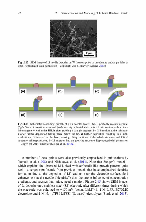
deposit located at the tip (possibly a particle of metal oxide, LiF or other SEIcomponents) (Figs. 2.13, 2.14) (Steiger et al. 2014a).
• Li+ cation transport through a thin SEI layer results in the overall needle growthwhich occurs—as just noted—at the needle tip (i.e., deposit-Li interface), at thebase (i.e., substrate-Li interface), and at defects resulting in kinks in the needles.
• Extensive shaking/twisting motions transpire during the needle growth process(Steiger et al. 2014a; Brissot et al. 1998; Nishikawa et al. 2007, 2010, 2011,2012; Nishida et al. 2013; Yamaki et al. 1998)—a characteristic that is readilyexplained by the differing growth zones (kinks and interfaces) in Steiger’smodel.
2.1 Characterization of Lithium Dendrite Growth 21
A number of these points were also previously emphasized in publications byYamaki et al. (1998) and Nishikawa et al. (2011). Note that Steiger’s model—which explains the observed Li kinked whisker/needle-like growth patterns quitewell—diverges significantly from previous models that have emphasized dendriteformation due to the depletion of Li+ cations near the electrode surface, fieldenhancement at the needle (“dendrite”) tips, the strong influence of concentrationgradients, and stresses that induce needle motion. Figure 2.15 shows SEM imagesof Li deposits on a stainless steel (SS) electrode after different times during whichthe electrode was polarized to −150 mV (versus Li/Li+) in 1 M LiPF6-EC/DMCelectrolyte and 1 M N1114TFSI-LiTFSI (IL-based) electrolytes (Stark et al. 2013).
Fig. 2.13 SEM image of Li needle deposits on W (arrows point to broadening and/or particles attips). Reproduced with permission—Copyright 2014, Elsevier (Steiger 2015)
Fig. 2.14 Schematic describing growth of a Li needle: (green) SEI—probably mainly organic;(light blue) Li insertion areas and (red) inert tip. a Initial state before Li deposition with an inertinhomogeneity within the SEI, b after growing a straight segment by Li insertion at the substrate,c after further deposition taking place below the tip, d further deposition resulting in a kink,e additional Li inserted at the base, causing tilting motions of the whole structure and f finalstructure. All steps proceed by Li insertion into the growing structure. Reproduced with permission—Copyright 2014, Elsevier (Steiger et al. 2014a)
22 2 Characterization and Modeling of Lithium Dendrite Growth

When the Li deposition rate is slow, the Li nuclei formed initially will mergetogether as shown in Fig. 2.15a. When the needles grow fast relative to thenucleation points, then tangled fibrous aggregates of the kinked needles tend toresult (Fig. 2.15b).
Very different Li deposition is sometimes observed that is referred to as non-dendritic—i.e., the Li has a particulate/nodular structure, which may be fused into
Fig. 2.15 SEM images of Li deposits on a SS electrode after the indicated plating times duringwhich the electrode was polarized to −150 mV (versus Li/Li+) in a 1 M LiPF6-EC/DMCelectrolyte and b 1 M N1114TFSI-LiTFSI (IL-based) electrolytes. Reproduced with permission—Copyright 2013, The Electrochemical Society (Stark et al. 2013)
2.2 Effect of SEI Layer on Lithium Dendrite Growth 23
aggregated lumps or instead simply clustered together. This then requires a growthmodel that diverges from the linear needle model noted above. The Li depositionmorphology is governed by Li+ cation mobility, Li0 (adatom) transport on the Lisurface, and perhaps to some extent Li0 self-diffusion within the bulk of the Li.Most of the focus in many mathematical models developed is on the former (i.e.,Li+ cation mobility within the electrolyte). Jäckle and Groß found that Li0 atomself-diffusion has relatively high barriers on the most energetically favorable sur-faces of the Li body-centered cubic (bcc) crystal and also has a lower tendency(than Mg, for example) to adopt high-coordination configurations (Jäckle and Groß2014). This reduces the driving force for surface reconstruction from needle-like tonodular shapes. Higher temperatures—with the corresponding increase in Li0
adatom mobility—would therefore be expected to favor more nodular Li structures(Aryanfar et al. 2015) and this will be shown below to indeed be the case. Anotherimportant consideration, however, is the Li+ cation transport rate through the SEI tothe Li growth surface. As noted above, the kinked needle growth may be dictatedby favorable insertion of Li0 adatoms at the tip (often below an inactive particle),the base and at defects resulting in one-dimensional growth. These may be locationswhere the resistance is lowest to Li+ cation transport through the SEI or alterna-tively locations which have the lowest interfacial energy and thus serve as a sink forthe adatoms. Transport, however, will be more favorable throughout the entire SEIlayer at higher temperature and/or for a more conductive/thinner SEI. Thus, tem-perature and electrolyte composition strongly impact the Li deposition morphology(Nishikawa et al. 2011).
It will be shown below that such growth actually begins as needles which thenthicken into nodules—that is, the one-dimensional, linear elongation which createsthe needles transitions at some point to three-dimensional growth at the needle tipsand defects or alternatively thickening of the entire needle segment(s) (Steiger et al.2014b; Steiger 2015; Arakawa et al. 1993; Nishikawa et al. 2011, 2012). A highlyaligned Li growth pattern was observed when a robust and uniform SEI layerformed on the surface of the substrate as reported recently by Qian et al. (2015a),i.e., the one-dimensional, linear elongation that creates the needles transitions atsome point to three-dimensional growth.
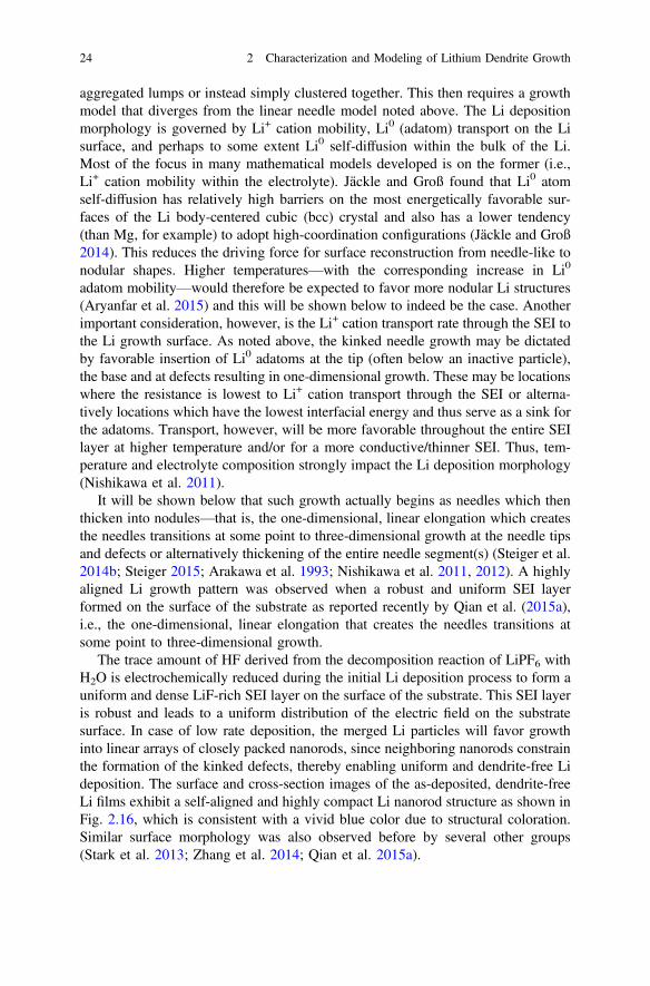
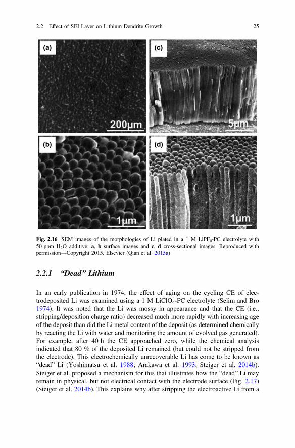
The trace amount of HF derived from the decomposition reaction of LiPF6 withH2O is electrochemically reduced during the initial Li deposition process to form auniform and dense LiF-rich SEI layer on the surface of the substrate. This SEI layeris robust and leads to a uniform distribution of the electric field on the substratesurface. In case of low rate deposition, the merged Li particles will favor growthinto linear arrays of closely packed nanorods, since neighboring nanorods constrainthe formation of the kinked defects, thereby enabling uniform and dendrite-free Lideposition. The surface and cross-section images of the as-deposited, dendrite-freeLi films exhibit a self-aligned and highly compact Li nanorod structure as shown inFig. 2.16, which is consistent with a vivid blue color due to structural coloration.Similar surface morphology was also observed before by several other groups(Stark et al. 2013; Zhang et al. 2014; Qian et al. 2015a).
24 2 Characterization and Modeling of Lithium Dendrite Growth
2.2.1 “Dead” Lithium
In an early publication in 1974, the effect of aging on the cycling CE of elec-trodeposited Li was examined using a 1 M LiClO4-PC electrolyte (Selim and Bro1974). It was noted that the Li was mossy in appearance and that the CE (i.e.,stripping/deposition charge ratio) decreased much more rapidly with increasing ageof the deposit than did the Li metal content of the deposit (as determined chemicallyby reacting the Li with water and monitoring the amount of evolved gas generated).For example, after 40 h the CE approached zero, while the chemical analysisindicated that 80 % of the deposited Li remained (but could not be stripped fromthe electrode). This electrochemically unrecoverable Li has come to be known as“dead” Li (Yoshimatsu et al. 1988; Arakawa et al. 1993; Steiger et al. 2014b).Steiger et al. proposed a mechanism for this that illustrates how the “dead” Li mayremain in physical, but not electrical contact with the electrode surface (Fig. 2.17)(Steiger et al. 2014b). This explains why after stripping the electroactive Li from a
Fig. 2.16 SEM images of the morphologies of Li plated in a 1 M LiPF6-PC electrolyte with50 ppm H2O additive: a, b surface images and c, d cross-sectional images. Reproduced withpermission—Copyright 2015, Elsevier (Qian et al. 2015a)
2.2 Effect of SEI Layer on Lithium Dendrite Growth 25

previous electrodeposition, new needle-like Li deposits often tend to grow on theelectrode surface instead of on the previous (residual) material on the electrodesurface (Brissot et al. 1998). This continues until the entire surface of the electrodeis covered by the needles and their SEI residue. Thus, the interphasial layer on thesurface of the Li may actually grow/accumulate predominantly at the workingelectrode surface rather than at the interphasial layer/electrolyte interface.
It has been reported from in situ visualization studies for both liquid and polymerelectrolytes that dendrites are often not evident during the first few cycles at highercurrent densities (for which the CE is often relatively high), but then dendrites formand grow in subsequent cycles (often resulting in a continuous decline in the CEwith continued cycling) (Dampier and Brummer 1977; Brissot et al. 1998, 1999b).This may be explained by the growth of short new needle-like deposits on theelectrode surface during the first few cycles until the electrode is covered in itsentirety by the SEI residue and “dead” Li. Then, breakaway Li dendritic structuresform while Li deposits on the electrode escape in the following cycles throughdefects in this resistive layer, culminating in the exposure of protruding kinkedneedles for which Li0 adatom addition is more facile, thus resulting in rapid growthof such dendrites.
Fig. 2.17 Schematic of proposed growth mechanism for mossy Li. The structure is alwayscovered by an SEI layer: a as-deposited, b the structure of (a) after further electrodeposition. Liatoms are inserted into the metal structure. Points have been marked with black circles to illustratethat the distances between these features generally increase with Li deposition time. The largeblack oval shape indicates the expansion of the total structure. c The structure of (a) after adissolution step. The tips of the structure still contain Li metal (“dead” Li), but are electricallyisolated from the substrate, although still being held by the former SEI shell. d Structure of (c) afteran additional electrodeposition step. The top is pushed outward by the new mossy Li growingunderneath. Reproduced with permission—Copyright 2014, Elsevier (Steiger et al. 2014b)
26 2 Characterization and Modeling of Lithium Dendrite Growth
2.2.2 Interphasial Layer and Formation of Mossy Lithium
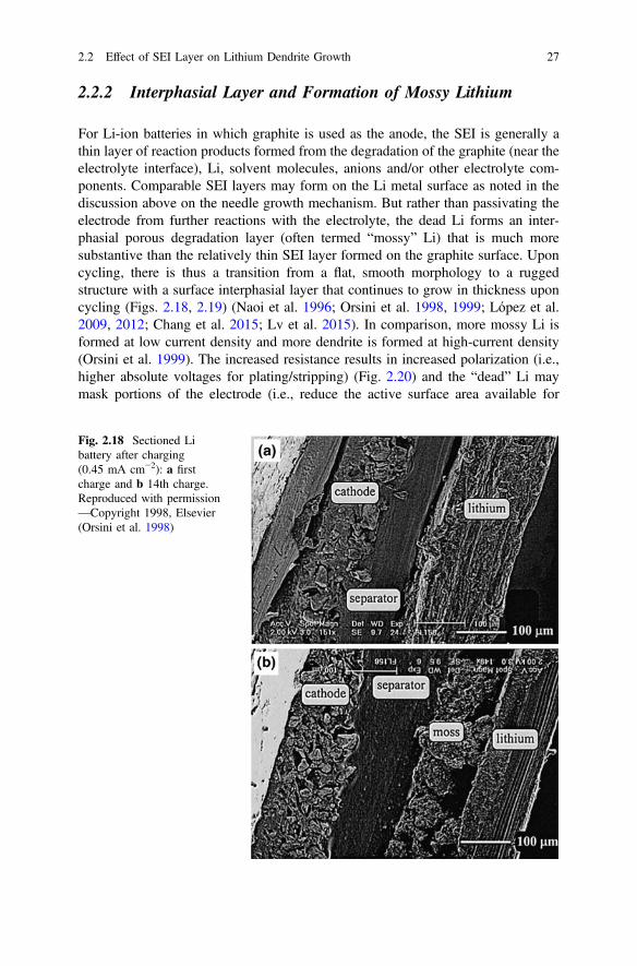
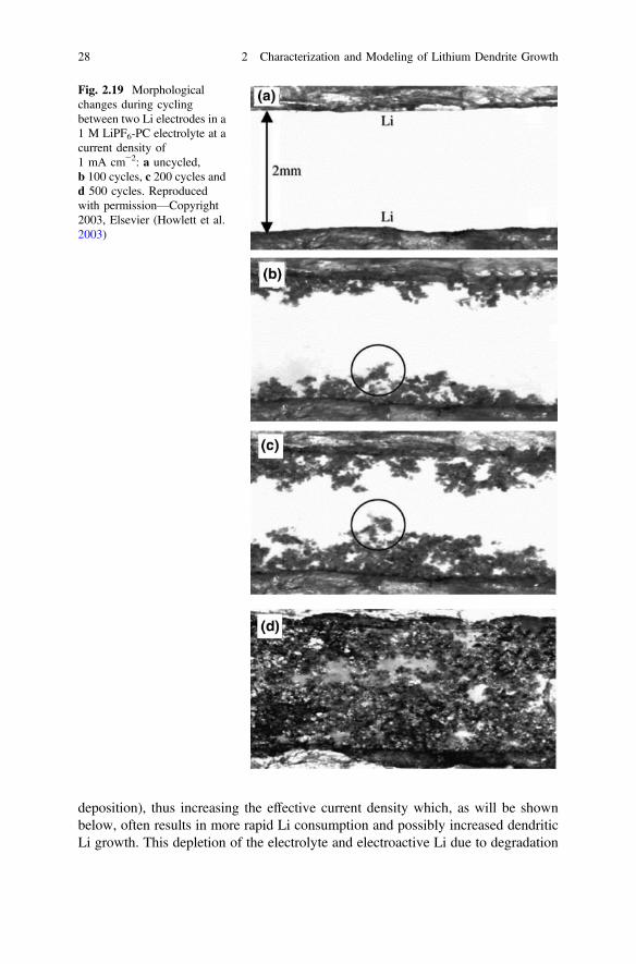
For Li-ion batteries in which graphite is used as the anode, the SEI is generally athin layer of reaction products formed from the degradation of the graphite (near theelectrolyte interface), Li, solvent molecules, anions and/or other electrolyte com-ponents. Comparable SEI layers may form on the Li metal surface as noted in thediscussion above on the needle growth mechanism. But rather than passivating theelectrode from further reactions with the electrolyte, the dead Li forms an inter-phasial porous degradation layer (often termed “mossy” Li) that is much moresubstantive than the relatively thin SEI layer formed on the graphite surface. Uponcycling, there is thus a transition from a flat, smooth morphology to a ruggedstructure with a surface interphasial layer that continues to grow in thickness uponcycling (Figs. 2.18, 2.19) (Naoi et al. 1996; Orsini et al. 1998, 1999; López et al.2009, 2012; Chang et al. 2015; Lv et al. 2015). In comparison, more mossy Li isformed at low current density and more dendrite is formed at high-current density(Orsini et al. 1999). The increased resistance results in increased polarization (i.e.,higher absolute voltages for plating/stripping) (Fig. 2.20) and the “dead” Li maymask portions of the electrode (i.e., reduce the active surface area available for
Fig. 2.18 Sectioned Libattery after charging(0.45 mA cm−2): a firstcharge and b 14th charge.Reproduced with permission—Copyright 1998, Elsevier(Orsini et al. 1998)
2.2 Effect of SEI Layer on Lithium Dendrite Growth 27
deposition), thus increasing the effective current density which, as will be shownbelow, often results in more rapid Li consumption and possibly increased dendriticLi growth. This depletion of the electrolyte and electroactive Li due to degradation
Fig. 2.19 Morphologicalchanges during cyclingbetween two Li electrodes in a1 M LiPF6-PC electrolyte at acurrent density of1 mA cm−2: a uncycled,b 100 cycles, c 200 cycles andd 500 cycles. Reproducedwith permission—Copyright2003, Elsevier (Howlett et al.2003)
28 2 Characterization and Modeling of Lithium Dendrite Growth

reactions, as well as the increased interfacial resistance from the porous interphasiallayer, has been delineated as a principal cause of cell performance degradation andfailure (Fig. 2.21) (Lv et al. 2015), although dendritic short circuiting may occur insome instances (López et al. 2009, 2012; Orsini et al. 1998, 1999; Yoshimatsu et al.1988). Thus, the large voltage spikes in Fig. 2.20 originate from the highly resistiveinterphase rather than from short circuiting (which would result in a very lowpotential between the electrodes). Importantly, for full batteries, the loss of elec-trolyte (and the corresponding significant impedance increase) may ultimately bethe key factor for the deterioration of the cell capacity rather than formation of theinterphasial layer (Aurbach et al. 2000).
2.3 Modeling of Lithium Dendrite Growth
Significant work has been done to simulate and predict the growth pattern of Lidendrite growth in the last half-century. When an electrochemical cell containing anelectrolyte with a Li salt is sufficiently polarized, Li+ cations near the negativeelectrode are reduced to Li metal and—depending upon the applied current densityand the electrolyte’s transport properties—the Li+ cation concentration decreasesresulting in anion migration toward the positive electrode until equilibrium isreached. The newly formed Li metal may deposit as a relatively compact layer or ina variety of other morphologies which are often described as dendritic. A recentreview of models for dendrite initiation/propagation described three classifications(Li et al. 2014b):
Fig. 2.20 Voltage profile for a Li||Li cell with a 1 M LiPF6-PC electrolyte cycled at a currentdensity of 1 mA cm−2. Voltage spikes are due to temporary short circuits. Reproduced withpermission—Copyright 2003, Elsevier (Howlett et al. 2003)
2.2 Effect of SEI Layer on Lithium Dendrite Growth 29
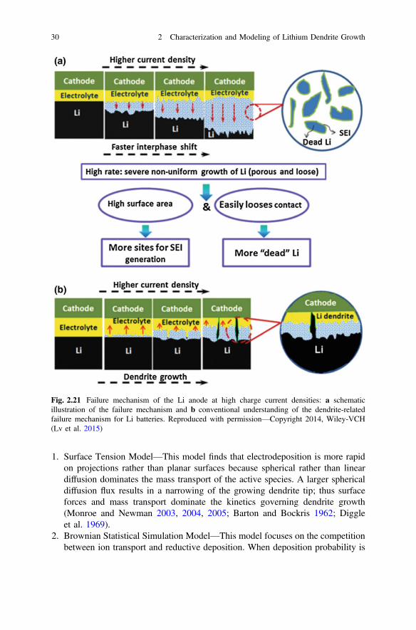
1. Surface Tension Model—This model finds that electrodeposition is more rapidon projections rather than planar surfaces because spherical rather than lineardiffusion dominates the mass transport of the active species. A larger sphericaldiffusion flux results in a narrowing of the growing dendrite tip; thus surfaceforces and mass transport dominate the kinetics governing dendrite growth(Monroe and Newman 2003, 2004, 2005; Barton and Bockris 1962; Diggleet al. 1969).
2. Brownian Statistical Simulation Model—This model focuses on the competitionbetween ion transport and reductive deposition. When deposition probability is
Fig. 2.21 Failure mechanism of the Li anode at high charge current densities: a schematicillustration of the failure mechanism and b conventional understanding of the dendrite-relatedfailure mechanism for Li batteries. Reproduced with permission—Copyright 2014, Wiley-VCH(Lv et al. 2015)
30 2 Characterization and Modeling of Lithium Dendrite Growth
low, Li+ cation transport dominates and the ions penetrate close to the substrateresulting in a dense plating morphology with a low tendency for dendrite for-mation. This is contrasted with the case of high-deposition probability (relativeto the cation transport), which increases the rate of deposition at the tip ofprojecting growth structures thus increasing the tendency for dendrite formation(Mayers et al. 2012; Voss and Tomkiewicz 1985; Magan et al. 2003).
3. Chazalviel Electromigration-Limited Model—This model for dendrite growth isoften cited: at a time s called the Sand time, the Li+ cation concentration dropsto zero at the negative electrode with high currents, causing the potential todiverge; this results in an instability at the interface from inhomogeneities in thedistribution of the surface potential, which creates a localized electric field thatleads to dendrite growth. The dendrite initiation time thus corresponds to thebuildup of the space charge and the dendrite propagation velocity is tied to thetransport of the anions (Brissot et al. 1998; Chazalviel 1990).
In addition to these, several new models have recently been proposed to describeLi plating/growth (Akolkar 2013, 2014; Chen et al. 2015; Cogswell 2015; Tanget al. 2009; Aryanfar et al. 2014). More details on a few of these important modelsof dendrite growth will be discussed in this section.
2.3.1 General Models
In the field of electrodeposition, metal “dendrites” are a common phenomenon. At agiven electrodeposition condition, many metals, such as zinc (Zn), copper (Cu),silver (Ag), and tin (Sn), were reported to exhibit ramified morphologies(Chazalviel 1990). Fractal deposits including needle-like, snowflake-like, tree-like,bush-like, moss-like, and whisker-like structures are all referred to as dendrites inthis review. Extensive work has been done on the dendrite formation mechanismduring electrodeposition of Zn and Cu. Various strategies have been unitized tosuppress dendrite growth in these processes (Sawada et al. 1986; Diggle et al.1969). The reported methods to suppress Zn dendrites include special separators,alternating current or pulsed charging, and additives in the electrolytes. The lastmethods can be further divided into three categories: electrode structural modifiers,metallic additives, and organic additives (Lan et al. 2007). Several factors such asZn concentration, complexing agents, anions, and additives may modify the textureand morphology of Zn electrodeposited coatings (Mendoza-Huízar et al. 2009).Recently, Aaboubi et al. (2011) investigated the effect of tartaric acid on Znelectrodeposition from a sulfate plating bath by electrochemical impedancespectroscopy (EIS), stationary polarization curves, XRD, and SEM imagery. Thestudy shows that it is possible to obtain homogeneous, compact, and dendrite-freeZn deposits from sulfate solutions containing tartaric acid. Miyazaki et al. (2012)
2.3 Modeling of Lithium Dendrite Growth 31

also reported suppression of dendrite formation in metallic Zn deposition using zincoxide electrodes modified with an anion-exchange ionomer (AEI). Theseimprovements are explained by selective ion permeation through the AEI films.These approaches on Zn dendrite suppression and the techniques used in theinvestigation of Zn dendrite suppression and the technics used in the investigationof Zn dendrite growth are very useful for the investigation and prevention of Lidendrite growth.
Although most electrodepositions are a one-time-only process, in a rechargeableLi metal battery, Li metal needs to be plated on or stripped from substratesrepeatedly during charge/discharge processes. As a result, Li dendrites will accu-mulate on the anode and finally lead to many serious problems (see Fig. 1.1) thathamper the practical application of rechargeable Li metal batteries. Therefore, agood understanding of the mechanism of Li dendrite formation and growth iscritical to mitigate or further eliminate Li dendrites.
Many groups have simulated the Li dendrite formation and growth process, andproposed several meaningful and fundamental models in the last forty years. Inorder to simplify the simulation conditions, most models were based on a binaryelectrolyte with a Li salt and polymer; for example, LiClO4 or LiN(SO2CF3)2(LiTFSI) in polyethylene oxide (PEO). In the open circuit condition, the electrolyteis in a steady state without an ionic concentration gradient; under polarization, theLi+ and anion will diverge and transfer to the negative and positive electrode,respectively. Li+ will obtain an electron and plate on the negative electrode. Thespeed of Li deposition or consumption of Li+ depends on the applied currentdensity. Although the depletion of Li+ can be macroscopically compensated by thesupply of Li+ from the positive electrode, the microscopic ionic distribution near thenegative electrode dramatically affects the deposit’s morphology. Therefore, a basicmodel to simulate Li dendrite starts from the calculation of the concentrationgradient in the Li symmetric cell under polarization. Brissot and Chazalviel et al.described the concentration gradient in a cell with a small inter-electrode distanceusing the following equation (Rosso et al. 2006; Brissot et al. 1999b):
@C@x
ðxÞ ¼ JlaeDðla þ lLiþ Þ
ð2:1Þ
where J is the effective electrode current density, D is the ambipolar diffusioncoefficient, e is the electronic charge, and la and lLi
+ are the anionic and Li+
mobilities. From Eq. (2.1), two different conditions for a symmetrical Li/PEO/Licell can be anticipated, with the inter-electrode distance L and initial Li salt con-centration Co:
(a) If dC/dx < 2Co/L, the ionic concentration evolves to a steady state where theconcentration gradient is constant and varies almost linearly from Ca ¼Co � DCa at the negative electrode to CLiþ ¼ Co þDCLiþ at the positiveelectrode, where
32 2 Characterization and Modeling of Lithium Dendrite Growth

�DCa � �DCLiþ � lala þ lLiþ
JLeD
ð2:2Þ
(b) If dC/dx > 2Co/L, the ionic concentration goes to zero at the negative elec-trode at a time called “Sand’s time” s, which varies as
s ¼ pDeCo
2Jta
� �2
ð2:3Þ
ta � 1� tLiþ ¼ lala þ lLiþ
ð2:4Þ
where ta and tLi+ represent the anionic and Li+ transference number,
respectively. Chazalviel indicated that the anionic and Li+ concentrationsexhibit different behaviors at the Sand time, leading to an excess of positivecharge at the negative electrode. This behavior will result in a local spacecharge, form a large electric field, and lead to nucleation and growth of Lidendrite. The results of their simulations and experiments confirmed theconcentration gradient and the occurrence of dendrites very close to Sand’stime (Brissot et al. 1998, 1999a). Chazalviel (1990) also predicted that thedendrite will grow at the velocity of
m ¼ �laE ð2:5Þ
where E is the electric field strength.
Monroe and Newman developed the general model describing dendrite growthunder galvanostatic conditions applicable to liquid electrolytes (Monroe andNewman 2003). They adopted the Barton and Bockris method (Barton and Bockris1962) with the addition of thermodynamic reference points and the fact that con-centration and potential are not constant during the course of dendrite growth. Theycalculated the concentration and potential distribution in the cell at different timeintervals. It was demonstrated that the dendrite growth rate increases across theelectrolyte and depends greatly on the applied current density; this will be discussedin more detail in the following section.
Rosso et al. reported a systematic study on the evolution of Li dendrites inLiTFSI-PEO electrolyte involving theoretical calculations as well as experimentaldata (Rosso et al. 2006). They demonstrated that even though the formation ofdendrites has little effect on overall impedance, it significantly decreases interfacialimpedance. Based on the impedance data, the value of resistance due to the den-drites could be calculated. In addition, it was observed that dendrites can burn outlike a fuse; that is, when the first dendrite reaches the opposite electrode it shorts thecircuit and the current density passing through this single dendrite becomes highenough to melt it. Thus, the final short circuit occurs only when the major front ofdendrites eventually reaches the opposite electrode.
2.3 Modeling of Lithium Dendrite Growth 33
Although the formation of contiguous and conducting Li dendrites in batteries isoften called “dendritic growth,” there are actually several modes of formation andgrowth: dendrites, whiskers, and “others.” The true dendrite grows from a Li metalsurface in a nonaqueous electrolyte by adding material to its tip. The nutrient sourceis the Li in the electrolyte. Classical models of dendrite growth gave solutions in theform of the tip radius times its velocity, which has the units of diffusivity. Recentelectrochemical continuum models (Rosso et al. 2001) and experiments(Bhattacharyya et al. 2010) for Li batteries have found that the dendrite growth iscontrolled by the tip surface energy, always accelerates across the cell under allconditions, and can be partially mitigated by lowering the limiting current orincreasing the cell thickness. The latter two conditions limit the performance of thebattery. A second type of growth has been simulated in some Li battery experi-ments. If the nutrient supply is drawn from the Li metal sheet, growth occurs at thebase of a “whisker.” Yamaki (1998) analyzed the stress-assisted whisker growththrough cracks in a protective layer (i.e., the separator) on the surface of the Lianode.
2.3.2 Effect of Current Density
It is well known that the effective current density during Li deposition/stripping hasa significant impact on the dendrite formation and growth. Generally, low currentdensity results in relatively stable cycling, and conversely, high current densityaccelerates the degradation process of rechargeable Li metal batteries. The equationof Sand’s time indicates that the dendrite initiation time is proportional to J−2,which indicates that high current density greatly accelerates the formation of Lidendrites. It is worth noting that there are some results showing s * J−1.25 ratherthan s * J−2 dependence, as reported by (Liu et al. 2010). They attributed thisdeviation to the local fluctuations of current density. Moreover, the ionic liquid(IL) used in their work acted as a supporting electrolyte. In fact, this is a ternaryelectrolyte rather than a binary one as assumed by Chazalviel’s model. In the modeldeveloped by Monroe and Newman (2003) using liquid electrolyte, tip growth rate(mtip) can be expressed as
vtip ¼ JnVF
ð2:6Þ
where Jn is the effective current density normal to the dendrite (hemispherical) tip,V is the molar volume of Li and F is Faraday’s constant. This equation suggests thatthe dendrite growth rate is proportional to Jn. Based on Eq. (2.3) and (2.6), thedendrite initiation time could be delayed and the dendrite growth rate could beslowed down if the effective current density could be decreased. By applying asmaller current density, a smoother surface and improved cycling life have been
34 2 Characterization and Modeling of Lithium Dendrite Growth

obtained (Kanamura et al. 1996; Aurbach et al. 2000; Zinigrad et al. 2001; Wanget al. 2000; Crowther and West 2008; Gireaud et al. 2006).
According to Chazalviel’s model, an applied current density leads to an ionconcentration gradient—high-current density results in near-zero ion concentrationat the negative electrode and the formation of Li dendrites at Sand’s time, lowcurrent density leads to a minimal and stable ion concentration gradient so no Lidendrites form in this condition. The crossover between the two regimes is thelimiting current density
J� ¼ 2eCoD=taL ð2:7Þ
where L is the inter-electrode distance, ta is the anionic transport number. When thecurrent density is low or the inter-electrode distance L is small, there is in principleno Sand behavior and the concentration variation should be small. However,experimental results clearly indicate there are still Li dendrites, just not as serious asthose at high-current density. Rosso et al. (2001) and Teyssot et al. (2005) attributedthe formation of dendrites to local nonuniformity of the Li/electrolyte interface,which leads to a large concentration variance even in the depleted zone close to theconditions of Chazalviel’s model. Brissot et al. (1998) confirmed this experimen-tally in a Li| LiTFSI-PEO|Li cell although individual dendrites could deviate fromthe predicted growth rate. It was demonstrated that at high current densities (whenLi deposition becomes diffusion controlled), the onset of dendrite formation mat-ched Sand’s time (zero ion concentration). However, dendrites started to growearlier with cycling, apparently because of the created defects. At low currentdensities (i.e., when concentration variations were low), dendrites were alsoobserved in the form of elongated metal filaments (higher aspect ratio), which couldbe a result of local inhomogeneity. Growth velocities followed Chazalviel’s model(Chazalviel 1990) in both cases. It was later shown by Rosso et al. (2001) that thetime of dendrite appearance at low current densities is also proportional to thepower of current density even though Sand’s behavior was not expected. It wasproposed that the specific properties of LiTFSI-PEO electrolyte cause destabiliza-tion of the concentration distribution along the electrode surface. A direct relationbetween dendritic growth and concentration gradient was clearly demonstrated byemploying three independent techniques to measure ion concentrations in thevicinity of dendrites (Brissot et al. 1999a).
In addition to the value of current density, the charging styles, galvanostat, orpulse also significantly affects Li dendrite formation and growth. Recent work byMiller and coauthors reported that pulsed charging can effectively suppress Lidendrite formation by as much as 96 %. They proposed a coarse-grained latticemodel to explain the mechanism of pulsed charging and revealed that dendriteformation arose from a competition between the time scales of Li+ diffusion andreduction at the anode, with lower overpotential and shorter electrode pulse dura-tions shifting this competition in favor of lower dendrite formation probability(Mayers et al. 2012).
2.3 Modeling of Lithium Dendrite Growth 35
2.3.3 Importance of Interfacial Elastic Strength
Monroe and Newman (2005) further employed linear elasticity theory to develop akinetic model describing how mechanical properties of polymer electrolytes (shearmodulus and Poisson’s ratio) affect roughness on the Li interface. The interface wassubjected to a regime of small-amplitude two-dimensional (2D) perturbations.Analytic solutions with specific boundary conditions allowed computing defor-mation profiles. Compressive stress, deformation stress, and surface tension at theelastic Li interface were calculated as a next step. Incorporation of these parametersinto the model gave a prediction of the distribution of exchange current densityalong the electrode surface. Finally, it was possible to verify that the mechanicalproperties of the polymer electrolyte stopped amplification of the dendrite growth.It turned out that dendrite suppression can be achieved when the shear modulus ofthe electrolyte is about twice that of the Li anode (*109 Pa); that is, at least threeorders of magnitude higher than that of the studied PEO.
As in many other fields, all of the models discussed above have their limitations.For example, the dendrite growth velocity proposed by Monroe and Newman(2003) (Eq. (2.6)) was derived from the growth of a single dendrite without con-sidering the interaction between neighboring dendrites. It was also stated that theChazalviel theory (Chazalviel 1990) has limited application in real batteries becauseit applies at currents higher than the limiting current. However, Rosso et al. (2001)and Teyssot et al. (2005) concluded that the Chazalviel model can be extended tolow currents due to the nanoscale inhomogeneity in concentration, at least in thecase of PEO-based electrolytes. Even though these models still include manysimplifications and limitations, they have established a solid foundation for thenucleation and growth mechanisms of dendrites. More importantly, as we willdiscuss later in this book, several general predications of these models have beenused successfully to identify new approaches to suppress dendrite growth, espe-cially during Li metal deposition; for example, using an anode with large surfacearea to reduce the effective current density, developing a single ion conductor toenhance Li+ transference number, developing an electrolyte with strong shearmodulus, and adding supporting electrolyte. These approaches will be discussed indetail in Chap. 3.
References
Aaboubi O, Douglade J, Abenaqui X, Boumedmed R, VonHoff J (2011) Influence of tartaric acidon zinc electrodeposition from sulphate bath. Electrochim Acta 56(23):7885–7889
Akolkar R (2013) Mathematical model of the dendritic growth during lithium electrodeposition.J Power Sources 232:23–28. doi:10.1016/j.jpowsour.2013.01.014
Akolkar R (2014) Modeling dendrite growth during lithium electrodeposition at sub-ambienttemperature. J Power Sources 246:84–89. doi:10.1016/j.jpowsour.2013.07.056
36 2 Characterization and Modeling of Lithium Dendrite Growth
Arai J, Okada Y, Sugiyama T, Izuka M, Gotoh K, Takeda K (2015) In situ solid state 7Li NMRobservations of lithium metal deposition during overcharge in lithium ion batteries.J Electrochem Soc 162(6):A952–A958. doi:10.1149/2.0411506jes
Arakawa M, Tobishima S-I, Nemoto Y, Ichimura M (1993) Lithium electrode cycleability andmorphology dependence on current density. J Power Sources 43–44:27–35
Aryanfar A, Brooks D, Merinov BV, Goddard WA III, Colussi AJ, Hoffmann MR (2014)Dynamics of lithium dendrite growth and inhibition: pulse charging experiments and montecarlo calculations. J Phys Chem Lett 5(10):1721–1726. doi:10.1021/jz500207a
Aryanfar A, Brooks DJ, Colussi AJ, Merinov BV, Goddard WA III, Hoffmann MR (2015)Thermal relaxation of lithium dendrites. Phys Chem Chem Phys 17(12):8000–8005. doi:10.1039/c4cp05786d
Aurbach D, Cohen Y (1996) The application of atomic force microscopy for the study of Lideposition processes. J Electrochem Soc 143(11):3525–3532
Aurbach D, Cohen Y (1997) Morphological studies of Li deposition processes in LiAsF6/PCsolutions by in situ atomic force microscopy. J Electrochem Soc 144(10):3355–3360
Aurbach D, Daroux ML, Faguy PW, Yeager E (1987) Identification of surface films formed onlithium in propylene carbonate solutions. J Electrochem Soc 134(7):1611–1620
Aurbach D, Gofer Y, Langzam J (1989) The correlation between surface chemistry, surfacemorphology, and cycling efficiency of lithium electrodes in a few polar aprotic systems.J Electrochem Soc 136(11):3198–3205
Aurbach D, Youngman O, Dan P (1990a) The electrochemical behavior of 1,3-Dioxolane-LiClO4solutions—II. Contaminated solutions. Electrochim Acta 35(3):639–655
Aurbach D, Youngman O, Gofer Y, Meitav A (1990b) The electrochemical behavior of1,3-Dioxolane-LiClO4 solutions—I. Uncontaminated Solutions. Electrochim Acta 35(3):625–638
Aurbach D, Daroux M, McDougall G, Yeager EB (1993) Spectroscopic studies of lithium in anultrahigh vacuum system. J Electroanal Chem 358:63–76. doi:10.1016/0022-0728(93)80431-G
Aurbach D, Weissman I, Zaban A, Chusid O (1994) Correlation between surface chemistry,morphology, cycling efficiency and interfacial properties of Li electrodes in solutionscontaining different Li salts. Electrochim Acta 39:51–71
Aurbach D, Zaban A, Gofer Y, Ely YE, Weissman I, Chusid O, Abramson O (1995) Recentstudies of the lithium-liquid electrolyte interface. electrochemical, morphological and spectralstudies of a few important systems. J Power Sources 54:76–84
Aurbach D, Zaban A, Ein-Eli Y, Weissman I, Chusid O, Markovsky B, Levi M, Levi E,Schechter A, Granot E (1997) Recent studies on the correlation between surface chemistry,morphology, three-dimensional structures and performance of Li and Li-C intercalation anodesin several important electrolyte systems. J Power Sources 68:91–98
Aurbach D, Weissman I, Yamin H, Elster E (1998) The correlation between charge/discharge ratesand morphology, surface chemistry, and performance of Li electrodes and the connection tocycle life of practical batteries. J Electrochem Soc 145(5):1421–1426
Aurbach D, Markovsky B, Levi MD, Levi E, Schechter A, Moshkovich M, Cohen Y (1999) Newinsights into the interactions between electrode materials and electrolyte solutions for advancednonaqueous batteries. J Power Sources 81–82:95–111
Aurbach D, Zinigrad E, Teller H, Dan P (2000) Factors which limit the cycle life of rechargeablelithium (metal) batteries. J Electrochem Soc 147:1274–1279
Barton JL, Bockris JOM (1962) The electrolytic growth of dendrites from ionic solutions. Proc RSoc Lond A 268:485–505
Besenhard JO, Gürtler J, Komenda P, Paxinos A (1987) Corrosion protection of secondary lithiumelectrodes in organic electrolytes. J Power Sources 20:253–258
Bhattacharyya R, Key B, Chen H, Best AS, Hollenkamp AF, Grey CP (2010) In situ NMRobservation of the formation of metallic lithium microstructures in lithium batteries. Nat Mater9(6):504–510. doi:10.1038/nmat2764
References 37

Bieker G, Winter M, Bieker P (2015) Electrochemical in situ investigations of SEI and dendriteformation on the lithium metal anode. Phys Chem Chem Phys 17(14):8670–8679. doi:10.1039/c4cp05865h
Brissot C, Rosso M, Chazalviel JN, Baudry P, Lascaud S (1998) In situ study of dendritic growthin lithium/PEO-salt/lithium cells. Electrochim Acta 43(10–11):1569–1574
Brissot C, Rosso M, Chazalviel JN, Lascaud S (1999a) In situ concentration cartography in theneighborhood of dendrites growing in lithium/polymer-electrolyte/lithium cells. J ElectrochemSoc 146(12):4393–4400
Brissot C, Rosso M, Chazalviel JN, Lascaud S (1999b) Dendritic growth mechanisms inlithium/polymer cells. J Power Sources 81–82:925–929. doi:10.1016/S0378-7753(98)00242-0
Chandrashekar S, Trease NM, Chang HJ, Du L-S, Grey CP, Jerschow A (2012) 7Li MRI of Libatteries reveals location of microstructural lithium. Nat Mater 11(4):311–315. doi:http://www.nature.com/nmat/journal/v11/n4/abs/nmat3246.html#supplementary-information
Chang HJ, Trease NM, Ilott AJ, Zeng D, Du L-S, Jerschow A, Grey CP (2015) Investigating Limicrostructure formation on Li anodes for lithium batteries by in situ 6Li/7Li NMR and SEM.J Phys Chem C 119(29):16443–16451. doi:10.1021/acs.jpcc.5b03396
Chazalviel JN (1990) Electrochemical aspects of the generation of ramified metallic electrode-posits. Phys Rev A 42(12):7355–7367. doi:10.1103/PhysRevA.42.7355
Chen L, Zhang HW, Liang LY, Liu Z, Qi Y, Lu P, Chen J, Chen L-Q (2015) Modulation ofdendritic patterns during electrodeposition: a nonlinear phase-field model. J Power Sources300:376–385. doi:10.1016/j.jpowsour.2015.09.055
Cheng X-B, Zhang R, Zhao C-Z, Wei F, Zhang J-G, Zhang Q (2015) A review of solid electrolyteinterphases on lithium metal anode. Adv Sci: 1500213
Choi N-S, Koo B, Yeon J-T, Lee KT, Kim D-W (2011) Effect of a novel amphipathic ionic liquidon lithium deposition in gel polymer electrolytes. Electrochim Acta 56(21):7249–7255. doi:10.1016/j.electacta.2011.06.058
Cogswell DA (2015) Quantitative phase-field modeling of dendritic electrodeposition. Phys Rev E92(1):011301. doi:10.1103/PhysRevE.92.011301
Cohen YS, Cohen Y, Aurbach D (2000) Micromorphological studies of lithium electrodes in alkylcarbonate solutions using in situ atomic force microscopy. J Phys Chem B 104:12282–12291
Crowther O, West AC (2008) Effect of electrolyte composition on lithium dendrite growth.J Electrochem Soc 155(11):A806–A811. doi:10.1149/1.2969424
Dampier FW, Brummer SB (1977) The cycling behavior of the lithium electrode in LiAsF6/methylacetate solutions. Electrochim Acta 22:1339–1345
Deng X, Hu MY, Wei X, Wang W, Chen Z, Liu J, Hu JZ (2015) Natural abundance 17O nuclearmagnetic resonance and computational modeling studies of lithium based liquid. J PowerSources 285:146–155. doi:10.1016/j.jpowsour.2015.03.091
Dey AN (1976) S.E.M. studies of the Li-film growth and the voltage-delay phenomenonassociated with the lithium-thionyl chloride inorganic electrolyte system. Electrochim Acta 21(5):377–382
Diggle JW, Despic AR, Bockris JOM (1969) The mechanism of the dendritic electrocrystallizationof zinc. J Electrochem Soc 112:1503–1514
Ding F, Xu W, Graff GL, Zhang J, Sushko ML, Chen X, Shao Y, Engelhard MH, Nie Z, Xiao J,Liu X, Sushko PV, Liu J, Zhang J-G (2013) Dendrite-free lithium deposition via self-healingelectrostatic shield mechanism. J Am Chem Soc 135(11):4450–4456. doi:10.1021/ja312241y
Ding F, Xu W, Chen X, Zhang J, Shao Y, Engelhard MH, Zhang Y, Blake TA, Graff GL, Liu X,Zhang J-G (2014) Effects of cesium cations in lithium deposition via self-healing electrostaticshield mechanism. J Phys Chem C 118(8):4043–4049. doi:10.1021/jp4127754
Dollé M, Sannier L, Beaudoin B, Trentin M, Tarascon J-M (2002) Live scanning electronmicroscope observations of dendritic growth in lithium/polymer cells. Electrochem Solid-StateLett 5(12):A286–A289. doi:10.1149/1.1519970
Fujieda T, Yamamoto N, Saito K, Ishibashi T, Honjo M, Koike S, Wakabayashi N, Higuchi S(1994) Surface of lithium electrodes prepared in Ar + CO2 Gas. J Power Sources 52:197–200.doi:10.1016/0378-7753(94)01961-4
38 2 Characterization and Modeling of Lithium Dendrite Growth

Ghassemi H, Au M, Chen N, Heiden PA, Yassar RS (2011) Real-time observation of lithium fibersgrowth inside a nanoscale lithium-ion battery. Appl Phys Lett 99(12):123113. doi:10.1063/1.3643035
Gireaud L, Grugeon S, Laruelle S, Yrieix B, Tarascon JM (2006) Lithium metal stripping/platingmechanisms studies: a metallurgical approach. Electrochem Commun 8(10):1639–1649.doi:10.1016/j.elecom.2006.07.037
Gu M, Parent LR, Mehdi BL, Unocic RR, McDowell MT, Sacci RL, Xu W, Connell JG, Xu P,Abellan P, Chen X, Zhang Y, Perea DE, Evans JE, Lauhon LJ, Zhang JG, Liu J,Browning ND, Cui Y, Arslan I, Wang CM (2013) Demonstration of an electrochemical liquidcell for operando transmission electron microscopy observation of the lithiation/delithiationbehavior of Si nanowire battery anodes. Nano Lett 13(12):6106–6112. doi:10.1021/nl403402q
Harry KJ, Hallinan DT, Parkinson DY, MacDowell AA, Balsara NP (2014) Detection ofsubsurface structures underneath dendrites formed on cycled lithium metal electrodes. NatMater 13(1):69–73. doi:10.1038/nmat3793
Harry KJ, Liao X, Parkinson DY, Minor aM, Balsaraa NP (2015) Electrochemical Deposition andStripping Behavior of Lithium Metal across a Rigid Block Copolymer Electrolyte Membrane.J Electrochem Soc 162(14):A2699–A2706
Hernandez-Maya R, Rosas O, Saunders J, Castaneda H (2015) Dynamic characterization ofdendrite deposition and growth in Li-surface by electrochemical impedance spectroscopy.J Electrochem Soc 162(4):A687–A696. doi:10.1149/2.0561504jes
Howlett PC, MacFarlane DR, Hollenkamp AF (2003) A sealed optical cell for the study oflithium-electrode|electrolyte interfaces. J Power Sources 114(2):277–284. doi:10.1016/s0378-7753(02)00603-1
Huang JY, Zhong L, Wang CM, Sullivan JP, Xu W, Zhang LQ, Mao SX, Hudak NS, Liu XH,Subramanian A, Fan H, Qi L, Kushima A, Li J (2010) In situ observation of theelectrochemical lithiation of a single SnO2 nanowire electrode. Science 330:1515–1520
Ishikawa M, Morita M, Matsuda Y (1997) In situ scanning vibrating electrode technique forlithium metal anodes. J Power Sources 68:501–505
Jäckle M, Groß A (2014) Microscopic properties of lithium, sodium, and magnesium batteryanode materials related to possible dendrite growth. J Chem Phys 141(17):174710. doi:10.1063/1.4901055
Kanamura K, Tamura H, Shiraishi S, Takehara Z-I (1995a) Morphology and chemicalcompositions of surface films of lithium deposited on a Ni substrate in nonaqueouselectrolytes. J Electroanal Chem 394:49–62
Kanamura K, Tamura H, Shiraishi S, Takehara Z-I (1995b) XPS analysis of lithium surfacesfollowing immersion in various solvents containing LiBF4. J Electrochem Soc 142(2):340–347
Kanamura K, Shiraishi S, Takeharo Z-I (1996) Electrochemical deposition of very smooth lithiumusing nonaqueous electrolytes containing HF. J Electrochem Soc 143(7):2187–2197
Kanamura K, Takezawa H, Shiraishi S, Takehara Z-I (1997) Chemical reaction of lithium surfaceduring immersion in LiClO4 or LiPF6/DEC electrolyte. J Electrochem Soc 144(6):1900–1906
Kominato A, Yasukawa E, Sato N, Ijuuin T, Asahina H, Mori S (1997) Analysis of surface filmson lithium in various organic electrolytes. J Power Sources 68:471–475
Lan CJ, Lee CY, Chin TS (2007) Tetra-alkyl ammonium hydroxides as inhibitors of Zn dendrite inZn-based secondary batteries. Electrochim Acta 52(17):5407–54116
Lee Y-G, Kyhm K, Choi N-S, Ryu KS (2006) Submicroporous/microporous andcompatible/incompatible multi-functional dual-layer polymer electrolytes and their interfacialcharacteristics with lithium metal anode. J Power Sources 163(1):264–268. doi:10.1016/j.jpowsour.2006.05.008
Lee YM, Seo JE, Lee Y-G, Lee SH, Cho KY, Park J-K (2007) Effects of triacetoxyvinylsilane asSEI layer additive on electrochemical performance of lithium metal secondary battery.Electrochem Solid-State Lett 10(9):A216–A219. doi:10.1149/1.2750439
Li W, Zheng H, Chu G, Luo F, Zheng J, Xiao D, Li X, Gu L, Li H, Wei X, Chen Q, Chen L(2014a) Effect of electrochemical dissolution and deposition order on lithium dendriteformation: a top view investigation. Faraday Discuss 176:109–124. doi:10.1039/c4fd00124a
References 39

Li Z, Huang J, Liaw BY, Metzler V, Zhang J (2014b) A review of lithium deposition inlithium-ion and lithium metal secondary batteries. J Power Sources 254:168–182. doi:10.1016/j.jpowsour.2013.12.099
Liu S, Imanishi N, Zhang T, Hirano A, Takeda Y, Yamamoto O, Yang J (2010) Lithium dendriteformation in Li/Poly(ethylene oxide)–lithium Bis(trifluoromethanesulfonyl)imide andN-Methyl-N-propylpiperidinium Bis(trifluoromethanesulfonyl)imide/Li cells. J ElectrochemSoc 157(10):A1092–A1098. doi:10.1149/1.3473790
Liu XH, Zhong L, Zhang LQ, Kushima A, Mao SX, Li J, Ye ZZ, Sullivan JP, Huang JY (2011)Lithium fiber growth on the anode in a nanowire lithium ion battery during charging. ApplPhys Lett 98(18):183107. doi:10.1063/1.3585655
López CM, Vaughey JT, Dees DW (2009) Morphological transitions on lithium metal anodes.J Electrochem Soc 156(9):A726–A729. doi:10.1149/1.3158548
López CM, Vaughey JT, Dees DW (2012) Insights into the role of interphasial morphology on theelectrochemical performance of lithium electrodes. J Electrochem Soc 159(6):A873–A886.doi:10.1149/2.100206jes
Lv D, Shao Y, Lozano T, Bennett WD, Graff GL, Polzin B, Zhang J-G, Engelhard MH, Saenz NT,Henderson WA, Bhattacharya P, Liu J, Xiao J (2015) Failure mechanism for fast-chargedlithium metal batteries with liquid electrolytes. Adv Energy Mater 5(3):1400993. doi:10.1002/aenm.201400993
Magan RV, Sureshkumar R, Lin B (2003) Influence of surface reaction rate on the size dispersionof interfacial nanostructures. J Phys Chem B 107:10513–10520
Matsuda Y, Ishikawa M, Yoshitake S, Morita M (1995) Characterization of the lithium-organicelectrolyte interface containing inorganic and organic additives by in situ techniques. J PowerSources 54:301–305
Mayers MZ, Kaminski JW, Miller TF (2012) Suppression of dendrite formation via pulse chargingin rechargeable lithium metal batteries. J Phys Chem C 116(50):26214–26221. doi:10.1021/jp309321w
Mehdi BL, Gu M, Parent LR, Xu W, Nasybulin EN, Chen X, Unocic RR, Xu P, Welch DA,Abellan P, Zhang JG, Liu J, Wang CM, Arslan I, Evans J, Browning ND (2014) In-situelectrochemical transmission electron microscopy for battery research. Microsc Microanal 20(2):484–492. doi:10.1017/S1431927614000488
Mehdi BL, Qian J, Nasybulin E, Park C, Welch DA, Faller R, Mehta H, Henderson WA, Xu W,Wang CM, Evans JE, Liu J, Zhang JG, Mueller KT, Browning ND (2015) Observation andquantification of nanoscale processes in lithium batteries by operando electrochemical (S)TEM.Nano Lett 15(3):2168–2173. doi:10.1021/acs.nanolett.5b00175
Mendoza-Huízar LH, Rios-Reyes CH, Gómez-Villegas MG (2009) Zinc electrodeposition fromchloride solutions onto glassy carbon electrode. J Mex Chem Soc 53(4):243–247
Miyazaki K, Lee YS, Fukutsuka T, Abe T (2012) Suppression of dendrite formation of zincelectrodes by the modification of anion-exchange ionomer. Electrochemistry 80(10):725–727.doi:10.5796/electrochemistry.80.725
Mogi R, Inaba M, Iriyama Y, Abe T, Ogumi Z (2002a) In situ atomic force microscopy study onlithium deposition on nickel substrates at elevated temperatures. J Electrochem Soc 149(4):A385–A390. doi:10.1149/1.1454138
Mogi R, Inaba M, Iriyama Y, Abe T, Ogumi Z (2002b) Surface film formation on nickel electrodesin a propylene carbonate solution at elevated temperatures. J Power Sources 108:163–173
Mogi R, Inaba M, Jeong S-K, Iriyama Y, Abe T, Ogumi Z (2002c) Effects of some organicadditives on lithium deposition in propylene carbonate. J Electrochem Soc 149(12):A1578–A1583. doi:10.1149/1.1516770
Monroe C, Newman J (2003) Dendrite growth in lithium/polymer systems: a propagation modelfor liquid electrolytes under galvanostatic conditions. J Electrochem Soc 150(10):A1377–A1384. doi:10.1149/1.1606686
Monroe C, Newman J (2004) The effect of interfacial deformation on electrodeposition kinetics.J Electrochem Soc 151(6):A880–A886. doi:10.1149/1.1710893
40 2 Characterization and Modeling of Lithium Dendrite Growth

Monroe C, Newman J (2005) The impact of elastic deformation on deposition kinetics atlithium/polymer interfaces. J Electrochem Soc 152(2):A396–A404. doi:10.1149/1.1850854
Morigaki K-I (2002) Analysis of the interface between lithium and organic electrolyte solution.J Power Sources 104:13–23
Morigaki K-I, Ohta A (1998) Analysis of the surface of lithium in organic electrolyte by atomicforce microscopy, fourier transform infrared spectroscopy and scanning auger electronmicroscopy. J Power Sources 76:159–166
Nagao M, Hayashi A, Tatsumisago M, Kanetsuku T, Tsuda T, Kuwabata S (2013) In situ SEMstudy of a lithium deposition and dissolution mechanism in a bulk-type solid-state cell with aLi2S-P2S5 solid electrolyte. Phys Chem Chem Phys 15(42):18600–18606. doi:10.1039/c3cp51059j
Naoi K, Mori M, Shinagawa Y (1996) Study of deposition and dissolution processes of lithium incarbonate-based solutions by means of the quartz-crystal microbalance. J Electrochem Soc 143(8):2517–2522
Naoi K, Mori M, Naruoka Y, Lamanna WM, Atanasoski R (1999) The surface film formed on alithium metal electrode in a new imide electrolyte, lithium Bis(perfluoroethylsulfonylimide)[LiN(C2F5SO2)2]. J Electrochem Soc 146(2):462–469
Naudin C, Bruneel JL, Chami M, Desbat B, Grondin J, Lassègues JC, Servant L (2003)Characterization of the lithium surface by infrared and raman spectroscopies. J Power Sources124(2):518–525. doi:10.1016/s0378-7753(03)00798-5
Nazri G, Muller RH (1985a) In situ X-Ray diffraction of surface layers on lithium in nonaqueouselectrolyte. J Electrochem Soc 132(6):1385–1387
Nazri G, Muller RH (1985b) Composition of surface layers on Li electrodes in PC, LiClO4 of verylow water content. J Electrochem Soc 132(9):2050–2054
Nazri G, Muller RH (1985c) Effect of residual water in propylene carbonate on films formed onlithium. J Electrochem Soc 132(9):2054–2058
Neudecker BJ, Dudney NJ, Bates JB (2000) “Lithium-Free” thin-film battery with in situ plated Lianode. J Electrochem Soc 147(2):517–523
Nishida T, Nishikawa K, Rosso M, Fukunaka Y (2013) Optical observation of Li dendrite growthin ionic liquid. Electrochim Acta 100:333–341. doi:10.1016/j.electacta.2012.12.131
Nishikawa K, Fukunaka Y, Sakka T, Ogata YH, Selman JR (2007) Measurement of concentrationprofiles during electrodeposition of Li metal from LiPF6-PC electrolyte solution. J ElectrochemSoc 154(10):A943–A948. doi:10.1149/1.2767404
Nishikawa K, Mori T, Nishida T, Fukunaka Y, Rosso M, Homma T (2010) In situ observation ofdendrite growth of electrodeposited Li metal. J Electrochem Soc 157(11):A1212–A1217.doi:10.1149/1.3486468
Nishikawa K, Mori T, Nishida T, Fukunaka Y, Rosso M (2011) Li dendrite growth and Li+ ionicmass transfer phenomenon. J Electroanal Chem 661(1):84–89. doi:10.1016/j.jelechem.2011.06.035
Nishikawa K, Naito H, Kawase M, Nishida T (2012) Morphological variation of electrodepositedLi in ionic liquid. ECS Trans 41:3–10
Odziemkowski M, Krell M, Irish DE (1992) A raman microprobe in situ and ex situ study of filmformation at lithium/organic electrolyte interfaces. J Electrochem Soc 139(11):3052–3063
Orsini F, Du Pasquier A, Beaudoin B, Tarascon JM, Trentin M, Langenhuizen N, De Beer E,Notten P (1998) In situ scanning electron microscopy (SEM) observation of interfaces withinplastic lithium batteries. J Power Sources 76:19–29
Orsini F, du Pasquier A, Beaudouin B, Tarascon JM, Trentin M, Langenhuizen N, de Beer E,Notten P (1999) In situ SEM study of the interfaces in plastic lithium cells. J Power Sources81–82:918–921. doi:10.1016/S0378-7753(98)00241-9
Osaka T, Homma T, Momma T, Yarimizu H (1997a) In situ observation of lithium depositionprocesses in solid polymer and gel electrolytes. J Electroanal Chem 421:153–156
Osaka T, Momma T, Matsumoto Y, Uchida Y (1997b) Surface characterization of electrode-posited lithium anode with enhanced cycleability obtained by CO2 addition. J Electrochem Soc144(5):1709–1713
References 41
Ota H, Wang X, Yasukawa E (2004a) Characterization of lithium electrode in lithiumimides/ethylene carbonate, and cyclic ether electrolytes. I. Surface morphology and lithiumcycling efficiency. J Electrochem Soc 151(3):A427–A436. doi:10.1149/1.1644136
Ota H, Shima K, Ue M, Yamaki J-I (2004b) Effect of vinylene carbonate as additive to electrolytefor lithium metal anode. Electrochim Acta 49(4):565–572. doi:10.1016/j.electacta.2003.09.010
Ota H, Sakata Y, Wang X, Sasahara J, Yasukawa E (2004c) Characterization of lithium electrodein lithium imides/ethylene carbonate and cyclic ether electrolytes. II. Surface chemistry.J Electrochem Soc 151(3):A437–A446. doi:10.1149/1.1644137
Qian J, Xu W, Bhattacharya P, Engelhard M, Henderson WA, Zhang Y, Zhang J-G (2015a)Dendrite-free Li deposition using trace-amounts of water as an electrolyte additive. NanoEnergy 15:135–144. doi:10.1016/j.nanoen.2015.04.009
Qian J, Henderson WA, Xu W, Bhattacharya P, Engelhard M, Borodin O, Zhang JG (2015b) Highrate and stable cycling of lithium metal anode. Nat Commun 6:6362. doi:10.1038/ncomms7362
Rey I, Lassègues JC, Baudry P, Majastre H (1998a) Study of a lithium battery by confocal Ramanmicrospectrometry. Electrochim Acta 43(10–11):1539–1544
Rey I, Bruneel J-L, Grondin J, Servant L, Lassègues J-C (1998b) Raman spectroelectrochemistryof a lithium/polymer electrolyte symmetric cell. J Electrochem Soc 145(9):3034–3042
Rosso M, Gobron T, Brissot C, Chazalviel JN, Lascaud S (2001) Onset of dendritic growth inlithium/polymer cells. J Power Sources 97–98:804–806
Rosso M, Brissot C, Teyssot A, Dollé M, Sannier L, Tarascon J-M, Bouchet R, Lascaud S (2006)Dendrite short-circuit and fuse effect on Li/polymer/Li cells. Electrochim Acta 51(25):5334–5340. doi:10.1016/j.electacta.2006.02.004
Ryou M-H, Lee DJ, Lee J-N, Lee YM, Park J-K, Choi JW (2012) Excellent cycle life oflithium-metal anodes in lithium-ion batteries with mussel-inspired polydopamine-coatedseparators. Adv Energy Mater 2(6):645–650. doi:10.1002/aenm.201100687
Sacci RL, Dudney NJ, More KL, Parent LR, Arslan I, Browning ND, Unocic RR (2014) Directvisualization of initial SEI morphology and growth kinetics during lithium deposition by in situelectrochemical transmission electron microscopy. Chem Commun 50(17):2104–2107. doi:10.1039/c3cc49029g
Sagane F, Ikeda K-I, Okita K, Sano H, Sakaebe H, Iriyama Y (2013) Effects of current densities onthe lithium plating morphology at a lithium phosphorus oxynitride glass electrolyte/copper thinfilm interface. J Power Sources 233:34–42. doi:10.1016/j.jpowsour.2013.01.051
Sano H, Sakaebe H, Matsumoto H (2011) Observation of electrodeposited lithium by opticalmicroscope in room temperature ionic liquid-based electrolyte. J Power Sources 196(16):6663–6669. doi:10.1016/j.jpowsour.2010.12.023
Sawada Y, Dougherty A, Gollub JP (1986) Dendritic and fractal patterns in electrolytic metaldeposits. Phys Rev Lett 56(12):1260–1263. doi:10.1103/PhysRevLett.56.1260
Selim R, Bro P (1974) Some observations on rechargeable lithium electrodes in a propylenecarbonate electrolyte. J Electrochem Soc 121(11):1457–1459
Shiraishi S, Kanamura K (1998) The observation of electrochemical dissolution of lithium metalusing electrochemical quartz crystal microbalance and in-situ tapping mode atomic forcemicroscopy. Langmuir 14:7082–7086
Shiraishi S, Kanamura K, Zi Takehara (1999) Surface condition changes in lithium metaldeposited in nonaqueous electrolyte containing HF by dissolution-deposition cycles.J Electrochem Soc 146(5):1633–1639
Shiraishi S, Kanamura K, Takehara Z-I (2001) Imaging for uniformity of lithium metal surfaceusing tapping mode-atomic force and surface potential microscopy. J Phys Chem B 105:123–134
Stark JK, Ding Y, Kohl PA (2011) Dendrite-free electrodeposition and reoxidation oflithium-sodium alloy for metal-anode battery. J Electrochem Soc 158(10):A1100–A1105.doi:10.1149/1.3622348
42 2 Characterization and Modeling of Lithium Dendrite Growth
Stark JK, Ding Y, Kohl PA (2013) Nucleation of electrodeposited lithium metal: dendritic growthand the effect of co-deposited sodium. J Electrochem Soc 160(9):D337–D342. doi:10.1149/2.028309jes
Steiger J (2015) Mechanisms of dendrite growth in lithium metal batteries. PhD Thesis, KarlsruheInstitute of Technology (KIT), Germany
Steiger J, Kramer D, Mönig R (2014a) Mechanisms of dendritic growth investigated by in situlight microscopy during electrodeposition and dissolution of lithium. J Power Sources261:112–119. doi:10.1016/j.jpowsour.2014.03.029
Steiger J, Kramer D, Mönig R (2014b) Microscopic observations of the formation, growth andshrinkage of lithium moss during electrodeposition and dissolution. Electrochim Acta136:529–536. doi:10.1016/j.electacta.2014.05.120
Steiger J, Richter G, Wenk M, Kramer D, Mönig R (2015) Comparison of the growth of lithiumfilaments and dendrites under different conditions. Electrochem Commun 50:11–14. doi:10.1016/j.elecom.2014.11.002
Tang M, Albertus P, Newman J (2009) Two-dimensional modeling of lithium deposition duringcell charging. J Electrochem Soc 156(5):A390–A399. doi:10.1149/1.3095513
Teyssot A, Belhomme C, Bouchet R, Rosso M, Lascaud S, Armand M (2005) Inter-electrodein situ concentration cartography in lithium/polymer electrolyte/lithium cells. J ElectroanalChem 584(1):70–74. doi:10.1016/j.jelechem.2005.01.037
Thompson RS, Schroeder DJ, López CM, Neuhold S, Vaughey JT (2011) Stabilization of lithiummetal anodes using silane-based coatings. Electrochem Commun 13(12):1369–1372. doi:10.1016/j.elecom.2011.08.012
Voss RF, Tomkiewicz M (1985) Computer simulation of dendritic electrodeposition.J Electrochem Soc 132(2):371–375
Wang X, Yasukawa E, Kasuya S (2000) Lithium imide electrolytes withtwo-oxygen-atom-containing cycloalkane solvents for 4 V lithium metal rechargeablebatteries. J Electrochem Soc 147(7):2421–2426
Wenzel S, Leichtweiss T, Krüger D, Sann J, Janek J (2015) Interphase formation on lithium solidelectrolytes—an in situ approach to study interfacial reactions by photoelectron spectroscopy.Solid State Ionics 278:98–105. doi:10.1016/j.ssi.2015.06.001
Yamaki J-I, Tobishima S-I, Hayashi K, Saito K, Nemoto Y, Arakawa M (1998) A consideration ofthe morphology of electrochemically deposited lithium in an organic electrolyte. J PowerSources 74:219–227
Yang L, Smith C, Patrissi C, Schumacher CR, Lucht BL (2008) Surface reactions and performanceof non-aqueous electrolytes with lithium metal anodes. J Power Sources 185(2):1359–1366.doi:10.1016/j.jpowsour.2008.09.037
Yoon S, Lee J, Kim S-O, Sohn H-J (2008) Enhanced cyclability and surface characteristics oflithium batteries by Li–Mg co-deposition and addition of HF acid in electrolyte. ElectrochimActa 53(5):2501–2506. doi:10.1016/j.electacta.2007.10.019
Yoshimatsu I, Hirai T, Yamaki J-I (1988) Lithium electrode morphology during cycling in lithiumcells. J Electrochem Soc 135(10):2422–2427
Zhamu A, Chen G, Liu C, Neff D, Fang Q, Yu Z, Xiong W, Wang Y, Wang X, Jang BZ (2012)Reviving rechargeable lithium metal batteries: enabling next-generation high-energy andhigh-power cells. Energy Environ Sci 5(2):5701–5707. doi:10.1039/c2ee02911a
Zhang Y, Qian J, Xu W, Russell SM, Chen X, Nasybulin E, Bhattacharya P, Engelhard MH,Mei D, Cao R, Ding F, Cresce AV, Xu K, Zhang JG (2014) Dendrite-free lithium depositionwith self-aligned nanorod structure. Nano Lett 14(12):6889–6896. doi:10.1021/nl5039117
Zinigrad E, Aurbach D, Dan P (2001) Simulation of galvanostatic growth of polycrystalline Lideposits in rechargeable Li batteries. Electrochim Acta 46:1863–1869
References 43

Chapter 3High Coulombic Efficiency of LithiumPlating/Stripping and Lithium DendritePrevention
As described in Chaps. 1 and 2, the Li plating morphology and the CE—both ofwhich are critical for the safety characteristics and cyclability of a Li metal battery—are intricately linked with one another. Almost all the factors that lead to sig-nificant dendritic growth also lead to a lower CE and vice versa. This is because theneedle-like (“dendritic”) growth results in a greater amount of Li metal surfaceexposure to the electrolyte. This freshly formed Li metal surface is thermody-namically unstable against the electrolyte solvent molecules, ions, additives, andimpurities with which it quickly reacts to form degradation products which may ormay not fully passivate the Li surface from further reactions. This continuouslyconsumes both the electrolyte and Li and thus leads to a lower CE. To have a highCE, the side reactions must be minimized. The proclivity for these to occur isproportional to the chemical and electrochemical activity of native Li with theneighboring electrolyte, as well as to the surface area of the deposited Li. Therefore,a high Li cycling CE may be achieved by the use of less reactive electrolytecomponents, a reduction in the exposed Li surface and the rapid passivation of thissurface. The strong correlation between the Li plating/striping (or Li cycling) CEand Li morphology suggests that these should be discussed in tandem in Chap. 3when considering the impact of differing Li cycling environments and conditions.Special cases of dendrite-free Li plating of highly aligned nanorod structures, butwith a low CE (related to the high surface area of the Li nanorods) will also bediscussed (Qian et al. 2015a; Ding et al. 2013b).
3.1 Coulombic Efficiency of Lithium Plating/Stripping
The scientific literature associated with Li plating/stripping frequently discusses theefficiency of this process, but the methods used to determine the CE vary and oftenresult in significantly different values. The CE is often variable with cycling
© Springer International Publishing Switzerland 2017J.-G. Zhang et al., Lithium Metal Anodes and RechargeableLithium Metal Batteries, Springer Series in Materials Science 249,DOI 10.1007/978-3-319-44054-5_3
45

conditions (current density, temperature) and may change considerably uponextended cycling or aging. Thus, reporting a specific value of the CE for a givenelectrolyte can be highly misleading without providing details of testing conditions.
Method 1 Using this method, the Li cycling CE is defined by Aurbach (1999):
CE ¼ QS
QDð3:1Þ
where QS and QD are the charges for Li stripping (dissolution) and plating (de-position) determined for each cycle, respectively. This method is often used whendepositing Li on inert electrodes such as nickel (Ni), Cu, and tungsten (W).
Method 2 This method applies an initial known amount of deposition charge (QT)to plate Li metal on the working electrode (often Ni or Cu). Alternatively, if Limetal is used as the electrode, QT is determined from the electrode thickness anddensity. A fraction of this charge, i.e., the cycling charge (QD), is cycled across thecell for the stripping and subsequent plating with the overpotential for the processmonitored during the cycling. When the overvoltage significantly increases (indi-cating depletion of all of the deposited Li or an increased impedance due to a highlyresistive interphase), the test is completed. The CE from this method can thereforebe determined by (Aurbach 1999)
CEavg¼ 1� QT
NQD
� �� 100% ð3:2Þ
where N is the total number of cycles for the cell (Appetecchi et al. 1998, 1999). Inpractice, it may take a long time to exhaust all Li (QT) deposited in the initial cycle.Therefore, a simplified formula for average CE in n cycles (n < N) has been used:
CEn�avg¼QD � CEn�avgQT�Qr
n
h iQD
¼ nQD þQr
nQD þQT� 100% ð3:3Þ
where Qr is the maximum amount of Li stripped from the working electrode after ncycles (Aurbach et al. 1989; Ding et al. 2013b). In the extreme case of n = N,Eq. (3.3) is equivalent to Eq. (3.2). For symmetric Li||Li cells, Eq. (3.2) becomes(Appetecchi and Passerini 2002):
CEavg ¼ 1� QT
2NQD
� �� 100% ð3:4Þ
46 3 High Coulombic Efficiency of Lithium Plating/Stripping …
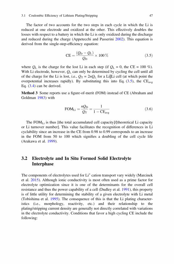
The factor of two accounts for the two steps in each cycle in which the Li isreduced at one electrode and oxidized at the other. This effectively doubles thelosses with respect to a battery in which the Li is only oxidized during the dischargeand reduced during the charge (Appetecchi and Passerini 2002). This equation isderived from the single-step-efficiency equation:
CE ¼ QD � QLð ÞQD
� 100% ð3:5Þ
where QL is the charge for the lost Li in each step (if QL = 0, the CE = 100 %).With Li electrode, however, QL can only be determined by cycling the cell until allof the charge for the Li is lost, i.e., QT = 2nQL for a Li||Li cell (at which point theoverpotential increases rapidly). By substituting this into Eq. (3.5), the CEavg
Eq. (3.4) can be derived.
Method 3 Some reports use a figure-of-merit (FOM) instead of CE (Abraham andGoldman 1983) with
FOMLi ¼ nQD
QT¼ 1
1� CEavgð3:6Þ
The FOMLi is thus [the total accumulated cell capacity]/[theoretical Li capacityor Li turnover number]. This value facilitates the recognition of differences in Licyclability since an increase in the CE from 0.98 to 0.99 corresponds to an increasein the FOM from 50 to 100 which signifies a doubling of the cell cycle life(Arakawa et al. 1999).
3.2 Electrolyte and In Situ Formed Solid ElectrolyteInterphase
The components of electrolytes used for Li+ cation transport vary widely (Marcineket al. 2015). Although ionic conductivity is most often used as a prime factor forelectrolyte optimization since it is one of the determinants for the overall cellresistance and thus the power capability of a cell (Dudley et al. 1991), this propertyis of little utility for determining the stability of a given electrolyte with Li metal(Tobishima et al. 1995). The consequence of this is that the Li plating character-istics (i.e., morphology, reactivity, etc.) and their relationship to theplating/stripping current density are generally not directly correlated with variationsin the electrolyte conductivity. Conditions that favor a high cycling CE include thefollowing:
3.1 Coulombic Efficiency of Lithium Plating/Stripping 47

1. uniform (compact) Li deposition which minimizes the surface area of the platedLi exposed to the electrolyte,
2. the formation of a stable passivation layer which protects the Li from furtherreactions with electrolyte components—if such a layer is elastic, then it canstretch and contract as necessary to conform to changes in the Li volume andmay aid in the redeposition of Li underneath such a layer thus reducing theexposure of fresh Li to the electrolyte (Aurbach 1999).
In particular, the deposition morphology is a function of the electrolyte solvent(s), salt(s), salt concentration, current density, temperature, and other factors.The SEI layer formed is often strongly influenced by contaminants or additives,even at the ppm level. Comparisons between the various studies reported in theliterature must take this into consideration. In addition, in contrast with graphiteanodes in which the passivating layer is supported on the graphite surface, thesurface layers that form on electrodeposited Li may be, and usually are, disruptedwhen the Li is stripped away during cell discharge (for nodular deposits) or lackelectrical contact with the current source (for needle-like deposits, which generatedead Li) (Fig. 2.17).
Although passivation films are known to form on the Li anode surface in bat-teries such as Li||SOCl2 primary cells, the role of this layer for Li stabilization wasemphasized by Dey (1977) and (Peled 1979, 1983; Peled et al. 1997) who dubbed ita “solid electrolyte interphase” (SEI). The contributing components to the SEI andthe effect that this has on Li plating/stripping will be discussed below. Note,however, that the study of the composition of the SEI layer is complicated by manyfactors, including the continuous evolution of the SEI during cycling/storage,changes that may occur from rinsing the surface (prior to ex situ characterization) ordue to high vacuum conditions and transformations of the components due to Ar+
sputtering during XPS depth analysis (Verma et al. 2010; Edström et al. 2006; Otaet al. 2004c). Thus, some caution should be exercised when interpreting the resultsreported in the diverse studies available in the literature.
Typically, as-received Li metal has surface coatings consisting principally ofLi2O (in contact with the Li) and an outer coating of LiOH and Li2CO3 (Hong et al.2004; Kanamura et al. 1992, 1994b, 1995b, d, 1997; Shiraishi et al. 1995). Once theLi contacts the electrolyte, these native layers are transformed by both chemical andelectrochemical reactions with the electrolyte components. The SEI films formed onLi in contact with an electrolyte are typically multi-layered with the speciesbecoming more inorganic in nature (i.e., more fully reduced) the closer they are tothe Li surface (Schechter et al. 1999). Over time, the interphasial layer may con-tinue to grow in thickness due to continuous reactions, but the SEI compositionmay also be continuously transformed (Aurbach et al. 1994a, 1995b). Impuritiessuch as dissolved gases (e.g., O2, CO2), H2O, or others are often the most reactiveconstituents of the electrolyte and, as such, these reactions may dominate thecharacteristics of the as-formed SEI layers. For solvents that are relatively reactive(e.g., esters and carbonates), solvent degradation is the next most important factor
48 3 High Coulombic Efficiency of Lithium Plating/Stripping …
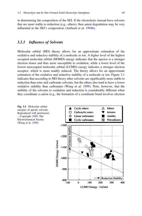
in determining the composition of the SEI. If the electrolytes instead have solventsthat are more stable to reduction (e.g., ethers), then anion degradation may be veryinfluential in the SEI’s composition (Aurbach et al. 1994b).
3.2.1 Influence of Solvents
Molecular orbital (MO) theory allows for an approximate estimation of theoxidative and reductive stability of a molecule or ion. A higher level of the highestoccupied molecular orbital (HOMO) energy indicates that the species is a strongerelectron donor and thus more susceptible to oxidation, while a lower level of thelowest unoccupied molecular orbital (LUMO) energy indicates a stronger electronacceptor, which is more readily reduced. The theory allows for an approximateestimation of the oxidative and reductive stability of a molecule or ion. Figure 3.1indicates that according to MO theory ether solvents are significantly more stable toreduction than ester and carbonate solvents, but the ethers also tend to have a loweroxidative stability than carbonates (Wang et al. 1999). Note, however, that thestability of the solvents to oxidation and reduction is considerably different whenthey coordinate a cation (e.g., the formation of a coordinate bond involves electron
Fig. 3.1 Molecular orbitalenergies of aprotic solvents.Reproduced with permission—Copyright 1999, TheElectrochemical Society(Wang et al. 1999)
3.2 Electrolyte and In Situ Formed Solid Electrolyte Interphase 49
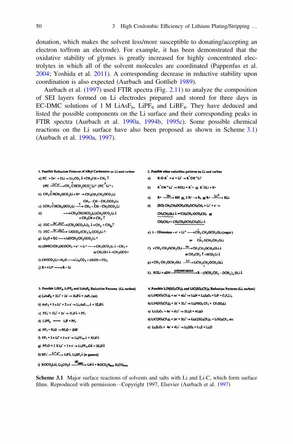
donation, which makes the solvent less/more susceptible to donating/accepting anelectron to/from an electrode). For example, it has been demonstrated that theoxidative stability of glymes is greatly increased for highly concentrated elec-trolytes in which all of the solvent molecules are coordinated (Pappenfus et al.2004; Yoshida et al. 2011). A corresponding decrease in reductive stability uponcoordination is also expected (Aurbach and Gottlieb 1989).
Aurbach et al. (1997) used FTIR spectra (Fig. 2.11) to analyze the compositionof SEI layers formed on Li electrodes prepared and stored for three days inEC-DMC solutions of 1 M LiAsF6, LiPF6 and LiBF4. They have deduced andlisted the possible components on the Li surface and their corresponding peaks inFTIR spectra (Aurbach et al. 1990a, 1994b, 1995c). Some possible chemicalreactions on the Li surface have also been proposed as shown in Scheme 3.1)(Aurbach et al. 1990a, 1997).
Scheme 3.1 Major surface reactions of solvents and salts with Li and Li-C, which form surfacefilms. Reproduced with permission—Copyright 1997, Elsevier (Aurbach et al. 1997)
50 3 High Coulombic Efficiency of Lithium Plating/Stripping …

3.2.1.1 Esters
Esters (Fig. 3.2) are attractive electrolyte solvents due to their high oxidative sta-bility and the very high conductivity of ester-based electrolytes, especially at lowtemperature. In addition to Li+ cation solvation via the ester carbonyl oxygen, whenmethyl formate (MF) is used, anion solvation via hydrogen bonding to the MFformyl proton also occurs which further reduces ionic association interactions(Plichta et al. 1987; Venkatasetty 1975; Tobishima et al. 1990).
Rauh and Brummer reported that slow gas evolution occurs when Li is contactedwith MF or methyl acetate (MA) and a white solid appears on the surface of the Li,whereas n-butyl formate (BF) was inert under the same conditions. LiAsF6 additionimproved the Li stability at elevated temperature, and the amount of gas evolutionfrom Li immersed in LiAsF6-ester electrolytes (heated up to 74 °C) indicated thatthe stability increased in the order MF > MA > ethyl acetate (EA) (Rauh andBrummer 1977b; Dampier and Brummer 1977). In general, the reactivity with Liincreased with increasing alkyl chain length (methyl to butyl) and on transitioningfrom formates to acetates to propionates (Herr 1990). Tobishima et al., however,instead found that a 1.5 M LiAsF6-MA electrolyte had a higher Li cycling CE thana 1.5 M LiAsF6-MF electrolyte—which is also the case for the electrolytes withmixtures of these solvents and EC (Tobishima et al. 1989, 1990, 1995). The reasonfor this disagreement is unclear. Electrolytes with MA corrode Li to a much greaterextent than those with PC, possibly due to the higher solubility of the reactionproducts resulting in the continuous exposure of Li to the solvent (Rauh andBrummer 1977b). It was found, however, that electrolytes in which MF or MA ismixed with a carbonate solvent such as DMC, DEC, or EC tend to have animproved CE (Tobishima et al. 1990; Plichta et al. 1989; Tachikawa 1993).
Herr (1990) indicated that esters may exist in both a stable keto form, as well as areactive enol form. The enol form may readily be reduced by Li. Since MF does not
Et O2 THF
G1
GBLMF MA EA
EC PC EMCDMC DEC
2MeTHF THP
G2DOL
Fig. 3.2 Structures ofselected aprotic solvents
3.2 Electrolyte and In Situ Formed Solid Electrolyte Interphase 51

form an enol, it cannot undergo such a reaction. Thus, MF is relatively stable to Li—in contrast to MA (Table 3.1.) (Herr 1990). Rauh (1975) indicated, however, thatdegradation may instead occur in a similar manner to the well-known reduction ofcarbonyl compounds by alkali metals. It is noteworthy that MF is susceptible tohydrolysis from trace amounts of H2O (in both acidic and basic solutions) (Marlieret al. 2005), forming formic acid, which can then be dehydrated to form H2O andCO; the H2O from this then reacts with additional MF. Residual acidic LiAsF5OHin LiAsF6 is believed to have catalyzed this reaction for MA-based electrolytes inearly studies. The use of highly purified LiAsF6 significantly decreased this reaction(Herr 1990). Hydrolysis can also occur in LiBF4-MF electrolytes, but it was sug-gested that the LiF present with the LiBF4 prevents the subsequent dehydration ofthe formic acid (Herr 1990). Thus, electrolytes with both LiAsF6 and LiBF4 in MFare more stable to Li than those without the latter salt as indicated by improvedcycling performance and by an increase in the time (from 1 to 10 months on storageof Li in the electrolyte at 74 °C) before a detectable amount of gas generation wasidentified (Herr 1990; Plichta et al. 1989; Honeywell 1975; Ebner and Lin 1987).Instead of degrading to H2O and CO, the formic acid may also directly react withthe Li since spectroscopic evaluations of the SEI indicate that the major MFreduction product is Li formate (Table 3.1) (Aurbach and Chusid (Youngman)1993; Ein-Eli and Aurbach 1996).
Cyclic esters, such as gamma-butyrolactone (GBL), have a high flash point andlow vapor pressure which reduces the flammability of electrolytes with such sol-vents (Hess et al. 2015). The use of 1 M LiX-GBL electrolytes (with LiAsF6,LiClO4, LiBF4, or LiCF3SO3) resulted in a relatively low Li cycling CE and the SEIformed in these electrolytes did not effectively passivate Li foil from continuousreactions on storage (Sazhin et al. 1994). This may be due to the relatively highsolubility of the GBL reaction products (Aurbach and Gottlieb 1989; Aurbach et al.1991a; Rendek et al. 2003; Aurbach 1989a, b). Kanamura et al. (1995d) noted thatwhen Li foil was immersed in a 1 M LiBF4-GBL electrolyte for 3 days, the elec-trode resistance initially decreased, but then increased steadily with time and theresulting SEI consisted predominantly of LiF with only a small amount of organiccompounds present. The SEI formed on Li foil with GBL electrolytes with LiAsF6,LiPF6, or LiClO4 also contained little to no organic components (Kanamura et al.1995b). This may again be due to the high solubility of the organic salts producedfrom GBL degradation (Table 3.1).
3.2.1.2 Alkyl Carbonates
As is the case for esters, alkyl carbonates (Fig. 3.2) are not overly stable to Lireduction (Fig. 3.1). Cyclic carbonates (e.g., EC and PC) are either reduced toLi2CO3 and ethylene (or propylene) or the carbonyl group is instead reduced toform a radical anion which then further reacts to form organic salts and polymers
52 3 High Coulombic Efficiency of Lithium Plating/Stripping …

Tab
le3.1
Reactionprod
uctsof
solvents,salts,andcontam
inantswith
Li(A
urbach
1999
)
Con
taminants/add
itives
Solvent
References
Dry
H2O
O2
CO2
HF
MF
Ein
Ely
and
Aurbach
(199
2)
mostly
HCO2Li,ROLi
(CH3O
Li)
HCO2Li
Li
oxides
+HCO2Li
HCO2Li+Li 2CO3
LiF
GBL
Aurbach
and
Gottlieb
(198
9),
Aurbach
(198
9a)
CH3(CH2)2C
OOLi,cyclic
di-Li
b-ketoestersalt
LiO(CH2)3C
O2Li
Liox
ides
ROCO2Lispecies
RCOOLi+Li 2CO3
LiF
DMC
Aurbach
etal.
(199
4a)
ROCO2Li(CH3O
CO2Li)
(Reactionof
ROCO2Li+H2O
)Li 2O
Li 2CO3
LiF+
ROCO2H
DEC
Aurbach
etal.
(198
7),
(199
5b)
CH3C
H2O
CO2Li+CH3C
H2O
Li
Li 2O2
EMC
Ein-Eliet
al.
(199
6)CH3O
Li,CH3O
CO2Li
LiOH-Li 2O
PMC
Ein-Eliet
al.
(199
7)CH3O
Li,CH3O
CO2Li,
CH3C
H2C
H2O
Li,
CH3C
H2C
H2O
CO2Li,
EC
Aurbach
etal.
(199
2),
(199
4a)
(CH2O
CO2Li)2+ethy
lene
Li 2CO3
LiF+
H2C
O3
PCAurbach
etal.
(198
7),
(199
4a)
CH3C
H(O
CO2Li)
CH2O
CO2Li+prop
ylene
ROCO2Li
ROCO2Li
ROCO2Li
LiF
THF
Aurbach
etal.
(198
8)ROLi,CH3(CH2)3O
Li
LiOH
Liox
ides
Li 2CO3
(con
tinued)
3.2 Electrolyte and In Situ Formed Solid Electrolyte Interphase 53

Tab
le3.1
(con
tinued)
Con
taminants/add
itives
Solvent
References
Dry
H2O
O2
CO2
HF
2MeT
HF
Malik
etal.
(199
0)Lipentox
ides
Li 2O
DOL
Aurbach
etal.
(199
0a,b)
CH3C
H2O
Li(CH2O
Li)2po
lyDOLspecies
ROCO2Li
DME
Aurbach
etal.
(198
8),
Aurbach
and
Grano
t(199
7)
ROLi(CH3O
Li)
Lialko
xides
ROLispecies
ROLispecies
Et-DME
Aurbach
and
Grano
t(199
7)CH3C
H2O
Li(CH2O
Li)2
G2
Aurbach
and
Grano
t(199
7)CH3O
Li,CH3O
CH2C
H2O
Li,
(CH2O
Li)2
THF-2M
eTHF
Aurbach
etal.
(199
5a)
THFredu
ctionprod
ucts
dominate
MF-DMC
Ein-Eliand
Aurbach
(199
6)
HCO2Lido
minates,ROCO2Li
(minor)
HCO2Li,
Li 2O-LiOH
Li 2CO3+red.
prod
ucts
LiF
MF-DEC
Ein-Eliand
Aurbach
(199
6)
LiO(CH2)3C
O2Li
Li 2CO3+red.
prod
ucts
MF-EC
Ein-Eliand
Aurbach
(199
6)
HCO2Li,ROCO2Lispecies
Li 2CO3,HCO3Li
ROCO2Li
HCO2Li
LiF
MF-PC
Ein-Eliand
Aurbach
(199
6)
LiOH-Li 2O
HCO2Li
Li 2CO3
(con
tinued)
54 3 High Coulombic Efficiency of Lithium Plating/Stripping …

Tab
le3.1
(con
tinued)
Con
taminants/add
itives
Solvent
References
Dry
H2O
O2
CO2
HF
MF-ethers
Ein-Eliand
Aurbach
(199
6)
HCO2Lido
minates
Li 2CO3,
ROCO2Li
Li 2CO3+red.
prod
ucts
EC-D
MC
Aurbach
etal.
(199
6)
EC-EMC
Ein-Eliet
al.
(199
6)ROCO2Li
Li 2O
ROCO2Li
EC-D
EC
Aurbach
etal.
(199
5b)
Li 2O-LiOH
EC-PC
Aurbach
etal.
(199
2)EC
redu
ctionprod
uctsdo
minate
ROCO2Li,
Li 2CO3
Li 2O,ROCO2Li
Li 2CO3,ROCO2Li
LiF
EC
orPC
-ethers
Aurbach
and
Gofer
(199
1)ROCO2Lispeciesdo
minate,
ROLi(m
inor)
LiOH-Li 2O
3.2 Electrolyte and In Situ Formed Solid Electrolyte Interphase 55
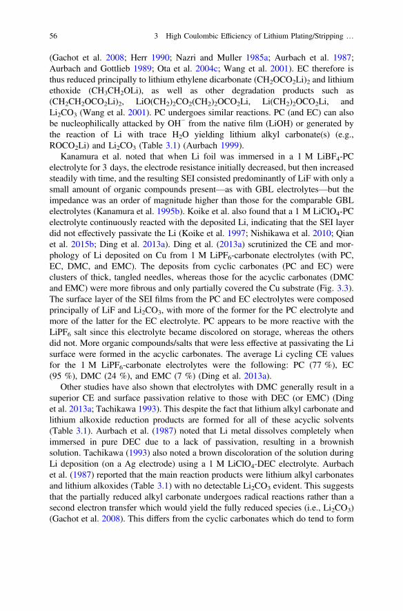
(Gachot et al. 2008; Herr 1990; Nazri and Muller 1985a; Aurbach et al. 1987;Aurbach and Gottlieb 1989; Ota et al. 2004c; Wang et al. 2001). EC therefore isthus reduced principally to lithium ethylene dicarbonate (CH2OCO2Li)2 and lithiumethoxide (CH3CH2OLi), as well as other degradation products such as(CH2CH2OCO2Li)2, LiO(CH2)2CO2(CH2)2OCO2Li, Li(CH2)2OCO2Li, andLi2CO3 (Wang et al. 2001). PC undergoes similar reactions. PC (and EC) can alsobe nucleophilically attacked by OH− from the native film (LiOH) or generated bythe reaction of Li with trace H2O yielding lithium alkyl carbonate(s) (e.g.,ROCO2Li) and Li2CO3 (Table 3.1) (Aurbach 1999).
Kanamura et al. noted that when Li foil was immersed in a 1 M LiBF4-PCelectrolyte for 3 days, the electrode resistance initially decreased, but then increasedsteadily with time, and the resulting SEI consisted predominantly of LiF with only asmall amount of organic compounds present—as with GBL electrolytes—but theimpedance was an order of magnitude higher than those for the comparable GBLelectrolytes (Kanamura et al. 1995b). Koike et al. also found that a 1 M LiClO4-PCelectrolyte continuously reacted with the deposited Li, indicating that the SEI layerdid not effectively passivate the Li (Koike et al. 1997; Nishikawa et al. 2010; Qianet al. 2015b; Ding et al. 2013a). Ding et al. (2013a) scrutinized the CE and mor-phology of Li deposited on Cu from 1 M LiPF6-carbonate electrolytes (with PC,EC, DMC, and EMC). The deposits from cyclic carbonates (PC and EC) wereclusters of thick, tangled needles, whereas those for the acyclic carbonates (DMCand EMC) were more fibrous and only partially covered the Cu substrate (Fig. 3.3).The surface layer of the SEI films from the PC and EC electrolytes were composedprincipally of LiF and Li2CO3, with more of the former for the PC electrolyte andmore of the latter for the EC electrolyte. PC appears to be more reactive with theLiPF6 salt since this electrolyte became discolored on storage, whereas the othersdid not. More organic compounds/salts that were less effective at passivating the Lisurface were formed in the acyclic carbonates. The average Li cycling CE valuesfor the 1 M LiPF6-carbonate electrolytes were the following: PC (77 %), EC(95 %), DMC (24 %), and EMC (7 %) (Ding et al. 2013a).
Other studies have also shown that electrolytes with DMC generally result in asuperior CE and surface passivation relative to those with DEC (or EMC) (Dinget al. 2013a; Tachikawa 1993). This despite the fact that lithium alkyl carbonate andlithium alkoxide reduction products are formed for all of these acyclic solvents(Table 3.1). Aurbach et al. (1987) noted that Li metal dissolves completely whenimmersed in pure DEC due to a lack of passivation, resulting in a brownishsolution. Tachikawa (1993) also noted a brown discoloration of the solution duringLi deposition (on a Ag electrode) using a 1 M LiClO4-DEC electrolyte. Aurbachet al. (1987) reported that the main reaction products were lithium alkyl carbonatesand lithium alkoxides (Table 3.1) with no detectable Li2CO3 evident. This suggeststhat the partially reduced alkyl carbonate undergoes radical reactions rather than asecond electron transfer which would yield the fully reduced species (i.e., Li2CO3)(Gachot et al. 2008). This differs from the cyclic carbonates which do tend to form
56 3 High Coulombic Efficiency of Lithium Plating/Stripping …
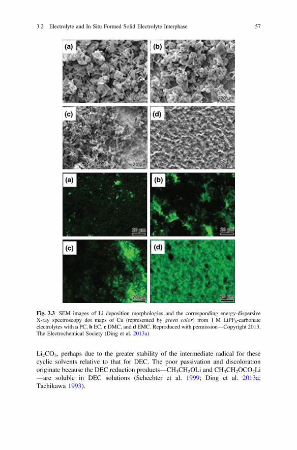
Li2CO3, perhaps due to the greater stability of the intermediate radical for thesecyclic solvents relative to that for DEC. The poor passivation and discolorationoriginate because the DEC reduction products—CH3CH2OLi and CH3CH2OCO2Li—are soluble in DEC solutions (Schechter et al. 1999; Ding et al. 2013a;Tachikawa 1993).
Fig. 3.3 SEM images of Li deposition morphologies and the corresponding energy-dispersiveX-ray spectroscopy dot maps of Cu (represented by green color) from 1 M LiPF6-carbonateelectrolytes with a PC, b EC, c DMC, and d EMC. Reproduced with permission—Copyright 2013,The Electrochemical Society (Ding et al. 2013a)
3.2 Electrolyte and In Situ Formed Solid Electrolyte Interphase 57
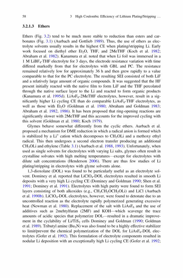
3.2.1.3 Ethers
Ethers (Fig. 3.2) tend to be much more stable to reduction than esters and car-bonates (Fig. 3.1) (Aurbach and Gottlieb 1989). Thus, the use of ethers as elec-trolyte solvents usually results in the highest CE when plating/stripping Li. Earlywork focused on diethyl ether Et2O, THF, and 2MeTHF (Koch et al. 1982;Abraham et al. 1982). Kanamura et al. noted that when Li foil was immersed in a1 M LiBF4-THF electrolyte for 3 days, the electrode resistance variation with timediffered markedly from that for electrolytes with GBL and PC. The resistanceremained relatively low for approximately 36 h and then grew rapidly to a valuecomparable to that for the PC electrolyte. The resulting SEI consisted of both LiFand a relatively large amount of organic compounds. It was suggested that the HFpresent initially reacted with the native film to form LiF and the THF percolatedthrough the native surface layer to the Li and reacted to form organic products(Kanamura et al. 1995d). LiAsF6-2MeTHF electrolytes, however, result in a sig-nificantly higher Li cycling CE than do comparable LiAsF6-THF electrolytes, aswell as those with Et2O (Goldman et al. 1980; Abraham and Goldman 1983;Abraham et al. 1982, 1986). It has been proposed that ring-opening reactions aresignificantly slower with 2MeTHF and this accounts for the improved cycling withthis solvent (Goldman et al. 1980; Koch 1979).
Glymes behave somewhat differently from the cyclic ethers. Aurbach et al.proposed a mechanism for DME reduction in which a radical anion is formed whichis stabilized by a Li+ cation which decomposes to CH3OLi and a methoxy ethylradical. This then undergoes a second electron transfer producing an additionalCH3OLi and ethylene (Table 3.1) (Aurbach et al. 1988, 1993). Unfortunately, whenused as single solvents for electrolytes with varying Li salts, glymes often result incrystalline solvates with high melting temperatures—except for electrolytes withdilute salt concentrations (Henderson 2006). There are thus few studies of Liplating/stripping in electrolytes with glyme solvents alone.
1,3-dioxolane (DOL) was found to be particularly useful as an electrolyte sol-vent. Dominey et al. reported that LiClO4-DOL electrolytes resulted in smooth Lideposits with a very high Li cycling CE (Dominey and Goldman 1990; Shen et al.1991; Dominey et al. 1991). Electrolytes with high purity were found to form SEIlayers consisting of both alkoxides (e.g., CH3CH2OCH2OLi) and LiCl (Aurbachet al. 1990b). LiClO4-DOL electrolytes, however, were found to detonate due to anuncontrolled reaction as the electrolyte rapidly polymerized generating excessiveheat (Newman et al. 1980). Replacement of the salt with LiAsF6 and the use ofadditives such as 2mehtylfuran (2MF) and KOH—which scavenge the traceamounts of acidic species that polymerize DOL—resulted in a dramatic improve-ment in the cyclability of Li/TiS2 cells Dominey and Goldman (1990; Goldmanet al. 1989). Tributyl amine (Bu3N) was also found to be a highly effective stabilizerto limit/prevent the chemical polymerization of the DOL for LiAsF6-DOL elec-trolytes (Gofer et al. 1992). This formulation of electrolyte components resulted innodular Li deposition with an exceptionally high Li cycling CE (Gofer et al. 1992;
58 3 High Coulombic Efficiency of Lithium Plating/Stripping …

Zaban et al. 1996; Dan et al. 1997; Aurbach and Moshkovich 1998; Zinigrad et al.2004; Aurbach 1999; Aurbach et al. 2002b; Mengeritsky et al. 1996a).
3.2.1.4 Mixed Solvents
Interestingly, mixing two or more solvents is found, in some instances, to result inan improved Li cycling CE relative to comparable single solvent electrolytes. Forexample, this is the case for MF and acyclic carbonate (Table 3.1) (Salomon 1989;Tachikawa 1993; Plichta et al. 1989) and the addition of DMC or DEC to MF-basedelectrolytes was found to improve the cycling efficiency of Li||LiCoO2 cells (Plichtaet al. 1989). Single solvent electrolyte studies with EC have not been extensivelystudied due to this solvent’s high melting temperature, but it has been widely usedas a co-solvent. The combination of EC and other solvents increases the Li cyclingCE, often quite significantly relative to the values for the single solvent electrolytes(including ethers), to average values >90 % (Fig. 3.4) (Tobishima et al. 1989,1990). The Li surface chemistry of EC-DMC and EC-DEC mixtures is dominatedby EC reduction, but this is more significant for Li passivation for the mixtures withDMC because the solvent reduction products are less soluble in DMC than in DEC(Schechter et al. 1999). In particular, Wang et al. found that electrolytes with EC,cyclic ethers, and lithium bis(perfluoroethylsulfonyl)imide (LiBETI) resulted in agood cycling performance, high thermal stability, high conductivity, and thehomogeneous deposition of nodular Li with a relatively high CE (>90 %) (Wanget al. 1999, 2000; Xianming et al. 2001; Ota et al. 2004a). After 50 plating/strippingcycles, the interphasial layer was much thinner for the electrolyte with the cyclicether (tetrahydropyranyl, THP) than for DME, carbonates (DMC and PC), and anester (GBL) (Fig. 3.5), which accounts for the significant variances in the Li cyclingperformance with these electrolytes (Fig. 3.6) (Ota et al. 2004a). A detailed analysisof the SEI concluded that the outer layer consisted of ROCO2Li (typical for EC),polymers, and LiF, while the inner layers contained Li2O and carbide species withC–Li bonds (Ota et al. 2004c). The polymers were determined to be lithium
Fig. 3.4 Average Li cyclingCE on a Pt substrate for1.5 M LiAsF6-solvent orLiAsF6-EC/solvent (1:1)electrolytes. Reproduced withpermission—Copyright 1990,Elsevier (Tobishima et al.1990)
3.2 Electrolyte and In Situ Formed Solid Electrolyte Interphase 59

ethylene dicarbonate with ethoxy units suggesting that these polymers result fromthe reduction of both EC and the cyclic ether. Such polymers with both carbonateand flexible ethoxy segments may create a stable, elastic layer that more effectively
Fig. 3.5 SEM images of Li deposited on a Ni substrate in a, f EC/THP (1/1), b, g EC/DME (1/1),c, h EC/DMC (1/1), d, i EC/PC (1/1) and e, j EC/GBL (1/1) electrolytes containing 1 M LiBETI.The left images a–e are the surface morphologies after the initial plating at 0.6 mA cm−2
(0.5 C cm−2). The right images f–j are the cross-sectional morphologies after 50 cycles at0.6/0.6 mA cm−2 (0.5 C cm−2) for the plating/stripping, respectively. Reproduced with permis-sion—Copyright 2004, The Electrochemical Society (Ota et al. 2004a)
60 3 High Coulombic Efficiency of Lithium Plating/Stripping …
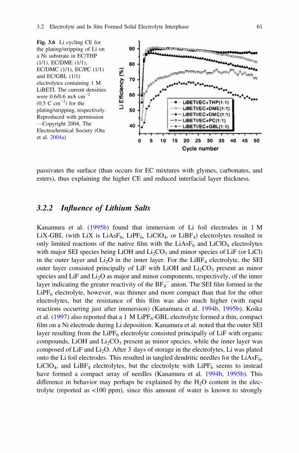
passivates the surface (than occurs for EC mixtures with glymes, carbonates, andesters), thus explaining the higher CE and reduced interfacial layer thickness.
3.2.2 Influence of Lithium Salts
Kanamura et al. (1995b) found that immersion of Li foil electrodes in 1 MLiX-GBL (with LiX is LiAsF6, LiPF6, LiClO4, or LiBF4) electrolytes resulted inonly limited reactions of the native film with the LiAsF6 and LiClO4 electrolyteswith major SEI species being LiOH and Li2CO3 and minor species of LiF (or LiCl)in the outer layer and Li2O in the inner layer. For the LiBF4 electrolyte, the SEIouter layer consisted principally of LiF with LiOH and Li2CO3 present as minorspecies and LiF and Li2O as major and minor components, respectively, of the innerlayer indicating the greater reactivity of the BF4
− anion. The SEI film formed in theLiPF6 electrolyte, however, was thinner and more compact than that for the otherelectrolytes, but the resistance of this film was also much higher (with rapidreactions occurring just after immersion) (Kanamura et al. 1994b, 1995b). Koikeet al. (1997) also reported that a 1 M LiPF6-GBL electrolyte formed a thin, compactfilm on a Ni electrode during Li deposition. Kanamura et al. noted that the outer SEIlayer resulting from the LiPF6 electrolyte consisted principally of LiF with organiccompounds, LiOH and Li2CO3 present as minor species, while the inner layer wascomposed of LiF and Li2O. After 3 days of storage in the electrolytes, Li was platedonto the Li foil electrodes. This resulted in tangled dendritic needles for the LiAsF6,LiClO4, and LiBF4 electrolytes, but the electrolyte with LiPF6 seems to insteadhave formed a compact array of needles (Kanamura et al. 1994b, 1995b). Thisdifference in behavior may perhaps be explained by the H2O content in the elec-trolyte (reported as <100 ppm), since this amount of water is known to strongly
Fig. 3.6 Li cycling CE forthe plating/stripping of Li ona Ni substrate in EC/THP(1/1), EC/DME (1/1),EC/DMC (1/1), EC/PC (1/1)and EC/GBL (1/1)electrolytes containing 1 MLiBETI. The current densitieswere 0.6/0.6 mA cm−2
(0.5 C cm−2) for theplating/stripping, respectively.Reproduced with permission—Copyright 2004, TheElectrochemical Society (Otaet al. 2004a)
3.2 Electrolyte and In Situ Formed Solid Electrolyte Interphase 61

influence HF formation and Li deposition morphology for a 1 M LiPF6-PC elec-trolyte (Qian et al. 2015a).
Ding et al. (2013a) reported substantial differences in the Li morphology whenplating from 1 M LiX-PC electrolytes. The average Li cycling CE values for the1 M LiX-PC electrolytes were as follows:
LiAsF6 95%ð Þ�LiBOB 93%ð Þ[LiDFOB 86%ð Þ[LiPF6 77%ð Þ[LiCF3SO3 73%ð Þ�LiClO4 72%ð Þ�LiTFSI 72%ð Þ�LiBF4 72%ð Þ�LiI 69%ð Þ
Interestingly, the morphology reported for the lithium bis(oxalate)borate(LiBOB) electrolyte was highly fibrous, but resulted in a high CE, whereas the Limorphology for the electrolytes with the other salts resembled entangled thickneedles or nodules, especially for the electrolytes that gave the highest CE values(Fig. 3.7) (Ding et al. 2013a). Aurbach has noted that a relatively high Li cyclingCE is achievable, even for a fibrous Li deposition morphology, if the SEI contains asignificant amount of Li2CO3 (Aurbach et al. 1992). This was attributed to the factthat the fibrous Li deposit formed with a Li2CO3 coating adhered very well to the
Fig. 3.7 SEM images of Li deposition morphologies from 1 M LiX-PC electrolytes witha LiBOB, b LiPF6, c LiAsF6, d LiTFSI, e LiI, f lithium difluoro(oxalato) borate (LiDFOB),g LiBF4, h LiCF3SO3, and i LiClO4. Reproduced with permission—Copyright 2013, TheElectrochemical Society (Ding et al. 2013a)
62 3 High Coulombic Efficiency of Lithium Plating/Stripping …

electrode surface, in contrast to fibrous deposits formed in other electrolytes thatlack Li2CO3 in the SEI layer. Although Li2CO3 might be expected to be a productfrom the reaction of the oxalate from the BOB− anion, an XPS analysis found thatLi2CO3 was absent. Alkyl oxalate and borate species may therefore instead accountfor the relatively high CE for the LiBOB electrolyte (Ding et al. 2013a).
For PC electrolytes with varying Li salts, Zaban and Aurbach (1995) differen-tiated between reactive salts (LiBF4, LiPF6, LiCF3SO3, and LiTFSI) and nonre-active salts (LiBr, LiClO4, and LiAsF6). When the nonreactive salts were used, theLi-electrolyte interface was stable upon storage, whereas the interfacial resistancecontinuously increased upon storage for electrolytes with reactive salts and wasstrongly dependent upon salt concentration. Geronov et al. (1982), however,reported that the Li-electrolyte resistance for 0.5 M LiX-PC electrolytes didincrease over time, but to a much lesser extent for the electrolyte with LiAsF6 thanfor the one with LiClO4. Kanamura et al. (1997) also found that the SEI formed onLi immersed in a 1 M LiClO4-DEC electrolyte became thick and was composed ofa mixture of LiOH, Li2CO3, alkyl carbonates, alkoxides, and Li2O, whereasimmersion of Li in a 1 M LiPF6-DEC electrolyte resulted in a compact SEI com-posed mostly of an inner layer of Li2O and an outer layer of LiF (Figs. 3.8 and 3.9).
Wang et al. (1999) noted that for 1 M LiX-EC/THF (1/1) electrolytes, the Licycling CE increased in the order as follows:
LiTFSI � LiBETI[LiClO4 [LiBF4 [LiPF6
These authors found that the SEI formed during the plating/stripping from theLiPF6 electrolyte contained a significant amount of LiF and residual Li was presentafter the stripping step, whereas very little LiF was present for the LiTFSI elec-trolyte and no residual Li was found after the stripping step. These authors alsoreported an improved CE for LiTFSI- and LiBETI-based electrolytes relative toLiPF6-based electrolytes with EC/DME and EC/DEC mixed solvents (Wang et al.2000a). Zaban et al. (1996) examined the resistance of the Li-electrolyte interfaceupon storage in 1 M LiX-EC/DEC (3/1) electrolytes. Notably, the resistance of theinterface was an order of magnitude higher for the electrolytes with LiPF6 andLiBF4 relative to those with LiAsF6 and LiClO4 (Figs. 3.10 and 3.11).
Tobishima et al. (1995) found that the CE for 1 M LiX-EC/2MeTHF (1:1)electrolytes increased in the following order:
LiAsF6 [LiClO4 [LiBF4 [LiSbF6 [LiCF3SO3 [LiPF6
Herr (1990) reported that the CE for 1 M LiX-MF electrolytes increased in thefollowing order:
LiAsF6 [LiClO4 [LiPF6 [LiBF4
3.2 Electrolyte and In Situ Formed Solid Electrolyte Interphase 63

Fig. 3.8 XPS spectra for Li foil immersed in 1 M LiX-DEC for 240 min: a LiClO4 and b LiPF6.Reproduced with permission—Copyright 1997, The Electrochemical Society (Kanamura et al.1997)
Fig. 3.9 Schematic modelfor the surface products on Lifoil immersed in 1 MLiX-DEC: a LiClO4 andb LiPF6. Reproduced withpermission—Copyright 1997,The Electrochemical Society(Kanamura et al. 1997)
64 3 High Coulombic Efficiency of Lithium Plating/Stripping …

while the values for 1 M LiX-PC electrolytes increased in the following order (Herr1990):
LiAsF6 [LiClO4 [LiBF4 �LiPF6:
The electrolyte salt thus plays a prominent role in the Li cycling performance.The strong disparity in behavior noted for LiAsF6 and LiPF6, despite their structuralsimilarities, may be due to the substantial differences in the reductive stability of theanions. A study of THF and sulfolane electrolytes with LiAsF6 and LiPF6 foundthat AsF6
− tend to be reduced to AsF3 as follows:
AsF�6 þ 2e� $ AsF3 þ 3F�
F� þLiþ $ LiF
The LiF is insoluble in the electrolyte and thus remains on the electrode surface(i.e., becomes part of the SEI). In contrast, the PF6
− anion is not readily reduced,but this anion does disproportionate as follows:
PF�6 $ PF5 þ F�
Fig. 3.10 Multilayer model of the Li-electrolyte interface and the equivalent circuit analog fit.Layers a–c may be thought of as the SEI, while the porous interphase is the interphasial layerwhich includes the dead or mossy Li. Reproduced with permission—Copyright 1996, TheAmerican Chemical Society (Zaban et al. 1996)
3.2 Electrolyte and In Situ Formed Solid Electrolyte Interphase 65
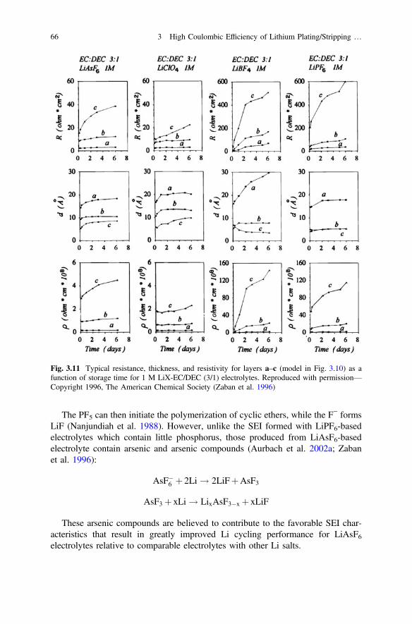
The PF5 can then initiate the polymerization of cyclic ethers, while the F− formsLiF (Nanjundiah et al. 1988). However, unlike the SEI formed with LiPF6-basedelectrolytes which contain little phosphorus, those produced from LiAsF6-basedelectrolyte contain arsenic and arsenic compounds (Aurbach et al. 2002a; Zabanet al. 1996):
AsF�6 þ 2Li ! 2LiFþAsF3
AsF3 þ xLi ! LixAsF3�x þ xLiF
These arsenic compounds are believed to contribute to the favorable SEI char-acteristics that result in greatly improved Li cycling performance for LiAsF6electrolytes relative to comparable electrolytes with other Li salts.
Fig. 3.11 Typical resistance, thickness, and resistivity for layers a–c (model in Fig. 3.10) as afunction of storage time for 1 M LiX-EC/DEC (3/1) electrolytes. Reproduced with permission—Copyright 1996, The American Chemical Society (Zaban et al. 1996)
66 3 High Coulombic Efficiency of Lithium Plating/Stripping …
3.2.3 Influence of Additives
A diverse range of additives have been added to electrolytes—either intentionallyor accidentally as contaminants—which are often the most reactive components ofthe electrolyte and thus dominate the initial SEI formation even when present onlyin trace amounts. The most commonly studied contaminants are H2O and O2, whileCO2 has received intense focus as an additive.
3.2.3.1 H2O and HF
H2O is a frequent electrolyte contaminant. As such, many studies have beendevoted to scrutinizing its influence on the Li plating morphology and cyclingbehavior. Small amounts of H2O are often found to improve the Li cycling CE, butan excess amount of H2O instead degrades the Li cycling CE (Malik et al. 1990;Rauh and Brummer 1977b; Aurbach and Granot 1997; Qian et al. 2015a; Selim andBro 1974; Rauh and Brummer 1977a; Togasaki et al. 2014; Arakawa et al. 1999).When H2O is present in carbonate-based electrolytes, its reaction suppresses thesolvent and anion reduction reactions due to the formation of Li2CO3 (Schechteret al. 1999; Aurbach et al. 1995b; Zaban et al. 1996; Nazri and Muller 1985c):
2ROCO2LiþH2O ! 2ROHþCO2 þLi2CO3
The alcohol produced is likely to be soluble in the electrolyte. The dissolvedCO2 may react with Li2O or LiOH to form Li2CO3, or alternatively with a lithiumalkoxide to form a lithium alkylcarbonate species. The Li2CO3 is insoluble inaprotic solvents and thus becomes part of the SEI layer. In ether-based electrolytes,however, H2O does not react with the alkoxides formed, but it does solvate thesesurface species which facilitates the diffusion of the H2O to the Li surface to formLiOH and Li2O accompanied by H2 generation (Zaban et al. 1996; Nazri andMuller 1985c; Malik et al. 1990):
2H2Oþ 2Li ! 2LiOHþH2
2LiOHþ 2Li ! 2Li2OþH2
Therefore, small amounts of H2O tend to increase the Li cycling CE forPC-based electrolytes, but decreases the CE for ether-based electrolytes (Aurbachet al. 1989).
Although the ClO4− anion is relatively stable to hydrolysis, this is not the case
for PF6− and BF4
− (Kanamura et al. 1995b, d; Qian et al. 2015a):
MF�n þH2O ! F� þ 2HFþMOFn�3 M ¼ P or Bð Þ
3.2 Electrolyte and In Situ Formed Solid Electrolyte Interphase 67
The F− can then react with a Li+ cation to form LiF, while the HF can react withseveral other compounds present in electrolyte or SEI layer according to the fol-lowing reactions:
LiOHþHF ! LiFþH2O
Li2Oþ 2HF ! 2LiFþH2O
2Liþ 2HF ! 2LiFþH2
ROCO2LiþHF ! LiFþROCO2H
Li2CO3 þHF ! LiFþLiHCO3
LiHCO3 þHF ! LiFþH2CO3
The ROCO2H and H2CO3 are likely to be soluble in the electrolyte. Thus,electrolytes with LiPF6, especially when a small amount of H2O is present, oftenhave a compact SEI layer consisting predominantly of LiF with relatively littleorganic species present. It is important to note that this does not necessarily meanthat reactions with the solvent are largely prevented (although this may occur if thesurface passivation is effective) since the products of such solvent reactions maycontinuously react with HF to form soluble species (which may then influence thecathode reactions). This LiF-dominant SEI layer on Li metal results in the uniformformation of Li nuclei underneath this inorganic layer which then may grow into analigned array of Li nanorods (which is covered by an SEI layer consisting of LiFand perhaps some Li2O) (Fig. 2.16) with a flat, mirror-like surface that results in ablue texture-coloring (Qian et al. 2015a).
Kanamura and Takehara reported that the direct addition of HF (e.g., to a 1 MLiClO4-PC electrolyte) resulted in Li (plated on Ni) with a smooth, uniformdeposition morphology that also had a blue color (Kanamura et al. 1994a; Takehara1997). This is due to the formation of a thin surface coating of LiF (Kanamura et al.1994a, 1995a, 1996, 2000; Takehara 1997; Shiraishi et al. 1997; Lee et al. 2005).The same results were obtained with electrolytes having different carbonate sol-vents and Li salts (Shiraishi et al. 1997). These authors indicated that the Li had ahemispherical form, but an examination of the SEM images suggests that thiscorresponds to the rounded tops of aligned arrays of Li nanorods (Kanamura et al.1994a, 1995a; Shiraishi et al. 1997, 1999a; Yoon et al. 2008), as was noted above.Despite this favorable Li deposition morphology, the Li cycling CE in the 1 MLiClO4-PC electrolyte with added HF was rather low (<90 %) (Kanamura et al.2000; Shiraishi and Kanamura 1998; Shiraishi et al. 1999a; Yoon et al. 2008). Thislow efficiency may be attributed to a coating on the surface of each of the nanorodsgrowing outward. After stripping the Li, a thick residual film remained on theelectrode. This negatively impacted the subsequent depositions due to the accu-mulation of this interphasial layer (Shiraishi et al. 1999b; Yoon et al. 2008).
68 3 High Coulombic Efficiency of Lithium Plating/Stripping …

3.2.3.2 O2 and N2
The addition of dissolved O2 tended to improve the Li cycling efficiency (Maliket al. 1990; Koch and Young 1978). In aprotic electrolytes, the reduction of O2
(above 1.8 V vs. Li/Li+—Fig. 3.12) results in a metastable superoxide ion or aperoxide (Pletcher et al. 1994; Aurbach et al. 1991b; Aurbach 1989a)
O2 þLi ! LiO2
O2 þ 2Li ! Li2O2
According to the recent Li-air battery studies, LiO2 is reactive to carbonatesolvents to Li2CO3 and lithium alkylcarbonate, while it is relatively stable in ethersand has certain solubility. These oxides should be highly insoluble in carbonate andether solvents.
The reactivity of dissolved N2 toward Li at low potential was studied in N2-saturated 2MeTHF solutions (Malik et al. 1990). The reactivity to form Li3N wasrather low suggesting that N2 is probably not reactive enough to compete with othersolution components for the SEI formation. Only modest improvements to the CEwere noted for an N2-saturated 1 M LiAsF6-THF electrolyte (Koch and Young1978). Another study in which Li was exposed to dried air (i.e., a dry room),however, determined that the surface coating consisted of both Li2CO3 and Li3Nwhich improved the Li cycling CE relative to Li stored in Ar (Momma et al. 2011).Exposing Li directly to N2 gas also produced a Li3N layer which, when cycled in a1 M LiPF6-EC/DMC (1/1) electrolyte, resulted in stable cycling performance,suggesting that the Li3N layer was durable, but the Li cycling CE was low (<90 %)for this electrolyte (Wu et al. 2011).
2MF
VC VECFEC
Fig. 3.12 Structures ofselected organic additives
3.2 Electrolyte and In Situ Formed Solid Electrolyte Interphase 69

3.2.3.3 CO2 and SO2
Brummer et al. noted in 1977 that the addition of SO2 improved the Li cycling CEof electrolytes (Rauh and Brummer 1977a, b; Dampier and Brummer 1977). Thisadditive, however, did not effectively passivate the Li surface and its toxicity haslimited its use. The use of CO2, however, has been extensively studied as anadditive. This reacts with surface species to form Li2CO3 which becomes a majorsurface species which, in turn, often greatly improves the Li cycling CE (Ein-Eliand Aurbach 1996; Aurbach and Chusid (Youngman) 1993; Ein Ely and Aurbach1992; Malik et al. 1990; Osaka et al. 1997b, c; Besenhard et al. 1993; Fujieda et al.1994; Momma et al. 1995; Gan and Takeuchi 1996). Li2CO3 is one of the mosteffective Li passivating species for preventing Li corrosion and the formation ofdead Li (Besenhard and Eichinger 1976). Although the Li deposition morphologyremains that of kinked needles, these adhere well to the electrode surface thuspreventing the loss of electrical contact (Aurbach et al. 1992). Note, however, thatthis plating/stripping behavior will still result in the continuous buildup of aninterphasial layer due to the residue from the needle-like SEI layers once the Li isstripped and then re-plated since the Li does not redeposit in the empty needlehusks. In addition, excessive amounts of CO2 can degrade the CE, especially forLiAsF6-ether electrolytes, which tend to generate a stable SEI layer, resulting in avery high Li cycling CE (Malik et al. 1990; Koch and Young 1978). Of note,Aurbach et al. (1992) found that the use of Al2O3 as a drying agent for EC or PCproduced CO2 and thus storage of such electrolytes over Al2O3 will increase the Licycling CE considerably.
3.2.3.4 Other Additives
Numerous other additives have been utilized. These include nitrous oxides (e.g.,N2O and CH3NO2) (Dampier and Brummer 1977; Rauh and Brummer 1977a, b;Uchiyama et al. 1987; Besenhard et al. 1993), trialkylamines (Aurbach et al. 2002a;Dan et al. 1997; Gofer et al. 1992; Herlem et al. 1996), aromatic compounds (e.g.,benzene, toluene, and furans/thiophenes (especially 2MF) (see Fig. 3.12) (Abraham1985; Morita et al. 1992; Geronov et al. 1989; Goldman et al. 1989; Halpert et al.1994; Malik et al. 1990; Matsuda 1993; Abraham et al. 1984; Dominey andGoldman 1990; Ishikawa et al. 1994; Matsuda and Morita 1989; Matsuda andSekiya 1999; Surampudi et al. 1993; Wu et al. 2013; Saito et al. 1997; Choi et al.2007a; Peled et al. 1989; Choi et al. 2008; Lane et al. 2010a), and reactive car-bonates (fluoroethylene carbonate, FEC and vinylene carbonate, VC) (Song et al.2013a; Mogi et al. 2002c; Roberts et al. 2014; Guo et al. 2015; Ota et al. 2004b, d).FEC, VC, and vinylethylene carbonate (VEC) (see Fig. 3.12) have also been usedas single solvents for 1 M LiPF6-carbonate electrolytes which resulted in sub-stantial differences in the Li morphology (Fig. 3.13) and comparable CE values of97–98 % (compare with Fig. 3.3) (Ding et al. 2013a).
70 3 High Coulombic Efficiency of Lithium Plating/Stripping …
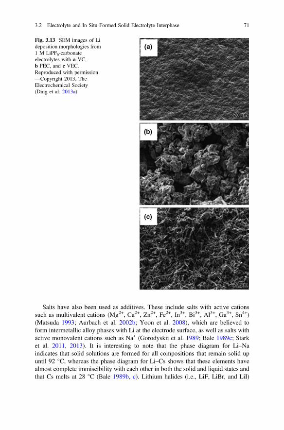
Salts have also been used as additives. These include salts with active cationssuch as multivalent cations (Mg2+, Ca2+, Zn2+, Fe2+, In3+, Bi3+, Al3+, Ga3+, Sn4+)(Matsuda 1993; Aurbach et al. 2002b; Yoon et al. 2008), which are believed toform intermetallic alloy phases with Li at the electrode surface, as well as salts withactive monovalent cations such as Na+ (Gorodyskii et al. 1989; Bale 1989c; Starket al. 2011, 2013). It is interesting to note that the phase diagram for Li–Naindicates that solid solutions are formed for all compositions that remain solid upuntil 92 °C, whereas the phase diagram for Li–Cs shows that these elements havealmost complete immiscibility with each other in both the solid and liquid states andthat Cs melts at 28 °C (Bale 1989b, c). Lithium halides (i.e., LiF, LiBr, and LiI)
Fig. 3.13 SEM images of Lideposition morphologies from1 M LiPF6-carbonateelectrolytes with a VC,b FEC, and c VEC.Reproduced with permission—Copyright 2013, TheElectrochemical Society(Ding et al. 2013a)
3.2 Electrolyte and In Situ Formed Solid Electrolyte Interphase 71

have also been used as additives (Lu et al. 2014, 2015; Ishikawa et al. 1994;Besenhard 1977). Both LiF and LiBr have a low to negligible solubility in aproticelectrolytes, but LiI has an appreciable solubility. It was suggested, however, thatthe I− anion absorbs on the Li surface. These halide salts cannot be further reduced,and so their presence on the Li surface may hinder or prevent reaction of the Li withother electrolyte components. Li salts with reactive anions (LiBOB, LiDFOB, andLiNO3) have also been used (Xiong et al. 2011; Wu et al. 2014; Guo et al. 2015; Liet al. 2015; Zhang 2013a), as have salts that combine these features (MgI2, AlI3,and SnI2) (Ishikawa et al. 1994; Matsuda et al. 1995; Ishikawa et al. 1997, 1999b,2003, 2005).
3.2.4 Influence of Ionic Liquids
Many ionic liquids (ILs) with tetraalkylammonium (e.g., NRRRR+ , PY1R
+ , and PI1R+ )
and tetraphosphonium (PRRRR+ ) cations have very high electrochemical stability
windows. For example, for the N1116TFSI IL (with trimethylhexylammoniumcations), this is in excess of 5 V (0–5 V vs. Li/Li+) when cycled with electrodessuch as Pt, Al, or glassy carbon (Zheng et al. 2005). Notably, however, the elec-trochemical stability is strongly dependent on the electrode material asoxidation/reduction reactions were evident within this voltage range when Ni, Cu,and acetylene black were used instead (Zheng et al. 2005). Typically, the reductivestability of an IL is determined by the identity of the organic cation. ILs with1-alkyl-3-methylimidazolium (e.g., IM102
+) cations exhibit poor reductive stabilitydue to the high reactivity of the C-2 proton on the cation’s ring (Best et al. 2010;Matsumoto et al. 2006; Sano et al. 2013). It thus follows that ILs with1-alkyl-2,3-dimethylimidazium (e.g., IM113
+) cations are more stable to reduction(although the C-4 and C-5 protons are still somewhat acidic), while tetraalkylam-monium and tetraalkylphosphonium cations are the most stable (Best et al. 2010;Matsumoto et al. 2006; Seki et al. 2006b).
In general, neat tetraalkylammonium-based ILs display a reductive current in itscyclic voltammetry curve just prior to the potential at which Li plating initiates.This would suggest that these ILs are unsuitable for this application (Bhatt et al.2010), but when a Li salt (e.g., LiBF4, LiPF6, and LiTFSI) is dissolved in an IL(with either FSI− or TFSI− anions), a substantial extension of the cathodic stabilitylimit occurs which enables the highly reversible plating/stripping of Li metal (Bestet al. 2010; Matsumoto et al. 2006). The stabilization effects for the different Li saltswere found to be comparable, irrespective of the Li salt used (Girard et al. 2015; Liuet al. 2014a; Best et al. 2010). The influence of temperature on electrochemicalstability is often neglected. Few available studies explore this, but one study foundthat as the temperature increased, the reductive stability potential range of theelectrolyte contracted resulting in the overlap of the Li plating process with elec-trolyte degradation and thus significant IL decomposition occurred at * 80 °C(Best et al. 2010).
72 3 High Coulombic Efficiency of Lithium Plating/Stripping …
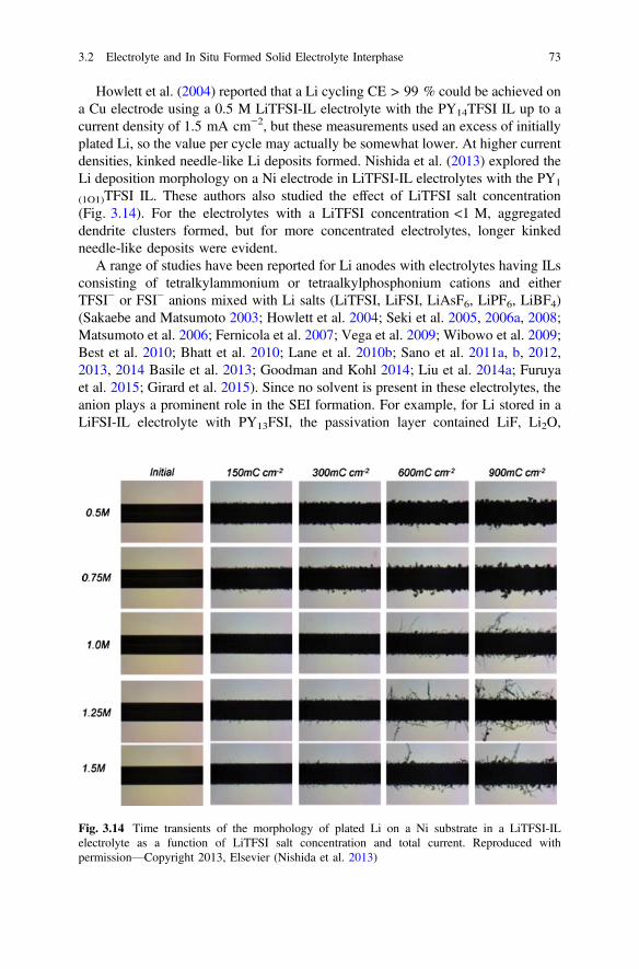
Howlett et al. (2004) reported that a Li cycling CE > 99 % could be achieved ona Cu electrode using a 0.5 M LiTFSI-IL electrolyte with the PY14TFSI IL up to acurrent density of 1.5 mA cm−2, but these measurements used an excess of initiallyplated Li, so the value per cycle may actually be somewhat lower. At higher currentdensities, kinked needle-like Li deposits formed. Nishida et al. (2013) explored theLi deposition morphology on a Ni electrode in LiTFSI-IL electrolytes with the PY1
(1O1)TFSI IL. These authors also studied the effect of LiTFSI salt concentration(Fig. 3.14). For the electrolytes with a LiTFSI concentration <1 M, aggregateddendrite clusters formed, but for more concentrated electrolytes, longer kinkedneedle-like deposits were evident.
A range of studies have been reported for Li anodes with electrolytes having ILsconsisting of tetralkylammonium or tetraalkylphosphonium cations and eitherTFSI− or FSI− anions mixed with Li salts (LiTFSI, LiFSI, LiAsF6, LiPF6, LiBF4)(Sakaebe and Matsumoto 2003; Howlett et al. 2004; Seki et al. 2005, 2006a, 2008;Matsumoto et al. 2006; Fernicola et al. 2007; Vega et al. 2009; Wibowo et al. 2009;Best et al. 2010; Bhatt et al. 2010; Lane et al. 2010b; Sano et al. 2011a, b, 2012,2013, 2014 Basile et al. 2013; Goodman and Kohl 2014; Liu et al. 2014a; Furuyaet al. 2015; Girard et al. 2015). Since no solvent is present in these electrolytes, theanion plays a prominent role in the SEI formation. For example, for Li stored in aLiFSI-IL electrolyte with PY13FSI, the passivation layer contained LiF, Li2O,
Fig. 3.14 Time transients of the morphology of plated Li on a Ni substrate in a LiTFSI-ILelectrolyte as a function of LiTFSI salt concentration and total current. Reproduced withpermission—Copyright 2013, Elsevier (Nishida et al. 2013)
3.2 Electrolyte and In Situ Formed Solid Electrolyte Interphase 73

LiOH, and FSI− decomposition products (Budi et al. 2012). A similar complexmixer of species was proposed for the degradation of the TFSI− anion (Howlettet al. 2004). But a significant difference was noted when the cell was cycled as theSEI then did not contain the species present in the native Li SEI layer (i.e., Li2O,LiOH, and Li2CO3), but instead had significant quantities of species associated withthe cation (Howlett et al. 2006).
During the cycling of Li||Li symmetric cells with IL-based electrolytes, voltageinstabilities were frequently noted (Basile et al. 2013; Best et al. 2010; Bhatt et al.2010, 2012; Lane et al. 2010b). This was initially attributed to a “welding”mechanism for Li dendrites (Fig. 3.15) (Lane et al. 2010b), but later it was pro-posed that a Li electrode surface reorganization was instead occurring (Basile et al.2013). This latter explanation is very plausible since a similar SEI layer disruptionwas proposed for the reduction in the polarization for Li plating/stripping withpolymer electrolytes (Appetecchi and Passerini 2002). Unlike for a polymer elec-trolyte where the formation of a resistive interface is rather slow due to the lack ofmobility of the electrolyte, for an IL-based electrolyte—especially one with reactive
Fig. 3.15 a Time versusvoltage curves forconstant-current cycling of aLi||Li symmetrical cell with a0.4 M LiFSI-IL electrolytewith MO14FSI cycled at acurrent density of0.2 mA cm−2 andb schematic illustrationshowing the steps in apossible dendrite weldingprocess: 1 accumulateddendrites, 2 dendrites connect,causing a short circuit, 3electrical current flowsthrough granular conductionpath creating hot spots atgrain boundaries, and 4 shortcircuit removed due to a fuseeffect with remainingdendrites unified into a singlemetallic structure withmetallic connection to thebase electrode. Reproducedwith permission—Copyright2010, The AmericanChemical Society (Lane et al.2010b)
74 3 High Coulombic Efficiency of Lithium Plating/Stripping …

FSI− anions or other electrolyte components—as the interphasial layer is disrupted,reactions with the exposed Li accelerate, resulting in an increase in the polarization.This buildup and disruption readily explains the chaotic polarization voltage vari-ations during cycling.
3.2.5 Importance of Electrolyte Concentration
In recent years, use of highly concentrated electrolyte has proved to be a veryefficient approach to suppress Li dendrite growth and enhance the CE of Li cycling.As the salt concentration increases, there is less free (uncoordinated) solvent presentin the electrolyte. Thus, the SEI composition may be more reflective of the anion’sreductive properties. However, in highly concentrated electrolytes there is notenough solvent available to fully coordinate the Li+ cations. Thus, cations arecoordinated to solvent molecules and anions, with the anions typically coordinatedto multiple Li+ cations, giving a network-like electrolyte solution structure. Just ascoordinated solvent molecules are more susceptible to reduction, so too are coor-dinated anions.
Early work in this field was focused on the use of concentrated electrolyte tostabilize graphite electrodes used in Li-ion batteries. Recently, it has also been usedin Li metal batteries with excellent results. Because graphite has a reductionpotential very close to that of a Li metal anode, general characteristics of theconcentrated electrolyte used with graphite are similar to those used for Li metalanodes. Therefore, it is very useful to understand the general properties of con-centrated electrolytes when they are used with graphite.
McKinnon and Dahn demonstrated in 1985 that co-intercalation of PC intolayered materials intercalated with Li can be reduced with concentrated elec-trolytes (McKinnon and Dahn 1985). McOwen et al. (2014) used highly con-centrated electrolytes containing carbonate solvents with LiTFSI to determine theinfluence of eliminating bulk solvent (i.e., uncoordinated to a Li+ cation) onelectrolyte properties. The phase behavior of LiTFSI-EC mixtures indicates thattwo crystalline solvates form—LiTFSI-(EC)3 and LiTFSI-(EC)1. A Raman spec-troscopic analysis of the EC solvent bands for the 3-1 and 2-1 LiTFSI- EC liquidelectrolytes indicates that *86 and 95 %, respectively, of the solvent is coordi-nated to the Li+ cations. This extensive coordination results in significantlyimproved anodic oxidation and thermal stabilities as compared with more dilute(i.e., 1 M) electrolytes. Further, while dilute LiTFSI-EC electrolytes extensivelycorrode the Al current collector at high potential, the concentrated electrolytes donot. Although the ionic conductivity of concentrated LiTFSI-EC electrolytes issomewhat low relative to the current state-of-the-art electrolyte formulations usedin commercial Li-ion batteries, using an EC-DEC mixed solvent instead of pureEC markedly improves the conductivity.
3.2 Electrolyte and In Situ Formed Solid Electrolyte Interphase 75

Recently, Yamada et al. (2010, 2013, 2014a, b) have done extensive work on useof various concentrated electrolytes to improve the stability of graphite anode underdifferent conditions. They found that a superconcentrated ether electrolyte can leadto ultrafast Li+ intercalation into graphite, even exceeding that in a currently usedcommercial electrolyte. This discovery is important for fast-charging Li-ion bat-teries far beyond present technologies (Yamada et al. 2013). They also investigatedthe behavior of electrochemical lithium intercalation into graphite in DMSO-basedelectrolytes, including lithium salt-concentrated solutions and binary solutions withDMC. Raman spectra of these solutions showed that the solvation number ofDMSO molecules toward Li+ cations (NDMSO) decreased from 4.2 in a conventionalsolution to around 2 in the salt-concentrated solution and the binary solution.A comparison between the behavior of graphite and the NDMSO values has clarifiedthat the NDMSO value of 3 is a criterion for determining whether the intercalation ofLi+ ions or solvated Li+ ions occurs. A series of results suggests that the decrease inthe solvation number of the relevant solvents toward Li+ ion can suppress theco-intercalation of solvents into graphite (Yamada et al. 2010). They also found thata dilute electrolyte (e.g., 1 M) of sulfoxide, ether, and sulfone results in solventco-intercalation and/or severe electrolyte decomposition at a graphite electrode,whereas their superconcentrated electrolyte (e.g., > 3 M) allows for highly rever-sible Li intercalation into graphite. A unique coordination structure in the super-concentrated solution and an anion-based inorganic SEI film on the cycled graphiteelectrode have been identified which would be the origin of the reversible graphitenegative electrode reaction without EC (Yamada et al. 2014a).
Yamada and Tateyama (2014) also investigated the fundamental mechanismbehind the enhanced stability of highly concentrated electrolyte toward graphiteanode. They report enhanced reductive stability of a superconcentrated acetonitrile(AN) solution (>4 M). Applying it to a battery electrolyte, they demonstrate, for thefirst time, reversible Li intercalation into a graphite electrode in areduction-vulnerable AN solvent. First-principle calculations combined withspectroscopic analyses reveal that the peculiar reductive stability arises frommodified frontier orbital characters unique to such superconcentrated solutions, inwhich all solvents and anions coordinate to Li+ cations to form a fluid polymericnetwork of anions and Li+ cations. To identify the solution structure providing theunusual reductive stability with a surface film derived from bis(trifluoromethane-sulfonyl)amide (TFSA or TFSI), Raman spectra were obtained for LiTFSI/ANsolutions at various Li salt concentrations (Fig. 3.16a, b). In dilute solutions, astable solvation structure around Li+ is reported to be 3- or 4-fold coordination(Fig. 3.16c). Further increasing the Li salt concentration decreases free AN mole-cules and instead increases the Li+-solvating AN molecules. At 4.2 M (super-highconcentration), where unusual reductive stability was observed, there is only a peakfor Li+-solvating AN molecules, indicating that all the AN molecules coordinate toLi+. A series of spectroscopic analyses show that the structure of thesalt-superconcentrated solution is characterized by a fluid polymeric network ofmutually interacting TFSI− anions and Li+ cations in the presence of two ANmolecules solvating each Li+. This peculiar structural feature is unique to such a
76 3 High Coulombic Efficiency of Lithium Plating/Stripping …
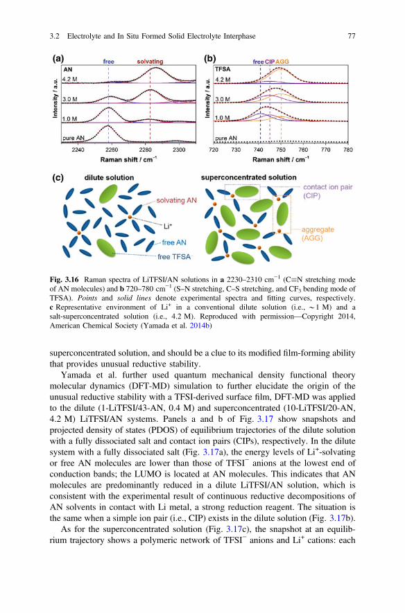
superconcentrated solution, and should be a clue to its modified film-forming abilitythat provides unusual reductive stability.
Yamada et al. further used quantum mechanical density functional theorymolecular dynamics (DFT-MD) simulation to further elucidate the origin of theunusual reductive stability with a TFSI-derived surface film, DFT-MD was appliedto the dilute (1-LiTFSI/43-AN, 0.4 M) and superconcentrated (10-LiTFSI/20-AN,4.2 M) LiTFSI/AN systems. Panels a and b of Fig. 3.17 show snapshots andprojected density of states (PDOS) of equilibrium trajectories of the dilute solutionwith a fully dissociated salt and contact ion pairs (CIPs), respectively. In the dilutesystem with a fully dissociated salt (Fig. 3.17a), the energy levels of Li+-solvatingor free AN molecules are lower than those of TFSI− anions at the lowest end ofconduction bands; the LUMO is located at AN molecules. This indicates that ANmolecules are predominantly reduced in a dilute LiTFSI/AN solution, which isconsistent with the experimental result of continuous reductive decompositions ofAN solvents in contact with Li metal, a strong reduction reagent. The situation isthe same when a simple ion pair (i.e., CIP) exists in the dilute solution (Fig. 3.17b).
As for the superconcentrated solution (Fig. 3.17c), the snapshot at an equilib-rium trajectory shows a polymeric network of TFSI− anions and Li+ cations: each
Fig. 3.16 Raman spectra of LiTFSI/AN solutions in a 2230–2310 cm−1 (C�N stretching modeof AN molecules) and b 720–780 cm−1 (S–N stretching, C–S stretching, and CF3 bending mode ofTFSA). Points and solid lines denote experimental spectra and fitting curves, respectively.c Representative environment of Li+ in a conventional dilute solution (i.e., *1 M) and asalt-superconcentrated solution (i.e., 4.2 M). Reproduced with permission—Copyright 2014,American Chemical Society (Yamada et al. 2014b)
3.2 Electrolyte and In Situ Formed Solid Electrolyte Interphase 77

TFSI− anion is interacting with multiple Li+ cations to form ion pairs, which isconsistent with the results of Raman analyses and totally different from those indilute solutions. In the PDOS profile (see bottom of Fig. 3.17c), TFSI− anionsprovide new unoccupied states at the lowest energy in the conduction bands and theenergy levels of TFSI− become lower than those of AN molecules; the LUMO islocated at TFSI− anions in the superconcentrated solution. The new unoccupiedstates are unique to such a superconcentrated solution with characteristic structuralfeatures of mutually networking TFSI− anions and Li+ cations with a small amountof solvents. The localized LUMOs at the TFSI− anions suggest that TFSI− anions,rather than AN solvents, are predominantly reduced to form a TFSI-derived surfacefilm on a graphite electrode in the superconcentrated electrolyte. These quantummechanical simulations with a realistic experimental salt concentration elucidate thepeculiar frontier orbital characters in a salt-superconcentrated solution and accountfor the formation of a TFSI-derived surface film, which is the origin of the enhancedreductive stability that allows for reversible lithium intercalation into a graphitenegative electrode.
With the successful use of highly concentrated electrolyte to enhance the sta-bility of the electrolyte toward graphite electrode in the absence of EC, the idea ofconcentrated electrolyte has been used to enhance the stability of Li metal anodes
Fig. 3.17 Supercells used and PDOS obtained in quantum mechanical DFT-MD simulations ona and b dilute (1-LiTFSI/43-AN corresponding to 0.4 M) and c superconcentrated(10-LiTFSI/20-AN corresponding to 4.2 M) LiTFSI/AN solutions. The illustrated structures arethe snapshots in equilibrium trajectories. For a dilute solution, both situations of LiTFSI salt [i.e.,a full dissociation and b CIP] were considered. Atom color: Li purple; C dark gray; H light gray;O red; N blue; S yellow; F green. Li atoms are highlighted in size. Insets in the PDOS profiles aremagnified figures of the lowest energy-level edge of the conduction band. Reproduced withpermission—Copyright 2014, American Chemical Society (Yamada et al. 2014b)
78 3 High Coulombic Efficiency of Lithium Plating/Stripping …
recently. Tobishima et al. (1984) studied the influence of salt concentration forLiClO4-PC/DME electrolytes up to a concentration of 3 M. The Li cycling CEplateaued at a high value of 92–93 % for 1 M and 2 M electrolytes, but decreasedto 87 % for a 3 M concentration. Suo et al. (2013) reported that the use ofLiTFSI-DME electrolytes up to a concentration of 7 M gave very promising Li-Scell performance due, in part, to the suppression of Li dendrite formation. These“solvent-in-salt” electrolytes exhibit a high Li+-ion transference number (0.73), inwhich salt holds a dominant position in the Li+-ion transport system. It remarkablyenhances the cyclic and safety performance of next-generation high-energyrechargeable Li batteries via an effective suppression of Li dendrite growth andshape change in the Li metal anode. Moreover, when used in a Li-S battery, theadvantage of this electrolyte is further demonstrated in that lithium polysulfidedissolution is inhibited, thus overcoming one of today’s most challenging techno-logical hurdles, the “polysulfide shuttle phenomenon.” Consequently, a CE nearing100 % and long cycling stability are achieved.
Recently, Qian et al., found that replacing LiTFSI with LiFSI can greatlyincrease the stability of Li metal. The use of highly concentrated electrolytescomposed of DME solvents and the LiFSI salt enables the high-rate cycling of a Limetal anode at high CE (up to 99.1 %) without dendrite growth. With 4 M LiFSI inDME as the electrolyte, a Li||Li cell can be cycled at high rate (10 mA cm−2) formore than 6000 cycles with no increase in the cell impedance, and a Li||Cu cell canbe cycled at 4 mA cm−2 for more than 1000 cycles with an average CE of 98.4 %,as shown in (Fig. 3.18). These excellent high-rate performances can be attributed tothe increased solvent coordination and increased availability of Li+ concentration inthe electrolyte. The small amount of degradation that occurred during each cycle ledto the slow buildup of a black interphasial layer, but this did not lead to a change inthe polarization for the plating/stripping, suggesting that this layer did not impedethe cycling to any significant extent. Further development of this electrolyte maylead to practical applications for Li metal anodes in rechargeable batteries. Thefundamental mechanisms behind the high-rate ion exchange and stability of theelectrolytes also shed light on the stability of other electrochemical systems.
3.2.6 Self-healing Electrostatic Shield Mechanism
As we discussed in the previous sections, various approaches have been used tosuppress Li dendrite formation and growth. However, most of these approaches relyon the formation of a strong layer to mechanically block the Li dendrite growth.Recently, Ding et al. developed a novel mechanism that could influence Li depo-sition preference to obtain a dendrite-free Li anode, which is called the self-healingelectrostatic shield (SHES) mechanism (Ding et al. 2013b). This mechanism doesnot rely on the mechanical strength of a protection layer. Instead, it relies on anelectrostatic shield formed by electrolyte additives. This layer is positively chargedand floating on the tip area of potential dendrites on the surface of deposited Li film,
3.2 Electrolyte and In Situ Formed Solid Electrolyte Interphase 79

but does not physically attach to the dendrite and Li film. During the Li depositionprocess, this electrostatic shield will repel the incoming Li+ ions and force them tobe deposited in the valley area instead of peak area of the Li film. Once appliedelectric voltage is turned off, this charged cloud will dissipate and does not form apermanent film on the Li surface.
Figure 3.19 illustrates the SHES mechanism to prevent Li dendrite formation.According to the Nernst equation, it is possible to find certain metal cations (M+)that have an effective reduction potential lower than that of Li+ if the M+ has astandard redox potential close to those of Li+ and a chemical activity much lowerthan that of Li+ (Ding et al. 2013b). For example, cesium ion (Cs+) at a lowconcentration of 0.01 M has an effective reduction potential of −3.144 V, which islower than that of Li+ at 1.0 M concentration (−3.040 V). As a result, in a mixedelectrolyte where the additive Cs+ concentration is much lower than the Li+
Fig. 3.18 Electrochemical performance of Li metal plating/stripping on a Cu working electrode:voltage profiles for the cell cycled in a 1 M LiFSI-DME and b 4 M LiFSI-DME, c polarization ofthe plating/stripping for the 4 M LiFSI-DME electrolyte with different current densities and d CEof Li deposition/striping in 4 M LiFSI-DME at different current densities: voltage profiles for thecell cycled in a 1 M LiFSI-DME and b 4 M LiFSI-DME, c polarization of the plating/stripping forthe 4 M LiFSI-DME electrolyte with different current densities, and d CE of Li deposition/stripingin 4 M LiFSI-DME at different current densities. Reproduced with permission—Copyright 2015,Macmillan Publishers Limited (Qian et al. 2015b)
80 3 High Coulombic Efficiency of Lithium Plating/Stripping …
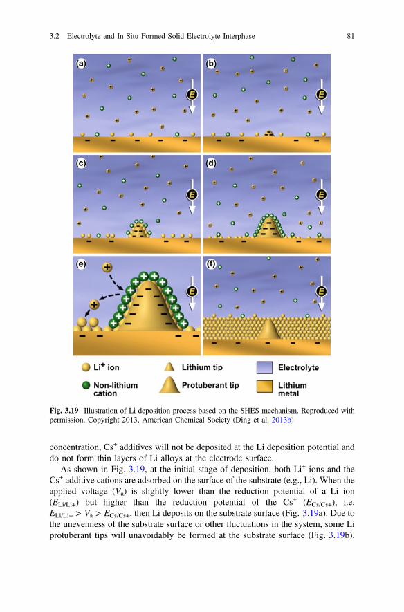
concentration, Cs+ additives will not be deposited at the Li deposition potential anddo not form thin layers of Li alloys at the electrode surface.
As shown in Fig. 3.19, at the initial stage of deposition, both Li+ ions and theCs+ additive cations are adsorbed on the surface of the substrate (e.g., Li). When theapplied voltage (Va) is slightly lower than the reduction potential of a Li ion(ELi/Li+) but higher than the reduction potential of the Cs+ (ECs/Cs+), i.e.ELi/Li+ > Va > ECs/Cs+, then Li deposits on the substrate surface (Fig. 3.19a). Due tothe unevenness of the substrate surface or other fluctuations in the system, some Liprotuberant tips will unavoidably be formed at the substrate surface (Fig. 3.19b).
Fig. 3.19 Illustration of Li deposition process based on the SHES mechanism. Reproduced withpermission. Copyright 2013, American Chemical Society (Ding et al. 2013b)
3.2 Electrolyte and In Situ Formed Solid Electrolyte Interphase 81

Then a higher electron-charge density appears at the newly formed Li protuberancethat attracts more Li ions from the electrolyte and deposits more on the tip than onother sites, thus forming the Li dendrite as would happen in the conventionalelectrolyte. However, in the SHES mechanism, more non-Li Cs+ cations will alsobe adsorbed on the tip by electrostatic attraction force at the same time (Fig. 3.19c).When the adsorbed Li ions deposit on this tip continuously, the number of Li ionsaround the tip decreases significantly but more and more non-Li cations that do notelectrochemically reduce at this potential will accumulate and surround the tipsurface. Then a positively charged electrostatic shield is automatically formed byadsorbed non-Li cations on the Li tip (Fig. 3.19d). Due to the charge repelling andsteric hindrance effect of the non-Li cation shield, it is more difficult for Li ions toadsorb and deposit on such a tip. Li ions have to deposit at other sites with lowernon-Li cation adsorption ratios. As a result, the continuous Li growth on this tip(dendrite root) is stopped. It is reasonable to believe that there should be a lot of tipsforming on the Li surface, but no tips would grow exceptionally as shown inFig. 3.19e. Eventually, a smooth Li surface could be formed as illustrated inFig. 3.19f; then this self-healing process will repeat itself. In fact, Fig. 3.19 is asimplified illustration of a Li deposition process with SHES additives. In practice,an SEI layer will always form on the surface of Li metal once it is in contact withelectrolyte. Therefore, Cs+ ions will accumulate on the outside of the SEI layer andquickly form an electrostatic shield and prevent amplification of Li dendrite growth.
The SHES additive approach is different from those of inorganic additives (in-cluding Mg2+, Al3+, Zn2+, Ga3+, In3+, and Sn2+) used in previous studies (Matsudaet al. 1991); (Matsuda 1993). These additive metal ions are consumed during eachLi deposition and their effectiveness will soon fade with increasing cycles.However, in the proposed SHES mechanism, the additive cations will not beconsumed and can last for long-term cycling. This prediction has been verified bychemical analysis of the deposited films.
Figure 3.20 shows SEM images of the deposited Li films on copper substrateswith different Cs+ concentrations. In the control electrolyte without the CsPF6additive, Li dendrite formation is clearly observed in the deposited Li film (seeFig. 3.20a). Even at very low Cs+ concentrations (0.005 M), Li dendrite formationis significantly decreased (Fig. 3.20b). When the Cs+ concentration is increased to0.05 M, the dendrite formation is completely eliminated, resulting in a very distinctimprovement (Fig. 3.20c). Further investigation indicated that even if a dendritic Lifilm was initially formed during Li deposition, it could be smoothened if furtherdeposition was conducted in the electrolyte containing Cs+ additive. In addition toCs+, Rb+ also exhibits a lower effective reduction potential when its concentration ismuch lower than that of Li+. Not surprisingly, RbPF6 was also able to suppress Lidendrite growth although it is not as effective as CsPF6. Unlike other cations,reported in the previous work, that will form part of the SEI layer (Matsuda et al.1991) (Matsuda 1993), SHES additives (Cs+, Rb+, etc.) do not form part of the SEIlayer as verified by several trace analysis techniques (Ding et al. 2013b).
82 3 High Coulombic Efficiency of Lithium Plating/Stripping …
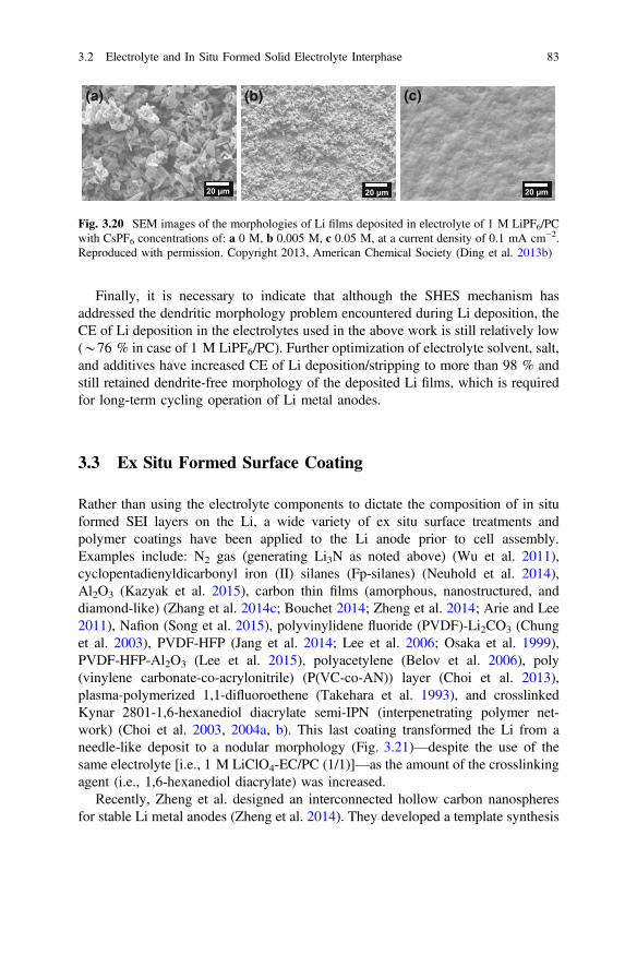
Finally, it is necessary to indicate that although the SHES mechanism hasaddressed the dendritic morphology problem encountered during Li deposition, theCE of Li deposition in the electrolytes used in the above work is still relatively low(*76 % in case of 1 M LiPF6/PC). Further optimization of electrolyte solvent, salt,and additives have increased CE of Li deposition/stripping to more than 98 % andstill retained dendrite-free morphology of the deposited Li films, which is requiredfor long-term cycling operation of Li metal anodes.
3.3 Ex Situ Formed Surface Coating
Rather than using the electrolyte components to dictate the composition of in situformed SEI layers on the Li, a wide variety of ex situ surface treatments andpolymer coatings have been applied to the Li anode prior to cell assembly.Examples include: N2 gas (generating Li3N as noted above) (Wu et al. 2011),cyclopentadienyldicarbonyl iron (II) silanes (Fp-silanes) (Neuhold et al. 2014),Al2O3 (Kazyak et al. 2015), carbon thin films (amorphous, nanostructured, anddiamond-like) (Zhang et al. 2014c; Bouchet 2014; Zheng et al. 2014; Arie and Lee2011), Nafion (Song et al. 2015), polyvinylidene fluoride (PVDF)-Li2CO3 (Chunget al. 2003), PVDF-HFP (Jang et al. 2014; Lee et al. 2006; Osaka et al. 1999),PVDF-HFP-Al2O3 (Lee et al. 2015), polyacetylene (Belov et al. 2006), poly(vinylene carbonate-co-acrylonitrile) (P(VC-co-AN)) layer (Choi et al. 2013),plasma-polymerized 1,1-difluoroethene (Takehara et al. 1993), and crosslinkedKynar 2801-1,6-hexanediol diacrylate semi-IPN (interpenetrating polymer net-work) (Choi et al. 2003, 2004a, b). This last coating transformed the Li from aneedle-like deposit to a nodular morphology (Fig. 3.21)—despite the use of thesame electrolyte [i.e., 1 M LiClO4-EC/PC (1/1)]—as the amount of the crosslinkingagent (i.e., 1,6-hexanediol diacrylate) was increased.
Recently, Zheng et al. designed an interconnected hollow carbon nanospheresfor stable Li metal anodes (Zheng et al. 2014). They developed a template synthesis
20 μm
(a) (b) (c)
20 μm 20 μm
Fig. 3.20 SEM images of the morphologies of Li films deposited in electrolyte of 1 M LiPF6/PCwith CsPF6 concentrations of: a 0 M, b 0.005 M, c 0.05 M, at a current density of 0.1 mA cm−2.Reproduced with permission. Copyright 2013, American Chemical Society (Ding et al. 2013b)
3.2 Electrolyte and In Situ Formed Solid Electrolyte Interphase 83

method for fabricating the hollow carbon nanopheres, using vertical deposition ofpolystyrene nanoparticles (Fig. 3.22a). A colloidal multilayer opal structure isformed on Cu foil by slowly evaporating a 4 % aqueous solution of carboxylatedpolystyrene particles. The highly monodisperse polystyrene nanoparticles form aclose-packed thin film with long range order (Fig. 3.22b). The polystyrenenanoparticles are coated with a thin film of amorphous carbon usingflash-evaporation of carbon fibers (Fig. 3.22c). The samples are then heated in atube furnace to 400 °C under an inert atmosphere, forming hollow carbon nano-pheres on the Cu substrate (Fig. 3.22e). TEM characterization shows that the car-bon wall has a thickness of � 20 nm (Fig. 3.22f). The hemispherical carbonnanospheres are interconnected to form a thin film, which can be peeled off the Cusurface easily. Mechanical flexibility is important in accommodating the volumetric
Fig. 3.21 SEM images of Li deposited from a 1 M LiClO4-EC/PC (1/1) electrolyte a without asurface coating, b with a protective coating of only Kynar 2801 and with semi-IPN surfacecoatings with Kynar 2801/1,6-hexanediol diacrylate ratios: c (7/3), d (5/5) and e (3/7). Reproducedwith permission—Copyright 2004, Elsevier (Choi et al. 2004b)
84 3 High Coulombic Efficiency of Lithium Plating/Stripping …
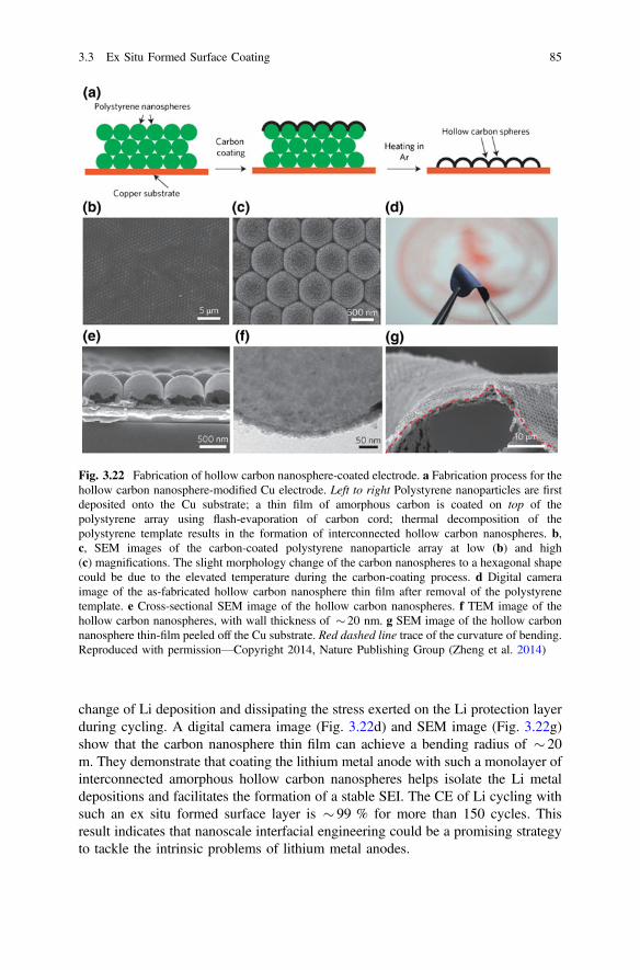
change of Li deposition and dissipating the stress exerted on the Li protection layerduring cycling. A digital camera image (Fig. 3.22d) and SEM image (Fig. 3.22g)show that the carbon nanosphere thin film can achieve a bending radius of � 20m. They demonstrate that coating the lithium metal anode with such a monolayer ofinterconnected amorphous hollow carbon nanospheres helps isolate the Li metaldepositions and facilitates the formation of a stable SEI. The CE of Li cycling withsuch an ex situ formed surface layer is � 99 % for more than 150 cycles. Thisresult indicates that nanoscale interfacial engineering could be a promising strategyto tackle the intrinsic problems of lithium metal anodes.
Fig. 3.22 Fabrication of hollow carbon nanosphere-coated electrode. a Fabrication process for thehollow carbon nanosphere-modified Cu electrode. Left to right Polystyrene nanoparticles are firstdeposited onto the Cu substrate; a thin film of amorphous carbon is coated on top of thepolystyrene array using flash-evaporation of carbon cord; thermal decomposition of thepolystyrene template results in the formation of interconnected hollow carbon nanospheres. b,c, SEM images of the carbon-coated polystyrene nanoparticle array at low (b) and high(c) magnifications. The slight morphology change of the carbon nanospheres to a hexagonal shapecould be due to the elevated temperature during the carbon-coating process. d Digital cameraimage of the as-fabricated hollow carbon nanosphere thin film after removal of the polystyrenetemplate. e Cross-sectional SEM image of the hollow carbon nanospheres. f TEM image of thehollow carbon nanospheres, with wall thickness of � 20 nm. g SEM image of the hollow carbonnanosphere thin-film peeled off the Cu substrate. Red dashed line trace of the curvature of bending.Reproduced with permission—Copyright 2014, Nature Publishing Group (Zheng et al. 2014)
3.3 Ex Situ Formed Surface Coating 85

3.4 Mechanical Blocking and Solid Electrolytes
Commercial separators for Li-ion batteries tend to be thin (<30 µm), microporouspolyolefin membranes made from polyethylene (PE), polypropylene, or laminatesof PE/polypropylene (Arora and Zhang 2004). Such separators are frequently alsoused when testing cells with Li anodes. It has been proposed, however, that dendriteformation can be inhibited by incorporating a solid separator/electrolyte, especiallyone with an acceptable ionic conductivity and a high shear modulus of approxi-mately twice that of Li (i.e., 9 GPa) (Monroe and Newman 2005; Ferrese andNewman 2014).
3.4.1 Solid Polymer Electrolytes
Early work with solid polymer electrolytes (SPEs) and Li metal anodes focused onLi salt-PEO salt and related electrolytes (Gauthier et al. 1985b; Xue et al. 2015).The relatively low conductivity of such electrolytes and their tendency to crystallizegenerally required the cells to be plasticized via the inclusion of a liquid electrolyteor instead operated at elevated temperature (e.g., 75–90 °C) (Appetecchi et al.1998). Using a polyether copolymer with an added 1–3 M LiClO4-EC/PC (1/1)electrolyte, Matsui and Takeyama used a visual study of the Li-plasticized polymerelectrolyte interface to examine the effects of the electrolyte composition on the Lideposition morphology (Matsui and Takeyama 1995). The solid electrolytes thatmost effectively suppressed Li dendrites were those with a lower liquid electrolytecontent (� 70 %) and that were stiff and elastic (e.g., with a molecular weight >16,000 before crosslinking).Unplasticized polyether electrolytes are generally found to exhibit a low Li/SPE
interfacial resistance that remains relatively stable over time, even upon storage atelevated temperature (Appetecchi et al. 1998; Appetecchi and Passerini 2002;Fauteux 1993). Importantly, upon discharging the Li anode, the passivation layerformed at this interface is disrupted as indicated by the Li plating/stripping over-voltage dropping to a low value (Appetecchi and Passerini 2002). The ionicresistance of this layer, however, increased substantially with decreasing temper-ature (� 65 °C) due to the crystallization of some of the PEO (Tm * 65 °C)(Appetecchi and Passerini 2002). This prevents self-discharge and other parasiticreactions during prolonged storage at ambient temperature, while the rapid dis-ruption of the layer after a few initial cycles at elevated temperature enables thecells to perform well even after prolonged storage periods. The cell assemblyprocedure (including hot lamination) used for the Li/SPE interface was found to becritical for determining the stability of the interface over time (Appetecchi et al.2000). In situ attenuated total reflectance FTIR measurements have indicated that
86 3 High Coulombic Efficiency of Lithium Plating/Stripping …

electrodeposited Li reacts with the PEO in a LiClO4-PEO electrolyte to formalkoxides (ROLi) (Ichino et al. 1991), similar to the reaction of Li with glymes(Aurbach and Granot 1997) and THF:
��CH2OCH2��þLi ! ��CH2OLiþ other products
After an initial fast reaction period, further reaction with polyethers is relativelyslow (Lisowska-Oleksiak 1999). For SPEs containing LiBETI, the interfacialresistance was found to proportionally depend upon the salt concentration (at opencircuit) (Appetecchi and Passerini 2002). This indicates that the salt may have a keyrole in the electrode passivation (either by reacting directly with the Li metal orinfluencing the reaction of the PEO with the Li). Evaluations of Li surfaces exposedto polyether network polymers (NPs) containing either LiTFSI or LiBF4 indicatedthat the Li-polymer electrolyte interfacial resistance decreased and then becamerelatively stable for the electrolyte with LiTFSI, but the resistance grew continu-ously and became very large for the LiBF4-containing electrolyte (Ismail et al.2001). XPS indicated that the SEI layers formed in the LiTFSI electrolyte wererelatively thin with TFSI− components present at the solution interface (either dueto adsorbed or degraded anions), while the layers formed with the LiBF4 electrolytewere thicker and contained much more LiF (Fig. 3.23) (Ismail et al. 2001). Theseresults are analogous to what is obtained for liquid ether electrolytes in which thehigh stability of the ether solvent results in SEI compositions that are governed bythe anion reactions.
Contrary to what was initially believed, Li dendrites do form in polymer elec-trolytes (Fig. 3.24a–c) (Brissot et al. 1998, 1999c, d; Dollé et al. 2002; Liu et al.2010a, b, 2011b; Wang et al. 2012). To improve the ionic conductivity and restrict
Fig. 3.23 Schematicillustration of the surface filmformed on Li foil after contactwith a LiTFSI-NP andb LiBF4-NP polymerelectrolytes. Reproduced withpermission—Copyright 2001,Elsevier (Ismail et al. 2001)
3.4 Mechanical Blocking and Solid Electrolytes 87

Li dendrite growth in polymer electrolytes, the polymers have been crosslinked(Khurana et al. 2014; Ueno et al. 2011), inorganic particle fillers have been added(Appetecchi et al. 1998, 1999; Zhang et al. 2002; Liu et al. 2010a; Kim et al. 2013c)and ILs have been incorporated (Shin et al. 2003, 2005a, b, 2006; Cheng et al.2007; Choi et al. 2007b, 2011; Kim et al. 2007a, 2010a Zhu et al. 2008; Appetecchiet al. 2010, 2011; Balducci et al. 2011; Yun et al. 2011; Kim et al. 2012; Wanget al. 2012; Wetjen et al. 2013; Swiderska-Mocek and Naparstek 2014; de Vrieset al. 2015). Li cycling CE values >95 % were reported for cells with SPEs withand without fillers, and the cells could be cycled for many hundreds of cycles atelevated temperature (e.g., 90 °C) (Appetecchi et al. 1998, 1999, 2000; Appetecchiand Passerini 2002; Gauthier et al. 1985a). The addition of ILs to SPEs enabled theoperating temperature to be lowered to 30–40 °C and reduced the tendency for Lidendrites to form and penetrate the SPE (Fig. 3.24d–i) (Shin et al. 2003, 2005b; Liuet al. 2010b). The inclusion of both an inorganic filler and IL did enable repeated Liplating/stripping cycles without dendrite formation (Liu et al. 2011b).
Fig. 3.24 Optical images of Li dendrite growth at a current density of 0.5 mA cm−2 at 60 °C.First column Li|LiTFSI-P(EO)18|Li cell at times of a 0, b 15, and c 20 h second and third columnLi|P(EO)18-LiTFSI-1.44PI13TFSI|Li cell at times of d 0, e 30, f 35, g 45, h 65, and i 75 h.Reproduced with permission—Copyright 2010, The Electrochemical Society (Liu et al. 2010b)
88 3 High Coulombic Efficiency of Lithium Plating/Stripping …
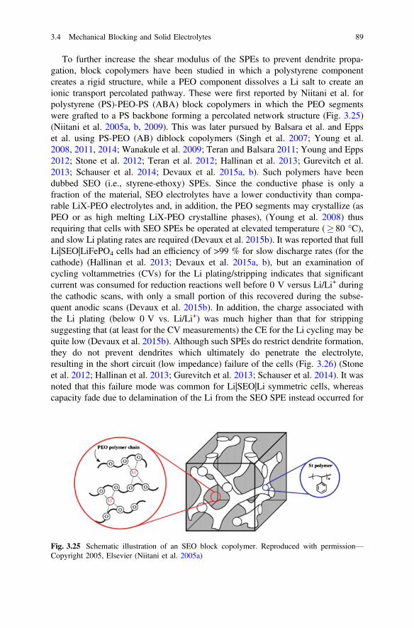
To further increase the shear modulus of the SPEs to prevent dendrite propa-gation, block copolymers have been studied in which a polystyrene componentcreates a rigid structure, while a PEO component dissolves a Li salt to create anionic transport percolated pathway. These were first reported by Niitani et al. forpolystyrene (PS)-PEO-PS (ABA) block copolymers in which the PEO segmentswere grafted to a PS backbone forming a percolated network structure (Fig. 3.25)(Niitani et al. 2005a, b, 2009). This was later pursued by Balsara et al. and Eppset al. using PS-PEO (AB) diblock copolymers (Singh et al. 2007; Young et al.2008, 2011, 2014; Wanakule et al. 2009; Teran and Balsara 2011; Young and Epps2012; Stone et al. 2012; Teran et al. 2012; Hallinan et al. 2013; Gurevitch et al.2013; Schauser et al. 2014; Devaux et al. 2015a, b). Such polymers have beendubbed SEO (i.e., styrene-ethoxy) SPEs. Since the conductive phase is only afraction of the material, SEO electrolytes have a lower conductivity than compa-rable LiX-PEO electrolytes and, in addition, the PEO segments may crystallize (asPEO or as high melting LiX-PEO crystalline phases), (Young et al. 2008) thusrequiring that cells with SEO SPEs be operated at elevated temperature (� 80 °C),and slow Li plating rates are required (Devaux et al. 2015b). It was reported that fullLi|SEO|LiFePO4 cells had an efficiency of >99 % for slow discharge rates (for thecathode) (Hallinan et al. 2013; Devaux et al. 2015a, b), but an examination ofcycling voltammetries (CVs) for the Li plating/stripping indicates that significantcurrent was consumed for reduction reactions well before 0 V versus Li/Li+ duringthe cathodic scans, with only a small portion of this recovered during the subse-quent anodic scans (Devaux et al. 2015b). In addition, the charge associated withthe Li plating (below 0 V vs. Li/Li+) was much higher than that for strippingsuggesting that (at least for the CV measurements) the CE for the Li cycling may bequite low (Devaux et al. 2015b). Although such SPEs do restrict dendrite formation,they do not prevent dendrites which ultimately do penetrate the electrolyte,resulting in the short circuit (low impedance) failure of the cells (Fig. 3.26) (Stoneet al. 2012; Hallinan et al. 2013; Gurevitch et al. 2013; Schauser et al. 2014). It wasnoted that this failure mode was common for Li|SEO|Li symmetric cells, whereascapacity fade due to delamination of the Li from the SEO SPE instead occurred for
Fig. 3.25 Schematic illustration of an SEO block copolymer. Reproduced with permission—Copyright 2005, Elsevier (Niitani et al. 2005a)
3.4 Mechanical Blocking and Solid Electrolytes 89
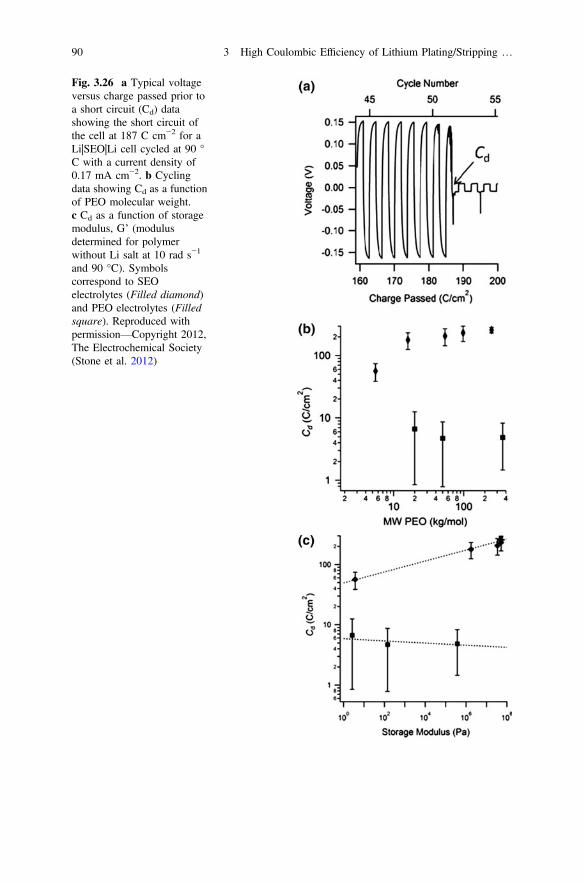
Fig. 3.26 a Typical voltageversus charge passed prior toa short circuit (Cd) datashowing the short circuit ofthe cell at 187 C cm−2 for aLi|SEO|Li cell cycled at 90 °C with a current density of0.17 mA cm−2. b Cyclingdata showing Cd as a functionof PEO molecular weight.c Cd as a function of storagemodulus, G’ (modulusdetermined for polymerwithout Li salt at 10 rad s−1
and 90 °C). Symbolscorrespond to SEOelectrolytes (Filled diamond)and PEO electrolytes (Filledsquare). Reproduced withpermission—Copyright 2012,The Electrochemical Society(Stone et al. 2012)
90 3 High Coulombic Efficiency of Lithium Plating/Stripping …

Li|SEO|LiFePO4 cells (Devaux et al. 2015a). One possible explanation for this isthat when the latter cells are cycled, the plating of the Li will result in an expansionof the cell (since the volume increase for the plated Li is significantly larger than thevolume decrease for the cathode delithiation). Discharge of the cell then results in acontraction. The repetition of this expansion/contraction during cycling likelyresults in the delamination, since the SEO SPE is rigid. In contrast, when Li issimply shuttled from one Li electrode to another (i.e., symmetric cell), the cellvolume should remain approximately constant during cycling and Li dendrites willextend into the electrolyte from both electrodes through defects in the rigid SPE.Since high modulus (i.e., rigid) block copolymer electrolytes have been unsuc-cessful at fully preventing dendrites from penetrating across the electrolyte to formshort circuits, solid electrolytes with an even higher modulus, such as inorganic(crystalline or glassy) electrolytes, have been developed for batteries with Lianodes.
3.4.2 Solid Inorganic Electrolytes
Inorganic SSEs composed of inorganic compounds are nonflammable and generallymore electrochemically stable (Jung et al. 2015; Takada 2013; Fergus 2010; Renet al. 2015b). Therefore, they have been regarded as the ideal materials to protect Limetal anodes against dendrite penetration because of their unity Li+ transfer number(tLi+) and high mechanical strength, which often far exceeds that of Li itself. Boththin films and bulk forms of solid-state Li-ion conductors have been developed toeffectively block Li dendrite growth (Christensen et al. 2012; Shao et al. 2012b). Todate, the most widely used inorganic thin-film ion conductor is nitrogen-dopedLi-ion phosphate film (LiPON) developed by Bates and Dudney et al. in the early1990s (Bates et al. 1993). LiPON exhibits a conductivity of 2 � 10−6 S cm−1 at25 °C and excellent long-term stability in contact with Li metal. Bates and Dudneyalso first reported the application of LiPON as a Li-ion-conducting electrolyte andLi metal protection layer in a thin-film battery (Bates 1994). Later on, Herbert et al.(2011) reported that the shear modulus of LiPON is approximately 77 GPa, 7.3times higher than that of Li, which far exceeds the basic requirement of mechanicalstrength for electrolyte to suppress the Li dendrites, about twice that of Li. Thisresult is also independent of the substrate type, film thickness, and annealing;therefore, LiPON is expected to be fully capable of mechanically suppressingdendrite formation at the Li/LiPON interface in thin-film batteries.
The typical structure of thin-film, solid-state batteries using LiPON as ionconductor is Li|LiPON|LiCoO2 (Bates et al. 1993). The long cycle and shelf lives ofthese batteries result from the properties of the glassy LiPON electrolyte, which isstable in contact with metallic Li at potentials from zero to nearly 5.5 V and hasacceptable conductance in the thin-film form. These batteries have demonstrated avery long shelf life. For example, Dudney (2005) demonstrated that test cells havemaintained a charged state for more than a year with negligible loss of capacity
3.4 Mechanical Blocking and Solid Electrolytes 91

(see Fig. 3.27a. This level of reliability is not possible for other types ofrechargeable batteries. These batteries also exhibit very high specific energies(Wh/kg) and specific power, as shown in Fig. 3.27b when only the active materialsare considered. The effect of substrate and package material on the specific energyand energy density of the batteries will be discussed later. The cycle life of thesebatteries can exceed more than 40,000 full depth charge–discharge cycles, whichfar exceeds the cycle lives for other types of batteries. There is no liquid electrolyte,no polymer, or any other organic material present in thin-film, solid-state batteries;therefore, side reactions between electrode and electrolyte are minimized.
Many different bulk-form ceramic glass (*50–200 lm thick) Li-ion conductorshave also been developed and can effectively suppress Li dendrite growth. Oneexample of these glass electrolytes is LiSICON-type Li1+xAlxTi2−x(PO4)3 (LATP)developed by Fu (1997a, b). Recently, Wang et al. reported a Li||LiMn2O4 batteryoperated in aqueous electrolyte using a Li metal anode protected by LATP glass.The battery demonstrates excellent stability and good electrochemical performance(Wang et al. 2013c). LATP glass prepared by Ohara glass and other companies hasbeen widely used by many research groups worldwide to protect Li metal glass andhas been applied in Li-air and Li-S batteries, as well as other energy storage andconversion systems. LATP glass is stable in weak acid and alkaline electrolyte. Oneof the disadvantages of LATP glass is that it is not stable when in contact with Limetal. Visco et al. first solved this problem by introducing an interfacial layer (asolid layer such as Cu3N, LiPON, or nonaqueous electrolyte) between the Li metaland the Ohara glass, thus forming a protected Li electrode (PLE) (Visco et al.2004a, 2009). Figure 3.28 shows the schematic of a PLE proposed by Visco et al.(2009), where the Li electrode was protected by an interfacial layer and a Li metalphosphate glass. Figure 3.26b shows a Li-air battery with a double-sided PLE.Li-air batteries using this PLE can operate in both aqueous and nonaqueous elec-trolytes (Zhang et al. 2010b; Yoo and Zhou 2011; Li et al. 2012a, b). However,
Fig. 3.27 a Capacities recorded for three Li||LiCoO2 thin-film batteries when rapidly dischargedafter prolonged storage in the fully charged state. b Power and energy density determined fromconstant-current discharge measurements for thin-film batteries with a Li anode and the indicatedthin-film cathode. The batteries were discharged over 4.2–3.0, 4.5–3.0, and 4.5–2.5 V for thecLiCoO2, cLiMn2O4, and nLixMn2−yO4 cathodes, respectively (Filled square). Reproduced withpermission—Copyright 2005, Elsevier (Dudney 2005)
92 3 High Coulombic Efficiency of Lithium Plating/Stripping …
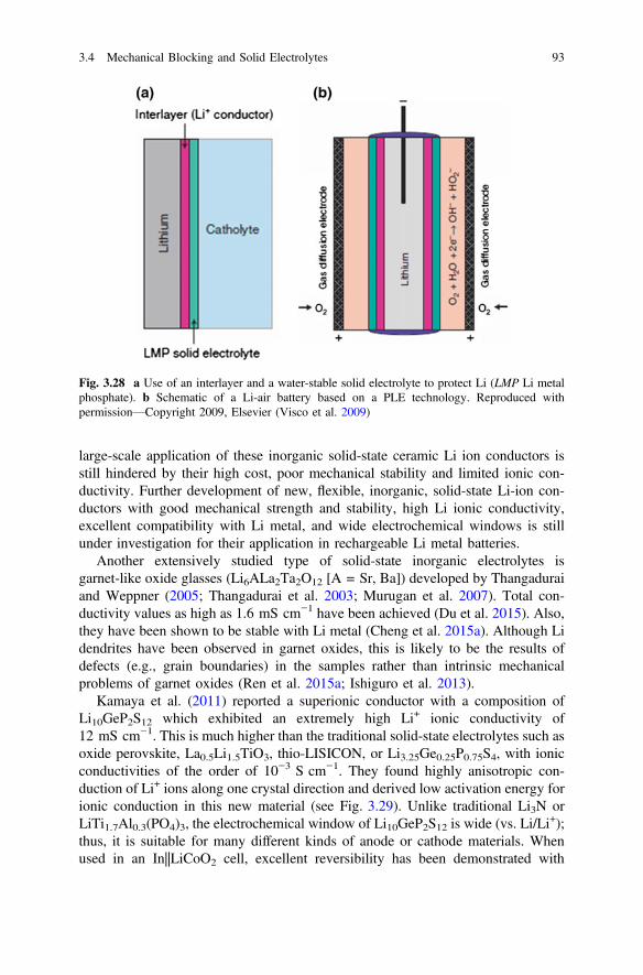
large-scale application of these inorganic solid-state ceramic Li ion conductors isstill hindered by their high cost, poor mechanical stability and limited ionic con-ductivity. Further development of new, flexible, inorganic, solid-state Li-ion con-ductors with good mechanical strength and stability, high Li ionic conductivity,excellent compatibility with Li metal, and wide electrochemical windows is stillunder investigation for their application in rechargeable Li metal batteries.
Another extensively studied type of solid-state inorganic electrolytes isgarnet-like oxide glasses (Li6ALa2Ta2O12 [A = Sr, Ba]) developed by Thangaduraiand Weppner (2005; Thangadurai et al. 2003; Murugan et al. 2007). Total con-ductivity values as high as 1.6 mS cm−1 have been achieved (Du et al. 2015). Also,they have been shown to be stable with Li metal (Cheng et al. 2015a). Although Lidendrites have been observed in garnet oxides, this is likely to be the results ofdefects (e.g., grain boundaries) in the samples rather than intrinsic mechanicalproblems of garnet oxides (Ren et al. 2015a; Ishiguro et al. 2013).
Kamaya et al. (2011) reported a superionic conductor with a composition ofLi10GeP2S12 which exhibited an extremely high Li+ ionic conductivity of12 mS cm−1. This is much higher than the traditional solid-state electrolytes such asoxide perovskite, La0.5Li1.5TiO3, thio-LISICON, or Li3.25Ge0.25P0.75S4, with ionicconductivities of the order of 10−3 S cm−1. They found highly anisotropic con-duction of Li+ ions along one crystal direction and derived low activation energy forionic conduction in this new material (see Fig. 3.29). Unlike traditional Li3N orLiTi1.7Al0.3(PO4)3, the electrochemical window of Li10GeP2S12 is wide (vs. Li/Li
+);thus, it is suitable for many different kinds of anode or cathode materials. Whenused in an In||LiCoO2 cell, excellent reversibility has been demonstrated with
Fig. 3.28 a Use of an interlayer and a water-stable solid electrolyte to protect Li (LMP Li metalphosphate). b Schematic of a Li-air battery based on a PLE technology. Reproduced withpermission—Copyright 2009, Elsevier (Visco et al. 2009)
3.4 Mechanical Blocking and Solid Electrolytes 93

operation voltage at 3.3 V. One disadvantage of Li10GeP2S12, as well as most ofsulfur-based Li ionic conductors, is that they are highly sensitive to moisture andunstable when in contact with Li metal. Therefore, they cannot be used in directcontact with Li anodes and their processing requires a very low humidity envi-ronment. Since they are even more sensitive to moisture than Li metal itself, so theyoften need to be processed in an Ar-filled glove box rather than in a dry room,which is suitable to handle Li metal.
Although solid, inorganic electrolytes have many advantages, including sup-pressing dendrite, stability with Li anodes, reducing battery capacity losses fromcycling (i.e., a longer cycle life), usability at elevated temperature, improved safety,and high reliability, while other promoted features include the simplicity of celldesign, an absence of leakage, a better resistance to shocks/vibrations andaggressive environments, and superior electrochemical, mechanical, and thermalstability; (Fergus 2010; Cao et al. 2014; Wang et al. 2015c; Knauth 2009), seldomdoes a solid-state electrolyte exhibits all these advantages at the same time.Therefore, the practical applications of the solid-state electrolyte are often limited tothin films and associated with other limiting factors.
In thin-film solid-state batteries, the glass electrolyte is used only to separate theanode and cathode. The energy density of solid-state batteries is still very limitedbecause the thickness of electrode is limited by its own ionic and electronic con-ductivity. Through improvements in the ionic conductivity and stability of SSEs,these electrolytes also may be used as an ionic conductor inside thick electrodelayers. Some SSEs have been used with limited success to prepare solid-statebatteries (Nishio et al. 2009). In addition to good ionic conductivity of the elec-trolyte itself, several other conditions need to be optimized for practical applications
Fig. 3.29 All-solid-state electrolyte reported by Kamaya et al. Li+ ions transport quickly throughpartially occupied LiS4 tetrahedra in the Li10GeP2S12 lattice and interstitial positions that areconnected by a common edge. Reproduced with permission—Copyright 2011, MacmillanPublishers Limited (Kamaya et al. 2011)
94 3 High Coulombic Efficiency of Lithium Plating/Stripping …
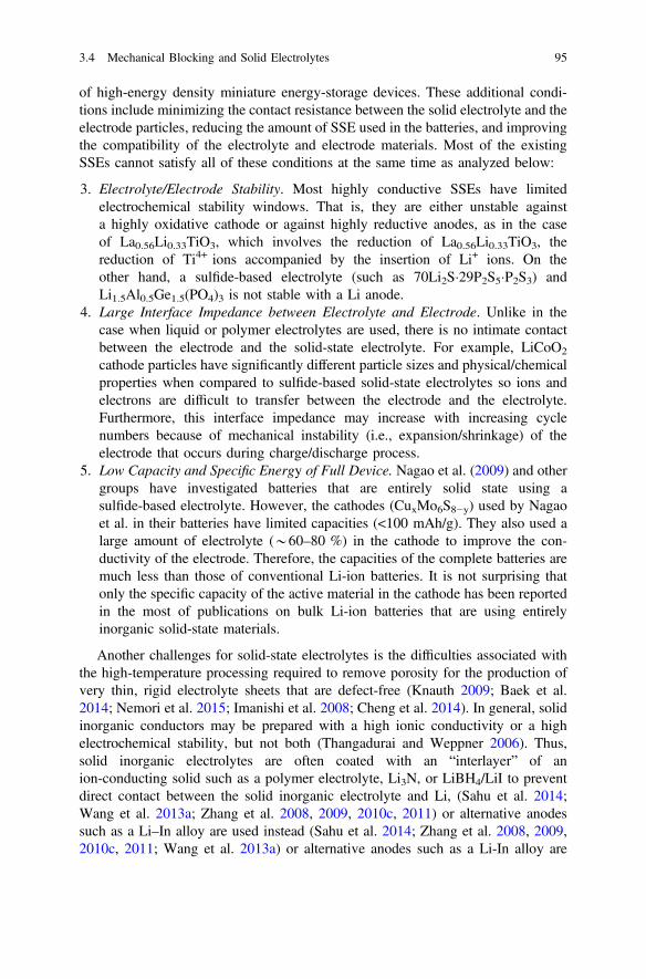
of high-energy density miniature energy-storage devices. These additional condi-tions include minimizing the contact resistance between the solid electrolyte and theelectrode particles, reducing the amount of SSE used in the batteries, and improvingthe compatibility of the electrolyte and electrode materials. Most of the existingSSEs cannot satisfy all of these conditions at the same time as analyzed below:
3. Electrolyte/Electrode Stability. Most highly conductive SSEs have limitedelectrochemical stability windows. That is, they are either unstable againsta highly oxidative cathode or against highly reductive anodes, as in the caseof La0.56Li0.33TiO3, which involves the reduction of La0.56Li0.33TiO3, thereduction of Ti4+ ions accompanied by the insertion of Li+ ions. On theother hand, a sulfide-based electrolyte (such as 70Li2S29P2S5P2S3) andLi1.5Al0.5Ge1.5(PO4)3 is not stable with a Li anode.
4. Large Interface Impedance between Electrolyte and Electrode. Unlike in thecase when liquid or polymer electrolytes are used, there is no intimate contactbetween the electrode and the solid-state electrolyte. For example, LiCoO2
cathode particles have significantly different particle sizes and physical/chemicalproperties when compared to sulfide-based solid-state electrolytes so ions andelectrons are difficult to transfer between the electrode and the electrolyte.Furthermore, this interface impedance may increase with increasing cyclenumbers because of mechanical instability (i.e., expansion/shrinkage) of theelectrode that occurs during charge/discharge process.
5. Low Capacity and Specific Energy of Full Device. Nagao et al. (2009) and othergroups have investigated batteries that are entirely solid state using asulfide-based electrolyte. However, the cathodes (CuxMo6S8−y) used by Nagaoet al. in their batteries have limited capacities (<100 mAh/g). They also used alarge amount of electrolyte (*60–80 %) in the cathode to improve the con-ductivity of the electrode. Therefore, the capacities of the complete batteries aremuch less than those of conventional Li-ion batteries. It is not surprising thatonly the specific capacity of the active material in the cathode has been reportedin the most of publications on bulk Li-ion batteries that are using entirelyinorganic solid-state materials.
Another challenges for solid-state electrolytes is the difficulties associated withthe high-temperature processing required to remove porosity for the production ofvery thin, rigid electrolyte sheets that are defect-free (Knauth 2009; Baek et al.2014; Nemori et al. 2015; Imanishi et al. 2008; Cheng et al. 2014). In general, solidinorganic conductors may be prepared with a high ionic conductivity or a highelectrochemical stability, but not both (Thangadurai and Weppner 2006). Thus,solid inorganic electrolytes are often coated with an “interlayer” of anion-conducting solid such as a polymer electrolyte, Li3N, or LiBH4/LiI to preventdirect contact between the solid inorganic electrolyte and Li, (Sahu et al. 2014;Wang et al. 2013a; Zhang et al. 2008, 2009, 2010c, 2011) or alternative anodessuch as a Li–In alloy are used instead (Sahu et al. 2014; Zhang et al. 2008, 2009,2010c, 2011; Wang et al. 2013a) or alternative anodes such as a Li-In alloy are
3.4 Mechanical Blocking and Solid Electrolytes 95

instead used (Minami et al. 2006; Tatsumisago et al. 2006; Kamaya et al. 2011).Recently, however, Liu et al. reported that a Li3PS4 electrolyte had a high con-ductivity and excellent stability when cycled with a Li anode, but only a fewplating/stripping cycles were shown and the cell polarization increased with eachcycle (Liu et al. 2013). In addition, despite the high conductivities that have nowbeen achieved (>10−3 S cm−1) and a Li+ transference number of unity, the high-ratecapability of cells with solid inorganic electrolytes is often inferior to those withliquid electrolytes due to a high contact resistance between the solid electrolytegrains, as well as with the solid electrode materials (Ohta et al. 2006; Sakuda et al.2010).
As a result of these problems, only a few publications are available about the Licycling CE for solid inorganic electrolytes, as these publications often instead focuson the electrolyte–cathode interface (Ohta et al. 2012, 2013), but what has beenpublished indicates that the CE values are <100 %, often well below this, and thatdead Li may form due to side reactions (Motoyama et al. 2015; Sagane et al. 2013a;Neudecker et al. 2000; Yamamoto et al. 2012). In addition, large volume changesoccur during Li deposition/stripping and when Li is plated onto a current collectorin contact with a rigid solid electrolyte, the Li may deform either the currentcollector or the electrolyte (Motoyama et al. 2015; Neudecker et al. 2000; Saganeet al. 2013b). During deposition at higher current densities (>1 mA cm−2), Liplating leads to Li growth in the pores and along the grain boundaries of the solidelectrolyte (Nagao et al. 2013a). This results in crack propagation which facilitates(Bates et al. 1993) Li dendrite growth through the solid electrolyte and the eventualshort circuit of the cell (Nagao et al. 2013a). Several reports have confirmed thatshort-circuiting occurs through grain boundaries and interconnected pores (Sudoet al. 2014; Suzuki et al. 2015; Ren et al. 2015a). Inherent defects within the solidelectrolytes from processing may thus limit the ability of these electrolytes toprevent short-circuiting. Even if such initial defects can be eliminated, themechanical stresses induced during cycling from Li growth and volume changes arelikely to generate and grow new defects. Therefore, extensive research still needs tobe done before broad commercial application of inorganic solid-state electrolytes.
3.5 Effect of Substrates
The substrate used as a working electrode for the electrochemical reduction of Li+
cations is important (Fig. 3.30) because in many cases the Li+ cations react with thematerial to form alloys rather than forming Li metal on the substrate’s surface (Dey1971; Huggins 1988, 1999a, b, 1989a). For non-Li metal working electrodes, thesurface layers formed when the metal surface atoms react with contaminants orundergo conversion reactions with Li2O may also complicate the electrodepositionchemistry. Surface roughness is also a key consideration for SEI formation and theway Li deposits on the substrate.
96 3 High Coulombic Efficiency of Lithium Plating/Stripping …
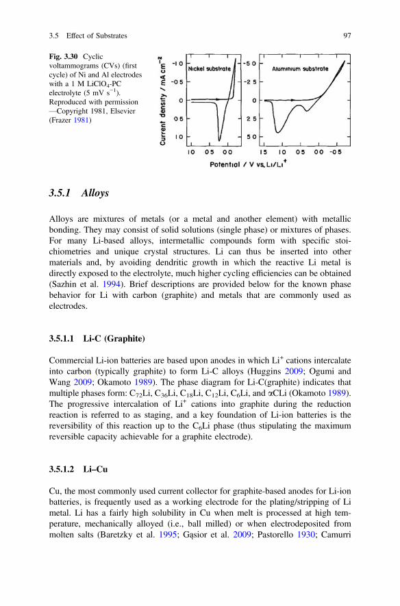
3.5.1 Alloys
Alloys are mixtures of metals (or a metal and another element) with metallicbonding. They may consist of solid solutions (single phase) or mixtures of phases.For many Li-based alloys, intermetallic compounds form with specific stoi-chiometries and unique crystal structures. Li can thus be inserted into othermaterials and, by avoiding dendritic growth in which the reactive Li metal isdirectly exposed to the electrolyte, much higher cycling efficiencies can be obtained(Sazhin et al. 1994). Brief descriptions are provided below for the known phasebehavior for Li with carbon (graphite) and metals that are commonly used aselectrodes.
3.5.1.1 Li-C (Graphite)
Commercial Li-ion batteries are based upon anodes in which Li+ cations intercalateinto carbon (typically graphite) to form Li-C alloys (Huggins 2009; Ogumi andWang 2009; Okamoto 1989). The phase diagram for Li-C(graphite) indicates thatmultiple phases form: C72Li, C36Li, C18Li, C12Li, C6Li, and aCLi (Okamoto 1989).The progressive intercalation of Li+ cations into graphite during the reductionreaction is referred to as staging, and a key foundation of Li-ion batteries is thereversibility of this reaction up to the C6Li phase (thus stipulating the maximumreversible capacity achievable for a graphite electrode).
3.5.1.2 Li–Cu
Cu, the most commonly used current collector for graphite-based anodes for Li-ionbatteries, is frequently used as a working electrode for the plating/stripping of Limetal. Li has a fairly high solubility in Cu when melt is processed at high tem-perature, mechanically alloyed (i.e., ball milled) or when electrodeposited frommolten salts (Baretzky et al. 1995; Gąsior et al. 2009; Pastorello 1930; Camurri
Fig. 3.30 Cyclicvoltammograms (CVs) (firstcycle) of Ni and Al electrodeswith a 1 M LiClO4-PCelectrolyte (5 mV s−1).Reproduced with permission—Copyright 1981, Elsevier(Frazer 1981)
3.5 Effect of Substrates 97

et al. 2003; Lambri et al. 1996, 1999, 2000, 2005; Pérez-Landazábal et al. 2002;Peñaloza et al. 1995). Variable-composition Li-Cu solid solution alloys can thus beformed at elevated temperature up to a composition of approximately 16–18 mol%Li (Pelton 1986c; Gąsior et al. 2009). At lower temperatures, however, there are noindications that Li–Cu solid solutions readily form. Li can thus be plated/strippedon Cu with very high efficiency, although it is possible that some limited reactionoccurs between the Li and Cu at the interface, especially during the first Li platingstep.
3.5.1.3 Li–Al
Li reacts readily with Al (Armstrong et al. 1989; Besenhard 1978; Besenhard et al.1985, 1990; Carpio and King 1981; Fischer and Vissers 1983; Frazer 1981; Fungand Lai 1989; Garreau et al. 1983; Geronov et al. 1984a, b, c; Hamon et al. 2001;Huggins 1999b; Jow and Liang 1982; Morales et al. 2010; Myung et al. 2010;Okamoto 2012b; Park et al. 2002; Rao et al. 1977; Suresh et al. 2002; Zhou et al.2010; Zlatilova et al. 1988; Myung and Yashiro 2014). Figure 3.31 shows that—at423 °C—Li begins to react above 0.35 V (vs. Li/Li+) to form a solid solution withAl (a phase) up to a concentration of close to 10 atom% (or at.%). This is followedby the formation of the AlLi (b) phase until a concentration just below 50 at.%.This phase is then in equilibrium with the Al2Li3 (s) phase until 60 at.%. Furtheraddition of Li results in a liquid phase (at 150 °C). Note that the potential for theformation of the AlLi intermetallic phase varies linearly with temperature (Huggins1999b; Wen et al. 1979). Additional intermetallic phases also form at ambienttemperature, which further complicates the phase behavior when Li is cycled withan Al electrode. Therefore, Al is not usually used as the current collector for Lideposition.
3.5.1.4 Li–Ni
The phase diagram for the Li–Ni system indicates that the solubility of Li in Ni isextremely small and no intermetallic compounds form (Predel 1997d). Ni elec-trodes are therefore frequently used for Li plating/stripping studies, although thehigh cost of Ni tends to preclude its use as a current collector in commercialbatteries.
3.5.1.5 Li–Ti
The phase diagram for the Li–Ti system indicates that the solubility of Li in Ti isextremely small and no intermetallic compounds form (Bale 1989d; Predel 1997f).The two metals are almost completely immiscible, even at high temperature withliquid Li.
98 3 High Coulombic Efficiency of Lithium Plating/Stripping …
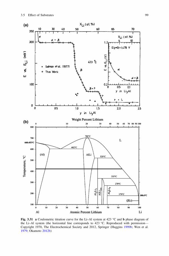
Fig. 3.31 a Coulometric titration curve for the Li–Al system at 423 °C and b phase diagram ofthe Li–Al system (the horizontal line corresponds to 423 °C. Reproduced with permission—Copyright 1970, The Electrochemical Society and 2012, Springer (Huggins 1999b; Wen et al.1979; Okamoto 2012b)
3.5 Effect of Substrates 99

3.5.1.6 Li–W
A phase diagram has not been reported for the Li–W system, but the solubility of Liin W is extremely small and no intermetallic compounds have been identified(Sangster and Pelton 1991a).
3.5.1.7 Li–Pt
Li reacts with Pt to form multiple intermetallic phases (Wibowo et al. 2009; Parket al. 2002; Sangster and Pelton 1991d; Lane et al. 2010b; Bronger et al. 1975,1985). For an IL-based electrolyte containing LiAsF6, after scanning to negativepotential where Li–Pt alloy formation reactions occurred, four different oxidationpeaks were noted when the potential was reversed and scanned positively (Wibowoet al. 2009). These peaks varied in magnitude for different temperatures (25–45 °C),indicating that the reactions progressed to a greater extent at elevated temperatureand that the relative amounts of the different Li–Pt phases formed were also tem-perature dependent (Wibowo et al. 2009).
3.5.1.8 Li–Other Metals
No information is available regarding the phase behavior or corrosion character-istics of SS at low potentials with relevant aprotic Li+-based electrolytes, but SS is acommon cell component for Li-ion batteries and SS electrodes have been used forLi plating/stripping studies with no indications of reactions occurring between theSS and Li (Kim et al. 2013d). Other metals (such as Al and Pt) that have acomplicated phase behavior with Li—with numerous intermetallic phases formedbetween Li and each metal—include Au (Pelton 1986a; Zeng et al. 2014), Ag(Pelton 1986b), Sn (Sangster and Bale 1998; Bailey et al. 1979), Pd (Predel 1997b;Sangster and Pelton 1992), In (Sangster and Pelton 1991c), Ga (Saint et al. 2005;Yuan et al. 2003; Sangster and Pelton 1991b), Pb (Okamoto 1993; Predel 1997e;Wang et al. 1986), Cd (van der Marel et al. 1982; Pelton 1988, 1991; Wang et al.1986), and Zn (Okamoto 2012a; Wang et al. 1986) whereas Li has a negligiblesolubility in Mn (Predel 1997g), Mo (Predel 1997c, 1997h), and Rb (Bale 1989a;Predel 1997a).
3.5.2 Surface Layers and UnderpotentialDeposition/Stripping
Many studies of Li plating/stripping, especially those involving CV measurements,have identified one or more significant redox events prior to 0 V (vs. Li/Li+) during
100 3 High Coulombic Efficiency of Lithium Plating/Stripping …

cathodic scans which are often attributed to the underpotential depostion/stripping(UPD/UPS) of Li monolayers on Al (Li et al. 1999), Au (Aurbach 1989a; Aurbachet al. 1991b; Chang et al. 2001; Gasparotto et al. 2009; Gofer et al. 1995; Mo et al.1996; Saito and Uosaki 2003; Wagner and Gerischer 1989; Zhuang et al. 1995; Liet al. 1986), Ag (Aurbach 1989a; Aurbach et al. 1991b), Pt (Aurbach 1989a;Aurbach et al. 1991b; Chang et al. 2001; Paddon and Compton 2007; Lee et al. 2005;Wibowo et al. 2009), Cu (Chang et al. 2001), and Ni (Li et al. 1998a; b; Wibowoet al. 2009, 2010). This phenomenon refers to the reduction of a metal cation on asolid metal surface at a potential more positive than the Nernst potential—thepotential at which the metal cation will reversibly deposit on the same metal (i.e., forLi, 0 V vs. Li/Li+) (Sudha and Sangaranarayanan 2002). Note that the assignment ofthe redox peaks to Li UPD is speculative in many of these publications with limitedor no validation provided. Some of these reports mention the possibility of Li alloyformation when using Al, Au, Ag, and Pt working electrodes, and Fig. 3.29a indi-cates that the equilibrium alloying potentials for the different Li–Al alloys are morepositive than 0 V versus Li/Li+. Coulometric titration curves for Li binary systemswith Zn, Cd, Pb, Sn, Sb, Bi, In, Ga, and Si reach a similar conclusion (Wang et al.1986; Huggins 1988, 1999b; Wen and Huggins 1980, 1981), and the alloyingpotentials are a function of temperature (Huggins 1989b, 1999a). The diffusion of Liwithin these phases will be a limiting factor for determining which phases form andto what extent. Comparable titration curves are not available for Li binary systemswith Al, Au, Ag, and Pt, but it is reasonable to assume that these metals also formtheir multiple alloy phases at potentials above 0 V versus Li/Li+. Thus, this suggeststhat the redox peaks often attributed to UPD/UPS reactions are instead due toalloying/dealloying reactions (Tavassol et al. 2013).
Why then would redox behavior attributed to UPD be evident on Ni electrodesas well, since Ni does not alloy with Li? Fujieda et al. attributed this to the reactionsof the Ni with trace water—which is reduced near 1 V (vs. Li/Li+) (Fig. 3.32.)(Aurbach 1989a; Aurbach et al. 1991b)—to form an electroactive nickel hydroxideelectrode surface layer (Fujieda et al. 1998). Publications by Kim et al. may also berelevant to the redox reactions noted for Cu and Ni electrodes (Kim et al. 2013d,2011). These authors heated Cu and Ni electrodes in air. At 200 °C and above, theCu surface formed CuO and Cu3O4, whereas at 300 °C and above for Ni, a NiOsurface layer formed. These (nonnative) layers significantly increased the cathodicreactions occurring prior to 0 V vs. Li/Li+, which is unsurprising since the oxidesNiO (Wang et al. 2010; Needham et al. 2006; Liu et al. 2011a; Li et al. 2010; Kimet al. 2011; Huang et al. 2006, 2009) and Cu2O/CuO (Zhang et al. 2004a; Xu et al.2015; Wang et al. 2015b; Shu et al. 2011; Grugeon et al. 2001; Gao et al. 2004;Débart et al. 2001) have been used as anodes that undergo conversion reactions asfollows:
Cu2Oþ 2Liþ þ 2e� $ 2Cu0 þLi2Oþ 2e�
NiOþ 2Liþ þ 2e� $ Ni0 þLi2Oþ 2e�
3.5 Effect of Substrates 101

Given this, it is interesting to note that Aurbach et al. found that the reduction ofdissolved O2 occurs near 2 V (vs. Li/Li+) in aprotic electrolytes (Fig. 3.32)(Aurbach 1989a; Aurbach et al. 1991b). In addition to reacting with Li+ at theelectrode surface to form Li2O, this reduction of O2 may also form metal oxidesurface layers with the respective electrode metals, which then undergo subsequentconversion reactions (and the metals presumably also react with Li2O at themetal-SEI interface). For Al and noble metal electrodes, other oxides such as Al2O3,PtO2, etc., may perhaps also complicate the surface redox reactions. In addition tosuch considerations, aprotic solvents tend to degrade to form surface layers prior to0 V vs. Li/Li+ which further obfuscates the redox reactions occurring on varyingelectrodes prior to Li deposition. This confluence of reactions may explain, in part,the “incubation or initiation period” (which tends to increase with decreasingcurrent density) that is sometimes noted to occur prior to Li plating during gal-vanostatic charging on metal electrodes, as well as the often observed low CE forthe first cycle of Li plating/stripping (Fig. 3.33) (Brissot et al. 1999c; Ota et al.2003, 2004a; Nishikawa et al. 2007, 2010, 2011; Nishida et al. 2013; Sano et al.2014).
Fig. 3.32 Schematic view of typical electrochemical processes occurring in Li salt electrolyteswith PC, THF, and DME on Au and Ag electrodes. Reproduced with permission—Copyright1991, Elsevier (Aurbach et al. 1991b)
102 3 High Coulombic Efficiency of Lithium Plating/Stripping …
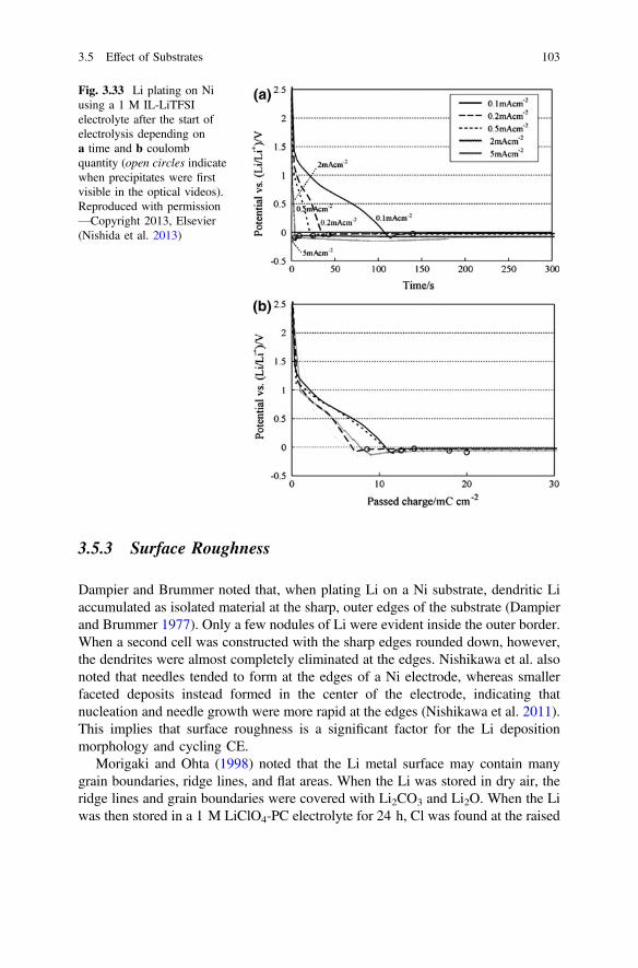
3.5.3 Surface Roughness
Dampier and Brummer noted that, when plating Li on a Ni substrate, dendritic Liaccumulated as isolated material at the sharp, outer edges of the substrate (Dampierand Brummer 1977). Only a few nodules of Li were evident inside the outer border.When a second cell was constructed with the sharp edges rounded down, however,the dendrites were almost completely eliminated at the edges. Nishikawa et al. alsonoted that needles tended to form at the edges of a Ni electrode, whereas smallerfaceted deposits instead formed in the center of the electrode, indicating thatnucleation and needle growth were more rapid at the edges (Nishikawa et al. 2011).This implies that surface roughness is a significant factor for the Li depositionmorphology and cycling CE.
Morigaki and Ohta (1998) noted that the Li metal surface may contain manygrain boundaries, ridge lines, and flat areas. When the Li was stored in dry air, theridge lines and grain boundaries were covered with Li2CO3 and Li2O. When the Liwas then stored in a 1 M LiClO4-PC electrolyte for 24 h, Cl was found at the raised
Fig. 3.33 Li plating on Niusing a 1 M IL-LiTFSIelectrolyte after the start ofelectrolysis depending ona time and b coulombquantity (open circles indicatewhen precipitates were firstvisible in the optical videos).Reproduced with permission—Copyright 2013, Elsevier(Nishida et al. 2013)
3.5 Effect of Substrates 103
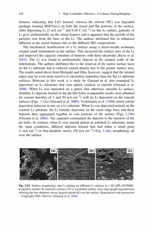
features, indicating that LiCl formed, whereas the solvent (PC) was degraded(perhaps forming ROCO2Li) on both the raised and flat portions of the surface.After depositing Li (2 mA cm−2 and 0.36 C cm−2) on this Li surface, particles ofLi grew preferentially on the raised features and it appeared that the growth of theparticles was from the base of the Li. The authors attributed this to enhanceddiffusion at the raised features due to the different SEI compositions.
The mechanical modification of a Li surface using a micro-needle techniquecreated small indentations in the surface. This increased the surface area of the Liand improved the capacity retention of batteries with these electrodes (Ryou et al.2015). The Li was found to preferentially deposit in the striated walls of theindentations. The authors attributed this to the removal of the native surface layeron the Li substrate and to reduced current density due to the greater surface area.The results noted above from Morigaki and Ohta, however, suggest that the striatededges may be even more reactive to electrolyte impurities than the flat Li substratesurfaces. Relevant to this work is a study by Gireaud et al. that examined Lideposition on Li substrates that were pitted, cracked, or smooth (Gireaud et al.2006). When Li was deposited on a pitted (but otherwise smooth) Li surface,dendritic Li deposits formed in the pit-like holes (comparable results were obtainedfor current densities of 1 and 50 mA cm−2) with no Li deposited on the smoothsurfaces (Figs. 3.34a) (Gireaud et al. 2006). Yoshimatsu et al. (1988) noted similardeposition behavior in pits on a Li substrate. When Li was deposited instead on thecracked Li substrate, the Li initially deposited on the crack ridge lines and thesedeposits then aggregated together to coat portions of the surface (Figs. 3.34b)(Gireaud et al. 2006). The separator constrained the deposits to the interiors of thepit holes. In contrast, when Li was instead plated on polished Li substrates underthe same conditions, different deposits formed that had either a small grain(1 mA cm−2) or free-dendritic mossy (50 mA cm−2) (Fig. 3.34c) morphology allover the surface.
Fig. 3.34 Surface morphology after Li plating on different Li surfaces in 1 M LiPF6-EC/DMC:a pitted Li surface; b cracked Li surface (10 s), c polished surface. Inset micrograph magnificationshowing the free-dendritic mossy deposit spread all over the surface. Reproduced with permission—Copyright 2006, Elsevier (Gireaud et al. 2006)
104 3 High Coulombic Efficiency of Lithium Plating/Stripping …

These factors are well reflected in the cycling characteristics of compressed Lipowder anodes (Kim et al. 1988, 2006, 2007b, 2010b; Kwon et al. 2001; Park andYoon 2003; Hong et al. 2004; Kim and Yoon 2004a, b; Chung et al. 2006; Seonget al. 2008; Kong et al. 2012; Lee et al. 2013). The rougher surface results in ahigher surface area (as compared to Li foil), which reduces the effective currentdensity on the anode, which in turn results in improved cycling characteristics (seebelow) (Park and Yoon 2003). Despite this, the growth in the interfacial impedanceupon storage (aging—see below) was lower for the compressed Li powder than forthe Li foil (Park and Yoon 2003; Kim and Yoon 2004a; Kong et al. 2012). This islikely due to the presence of a thicker native SEI film on the Li powder anode (thanfor the Li foil anode)—as reflected by an initially greater impedance for the powderelectrode—which may suppress further reactions with the electrolyte to a greaterextent (Hong et al. 2004; Kim and Yoon 2004a), as well as differences in reactivitywith the electrolyte components due to the surface roughness. Rather than isolatedpitting on the flat Li surface during stripping and subsequent deposition inside thepits as observed for the Li foil, the stripping of Li from the powder occurredrelatively uniformly across the entire electrode, forming pits within the powderspheres. Deposition then occurred within the pits to reconstruct the compressedspheres (Kim et al. 2006, 2007b; Seong et al. 2008; Kong et al. 2012). Duringcycling, this resulted in lower electrolyte consumption, less dendritic growth, andreduced interphasial layer formation (Kim and Yoon 2004b; Chung et al. 2006;Kim et al. 2010b).
3.6 Influence of Charge/Discharge Profiles
3.6.1 Influence of Pulsed Plating
A coarse grain simulation model for the plating of Li metal—which accounts for theheterogeneous and nonequilibrium nature of the plating dynamics, as well as thelong time- and length-scales for dendrite growth—found that dendrite formationincreased with an increase in the applied overpotential, and the application ofpulsed charging significantly suppressed dendrite formation at high overpotentials(Mayers et al. 2012). According to this model, dendrite growth reflects a compe-tition between the time scales for Li+ cation diffusion/reduction to/at the anode-SEIinterface. The use of low overpotentials or short charging pulses favors cationdiffusion, thus decreasing the proclivity for dendrite formation. This has beenexperimentally validated using Li/Li cells with a 1 M LiPF6-EC/DMC (1/1 v/v)electrolyte by comparing the morphology of Li deposited by direct current(DC) and either pulse plating (PP) or reverse pulsed plating (RPP) (Fig. 3.35)(Yang et al. 2014). The PP method with short, widely spaced current pulsesimproved both the Li morphology (larger Li particles/nodules) and the cycling CE.
3.5 Effect of Substrates 105
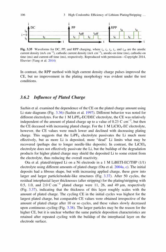
In contrast, the RPP method with high current density charge pulses improved theCE, but no improvement in the plating morphology was evident under the testconditions.
3.6.2 Influence of Plated Charge
Sazhin et al. examined the dependence of the CE on the plated charge amount usingLi state diagrams (Fig. 3.36) (Sazhin et al. 1997). Different behavior was noted fordifferent electrolytes. For the 1 M LiPF6-EC/DEC electrolyte, the CE was relativelyindependent of the amount of plated charge up to a value of 0.23 C cm−2, but thenthe CE deceased with increasing plated charge. For the 1 M LiClO4-EC electrolyte,however, the CE values were much lower and declined with decreasing platingcharge. This suggests that the LiPF6 electrolyte passivates the Li much moreeffectively, but as more Li is deposited, more “dead” Li limits what may berecovered (perhaps due to longer needle-like deposits). In contrast, the LiClO4
electrolyte does not effectively passivate the Li, but the buildup of the degradationproducts for higher plated charge may shield the deposited Li to some extent fromthe electrolyte, thus reducing the overall reactivity.
Ota et al. plated/stripped Li on a Ni electrode in a 1 M LiBETI-EC/THP (1/1)electrolyte using different amounts of plated charge (Ota et al. 2004a, c). The initialdeposits had a fibrous shape, but with increasing applied charge, these grew intolarger and larger particle/nodule-like structures (Fig. 3.37). After 50 cycles, theresidual interphasial layer thicknesses (after stripping) for the plating/stripping with0.5, 1.0, and 2.0 C cm−2 plated charge were 11, 26, and 49 µm, respectively(Fig. 3.37), indicating that the thickness of this layer roughly scales with theamount of plated charge. The cycling CE in the initial cycles was highest for thelargest plated charge, but comparable CE values were obtained irrespective of theamount of plated charge after 10 or so cycles, and these values slowly decreasedupon continuous cycling (Fig. 3.38). The larger particles may be the reason for thehigher CE, but it is unclear whether the same particle deposition characteristics areretained after repeated cycling with the buildup of the interphasial layer on theelectrode surface.
Fig. 3.35 Waveforms for DC, PP, and RPP charging, where ia, ic, ta, tc, and toff are the anodiccurrent density (mA cm−2), cathodic current density (mA cm−2), anodic-on time (ms), cathodic-ontime (ms) and current-off time (ms), respectively. Reproduced with permission—Copyright 2014,Elsevier (Yang et al. 2014)
106 3 High Coulombic Efficiency of Lithium Plating/Stripping …
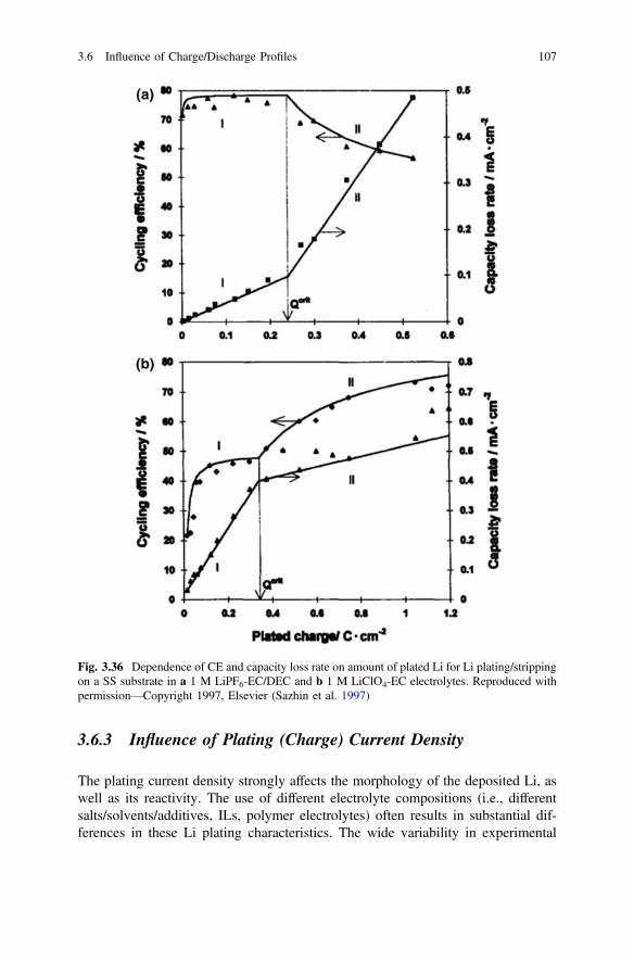
3.6.3 Influence of Plating (Charge) Current Density
The plating current density strongly affects the morphology of the deposited Li, aswell as its reactivity. The use of different electrolyte compositions (i.e., differentsalts/solvents/additives, ILs, polymer electrolytes) often results in substantial dif-ferences in these Li plating characteristics. The wide variability in experimental
Fig. 3.36 Dependence of CE and capacity loss rate on amount of plated Li for Li plating/strippingon a SS substrate in a 1 M LiPF6-EC/DEC and b 1 M LiClO4-EC electrolytes. Reproduced withpermission—Copyright 1997, Elsevier (Sazhin et al. 1997)
3.6 Influence of Charge/Discharge Profiles 107
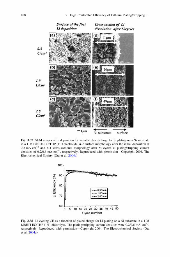
Fig. 3.37 SEM images of Li deposition for variable plated charge for Li plating on a Ni substratein a 1 M LiBETI-EC/THP (1:1) electrolyte: a–c surface morphology after the initial deposition at0.2 mA cm−2 and d–f cross-sectional morphology after 50 cycles at plating/stripping currentdensities of 0.2/0.6 mA cm−2, respectively. Reproduced with permission—Copyright 2004, TheElectrochemical Society (Ota et al. 2004a)
Fig. 3.38 Li cycling CE as a function of plated charge for Li plating on a Ni substrate in a 1 MLiBETI-EC/THP (1/1) electrolyte. The plating/stripping current densities were 0.2/0.6 mA cm−2,respectively. Reproduced with permission—Copyright 2004, The Electrochemical Society (Otaet al. 2004a)
108 3 High Coulombic Efficiency of Lithium Plating/Stripping …
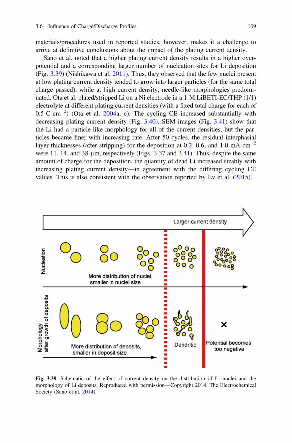
materials/procedures used in reported studies, however, makes it a challenge toarrive at definitive conclusions about the impact of the plating current density.
Sano et al. noted that a higher plating current density results in a higher over-potential and a corresponding larger number of nucleation sites for Li deposition(Fig. 3.39) (Nishikawa et al. 2011). Thus, they observed that the few nuclei presentat low plating current density tended to grow into larger particles (for the same totalcharge passed), while at high current density, needle-like morphologies predomi-nated. Ota et al. plated/stripped Li on a Ni electrode in a 1 M LiBETI-EC/THP (1/1)electrolyte at different plating current densities (with a fixed total charge for each of0.5 C cm−2) (Ota et al. 2004a, c). The cycling CE increased substantially withdecreasing plating current density (Fig. 3.40). SEM images (Fig. 3.41) show thatthe Li had a particle-like morphology for all of the current densities, but the par-ticles became finer with increasing rate. After 50 cycles, the residual interphasiallayer thicknesses (after stripping) for the deposition at 0.2, 0.6, and 1.0 mA cm−2
were 11, 14, and 38 µm, respectively (Figs. 3.37 and 3.41). Thus, despite the sameamount of charge for the deposition, the quantity of dead Li increased sizably withincreasing plating current density—in agreement with the differing cycling CEvalues. This is also consistent with the observation reported by Lv et al. (2015).
Fig. 3.39 Schematic of the effect of current density on the distribution of Li nuclei and themorphology of Li deposits. Reproduced with permission—Copyright 2014, The ElectrochemicalSociety (Sano et al. 2014)
3.6 Influence of Charge/Discharge Profiles 109
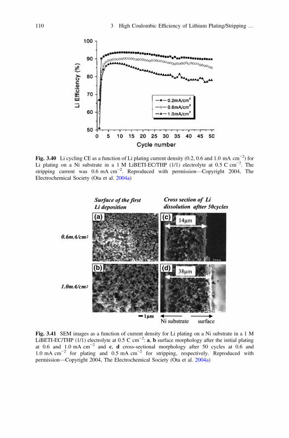
Fig. 3.40 Li cycling CE as a function of Li plating current density (0.2, 0.6 and 1.0 mA cm−2) forLi plating on a Ni substrate in a 1 M LiBETI-EC/THP (1/1) electrolyte at 0.5 C cm−2. Thestripping current was 0.6 mA cm−2. Reproduced with permission—Copyright 2004, TheElectrochemical Society (Ota et al. 2004a)
Fig. 3.41 SEM images as a function of current density for Li plating on a Ni substrate in a 1 MLiBETI-EC/THP (1/1) electrolyte at 0.5 C cm−2: a, b surface morphology after the initial platingat 0.6 and 1.0 mA cm−2 and c, d cross-sectional morphology after 50 cycles at 0.6 and1.0 mA cm−2 for plating and 0.5 mA cm−2 for stripping, respectively. Reproduced withpermission—Copyright 2004, The Electrochemical Society (Ota et al. 2004a)
110 3 High Coulombic Efficiency of Lithium Plating/Stripping …
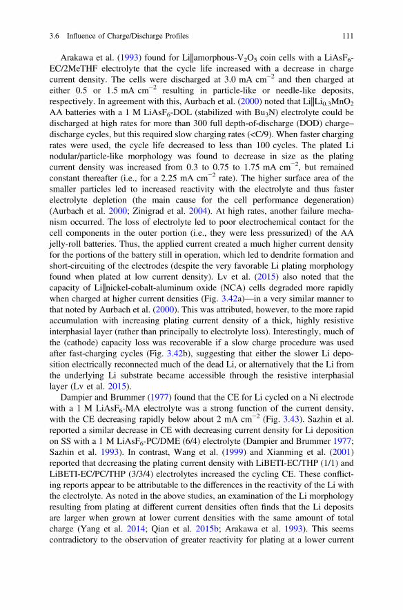
Arakawa et al. (1993) found for Li||amorphous-V2O5 coin cells with a LiAsF6-EC/2MeTHF electrolyte that the cycle life increased with a decrease in chargecurrent density. The cells were discharged at 3.0 mA cm−2 and then charged ateither 0.5 or 1.5 mA cm−2 resulting in particle-like or needle-like deposits,respectively. In agreement with this, Aurbach et al. (2000) noted that Li||Li0.3MnO2
AA batteries with a 1 M LiAsF6-DOL (stabilized with Bu3N) electrolyte could bedischarged at high rates for more than 300 full depth-of-discharge (DOD) charge–discharge cycles, but this required slow charging rates (<C/9). When faster chargingrates were used, the cycle life decreased to less than 100 cycles. The plated Linodular/particle-like morphology was found to decrease in size as the platingcurrent density was increased from 0.3 to 0.75 to 1.75 mA cm−2, but remainedconstant thereafter (i.e., for a 2.25 mA cm−2 rate). The higher surface area of thesmaller particles led to increased reactivity with the electrolyte and thus fasterelectrolyte depletion (the main cause for the cell performance degeneration)(Aurbach et al. 2000; Zinigrad et al. 2004). At high rates, another failure mecha-nism occurred. The loss of electrolyte led to poor electrochemical contact for thecell components in the outer portion (i.e., they were less pressurized) of the AAjelly-roll batteries. Thus, the applied current created a much higher current densityfor the portions of the battery still in operation, which led to dendrite formation andshort-circuiting of the electrodes (despite the very favorable Li plating morphologyfound when plated at low current density). Lv et al. (2015) also noted that thecapacity of Li||nickel-cobalt-aluminum oxide (NCA) cells degraded more rapidlywhen charged at higher current densities (Fig. 3.42a)—in a very similar manner tothat noted by Aurbach et al. (2000). This was attributed, however, to the more rapidaccumulation with increasing plating current density of a thick, highly resistiveinterphasial layer (rather than principally to electrolyte loss). Interestingly, much ofthe (cathode) capacity loss was recoverable if a slow charge procedure was usedafter fast-charging cycles (Fig. 3.42b), suggesting that either the slower Li depo-sition electrically reconnected much of the dead Li, or alternatively that the Li fromthe underlying Li substrate became accessible through the resistive interphasiallayer (Lv et al. 2015).
Dampier and Brummer (1977) found that the CE for Li cycled on a Ni electrodewith a 1 M LiAsF6-MA electrolyte was a strong function of the current density,with the CE decreasing rapidly below about 2 mA cm−2 (Fig. 3.43). Sazhin et al.reported a similar decrease in CE with decreasing current density for Li depositionon SS with a 1 M LiAsF6-PC/DME (6/4) electrolyte (Dampier and Brummer 1977;Sazhin et al. 1993). In contrast, Wang et al. (1999) and Xianming et al. (2001)reported that decreasing the plating current density with LiBETI-EC/THP (1/1) andLiBETI-EC/PC/THP (3/3/4) electrolytes increased the cycling CE. These conflict-ing reports appear to be attributable to the differences in the reactivity of the Li withthe electrolyte. As noted in the above studies, an examination of the Li morphologyresulting from plating at different current densities often finds that the Li depositsare larger when grown at lower current densities with the same amount of totalcharge (Yang et al. 2014; Qian et al. 2015b; Arakawa et al. 1993). This seemscontradictory to the observation of greater reactivity for plating at a lower current
3.6 Influence of Charge/Discharge Profiles 111

Fig. 3.42 Electrochemical evaluation of Li||NCA cells: a cycling stability of cells charged atvarious C rates and discharged at 1C, with two formation cycles initially performed at 0.1 C forboth charge and discharge and b cycling stability of the cell initially cycled at 2 C for 500 cyclesand then switched to 0.1 C. Reproduced with permission—Copyright 2014, Wiley-VCH (Lv et al.2015)
Fig. 3.43 Li cycling CE as a function of current density on a Ni substrate for a 1 M LiAsF6-MAelectrolyte. Q = 0.83 C cm−2 and iplate = istrip in all cases (data for second cycle of fresh cells),where iplate and istrip are the Li plating and striping current density, respectively. Reproduced withpermission—Copyright 1977, Elsevier (Dampier and Brummer 1977)
112 3 High Coulombic Efficiency of Lithium Plating/Stripping …

density that is sometimes noted, since larger Li particles will have less surface areaexposed to the electrolyte. But a second important factor to consider is the timeperiod required to achieve a specified total plated charge, which varies directly withthe current density, with much longer periods required for lower current densities,thus enabling more time for side reactions to occur (Dampier and Brummer 1977).
Nishida et al. (2013) found rather different plating features when studying thegrowth for an unconstrained electrode (i.e., no separator and associated stackpressure). These authors monitored the Li deposition morphology on a Ni substratewith an IL electrolyte using in situ optical microscopy (Fig. 3.44). For a low currentdensity of 0.1 mA cm−2, long needle-like growth was evident. Increasing thecurrent density to 0.2 mA cm−2 reduced the number of these and their extendedgrowth did not occur until more charge had been applied. Above 0.5 mA cm−2, theneedle-like growth transformed to a complex structure similar to seaweed withrelatively smooth deposits retained until 300 mC cm−2 was applied. Thus, dendriteswere most prominent for both low and high plating current densities. It is unclearwhy these results differ from those in past studies.
The Li deposition morphology dependence on plating current density alsoappears to differ for studies with polymer electrolytes. Brissot et al. found that, on aLi substrate and a LiTFSI-PEO polymer electrolyte, at low current density(0.2 mA cm−2), needle- and small particle-like deposits formed, whereas for highercurrent densities (� 0.7 mA cm−2), the deposits were initially compact layers for
Fig. 3.44 Time transients of the morphology of plated Li on a Ni substrate in a 1 M LiTFSI-ILelectrolyte as a function of current density and total current. Reproduced with permission—Copyright 2013, Elsevier (Nishida et al. 2013)
3.6 Influence of Charge/Discharge Profiles 113

the first few cycles, but then formed tree- or bush-like deposits upon continuedcycling (Brissot et al. 1998). In situ optical studies of cells with a LiTFSI-P(EO)n(n = 15–40) SPE electrolyte (cycled at 80 °C under constant-current conditions)found that at low plating current density (0.2 mA cm−2), needle-like andparticle-like dendrites formed. At higher plating current densities, dendrites did notform during the first polarization step (Brissot et al. 1998, 1999c). Instead, acompact Li layer formed. After several polarizations, however, dendrites did form,but now with a tree-like or bush-like morphology. New dendrites were neverobserved to grow on top of the dendrites produced during previous polarization.Instead they grew directly on the electrode until the entire electrode was eventuallycovered with them (Brissot et al. 1998). This may be due to the passivation of thedendritic Li metal surface by reactions with the electrolyte. The needle-like den-drites tended to grow either straight across the electrolyte (thus forming a shortcircuit with the positive electrode) or instead adopt a tortuous shape that may neverinduce a short circuit (Brissot et al. 1999c). Interestingly, the decrease in saltconcentration near the negative electrode during cycling resulted in a compaction ofthe SPE, while the SPE “inflated” near the positive counter electrode (Brissot et al.1998). This electrolyte motion is destructive to the dendrites and can lead to dis-connections of dendrites that contact the positive electrode, thus resulting in vari-able short-circuiting behavior from cycle to cycle. The experimental conditions forthe in situ measurements, however, differ significantly from a full battery and thusthese observations may not be directly transferable. A very similar Li dendritemorphology versus current density trend was noted for a liquid LiTFSI-P(EO)nelectrolyte (with low molecular weight PEO) (Zhang et al. 2004b). A higher platingcurrent density, however, may result in more branching at defect sites (kinks) on theneedles; thus, the tree- or bush-like Li deposits may well be generated from rapidlybranching needles rather than particle-like (nodular) deposits.
3.6.4 Influence of Stripping (Discharge) Current Density
Schedlbauer et al. (2013) examined the cycling CE dependence of Liplating/stripping on a Cu electrode using 1 M LiPF6- or LiDFOB-EC/DEC (3/7 wt)electrolytes. The plating was done at 0.1 mA cm−2, whereas the stripping rate wasvaried from 0.1 to 1.0 mA cm−2. Interestingly, these authors found that the CEdecreased with increasing stripping current density, which contradicts what othershave found, as noted below. One possible reason for this is that the stripping currentdensity was changed (i.e., increased by 0.1 mA cm−2 increments) for the same cellafter 10 cycles (instead of using separate cells) (Schedlbauer et al. 2013). Given thatthe CE is not stable for carbonate-based electrolytes and tends to decrease uponextended cycling, this may account for the disagreement. In contrast, Dampier andBrummer (1977) found that stripping the Li from a Ni electrode using a 1 MLiAsF6-MA electrolyte at a low current density leads to a lower cycling CE than
114 3 High Coulombic Efficiency of Lithium Plating/Stripping …

doing so at a higher current density (for Li plated at the same current density)(Fig. 3.45). This was attributed to the exposure of newly exposed Li to the elec-trolyte (after disrupting the SEI as the Li was stripped) for a longer period of timefor slower discharge rates. Wang et al. (1999) noted the same trend when using aLiBET-EC/THP (1:1 in volume ratio) electrolyte.
Laman and Brandt (1988) also found that the cycle life for Li||MoS2 batterieswith a 1 M LiAsF6-EC/PC (1/1 v/v) electrolyte was strongly dependent on thedischarge rate (when a constant charge rate was used). For very high dischargerates, the cycle life limitations were attributed to unfavorable cathode reactions. Forintermediate discharge rates, the slow buildup of high cell impedance due toelectrolyte decomposition (and the growth of the interphasial layer) eventuallylimited the battery (cycle) life. For low discharge rates, however, the cycle life wassignificantly shorter due to low-impedance failure (i.e., short-circuit formation bydendrites).
Arakawa et al. (1993) indicated that comparable trends had been reported forLi/MnO2 and Li||Li0.5MnOy cells despite these having different cathodes, elec-trolytes, capacities, charge current densities, and cycling voltage ranges. Theseauthors extended the study of Laman and Brandt using the Li/a-V2O5 coin cellswith a LiAsF6-EC/2MeTHF electrolyte. They also noted that the cycle lifeincreased with an increase in discharge current density (0.2 vs. 3.0 mA cm−2).Localized stripping occurred for the low discharge rate, while delocalized strippingwas evident for the high rate. This was attributed to variations in the resistance inthe SEI. For the low rate, the induced overpotential may not be sufficient to strip theLi from the more resistive parts of the SEI, but the higher overpotential at higherrates may drive stripping from a greater portion of the Li surface. When the cells
Fig. 3.45 Unrecoverable(dead) Li as a function of totaltime (plating, stripping andaging) for Li plating/strippingon a Ni substrate with a 1 MLiAsF6-MA electrolyte.Q = 0.83 C cm−2,iplate = plating current density(mA cm−2) andistrip = stripping currentdensity (mA cm−2) (data forsecond cycle of fresh cells).Reproduced with permission—Copyright 1977, Elsevier)(Dampier and Brummer 1977)
3.6 Influence of Charge/Discharge Profiles 115
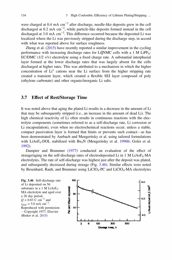
were charged at 0.4 mA cm−2 after discharge, needle-like deposits grew in the celldischarged at 0.2 mA cm−2, while particle-like deposits formed instead in the celldischarged at 3.0 mA cm−2. This difference occurred because the deposited Li waslocalized where the Li was previously stripped during the discharge step, in accordwith what was reported above for surface roughness.
Zheng et al. (2015) have recently reported a similar improvement in the cyclingperformance with increasing discharge rates for Li||NMC cells with a 1 M LiPF6-EC/DMC (1/2 v/v) electrolyte using a fixed charge rate. A substantial interphasiallayer formed at the lower discharge rates that was largely absent for the cellsdischarged at higher rates. This was attributed to a mechanism in which the higherconcentration of Li+ cations near the Li surface from the higher stripping ratecreated a transient layer, which created a flexible SEI layer composed of poly(ethylene carbonate) and other organic/inorganic Li salts.
3.7 Effect of Rest/Storage Time
It was noted above that aging the plated Li results in a decrease in the amount of Lithat may be subsequently stripped (i.e., an increase in the amount of dead Li). Thehigh chemical reactivity of Li often results in continuous reactions with the elec-trolyte components (sometimes referred to as a self-discharge rate, Li corrosion orLi encapsulation), even when no electrochemical reactions occur, unless a stable,compact passivation layer is formed that limits or prevents such contact—as hasbeen demonstrated by Aurbach and Mengeritsky et al. using tailored formulationswith LiAsF6-DOL stabilized with Bu3N (Mengeritsky et al. 1996b; Gofer et al.1992).
Dampier and Brummer (1977) conducted an evaluation of the effect ofstorage/aging on the self-discharge rates of electrodeposited Li in 1 M LiAsF6-MAelectrolytes. The rate of self-discharge was highest just after the deposit was plated,and subsequently decreased during storage (Fig. 3.46). Similar effects were notedby Besenhard, Rauh, and Brummer using LiClO4-PC and LiClO4-MA electrolytes
Fig. 3.46 Self-discharge rateof Li deposited on Nisubstrates in a 1 M LiAsF6-MA electrolyte and aged overa 26 day period.Q = 0.83 C cm−2 andiplate = 5.0 mA cm−2.Reproduced with permission—Copyright 1977, Elsevier(Bieker et al. 2015)
116 3 High Coulombic Efficiency of Lithium Plating/Stripping …

Fig. 3.47 Impedance spectra of Li||Li cells with a 1 M LiPF6-EC/DEC (3:7) electrolyte: a after 0,1, 3, and 6 days at OCP and b after 50 and 370 plating/stripping cycles at 0.1 mA cm−2. c Selectedoverpotential profiles for the cells. Reproduced with permission—Copyright 2015, The RoyalSociety of Chemistry (Ota et al. 2004a)
3.7 Effect of Rest/Storage Time 117
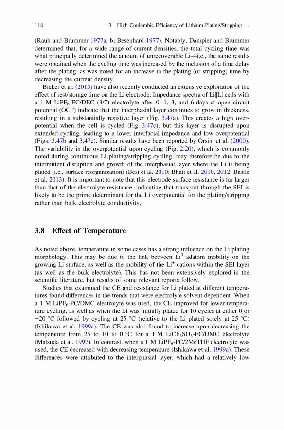
(Rauh and Brummer 1977a, b; Besenhard 1977). Notably, Dampier and Brummerdetermined that, for a wide range of current densities, the total cycling time waswhat principally determined the amount of unrecoverable Li—i.e., the same resultswere obtained when the cycling time was increased by the inclusion of a time delayafter the plating, as was noted for an increase in the plating (or stripping) time bydecreasing the current density.
Bieker et al. (2015) have also recently conducted an extensive exploration of theeffect of rest/storage time on the Li electrode. Impedance spectra of Li||Li cells witha 1 M LiPF6-EC/DEC (3/7) electrolyte after 0, 1, 3, and 6 days at open circuitpotential (OCP) indicate that the interphasial layer continues to grow in thickness,resulting in a substantially resistive layer (Fig. 3.47a). This creates a high over-potential when the cell is cycled (Fig. 3.47c), but this layer is disrupted uponextended cycling, leading to a lower interfacial impedance and low overpotential(Figs. 3.47b and 3.47c). Similar results have been reported by Orsini et al. (2000).The variability in the overpotential upon cycling (Fig. 2.20), which is commonlynoted during continuous Li plating/stripping cycling, may therefore be due to theintermittent disruption and growth of the interphasial layer where the Li is beingplated (i.e., surface reorganization) (Best et al. 2010; Bhatt et al. 2010, 2012; Basileet al. 2013). It is important to note that this electrode surface resistance is far largerthan that of the electrolyte resistance, indicating that transport through the SEI islikely to be the prime determinant for the Li overpotential for the plating/strippingrather than bulk electrolyte conductivity.
3.8 Effect of Temperature
As noted above, temperature in some cases has a strong influence on the Li platingmorphology. This may be due to the link between Li0 adatom mobility on thegrowing Li surface, as well as the mobility of the Li+ cations within the SEI layer(as well as the bulk electrolyte). This has not been extensively explored in thescientific literature, but results of some relevant reports follow.
Studies that examined the CE and resistance for Li plated at different tempera-tures found differences in the trends that were electrolyte solvent dependent. Whena 1 M LiPF6-PC/DMC electrolyte was used, the CE improved for lower tempera-ture cycling, as well as when the Li was initially plated for 10 cycles at either 0 or−20 °C followed by cycling at 25 °C (relative to the Li plated solely at 25 °C)(Ishikawa et al. 1999a). The CE was also found to increase upon decreasing thetemperature from 25 to 10 to 0 °C for a 1 M LiCF3SO3-EC/DMC electrolyte(Matsuda et al. 1997). In contrast, when a 1 M LiPF6-PC/2MeTHF electrolyte wasused, the CE decreased with decreasing temperature (Ishikawa et al. 1999a). Thesedifferences were attributed to the interphasial layer, which had a relatively low
118 3 High Coulombic Efficiency of Lithium Plating/Stripping …

resistance for the DMC-containing electrolyte, but a much more resistive layer forthe 2MeTHF electrolyte.
To examine the effect of temperature on the plating morphology, Ota et al.(2004a) deposited Li on Ni from 1 M LiX-EC/THF (1/1) electrolytes with eitherLiPF6, LiTFSI or LiBETI at 0, 25, or 50 °C (Fig. 3.48). Notably, at 50 °C the Liparticles were larger and somewhat flat, whereas at 0 °C the Li particles were muchsmaller for the electrolyte with LiBETI, but were dendritic fibers for the electrolyteswith LiPF6 and LiTFSI. Impedance spectroscopy was used to examine the resis-tance of the deposited Li. The Li deposited at 50 °C in the LiPF6 electrolyte had ahigher resistance and lower CE than the Li deposited in the LiTFSI and LiBETIelectrolytes (Fig. 3.49). This may, in part, be due to the larger particle size and thuslower surface area of the former.
On switching to 25 °C, the resistance of the Li from LiPF6 remained higher, butthe value decreased upon continuous cycling and the CE improved (Fig. 3.50a).When the Li was instead initially deposited and cycled at 0 °C, the resistance and
Fig. 3.48 SEM images as a function of temperature of Li deposited on a Ni substrate in 1 MLiX-EC/THF (1:1) electrolytes containing LiPF6, LiTFSI and LiBETI, respectively: a–c 0 °C, d–f 25 °C and g–i 50 °C. The plating current was 0.6 mA cm−2 up to 0.5 C cm−2. Reproduced withpermission—Copyright 2004, The Electrochemical Society (Ota et al. 2004a)
3.8 Effect of Temperature 119

Fig. 3.49 Impedance plotsafter the initial Li plating as afunction of electrolytetemperature in 1 MLiX-EC/THF (1/1)electrolytes containing LiPF6,LiTFSI, and LiBETI,respectively: a 0 °C, b 25 °Cand c 50 °C. The platingcurrent was 0.6 mA cm−2 upto 0.5 C cm−2. Reproducedwith permission—Copyright2004, The ElectrochemicalSociety (Ota et al. 2004a)
120 3 High Coulombic Efficiency of Lithium Plating/Stripping …
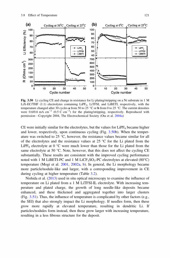
CE were initially similar for the electrolytes, but the values for LiPF6 became higherand lower, respectively, upon continuous cycling (Fig. 3.50b). When the temper-ature was switched to 25 °C, however, the resistance values became similar for allof the electrolytes and the resistance values at 25 °C for the Li plated from theLiPF6 electrolyte at 0 °C were much lower than those for the Li plated from thesame electrolyte at 50 °C. Note, however, that this does not affect the cycling CEsubstantially. These results are consistent with the improved cycling performancenoted with 1 M LiBETI-PC and 1 M LiCF3SO3-PC electrolytes at elevated (80°C)temperature (Mogi et al. 2001, 2002a, b). In general, the Li morphology becamemore particle/nodule-like and larger, with a corresponding improvement in CEduring cycling at higher temperature (Table 3.2).
Nishida et al. (2013) used in situ optical microscopy to examine the influence oftemperature on Li plated from a 1 M LiTFSI-IL electrolyte. With increasing tem-perature and plated charge, the growth of long needle-like deposits becameenhanced, and these thickened and aggregated together into larger clusters(Fig. 3.51). Thus, the influence of temperature is complicated by other factors (e.g.,the SEI) that also strongly impact the Li morphology. If needles form, then thesegrow more rapidly at elevated temperature, resulting in dendritic Li. Ifparticles/nodules form instead, then these grow larger with increasing temperature,resulting in a less fibrous structure for the deposit.
Fig. 3.50 Li cycling CE and change in resistance for Li plating/stripping on a Ni substrate in 1 MLiX-EC/THF (1:1) electrolytes containing LiPF6, LiTFSI, and LiBETI, respectively, with thetemperature changed after 30 cycles a from 50 to 25 °C or b from 0 to 25 °C. The current densitieswere 0.6/0.6 mA cm−2 (0.5 C cm−2) for the plating/stripping, respectively. Reproduced withpermission—Copyright 2004, The Electrochemical Society (Ota et al. 2004a)
3.8 Effect of Temperature 121

Table 3.2 Effect of electrolyte temperature on Li deposition in 1 M LiX-EC/THF (1/1)electrolytes (Ota et al. 2004a)
Li cycle CE (%)
Salt Temperature Avg.1–20cycles
Avg.1–50cycles
Cyclestability
Morphology Thicknessafter 50cycles (µm)
LiPF6 0 78 74 Bad Dendritic 29
25 80 80 Good Particle/dendritic 24
50 81 79 Good Large particles 41
LiTFSI 0 81 72 Bad Dendritic 26
25 87 83 Bad Dendritic 29
50 89 89 Verygood
Large particles 31
LiBETI 0 83 81 Good Fine particles 24
25 87 88 Verygood
Particles 15
50 89 89 Verygood
Large particles 24
Fig. 3.51 Time transients of the morphology of plated Li on a Ni substrate in a 1 M LiTFSI-ILelectrolyte as a function of temperature and total current. Reproduced with permission—Copyright2013, Elsevier (Nishida et al. 2013)
122 3 High Coulombic Efficiency of Lithium Plating/Stripping …

3.9 Effect of Stack Pressure
Stack pressure has a dramatic influence on the compactness and porosity of theplated Li (Fig. 3.52) and thus on the exposure of the Li to the electrolyte.A reduction in the Li surface area results in less overall SEI formation and betterelectrical contact with the current collector. This, in turn, results in an improvedcycling CE and possibly a reduced propensity for dendrites to contact the cathodes.
Hirai et al. noted improvements in the Li cycling CE with increasing stackpressure using a coin-type cell pressurized by a hydraulic hand press using a varietyof electrolytes containing different mixtures of solvents (EC, PC, 2MeTHF) andsalts (LiAsF6, LiPF6, LiCF3SO3) (Hirai et al. 1994a, b). The cells contained acathode (70 wt% a-V2O5-P2O5, 25 wt% acetylene black, and 5 wt% polyte-trafluoroethylene [PTFE]) and a Li disk anode with a Celgard 5511 separator (forPC-based electrolytes) or Celgard 2502 separator (for other electrolytes). The Licycling CE was evaluated using an “accelerated test” in which the cycling capacity
Fig. 3.52 SEM images of Li microstructures formed under different external pressures aftercharging at a current density of 1.1 mA cm−2 for 240 min for a cell with a Celgard separator and1 M LiPF6-EC/DEC: a, b surface microstructure, c, d surface image, and e, f cross-sectionalimage. Reproduced with permission—Copyright 2015, The American Chemical Society (Changet al. 2015)
3.9 Effect of Stack Pressure 123

of the cell was limited by the Li content (Hirai et al. 1994a). Interestingly, when theelectrolyte salt and salt concentration were kept constant (i.e., 1.5 M LiAsF6), asubstantial difference in the efficiency was found for different solvents. The cellwith LiAsF6-EC/2MeTHF had a large increase in efficiency with increasing pres-sure, as did the cell with LiAsF6-2MeTHF, although to a lesser extent. A muchsmaller effect was seen for the cells with the LiAsF6-EC/PC and LiAsF6-PCelectrolytes, but this may be attributable to the use of a different separator. For thecells with the same solvent mixture (EC/2MeTHF), but different (1.5 M) Li salts, asubstantial improvement with increasing pressure was found for the cell with theLiAsF6-based electrolyte, whereas a pressure increase in the cells with the elec-trolytes containing LiPF6 and LiCF3SO3 was much less beneficial to the cycling CE(Hirai et al. 1994a).
Swagelok cells equipped with springs of differing stiffness have been used byGireaud et al. (2006) to explore the influence of stack pressure on Li plating. Theworking electrode was an SUS 16L SS plate and the electrolyte was a 1 M LiPF6-EC/DMC electrolyte. Increasing pressure resulted in more compact Li plating,which in turn resulted in a higher CE for the cycling. Similarly, Eweka et al. (1997)used a spring and screwable cell lid to apply stack pressure and found that a notableimprovement in the cycling CE was evident when using a 1 M LiAsF6-EC/PCelectrolyte. Without the stack pressure, the initial cycling CE was below 70 %, andthis rose to approximately 90 % with the applied pressure, but the effect was notpersistent, as the CE began to rapidly decline after 25–35 cycles.
Wilkinson and Wainwright reported highly informative studies using aforce-displacement apparatus to measure the electrode thickness as a function ofpressure during cycling (Wilkinson et al. 1991; Wilkinson and Wainwright 1993).For Li||LixMoS2 flat plate cells with a 1 M LiAsF6-PC electrolyte, there was astrong correlation between the pressure and the Li cycling CE, with a markedimprovement at high pressure (especially above a critical pressure of 60–80 psi).SEM images of the Li electrodes indicated that a very different Li plating mor-phology occurred below and above this critical pressure. At low pressure, a porousLi deposit formed with a variety of differently shaped crystals (needle-like andlump-shaped). At 200 psi, however, the deposit instead consisted of closed-packedcolumns extending from the uncycled Li substrate (Wilkinson et al. 1991). Theimproved cycling CE noted at higher pressure was attributed to the decreasedsurface area of the compact Li metal, and thus decreased rate of reaction with theelectrolyte. A large change in the electrode stack thickness was noted duringcycling since the volume of the plated Li metal is greater than the volume decreaseof the cathode material due to delithiation (Fig. 3.53a) (Wilkinson et al. 1991). Fortwo cells at different pressures, in addition to this cyclic variation in thickness fromthe Li metal plating/stripping, there is a net increase in the stack thickness for bothcells, but substantially more for the cell with the lower applied pressure (Fig. 3.53b)(Wilkinson et al. 1991) due to the more rapid accumulation of a thick interphasiallayer (Wilkinson and Wainwright 1993). The average net growth per cycle variedwith the electrolyte used, as might be expected from differences in electrolytecomponent reactivity with the Li metal, with a 0.75 M LiAsF6-sulfolane/tri-glyme
124 3 High Coulombic Efficiency of Lithium Plating/Stripping …
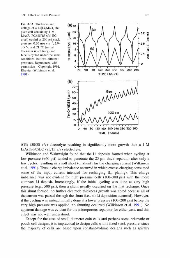
(G3) (50/50 v/v) electrolyte resulting in significantly more growth than a 1 MLiAsF6-PC/EC (85/15 v/v) electrolyte.
Wilkinson and Wainwright found that the Li deposits formed when cycling atlow pressure (<60 psi) tended to penetrate the 25 µm thick separator after only afew cycles, resulting in a soft short (or shunt) for the charging current (Wilkinsonet al. 1991). Thus, a charge imbalance occurred in which excess charging consumedsome of the input current intended for recharging (Li plating). This chargeimbalance was not evident for high pressure cells (100–300 psi) with the morecompact Li deposit. Interestingly, if the initial cycling was done at very highpressure (e.g., 500 psi), then a shunt usually occurred on the first recharge. Oncethis shunt formed, no further electrode thickness growth was noted because all ofthe current was passed through the shunt (i.e., no Li deposition occurred). However,if the cycling was instead initially done at a lower pressure (100–200 psi) before thevery high pressure was applied, no shunting occurred (Wilkinson et al. 1991). Noapparent damage was evident for the microporous separator for either case, and thiseffect was not well understood.
Except for the case of small diameter coin cells and perhaps some prismatic orpouch cell designs, it is impractical to design cells with a fixed stack pressure, sincethe majority of cells are based upon constant-volume designs such as spirally
Fig. 3.53 Thickness andvoltage of a Li||LixMoO2 flatplate cell containing 1 MLiAsF6-PC/(85/15 v/v) EC:a cell cycled at 200 psi stackpressure, 0.30 mA cm−2, 2.0–3.5 V, and 21 °C (initialthickness is arbitrary) andb cells cycled under the sameconditions, but two differentpressures. Reproduced withpermission—Copyright 1991,Elsevier (Wilkinson et al.1991)
3.9 Effect of Stack Pressure 125

wound cylindrical cells. For such cells, however, the Li layer growth during cyclingwill eventually build up the pressure, but the porous (dendritic) Li plating thatinitially occurs at lower pressure during the initial cycling may create detrimentaleffects for the subsequent cycling (Wilkinson et al. 1991). In addition, the pressuremay vary significantly within the cell as a function of radius. Electrode stackpressures greater than 1000 psi have been found at the core of spirally wound AAsize cells, which resulted in separator damage after long-term cycling (Wainwrightand Shimizu 1991). This affects all of the cell components. For example, althoughCelgard 2500 is a very incompressible polymer membrane, a wide disparity wasfound in the thickness and Gurley values (Arora and Zhang 2004) (i.e., air per-meability) after cell cycling (Wainwright and Shimizu 1991). The electrode pres-sure can be controlled to some extent by regulating the foil tensions and adjustingthe fit of the electrode assembly within the cell can, and this, in turn, is a deter-minant for the morphology of the plated Li metal during charging (Wilkinson et al.1991). It is also possible that pressure differentials within such batteries result in Liredistribution during cycling, which would greatly affect the cycling performanceand life of the cell (Ferrese and Newman 2014). The application of force to improvethe electrochemical performance has been patented (Scordilis-Kelley et al. 2015).
3.10 Summary
The Li cycling CE is strongly dependent upon the Li morphology, which is gov-erned in large part by the SEI composition. The SEI is typically a multilayerstructure on the surface of the Li, with the species abutting the Li being the mostreduced, and those close to the electrolyte interface often having organic con-stituents. Additives/impurities are typically the most reactive electrolyte compo-nents and are thus reduced before other SEI components. Thus, even ppm amountsof species such as H2O, O2, and CO2 can drastically change the SEI. Solventreduction species are often prominent for reactive solvents (e.g., esters and car-bonates), while anion reactions can be more influential when more stable solvents(e.g., ethers) are present. The electrolyte salt concentration can have a major impacton the CE for highly concentrated electrolytes, but this is strongly influenced by thesolvent and Li salt employed. The replacement of aprotic solvents with ILs reduces,but does not fully prevent, formation of Li dendrites. ILs (and inorganic fillers) mayalso be added to SPEs to improve their Li plating/stripping attributes and reduce thetendency for dendrites to form. Block copolymer electrolytes consisting of poly-styrene and poly(ethylene oxide) have been extensively evaluated in an effort toprevent dendrite growth through these rigid electrolytes. While these do hinderdendrite infiltration, they do not ultimately prevent short-circuiting of cells due todendrites. This is also the case for solid inorganic (crystalline or glassy) separators.
The reactivity of Li with electrolyte components leading to SEI formation resultsin significant differences in the Li electrodeposition morphology from that of othermetals. Rather than forming tree-like dendrites, Li tends to instead form either
126 3 High Coulombic Efficiency of Lithium Plating/Stripping …

kinked needles (one-dimensional growth) and/or nodules (three-dimensionalgrowth). Branching of the needles and/or aggregation of the needles/nodulesleads to more complicated constructs that are often also referred to as dendrites. Thesubstrate on which the Li is plated is a significant factor governing the deposition.Reactivity with electrolyte components (including impurities) leads to organic,inorganic (salt), and metal oxide surface film formation, which influences (andpossibly dominates) ion transport to and reactivity with the deposition surfaces.Substrate surface roughness (pits, ridge lines, etc.) also dramatically affects whereand how Li deposits. For some metal substrates, alloy formation further complicatesthe interpretation of the electrochemical redox reactions occurring. The reactionconditions (pulsed plating, plated charge, and plating/stripping current density), aswell as aging (storage) of the deposited Li, affect not only the deposition mor-phology, but also the amount of Li that may be electrochemically stripped due tocontinuous electrochemical/chemical side reactions that result in dead (electro-chemically inaccessible) Li—the extent of which is often dictated by the surfacearea and exposure time between the deposited Li and electrolyte. This, in turn,creates the highly resistive interphasial (mossy) Li layer that typically builds up onthe Li surface after repeated cycling. This layer—rather than short-circuiting fromLi dendrites—is often what limits the cell capacity and lifetime of cells using Limetal anodes. Plating at elevated temperature tends to facilitate three-dimensionalgrowth of the Li deposits, whereas plating at subambient temperature often resultsinstead in one-dimensional growth. Finally, the application of stack pressure gen-erally results in compression of the Li deposit and superior plating/strippingbehavior due to both lower side reaction rates (with the less porous Li) and lessdead Li due to better electrical contact within the deposited Li.
References
Abraham KM (1985) Recent developments in secondary lithium battery technology. J Power Sour14:179–191
Abraham KM, Goldman JL (1983) The use of the reactive ether, Tetrahydrofuran (THF), inrechargeable lithium cells. J Power Sour 9:239–245
Abraham KM, Goldman JL, Natwig DL (1982) Characterization of ether electrolytes forrechargeable lithium cells. J Electrochem Soc 129(11):2404–2409
Abraham KM, Foos JS, Goldman JL (1984) Long cycle life secondary lithium cells utilizingtetrahydrofuran. J Electrochem Soc 131(9):2197–2199
Abraham KM, Pasquariello DM, Martin FJ (1986) Mixed ether electrolytes for secondary lithiumbatteries with improved low temperature performance. J Electrochem Soc 133(4):661–666
Appetecchi GB, Passerini S (2002) Poly(ethylene oxide)-LiN(SO2CF2CF3)2 polymer elec-trolytes. J Electrochem Soc 149(7):A891–A897. doi:10.1149/1.1483098
Appetecchi GB, Croce F, Dautzenberq G, Mastragostino M, Ronci F, Scrosati B, Soavi F,Zanelli A, Alessandrini F, Prosini PP (1998) Composite polymer electrolytes with improvedlithium metal electrode interfacial properties I. Electrochemical properties of dry PEO-LiXsystems. J Electrochem Soc 145(12):4126–4132
3.10 Summary 127

Appetecchi GB, Croce F, Ronci F, Scrosati B, Alessandrini F, Carewska M, Prosini PP (1999)Electrochemical characterization of a composite polymer electrolyte with improved lithiummetal electrode interfacial properties. Ionics 5:59–63
Appetecchi GB, Scaccia S, Passerini S (2000) Investigation on the stability of the lithium-polymerelectrolyte interface. J Electrochem Soc 147(12):4448–4452
Appetecchi GB, Kim GT, Montanino M, Carewska M, Marcilla R, Mecerreyes D, De Meatza I(2010) Ternary polymer electrolytes containing pyrrolidinium-based polymeric ionic liquidsfor lithium batteries. J Power Sour 195(11):3668–3675. doi:10.1016/j.jpowsour.2009.11.146
Appetecchi GB, Kim GT, Montanino M, Alessandrini F, Passerini S (2011) Room temperaturelithium polymer batteries based on ionic liquids. J Power Sour 196(16):6703–6709. doi:10.1016/j.jpowsour.2010.11.070
Arakawa M, Tobishima S-I, Nemoto Y, Ichimura M (1993) Lithium electrode cycleability andmorphology dependence on current density. J Power Sour 43–44:27–35
Arakawa M, Tobishima S, Hirai T, Yamaki J (1999) Effect of purification of2-Methyltetrahydrofuran/Ethylene carbonate mixed solvent electrolytes on cyclability oflithium metal anodes for rechargeable cells. J Appl Electrochem 29:1191–1196
Arie AA, Lee JK (2011) Electrochemical characteristics of lithium metal anodes with diamond likecarbon film coating layer. Diam Relat Mater 20(3):403–408. doi:10.1016/j.diamond.2011.01.040
Armstrong RD, Brown OR, Ram RP, Tuck CD (1989) Lithium electrodes based upon aluminumand alloy substrates i. impedance measurements on aluminum. J Power Sour 28:259–267
Arora P, Zhang Z (2004) Battery separators. Chem Rev 104:4419–4462Aurbach D (1989a) The electrochemical behavior of lithium salt solutions of c-butyrolactone with
noble metal electrodes. J Electrochem Soc 136(4):906–913Aurbach D (1989b) Identification of surface films formed on lithium surfaces in c-butyrolactone
solutions. 1. uncontaminated solutions. J Electrochem Soc 136(6):1606–1610Aurbach D (1999) The electrochemical behavior of active metal electrodes in nonaqueous
solutions. Nonaqueous Electrochem (Ed Aurbach, D):289–411Aurbach D, Chusid (Youngman) O (1993) In situ FTIR spectroelectrochemical studies of surface
films formed on Li and nonactive electrodes at low potentials in Li salt solutions containingCO2. J Electrochem Soc 140 (11):L155–L157
Aurbach D, Gofer Y (1991) The behavior of lithium electrodes in mixtures of alkyl carbonates andethers. J Electrochem Soc 138(12):3529–3536
Aurbach D, Gottlieb H (1989) The electrochemical behavior of selected polar aprotic solvents.Electrochim Acta 34(2):141–156
Aurbach D, Granot E (1997) The study of electrolyte solutions based on solvents from the“Glyme” family (linear polyethers) for secondary Li battery systems. Electrochim Acta 42(4):697–718
Aurbach D, Moshkovich M (1998) A study of lithium deposition-dissolution processes in a fewselected electrolyte solutions by electrochemical quartz crystal microbalance. J ElectrochemSoc 145(8):2629–2639
Aurbach D, Daroux ML, Faguy PW, Yeager E (1987) Identification of surface films formed onlithium in propylene carbonate solutions. J Electrochem Soc 134(7):1611–1620
Aurbach D, Daroux ML, Faguy PW, Yeager E (1988) Identification of surface films formed onlithium in dimethoxyethane and tetrahydrofuran solutions. J Electrochem Soc 135(8):1863–1871
Aurbach D, Gofer Y, Langzam J (1989) The correlation between surface chemistry, surfacemorphology, and cycling efficiency of lithium electrodes in a few polar aprotic systems.J Electrochem Soc 136(11):3198–3205
Aurbach D, Youngman O, Dan P (1990a) The electrochemical behavior of 1,3-Dioxolane-LiClO4
solutions—II Contaminated solutions. Electrochim Acta 35(3):639–655Aurbach D, Youngman O, Gofer Y, Meitav A (1990b) The electrochemical behavior of
1,3-Dioxolane-LiClO4 solutions—I. Uncontaminated solutions. Electrochim Acta 35(3):625–638
128 3 High Coulombic Efficiency of Lithium Plating/Stripping …

Aurbach D, Skaletsky R, Gofer Y (1991a) The electrochemical behavior of calcium electrodes in afew organic electrolytes. J Electrochem Soc 138(12):3536–3545
Aurbach D, Daroux M, Faguy P, Yeager E (1991b) The electrochemistry of noble metal electrodesin aprotic organic solvents containing lithium salts. J Electroanal Chem 297:225–244
Aurbach D, Gofer Y, Ben-Zion M, Aped P (1992) The behaviour of lithium electrodes inpropylene and ethylene carbonate: the major factors that influence Li cycling efficiency.J Electroanal Chem 339:451–471. doi:http://dx.doi.org/10.1016/0022-0728(92)80467-I
Aurbach D, Daroux M, McDougall G, Yeager EB (1993) Spectroscopic studies of lithium in anultrahigh vacuum system. J Electroanal Chem 358:63–76. doi:http://dx.doi.org/10.1016/0022-0728(93)80431-G
Aurbach D, Ein-Ely Y, Zaban A (1994a) The surface chemistry of lithium electrodes in alkylcarbonate solutions. J Electrochem Soc 141(1):L1–L3
Aurbach D, Weissman I, Zaban A, Chusid O (1994b) Correlation between surface chemistry,morphology, cycling efficiency and interfacial properties of Li electrodes in solutionscontaining different Li salts. Electrochim Acta 39:51–71
Aurbach D, Zaban A, Gofer Y, Abramson O, Ben-Zion M (1995a) Studies of Li anodes in theelectrolyte system 2Me-THF/THF/Me-Furan/LiAsF6. J Electrochem Soc 142(3):687–696
Aurbach D, Zaban A, Schechter A, Ein-Eli Y, Zinigrad E, Markovsky B (1995b) The study ofelectrolyte solutions based on ethylene and diethyl carbonates for rechargeable Li Batteries.I. Li metal anodes. J Electrochem Soc 142(9):2873–2882
Aurbach D, Zaban A, Gofer Y, Ely YE, Weissman I, Chusid O, Abramson O (1995c) Recentstudies of the lithium-liquid electrolyte interface. Electrochemical, morphological and spectralstudies of a few important systems. J Power Sour 54:76–84
Aurbach D, Markovsky B, Shechter A, Ein-Eli Y (1996) A comparative study of synthetic graphiteand Li electrodes in electrolyte solutions based on ethylene carbonate-dimethyl carbonatemixtures. J Electrochem Soc 143(12):3809–3820
Aurbach D, Zaban A, Ein-Eli Y, Weissman I, Chusid O, Markovsky B, Levi M, Levi E,Schechter A, Granot E (1997) Recent studies on the correlation between surface chemistry,morphology, three-dimensional structures and performance of Li and Li-C intercalation anodesin several important electrolyte systems. J Power Sour 68:91–98
Aurbach D, Zinigrad E, Teller H, Dan P (2000) Factors which limit the cycle life of rechargeablelithium (metal) batteries. J Electrochem Soc 147:1274–1279
Aurbach D, Zinigrad E, Cohen Y, Teller H (2002a) A short review of failure mechanisms oflithium metal and lithiated graphite anodes in liquid electrolyte solutions. Solid State Ionics148:405–416
Aurbach D, Zinigrad E, Teller H, Cohen Y, Salitra G, Yamin H, Dan P, Elster E (2002b) Attemptsto improve the behavior of Li electrodes in rechargeable lithium batteries. J Electrochem Soc149 (10):A1267–A1277. doi:10.1149/1.1502684
Baek S-W, Lee J-M, Kim TY, Song M-S, Park Y (2014) Garnet related lithium ion conductorprocessed by spark plasma sintering for all solid state batteries. J Power Sour 249:197–206.doi:10.1016/j.jpowsour.2013.10.089
Bailey DM, Skelton WH, Smith JF (1979) Lithium-Tin phase relationship between Li7Sn2 andLiSn. J Less-Common Metal 64:233–240
Balducci A, Jeong SS, Kim GT, Passerini S, Winter M, Schmuck M, Appetecchi GB, Marcilla R,Mecerreyes D, Barsukov V, Khomenko V, Cantero I, De Meatza I, Holzapfel M, Tran N(2011) Development of safe, green and high performance ionic liquids-based batteries(ILLIBATT Project). J Power Sour 196 (22):9719–9730. doi:10.1016/j.jpowsour.2011.07.058
Bale CW (1989a) The Li–Rb (Lithium–Rubidium) system. Bull Alloy Phase Diag 10(3):268–269Bale CW (1989b) The Cs–Li (Cesium–Lithium) system. Bull Alloy Phase Diag 10(3):232–233Bale CW (1989c) The Li–Na (Lithium–Sodium) system. Bull Alloy Phase Diag 10(3):265–268Bale CW (1989d) The Li–Ti (Lithium–Titanium) system. Bull Alloy Phase Diag 10(2):135–138Baretzky B, Eckstein W, Schorn RP (1995) Cu/Li Alloys: conditions for their application in fusion
reactors—focussing on the interaction of segregation and sputtering phenomena. J Nucl Mater224:50–70
References 129

Basile A, Hollenkamp AF, Bhatt AI, O’Mullane AP (2013) Extensive charge–discharge cycling oflithium metal electrodes achieved using ionic liquid electrolytes. Electrochem Commun 27:69–72. doi:10.1016/j.elecom.2012.10.030
Bates JB (1994) Protective lithium ion conducting ceramic coating for lithium metal anodes andassociate method. USA Patent 5,314,765, 24 May 1994
Bates JB, Dudney NJ, Gruzalski GR, Zuhr RA, Choudhury A, Luck CF, Robertson JD (1993)Fabrication and Characterization of Amorphous Lithium Electrolyte Thin-Films andRechargeable Thin-Film Batteries. J Power Sour 43(1–3):103–110. doi:10.1016/0378-7753(93)80106-y
Belov DG, Yarmolenko OV, Peng A, Efimov ON (2006) Lithium surface protection bypolyacetylene in situ polymerization. Syn Metals 156(9–10):745–751. doi:10.1016/j.synthmet.2006.04.006
Besenhard JO (1977) The effect of I-anions on Li cycling in propylene carbonate. J ElectroanalChem 78:189–193
Besenhard JO (1978) Cycling behaviour and corrosion of Li–Al electrodes in organic electrolytes.J Electroanal Chem 1978(94):77–81
Besenhard JO, Eichinger G (1976) High energy density lithium cells. Part I. Electrolytes andanodes. J Electroanal Chem 68:1–18
Besenhard JO, Fritz HP, Wudy E, Dietz K, Meyer H (1985) Cycling of b-LiAl in organicelectrolytes—effect of electrode contaminants and electrolyte additives. J Power Sour 14:193–200
Besenhard JO, Hess M, Komenda P (1990) Dimensionally stable Li-alloy electrodes for secondarybatteries. Solid State Ionics 40(41):525–529
Besenhard JO, Wagner MW, Winter M, Jannakoudakis AD, Jannakoudakis PD, Theodoridou E(1993) Inorganic film-forming electrolyte additives improving the cycling behaviour ofmetallic lithium electrodes and the self-discharge of carbon—lithium electrodes. J Power Sour44:413–420. doi:http://dx.doi.org/10.1016/0378-7753(93)80183-P
Best AS, Bhatt AI, Hollenkamp AF (2010) Ionic liquids with the Bis(fluorosulfonyl)imide anion:electrochemical properties and applications in battery technology. J Electrochem Soc 157 (8):A903–A911. doi:10.1149/1.3429886
Bhatt AI, Best AS, Huang J, Hollenkamp AF (2010) Application of theN-Propyl-N-methyl-pyrrolidinium Bis(fluorosulfonyl)imide RTIL containing lithium Bis(fluorosulfonyl)imide in ionic liquid based lithium batteries. J Electrochem Soc 157 (1):A66–A74. doi:10.1149/1.3257978
Bhatt AI, Kao P, Best AS, Hollenkamp AF (2012) Towards Li-air and Li-S batteries:understanding the morphological changes of lithium surfaces during cycling at a range ofcurrent densities in an ionic liquid electrolyte. ECS Trans 50(11):383–401
Bieker G, Winter M, Bieker P (2015) Electrochemical In situ investigations of SEI and dendriteformation on the lithium metal anode. Phys Chem Chem Phys 17 (14):8670–8679. doi:10.1039/c4cp05865h
Bouchet R (2014) A stable lithium metal interface. Nat Nanotechnol 9:572–573Brissot C, Rosso M, Chazalviel JN, Baudry P, Lascaud S (1998) In situ study of dendritic growth
in lithium/PEO-salt/lithium cells. Electrochim Acta 43(10–11):1569–1574Brissot C, Rosso M, Chazalviel J-N, Lascaud S (1999a) Dendritic growth mechanisms in
lithium/polymer cells. J Power Sour 81–82:925–929Brissot C, Rosso M, Chazalviel J-N, Lascaud S (1999b) In situ concentration cartography in the
neighborhood of dendrites growing in lithium/polymer-electrolyte/lithium cells. J ElectrochemSoc 146(12):4393–4400
Bronger W, Nacken B, Ploog K (1975) Zur Synthese und Struktur von Li2Pt und LiPt.J Less-Common Metals 43:143–146
Bronger W, Klessen G, Müller P (1985) Zur Struktur von LiPt7. J Less-Common Metals 109:L1–L2
130 3 High Coulombic Efficiency of Lithium Plating/Stripping …
Budi A, Basile A, Opletal G, Hollenkamp AF, Best AS, Rees RJ, Bhatt AI, O’Mullane AP,Russo SP (2012) Study of the initial stage of solid electrolyte interphase formation uponchemical reaction of lithium metal and N-methyl-N-propyl-pyrrolidinium-Bis(Fluorosulfonyl)Imide. J Phys Chem C 116 (37):19789–19797. doi:10.1021/jp304581g
Camurri C, Ortiz M, Carrasco C (2003) Hot consolidation of Cu–Li powder alloys: a first approachto characterization. Mater Charact 51 (2–3):171–176. doi:10.1016/j.matchar.2003.11.002
Cao C, Li Z-B, Wang X-L, Zhao X-B, Han W-Q (2014) Recent advances in inorganic solidelectrolytes for lithium batteries. Front Energy Res 2:1–10. doi:10.3389/fenrg.2014.00025
Carpio RA, King LA (1981) Deposition and dissolution of lithium–aluminum alloy and aluminumfrom chloride-saturated LiCl–AlCl and NaCl–AlCl melts. J Electrochem Soc 128(7):1510–1517
Chang S-G, Lee HJ, Kang HY, Park S-M (2001) Characterization of surface films formed prior tobulk reduction of lithium in rigorously dried propylene carbonate solutions. Bull Korean ChemSoc 22(5):481–487
Chang HJ, Trease NM, Ilott AJ, Zeng D, Du L-S, Jerschow A, Grey CP (2015) Investigating Limicrostructure formation on Li anodes for lithium batteries by in situ 6Li/7Li NMR and SEM.J Phys Chem C 119 (29):16443–16451. doi:10.1021/acs.jpcc.5b03396
Cheng H, Zhu C, Huang B, Lu M, Yang Y (2007) Synthesis and electrochemical characterizationof PEO-based polymer electrolytes with room temperature ionic liquids. Electrochim Acta 52(19):5789–5794. doi:10.1016/j.electacta.2007.02.062
Cheng L, Crumlin EJ, Chen W, Qiao R, Hou H, Franz Lux S, Zorba V, Russo R, Kostecki R,Liu Z, Persson K, Yang W, Cabana J, Richardson T, Chen G, Doeff M (2014) The origin ofhigh electrolyte-electrode interfacial resistances in lithium cells containing garnet type solidelectrolytes. Phys Chem Chem Phys 16 (34):18294–18300. doi:10.1039/c4cp02921f
Cheng L, Chen W, Kunz M, Persson K, Tamura N, Chen GY, Doeff M (2015a) Effect of surfacemicrostructure on electrochemical performance of garnet solid electrolytes. Acs Appl MaterInter 7 (3):2073–2081. doi:10.1021/am508111r
Choi N-S, Lee Y-M, Park J-H, Park J-K (2003) Interfacial enhancement between lithium electrodeand polymer electrolytes. J Power Sour 119–121:610-616. doi:10.1016/s0378-7753(03)00305-7
Choi N-S, Lee YM, Cho KY, Ko D-H, Park J-K (2004a) Protective layer with Oligo(ethyleneglycol) Borate anion receptor for lithium metal electrode stabilization. Electrochem Commun 6(12):1238–1242. doi:10.1016/j.elecom.2004.09.023
Choi N-S, Lee YM, Seol W, Lee JA, Park J-K (2004b) Protective coating of lithium metalelectrode for interfacial enhancement with gel polymer electrolyte. Solid State Ionics 172 (1–4):19–24. doi:10.1016/j.ssi.2004.05.008
Choi J-W, Kim J-K, Cheruvally G, Ahn J-H, Ahn H-J, Kim K-W (2007a) Rechargeablelithium/sulfur battery with suitable mixed liquid electrolytes. Electrochim Acta 52 (5):2075–2082. doi:10.1016/j.electacta.2006.08.016
Choi J, Cheruvally G, Kim Y, Kim J, Manuel J, Raghavan P, Ahn J, Kim K, Ahn H, Choi D(2007b) Poly(ethylene oxide)-based polymer electrolyte incorporating room-temperature ionicliquid for lithium batteries. Solid State Ionics 178 (19–20):1235–1241. doi:10.1016/j.ssi.2007.06.006
Choi J-W, Cheruvally G, Kim D-S, Ahn J-H, Kim K-W, Ahn H-J (2008) rechargeablelithium/sulfur battery with liquid electrolytes containing toluene as additive. J Power Sour 183(1):441–445. doi:10.1016/j.jpowsour.2008.05.038
Choi N-S, Koo B, Yeon J-T, Lee KT, Kim D-W (2011) Effect of a novel amphipathic ionic liquidon lithium deposition in gel polymer electrolytes. Electrochim Acta 56 (21):7249–7255.doi:10.1016/j.electacta.2011.06.058
Choi SM, Kang IS, Sun Y-K, Song J-H, Chung S-M, Kim D-W (2013) Cycling characteristics oflithium metal batteries assembled with a surface modified lithium electrode. J Power Sour244:363–368. doi:10.1016/j.jpowsour.2012.12.106
References 131

Christensen J, Albertus P, Sanchez-Carrera RS, Lohmann T, Kozinsky B, Liedtke R, Ahmed J,Kojic A (2012) A critical review of Li/Air batteries. J Electrochem Soc 159 (2):R1–R30.doi:10.1149/2.086202jes
Chung K-I, Lee J-D, Kim E-J, Kim W-S, Cho J-H, Choi Y-K (2003) Studies on the effects ofcoated Li2CO3 on lithium electrode. Microchem J 75 (2):71–77. doi:10.1016/s0026-265x(03)00026-2
Chung JH, Kim WS, Yoon WY, Min SW, Cho BW (2006) Electrolyte loss and dimensionalchange of the negative electrode in li powder secondary cell. J Power Sour 163 (1):191–195.doi:10.1016/j.jpowsour.2005.12.064
Dampier FW, Brummer SB (1977) The cycling behavior of the lithium electrode in LiAsF6/methylacetate solutions. Electrochim Acta 22:1339–1345
Dan P, Mengeritsky E, Aurbach D, Weissman I, Zinigrad E (1997) More details on the newLiMnO2 rechargeable battery technology developed at Tadiran. J Power Sour 68:443–447
de Vries H, Jeong S, Passerini S (2015) Ternary polymer electrolytes incorporatingpyrrolidinium-imide ionic liquids. RSC Adv 5(18):13598–13606. doi:10.1039/c4ra16070c
Débart A, Dupont L, Poizot P, Leriche JB, Tarascon JM (2001) A transmission electronmicroscopy study of the reactivity mechanism of tailor-made CuO particles toward lithium.J Electrochem Soc 148 (11):A1266–A1274. doi:10.1149/1.1409971
Devaux D, Harry KJ, Parkinson DY, Yuan R, Hallinan DT, MacDowell AA, Balsara NP (2015a)Failure mode of lithium metal batteries with a block copolymer electrolyte analyzed by X-raymicrotomography. J Electrochem Soc 162 (7):A1301–A1309. doi:10.1149/2.0721507jes
Devaux D, Glé D, Phan TNT, Gigmes D, Giroud E, Deschamps M, Denoyel R, Bouchet R(2015b) Optimization of block copolymer electrolytes for lithium metal batteries. Chem Mater27 (13):4682–4692. doi:10.1021/acs.chemmater.5b01273
Dey AN (1971) Electrochemical alloying of lithium in organic electrolytes. J Electrochem Soc 118(10):1547–1549
Dey AN (1977) Lithium anode film and organic and inorganic electrolyte batteries. Thin SolidFilms 43:131–171
Ding F, Xu W, Chen X, Zhang J, Engelhard MH, Zhang Y, Johnson BR, Crum JV, Blake TA,Liu X, Zhang JG (2013a) Effects of carbonate solvents and lithium salts on morphology andcoulombic efficiency of lithium electrode. J Electrochem Soc 160 (10):A1894–A1901. doi:10.1149/2.100310jes
Ding F, Xu W, Graff GL, Zhang J, Sushko ML, Chen X, Shao Y, Engelhard MH, Nie Z, Xiao J,Liu X, Sushko PV, Liu J, Zhang J-G (2013b) Dendrite-free lithium deposition via self-healingelectrostatic shield mechanism. J Am Chem Soc 135 (11):4450–4456. doi:10.1021/ja312241y
Dollé M, Sannier L, Beaudoin B, Trentin M, Tarascon J-M (2002) Live scanning electronmicroscope observations of dendritic growth in lithium/polymer cells. Electrochem Solid-StateLett 5 (12):A286–A289. doi:10.1149/1.1519970
Dominey LA, Goldman JL (1990) The improvement of rechargeable lithium battery electrolyteperformance with additives. In: Proceedings of the 34th international power sourcessymposium 25 Jun 1990–28 Jun 1990, pp 84–86. doi:10.1109/IPSS.1990.145797
Dominey LA, Goldman JL, Koch VR, Shen D, Subbarao S, Huang CK, Halpert G, Deligiannis F(1991) Improved lithium/titanium disulfide cell cycling in either-based electrolytes withsynergistic additives: part II. Proposed chemical pathways contributing to improved cycling.In: Abraham, KM, Salomon, M (eds) Proceedings of the symposium on primary and secondarylithium batteries. The Electrochem Soc Inc PV 91–3:293–301
Du F, Zhao N, Li Y, Chen C, Liu Z, Guo X (2015) All solid state lithium batteries based onlamellar garnet-type ceramic electrolytes. J Power Sour 300:24–28. doi:10.1016/j.jpowsour.2015.09.061
Dudley JT, Wilkinson DP, Thomas G, LeVae R, Woo S, Blom H, Horvath C, Juzkow MW,Denis B, Juric P, Aghakian P, Dahn JR (1991) Conductivity of electrolytes for rechargeablelithium batteries. J Power Sourc 35:59–82
Dudney NJ (2005) Solid-state thin-film rechargeable batteries. Mater Sci Eng B 116:245–249
132 3 High Coulombic Efficiency of Lithium Plating/Stripping …

Ebner WB, Lin HW (1987) Prototype rechargeable lithium batteries. US government reportNSWC TR 86–108
Edström K, Herstedt M, Abraham DP (2006) A new look at the solid electrolyte interphase ongraphite anodes in Li–Ion batteries. J Power Sour 153 (2):380–384. doi:10.1016/j.jpowsour.2005.05.062
Ein Ely Y, Aurbach D (1992) Identification of surface films formed on active metals and nonactivemetal electrodes at low potentials in methyl formate solutions. Langmuir 8:1845–1850
Ein-Eli Y, Aurbach D (1996) The correlation between the cycling efficiency, surface chemistry andmorphology of Li electrodes in electrolyte solutions based on methyl formate. J Power Sour54:281–288
Ein-Eli Y, Thomas SR, Koch VR, Aurbach D, Markovsky B, Schechter A (1996)Ethylmethylcarbonate, a promising solvent for Li-Ion rechargeable batteries. J ElectrochemSoc 143(12):L273–L277
Ein-Eli Y, McDevitt SF, Aurbach D, Markovsky B, Schechter A (1997) Methyl propyl carbonate:a promising single solvent for Li-ion battery electrolytes. J Electrochem Soc 144(7):L180–L184
Eweka E, Owen JR, Ritchie A (1997) Electrolytes and additives for high efficiency lithiumcycling. J Power Sour 65:247–251
Fauteux D (1993) Lithium electrode in polymer electrolytes. Electrochim Acta 38(9):1199–1210Fergus JW (2010) Ceramic and polymeric solid electrolytes for lithium-ion batteries. J Power Sour
195 (15):4554–4569. doi:10.1016/j.jpowsour.2010.01.076Fernicola A, Croce F, Scrosati B, Watanabe T, Ohno H (2007) LiTFSI-BEPyTFSI as an improved
ionic liquid electrolyte for rechargeable lithium batteries. J Power Sour 174 (1):342–348.doi:10.1016/j.jpowsour.2007.09.013
Ferrese A, Newman J (2014) Mechanical deformation of a lithium-metal anode due to a very stiffseparator. J Electrochem Soc 161 (9):A1350–A1359. doi:10.1149/2.0911409jes
Fischer AK, Vissers DR (1983) Morphological studies on the Li–Al electrode in fused saltelectrolytes. J Electrochem Soc 130(1):5–11
Frazer EJ (1981) Electrochemical formation of Lithium–Aluminium alloys in propylene carbonateelectrolytes. J Electroanal Chem 121:329–339
Fu J (1997a) Lithium ion conductive glass-ceramics. USA Patent 5,702,995, 30 Dec 1997Fu J (1997b) Superionic conductivity of glass-ceramics in the system Li2O-Al2O3-TiO2-P2O5.
Solid State Ionics 96 (3–4):195–200. doi:10.1016/s0167-2738(97)00018-0Fujieda T, Yamamoto N, Saito K, Ishibashi T, Honjo M, Koike S, Wakabayashi N, Higuchi S
(1994) Surface of lithium electrodes prepared in Ar + CO2 gas. J Power Sour 52:197–200. doi:http://dx.doi.org/10.1016/0378-7753(94)01961-4
Fujieda T, Koike S, Higuchi S (1998) Influence of water and other contaminants in electrolytesolutions on lithium electrodeposition. Mat Res Soc Symp Proc 496:463–468
Fung YS, Lai HC (1989) Cyclic chronopotentiometric studies of the LiAl anode in methyl acetate.J Appl Electrochem 19:239–246
Furuya R, Tachikawa N, Yoshii K, Katayama Y, Miura T (2015) Deposition and dissolution oflithium through lithium phosphorus oxynitride thin film in some ionic liquids. J ElectrochemSoc 162 (9):H634–H637. doi:10.1149/2.0471509jes
Gachot G, Grugeon S, Armand M, Pilard S, Guenot P, Tarascon J-M, Laruelle S (2008)Deciphering the multi-step degradation mechanisms of carbonate-based electrolyte in Libatteries. J Power Sour 178 (1):409–421. doi:10.1016/j.jpowsour.2007.11.110
Gan H, Takeuchi ES (1996) Lithium electrodes with and without CO2 treatment: electrochemicalbehavior and effect on high rate lithium battery performance. J Power Sour 62:45–50
Gao XP, Bao JL, Pan GL, Zhu HY, Huang PX, Wu F, Song DY (2004) Preparation andelectrochemical performance of polycrystalline and single crystalline CuO nanorods as anodematerials for Li Ion battery. J Phys Chem B 108:5547–5551
Garreau M, Thevenin J, Fekir M (1983) On the processes responsible for the degradation of theAluminum–Lithium electrode used as anode material in lithium aprotic electrolyte batteries.J Power Sour 9:235–238
References 133
Gąsior W, Onderka B, Moser Z, Dębski A, Gancarz T (2009) Thermodynamic evaluation of Cu–Li phase diagram from EMF measurements and DTA study. Calphad 33 (1):215–220. doi:10.1016/j.calphad.2008.10.006
Gasparotto LH, Borisenko N, Bocchi N, El Abedin SZ, Endres F (2009) In situ STM investigationof the lithium underpotential deposition on Au(111) in the air- and water-stable ionic liquid1-Butyl-1-methylpyrrolidinium Bis(trifluoromethylsulfonyl)amide. Phys Chem Chem Phys 11(47):11140–11145. doi:10.1039/b916809e
Gauthier M, Fauteux D, Vassort G, Bélanger A, Duval M, Ricoux P, Chabagno J-M, Muller D,Rigaud P, Armand MB, Deroo D (1985a) Assessment of polymer-electrolyte batteries for EVand ambient temperature applications. J Electrochem Soc 132(6):1333–1340
Gauthier M, Fauteux D, Vassort G, Belanger A, Duval M, Ricoux P, Chabagno J-M, Muller D,Rigaud P, Armand MB, Deroo D (1985b) Behavior of polymer electrolyte batteries at 80–100 °C and near room temperature. J Power Sour 14:23–26
Geronov Y, Schwager F, Muller RH (1982) Electrochemical studies of the film formation onlithium in propylene carbonate solutions under open-circuit conditions. J Electrochem Soc 129(7):1422–1429
Geronov Y, Zlatilova P, Moshtev RV (1984a) The secondary lithium-aluminum electrode at roomtemeperature. I. Cycling in LiClO4-propylene carbonate solutions. J Power Sour 12:145–153
Geronov Y, Zlatilova P, Staikov G (1984b) Electrochemical nucleation and growth of b-LiAlAlloy in aprotic electrolyte solutions. Electrochim Acta 29(4):551–555
Geronov Y, Zlatilova P, Staikov G (1984c) The secondary Lithium–Aluminum electrode at roomtemperature. II. Kinetics of the electrochemical formation of the Lithium–Aluminum Alloy.J Power Sour 12:155–165
Geronov Y, Zlatilova P, Puresheva B, Pasquali M, Pistoia G (1989) Behaviour of the Lithiumelectrode during cycling in nonaqueous solutions. J Power Sour 26:585–591
Girard GM, Hilder M, Zhu H, Nucciarone D, Whitbread K, Zavorine S, Moser M, Forsyth M,MacFarlane DR, Howlett PC (2015) Electrochemical and physicochemical properties of smallphosphonium cation ionic liquid electrolytes with high lithium salt content. Phys Chem ChemPhys 17 (14):8706–8713. doi:10.1039/c5cp00205b
Gireaud L, Grugeon S, Laruelle S, Yrieix B, Tarascon JM (2006) Lithium metal stripping/platingmechanisms studies: a metallurgical approach. Electrochem Commun 8 (10):1639–1649.doi:10.1016/j.elecom.2006.07.037
Gofer Y, Ben-Zion M, Aurbach D (1992) Solutions of LiAsF6 in 1,3-Dioxolane for secondarylithium batteries. J Power Sour 39:163–178
Gofer Y, Barbour R, Luo Y, Tryk D, Scherson DA, Jayne J, Chottiner G (1995) Underpotentialdeposition of lithium on polycrystalline gold from a LiClO4/Poly(ethylene oxide) solidpolymer electrolyte in ultrahigh vacuum. J Phys Chem 99:11739–11741
Goldman JL, Mank RM, Young JH, Koch VR (1980) Structure-reactivity relationships ofmethylated tetrahydrofurans with lithium. J Electrochem Soc 127(7):1461–1467
Goldman JL, Dominey LA, Koch VR (1989) The stabilization of LiAsF6/1,3-Dioxolane for use inrechargeable lithium batteries. J Power Sour 26:519–523
Goodman JKS, Kohl PA (2014) Effect of alkali and alkaline earth metal salts on suppression oflithium dendrites. J Electrochem Soc 161 (9):D418–D424. doi:10.1149/2.0301409jes
Gorodyskii AV, Sazhin SV, Danilin VV, Kuksenko SP (1989) Effect of sodium cation on lithiumcorrosion in aprotic media. J Power Sour 28:335–343
Grugeon S, Laruelle S, Herrera-Urbina R, Dupont L, Poizot P, Tarascon JM (2001) Particle sizeeffects on the electrochemical performance of copper oxides toward lithium. J Electrochem Soc148 (4):A285–A292. doi:10.1149/1.1353566
Guo J, Wen Z, Wu M, Jin J, Liu Y (2015) Vinylene carbonate–LiNO3: a hybrid additive incarbonic ester electrolytes for SEI modification on Li metal anode. Electrochem Commun51:59–63. doi:10.1016/j.elecom.2014.12.008
134 3 High Coulombic Efficiency of Lithium Plating/Stripping …
Gurevitch I, Buonsanti R, Teran AA, Gludovatz B, Ritchie RO, Cabana J, Balsara NP (2013)Nanocomposites of titanium dioxide and polystyrene-Poly(ethylene oxide) block copolymer assolid-state electrolytes for lithium metal batteries. J Electrochem Soc 160 (9):A1611–A1617.doi:10.1149/2.117309jes
Hallinan DT, Mullin SA, Stone GM, Balsara NP (2013) Lithium metal stability in batteries withblock copolymer electrolytes. J Electrochem Soc 160 (3):A464–A470. doi:10.1149/2.030303jes
Halpert G, Surampudi S, Shen D, Huang C-K, Narayanan S, Vamos E, Perrone D (1994) Status ofthe development of rechargeable lithium cells. J Power Sour 47:287–294
Hamon Y, Brousse T, Jousse F, Topart P, Buvat P, Schleich DM (2001) Aluminum negativeelectrode in lithium ion batteries. J Power Sour 97–98:185–187
Henderson WA (2006) Glyme–Lithium salt phase behavior. J Phys Chem B 110:13177–13183Herbert EG, Tenhaeff WE, Dudney NJ, Pharr GM (2011) Mechanical characterization of LiPON
films using nanoindentation. Thin Solid Films 520 (1):413–418. doi:10.1016/j.tsf.2011.07.068Herlem G, Fahys B, Székely M, Sutter E, Mathieu C, Herlem M, Penneau J-F (1996) n-butylamine
as solvent for lithium salt electrolytes. Structure and properties of concentrated solutions.Electrochim Acta 41(17):2753–2760
Herr R (1990) Organic electrolytes for lithium cells. Electrochim Acta 35(8):1257–1265Hess S, Wohlfahrt-Mehrens M, Wachtler M (2015) Flammability of Li-Ion battery electrolytes:
flash point and self-extinguishing time measurements. J Electrochem Soc 162 (2):A3084–A3097. doi:10.1149/2.0121502jes
Hirai T, Yoshimatsu I, Yamaki J-I (1994a) Influence of electrolyte on lithium cycling efficiencywith pressurized electrode stack. J Electrochem Soc 141(3):611–614
Hirai T, Yoshimatsu I, Yamaki J-I (1994b) Effect of additives on lithium cycling efficiency.J Electrochem Soc 141(9):2300–2305
Honeywell I (1975) Lithium-organic electrolyte batteries for sensor and communicationsequipment. US Government report AD-A020 143
Hong S-T, Kim J-S, Lim S-J, Yoon WY (2004) Surface characterization of emulsified lithiumpowder electrode. Electrochim Acta 50 (2–3):535–539. doi:10.1016/j.electacta.2004.03.065
Howlett PC, MacFarlane DR, Hollenkamp AF (2004) High lithium metal cycling efficiency in aroom-temperature ionic liquid. Electrochem Solid-State Lett 7 (5):A97–A101. doi:10.1149/1.1664051
Howlett PC, Brack N, Hollenkamp AF, Forsyth M, MacFarlane DR (2006) Characterization of thelithium surface in N-methyl-N-alkylpyrrolidinium Bis(trifluoromethanesulfonyl)amideroom-temperature ionic liquid electrolytes. J Electrochem Soc 153 (3):A595–A606. doi:10.1149/1.2164726
Huang XH, Tu JP, Zhang B, Zhang CQ, Li Y, Yuan YF, Wu HM (2006) Electrochemicalproperties of NiO–Ni nanocomposite as anode material for lithium ion batteries. J Power Sour161 (1):541–544. doi:10.1016/j.jpowsour.2006.03.039
Huang XH, Tu JP, Xia XH, Wang XL, Xiang JY, Zhang L, Zhou Y (2009) Morphology effect onthe electrochemical performance of nio films as anodes for lithium ion batteries. J Power Sour188 (2):588–591. doi:10.1016/j.jpowsour.2008.11.111
Huggins RA (1988) Polyphase alloys as rechargeable electrodes in advanced battery systems.J Power Sour 22:341–350
Huggins RA (1989a) Materials science principles related to alloys of potential use in rechargeablelithium cells. J Power Sour 26(1–2):109–120
Huggins RH (1989b) Materials science principles related to alloys of potential use in rechargeablelithium cells. J Power Sour 26:109–120
Huggins RA (1999a) Lithium alloy negative electrodes. J Power Sour 81–82:13–19Huggins RA (1999b) Lithium alloy anodes in handbook of battery materials. Lithium Alloy
anodes in handbook of battery materials (Ed: Besenhard, J O) Wiley-VCH:359–381Huggins RA (2009) Lithium–Carbon alloys in advanced batteries-materials science aspects.
Lithium–Carbon Alloys in Advanced Batteries-Materials Science Aspects SpringerScience:127–149
References 135

Ichino T, Cahan BD, Scherson DA (1991) In situ attenuated total reflection fourier transforminfrared spectroscopy studies of the polyethylene Oxide/LiClO4-metallic lithium interface.J Electrochem Soc 138(11):L59–L61
Imanishi N, Hasegawa S, Zhang T, Hirano A, Takeda Y, Yamamoto O (2008) Lithium anode forlithium-air secondary batteries. J Power Sour 185 (2):1392–1397. doi:10.1016/j.jpowsour.2008.07.080
Ishiguro K, Nakata Y, Matsui M, Uechi I, Takeda Y, Yamamoto O, Imanishi N (2013) Stability ofNb-doped cubic Li7La3Zr2O12 with Lithium Metal. J Electrochem Soc 160 (10):A1690–A1693. doi:10.1149/2.036310jes
Ishikawa M, Yoshitake S, Morita M, Matsuda Y (1994) In situ scanning vibrating electrodetechnique for the characterization of interface between lithium electrode and electrolytescontaining additives. J Electrochem Soc 141(12):L159–L161
Ishikawa M, Morita M, Matsuda Y (1997) In situ scanning vibrating electrode technique forlithium metal anodes. J Power Sour 68:501–505
Ishikawa M, Kanemoto M, Morita M (1999a) Control of lithium metal anode cycleability byelectrolyte temperature. J Power Sour 81–82:217–220
Ishikawa M, Machino S-I, Morita M (1999b) Electrochemical control of a Li metal anodeinterface: improvement of Li cyclability by inorganic additives compatible with electrolytes.J Electroanal Chem 473:279–284
Ishikawa M, Inoue K, Yoshimoto N, Morita M (2003) Cycleability enhancement of Li metal anodeby primary charge with electrolyte additives. Electrochemistry 71(12):1046–1048
Ishikawa M, Kawasaki H, Yoshimoto N, Morita M (2005) Pretreatment of Li metal anode withelectrolyte additive for enhancing Li cycleability. J Power Sour 146 (1–2):199–203. doi:10.1016/j.jpowsour.2005.03.007
Ismail I, Noda A, Nishimoto A, Watanabe M (2001) XPS study of lithium surface after contactwith lithium-salt doped polymer electrolytes. Electrochim Acta 46:1595–1603
Jang IC, Ida S, Ishihara T (2014) Surface coating layer on Li metal for increased cycle stability ofLi-O2 batteries. J Electrochem Soc 161 (5):A821–A826. doi:10.1149/2.087405jes
Jow TR, Liang CC (1982) Lithium–Aluminum electrodes at ambient temperatures. J ElectrochemSoc 129(7):1429–1434
Jung YS, Oh DY, Nam YJ, Park KH (2015) Issues and challenges for bulk-type all-solid-staterechargeable lithium batteries using sulfide solid electrolytes. Isr J Chem 55 (5):472–485.doi:10.1002/ijch.201400112
Kamaya N, Homma K, Yamakawa Y, Hirayama M, Kanno R, Yonemura M, Kamiyama T,Kato Y, Hama S, Kawamoto K, Mitsui A (2011) A lithium superionic conductor. Nat Mater 10(9):682–686. doi:10.1038/nmat3066
Kanamura K, Tamura H, Takehara Z-I (1992) XPS analysis of a lithium surface immersed inpropylene carbonate solution containing various salts. J Electroanal Chem 333:127–142
Kanamura K, Shiraishi S, Takehara Z-I (1994a) Electrochemical deposition of uniform lithium onan Ni substrate in a nonaqueous electrolyte. J Electrochem Soc 141(9):L108–L110
Kanamura K, Shiraishi S, Tamura H, Takehara Z-I (1994b) X-Ray photoelectron spectroscopicanalysis and scanning electron microscopic observation of the lithium surface immersed innonaqueous solvents. J Electrochem Soc 141(9):2379–2385
Kanamura K, Shiraishi S, Takehara Z-I (1995a) Morphology control of lithium deposited innonaqueous media. Chem Lett:209–210
Kanamura K, Tamura H, Shiraishi S, Takehara Z-I (1995b) XPS analysis for the lithium surfaceimmersed in c-butyrolactone containing various salts. Electrochim Acta 40(7):913–921
Kanamura K, Tamura H, Shiraishi S, Takehara Z-I (1995c) XPS analysis of lithium surfacesfollowing immersion in various solvents containing LiBF4. J Electrochem Soc 142(2):340–347
Kanamura K, Shiraishi S, Takeharo Z-I (1996) Electrochemical deposition of very smooth lithiumusing nonaqueous electrolytes containing HF. J Electrochem Soc 143(7):2187–2197
136 3 High Coulombic Efficiency of Lithium Plating/Stripping …

Kanamura K, Takezawa H, Shiraishi S, Takehara Z-I (1997) Chemical reaction of lithium surfaceduring immersion in LiClO4 or LiPF6/DEC electrolyte. J Electrochem Soc 144(6):1900–1906
Kanamura K, Shiraishi S, Takehara Z-I (2000) Quartz crystal microbalance study of lithiumdeposition and dissolution in nonaqueous electrolyte with hydrofluoric acid. J Electrochem Soc147(6):2070–2075
Kazyak E, Wood KN, Dasgupta NP (2015) Improved cycle life and stability of lithium metalanodes through ultrathin atomic layer deposition surface treatments. Chem Mater 27(18):6457–6462. doi:10.1021/acs.chemmater.5b02789
Khurana R, Schaefer JL, Archer LA, Coates GW (2014) Suppression of lithium dendrite growthusing cross-linked polyethylene/poly(ethylene oxide) electrolytes: a new approach for practicallithium-metal polymer batteries. J Am Chem Soc 136(20):7395–7402. doi:10.1021/ja502133j
Kim JS, Yoon WY (2004a) Improvement in lithium cycling efficiency by using lithium powderanode. Electrochim Acta 50 (2–3):531–534. doi:10.1016/j.electacta.2003.12.071
Kim W-S, Yoon W-Y (2004b) Observation of dendritic growth on Li powder anode using opticalcell. Electrochim Acta 50(2–3):541–545. doi:10.1016/j.electacta.2004.03.066
Kim SW, Ahn YJ, Yoon WY (1988) The surface morphology of Li metal electrode. Met Mater 6(4):345–349. doi:10.1149/1.2095351
Kim J-S, Yoon W-Y, Kim B-K (2006) Morphological differences between lithium powder andlithium foil electrode during discharge/charge. J Power Sour 163 (1):258–263. doi:10.1016/j.jpowsour.2006.04.072
Kim G-T, Appetecchi GB, Alessandrini F, Passerini S (2007a) Solvent-free, PYR1ATFSI ionicliquid-based ternary polymer electrolyte systems. J Power Sour 171(2):861–869. doi:10.1016/j.jpowsour.2007.07.020
Kim JS, Yoon WY, Yi KY, Kim BK, Cho BW (2007b) The dissolution and deposition behavior inlithium powder electrode. J Power Sour 165 (2):620–624. doi:10.1016/j.jpowsour.2006.10.033
Kim GT, Appetecchi GB, Carewska M, Joost M, Balducci A, Winter M, Passerini S (2010a) UVcross-linked, lithium-conducting ternary polymer electrolytes containing ionic liquids. J PowerSour 195 (18):6130–6137. doi:10.1016/j.jpowsour.2009.10.079
Kim JS, Baek SH, Yoon WY (2010b) Electrochemical behavior of compacted lithium powderelectrode in Li/V[sub 2]O[sub 5] rechargeable battery. J Electrochem Soc 157 (8):A984–A987.doi:10.1149/1.3457381
Kim TK, Chen W, Wang C (2011) Heat treatment effect of the Ni foam current collector in lithiumion batteries. J Power Sour 196 (20):8742–8746. doi:10.1016/j.jpowsour.2011.06.028
Kim GT, Jeong SS, Xue MZ, Balducci A, Winter M, Passerini S, Alessandrini F, Appetecchi GB(2012) Development of ionic liquid-based lithium battery prototypes. J Power Sour 199:239–246. doi:10.1016/j.jpowsour.2011.10.036
Kim TK, Li X, Wang C (2013a) Temperature dependent capacity contribution of thermally treatedanode current collectors in lithium ion batteries. Appl Surf Sci 264:419–423. doi:10.1016/j.apsusc.2012.10.037
Kim S-H, Choi K-H, Cho S-J, Kil E-H, Lee S-Y (2013c) Mechanically compliant and lithiumdendrite growth-suppressing composite polymer electrolytes for flexible lithium-ion batteries.J Mater Chem A 1 (16):4949–4955. doi:10.1039/c3ta10612h
Knauth P (2009) Inorganic solid Li ion conductors: an overview. Solid State Ionics 180(14–16):911–916. doi:10.1016/j.ssi.2009.03.022
Koch VR (1979) Reactions of tetrahydrofuran and lithium hexafluoroarsenate with lithium.J Electrochem Soc 126(2):181–187
Koch VR, Young JH (1978) The stability of the secondary lithium electrode intetrahydrofuran-based electrolytes. J Electrochem Soc 125(9):1371–1377
Koch VR, Goldman JL, Mattos CJ, Mulvaney M (1982) Specular lithium deposits from lithiumhexafluoroarsenate/diethyl ether electrolytes. J Electrochem Soc 129(1):1–4
Koike S, Fujieda T, Wakabayashi N, Higuchi S (1997) Electrochemical and quartz microbalancetechnique studies of anode material for secondary lithium batteries. J Power Sour 68:480–482
Kong SK, Kim BK, Yoon WY (2012) Electrochemical behavior of Li-powder anode in high Licapacity used. J Electrochem Soc 159(9):A1551–A1553. doi:10.1149/2.062209jes
References 137
Kwon CW, Cheon SE, Song JM, Kim HT, Kim KB, Shin CB, Kim SW (2001) Characteristics of alithium-polymer battery based on a lithium powder anode. J Power Sour 93:145–150
Laman FC, Brandt K (1988) Effect of discharge current on cycle life of a rechargeable lithiumbattery. J Power Sour 24:195–206
Lambri OA, Peñaloza A, Morón Alcain AV, Ortiz M, Lucca FC (1996) Mechanical dynamicalspectroscopy in Cu–Li alloys produced by electrodeposition. Mater Sci Engr A212:108–118
Lambri OA, Morón Alcain AV, Lambri GI, Peñaloza A, Ortiz M, Wörner CH, Bocanegra E(1999) Precipitation processes in a Cu-18 at% Li alloy produced by electrodeposition. Mater TJIM 40(1):72–77
Lambri OA, Pérez-Landazábal JI, Peñaloza A, Herrero O, Recarte V, Ortiz M, Wörner CH (2000)Study of the phases in a copper cathode during an electrodeposition process for obtaining Cu–Li Alloys. Mater Res Bull 35:1023–1033
Lambri OA, Pérez-Landazábal JI, Salvatierra LM, Recarte V, Bortolotto CE, Herrero O,Bolmaro RE, Peñaloza A, Wörner CH (2005) Obtaining of single phase Cu–Li alloy throughan electrodeposition process. Mater Lett 59(2–3):349–354. doi:10.1016/j.matlet.2004.10.017
Lane GH, Best AS, MacFarlane DR, Forsyth M, Bayley PM, Hollenkamp AF (2010a) theelectrochemistry of lithium in ionic liquid/organic diluent mixtures. Electrochim Acta 55(28):8947–8952. doi:10.1016/j.electacta.2010.08.023
Lane GH, Bayley PM, Clare BR, Best AS, MacFarlane DR, Forsyth M, Hollenkamp AF (2010b)Ionic liquid electrolyte for lithium metal batteries: physical, electrochemical, and interfacialstudies of N-Methyl-N-butylmorpholinium Bis(fluorosulfonyl)imide. J Phys Chem C114:21775–21785
Lee H, Cho J-J, Kim J, Kim H-J (2005) Comparison of voltammetric responses over the cathodicregion in LiPF6 and LiBETI with and without HF. J Electrochem Soc 152(6):A1193–A1198.doi:10.1149/1.1914748
Lee Y-G, Kyhm K, Choi N-S, Ryu KS (2006) Submicroporous/microporous andcompatible/incompatible multi-functional dual-layer polymer electrolytes and their interfacialcharacteristics with lithium metal anode. J Power Sour 163(1):264–268. doi:10.1016/j.jpowsour.2006.05.008
Lee Y-S, Lee JH, Choi J-A, Yoon WY, Kim D-W (2013) Cycling characteristics of lithiumpowder polymer batteries assembled with composite gel polymer electrolytes and lithiumpowder anode. Adv Funct Mater 23(8):1019–1027. doi:10.1002/adfm.201200692
Lee H, Lee DJ, Kim Y-J, Park J-K, Kim H-T (2015) A simple composite protective layer coatingthat enhances the cycling stability of lithium metal batteries. J Power Sour 284:103–108.doi:10.1016/j.jpowsour.2015.03.004
Li J, Pons S, Smith JJ (1986) Far-infrared spectroscopy of the electrode-solution with surfacestates of a gold electrode. Langmuir 2:297–301
Li L-F, Totir DA, Chottiner GS, Scherson DA (1998a) Electrochemical reactivity of carbonmonoxide and sulfur adsorbed on Ni(111) and Ni(110) in a lithium-based solid polymerelectrolyte in ultrahigh vacuum. J Phys Chem B 102:8013–8016
Li L-F, Totir DA, Gofer Y, Chottiner GS, Scherson DA (1998b) The electrochemistry of nickel ina lithium-based solid polymer electrolyte in ultrahigh vacuum environments. Electrochim Acta44:949–955
Li L-F, Luo Y, Totir GG, Totir DA, Chottiner GS, Scherson DA (1999) Underpotential depositionof lithium on aluminum in ultrahigh-vacuum environments. J Phys Chem B 103:164–168
Li X, Dhanabalan A, Bechtold K, Wang C (2010) Binder-free porous core-shell structured Ni/NiOconfiguration for application of high performance lithium ion batteries. Electrochem Commun12(9):1222–1225. doi:10.1016/j.elecom.2010.06.024
Li L, Zhao X, Fu Y, Manthiram A (2012a) Polyprotic acid catholyte for high capacitydual-electrolyte Li–air batteries. Phys Chem Chem Phys 14:12737–12740
Li Y, Huang K, Xing Y (2012b) A hybrid Li-air battery with buckypaper air cathode and sulfuricacid electrolyte. Electrochim Acta 81:20–24
138 3 High Coulombic Efficiency of Lithium Plating/Stripping …

Li W, Yao H, Yan K, Zheng G, Liang Z, Chiang YM, Cui Y (2015) The synergetic effect oflithium polysulfide and lithium nitrate to prevent lithium dendrite growth. Nat Commun6:7436. doi:10.1038/ncomms8436
Lisowska-Oleksiak A (1999) The interface between lithium and poly(ethylene-oxide). Solid StateIonics 119:205–209
Liu S, Imanishi N, Zhang T, Hirano A, Takeda Y, Yamamoto O, Yang J (2010a) Effect ofnano-silica filler in polymer electrolyte on Li dendrite formation in Li/Poly(ethylene oxide)–Li(CF3SO2)2 N/Li. J Power Sour 195(19):6847–6853. doi:10.1016/j.jpowsour.2010.04.027
Liu S, Imanishi N, Zhang T, Hirano A, Takeda Y, Yamamoto O, Yang J (2010b) Lithium dendriteformation in Li/Poly(ethylene oxide)–Lithium Bis(trifluoromethanesulfonyl)imide andN-methyl-N-propylpiperidinium Bis(trifluoromethanesulfonyl)imide/Li cells. J ElectrochemSoc 157(10):A1092–A1098. doi:10.1149/1.3473790
Liu H, Wang G, Liu J, Qiao S, Ahn H (2011a) Highly ordered mesoporous NiO anode material forlithium ion batteries with an excellent electrochemical performance. J Mater Chem 21(9):3046–3052. doi:10.1039/c0jm03132a
Liu S, Wang H, Imanishi N, Zhang T, Hirano A, Takeda Y, Yamamoto O, Yang J (2011b) Effectof Co-doping nano-silica filler and N-methyl-N-propylpiperidinium Bis(trifluoromethanesul-fonyl)imide into polymer electrolyte on Li dendrite formation in Li/Poly(ethylene oxide)-Li(CF3SO2)2 N/Li. J Power Sour 196(18):7681–7686. doi:10.1016/j.jpowsour.2011.04.001
Liu Z, Fu W, Payzant EA, Yu X, Wu Z, Dudney NJ, Kiggans J, Hong K, Rondinone AJ, Liang C(2013) Anomalous high ionic conductivity of nanoporous b-Li3PS4. J Am Chem Soc 135(3):975–978. doi:10.1021/ja3110895
Liu C, Ma X, Xu F, Zheng L, Zhang H, Feng W, Huang X, Armand M, Nie J, Chen H, Zhou Z(2014) Ionic liquid electrolyte of lithium Bis(fluorosulfonyl)imide/N-methyl-N-propylpiperidinium Bis(fluorosulfonyl)imide for Li/natural graphite cells:effect of concentration of lithium salt on the physicochemical and electrochemical properties.Electrochim Acta 149:370–385. doi:10.1016/j.electacta.2014.10.048
Rendek Jr. LJ, Chottiner GS, Scherson DA (2003) Reactivity of metallic lithium towardc-butyrolactone, propylene carbonate, and dioxalane. J Electrochem Soc 150 (3):A326–A329.doi:10.1149/1.1543949
Lu Y, Tu Z, Archer LA (2014) Stable lithium electrodeposition in liquid and nanoporous solidelectrolytes. Nat Mater 13(10):961–969. doi:10.1038/nmat4041
Lu Y, Tu Z, Shu J, Archer LA (2015) Stable lithium electrodeposition in salt-reinforcedelectrolytes. J Power Sour 279:413–418. doi:10.1016/j.jpowsour.2015.01.030
Lv D, Shao Y, Lozano T, Bennett WD, Graff GL, Polzin B, Zhang J-G, Engelhard MH, Saenz NT,Henderson WA, Bhattacharya P, Liu J, Xiao J (2015) Failure mechanism for fast-chargedlithium metal batteries with liquid electrolytes. Adv Energy Mater 5(3):1400993. doi:10.1002/aenm.201400993
Malik Y, Aurbach D, Dan P, Meitav A (1990) The electrochemical behaviour of2-methyltetrahydrofuran solutions. J Electroanal Chem 282:73–105
Marcinek M, Syzdek J, Marczewski M, Piszcz M, Niedzicki L, Kalita M, Plewa-Marczewska A,Bitner A, Wieczorek P, Trzeciak T, Kasprzyk M, Łężak P, Zukowska Z, Zalewska A,Wieczorek W (2015) Electrolytes for Li-Ion transport—review. Solid State Ionics 276:107–126. doi:10.1016/j.ssi.2015.02.006
Marlier JF, Frey TG, Mallory JA, Cleland WW (2005) Multiple isotope effect study of theacid-catalyzed hydrolysis of methyl formate. J Org Chem 70:1737–1744
Matsuda Y (1993) Behavior of lithium/electrolyte interface in organic solutions. J Power Sour 43–44:1–7
Matsuda Y, Morita M (1989) Organic additives for the electrolytes of rechargeable lithiumbatteries. J Power Sour 26:579–583. doi:http://dx.doi.org/10.1016/0378-7753(89)80182-X
Matsuda Y, Sekiya M (1999) Effect of organic additives in electrolyte solutions on lithiumelectrode behavior. J Power Sour 81–82:759–761. doi:http://dx.doi.org/10.1016/S0378-7753(99)00239-6
References 139

Matsuda Y, Morita M, Nigo H (1991) In: Abraham KM, Salomon M (eds) Primary and secondarylithium batteries. The electrochemical society proceedings series, Pennington 91–3:272
Matsuda Y, Ishikawa M, Yoshitake S, Morita M (1995) Characterization of the lithium-organicelectrolyte interface containing inorganic and organic additives by in situ techniques. J PowerSour 54:301–305
Matsuda Y, Monta M, Ishikawa M (1997) Electrolyte solutions for anodes in rechargeable lithiumbatteries. J Power Sourc 68:30–36
Matsui T, Takeyama K (1995) Lithium deposit morphology from polymer electrolytes.Electrochim Acta 40(13–14):2165–2169
Matsumoto H, Sakaebe H, Tatsumi K, Kikuta M, Ishiko E, Kono M (2006) Fast Cycling ofLi/LiCoO2 cell with low-viscosity ionic liquids based on Bis(fluorosulfonyl)imide [FSI].J Power Sour 160 (2):1308–1313. doi:10.1016/j.jpowsour.2006.02.018
Mayers MZ, Kaminski JW, Miller TF (2012) Suppression of dendrite formation via pulse chargingin rechargeable lithium metal batteries. J Phys Chem C 116 (50):26214–26221. doi:10.1021/jp309321w
McKinnon WR, Dahn JR (1985) How to reduce the cointercalation of propylene carbonate in Li xZrS2 and other layered compounds. J Electrochem Soc 132(2):364–366
McOwen DW, Seo DM, Borodin O, Vatamanu J, Boyled PD, Henderson WA (2014)Concentrated electrolytes: decrypting electrolyte properties and reassessing Al corrosionmechanisms. Energy Environ Sci 7:416
Mengeritsky E, Dan P, Weissman I, Zaban A, Aurbach D (1996a) Safety and performance ofTadiran TLR-7103 rechargeable batteries. J Electrochem Soc 143 (7):2110–2116. doi:10.1149/1.1836967
Mengeritsky E, Dan P, Weissman I, Zaban A, Aurbach D (1996b) Safety and performance ofTadiran TLR-7103 rechargeable batteries. J Electrochem Soc 143(7):2110–2116
Minami T, Hayashi A, Tatsumisago M (2006) Recent progress of glass and glass-ceramics as solidelectrolytes for lithium secondary batteries. Solid State Ionics 177 (26–32):2715–2720. doi:10.1016/j.ssi.2006.07.017
Mo Y, Gofer Y, Hwang E, Wang Z-G, Scherson DA (1996) Simultaneous microgravimetric andoptical reflectivity studies of lithium underpotential deposition on Au(111) from propylenecarbonate electrolytes. J Electroanal Chem 409:87–93
Mogi R, Inaba M, Abe T, Ogumi Z (2001) In situ atomic force microscopy observation of lithiumdeposition at an elevated temperature. J Power Sour 97–98:265–268
Mogi R, Inaba M, Iriyama Y, Abe T, Ogumi Z (2002a) In situ atomic force microscopy study onlithium deposition on nickel substrates at elevated temperatures. J Electrochem Soc 149 (4):A385–A390. doi:10.1149/1.1454138
Mogi R, Inaba M, Iriyama Y, Abe T, Ogumi Z (2002b) Surface film formation on nickel electrodesin a propylene carbonate solution at elevated temperatures. J Power Sour 108:163–173
Mogi R, Inaba M, Jeong S-K, Iriyama Y, Abe T, Ogumi Z (2002c) Effects of some organicadditives on lithium deposition in propylene carbonate. J Electrochem Soc 149 (12):A1578–A1583. doi:10.1149/1.1516770
Momma T, Matsumoto Y, Osaka T (1995) Effect of CO2 on the cycleability of lithium metalanode. Mat Res Soc Symp Proc 393:223–228
Momma T, Nara H, Yamagami S, Tatsumi C, Osaka T (2011) Effect of the atmosphere onchemical composition and electrochemical properties of solid electrolyte interface onelectrodeposited Li metal. J Power Sour 196 (15):6483–6487. doi:10.1016/j.jpowsour.2011.03.095
Monroe C, Newman J (2005) the impact of elastic deformation on deposition kinetics atlithium/polymer interfaces. J Electrochem Soc 152 (2):A396–A404. doi:10.1149/1.1850854
Morales J, Trócoli R, Franger S, Santos-Peña J (2010) Cycling-induced stress in lithium ionnegative electrodes: LiAl/LiFePO4 and Li4Ti5O12/LiFePO4 cells. Electrochim Acta 55(9):3075–3082. doi:10.1016/j.electacta.2009.12.104
140 3 High Coulombic Efficiency of Lithium Plating/Stripping …

Morigaki K-I, Ohta A (1998) Analysis of the surface of lithium in organic electrolyte by atomicforce microscopy, fourier transform infrared spectroscopy and scanning auger electronmicroscopy. J Power Sour 76:159–166
Morita M, Aoki S, Matsuda Y (1992) AC impedance behavior of lithium electrode in organicelectrolyte solutions containing additives. Electrochim Acta 37(1):119–123
Motoyama M, Ejiri M, Iriyama Y (2015) Modeling the nucleation and growth of Li at metalcurrent collector/LiPON interfaces. J Electrochem Soc 162 (13):A7067–A7071. doi:10.1149/2.0051513jes
Murugan R, Thangadurai V, Weppner W (2007) Fast lithium ion conduction in garnet-typeLi7La3Zr2O12. Angew Chem-Int Ed 46 (41):7778–7781. doi:10.1002/anie.200701144
Myung S-T, Yashiro H (2014) Electrochemical stability of aluminum current collector in alkylcarbonate electrolytes containing lithium Bis(pentafluoroethylsulfonyl)imide for lithium-ionbatteries. J Power Sour 271:167–173. doi:10.1016/j.jpowsour.2014.07.097
Myung S-T, Natsui H, Sun Y-K, Yashiro H (2010) Electrochemical behavior of Al in anon-aqueous alkyl carbonate solution containing LiBOB salt. J Power Sour 195 (24):8297–8301. doi:10.1016/j.jpowsour.2010.07.027
Nagao M, Kitaura H, Hayashi A, Tatsumisago M (2009) J Power Sour 189:672–675Nagao M, Hayashi A, Tatsumisago M, Kanetsuku T, Tsuda T, Kuwabata S (2013a) In situ SEM
study of a lithium deposition and dissolution mechanism in a bulk-type solid-state cell with aLi2S-P2S5 solid electrolyte. Phys Chem Chem Phys 15 (42):18600–18606. doi:10.1039/c3cp51059j
Nanjundiah C, Goldman JL, Dominey LA, Koch VR (1988) Electrochemical stability of LiMF6(M = P, As, Sb) in tetrahydrofuran and sulfolane. J Electrochem Soc 135(12):2914–2917
Nazri G, Muller RH (1985a) In situ X-ray diffraction of surface layers on lithium in nonaqueouselectrolyte. J Electrochem Soc 132(6):1385–1387
Nazri G, Muller RH (1985b) Effect of residual water in propylene carbonate on films formed onlithium. J Electrochem Soc 132(9):2054–2058
Needham SA, Wang GX, Liu HK (2006) Synthesis of NiO nanotubes for use as negativeelectrodes in lithium ion batteries. J Power Sour 159 (1):254–257. doi:10.1016/j.jpowsour.2006.04.025
Nemori H, Matsuda Y, Mitsuoka S, Matsui M, Yamamoto O, Takeda Y, Imanishi N (2015)Stability of Garnet-type solid electrolyte LixLa3A2-yByO12 (A = Nb or Ta, B = Sc or Zr).Solid State Ionics 282:7–12. doi:10.1016/j.ssi.2015.09.015
Neudecker BJ, Dudney NJ, Bates JB (2000) “Lithium-Free” thin-film battery with in situ plated Lianode. J Electrochem Soc 147(2):517–523
Neuhold S, Vaughey JT, Grogger C, López CM (2014) Enhancement in cycle life of metalliclithium electrodes protected with Fp-Silanes. J Power Sour 254:241–248. doi:10.1016/j.jpowsour.2013.12.057
Newman GH, Francis RW, Gaines LH, Rao BML (1980) Hazard Investigations of LiClO4/Dioxolane electrolyte. J Electrochem Soc 127(9):2025–2027
Niitani T, Shimada M, Kawamura K, Kanamura K (2005a) Characteristics of new-type solidpolymer electrolyte controlling nano-structure. J Power Sour 146 (1–2):386–390. doi:10.1016/j.jpowsour.2005.03.102
Niitani T, Shimada M, Kawamura K, Dokko K, Rho Y-H, Kanamura K (2005b) Synthesis ofLi + Ion conductive PEO-PSt block copolymer electrolyte with microphase separationstructure. Electrochem Solid-State Lett 8 (8):A385–A388. doi:10.1149/1.1940491
Niitani T, Amaike M, Nakano H, Dokko K, Kanamura K (2009) Star-shaped polymer electrolytewith microphase separation structure for all-solid-state lithium batteries. J Electrochem Soc 156(7):A577–A583. doi:10.1149/1.3129245
Nishida T, Nishikawa K, Rosso M, Fukunaka Y (2013) Optical observation of Li dendrite growthin ionic liquid. Electrochim Acta 100:333–341. doi:10.1016/j.electacta.2012.12.131
Nishikawa K, Fukunaka Y, Sakka T, Ogata YH, Selman JR (2007) Measurement of concentrationprofiles during electrodeposition of Li metal from LiPF6-PC electrolyte solution. J ElectrochemSoc 154 (10):A943–A948. doi:10.1149/1.2767404
References 141

Nishikawa K, Mori T, Nishida T, Fukunaka Y, Rosso M, Homma T (2010) In situ observation ofdendrite growth of electrodeposited li metal. J Electrochem Soc 157 (11):A1212–A1217.doi:10.1149/1.3486468
Nishikawa K, Mori T, Nishida T, Fukunaka Y, Rosso M (2011) Li dendrite growth and Li + Ionicmass transfer phenomenon. J Electroanal Chem 661 (1):84–89. doi:10.1016/j.jelechem.2011.06.035
Nishio Y, Kitaura H, Hayashi A, Tatsumisago M (2009) All-solid-state lithium secondary batteriesusing nanocomposites of NiS electrode/Li2S-P2S5 electrolyte prepared mechanochemicalreaction. J Power Sour 189:629–632
Ogumi Z, Wang H (2009). In: Yoshio, M, Brodd RJ, Kozawa A (eds) Carbon anode materials inLithium-Ion batteries: science & technologies. Springer Science, pp 49–73
Ohta N, Takada K, Zhang L, Ma R, Osada M, Sasaki T (2006) Enhancement of the high-ratecapability of solid-state lithium batteries by nanoscale interfacial modification. Adv Mater 18(17):2226–2229. doi:10.1002/adma.200502604
Ohta S, Kobayashi T, Seki J, Asaoka T (2012) Electrochemical performance of an all-solid-statelithium ion battery with garnet-type oxide electrolyte. J Power Sour 202:332–335. doi:10.1016/j.jpowsour.2011.10.064
Ohta S, Komagata S, Seki J, Saeki T, Morishita S, Asaoka T (2013) All-solid-state lithium ionbattery using garnet-type oxide and Li3BO3 solid electrolytes fabricated by screen-printing.J Power Sour 238:53–56. doi:10.1016/j.jpowsour.2013.02.073
Okamoto H (1989) The C–Li (Carbon–Lithium) system. Bull Alloy Phase Diag 10(1):69–72Okamoto H (1993) Li–Pb (Lithium–Lead). J Phase Equilib 14(6):770Okamoto H (2012a) Li–Zn (Lithium–Zinc). J Phase Equilib Diff 33 (4):345–345. doi:10.1007/
s11669-012-0052-xOkamoto H (2012b) Al–Li (Aluminum–Lithium). J Phase Equilib Diff 33 (6):500–501. doi:10.
1007/s11669-012-0119-8Orsini F, Dollé M, Tarascon JM (2000) Impedance study of the Li/electrolyte interface upon
cycling. Solid State Ionics 135:213–221Osaka T, Momma T, Matsumoto Y, Uchida Y (1997a) Surface characterization of electrodeposited
lithium anode with enhanced cycleability obtained by CO2 addition. J Electrochem Soc 144(5):1709–1713
Osaka T, Momma T, Matsumoto Y, Uchida Y (1997b) Effect of carbon dioxide on lithium anodecycleability with various substrates. J Power Sour 68:497–500
Osaka T, Kitahara M, Uchida Y, Momma T, Nishimura K (1999) Improved morphology of platedlithium in Poly(vinylidene fluoride) based electrolyte. J Power Sour 81–82:734–738
Ota M, Izuo S, Nishikawa K, Fukunaka Y, Kusaka E, Ishii R, Selman JR (2003) Measurement ofconcentration boundary layer thickness development during lithium electrodeposition onto alithium metal cathode in propylene carbonate. J Electroanal Chem 559:175–183. doi:10.1016/j.jelechem.2003.08.020
Ota H, Wang X, Yasukawa E (2004a) Characterization of lithium electrode in lithiumimides/ethylene carbonate, and cyclic ether electrolytes. I. surface morphology and lithiumcycling efficiency. J Electrochem Soc 151 (3):A427–A436. doi:10.1149/1.1644136
Ota H, Shima K, Ue M, Yamaki J-I (2004b) Effect of vinylene carbonate as additive to electrolytefor lithium metal anode. Electrochim Acta 49 (4):565–572. doi:10.1016/j.electacta.2003.09.010
Ota H, Sakata Y, Wang X, Sasahara J, Yasukawa E (2004c) Characterization of lithium electrodein lithium imides/ethylene carbonate and cyclic ether electrolytes. II. Surface chemistry.J Electrochem Soc 151 (3):A437–A446. doi:10.1149/1.1644137
Ota H, Sakata Y, Otake Y, Shima K, Ue M, Yamaki J (2004d) Structural and functional analysis ofsurface film on Li anode in vinylene carbonate-containing electrolyte. J Electrochem Soc 151(11):A1778–A1788. doi:10.1149/1.1798411
Paddon CA, Compton RG (2007) Underpotential deposition of lithium on platinum single crystalelectrodes in tetrahydrofuran. J Phys Chem C 111:9016–9018
142 3 High Coulombic Efficiency of Lithium Plating/Stripping …

Pappenfus TM, Henderson WA, Owens BB, Mann KR, Smyrl WH (2004) Complexes of lithiumimide salts with tetraglyme and their polyelectrolyte composite materials. J Electrochem Soc151 (2):A209–A215. doi:10.1149/1.1635384
Park MS, Yoon WY (2003) Characteristics of a Li/MnO2 battery using a lithium powder anode athigh-rate discharge. J Power Sour 114 (2):237–243. doi:10.1016/s0378-7753(02)00581-5
Park SH, Winnick J, Kohl PA (2002) Investigation of the lithium couple on Pt, Al, and Hgelectrodes in lithium imide-ethyl methyl sulfone. J Electrochem Soc 149 (9):A1196–A1200.doi:10.1149/1.1497979
Pastorello S (1930) Thermal analysis of the system: lithium-copper. Gazz Chim Ital 60:988–992Peled E (1979) The electrochemical behavior of alkali and alkaline earth metals in nonaqueous
battery systems—The solid electrolyte interphase model. J Electrochem Soc 126(12):2047–2051
Peled E (1983) Film forming reaction at the lithium/electrolyte interface. J Power Sour 9:253–266Peled E, Sternberg Y, Gorenshtein A, Lavi Y (1989) Lithium-sulfur battery: evaluation of
dioxolane-based electrolytes. J Electrochem Soc 136(6):1621–1625Peled E, Golodnitsky D, Ardel G (1997) Advanced model for solid electrolyte interphase
electrodes in liquid and polymer electrolytes. J Electrochem Soc 144(8):L208–L210Pelton AD (1986a) The Au–Li (Gold–Lithium) system. Bull Alloy Phase Diag 7(3):228–231Pelton AD (1986b) The Ag–Li (Silver–Lithium) system. Bull Alloy Phase Diag 7(3):223–228Pelton AD (1986c) The Cu–Li (Copper–Lithium) system. Bull Alloy Phase Diag 7(2):142–144Pelton AD (1988) The Cd–Li (Cadmium–Lithium) system. Bull Alloy Phase sDiag 9(1):36–41Pelton AD (1991) The Li–Zn (Lithium–Zinc) system. J Phase Equilib 12(1):42–45Peñaloza À, Ortíz M, Wörner CH (1995) An electrodeposition method to obtain Cu–Li alloys.
J Mater Sci Lett 14:511–513Pérez-Landazábal JI, Lambri OA, Peñaloza A, Recarte V, Campo J, Salvatierra LM, Herrero O,
Ortiz M, Milani LM, Wörner CH (2002) Effect of the oxygen in the evolution of themicrostructure in a Cu–18 at% Li Alloy. Mater Lett 56:709–715
Pletcher D, Rohan JF, Ritchie AG (1994) Microelectrode studies of the lithium/propylenecarbonate system—Part I. Electrode reactions at potentials positive to lithium deposition.Electrochim Acta 39(10):1369–1376
Plichta E, Salomon M, Slane S, Uchiyama M (1987) Conductance of 1:1 electrolytes in methylformate. J Soln Chem 16(3):225–235
Plichta E, Slane S, Uchiyama M, Salomon M, Chua D, Ebner WB, Lin HW (1989) An improvedLi/LixCoO2 rechargeable cell. J Electrochem Soc 136(7):1865–1869
Predel B (1997a) Li–Rb (Lithium–Rubidium). Li–Rb (Lithium–Rubidium) in phase equilibria,crystallographic and thermodynamic data of binary alloys Li–Mg—Nd–Zr (Landolt-Börnstein—Group IV Physical Chemistry Volume 5H) (Ed Madelung, O)
Predel B (1997b) Li–Pd (Lithium–Palladium). Li–Pd (Lithium–Palladium) in phase equilibria,crystallographic and thermodynamic data of binary alloys Li–Mg—Nd–Zr (Landolt-Börnstein—Group IV physical chemistry volume 5H) (Ed Madelung, O)
Predel B (1997c) Li–Mo (Lithium–Molybdenum). Li–Mo (Lithium–Molybdenum) in phaseequilibria, crystallographic and thermodynamic data of binary alloys Li–Mg—Nd–Zr(Landolt-Börnstein—Group IV physical chemistry volume 5H) (Ed Madelung, O). doi:10.1007/10522884_1907
Predel B (1997d) Li–Ni (Lithium–Nickel). Li–Ni (Lithium–Nickel) in phase equilibria,crystallographic and thermodynamic data of binary alloys Li–Mg—Nd–Zr(Landolt-Börnstein—Group IV Physical Chemistry Volume 5H) (Ed Madelung, O)
Predel B (1997e) Li–Pb (Lithium–Lead). Li–Pb (Lithium–Lead) in phase equilibria, crystallo-graphic and thermodynamic data of binary alloys Li–Mg—Nd–Zr (Landolt-Börnstein—Group IV physical chemistry volume 5H) (Ed Madelung, O)
Predel B (1997f) Li–Ti (Lithium–Titanium). Li–Ti (Lithium–Titanium) in phase equilibria,crystallographic and thermodynamic data of binary alloys Li–Mg—Nd–Zr (Landolt-Börnstein—Group IV physical chemistry volume 5H) (Ed Madelung, O)
References 143

Predel B (1997g) Li–Mn (Lithium–Manganese). Li–Mn (Lithium–Manganese) in phase equilibria,crystallographic and thermodynamic data of binary alloys Li–Mg—Nd–Zr (Landolt-Börnstein—Group IV physical chemistry volume 5H) (Ed Madelung, O)
Predel B (1997h) Li–Mo (Lithium–Molybdenum). Li–Mo (Lithium–Molybdenum) in phaseequilibria, crystallographic and thermodynamic data of binary alloys Li–Mg—Nd–Zr(Landolt-Börnstein—Group IV physical chemistry volume 5H) (Ed Madelung, O)
Qian J, Xu W, Bhattacharya P, Engelhard M, Henderson WA, Zhang Y, Zhang J-G (2015a)Dendrite-Free Li deposition using trace-amounts of water as an electrolyte additive. NanoEnergy 15:135–144. doi:10.1016/j.nanoen.2015.04.009
Qian J, Henderson WA, Xu W, Bhattacharya P, Engelhard M, Borodin O, Zhang JG (2015b) Highrate and stable cycling of lithium metal anode. Nat Commun 6:6362. doi:10.1038/ncomms7362
Rao BML, Francis RW, Christopher HA (1977) Lithium–Aluminum electrode. J Electrochem Soc124(10):1490–1492
Rauh RD (1975) Some observations on the attack of esters by lithium. US Government reportAD/A-006 746
Rauh RD, Brummer SB (1977a) The effect of additives on lithium cycling in propylene carbonate.Electrochim Acta 22:75–83
Rauh RD, Brummer SB (1977b) The effect of additives on lithium cycling in methyl acetate.Electrochim Acta 22:85–91
Ren Y, Shen Y, Lin Y, Nan C-W (2015a) Direct observation of lithium dendrites insidegarnet-type Lithium–Ion solid electrolyte. Electrochem Commun 57:27–30. doi:10.1016/j.elecom.2015.05.001
Ren Y, Chen K, Chen R, Liu T, Zhang YH, Nan CW (2015b) Oxide electrolytes for lithiumbatteries. J Am Ceramic Soc:1–21. doi:10.1111/jace.13844
Roberts M, Younesi R, Richardson W, Liu J, Zhu J, Edstrom K, Gustafsson T (2014) Increasedcycling efficiency of lithium anodes in dimethyl sulfoxide electrolytes for use in Li-O2
batteries. ECS Electrochem Lett 3 (6):A62–A65. doi:10.1149/2.007406eelRyou M-H, Lee YM, Lee Y, Winter M, Bieker P (2015) Mechanical surface modification of
lithium metal: towards improved Li metal anode performance by directed Li plating. Adv FunctMater 25(6):834–841. doi:10.1002/adfm.201402953
Sagane F, Shimokawa R, Sano H, Sakaebe H, Iriyama Y (2013a) In-situ scanning electronmicroscopy observations of Li plating and stripping reactions at the lithium phosphorusoxynitride glass electrolyte/Cu interface. J Power Sour 225:245–250. doi:10.1016/j.jpowsour.2012.10.026
Sagane F, Ikeda K-I, Okita K, Sano H, Sakaebe H, Iriyama Y (2013b) Effects of current densitieson the lithium plating morphology at a lithium phosphorus oxynitride glass electrolyte/copperthin film interface. J Power Sour 233:34–42. doi:10.1016/j.jpowsour.2013.01.051
Sahu G, Lin Z, Li J, Liu Z, Dudney N, Liang C (2014) Air-stable, high-conduction solidelectrolytes of arsenic-substituted Li4SnS4. Energy Environ Sci 7(3):1053–1058. doi:10.1039/c3ee43357a
Saint J, Morcrette M, Larcher D, Tarascon JM (2005) Exploring the Li–Ga room temperaturephase diagram and the electrochemical performances of the LixGay alloys vs. Li. Solid StateIonics 176 (1–2):189–197. doi:10.1016/j.ssi.2004.05.021
Saito T, Uosaki K (2003) Surface film formation and lithium underpotential deposition on Au(111)surfaces in propylene carbonate. J Electrochem Soc 150(4):A532–A537. doi:10.1149/1.1557966
Saito K, Nemoto Y, Tobishima S, Yamaki J (1997) Improvement in lithium cycling efficiency byusing additives in lithium metal. J Power Sour 68:476–479
Sakaebe H, Matsumoto H (2003) N-methyl-N-propylpiperidinium Bis(trifluoromethanesulfonyl)imide (PP13–TFSI)—Novel electrolyte base for Li battery. Electrochem Commun 5(7):594–598. doi:10.1016/s1388-2481(03)00137-1
144 3 High Coulombic Efficiency of Lithium Plating/Stripping …

Sakuda A, Hayashi A, Tatsumisago M (2010) Interfacial observation between LiCoO2 electrodeand Li2S − P2S5 solid electrolytes of all-solid-state lithium secondary batteries usingtransmission electron microscopy. Chem Mater 22(3):949–956. doi:10.1021/cm901819c
Salomon M (1989) Electrolyte solvation in aprotic solvents. J Power Sour 26:9–21Sangster J, Bale CW (1998) The Li–Sn (Lithium–Tin) system. J Phase Equilib 19(1):70–75Sangster J, Pelton AD (1991a) The Li–W (Lithium–Tungsten) system. J Phase Equilib 12(2):203Sangster J, Pelton AD (1991b) The Ga–Li (Gallium–Lithium) system. J Phase Equilib 12(1):33–36Sangster J, Pelton AD (1991c) The In–Li (Indium–Lithium) system. J Phase Equilib 12(1):37–41Sangster J, Pelton AD (1991d) The Li–Pt (Lithium–Platinum) system. J Phase Equilib 12(6):678–
681Sangster J, Pelton AD (1992) The Li–Pd (Lithium–Palladium) system. J Phase Equilib 13(1):63–
66Sano H, Sakaebe H, Matsumoto H (2011a) Observation of electrodeposited lithium by optical
microscope in room temperature ionic liquid-based electrolyte. J Power Sour 196(16):6663–6669. doi:10.1016/j.jpowsour.2010.12.023
Sano H, Sakaebe H, Matsumoto H (2011b) Effect of organic additives on electrochemicalproperties of li anode in room temperature ionic liquid. J Electrochem Soc 158(3):A316–A321.doi:10.1149/1.3532054
Sano H, Sakaebe H, Matsumoto H (2012) In-situ optical microscope morphology observation oflithium electrodeposited in room temperature ionic liquids containing aliphatic quaternaryammonium cation. Electrochemistry 80 (10):777–779. doi:10.5796/electrochemistry.80.777
Sano H, Sakaebe H, Matsumoto H (2013) In situ morphology observations of electrodepositedlithium in room-temperature ionic liquids by optical microscopy. Chem Lett 42(1):77–79.doi:10.1246/cl.2013.77
Sano H, Sakaebe H, Senoh H, Matsumoto H (2014) Effect of current density on morphology oflithium electrodeposited in ionic liquid-based electrolytes. J Electrochem Soc 161(9):A1236–A1240. doi:10.1149/2.0331409jes
Sazhin SV, Gorodyskii AV, Khimchenko MY, Kuksenko SP, Danilin VV (1993) New parametersfor lithium cyclability in organic electrolytes for secondary batteries. J Electroanal Chem344:61–72
Sazhin SV, Gorodyskii AV, Khimchenko MY (1994) Lithium rechargeability on differentsubstrates. J Power Sour 47:57–62
Sazhin SV, Khimchenko MY, Tritenichenko YN, Roh W, Kang HY (1997) Lithium state diagramas a description of lithium deposit morphology. J Power Sour 66:141–145
Schauser NS, Harry KJ, Parkinson DY, Watanabe H, Balsara NP (2014) Lithium dendrite growthin glassy and rubbery nanostructured block copolymer electrolytes. J Electrochem Soc 162 (3):A398–A405. doi:10.1149/2.0511503jes
Schechter A, Aurbach D, Cohen H (1999) X-ray photoelectron spectroscopy study of surface filmsformed on Li electrodes freshly prepared in alkyl carbonate solutions. Langmuir 15:3334–3342
Schedlbauer T, Krüger S, Schmitz R, Schmitz RW, Schreiner C, Gores HJ, Passerini S, Winter M(2013) Lithium Difluoro(oxalato)borate: a promising salt for lithium metal based secondarybatteries? Electrochim Acta 92:102–107. doi:10.1016/j.electacta.2013.01.023
Scordilis-Kelley C, Affinito JD, Jones LD, Mikhaylik YV, Kovalev I, Wilkening WF,Campbell CTS, Martens JA (2015) Application of force in electrochemical cells. Appl ForceElectrochem Cells US 9105938(B2):1–8
Seki S, Kobayashi Y, Miyashiro H, Ohno Y, Mita Y, Usami A, Terada N, Watanabe M (2005)Reversibility of lithium secondary batteries using a room-temperature ionic liquid mixture andlithium metal. Electrochem Solid-State Lett 8(11):A577–A578. doi:10.1149/1.2041330
Seki S, Kobayashi Y, Miyashiro H, Ohno Y, Usami A, Mita Y, Watanabe M, Terada N (2006a)Highly reversible lithium metal secondary battery using a room temperature ionicliquid/lithium salt mixture and a surface-coated cathode active material. Chem Commun(5):544–545. doi:10.1039/b514681j
References 145
Seki S, Kobayashi Y, Miyashiro H, Ohno Y, Usami A, Mita Y, Kihira N, Watanabe M, Terada N(2006b) Lithium secondary batteries using modified-imidazolium room-temperature ionicliquid. J Phys Chem B 110(21):10228–10230
Seki S, Ohno Y, Miyashiro H, Kobayashi Y, Usami A, Mita Y, Terada N, Hayamizu K, Tsuzuki S,Watanabe M (2008) Quaternary ammonium room-temperature ionic liquid/lithium salt binaryelectrolytes: electrochemical study. J Electrochem Soc 155(6):A421–A427. doi:10.1149/1.2899014
Selim R, Bro P (1974) Some observations on rechargeable lithium electrodes in a propylenecarbonate electrolyte. J Electrochem Soc 121(11):1457–1459
Seong IW, Hong CH, Kim BK, Yoon WY (2008) The effects of current density and amount ofdischarge on dendrite formation in the lithium powder anode electrode. J Power Sour 178(2):769–773. doi:10.1016/j.jpowsour.2007.12.062
Shao Y, Ding F, Xiao J, Zhang J, Xu W, Park S, Zhang J-G, Wang Y, Liu J (2012b) MakingLi-Air batteries rechargeable: material challenges. Adv Funct Mater:n/a–n/a. doi:10.1002/adfm.201200688
Shen DH, Subbarao S, Deligiannis F, Huang CK, Halpert G, Dominey LA, Koch VR, Goldman J(1991) Improved Lithium–Titanium disulfide cell cycling in ether-based electrolytes withsynergistic additives: Part I. microcalorimetry, AC impedance spectroscopy and cell cyclingstudies In: Abraham KM, Salomon M (eds) Proceedings of the symposium on primary andsecondary lithium batteries. The Electrochemical Society Inc, pp 280–292
Shin J-H, Henderson WA, Passerini S (2003) Ionic liquids to the rescue? Overcoming the ionicconductivity limitations of polymer electrolytes. Electrochem Commun 5 (12):1016–1020.doi:10.1016/j.elecom.2003.09.017
Shin J-H, Henderson WA, Passerini S (2005a) PEO-based polymer electrolytes with ionic liquidsand their use in lithium metal-polymer electrolyte batteries. J Electrochem Soc 152(5):A978–A983. doi:10.1149/1.1890701
Shin J-H, Henderson WA, Passerini S (2005b) An elegant fix for polymer electrolytes.Electrochem Solid-State Lett 8(2):A125–A127. doi:10.1149/1.1850387
Shin J-H, Henderson WA, Scaccia S, Prosini PP, Passerini S (2006) Solid-state Li/LiFePO4
polymer electrolyte batteries incorporating an ionic liquid cycled at 40 °C. J Power Sour 156(2):560–566. doi:10.1016/j.jpowsour.2005.06.026
Shiraishi S, Kanamura K (1998) The observation of electrochemical dissolution of lithium metalusing electrochemical quartz crystal microbalance and in-situ tapping mode atomic forcemicroscopy. Langmuir 14:7082–7086
Shiraishi S, Kanamura K, Takehara Z-I (1995) Effect of surface modification using various acidson electrodeposition of lithium. J Appl Electrochem 25:584–591
Shiraishi S, Kanamura K, Takehara Z-I (1997) Study of the surface composition of highly smoothlithium deposited in various carbonate electrolytes containing HF. Langmuir 13:3542–3549
Shiraishi S, Kanamura K, Takehara Z-I (1999a) Influence of initial surface condition of lithiummetal anodes on surface modification with HF. J Appl Electrochem 29:869–881
Shiraishi S, Kanamura K, Zi Takehara (1999b) Surface condition changes in lithium metaldeposited in nonaqueous electrolyte containing hf by dissolution-deposition cycles.J Electrochem Soc 146(5):1633–1639
Shu J, Shui M, Huang F, Xu D, Ren Y, Hou L, Cui J, Xu J (2011) Comparative study on surfacebehaviors of copper current collector in electrolyte for lithium-ion batteries. Electrochim Acta56(8):3006–3014. doi:10.1016/j.electacta.2011.01.004
Singh M, Odusanya O, Wilmes GM, Eitouni HB, Gomez ED, Patel AJ, Chen VL, Park MJ,Fragouli P, Iatrou H, Hadjichristis N, Cookson D, Balsara NP (2007) Effect of molecularweight on the mechanical and electrical properties of block copolymer electrolytes.Macromolecules 40:4578–4585
Song JH, Yeon JT, Jang JY, Han JG, Lee SM, Choi NS (2013a) Effect of fluoroethylene carbonateon electrochemical performances of lithium electrodes and lithium-sulfur batteries.J Electrochem Soc 160(6):A873–A881. doi:10.1149/2.101306jes
146 3 High Coulombic Efficiency of Lithium Plating/Stripping …

Song J, Lee H, Choo MJ, Park JK, Kim HT (2015) Ionomer-liquid electrolyte hybrid ionicconductor for high cycling stability of lithium metal electrodes. Sci Rep 5:14458. doi:10.1038/srep14458
Stark JK, Ding Y, Kohl PA (2011) Dendrite-free electrodeposition and reoxidation oflithium-sodium alloy for metal-anode battery. J Electrochem Soc 158(10):A1100–A1105.doi:10.1149/1.3622348
Stark JK, Ding Y, Kohl PA (2013) Nucleation of electrodeposited lithium metal: dendritic growthand the effect of co-deposited sodium. J Electrochem Soc 160(9):D337–D342. doi:10.1149/2.028309jes
Stone GM, Mullin SA, Teran AA, Hallinan DT, Minor AM, Hexemer A, Balsara NP (2012)Resolution of the modulus versus adhesion dilemma in solid polymer electrolytes forrechargeable lithium metal batteries. J Electrochem Soc 159(3):A222–A227. doi:10.1149/2.030203jes
Sudha V, Sangaranarayanan MV (2002) Underpotential deposition of metals: structural andthermodynamic considerations. J Phys Chem B 106:2699–2707
Sudo R, Nakata Y, Ishiguro K, Matsui M, Hirano A, Takeda Y, Yamamoto O, Imanishi N (2014)Interface behavior between garnet-type lithium-conducting solid electrolyte and lithium metal.Solid State Ionics 262:151–154. doi:10.1016/j.ssi.2013.09.024
Suo L, Hu YS, Li H, Armand M, Chen L (2013) A new class of solvent-in-salt electrolyte forhigh-energy rechargeable metallic lithium batteries. Nat Commun 4:1481. doi:10.1038/ncomms2513
Surampudi S, Shen DH, Huang C-K, Narayanan SR, Attia A, Halpert G, Peled E (1993) Effect ofcycling on the lithium/electrolyte interface in organic electrolytes. J Power Sour 43–44:21–26
Suresh P, Shukla AK, Shivashankar SA, Munichandraiah N (2002) Electrochemical behaviour ofaluminium in non-aqueous electrolytes over a wide potential range. J Power Sour 110:11–18
Suzuki Y, Kami K, Watanabe K, Watanabe A, Saito N, Ohnishi T, Takada K, Sudo R, Imanishi N(2015) Transparent cubic garnet-type solid electrolyte of Al2O3-doped Li7La3Zr2O12. SolidState Ionics 278:172–176. doi:10.1016/j.ssi.2015.06.009
Swiderska-Mocek A, Naparstek D (2014) Compatibility of polymer electrolyte based onN-methyl-N-propylpiperidinium Bis(trifluoromethanesulphonyl)imide Ionic Liquid withLiMn2O4 cathode in Li–Ion batteries. Solid State Ionics 267:32–37. doi:10.1016/j.ssi.2014.09.007
Tachikawa H (1993) Characterization of lithium electrode surface in lithium secondary batteries byin situ Raman spectrscopic methods. US Government report AD-A263 728
Takada K (2013) Progress and prospective of solid-state lithium batteries. Acta Mater 61(3):759–770. doi:10.1016/j.actamat.2012.10.034
Takehara Z-I (1997) Future prospects of the lithium metal anode. J Power Sour 68:82–86Takehara Z-I, Ogumi Z, Uchimoto Y, Yasuda K, Yoshida H (1993) Modification of
lithium/electrolyte interface by plasma polymerization of 1,1-Difluoroethene. J Power Sour43–44:377–383
Tatsumisago M, Mizuno F, Hayashi A (2006) All-solid-state lithium secondary batteries usingsulfide-based glass–ceramic electrolytes. J Power Sour 159(1):193–199. doi:10.1016/j.jpowsour.2006.04.037
Tavassol H, Chan MKY, Catarello MG, Greeley J, Cahill DG, Gewirth AA (2013) Surfacecoverage and sei induced electrochemical surface stress changes during Li deposition in amodel system for Li-Ion battery anodes. J Electrochem Soc 160(6):A888–A896. doi:10.1149/2.068306jes
Teran AA, Balsara NP (2011) Effect of lithium polysulfides on the morphology of blockcopolymer electrolytes. Macromolecules 44(23):9267–9275. doi:10.1021/ma202091z
Teran AA, Mullin SA, Hallinan DT, Balsara NP (2012) Discontinuous changes in ionicconductivity of a block copolymer electrolyte through an order–disorder transition. ACS MacroLett 1:305–309. doi:10.1021/mz200183t
Thangadurai V, Weppner W (2005) Li6ALa2Ta2O12 (A = Sr, Ba): Novel Garnet-like oxides forfast lithium ion conduction. Adv Funct Mater 15(1):107–112
References 147

Thangadurai V, Weppner W (2006) Recent progress in solid oxide and lithium ion conductingelectrolytes research. Ionics 12(1):81–92. doi:10.1007/s11581-006-0013-7
Thangadurai V, Kaack H, Weppner WJF (2003) Novel fast lithium ion conduction in garnet-typeLi5La3M2O12 (M = Nb, Ta). J Am Ceram Soc 86(3):437–440
Tobishima S-I, Yamaki J-I, Yamaji A, Okada T (1984) Dialkoxyethane-propylene carbonatemixed electrolytes for lithium secondary batteries. J Power Sour 13:261–271
Tobishima S, Arakawa M, Hirai T, Yamaki J (1989) ethylene carbonate-based electrolytes forrechargeable lithium batteries. J Power Sour 26:449–454
Tobishima S, Arakawa M, Yamaki J (1990) Ethylene carbonate/linear-structured solvent mixedelectrolyte systems for high-rate secondary lithium batteries. Electrochim Acta 35(2):383–388
Tobishima S-I, Hayashi K, Saito K-I, Yamaki J-I (1995) Ethylene carbonate-based ternary mixedsolvent electrolytes for rechargeable lithium batteries. Electrochim Acta 40(5):537–544
Togasaki N, Momma T, Osaka T (2014) Enhancement effect of trace H2O on the charge–dischargecycling performance of a Li metal anode. J Power Sour 261:23–27. doi:10.1016/j.jpowsour.2014.03.040
Uchiyama M, Slane S, Plichta E, Salomon M (1987) Solvent effects on rechargeable lithium cells.J Power Sour 20:279–286
Ueno M, Imanishi N, Hanai K, Kobayashi T, Hirano A, Yamamoto O, Takeda Y (2011)Electrochemical properties of cross-linked polymer electrolyte by electron beam irradiation andapplication to lithium ion batteries. J Power Sour 196(10):4756–4761. doi:10.1016/j.jpowsour.2011.01.054
van der Marel C, Vinkle GJB, Hennephof J, van der Lugt W (1982) The phase diagram of thesystem Lithium–Cadmium. J Phys Chem Solids 43(10):1013–1014
Vega JA, Zhou J, Kohl PA (2009) Electrochemical comparison and deposition of lithium andpotassium from phosphonium- and Ammonium-TFSI ionic liquids. J Electrochem Soc 156(4):A253–A259. doi:10.1149/1.3070657
Venkatasetty HV (1975) Transport behavior and Raman spectra of electrolytes in methyl formateand propylene carbonate. J Electrochem Soc 122(2):245–249
Verma P, Maire P, Novák P (2010) A review of the features and analyses of the solid electrolyteinterphase in Li–Ion batteries. Electrochim Acta 55(22):6332–6341. doi:10.1016/j.electacta.2010.05.072
Visco SJ, Nimon E, De Jonghe LC, Katz B, Chu MY (2004a) LITHIUM FUEL CELLS. Paperpresented at the proceedings of the 12th international meeting on lithium batteries, June 27–July 2, 2004, Nara, Japan
Visco SJ, Nimon E, De Jonghe C (2009) Secondary batteries-metal-air systems: Lithium-Air. In:Garche J, Dyer C, Moseley P, Ogumi Z, Rand D, Scrosati B (eds) Encyclopedia ofelectrochemical power sources, vol 5. Elsevier, Amsterdam, pp 376–383
Wagner D, Gerischer H (1989) the deposition and reoxidation of lithium on gold in theunderpotential range from acetonitrile solutions with small amounts of water. Electrochim Acta34(9):1351–1356
Wainwright D, Shimizu R (1991) Forces generated by anode growth in cylindrical Li/MoS2 Cells.J Power Sour 34:31–38
Wanakule NS, Panday A, Mullin SA, Gann E, Hexemer A, Balsara NP (2009) Ionic conductivityof block copolymer electrolytes in the vicinity of order−disorder and order−order transitions.Macromolecules 42(15):5642–5651. doi:10.1021/ma900401a
Wang J, King P, Huggins RA (1986) Investigations of binary Lithium–Zinc, Lithium–Cadmiumand Lithium–Lead alloys as negative electrodes in organic solvent-based electrolyte. SolidState Ionics 20:185–189
Wang X, Yasukawa E, Mori S (1999) Electrochemical behavior of lithium imide/cyclic etherelectrolytes for 4 V lithium metal rechargeable batteries. J Electrochem Soc 146:3992–3998
Wang X, Yasukawa E, Kasuya S (2000) Lithium imide electrolytes withtwo-oxygen-atom-containing cycloalkane solvents for 4 V lithium metal rechargeablebatteries. J Electrochem Soc 147(7):2421–2426
148 3 High Coulombic Efficiency of Lithium Plating/Stripping …

Wang Y, Nakamura S, Ue M, Balbuena PB (2001) Theoretical studies to understand surfacechemistry on carbon anodes for Lithium-Ion batteries: reduction mechanisms of ethylenecarbonate. J Am Chem Soc 123:11708–11718
Wang C, Wang D, Wang Q, Chen H (2010) Fabrication and lithium storage performance ofthree-dimensional porous NiO as anode for Lithium-Ion battery. J Power Sour 195(21):7432–7437. doi:10.1016/j.jpowsour.2010.04.090
Wang H, Imanishi N, Hirano A, Takeda Y, Yamamoto O (2012) Electrochemical properties of thepolyethylene oxide–Li(CF3SO2)2 N and ionic liquid composite electrolyte. J Power Sour219:22–28. doi:10.1016/j.jpowsour.2012.07.020
Wang H, Im D, Lee DJ, Matsui M, Takeda Y, Yamamoto O, Imanishi N (2013a) A compositepolymer electrolyte protect layer between lithium and water stable ceramics for aqueousLithium-Air batteries. J Electrochem Soc 160(4):A728–A733. doi:10.1149/2.020306jes
Wang X, Hou Y, Zhu Y, Wu Y, Holze R (2013c) An aqueous rechargeable lithium battery usingcoated Li metal as anode. Sci Rep 3:1401. doi:10.1038/srep01401
Wang H, Zong Y, Zhao W, Sun L, Xin L, Liu Y (2015b) Synthesis of high aspect ratio CuOsubmicron rods through oriented attachment and their application in Lithium-Ion batteries.RSC Adv 5(62):49968–49972. doi:10.1039/c5ra07592k
Wang Y, Richards WD, Ong SP, Miara LJ, Kim JC, Mo Y, Ceder G (2015c) Design principles forsolid-state lithium superionic conductors. Nat Mater 14(10):1026–1031. doi:10.1038/nmat4369
Wen CJ, Huggins RA (1980) Chemical diffusion in intermediate phases in the lithium–tin system.J Solid St Chem 35:376–384
Wen CJ, Huggins RA (1981) Chemical diffusion in intermediate phases in the Lithium–Siliconsystem. J Solid St Chem 37:271–278
Wen CJ, Boukamp BA, Huggins RA, Weppner W (1979) Thermodynamic and mass transportproperties of “LiAl”. J Electrochem Soc 126(12):2258–2266
Wetjen M, Kim G-T, Joost M, Winter M, Passerini S (2013) Temperature dependence ofelectrochemical properties of cross-linked Poly(ethylene oxide)–Lithium Bis(trifluoromethane-sulfonyl)imide–N-butyl-N-methylpyrrolidinium Bis(trifluoromethanesulfonyl)imide solidpolymer electrolytes for lithium batteries. Electrochim Acta 87:779–787. doi:10.1016/j.electacta.2012.09.034
Wibowo R, Jones SEW, Compton RG (2009) Kinetic and thermodynamic parameters of theLi/Li + couple in the room temperature ionic liquid N-butyl-N-methylpyrrolidinium Bis(trifluoromethylsulfonyl) Imide in the temperature range 298–318 K: a theoretical andexperimental study using Pt and Ni electrodes. J Phys Chem B 113:12293–12298
Wibowo R, Jones SEW, Compton RG (2010) Investigating the electrode kinetics of theLi/Li + couple in a wide range of room temperature ionic liquids at 298 K. J Chem Eng Data55:1374–1376
Wilkinson DP, Wainwright D (1993) Control of lithium metal anode cycleability by electrolytetemperature. J Electroanal Chem 355:193–203
Wilkinson DP, Blom H, Brandt K, Wainwright D (1991) Effects of physical constraints on Licyclability. J Power Sour 36:517–527
Wu M, Wen Z, Liu Y, Wang X, Huang L (2011) Electrochemical behaviors of a Li3 N modifiedLi metal electrode in secondary lithium batteries. J Power Sour 196(19):8091–8097. doi:10.1016/j.jpowsour.2011.05.035
Wu M, Wen Z, Jin J, Cui Y (2013) Effects of combinatorial AlCl3 and pyrrole on the SEIformation and electrochemical performance of Li electrode. Electrochim Acta 103:199–205.doi:10.1016/j.electacta.2013.03.181
Wu F, Qian J, Chen R, Lu J, Li L, Wu H, Chen J, Zhao T, Ye Y, Amine K (2014) An effectiveapproach to protect lithium anode and improve cycle performance for Li-S batteries. ACS ApplMater Interfaces 6(17):15542–15549. doi:10.1021/am504345s
References 149
Xianming W, Yasukawa E, Kasuya S (2001) electrochemical properties of tetrahydropyran-basedternary electrolytes for 4 V lithium metal rechargeable batteries. Electrochim Acta 46:813–819
Xiong S, Kai X, Hong X, Diao Y (2011) Effect of LiBOB as additive on electrochemicalproperties of Lithium–Sulfur batteries. Ionics 18(3):249–254. doi:10.1007/s11581-011-0628-1
Xu X, Han M, Ma J, Zhang C, Li G (2015) Preparation of a nanoporous CuO/Cu composite usinga dealloy method for high performance Lithium-Ion batteries. RSC Adv 5(88):71760–71764.doi:10.1039/c5ra14123k
Xue Z, He D, Xie X (2015) Poly(ethylene oxide)-based electrolytes for Lithium-Ion batteries.J Mater Chem A 3(38):19218–19253. doi:10.1039/c5ta03471j
Yamada Y, Takazawa Y, Miyazaki K, Abe T (2010) Electrochemical lithium intercalation intographite in dimethyl sulfoxide-based Electrolytes: effect of solvation structure of lithium ion.J Phys Chem C 114:11680–11685
Yamada Y, Yaegashi M, Abe T, Yamada A (2013) A superconcentrated ether electrolyte forfast-charging Li-Ion batteries. Chem Commun 49(95):11194–11196. doi:10.1039/c3cc46665e
Yamada Y, Usui K, Chiang CH, Kikuchi K, Furukawa K, Yamada A (2014a) General observationof lithium intercalation into graphite in ethylene-carbonate-free superconcentrated electrolytes.ACS Appl Mater Interfaces 6(14):10892–10899. doi:10.1021/am5001163
Yamada Y, Furukawa K, Sodeyama K, Kikuchi K, Yaegashi M, Tateyama Y, Yamada A (2014b)Unusual stability of acetonitrile-based superconcentrated electrolytes for fast-chargingLithium-Ion batteries. J Am Chem Soc 136(13):5039–5046
Yamamoto K, Iriyama Y, Asaka T, Hirayama T, Fujita H, Nonaka K, Miyahara K, Sugita Y,Ogumi Z (2012) Direct observation of lithium-ion movement around anin-situ-formed-negative-electrode/solid-state-electrolyte interface during initial charge–dis-charge reaction. Electrochem Commun 20:113–116. doi:10.1016/j.elecom.2012.04.013
Yang H, Fey EO, Trimm BD, Dimitrov N, Whittingham MS (2014) Effects of pulse plating onlithium electrodeposition, morphology and cycling efficiency. J Power Sour 272:900–908.doi:10.1016/j.jpowsour.2014.09.026
Yoo E, Zhou H (2011) Li−Air rechargeable battery based on metal-free graphene nanosheetcatalysts. ACS Nano 5(4):3020–3026
Yoon S, Lee J, Kim S-O, Sohn H-J (2008) Enhanced cyclability and surface characteristics oflithium batteries by Li–Mg Co-deposition and addition of HF acid in electrolyte. ElectrochimActa 53(5):2501–2506. doi:10.1016/j.electacta.2007.10.019
Yoshida K, Nakamura M, Kazue Y, Tachikawa N, Tsuzuki S, Seki S, Dokko K, Watanabe M(2011) Oxidative-stability enhancement and charge transport mechanism in glyme-lithium saltequimolar complexes. J Am Chem Soc 133(33):13121–13129. doi:10.1021/ja203983r
Yoshimatsu I, Hirai T, Yamaki J-I (1988) Lithium electrode morphology during cycling in lithiumcells. J Electrochem Soc 135(10):2422–2427
Young W-S, Epps TH (2012) Ionic conductivities of block copolymer electrolytes with variousconducting pathways: sample preparation and processing considerations. Macromolecules 45(11):4689–4697. doi:10.1021/ma300362f
Young W-S, Brigandi PJ, Epps TH III (2008) Crystallization-induced lamellar-to-lamellar thermaltransition in salt-containing block copolymer electrolytes. Macromolecules 41:6276–6279
Young W-S, Albert JNL, Schantz AB, Epps TH (2011) Mixed-salt effects on the ionicconductivity of lithium-doped PEO-containing block copolymers. Macromolecules 44(20):8116–8123. doi:10.1021/ma2013157
Young W-S, Kuan W-F, Epps TH (2014) Block copolymer electrolytes for rechargeable lithiumbatteries. J Polym Sci B 52(1):1–16. doi:10.1002/polb.23404
Yuan WX, Wang WJ, Song YT, Chen XL (2003) Thermodynamic descriptions of the Ga–Lisystem. Scripta Mater 48(8):1053–1059. doi:10.1016/s1359-6462(02)00634-6
Yun YS, Kim JH, Lee S-Y, Shim E-G, Kim D-W (2011) Cycling performance and thermalstability of lithium polymer cells assembled with ionic liquid-containing gel polymerelectrolytes. J Power Sour 196(16):6750–6755. doi:10.1016/j.jpowsour.2010.10.088
150 3 High Coulombic Efficiency of Lithium Plating/Stripping …
Zaban A, Aurbach D (1995) impedance spectroscopy of lithium and nickel electrodes in propylenecarbonate solutions of different lithium salts. Comp Study J Power Sour 54:289–295
Zaban A, Zinigrad E, Aurbach D (1996) Impedance spectroscopy of Li electrodes. 4. A generalsimple model of the Li−solution interphase in polar aprotic systems. J Phys Chem 100:3089–3101
Zeng Z, Liang WI, Chu YH, Zheng H (2014) In situ TEM study of the Li–Au reaction in anelectrochemical liquid cell. Faraday Discuss 176:95–107. doi:10.1039/c4fd00145a
Zhang SS (2013a) New insight into liquid electrolyte of rechargeable lithium/sulfur battery.Electrochim Acta 97:226–230. doi:10.1016/j.electacta.2013.02.122
Zhang X-W, Wang C, Appleby AJ, Little FE (2002) Characteristics of Lithium-Ion-conductingcomposite polymer-glass secondary cell electrolytes. J Power Sour 112:209–215
Zhang J, Xie S, Wei X, Xiang YJ, Chen CH (2004a) Lithium insertion in naturallysurface-oxidized copper. J Power Sour 137(1):88–92. doi:10.1016/j.jpowsour.2004.05.041
Zhang X-W, Li Y, Khan SA, Fedkiw PS (2004b) Inhibition of lithium dendrites by fumedsilica-based composite electrolytes. J Electrochem Soc 151(8):A1257-A1263. doi:10.1149/1.1767158
Zhang T, Imanishi N, Hasegawa S, Hirano A, Xie J, Takeda Y, Yamamoto O, Sammes N (2008)Li=polymer electrolyte=water stable lithium-conducting glass ceramics composite for lithium–
air secondary batteries with an aqueous electrolyte. J Electrochem Soc 155(12):A965–A969.doi:10.1149/1.2990717
Zhang T, Imanishi N, Hasegawa S, Hirano A, Xie J, Takeda Y, Yamamoto O, Sammes N (2009)Water-stable lithium anode with the three-layer construction for aqueous lithium–air secondarybatteries. Electrochem Solid-State Lett 12(7):A132–A135. doi:10.1149/1.3125285
Zhang T, Imanishi N, Shimonishi Y, Hirano A, Takeda Y, Yamamoto O, Sammes N (2010b) Anovel high energy density rechargeable lithium/air battery. Chem Commun 46(10):1661–1663.doi:10.1039/b920012f
Zhang T, Imanishi N, Shimonishi Y, Hirano A, Xie J, Takeda Y, Yamamoto O, Sammes N(2010c) Stability of a water-stable lithium metal anode for a lithium–air battery with aceticacid–water solutions. J Electrochem Soc 157(2):A214-A218. doi:10.1149/1.3271103
Zhang T, Imanishi N, Hirano A, Takeda Y, Yamamoto O (2011) Stability of Li/polymerelectrolyte-ionic liquid composite/lithium conducting glass ceramics in an aqueous electrolyte.Electrochem Solid-State Lett 14 (4):A45–A48. doi:10.1149/1.3545964
Zhang YJ, Liu XY, Bai WQ, Tang H, Shi SJ, Wang XL, Gu CD, Tu JP (2014c) Magnetronsputtering amorphous carbon coatings on metallic lithium: towards promising anodes forlithium secondary batteries. J Power Sour 266:43–50. doi:10.1016/j.jpowsour.2014.04.147
Zheng J, Qin J, Zhao Y, Abe T, Ogumi Z (2005) Temperature dependence of the electrochemicalbehavior of licoo2 in quaternary ammonium-based ionic liquid electrolyte. Solid State Ionics176 (29–30):2219–2226. doi:10.1016/j.ssi.2005.06.020
Zheng G, Lee SW, Liang Z, Lee HW, Yan K, Yao H, Wang H, Li W, Chu S, Cui Y (2014)Interconnected hollow carbon nanospheres for stable lithium metal anodes. Nat Nanotechnol 9(8):618–623. doi:10.1038/nnano.2014.152
Zheng J, Yan P, Mei D, Engelhard MH, Cartmell SS, Polzin BJ, Wang C, Zhang J-G, Wu Xu(2015) Highly stable operation of li metal batteries enabled by the formation of transient highconcentration electrolyte layer. Submitted to advanced energy materials
Zhou YN, Wang XJ, Lee HS, Nam KW, Yang XQ, Haas O (2010) Electrochemical investigationof Li–Al anodes in Oligo(ethylene glycol) Dimethyl Ether/LiPF6. J Appl Electrochem 41(3):271–275. doi:10.1007/s10800-010-0233-4
Zhu C, Cheng H, Yang Y (2008) Electrochemical characterization of two types of PEO-basedpolymer electrolytes with room-temperature ionic liquids. J Electrochem Soc 155(8):A569–A575. doi:10.1149/1.2931523
Zhuang G, Wang K, Chottiner G, Barbour R, Luo Y, Bae IT, Tyrk D, Scherson DA (1995) novelin situ and ex situ techniques for the study of lithium/electrolyte interfaces. J Power Sour54:20–27
References 151

Zinigrad E, Levi E, Teller H, Salitra G, Aurbach D, Dan P (2004) Investigation of lithiumelectrodeposits formed in practical rechargeable Li-LixMnO2 batteries based on LiAsF6/1,3-Dioxolane solutions. J Electrochem Soc 151(1):A111–A118. doi:10.1149/1.1630591
Zlatilova P, Balkanov I, Geronov Y (1988) Thin foil Lithium–Aluminum electrode. The effect ofthermal treatment on its electrochemical behavior in nonaqueous media. J Power Sour24:71–79
152 3 High Coulombic Efficiency of Lithium Plating/Stripping …

Chapter 4Application of Lithium Metal Anodes
Limetal is an ideal anode to replace Li intercalation or conversion compounds used inLi-ion batteries (Whittingham 2012). It is also widely used in Li–S (Bruce et al. 2012;Ji 2009) and Li-air batteries (Girishkumar 2010; Lee 2011), as well as otherrechargeable Li metal batteries using Li intercalation or conversion compounds ascathode. Although the use of Li metal anodes in these batteries has been limited by Lidendrite growth and the low CE of Li cycling, the stability of Li metal anodes is muchdifferent when used in different types of Li metal batteries. For example, a Li metalanode is muchmore stable in sealed batteries (such as batteries using a Li intercalationcompound (such as LiCoO2 or LiFePO4) or Li conversion compounds [such as S] ascathode) than in batteries that are open to the ambient air (such as Li-air batteries). Onthe other hand, a Li metal anode is more stable in an electrolyte suitable for Liintercalation compounds (such as LiCoO2 or LiFePO4) than in an electrolyte that issuitable for a sulfur-based cathode. Therefore, it will be important to analyze thestability and protection of Li metal anodes in different types of Li metal batteries.
4.1 Lithium Metal Batteries with Lithium IntercalationCathodes
In a battery with a Li metal anode and a Li intercalation compound (such as LiCoO2
or LiFePO4) as cathode, most electrolytes used in conventional Li-ion batteries canbe used. In this case, the main challenge for use of Li metal anodes is Li dendritegrowth and eventual growth of a passivation layer (or SEI layer) formed by thechemical and electrochemical reactions between Li and the electrolyte. These sidereactions not only result in low CE of Li metal anodes, they also lead to loss ofelectrolyte. In fact, battery dry-out is one of the main reasons for the sudden failureof Li metal and Li-ion batteries.
Exxon developed Li||TiS2 batteries in the 1970s and produced cells as large as45 Wh. Initial cells used DOL as the electrolyte solvent because it allowed the
© Springer International Publishing Switzerland 2017J.-G. Zhang et al., Lithium Metal Anodes and RechargeableLithium Metal Batteries, Springer Series in Materials Science 249,DOI 10.1007/978-3-319-44054-5_4
153

cycling of all of the Li in the Li anode for more than 100 cycles. Initially, lithiumperchlorate (LiClO4) was used as the electrolyte salt, but it was not stable. Later, theperchlorate was replaced by tetramethyl boron (CH3)4B
− anion. Figure 4.1 shows adischarge/charge curve of a titanium disulfide (Li||TiS2) battery at 10 mA/cm2
(Whittingham 2004). The electrolyte used was 2.5 M LiClO4 in DOL, which wasfound to be an exceptional electrolyte for effective Li plating. The readyreversibility of Li in TiS2 has permitted deep cycling for close to 1000 cycles withminimal capacity loss—less than 0.05 % per cycle—with excess Li anodes.However, the plating of Li metal is problematic, with dendrites being formed andled to battery shorts and even fires.
Hydro-Québec started to work on Li metal with polymer electrolyte inrechargeable Li batteries in 1980 (Zaghib 2012). Several new polymer and solidelectrolytes with improved conductivity have resulted from a better understandingof the major parameters controlling the ion migration, such as favorable polymerstructure, phase diagram between solvating polymer and Li salt and, the develop-ment of new counter-anions. This technology has been acquired and furtherdeveloped for electric vehicle applications by Vehicule Électriques PininfarinaBolloré (Wikipedia). Bolloré Bluecar used a 30 kWh lithium metal polymer(LMP) battery coupled to a supercapacitor, that provides an electric range of250 km (160 mi) in urban use, and a maximum speed of 130 km h−1 (81 mph).The LMP batteries consist of a laminate of four ultra-thin materials: (1) metallic Lifoil anode that acts as both a Li source and a current collector; (2) solid polymericelectrolyte created by dissolving a Li salt in a solvating copolymer (poly-oxyethylene); (3) cathode composed of vanadium oxide, carbon, and polymer toform a plastic composite; and (4) aluminum foil current collector. Figure 4.2 showsa Bluecar charged on the street of Paris.
Moli Energy developed Li||molybdenum disulfide (MoS2) batteries with excel-lent performance. However, the batteries were recalled in 1989 because of an
Fig. 4.1 Discharge/chargecurve of Li||TiS2 battery at10 mA cm2. Reproduced withpermission—Copyright 1978,Elsevier (Whittingham 2004)
154 4 Application of Lithium Metal Anodes

overheating defect. AT&T also experienced this when deploying Avestor batteriesthat used a Li anode, a vanadium oxide cathode, and a polymeric membrane (seeFig. 4.3). A rechargeable Li||LixMnO2 3 V battery was developed by Tadiran Ltd.At charge regimes around C/10, more than 350 cycles at 100 % DOD could beobtained (Tobishima et al. 1996). The safety hazard that occurred in a series of Limetal batteries from the middle 1970s to early 1990s has prevented
Fig. 4.3 The result of anAvestor battery fire in anAT&T system. Reproducedwith permission—Copyright2012, IEEE (Whittingham2012)
Fig. 4.2 A Bolloré Bluecar in Paris [Photo by: Mariordo (Mario Roberto Durán Ortiz)] fromWikipedia, the free encyclopedia (Wikipedia)
4.1 Lithium Metal Batteries with Lithium Intercalation Cathodes 155

commercialization of rechargeable Li metal batteries, and Li-ion batteries usinggraphite as a safe anode have dominated the market of Li-based rechargeablebatteries since then.
4.2 Lithium Metal Anodes in Lithium–Sulfur Batteries
With the significant progresses made on the development of cathode materials andelectrolytes in Li–S batteries in recent years, the stability of Li anode in Li–Sbatteries has become one of the more urgent challenges for reaching the long-termstability of Li–S batteries. In Li–S batteries, a passivation layer is easily formed onthe metallic Li anode surface because of the presence of polysulfides and electrolyteadditives. Although the passivation layer on a Li metal anode can significantlysuppress Li dendrite growth and improve the safety of Li–S batteries, continuouscorrosion of a Li metal anode eventually leads to battery failure due to the increasedcell impedance and the depletion of electrolyte. Therefore, minimizing the corro-sion of Li anodes is critical for the operation of Li–S batteries.
The Li–S battery has attracted tremendous attention from the energy storagecommunity, mainly due to its high theoretical energy density (*2567 Wh kg−1),which is more than twice that of conventional Li-ion batteries; this makes it one ofthe most promising candidates to meet the energy needs for powering future electricvehicles (Nazar et al. 2014; Bruce et al. 2012; Evers and Nazar 2012; Manthiramet al. 2012, 2014; Yin et al. 2013; Yang et al. 2013a; Xu et al. 2014a; Chen andShaw 2014). In contrast to enormous research efforts on the S cathode side, the Limetal anode in Li–S batteries, which is directly involved in the shuttle mechanismand the capacity failure, has attracted much less attention (Manthiram et al. 2014;Lee et al. 2003). Recently, with the significant improvements in the development ofhigh capacity S cathodes using stable C/S composites, the research spotlight isfalling on the anode side which seems to be an equally major limiting factor for Li–S batteries as practical energy storage devices (Kulisch et al. 2014; Huang et al.2014a; Yang et al. 2010; Zu and Manthiram 2014; Brückner et al. 2014; Elazariet al. 2012).
Metallic Li is a preferred electrode material for anodes of Li–S batteries.However, to use Li metal as the anode in nonaqueous electrolytes is a challengingtask, because the Li anode forms dendritic and mossy metal deposits, leading to lowCE, short cycle life, and safety concern (Liu et al. 2014a). In addition, unlikegraphite and silicon (Si) anodes where lithiation leads to a volume increase of about10 and 300 %, respectively, the relative volumetric change of a metallic Li anode isactually infinite (Zheng et al. 2014). To solve the aforementioned fundamentalchallenges facing metallic Li anodes, generally, two strategies have been employedto tackle the “holy grail” of rechargeable Li batteries: one strategy is to form in situa stable SEI layer on the Li anode, which could level Li deposition and withstandmechanical deformation; another is to make an ex situ conformal coating on the Lianode or use a solid electrolyte layer to isolate Li from electrolytes (Younesi et al.
156 4 Application of Lithium Metal Anodes

2013; Bryngelsson et al. 2007; Xiong et al. 2011, 2012, 2013, 2014a, b, c;Munichandraiah et al. 1998; Ratnakumar et al. 2001). This problem becomes morecomplicated in Li–S batteries because the presented polysulfides and additives inelectrolytes inevitably react with Li metal, forming a passivation layer (Yamin andPeled 1983; Song et al. 2013a; Barchasz et al. 2013a, b; Park et al. 2013; Wu et al.2014; Wang et al. 2014).
4.2.1 Performance and Characteristics of Lithium–SulfurBatteries
In a Li–S battery, the passivation layer formed on the Li metal anode plays a sig-nificant role. In the typical ether-based electrolytes widely used in literature, such as1 M LiTFSI-DOL/DME (1:1, v/v), polysulfides formed on the S cathode side duringthe discharge process could migrate to the Li anode side to form a passivation layerand subsequently shuttle back to the cathode upon charging; this is referred to as theshuttle mechanism, which leads to a low CE and a short cycle life of a Li–S battery.The polysulfides involved in this process lead to a more complicated SEI layer on theLi anode surface and make it more dynamic than that in conventional Li-ion batteries.The addition of LiNO3 in the ether-based electrolytes could significantly improve theCE and the cycle life of Li–S batteries and, to some extent, mitigate the safety concern(Zhang 2012a, b, 2013b; Zhang and Read 2012; Liang et al. 2011b). The SEI layerformed on Li anodes in Li–S batteries has been characterized using XPS and SEM(Xiong et al. 2014a). This SEI film is assumed to consist of two sublayers (Fig. 4.4):the top layer is composed of oxidized products from polysulfides (mainly lithiumsulfates) and the bottom layer is composed of the reduced products of polysulfidesand LiNO3 (lithium sulfides and LiNxOy) (Xiong et al. 2014a).
Fig. 4.4 Illustration of the surface film behavior on Li anode cycling in typical Li-S electrolytes.Reproduced with permission—Copyright 2014, Elsevier (Xiong et al. 2014a)
4.2 Lithium Metal Anodes in Lithium–Sulfur Batteries 157
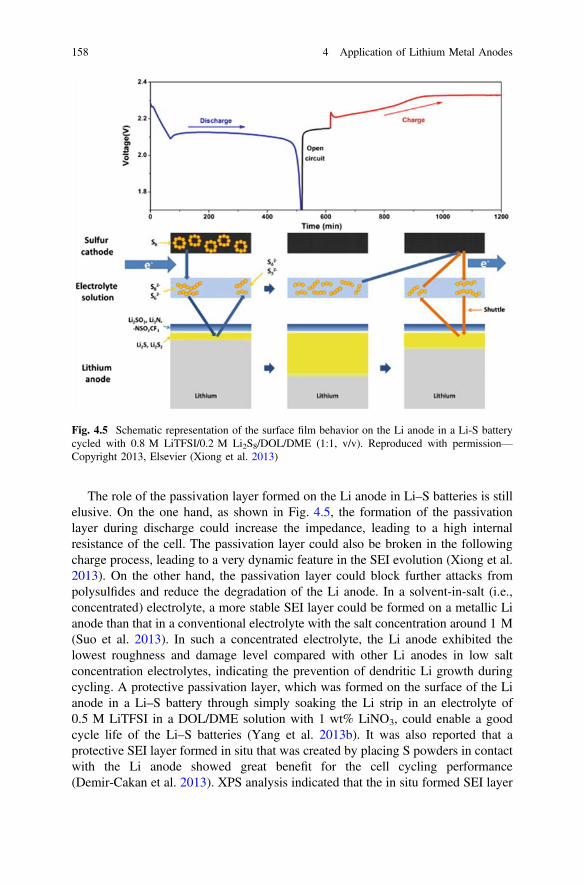
The role of the passivation layer formed on the Li anode in Li–S batteries is stillelusive. On the one hand, as shown in Fig. 4.5, the formation of the passivationlayer during discharge could increase the impedance, leading to a high internalresistance of the cell. The passivation layer could also be broken in the followingcharge process, leading to a very dynamic feature in the SEI evolution (Xiong et al.2013). On the other hand, the passivation layer could block further attacks frompolysulfides and reduce the degradation of the Li anode. In a solvent-in-salt (i.e.,concentrated) electrolyte, a more stable SEI layer could be formed on a metallic Lianode than that in a conventional electrolyte with the salt concentration around 1 M(Suo et al. 2013). In such a concentrated electrolyte, the Li anode exhibited thelowest roughness and damage level compared with other Li anodes in low saltconcentration electrolytes, indicating the prevention of dendritic Li growth duringcycling. A protective passivation layer, which was formed on the surface of the Lianode in a Li–S battery through simply soaking the Li strip in an electrolyte of0.5 M LiTFSI in a DOL/DME solution with 1 wt% LiNO3, could enable a goodcycle life of the Li–S batteries (Yang et al. 2013b). It was also reported that aprotective SEI layer formed in situ that was created by placing S powders in contactwith the Li anode showed great benefit for the cell cycling performance(Demir-Cakan et al. 2013). XPS analysis indicated that the in situ formed SEI layer
Fig. 4.5 Schematic representation of the surface film behavior on the Li anode in a Li-S batterycycled with 0.8 M LiTFSI/0.2 M Li2S8/DOL/DME (1:1, v/v). Reproduced with permission—Copyright 2013, Elsevier (Xiong et al. 2013)
158 4 Application of Lithium Metal Anodes
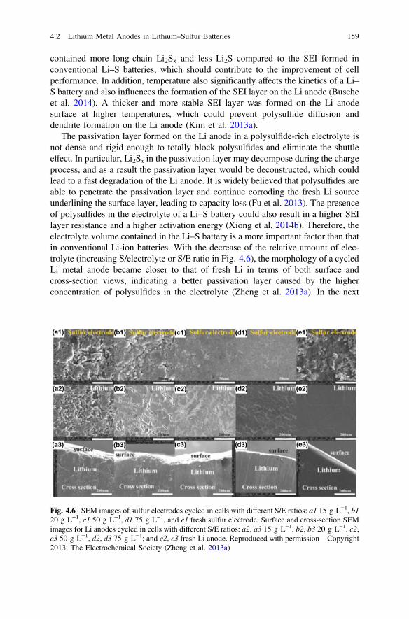
contained more long-chain Li2Sx and less Li2S compared to the SEI formed inconventional Li–S batteries, which should contribute to the improvement of cellperformance. In addition, temperature also significantly affects the kinetics of a Li–S battery and also influences the formation of the SEI layer on the Li anode (Buscheet al. 2014). A thicker and more stable SEI layer was formed on the Li anodesurface at higher temperatures, which could prevent polysulfide diffusion anddendrite formation on the Li anode (Kim et al. 2013a).
The passivation layer formed on the Li anode in a polysulfide-rich electrolyte isnot dense and rigid enough to totally block polysulfides and eliminate the shuttleeffect. In particular, Li2Sx in the passivation layer may decompose during the chargeprocess, and as a result the passivation layer would be deconstructed, which couldlead to a fast degradation of the Li anode. It is widely believed that polysulfides areable to penetrate the passivation layer and continue corroding the fresh Li sourceunderlining the surface layer, leading to capacity loss (Fu et al. 2013). The presenceof polysulfides in the electrolyte of a Li–S battery could also result in a higher SEIlayer resistance and a higher activation energy (Xiong et al. 2014b). Therefore, theelectrolyte volume contained in the Li–S battery is a more important factor than thatin conventional Li-ion batteries. With the decrease of the relative amount of elec-trolyte (increasing S/electrolyte or S/E ratio in Fig. 4.6), the morphology of a cycledLi metal anode became closer to that of fresh Li in terms of both surface andcross-section views, indicating a better passivation layer caused by the higherconcentration of polysulfides in the electrolyte (Zheng et al. 2013a). In the next
Fig. 4.6 SEM images of sulfur electrodes cycled in cells with different S/E ratios: a1 15 g L−1, b120 g L−1, c1 50 g L−1, d1 75 g L−1, and e1 fresh sulfur electrode. Surface and cross-section SEMimages for Li anodes cycled in cells with different S/E ratios: a2, a3 15 g L−1, b2, b3 20 g L−1, c2,c3 50 g L−1, d2, d3 75 g L−1; and e2, e3 fresh Li anode. Reproduced with permission—Copyright2013, The Electrochemical Society (Zheng et al. 2013a)
4.2 Lithium Metal Anodes in Lithium–Sulfur Batteries 159
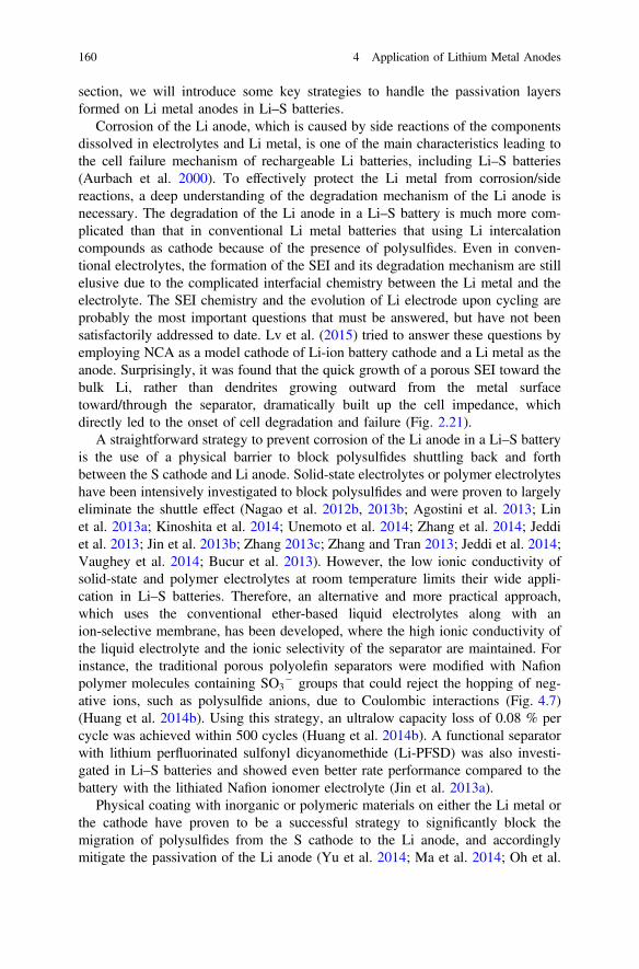
section, we will introduce some key strategies to handle the passivation layersformed on Li metal anodes in Li–S batteries.
Corrosion of the Li anode, which is caused by side reactions of the componentsdissolved in electrolytes and Li metal, is one of the main characteristics leading tothe cell failure mechanism of rechargeable Li batteries, including Li–S batteries(Aurbach et al. 2000). To effectively protect the Li metal from corrosion/sidereactions, a deep understanding of the degradation mechanism of the Li anode isnecessary. The degradation of the Li anode in a Li–S battery is much more com-plicated than that in conventional Li metal batteries that using Li intercalationcompounds as cathode because of the presence of polysulfides. Even in conven-tional electrolytes, the formation of the SEI and its degradation mechanism are stillelusive due to the complicated interfacial chemistry between the Li metal and theelectrolyte. The SEI chemistry and the evolution of Li electrode upon cycling areprobably the most important questions that must be answered, but have not beensatisfactorily addressed to date. Lv et al. (2015) tried to answer these questions byemploying NCA as a model cathode of Li-ion battery cathode and a Li metal as theanode. Surprisingly, it was found that the quick growth of a porous SEI toward thebulk Li, rather than dendrites growing outward from the metal surfacetoward/through the separator, dramatically built up the cell impedance, whichdirectly led to the onset of cell degradation and failure (Fig. 2.21).
A straightforward strategy to prevent corrosion of the Li anode in a Li–S batteryis the use of a physical barrier to block polysulfides shuttling back and forthbetween the S cathode and Li anode. Solid-state electrolytes or polymer electrolyteshave been intensively investigated to block polysulfides and were proven to largelyeliminate the shuttle effect (Nagao et al. 2012b, 2013b; Agostini et al. 2013; Linet al. 2013a; Kinoshita et al. 2014; Unemoto et al. 2014; Zhang et al. 2014; Jeddiet al. 2013; Jin et al. 2013b; Zhang 2013c; Zhang and Tran 2013; Jeddi et al. 2014;Vaughey et al. 2014; Bucur et al. 2013). However, the low ionic conductivity ofsolid-state and polymer electrolytes at room temperature limits their wide appli-cation in Li–S batteries. Therefore, an alternative and more practical approach,which uses the conventional ether-based liquid electrolytes along with anion-selective membrane, has been developed, where the high ionic conductivity ofthe liquid electrolyte and the ionic selectivity of the separator are maintained. Forinstance, the traditional porous polyolefin separators were modified with Nafionpolymer molecules containing SO3
� groups that could reject the hopping of neg-ative ions, such as polysulfide anions, due to Coulombic interactions (Fig. 4.7)(Huang et al. 2014b). Using this strategy, an ultralow capacity loss of 0.08 % percycle was achieved within 500 cycles (Huang et al. 2014b). A functional separatorwith lithium perfluorinated sulfonyl dicyanomethide (Li-PFSD) was also investi-gated in Li–S batteries and showed even better rate performance compared to thebattery with the lithiated Nafion ionomer electrolyte (Jin et al. 2013a).
Physical coating with inorganic or polymeric materials on either the Li metal orthe cathode have proven to be a successful strategy to significantly block themigration of polysulfides from the S cathode to the Li anode, and accordinglymitigate the passivation of the Li anode (Yu et al. 2014; Ma et al. 2014; Oh et al.
160 4 Application of Lithium Metal Anodes

2014; Tang et al. 2014; Liu et al. 2014b; Huang et al. 2013; Oh and Yoon 2014).Particularly, the insertion of an interlayer between the S cathode and the separatorhas been extensively explored (Jeong et al. 2013; Su and Manthiram 2012; Chungand Manthiram 2014a, b, c; Zu et al. 2013; Li et al. 2014a). Manthiram andcoworkers investigated a variety of carbon types, including an eggshell membrane(Chung and Manthiram 2014a), a microporous carbon paper (Su and Manthiram2012), a carbonized leaf (Chung and Manthiram 2014b), a carbon-coated separator(Chung and Manthiram 2014d), a carbon nanotube-coated separator (Chung andManthiram 2014c), and a treated carbon paper-based interlayer (Zu et al. 2013) as abarrier to block the polysulfide shuttle. A graphene layer coated on the separatorwas also tested in order to mitigate the polysulfide migration from the cathode to theLi anode; this enabled stable cycling up to 300 cycles (Zhou et al. 2014). Wanget al. demonstrated that the reduced graphene layer combined with a conductivecarbon black could improve the blocking effect and result in better cell performance(Wang et al. 2013b). A conductive coating on the separator of a thin layer of carbonmaterials could not only prevent the shuttle effect but also improve the utilization ofthe polysulfides accommodated in the separator (Yao et al. 2014).
Fig. 4.7 The morphologies of the routine and ion-selective membranes: a the SEM image ofroutine PP/PE/PP membrane and b ion-selective Nafion–PP/PE/PP membrane. Scale bar: 1 µm.c Cyclic and rate performance of cells. Reproduced with permission—Copyright 2014, The RoyalSociety of Chemistry (Huang et al. 2014b)
4.2 Lithium Metal Anodes in Lithium–Sulfur Batteries 161

It should be noted that the above strategies of using ion-selective membranes andcarbon interlayers in the literature reports seemed more focused on improving theutilization of the S cathodes and intercepting the migration of polysulfides, but werenot directly related to the protection of Li metal anodes. However, as discussedabove, the existence of polysulfides during discharge/charge processes of the Li–Sbattery makes the electrolyte system more complicated than that in conventionalLi-ion batteries. In fact, the attack of polysulfides on metallic Li in Li–S batteriesalways leads to quick degradation of a Li anode. Therefore, the introduction of suchion-selective membranes and/or carbon interlayers can not only improve the Sutilization in cathode, but also protect the Li anode by blocking the migration ofpolysulfides.
A different approach to protect the Li anode from attack by polysulfides has beendeveloped by Huang et al. (Figure 4.8) (Huang et al. 2014a). A hybrid anodestructure with graphite electrically connected to the Li metal in parallel wasemployed in a Li–S battery. The lithiated graphite functioned as an artificial SEIlayer on Li metal that supplies the Li+ ion on demand while minimizing directcontact between soluble polysulfides and the Li metal surface. The Li–S cellsincorporating the hybrid anodes delivered capacities >800 mAh g−1 for 400 cyclesat a high rate of 1737 mA g−1, with a CE >99 % and only 11 % capacity fade.
Fig. 4.8 Schematic of thehybrid anode design tomanipulate the surfacereactions on Li–S batteries.Reproduced with permission—Copyright 2014, MacmillanPublishers Ltd. (Huang et al.2014a)
162 4 Application of Lithium Metal Anodes

Besides insertion of a physical barrier between the S cathode and the Li anode, aconformal coating of inorganic or organic materials on the Li metal surface is alsoan effective strategy to prevent corrosion or side reactions of the Li metal fromforming a passivation layer. One example of such coating layers was formed by acrosslinking reaction of a curable monomer in the presence of liquid electrolyte anda photo-initiator (Lee et al. 2003). With the protection layer, an enhanced cellperformance was achieved in comparison with cells using a polymer electrolyte. Inanother work, conductive polymers, such as polypyrrole, have been used to form aprotective coating layer on Li powder for Li–S batteries; it can inhibit the sidereactions between the Li powder anode and dissolved polysulfides in the elec-trolyte, minimizing the overcharge and reducing the capacity fading (Oh and Yoon2014). Similarly, it has been reported that Li powders with protective coatings,compared to Li metal foil, exhibit more advantages, including dendrite suppression,leading to a safer manufacturing process and safer cell operation (Heine et al. 2014).Kim et al. (2013b) reported that a coating layer of a Li–Al alloy could mitigate thepolysulfide shuttle phenomenon in Li–S batteries. A protective film consisting of aLi–Al alloy and lithium pyrrolide film was formed on the Li electrode in an elec-trolyte containing pyrrole and AlCl3 (Wu et al. 2013). The formed protective filmwas dense and tight with high stability in the electrolyte, giving rise to a lowinterface resistance and a greatly improved cycling CE.
4.2.2 High Coulombic Efficiency and Dendrite Prevention
In Chap. 3, we have described in detail the approaches to enhance CE and preventLi dendrites in general Li metal-based batteries. In this section, our review willfocus on enhancing CE and preventing Li dendrite growth specifically related to Li–S batteries.
4.2.2.1 Effects of Liquid Electrolytes
Organic liquid electrolytes are some of the foremost electrolytes studied in literatureon Li–S batteries (Manthiram et al. 2014; Xu et al. 2014a; Chen and Shaw 2014;Scheers et al. 2014; Yin et al. 2013; Bresser et al. 2013; Song et al. 2013b; Zhang2013b; Barghamadi et al. 2013), probably due to their easy availability, vastvariation, excellent wettability on S cathodes and Li anodes, low viscosity to fill inthe micropores of the S cathode, relatively high ionic conductivity, low interfacialresistance, reasonable polysulfide solubility, good chemical stability with Li metalanodes, and a good electrochemical window. However, carbonate solvents (bothlinear and cyclic) are reactive to reduced polysulfide species (Yim et al. 2013; Gaoet al. 2011), and sulfone solvents are also incompatible with polysulfide species,according to the poor discharge and charge voltage profiles (Gao et al. 2011); thus,ether-based solvents, including glymes, are the most commonly used organic
4.2 Lithium Metal Anodes in Lithium–Sulfur Batteries 163

solvents in Li–S battery studies because of their stability with the Li metal and theircompatibility with elemental S cathodes. The Li salts commonly used in Li–Sbatteries include LiTFSI and LiSO3CF3 (or LiTf) (Zhang 2013b; Scheers et al.2014).
Song et al. (2013a) studied the effect of FEC as a co-solvent in electrolytes onthe electrochemical performance of the Li metal anode in Li–S batteries. The Li||Lisymmetric cells with the ether-based electrolytes, 1 M LiPF6 in tetra(ethyleneglycol) dimethyl ether (Tetraglyme, G4) with and without FEC, showed quitedifferent performances. The Li||Li cell with the control electrolyte without FECexploded after 4 h charging, while the symmetric cell with FEC-containingG4-based electrolyte lasted for 70 h without shorting. When the ether-based elec-trolyte was changed to a carbonate-based electrolyte, i.e., 1 M LiPF6 in EC/EMC(3:7 v/v), the Li||Li cells with the control electrolyte without FEC or with 5 % FECshowed unstable potential behavior within 5 to 6 Li stripping/deposition cycles andfailed at the 7–8 cycles. With an increase in FEC content in the carbonate solventmixture (EC/EMC/FEC), 60 % FEC could lead to at least 80 stable cycles, or1600 h of repeated stable Li stripping/deposition processes, while the controlelectrolyte showed failure at the 10th cycle. At the same time, the 60 % FEC cellshowed extremely low polarization voltage (*5 mV) after 5 Listripping/deposition cycles, and the cell impedance for the 60 % FEC cell was onlyabout one-third of that for the control cell. This FEC-derived, SEI-protected Lianode gave stable cycling performance in a Li–S battery with a LiTFSI-TEGDMEelectrolyte, but it showed decaying cycling stability in the Li–S battery with aLiPF6-TEGDME electrolyte because LiPF6 is not stable with the produced poly-sulfide species (Zhang 2013b). When the Li electrode was pretreated in a 60 % FECelectrolyte, the preformed LiF-based SEI film could slow the migration of solublepolysulfide species to the Li surface so the surface protective layer was smooth,with no physical fractures and very little S detected. On the contrary, the Li elec-trode pretreated in a G4-based electrolyte showed significant overcharging duringthe pre-cycle process in a Li–S battery, indicating the shuttle phenomenon of thesoluble polysulfides, which is due to the good compatibility of G4 and long-chainpolysulfides (Barchasz et al. 2012).
4.2.2.2 Effects of Lithium Salts
Typically, the salt concentration of an electrolyte is less than 1.2 M due to theconsiderations of ionic conductivity, viscosity, solubility, and cost. Suo et al. (2013)reported a new class of “solvent-in-salt” electrolytes of LiTFSI/DOL-DME withhigh salt concentrations up to 7 M. Although the ionic conductivity decreasedgreatly (from about 15 mS cm−1 for 1 M to 0.8 mS cm−1 for 7 M) and the vis-cosity increased significantly (from about 1 cP for 1 M to 72 cP for 7 M) with theincrease in salt concentration, the Li+ transference number increased sharply fromabout 0.46 for 1–4 M salt concentrations to about 0.73 for 5–7 M. In addition,when this ultrahigh salt concentration (7 M) electrolyte was used in Li–S batteries,
164 4 Application of Lithium Metal Anodes

it showed very little dissolution of polysulfide species, stable capacity (from aninitial 1041 mAh g−1 to 770 mAh g−1 at the 100th cycle), high capacity retention(74 % for 100 cycles), high CE (from 93.7 % for the first cycle to nearly 100 %after the second cycle), good rate capacity (1229, 988, 864, 744, and 551 mAh g−1-S at current rates of 0.2 C, 0.5 C, 1 C, 2 C, and 3 C, respectively), and goodlow-temperature performance (about 600, 550, and 350 mAh g−1 at −10, −15, and−20 °C, respectively, at 0.1 C rate). However, the lower salt concentration elec-trolytes resulted in rapid capacity fade, poor capacity retention, and a large variationof CE. More importantly, the concentrated electrolyte provided a good protection ofthe Li metal anode, showing the lowest roughness and damage levels comparedwith the Li anodes in low salt concentrations (Fig. 4.9). This demonstrated that highsalt concentration electrolytes could significantly diminish the side reactionsbetween the Li metal and the polysulfide species, effectively reduce corrosion of theLi anode, and suppress Li dendrite formation. The reasons include the inhibition ofpolysulfide dissolution and fewer free solvent molecules in the concentrated elec-trolytes. It should be noted that low conductivity and high viscosity of concentratedelectrolytes may cause significant increase of impedance of Li–S batteries.Recently, a concentrated electrolyte of 5 M LiFSI was also reported to form
Fig. 4.9 SEM images of Li anodes and Li deposition/stripping profiles: a fresh Li metal, b Lianode after 278 cycles in 2 M LiTFSI/DOL-DME, c Li anode after 183 cycles in 4 M LiTFSIelectrolyte, d Li anode after 280 cycles in 7 M LiTFSI electrolyte. The white scale bar represents60 lm. e, f, g are for electrolytes with 2 M, 4 M, and 7 M salt concentration, respectively.Reproduced with permission—Copyright 2013, MacMillan Publishers Ltd. (Suo et al. 2013)
4.2 Lithium Metal Anodes in Lithium–Sulfur Batteries 165
protective layers on both cathode and anode sides (Kim et al. 2014). Compared tothe LiTFSI-based electrolyte, the LiFSI-based electrolyte offered lower solubility ofpolysulfides, resulting in better performance in Li–S batteries.
Miao et al. (2014) used an electrolyte with dual or binary Li salts, LiFSI, andLiTFSI, dissolved in a mixed ether solvent to address the Li dendrite formation andthe low Li CE. When Li was deposited on and stripped from a SS substrate, theefficiency of the stripped charge over the deposited charge reached 91.6 % at thefirst cycle for the dual-salt electrolyte of 0.5 M LiFSI-0.5 M LiTFSI in DOL-DME(2:1 v/v) and became stable at around 99 % after several cycles, which is muchhigher than those in the conventional LiPF6/EC-DMC electrolyte for Li-ion bat-teries and the LiTFSI/DOL-DME electrolyte for Li–S batteries (Fig. 4.10a). TheLiFSI-LiTFSI dual-salt electrolyte also resulted in excellent long-term Lideposition/stripping performance for the tested 3075 h, and the overvoltages duringthe deposition/stripping processes were low (7–15 mV) and stable after more than300 h cycling (Fig. 4.10d). On the contrary, the two control electrolytes showed amuch shorter lifetime of repeated deposition/stripping cycles and the LiPF6/
Fig. 4.10 Li deposition/stripping performances in Li|electrolyte|SS cells: a CE versus cyclenumber for three different electrolytes; b, c, d galvanostatic voltage–time curves in LiPF6/EC-DMC, LiTFSI/DOL-DME and LiFSI-LiTFSI/DOL-DME, respectively. Each deposition wasconducted at 0.25 mA cm−2 for 2.5 h, and the stripping was performed at the same current densitywith a cutoff voltage of 1.2 V. Reproduced with permission—Copyright 2014, Elsevier (Miaoet al. 2014)
166 4 Application of Lithium Metal Anodes
EC-DMC electrolyte even had a higher overvoltage, up to about 44 mV(Fig. 4.10b, c, respectively).
4.2.2.3 Effect of Additives
Following successful reports by Mikhaylik (2008) and by Aurbach et al. (2009),LiNO3 has been widely used as a salt additive in electrolytes for Li–S batteries toeffectively protect the Li metal anode (Liang et al. 2011b; Zhang 2012a, b, 2013b;Xiong et al. 2011; Scheers et al. 2014; Manthiram et al. 2014). Liang et al. (2011b)reported that the addition of 0.4 M LiNO3 in a 0.5 M LiCF3SO3/DOL-4G (1:1 v/v)electrolyte could lead to quite a smooth and dense Li surface after 20 cycles.A passive film was found coated on the Li anode surface. Xiong et al. (2012)investigated the components and morphologies of the surface films on the Li anodeby using LiNO3 as the sole Li salt in an ether-based electrolyte for Li–S batteries.The strong oxidation of LiNO3 led to its reactions with electrolyte components andthe Li metal anode, resulting in a homogeneous surface film containing bothinorganic species (such as LiNxOy from the direct reduction of LiNO3 by Li metaland Li2SOy from the oxidation of sulfur) and organic species (such as ROLi andROCO2Li), as Aurbach et al. (2009) indicated. When Li metal was immersed in theLiNO3-containing electrolyte, the Li metal surface became more smooth andcompact with a longer immersion time (as shown in Fig. 4.11). This homogeneousand compact surface film would enhance the stability of the Li metal anode andimprove the cycle life of Li–S batteries.
Besides LiNO3, several other salts and ILs have been reported as electrolyteadditives in Li–S batteries to suppress Li dendrite formation. Xiong et al. (2011)studied the effect of LiBOB as an electrolyte additive for electrochemical propertiesand Li surface morphologies in Li–S batteries. With the increase of LiBOB contentin 1 M LiTFSI/DOL-DME (1:1 v/v) from 0 to 10 wt%, the a.c. impedance of the Lianode increased and the discharge capacity of the Li–S battery showed a maximumvalue at 4 % LiBOB content. However, the cycling stability of Li–S batteries withvarious LiBOB contents was poor, and nearly no difference could be observed fordifferent LiBOB contents. The authors speculated that the main reasons wereattributed to the formation of irreversible Li2S, structural invalidation of the cathodematrix, and the parasitic reactions between polysulfides and the Li metal. Theimpact of LiBOB on the cycling performance was small. However, the addition ofLiBOB in the electrolyte did form smoother and denser surface morphology on theLi anode, and the roughness of this surface morphology reduced as LiBOB contentincreased. In contrast, without LiBOB, the Li anode surface showed looselycompacted needle-like dendrites after 50 cycles, causing serious safety concerns.Therefore, the addition of LiBOB as an additive or co-salt could prevent thereactions between the electrolyte and the Li metal.
Wu et al. (2014) investigated the protection of Li anode and improvement ofcycling performance for Li–S batteries by using LiDFOB as an additive in theelectrolyte of 1 M LiTFSI/DOL-DME. In the control electrolyte without LiDFOB,
4.2 Lithium Metal Anodes in Lithium–Sulfur Batteries 167
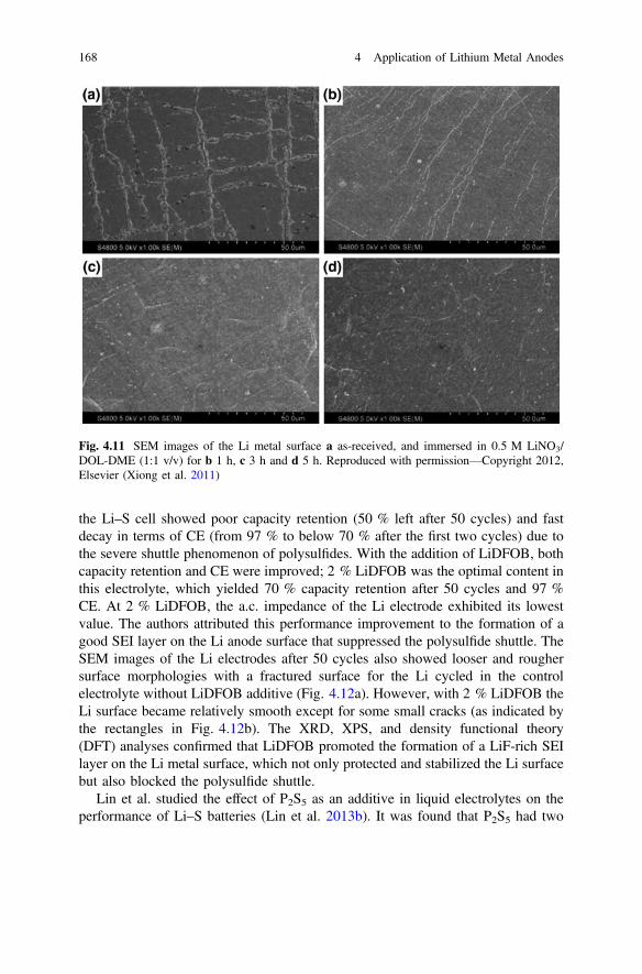
the Li–S cell showed poor capacity retention (50 % left after 50 cycles) and fastdecay in terms of CE (from 97 % to below 70 % after the first two cycles) due tothe severe shuttle phenomenon of polysulfides. With the addition of LiDFOB, bothcapacity retention and CE were improved; 2 % LiDFOB was the optimal content inthis electrolyte, which yielded 70 % capacity retention after 50 cycles and 97 %CE. At 2 % LiDFOB, the a.c. impedance of the Li electrode exhibited its lowestvalue. The authors attributed this performance improvement to the formation of agood SEI layer on the Li anode surface that suppressed the polysulfide shuttle. TheSEM images of the Li electrodes after 50 cycles also showed looser and roughersurface morphologies with a fractured surface for the Li cycled in the controlelectrolyte without LiDFOB additive (Fig. 4.12a). However, with 2 % LiDFOB theLi surface became relatively smooth except for some small cracks (as indicated bythe rectangles in Fig. 4.12b). The XRD, XPS, and density functional theory(DFT) analyses confirmed that LiDFOB promoted the formation of a LiF-rich SEIlayer on the Li metal surface, which not only protected and stabilized the Li surfacebut also blocked the polysulfide shuttle.
Lin et al. studied the effect of P2S5 as an additive in liquid electrolytes on theperformance of Li–S batteries (Lin et al. 2013b). It was found that P2S5 had two
Fig. 4.11 SEM images of the Li metal surface a as-received, and immersed in 0.5 M LiNO3/DOL-DME (1:1 v/v) for b 1 h, c 3 h and d 5 h. Reproduced with permission—Copyright 2012,Elsevier (Xiong et al. 2011)
168 4 Application of Lithium Metal Anodes

functionalities: one was to promote the dissolution of Li2S in order to alleviate thecapacity loss by the precipitation of Li2S, and the other was to passivate the Lianode surface so as to eliminate the polysulfide shuttle. The passivation layer wasabout 3–5 lm thick with granular particles less than 100 nm large, which weremainly Li3PS4. Due to the superionic conductivity of Li3PS4 for Li
+, the thick buthighly ionically conductive SEI layer could enhance the Li+ transportation to andfrom the Li anode but greatly reduce the polysulfide diffusion and reaction with theLi anode. As a result, the Li metal anode was protected; the CE and cyclingperformance were improved.
Recently, Zu and Manthiram (2014) reported using copper acetate [Cu(OOCCH3)2 or CuAc2] as a surface stabilizer for the Li metal anode in Li–Sbatteries, with an electrolyte of CF3SO3Li in DOL/DME with LiNO3. The controlcell (without CuAc2) had a sudden capacity decay to 0 mAh g−1 at a cycle numberclose to 100 cycles, likely due to the Li anode degradation. However, with theaddition of 0.03 M CuAc2 in the electrolyte, the cell showed a capacity retention of75 % at the 300th cycle, and a CE of 100 % for most of the cycles; the cell internalresistance was also lower than that of the control cell. The Li anode surfacesshowed different morphologies after cycling in the two electrolytes with andwithout CuAc2. After the first discharge/charge cycle, the Li anode from the controlelectrolyte contained bulk Li2S/Li2S2 precipitates on the surface and exhibitednonuniformly deposited mossy Li (Fig. 4.13a). The Li anode from the CuAc2-containing electrolyte had a smooth surface and was covered by an S- andCu-containing passivation film (Fig. 4.13b). After 100 cycles, the Li anode from thecontrol electrolyte showed dendritic morphology and a large amount ofS-containing species (Fig. 4.13c), while the Li anode from the CuAc2-containingelectrolyte was uniform (Fig. 4.13d). As shown in the cross-sectional energy dis-persive spectroscopy (EDS) line scans (Fig. 4.13e, f), S was only detected in the top20 lm of the surface film on the Li anode cycled in the CuAc2-based electrolyte,indicating the effective blocking of polysulfide penetration, thus preventing the
Fig. 4.12 SEM images of Li electrodes after 50 cycles with (a) no LiDFOB and (b) 2 % LiDFOB.Reproduced with permission—Copyright 2014, American Chemical Society (Wu et al. 2014)
4.2 Lithium Metal Anodes in Lithium–Sulfur Batteries 169
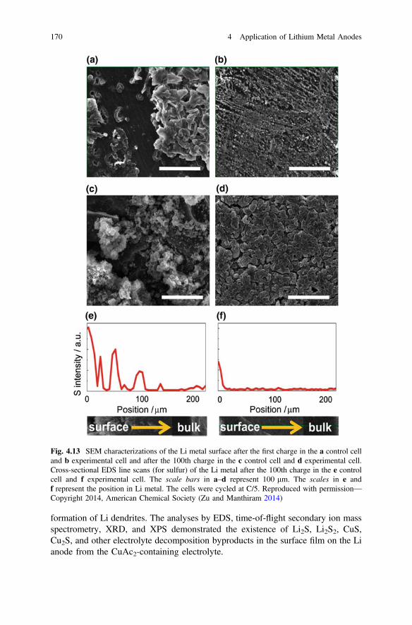
formation of Li dendrites. The analyses by EDS, time-of-flight secondary ion massspectrometry, XRD, and XPS demonstrated the existence of Li2S, Li2S2, CuS,Cu2S, and other electrolyte decomposition byproducts in the surface film on the Lianode from the CuAc2-containing electrolyte.
Fig. 4.13 SEM characterizations of the Li metal surface after the first charge in the a control celland b experimental cell and after the 100th charge in the c control cell and d experimental cell.Cross-sectional EDS line scans (for sulfur) of the Li metal after the 100th charge in the e controlcell and f experimental cell. The scale bars in a–d represent 100 lm. The scales in e andf represent the position in Li metal. The cells were cycled at C/5. Reproduced with permission—Copyright 2014, American Chemical Society (Zu and Manthiram 2014)
170 4 Application of Lithium Metal Anodes

Zheng et al. also studied the properties and morphologies of the SEI layersformed on the Li metal surface in Li–S batteries by adding the IL1-butyl-1-methylpyrrolidinium bis(trifluoromethanesulfonyl)-imide (Pyr14TFSI) inthe electrolyte of 1 M LiTFSI/DME-DOL. It was found that the electrolyte with75 % Pyr14TFSI in the DME-DOL-Pyr14TFSI mixture gave the Li–S batteries thebest cycling stability, highest CE, and highest capacity after 30 cycles among the ILcontents from 0 to 100 % in the solvent mixture. The IL-enhanced passivation filmon the Li anode surface exhibited very different morphology and chemical com-position, effectively protecting the Li metal from continuous attack by solublepolysulfides (see Fig. 4.14) (Zheng et al. 2013b).
4.2.2.4 Effect of Solid Electrolytes
Possible solutions to completely block Li dendrite penetration through the elec-trolytes include solid-state inorganic electrolytes, which normally are glassy orceramic, and solid polymer electrolytes. In a recent review paper on Li metal anodesfor rechargeable batteries, we have summarized previous achievements in usingpolymer electrolytes and inorganic solid-state Li-ion conductors to block the pen-etration of Li dendrites (Xu et al. 2014b). So far, there are several papers reportingthe use of such solid-state polymer electrolytes (Marmorstein et al. 2000; Shin et al.2002; Yu et al. 2004; Hassoun and Scrosati 2010; Liang et al. 2011a) and inorganicelectrolytes (Hayashi et al. 2003, 2008; Nagao et al. 2011, 2012a, 2013; Lin et al.2013a; Hakari et al. 2014) in Li–S related batteries. However, there are no directreports about using solid-state polymer electrolytes and inorganic electrolytes tosuppress Li dendrites in Li–S batteries. We expect that the use of solid-state
Fig. 4.14 SEM images of the Li metal surface and cross-section of fresh Li metal (a1 and a2) andLi metal cycled in the baseline electrolyte (b1 and b2), electrolyte containing 50 % IL (c1 and c2),and electrolyte containing 75 % IL (d1 and d2) for 100 cycles at 0.2 C. Reproduced withpermission—Copyright 2013, The Royal Society of Chemistry (Zheng et al. 2013b)
4.2 Lithium Metal Anodes in Lithium–Sulfur Batteries 171

inorganic electrolytes can prevent Li dendrite growth and penetration in Li–Sbatteries on the basis of previous reports and knowledge. However, one precautionfor using such SSEs is the high interfacial resistance between the solid electrolytewith the S cathode and the Li metal anode. The ability to reduce such interfacialresistances is a big challenge in all solid-state Li–S batteries.
4.2.2.5 Effect of Ex Situ Formed Coating Layers
The protection layers on the Li anode surface are normally formed in situ in liquidelectrolytes as discussed above. An alternative approach to protect the Li anode is topre-form a thin barrier on the Li surface. Kim et al. (2013b) reported the formationof a thin Li–Al alloy layer on the Li surface to protect the Li anode. They laminateda very thin Al foil (0.8 lm) on the Li surface using pressure, and then cured at threedifferent temperatures (25, 60 and 90 °C) for one day. The Li metal with the formedLi–Al thin layer was analyzed and tested in Li–S batteries with a high-concentrationelectrolyte of 3 M LiTFSI/DOL-DME. The curing temperature affected the elec-trochemical performance of the Li anode. The Li–Al alloy coating layer cured at90 °C led to the lowest charge transfer resistance, the lowest polarization voltage,and the best rate capability, which were ascribed to good protection of the Li anode.However, the long-term cycling stability results showed that after 300 cycles, thedischarge capacity of the Li–S cell with the Li–Al alloy layer cured at 90 °C wasnearly the same as that of a pure Li anode, indicating continuous decay of this alloyprotection layer. This is likely related to the high volume change of the Li–Al alloyduring de-alloying/re-alloying processes that take place during the charge/dischargecycles.
4.3 Lithium Metal Anodes in Lithium-Air Batteries
Li-air batteries have much higher specific energies than most currently availableprimary and rechargeable batteries (Hamlen and Atwater 2001; Blurton andSammells 1979; Arai and Hayashi 2009; Haas and Van Wesemael 2009; Viscoet al. 2009; Smedley and Zhang 2009; Zhang 2009; Egashira 2009; Joerissen 2009).A significant amount of work was conducted on Li-air batteries in the 1960s andearly 1970s (Gregory 1972; Blurton and Oswin 1972; Oswin 1967); however,efforts in this field decreased considerably in the 1980s because of problemsassociated with the stability of Li metal anodes and air electrodes, thermal man-agement, and the reversibility of the system. Recent advances in electrode materialsand electrolytes, as well as new designs for Li-air batteries, have renewed intensiveefforts, especially in the development of Li-air batteries (Abraham and Jiang 1996a,b; Dobley et al. 2006c). In contrast to most other batteries that must carry bothanode and cathode inside a storage system, Li-air batteries are unique in that theactive cathode material (oxygen) is not stored in the battery. Instead, oxygen can be
172 4 Application of Lithium Metal Anodes
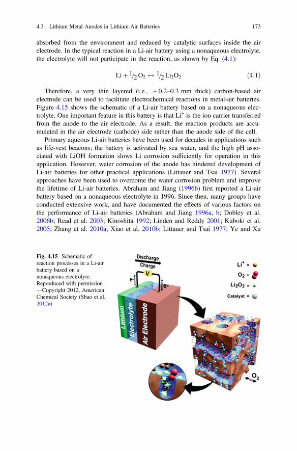
absorbed from the environment and reduced by catalytic surfaces inside the airelectrode. In the typical reaction in a Li-air battery using a nonaqueous electrolyte,the electrolyte will not participate in the reaction, as shown by Eq. (4.1):
Liþ 1=2O2 $ 1=2 Li2O2 ð4:1Þ
Therefore, a very thin layered (i.e., *0.2–0.3 mm thick) carbon-based airelectrode can be used to facilitate electrochemical reactions in metal-air batteries.Figure 4.15 shows the schematic of a Li-air battery based on a nonaqueous elec-trolyte. One important feature in this battery is that Li+ is the ion carrier transferredfrom the anode to the air electrode. As a result, the reaction products are accu-mulated in the air electrode (cathode) side rather than the anode side of the cell.
Primary aqueous Li-air batteries have been used for decades in applications suchas life-vest beacons; the battery is activated by sea water, and the high pH asso-ciated with LiOH formation slows Li corrosion sufficiently for operation in thisapplication. However, water corrosion of the anode has hindered development ofLi-air batteries for other practical applications (Littauer and Tsai 1977). Severalapproaches have been used to overcome the water corrosion problem and improvethe lifetime of Li-air batteries. Abraham and Jiang (1996b) first reported a Li-airbattery based on a nonaqueous electrolyte in 1996. Since then, many groups haveconducted extensive work, and have documented the effects of various factors onthe performance of Li-air batteries (Abraham and Jiang 1996a, b; Dobley et al.2006b; Read et al. 2003; Kinoshita 1992; Linden and Reddy 2001; Kuboki et al.2005; Zhang et al. 2010a; Xiao et al. 2010b; Littauer and Tsai 1977; Ye and Xu
Fig. 4.15 Schematic ofreaction processes in a Li-airbattery based on anonaqueous electrolyte.Reproduced with permission—Copyright 2012, AmericanChemical Society (Shao et al.2012a)
4.3 Lithium Metal Anodes in Lithium-Air Batteries 173
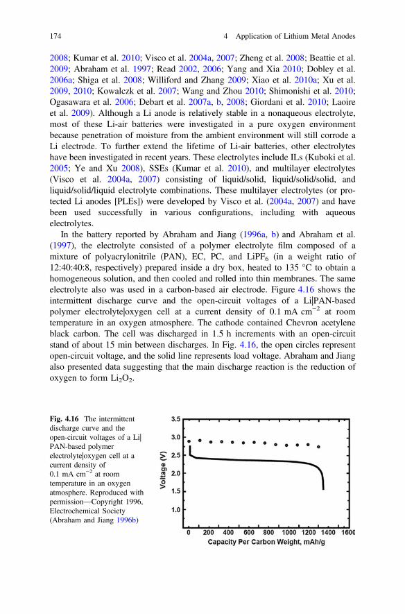
2008; Kumar et al. 2010; Visco et al. 2004a, 2007; Zheng et al. 2008; Beattie et al.2009; Abraham et al. 1997; Read 2002, 2006; Yang and Xia 2010; Dobley et al.2006a; Shiga et al. 2008; Williford and Zhang 2009; Xiao et al. 2010a; Xu et al.2009, 2010; Kowalczk et al. 2007; Wang and Zhou 2010; Shimonishi et al. 2010;Ogasawara et al. 2006; Debart et al. 2007a, b, 2008; Giordani et al. 2010; Laoireet al. 2009). Although a Li anode is relatively stable in a nonaqueous electrolyte,most of these Li-air batteries were investigated in a pure oxygen environmentbecause penetration of moisture from the ambient environment will still corrode aLi electrode. To further extend the lifetime of Li-air batteries, other electrolyteshave been investigated in recent years. These electrolytes include ILs (Kuboki et al.2005; Ye and Xu 2008), SSEs (Kumar et al. 2010), and multilayer electrolytes(Visco et al. 2004a, 2007) consisting of liquid/solid, liquid/solid/solid, andliquid/solid/liquid electrolyte combinations. These multilayer electrolytes (or pro-tected Li anodes [PLEs]) were developed by Visco et al. (2004a, 2007) and havebeen used successfully in various configurations, including with aqueouselectrolytes.
In the battery reported by Abraham and Jiang (1996a, b) and Abraham et al.(1997), the electrolyte consisted of a polymer electrolyte film composed of amixture of polyacrylonitrile (PAN), EC, PC, and LiPF6 (in a weight ratio of12:40:40:8, respectively) prepared inside a dry box, heated to 135 °C to obtain ahomogeneous solution, and then cooled and rolled into thin membranes. The sameelectrolyte also was used in a carbon-based air electrode. Figure 4.16 shows theintermittent discharge curve and the open-circuit voltages of a Li|PAN-basedpolymer electrolyte|oxygen cell at a current density of 0.1 mA cm−2 at roomtemperature in an oxygen atmosphere. The cathode contained Chevron acetyleneblack carbon. The cell was discharged in 1.5 h increments with an open-circuitstand of about 15 min between discharges. In Fig. 4.16, the open circles representopen-circuit voltage, and the solid line represents load voltage. Abraham and Jiangalso presented data suggesting that the main discharge reaction is the reduction ofoxygen to form Li2O2.
Fig. 4.16 The intermittentdischarge curve and theopen-circuit voltages of a Li|PAN-based polymerelectrolyte|oxygen cell at acurrent density of0.1 mA cm−2 at roomtemperature in an oxygenatmosphere. Reproduced withpermission—Copyright 1996,Electrochemical Society(Abraham and Jiang 1996b)
174 4 Application of Lithium Metal Anodes
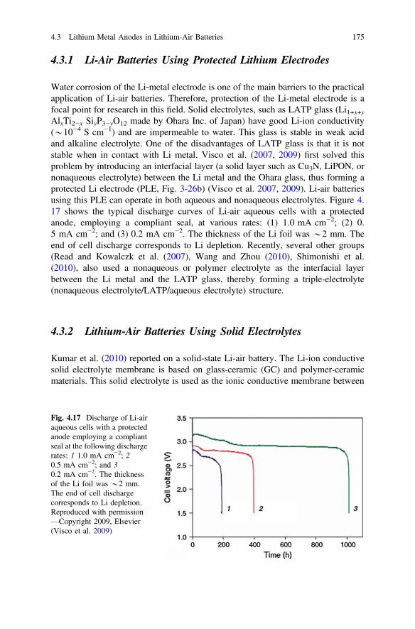
4.3.1 Li-Air Batteries Using Protected Lithium Electrodes
Water corrosion of the Li-metal electrode is one of the main barriers to the practicalapplication of Li-air batteries. Therefore, protection of the Li-metal electrode is afocal point for research in this field. Solid electrolytes, such as LATP glass (Li1+x+yAlxTi2−x SiyP3−yO12 made by Ohara Inc. of Japan) have good Li-ion conductivity(*10−4 S cm−1) and are impermeable to water. This glass is stable in weak acidand alkaline electrolyte. One of the disadvantages of LATP glass is that it is notstable when in contact with Li metal. Visco et al. (2007, 2009) first solved thisproblem by introducing an interfacial layer (a solid layer such as Cu3N, LiPON, ornonaqueous electrolyte) between the Li metal and the Ohara glass, thus forming aprotected Li electrode (PLE, Fig. 3-26b) (Visco et al. 2007, 2009). Li-air batteriesusing this PLE can operate in both aqueous and nonaqueous electrolytes. Figure 4.17 shows the typical discharge curves of Li-air aqueous cells with a protectedanode, employing a compliant seal, at various rates: (1) 1.0 mA cm−2; (2) 0.5 mA cm−2; and (3) 0.2 mA cm−2. The thickness of the Li foil was *2 mm. Theend of cell discharge corresponds to Li depletion. Recently, several other groups(Read and Kowalczk et al. (2007), Wang and Zhou (2010), Shimonishi et al.(2010), also used a nonaqueous or polymer electrolyte as the interfacial layerbetween the Li metal and the LATP glass, thereby forming a triple-electrolyte(nonaqueous electrolyte/LATP/aqueous electrolyte) structure.
4.3.2 Lithium-Air Batteries Using Solid Electrolytes
Kumar et al. (2010) reported on a solid-state Li-air battery. The Li-ion conductivesolid electrolyte membrane is based on glass-ceramic (GC) and polymer-ceramicmaterials. This solid electrolyte is used as the ionic conductive membrane between
Fig. 4.17 Discharge of Li-airaqueous cells with a protectedanode employing a compliantseal at the following dischargerates: 1 1.0 mA cm−2; 20.5 mA cm−2; and 30.2 mA cm−2. The thicknessof the Li foil was *2 mm.The end of cell dischargecorresponds to Li depletion.Reproduced with permission—Copyright 2009, Elsevier(Visco et al. 2009)
4.3 Lithium Metal Anodes in Lithium-Air Batteries 175
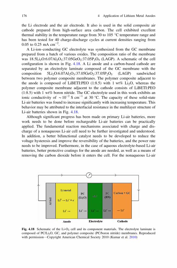
the Li electrode and the air electrode. It also is used in the solid composite aircathode prepared from high-surface area carbon. The cell exhibited excellentthermal stability in the temperature range from 30 to 105 °C temperature range andhas been tested for 40 charge-discharge cycles at current densities ranging from0.05 to 0.25 mA cm−2.
A Li-ion–conducting GC electrolyte was synthesized from the GC membraneprepared from a batch of various oxides. The composition ratio of the membranewas 18.5Li2O:6.07Al2O3:37.05GeO2:37.05P2O5 (LAGP). A schematic of the cellconfiguration is shown in Fig. 4.18. A Li anode and a carbon-based cathode areseparated by an electrolyte laminate composed of the GC membrane with thecomposition 5Li2O:6.07Al2O3:37.05GeO2:37.05P2O5 (LAGP) sandwichedbetween two polymer composite membranes. The polymer composite adjacent tothe anode is composed of LiBETI:PEO (1:8.5) with 1 wt% Li2O, whereas thepolymer composite membrane adjacent to the cathode consists of LiBETI:PEO(1:8.5) with 1 wt% boron nitride. The GC electrolyte used in this work exhibits anionic conductivity of *10−2 S cm−1 at 30 °C. The capacity of these solid-stateLi-air batteries was found to increase significantly with increasing temperature. Thisbehavior may be attributed to the interfacial resistance in the multilayer structure ofLi-air batteries shown in Fig. 4.18.
Although significant progress has been made on primary Li-air batteries, morework needs to be done before rechargeable Li-air batteries can be practicallyapplied. The fundamental reaction mechanisms associated with charge and dis-charge of a nonaqueous Li-air cell need to be further investigated and understood.In addition, a better bifunctional catalyst needs to be developed to reduce thevoltage hysteresis and improve the reversibility of the batteries, and the power rateneeds to be improved. Furthermore, in the case of aqueous electrolyte-based Li-airbatteries, better protective coatings for the anode are needed, as well as a means ofremoving the carbon dioxide before it enters the cell. For the nonaqueous Li-air
Fig. 4.18 Schematic of the Li-O2 cell and its component materials. The electrolyte laminate iscomposed of PC/Li2O, GC, and polymer composite (PC/boron nitride) membranes. Reproducedwith permission—Copyright American Chemical Society 2010 (Kumar et al. 2010)
176 4 Application of Lithium Metal Anodes

design, one of the challenges is to avoid the ingress of water, which may react withLi metal and reduce the lifetime of the batteries.
4.4 Anode-Free Lithium Batteries
A commercial Li-ion battery consists of multiple stacks of anode currentcollector/anode|separator|cathode/cathode current collector soaked with liquidelectrolyte (such as 1 M LiPF6 in carbonate co-solvents). For example, a commonLi-ion battery used in commercial electronics has a structure of Cu/graphite|sepa-rator|LiCoO2/Al or Cu/graphite|separator|LiFePO4/Al (Jiang et al. 2014; Sun et al.2012). The operating principle of these Li-ion batteries could be described asfollows. During the charging process, the Li ions are extracted out of cathodematerials, diffuse through electrolyte soaked in separator, and then intercalate intothe anode materials (i.e., graphite). The process is reversed during the dischargingprocess. In this system, each component counts in the total weight and cost of thewhole system, although the inactive components including separator, Cu/Al currentcollectors, and the packaging materials do not contribute to the usable energy.
Ideally, if the Li ions extracted from a cathode can be reversibly deposited ontoand stripped from a Cu current collector, then it is possible to assemble arechargeable Li battery with a structure of Cu|separator|cathode/Al. This batterycontains no active anode material as prepared, and can be called an “anode-free Libattery” (AFLB). A schematic illustration of an AFLB concept is presented inFig. 4.19, where the state-of-the-art Li-ion battery configuration (Fig. 4.19a) is alsoshown as a reference. In an anode-free battery configuration, all active Li+ ions arestored inside the cathode electrode (Fig. 4.19b). During the initial charging process,Li ions are extracted from the cathode and diffuse toward the anode current col-lector, where they are electrodeposited as metallic Li. During the subsequentcharging process, Li will be stripped from the anode and intercalated back into the
Fig. 4.19 Schematic illustration of a state-of-the-art Li-ion battery (i.e., Cu/graphite||LiFePO4/Al)and b an anode-free battery (i.e., Cu||LiFePO4/Al)
4.3 Lithium Metal Anodes in Lithium-Air Batteries 177

cathode (Ding et al. 2013; Zheng et al. 2014; Lu et al. 2014). Traditionally, thisbattery structure was considered to be impossible, let alone able to survive for manycycles. In addition to the long-term concern regarding dendritic Li growth thatwould penetrate through the separator and short the cell (Aurbach et al. 2002;López et al. 2009; Miao et al. 2014), another direct concern with “anode-free”battery structure is that Li cycling CE is very low, usually less than 80 % in mostnonaqueous electrolytes. As a consequence, the in situ plated Li supplied from thecathode electrodes will be readily consumed after fewer than ten cycles. In thisregard, the key point to realize the anode-free concept is the development of afunctional electrolyte in which Li deposition is dendrite free along with high CEand good cycling stability.
The anode-free battery configuration exhibits several advantages. First, theabsence of active anode electrode in the as-assembled batteries will reduce theweight and space reserved for the anode. In typical Li-ion batteries, the thickness ofthe graphite anode is similar to that of the cathode (typically a Li intercalationcompound). If the graphite anode can be eliminated in anode-free batteries, thethickness of the active materials (cathode/anode) can be reduced to half of that ofLi-ion batteries. Even considering other inactive materials, the energy density(Wh L−1) of the battery can be increased by more than 50 %. Second, it will saveenergy and cost in anode electrode preparation, including electrode slurry making,slurry coating, and drying. Last but not least, it will operate as a Li metal batteryafter the initial charge process, providing higher operating voltage and energydensity than Li-ion batteries using graphite as the anode.
Although the AFLB has many advantages, tremendous barriers need to beovercome before its practical application. The most critical barrier in these batteriesis the very high CE required for an AFLB to have a meaningful lifetime. Table 4.1shows the cycle life of a battery with different Li cycling CEs. Here we assume thatthe cathode of the battery has no degradation and the battery fails if its capacitydrops to less than 80 % of the original values. At a CE of 99 %, the battery only hasa lifetime of 22 cycles. For a rechargeable battery to have a significant lifetime, suchas more than 100 cycles, the Li metal anode has to have a CE of at least 99.8 %. Ata CE of larger than 99.9 %, an AFLB can have a lifetime of more than a fewhundred cycles. At such a high CE, not only the Li metal anode, but all other batterycomponents have to be stable during the electrochemical cycling process. Inaddition, to evaluate such a high CE, a high precision battery tester is required to
Table 4.1 CE required to retain more than 80 % of the battery capacities
Coulombic efficiency (%) Cycles to maintain a capacity >80 % of initial value
99 22
99.7 74
99.8 112
99.9 223
99.99 2231
178 4 Application of Lithium Metal Anodes

obtain a reliable evaluation of the Li cycling CE. Further development of thistechnology may lead to practical application of these batteries in the future.
Using solid-state electrolytes such as LiPON has been regarded as a promisingsolution for anode-free batteries, owing to their good compatibility with Li(Neudecker et al. 2000; Bates et al. 1993, 1995; Lee et al. 2004). However, theintrinsically low conductivity of LiPON and their high cost has limited the appli-cation of these batteries (Wang et al. 2015a; Bates et al. 1993, 1995). Therefore,only thin-film electrodes with an areal capacity of *100 lAh cm−2 have beenreported, limiting their applications in microelectronic devices that do not requirehigh energy or power supply (Neudecker et al. 2000). A liquid organic electrolytewith high conductivity and wettability can be used for the thick electrode in Limetal cells. However, the traditional carbonate-based electrolyte system has poorcompatibility with Li metal (due to Li dendrite growth and low CE) and thereforecould not be used for anode-free cell design (Woo et al. 2014; Aurbach et al. 2002;Xu et al. 2014b).
Qian et al. (2015b) demonstrated that the highly concentrated electrolytescomposed of ether solvents and the LiFSI salt enabled high-rate cycling of a Limetal anode with high CE (up to 99.1 %) without dendrite growth; this wasascribed to the enhanced solvent coordination and improved availability of Li+ ionconcentration in the electrolyte. They also demonstrated an anode-free Li celldesign (Cu||LiFePO4) with highly concentrated electrolyte (4 M LiFSI/DME) anddelivered high initial discharge capacities close to the nominal capacity of thecathode. The battery retained *60 % of its original capacity after 50 cycles alongwith an average CE >99 % during cycling. The CE of these batteries can be furtherimproved by adopting a slow charge/fast discharge protocol resulting in anexceptionally high CE of more than 99.8 % (Qian et al. 2016). The in situ formed Li(during charging) is largely stabilized due to minimized reactions between theplated Li and concentrated electrolyte. These works and the insights obtained forthe SEI characteristics demonstrate a possible path forward for enabling Li metal asa highly reversible and safe practical battery anode.
References
Abraham KM, Jiang Z (1996a) Solid polymer electrolyte-based oxygen batteries. US 5510209Abraham KM, Jiang Z (1996b) A polymer electrolyte-based rechargeable lithium/oxygen battery.
J Electrochem Soc 143(1):1–5Abraham KM, Jiang Z, Carroll B (1997) Highly conductive PEO-like polymer electrolytes. Chem
Mater 9(9):1978–1988Agostini M, Aihara Y, Yamada T, Scrosati B, Hassoun J (2013) A lithium–sulfur battery using a
solid, glass-type P2S5–Li2S electrolyte. Solid State Ionics 244:48–51. doi:http://dx.doi.org/10.1016/j.ssi.2013.04.024
Arai H, Hayashi M (2009) Secondary batteries-metal-air systems: overview (secondary andprimary). In: Garche J, Dyer C, Moseley P, Ogumi Z, Rand D, Scrosati B (eds) Encyclopediaof electrochemical power sources, vol 5. Elsevier, Amsterdam, pp 347–355
4.4 Anode-Free Lithium Batteries 179

Aurbach D, Zinigrad E, Teller H, Dan P (2000) Factors which limit the cycle life of rechargeablelithium (metal) batteries. J Electrochem Soc 147:1274–1279
Aurbach D, Zinigrad E, Cohen Y, Teller H (2002) A short review of failure mechanisms of lithiummetal and lithiated graphite anodes in liquid electrolyte solutions. Solid State Ionics 148:405–416
Aurbach D, Pollak E, Elazari R, Salitra G, Kelley CS, Affinito J (2009) On the surface chemicalaspects of very high energy density, rechargeable Li–sulfur batteries. J Electrochem Soc 156(8):A694–A702. doi:10.1149/1.3148721
Autolib’ Bluecar carsharing service, Paris, France, by Mariordo (Mario Roberto Durán Ortiz) islicensed under CC BY-SA 3.0 and found on Wikipedia https://en.wikipedia.org/wiki/Bollor%C3%A9_Bluecar#/media/File:Paris_Autolib_06_2012_Bluecar_2907.JPG. Accessed 31 May2016
Barchasz C, Molton F, Duboc C, Leprêtre J-C, Patoux S, Alloin F (2012) Lithium/sulfur celldischarge mechanism: an original approach for intermediate species identification. Anal Chem84(9):3973–3980. doi:10.1021/ac2032244
Barchasz C, Lepretre JC, Patoux S, Alloin F (2013a) Revisiting TEGDME/DIOX binaryelectrolytes for lithium/sulfur batteries: importance of solvation ability and additives.J Electrochem Soc 160(3):A430–A436. doi:10.1149/2.022303jes
Barchasz C, Leprêtre J-C, Patoux S, Alloin F (2013b) Electrochemical properties of ether-basedelectrolytes for lithium/sulfur rechargeable batteries. Electrochim Acta 89:737–743. doi:10.1016/j.electacta.2012.11.001
Barghamadi M, Kapoor A, Wen C (2013) A review on Li-S batteries as a high efficiencyrechargeable lithium battery. J Electrochem Soc 160(8):A1256–A1263. doi:10.1149/2.096308jes
Bates JB, Dudney NJ, Gruzalski GR, Zuhr RA, Choudhury A, Luck CF, Robertson JD (1993)Fabrication and characterization of amorphous lithium electrolyte thin-films and rechargeablethin-film batteries. J Power Sources 43(1–3):103–110. doi:10.1016/0378-7753(93)80106-y
Bates JB, Dudney NJ, Lubben DC, Gruzalski GR, Kwak BS, Yu X, Zuhr RA (1995) Thin-filmrechargeable lithium batteries. J Power Sources 54(1):58–62. doi:http://dx.doi.org/10.1016/0378-7753(94)02040-A
Beattie SD, Manolescu DM, Blair SL (2009) High-capacity lithium-air cathodes. J ElectrochemSoc 156(1):A44–A47. doi:10.1149/1.3005989
Blurton KF, Oswin HG (1972) Refuelable batteries. In: Proceedings of the symposium onnon-fossil chemical fuels, preprints of papers presented at the 163rd national meeting of theAmerican Chemical Society, vol 2, Boston, Massachusetts, 10–14 April 1972, AmericanChemical Society, Division of Fuel Chemistry, Washington DC, pp 48–69
Blurton KF, Sammells AF (1979) Metal-air batteries—their status and potential—review. J PowerSources 4(4):263–279
Bresser D, Passerini S, Scrosati B (2013) Recent progress and remaining challenges insulfur-based lithium secondary batteries—a review. Chem Commun 49(90):10545–10562.doi:10.1039/C3CC46131A
Bruce PG, Freunberger SA, Hardwick LJ, Tarascon J-M (2012) Li-O2 and Li-S batteries with highenergy storage. Nat Mater 11(1):19–29
Brückner J, Thieme S, Böttger-Hiller F, Bauer I, Grossmann HT, Strubel P, Althues H, Spange S,Kaskel S (2014) Carbon-based anodes for lithium sulfur full cells with high cycle stability. AdvFunct Mater 24(9):1284–1289. doi:10.1002/adfm.201302169
Bryngelsson H, Stjerndahl M, Gustafsson T, Edström K (2007) How dynamic is the SEI? J PowerSources 174(2):970–975. doi:10.1016/j.jpowsour.2007.06.050
Bucur CB, Muldoon J, Lita A, Schlenoff JB, Ghostine RA, Dietz S, Allred G (2013) Ultrathintunable ion conducting nanomembranes for encapsulation of sulfur cathodes. Energy EnvironSci 6(11):3286–3290. doi:10.1039/C3EE42739K
Busche MR, Adelhelm P, Sommer H, Schneider H, Leitner K, Janek J (2014) Systematicalelectrochemical study on the parasitic shuttle-effect in lithium-sulfur-cells at different
180 4 Application of Lithium Metal Anodes

temperatures and different rates. J Power Sources 259:289–299. doi:10.1016/j.jpowsour.2014.02.075
Chen L, Shaw LL (2014) Recent advances in lithium–sulfur batteries. J Power Sources 267:770–783. doi:10.1016/j.jpowsour.2014.05.111
Chung S-H, Manthiram A (2014a) Carbonized eggshell membrane as a natural polysulfidereservoir for highly reversible Li-S batteries. Adv Mater 26(9):1360–1365. doi:10.1002/adma.201304365
Chung S-H, Manthiram A (2014b) A natural carbonized leaf as polysulfide diffusion inhibitor forhigh-performance lithium-sulfur battery cells. ChemSusChem 7(6):1655–1661. doi:10.1002/cssc.201301287
Chung S-H, Manthiram A (2014c) High-performance Li–S batteries with an ultra-lightweightMWCNT-coated separator. J Phys Chem Lett 5(11):1978–1983. doi:10.1021/jz5006913
Chung SH, Manthiram A (2014d) Bifunctional separator with a light-weight carbon-coating fordynamically and statically stable lithium-sulfur batteries. Adv Funct Mater 24(33):5299–5306.doi:10.1002/adfm.201400845
Debart A, Bao J, Armstrong G, Bruce PG (2007a) Effect of catalyst on the performance ofrechargeable lithium/air batteries. ECS Trans 3(27):225–232. doi:10.1149/1.2793594
Debart A, Bao J, Armstrong G, Bruce PG (2007b) An O2 cathode for rechargeable lithiumbatteries: the effect of a catalyst. J Power Sources 147(2):1177–1182
Debart A, Paterson AJ, Bao J, Bruce PG (2008) Alpha-MnO2 nanowires: a catalyst for the O-2electrode in rechargeable lithium batteries. Angew Chem Int Edit 47(24):4521–4524. doi:10.1002/anie.200705648
Demir-Cakan R, Morcrette M, Gangulibabu GA, Dedryvere R, Tarascon J-M (2013) Li-Sbatteries: simple approaches for superior performance. Energy Environ Sci 6(1):176–182.doi:10.1039/C2EE23411D
Ding F, Xu W, Graff GL, Zhang J, Sushko ML, Chen X, Shao Y, Engelhard MH, Nie Z, Xiao J,Liu X, Sushko PV, Liu J, Zhang J-G (2013) Dendrite-free lithium deposition via self-healingelectrostatic shield mechanism. J Am Chem Soc 135(11):4450–4456. doi:10.1021/ja312241y
Dobley A, Morein C, Abraham KM (2006a) Cathode optimization for lithium-air batteries. Paperpresented at the 208th meeting of the electrochemical society abstracts: energy technology andbattery joint general session, 16–21 Oct 2005, Los Angeles, California
Dobley A, Morein C, Roark R, Abraham KM (2006b) Paper presented at the proceedings of the42nd power sources conference, 12–15 June 2006, Philadelphia, Pennsylvania
Dobley A, Morein C, Roark R, Abraham KM (2006c) Large prototype lithium air batteries. In:Proceedings of the 42nd power sources conference, Philadelphia, Pennsylvania, 12–15 June2006. U.S. Army Communications-Electronics Command, Fort Monmouth, New Jersey
Egashira M (2009) Secondary batteries-metal-air systems: iron-air (secondary and primary). In:Garche J, Dyer C, Moseley P, Ogumi Z, Rand D, Scrosati B (eds) Encyclopedia ofelectrochemical power sources, vol 5. Elsevier, Amsterdam, pp 372–375
Elazari R, Salitra G, Gershinsky G, Garsuch A, Panchenko A, Aurbach D (2012) Rechargeablelithiated silicon–sulfur (SLS) battery prototypes. Electrochem Commun 14(1):21–24. doi:10.1016/j.elecom.2011.10.020
Evers S, Nazar LF (2012) New approaches for high energy density lithium-sulfur battery cathodes.Acc Chem Res 46(5):1135–1143. doi:10.1021/ar3001348
Fu Y, Su Y-S, Manthiram A (2013) Highly reversible lithium/dissolved polysulfide batteries withcarbon nanotube electrodes. Angew Chem Int Ed 52(27):6930–6935. doi:10.1002/anie.201301250
Gao J, Lowe MA, Kiya Y, Abruña HD (2011) Effects of liquid electrolytes on thecharge-discharge performance of rechargeable lithium/sulfur batteries: electrochemical andin-situ X-ray absorption spectroscopic studies. J Phys Chem C 115(50):25132–25137. doi:10.1021/jp207714c
Giordani V, Freunberger SA, Bruce PG, Tarascon JM, Larcher D (2010) H2O2 decompositionreaction as selecting tool for catalysts in Li-O-2 cells. Electrochem Solid State Lett 13(12):A180–A183. doi:10.1149/1.3494045
References 181

Girishkumar G, McCloskey B, Luntz AC, Swanson S, Wilcke W (2010) Lithium−air battery:promise and challenges. J Phys Chem Lett 1:2193–2203
Gregory DP (1972) Metal-air batteries. Mills and Boon, LondonHaas O, Van Wesemael J (2009) Secondary batteries-metal-air systems: zinc-air: electrical
recharge. In: Garche J, Dyer C, Moseley P, Ogumi Z, Rand D, Scrosati B (eds) Encyclopediaof electrochemical power sources, vol 5. Elsevier, Amsterdam, pp 384–392
Hakari T, Nagao M, Hayashi A, Tatsumisago M (2014) Preparation of composite electrode withLi2S–P2S5 glasses as active materials for all-solid-state lithium secondary batteries. Solid StateIonics 262:147–150. doi:10.1016/j.ssi.2013.09.023
Hamlen RP, Atwater TB (2001) Metal/air batteries. In: Linden D, Reddy T (eds) Handbook ofbatteries, 3rd edn. McGraw Hill, New York, pp 38.31–38.53
Hassoun J, Scrosati B (2010) A high-performance polymer tin sulfur lithium ion battery. AngewChem Int Ed 49(13):2371–2374. doi:10.1002/anie.200907324
Hayashi A, Ohtomo T, Mizuno F, Tadanaga K, Tatsumisago M (2003) All-solid-state Li/Sbatteries with highly conductive glass–ceramic electrolytes. Electrochem Commun 5(8):701–705. doi:10.1016/S1388-2481(03)00167-X
Hayashi A, Ohtsubo R, Ohtomo T, Mizuno F, Tatsumisago M (2008) All-solid-state rechargeablelithium batteries with Li2S as a positive electrode material. J Power Sources 183(1):422–426.doi:10.1016/j.jpowsour.2008.05.031
Heine J, Krüger S, Hartnig C, Wietelmann U, Winter M, Bieker P (2014) Coated lithium powder(CLiP) electrodes for lithium-metal batteries. Adv Energy Mater 4(5). doi:10.1002/aenm.201300815
Huang J-Q, Zhang Q, Zhang S-M, Liu X-F, Zhu W, Qian W-Z, Wei F (2013) Alignedsulfur-coated carbon nanotubes with a polyethylene glycol barrier at one end for use as a highefficiency sulfur cathode. Carbon 58:99–106. doi:10.1016/j.carbon.2013.02.037
Huang C, Xiao J, Shao Y, Zheng J, Bennett WD, Lu D, Saraf LV, Engelhard M, Ji L, Zhang J,Li X, Graff GL, Liu J (2014a) Manipulating surface reactions in lithium-sulphur batteries usinghybrid anode structures. Nat Commun 5:3015. doi:10.1038/ncomms4015
Huang J-Q, Zhang Q, Peng H-J, Liu X-Y, Qian W-Z, Wei F (2014b) Ionic shield for polysulfidestowards highly-stable lithium-sulfur batteries. Energy Environ Sci 7(1):347–353. doi:10.1039/C3EE42223B
Jeddi K, Zhao Y, Zhang Y, Konarov A, Chen P (2013) Fabrication and characterization of aneffective polymer nanocomposite electrolyte membrane for high performance lithium/sulfurbatteries. J Electrochem Soc 160(8):A1052–A1060. doi:10.1149/2.010308jes
Jeddi K, Sarikhani K, Qazvini NT, Chen P (2014) Stabilizing lithium/sulfur batteries by acomposite polymer electrolyte containing mesoporous silica particles. J Power Sources245:656–662. doi:10.1016/j.jpowsour.2013.06.147
Jeong T-G, Moon YH, Chun H-H, Kim HS, Cho BW, Kim Y-T (2013) Free standing acetyleneblack mesh to capture dissolved polysulfide in lithium sulfur batteries. Chem Commun 49(94):11107–11109. doi:10.1039/C3CC46358C
Ji XL, Lee KT, Nazar LF (2009) Nature Mater 8:500–506Jiang J, Shi W, Zheng J, Zuo P, Xiao J, Chen X, Xu W, Zhang J-G (2014) Optimized operating
range for large-format LiFePO4/graphite batteries. J Electrochem Soc 161(3):A336–A341.doi:10.1149/2.052403jes
Jin Z, Xie K, Hong X (2013a) Electrochemical performance of lithium/sulfur batteries usingperfluorinated ionomer electrolyte with lithium sulfonyl dicyanomethide functional groups asfunctional separator. RSC Adv 3(23):8889–8898. doi:10.1039/C3RA41517A
Jin Z, Xie K, Hong X, Hu Z (2013b) Capacity fading mechanism in lithium sulfur cells using poly(ethylene glycol)-borate ester as plasticizer for polymer electrolytes. J Power Sources 242:478–485. doi:10.1016/j.jpowsour.2013.05.086
Joerissen L (2009) Secondary batteries-metal-air systems: bifunctional oxygen electrodes. In:Garche J, Dyer C, Moseley P, Ogumi Z, Rand D, Scrosati B (eds) Encyclopedia ofelectrochemical power sources, vol 5. Elsevier, Amsterdam, pp 356–371
182 4 Application of Lithium Metal Anodes

Kim H, Lee JT, Yushin G (2013a) High temperature stabilization of lithium–sulfur cells withcarbon nanotube current collector. J Power Sources 226:256–265. doi:10.1016/j.jpowsour.2012.10.028
Kim H, Lee JT, Lee D-C, Oschatz M, Cho WI, Kaskel S, Yushin G (2013b) Enhancingperformance of Li–S cells using a Li–Al alloy anode coating. Electrochem Commun 36:38–41.doi:10.1016/j.elecom.2013.09.002
Kim H, Wu F, Lee JT, Nitta N, Lin H-T, Oschatz M, Cho WI, Kaskel S, Borodin O, Yushin G(2014) In situ formation of protective coatings on sulfur cathodes in lithium batteries withLiFSI-based organic electrolytes. Adv Energy Mater. doi:10.1002/aenm.201401792
Kinoshita K (1992) Electrochemical oxygen technology. The electochemical society series. JohnWiley & Sons, New York
Kinoshita S, Okuda K, Machida N, Shigematsu T (2014) Additive effect of ionic liquids on theelectrochemical property of a sulfur composite electrode for all-solid-state lithium–sulfurbattery. J Power Sources 269:727–734. doi:10.1016/j.jpowsour.2014.07.055
Kowalczk I, Read J, Salomon M (2007) Li-air batteries: a classic example of limitations owing tosolubilities. Pure Appl Chem 79(5):851–860. doi:10.1351/pac200779050851
Kuboki T, Okuyama T, Ohsaki T, Takami N (2005) Lithium-air batteries using hydrophobic roomtemperature ionic liquid electrolyte. J Power Sources 146(1–2):766–769. doi:10.1016/j.jpowsour.2005.03.082
Kulisch J, Sommer H, Brezesinski T, Janek J (2014) Simple cathode design for Li-S batteries: cellperformance and mechanistic insights by in operando X-ray diffraction. Phys Chem ChemPhys 16(35):18765–18771. doi:10.1039/C4CP02220C
Kumar B, Kumar J, Leese R, Fellner JP, Rodrigues SJ, Abraham KM (2010) A solid-state,rechargeable, long cycle life lithium-air battery. J Electrochem Soc 157(1):A50–A54. doi:10.1149/1.3256129
Laoire CO, Mukerjee S, Abraham KM, Plichta EJ, Hendrickson MA (2009) Elucidating themechanism of oxygen reduction for lithium-air battery applications. J Phys Chem C 113(46):20127–20134. doi:10.1021/jp908090s
Lee YM, Choi N-S, Park JH, Park J-K (2003) Electrochemical performance of lithium/sulfurbatteries with protected Li anodes. J Power Sources 119–121:964–972. doi:10.1016/s0378-7753(03)00300-8
Lee S-H, Tracy E, Liu P (2004) Buried anode lithium thin film battery and process for forming thesame. USA Patent 6,805,999, 19 October 2004
Lee J-S, Kim ST, Cao R, Choi N-S, Liu M, Lee KT, Cho J (2011) Adv Energy Mater 1:34–50Li W, Hicks-Garner J, Wang J, Liu J, Gross AF, Sherman E, Graetz J, Vajo JJ, Liu P (2014) V2O5
polysulfide anion barrier for long-lived Li-S batteries. Chem Mater 26(11):3404–3410Liang X, Wen Z, Liu Y, Zhang H, Huang L, Jin J (2011a) Highly dispersed sulfur in ordered
mesoporous carbon sphere as a composite cathode for rechargeable polymer Li/S battery.J Power Sources 196(7):3655–3658. doi:10.1016/j.jpowsour.2010.12.052
Liang X, Wen Z, Liu Y, Wu M, Jin J, Zhang H, Wu X (2011b) Improved cycling performances oflithium sulfur batteries with LiNO3-modified electrolyte. J Power Sources 196(22):9839–9843.doi:10.1016/j.jpowsour.2011.08.027
Lin Z, Liu Z, Dudney NJ, Liang C (2013a) Lithium superionic sulfide cathode for all-solidlithium-sulfur batteries. ACS Nano 7(3):2829–2833. doi:10.1021/nn400391h
Lin Z, Liu Z, Fu W, Dudney NJ, Liang C (2013b) Phosphorous pentasulfide as a novel additive forhigh-performance lithium-sulfur batteries. Adv Funct Mater 23(8):1064–1069. doi:10.1002/adfm.201200696
Linden D, Reddy T (2001) Handbook of batteries, 3rd edn. McGraw-Hill, New YorkLittauer EL, Tsai KC (1977) Corrosion of lithium in alkaline-solution. J Electrochem Soc 124
(6):850–855Liu C, Ma X, Xu F, Zheng L, Zhang H, Feng W, Huang X, Armand M, Nie J, Chen H, Zhou Z
(2014a) Ionic liquid electrolyte of lithium bis(fluorosulfonyl)imide/N-Methyl-N-propylpiperidinium bis(fluorosulfonyl)imide for Li/natural graphite cells: effect of
References 183

concentration of lithium salt on the physicochemical and electrochemical properties.Electrochim Acta 149:370–385. doi:10.1016/j.electacta.2014.10.048
Liu Z, Zhang X-H, Lee C-S (2014b) A stable high performance Li-S battery with a polysulfide ionblocking layer. J Mater Chem A 2(16):5602–5605. doi:10.1039/C4TA00015C
López CM, Vaughey JT, Dees DW (2009) Morphological transitions on lithium metal anodes.J Electrochem Soc 156(9):A726–A729. doi:10.1149/1.3158548
Lu Y, Tu Z, Archer LA (2014) Stable lithium electrodeposition in liquid and nanoporous solidelectrolytes. Nat Mater 13(10):961–969. doi:10.1038/nmat4041
Lv D, Shao Y, Lozano T, Bennett WD, Graff GL, Polzin B, Zhang J-G, Engelhard MH, Saenz NT,Henderson WA, Bhattacharya P, Liu J, Xiao J (2015) Failure mechanism for fast-chargedlithium metal batteries with liquid electrolytes. Adv Energy Mater 5(3):1400993. doi:10.1002/aenm.201400993
Ma G, Wen Z, Jin J, Wu M, Wu X, Zhang J (2014) Enhanced cycle performance of Li–S batterywith a polypyrrole functional interlayer. J Power Sources 267:542–546. doi:10.1016/j.jpowsour.2014.05.057
Manthiram A, Fu Y, Su Y-S (2012) Challenges and prospects of lithium-sulfur batteries. AccChem Res 46(5):1125–1134. doi:10.1021/ar300179v
Manthiram A, Fu Y, Chung SH, Zu C, Su YS (2014) Rechargeable lithium-sulfur batteries. ChemRev 114(23):11751–11787. doi:10.1021/cr500062v
Marmorstein D, Yu TH, Striebel KA, McLarnon FR, Hou J, Cairns EJ (2000) Electrochemicalperformance of lithium/sulfur cells with three different polymer electrolytes. J Power Sources89(2):219–226. doi:10.1016/S0378-7753(00)00432-8
Miao R, Yang J, Feng X, Jia H, Wang J, Nuli Y (2014) Novel dual-salts electrolyte solution fordendrite-free lithium-metal based rechargeable batteries with high cycle reversibility. J PowerSources 271:291–297. doi:10.1016/j.jpowsour.2014.08.011
Mikhaylik YV (2008) Electrolytes for lithium sulfur cells. USA Patent 7,354,680, 8 April 2008Munichandraiah N, Scanlon LG, Marsh RA (1998) Surface films of lithium: an overview of
electrochemical studies. J Power Sources 72:203–210Nagao M, Hayashi A, Tatsumisago M (2011) Sulfur–carbon composite electrode for all-solid-state
Li/S battery with Li2S–P2S5 solid electrolyte. Electrochim Acta 56(17):6055–6059. doi:10.1016/j.electacta.2011.04.084
Nagao M, Hayashi A, Tatsumisago M (2012a) High-capacity Li2S-nanocarbon compositeelectrode for all-solid-state rechargeable lithium batteries. J Mater Chem 22(19):10015–10020.doi:10.1039/C2JM16802B
Nagao M, Hayashi A, Tatsumisago M (2012b) Fabrication of favorable interface between sulfidesolid electrolyte and Li metal electrode for bulk-type solid-state Li/S battery. ElectrochemCommun 22:177–180. doi:10.1016/j.elecom.2012.06.015
Nagao M, Imade Y, Narisawa H, Kobayashi T, Watanabe R, Yokoi T, Tatsumi T, Kanno R (2013)All-solid-state Li–sulfur batteries with mesoporous electrode and thio-LISICON solidelectrolyte. J Power Sources 222:237–242. doi:10.1016/j.jpowsour.2012.08.041
Nazar LF, Cuisinier M, Pang Q (2014) Lithium-sulfur batteries. MRS Bull 39(05):436–442.doi:10.1557/mrs.2014.86
Neudecker BJ, Dudney NJ, Bates JB (2000) “Lithium-free” thin-film battery with in situ plated Lianode. J Electrochem Soc 147(2):517–523
Ogasawara T, Debart A, Holzapfel M, Novak P, Bruce PG (2006) Rechargeable Li2O2 electrodefor lithium batteries. J Am Chem Soc 128(4):1390–1393. doi:10.1021/ja056811q
Oh S, Yoon W (2014) Effect of polypyrrole coating on Li powder anode for lithium-sulfursecondary batteries. Int J Precis Eng Manuf 15(7):1453–1457. doi:10.1007/s12541-014-0490-y
Oh SJ, Lee JK, Yoon WY (2014) Preventing the dissolution of lithium polysulfides inlithium-sulfur cells by using Nafion-coated cathodes. ChemSusChem 7(9):2562–2566. doi:10.1002/cssc.201402318
Oswin HG (1967) Performance forecast of selected static energy conversion devices. In:Sherman GW, Devol L (eds) Proceedings of the 29th meeting of AGARD propulsion and
184 4 Application of Lithium Metal Anodes

energetics panel, Liege, Belgium, 12–16 June 1967. Air Force Aero Proplusion Laboratory,Wright-Patterson Air Force Base, Ohio, p 397
Park J-W, Ueno K, Tachikawa N, Dokko K, Watanabe M (2013) Ionic liquid electrolytes forlithium-sulfur batteries. J Phys Chem C 117(40):20531–20541. doi:10.1021/jp408037e
Qian J, Henderson WA, Xu W, Bhattacharya P, Engelhard M, Borodin O, Zhang JG (2015) Highrate and stable cycling of lithium metal anode. Nat Commun 6:6362. doi:10.1038/ncomms7362
Qian JF, Adams BD, Zheng JM, Xu W, Henderson WA, Wang J, Bowden ME, Xu SC, Hu JZ,Zhang JZ (2016) Anode-free rechargeable lithium metal batteries. Adv Funct Mater 2016.doi:10.1002/adfm.201602353
Ratnakumar BV, Smart MC, Surampudi S (2001) Effects of SEI on the kinetics of lithiumintercalation. J Power Sources 97–98:137–139. doi:10.1016/S0378-7753(01)00682-6
Read J (2002) Characterization of the lithium/oxygen organic electrolyte battery. J ElectrochemSoc 149(9):A1190–A1195. doi:10.1149/1.1498256
Read J (2006) Ether-based electrolytes for the lithium/oxygen organic electrolyte battery.J Electrochem Soc 153(1):A96–A100. doi:10.1149/1.2131827
Read J, Mutolo K, Ervin M, Behl W, Wolfenstine J, Driedger A, Foster D (2003) Oxygen transportproperties of organic electrolytes and performance of lithium/oxygen battery. J ElectrochemSoc 150(10):A1351–A1356. doi:10.1149/1.1606454
Scheers J, Fantini S, Johansson P (2014) A review of electrolytes for lithium-sulphur batteries.J Power Sources 255:204–218. doi:10.1016/j.jpowsour.2014.01.023
Shao Y, Park S, Xiao J, Zhang J-G, Wang Y, Liu AJ (2012a) Electrocatalysts for nonaqueouslithium-air batteries: status. Challenges, and Perspective. ACS Catalysis 845
Shiga T, Nakano H, Imagawa H (2008) Non-aqueous air battery and catalyst therefor. US PatentApplication 2008/0299456
Shimonishi Y, Zhang T, Johnson P, Imanishi N, Hirano A, Takeda Y, Yamamoto O, Sammes N(2010) A study on lithium/air secondary batteries-Stability of NASICON-type glass ceramicsin acid solutions. J Power Sources 195(18):6187–6191. doi:10.1016/j.jpowsour.2009.11.023
Shin JH, Kim KW, Ahn HJ, Ahn JH (2002) Electrochemical properties and interfacial stability of(PEO)10LiCF3SO3–TinO2n − 1 composite polymer electrolytes for lithium/sulfur battery.Mater Sci Eng, B 95(2):148–156. doi:10.1016/S0921-5107(02)00226-X
Smedley S, Zhang XG (2009) Secondary batteries-metal-air systems: zinc-air: hydraulic recharge.In: Garche J, Dyer C, Moseley P, Ogumi Z, Rand D, Scrosati B (eds) Encyclopedia ofelectrochemical power sources, vol 5. Elsevier, Amsterdam, pp 393–403
Song JH, Yeon JT, Jang JY, Han JG, Lee SM, Choi NS (2013a) Effect of fluoroethylene carbonateon electrochemical performances of lithium electrodes and lithium-sulfur batteries.J Electrochem Soc 160(6):A873–A881. doi:10.1149/2.101306jes
Song MK, Cairns EJ, Zhang Y (2013b) Lithium/sulfur batteries with high specific energy: oldchallenges and new opportunities. Nanoscale 5(6):2186–2204. doi:10.1039/c2nr33044j
Su Y-S, Manthiram A (2012) Lithium–sulphur batteries with a microporous carbon paper as abifunctional interlayer. Nat Commun 3:1166
Sun Y-K, Chen Z, Noh H-J, Lee D-J, Jung H-G, Ren Y, Wang S, Yoon CS, Myung S-T, Amine K(2012) Nanostructured high-energy cathode materials for advanced lithium batteries. Nat Mater11(11):942–947. doi:10.1038/nmat3435
Suo L, Hu YS, Li H, Armand M, Chen L (2013) A new class of solvent-in-salt electrolyte forhigh-energy rechargeable metallic lithium batteries. Nat Commun 4:1481. doi:10.1038/ncomms2513
Tang Q, Shan Z, Wang L, Qin X, Zhu K, Tian J, Liu X (2014) Nafion coated sulfur–carbonelectrode for high performance lithium–sulfur batteries. J Power Sources 246:253–259. doi:10.1016/j.jpowsour.2013.07.076
Tobishima S, Sakurai Y, Yamaki J (1996) Safety characteristics of rechargeable lithium metalcells. In: 8th international meeting on lithium batteries, p 362. doi:10.1016/S0378-7753(96)02584-0
References 185
Unemoto A, Ogawa H, Gambe Y, Honma I (2014) Development of lithium-sulfur batteries usingroom temperature ionic liquid-based quasi-solid-state electrolytes. Electrochim Acta 125:386–394. doi:10.1016/j.electacta.2014.01.105
Vaughey JT, Liu G, Zhang J-G (2014) Stabilizing the surface of lithium metal. MRS Bull 39(05):429–435. doi:10.1557/mrs.2014.88
Visco SJ, Nimon E, De Jonghe LC, Katz B, Chu MY (2004a) Lithium fuel cells. Paper presentedat the proceedings of the 12th international meeting on lithium batteries, 27 June–2 July 2004,Nara, Japan
Visco SJ, Katz B, Nimon YS, De Jonghe LC (2007) Protected active metal electrode and batterycell structures with non-aqueous interlayer architecture. US 7282295
Visco SJ, Nimon E, De Jonghe C (2009) Secondary batteries-metal-air systems: lithium-air. In:Garche J, Dyer C, Moseley P, Ogumi Z, Rand D, Scrosati B (eds) Encyclopedia ofelectrochemical power sources, vol 5. Elsevier, Amsterdam, pp 376–383
Wang YG, Zhou HS (2010) A lithium-air battery with a potential to continuously reduce O-2 fromair for delivering energy. J Power Sources 195(1):358–361. doi:10.1016/j.jpowsour.2009.06.109
Wang X, Wang Z, Chen L (2013) Reduced graphene oxide film as a shuttle-inhibiting interlayer ina lithium–sulfur battery. J Power Sources 242:65–69. doi:10.1016/j.jpowsour.2013.05.063
Wang J, Lin F, Jia H, Yang J, Monroe CW, NuLi Y (2014) Towards a safe lithium-sulfur batterywith a flame-inhibiting electrolyte and a sulfur-based composite cathode. Angew Chem Int Ed53(38):10099–10104. doi:10.1002/anie.201405157
Wang D, Zhong G, Li Y, Gong Z, McDonald MJ, Mi J-X, Fu R, Shi Z, Yang Y (2015) Enhancedionic conductivity of Li3.5Si0.5P0.5O4 with addition of lithium borate. Solid State Ionics283:109–114. doi:10.1016/j.ssi.2015.10.009
Whittingham MS (2004) Lithium batteries and cathode materials. Chem Rev 104(10):4271–4302.doi:10.1021/cr020731c
Whittingham MS (2012) History, evolution, and future status of energy storage. In: Proceedings ofIEE 100 (special centennial issue), 1518–1534. doi:10.1109/JPROC.2012.2190170
Williford RE, Zhang JG (2009) Air electrode design for sustained high power operation of Li/airbatteries. J Power Sources 194(2):1164–1170. doi:10.1016/j.jpowsour.2009.06.005
Woo J-J, Maroni VA, Liu G, Vaughey JT, Gosztola DJ, Amine K, Zhang Z (2014) Symmetricalimpedance study on inactivation induced degradation of lithium electrodes for batteries beyondlithium-ion. J Electrochem Soc 161(5):A827–A830. doi:10.1149/2.089405jes
Wu M, Wen Z, Jin J, Cui Y (2013) Effects of combinatorial AlCl3 and pyrrole on the SEIformation and electrochemical performance of Li electrode. Electrochim Acta 103:199–205.doi:10.1016/j.electacta.2013.03.181
Wu F, Qian J, Chen R, Lu J, Li L, Wu H, Chen J, Zhao T, Ye Y, Amine K (2014) An effectiveapproach to protect lithium anode and improve cycle performance for Li-S batteries. ACS ApplMater Interfaces 6(17):15542–15549. doi:10.1021/am504345s
Xiao J, Xu W, Wang DY, Zhang JG (2010a) Hybrid air-electrode for Li/air batteries.J Electrochem Soc 157(3):A294–A297. doi:10.1149/1.3280281
Xiao J, Wang DH, Xu W, Wang DY, Williford RE, Liu J, Zhang JG (2010b) Optimization of airelectrode for Li/air batteries. J Electrochem Soc 157(4):A487–A492. doi:10.1149/1.3314375
Xiong S, Kai X, Hong X, Diao Y (2011) Effect of LiBOB as additive on electrochemicalproperties of lithium-sulfur batteries. Ionics 18(3):249–254. doi:10.1007/s11581-011-0628-1
Xiong S, Xie K, Diao Y, Hong X (2012) Properties of surface film on lithium anode with LiNO3 aslithium salt in electrolyte solution for lithium-sulfur batteries. Electrochim Acta 83:78–86.doi:10.1016/j.electacta.2012.07.118
Xiong S, Xie K, Diao Y, Hong X (2013) On the role of polysulfides for a stable solid electrolyteinterphase on the lithium anode cycled in lithium-sulfur batteries. J Power Sources 236:181–187. doi:10.1016/j.jpowsour.2013.02.072
Xiong S, Xie K, Diao Y, Hong X (2014a) Characterization of the solid electrolyte interphase onlithium anode for preventing the shuttle mechanism in lithium-sulfur batteries. J Power Sources246:840–845. doi:10.1016/j.jpowsour.2013.08.041
186 4 Application of Lithium Metal Anodes
Xiong S, Xie K, Blomberg E, Jacobsson P, Matic A (2014b) Analysis of the solid electrolyteinterphase formed with an ionic liquid electrolyte for lithium-sulfur batteries. J Power Sources252:150–155. doi:10.1016/j.jpowsour.2013.11.119
Xiong S, Diao Y, Hong X, Chen Y, Xie K (2014c) Characterization of solid electrolyte interphaseon lithium electrodes cycled in ether-based electrolytes for lithium batteries. J ElectroanalChem 719:122–126. doi:10.1016/j.jelechem.2014.02.014
Xu W, Xiao J, Zhang J, Wang DY, Zhang JG (2009) Optimization of nonaqueous electrolytes forprimary lithium/air batteries operated in ambient environment. J Electrochem Soc 156(10):A773–A779. doi:10.1149/1.3168564
Xu W, Xiao J, Wang DY, Zhang J, Zhang JG (2010) Effects of nonaqueous electrolytes on theperformance of lithium/air batteries. J Electrochem Soc 157(2):A219–A224. doi:10.1149/1.3269928
Xu G, Ding B, Pan J, Nie P, Shen L, Zhang X-W (2014a) High performance lithium-sulfurbatteries: advances and challenges. J Mater Chem A 2(32):12662–12676. doi:10.1039/c4ta02097a
Xu W, Wang J, Ding F, Chen X, Nasybulin E, Zhang Y, Zhang J-G (2014b) Lithium metal anodesfor rechargeable batteries. Energy Environ Sci 7(2):513–537. doi:10.1039/c3ee40795k
Yamin H, Peled E (1983) Electrochemistry of a nonaqueous lithium/sulfur cell. J Power Sources9:281–287
Yang XH, Xia YY (2010) The effect of oxygen pressures on the electrochemical profile oflithium/oxygen battery. J Solid State Electrochem 14(1):109–114. doi:10.1007/s10008-009-0791-8
Yang Y, McDowell MT, Jackson A, Cha JJ, Hong SS, Cui Y (2010) New nanostructuredLi2S/silicon rechargeable battery with high specific energy. Nano Lett 10(4):1486–1491.doi:10.1021/nl100504q
Yang Y, Zheng G, Cui Y (2013a) Nanostructured sulfur cathodes. Chem Soc Rev 42(7):3018–3032. doi:10.1039/C2CS35256G
Yang Y, Zheng G, Cui Y (2013b) A membrane-free lithium/polysulfide semi-liquid battery forlarge-scale energy storage. Energy Environ Sci 6(5):1552–1558. doi:10.1039/C3EE00072A
Yao H, Yan K, Li W, Zheng G, Kong D, Seh ZW, Narasimhan VK, Liang Z, Cui Y (2014)Improved lithium-sulfur batteries with a conductive coating on the separator to prevent theaccumulation of inactive S-related species at the cathode-separator interface. Energy EnvironSci. doi:10.1039/C4EE01377H
Ye H, Xu JJ (2008) Polymer electrolytes based on ionic liquids and their application to solid-statethin-film Li-oxygen batteries. ECS Trans 3(42):73–81. doi:10.1149/1.2838194
Yim T, Park M-S, Yu J-S, Kim KJ, Im KY, Kim J-H, Jeong G, Jo YN, Woo S-G, Kang KS, Lee I,Kim Y-J (2013) Effect of chemical reactivity of polysulfide toward carbonate-based electrolyteon the electrochemical performance of Li–S batteries. Electrochim Acta 107:454–460. doi:10.1016/j.electacta.2013.06.039
Yin Y-X, Xin S, Guo Y-G, Wan L-J (2013) Lithium-sulfur batteries: electrochemistry, materials,and prospects. Angew Chem Int Ed 52(50):13186–13200. doi:10.1002/anie.201304762
Younesi R, Hahlin M, Roberts M, Edström K (2013) The SEI layer formed on lithium metal in thepresence of oxygen: a seldom considered component in the development of the Li–O2 battery.J Power Sources 225:40–45. doi:10.1016/j.jpowsour.2012.10.011
Yu X, Xie J, Yang J, Wang K (2004) All solid-state rechargeable lithium cells based onnano-sulfur composite cathodes. J Power Sources 132(1–2):181–186. doi:10.1016/j.jpowsour.2004.01.034
Yu M, Yuan W, Li C, Hong J-D, Shi G (2014) Performance enhancement of a graphene-sulfurcomposite as a lithium-sulfur battery electrode by coating with an ultrathin Al2O3 film viaatomic layer deposition. J Mater Chem A 2(20):7360–7366. doi:10.1039/C4TA00234B
Zaghib K (2012) Lithium metal for rechargeable polymer and metal-air batteries: challenges andopportunities
References 187
Zhang XG (2009) Zinc electrodes: overview. In: Garche J, Dyer C, Moseley P, Ogumi Z, Rand D,Scrosati B (eds) Encyclopeida of electrochemical power sources, vol 5. Elsevier, Amsterdam,pp 454–468
Zhang SS (2012a) Role of LiNO3 in rechargeable lithium/sulfur battery. Electrochim Acta 70:344–348. doi:10.1016/j.electacta.2012.03.081
Zhang SS (2012b) Effect of discharge cutoff voltage on reversibility of lithium/sulfur batteries withLiNO3-contained electrolyte. J Electrochem Soc 159(7):A920–A923. doi:10.1149/2.002207jes
Zhang SS (2013a) Liquid electrolyte lithium/sulfur battery: fundamental chemistry, problems, andsolutions. J Power Sources 231:153–162. doi:10.1016/j.jpowsour.2012.12.102
Zhang SS (2013b) A concept for making poly(ethylene oxide) based composite gel polymerelectrolyte lithium/sulfur battery. J Electrochem Soc 160(9):A1421–A1424. doi:10.1149/2.058309jes
Zhang SS, Read JA (2012) A new direction for the performance improvement of rechargeablelithium/sulfur batteries. J Power Sources 200:77–82. doi:10.1016/j.jpowsour.2011.10.076
Zhang SS, Tran DT (2013) How a gel polymer electrolyte affects performance of lithium/sulfurbatteries. Electrochim Acta 114:296–302. doi:10.1016/j.electacta.2013.10.069
Zhang JG, Wang DY, Xu W, Xiao J, Williford RE (2010) Ambient operation of Li/Air batteries.J Power Sources 195(13):4332–4337. doi:10.1016/j.jpowsour.2010.01.022
Zhang Y, Zhao Y, Bakenov Z, Gosselink D, Chen P (2014) Poly(vinylidenefluoride-co-hexafluoropropylene)/poly(methylmethacrylate)/nanoclay composite gel polymerelectrolyte for lithium/sulfur batteries. J Solid State Electrochem 18(4):1111–1116. doi:10.1007/s10008-013-2366-y
Zheng JP, Liang RY, Hendrickson M, Plichta EJ (2008) Theoretical energy density of Li-airbatteries. J Electrochem Soc 155(6):A432–A437. doi:10.1149/1.2901961
Zheng J, Lv D, Gu M, Wang C, Zhang J-G, Liu J, Xiao J (2013a) How to obtain reproducibleresults for lithium sulfur batteries? J Electrochem Soc 160(11):A2288–A2292. doi:10.1149/2.106311jes
Zheng J, Gu M, Chen H, Meduri P, Engelhard MH, Zhang J-G, Liu J, Xiao J (2013b) Ionicliquid-enhanced solid state electrolyte interface (SEI) for lithium-sulfur batteries. J MaterChem A 1(29):8464–8470. doi:10.1039/C3TA11553D
Zheng G, Lee SW, Liang Z, Lee HW, Yan K, Yao H, Wang H, Li W, Chu S, Cui Y (2014)Interconnected hollow carbon nanospheres for stable lithium metal anodes. Nat Nanotechnol 9(8):618–623. doi:10.1038/nnano.2014.152
Zhou G, Pei S, Li L, Wang D-W, Wang S, Huang K, Yin L-C, Li F, Cheng H-M (2014) Agraphene–pure-sulfur sandwich structure for ultrafast, long-life lithium-sulfur batteries. AdvMater 26(4):625–631. doi:10.1002/adma.201302877
Zu C, Manthiram A (2014) Stabilized lithium-metal surface in a polysulfide-rich environment oflithium-sulfur batteries. J Phys Chem Lett 5(15):2522–2527. doi:10.1021/jz501352e
Zu C, Su Y-S, Fu Y, Manthiram A (2013) Improved lithium-sulfur cells with a treated carbonpaper interlayer. Phys Chem Chem Phys 15(7):2291–2297. doi:10.1039/C2CP43394J
188 4 Application of Lithium Metal Anodes
Chapter 5Perspectives
Li metal is an ideal anode material for rechargeable batteries, including Li-air, Li-S,and Li metal batteries using intercalation compounds or conversion compounds ascathode materials. Unfortunately, Li dendrite growth and low CE during thecharge/discharge processes have largely prevented the use of Li metal as an anodefor rechargeable batteries. To date, partial solutions for the prevention of Li dendritegrowth have been identified, although they are only effective under certain condi-tions. For example, the PEO-based block copolymer electrolytes developed byBalsara et al. (2008, 2009) can prevent dendrite growth by using the strong shearstrength of block copolymers, but these copolymers must work at elevated tem-peratures (*80 °C) when Li salt-PEO has acceptable conductivities. Selectiveelectrolyte additives can prevent dendrite growth by a physical blocking mechanismor self-healing mechanism (Matsuda 1993; Aurbach et al. 2002b; Yoon et al. 2008;Aurbach and Chusid (Youngman) 1993), but most of these additives can preventdendrite growth only at limited current densities. Too large a current density willinduce a large voltage drop, which may force the additives to be deposited with Li.Most of these additives will be consumed during the cycling, so their effect willdecrease with cycling iterations. On the other hand, improving the CE of Li cyclingis a more challenging task. In this regard, the use of selected high concentrationelectrolytes seems to be a very promising approach that may lead to a CE of morethan 99 % without dendrite formation (Qian et al. 2015b, 2016; Yuki Yamada andYoshitaka Tateyama 2014). Although we are still a long way from realizing asuperconcentrated electrolyte in practical application, we believe that this particularelectrochemical feature and its detailed mechanisms will be of great value to thedevelopment of rechargeable Li metal batteries.
Generally speaking, high CE is a highly fundamental criterion for stable cyclingof the Li metal anode. To have a high CE, side reactions between freshly/nativedeposited Li and electrolyte must be minimized. These reactions are proportional tothe chemical and electrochemical activity of native Li when they are in direct
© Springer International Publishing Switzerland 2017J.-G. Zhang et al., Lithium Metal Anodes and RechargeableLithium Metal Batteries, Springer Series in Materials Science 249,DOI 10.1007/978-3-319-44054-5_5
189

contact with surrounding electrolyte. They are also proportional to the surface areaof deposited Li. Therefore, a high CE of Li cycling is usually a direct result of lowreactivity between freshly deposited Li and the electrolyte, as well as of a lowsurface area of deposited Li. By contrast, a dendritic Li deposition always has ahigh surface area. This means that high CE Li deposition/stripping always corre-lates with low surface area Li deposition and suppressed Li dendrite growth.A stable CE value during long-term cycling also means that the SEI layer formedduring Li deposition is relatively stable and that formation of new SEI layers is veryminimal during each cycle. On the other hand, some electrolytes can fosterdendrite-free Li deposition, but exhibit a CE of less than 80 % (Qian et al. 2015a;Ding et al. 2013). Therefore, the enhancement of CE is a fundamental factor indetermining long-term, stable cycling of Li metal anodes.
To enable broad application of the Li anode, further fundamental studies need tobe conducted to simultaneously address the two barriers discussed above. Futurework also needs greater focus on addressing the cause of the problems instead oftheir consequences. The causes of Li dendrite formation and growth are the Li+
concentration gradient during the charge/discharge process and nonuniform surfacedeposition. The origin of low CE is thermodynamic incompatibility between freshLi metal and the electrolyte. The results of modeling and simulations suggest that anelectrolyte with high ionic conductivity and a Li+ transference number close tounity can dramatically flatten the concentration gradient, extending the “Sand’stime,” i.e., delaying or even stopping, Li dendrite formation. High shear modulus isalso an important property for a functional electrolyte to suppress the Li dendritegrowth.
In an effort to clearly understand the mechanism of Li dendrite formation andgrowth, various techniques have been adopted to characterize the morphology,components and structures of Li surfaces. Although some ex situ techniques pro-vide much useful information, Li deposition/stripping is an interfacial reaction, soex situ characterizations might destroy its original fine morphology. To understandthe real dendrite formation and SEI layer formation, as well as their interactions,in situ or operando techniques (including operando TEM, SEM, AFM, or in situoptical techniques with high magnifications) can provide more information aboutlocal concentration gradient, Li dynamic nucleation and dendritic growth. They canalso be used to observe the formation of dendrites and SEI layers at the same time.This is critical to finding an ultimate solution to overcoming the two barriers thathave prevented the application of the Li anode to date.
Many modeling studies have been performed and have led to several criticalconclusions that guided development of Li metal batteries. However, most of thismodeling work has focused on the physical properties of dendrite growth. Most ofthe significant progress on increasing the CE of Li deposition/stripping [especiallyAurbach’s work (Aurbach et al. 1987, 1997, 2002a)] has been achieved byexperimental efforts. To enable the application of Li metal anodes, the chemicalreactions between Li metal and electrolytes (including solvents, salts and additives)
190 5 Perspectives

need to be modeled and/or simulated to get a better understanding of the formationof the SEI layer and its chemical stability, ionic conductivity, and mechanicalflexibility. Furthermore, the interactions between Li dendrites and the SEI layerneed to be better understood and incorporated into the simulation process to get arealistic picture of the Li deposition/stripping process. For example, an SEI layerwith limited flexibility will be able to tolerate small variations on the Li surface.This will prevent repeated breakdown and reformation of the SEI layer, which isone of the main sources of low CE during a Li anode’s operation.
Li is thermodynamically unstable with any organic solvent; they react instan-taneously to form an SEI layer. Therefore, the stability and flexibility of the SEIlayer is the most critical factor determining the performance of a Li metal anode,especially its CE. The components of the electrolytes, including solvents, Li salts,and additives determine the chemical composition, ionic conductivity, andmechanical properties of the SEI layer. Compared to liquid electrolytes, polymermaterials (especially PEO) are much more compatible with fresh Li. Therefore,PEO and its derivatives have been investigated extensively for their applications torechargeable Li metal batteries over the last three decades. However, the PEOelectrolyte still cannot prevent Li dendrite growth because it has a relatively lowionic conductivity and a small Li+ transference number, causing a steep Li+ con-centration gradient during polarization, as anticipated by modeling. An effectivestrategy is to develop single-ion conductors with a unity Li+ transference number,plus a strong shear modulus with block copolymers, which greatly reduce theconcentration gradient and effectively retard Li dendrite formation and growth.Another possible solution is to combine the self-healing mechanism with an elec-trolyte that can form a stable SEI layer with Li. Further improvement in the con-ductivity of the electrolyte can reduce the internal voltage drop under high currentdensity conditions. Development of inorganic, solid-state Li+ ion conductors withgood mechanical strength and stability and high Li ionic conductivity as well asexcellent compatibility with Li metal could present an ideal solution forrechargeable Li metal batteries.
Creating practical applications of Li metal anodes for rechargeable batteries mayrequire a combination of different approaches. A well balanced Lideposition/stripping rate is also critical for long term stability of Li cycling. It islikely that no single ideal solution will make a Li anode work well under allconditions, so different solutions may have to be designed for different applications.Although there are still many obstacles to overcome, we are optimistic that Li metalcan be used as an anode in rechargeable batteries in the near future. This will enablewide applications of rechargeable Li-S batteries, Li-air batteries, and Li metalbatteries using intercalation compounds as cathode.
5 Perspectives 191

References
Aurbach D, Chusid (Youngman) O (1993) In situ FTIR spectroelectrochemical studies of surfacefilms formed on Li and nonactive electrodes at low potentials in Li salt solutions containingCO2. J Electrochem Soc 140(11):L155–L157
Aurbach D, Daroux ML, Faguy PW, Yeager E (1987) Identification of surface films formed onlithium in propylene carbonate solutions. J Electrochem Soc 134(7):1611–1620
Aurbach D, Zaban A, Ein-Eli Y, Weissman I, Chusid O, Markovsky B, Levi M, Levi E,Schechter A, Granot E (1997) Recent studies on the correlation between surface chemistry,morphology, three-dimensional structures and performance of Li and Li-C intercalation anodesin several important electrolyte systems. J Power Sources 68:91–98
Aurbach D, Zinigrad E, Cohen Y, Teller H (2002a) A short review of failure mechanisms oflithium metal and lithiated graphite anodes in liquid electrolyte solutions. Solid State Ionics148:405–416
Aurbach D, Zinigrad E, Teller H, Cohen Y, Salitra G, Yamin H, Dan P, Elster E (2002b) Attemptsto improve the behavior of Li electrodes in rechargeable lithium batteries. J Electrochem Soc149(10):A1267–A1277. doi:10.1149/1.1502684
Balsara N (2008). http://www.1.eere.energy.gov/vehiclesandfuels/pdfs/merit_review_2008/exploratory_battery/merit08_balsarapdf
Balsara NP, Singh M, Eitouni HB, Gomez ED (2009). US Patent Appl No 0263725 A1Ding F, Xu W, Graff GL, Zhang J, Sushko ML, Chen X, Shao Y, Engelhard MH, Nie Z, Xiao J,
Liu X, Sushko PV, Liu J, Zhang J-G (2013) Dendrite-free lithium deposition via self-healingelectrostatic shield mechanism. J Am Chem Soc 135(11):4450–4456. doi:10.1021/ja312241y
Matsuda Y (1993) Behavior of lithium/electrolyte interface in organic solutions. J Power Sources43–44:1–7
Qian J, Xu W, Bhattacharya P, Engelhard M, Henderson WA, Zhang Y, Zhang J-G (2015a)Dendrite-free Li deposition using trace-amounts of water as an electrolyte additive. NanoEnergy 15:135–144. doi:10.1016/j.nanoen.2015.04.009
Qian J, Henderson WA, Xu W, Bhattacharya P, Engelhard M, Borodin O, Zhang JG (2015b) Highrate and stable cycling of lithium metal anode. Nat Commun 6:6362. doi:10.1038/ncomms7362
Qian JF, Adams BD, Zheng JM, Xu W, Henderson WA, Wang J, Bowden ME, Xu SC, Hu JZ,Zhang JZ (2016) Anode-free rechargeable lithium metal batteries. Adv Funct Mater 2016.doi:10.1002/adfm.201602353
Yoon S, Lee J, Kim S-O, Sohn H-J (2008) Enhanced cyclability and surface characteristics oflithium batteries by Li–Mg co-deposition and addition of HF acid in electrolyte. ElectrochimActa 53(5):2501–2506. doi:10.1016/j.electacta.2007.10.019
Yamada Y, Furukawa K, Sodeyama K, Kikuchi K, Yaegashi M, Tateyama Y, Yamada A (2014) JAm Chem Soc 136:5039–5046
192 5 Perspectives

Index
AAligned, 3, 24, 45, 68Alloys, 97, 98Amorphous, 83–85Anode, 3, 6, 35, 75, 79, 86, 93, 95, 127, 153,
154, 156, 158, 160, 164, 167, 172, 174,176–179, 189–191
Anode-free batteries, 178, 179Aqueous electrolyte, 92
BBlocking, 2, 161, 162
CCarbonate, 13, 18, 20, 51, 52, 68, 164Charge, 6, 79, 82, 89, 106, 109, 111, 125, 154,
158, 166, 172, 176Concentrated electrolyte, 50, 73, 75, 78, 126,
165, 179Contaminants, 10, 48Corrosion, 100, 156, 160, 163, 165, 173, 175Coulombic efficiency, 1Cross section, 6, 8Crystalline, 20, 58, 75Current density, 8, 21, 28, 29, 33, 34, 36, 105,
109, 111, 113, 189Cycle life, 1, 92, 111, 115, 157, 158, 178Cyclic voltammetry, 72
DDendrite, 2, 5, 11, 21, 26, 29, 31, 33–35, 86,
91, 113, 123, 126, 163, 170, 190Deposition, 2, 5, 10, 23, 24, 30, 48, 70, 96,
103, 113, 127, 190Dilute, 58, 76, 77Discharge, 86, 89, 91, 111, 115, 116, 158, 167,
174, 176Dissolution, 13, 165
EElectrochemical, 1, 2, 8, 10, 13, 29, 34, 48, 72,
92, 93, 95, 96, 111, 127Electrolyte additives, 167, 189Ether, 179
FFigure-of-merit, 47
IIonic liquid, 72
LLiFSI, 73, 79, 179Li metal batteries, 1, 3, 75, 153, 160, 189–191LiPON, 91, 179LISICO glass, 92Lithium, 1, 18, 76, 154, 163Lithium salts, 17, 76
MModeling, 3, 190Morphology, 1, 3, 5, 9, 16, 20, 31, 62, 70, 103,
105, 111, 113, 119, 122, 124, 126, 190Mossy Li, 6, 27Multi-layer, 48
NNanorods, 45Nanosphere, 83, 85Nernst equation, 80NMR, 14, 19Nonaqueous electrolyte, 10, 34, 92, 173, 175
OOptical images, 88Optical microscopy, 5, 8, 10, 121
© Springer International Publishing Switzerland 2017J.-G. Zhang et al., Lithium Metal Anodes and RechargeableLithium Metal Batteries, Springer Series in Materials Science 249,DOI 10.1007/978-3-319-44054-5
193

PPolysulfides, 158–160, 162, 164, 167Pulsed plating, 105, 127
RRechargeable batteries, 1, 189, 191Roughness, 36, 103, 105, 127
SSafety, 5, 45, 94, 155, 156, 167Sand’s time, 34, 35, 190Self-healing electrostatic shield, 79SEM, 6–8, 10, 21, 22, 68, 85, 124, 168, 190Separator, 31, 86, 124–126, 160, 161, 178Short circuit, 20, 33, 74, 91, 96, 114Side reaction, 2, 45, 96, 127, 153, 160, 165
Solid electrolyte interphase, 2, 85Solid polymer electrolyte, 86, 171Stack pressure, 123–126Storage time, 118Stripping, 2, 3, 8, 10, 13, 45, 63, 89, 105, 114,
127Substrate, 24, 31, 32, 81, 85, 92, 96, 127Super-concentrated, 189Superconcentrated, 76–78Surface coating, 48, 68, 69Surface morphology, 20, 24, 167
TTEM, 11, 13Temperature, 21, 24, 51, 59, 72, 85, 88, 94, 95,
97, 98, 118, 119, 159, 160, 176
194 Index