john s. macdonald 'if 04' - dspace.mit.edu
TRANSCRIPT

WIj,,f6
ECTo 3 6 -412ECTRONICS -TECHNOOl y
U04wi UL&7mm�.�J
EXPERIMENTAL STUDIES OF HANDWRITING SIGNALS
JOHN S. MACDONALD
TECHNICAL REPORT 443
MARCH 31, 1966
MASSACHUSETTS INSTITUTE OF TECHNOLOGYRESEARCH LABORATORY OF ELECTRONICS
CAMBRIDGE, MASSACHUSETTS
'If 04'C;/

The Research Laboratory of Electronics is an interdepartmentallaboratory in which faculty members and graduate students fromnumerous academic departments conduct research.
The research reported in this document was made possible inpart by support extended the Massachusetts Institute of Tech-nology, Research Laboratory of Electronics, by the JOINT SERV-ICES ELECTRONICS PROGRAMS (U.S. Army, U.S. Navy, andU.S. Air Force) under Contract No. DA36-039-AMC-03200(E);additional support was received from the National Science Founda-tion (Grant GP-2495), the National Institutes of Health (GrantMH-04737-05), and the National Aeronautics and Space Adminis-tration (Grant NsG-496).
Reproduction in whole or in part is permitted for any purposeof the United States Government.
Qualified requesters may obtain copies of this report from DDC.

MASSACHUSETTS INSTITUTE OF TECHNOLOGY
RESEARCH LABORATORY OF ELECTRONICS
Technical Report 443 March 31, 1966
EXPERIMENTAL STUDIES OF HANDWRITING SIGNALS
John S. MacDonald
This report is based on a thesis submittedElectrical Engineering, M.I.T., August 24,fillment of the requirements for the degree of
to the Department of1964, in partial ful-
Doctor of Philosophy.
(Manuscript received August 11, 1965)
Abstract
A system for measuring the displacement, velocity, and acceleration of handwritingmovements has been developed. Samples of handwriting processed by this system indi-cate that the acceleration waveforms of uninterrupted handwriting approximate multi-level trapezoidal time functions.
Electronic simulation of the measured displacement, velocity, and accelerationwaveforms of handwriting has been accomplished. The "handwriting" produced by theelectronic simulator can duplicate uninterrupted handwriting with a high degree ofaccuracy. The simulator has been used both to generate samples of "handwriting" andto duplicate the handwriting of a number of subjects.
The simulator, in effect, represents a point mass driven by a trapezoidal "force"function. Although the biological system producing handwriting is highly complex, themotions involved can be duplicated with a high degree of accuracy in terms of anextremely simple mechanical model.
Some preliminary results have been obtained which are directed toward the estab-lishment of relations between the model and the biological system responsible for hand-writing. Possible applications of the techniques and apparatus developed in this reportto problems of handwriting recognition and neurological studies are discussed.

TABLE OF CONTENTS
I. INTRODUCTION 1
1.1 Background 1
1.2 Scope and Organization of the Report 2
II. MEASUREMENT OF HANDWRITING SIGNALS 4
2.1 The Measuring System 4
2.2 Experimental Arrangement 8
2. 3 Measurement of Simple Movements 10
2.4 Experimental Records - Handwriting 16
2.5 Experimental Records - Speed of Movement 25
2. 6 Acceleration Rise Times for Various Moving Membersin a Single Subject 27
2.7 Comments on Experimental Records 27
III. A SYSTEM THAT SIMULATES HANDWRITING 31
3.1 Introduction 31
3.2 The Simulator 33
3.3 Operation of the Simulator 34
3.4 Simulation of Handwriting 36
3.5 Summary 43
IV. MODELS FOR THE GENERATION OF HANDWRITING 45
4.1 A Model Derived from the Experimental Results 45
4.2 Interpretation of the Model 47
4. 3 Speculations Concerning the Control of Handwriting 49
4.4 Summary 53
V. SUMMARY OF THE WORK: POSSIBLE APPLICATIONSAND EXTENSIONS 55
5.1 Introduction 55
5. 2 Electromyograms of Muscle Patterns during HandwritingMovements 55
5.3 Control of Size of Handwriting Movements 58
5.4 Amplitude Distribution of the Handwriting of a Single Subject 58
5.5 Possible Applications 60
5.6 Summary of the Present Research 62
Acknowledgment 63
References 64
iii


I. INTRODUCTION
1.1 BACKGROUND
In recent years, considerable interest has been aroused in the handwriting process.
There are two main stimuli for this interest: The first is related to the need for
recognition of handwriting by machine, and the second stems from an interest in the
handwriting process as a means of studying properties and ailments of the biological
system which produces it.
This report describes the procedure and some initial results of an investigation
that sought to examine the handwriting process for its own sake. Motivation for this
investigation is derived from both of the sources mentioned above, though chiefly from
the realization that studies of handwriting signals have the potential to increase our
knowledge of the function and organization of a biological system through the study of a
common but sophisticated function of that system.
Cursive handwriting can be classed as a highly skilled process which is executed by
means of a rapid sequence of motions. Such processes were studied as early as 1917
by Lashley.9 It is widely accepted1 0 among physiologists that the reaction time for
tactile, kinesthetic or visual feedback is too long to enable these processes to be useful
in the control of fast detailed motion. This reasoning, together with some experimental
evidence, led Lashley to the postulation of some central nervous mechanism that fires
with predetermined intensity and duration to control this type of motion. 10 In 1962,
Denier van der Gon and his co-workersl suggested that handwriting might be controlled
in this fashion. As a result of observations of acceleration while executing the cursive
sequence lelelelele, they concluded that handwriting could be characterized by the
timing of the force waveforms applied during the writing movement. Specifically they
proposed that "the principles of fast uninterrupted handwriting are:
1. Fast handwriting is done without instantaneous position feedback.
2. Writing movements are caused by two independent groups of muscles. Each
group, containing antagonistic muscles, governs motion to and fro in one direction.
The directions of these two groups are more or less perpendicular to each other.
3. The antagonistic muscle groups alternately apply forces to hand and pencil.
This system can be considered as a mass with some friction.
4. After its onset, the force rises (more or less linearly) to a certain fixed value
and remains more or less constant. The duration of application of this force is related
to the magnitude of a writing move. Thus different lengths of strokes in uninterrupted
handwritten characters are caused by different time of application, and not by different
magnitude of force."l
Denier van der Gon and his group built a simple electromechanical simulator based
upon these principles, but their publication shows only three samples of handwriting
which have been simulated. The samples published were taken from a large number of
1

written signatures. The simulated versions are remarkably good, but differ in detail
from the originals. They were obtained by adjusting the simulator "in such a way that
the results fitted in the group of written signatures."
The principles quoted above are simple and direct. The speculation that handwriting
can be coded by consideration of the relative times of force reversal in the handwriting
movements is particularly attractive. It leads one to ask: "If these researchers have
done so well with a simple simulator constructed upon these principles, what modifi-
cations to the principles are required to obtain exact (i.e., with negligible error) dupli-
cation of a handwriting sample?" The research reported here commenced with the
asking of this question.
1.2 SCOPE AND ORGANIZATION OF THE REPORT
We are concerned with the study of handwriting signals. Specifically, measurements
are made of the vertical and horizontal projections of the displacement, velocity, and
acceleration of the pencil point during handwriting and related movements. The results
of these measurements are then used to achieve simulation of the writing motion and to
establish a possible model for the handwriting process.
Experiments were initiated by designing and constructing an electronic simulator
which was essentially equivalent to the simulator reported by Denier van der Gon. By
using this simulator, it was quickly found that although one could make a "handwriting"
that had all of the main features of the original, it was not possible to make exact dupli-
cates by adjustment of the timing of the "force" signals.
As will be demonstrated through the simulations described in Section III, if one
varies the "force" it is possible to obtain excellent duplication of handwriting. One
can conclude from this that the output of the handwriting system can be modeled quite
closely by the output of a second-order linear system driven by discrete force signals.
This does not imply, however, that there is any similarity between the functional
principles of the two systems. The outputs of two systems can be matched as closely
as one pleases without shedding any light on the similarity of the systems. Putting it
another way, two signals can be matched as closely as we please without any agree-
ment between the analytic forms (even if they can be found) or the derivatives of the
two signals. Thus we see that although the principles proposed by Denier van der Gon
lead to a model capable of imitating handwriting, they do not necessarily lead to a
model that is a direct analog of the system generating handwriting. The open question
here is the degree of similarity between the principles of operation of the suggested
model and those of the actual handwriting mechanism.
The measurements described in Section II show that if the effects of static friction
and other minor effects are ignored, the acceleration waveforms can be approximated
by trapezoidal waveforms (see Fig. 1). This result is in agreement with that of
Smith2 0 who discovered that the response of the human forearm following random input
step commands was such that for high inertia and low damping the force waveform
2

ONE SEGMENT was trapezoidal. That is, the behavior
was reminiscent of a bang-bang servo.
Apparently, handwriting is controlled in
similar fashion. The segments of the
trapezoidal approximations to the acceler-
ation waveforms assume several different
levels as opposed to the two-level approxi-
mation assumed by Denier van der Gon.Fig. 1. Trapezoidal wave.
The measurements and simulations
presented here reveal that the acceler-
ation, velocity, and displacement which constitute the output of the biological system
that generates handwriting are closely approximated by the output of the systems
described in Section IV. We make no assumptions about the origin of forces giving
rise to the motion other than to say that they arise from the action of muscles. Which
combinations of muscles are involved in any movement, or what is the nature of the
associated nerve signals are questions which are not answered in this report. Possible
methods for the solution of this problem will be discussed.
3

II. MEASUREMENT OF HANDWRITING SIGNALS
2.1 THE MEASURING SYSTEM
The system used to measure the displacement, velocity, and acceleration of hand-
writing movements consists of a device for transforming the motion of a pencil point
into electrical signals proportional to the horizontal and vertical projections of the
pencil displacement, together with the electronic apparatus necessary to take the first
and second derivatives of the displacement signals. A block diagram is shown in Fig. 2.
Fig. 2. Handwriting processor.
The displacement transducer produces electrical signals proportional to vertical
and horizontal projections of the displacement of the pencil point. These signals are
lowpass-filtered (the 3-db point of the filter is 100 cps) and differentiated to produce
the velocity signals. The velocity signals are again lowpass-filtered (3-db point,
100 cps) and differentiated to produce the acceleration signal. The 180-cps notch filter
was necessary to cut out the strong component at that frequency which was present in
the laboratory at the time the measurements were made.
The measurement of acceleration by taking two derivatives of the projections of the
displacement signal is preferable to direct measurement by, say, accelerometers
attached to the hand or pencil because the coordinate system involved is fixed and
simply and directly related to the writing itself.
The differentiator provides a transfer function
dv.
over a minimum bandwidth of 500 cps, where v i is the input voltage, vo is the output
voltage, and K takes on the values 0.08, 0.12 or 0.16, the value depending on the
4

settings of gain selector switches on the unit. Details can be found in Appendices of
Reference 12.
The transducer used to create the displacement signals consists of an electrolytic
tank approximately 4 feet square by 1 inch deep. The writing area is 4 inches by 8 inches
in the center of the tank. The size of the tank relative to the writing area was chosen to
yield a good approximation to uniform field patterns for all positions of the stylus.
Four long electrodes are placed around the perimeter of the tank (see Fig. 3). The
electrolyte is de-ionized water, and the electrodes are carbonized brass. The writing
motion is executed by placing the pencil in the water through the 4 X 8 inch hole in the
center of the tank cover. A current source supplies current through the pencil into the
electrolyte.
HORIZONTAL VERTICALDISPLACEMENT DISPLACEMENT
Fig. 3. Displacement transducer.
The displacement signals are obtained by subtracting the current reaching the top
electrode from that reaching the bottom electrode to form the vertical displacement
signal, and by subtracting the current reaching the right electrode from that reaching
the left electrode to form the horizontal signal.
Several conductors were tried before water was chosen. Teledeltos paper and
carbonized cloth were rejected because variations of the contact between the pencil
and these conductors, as well as their basically discrete nature, caused excessive
5

noise in the acceleration signal. Admittedly, the use of a current source minimizes
this problem, but the noise is not sufficiently low to permit two differentiations.
Conducting glass has also been tried, and shows considerable promise. The sample
obtained was too small and had conductivity too high to be useful with existing equip-
ment, but being a smooth surface, it does not suffer from the noise problems occurring
in other solid conductors.
The use of an all DC system was necessary because high-frequency (above 1 kc)
carrier systems would lead to difficulties caused by the reactance of the electrolytic
tank. Carriers of frequency low enough to circumvent the reactance problem are too
close to the 100-cycle cutoff frequency required in the differentiation system, and
would therefore interfere with the differentiation of the handwriting signals.
The electrolytic tank has the additional advantage that when the pencil is lifted,
as in dotting an i or crossing a t, the displacement information is not lost as long as
the pencil is not removed from the water. Its chief disadvantages are that it is cumber-
some, and that waves on the water and polarization by the DC current tend to cause
errors. Also, the subject doing the writing cannot assume a completely normal writing
position because it is necessary to write on the bottom of the tank (approximately 1 inch
below the plane upon which the hand must rest).
Some error occurs because of polarization of the electrolyte which creates a region
of ion concentration around the pencil and upsets the uniform conductivity of the medium.
Errors from this source are minimized by using de-ionized water and carbonized brass
electrodes. 7
The errors arising from waves on the water come from two sources: The first is
from ripples caused by the motion of the pencil through the water. These ripples upset
the symmetry of the current distribution around the pencil (see Fig. 3). Errors from
this source are perceptible only in the second derivative of the handwriting signal.
Measurements made by holding the pencil steady while blowing on the water to create
waves like those caused by pencil motion indicate that the noise from this source is not
objectionable, and can be essentially eliminated by using a needle-sized writing stylus
insulated except for its tip (see Fig. 4). The second source of error resulting from wave
motion is that caused by very slow movement of water. Error signals from this source
are of very low frequency (around 1/10 cps), and are therefore of no consequence inso-
far as the derivatives are concerned. The slow wave motion does affect the displace-
ment signal when long words are written, however, so before taking such a sample it
is necessary to wait until the slow wave motion caused by leaning on the tank has
subsided.
Figure 5 shows the results of a test conducted to determine the fidelity of the dis-
placement output of this transducer. Figure 5a is the displacement curve actually exe-
cuted by the pencil when writing in the tank. This record was obtained by attaching a
piece of paper to the bottom of the tank. Figure 5b shows the output of the transducer
which resulted.
6

4Osiat TF$sT ?FNt1cIL - AtRgifC tPPELOO
(a,) PENCIL SEVERE RIPPLE
,r-.eTe t eN - f$%,fWAL gV4tLI-
ilot}e -T PI S LbS -N- -AALZIp F t
(c) PIN STYLUS NORMAL RIPPLE
Fig. 4. Ripple-noise tests.
7

(a) INPUT (b) OUTPUT
Fig. 5. Transducer input and output.
The accuracy of the electronic system used to derive the velocity and acceleration
was tested by placing a signal of known form at the input to the system and observing
the outputs. The test signal used is the step response of the circuit of Fig. 6a. The
results displayed in Fig. 6b conform closely to the expected waveforms.
A further test of over-all system fidelity was conducted as follows: The pencil was
drawn quickly against a rigid stop, thereby providing a step in the displacement wave-
form, a pulse in the velocity, and a doublet in the acceleration. The record of Fig. 7
shows the expected behavior.
In the experimental results to be considered, we shall be interested in matching the
output waveforms with those generated by a simulator. The tests show that the fidelity
of the outputs of the measuring system can be relied upon, at least to the extent required
for a visual matching process.
2.2 EXPERIMENTAL ARRANGEMENT
The experimental arrangement used to conduct the measurements described here
is diagrammed in Fig. 8. The outputs from the measuring system are fed into
6 channels of an FM magnetic tape recorder. These signals are thus made available
for various kinds of processing that might be required later. In general, the signals
are taken off the tape as required, and are fed into two Sanborn four-channel paper
chart recorders. Time synchronization of the recorders, when two are used simul-
taneously, is provided in one of two ways: either a square-wave signal is recorded on
one track of each recorder or the same information is recorded on one or two tracks
of each recorder.
The x and y displacement signals are also fed into the horizontal and vertical inputs
of a Tektronix Type 564 storage oscilloscope. This provides a temporary record of the
writing during the course of the experiment. (Most subjects found it difficult to use the
storage oscilloscope as a means of visual feedback because the image of their writing,
appearing on the storage oscilloscope, was not in the place where they were accustomed
to seeing it - on the surface upon which they were writing.)
When it is desired to display the output of the tape recorder on an oscilloscope,
8

Rt 47 K
(a)
(b)
Fig. 6. Test of differentiators.
9
Vi - V
47 K

9vs td \ .se *B*kC7-Ccei;"~; i~llrlrr~ l~~. · . . .. .. . ../ T
Fig. 7. Test of over-all system.
the signals are passed through 100-cps lowpass filters to eliminate some of the noise
introduced by the tape recorder.
2.3 MEASUREMENT OF SIMPLE MOVEMENTS
Before the waveforms generated during actual handwriting could be studied, it was
necessary to make measurements on simple motions such as repetitive to-and-fro or
circular motions of the pencil. The effect on the acceleration waveform of static
friction and noise introduced by the way in which the pencil is held are more easily
evaluated from simple motions than the more complicated ones involved in actual
handwriting.
Figure 9a shows a record of the displacement, velocity, and acceleration of a
simple to-and-fro motion. The gross structure of the acceleration waveform is that
of a square wave, but the fine structure is too large to be ignored. In particular, the
large spikes that occur about midway between the obvious discontinuities in the wave-
form are seen to be the major component of this fine structure. (One of these is circled
10
___ __�_ ______

Fig. 8. Experimental arrangement.
in Fig. 9a.) These spikes line up with a plateau in the velocity waveform as expected.
Moreover, these plateaus always occur at zero velocity, which suggests that the origin
of these spikes is friction. This is easily verified by having the subject lift his pencil
slightly off the bottom of the tank as he executes the motion. The resulting waveforms
appear in Fig. 9b. A trapezoidal approximation is made to the last portion of the accel-
eration waveform.
The records of Fig. 10 show that the spikes referred to above arise from static
friction. These records are the vertical projections of rotary motion where, although
the vertical velocity is going through zero, the actual motion does not stop. The absence
of spikes in the acceleration waveform of Fig. 10a, where the pencil was on the bottom,
indicates that static friction is the cause of the spikes of Fig. 9a. Figure 10b shows the
vertical component of rotary motion with the pencil lifted off the bottom. The same
subject (EGB) made all of the records shown in Figs. 9 and 10.
Figure 11 shows the effect of static friction very dramatically. This record is from
a different subject from the one responsible for Fig. 9, and the motion is left-right
about the wrist joint. In Fig. 1 lb, the pencil was lifted off the bottom.
Figure 12 displays the displacement, velocity, and acceleration of vertical finger
11
- -

*. 3tapca~a~
nrfY .iPT !
I FvgQ .t" ,
/j(r l~i (5 gn( \ A" J
i i +-#- - .i i ~> -i r ft-\i: I~ r v ~t-. i;:~ -
~~~~~~i g .>. . . i . i > .r t
,' .' ffi ,,_, . :._s , - ' . .,- ' + .i ·· , J . , * _, t,
l-) PE N CIL ON BOTTOM
(b) P ENCIL OFF BOTTOM
Fig. 9. Vertical motion - effect of friction.
12
_�_ _. __

F r, I / Nf , t I
. V. j IW u W V. s .. '
· .
*21 F < 't ' iAg· -' 1 A': '·. . , .(a) PENCIL ON OTTOM
. . ..
SEL s . ,.V.- ,
bl.- PE NGIL OF , OTTOM
(bFig. 10.L Rotary motion - vertical projection.
Fig. 10. Rotary motion-vertical projection.
13
III
n n .d\,\ f, " i 1
,rS * I I

D5PIACRMer.T
V E oc itr
Axa L5At
4a Lcc. L Ew~Tiom
-H
(a)
VE L0CIr If
,tlc el:L;rI $to '
kCQLr=?A7fON
(b)
Fig. 11. Horizontal wrist motion - effect of static friction.
14
-- -- -- I
�vvvv� Jvvvv\

ZD t6R~cEZnc
VtLoc y..vVv v\AA$S8 6. L
't1 Y
i
(a)
41,
4 O -
4'
t
. d. . '
IA) ; , ,wS
I "
4 ., IM Pt s .
(b)
\P N
. A
I-Itc
t IN
tW , t ir
f I If ,.
I ,,io
(C)
Sss tsf
· A
., I . I I
(d)
Sc':
*' ~i1ert il, CA) ,
'I I
'4':cVs t· P '
· 4~~ 744 t
B~~1 4t 1 · '·
(e)
Fig. 12. Simple vertical motion - several subjects.
15
I _
r\/VVVLIV

motion for 5 different subjects.
The acceleration waveforms appearing in Figs. 9-12 are clearly well approximated
by trapezoidal waveforms. In this respect they are similar. They differ, however, in
their fine structure. The fine structure can be attributed to several causes, such as
relative motion of the pencil with respect to the fingers (caused by the changing of the
point of contact of fingers and pencil and the spongy grip provided by the fingertips),
and involuntary movements of one set of members when the primary movement is pro-
vided by another set. An example of the latter is involuntary movement of the fingers
when executing left-right motions about the wrist joint. This source of fine structure is
very dependent upon the posture of the hand and arm. Other sources of fine structure
in the acceleration are friction between the hand and the writing surface, and tremor
caused by fatigue when holding the pencil off the bottom of the tank. Interference from
extraneous electrical sources appears in some of the acceleration waveforms (see, for
example, the horizontal acceleration in Fig. 16b).
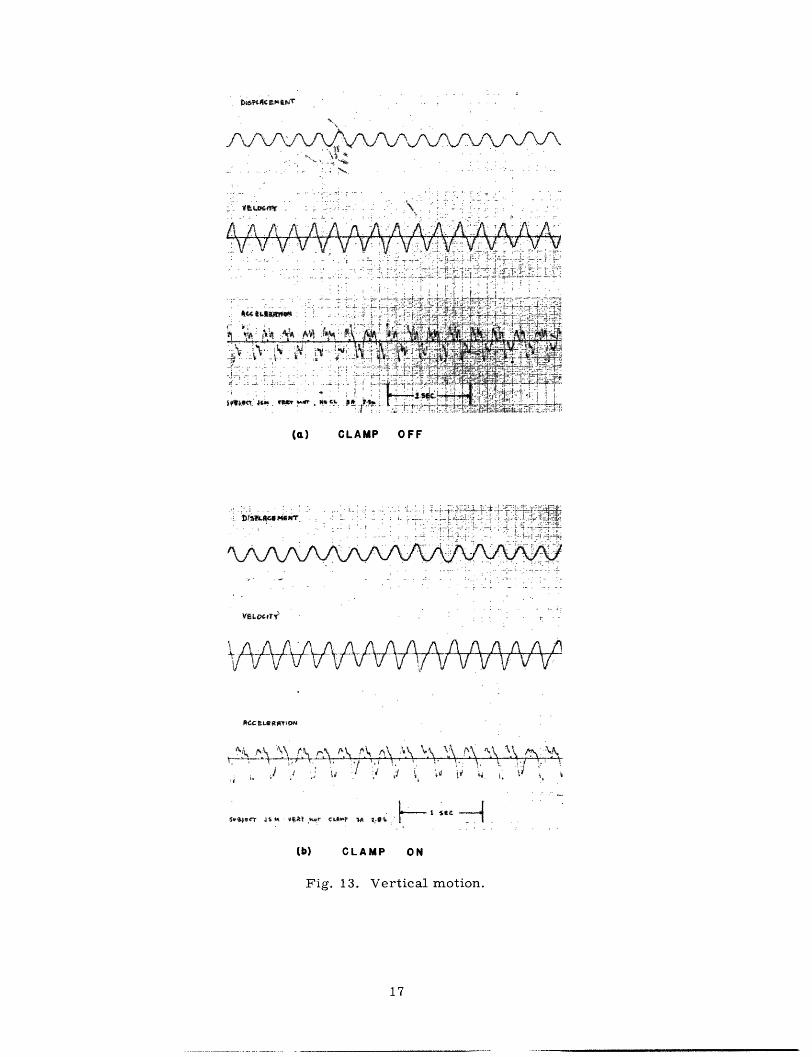
The various effects mentioned above have been identified by observation and experi-
ment. In certain cases, some of the fine structure could be eliminated by clamping the
pencil tightly to the finger, thereby greatly reducing the relative motion of the pencil
and the hand. This effect is shown in Fig. 13 for vertical motion (Subject JSM). The
amount of fine structure attributable to this source was found to vary, the amount
depending on the position of the hand, the way of holding the pencil, and the individual
subject involved. The order of magnitude of force represented by the changes of
acceleration referred to in Fig. 13 as fine structure is not large enough to be sensed as
a pressure change on the pencil grip. One can barely detect the pressure change caused
by the effect of static friction, and the fine structure is less than one-third of the magni-
tude of the spikes resulting from static friction.
2.4 EXPERIMENTAL RECORDS - HANDWRITING
Examples of the displacement, velocity, and acceleration records of actual hand-
writing samples appear in Figs. 14-17. Figure 14a shows the vertical displacement,
velocity, and acceleration together with horizontal acceleration, while Fig. 14b shows
horizontal displacement, velocity, and acceleration, together with vertical acceler-
ation. Figure 14c is the vertical displacement as a function of horizontal displacement.
The layout of Figs. 15, 16, and 17 is the same as for Fig. 14.
The effects of static friction are in evidence throughout the records. In Fig. 14 we
see an example. The arrows in Fig. 14a point to a static friction spike. In Fig. 14b the
arrow on the h'(t) waveform shows that the horizontal velocity is zero as expected for
static friction.
The horizontal and vertical acceleration waveforms appear twice in the records
associated with each sample. One pair of acceleration signals for each sample has
trapezoidal approximations fitted to the waveforms. The other pair is left untouched.
The reason for doing this is so that one can see the detail of actual acceleration
16
__
LPt~w CmINT
: -
.A . A' A_..l. .. '-":A -A'.
.4 'c t. , .a .......... : .. .. 4...
e·u'. k. '. i.'Xt.
-- ,;' '. ' ' ' .... . . . q. . .'-; -.. ' '-- ', - , . Y f: i- "~ '* t
'
.
.. . .- v
I ·i ~ : ··. '
Sle t t $ tE -,rr CAtV W A 2AftC F t .
(b) CLAMP ON
Fig. 13. Vertical motion.
17
.-. . . .. _ --

tlO
Iv~7 I
. .I*~~T~i s~c1~~~~~4t~~~~~~b~
(a)
i ko
-A A J . t , '.i ; y ,4 C·w
i $ cr
if l SEC.
'4
.' i I v
(b)
(c)
Fig. 14. Handwriting sample, Subject HJZ.
18
Itot
11~ a al ' 4 '0

4-.'A~~~' I--- Il u I--
lvfI
I -~
S~X W;il~a~~~~~~~~~~~~~~f l
.1E I _
(a)
18wig~~~~~ A
ST -. . . 4
Athen IW P(b)
(c)
Fig. 15. Handwriting sample, Subject VG.
19
I- I- - - '��--- I pi II_. -�--�II I-P- ^-�··---_111IIII_- �-�

-AfrIVj7-
;uir i6
2: ,~~~ i4~..
.( .
i4 l.#t ·,
., .. . X.+
.. .. ~~.. -: v ----
t 6 - ~~~~~~~~~~., i... W .s
.t .< .i i -< r· t
_d .... ,li~r, , X
I ; _~ ,I . - ;-\ .
-.. ;_F+* ,t
_ ,· .1. ..1 ·' } . .w . ,,j
sec--{I I '
kAh lP
(a) (b)
(c)
Fig. 16. Handwriting sample, Subject EGB.
20
A I t it I I I I- U -�v 1.1 I I X^
_I - . -_ e ' I- o
_ 1 �
---- J
,Wr(V
"W Q4 Iji
I "..t y-
. , "v

I�Y
v At
2 ".I 'a i
-.19,11 N~
Amw_4j~WA~u
(a) (b)
(c)
Fig. 17. Handwriting sample, Subject JSM.
21
___�I_ � II I I
-- · �@v*�L�7WS-

Iv w^ ve-t-.N-- \ \J
St a'~fT t L: a t · t
WILA)
;- -9 I '_ktt Jt U;
I'I
(b)
(C)
Fig. 18. Handwriting sample, Subject TGK.
22
Cf:i i1 SE1 E >C 5(JzW CT T t-
(a)
lo
Ov 4 v-Wr -t t

sUbt PQ
I2M
^A , A -
I N I t iVr VV '
-,¢v, .;¥u
tottAi -
lf~~~~~Zt
1>~~~~Y
vi- -f vi 7 v
i ., I-: -~--I A i rt5§C ,~~~~~~~~~-1· _ .- · --i· ·----- · ; -r?·1, '· ' ,i '· ''_ ~~~~~~~~~~~~~.:r i· ··
(c)
Fig. 19. Handwriting sample, Subject PCQ.
23
V't\tA
*
(a) (b)
_. P..o

f.-* ga ··
k ' s -.
4>s 4Wf PEp asw~ ~ ~W.,~I
(b)r.-r I . ia" ',~ ~ ; ,? .BI - ..
d- . . ..
.F .l v ,agp i._ , .'_ .
P ·. * . > . . , f
" 9t:.- · kft
i- ~ ~ .~. - ...
* +> --- ~ .rw ,ZL -,
(b)
~; fl~:%
lr
nctMaa
w~r:I ~e t *tg w.r
(d)
wit at.
~~~~~.. r. .
.Aw~~ 4~~A . .... . W.. .C Cc; .> . z ,c),rtfN feaif%.
_ * z , - .,. y ,ci~'i~*
,~ ~ ~ ~~· ... . ... . .... .. ..
.~~E .1a
-· .' v : ·I _ M.
(C)
.,5
flit bt.z_ _
',l , . ..............
. k i~r .LeT ~O
' st btk~
--,
(e)
Fig. 20. Handwriting samples - five additional subjects.
24
(a)

waveform from which the trapezoidal approximation was made.
The technique for fitting trapezoidal approximations to the acceleration waveforms
is largely intuitive, but some general guidelines can be given: Use the zero crossings
as a guide to segmentation. Ignore small variations having durations of the same order
as the static-function spikes. Ignore static friction effects. It is often helpful to refer
to the velocity waveform when constructing a trapezoidal approximation to the acceler-
ation waveform.
The next three figures, Figs. 18, 19, and 20, are further illustrations of the trape-
zoidal approximation to the acceleration of handwriting movements.
2.5 EXPERIMENTAL RECORDS - SPEED OF MOVEMENT
This section is concerned with the various aspects of slow and fast hand move-
ment. Specifically, we shall consider a simple left-right motion of the hand about the
wrist joint as the frequency of the movement is increased. This movement was chosen
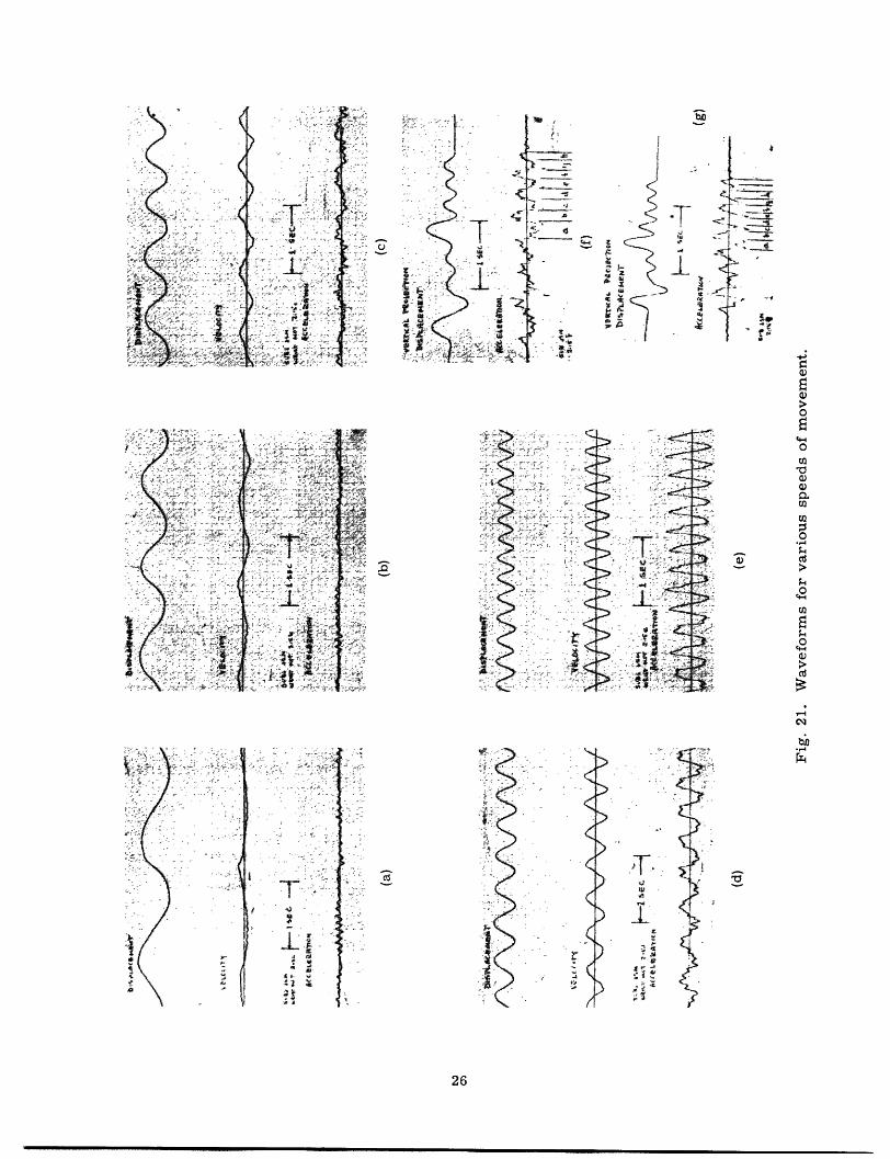
as an example because it is easy to control and is a simple basic movement. Figure 21a,
21b, and 21c displays various sections of a continuous record of movement with steadily
increasing speed. The entire record was taken with the pencil lifted to eliminate the
effects of static friction. Figure 21a and 21b shows the displacement velocity and
acceleration of wrist movement for relatively slow movement. Notice that the acceler-
ation is very "pulselike," and the control is apparently discontinuous. In fact, the
acceleration waveforms in these two records are quite amenable to trapezoidal approxi-
mation, although each section of the trapezoid is very short and contributes very little
to the displacement as contrasted to those trapezoidal sections shown previously.
Figure 21b shows the beginning of the trend of the small trapezoidal segments of the
acceleration waveform to form a larger trapezoidal pattern, in that they are alternately
predominant above and below the zero axis. Figure 21c shows the transition to this
situation in the place near the end of this record where the fine structure in the acceler-
ation waveform alternates above and below the axis, giving the over-all appearance of a
large trapezoidal wave. As the speed of movement continues to increase, there is a
quite sudden transition to a "clean" trapezoidal wave. This transition is shown in
Fig. 21d where the acceleration waveform toward the end of this record is of the nature
of those found in handwriting. Figure 21e shows the transition from conventional trape-
zoidal form to a more triangular-shaped waveform as the frequency of the movement
reaches its highest value. The frequency at this point is approximately 4 cycles, and
although one can go a cycle or two faster than this, there is no change in the basic
shape of the waveforms beyond this point. Movements of the type depicted in Fig. 21a
through 21c will be referred to as "continuously controlled movements," while those in
Fig. 21d and 21e will be called "stroke-controlled" movements. The inference here
is that slower movements are controlled in semicontinous fashion (as in a sampled-
data system), whereas fast movements are controlled on a stroke-by-stroke basis.
Examples of both types of control of movement sometimes occur in the same
25
___ _ _ _ ___�_·I__ II 11 1111111
I
I
I. k- ~ f- ; ?
. 1 . ..v. _ + . ?L a .. J _. wX "', 1 w A . ff *
i.a r··-l
·;·.··r
icE:�F· - .
·̀(_x··��··�··
fi rc�P·, "
4-( - · '
-1C"si; C-~;:7-
. - t. * r-
.- 1,x , ._
: ., ·. ff .rs
'· ' ; -' ' .
. . '. · '
. , 'f
rl y
9$- ' .
-
f
-t T
1J .. .
-'d0 7
-.
-ILt-C
.....i,
CC
-CC
.i. .,; ..
X i ' . ...'' S r ............ _
-·rlt~ ~ , 9 ,,, X ...
,, ,,C~' 's r-i . .. f
.-- ·- . · ,; .
2d
KK
rC
:>-; .. .,.-
.44- . _· ; ' -h
Ž' " I t-''-
-'- '>
)
26
IrZl,
J.1! s'tI
I
- '-C
, 4
1
S-j I
$4~i C1.a I
Q)
.l
(3)0
a0
o0
Cd
c,,1Co
--4
____ __
�s'"
�eii:
r
�spr*r·�. i:;"�rc-�l
.a
I; -r
-·-·
1·
-·
j···
:'·::-:
i
r .;·
i
i.
.,··

handwriting sample. Such a sample appears in Fig. 21f. Here the subject tried to write
"John" as slowly as possible. The vertical projections of displacement and acceleration
are shown. Continuous control is in evidence in the first part of the sample, while the
last part is stroke-controlled. Section "a" of the stroke-controlled portion represents
the transition from one type of control to the other (as in Fig. 21d, as the speed of the
writing increased slightly throughout the execution of the sample). Figure 21g shows the
same word written as fast as possible by the same person. The last part of the word is
segmented to correspond to the segmentation of the stroke-controlled portion of Fig. 21f.
The two extra segments occur because the last letter turned out to be an "m" instead of
an "n", but that is what happens when you hurry. Both of these records were taken at
the same time with the pencil lifted to reduce the effects of friction.
The records presented in Fig. 21 show that the acceleration of carefully controlled
movements can be approximated by trapezoidal waveforms independently of the speed of
the movement, but there are two distinct types of control of that movement; that which
we have called "continuous" and that which we have called "stroke." Furthermore,
there is a fairly abrupt transition between the two types of control, which depends on
the speed of the movement. This fact indicates that the nervous processes controlling
slow and fast movements may be quite different.
2.6 ACCELERATION RISE TIMES FOR VARIOUS MOVING MEMBERS IN A SINGLE
SUBJECT
A close correlation has been observed between the size of the member (and hence
the musculature) that is being moved in a particular motion and the rise time of the
trapezoidal acceleration waveform.
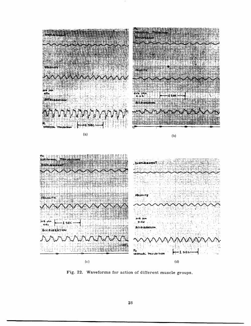
Figure 22 illustrates this very well. The four sets of waveforms shown there were
made by the movement of certain specific parts of the anatomy. Figure 22a is to-and-
fro motion of the fingers holding a pencil. Figure 22b is a record of motion of the
fingers from left to right while holding a pencil. In Fig. 22c, motion is about the wrist
joint. That is, with the fingers held rigid, the hand is swung from left to right.
Figure 22d shows waveforms obtained when the entire arm is moved to and fro (i.e.,
rotation about the shoulder joint).
The rise time of the acceleration waveforms is seen to increase with increasing
size of the moving member. The rise time of the acceleration in Fig. 22d, which arises
from the large muscles acting upon the shoulder joint, is approximately 1/10 of a second.
This rise time is so long that for the repetition rate of the movement shown, the trape-
zoidal wave degenerates into a triangular wave.
2.7 COMMENTS ON EXPERIMENTAL RECORDS
The results displayed in Figs. 9 through 20 are typical examples taken from a large
number of samples. In all, 14 people are responsible for the samples of simple motions
and handwriting presented here. Each of the 11 samples of handwriting in Figs. 14
27
_____ _·II I1_�___�_·11_·_ __� ·_ ·_ _ ___I I---�L-�-�l
(a) (b)
ii t -- ' _..;:
:
.r , .; .. .- . 7-: .: :'.: 4 '^-'-c';-. -.", < ' - -'.'.. t. ', '.-'.'%.-, o , ."V .f" "1 ' -¥. , ..
.r . . . .. ... ..r. . . .-.
,,,, ~~~~~~... . .. :. ....*. : ...... .-. .. .... ,;%,.',-- ;. ' .c. , :;....... ... , .,?- . ..v .. .;,
P/ _'. :,/ - '" ' .__~.'-; ..... _" .*. -.... ~ .~ ~ '_ '~ ' '. *- .- .. , :Z'.;'
r,- r -t ,., .-...... .. * .,.'r
.i ' -;. -',:.': -.' .. .
-: F . -'--4 4 . ..s v .j , ·. .
, " ' '4 .
~- ~~~- ---ws;C -cL~-~~- ---"vrA v'ciSlm r"- j.r ' "
(c) (d)
Fig. 22. Waveforms for action of different muscle groups.
28

through 20 is from a different person.
The dominant aspect of the acceleration waveforms in these records is the zero
crossings, which indicate a significant change in applied force. Figure 23a shows a
typical acceleration waveform. The zero crossings referred to are marked "x".
Figure 23b shows the same waveform with a trapezoidal approximation. The con-
siderable irregularity of the "flat" part of the acceleration waveform has been ignored
in making the trapezoidal approximation. How much of this fine structure, if any, is
attributable to the function of the biological system and how much is due to friction and
other mechanical phenomena is a question that cannot be answered here. In making a
trapezoidal approximation, we are assuming that the fine structure is not important to
handwriting, and all that really matters are the large abrupt changes in the acceler-
ation. The simulations to be presented in Section III support this assumption.
Concerning the possible effect of dry sliding friction: If sliding friction is signifi-
cant, then the portion of the acceleration waveform following a static-friction spike
should be lower in absolute value than the part preceding the spike, since the direction
......~~~ 9. *jr ~ ,t~ ..0n E S -.: ... ....a.* ....a S ,A., i-,~. .'~ _:.~ _ . ~ . ." ~ " , A '-~ ~ ' t~~, ~ .' .'' "- ~ ,4' ' , if t/'l X ,tr iv I ~d 14" p .~Y;kk~1$5: ~lnC :"a · r pl ^' , - . % : : ",.- -- -·· r/ ·
-ii ~~~~~~~~~i(a);···· . . , 2 ...._·· /i- : _ , l'. _.>. .. , . _. _,~ . ,._&._,.'._.4__._ . ..H ,__ r· _ , , . ._
. ~~~.
(a)
,i
"'
·- · ··. - - - - ·· · - �P··il "-: ·i··-;i ��·' ·'·. i I i ...!
2-ss'td "� ·:·
htll·k �r*r�x
(b)
Fig. 23. Typical acceleration waveform.
29
r (1 :
··
.. . a
4:ri �%Ca;rs? il,�i�n� ·i�·il:tiiti��: �I�;:·I :s r
vvt

of velocity is reversed and sliding friction is opposing the motion. Of 109 occurrences
of static friction spikes in 30 samples of handwriting, only 49 were found to exhibit the
above-mentioned behavior. We thus conclude that either sliding friction is not signifi-
cant or the human system somehow compensates for it immediately.
The results presented in section 2.4 also show that the acceleration signals have
more than two levels. If we allow that the two independent directions assumed by
Denier van der Gonl are not the ones that we have chosen to record, then we would get
a maximum of 4 levels in any direction. This is illustrated in Fig. 24, where two non-
orthogonal independent directions have been chosen and two arbitrary levels set off in
each direction. It is easily seen from the figure that there are at most 4 levels pro-
jected onto each of the horizontal and vertical axes.
FOURLEVELS
VERTICAL FF2
INDEPENDENTDIRECTIONS
OF ACTION
K~ \
FiL
FOUR LEVELS
F2 H F1
- F2L
F1H
HORIZONTAL
Fig. 24. Projections of two-level forces.
Inspection of Figs. 14-17 reveals that in general there are more than 4 levels in
each of the acceleration waveforms. Even in Fig. 19, which is a sample of lelele, we
find more than 4 levels in the acceleration waveforms. Figure 18 is a fairly uniform
sample of lelele, and it comes closer to satisfying the two-level assumption. Thus we
see that some samples of lelele do have nearly the same force on all segments of the
trapezoidal wave, but this is a particular case rather than a general truth for hand-
writing.
30
___ __
~~~ ---------~~~~~~~~~~~~~~~~~
1
r
-1
III. A SYSTEM THAT SIMULATES HANDWRITING
3.1 INTRODUCTION
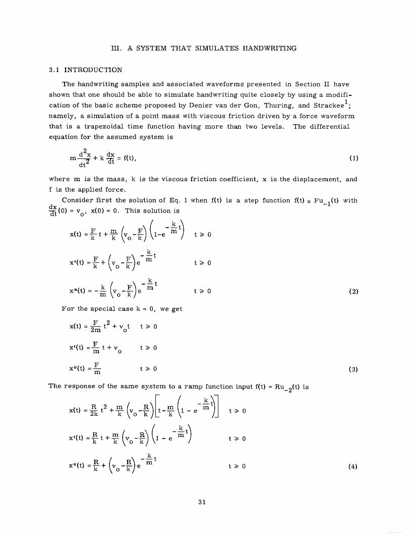
The handwriting samples and associated waveforms presented in Section II have
shown that one should be able to simulate handwriting quite closely by using a modifi-
cation of the basic scheme proposed by Denier van der Gon, Thuring, and Strackee 1 ;
namely, a simulation of a point mass with viscous friction driven by a force waveform
that is a trapezoidal time function having more than two levels. The differential
equation for the assumed system is
m2+k f(t),dt
(1)
where m is the mass, k is the viscous
f is the applied force.
Consider first the solution of Eq. 1dxt (°)= vo0 x(O) = 0. This solution is
x(t) = kt + - 1-e m
k tx'(t)= +/ m
k mx"(t) m ( e mo- e
friction coefficient, x is the displacement, and
when f(t) is a step function f(t) = Fu_l1(t) with
t >_ 0
t 0
t 0 (2)
For the special case k = 0, we get
F t 2x(t) = ~-t + v° t _-02m 0
x'(t) = F t + vm 0
x"(t) =Fm
t 0
t>_ (3)
The response of the same system to a ramp function input f(t) = Ru_ 2 (t) is
R2 mx(t) = t + - e t > 02k k 0 k m m
t 0
t 0 (4)
31
-
k mk 0 k
-k X11(t) R + Re

For the special case k = 0, we get
R 3 Vo t2
x(t) = 6- t + t t 0
R 2x'(t) = t2 + v t>_ 0
x"(t) = R t t > 0
The response of the
Eqs. 2 and 4. Figure 25
system to a trapezoidal input f(t) is easily constructed from
is a plot of a typical solution.
Fig. 25. Solution of Eq. 1 for trapezoidal f(t).
A physical question arises concerning the inclusion of the effect of friction in the
system. The records in Section II show the effect of static friction quite plainly, but we
have chosen to ignore it. Dry sliding friction was discussed in section 2.7 and found to
be negligible. Neglecting the effect of static friction, one is left with an uncertainty of
approximately 25% of the mean height for the trapezoidal wave's flat top in the experi-
mental records. There is no definite trend in the droop of the trapezoidal wave, so this
gives us a bound on the droop of -25% over the duration of the longest segment. Let T
be the duration of the longest segment of the trapezoidal wave in seconds, then for 25%kT
droop, em 0.75, and kT= 0.29 or = This gives an upper bound on . inm m T terms of T:
32
(5)
011
oe,IT
'001-*4'00,
T-S4.-
M ==mm PO
__

k <0.29 (6)m T
Typically, T = 0. 12 sec, so this gives k 2.42. This figure is only a rough upper bound,~k m
and the ratio k may, in fact, be much lower.
An electronic simulator has been constructed which mechanizes Eq. 1 where the
trapezoidal wave f(t) is allowed to take on a continuum of amplitude values. This simu-
lator, its adjustment, and some of the experiments in which it has been employed are
the subjects of this part of the report.
3.2 THE SIMULATOR
A functional block diagram of the handwriting simulator appears in Fig. 26. The
simulator consists of two principle parts: the linear system which simulates Eq. 1 and
provides for independent adjustment of m and k, and the trapezoidal wave generator
which provides the "force" signal f(t). The use of an oscilloscope for displaying the
Fig. 26. A handwriting simulator.
output of the system requires two linear systems and two trapezoidal-wave generators,
one for vertical deflection and one for horizontal deflection. A synchronizing system
provides the start pulse for the trapezoidal-wave generators, and the reset signals to
discharge the integration capacitors in the linear system.
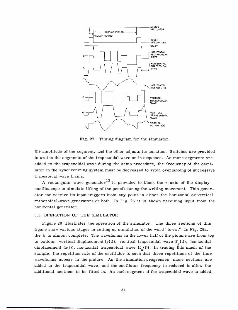
Operation of the simulator is as follows: The synchronizing system contains an
oscillator that generates integrator reset signals at a frequency that can be set by a
front-panel control. The integrator reset signal is of 5 msec duration (reset interval
or clamp period). The start pulse for the trapezoidal-wave generators occurs at the
end of the reset interval (see timing diagram, Fig. 27). This start pulse initiates a
burst of trapezoidal waves from each trapezoidal-wave generator. Each segment of the
trapezoidal wave can be varied by two controls in the generator; one control adjusts
33
MASTEROSCILLATOR
DISPLAY PERIOD
CLAMP PERIOD
RESETINTEGRATORS
START
HORIZONTAL
~~0 _ 2X~~~~~~ RECTANGULARWAVE
H ORI ZO NTALTRAPEZOIDAL
/ WAVE
HORIZONTALOUTPUT x(t)
O VERTICALRECTANGULARWAVE
O~~~ -H~~~~~ _ =VERTICALTRAPEZOIDALWAVE
VERTICALOUTPUT y(t)
Fig. 27. Timing diagram for the simulator.
the amplitude of the segment, and the other adjusts its duration. Switches are provided
to switch the segments of the trapezoidal wave on in sequence. As more segments are
added to the trapezoidal wave during the setup procedure, the frequency of the oscil-
lator in the synchronizing system must be decreased to avoid overlapping of successive
trapezoidal wave trains.
A rectangular wave generator 13 is provided to blank the z-axis of the display
oscilloscope to simulate lifting of the pencil during the writing movement. This gener-
ator can receive its input triggers from any point in either the horizontal or vertical
trapezoidal-wave generators or both. In Fig. 26 it is shown receiving input from the
horizontal generator.
3.3 OPERATION OF THE SIMULATOR
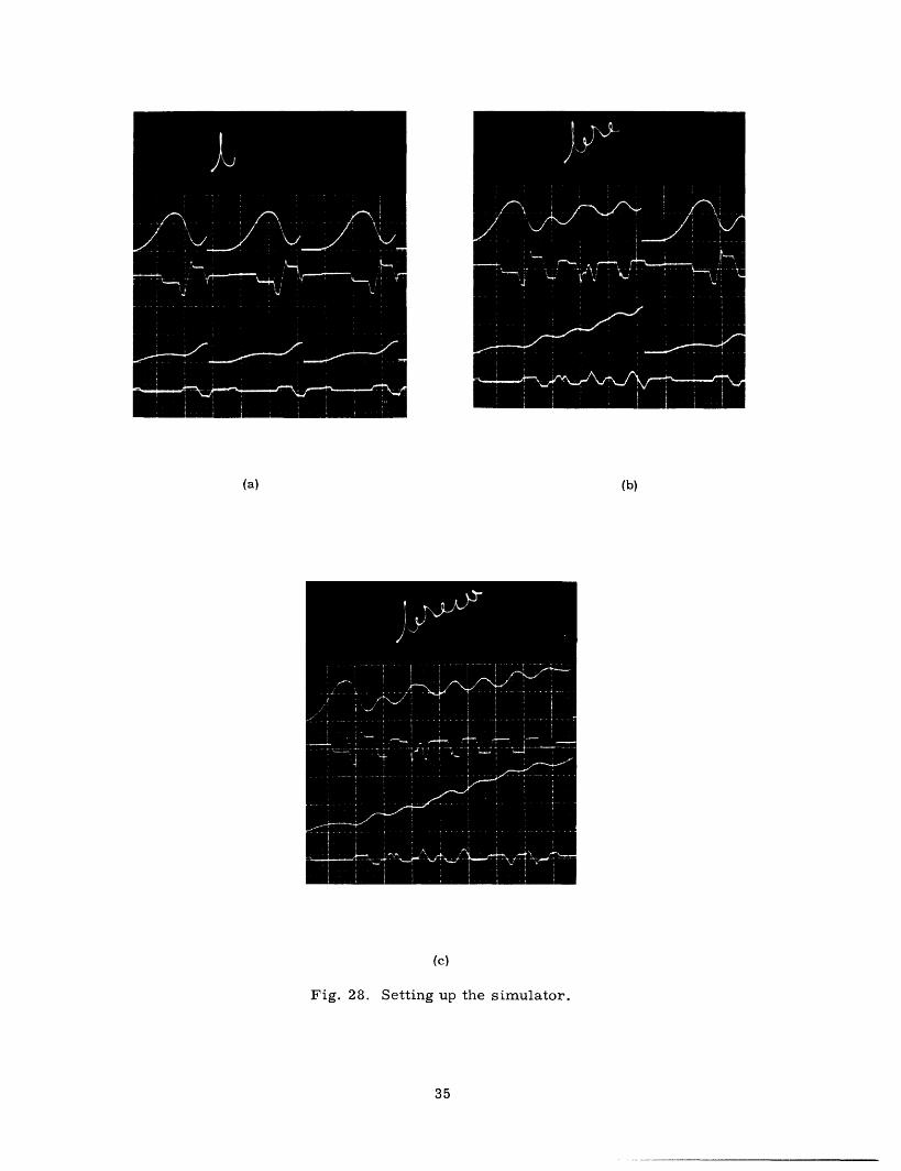
Figure 28 illustrates the operation of the simulator. The three sections of this
figure show various stages in setting up simulation of the word "brew." In Fig. 28a,
the b is almost complete. The waveforms in the lower half of the picture are from top
to bottom: vertical displacement (y(t)), vertical trapezoidal wave (f (t)), horizontal
displacement (x(t)), horizontal trapezoidal wave (fx(t)). In tracing this much of the
sample, the repetition rate of the oscillator is such that three repetitions of the time
waveforms appear in the picture. As the simulation progresses, more sections are
added to the trapezoidal wave, and the oscillator frequency is reduced to allow the
additional sections to be fitted in. As each segment of the trapezoidal wave is added,
34
(a) (b)
(c)
Fig. 28. Setting up the simulator.
35
__ ___�_�I�

it is adjusted in both duration and amplitude to make the resulting output correspond as
closely as possible to the pattern that is being copied. Figure 28b shows completion of
"bre", and Fig. 28c shows the completed simulation. The time and amplitude scale
factors in all three pictures in Fig. 28 are identical.
When copying a specific sample of handwriting, the sample is recorded on trans-
parency film or thin paper, and is inserted into the projected graticule attachment on a
Tektronix C-12 oscilloscope camera. A ground glass on the back of the camera then
has the image of the sample superimposed upon the image of the trace on the oscillo-
scope. The simulator is adjusted to make the two images coincide.
3.4 SIMULATION OF HANDWRITING
Figures 29-32 display the results of simulating the four samples displayed in
Figs. 13-17. In each of these, the trapezoidal waveforms were set up to match as
closely as possible with the trapezoidal approximation to the actual acceleration. The
trapezoidal waves were then trimmed to give close match between the output and the
original sample.
The leading and trailing slopes of the trapezoidal waves are independently adjustable,
but there is no independent adjustment for each segment of the wave. Inspection of the
records presented in Section II clearly reveals that the slopes on the various segments
of the trapezoidal waves are not the same. This, together with the fact that the effect of
static friction is neglected, accounts for the most noticeable discrepancies between the
original and simulated handwriting.
Figure 29 is a simulation of the word "brew" displayed in Fig. 14. In Fig. 29a, the
top word is the simulation, the bottom one is the original word as written by the subject.
Figure 29b shows waveforms taken from the simulator which correspond to those of
Fig. 14a. The effect of the uniform leading slope required by the simulator can be seen
as a more rounded tip on the first negative peak in the vertical velocity waveform v'(t)
in Fig. 29b than appears on the same waveform in Fig. 14a. This occurs because the
slope on the vertical acceleration waveform is too low at this point. On the other hand,
the fifth positive segment of the vertical acceleration waveform of Fig. 29b is wider
than it should be because the slope at this point is too large compared with the actual
waveform of Fig. 14a. Figure 29c shows the set of simulator waveforms corresponding
to Fig. 14b.
Using Figs. 14 and 29, together with the settings of the linear system in the simu-
lator, we compute an equivalent value of k for the simulation of Fig. 29 to be
k- 2.88.m
From Fig. 15, the duration of the longest segment 0.13 second. Hence, according to
Eq. 6,
k 0.29m = 2.2.
36

(a)
(b)
HORIZONTALSCALE
5 ms/largedivision
J
(c)
Fig. 29. Simulation of sample of Fig. 14.
37
_______�I� I

(a)
(b)
HORIZONTAL SCALE
5 ms/la rge divisi on
I
Cc)
Fig. 30. Simulation of sample of Fig. 15.
38

(a)
(b)
HORIZONTAL SCALE
5 ms/largedivision
I
(c)
Fig. 31. Simulation of sample of Fig. 16.
39

(a)
(b)
HORIZONTALSCALE
6 ms/largedivision
4
(c)
Fig. 32. Simulation of sample of Fig. 17.
40

Thus the friction in the simulation of this example is slightly exaggerated. The droop
on the acceleration waveforms of Fig. 29 is still not too pronounced, and there is no
noticeable sag on the rises of the trapezoidal wave. It is clear that one could fit a wave-
form having about this much droop to the acceleration waveforms of Fig. 14a just as well
as the one having no droop which has been fitted in this figure. The conclusion is then
that all we can say regarding the characteristics of the linear system in the model is
that k has an upper bound of 0.29, where T is the duration of the longest segment.m T' k
It has been observed that the value of does not seem to affect one's ability to
simulate a given sample. Figure 30 is a simulation of the word "brew" by a second
subject, and it corresponds to Fig. 15. The linear system settings for this simulation
are the same as the ones used in the example of Fig. 29. In Figs. 31 and 32, we have
simulations of the word "fell" written by two different subjects, which correspond to
Figs. 16 and 17, respectively. The value of k set on the linear system for these simu-
lations was zero! The layout of the figures and the comments that one can make about
them are the same as for Fig. 29.
The four samples shown in Figs. 14-17 are written by four different people. It is
particularly interesting to consider the physical characteristics of the subjects writing
"fell" in Figs. 16 and 17. One of these is a tall man with large hands, while the other
is a shorter man with significantly smaller hands. The linear system is associated
physically with the mechanical properties of the hand, arm, and pencil. Since these
two samples were written with the same implement, one would expect any discrepancies
attributable to physical causes to show up on these samples. Both samples were simu-
lated by using exactly the same settings of the linear system, and both simulations were
equally successful. We can conclude from this that the mechanical parameters are notk
especially significant in the simulation of handwriting, as long as the bound on
established in section 3.1 is satisfied. Actually, experiments with the simulator have
shown that good simulations can be achieved with k values considerably exceeding this
bound, but the records in Section II indicate that the parameters associated with most
individuals fall well within this bound.
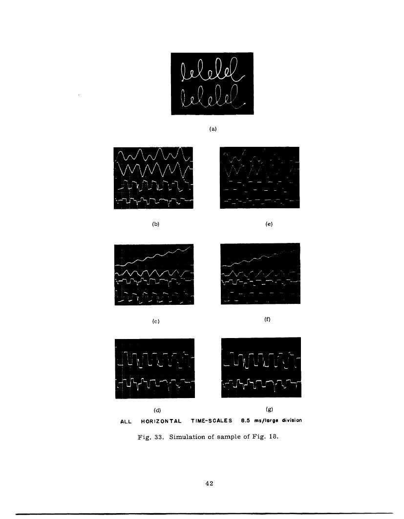
Further evidence of the effect of k on handwriting simulation is presented in Fig. 33.
Figure 33a shows the result of simulating the record of Fig. 18. Figure 33a and 33c
shows the resulting time waveforms. The equivalent value of k in this simulation is 3.1.mFigure 33e and 33f shows the time waveforms for the same simulation with an
equivalent value of k of 0.364. The output of the simulator for this lower value of kmm
was the same as for Fig. 33a. Figure 33d shows the input trapezoidal wave for the
simulation with k 3.1, and Fig. 33g shows the input trapezoidal wave for simulation
of the same sample with = 0. 346. In both of these figures, the top trace is the inputm
to the vertical channel, and the bottom trace is the input to the horizontal channel.
Inspection of Fig. 33 reveals that the timing and amplitude of the trapezoidal input
waveforms differ little in the two cases. Adjustments required to compensate for the
change in the value of k from 3.1 to 0.364 were very minor, but if one examines them
41
(a)
(b) (e)
(c) (f)
(d) (g)
ALL HORIZONTAL TIME-SCALES 8.5 ms/lorge division
Fig. 33. Simulation of sample of Fig. 18.
42

trapezoidal waveform closely, the changes are evident; the amplitudes of the segments
tend to be very slightly less in Fig. 33e than the peak amplitudes of Fig. 33b, and the
duration of some segments is slightly longer for the larger value of k . The effect ofm
having a uniform slope on the trapezoidal waves is especially pronounced; compare the
negative peaks of v' in Fig. 33 with those of the actual handwriting sample of Fig. 18.
Some of these negative peaks are decidedly less rounded than the original. This, of
course, is traceable to a much steeper slope in the trapezoidal acceleration waveforms
of the simulation at those points.
3.5 SUMMARY
We have presented a description of the handwriting simulator and its operation,
together with some examples of its output. We have shown that the use of a multi-
level trapezoidal wave enables us to achieve very good duplication of handwriting
signals.
One can gain some idea of the accuracy of the simulator insofar as its ability to
reproduce handwriting waveforms is con-
cerned from Fig. 34. Figure 34a shows
the displacement, velocity, and acceler-
ation of the vertical projection of the word
"fell" written by a subject. The simulated
version appears in Fig. 34b superimposed
upon the image of Fig. 34a. In this simu-
lation,
k = 1.14m
which is well within the bound of 1.81 set
by inequality (6) for this sample.
Matching of displacement is within a
linewidth, and the match of velocities is
nearly as good. The example of Fig. 34 is
typical of many matchings which have been
carried out with different words and differ-
ent subjects. All show the excellent repro-
duction that the simulator achieves.
The samples just displayed are simu-r .
1 i .I i~~~ V~
(b)
Fig. 34. Accuracy of the simulator
lations of the actual samples taken as
described in Section II. They show thek* result of varying . over the range of the
bound established for this quantity in
section 3.1, and illustrate the fact thatk
the effect of - on the settings of the
43
(a)

trapezoidal-wave parameters is small. We have also seen that linear systems with
widely different ratios ofk (including zero) can be caused to have matching outputsmthrough adjustment of their inputs.
44

IV. MODELS FOR THE GENERATION OF HANDWRITING
4.1 A MODEL DERIVED FROM THE EXPERIMENTAL RESULTS
The results presented in Sections II and III have shown that uninterrupted hand-
writing curves are very closely approximated by signals generated by the simulator
described in Section III, and that the velocities and accelerations of handwriting move-
ments are very similar to the first and second derivatives of the simulator output. Thus
it is apparent that the differential equation
d2x dxm t 2 + k - t = f(t), (7)
where f(t) is a trapezoidal time function, provides an output that corresponds closely to
that of handwriting movements, and that the velocities and accelerations of the hand-
writing signal coincide closely with those derived from this simple system. The sig-k
nificant parameter in this equation is the ratio m. It has been shown in Section III thatm kinsofar as simulation of handwriting is concerned, wide tolerance on the value of k is
m
acceptable. One can measure its value from the droop of the flat tops of the acceler-
ation waveform. The records of acceleration presented in Section II show considerable
noise, as would be expected. No significant droop is observable in these waveforms.kZero droop corresponds to k = 0, and this is quite unreasonable on physical grounds,
since it implies a lossless system! The noise on the acceleration waveform is such
that it would mask a small droop. For this reason, we can only set an upper bound onk
k The upper bound set in Section III was such that the droop be less than 25% of themtotal height of the longest segment of the trapezoidal wave in the sample under consider-
ation. This bound is very conservative, and it is felt that the amount of droop is con-
siderably less than this. An upper bound of 25% on the droop is, however, all that onek
can safely conclude from the records in Section II alone. This leads to a bound on
given by
k <0.29 (8)m T
where T is the duration of the longest segment of the trapezoidal wave measured in
seconds.
The differential equation (7) is that of a point mass possessing some viscous friction
and acted upon by a force. Thus a suitable model, stated in physical terms, is a point
mass acted upon by a force that is a trapezoidal time function and may pull in any
direction upon the mass during a single segment of the trapezoidal function. The
trapezoidal waves generated by the simulator represent the vertical and horizontal pro-
jections of the total "force." An illustration of this model is presented in Fig. 35.
Figure 35a shows a point mass of parameters m, k acted upon by a force f which is
decomposed into its x and y components. Figure 35b shows a point mass acted upon
45
___

m,kfx
(a)
y
fl Ostst 1
f 2 ti <t1/f fl ~~f2 tl < t < t2
f I f 3 t2 < t < t 3• f = f '<3 4 _ at f5 f5 t4 < t < t5
f5 0 t5<tm,k 5
x
(b)
(c)
Fig. 35. Illustration of the model.
46
f (t)
fy (t)
f (t)

by a time-variant force which assumes 5 different vectoral values. No attempt is made
to show the motion that would result. The x and y projections of the force waveform
are displayed in Fig. 35c.
It is significant to note that we make no statement concerning the existence of inde-
pendently controlled directions of motion. Some subjects seem to write with two sets of
muscles, which cause motion predominantly in two nearly perpendicular directions;
while others do not. Thus the supposition of independent directions appears to apply only
in particular cases and is not true in general. In this report, we deal only with the pro-
jections of the acceleration waveforms on a convenient set of axes. The axes chosen, in
most cases, are oriented horizontally and vertically with respect to the writing line.
These axes have the virtue of having a simple and direct relationship to the writing
itself. As one moves his hand across the page while writing, the directions of action of
his musculature on the pencil change with respect to the chosen axes.
Static friction has been neglected in the model of Fig. 35; however, since its effect
is readily discernible in the experimental records in Section II, it is necessary to treat
its inclusion in the model here. The effect of static friction can be included explicitly
simply by inserting a static-friction spike in the force waveform of the simulator when
setting it up. To include it implicitly, one must sense the occurrence of zero velocity
in both projections simultaneously, and apply the appropriate modification to the "force"
waveform. Mathematically, this can be expressed as follows:
d 2x dx dMxt 2 kx = x dt f dt
2 t(9)mdy f+ k (t)- [dx dyl
where fsx(xI,yt) has the form shown in Fig. 36a, and fsy has the form shown in Fig. 36b.
In these figures, the static friction force has zero value except when both velocities are
within a small region of width, A, about zero.
Equations 9 represent a slightly more exact model for handwriting than Eq. 8
in that the effect of static friction is included. The simulator of Section III does not
include this refinement, and static friction is ignored in all of the simulations reported
in this work.
4.2 INTERPRETATION OF THE MODEL
The model presented here is based upon the results of the measurements and simu-
lations described in Sections II and III. It is apparent that the output signals predicted
by the model match very closely with those observed in actual handwriting.
Because the results upon which the model is based are measurements only of the
output of the biological system, we can infer very little from them about the internal
functioning of that system. We have seen that the acceleration waveforms of handwriting
are approximately trapezoidal. If the physical system that is being accelerated can be
47

dy/dt
FS
dxdt
(a)
dx
dt
(b)
Fig. 36. Force functions for simulation of static friction.
48
___

considered as a lumped system, then the force function giving rise to the acceleration
is also trapezoidal. The hand, arm, etc., which is the biological system responsible
for handwriting, is a mixture of lumped and distributed parameter systems. It is also
active and nonlinear. To what extent it can be represented by a lumped linear system
is a question that cannot be answered fully at this time.
If one can consider the biological system to be a lumped one, then the resultant
force function causing the acceleration is trapezoidal. But this resultant is composed
of a very complex combination of muscle forces, and it is not necessary for these forces
to be trapezoidal in order to have a trapezoidal resultant.
The rises and falls of the acceleration are directly attributable to changes in activity
in the musculature responsible for them. Thus the zero crossings of the acceleration
waveforms are useful for determining timing properties of the biological system.
4.3 SPECULATIONS CONCERNING THE CONTROL OF HANDWRITING
It has already been pointed out that one can say very little about the control of a
process by simply examining the output signal. In fact, about all that can be said about
the control of handwriting from the measurements described in Section II is that the
applied force is approximately constant over short intervals of time, and that it changes
abruptly between these intervals, i.e., the force waveform is trapezoidal. In spite of
this, experience with the simulator and observation of handwriting signals enables one
to make speculations which, though unsupported by direct experiment, are consistent
with the observed results.
Denier van der Gon has suggested1 that the control of handwriting is accomplished
by a "pre-set" sequence of signals which control the amplitude and timing of the force
waveform (see Fig. 37). The simulator described in Section III is controlled in this
fashion. In using the simulator, it was found that very slight perturbations in the
"force" waveform in the initial portion of the writing sequence cause catastrophic
changes in the rest of the sequence. This is illustrated in Fig. 38. In this figure, the
word "bell" as shown in Fig. 38a was set up on the simulator. The time waveforms
shown are vertical and horizontal "displacement" and "force." The result displayed in
Fig. 38b resulted when a small spike (such as might be caused by an obstruction on the
writing surface) was introduced in the first segment of both the horizontal and vertical
force signals. In Fig. 38c, the amplitude of one of the initial segments of the vertical
waveform was altered slightly. The reason for the lasting effect of these small changes
AMPLITUDI
TIMING
Fig. 37. Model represented by the simulator.
49

(a)
(b)
(c)
Fig. 38. Effect of small errors on model of Fig. 37.
50

is simply the long memory possessed by the system because of its low damping.
A system having the same output as the system of Fig. 37, but which is not as sensi-
tive to perturbations of its outputs, is shown in Fig. 39a. In this system, the inputs
are amplitude of force, and the displacement at which this force is required to change.
Figure 39b illustrates operation of this system. In this figure, the force level F 1 is
generated by the force generator. The resulting displacement is as shown. Sometime
before the instant tl, the level F 2 is preset into the force generator. When the dis-
placement reaches point A, the threshold detector, which has level A as its input, causes
the force generator to switch from F 1 to F 2 . Note that fixed delay in the feedback loop
can be accommodated by this system simply by setting level B, say, into the threshold
detector. In this case the delay time A would have elapsed before the force changed, at
which time the displacement would be at level A, as required.
AMPLITUDE
(a)
DISPLACEMENT
F1
F2
A
B
FORCE t1
(b)
Fig. 39. A second model.
51
J
. ~ - - - -
,_
t
t
Experiments recently reported by Denier van der Gon 2 support the validity of the
control system of Fig. 39. In his experiment, Denier van der Gon increased the friction
between the pencil and the writing surface suddenly and unexpectedly by means of
increased magnetic attraction between the two, while a subject was executing the cursive
sequence A . The influence of this friction increase was to cause the amplitude
of the writing to decrease while the writing line, however, was held constant. That is,
the base line of the sequence of 's was essentially a straight line. It was also reported
that there was no appreciable change in the time required to execute anwhen increased
friction was present.
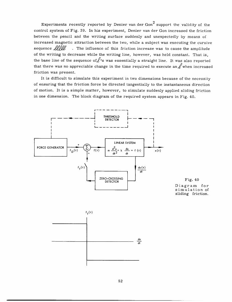
It is difficult to simulate this experiment in two dimensions because of the necessity
of ensuring that the friction force be directed tangentially to the instantaneous direction
of motion. It is a simple matter, however, to simulate suddenly applied sliding friction
in one dimension. The block diagram of the required system appears in Fig. 40.
THRESHOLD- -| DETECTOR -
lr--------!~~~~~~~~~ I
!~~~~~~~~~~~_ I
Fig. 40
Diagram forsimulation of
sliding friction.
ff(t)
dxdt
52

Figure 41a shows the resulting displacement,
velocity, and force as functions of time when sliding
friction is suddenly applied to the open-loop system
of Fig. 37. In Fig. 41a, the increased friction is
present during the brightened portion of the wave-
forms. Figure 41b shows the same set of waveforms
when increased friction is applied to the system of
1Fig. 39. In both o these simulations, the orce
(a) caused by increased friction is 10% of the drivingfran
In the result of Fig. 41a, the effect of increased
friction is not so much to decrease its size as to
distort the base line. It is also interesting to note
that the degree of "bending" of the base line and
whether it bends up or down is dependent upon when
the increased friction is applied. The system of
Fig. 39, however, exhibits behavior more similar to
(b) that observed by Denier van der Gon in handwriting.There the base line remains straight, and there is a
Fig. 41. Results of suddenFig.41. Results of sudden significant decrease in size. It is also interesting toincrease in frictionupon (a) the system note that there is only a small decrease in the periodof Fig. 37. (b) the of the displacement waveform.system of Fig. 39.
The system of Fig. 39, which has some local
feedback, thus is seen to fit the data better than that
of Fig. 37. Both systems have identical output waveforms, and are therefore equiva-
lent insofar as their ability to match the measured waveforms of Section II is concerned.
Biological mechanisms capable of providing the kind of local feedback required are well
known. 1 7 ' 1 9 The fact that the proposed system will function with fixed delay in the feed-
back loop allows for the delay present in nerve signal propagation. The principle of local
feedback is also consistent with Lashley's measurements on accuracy of movement. 9
4.4 SUMMARY
The conclusions to be drawn are that handwriting signals are quite well duplicated
by a model consisting of a point mass with slight friction driven by a trapezoidal force
function.
Questions concerning the organization of the nervous system which controls hand-
writing are not covered by this model. The model developed simply describes a system
whose output is equivalent to handwriting insofar as the displacement, velocity, and
acceleration of the movement are concerned. No conclusions can be drawn concerning
the origin of handwriting signals by consideration of this model alone, other than to say
that there appears to be a relation of unknown nature between the actual muscle forces
53

and the "force" signals in the model. Some preliminary results indicate that local feed-
back may be present, and that the trapezoidal "force" signals can be derived by discrete
preset information concerning position and force magnitude. These concepts are in
agreement with the experiments of Denier van der Gon 1 ' 2 and Lashley. 9 ' 1 0
The model in its present form is very useful for imitating handwriting with a view
to establishing the necessary invariants to characterize it. It also provides a basis for
further work directed toward studying its relationship with the biological system. The
model is also useful for studying the differences and similarities in various styles of
handwriting through simulation. Further details on application of the model are to be
found in Section V.
54
__ ___ ___

V. SUMMARY OF THE WORK: POSSIBLE APPLICATIONS AND EXTENSIONS
5.1 INTRODUCTION
We shall now give a summary of the work and consider some experiments that
constitute an initial step in the endeavor to establish relationships between the observed
acceleration waveforms and the functional principles of the biological system producing
them. Related to this objective is that of determining correspondences between the
input to the simulator (i.e., the model) and the inputs to the biological system. It has
already been pointed out (Section I) that the present report does not answer questions
concerning relations between the measured signals and the functional principles of the
organism that gave rise to them. The experiments described here are directed toward
that end, and although they are not extensive enough to achieve it, they do indicate a
direction of pursuit based upon the results of previous sections.
5.2 ELECTROMYOGRAMS OF MUSCLE PATTERNS DURING HANDWRITING
MOVEMENTS
In an effort to gain some knowledge of muscle activity during writing movements,
some electromyographic (EMG) records were taken of muscle activity in the forearm
and hand. The results appear in Figs. 42 and 43.
Figure 42 is a record of signals made by simple vertical motion. The top and
bottom traces are EMG's taken from surface electrodes. The electrodes responsible
for the top trace (1) were placed on the palm of the hand, directly over the abductor
pollicis brevis at the base of the thumb. The electrodes responsible for the bottom
trace (3) were placed on the dorsal part of the forearm, approximately 4 inches below
the elbow. The superficial muscles contributing to this signal would be the extensor
carpi ulnaris and the extensor digitorum. The center trace (2) is the vertical acceler-
ation signal. Several features of these signals are worthy of note: (i) The EMG signals
are remarkably segmented, which gives strong support to the assumption made in
Section IV that the controlling force waveform is discrete in nature. (ii) The onset of
activity in the EMG signals coincides very well with changes in the slope of the acceler-
ation waveform. Several of these are marked in the figure. The cessation of EMG
activity also coincides with reproducible, recognizable features of the acceleration
waveform.
Since the two EMG records present an incomplete picture of muscle activity,
there are many features on the acceleration waveform that are not accounted for.
Unfortunately, equipment was not available to record more than two EMG's simul-
taneously.
Figure 43 shows waveforms obtained during actual handwriting. Only one EMG is
available here, that from surface electrodes near the extensor carpi ulnaris. The
segmented character of the EMG is very evident. It is also interesting to note the
55
·111 1 0 _ _ ___ S

4i · ·~~-:"--i~a 1 -'
1'I
i r :: t : `i: i iti-i.%·:..i�e i
i: iI 1� ., ICI i 1S·· 1.
In, :I i , �:? ` ti� f ii 51''
i 6� 1.i -i ·· .L I,.., i··:::· I·: t , . ; ; j- -i:�ilt·-.E-··.--·-·: i···
c3-�rl *''' ii-- r· ·f::·r ·:.1. . ·r··,· ·, r i I:... i-·-i·-·:----·-; i: ·· ···- ·- �·· ··-.- · · ,---,1 : : :i ti"-i
· 1 t ·· � : i-"I-:· .i ::.i. ·,· t
���� · 1·i
, I r ift .i.:.I ··--x,. ;t-: r·!i .r.L�-iCb: -·-!·:i' a t · -i f ' ̂* ' ' t . i .r
- z
.'.-x
T'! i: -A S,?~i:!i!
Fig. 42. Electromyographic and acceleration waveforms, simple motion. to bend the wrist t the right. The motions involved in Fig. 43 are complicated, and an:
attempt to interpret them in terms of a single EMG would be pointless. The waveforms
presented do give strong support to the concept of discrete control of the handwriting
process.
The results presented in Figs. 42 and 43 also show the feasibility of recording a
complete pattern of muscle activity associated with handwriting movements. There are
approximately 30 muscles associated with movement of the multiple joints of the hand
alone. These muscles are all interwoven in the hand and forearm, so that the use of
needle electrodes will be necessary in order to obtain detailed inled formation concerning
motor patterns. Paillard has reported an experiment in which a subject traced a
cursive figure while EMG signals were taken from 5 coaxial needle electrodes in differ-
ent muscles. The resulting signals are segmented, but there is no acceleration signal
presented with which to correlate the activity.
56
__

N-4 , 0
ll ti
;, _ . . . ' - ~.,"7: " : . -' i L ', , _ .... . ..g ~ ~ i ··tettv } > ,S-
.;t
.i .- - ... ,* *,
, : .. . ." *t .
..i .. I ... V . -
I~!i I i' K * It H S#t*'r_ ,k ;~' It*-S
/ ti-s ...., ,~ ' . ... ~ ~,. , . , ''. -. t. ;, . o I .,, > I , * ,+ si I , . . .
t~: * -- . , .r !s aL 1e ·V s s t
Fig'. 43. lectromyog phic.. tion waeorms, ha .dwriti-g.
57\~~~~~~~ ~ ~ ~ ~ ~ i ' I > ,~.X}tS. _; 'st i-
\ . *rr w \ ..x r r ~~~. ·-.
V _> i, _ +-F;E S 9 r. .t - . t
.S ._ ·fi: F t tt o+ ' S :
- . it fs. I
.I -. t ,i' ISv a lr;: -4 1 E
Fi.43 lecrmygapi anceeainwveomhnwiig
"'~ ~~~5
XI--_--�CPI -II-.·-I - I
i ·II 1I P,

5.3 CONTROL OF SIZE OF HANDWRITING MOVEMENTS
We now consider some measurements that were made in an effort to determine how,
in terms of the model of Section IV, the size of handwriting movements is con-
trolled. Measurements show that both duration and magnitude of acceleration are
observed to change when the size of the writing movement is changed, and the change in
magnitude is most pronounced.
Consider first the waveforms shown in Fig. 44a. This figure shows the displace-
ment, velocity, and acceleration of a repetitive left-right movement of the hand about
the wrist joint. The size of the oscillatory movement was increased abruptly near the
middle of the record but the frequency remained approximately the same. This change
in size of movement is reflected chiefly by an increase in the magnitude of the acceler-
ation waveform. The durations of all of the positive segments of the acceleration signal
are virtually identical, but the duration of the negative segments does tend to increase
with the increased size of the movement as evidenced by the difference in length of the
two segments which are marked.
Figure 44b shows similar behavior. Displayed is the vertical projection of a sample
of "lelele." The difference in the magnitude of the vertical extent of an e and an 1 is
reflected in changes of both magnitude and duration of the corresponding segments of
the acceleration waveform. The samples of lelele presented in Figs. 18 and 19 show
more tendency toward control of size by duration, but there is also some variation of
magnitude in those records.
We conclude from this discussion that the size of handwriting movement is con-
trolled by both magnitude of force and its duration of application, and which one of
these predominates depends upon the subject and the type of movement.
5.4 AMPLITUDE DISTRIBUTION OF THE HANDWRITING OF A SINGLE SUBJECT
A preliminary analysis has been performed on the characteristics of the acceler-
ation waveforms of a single subject. The amplitude of each segment of the vertical
acceleration waveform was measured. A histogram of the amplitudes of those sections
of the trapezoidal wave which reached a definite level was plotted (see Fig. 45a). The
sample taken was composed of measurements of 563 levels.
The histogram, shown in Fig. 45b, shows definite peaks that indicate the possibility
of quantization of acceleration levels. No conclusions can be drawn from the result
presented here because the spacing of the peaks is less than the uncertainty in measure-
ment caused by the noise. Thus it is not clear whether the peaks are due to some
properties of the writing sample or to the method of measurement.
There is a strong possibility that analysis of this type could lead to interesting con-
clusions and increased knowledge of handwriting movements in particular, and of the
nervous system in general. Closely related experiments that can be foreseen include
the study of many samples of the same word written by the same person. Here, one
could improve the signal-to-noise ratio by averaging techniques prominent in the
58

it1 1
., .. .·",: _ J f _ . . ·v V. t _ . .-* . ^I r. .
; _ ..*, ___ ..1 c;-··' ·:xti _ rR h;~SS ·· ·- 71~i.x AtCtetst
. r j WP
(a)I * -A, IN :'. t
-1 - -
A .
su V*t.k& (-,
'
Ar-
;.I
i,ti
. i
' r~"' '. ,
.'.~ ... -
e, . ··.
:r R '
i ·
"` i (?.
A i
-Vt,"::
r ·F ,r
" "4 -, ··
t.i c"s� .. i
��33�; 8:.n :·�··· -· "-
,:·
rvii�c;
i:da"I;br Ir
f· �v" �S'� �� �
(b)
Fig. 44. Waveforms for changing amplitude of movement.
59
d .i-b, _ , r, 2., " ., X - -.
i I
i . I . I 1, I I, 8e I -
.I --

NOT INCLUDED,
INCLUDED
i/
IN/CLUDED.INCLUDED
NOT INCLUDED
(a)
I _ I - I I I
U
k)
Uu
z
-28 -25 -20 -15 -10 -5 0AMPLITUDE
(b)
ii1111. I I _ I
5 10 15 20 25 28
Fig. 45. Histogram of acceleration amplitude, Subject HJZ.
processing of biological signals. The outputs of many averaging processes
be subjected to the same processing which resulted in the graph of Fig. 45b.
could then
5.5 POSSIBLE APPLICATIONS
There are several possible applications that derive from this work. We
sider a few of these which seem particularly promising.
shall con-
5.5.1 Recognition by Machine
Among the means by which man communicates through the written word, handwriting
presents the ultimate challenge to automatic recognition of a written or printed message.
Unlike printed or typed material, the letters in handwriting are not segmented. Also,
they possess a much greater variability of form. Thus not only does one have to face
almost infinite variability which necessitates the isolation of invariants* of very general
*The noun 'invariant' is used in this report in the following context: An invariant ofa letter (or word) is a property of that letter which is common to all manifestations of it.
60
_ . . . -L 'L -z.. - -. . . . - | -
------ --

character but also one has to solve the segmentation problem on the letter-to-letter
level. This combination presents a problem of considerable magnitude.
One possible approach to solving the problem is to study the way in which hand-
writing is generated. The central idea here is that knowledge about the process by
which handwriting is produced may shed some light on means by which it can be recog-
nized. More specifically, there are certain attributes of the output signal (displace-
ment of pencil point) which are due to fixed properties of the system and do not depend
on what is being written. These attributes of the signal are irrelevant to the selection
of invariants for the purpose of using them to characterize and thus recognize what has
been written. Thus if all or some of the properties of the signal which are independent
of what is being written can be removed by suitable signal processing, the resulting
processed signal may be easier to use in attempting to understand the problem of
recognition of handwriting and, in the larger sense, the recognition problem in general.
The philosophy of this approach is a variation of the "analysis-by-synthesis" philosophy
first proposed for handwriting by Eden and Halle. 4 6
Recognition procedures for handwriting which to a greater or lesser extent make14-16
use of the philosophy of analysis by synthesis are those of Mermelstein and
Teager.21 Other important work in the field of handwriting recognition has been done
by Frishkopf, Harmon, 8 and Earnest.3 A comprehensive summary of the field is to be
found in a survey article by Lindgren. 1 1
In handwriting, the invariants required to identify the content of a sample are
present in the acceleration waveform, since the relation between acceleration and dis-
placement is unchanged, irrespective of the movement that is being executed. The
possibility exists that the acceleration waveform is more amenable to analysis than the
displacement waveform, because of its segmented character. The simulator would be
useful in this respect, in that the second derivative of its output closely approximates
the acceleration of actual handwriting.
A useful experimental program directed toward the establishment of handwriting
invariants would be to study the problems related to the development of a handwriting
simulator provided with a set of modules, each of which generates a character. This
study would place in evidence such problems as the segmentation of handwriting into
letters, the joining of the letters in various sequences, and the possible existence of
basic strokes within the framework of the principles of operation of the simulator. The
solution of these problems should lead to a set of invariants that characterize the vari-
ous letters "written" by the simulator. The project would continue by attempting to
apply these invariants to the recognition of actual handwriting by machine.
5.5.2 Neurological Studies
The model developed in sections 4.1 and 4.2 and the control systems discussed in
section 4.3 imply that the control of handwriting is "preprogrammed," that is, the nerve
signals are sent in a predetermined sequence to the muscles according to the action that
61
...__. I II_ _ _sS w As~~~~~~~·~ II- · ~ ·- (

is being commanded. There is some evidence of local feedback in the control of these
motions, but the supposition at this point in the research is that there is no instantane-
ous feedback of position information all the way to the brain. This assumption agrees
with the results of Lashley9 who found that accurate motion of the knee joint was
possible without any feedback to the brain (spinal injury), provided the motions were
rapid. It is possible that further development of the techniques used in this study can
clarify some of these matters.
5.6 SUMMARY OF THE PRESENT RESEARCH
Our main concern has been the measurement and interpretation of the acceler-
ation of handwriting and related movements. Because these measurements are made
externally on a system whose inputs are unknown, it is not possible to draw any definite
conclusions about the control of the handwriting process, other than to say that it is
almost certainly discrete in nature. Some speculations have been advanced concerning
the control of the process which are consistent with physiological knowledge, the
present measurements, and what would be required of a control system to perform
tasks such as handwriting.
62

Acknowledgment
It is a genuine pleasure to thank Dr. Manuel V. Cerrillo for teaching me how to use
and expand the knowledge gained through ten years of higher education. His influence
has broadened my professional horizons immeasurably. Special thanks are due to
Professor Henry J. Zimmermann for his interest, encouragement, suggestions, and
constructive criticism during the course of this work. I am also grateful for the contri-
butions made through helpful suggestions and criticisms by Professor Amar G. Bose,
Dr. Jerome Y. Lettvin, Professor Samuel J. Mason, and Dr. Warren S. McCulloch.
The technical assistance of the Research Laboratory of Electronics research staff,
particularly Mr. E. G. Banks, Mr. H. J. Lander, and Miss Judi Sahagen, is gratefully
acknowledged.
63
_______· 1· __1�11�
References
1. J. J. Denier van der Gon, J. Ph. Thuring, and J. Strackee, "A Handwriting Simu-lator," Physics in Medicine and Biology, Vol. 6, No. 3, pp. 407-414, January 1962.
2. J. J. Denier van der Gon and J. Ph. Thuring, "The Guiding of Human WritingMovements," Kybernetic, Band II, Heft 4, February 1965, pp. 145-148.
3. L. D. Earnest, "Machine Recognition of Cursive Writing," in Information Processing1962, Proc. IFIP Congress 62, C. M. Popplewell (ed.) (Amsterdam, North-HollandPublishing Co., 1963), pp. 462-466.
4. M. Eden and M. Halle, "Characterization of Cursive Writing," Quarterly ProgressReport No. 55, Research Laboratory of Electronics, M. I. T., October 15, 1959,pp. 152-156.
5. M. Eden and M. Halle, "The Characterization of Cursive Writing," Fourth LondonSymposium on Information Theory, C. Cherry (ed.) (Butterworths, Washington,D.C., 1961), pp. 287-298.
6. M. Eden, "Handwriting and Pattern Recognition," IRE Trahs., Vol. IT-8, No. 2,1962, pp. 160-166.
7. P. A. Einstein, "Factors Limiting the Accuracy of Electrolytic Plotting Tanks,"Brit. J. Appl. Physics, Vol. 2, pp. 49-55, 1951.
8. L. S. Frishkopf and L. D. Harmon, "Machine Recognition of Cursive Script,"Fourth London Symposium on Information Theory, C. Cherry (ed.) (Butterworths,London, 1961), pp. 300-315.
9. K. S. Lashley, "The Accuracy of Movement in the Absence of Excitation from theMoving Organ," Am. J. Physiol., Vol. 43, pp. 169-194, 1917.
10. K. S. Lashley, "Cerebral Mechanism in Behavior," The Hixon Symposium,L. A. Jeffress (ed.) (New York, John Wiley and Sons, Inc., 1951), pp. 112-136.
11. N. Lindgren, "Machine Recognition of Human Language, Part III - Cursive ScriptRecognition," IEEE Spectrum, May 1965, pp. 104-116.
12. J. S. MacDonald, "Experimental Studies of Handwriting Signals," Ph.D. Thesis,Department of Electrical Engineering, M. I. T., August 1964.
13. J. S. MacDonald, "Rectangular Wave Generator," Quarterly Progress Report No. 73Research Laboratory of Electronics, M. I. T. , April 15, 1964, pp. 135-139.
14. P. Mermelstein, "Computer Recognition of Connected Handwritten Words," Sc.D.Thesis, Department of Electrical Engineering, M. I. T., January 1964.
15. P. Mermelstein and M. Eden, "A System for Automatic Recognition of HandwrittenWords," Proc. Fall Joint Computer Conference, 1964, pp. 333-342.
16. P. Mermelstein and M. Eden, "Experiments on Computer Recognition of ConnectedHandwritten Words," Inform Contr., Vol. 7, No. 2, June 1964, pp. 255-270.
17. P. A. Merton, "Speculations on the Servo-Control of Movement," CIBA Symposium,The Spinal Cord, pp. 247-260.
18. J. Paillard, "The Patterning of Skilled Movements," in Handbook of Physiology,Section 1, Neurophysiology, Vol. III, J. Field, H. W. Magaun, V. E. Hall (eds.)(American Physiological Society), p. 1684.
19. S. Skogland, "Anatomical and Physiological Studies of Knee Joint Innervation in theCat," Acta Physiol. Scandinav., Vol. 36, Suppl. 124, 1956.
20. M. O. J. Smith, "Nonlinear Computations in the Human Controller," IRE Trans.,Vol. BME-9, pp. 125-128, April 1962.
21. H. M. Teager, "Multidimensional Visual Information Processing," in Advances inBiomedical Computer Applications (New York Academy of Sciences, 1965, inpress).
64
I __ ____ _ �� �

JOINT SERVICES ELECTRONICS PROGRAMREPORTS DISTRIBUTION LIST
Department of Defense
Dr. Edward M. ReilleyAsst Director (Research)Ofc of Defense Res & EngDepartment of DefenseWashington, D. C. 20301
Office of Deputy Director(Research and Information Room 3D1037)Department of DefenseThe PentagonWashington, D. C. 20301
DirectorAdvanced Research Projects AgencyDepartment of DefenseWashington, D. C. 20301
Director for Materials SciencesAdvanced Research Projects AgencyDepartment of DefenseWashington. D. C. 20301
HeadquartersDefense Communications Agency (333)The PentagonWashington, D. C. 20305
Defense Documentation CenterAttn: TISIACameron Station, Bldg. 5Alexandria, Virginia 22314
DirectorNational Security AgencyAttn: Librarian C-332Fort George G. Meade, Maryland 20755
Weapons Systems Evaluation GroupAttn: Col. Finis G. JohnsonDepartment of DefenseWashington, D. C. 20305
National Security AgencyAttn: R4-James Tippet
Office of ResearchFort George G. Meade, Maryland 20755
Central Intelligence AgencyAttn: OCR/DD PublicationsWashington, D.C. 20505
Department of the Air Force
AUL3T-9663Maxwell AFB, Alabama 36112
AFRSTEHqs. USAFRoom ID-429, The PentagonWashington, D.C. 20330
AFFTC (FTBPP-2)Technical LibraryEdwards AFB, Calif. 93523
Space Systems DivisionAir Force Systems CommandLos Angeles Air Force StationLos Angeles, California 90045Attn: SSSD
SSD(SSTRT/Lt. Starbuck)AFUPOLos Angeles, California 90045
Det #6, OAR (LOOAR)Air Force Unit Post OfficeLos Angeles, California 90045
Systems Engineering Group (RTD)Technical Information Reference BranchAttn: SEPIRDirectorate of Engineering Standards
and Technical InformationWright-Patterson AFB, Ohio 45433
ARL (ARIY)Wright-Patterson AFB, Ohio 45433
AFAL (AVT)Wright-Patterson AFB, Ohio 45433
AFAL (AVTE/R. D. Larson)Wright-Patterson AFB, Ohio 45433
Office of Research AnalysesAttn: Technical Library BranchHolloman AFB, New Mexico 88330
Commanding GeneralAttn: STEWS-WS-VTWhite Sands Missile RangeNew Mexico 88002
RADC (EMLAL-1)Griffiss AFB, New York 13442Attn: Documents Library
AFCRL (CRMXLR)AFCRL Research Library, Stop 29L. G. Hanscom FieldBedford, Massachusetts 01731
_ - _ . ._--1 1_

JOINT SERVICES REPORTS DISTRIBUTION LIST (continued)
Academy Library DFSLB)U. S. Air Force AcademyColorado 80840
FJSRLUSAF Academy, Colorado 80840
APGC (PGBPS-12)Eglin AFB, Florida 32542
AFETR Technical Library(ETV, MU-135)Patrick AFB, Florida 32925
AFETR (ETLLG-1)STINFO Officer (for Library)Patrick AFB, Florida 32925
ESD (ESTI)L. G. Hanscom FieldBedford, Massachusetts 01731
AEDC (ARO, INC)Attn: Library/DocumentsArnold AFS, Tennessee 37389
European Office of Aerospace ResearchShell Building47 Rue CantersteenBrussels, Belgium
Lt. Col. E. P. Gaines, Jr.Chief, Electronics DivisionDirectorate of Engineering SciencesAir Force Office of Scientific ResearchWashington, D. C. 20333
Department of the Army
U.S. Army Research OfficeAttn: Physical Sciences Division3045 Columbia PikeArlington, Virginia 22204
Research Plans OfficeU. S. Army Research Office3045 Columbia PikeArlington, Virginia 22204
Commanding GeneralU. S. Army Materiel CommandAttn: AMCRD-RS-PE-EWashington, D.C. 20315
Commanding GeneralU. S. Army Strategic Communications
CommandWashington, D. C. 20315
Commanding OfficerU. S. Army Materials Research AgencyWatertown ArsenalWatertown, Massachusetts 02172
Commanding OfficerU. S. Army Ballistics Research LaboratoryAttn: V. W. RichardsAberdeen Proving GroundAberdeen, Maryland 21005
CommandantU. S. Army Air Defense SchoolAttn: Missile Sciences Division C&S Dept.P. O. Box 9390Fort Bliss, Texas 79916
Commanding GeneralFrankford ArsenalAttn: SMUFA-L6000 (Dr. Sidney Ross)Philadelphia, Pennsylvania 19137
Commanding GeneralU. S. Army Missile CommandAttn: Technical LibraryRedstone Arsenal, Alabama 35809
U. S. Army Munitions CommandAttn: Technical Information BranchPicatinney ArsenalDover, New Jersey 07801
Commanding OfficerHarry Diamond LaboratoriesAttn: Mr. Berthold AltmanConnecticut Avenue and Van Ness St. N. W.Washington, D. C. 20438
Commanding OfficerU. S. Army Security AgencyArlington HallArlington, Virginia 22212
Commanding OfficerU. S. Army Limited War LaboratoryAttn: Technical DirectorAberdeen Proving GroundAberdeen, Maryland 21005
Commanding OfficerHuman Engineering LaboratoriesAberdeen Proving Ground, Maryland 21005
DirectorU.S. Army EngineerGeodesy, Intelligence and MappingResearch and Development AgencyFort Belvoir, Virginia 22060

JOINT SERVICES REPORTS DISTRIBUTION LIST (continued)
CommandantU. S. Army Command and General
Staff CollegeAttn: SecretaryFort Leavenworth, Kansas 66270
Dr. H. Robl, Deputy Chief ScientistU. S. Army Research Office (Durham)Box CM, Duke StationDurham, North Carolina 27706
Commanding OfficerU. S. Army Research Office (Durham)Attn: CRD-AA-IP (Richard O. Ulsh)Box CM, Duke StationDurham, North Carolina 27706
SuperintendentU. S. Army Military AcademyWest Point, New York 10996
The Walter Reed Institute of ResearchWalter Reed Medical CenterWashington, D. C. 20012
Commanding OfficerU. S. Army Engineer R&D LaboratoryAttn: STINFO BranchFort Belvoir, Virginia 22060
Commanding OfficerU. S. Army Electronics R&D ActivityWhite Sands Missile Range,
New Mexico 88002
Dr. S. Benedict Levin, DirectorInstitute for Exploratory ResearchU. S. Army Electronics CommandAttn: Mr. Robert O. Parker, Executive
Secretary, JSTAC (AMSEL-XL-D)Fort Monmouth, New Jersey 07703
Commanding GeneralU. S. Army Electronics CommandFort Monmouth, New JerseyAttn: AMSEL-SC
AMSEL-RD-DRD-GRD-MAF- 1RD-MATRD-GFXL-DXL-EXL-CXL-SHL-DHL-LHL-JHL-P
07703
HL-OHL-RNL-DNL-ANL-PNL-RNL-SKL-DKL-EKL-SKL-TVL-DWL-D
Department of the Navy
Chief of Naval ResearchDepartment of the NavyWashington, D. C. 20360Attn: Code 427
Chief, Bureau of ShipsDepartment of the NavyWashington, D. C. 20360
Chief, Bureau of WeaponsDepartment of the NavyWashington, D. C. 20360
Commanding OfficerOffice of Naval Research Branch OfficeBox 39, Navy No 100 F. P. O.New York, New York 09510
Commanding OfficerOffice of Naval Research Branch Office1030 East Green StreetPasadena, California
Commanding OfficerOffice of Naval Research Branch Office219 South Dearborn StreetChicago, Illinois 60604
Commanding OfficerOffice of Naval Research Branch Office207 West 42nd StreetNew York, New York 10011
Commanding OfficerOffice of Naval Research Branch Office495 Summer StreetBoston, Massachusetts 02210
Director, Naval Research LaboratoryTechnical Information OfficerWashington, D. C.Attn: Code 2000
CommanderNaval Air Development and Material CenterJohnsville, Pennsylvania 18974
Librarian, U.S. Electronics LaboratorySan Diego, California 95152
Commanding Officer and DirectorU. S. Naval Underwater Sound LaboratoryFort TrumbullNew London, Connecticut 06840
Librarian, U.S. Naval Post Graduate SchoolMonterey, California
-- I -- -,--~~ ~.~'-~ 1 1--^1-- - . ..

JOINT SERVICES REPORTS DISTRIBUTION LIST (continued)
CommanderU. S. Naval Air Missile Test CenterPoint Magu, California
DirectorU. S. Naval ObservatoryWashington, D.C.
Chief of Naval OperationsOP-07Washington, D. C.
Director, U. S. Naval Security GroupAttn: G433801 Nebraska AvenueWashington, D. C.
Commanding OfficerNaval Ordnance LaboratoryWhite Oak, Maryland
Commanding OfficerNaval Ordnance LaboratoryCorona, California
Commanding OfficerNaval Ordnance Test StationChina Lake, California
Commanding OfficerNaval Avionics FacilityIndianapolis, Indiana
Commanding OfficerNaval Training Device CenterOrlando, Florida
U. S. Naval Weapons LaboratoryDahlgren, Virginia
Weapons Systems Test DivisionNaval Air Test CenterPatuxtent River, MarylandAttn: Library
Other Government Agencies
Mr. Charles F. YostSpecial Assistant to the Director
of ResearchNASAWashington, D.C. 20546
NASA Lewis Research CenterAttn: Library21000 Brookpark RoadCleveland, Ohio 44135
Dr. H. Harrison, Code RREChief, Electrophysics BranchNASA, Washington, D. C. 20546
Goddard Space Flight CenterNASAAttn: Library, Documents Section Code 252Green Belt, Maryland 20771
National Science FoundationAttn: Dr. John R. Lehmann
Division of Engineering1800 G Street N. W.Washington, D. C. 20550
U.S. Atomic Energy CommissionDivision of Technical Information ExtensionP.O. Box 62Oak Ridge, Tennessee 37831
Los Alamos Scientific LibraryAttn: Reports LibraryP.O. Box 1663Los Alamos, New Mexico 87544
NASA Scientific & Technical InformationFacility
Attn: Acquisitions Branch (S/AK/DL)P. O. Box 33College Park, Maryland 20740
Non-Government Agencies
DirectorResearch Laboratory for ElectronicsMassachusetts Institute of TechnologyCambridge, Massachusetts 02139
Polytechnic Institute of Brooklyn55 Johnson StreetBrooklyn, New York 11201Attn: Mr. Jerome Fox
Research Coordinator
DirectorColumbia Radiation LaboratoryColumbia University538 West 120th StreetNew York, New York 10027
DirectorStanford Electronics LaboratoriesStanford UniversityStanford, California
DirectorCoordinated Science LaboratoryUniversity of IllinoisUrbana, Illinois 61803

JOINT SERVICES REPORTS DISTRIBUTION LIST (continued)
DirectorElectronics Research LaboratoryUniversity of CaliforniaBerkeley 4, California
DirectorElectronics Sciences LaboratoryUniversity of Southern CaliforniaLos Angeles, California 90007
Professor A. A. Dougal, DirectorLaboratories for Electronics and
Related Sciences ResearchUniversity of TexasAustin, Texas 78712
Division of Engineering and AppliedPhysics
210 Pierce HallHarvard UniversityCambridge, Massachusetts 02138
Aerospace CorporationP. O. Box 95085Los Angeles, California 90045Attn: Library Acquisitions Group
Professor Nicholas GeorgeCalifornia Institute of TechnologyPasadena, California
Aeronautics LibraryGraduate Aeronautical LaboratoriesCalifornia Institute of Technology1201 E. California Blvd.Pasadena, California 91109
Hunt LibraryCarnegie Institute of TechnologySchenley ParkPittsburgh, Pennsylvania 15213
Mr. Henry L. BachmannAssistant Chief EngineerWheeler Laboratories122 Cuttermill RoadGreat Neck, New York
University of LiegeElectronic Institute15, Avenue Des TilleulsVal-Benoit, LiegeBelgium
University of California at Los AngelesDepartment of EngineeringLos Angeles, California
California Institute of TechnologyPasadena, CaliforniaAttn: Documents Library
University of CaliforniaSanta Barbara, CaliforniaAttn: Library
Carnegie Institute of TechnologyElectrical Engineering DepartmentPittsburgh, Pennsylvania
University of MichiganElectrical EngineeringAnn Arbor, Michigan
Department
Director, USAF Project RANDVia: Air Force Liaison OfficeThe RAND Corporation1700 Main StreetSanta Monica, California 90406Attn: Library
The Johns Hopkins UniversityApplied Physics Laboratory8621 Georgia AvenueSilver Spring, MarylandAttn: Boris W. Kuvshinoff
Document Librarian
School of Engineering SciencesArizona State UniversityTempe, Arizona
Dr. Leo YoungStanford Research InstituteMenlo Park, California
New York UniversityCollege of EngineeringNew York, New York
Syracuse UniversityDept. of Electrical EngineeringSyracuse, New York
Yale UniversityEngineering DepartmentNew Haven, Connecticut
Bendix Pacific Division11600 Sherman WayNorth Hollywood, California
General Electric CompanyResearch LaboratoriesSchenectady, New York
_._ ___ ____ __�_ I I __I ____··_____I__________�_�1^_�L -I�L-�--ll_-l -I _*···�-·l�-·-�-·YIII-r�XI

JOINT SERVICES REPORTS DISTRIBUTION LIST (continued)
Airborne Instruments LaboratoryDeerpark, New York
Lockheed Aircraft CorporationP.O. Box 504Sunnyvale, California
Raytheon CompanyBedford, MassachusettsAttn: Librarian

UNCLASSIFIEDIeCrnrity Classification
DOCUMENT CONTROL DATA- R&D(Security claeei cation of title, body of abstract and indexing annotation must be entered when the overall report is classldied)
1. ORIGINATING ACTIVITY (Corporate author) 2e. REPORT SECURITY C LASSIFICATION
Research Laboratory of Electronics UnclassifiedMassachusetts Institute of Technology 2b GROUP
Cambridge, Massachusetts None3. REPORT TITLE
Experimental Studies of Handwriting Signals
4. DESCRIPTIVE NOTES (Type of report and inclusive dates)
Technical Report5. AUTHOR(S) (Luat name, first name, initial)
MacDonald, John S.
6. REPORT DATE 7a. TOTAL NO. OF PAGES 7b. NO. OF REFS
March 31, 1966 76 218a. CONTRACT OR GRANT NO. 9a. ORIGINATOR'S REPORT NUMBER(S)
DA36-039-AMC-03200(E) Technical Report 443b. PROJECT NO. 200-14501-B31F
NSF Grant GP-2495. NIH Grant9b. OTHER RPORT NO(S) (Any othernumber, thatmay be aaeaned
d. NASA Grant NsG-49610. AVAILABILITY/LIMITATION NOTICES
Distribution of this document is unlimited
II. SUPPLEMENTARY NOTES 12. SPONSORING MILITARY ACTIVITY
Joint Services Electronics Programthru USAECOM, Fort Monmouth, N.J.
13. ABSTRACT
A system for measuring the displacement, velocity, and acceleration of hand-writing movements has been developed. Samples of handwriting processed by thissystem indicate that the acceleration waveforms of uninterrupted handwritingapproximate multilevel trapezoidal time functions.
Electronic simulation of the measured displacement, velocity, and accelerationwaveforms of handwriting has been accomplished. The "handwriting" produced bythe electronic simulator can duplicate uninterrupted handwriting with a high degreeof accuracy. The simulator has been used both to generate samples of "hand-writing" and to duplicate the handwriting of a number of subjects.
The simulator, in effect, represents a point mass driven by a trapezoidal"force" function. Although the biological system producing handwriting is highlycomplex, the motions involved can be duplicated with a high degree of accuracy interms of an extremely simple mechanical model.
Some preliminary results have been obtained which are directed toward theestablishment of relations between the model and the biological system responsiblefor handwriting. Possible applications of the techniques and apparatus developed inthis report to problems of handwriting recognition and neurological studies arediscussed.
D D , JAN 64 1473I[ J N U
UNCLASSIFIED
Security Classification
----- ·- J ---------------
I_) HA,._. _.,

UNC LASSIFIEDSecuritv Classification
14. LINK A LINK B LINK CKEY WORDS ROLl WT ROL.( WT I ROLE WT
handwriting simulationbiophysical measurementsimulation of biological processes
bionic sbiophysical models
INSTRUCTIONS1. ORIGINATING ACTIVITY: Enter the name and addressof the contractor, subcontractor, grantee, Department of De-fense activity or other organization (corporate author) issuingthe report.2a. REPORT SECURITY CLASSIFICATION: Enter the over-all security classification of the report. Indicate whether"Restricted Data" is included. Marking is to be in accord-ance with appropriate security regulations.2b. GROUP: Automatic downgrading is specified In DoD Di-rective 5200. 10 and Armed Forces Industrial Manual. Enterthe group number. Also, when applicable, show that optionalmarkings have been used for Group 3 and Group 4 as author-ized.
3. REPORT TITLE: Enter the complete report title in allcapital letters. Titles in all cases should be unclassified.If a meaningful title cannot be selected without classifica-tion, show title classification in all capitals in parenthesisimmediately following the title.4. DESCRIPTIVE NOTES: If appropriate, enter the type ofreport, e.g., interim, progress, summary, annual, or final.Give the inclusive dates when a specific reporting period iscovered.
5. AUTHOR(S): Enter the name(s) of author(s) as shown onor in the report. Entet last name, first name, middle initial.If military, show rank and branch of service. The name ofthe principal .:.thor is an absolute minimum requirement.6. REPORT DATE_ Enter the date of the report as day,month, year; or month, year. If more than one date appearson the report, use date of publication.7a. TOTAL NUMBER OF PAGES: The total page countshould follow normal pagination procedures, i.e., enter thenumber of pages containing information.7b. NUMBER OF REFERENCES Enter the total number ofreferences cited in the report.8a. CONTRACT OR GRANT NUMBER: If appropriate, enterthe applicable number of the contract or grant under whichthe report was written.8b, 8c, & 8d. PROJECT NUMIER: Enter the appropriatemilitary department identification, such as project number,subproject number, system numbers, task number, etc.9a. ORIGINATOR'S REPORT NUMBER(S): Enter the offi-cial report number by which the document will be identifiedand controlled by the originating activity. This number musthe unique to this report.9b. OTHER REPORT NUMBER(S): If the report has beenassigned any other repcrt numbers (either by the originatoror by the sponsor), also enter this number(s).
Imposed by security classification, using standard statementssuch. as:
(1) "Qualified requesters may obtain copies of thisreport from DDC. "
(2) "Foreign announcement and dissemination of thisreport by DDC is not authorized."
(3) "U. S. Government agencies may obtain copies ofthis report directly from DDC. Other qualified DDCusers shall request through
(4) "U. S. military agencies may obtain copies of thisreport directly from DDC Other qualified usersshall request through
(5) "All distribution of this report is controlled. Qual-ified DDC users shall request through
If the report has been furnished to the Office of TechnicalServices, Department of Commerce, for sale to the public, indi-cate this fact and enter the price, if known.11. SUPPLEMENTARY NOTES: Use for additional explsna-tory notes.
12. SPONSORING MILITARY ACTIVITY: Enter the name ofthe departmental project office or laboratory sponsoring (pay-ing for) the research and development. Include address.13. ABSTRACT: Enter an abstract giving a brief and factualsummary of the document indicative of the report, even thoughit may also appear elsewhere In the body of the technical re-port. If additional space is required, a continuation sheet shallbe attached.
It is highly desirable that the abstract of classified reportsbe unclassified. Each paragraph of the abstract shall end withan indication of the military security classification of the in-formation in the paragraph, represented as (TS). (S), (C). or (U)
There is no limitation on the length of the abstract. How-ever, the suggested length is from 150 to 225 words.
14. KEY WORDS: Key words are technically meaningful termsor short phrases that characterize a report and may be used asindex entries for cataloging the report. Key words must beselected so that no security classification is required. Identi-fiers, such as equipment model designation, trade name, militaryproject code name, geographic location, may be used as keywords but will be followed by an indication of technical con-text. The assignment of links, rules, and weights is optional.
10. AVAILABILITY/LIMITATION NOTICES: Enter any lim-itations on further dissemination of the report, other than those
UNCLASSIFIED
Security Classification
1______1
--
-
- -