john smee, ph.d. sr. director, engineering...
TRANSCRIPT
© 2015 QUALCOMM Technologies, Inc. and/or its affiliates. All Rights Reserved.
North American School of Information Theory
August 2015
John Smee, Ph.D.
Sr. Director, Engineering
Qualcomm Technologies, Inc.
1

© 2015 QUALCOMM Technologies, Inc. and/or its affiliates. All Rights Reserved.
This presentation addresses potential use cases and views on characteristics of 5G technology and is not intended to reflect a commitment to the characteristics or commercialization of any
product or service of Qualcomm Technologies, Inc. or its affiliates.
2
© 2015 QUALCOMM Technologies, Inc. and/or its affiliates. All Rights Reserved. 3
Timeline and use cases
© 2015 QUALCOMM Technologies, Inc. and/or its affiliates. All Rights Reserved.
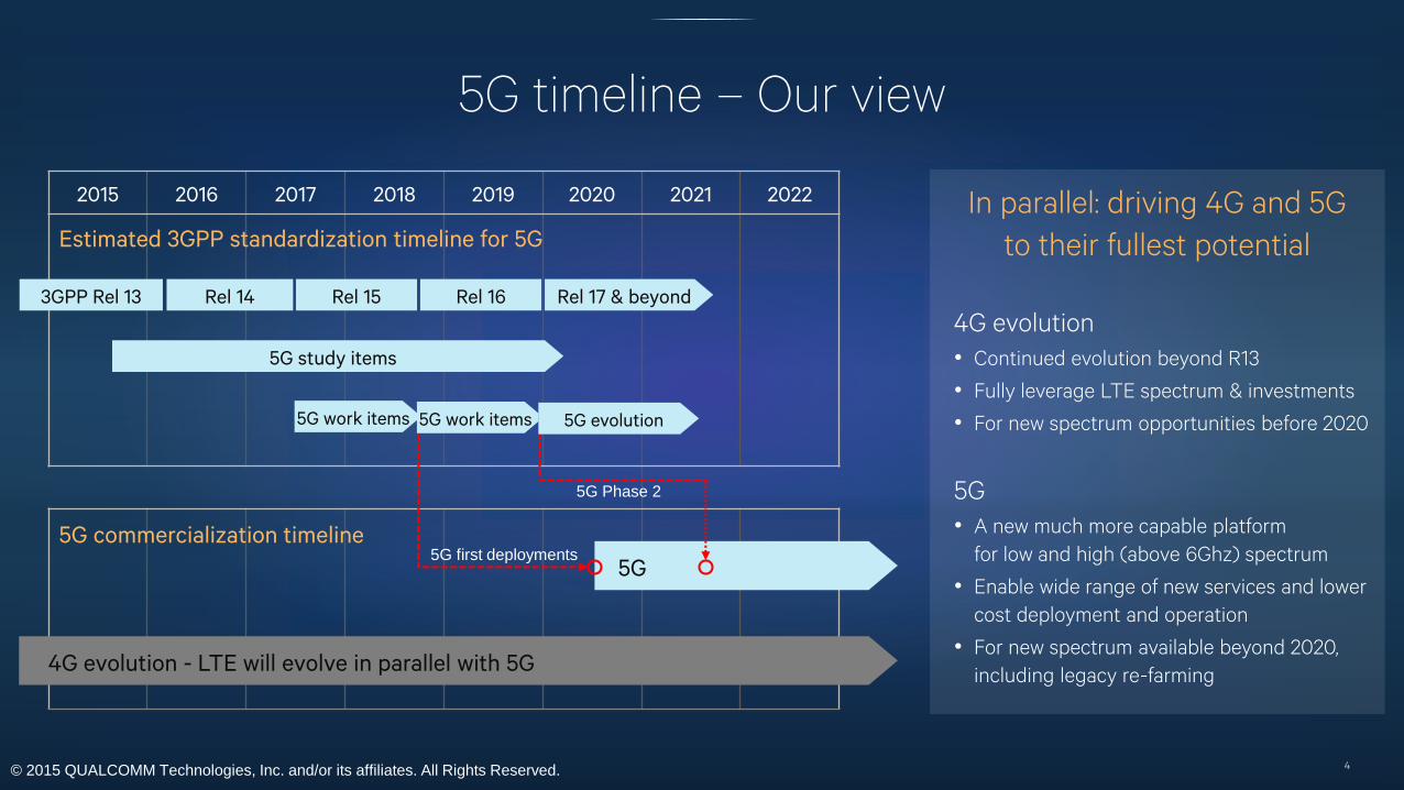
2015 2016 2017 2018 2019 2020 2021 2022
5G timeline – Our view
4
Estimated 3GPP standardization timeline for 5G
4G evolution - LTE will evolve in parallel with 5G
5G
5G study items
5G work items 5G work items
5G commercialization timeline5G first deployments
5G Phase 2
4G evolution
• Continued evolution beyond R13
• Fully leverage LTE spectrum & investments
• For new spectrum opportunities before 2020
5G
• A new much more capable platform
for low and high (above 6Ghz) spectrum
• Enable wide range of new services and lower
cost deployment and operation
• For new spectrum available beyond 2020,
including legacy re-farming
In parallel: driving 4G and 5G
to their fullest potential
Rel 17 & beyond
5G evolution
3GPP Rel 13 Rel 14 Rel 15 Rel 16

© 2015 QUALCOMM Technologies, Inc. and/or its affiliates. All Rights Reserved.
Qualcomm view of the 5G timeline (cont.)
Release 15
a. First phase of 5G: mobile broadband
- licensed & unlicensed (<6GHz, mmWave
under industry consideration)
- FDD & TDD
- wideband (up to ~300 MHz)
- shorter TTI/RTT
- new subframe design
- 4G/5G dual connectivity with LTE anchor
for initial 5G deployments
- forward compatibility hooks
b. 5G study continues in parallel
- mmW, IOE, high reliability, standalone
operation (no LTE anchor)
c. LTE evolution continues in parallel
Release 16
a. Second phase of 5G: all other 5G
components
- 5G mobile broadband
standalone operations
- high reliability
- mmWave
- wide area IOE
b. LTE evolution continues in
parallel
c. Final submission to ITU for IMT-
2020
Release 14
a. 5G requirements study at RAN
level
b. 5G design study item: structure of
air interface to cover multiple areas
- mobile broadband
- internet of everything (IOE)
- high reliability
- high-frequency bands.
c. Parallel study on high-freq channel
models (>6 GHz)
d. LTE evolution to continue in
parallel (parallel sessions in 3GPP
RAN working groups
5
© 2015 QUALCOMM Technologies, Inc. and/or its affiliates. All Rights Reserved. 6
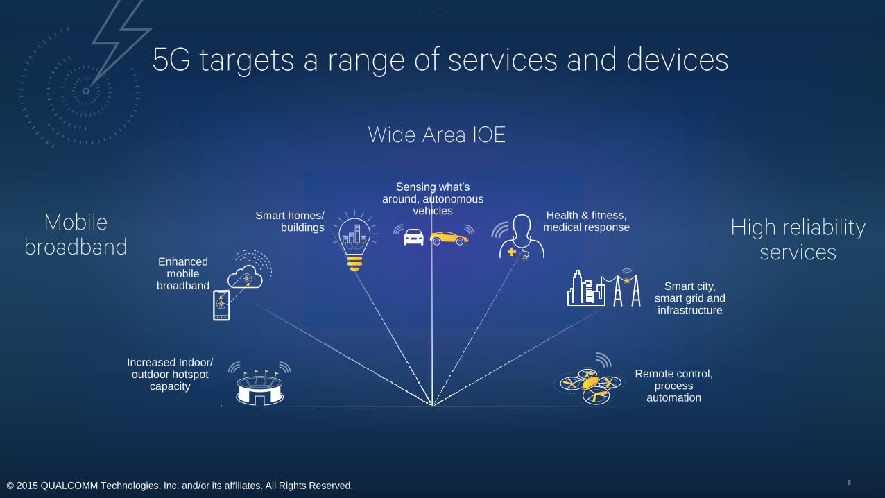
Wide Area IOE
Mobile broadband
High reliability services
Increased Indoor/ outdoor hotspot
capacity
Smart homes/buildings
Health & fitness, medical response
Sensing what’s around, autonomous
vehicles
Remote control, process
automation
5G targets a range of services and devices
Smart city, smart grid and infrastructure
Enhanced mobile
broadband

© 2015 QUALCOMM Technologies, Inc. and/or its affiliates. All Rights Reserved.
Enhanced mobile broadbandImmersive life-like experience for emerging communication, entertainment & other applications
7
Virtual reality• 720Mbps+ for multi-viewing angles
• <50ms e2e latency
Tactile Internet• 1ms e2e latency from action to feedback, e.g.
time from joy-stick action to virtual object
movement and haptic feedback
UHD video streaming• 120Mbps for compressed 8K video at 120fps.
Multi-Gbps for uncompressed 4K/8K videos
3D/UHD telepresence• 100’s of Mbps to multi-Gbps for video calls with
life audiovisual contents depending on quality
requirements
Ultra-fast media download• Multi-Gbps for fast delivery of high quality media,
e.g. downloading a 4K movie at a drive-in kiosk in
seconds
MBB in demanding conditions• Ultra-high user density, e.g. sports venues
• High speed mobility e.g. high-speed trains &
vehicle infotainment
© 2015 QUALCOMM Technologies, Inc. and/or its affiliates. All Rights Reserved.
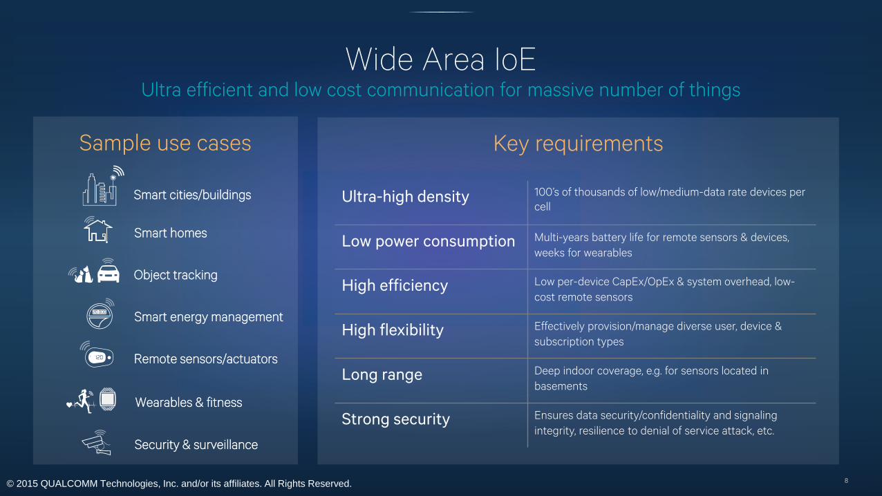
Wide Area IoEUltra efficient and low cost communication for massive number of things
8
Sample use cases
Smart cities/buildings
Smart homes
Object tracking
Smart energy management
Wearables & fitness
Security & surveillance
Ultra-high density 100’s of thousands of low/medium-data rate devices per
cell
Low power consumption Multi-years battery life for remote sensors & devices,
weeks for wearables
High efficiency Low per-device CapEx/OpEx & system overhead, low-
cost remote sensors
High flexibility Effectively provision/manage diverse user, device &
subscription types
Long range Deep indoor coverage, e.g. for sensors located in
basements
Strong security Ensures data security/confidentiality and signaling
integrity, resilience to denial of service attack, etc.
Key requirements
Remote sensors/actuators

© 2015 QUALCOMM Technologies, Inc. and/or its affiliates. All Rights Reserved.
High reliability servicesDelivery of data & control signaling under stringent timing constraints
9
Energy/Smart Grid
• Substation protection & control1
− e2e latency as low as 3ms
− Rate of lost command as low as 1e-8
Industrial Automation
• Process automation2
− e2e latency as low as 5ms
− Packet loss rate as low as 1e-4
• HMI (tactile Internet & augmented reality)2
− e2e latency as low as 1ms
− Data rate up to Gbps range
Automotive
• Cooperative vehicles and other vehicle safety
related functions3
− e2e latency as low as 20ms
Aviation & Robotics
• UAS command & control - e2e latency as low as
50ms4
• Robots for remote handling with haptic feedback:
e2e latency as low as 25ms5
1: IEC61850 and IEC60834. 2. Industry sources. 3. NHTSA, “Vehicle Safety Communications Project Task 3 Final Report”, March 2005. 4. Qualcomm internal research. 5. “Experimental Investigation of Radio Signal Propagation in Scientific
Facilities for Telerobotic Applications” Intech intl’ Journal for Adv. Robotics System. 2013, Vol. 10, 364:2013
© 2015 QUALCOMM Technologies, Inc. and/or its affiliates. All Rights Reserved. 10
5G system design

© 2015 QUALCOMM Technologies, Inc. and/or its affiliates. All Rights Reserved.
Technology enablers for improved system designs
11
Technology
Improved RF/antenna capabilities
Improved radio processing
Improved baseband processing
Virtualized Network Elements
Air Interface Impact
New mmWave bands, and Massive MIMO
with new PHY/MAC design across bands
Faster narrow/wide bandwidth switching
and TDD switching
Lower latency and faster turn around,
new PHY/MAC algorithms
Dynamically move processing between
cloud and edge
• Drive fundamental improvements in user experience, coverage, and cost efficiency
• Deliver high quality of experience and new services across topologies and cell sizes
• New designs below 6 GHz and above 6 GHz including mmWave

© 2015 QUALCOMM Technologies, Inc. and/or its affiliates. All Rights Reserved.
Unified 5G design across spectrum types and bandsFrom narrowband to wideband, licensed & unlicensed, TDD & FDD
12
5G
Range of application requirements
Diverse spectrum typesBand
Single component
carrier channel
Bandwidth examples
Target
Characteristics
FDD/TDD <3 GHz 1, 5, 10, 20MHz
Deep coverage, mobility,
high spectral efficiency,
High reliability, wide area IoE
TDD
≥3GHz
(e.g. 3.8-4.2, 4.4-
4.9)
80, 160MHzOutdoor & indoor, mesh,
Peak rates up to 10gbps
TDD 5GHz 160, 320MHz Unlicensed
TDD mmWave 250, 500 MHz, 1, 2 GHz Indoor & outdoor small cell,
access & backhaul
© 2015 QUALCOMM Technologies, Inc. and/or its affiliates. All Rights Reserved.
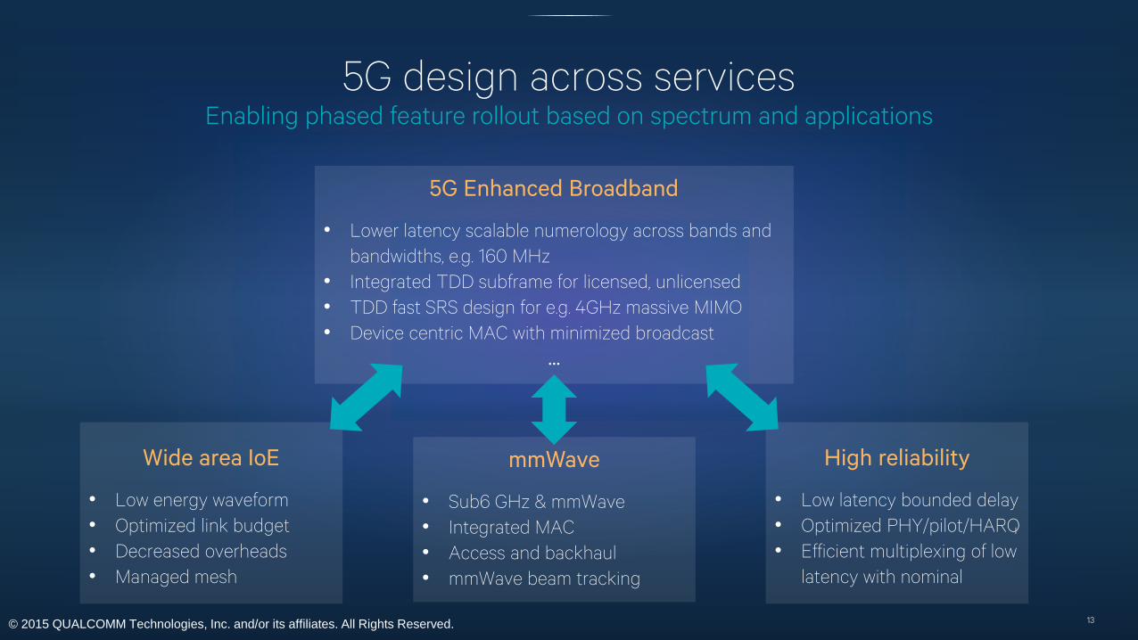
5G design across servicesEnabling phased feature rollout based on spectrum and applications
13
5G Enhanced Broadband
• Lower latency scalable numerology across bands and
bandwidths, e.g. 160 MHz
• Integrated TDD subframe for licensed, unlicensed
• TDD fast SRS design for e.g. 4GHz massive MIMO
• Device centric MAC with minimized broadcast
…
mmWave
• Sub6 GHz & mmWave
• Integrated MAC
• Access and backhaul
• mmWave beam tracking
Wide area IoE
• Low energy waveform
• Optimized link budget
• Decreased overheads
• Managed mesh
High reliability
• Low latency bounded delay
• Optimized PHY/pilot/HARQ
• Efficient multiplexing of low
latency with nominal
© 2015 QUALCOMM Technologies, Inc. and/or its affiliates. All Rights Reserved.
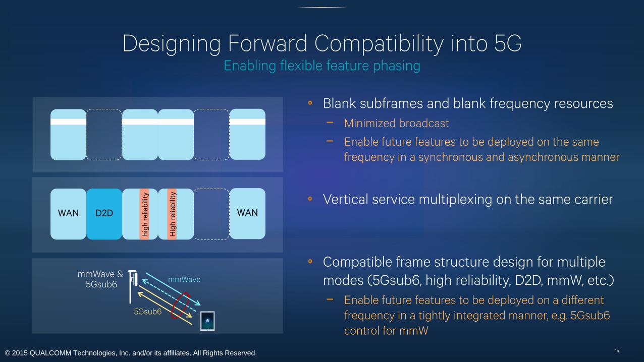
Designing Forward Compatibility into 5GEnabling flexible feature phasing
14
WAN D2D
hig
h r
elia
bilit
y
WAN
Compatible frame structure design for multiple
modes (5Gsub6, high reliability, D2D, mmW, etc.)
− Enable future features to be deployed on a different
frequency in a tightly integrated manner, e.g. 5Gsub6
control for mmW
Vertical service multiplexing on the same carrier
Hig
h r
elia
bilit
y
mmWave & 5Gsub6
5Gsub6
mmWave
Blank subframes and blank frequency resources
− Minimized broadcast
− Enable future features to be deployed on the same
frequency in a synchronous and asynchronous manner
© 2015 QUALCOMM Technologies, Inc. and/or its affiliates. All Rights Reserved.
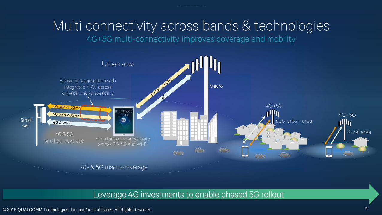
Multi connectivity across bands & technologies4G+5G multi-connectivity improves coverage and mobility
15
Rural area
4G+5G
Sub-urban area4G+5G
Leverage 4G investments to enable phased 5G rollout
4G & 5G
small cell coverage
Macro5G carrier aggregation with
integrated MAC across
sub-6GHz & above 6GHz
Smallcell
multimode device
Simultaneous connectivityacross 5G, 4G and Wi-Fi
Urban area
4G & 5G macro coverage
© 2015 QUALCOMM Technologies, Inc. and/or its affiliates. All Rights Reserved.
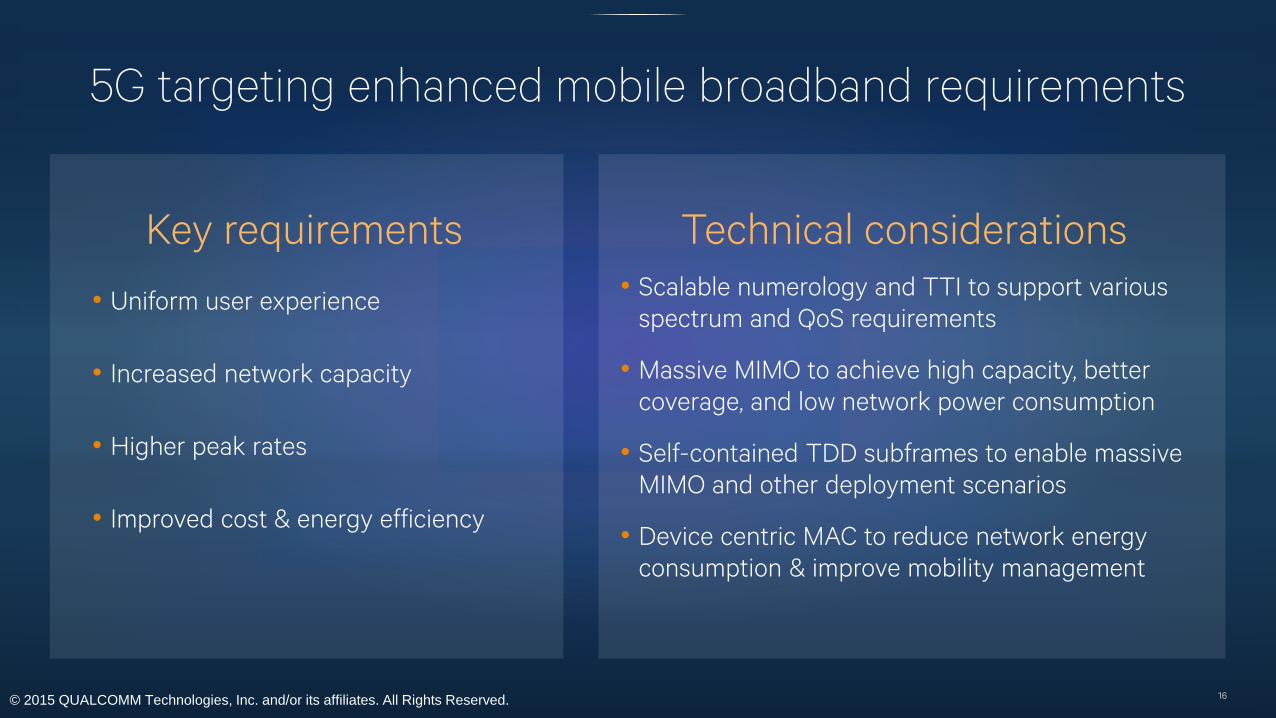
5G targeting enhanced mobile broadband requirements
16
Key requirements
• Uniform user experience
• Increased network capacity
• Higher peak rates
• Improved cost & energy efficiency
Technical considerations
• Scalable numerology and TTI to support various
spectrum and QoS requirements
• Massive MIMO to achieve high capacity, better
coverage, and low network power consumption
• Self-contained TDD subframes to enable massive
MIMO and other deployment scenarios
• Device centric MAC to reduce network energy
consumption & improve mobility management
© 2015 QUALCOMM Technologies, Inc. and/or its affiliates. All Rights Reserved.
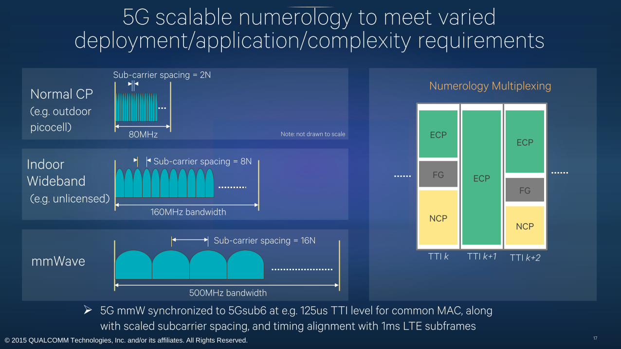
5G scalable numerology to meet varied deployment/application/complexity requirements
17
160MHz bandwidth
Sub-carrier spacing = 8NIndoor
Wideband
(e.g. unlicensed)
Sub-carrier spacing = 2N
80MHz
Normal CP
(e.g. outdoor
picocell)
500MHz bandwidth
Sub-carrier spacing = 16N
mmWave
Note: not drawn to scale ECP
FG
NCP
ECP
ECP
FG
NCP
TTI k TTI k+1 TTI k+2
Numerology Multiplexing
5G mmW synchronized to 5Gsub6 at e.g. 125us TTI level for common MAC, along
with scaled subcarrier spacing, and timing alignment with 1ms LTE subframes
© 2015 QUALCOMM Technologies, Inc. and/or its affiliates. All Rights Reserved.
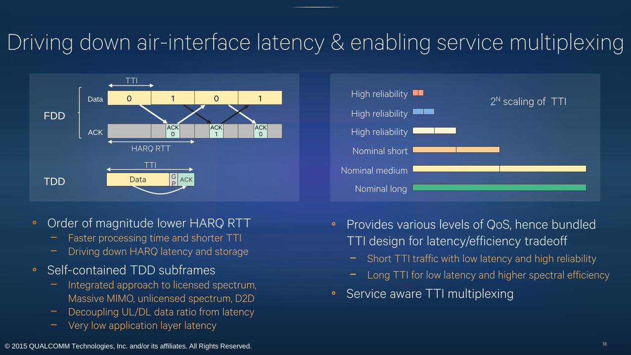
Driving down air-interface latency & enabling service multiplexing
18
Order of magnitude lower HARQ RTT − Faster processing time and shorter TTI
− Driving down HARQ latency and storage
Self-contained TDD subframes− Integrated approach to licensed spectrum,
Massive MIMO, unlicensed spectrum, D2D
− Decoupling UL/DL data ratio from latency
− Very low application layer latency
High reliability
High reliability
High reliability
Nominal short
Nominal medium
Nominal long
2N scaling of TTI
Provides various levels of QoS, hence bundled
TTI design for latency/efficiency tradeoff
− Short TTI traffic with low latency and high reliability
− Long TTI for low latency and higher spectral efficiency
Service aware TTI multiplexing
0 1 0 1
ACK0
Data
ACKACK
1ACK
0
Data GP
ACK
FDD
TDD
HARQ RTT
TTI
TTI
© 2015 QUALCOMM Technologies, Inc. and/or its affiliates. All Rights Reserved.
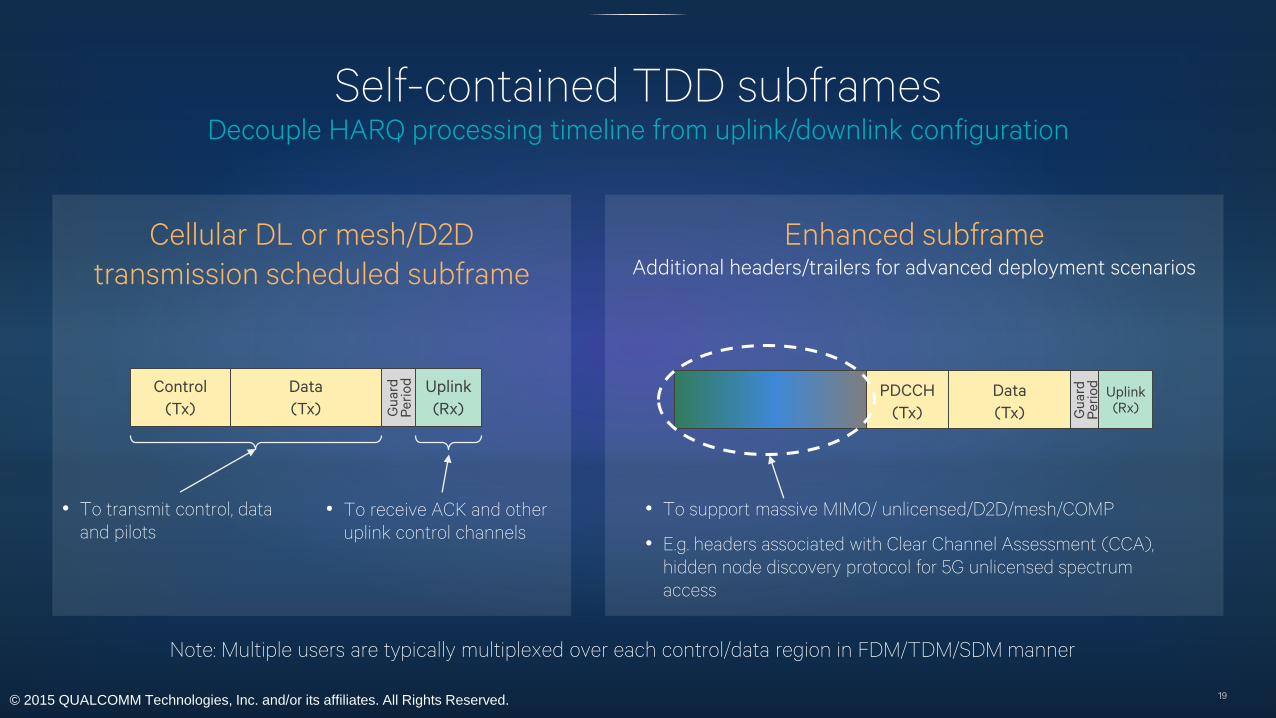
Self-contained TDD subframesDecouple HARQ processing timeline from uplink/downlink configuration
19
Cellular DL or mesh/D2D
transmission scheduled subframe
Control
(Tx)
Data
(Tx) Gu
ard
P
eri
od Uplink
(Rx)
• To transmit control, data
and pilots
• To receive ACK and other
uplink control channels
Enhanced subframeAdditional headers/trailers for advanced deployment scenarios
PDCCH
(Tx)
Data
(Tx) Gu
ard
P
eri
od
Uplink(Rx)
• To support massive MIMO/ unlicensed/D2D/mesh/COMP
• E.g. headers associated with Clear Channel Assessment (CCA),
hidden node discovery protocol for 5G unlicensed spectrum
access
Note: Multiple users are typically multiplexed over each control/data region in FDM/TDM/SDM manner
© 2015 QUALCOMM Technologies, Inc. and/or its affiliates. All Rights Reserved.
5G modulation and access techniques
20
OFDM for enhanced mobile broadband access
− 5G broadband access requires the following
− Low latency
− Wide channel bandwidth and high data rate
− Low complexity per bit
− OFDM is well suited to meet these requirements due to the following characteristics
− Scalable symbol duration and subcarrier spacing
− Low complexity receiver for wide bandwidth
− Efficiently supports MIMO spatial multiplexing and multiuser SDMA
− OFDM implementations allow for additional transmit/receiver filtering based on link and adjacent
channel requirements
In addition, resource spread multiple access (RSMA) waveforms have advantages for
uplink short data bursts such as low power IoE− Supports asynchronous, non-orthogonal, contention based access
− Reduces IoE device power overhead
© 2015 QUALCOMM Technologies, Inc. and/or its affiliates. All Rights Reserved.
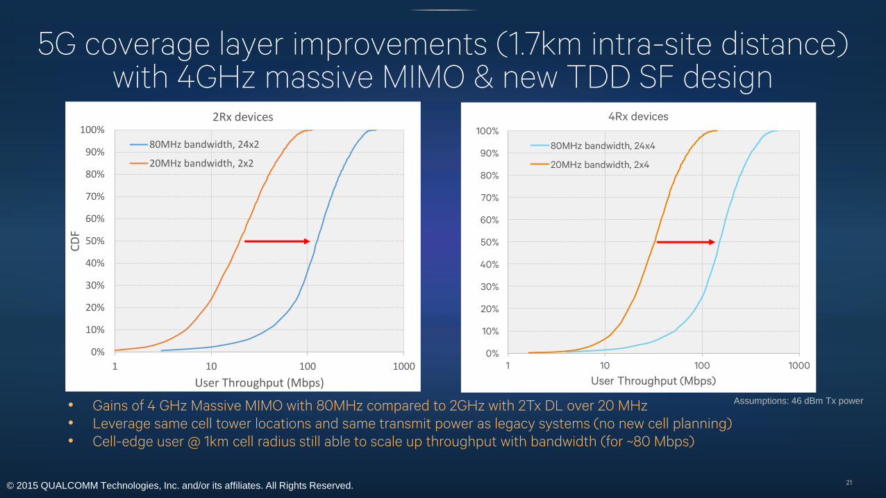
5G coverage layer improvements (1.7km intra-site distance)with 4GHz massive MIMO & new TDD SF design
21
• Gains of 4 GHz Massive MIMO with 80MHz compared to 2GHz with 2Tx DL over 20 MHz
• Leverage same cell tower locations and same transmit power as legacy systems (no new cell planning)
• Cell-edge user @ 1km cell radius still able to scale up throughput with bandwidth (for ~80 Mbps)
0%
10%
20%
30%
40%
50%
60%
70%
80%
90%
100%
1 10 100 1000
CD
F
User Throughput (Mbps)
2Rx devices
80MHz bandwidth, 24x2
20MHz bandwidth, 2x2
0%
10%
20%
30%
40%
50%
60%
70%
80%
90%
100%
1 10 100 1000
User Throughput (Mbps)
4Rx devices
80MHz bandwidth, 24x4
20MHz bandwidth, 2x4
Assumptions: 46 dBm Tx power
© 2015 QUALCOMM Technologies, Inc. and/or its affiliates. All Rights Reserved.
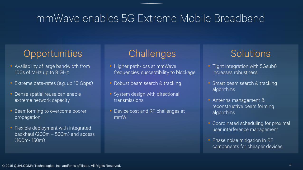
mmWave enables 5G Extreme Mobile Broadband
22
Challenges• Higher path-loss at mmWave
frequencies, susceptibility to blockage
• Robust beam search & tracking
• System design with directional
transmissions
• Device cost and RF challenges at
mmW
Opportunities• Availability of large bandwidth from
100s of MHz up to 9 GHz
• Extreme data-rates (e.g. up 10 Gbps)
• Dense spatial reuse can enable
extreme network capacity
• Beamforming to overcome poorer
propagation
• Flexible deployment with integrated
backhaul (200m – 500m) and access
(100m- 150m)
Solutions • Tight integration with 5Gsub6
increases robustness
• Smart beam search & tracking
algorithms
• Antenna management &
reconstructive beam forming
algorithms
• Coordinated scheduling for proximal
user interference management
• Phase noise mitigation in RF
components for cheaper devices

© 2015 QUALCOMM Technologies, Inc. and/or its affiliates. All Rights Reserved.
mmW deployment scenarios
Stand alone mmW access Collocated mmW + 5Gsub6 access
mmW integrated access & backhaul relayNon-collocated mmW + 5Gsub6 access
5Gsub6 mmW23

© 2015 QUALCOMM Technologies, Inc. and/or its affiliates. All Rights Reserved.
Millimeter Wave: Opportunities and ChallengesMassive bandwidths and spatial reuse counter-balanced by robustness and device aspects
24
Availability of large bandwidths
Dense spatial reuse
Beamforming advantage
Coverage through reflections and LoS
Characteristics
Robust beam search & tracking
Device and RF challenges at MMW
Effective fallback to low frequency
System design with directional
transmissions
Key System Challenges
Example: Outdoor Deployment
MWB – ~100-200 m cell sizeIntegrated
Backhaul
UE-relay
Mobile
mmwB or UE
LOS
NLOS
Indoor distribution
© 2015 QUALCOMM Technologies, Inc. and/or its affiliates. All Rights Reserved.
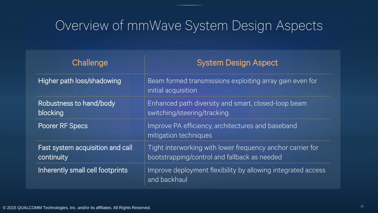
Overview of mmWave System Design Aspects
25
Challenge System Design Aspect
Higher path loss/shadowing Beam formed transmissions exploiting array gain even for
initial acquisition
Robustness to hand/body
blocking
Enhanced path diversity and smart, closed-loop beam
switching/steering/tracking
Poorer RF Specs Improve PA efficiency, architectures and baseband
mitigation techniques
Fast system acquisition and call
continuity
Tight interworking with lower frequency anchor carrier for
bootstrapping/control and fallback as needed
Inherently small cell footprints Improve deployment flexibility by allowing integrated access
and backhaul

© 2015 QUALCOMM Technologies, Inc. and/or its affiliates. All Rights Reserved.
Penetration Loss: An ExampleOut-to-in penetration loss for a tinted external window
26
• Out-to-in penetration loss can be challenging
• Suburban areas impacted heavily by foliage
• Windows with metallic tint tend to reflect rather than allow signal to pass through
• Insulation wrapped in metal foil can also cause reflections and reduce penetrability
© 2015 QUALCOMM Technologies, Inc. and/or its affiliates. All Rights Reserved.
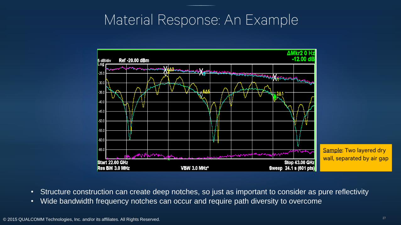
Material Response: An Example
27
Sample: Two layered dry
wall, separated by air gap
• Structure construction can create deep notches, so just as important to consider as pure reflectivity
• Wide bandwidth frequency notches can occur and require path diversity to overcome
© 2015 QUALCOMM Technologies, Inc. and/or its affiliates. All Rights Reserved.
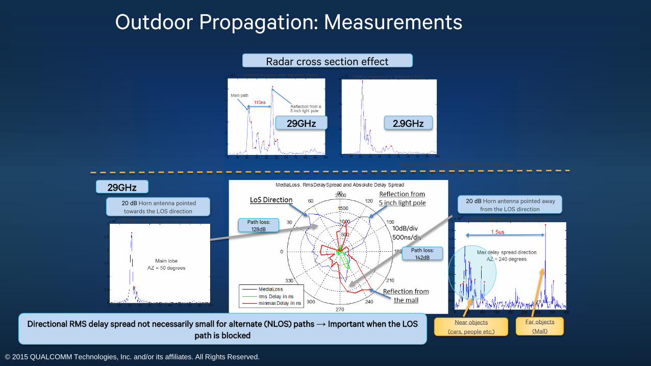
Outdoor Propagation: Measurements
Radar cross section effect
29GHz 2.9GHz
10dB/div
500ns/div
Directional RMS delay spread not necessarily small for alternate (NLOS) paths → Important when the LOS
path is blocked
Response of omnidirectional antennas
20 dB Horn antenna pointed
towards the LOS direction
20 dB Horn antenna pointed away
from the LOS direction
Near objects
(cars, people etc.)
Far objects
(Mall)
29GHz
Path loss:
128dB
Path loss:
142dB
© 2015 QUALCOMM Technologies, Inc. and/or its affiliates. All Rights Reserved.
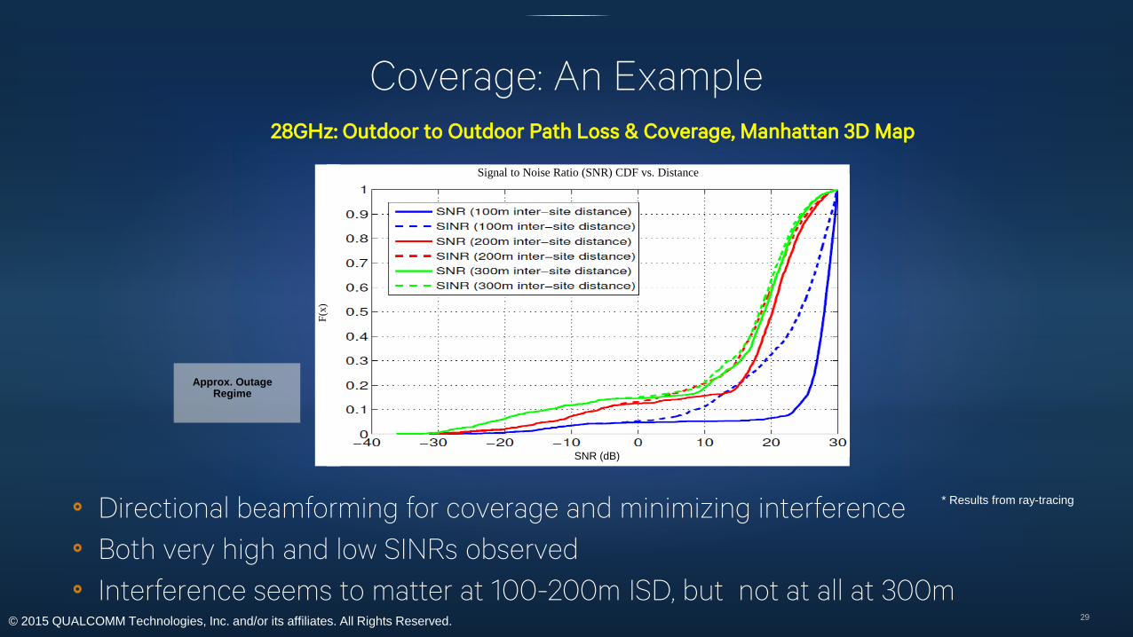
Signal to Noise Ratio (SNR) CDF vs. Distance
SNR (dB)
F(x
)
Coverage: An Example
29
Directional beamforming for coverage and minimizing interference
Both very high and low SINRs observed
Interference seems to matter at 100-200m ISD, but not at all at 300m
28GHz: Outdoor to Outdoor Path Loss & Coverage, Manhattan 3D Map
Approx. Outage Regime
* Results from ray-tracing
© 2015 QUALCOMM Technologies, Inc. and/or its affiliates. All Rights Reserved.
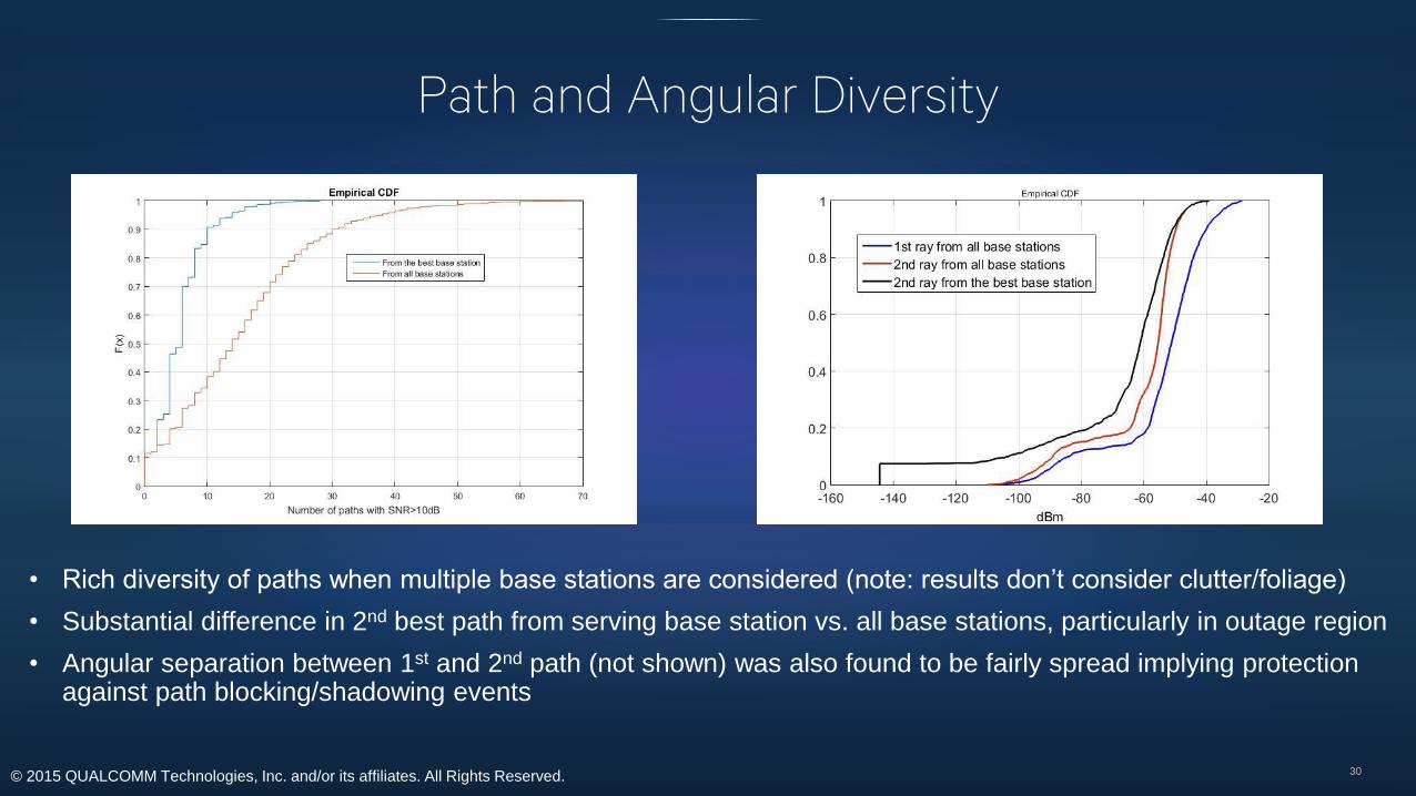
Path and Angular Diversity
30
• Rich diversity of paths when multiple base stations are considered (note: results don’t consider clutter/foliage)
• Substantial difference in 2nd best path from serving base station vs. all base stations, particularly in outage region
• Angular separation between 1st and 2nd path (not shown) was also found to be fairly spread implying protection against path blocking/shadowing events
© 2015 QUALCOMM Technologies, Inc. and/or its affiliates. All Rights Reserved.
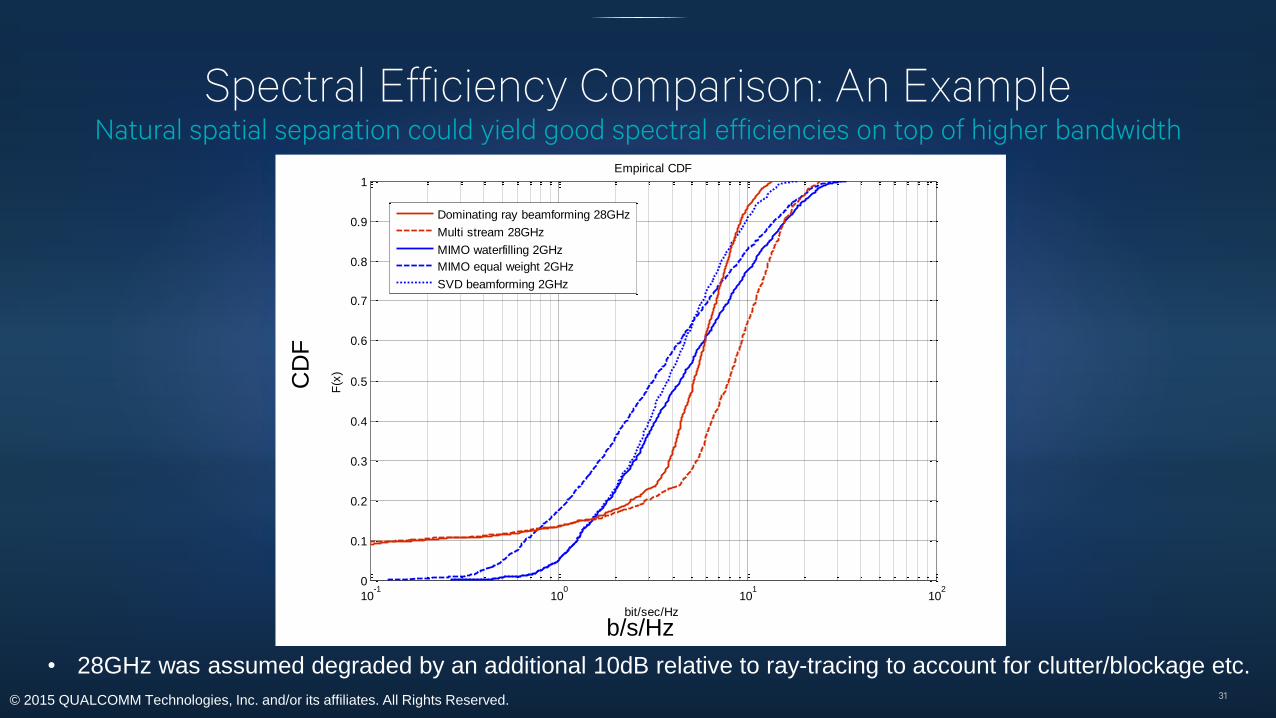
Spectral Efficiency Comparison: An ExampleNatural spatial separation could yield good spectral efficiencies on top of higher bandwidth
31
10-1
100
101
102
0
0.1
0.2
0.3
0.4
0.5
0.6
0.7
0.8
0.9
1
bit/sec/Hz
F(x
)
Empirical CDF
Dominating ray beamforming 28GHz
Multi stream 28GHz
MIMO waterfilling 2GHz
MIMO equal weight 2GHz
SVD beamforming 2GHz
b/s/Hz
CD
F
• 28GHz was assumed degraded by an additional 10dB relative to ray-tracing to account for clutter/blockage etc.
© 2015 QUALCOMM Technologies, Inc. and/or its affiliates. All Rights Reserved.
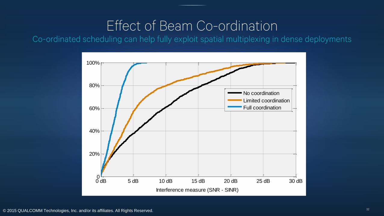
Effect of Beam Co-ordinationCo-ordinated scheduling can help fully exploit spatial multiplexing in dense deployments
32
0 dB 5 dB 10 dB 15 dB 20 dB 25 dB 30 dB0
20%
40%
60%
80%
100%
Interference measure (SNR - SINR)
No coordination
Limited coordination
Full coordination
© 2015 QUALCOMM Technologies, Inc. and/or its affiliates. All Rights Reserved.
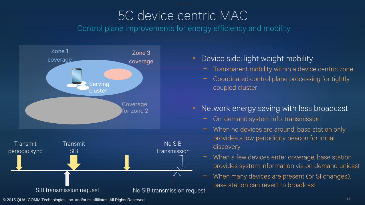
5G device centric MACControl plane improvements for energy efficiency and mobility
33
Zone 1
coverage
Coverage for zone 2
Serving cluster
Device side: light weight mobility
− Transparent mobility within a device centric zone
− Coordinated control plane processing for tightly
coupled cluster
Network energy saving with less broadcast
− On-demand system info. transmission
− When no devices are around, base station only
provides a low periodicity beacon for initial
discovery
− When a few devices enter coverage, base station
provides system information via on demand unicast
− When many devices are present (or SI changes),
base station can revert to broadcast
Zone 3
coverage
Transmit
periodic sync
Transmit
SIB
No SIB
Transmission
SIB transmission request No SIB transmission request

© 2015 QUALCOMM Technologies, Inc. and/or its affiliates. All Rights Reserved.
5G targeting high reliability service requirements
34
Key requirements
• High reliability and availability
• Low end-to-end latency
• Minimal impacts to nominal traffic while
meeting reliability and latency
requirements
Technical considerations
• Integrated nominal/high-reliability system design
- New PHY coding, New FEC, and link-adaptation framework
for efficient traffic multiplexing
• Low latency design
- Efficient HARQ structure for fast turn-around
- Scalable TTI for latency, reliability & efficiency tradeoff
• High reliability design
- Large diversity orders to support bursty high-reliability traffic
- New link adaptation paradigm for lower error rates

© 2015 QUALCOMM Technologies, Inc. and/or its affiliates. All Rights Reserved.
Hard latency bound and PHY/MAC design
35
2nd tx queue
1st tx queue
Residual RTT
Poisson arrivals
3rd tx queue
nth tx queue
time
freq.
...
1st Tx HARQ
2nd Tx HARQ
3rd Tx HARQ
nth Tx HARQ
Packet drop at Rx
Successful
transmission
Failed transmission
Failed 1st Tx
Failed 2nd Tx
Failed (n-1)th Tx
...
Highest
priority
Lowest
priorityPa
ck
et lo
ss a
t Tx
• Causes of packet drop1. Last transmission fails at Rx2. Delay exceeds deadline at Tx queues
Single-cell multi-user evaluation/queueing model
© 2015 QUALCOMM Technologies, Inc. and/or its affiliates. All Rights Reserved.
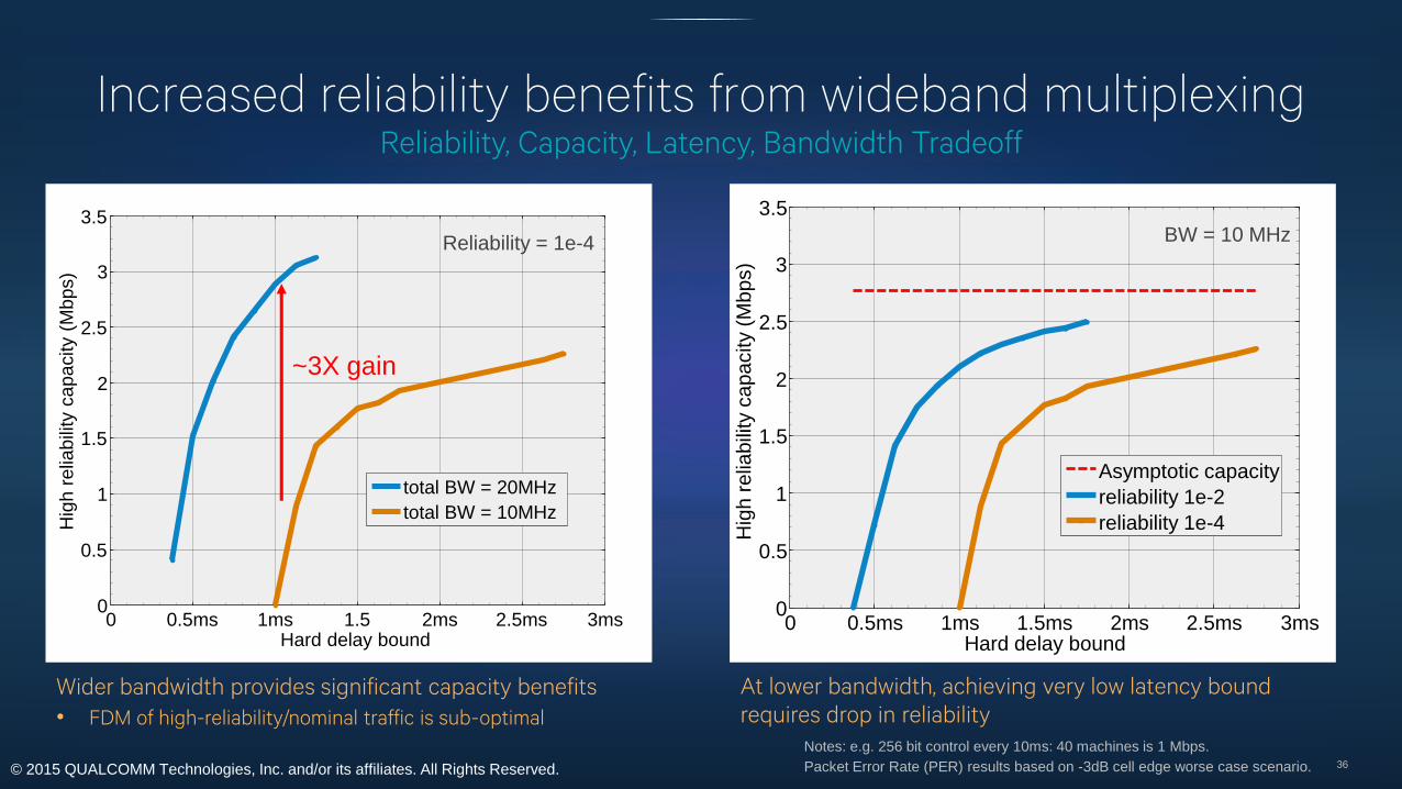
Increased reliability benefits from wideband multiplexing
36
Wider bandwidth provides significant capacity benefits
• FDM of high-reliability/nominal traffic is sub-optimal
At lower bandwidth, achieving very low latency bound
requires drop in reliability
Notes: e.g. 256 bit control every 10ms: 40 machines is 1 Mbps.
Packet Error Rate (PER) results based on -3dB cell edge worse case scenario.
Reliability = 1e-4
Reliability, Capacity, Latency, Bandwidth Tradeoff
0 0.5ms 1ms 1.5 2ms 2.5ms 3ms0
0.5
1
1.5
2
2.5
3
3.5
Hard delay bound
Hig
h r
elia
bili
ty c
apacity (
Mbps)
total BW = 20MHz
total BW = 10MHz
~3X gain
0 0.5ms 1ms 1.5ms 2ms 2.5ms 3ms0
0.5
1
1.5
2
2.5
3
3.5
Hard delay bound
Hig
h r
elia
bili
ty c
apacity (
Mbps)
Asymptotic capacity
reliability 1e-2
reliability 1e-4
BW = 10 MHzReliability = 1e-4

© 2015 QUALCOMM Technologies, Inc. and/or its affiliates. All Rights Reserved.
5G targeting wide area IOE requirements
37
Key requirements
• Superior coverage for supporting
remote and deep indoor nodes
• Low power consumption to
enable longer battery life
• Better support low rate bursty
communications from multiple
device types including
smartphone bursty traffic
• Scalability to enable massive
number of connections
Technical Approaches
IOE
IOE
IOEIOE
IOE
Direct access on
licensed e.g. FDD
Mesh on unlicensed or
partitioned with uplink FDD
Uplink IOE
Non-Orthogonal
Distributed Scheduling
Downlink IOE
Orthogonal
Centralized Scheduling
Non-orthogonal RSMA
• Resource spread multiple
access
• Avoids energy cost of
establishing synchronism
• Distributed scheduling
Uplink mesh downlink direct
• Leverage DL sync
• Coverage extension

© 2015 QUALCOMM Technologies, Inc. and/or its affiliates. All Rights Reserved. 38
Perspectives on
5G system architecture
© 2015 QUALCOMM Technologies, Inc. and/or its affiliates. All Rights Reserved.
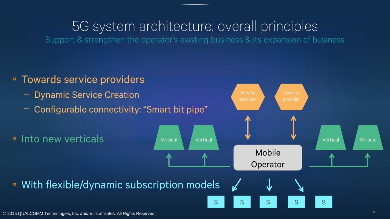
5G system architecture: overall principlesSupport & strengthen the operator’s existing business & its expansion of business
39
Towards service providers
− Dynamic Service Creation
− Configurable connectivity: “Smart bit pipe”
Into new verticals
With flexible/dynamic subscription models
Mobile
Operator
VerticalVertical Vertical Vertical
Service
provider
Service
provider
S S S S S

© 2015 QUALCOMM Technologies, Inc. and/or its affiliates. All Rights Reserved.
Expansion towards new service providers
40
Enable operators to enhance value of connectivity towards OTT providers
Characteristics of required connectivity (and additional features on top of it)
may change depending on the specific service provider
The operator’s 5G mobile network should be a “toolbox” that can be
monetized adequately towards those service providers
Goal: Design 5G architecture such that it provides corresponding tools
− Dynamic service creation
− Configurable connectivity – “Smart bit pipe”

© 2015 QUALCOMM Technologies, Inc. and/or its affiliates. All Rights Reserved.
Expansion into new verticals
41
Verticals in EPC
− Require changes to existing architecture mechanisms for the
support of the new class of devices
− Introduced as gradual enhancements
− E.g., single MME function becoming more complex over time
New verticals proposed for 5G & more expected to come
Goal: Introduce ability to support new verticals
− With minimal impact on existing devices
− Without being burdened by other verticals
Rel-10
Rel-9
Rel-8
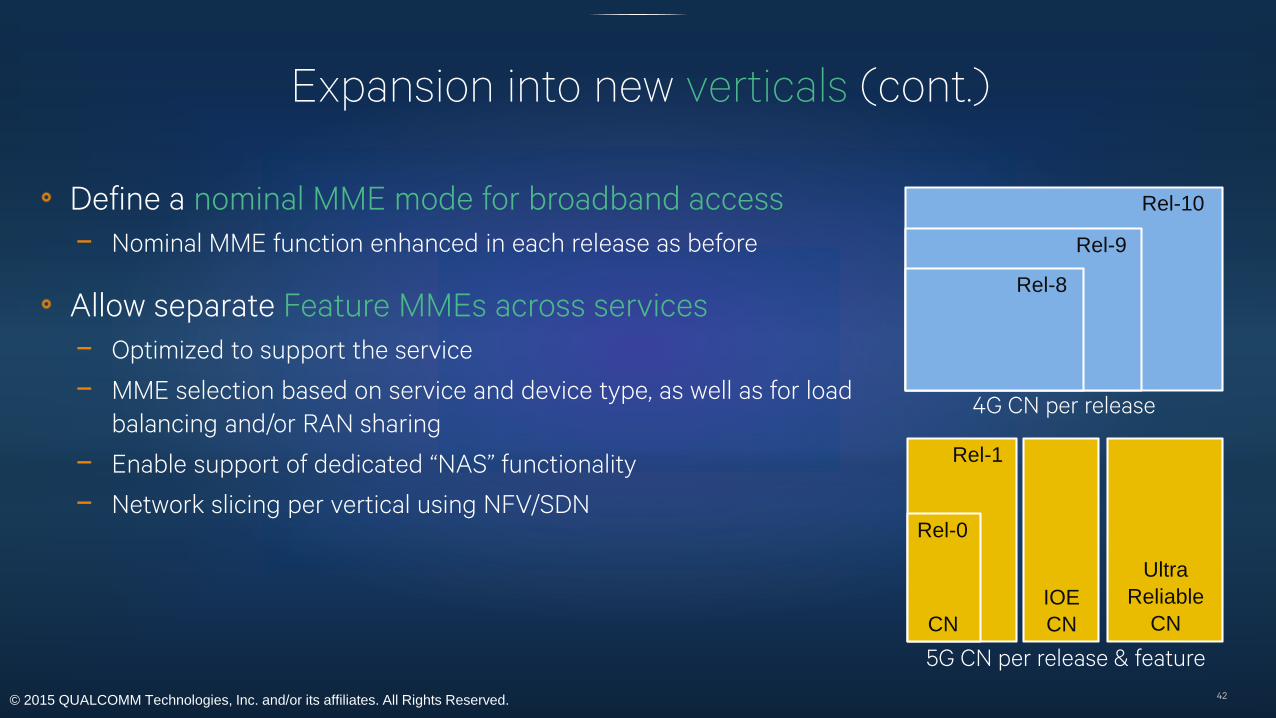
4G CN per release
© 2015 QUALCOMM Technologies, Inc. and/or its affiliates. All Rights Reserved.
Expansion into new verticals (cont.)
42
Define a nominal MME mode for broadband access
− Nominal MME function enhanced in each release as before
Allow separate Feature MMEs across services
− Optimized to support the service
− MME selection based on service and device type, as well as for load
balancing and/or RAN sharing
− Enable support of dedicated “NAS” functionality
− Network slicing per vertical using NFV/SDN
Rel-10
Rel-9
Rel-8
4G CN per release
Rel-0
Rel-1
CN
IOE
CN
Ultra
Reliable
CN
5G CN per release & feature

© 2015 QUALCOMM Technologies, Inc. and/or its affiliates. All Rights Reserved.
Support more diverse connectivity management models
43
Current limitations
− Single connectivity context between user device & connectivity management in the network
− Unless dedicated hardware is present for multiple connectivity via multiple SIM cards
− Tight connection between the use of the access link & the connectivity context
− Subscriber is closely tied to the device
Goals:
− Separate concept of radio connectivity subscription from service subscription
− Enable devices with multiple “personalities” to simultaneously connect to multiple core
networks as needed
− Multiple subscriptions simultaneously active on a device over a single physical connection
− One subscription possibly being active over multiple devices simultaneously
© 2015 QUALCOMM Technologies, Inc. and/or its affiliates. All Rights Reserved.
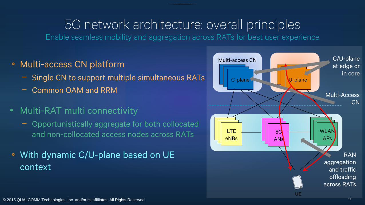
5G network architecture: overall principlesEnable seamless mobility and aggregation across RATs for best user experience
44
Multi-access CN platform
− Single CN to support multiple simultaneous RATs
− Common OAM and RRM
• Multi-RAT multi connectivity
− Opportunistically aggregate for both collocated
and non-collocated access nodes across RATs
With dynamic C/U-plane based on UE
context
LTE
eNBs
5G
ANs
WLAN
APs
Multi-access CN
C-plane
RAN
aggregation
and traffic
offloading
across RATs
U-plane
C/U-plane
at edge or
in core
Multi-Access
CN
UE

© 2015 QUALCOMM Technologies, Inc. and/or its affiliates. All Rights Reserved.
Dynamic C/U-plane – legacy centralized network topology
45
3G/4G introduced traffic offload to the edge in Rel-10
But the C-plane still resides in the CN
− Impacts latency and still requires a significant signaling load
especially for small data
Most devices and data connections are for stationary
users
− Ideally the 5G would move the C/U-plane to the edge for
devices that are stationary or have only nomadic service
− While enabling processing deeper in the network and
mobility when devices are mobile
PGW
eNodeB
HSS
RRC PDCP/RLC
MME SGW
PGW
eNodeB
HSS
RRC PDCP/RLC
MME
SGW
Controlplane
Userplane
Controlplane
Userplane
LTE(Rel-8)
LTE-Advanced(Rel-10)
© 2015 QUALCOMM Technologies, Inc. and/or its affiliates. All Rights Reserved.
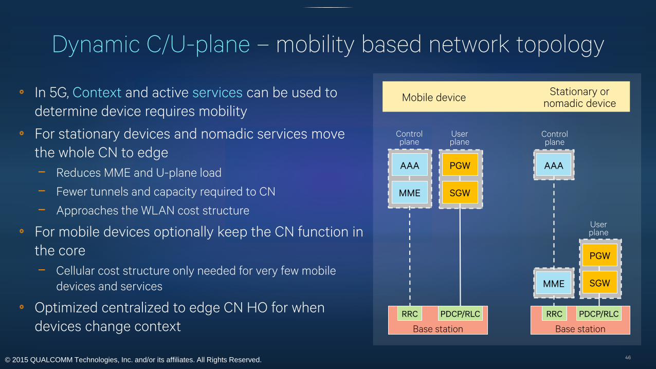
In 5G, Context and active services can be used to
determine device requires mobility
For stationary devices and nomadic services move
the whole CN to edge
− Reduces MME and U-plane load
− Fewer tunnels and capacity required to CN
− Approaches the WLAN cost structure
For mobile devices optionally keep the CN function in
the core
− Cellular cost structure only needed for very few mobile
devices and services
Optimized centralized to edge CN HO for when
devices change context
Dynamic C/U-plane – mobility based network topology
46
PGW
Base station
AAA
RRC PDCP/RLC
MME SGW
PGW
Base station
AAA
RRC PDCP/RLC
MME SGW
Controlplane
Userplane
Controlplane
Userplane
Mobile deviceStationary or
nomadic device
© 2015 QUALCOMM Technologies, Inc. and/or its affiliates. All Rights Reserved.
For more information on Qualcomm, visit us at:
www.qualcomm.com & www.qualcomm.com/blog
Qualcomm is a trademark of Qualcomm Incorporated, registered in the United States and other countries,
used with permission. Other products or brand names may be trademarks or registered trademarks of their respective owners.
References in this presentation to “Qualcomm” may mean Qualcomm Incorporated, Qualcomm Technologies, Inc., and/or other subsidiaries or business units within the
Qualcomm corporate structure, as applicable. Qualcomm Incorporated includes Qualcomm’s licensing business, QTL, and the vast majority of its patent portfolio.
Qualcomm Technologies, Inc., a wholly-owned subsidiary of Qualcomm Incorporated, operates, along with its subsidiaries, substantially all of Qualcomm’s engineering,
research and development functions, and substantially all of its product and services businesses, including its semiconductor business, QCT.
Thank youFollow us on:
47