joining & field procedures for pipe pe3608/pe3408 pe4710
TRANSCRIPT

Joining & Field Procedures For Pipe
PE3608/PE3408 PE4710/PE3408 PE2606/PE2406 PE2708/PE2406
WL101

2 Joining & Field Procedures for Pipe
WL101-0606 Rev Jun 2006 Supersedes all previous editions © 2006 WL Plastics Corp.
NOTICE
This publication is intended for use as a guide for piping systems. It should not be used in place of a professional engineer’s judgment or advice and it is not intended as installation instructions. WL Plastics Corporation has made every reasonable effort to ensure accuracy, but the information in this publication may not be complete, especially for special or unusual applications. The information in this publication cannot be guaranteed because the conditions of use are beyond our control and the information in this publication does not constitute a guarantee or warranty for piping installations. The user of this information assumes all risk associated with its use. Changes to this publication may occur from time to time without notice. Contact WL Plastics Corporation to determine if you have the most current edition.

Joining & Field Procedures for Pipe 3
WL101-0606 Rev Jun 2006 Supersedes all previous editions © 2006 WL Plastics Corp.
Table of Contents Pipe Unloading and Handling.................................................................................................................................................. 5
Unloading Guidelines .......................................................................................................................................................... 5 Jobsite Pipe Storage, Unpacking, and Handling................................................................................................................. 5 Pipe Weight ......................................................................................................................................................................... 6 Subfreezing and Inclement Weather Conditions................................................................................................................. 6 Field Bending....................................................................................................................................................................... 6
Hazardous Environments........................................................................................................................................................ 6 Static Electric Discharge...................................................................................................................................................... 6 Underground Excavation ..................................................................................................................................................... 7 Confined Spaces ................................................................................................................................................................. 7
Fusion and Joining .................................................................................................................................................................. 7 Liquid Hydrocarbon Permeated Pipe .................................................................................................................................. 8 Butt Fusion........................................................................................................................................................................... 8
Butt Fusion Procedure ..................................................................................................................................................... 9 Secure the Components in the Butt Fusion Equipment................................................................................................... 9 Face the Component Ends .............................................................................................................................................. 9 Align the Faced Component Ends ................................................................................................................................. 10 Melt the Component Ends ............................................................................................................................................. 10 Join, Apply and Hold Fusion Joining Force, Cooling ..................................................................................................... 11 Visually Inspect Fusion Bead Appearance .................................................................................................................... 12 Approximate Butt Fusion Joining Rates......................................................................................................................... 12 Bead Removal ............................................................................................................................................................... 13
Saddle (Sidewall) Fusion................................................................................................................................................... 13 Required Equipment ...................................................................................................................................................... 14 Optional Equipment ....................................................................................................................................................... 14 Saddle Fusion Terms..................................................................................................................................................... 14 Heating Tool Temperature ............................................................................................................................................. 15 Saddle Fusion Procedure .............................................................................................................................................. 15 Preparation .................................................................................................................................................................... 16 Heating........................................................................................................................................................................... 16 Fusion and Cooling ........................................................................................................................................................ 16 Visually Inspect Fusion Bead Appearance .................................................................................................................... 17
Socket Fusion and Electrofusion....................................................................................................................................... 17 Fusion Training and Proficiency ........................................................................................................................................ 18 Data Logging ..................................................................................................................................................................... 19 Electrofusion...................................................................................................................................................................... 19 Extrusion and Hot-Air (Hot-Gas) Welding ......................................................................................................................... 19 Tapered Pipe Threads....................................................................................................................................................... 19

4 Joining & Field Procedures for Pipe
WL101-0606 Rev Jun 2006 Supersedes all previous editions © 2006 WL Plastics Corp.
Mechanical Connections ................................................................................................................................................... 19 Testing................................................................................................................................................................................... 20
Field Leak Testing ............................................................................................................................................................. 20 Pneumatic Tests................................................................................................................................................................ 21 Field Pressure Testing....................................................................................................................................................... 21
Installation ............................................................................................................................................................................. 21 Repair.................................................................................................................................................................................... 21 Operating Procedures ........................................................................................................................................................... 22
Disinfecting Potable Water Piping ..................................................................................................................................... 22 Squeeze-Off ...................................................................................................................................................................... 22 Cleaning............................................................................................................................................................................. 22
References............................................................................................................................................................................ 23

Joining & Field Procedures for Pipe 5
WL101-0606 Rev Jun 2006 Supersedes all previous editions © 2006 WL Plastics Corp.
PIPE UNLOADING AND HANDLING Unloading Guidelines The truck driver receives WL Plastics Unloading Guidelines, publication WL111, when accepting the load at the manufacturing plant. The driver is instructed to give WL Plastics Unloading Guidelines to unloading personnel at the unloading site.
Before unloading WL Plastics pipe from the truck, unloading personnel should obtain WL Plastics Unloading Guidelines from the driver and read the WL Plastics Unloading Guidelines.
WARNING – Observe WL Plastics Unloading Guidelines whenever unloading WL Plastics pipe products. Improper unloading can result in death, injury, property damage or product damage. Jobsite Pipe Storage, Unpacking, and Handling The jobsite pipe storage area should be relatively level and smooth, and large enough for the safe movement of pipe and handling equipment. In general, pipe should be stored as packaged until it is needed for installation.
On level ground, do not stack bulk packs higher than they were stacked on the truck. On less level ground, bulk packs should not be stacked, but should be stored individually on the ground.
Bulk packs must be on the ground before banding is removed.
Coiled pipe should be stored as packaged on relatively level, smooth ground. Do not stack coils higher than the original packaging. Individual coils are lifted with appropriate lifting equipment, which is typically by extending padded forklift forks into the center of the coil, or by lifting the coil with fabric slings – not chain or wire rope – looped through the center of the coil. Forks can be padded by installing fork-length sections of plastic pipe over the forks.
Coils that are packaged on pallets should be removed one by one from the top down. Remove only enough banding to release the upper coil, and then slide the coil over onto forklift forks. Forks must be long enough for the full coil diameter, and set apart as wide as practical. Do not push coils off the silo onto the ground.
Take safety measures to protect persons against injury before banding on individual coils is removed, – coiled pipe will spring out suddenly with force when restraining bands are removed. Safety measures can include placing the coil in equipment that confines the coil, cutting bands from inside of the coil, or other safety measures. When coils are placed in confining equipment, never place any part of the body – hands, arms, feet legs, head – between the coil and the confining equipment.
Observe WL Plastics Unloading Guidelines (WL111) with WL Plastics pipe products:
• Keep persons who are not involved in handling WL Plastics piping products away from handling operations.
• When piping products and handling equipment are in motion, all persons involved in handling WL Plastics piping products should be able to see each other at all times. If any handling person is not in sight, immediately stop moving equipment and products and locate that person. Do not continue until all persons are accounted for and in sight.
• Use only appropriate lifting and handling equipment that is in safe operating condition, that is properly rated for the load, and that is designed for the intended use.
• Do not lift or move WL Plastics products with equipment such as wire rope or chain that can damage the pipe. Equipment that contacts the pipe should be fabric slings or should be rounded or padded to prevent damage to the pipe.
• Uncontrolled movement of products or equipment can be hazardous. Never push, roll, dump or drop pipe lengths, bundles or coils off the truck, off handling equipment or into a trench. Always use appropriate equipment to lift, move and lower the pipe.

6 Joining & Field Procedures for Pipe
WL101-0606 Rev Jun 2006 Supersedes all previous editions © 2006 WL Plastics Corp.
Pipe Weight Polyethylene pipe is lightweight compared to other piping products, but larger pipe sizes, longer lengths, and large coils of pipe can be heavy. WL Plastics publishes weight information for polyethylene piping products. See WL102A and WL102B for weight per foot for IPS sized pipe, WL104A and WL104B for weight per foot for DIPS sized pipe, and WL108 for standard packaging and truckload quantities for coiled pipe and pipe joints.
Subfreezing and Inclement Weather Conditions In subfreezing conditions, thermoplastics such as polyethylene become more vulnerable to damage from suddenly applied impact, and become more resistant to bending and uncoiling.
At subfreezing temperatures, suddenly applied impact from dropping the pipe, striking it forcefully or sudden severe water hammer impact pressure can break the pipe. When force is applied to bend or uncoil pipe, springback from unintended sudden release can be forceful.
Water can freeze solid in the pipe without damaging the pipe. Ice expands as it forms causing the pipe to expand. Ductile pipe expansion from ice formation does not damage the pipe.
Frozen pipes should be thawed by warming the pipe. Warming temperature should not exceed 120°F. WL Plastics polyethylene pipes can be heat traced provided heat tracing temperature is limited to 120°F.
Do not try to clear an ice plug by increasing pressure, which can cause an ice plug to move rapidly down the line where a sudden stop at an obstruction such as a fitting or an appurtenance can cause severe water hammer that can burst and fragment the pipe. WARNING – Flying fragments from a ruptured, frozen, surface or above grade pipeline can cause injury or property damage. In subfreezing conditions, avoid bending the pipe when cutting with a saw. The uncut part of the pipe can snap through unexpectedly before the cut is complete.
In subfreezing conditions, coiled pipe has higher stiffness, and greater resistance to straightening and rerounding. Pull-through speed for rerounding and straightening equipment must be reduced by half or more in cold weather conditions.
Fusion joining operations in subfreezing or inclement weather conditions should be conducted within a temporary enclosure to reduce wind chill heat loss and protect against precipitation.
HDPE contracts when cold. Pipe diameter and length are reduced in lower temperatures.
WARNING – Do not climb or walk on wet or snow-covered pipe. Pipe that is wet or snow-covered can be slippery.
Field Bending HDPE pipe is flexible and may be bent in the field to sweep the pipe around curves or follow terrain contours. In general, field bending to roughly 75 times the pipe diameter can be accomplished with relative ease. Tighter bends down to the minimum acceptable field bending radius and colder temperatures require greater effort. See WL120 WLPipeCalc™ Supplement and WL109 WLPipeCalc™ (computer program) for additional information and design field bending limits.
WARNING – Care and safety precautions are required to maintain control over the pipe during field bending installation to prevent springback until the pipe is securely installed in its final field-bend configuration.
HAZARDOUS ENVIRONMENTS HDPE piping is sometimes installed or operated in environments that can be hazardous. Take safety precautions to protect against death, injury, property damage and pipe damage.
Static Electric Discharge HDPE pipe does not conduct electricity, and in dry, low humidity conditions, static electric charges can develop on the surface of exposed HDPE pipe.
Joining & Field Procedures for Pipe 7
WL101-0606 Rev Jun 2006 Supersedes all previous editions © 2006 WL Plastics Corp.
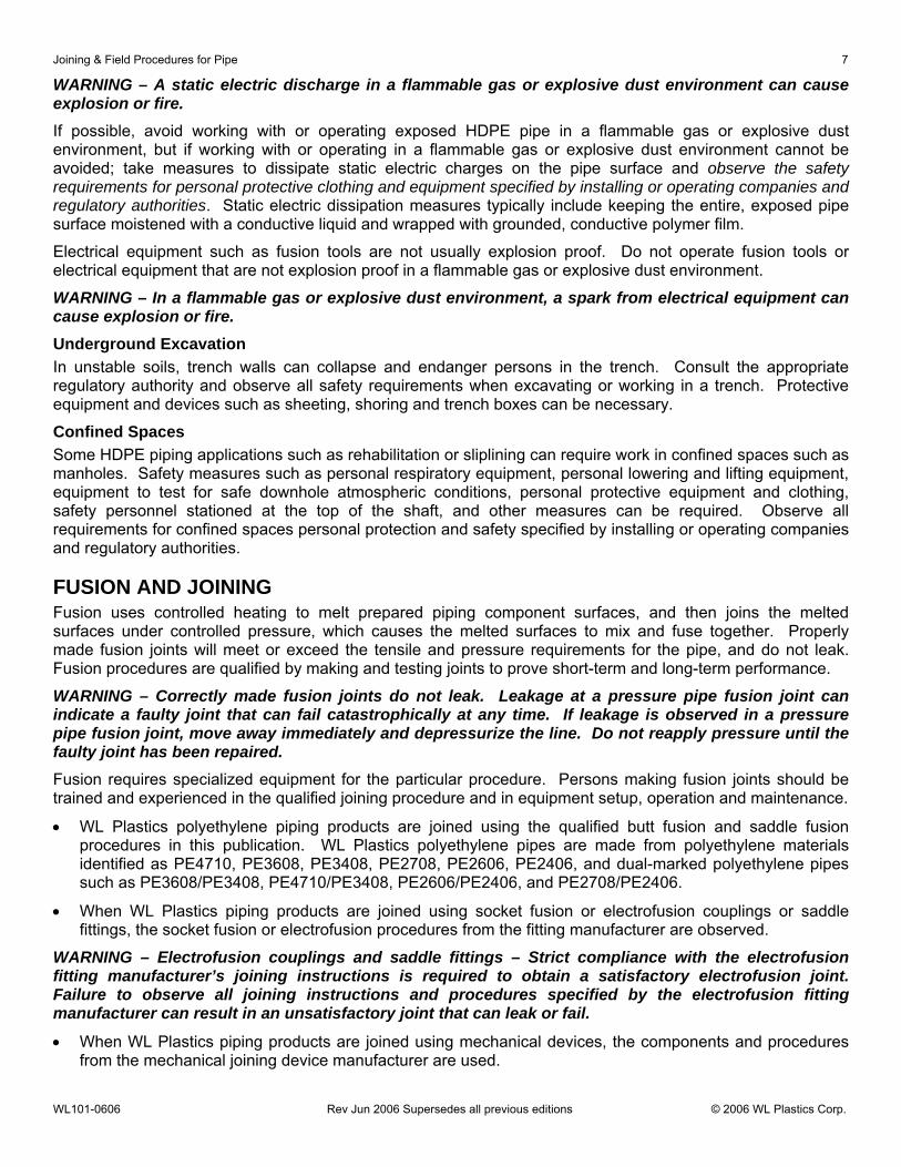
WARNING – A static electric discharge in a flammable gas or explosive dust environment can cause explosion or fire. If possible, avoid working with or operating exposed HDPE pipe in a flammable gas or explosive dust environment, but if working with or operating in a flammable gas or explosive dust environment cannot be avoided; take measures to dissipate static electric charges on the pipe surface and observe the safety requirements for personal protective clothing and equipment specified by installing or operating companies and regulatory authorities. Static electric dissipation measures typically include keeping the entire, exposed pipe surface moistened with a conductive liquid and wrapped with grounded, conductive polymer film.
Electrical equipment such as fusion tools are not usually explosion proof. Do not operate fusion tools or electrical equipment that are not explosion proof in a flammable gas or explosive dust environment.
WARNING – In a flammable gas or explosive dust environment, a spark from electrical equipment can cause explosion or fire. Underground Excavation In unstable soils, trench walls can collapse and endanger persons in the trench. Consult the appropriate regulatory authority and observe all safety requirements when excavating or working in a trench. Protective equipment and devices such as sheeting, shoring and trench boxes can be necessary.
Confined Spaces Some HDPE piping applications such as rehabilitation or sliplining can require work in confined spaces such as manholes. Safety measures such as personal respiratory equipment, personal lowering and lifting equipment, equipment to test for safe downhole atmospheric conditions, personal protective equipment and clothing, safety personnel stationed at the top of the shaft, and other measures can be required. Observe all requirements for confined spaces personal protection and safety specified by installing or operating companies and regulatory authorities.
FUSION AND JOINING Fusion uses controlled heating to melt prepared piping component surfaces, and then joins the melted surfaces under controlled pressure, which causes the melted surfaces to mix and fuse together. Properly made fusion joints will meet or exceed the tensile and pressure requirements for the pipe, and do not leak. Fusion procedures are qualified by making and testing joints to prove short-term and long-term performance.
WARNING – Correctly made fusion joints do not leak. Leakage at a pressure pipe fusion joint can indicate a faulty joint that can fail catastrophically at any time. If leakage is observed in a pressure pipe fusion joint, move away immediately and depressurize the line. Do not reapply pressure until the faulty joint has been repaired. Fusion requires specialized equipment for the particular procedure. Persons making fusion joints should be trained and experienced in the qualified joining procedure and in equipment setup, operation and maintenance.
• WL Plastics polyethylene piping products are joined using the qualified butt fusion and saddle fusion procedures in this publication. WL Plastics polyethylene pipes are made from polyethylene materials identified as PE4710, PE3608, PE3408, PE2708, PE2606, PE2406, and dual-marked polyethylene pipes such as PE3608/PE3408, PE4710/PE3408, PE2606/PE2406, and PE2708/PE2406.
• When WL Plastics piping products are joined using socket fusion or electrofusion couplings or saddle fittings, the socket fusion or electrofusion procedures from the fitting manufacturer are observed.
WARNING – Electrofusion couplings and saddle fittings – Strict compliance with the electrofusion fitting manufacturer’s joining instructions is required to obtain a satisfactory electrofusion joint. Failure to observe all joining instructions and procedures specified by the electrofusion fitting manufacturer can result in an unsatisfactory joint that can leak or fail.
• When WL Plastics piping products are joined using mechanical devices, the components and procedures from the mechanical joining device manufacturer are used.

8 Joining & Field Procedures for Pipe
WL101-0606 Rev Jun 2006 Supersedes all previous editions © 2006 WL Plastics Corp.
Liquid Hydrocarbon Permeated Pipe Liquid hydrocarbons such as crude oil, gasoline, kerosene, fuel oil, natural gas condensates and the like that are in the pipe or in surrounding soil will permeate into the pipe wall. Liquid hydrocarbon permeation generally has a minor effect on pipe that is already installed and joined. However, weak, unreliable joints can result when fusion is used to join polyolefin piping that has been permeated with liquid hydrocarbons.
In the field, liquid hydrocarbon permeation is indicated by a bubbly or pock-marked surface when the heating tool is removed during fusion joining. In some instances, the odor of the liquid hydrocarbon from the pipe or the surrounding soil or an enlarged pipe OD can be an indication.
Research indicates that joints made using pipes having moderate to higher levels of liquid hydrocarbon permeation will be unreliable, low-strength fusion joints. Low levels of liquid hydrocarbon permeation may not be as deleterious, but there are no quick field tests to determine the actual level of permeation.
When a bubbly or pock-marked appearance is observed in the melt surface during fusion or in fusion beads after fusion, the joint should be considered unreliable. Such joints should not be placed in service. When liquid hydrocarbon permeation is indicated, joining by an approved mechanical method should be used.
Butt Fusion Butt fusion joins plain end polyethylene pipes and fittings end to end without couplings, inserts or additional materials. This WL Plastics butt fusion joining procedure is consistent with and based on PPI TR-33 generic butt fusion joining procedure for joining compatible polyethylene piping products.
When joining WL Plastics polyethylene pipe to other polyethylene pipe or fittings, verify that PPI TR-33 generic butt fusion joining procedures are appropriate for use with the other products.
Pipes and other components joined using the WL Plastics butt fusion procedure must have the same outside diameter dimension specification and the difference between minimum wall thickness dimension specifications for the two components being joined should not exceed 26%, approximately 1 SDR.
(Minimum wall thickness dimension difference % = 100 (T1 - T2) / T2, where T1 = specified minimum wall dimension for greater wall thickness, and T2 = specified minimum wall dimension for lesser wall thickness. See WL102A, WL102B, WL104A and WL104B for minimum wall thickness information. SDR’s are 32.5, 26, 21, 17, 13.5, 11, 9, and 7.3. Contact WL Plastics if there are questions about joining unlike wall thickness.)
Butt fusion joining requires butt fusion equipment that holds the components in correct alignment and moves the components toward and away from each other during preparation, heating and joining operations. The equipment includes tools to face (plane) and heat the component ends.
• Butt fusion equipment is setup, operated and maintained in accordance with the equipment manufacturer’s instructions. Improperly setup, operated or maintained fusion equipment can produce faulty joints.
Other equipment such as pipe supports and appropriate equipment for handling pipe and fittings will be required.
Butt fusion equipment is manually operated for smaller size pipes and hydraulically operated for larger sizes. The equipment covers a range of pipe sizes, and must be setup for a pipe size by adjusting pipe holding clamps, setting the heating tool temperature, and for hydraulic equipment, by setting the fusion joining pressure. Additional setup will be required depending on the equipment. Follow the equipment manufacturer’s instructions for setup.
• Heating tool surface temperature – 400-450°F (204-232°C)
The heating tool surface temperature is the temperature of surfaces that actually contact the component ends. All heating tool surface contact areas should be within the specified temperature range. Heating tool surface temperature is verified with a pyrometer or an infrared temperature gauge (regular pyrometer and gauge calibration is recommended). Heating tools usually have a thermometer that reads internal temperature. Use the thermometer to monitor heating tool operation. A deviation in the thermometer reading can indicate faulty heating tool operation. The thermometer reading will be higher than surface temperature.
The heating tool surfaces that contact piping component ends have a non-stick coating or covering. The non-

Joining & Field Procedures for Pipe 9
WL101-0606 Rev Jun 2006 Supersedes all previous editions © 2006 WL Plastics Corp.
stick coating or covering must be clean and in good condition for proper fusion. Contamination such as plastic residue from previous fusions can be removed with wood sticks or clean, untreated, dry, lint-free non-synthetic cloths. Never use metal or abrasive implements to clean heating tool surfaces because these implements will damage the non-stick coating or covering. Burned or charred material should be removed in accordance with the equipment manufacturer’s instructions. Never apply chemicals to heating tool surfaces.
• Hydraulic fusion machine interface pressure – 60-90 psi (4.1-6.2 bar)
The interface pressure is used to determine equipment settings; it is not the setting. For hydraulically operated butt fusion machines, a joining force pressure setting is determined using a 60-90 psi (4.1-6.2 bar) interface pressure and the pipe diameter and DR. Internal machine friction and pipe drag pressures may be added to the joining pressure setting. Follow the equipment manufacturer’s instructions for determining and setting joining pressure for hydraulic butt fusion equipment.
Butt Fusion Procedure • Before starting the procedure, be sure portable generators are fueled up and heating tool surfaces are at
the prescribed temperature.
The steps for making a butt fusion joint are:
1. Secure the components in the butt fusion equipment;
2. Face (plane) the component ends;
3. Align the faced component ends;
4. Melt the component ends;
5. Join the melted component ends together, and apply and maintain joining pressure during cooling.
6. Inspect the completed joint.
Secure the Components in the Butt Fusion Equipment Clean the inside and outside of the pipe or fitting by wiping with a clean, untreated, dry, lint-free cloth. Remove all foreign material on the exterior area that will be clamped and inside the component end. Align the components to the machine clamps, and then securely clamp the components in the machine. The component ends need to extend past the clamps for facing and joining. Bring the clamped ends together and apply joining force to ensure that the components do not slip in the clamps. Release joining pressure and adjust vertical component end alignment by tightening the high side clamp. Never loosen the low side clamp or the component may slip during joining.
WARNING – Never force pipe ends into alignment against open butt fusion equipment clamps. The pipe can spring out of the open clamp, causing death or injury. Always align the pipe to the clamps, place the pipe in the clamps and then securely clamp the pipe in the equipment. Note – Coiled pipe is usually slightly oval from winding pipe into a coil. Ovality can be minimized or removed by pulling coiled pipe through commercially available straightening and rerounding equipment. (ASTM D 2513 requires the installer to straighten and reround.) See the section on Subfreezing and Inclement Weather Conditions earlier in this publication. Coiled pipe that is not straightened and rerounded should be oriented in the butt fusion machine clamps so that the wide part of the oval is vertical. Tightening the clamps will then reround the pipe at the joint. It can be easier to secure coiled pipes in butt fusion equipment if the coils are oriented to make an “S” curve through the butt fusion machine; that is, with pipe on one end of the joint curving to the left, and the pipe on the opposite end curving to the right.
Face the Component Ends The pipe ends are faced (planed) to establish clean, parallel mating surfaces for heating and joining. Butt fusion equipment includes a facing tool that is placed between the component ends. The facing tool has rotating blades on both sides that simultaneously plane material from both component ends.
Move the component ends away from each other, install the facing tool between the ends, turn it on, and move the component ends against the facing tool. Face the component ends until continuous shavings are produced

10 Joining & Field Procedures for Pipe
WL101-0606 Rev Jun 2006 Supersedes all previous editions © 2006 WL Plastics Corp.
from both component ends, and the distance between the component ends is the gap specified by the equipment manufacturer. When facing is complete, stop moving the component ends against the facing tool, and then turn the facing tool off when shavings are no longer being produced. Separate the component ends and remove the facing tool.
With a clean, untreated, dry, lint-free cloth, remove shavings and chips from the component ends, inside and out, and from the equipment area between the component ends.
Caution – To avoid contamination, never touch faced component ends with bare hands. Align the Faced Component Ends After all shavings have been cleared, move the component ends together and if necessary, adjust the component ends so that the tops are aligned. Always adjust the high side down to the low side by tightening the high side clamp. Never loosen the low side clamp or components may slip during joining.
If high-low adjustment is made, reinstall the facing tool, briefly reface the component ends, and remove all shavings using a clean, untreated, dry, lint-free cloth.
Melt the Component Ends Check the heating tool to be sure the heating tool surfaces are clean and at the prescribed temperature of 400-450°F (204-232°C).
Caution – Hot heating tool surfaces and melted component ends can cause burns. Heat protective gloves and appropriate heat protective clothing is recommended. Install the hot, clean heating tool between the component ends, and move the component ends together and against the heating tool surfaces. Initial contact is made with brief moderate force to ensure complete contact between component ends and heating tool surfaces. Immediately after complete initial contact has been assured, reduce force so that contact (zero pressure) is maintained, but do not force component ends against heating tool surfaces.
As the component ends heat and melt, beads of molten material will form and expand against the heating tool surface around the component ends.
• Heating time is determined by melt bead size. (Table 1)
Note – Do not force component ends against heating tool surfaces during heating. Force during heating can be indicated by melt beads curling away from heating tool surfaces.
Note – For hydraulic butt fusion equipment, the sequence of control valve operation for carriage movement and pressure control is very important. An improper “shift sequence” can apply force during heating, and cause a weak, unreliable joint. To avoid force during heating, operate hydraulic control valves in accordance with equipment manufacturer’s instructions.
Maintain no-force contact between the component ends and the heating tool while beads of molten polyethylene form and expand on the heating tool surfaces at the component ends. Heating time is determined by melt bead size as specified in Table 1. For larger piping, melt bead size may be gauged using short lengths of appropriately sized wood dowel rod.
• Heating time ends when the Table 1 melt bead size has formed all around both component ends.
Joining & Field Procedures for Pipe 11
WL101-0606 Rev Jun 2006 Supersedes all previous editions © 2006 WL Plastics Corp.
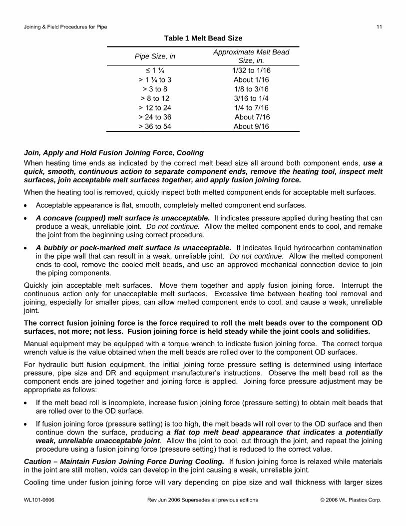
Table 1 Melt Bead Size
Pipe Size, in Approximate Melt Bead Size, in.
≤ 1 ¼ 1/32 to 1/16 > 1 ¼ to 3 About 1/16
> 3 to 8 1/8 to 3/16 > 8 to 12 3/16 to 1/4
> 12 to 24 1/4 to 7/16 > 24 to 36 About 7/16 > 36 to 54 About 9/16
Join, Apply and Hold Fusion Joining Force, Cooling When heating time ends as indicated by the correct melt bead size all around both component ends, use a quick, smooth, continuous action to separate component ends, remove the heating tool, inspect melt surfaces, join acceptable melt surfaces together, and apply fusion joining force. When the heating tool is removed, quickly inspect both melted component ends for acceptable melt surfaces.
• Acceptable appearance is flat, smooth, completely melted component end surfaces.
• A concave (cupped) melt surface is unacceptable. It indicates pressure applied during heating that can produce a weak, unreliable joint. Do not continue. Allow the melted component ends to cool, and remake the joint from the beginning using correct procedure.
• A bubbly or pock-marked melt surface is unacceptable. It indicates liquid hydrocarbon contamination in the pipe wall that can result in a weak, unreliable joint. Do not continue. Allow the melted component ends to cool, remove the cooled melt beads, and use an approved mechanical connection device to join the piping components.
Quickly join acceptable melt surfaces. Move them together and apply fusion joining force. Interrupt the continuous action only for unacceptable melt surfaces. Excessive time between heating tool removal and joining, especially for smaller pipes, can allow melted component ends to cool, and cause a weak, unreliable joint. The correct fusion joining force is the force required to roll the melt beads over to the component OD surfaces, not more; not less. Fusion joining force is held steady while the joint cools and solidifies. Manual equipment may be equipped with a torque wrench to indicate fusion joining force. The correct torque wrench value is the value obtained when the melt beads are rolled over to the component OD surfaces.
For hydraulic butt fusion equipment, the initial joining force pressure setting is determined using interface pressure, pipe size and DR and equipment manufacturer’s instructions. Observe the melt bead roll as the component ends are joined together and joining force is applied. Joining force pressure adjustment may be appropriate as follows:
• If the melt bead roll is incomplete, increase fusion joining force (pressure setting) to obtain melt beads that are rolled over to the OD surface.
• If fusion joining force (pressure setting) is too high, the melt beads will roll over to the OD surface and then continue down the surface, producing a flat top melt bead appearance that indicates a potentially weak, unreliable unacceptable joint. Allow the joint to cool, cut through the joint, and repeat the joining procedure using a fusion joining force (pressure setting) that is reduced to the correct value.
Caution – Maintain Fusion Joining Force During Cooling. If fusion joining force is relaxed while materials in the joint are still molten, voids can develop in the joint causing a weak, unreliable joint.
Cooling time under fusion joining force will vary depending on pipe size and wall thickness with larger sizes
12 Joining & Field Procedures for Pipe
WL101-0606 Rev Jun 2006 Supersedes all previous editions © 2006 WL Plastics Corp.
and thicker walls taking longer. The joint may be carefully removed from butt fusion equipment and handled gently when the external butt fusion bead is cool enough to maintain bare hand contact without discomfort (cooled down to about 120-130°F or lower).
• Do not apply water or wet cloths to the joint because it can result in weak, unreliable joints.
(An equipment-controlled chilled air fusion procedure system that has been qualified by testing in accordance with ASTM D2657, PPI TR-33, and Codes such as 49 CFR Part 192 or ANSI B31 is acceptable.) • When removed from the butt fusion equipment, additional, undisturbed cooling time is required before
pulling, rough handling or installation.
• The overall cooling time is 30 to 90 seconds per inch of pipe diameter, with thicker walls (lower DR’s) taking longer cooling times.
Visually Inspect Fusion Bead Appearance Correctly made butt fusion joints have cooled melt beads that are:
• Rolled over to the component OD surface;
• Uniform in size and shape all around the joint;
• Rounded on the top;
• The combined width of the beads should be 2 to 2 ½ times the height above the component OD surface;
• The v-groove between the beads should not be deeper than half the bead height above the component OD surface.
Incorrectly made butt fusion joints can be weak and unreliable, and should not be placed in service. Cut the joint out and remake the butt fusion from the beginning using correct procedure. Indications and possible causes of incorrect butt fusion procedure that could produce a weak, unreliable joint are:
• Beads not rolled over to the OD surface – Insufficient joining force when the v-groove is shallow, or insufficient heating and excessive joining force when the v-groove is deep.
• Non-uniform bead size or shape around the joint, or one bead larger than the other – Misalignment; defective heating tool (cold spots); worn butt fusion equipment (allows components to shift out of alignment); incomplete facing or defective facing tool (dull or damaged blades); component slipped in clamps.
• Beads flat on the top – Heating too long or excessive joining force.
• Beads with a squareish outer edge – Pressure during heating.
• Beads too large or too small – Excessive heating time (beads too large); inadequate heating or joining force (beads too small).
• V-groove between beads too deep – Pressure during heating; Insufficient heating or excessive joining force.
• Pockmarked or bubbly bead appearance – Liquid hydrocarbon contamination. (Cut the butt fusion out and use a mechanical joining method.)
Approximate Butt Fusion Joining Rates Table 2 presents approximate daily butt fusion joining rates. Actual jobsite joining rates will vary depending on pipe size and wall thickness (DR), jobsite conditions, product staging, equipment condition, crew size and experience, and handling equipment. Table 2 rates are approximate for estimating purposes only and do not include time for equipment setup, string to string tie-in joints or butt fusion in the trench that require additional time. Lower DR pipes have longer fusion times because there is more material to heat and cool.

Joining & Field Procedures for Pipe 13
WL101-0606 Rev Jun 2006 Supersedes all previous editions © 2006 WL Plastics Corp.
Table 2 Approximate Field Joining Rates – Butt Fusion
Nominal Pipe Size, in Fusions per Day ≤ 10
10 – 18 18 – 24 24 – 36 36 – 48
54
15 – 40 10 – 24 6 – 16 5 – 15 4 –10 3 –8
Bead Removal Butt fusion produces a bead of material on the inside of the pipe as well as on the outside. For pressure piping applications, internal beads have negligible flow effects. Internal bead effects are incorporated in recommended flow resistance factors for WL Plastics polyethylene pipe used with engineering formulas such as Hazen-Williams, Manning, Moody, Colebrook, Darcy-Weisback, Mueller, etc. See WLPipeCalc™ and WL120. The cost of internal bead removal is seldom justified because fusions must be completely cooled before bead removal. Removing beads before complete cooling can result in a notch at the joint that can cause premature failure at the joint. External beads are sometimes removed for installation and rehabilitation methods where the pipe must fit closely inside a casing or host pipe.
• Fusion joints must be completely cool before bead removal. Bead removal before complete cooling can cause premature failure at the joint.
• Bead removal must never extend into or below the pipe surface. Cuts into the pipe surface can cause premature failure at the joint.
• Joints are inspected for correct bead size and shape before external bead removal.
• Internal bead removal can significantly increase joining and installation time.
Saddle (Sidewall) Fusion Saddle fusion joins a curved base fitting to the top or side of a main pipe to provide a service or branch outlet. Saddle fusion can be performed on pressurized and non-pressurized main pipes. This WL Plastics saddle fusion joining procedure is consistent with and based on the PPI TR-41 generic saddle fusion joining procedure for joining compatible polyethylene piping products.
When joining WL Plastics polyethylene pipe to saddle fusion fittings, verify that PPI TR-41 generic butt fusion joining procedures can be used for joining the saddle fusion fittings.
This procedure assumes saddle fusion to a pressurized main, and is conservative if the main is not pressurized. Pressurized mains can blow out if main size, pressure or temperature limits are exceeded, if heating is excessive, if step sequence is not followed, or if too much time is taken between steps.
Limits for saddle fusion to pressurized gas mains are:
• Maximum internal main pressure in accordance with U.S. D.O.T. plastic pipe pressure design regulations (192.121 - 192.123) using 0.32 design factor for all class locations;
• Maximum main pipe temperature 73°F;
• 1 ¼” IPS and 2” IPS main pipe, DR 11 and lower;
• 3” IPS main pipe, DR 13.5 and lower;
• 4” IPS main pipe and larger, DR 17 and lower.
The limit for saddle fusion to pressurized water mains is
• Maximum internal pressure not exceeding the pipe Pressure Class (PC) for water and main pipe temperature at 80°F or lower.

14 Joining & Field Procedures for Pipe
WL101-0606 Rev Jun 2006 Supersedes all previous editions © 2006 WL Plastics Corp.
Required Equipment Saddle Fusion Tool–a tool that installs on the main, holds and aligns the fitting to the main pipe; moves the fitting to and away from the main pipe; and indicates the force applied when the fitting is moved against the heating tool or the main.
Heating Tool–a heating tool fitted with curved, non-stick surfaces that match main pipe curvature, and are sized and shaped slightly larger than the fitting base.
A support or bolster plate that is clamped to 6” IPS and smaller main pipe opposite the fitting installation area.
50-60 grit utility cloth. Do not use sandpaper. It will leave a residue on the surface. Worn utility cloth must be replaced.
A stopwatch or watch with a sweep second hand for saddle fusion to pressurized 2” IPS and smaller mains.
Optional Equipment Flexible Heat Shield – a flexible heat resistant metal or fabric pad used to help establish a melt pattern on larger mains.
Saddle Fusion Terms The terms used in this procedure and in PPI TR-41 generic saddle fusion procedures are the same.
Initial Heat (Bead-up) – The heating step used to develop an initial melt bead on the main pipe.
Initial Heat Force (IHF, Bead-up force) – The force (in pounds) applied to establish an initial melt pattern on the main pipe. Initial Heat Force is determined by multiplying the fitting base area (sq. inches) by the initial interfacial pressure (pounds per square inch).
• Initial Interfacial Pressure – 60 psi
Heat Soak Force (HSF) – The force (in pounds) applied after an initial melt pattern is established on the main pipe. The Heat Soak Force is the minimum force (essentially zero pounds) necessary to ensure that the fitting, heater and main stay in contact with each other.
Fusion Force (FF) – The force (in pounds) applied to establish the fusion bond between the fitting and the pipe. Fusion Force is determined by multiplying the fitting base area (square inches) by the fusion interfacial pressure (pounds per square inch).
• Fusion Interfacial Pressure – 30 psi
Total Heat Time – A time that starts when the heating tool is placed on the main pipe and initial heat force is applied and that ends when the heating tool is removed.
Table 3 Total Heat Time
Main Size Maximum Total Heat Time
1 ¼” IPS, all DR’s
Non-pressure & water main–Total Heat Time ends when 1/16” melt bead is visible all around fitting base. Pressurized gas main–15 seconds Maximum Total Heat Time.
2” IPS, all DR’s
Non-pressure & water main–Total Heat Time ends when 1/16” melt bead is visible all around fitting base. Pressurized gas main–35 seconds Maximum Total Heat Time.
3” IPS and larger
Total Heat Time ends when 1/16” melt bead is visible all around fitting base.
Cool Time – The time required to cool the joint to approximately 120°F (49°C). The fusion force must be
Joining & Field Procedures for Pipe 15
WL101-0606 Rev Jun 2006 Supersedes all previous editions © 2006 WL Plastics Corp.
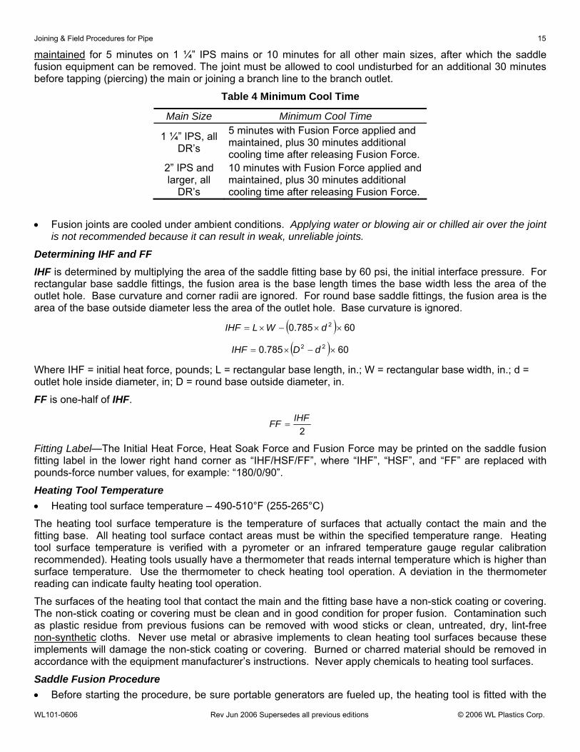
maintained for 5 minutes on 1 ¼” IPS mains or 10 minutes for all other main sizes, after which the saddle fusion equipment can be removed. The joint must be allowed to cool undisturbed for an additional 30 minutes before tapping (piercing) the main or joining a branch line to the branch outlet.
Table 4 Minimum Cool Time
Main Size Minimum Cool Time
1 ¼” IPS, all DR’s
5 minutes with Fusion Force applied and maintained, plus 30 minutes additional cooling time after releasing Fusion Force.
2” IPS and larger, all
DR’s
10 minutes with Fusion Force applied and maintained, plus 30 minutes additional cooling time after releasing Fusion Force.
• Fusion joints are cooled under ambient conditions. Applying water or blowing air or chilled air over the joint is not recommended because it can result in weak, unreliable joints.
Determining IHF and FF IHF is determined by multiplying the area of the saddle fitting base by 60 psi, the initial interface pressure. For rectangular base saddle fittings, the fusion area is the base length times the base width less the area of the outlet hole. Base curvature and corner radii are ignored. For round base saddle fittings, the fusion area is the area of the base outside diameter less the area of the outlet hole. Base curvature is ignored.
( ) 60785.0 2 ××−×= dWLIHF
( ) 60785.0 22 ×−×= dDIHF
Where IHF = initial heat force, pounds; L = rectangular base length, in.; W = rectangular base width, in.; d = outlet hole inside diameter, in; D = round base outside diameter, in.
FF is one-half of IHF.
2IHFFF =
Fitting Label—The Initial Heat Force, Heat Soak Force and Fusion Force may be printed on the saddle fusion fitting label in the lower right hand corner as “IHF/HSF/FF”, where “IHF”, “HSF”, and “FF” are replaced with pounds-force number values, for example: “180/0/90”.
Heating Tool Temperature • Heating tool surface temperature – 490-510°F (255-265°C)
The heating tool surface temperature is the temperature of surfaces that actually contact the main and the fitting base. All heating tool surface contact areas must be within the specified temperature range. Heating tool surface temperature is verified with a pyrometer or an infrared temperature gauge regular calibration recommended). Heating tools usually have a thermometer that reads internal temperature which is higher than surface temperature. Use the thermometer to check heating tool operation. A deviation in the thermometer reading can indicate faulty heating tool operation.
The surfaces of the heating tool that contact the main and the fitting base have a non-stick coating or covering. The non-stick coating or covering must be clean and in good condition for proper fusion. Contamination such as plastic residue from previous fusions can be removed with wood sticks or clean, untreated, dry, lint-free non-synthetic cloths. Never use metal or abrasive implements to clean heating tool surfaces because these implements will damage the non-stick coating or covering. Burned or charred material should be removed in accordance with the equipment manufacturer’s instructions. Never apply chemicals to heating tool surfaces.
Saddle Fusion Procedure • Before starting the procedure, be sure portable generators are fueled up, the heating tool is fitted with the

16 Joining & Field Procedures for Pipe
WL101-0606 Rev Jun 2006 Supersedes all previous editions © 2006 WL Plastics Corp.
correct adapters for the pipe and the fitting, and the heating tool is at the prescribed temperature.
The steps for making a saddle fusion joint are:
1. Preparation
2. Heating
3. Fusion and Cooling
4. Visually Inspect Fusion Bead Appearance
Preparation • Install the Saddle Fusion Tool on the main according to the equipment manufacturer’s instructions. The tool
is centered over a clean, dry location where the fitting will be fused. For 6” IPS and smaller main sizes, a main bolster or support is installed against the main opposite the fitting location.
• Abrade the main surface where the fitting will be fused with 50-60 grit utility cloth. A thin layer of the pipe surface must be completely removed, and the abraded area must be larger than the area covered by the fitting base. Brush residue away with a clean, dry cloth. Do not touch the abraded surface with bare hands.
• Abrade the fusion surface of the fitting base with 50 to 60 grit utility cloth. A thin layer of the fitting base must be completely removed. Brush dust and residue away with a clean, dry cloth. Do not touch the abraded surface with bare hands.
• Loosely install the fitting in the Saddle Fusion Tool and move the fitting base against the main pipe. Apply about 100 pounds-force to seat the fitting on the main, and secure the fitting in the Saddle Fusion Tool.
Heating Caution – Hot heating tool surfaces and melted pipe and fitting surfaces ends can cause burns. Wear heat protective gloves and appropriate heat protective clothing.
For smaller branch and service saddles on smaller mains:
• In a quick, continuous action, place the heating tool on the main centered beneath the fitting base, move the fitting against the heating tool, apply the Initial Heat Force, and start the heat time. Apply the Initial Heat Force until melt is first visible on the crown of the main pipe (usually 3-5 seconds), and then immediately reduce applied force to the Heat Soak Force (usually zero). Maintain the Heat Soak Force until the Total Heat Time ends. See Table 3.
For larger branch saddles on larger mains:
• (This step usually requires an assistant to handle the Flexible Heat Shield.) Place the heating tool on the main centered beneath the fitting base, and then place the Flexible Heat Shield between the heating tool and the fitting base. Move the fitting against the Flexible Heat Shield, apply Initial Heat Force, and observe melt bead formation on the main all around the heating tool. When a melt bead is first visible on the main all around the heating tool, in a quick continuous motion, release Initial Heat Force, raise the fitting slightly, remove the flexible Heat Shield, move the fitting against the heating tool, apply Initial Heat Force and start the heat time. When a melt bead is first visible all around the fitting base (usually about 3-5 seconds), immediately reduce applied force to the Heat Soak Force (usually zero). Maintain the Heat Soak Force until the Total Heat Time ends. See Table 3.
Important – During heating, hold the heating tool in position by lightly supporting the heating tool handle. If not supported, the heating tool can slip out of position or displace the main or fitting melt and result in a poor joint.
Fusion and Cooling At the end of the Total Heat Time – in a quick, continuous action – separate the fitting from the heating tool and the heating tool from the main, quickly check melt patterns on the main and the fitting base, move the fitting against the main, and apply Fusion Force.

Joining & Field Procedures for Pipe 17
WL101-0606 Rev Jun 2006 Supersedes all previous editions © 2006 WL Plastics Corp.
• Different manufacturer’s Saddle Fusion Tools can require different techniques for separating the heating tool from the fitting and the main without damaging melted surfaces. Observe the Saddle Fusion Tool manufacturer’s recommended technique.
• Acceptable melt appearance is completely melted surfaces with no unmelted areas (cold spots).
• A bubbly or pockmarked melt surface on the main indicates unacceptable hydrocarbon contamination.
Regardless of melt appearance, continue with the procedure – move the fitting against the main and apply Fusion Force. The fitting should be moved against the main and Fusion Force applied within 3 seconds of heating tool removal. Fuse the saddle fitting to the main even if melt surfaces are unacceptable because heat continues to travel through the main wall after heating tool has been removed. Fusing the saddle fitting reinforces the heated area of the main against blowout.
Maintain Fusion Force for the minimum cooling time specified in Table 4. The Saddle Fusion Tool may be removed after Fusion Force is relaxed. After relaxing Fusion Force, cool for an additional 30 minutes before connecting the saddle fitting branch outlet to a service line or piercing (tapping) the main.
Visually Inspect Fusion Bead Appearance • The saddle fusion joint is unacceptable if melted surfaces were unacceptable. To prevent use, cut the
fitting off at or just above the base.
Visually inspect the fusion beads around the fitting base. Typically, there are three beads, a melt bead around the fitting base, a bead on the main from the edge of the Heating Tool, and a main pipe melt bead. The fitting and pipe melt beads should be rounded and about 1/8” wide all around the fitting base. The heating tool edge bead should be visible all around the fitting base, but may be separate from the main pipe melt bead.
• The saddle fusion joint is unacceptable for use if visual bead appearance is unacceptable. To prevent use, cut the fitting off at or just above the base.
Indications and possible causes of incorrect saddle fusion procedure that could produce a weak, unreliable joint are:
• Non-uniform bead size or shape around the fitting base or one bead larger than the other – misalignment; fitting or pipe slipped in Saddle Fusion Tool; worn equipment; defective heating tool; loose or contaminated heating tool faces; improper heating tool removal technique.
• Beads too small – Insufficient heating; insufficient Fusion Force.
• Beads too large – Excessive heating time; excessive Fusion Force.
• No heating tool melt bead or heating tool melt bead partially missing – heating tool pipe face too small; Heating tool not properly centered to fitting base.
• Pressurized gas main blowout – Excessive heating time; incorrect heating tool faces; low heating tool temperature; excessive time between placing heating tool on main and moving fitting against heating tool; excessive time between heating tool removal and moving fitting against main pipe; main pipe above 73°F for gas or 80°F for water; main pipe DR too high.
• Bubbly or pockmarked main bead appearance–liquid hydrocarbon contamination of the main pipe that can cause a weak, unreliable joint. To prevent use, cut the fitting off at or just above the base, and install an approved mechanical saddle outlet on the main nearby to make the branch connection.
Socket Fusion and Electrofusion WL Plastics polyethylene pipe can be joined using socket fusion and electrofusion fittings. Obtain socket fusion and electrofusion joining procedures and instructions from the fitting manufacturer, and use the fittings, tools equipment and procedures specified by the fitting manufacturer.
WARNING – Electrofusion couplings and saddle fittings – Strict compliance with the electrofusion fitting manufacturer’s joining instructions is required to obtain a satisfactory electrofusion joint. Failure to observe all joining instructions and procedures specified by the electrofusion fitting

18 Joining & Field Procedures for Pipe
WL101-0606 Rev Jun 2006 Supersedes all previous editions © 2006 WL Plastics Corp.
manufacturer can result in an unsatisfactory joint that can leak or fail. Fusion Training and Proficiency Field fusion joints should be made by trained, experienced persons who have demonstrated that they can produce sound joints using the joining procedure and equipment. Proficiency is demonstrated by providing written proof that the person received training in the applicable fusion procedure and that the individual made fusion joints that were tested and found acceptable.
Proficiency testing of fusion joints typically includes visual inspection and destructive mechanical tests such as bent strap test or tensile tests. Visual inspection guidelines are presented in the butt and saddle fusion procedures.
Specimens for bent strap tests are cut from trial butt or saddle fusions as illustrated in Figures 1 and 2. The cut through the fusion should be visually examined. Voids or disbonded areas are unacceptable. The specimens are then bent so that the ends of the strap touch. Failure or disbondment at the fusion is unacceptable.
Tensile tests are conducted in accordance with ASTM D638 by applying a tensile load across a section of the fusion using tensile specimens cut from a trial fusion and from pipe adjacent to the trial fusion. See Figure 3. Tensile test results for fusion tensile specimens should compare favorably with tensile yield, elongation and break strengths for pipe tensile specimens, and there should not be disbondment at the fusion. (Note – Cut edges of tensile specimens should be smooth without tool marks. External fusion beads may need to be removed from fusion tensile test specimens.)
Other tests can include ASTM D1598 sustained internal pressure tests using the sustained pressure test conditions required for pipe under the applicable pipe manufacturing standard (ASTM D2513, D3035 or F714, AWWA C901 or C906, API 15LE, etc.) Elevated temperature (176°F/80°C) sustained pressure tests are typically preferred because test results can be determined in a shorter time compared to 73°F/23°C sustained pressure tests. Sustained pressure test specimens should be prepared with the fusion in the center of the specimen length, and have at least 3 pipe diameters length from each side of the fusion to specimen end closures. Saddle fusions can be evaluated in accordance with ASTM F905.
Figure 1 Butt Fusion Bent Strap Test Specimen
Figure 2 Saddle Fusion Bent Strap Test Specimen

Joining & Field Procedures for Pipe 19
WL101-0606 Rev Jun 2006 Supersedes all previous editions © 2006 WL Plastics Corp.
Figure 3 Butt Fusion Tensile Specimen
Data Logging Some butt fusion and saddle fusion equipment can provide electronic time, temperature and pressure signals while fusions are being made that can be recorded by data logging (data recording and storage) devices. Data records can be compared to fusion procedure requirements to help identify and correct improper joining procedure. In the event of questionable field fusions, data records can help identify potentially good or bad fusions, and provide a field fusion quality record for the installation.
Electrofusion Electrofusion couplings and saddle fittings have electric heating elements embedded in each end of the coupling or in the saddle base. Component preparation and joining must be in strict accordance with the electrofusion fitting manufacturer’s instructions. Improper preparation or joining procedure can result in joint leakage or failure. Persons making electrofusion joints should be trained and qualified in the electrofusion fitting manufacturer’s joining procedure.
WARNING – Electrofusion couplings and saddle fittings – Strict compliance with the electrofusion fitting manufacturer’s joining instructions is required to obtain a satisfactory electrofusion joint. Failure to observe all joining instructions and procedures specified by the electrofusion fitting manufacturer can result in an unsatisfactory joint that can leak or fail. Extrusion and Hot-Air (Hot-Gas) Welding Extrusion welding heats prepared component ends, and than extrudes a bead of melted polyethylene between the prepared, preheated surfaces. Extrusion welding is frequently used for large, non-pressure fabrications such as manholes. However, even the best made extrusion welds cannot develop the strength and long-term performance required for pressure piping service.
WARNING – Never use extrusion welding to make joints in WL Plastics polyethylene pressure piping systems. Hot-air (hot-gas) welding preheats prepared component ends with a hot gas, and feeds a rod of plastic material into the heated area. The hot-gas heats and melts the component surfaces and the welding rod together.
The plastic material used for WL Plastics polyethylene pipe is not suitable for hot-air (hot-gas) welding.
Warning – Never use hot-air (hot-gas) welding to join WL Plastics polyethylene pipe. Tapered Pipe Threads Polyethylene pipe is generally too ductile for successful joining with tapered pipe threads. Taper pipe threads are easily cross threaded and stripped, and are unsuitable for pressure systems.
Warning – Do not use tapered pipe threads to make joints in WL Plastics pressure piping systems. Mechanical Connections Mechanical joining devices for end to end and branch connections are available from other manufacturers for use with polyethylene pipe. Depending on design, mechanical connections can provide leak-tightness and full or partial restraint against pullout disjoining. Full restraint is such that tensile load will cause the pipe to yield before disjoining. Partial restraint resists disjoining under tensile load, but disjoining will occur before the pipe yields. Partial restraint can also be provided with separate mechanical devices installed across the mechanical
20 Joining & Field Procedures for Pipe
WL101-0606 Rev Jun 2006 Supersedes all previous editions © 2006 WL Plastics Corp.
connection.
Consult the mechanical connection manufacturer about suitability for use with polyethylene pipe, leak-tightness, and restraint. Do not use mechanical connection devices that are not intended for use with polyethylene pipe.
• Mechanical connections are always installed in accordance with the mechanical connection manufacturer’s instructions.
Mechanical connections that do not provide sufficient resistance to tensile pullout are not suitable for use with WL Plastics polyethylene pipe. Heat fused polyethylene piping will transmit thermal contraction and Poisson effect tensile loads from length to length along the piping run. The cumulative load can disjoin unrestrained or inadequately restrained in-line mechanical connections at the end of the run. Full restraint is necessary for some applications, but many applications can successfully utilize mechanical connections that provide or are fitted with external mechanical restraint that exceeds the pullout load that may develop.
Thrust blocks used for bell and spigot joined piping systems are not suitable or effective joint restraints for polyethylene piping systems. Thrust blocks are designed to keep bell and spigot joint components from being pushed off the pipe end, but have no capacity to keep pipe from being pulled out of the joint.
Fully restrained, leak-tight mechanical connections can include flange adapters and stub ends, mechanical joint (MJ) adapters, transition fittings, and some compression couplings.
Flange adapters and stub ends are butt fused to PE pipe, and can be used to join PE to other piping materials. Flange adapters have an extended hub for clamping in butt fusion equipment. Stub ends have a short hub, and require special stub end holders for butt fusion. Flanges require back-up rings that carry the bolts and distribute bolting pressure uniformly over the sealing surface. Flange connections must be installed, aligned and tightened in accordance with the flange manufacturer’s instructions, and must be protected against shear and bending loads. Some flanges have serrated sealing surfaces that under certain conditions do not require gaskets for a leak-tight seal.
Mechanical joint (MJ) Adapters are used in water systems to connect to mechanical joint fittings, appurtenances and pipe. Standard MJ connection gaskets and glands are used with extended length bolts.
Transition fittings are typically factory made polyethylene to metal pipe connections that are heat fused to polyethylene pipe, and welded or mechanically joined to metal pipe.
Restrained mechanical compression couplings use a stiffener or tubular insert in the pipe bore, and components that grip the pipe wall and compress the pipe OD against the ID stiffener or tubular insert. Gaskets provide leak tightness.
Some mechanical coupling devices have teeth that dig into the pipe OD. Depending on the design, some restraint against pullout can be provided. Devices that use only screw in lugs or setscrews generally provide very low pullout resistance with polyethylene pipe. The device manufacturer should be consulted for pullout load resistance, which should be compared against the pullout load that may develop.
For some mechanical coupling devices, restraint can be provided with clamp and tie rod devices. These external restraint devices are usually more effective when pipe bore stiffeners extend under the clamp.
Mechanical branch outlet connections are typically sleeve or saddle designs. Sleeve designs wrap completely around the main pipe and use bolted seam closures. Gaskets that encircle the main pipe or encircle the outlet hole provide leak tightness.
Saddle branch outlet designs cover part of the main pipe surface and use straps or bands to secure the saddle to the pipe. Gaskets encircling the branch outlet seal against leakage. For PE pipe, wide saddles with multiple straps or bands should be used.
TESTING Field Leak Testing ASTM standards are recommended for conducting leak tests of installed WL Plastics piping systems.

Joining & Field Procedures for Pipe 21
WL101-0606 Rev Jun 2006 Supersedes all previous editions © 2006 WL Plastics Corp.
• ASTM F1417 Installation Acceptance of Plastic Gravity Sewer Lines Using Low-Pressure Air
• ASTM F2164 Field Leak Testing of Polyethylene (PE) Pressure Piping Systems Using Hydrostatic Pressure
ASTM F1417 uses low pressure (3.5 psi) air to determine if leaks exist in an installed plastic gravity sewer piping system.
ASTM F2164 uses a pressurized liquid (clean water) to determine if leaks exist in an installed polyethylene pressure piping system.
• Polyethylene piping systems that convey liquids under pressure are tested with liquids (hydrostatic testing).
WARNING – Failure during leak testing can cause the sudden, violent movement of pipe, components or surrounding materials that can kill or injure persons in their path. Pipes and components shall be restrained before and during testing such that any movement from failure does not endanger persons. WARNING – Correctly made fusion joints do not leak. Leakage at a fusion can immediately precede sudden joint separation. If leakage is observed at a fusion joint, move away immediately and depressurize the line. Repair (cut out and replace) the fusion joint before pressure is reapplied.
Never attempt to repair leaks while piping is under pressure. Always depressurize piping before making repairs.
Pneumatic Tests • Pneumatic (compressed gas) testing is never substituted for hydrostatic testing.
WARNING – Testing with a compressed gas (pneumatic testing) is dangerous. Pipe connection or closure failure can explosively release pipe pressurizing energy and gas compression energy, causing violent movement of pipes, parts or surrounding materials that can kill or injure persons in their path.
• For safety reasons, WL Plastics does not provide a pneumatic (compressed gas) testing procedure for PE pressure piping systems.
• If pneumatic testing is specified, the owner or operator of the system provides the testing procedure and is solely responsible for ensuring that testing is conducted safely and in accordance with the owner or operator’s procedure.
Field Pressure Testing Field pressure testing to verify the pressure capacity of polyethylene piping is not recommended. The pressure capacity (Pressure Rating or Pressure Class) of WL Plastics polyethylene pipe is determined using long-term testing and analysis in accordance with ASTM and PPI standards. Pressure Rating or Class cannot be verified with short term field pressure tests.
The design capacity of a polyethylene piping system for an application is determined by the piping system designer. Application design parameters cannot be verified with post-installation short term field pressure tests. Therefore, field pressure tests serve no purpose.
INSTALLATION • Buried gravity flow piping is installed per ASTM D2321 Underground Installation of Thermoplastic Pipe for
Sewers and Other Gravity-Flow Applications.
• Buried pressure piping is installed per ASTM D2774 Underground Installation of Thermoplastic Pressure Piping.
• Contact WL Plastics for technical information. WL Plastics does not provide design or engineering services.
REPAIR Polyethylene pipe is tough, but not immune to damage. Depending on the nature of the damage and

22 Joining & Field Procedures for Pipe
WL101-0606 Rev Jun 2006 Supersedes all previous editions © 2006 WL Plastics Corp.
application requirements, polyethylene pipe can be repaired, or the damaged pipe section replaced, or no action may be necessary. Damage that impairs the leak tightness or potential integrity of the system should be addressed.
Damaged pressure pipe having a remaining wall that is less than 90% of the minimum wall thickness required for the application’s pressure requirements may be considered for replacement. Non-pressure and low stress applications may withstand greater damage. A section of pipe that has been punctured should be replaced. Depending on the shape of the damage, scrapes and gouges may offer initiation sites for future failures from stresses applied to the pipe. Sharp scratches tend to concentrate stress while blunt damage may be relatively benign.
Mechanical repair sleeves may be used to temporarily restore leak-tightness so that proper repairs can be scheduled. Wrap around pipe repair sleeves are typically used for temporary leak repair. Integrity cannot be restored by adding material to the pipe with extrusion or hot-gas (hot air) welding.
Replacement repair requires cutting the damaged section out, and replacing it with undamaged pipe. When piping upstream and downstream of the damaged section is immobile, such as with buried pipe, restrained mechanical couplings or electrofusion couplings are commonly used to connect the new section into the existing pipe. Butt fusion may be used when sufficient lateral movement of the existing pipe is available.
Replacement repair requires taking the existing line out of service during the repair. Bypassing may be required if service must be maintained.
OPERATING PROCEDURES Disinfecting Potable Water Piping AWWA C651 Disinfecting Water Mains is recommended for disinfecting new and repaired potable water piping. AWWA C651 temporarily treats the pipeline with a chlorine solution to chemically disinfect the pipeline. Disinfecting solutions should not exceed 12% active chlorine because greater concentration and prolonged exposure can damage the polyethylene material.
Squeeze-Off Squeeze-off is a temporary flow control procedure where the pipe is flattened between parallel bars. It is commonly used in gas distribution piping operations, and limited to smaller pipes where tools that meet ASTM F1563 are available. ASTM F1041 is recommended as a squeeze-off procedure. Squeeze tools that do not meet ASTM F1563 and/or procedures that do not comply with ASTM F1041 can result in pipe damage that can cause leaks or compromise service life. Never squeeze-off more than once at the same point.
Cleaning Gravity flow pipelines operating at low velocity (typically 2 fps or lower) may allow sediment deposits in the pipe invert. Higher velocity flows may dislodge and flush sediment deposits, or high pressure water or soft pigs may be used to clean the pipeline.
Water jet cleaning employs high-pressure water sprays from a nozzle that is drawn through the pipeline. Pigging uses pressure to force a soft plastic plug or “pig” through the pipe. The pig is launched at one end, and caught in a basket or receiver at the other end. Scraper or bucket pigs will damage polyethylene pipe and should not be used.
Joining & Field Procedures for Pipe 23
WL101-0606 Rev Jun 2006 Supersedes all previous editions © 2006 WL Plastics Corp.
REFERENCES API – American Petroleum Institute, 1220 L Street NW, Washington, DC 20005-4070 USA, phone 202-682-
8000, http://api-ec.api.org.
15LE Polyethylene Line Pipe (PE)
ASTM – ASTM International, 100 Barr Harbor Drive, PO Box C700, West Conshohocken, PA, 19428-2959 USA Phone: (610) 832-9585 Fax: (610) 832-9555, www.astm.org.
D638 Tensile Properties of Plastics
D1598 Time-to-Failure of Plastic Pipe under Constant Internal Pressure
D2321 Underground Installation of Thermoplastic Pipe for Sewers and Other Gravity-Flow Applications.
D2513 Thermoplastic Gas Pressure Pipe, Tubing and Fittings
D2774 Underground Installation of Thermoplastic Pressure Piping.
D3035 Polyethylene (PE) Plastic Pipe (DR-PR) Based on Controlled Outside Diameter
F714 Polyethylene (PE) Plastic Pipe (SDR-PR) Based on Outside Diameter
F905 Qualification of Polyethylene Saddle Fusion Joints
F1041 Squeeze-Off of Polyolefin Gas Pressure Pipe and Tubing
F1417 Installation Acceptance of Plastic Gravity Sewer Lines Using Low-Pressure Air
F1563 Tools to Squeeze-off Polyethylene (PE) Gas Pipe or Tubing
F2164 Field Leak Testing of Polyethylene (PE) Pressure Piping Systems Using Hydrostatic Pressure
AWWA – American Water Works Association, 666 W, Quincy Ave., Denver, CO 80235-3098 USA, phone 800-926-7337, www.awwa.org.
C651 Disinfecting Water Mains
C901 Polyethylene (PE) Pressure Pipe and Tubing, ½ in. (13 mm) through 3 in. (76 mm) for Water Service
C906 Polyethylene (PE) Pressure Pipe and Fittings, 4 in. (100 mm) through 63 in. (1,575 mm) for Water Distribution and Transmission
PPI – Plastics Pipe Institute, 1825 Connecticut Ave NW Suite 680, Washington, DC 20009 USA Phone: 202-462-9607 Fax: 202-462-9779, www.plasticpipe.org.
TR-33 Generic Butt Fusion Joining Procedure for Polyethylene Gas Pipe
TR-41 Generic Saddle Fusion Joining Procedure for Polyethylene Gas Piping.
ASME – American Society of Mechanical Engineers, Three Park Avenue, New York, NY 10016-5990, phone 212-591-7722, www.asme.org.
B31.1 Power Piping
B31.3 Process Piping
B31.4 Pipeline Transportation Systems for Liquid Hydrocarbons and Other Liquids
B31.8 Gas Transmission and Distribution Piping Systems
Office of Pipeline Safety, Research and Special Programs Administration, U.S. Department of Transportation, 400 Seventh Street, S.W., Rm. 2103, Washington D.C. 20590-0001, 202-366-4595, http://ops.dot.gov.
CFR Title 49, Part 192 Transportation of Natural and Other Gas by Pipeline: Minimum Federal Safety Standards

24 Joining & Field Procedures for Pipe
WL101-0606 Rev Jun 2006 Supersedes all previous editions © 2006 WL Plastics Corp.
Sales & Customer Service ● Phone: 307-472-6000 ● Fax: 307-472-6200 ● E-mail: [email protected]
Technical Assistance ● Phone: 435-867-8908 ● E-Mail: [email protected]
Website ● www.wlplastics.com
WL Plastics Corporation PO Box 1120
207 North Pyrite Mills, WY 82644 307-472-6000
307-472-6200 fax
WL Plastics Corporation PO Box 627
4660 West Highway 56 Cedar City, UT 84721
435-867-8908 435-865-2703 fax
WL Plastics Corporation 1301 East Lincoln Street
Gillette, WY 82716 307-682-5554
307-682-3339 fax
WL Plastics Corporation
PO Box 32 1111 Old Wise Road
Bowie, TX 76230 940-872-8300
940-872-8304 fax
WL Plastics Corporation
1030 Western Drive Crossfield, AB T0M O5O Canada