joint european proje-1-2013-1-uk-tempus-jpcr …ad.highvec.net/files/2_lectures/lec-6.pdf · system...
TRANSCRIPT

Joint European Proje-1-2013-1-UK-TEMPUS-JPCR
Маъруза №6 Замонавий двигателларни диагностикалаш ИНЖЕКТОРЛИ БЕНЗИНЛИ ДВИГАТЕЛЛАР
Diagnostics of modern engines
GASOLINE INJECTION
Made by JPI and based recommendation prof.Gabriel Anghelache

Contents
• GASOLINE INJECTION • Pneumatic EGR-System
• Throttle valve • Turbocharger VTG
• Lambda control (LSH, LSF, LSU) •CR-System inspection with KTS
• Speed sensors •CR-injector adjustment
• Injectors for gasoline direct injection • Partikulate filter systems
• DIESEL INJECTION • EOBD
• Air mas sensor (HFM 5/ 6/ 7)

System overview ME-Motronic
1. Activated carbon canister
2. Air mass meter with
1
temperature sensor 3. Fuel tank venting valve
4. Knock sensor
3 25
8 5. Temperature sensor
6. Fuel rail
2
13 6 7 9 7. Injection valve
11
8. Ignition coil
15
1.1
9. Phase sensor
17
10. Accelerator pedal module 11. Throttle system (EGAS)
12
4 5 16 12. Exhaust gas recirculation valve (optional)
1 14
13. Intake manifold pressure
19
sensor
14. Rotational-speed sensor
20 15. Lambda sensor (LSU) 16. Lambda sensor (LSF)
21
17. Pre-catalytic converter
10 18. Tank module
22 19. Main catalytic converter 20. Control unit
23 21. CAN 22. Diagnosis interface
24 23. Diagnostic light (MIL)
18 24. Immobilizer
25. Camshaft timing control (optional)

Electronically controlled throttle valve
5
2
3
4 Engine compartment
1 1. Throttle valve drive with throttle valve angle sensor
2. Throttle valve
3. Control motor
4. Electric plug connector
5. Throttle valve unit
In the electronic engine power control, an electronic control unit takes over the task of activating the throttle valve. The throttle valve,
the throttle actuator – a DC motor – and throttle angle sensor are combined to make a single unit. It is named as throttle system. The
ECU calculates the extent to which the throttle valve should be opened for the driver's accelerator-pedal input, under consideration of
the current operating condition of engine (engine speed, engine temperature etc.), and converts it into control signals for the throttle
drive.

Electronically controlled throttle valves – Diagnosis
Typical error in the electronically controlled throttle vale is that it gets highly carbonized especially in the city traffic. When the throttle valve
is carbonized, the engine has a poor or no idling or the engine stops. No error code is saved in the engine control unit.

Electronically controlled throttle valves – Diagnosis
We can read the throttle valve angle from the actual value table. When the throttle valve angle has reached a specific value, the engine has a
rough idling or the engine stops.
Carbonized throttle valve

Electronically controlled throttle valves – Diagnosis
After cleaning, the electronically controlled throttle valve can reach its specific initial position.
Cleaned throttle valve

Electronically controlled throttle valves – Basic setting
Basic setting is necessary if:
•The throttle valve unit has been demounted and mounted again after cleaning or has been replaced •Due to the installation of different engine, a different throttle valve unit was installed •The engine control unit was replaced
Test pre-requisite (s) for throttle valve basic setting:
•Battery is fully charged. •Vehicle at standstill. •Engine switched off. •Ignition switched-on. •Diagnostic tester connected to diagnostic connection on the vehicle.
With the basic setting, the engine control unit is adapted to the throttle valve unit.
During the adaption of electronic throttle valve, the exact position of the throttle valve is acquired over its entire control range and stored in
the engine control unit.

Electronically controlled throttle valves – Basic setting

Lambda control
4
2 3
1 5
7
8
6
1. Intake air 2. Fuel supply 3. Injector 4. ECU 5. Control sensor (upstream of
catalytic converter) 6. Catalytic converter 7. Diagnostic sensor (downstream
of catalytic converter) 8. Exhaust gas
On more modern engines, lambda sensors are located in the exhaust system upstream and downstream of the
catalytic converter. One side of the sensor element electrode is exposed to the exhaust gas, whereas the other is
in contact with the surrounding air which is used as the reference air for measurement of the residual oxygen. The ECU detects the mixture composition (lean or rich) from the lambda sensor voltage. It controls the injected
fuel quantity such that an optimum mixture composition (λ = 1) is guaranteed, thus creating ideal conditions for
exhaust gas treatment in the catalytic converter. Allowance is made for the engine load in this process. The
quantity of fuel must be reduced if the mixture is too rich (λ < 1) and increased if it is too lean (λ > 1).

Lambda sensor – Oxigen sensors
1 2 3
1. Protective tube 2. Ceramic sensor element
3. Heater
Finger-type sensor
The principal feature of this type of sensor is a finger-shaped ceramic element. It is provided with a separate heater to achieve the
minimum temperature of 350 °C required for control action. On the exhaust-gas end, the sensor housing is fitted with a protective tube to
protect the sensor element against combustion residue in the exhaust gas.
1 1 2
1. Double-walled protective tube
2. Planar sensor element with integrated heater
Planar sensor
The planar lambda sensor is a more advanced form of the finger-type sensor. The shape of the sensor element resembles an elongated
plate. As both the measurement cell and the heater are integrated into this plate, the sensor is able to attain its operating state more
quickly. The planar sensor has a double-walled protective tube.

Lambda sensor LSH (Finger sensor)
1 2 8
3
4
6
5
1. Exhaust pipe
2. Exhaust gas
3. Housing contact
4. Sensor ceramic
5. Electrodes
6. Contacts
mV
a b
1000
Us
800
vo
lta
ge
7 V US
7. Protection tube
8. Outside air
US : Sensor voltage
a Rich mixture
b Lean mixture
S e n s o r
200
0
1,2 Air-fuel ratio λ 0,8 1
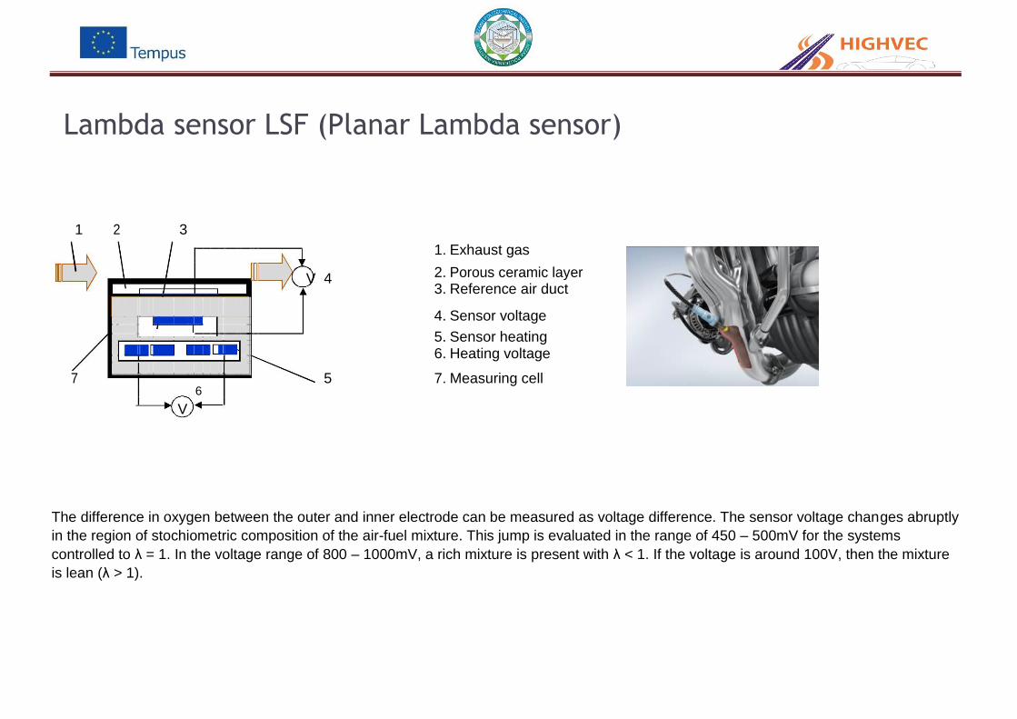
Lambda sensor LSF (Planar Lambda sensor)
1 2 3
1. Exhaust gas
V 4 2. Porous ceramic layer
3. Reference air duct
4. Sensor voltage
5. Sensor heating
7
6. Heating voltage
5 7. Measuring cell 6
V
The difference in oxygen between the outer and inner electrode can be measured as voltage difference. The sensor voltage changes abruptly
in the region of stochiometric composition of the air-fuel mixture. This jump is evaluated in the range of 450 – 500mV for the systems
controlled to λ = 1. In the voltage range of 800 – 1000mV, a rich mixture is present with λ < 1. If the voltage is around 100V, then the mixture
is lean (λ > 1).

Planar twin-port lambda sensor (LSF) - KTS 340 Diagnosis
MIL-lamp comes on
Error is stored
Information from the actual query:
The lambda sensor voltage does not change, measured
voltage value (449 mV) is the control unit backlash voltage. The
lambda control loop is open.
Lambda sensor voltage,
time profile (from the time
profile function of KTS 340)
Actual values query
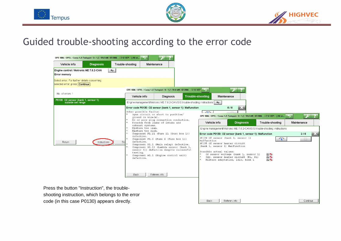
Guided trouble-shooting according to the error code
Press the button "Instruction", the trouble-
shooting instruction, which belongs to the error
code (in this case P0130) appears directly.

Guided trouble-shooting according to the error code
With the help of the multimeter function of KTS
340, the measured values can be displayed in
a window simultaneously. Red marking means
defect, green marking means OK.
When the display is green, but the value is
constant at 459 mV, it indicates the control unit
backlash voltage and thus not OK. When the
lambda sensor is functioning, the value must vary
around 459 mV depending on the mixture state
(rich/ lean).

Guided trouble-shooting according to the error code
Note:
Always follow the instructions precisely to avoid wrong measurements

After replacing lambda sensor
1
2
Erase error memory
Signal of the lambda sensor functioning properly (verification test)
1. Idling 2. Acceleration
Instrument cluster

Broadband Lambda-Sensor (LSU) – construction
1 2 3 4 5
- US ~ IP
1
+ U
P
URef
6 7 8 9 10
Schematic
1. Exhaust gas 2. Gas inlet hole 3. Porous diffusions barrier
(measuring chamber) 4. Reference cell with
reference air duct 5. Heater element 6. Porous protective coating 7. Oxygen pump cell with inner
and outer pump electrodes
8. Measuring chamber/
Diffusion slot 9. Nernst concentration cell 10. Control electronics
The exhaust gas reaches the measuring chamber / diffusion gap [8] of the Nernst-concentration cell [9] through the
small gas inlet hole [2]. The Nernst cell [9] compares the gas in the diffusion gap [8] to the ambient air in the
reference cell [4], so that the excess-air factor λ can be adjusted in the diffusion gap [8].

Broadband Lambda-Sensor (LSU) – function
Bosch
NGK (Typ: NTK)
1 2 3 4 5 mA
US ~ IP 1
Ip
1
-
UP
cu
rre
nt
Lean range
+
0
U
Ref
Pu
mp
-1
Rich range
-2 0,7 1 2 3 4
6
7 8 9 10
Air ratio λ
Diagram of the pump current Schematic design
By applying a pump voltage Up to the platinum electrodes of the pump cell, oxygen from the exhaust gas can be pumped in or pumped out of the diffusion gap through the diffusion barrier. Ionization of the Oxygen atoms takes place due to the addition of electrons to the Oxygen atoms at one of the electrodes. A symmetry is thus established, which now enables the flow of electrons in one direction. The target is an uniform λ=1 in the diffusion gap. The control electronic controls this to the voltage Up applied to the pump cell, using the Nernst concentration cell, so that the composition of gases in the diffusion gap remains constant at λ=1. In case of lean exhaust gas, the pump cell pumps the oxygen outwards (positive pump current). On the contrary, in case of rich exhaust gas, the oxygen (through catalytic decomposition of CO2 and H2O at the exhaust gas electrode) from the exhaust gas of the surrounding is pumped into the diffusion gap (negative pump current). At λ=1, no oxygen must be transported and the pump current is zero. The pump current is proportional to the oxygen concentration in the exhaust gas and therefore a (non-linear) measure for the air ratio λ. The residual oxygen in the exhaust gas will be determined through the pump time.

Testing broadband lambda sensor
Acceleration kick-in (rich)
Nernst voltage
Bosch
(Seat Toledo)
Pump voltage lean
rich
No acceleration (lean)
Heater voltage (PWM-signal
Signal inspection with oscilloscope

Broadband lambda sensor - Lambda sensor aging 1

Broadband lambda sensor - Lambda sensor aging 2
A contamination or aging of the lambda sensor affects the lambda sensor voltage or periodic time of the sensor signal
and hence has negative influence on the exhaust-gas emissions. The deviation of the lambda sensor characteristic curve
is monitored by a programmed value. The initial quantities of the lambda sensor master controller is monitored.

Speed sensor inductive
9 10 1. Cable
2. Permanent magnet
1 2 3 4 3. Sensorcase
4. Engine block
5. Soft iron core
11 6. Winding
7. Air gap
5 8. Sensor ring with
reference mark
6
9. Bezugsmarkensignal
8
7
10.Motordrehzahsignal
11.Amplitudenspannung
The inductive speed sensor is normally installed as a crankshaft sensor. It is mounted separated by an air gap opposite to the ferro-magnetic sensor ring. It contains a soft iron core which is surrounded by a winding . A magnetic feld extends over the pole pin up to the sensor ring. The magnetic flux depends on whether a tooth or a gap is present against the sensor. A tooth strengthens the magnetic flux, whereas a gap weakens it. The magnetic field changes induce varyingly large voltages which are visible in the signal. Using it, the engine RPM and position of the crankshaft, among others, can be determined.

Measurement of inductive sensors
Symbol of inductive Measurement by ESI SIS/CAS
sensors in ESI 2.0
Actual value
Possible faultcode

Speed sensor Hall
1
2
3
4
5 a
6
Z
7
φ L
U(V)
UA
L Z L
φs
High
Low
Drehwinkel φ
1. Electrical connections (plug)
2. Sensor housing
3. Engine housing
4. Sealing ring
5. Permanent magnet
6. Hall-IC
7. Sensor ring with teeth segments (Z) and gaps (L)
a air gap
φ rotational angle
Electrons of a voltage which is present on an element are deflected and thus a
Hall voltage is developed. This is prepared in the Hall-IC and sent to the ECU
as signal. The camshaft is set lower than the crankshaft by a ratio 1:2. Its position shows whether an engine piston which moves towards the TDC (top dead center) finds itself in the compression stroke or in the exhaust stroke. The camshaft sensor provides this information to the engine ECU.

Measurement of Hall sensors
V
Possible faultcode
Symbol of Hall-Sensors in ESI 2.0
Measurement by ESI SIS/CAS

Signal recording of the sensors
1 1. Signal of Hall sensors
(Camsaft)
2
2. Signal of inductive
sensors (Cranksaft)
3. Reference mark
signal
4. Engine speed signal
5. Amplitude voltage 6
3
4
The Hall sensor is not to be measured using an ohmmeter, as an ohmmeter would apply a voltage to the sensor and possibly
destroy the evaluation electronics.
An inductive pick-up emits a self-generated signal. This signal is normally applied to both signal wires. In this case, the signal wires can also be measured with respect to one another. In some cases however one wire is connected to ground. Failure to heed the polarity may then lead to measurement errors. When measured to ground, at least one signal wire must always emit a signal.