joint polar satellite system-2 (jpss-2) satellite high ... · jpss-2 satellite hrd to dbs rf icd...
TRANSCRIPT
Effective Date: December 10, 2018
Expiration Date: December 10, 2023
472-00340, Rev B
Joint Polar Satellite System (JPSS) Flight Project
Code 472
Joint Polar Satellite System-2 (JPSS-2)
Satellite High-Rate Data (HRD) to
Direct Broadcast Stations (DBS)
Radio Frequency (RF)
Interface Control Document (ICD)
Applies Also to
JPSS-3 and JPSS-4
For Public Release
Goddard Space Flight Center Greenbelt, Maryland
GSFC JPSS CMO
12/10/2018
Released

JPSS-2 Satellite HRD to DBS RF ICD 472-00340, Rev B
Effective Date: December 10, 2018
i
JPSS-2 Satellite High-Rate Data (HRD) to
Direct Broadcast Stations (DBS) Radio Frequency (RF)
Interface Control Document (ICD)
JPSS Signature Approval Page
Prepared By:
Jirasak Visalsawat
Concurred By:
Jeanine Murphy-Morris
J2 Observatory Manager, NASA GSFC
Daren Iverson
J2 Spacecraft, Northrup Grumman Innovation Systems
Approved By:
Jean Grady
Deputy Project Manager, NASA GSFC
Electronic Approval available on-line at: https://jpssmis.gsfc.nasa.gov
Goddard Space Flight Center
Greenbelt, Maryland
JPSS-2 Satellite HRD to DBS RF ICD 472-00340, Rev B
Effective Date: December 10, 2018
ii
Preface
This document is under JPSS Flight Project configuration control. Once this document is
approved, JPSS Flight Project approved changes are handled in accordance with Class I and
Class II change control requirements as described in the JPSS Configuration Management
Procedures, and changes to this document shall be made by complete revision.
Any questions should be addressed to:
JPSS Configuration Management Office
NASA/GSFC
Code 472
Greenbelt, MD 20771
JPSS-2 Satellite HRD to DBS RF ICD 472-00340, Rev B
Effective Date: December 10, 2018
iii
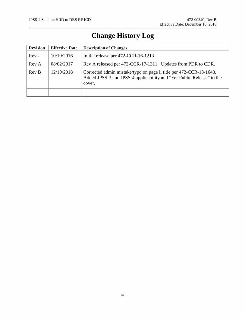
Change History Log Revision Effective Date Description of Changes
Rev - 10/19/2016 Initial release per 472-CCR-16-1213
Rev A 08/02/2017 Rev A released per 472-CCR-17-1311. Updates from PDR to CDR.
Rev B 12/10/2018 Corrected admin mistake/typo on page ii title per 472-CCR-18-1643.
Added JPSS-3 and JPSS-4 applicability and “For Public Release” to the
cover.

6470-ICD23510, Rev A
JOINT POLAR SATELLITE SYSTEM (JPSS)
SATELLITE HIGH-RATE DATA TO DIRECT BROADCAST STATIONS RADIO FREQUENCY (RF)
INTERFACE CONTROL DOCUMENT (ICD)
CONTRACT NO. NNG10AZ13B D.O. NNG15VE05D
CDRL SE-12e
Date: August 01, 2017
Prepared by ORBITAL ATK
Space Systems Group (SSG) – Gilbert 100 South McQueen Road
Gilbert, Arizona 85233
CAGE Code: 5YY58
PREPARED BY: SYSTEMS ENGINEER LANCE MCCREARY APPROVED BY: SPACECRAFT SYSTEMS ENGINEER TONY ALTOSINO LEAD SYSTEMS ENGINEER ERIC ORRILL PROGRAM CHIEF ENGINEER JOHN JORDAN
FLIGHT ASSURANCE MANAGER WERNER BRUCKNER PROGRAM MANAGER DAREN IVERSON RELEASED BY: CONFIGURATION/DATA MANAGEMENT KATHIE BALL
6470-ICD23510, Rev A
Page i
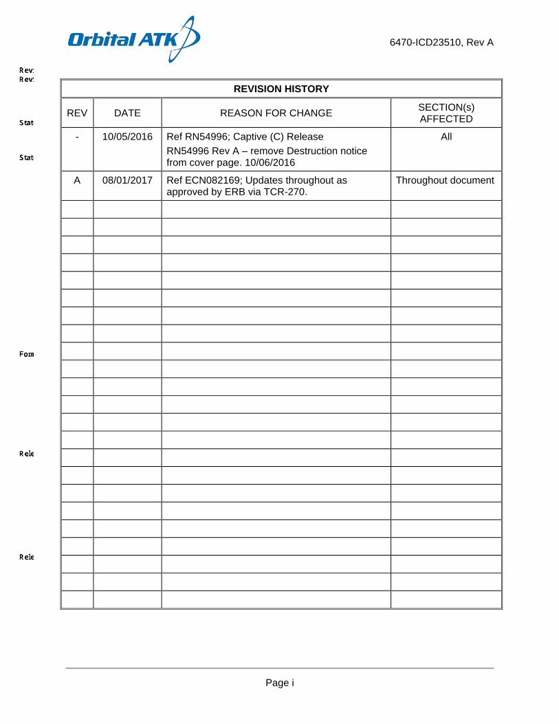
REVISION HISTORY
REV DATE REASON FOR CHANGE SECTION(s) AFFECTED
- 10/05/2016 Ref RN54996; Captive (C) Release RN54996 Rev A – remove Destruction notice from cover page. 10/06/2016
All
A 08/01/2017 Ref ECN082169; Updates throughout as approved by ERB via TCR-270.
Throughout document

6470-ICD23510, Rev A
Page ii
TABLE OF CONTENTS
PAGE
1 INTRODUCTION ..................................................................................................................... 1 1.1 Purpose ............................................................................................................................. 1 1.2 Scope ................................................................................................................................ 1 1.3 Document Compliance ...................................................................................................... 1
2 APPLICABLE AND REFERENCE DOCUMENTS .................................................................. 3 2.1 Applicable Documents ...................................................................................................... 3
2.1.1 Orbital ATK Space Systems Group Documents ........................................................ 3 2.1.2 Government Documents ............................................................................................ 3 2.1.3 Non-Government Standards ...................................................................................... 3
2.2 Reference Documents ...................................................................................................... 4 2.2.1 Orbital ATK Space Systems Group Documents ........................................................ 4 2.2.2 Consultative Committee for Space Data Systems (CCSDS) Documents .................. 4
3 DEFINITIONS ......................................................................................................................... 5 4 INTERFACE DESCRIPTION .................................................................................................. 6
4.1 General ............................................................................................................................. 6 4.2 S-band TT&C .................................................................................................................... 8 4.3 Stored Mission Data (SMD) Element (Ka-Band Subsystem) ............................................ 8 4.4 High Rate Data (HRD) Element (X-Band Subsystem) ...................................................... 8
4.4.1 HRD Operations Modes ............................................................................................. 8 4.4.2 HRD Operational Constraints .................................................................................... 9 4.4.3 HRD Key Component Descriptions ............................................................................ 9 4.4.4 HRD Ground Power Flux Density ............................................................................ 11 4.4.5 HRD Link Budget Analysis ....................................................................................... 12
5 COMMUNICATIONS INTERFACE REQUIREMENTS ......................................................... 16 5.1 JPSS Polar Ground Station Requirements ..................................................................... 16
5.1.1 SvalSat ..................................................................................................................... 16 5.1.2 McMurdo .................................................................................................................. 16 5.1.3 FCDAS ..................................................................................................................... 16 5.1.4 TrollSat ..................................................................................................................... 16 5.1.5 White Sands Complex (WSC) .................................................................................. 16 5.1.6 Direct Broadcast Ground Station ............................................................................. 16
5.2 Ground Test Interface Requirements .............................................................................. 16 5.2.1 RF Compatibility Testing .......................................................................................... 16 5.2.2 JPSS Compatibility Test (JCT) Rack ....................................................................... 16 5.2.3 External Network Interface (JPSS WAN to JCT Rack) ............................................ 17
5.3 RF Spectral Requirements .............................................................................................. 17 6 COMMANDS ......................................................................................................................... 17

6470-ICD23510, Rev A
Page iii
TABLE OF CONTENTS (CONTINUED)
PAGE
7 TELEMETRY AND MISSION DATA ..................................................................................... 17 7.1 Downlink/Return Link Data Common to Multiple Links ................................................... 17
7.1.1 General .................................................................................................................... 17 7.1.2 Space Packets ......................................................................................................... 17 7.1.3 Transfer Frame ........................................................................................................ 24 7.1.4 Randomization, Coding and Frame Synchronization ............................................... 30 7.1.5 Modulation ............................................................................................................... 30 7.1.6 Radio Frequency Characteristics ............................................................................. 30
7.2 S-band Telemetry (TT&C) ............................................................................................... 30 7.3 Ka-Band Downlink (SMD) ............................................................................................... 30 7.4 X-Band Telemetry (HRD) ................................................................................................ 30
7.4.1 General .................................................................................................................... 30 7.4.2 Space Packets ......................................................................................................... 32 7.4.3 Transfer Frame ........................................................................................................ 32 7.4.4 Randomization, Coding and Frame Synchronization ............................................... 34 7.4.5 Modulation ............................................................................................................... 38 7.4.6 Radio Frequency Characteristics ............................................................................. 40
8 OPERATIONS ....................................................................................................................... 41 8.1 Operating Modes and Command Events ........................................................................ 41
8.1.1 Launch, Early Orbit, and Anomaly (LEO&A) ............................................................ 41 8.1.2 Routine Operations .................................................................................................. 42 8.1.3 Contingency Operations .......................................................................................... 42
8.2 Approach for Maneuver Planning and Execution ............................................................ 43 8.2.1 S-Band Operations .................................................................................................. 43 8.2.2 X-Band Operations .................................................................................................. 43
LIST OF TABLES
Table SC-GND-4480. CDRL SE12e Compliance Table ............................................................. 1 Table SC-GND-776. CCSDS Reference Table .......................................................................... 4 Table SC-GND-8106. JPSS RF Link Characteristics: X-Band (HRD) Downlink ......................... 7 Table SC-GND-4533. HRD PFD Parameters .......................................................................... 11 Table SC-GND-4536. HRD Link Parameters ........................................................................... 12 Table SC-GND-4415. APID Range Assignments .................................................................... 20 Table SC-GND-4672. Spacecraft VCID and Downlink Assignments ....................................... 32 Table SC-GND-4348. HRD Ground Station Minimum G/T ...................................................... 40 Table SC-GND-3279. HRD (X-Band) Maximum Power Flux Density Levels ............................ 41 Table Verification Cross Reference Matrix (VCRM) ................................................................ A-2
6470-ICD23510, Rev A
Page iv
LIST OF FIGURES
PAGE
Figure SC-GND-92. SC to Ground System RF Links ................................................................. 7 Figure SC-GND-633. HRD (X-Band) Element Functional Diagram ............................................ 8 Figure SC-GND-4521. HRD CADU Block Structure.................................................................... 9 Figure SC-GND-4528. HRD Transmitter Function Block Diagram ............................................ 10 Figure SC-GND-4525. HRD Antenna Pattern ........................................................................... 11 Figure SC-GND-4678. X-Band (HRD) PFD Plot ....................................................................... 12 Figure SC-GND-3318. HRD Detailed Link Calculation.............................................................. 15 Figure SC-GND-1124. Space Packet Structural Components: Non-Segmented Packets ........ 18 Figure SC-GND-8008. Space Packet Structural Components: First Segment of Segmented
Packets ........................................................................................................................... 18 Figure SC-GND-3916. Space Packet Structural Components: Middle and Last Segments of
Segmented Packets ........................................................................................................ 18 Figure SC-GND-1129. Packet Primary Header .......................................................................... 19 Figure SC-GND-1180. Packet Secondary Header: Non-Segmented Packets ........................... 22 Figure SC-GND-4081. Packet Secondary Header: First Segment of Segmented Packets ...... 22 Figure SC-GND-3970. CCSDS Day Segmented Time Format ................................................. 23 Figure SC-GND-641. AOS Transfer Frame Structural Components ......................................... 25 Figure SC-GND-645. Transfer Frame Primary Header ............................................................. 26 Figure SC-GND-719. Multiplexing Protocol Data Unit (M_PDU) ................................................ 29 Figure SC-GND-4594. X-Band (HRD) Software Downlink Frames ........................................... 31 Figure SC-GND-4226. Reed-Solomon Codeblock Partitioning ................................................. 34 Figure SC-GND-4249. Pseudo-Randomizer Logic Diagram ..................................................... 36 Figure SC-GND-4263. RS Encoded Transfer Frame ASM Bit Pattern ..................................... 37 Figure SC-GND-4268. Basic Convolutional Encoder Block Diagram ........................................ 38 Figure SC-GND-4188. Satellite Modes and Transitions ............................................................ 41
LIST OF APPENDICES
APPENDIX A. VERIFICATION CROSS REFERENCE MATRIX (VCRM) .............................. A-1 APPENDIX B. TBX MATRIX ................................................................................................... B-1
6470-ICD23510, Rev A
Page v
LIST OF ACRONYMS ACS Attitude Control System AES Advanced Encryption Standard AOS Advanced Orbiting Systems APA Antenna Pointing Assembling APID Application Process Identifier ASF Alaskan Satellite Facility ASM Attached Sync Marker ATMS Advanced Technology Microwave Sounder ATS Absolute Time Sequence BC Bus Controller BCH Bose-Chaudhuri-Hocquenghem BER bit error rate BPSK Binary Phase Shift Keying BTG Bit Transition Generator C Packet Data Length Count C&DH Command & Data Handling C&T Command & Telemetry C3S Command, Control, and Communication Segment CADU Channel Access Data Unit CBC Cipher Block Chaining CC Convolutional Code CCM Counter with Cipher Block Chaining – Message Authentication Code CCSDS Consultative Committee for Space Data Systems CDH Command Data Handling CDRL Contract Data Requirements List CDS CCSDS Day Segmented CGS Common Ground System CLCW Command Link Control Word Clk Clock CLTU Command Link Transmission Unit CMD Command CMM Carrier Modulation Mode COP Command Operation Procedure CPL Circular Polarization Filter CSM Code Sync Marker CUC CCSDS Unsegmented Time Code DBS Direct Broadcast Stations

6470-ICD23510, Rev A
Page vi
LIST OF ACRONYMS DG2 Data Group 2 DSN Deep Space Network EGSE Electronic Ground Support Equipment EIRP Equivalent Isotropically Radiated Power EOL End Of Life EPC Electronic Power Conditioner EPS Electronic Power Subsystems EU Electronic Unit FARM Frame Acceptance and Reporting Mechanism FDU Frame Data Unit FEC Forward Error Correction FMC Flash Memory Card FOP Frame Operation Procedure FOT Flight Operations Team FSW Flight Software G/T Gain to Noise Temperature Ratio GN Ground Network GNC Guidance Navigation Control GND Ground GO Ground Operations GPS Global Positioning System GS Ground Station GSE Ground Support Equipment GSFC Goddard Space Flight Center HK House keeping HR High Rate HRD High Rate Data HRDFEP High Rate Demodulator & Front End Processor HRTG High Rate Test Generator I&T Integration & Testing ICD Interface Control Document ID Identification IEM Integrated Electronics Module IF Intermediate Frequency ITOS Integration and Test Operations System ITU International Telecommunication Union JCT JPSS Compatibility Test

6470-ICD23510, Rev A
Page vii
LIST OF ACRONYMS k 1000 (not 1024)/constraint-length LAN Local Area Network LDPC Low Density Parity Check LEO&A Launch, Early, Orbit, and Activation LNA Low Noise Amplifier LSB Least Significant Byte/Bit M_PDU Multiplexing Protocol Data Unit MAC Message Authentication Code MAP Multiplexer Access Point MCID Master Channel Identifier MGS McMurdo Ground Station MSB Most Significant Byte/Bit NASA National Aeronautics and Space Administration NEN Near Earth Network NIST National Institute of Standards and Technology NOAA National Oceanic and Atmospheric Administration NRZ Non-Return to Zero NRZ-L Non-Return Zero Level NRZ-M Non-Return Zero Mark NSOF NOAA Satellite Operations Facility NTIA National Telecommunications and Information Administration OBO Output Backoff OCF Operational Control Field OMPS Ozone Mapping Profiler Suite OP Operation OQPSK Offset Quadrature Phase Shift Keying PCM Pulse Code Modulation PFD Power Flux-Density PGS Polar Ground Station PIE Payload Interface Electronics PLOP Physical Layer Operations Procedures PN Pseudo random Noise Prec/No. Received Power to noise spectral density ratio PSD Power Spectral Density QPSK Quadrature Phase Shift Keying r Rate RBI Radiation Budget Instrument

6470-ICD23510, Rev A
Page viii
LIST OF ACRONYMS RF Radio Frequency RHCP Right Hand Circular Polarization RS Radiated Susceptibility RSVD Remote Shared Virtual Disk RTS Relative Time Sequence S/C Spacecraft SADA Solar Array Drive Assembly SAF Single Access Forward SAR Single Access Return SC Spacecraft SCID Spacecraft ID SEC Single Error Correction SEL Single Event Latchup SFCG Space Frequency Coordination Group SGE SMD Ground Equipment SGS Svalbard Ground Station SHK Stored Housekeeping SKMP System Key Management Plan SMD Stored Mission Data SN Space Network SNIP Space Network Interoperable PN Code Libraries SNUG Space Network's User Guide SOH State of Health SPS Symbols Per Second SQPN Staggered Quaternary Pseudo-Noise SQPSK Staggered QPSK SRD System Requirements Document SRRC Square Root Raised Cosine SSA S-Band Single Access SSG Space Systems Group SSOH Stored Satellite State of Health SSR Solid State Recorder T&C Telemetry and Command TBD To Be Determined TBR To Be Reviewed TC Telecommands TDRSS Tracking Data And Relay Satellite System

6470-ICD23510, Rev A
Page ix
LIST OF ACRONYMS TGE T&C Ground Equipment TIA/EIA Telecommunications Industry Association/Electronic Industries Alliance TLM Telemetry TM Technical Manual TOD Time of Day TT&C Telemetry, Tracking, and Command TWT Traveling Wave Tube TX/RX Transmit/Receive UDL Uplink/Downlink UQPSK Unbalanced QPSK UTC Coordinate Universal Time VC Virtual Channel VCDU Virtual Channel Data Unit VCID Virtual Channel Identifier VIIRS Visible Infrared Imaging Radiometer Suite WAN Wide Area Network WGS Wallops Ground Station WSC White Sands Complex

6470-ICD23510, Rev A
Page 1 of 43
1 INTRODUCTION
1.1 Purpose This Satellite High Rate Data (HRD) to Direct Broadcast Stations (DBS) RF ICD is intended to satisfy the requirements of CDRL SE-12e.
This Interface Control Document (ICD) specifies the X-band High Rate Data (HRD) to Direct Broadcast Stations (DBS) interface. Section 1.2 further explains the content of this document.
1.2 Scope This ICD includes the following content:
a. Data formats, communications protocols, and data rates (Section 7) b. Compression algorithms (if any) and error detection and correction schemes (Section 7) c. Antenna patterns, EIRP, G/T, beam width, downlink, frequencies, polarizations, and
modulations for each channel (Section 4) d. Telemetry formats (Section 7) e. Satellite contact scenarios for data transmission, operations, and maintenance (Section
8) f. Link analysis for available ground station antennas (Section 4) g. Interface requirements for RF compatibility test (not applicable) h. Interface requirements for end-to-end test (Section 5) i. Description of data time tagging (Section 7) j. Description of Spacecraft operating modes and command events (Section 8) k. Approach for maneuver planning and execution (Section 8)
NOTE: The HRD RF ICD shall only contain information for public distribution.
For additional information regarding the JPSS Concept of Operations, refer to the JPSS Spacecraft Concept of Operations (6470-DG31100) [CDRL OPS-7].
1.3 Document Compliance This document is intended to meet the criteria of SE-12e in the JPSS-2 Contract Data Requirements List (CDRL), Attachment D. Table SC-GND-4480 contains the compliance matrix showing the Data Item Description (DID) section, Preparation Information, and the section(s) where the information is located in this document.
Table SC-GND-4480. CDRL SE12e Compliance Table
Document Link HRD to GS RF ICD (12e) Section Command Telemetry
a Data formats N/A 7.1, 7.4
SC-GND-7502, 7520 Communications protocols N/A 2.2.2
SC-GND-776

6470-ICD23510, Rev A
Page 2 of 43
Table SC-GND-4480. CDRL SE12e Compliance Table
Document Link HRD to GS RF ICD (12e) Section Command Telemetry
Data rates N/A 7.1.6, 7.4.6 SC-GND-7509, 7526
Encryption/decryption formats N/A N/A b Compression algorithms N/A N/A Error detection and correction schemes N/A 7.1.4, 7.4.4
SC-GND-7507, 4220 c Antenna patterns N/A 4.4.3.2
SC-GND-4525 EIRP N/A N/A G/T N/A 4.4, 5.1, 7.4.5.8
SC-GND-4331, 3131, 3222, 3136, 4347, 4348
Beam width N/A 7.1.6, 7.4.6.1 SC-GND-105, 4524, 4636
Uplink frequencies N/A N/A Uplink polarizations N/A N/A Uplink modulations N/A N/A Downlink frequencies N/A 7.4.5.1, 7.4.6.1
SC-GND-4275, 3638 Downlink polarizations N/A 7.1.6.1
SC-GND-4597 Downlink modulations N/A 7.4.6.1
SC-GND-597 d Telemetry formats N/A 7.1, 7.4
SC-GND-7502, 7520 Command formats N/A N/A e Satellite contact scenarios for data transmission, operations, and maintenance
N/A 8 SC-GND-4178
f Link analysis for available ground station antennas
N/A 4.4.5 SC-GND-3318
g Interface requirements for RF compatibility test
N/A N/A

6470-ICD23510, Rev A
Page 3 of 43
Table SC-GND-4480. CDRL SE12e Compliance Table
Document Link HRD to GS RF ICD (12e) Section Command Telemetry
h Interface requirements for end-to-end test
N/A N/A
i Description of command time tagging N/A 8
SC-GND-4178 Description of data time tagging j N/A 8
SC-GND-4178 Description of spacecraft operating modes and command events
N/A 7.1, 7.4SC-GND-7502, 7520
k N/A 2.2.2 SC-GND-776
Approach for maneuver planning and execution
N/A 7.1.6, 7.4.6 SC-GND-7509, 7526
2 APPLICABLE AND REFERENCE DOCUMENTS
2.1 Applicable Documents Unless otherwise specified, the following documents in their current issue form a part of this document to the extent specified herein.
2.1.1 Orbital ATK Space Systems Group Documents None
2.1.2 Government Documents a. 450-SNUG Space Network Users' Guide (SNUG) Revision 10, Effective Date
August 3rd, 2012 b. GSFC 472-00280 JPSS-2 Satellite Requirements Document c. GSFC 472-00244 JPSS Data Formats Requirement Document d. JPSS-2/3/4 PN Code Description, received on 25 January 2017 e. GSFC 472-00718 System Key Management Plan (SKMP) for the JPSS-2, 3, and 4
Missions
2.1.3 Non-Government Standards a. CCSDS 131.0-B-2 Recommendation, TM Synchronization and Channel Coding
August 2011. b. CCSDS 133.0-B-1 Recommendations for Space Packet Protocol. Issue 1, September
2003 c. CCSDS 133.1-B-1 Encapsulation Service. Issue 1. June 2006
6470-ICD23510, Rev A
Page 4 of 43
d. CCSDS 231.0-B-2 Recommendation, TC Synchronization and Channel Coding. Issue 2. September 2010.
e. CCSDS 232.0-B-3 Recommendation, TC Space Data Link Protocol. Issue 3. September 2015.
f. CCSDS 232.1-B-2 Recommendation, Communication Operation Procedure-1. Issue 2. September 2010
g. CCSDS 401.0-B-25 Recommendation for Radio Frequency and Modulation Systems. Issue 25. February 2015
h. CCSDS 732.0-B-3 Recommendations for Advanced Orbiting Systems - Space Data Link Protocol. Issue 3. September 2015.
i. ITU-R SA 1157 Protection Criteria for Deep-Space Research j. ITU-R P.618-12 Propagation data and prediction methods required for the design
of Earth-space telecommunication systems k. NIST FIPS Pub 197 Federal Information Processing Standards Publication 197
November 26, 2001 Announcing the Advanced Encryption Standard (AES)
l. NIST SP 800-38C Recommendation for Block Cipher Modes of Operation: The Counter with Cipher Block Chaining- Message Authentication Code (CCM) Mode for Authentication and Confidentiality
m. NTIA Manual Manual of Regulations and Procedures for Federal Radio Frequency Management, September 2015 Revision of the May 2013 Edition
2.2 Reference Documents The documents listed contain useful facts or are recommended for additional information.
2.2.1 Orbital ATK Space Systems Group Documents a. 6470-ML31100 Rev - C&T Handbook [CDRL OPS-2] b. 6470-DG31100 JPSS Spacecraft Concept of Operations [CDRL OPS-7] c. 6470-AR45100 JPSS Communications Subsystem Performance Analysis [CDRL
SE-3k] d. 6470-PF23200 Satellite Performance Specification (SPS) [CDRL SE-1]
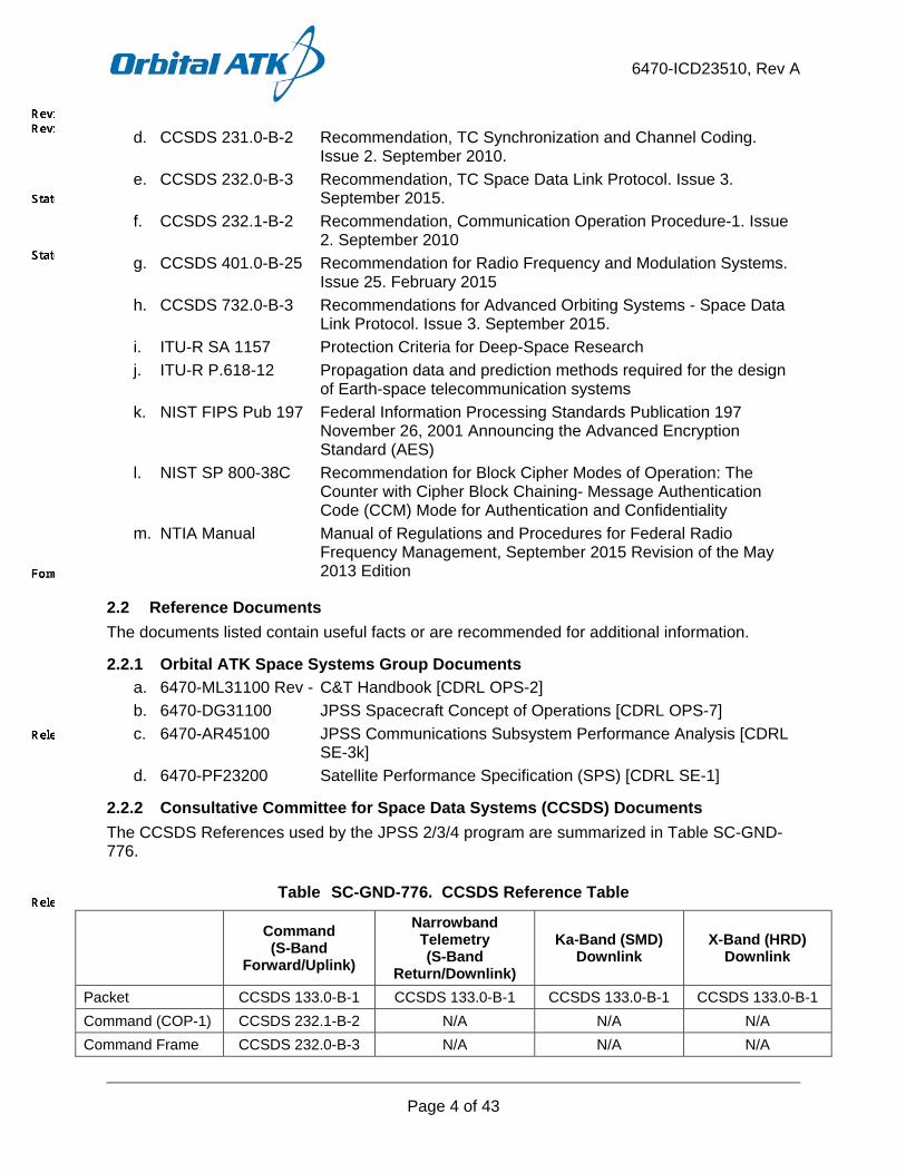
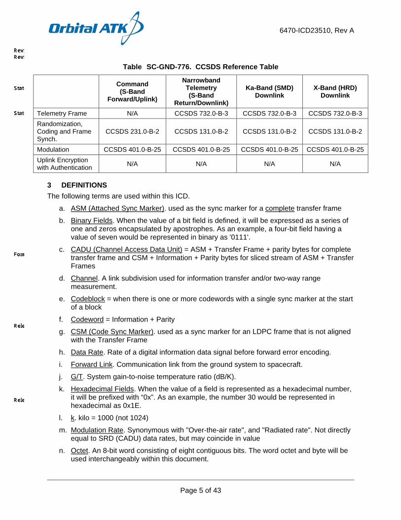
2.2.2 Consultative Committee for Space Data Systems (CCSDS) Documents The CCSDS References used by the JPSS 2/3/4 program are summarized in Table SC-GND-776.
Table SC-GND-776. CCSDS Reference Table
Command (S-Band
Forward/Uplink)
Narrowband Telemetry (S-Band
Return/Downlink)
Ka-Band (SMD) Downlink
X-Band (HRD) Downlink
Packet CCSDS 133.0-B-1 CCSDS 133.0-B-1 CCSDS 133.0-B-1 CCSDS 133.0-B-1 Command (COP-1) CCSDS 232.1-B-2 N/A N/A N/A Command Frame CCSDS 232.0-B-3 N/A N/A N/A
6470-ICD23510, Rev A
Page 5 of 43
Table SC-GND-776. CCSDS Reference Table
Command (S-Band
Forward/Uplink)
Narrowband Telemetry (S-Band
Return/Downlink)
Ka-Band (SMD) Downlink
X-Band (HRD) Downlink
Telemetry Frame N/A CCSDS 732.0-B-3 CCSDS 732.0-B-3 CCSDS 732.0-B-3 Randomization, Coding and Frame Synch.
CCSDS 231.0-B-2 CCSDS 131.0-B-2 CCSDS 131.0-B-2 CCSDS 131.0-B-2
Modulation CCSDS 401.0-B-25 CCSDS 401.0-B-25 CCSDS 401.0-B-25 CCSDS 401.0-B-25 Uplink Encryption with Authentication N/A N/A N/A N/A
3 DEFINITIONS The following terms are used within this ICD.
a. ASM (Attached Sync Marker). used as the sync marker for a complete transfer frame
b. Binary Fields. When the value of a bit field is defined, it will be expressed as a series of one and zeros encapsulated by apostrophes. As an example, a four-bit field having a value of seven would be represented in binary as '0111'.
c. CADU (Channel Access Data Unit) = ASM + Transfer Frame + parity bytes for complete transfer frame and CSM + Information + Parity bytes for sliced stream of ASM + Transfer Frames
d. Channel. A link subdivision used for information transfer and/or two-way range measurement.
e. Codeblock = when there is one or more codewords with a single sync marker at the start of a block
f. Codeword = Information + Parity
g. CSM (Code Sync Marker). used as a sync marker for an LDPC frame that is not aligned with the Transfer Frame
h. Data Rate. Rate of a digital information data signal before forward error encoding.
i. Forward Link. Communication link from the ground system to spacecraft.
j. G/T. System gain-to-noise temperature ratio (dB/K).
k. Hexadecimal Fields. When the value of a field is represented as a hexadecimal number, it will be prefixed with “0x”. As an example, the number 30 would be represented in hexadecimal as 0x1E.
l. k. kilo = 1000 (not 1024)
m. Modulation Rate. Synonymous with "Over-the-air rate", and "Radiated rate". Not directly equal to SRD (CADU) data rates, but may coincide in value
n. Octet. An 8-bit word consisting of eight contiguous bits. The word octet and byte will be used interchangeably within this document.
6470-ICD23510, Rev A
Page 6 of 43
o. OQPSK. Offset Quadrature Phase Shift Keying is synonymous with Staggered Quadrature Phase Shift Keying (SQPSK)
p. Physical Channel. A stream of bits transferred over a space link in a single direction.
q. PREC/NO. Received power to noise spectral density ratio.
r. Return Link. Communication link from spacecraft to the ground system.
s. Serial data. Data of similar kind occurring one after another.
t. SQPN (Staggered Quadrature Pseudo-random Noise). SQPSK signal spread by spreading code
u. SQPSK. Staggered Quadrature Phase Shift Keying is synonymous with Offset Quadrature Phase Shift Keying (OQPSK)
v. Symbol Rate. Rate of the digital information data signal after forward error correction encoding and other overhead bits are attached. Bit symbol rate (sps): once info bits are RS or LDPC-encoded. Modulation symbol rate (Sps), also called baud rate, is the data rate (code sps) divided by M (msps = sps/M) once bit-symbol stream is modulated onto M-order PSK signal.
w. TC. A generic term used to describe command data during the time that they are being telecommunicated to the Observatory.
x. Type A or B (COP-1). As defined in CCSDS 232.0-B-3, the Frame Acceptance and Reporting Mechanism (FARM) associated with the COP can be made to operate in a normal “Acceptance” (frame “Type-A”) mode or a “Bypass” (frame “Type-B”) mode, according to the setting of the BYPASS FLAG.
y. Type C or D (COP-1). As defined in CCSDS 232.0-B-3, the CONTROL COMMAND FLAG specifies whether the data field of the TC Transfer Frame is conveying transfer “Control Commands” (the “C” mode), or “Data” (the “D” mode)
z. Virtual Channel. An identifier that permits all Transfer Frames that are members of a given sequence to be uniquely identified. It permits multiple user data types to be multiplexed together so that they may share the finite capacity of the single physical space data channel.
aa. Virtual Channel Data Unit (VCDU). This term is synonymous with Transfer Frame
4 INTERFACE DESCRIPTION
4.1 General This section describes the functional design of the Ground System and Spacecraft RF links. Major link parameters and characteristics are specified below and shown in Figure SC-GND-92.
The SC RF Communications Subsystem features three specific elements:
a. An S-Band Narrowband element for low rate TT&C communications. b. A High Rate Data (HRD) X-Band element for continuous mission data transmission. c. A Stored Mission Data (SMD) Ka-band element for scheduled mission data
transmission.

6470-ICD23510, Rev A
Page 7 of 43
Redundant components are used throughout the Communication Subsystem providing high reliability and single fault tolerance. Components are cross-strapped to the Command and Data Handling (C&DH) Subsystem to enhance reliability.
The JPSS 2/3/4 RF Interfaces, as shown in Figure SC-GND-92, are as follows:
a. Ground System to Spacecraft S-Band Uplink b. Space Network to Spacecraft S-Band SAF c. Spacecraft to Ground System S-Band Downlink d. Spacecraft to Space Network S-Band SAR e. Spacecraft to Ground System Ka-Band SMD Downlink f. Spacecraft to Space Network Ka-Band SAR g. Spacecraft to DBS X-Band HRD Downlink
Figure SC-GND-92. SC to Ground System RF Links
JPSS RF link characteristics are summarized for the X-Band downlink in Table SC-GND-8106.
Table SC-GND-8106. JPSS RF Link Characteristics: X-Band (HRD) Downlink
Data Flow
Center Frequency Rate
Coverage (half cone
angle) BER PCM
Format Block
Coding Convolutional
Coding Modulation Polarization
HRD 7812 MHz 25
Msps (CADU)
62° about +Z S/C
axis 10-8 NRZ-M (255,223)
RS, I=5 Rate ½ length
7 OQPSK RHCP
SC-GND-3638
SC-GND-4634
SC-GND-4636
SC-GND-4637
SC-GND-4638
SC-GND-4639 SC-GND-4640 SC-GND-
597, 4286 SC-GND-
4597
6470-ICD23510, Rev A
Page 8 of 43
4.2 S-band TT&C This section is not applicable to the Satellite HRD to Direct Broadcast Stations (DBS) RF ICD.
4.3 Stored Mission Data (SMD) Element (Ka-Band Subsystem) This section is not applicable to the Satellite HRD to DBS RF ICD.
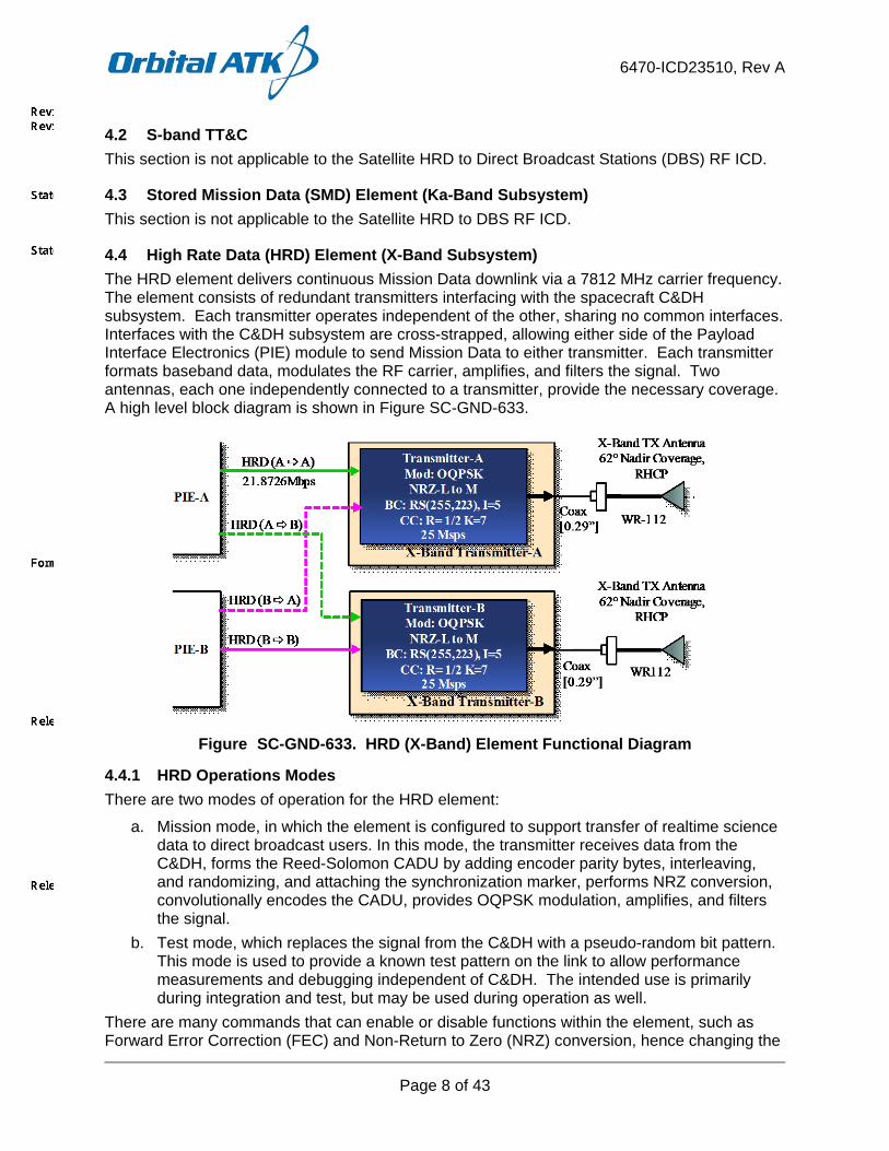
4.4 High Rate Data (HRD) Element (X-Band Subsystem) The HRD element delivers continuous Mission Data downlink via a 7812 MHz carrier frequency. The element consists of redundant transmitters interfacing with the spacecraft C&DH subsystem. Each transmitter operates independent of the other, sharing no common interfaces. Interfaces with the C&DH subsystem are cross-strapped, allowing either side of the Payload Interface Electronics (PIE) module to send Mission Data to either transmitter. Each transmitter formats baseband data, modulates the RF carrier, amplifies, and filters the signal. Two antennas, each one independently connected to a transmitter, provide the necessary coverage. A high level block diagram is shown in Figure SC-GND-633.
Figure SC-GND-633. HRD (X-Band) Element Functional Diagram
4.4.1 HRD Operations Modes There are two modes of operation for the HRD element:
a. Mission mode, in which the element is configured to support transfer of realtime science data to direct broadcast users. In this mode, the transmitter receives data from the C&DH, forms the Reed-Solomon CADU by adding encoder parity bytes, interleaving, and randomizing, and attaching the synchronization marker, performs NRZ conversion, convolutionally encodes the CADU, provides OQPSK modulation, amplifies, and filters the signal.
b. Test mode, which replaces the signal from the C&DH with a pseudo-random bit pattern. This mode is used to provide a known test pattern on the link to allow performance measurements and debugging independent of C&DH. The intended use is primarily during integration and test, but may be used during operation as well.
There are many commands that can enable or disable functions within the element, such as Forward Error Correction (FEC) and Non-Return to Zero (NRZ) conversion, hence changing the

6470-ICD23510, Rev A
Page 9 of 43
configuration. However, these are in-place as test and debug aids and are not designated operational modes.
4.4.2 HRD Operational Constraints The element design supports a 100% duty cycle.
The operation of the element is controlled from the flight software and the Payload Interface Electronics (PIE).
4.4.3 HRD Key Component Descriptions
4.4.3.1 HRD Transmitter Overview The HRD transmitter provides High Rate Data baseband and RF processing for transmission to ground elements.
The transmitter sources a clock to the C&DH subsystem and receives a 8-bit parallel data signal which is flow-controlled using the Ready and Valid signals between the transmitter and the C&DH as described above. Within the transmitter, each C&DH transfer frame is located by isolating a 32 bit Attached Synchronization Marker (ASM). Once the frame is isolated, the transmitter collects a block of 1115 bytes and calculates the 160 byte Reed-Solomon parity data and then interleaves the block to a depth of 5. The systematic input bytes and the parity bytes are randomized and the attached synchronization marker prepended to each block forming the Channel Access Data Unit (CADU). The entire process conforms to CCSDS 131.0-B-2. Figure SC-GND-4521 shows the structure of the C&DH transfer frame, the Virtual Channel Data Unit (VCDU) (input to Reed-Solomon process), and the resulting CADU.
ASM4 Bytes
Information1115 Bytes
R-S Parity160 Bytes
VCDU
CADU (1279 Bytes)
C&DH Transfer Frame
Figure SC-GND-4521. HRD CADU Block Structure
Following the Reed-Solomon process, the signal is NRZ encoded. The NRZ-L signal is encoded using mark inversion format, forming NRZ-M. This process allows the ground receiver to resolve the phase ambiguity inherent with phase shift keyed modulation at a small penalty (~0.2 dB at BER = 10^-8) in required Eb/No.
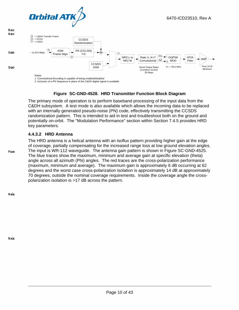
After the NRZ encoding the signal is convolutionally encoded, providing additional error performance improvement. A rate ½, constraint length 7 code is used consistent with CCSDS 131.0-B-2. The two outputs of the convolutional encoder (G1 and G2-Invert) provide the Offset Quadrature Phase Shift Keying (OQPSK) of the 7812 MHz RF carrier. The RF signal is amplified to a 10 Watt end-of life power level and filtered consistent with the NTIA mask requirements. A functional diagram of this processing within the HRD transmitter is shown in Figure SC-GND-4528.
6470-ICD23510, Rev A
Page 10 of 43
RS (223,255) I=5
CCSDSRandomization
CCSDSASM
NRZ-L to NRZ-M
Rate ½, K=7Convolutional AMP
G1
G2
Fc = 7812 MHz Pout 10 W Minimum
NTIAFilter
Serial Output Rates (Combine G1/G2)
50 Msps
~ 21.873 Mbps
OQPSK MOD
I
Q
Notes:1. Convolutional Encoding is capable of being enabled/disabled2. Inclusion of a PN Sequence in place of the C&DH digital signal is available
ASMFrame Align
a
b
c
a = C&DH Transfer Frame= VCDU= CADUc
b
Figure SC-GND-4528. HRD Transmitter Function Block Diagram The primary mode of operation is to perform baseband processing of the input data from the C&DH subsystem. A test mode is also available which allows the incoming data to be replaced with an internally generated pseudo-noise (PN) code, effectively transmitting the CCSDS randomization pattern. This is intended to aid in test and troubleshoot both on the ground and potentially on-orbit. The "Modulation Performance" section within Section 7.4.5 provides HRD key parameters.
4.4.3.2 HRD Antenna The HRD antenna is a helical antenna with an isoflux pattern providing higher gain at the edge of coverage, partially compensating for the increased range loss at low ground elevation angles. The input is WR-112 waveguide. The antenna gain pattern is shown in Figure SC-GND-4525. The blue traces show the maximum, minimum and average gain at specific elevation (theta) angle across all azimuth (Phi) angles. The red traces are the cross-polarization performance (maximum, minimum and average). The maximum gain is approximately 6 dB occurring at 62 degrees and the worst case cross-polarization isolation is approximately 14 dB at approximately 70 degrees, outside the nominal coverage requirements. Inside the coverage angle the cross-polarization isolation is >17 dB across the pattern.

6470-ICD23510, Rev A
Page 11 of 43
Figure SC-GND-4525. HRD Antenna Pattern
4.4.4 HRD Ground Power Flux Density The ground Power Flux Density (PFD) is estimated and compared to the NTIA guidelines. Parameters used to estimate the performance are shown in Table SC-GND-4533, and plots are shown in Figure SC-GND-4678. In general, pessimistic values are used to bound and simplify the analysis.
Table SC-GND-4533. HRD PFD Parameters
Parameter Value Notes JPSS Altitude 824 km Nominal Altitude Modulation OQPSK Modulation sets the Symbol rate and bandwidth Transmit Bandwidth 50 MHz Null-to-Null bandwidth of 25 Msps CADU Transmitted Power 12 dBW Corresponds to 16 Watts transmitter output,
greater than maximum expected and the EOL 12 Watt goal specified
Passive loss 0 dB 0 dB for conservatism Antenna Gain 6.5 dB Used the highest gain for all elevation angles
adds additional conservatism

6470-ICD23510, Rev A
Page 12 of 43
Table SC-GND-4533. HRD PFD Parameters
Parameter Value Notes Transmitter EIRP 17.3 dBW Summation of power and antenna gain. Highest
possible EIRP of the HRD system Atmospheric loss 0 dB Assumed no loss from atmospheric conditions Reference Bandwidth
4 kHz Reference Bandwidth from NTIA guidelines
Figure SC-GND-4678. X-Band (HRD) PFD Plot
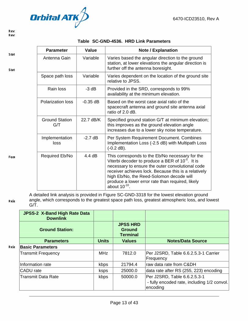
4.4.5 HRD Link Budget Analysis The link budget calculation provides an estimate of the margin necessary to provide a specific level of operation. A bit error rate (BER) of 1 error in 10^8 bits transmitted is desired. The analysis uses conservative and worst case parameter estimates to bound the estimate. Table SC-GND-4536 provides some of the key parameters in the link calculation and a description of the parameter.
Table SC-GND-4536. HRD Link Parameters
Parameter Value Note / Explanation Elevation Angle 5 The lowest elevation angle, which results in the
greatest path loss and atmospheric attenuation.
Transmit Power 10 Watts The EOL specified value of the transmitter.
Passive loss 0.5 dB The maximum loss estimate between either transmitter and its respective antenna.
6470-ICD23510, Rev A
Page 13 of 43
Table SC-GND-4536. HRD Link Parameters
Parameter Value Note / Explanation Antenna Gain Variable Varies based the angular direction to the ground
station, at lower elevations the angular direction is further off the antenna boresight.
Space path loss Variable Varies dependent on the location of the ground site relative to JPSS.
Rain loss -3 dB Provided in the SRD, corresponds to 99% availability at the minimum elevation.
Polarization loss -0.35 dB Based on the worst case axial ratio of the spacecraft antenna and ground site antenna axial ratio of 2.0 dB.
Ground Station G/T
22.7 dB/K Specified ground station G/T at minimum elevation; this improves as the ground elevation angle increases due to a lower sky noise temperature.
Implementation loss
-2.7 dB Per System Requirement Document. Combines Implementation Loss (-2.5 dB) with Multipath Loss (-0.2 dB).
Required Eb/No 4.4 dB This corresponds to the Eb/No necessary for the Viterbi decoder to produce a BER of 10-5. It is necessary to ensure the outer convolutional code receiver achieves lock. Because this is a relatively high Eb/No, the Reed-Solomon decode will produce a lower error rate than required, likely about 10-10.
A detailed link analysis is provided in Figure SC-GND-3318 for the lowest elevation ground angle, which corresponds to the greatest space path loss, greatest atmospheric loss, and lowest G/T.
JPSS-2 X-Band High Rate Data Downlink
Ground Station: JPSS HRD
Ground Terminal
Parameters Units Values Notes/Data Source Basic Parameters Transmit Frequency MHz 7812.0 Per J2SRD, Table 6.6.2.5.3-1 Carrier
Frequency Information rate kbps 21794.4 raw data rate from C&DH CADU rate ksps 25000.0 data rate after RS (255, 223) encoding Transmit Data Rate kbps 50000.0 Per J2SRD, Table 6.6.2.5.3-1
- fully encoded rate, including 1/2 convol. encoding

6470-ICD23510, Rev A
Page 14 of 43
JPSS-2 X-Band High Rate Data Downlink
Ground Station: JPSS HRD
Ground Terminal
Parameters Units Values Notes/Data Source Modulation Symbol Rate ksps 25000.0 OQPSK: 2 bit = 1 symbol Min. Ground Elevation Angle degrees 5 Per J2SRD-1589, min. Ground Elevation
angle Spacecraft Altitude km 824 SC Antenna Max Nadir Angle degrees 61.91 angle off nadir +Z, corresponds to 5 deg.
min. ground El angle Range km 2835.15 Range at 5 degree ground Elevation
Angle
Transmit Parameters Transmitter Power W 10 min. EOL Tx power req. to L3-CE dBm 40.00 Transmitter Network Loss dB -1.2 Calculated from Inputs on Block Diagram Spacecraft Antenna Gain dBi 6.20 Earth Coverage antenna gain at 61.9
deg. EIRP dBm 45.02
Channel Parameters Space Path Loss dB -179.35 Link Availability % 99.0% Excess Path Loss dB -3.00 PER J2 SRD-1502, Includes Scintillation
for 0.99 Availability for JPSS HRD Ground Terminal, assumed value (Hawaii X-Band)
Pointing Loss dB 0.00 Per J2SRD-1585 Included in 22.7 dB/K per table footnote
Polarization Loss dB -0.33 Based on S/C AR of 2.8 dB and GS AR of 2.0 (Estimated, J2SRD-1561), for Beta=90
Receiver Parameters Ground Station Receiver G/T dB/K 22.70 Per J2SRD-1518, (SRD REV D3)
Minimum at 5° Includes pointing loss
Power Summary Received Isotropic Power at Ground Station
dBm -137.66 Received power into an isotropic (0 dB gain) antenna

6470-ICD23510, Rev A
Page 15 of 43
JPSS-2 X-Band High Rate Data Downlink
Ground Station: JPSS HRD
Ground Terminal
Parameters Units Values Notes/Data Source Boltzmann's Constant dBW/K/
Hz -228.60
C/No at Ground Station dB-Hz 83.64
Viterbi Decoder Margin Analysis Code symbol rate into Viterbi Decoder
ksps 50000.00 over-the-air transmit data rate
Bit Rate out of Viterbi Decoder kbps 25000.00 CC encoding removed; equals CADU Rate, which includes Reed-Solomon Coding (255, 223, I = 5)
- RS Symbol Rate dB-Hz 74.0 Received Eb/No dB 9.7 Implementation / Multipath Loss dB -2.70 Per J2SRD-1586 and J2SRD-1587 Calculated Eb/No dB 6.96 Target BER 1.00E-05 After convolutional decoding portion Required Eb/No per SRD 4.4 Per J2SRD-1590 Viterbi Decoder Margin 2.6 Per J2SRD-1589, HRD Margin
requirement > 1.0 dB at 5 deg. El angle
Concatenated Code Margin Analysis
Bit Rate kbps 21,794.371 Information Rate (Concat coding removed)
Info Rate in dB-Hz dB-Hz 73.38 Received Eb/No dB 10.26 Implementation /Multipath Loss dB -2.70 Per J2SRD-1586 and J2SRD-1587
(Added 0.2 dB Multipath Loss to Impl. Loss)
Calculated Eb/No dB 7.56 Target BER 1.00E-08 after all decoding (CC + RS) Required Eb/No dB 2.70 Theoretical Eb/No = 2.7 dB for RS + CC
with Interleave Concatenated BER margin dB 4.9
Figure SC-GND-3318. HRD Detailed Link Calculation

6470-ICD23510, Rev A
Page 16 of 43
5 COMMUNICATIONS INTERFACE REQUIREMENTS
5.1 JPSS Polar Ground Station Requirements
5.1.1 SvalSat For S-band, this receive station's worst case G/T is 19.4 dB/K (SG-22).
5.1.2 McMurdo This section is not applicable to the Satellite HRD to DBS RF ICD.
5.1.3 FCDAS This section is not applicable to the Satellite HRD to DBS RF ICD.
5.1.4 TrollSat This section is not applicable to the Satellite HRD to DBS RF ICD.
5.1.5 White Sands Complex (WSC) This section is not applicable to the Satellite HRD to DBS RF ICD.
5.1.6 Direct Broadcast Ground Station This receive station's worst case G/T is 22.7 dB/K.
5.2 Ground Test Interface Requirements
5.2.1 RF Compatibility Testing The spacecraft will be manufactured and tested in Gilbert, Arizona. The spacecraft interfaces with JPSS ground system and NASA Space Network. During spacecraft Integration and Testing there are several tests between the spacecraft and external interfaces. This section is intended to define the interface between the spacecraft and the JPSS NSOF/JPSS Ground System.
The data transferred between the JPSS NSOF/JPSS Ground System and the Spacecraft GSE consists of commands for uplink, and S-band telemetry and Ka-band Stored Mission Data (SMD) for downlink. X-band (HRD) is not transferred across this interface.
The Orbital I&T encryptor can be switched in/out as needed depending upon test configuration requirements. During normal I&T commanding (when encrypted commanding is enabled), the Orbital encryptor is in the command path. When commanding from the JPSS NSOF/JPSS Ground System, the Orbital encryptor can be switched out. This will allow JPSS NSOF/JPSS Ground System encrypted commands to be sent to the spacecraft using the JPSS NSOF/JPSS Ground System encryptor in place of the Orbital I&T encryptor.
The Government is responsible for RF compatibility testing.
The Spacecraft will support RF characterization of the X-band link concurrently with the RF compatibility testing. X-band characterization will be conducted by GSFC.
5.2.2 JPSS Compatibility Test (JCT) Rack This section is not applicable to the Satellite HRD to DBS RF ICD.
6470-ICD23510, Rev A
Page 17 of 43
5.2.3 External Network Interface (JPSS WAN to JCT Rack) [SC-GND-3561] The government shall provide any external interfaces necessary to enable
communications between the JPSS NSOF/JPSS Ground System GSE and external networks (i.e. the non-Orbital side of the interface). This includes routers, switches, firewalls, backbone data circuits, etc.
5.3 RF Spectral Requirements [SC-GND-2128] The Spacecraft shall comply with National Telecommunications and
Information Administration (NTIA) Spectrum Standards.
[SC-GND-2130] The Spacecraft shall comply with National Telecommunications and Information Administration (NTIA) and International Telecommunications Union (ITU) and Space Frequency Coordination Group (SFCG).
[SC-GND-3217] The Spacecraft shall be compliant with ITU Radiocommunications Sector Radio Regulations, RR Article 21.16, Table 21-4
6 COMMANDS This section is not applicable to the Satellite HRD to Direct Broadcast Stations (DBS) RF ICD.
7 TELEMETRY AND MISSION DATA
7.1 Downlink/Return Link Data Common to Multiple Links
7.1.1 General The Spacecraft will use CCSDS Recommendations for Advanced Orbiting Systems - Space Data Link Protocol 732.0-B-3 for all telemetry and science data streams.
The spacecraft operator will limit transmissions to periods when they are in contact with a receiving earth station or data relay satellite.
The spacecraft operator will be prepared to temporarily switch off emissions from the SC as per SFCG procedures for Inter-Agency Frequency Coordination (RES A12-1).
7.1.2 Space Packets
7.1.2.1 Space Packet Overview The Spacecraft will use CCSDS Recommendations for Space Packet Protocol 133.0-B-1 for all command and telemetry packets.
The bulk of the information about Randomization, Coding and Frame Synchronization falls under the link-specific sections (in appropriate ICDs, Section 7.2 for S-Band, Section 7.3 for Ka-Band, and Section 7.4 for Ka-Band).
[SC-GND-1121] A Space Packet shall encompass the major fields, positioned contiguously, in the following sequence:
a. Packet Primary Header (6 octets)
b. Packet Data Field (up to 65527 octets)
The Spacecraft generates non-segmented packets. Instruments may generate either non-segmented packets or segmented packets. The structural components of non-segmented packets are shown in Figure SC-GND-1124.

6470-ICD23510, Rev A
Page 18 of 43
PacketPrimaryHeader
Packet Secondary HeaderPacket User Data Field
Space Packet
6 Bytes 8 Bytes Up to 65519 Bytes
Packet Data Field
Time Code
Figure SC-GND-1124. Space Packet Structural Components: Non-Segmented Packets
For segmented packets, the structural components of the first segment of the space packet are shown in Figure SC-GND-8008. The presence of a secondary header in a given packet type will provided in the JPSS 6470-ML31100 C&T Handbook [CDRL OPS-2].
PacketPrimaryHeader
Packet Secondary HeaderPacket User Data Field
Space Packet
6 Bytes 8 Bytes 65517 Bytes
Packet Data Field
Time CodePCS Type# of Packet
Segments minus 1
1 Byte
Spare
1 Byte
Figure SC-GND-8008. Space Packet Structural Components: First Segment of Segmented Packets
For segmented packets, the structural components of the middle and last segments of the space packet are shown in Figure SC-GND-3916.
PacketPrimaryHeader Packet User Data Field
Space Packet
6 Bytes Up to 65527 Bytes
Packet Data Field
Figure SC-GND-3916. Space Packet Structural Components:
Middle and Last Segments of Segmented Packets

6470-ICD23510, Rev A
Page 19 of 43
7.1.2.2 Packet Primary Header
7.1.2.2.1 General [SC-GND-1127] The Packet Primary Header shall consist of four fields, positioned
contiguously, in the following sequence: a. Packet Version Number (3 bits) b. Packet Identification Field (13 bits) c. Packet Sequence Control Field (16 bits) d. Packet Data Length (16 bits).
The format of the Packet Primary Header is shown in Figure SC-GND-1129.
PacketVersion Number
Packet Sequence Control
Packet Sequence Count or Packet Name
Packet Primary Header
2 Bytes 2 Bytes 2 Bytes
Packet Identification
3 bits
PacketData
Length
16 bits
PacketType
1 bit
Sec. Hdr. Flag1 bit
Application Process Identifier11 bits
Sequence Flags
2 bits 14 bits
Figure SC-GND-1129. Packet Primary Header
7.1.2.2.2 Packet Version Number [SC-GND-1131] Bits 0-2 of the Packet Primary Header shall contain the (binary encoded)
Packet Version Number.
[SC-GND-1132] For S-band telemetry, the Packet Version Number shall be set to '000'. This identifies the data unit as a Space Packet.
7.1.2.2.3 Packet Identification
7.1.2.2.3.1 General [SC-GND-1135] Bits 3-15 of the Packet Primary Header shall contain the Packet Identification
Field.
[SC-GND-1136] The Packet Identification field shall be sub-divided into three sub-fields as follows: a. Packet Type (1 bit) b. Secondary Header Flag (1 bit) c. Application Process Identifier (11 bits)
7.1.2.2.3.2 Packet Type [SC-GND-1138] Bit 3 of the Packet Primary Header shall contain the Packet Type.
The Packet Type is used to distinguish Packets used for telemetry (or reporting) from Packets used for telecommand (or requesting).

6470-ICD23510, Rev A
Page 20 of 43
[SC-GND-1140] For telemetry, the Packet Type bit shall be set to '0'.
7.1.2.2.3.3 Secondary Header Flag [SC-GND-1142] Bit 4 of the Packet Primary Header shall contain the Secondary Header Flag.
[SC-GND-1143] The Secondary Header Flag shall indicate the presence or absence of the Packet Secondary Header within this Space Packet.
[SC-GND-2743] The Secondary Header Flag shall be set to '1' if a Packet Secondary Header is present, and '0' if a Packet Secondary Header is not present.
7.1.2.2.3.4 Application Process Identifier [SC-GND-1147] Bits 5-15 of the Packet Primary Header shall contain the APID.
[SC-GND-4414] The instruments and spacecraft shall assign application process identifiers (APIDs) within the range specified in SC-GND-4415 APID Range Assignments.
Table SC-GND-4415. APID Range Assignments
Packet Source APID Range (Decimal)
JPSS 2/3/4 Spacecraft 0 – 399, 1500 – 1549, 1800 – 1999
ATMS 450 - 543 OMPS 544 - 649 VIIRS 650 - 899 RBI 1000 - 1100 CrIS 1200 - 1449
7.1.2.2.4 Packet Sequence Control
7.1.2.2.4.1 General [SC-GND-1152] Bits 16-31 of the Packet Primary Header shall contain the Packet Sequence
Control Field.
[SC-GND-1153] The Packet Sequence Control field shall be sub-divided into two sub-fields as follows:
a. Sequence Flags (2 bits)
b. Packet Sequence Count (14 bits)
7.1.2.2.4.2 Sequence Flags [SC-GND-1155] Bits 16-17 of the Packet Primary Header shall contain the Sequence Flags.
[SC-GND-1156] The Sequence Flags shall be set as follows:
a. '00' if the Space Packet contains a continuation segment of User Data
b. '01' if the Space Packet contains the first segment of User Data
c. '10' if the Space Packet contains the last segment of User Data
d. '11' if the Space Packet contains unsegmented User Data.

6470-ICD23510, Rev A
Page 21 of 43
7.1.2.2.4.3 Packet Sequence Count [SC-GND-1159] Bits 18-31 of the Packet Primary Header shall contain the Packet Sequence
Count.
[SC-GND-1161] The Packet Sequence Count shall provide the sequential binary count of each Space Packet generated by the user application identified by the APID.
[SC-GND-1162] The Packet Sequence Count shall be continuous (modulo-16384).
[SC-GND-4416] The packet sequence count in the primary header in a CCSDS packet shall only be 0 by virtue of initialization or a count rollover.
A re-setting of the Packet Sequence Count before reaching 16383 should not take place unless it is unavoidable.
Note: Examples of unavoidable:
a. Performing a reset of the hardware will cause the sequence counters to reset. b. Resetting the sequence counters at the beginning of a contact is not the intended use of
the counters and is considered avoidable.
7.1.2.2.5 Packet Data Length [SC-GND-1165] Bits 32-47 of the Packet Primary Header shall contain the Packet Data
Length.
[SC-GND-1166] The Packet Data Length field shall contain a length count (C) that equals one fewer than the length (in octets) of the Packet Data Field.
7.1.2.3 Packet Data Field
7.1.2.3.1 General [SC-GND-1170] For non-segmented packets, the Packet Data Field shall consist of the
following two fields, positioned contiguously, in the following sequence:
a. Packet Secondary Header
b. User Data Field (varies)
[SC-GND-8112] For the first segment of segmented packets, the Packet Data Field shall consist of the following two fields, positioned contiguously, in the following sequence:
a. Packet Secondary Header (10 octets)
b. User Data Field (varies)
[SC-GND-3958] For the middle and last segments of segmented packets, the Packet Data Field shall consist of a variable-length User Data Field.
7.1.2.3.2 Packet Secondary Header
7.1.2.3.2.1 General [SC-GND-1174] For packets that contain a Packet Secondary Header (i.e., the first segment
of segmented packets, and non-segmented packets), the Packet Secondary Header shall immediately follow the Packet Primary Header.

6470-ICD23510, Rev A
Page 22 of 43
[SC-GND-2745] The presence or absence of a Packet Secondary Header shall be signaled by the Secondary Header Flag within the Packet Identification Field.
For non-segmented packets, the Packet Secondary Header will be as shown in Figure SC-GND-1180.
Time Code Field Ancillary Data Field
Packet Secondary Header
8 Bytes 0 Bytes (not used)
Figure SC-GND-1180. Packet Secondary Header: Non-Segmented Packets For the first segment of segmented packets, the Packet Secondary Header will be as shown in Figure SC-GND-4081. The middle and last segments of segmented packets do not contain a Packet Secondary Header.
Time Code Field
PCS Type# of Packet Segments minus 1
Packet Secondary Header
8 Bytes 1 Byte
Spare
1 Byte
Figure SC-GND-4081. Packet Secondary Header: First Segment of Segmented Packets
7.1.2.3.2.2 Time Code Field [SC-GND-3904] The spacecraft reference epoch shall be the NASA Epoch of Jan 1, 1958,
00:00:00 UTC (TAI).
The packet Secondary Header Time Code Field describes when the packet was assembled.
Spacecraft time is defined by a Seconds field and a Subseconds field internally. The Seconds and Subseconds fields are essentially counters that contain the elapsed time since a given epoch (specific moment in time). The Seconds field is set by the ground. The Subseconds field is controlled by software to be synchronized to the SC GPS output.
Flight software does the format conversion and puts the time tags on packets. When FSW is not running, the spacecraft provides hardware telemetry generated by the UDL. Hardware telemetry has the seconds-since-epoch and subseconds time format in telemetry packet secondary headers. The only time the ground system will receive hardware telemetry packets is during launch before spacecraft power-up of the CPU, and if the spacecraft were to reboot in orbit during a ground contact.

6470-ICD23510, Rev A
Page 23 of 43
[SC-GND-4403] The CCSDS Time Code field in the packet Secondary Header shall be spacecraft time presented in CCSDS Day Segmented Time Code (CDS) format per CCSDS Recommendations for Space Data System Standards – Time Code Formats, CCSDS 301.0-B-2 for all software packets generated by the instruments or spacecraft processor.
The Spacecraft does not transmit the preamble as defined in CCSDS 301.0-B-2.
[SC-GND-4584] For software telemetry packets, the Packet Secondary Header Time Code Field shall be subdivided as follows and as shown in Figure SC-GND-3970:
a. Day (16 bits)
b. Milliseconds of day (32 bits)
c. Microseconds of millisecond (16 bits)
DAY ms of day µs of day
Segment Width
16 bits 32 bits 16 bits
Figure SC-GND-3970. CCSDS Day Segmented Time Format Each segment above is a right-adjusted binary counter. The CCSDS recommended day segment is a continuous counter of days from 1958 January 1 starting with 0.
[SC-GND-3971] Days shall be an unsigned 16-bit integer of the number of days since the spacecraft epoch.
[SC-GND-4089] Milliseconds of day shall be an unsigned 32-bit integer of the number of milliseconds since midnight UTC of the current day.
[SC-GND-3341] Microseconds of millisecond shall be an unsigned 16-bit integer of the number of microseconds since the beginning of the current millisecond.
[SC-GND-3972] The range for milliseconds of day shall be 0 to 86,399,999 for days without leap-seconds, and 0 to either 86,400,999 or 86,398,999 for days when leap-second adjustments are introduced.
[SC-GND-4090] The range for microseconds of millisecond shall be 0 to 999.
[SC-GND-4430] The CCSDS Time Code field in the packet Secondary Header of hardware-generated packets shall be spacecraft time presented in CCSDS Unsegmented Time Code (CUC) format.
[SC-GND-1183] For hardware telemetry packets, the Packet Secondary Header Time Code Field shall be sub-divided as follows:
a. Seconds Field (32 bits)
b. Reserved Spare (8 bits)
c. Subseconds Field (24 bits)
6470-ICD23510, Rev A
Page 24 of 43
[SC-GND-2873] For hardware telemetry packets, the Seconds field shall have a length of 32 bits.
The hardware time is an unsigned integer of the monotonically incremented number of seconds since the spacecraft epoch.
[SC-GND-3343] For hardware telemetry packets, the Reserved Spare field shall be set to '0x00'.
[SC-GND-2874] For hardware telemetry packets, the Subseconds field shall have a length of 24 bits. The spacecraft uses a 10 MHz oscillator to drive this timer. One bit value is the time required for one cycle of the 10 MHz oscillator (1 bit = 0.0000001 seconds).
7.1.2.3.2.3 Number of Packet Segments [SC-GND-4418] For the first segment of segmented packets, the ninth octet of data in the
secondary header shall be the number of packet segments field containing the total number of packets expected for this CCSDS packet set minus one.
[SC-GND-4419] For the first segment of segmented packets, the tenth octet of data in the secondary header shall be spare bits.
7.1.2.3.2.4 Ancillary Data Field The Ancillary Data Field is 0 bytes and is not used by the spacecraft.
7.1.2.4 User Data Field [SC-GND-1190] The User Data Field shall immediately follow the Packet Secondary Header if
present. The User Data Field shall immediately follow the Packet Primary Header if Secondary Header is not present.
[SC-GND-1192] The User Data Field shall consist of an integral number of octets.
[SC-GND-8113] For packets that contain a Packet Secondary Header of length 8 bytes (non-segmented packets), the User Data Field shall have a maximum length of 65519 bytes.
[SC-GND-8115] For packets that contain a Packet Secondary Header of length 10 bytes (first segment of segmented packets), the User Data Field shall have a maximum length of 65517 bytes.
[SC-GND-2897] For packets that do not contain a Packet Secondary Header (middle and last segments of segmented packets), the User Data Field shall have a maximum length of 65527 bytes.
7.1.3 Transfer Frame Spacecraft telemetry will be in accordance with the CCSDS Recommendations for Advanced Orbiting Systems - Space Data Link Protocol 732.0-B-3 for all telemetry and science data streams. The telemetry format from the Spacecraft will be in the form of a CCSDS Advanced Orbiting Systems (AOS) Transfer Frame. The AOS Transfer Frame is the data structure that provides fixed-length, byte-aligned data blocks used for transmitting data from the Spacecraft to the ground.
6470-ICD23510, Rev A
Page 25 of 43
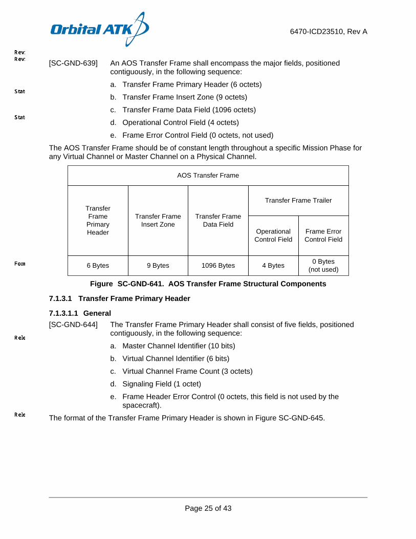
[SC-GND-639] An AOS Transfer Frame shall encompass the major fields, positioned contiguously, in the following sequence:
a. Transfer Frame Primary Header (6 octets)
b. Transfer Frame Insert Zone (9 octets)
c. Transfer Frame Data Field (1096 octets)
d. Operational Control Field (4 octets)
e. Frame Error Control Field (0 octets, not used)
The AOS Transfer Frame should be of constant length throughout a specific Mission Phase for any Virtual Channel or Master Channel on a Physical Channel.
TransferFrame
PrimaryHeader
Transfer Frame Insert Zone
Transfer Frame Data Field
AOS Transfer Frame
6 Bytes 9 Bytes 1096 Bytes
Transfer Frame Trailer
Operational Control Field
Frame Error Control Field
4 Bytes 0 Bytes(not used)
Figure SC-GND-641. AOS Transfer Frame Structural Components
7.1.3.1 Transfer Frame Primary Header
7.1.3.1.1 General [SC-GND-644] The Transfer Frame Primary Header shall consist of five fields, positioned
contiguously, in the following sequence:
a. Master Channel Identifier (10 bits)
b. Virtual Channel Identifier (6 bits)
c. Virtual Channel Frame Count (3 octets)
d. Signaling Field (1 octet)
e. Frame Header Error Control (0 octets, this field is not used by the spacecraft).
The format of the Transfer Frame Primary Header is shown in Figure SC-GND-645.

6470-ICD23510, Rev A
Page 26 of 43
Master Channel ID
Transfer Frame Primary Header
2 Bytes
Transfer Frame Version Number
2 bits
Spacecraft ID
8 bits
Virtual Channel
ID
Virtual Channel Frame Count
3 Bytes
Signaling Field
Replay Flag
VC Frame Count Usage Flag
RSVD Spare
VC Frame Count Cycle
Frame Header Error
Control
1 Byte 0 Bytes (not used)
6 bits 1 bit 1 bit 2 bits 4 bits
Figure SC-GND-645. Transfer Frame Primary Header
7.1.3.1.2 Master Channel Identifier
7.1.3.1.2.1 General [SC-GND-664] Bits 0-9 of the Transfer Frame Primary Header shall contain the Master
Channel Identifier (MCID).
[SC-GND-665] The Master Channel Identifier shall consist of:
a. Transfer Frame Version Number (2 bits)
b. Spacecraft Identifier (8 bits).
7.1.3.1.2.2 Transfer Frame Version Number [SC-GND-666] Bits 0-1 of the Transfer Frame Primary Header shall contain the Transfer
Frame Version Number.
[SC-GND-667] The Transfer Frame Version Number field shall be set to '01'. This identifies the data unit as a Transfer Frame.
7.1.3.1.2.3 Spacecraft ID [SC-GND-668] Bits 2-9 of the Transfer Frame Primary Header shall contain the Spacecraft
ID (SCID).
The Spacecraft ID provides the identification of the spacecraft which is associated with the data contained in the Transfer Frame.
[SC-GND-671] The Spacecraft ID shall be set to '0xB1' ('10110001') JPSS 2, '0xB2' ('10110010') for JPSS 3, and '0xB3' ('10110011') for JPSS 4.
7.1.3.1.3 Virtual Channel ID [SC-GND-672] Bits 10-15 of the Transfer Frame Primary Header shall contain the Virtual
Channel Identifier (VCID).
Additional details regarding VCIDs are specific to each link and are therefore addressed in the link-specific sections (in appropriate ICDs, Section 7.2.3.1.3 for S-Band, Section 7.3.3.1.3 for Ka-Band, and Section 7.4.3.1.3 for X-Band).

6470-ICD23510, Rev A
Page 27 of 43
7.1.3.1.4 Virtual Channel Frame Count [SC-GND-675] Bits 16-39 of the Transfer Frame Primary Header shall contain the Virtual
Channel Frame Count.
[SC-GND-676] The Virtual Channel Frame Count field shall contain a sequential binary count (modulo-16,777,216) of each Transfer Frame transmitted within a specific Virtual Channel.
A resetting of the Virtual Channel Frame Count before reaching 16,777,215 should not take place unless it is unavoidable.
Note: Examples of unavoidable:
a. Performing a reset of the DFB will cause the sequence counters to reset. b. Resetting the sequence counters at the beginning of a contact is not the intended use of
the counters and is considered avoidable.
7.1.3.1.5 Signaling Field
7.1.3.1.5.1 General [SC-GND-678] Bits 40-47 of the Transfer Frame Primary Header shall contain the Signaling
Field.
The Signaling Field should be used to alert the receiver of the Transfer Frames with respect to functions that: (a) may change more rapidly than can be handled by management, or; (b) provide a significant cross-check against manual or automated setups for fault detection and isolation purposes.
[SC-GND-680] The Signaling Field shall be subdivided into four sub-fields as follows:
a. Replay Flag (1 bit)
b. Virtual Channel (VC) Frame Count Cycle Use Flag (1 bit)
c. Reserved Spares (2 bits)
d. Virtual Channel Frame Count Cycle (4 bits).
7.1.3.1.5.2 Replay Flag [SC-GND-681] Bit 40 of the Transfer Frame Primary Header shall contain the Replay Flag.
Recognizing the need to store Transfer Frames during periods when the space link is unavailable, and to retrieve them for subsequent replay when the link is restored, this flag alerts the receiver of the Transfer Frames with respect to its ‘realtime’ or ‘replay’ status. Its main purpose is to discriminate between realtime and replay Transfer Frames when they both may use the same Virtual Channel.
[SC-GND-683] The Replay Flag shall be used as follows:
a. ‘0’ = Realtime Transfer Frame (Realtime SOH, all frames on HRD and SMD)
b. ‘1’ = Replay Transfer Frame (Stored SOH)

6470-ICD23510, Rev A
Page 28 of 43
7.1.3.1.5.3 VC Frame Count Cycle Usage Flag [SC-GND-684] Bit 41 of the Transfer Frame Primary Header shall contain the VC Frame
Count Cycle Use Flag.
Because VC Frame Count Cycle Usage Flag requirements are not common to all links, they are described under link-specific sections.
7.1.3.1.5.4 Reserved Spare [SC-GND-686] Bits 42-43 of the Transfer Frame Primary Header shall contain the reserved
spare.
[SC-GND-687] The Reserved Spare field shall be set to ‘00’.
7.1.3.1.5.5 VC Frame Count Cycle [SC-GND-2879] Bits 44-47 of the Transfer Frame Primary Header shall contain the Virtual
Channel Frame Count Cycle Field.
When used, the VC Frame Count Cycle effectively extends the Virtual Channel Frame Count from 24 to 28 bits. Each time the Virtual Channel Frame Count returns to zero, the VC Frame Count Cycle should be incremented.
The VC Frame Count Cycle field is not common across all links, and is therefore addressed in link-specific sections.
7.1.3.1.6 Frame Header Error Control The spacecraft does not utilize the Frame Header Error Control field of the Transfer Frame Primary Header.
7.1.3.2 Transfer Frame Insert Zone The Transfer Frame Insert Zone immediately follows the Transfer Frame Primary Header and is described in each link-specific section.
7.1.3.3 Transfer Frame Data Field
7.1.3.3.1 Overview [SC-GND-708] The Transfer Frame Data Field shall immediately follow the Transfer Frame
Insert Zone.
[SC-GND-709] The Transfer Frame Data Field shall have a length of 1096 Bytes.
[SC-GND-710] The Transfer Frame Data Field shall contain one Multiplexing Protocol Data Unit (M_PDU) or Idle Data.
[SC-GND-711] Idle data shall only appear in Idle Transfer Frames (i.e., if a Virtual Channel transfers M_PDUs, every Transfer Frame of that Virtual Channel should contain an M_PDU).
[SC-GND-712] An Idle Transfer Frame with a Data Field containing only Idle Data shall be transmitted when no valid transfer frame is available.
[SC-GND-2886] The Virtual Channel ID of an Idle Transfer Frame shall be set to the value of ‘all ones’
[SC-GND-2887] The ‘idle’ pattern shall be selectable. The spacecraft has a 16 bit selectable pattern with a default idle pattern of '0xD67A'.

6470-ICD23510, Rev A
Page 29 of 43
7.1.3.3.2 Multiplexing Protocol Data Unit
7.1.3.3.2.1 Overview [SC-GND-715] The Multiplexing Protocol Data Unit (M_PDU) shall immediately follow the
Transfer Frame Insert Zone.
[SC-GND-716] The length of the M_PDU shall be 1096 Bytes.
[SC-GND-714] The M_PDU shall be divided as follows:
a. M_PDU Header (2 octets)
b. M_PDU Packet Zone (1094 octets).
[SC-GND-717] The M_PDU Header shall be sub-divided as follows:
a. Reserved Spare (5 bits)
b. First Header Pointer (11 bits).
The format of the M_PDU is shown in Figure SC-GND-719.
M_PDU HEADER
END OF PREVIOUS
CCSDS PACKET #k
FIRST HEADER POINTER
11 bits
RSVD SPARE
5 bits
CCSDS PACKET
#k+1
CCSDS PACKET
#m
START OF CCSDS PACKET
#m+1
M_PDU PACKET ZONE
Figure SC-GND-719. Multiplexing Protocol Data Unit (M_PDU)
7.1.3.3.2.2 M_PDU Header [SC-GND-723] Bits 0-4 of the M_PDU Header shall contain the Reserved Spare.
[SC-GND-724] The Reserved Spare field shall be set to ‘00000’.
[SC-GND-725] Bits 5-15 of the M_PDU Header shall contain the First Header Pointer.
[SC-GND-726] The First Header Pointer shall contain the position of the first octet of the first new Packet that starts in the M_PDU Packet Zone. The first octet in this zone is assigned the number 0.
[SC-GND-728] If no Packet starts in the M_PDU Packet Zone, the First Header Pointer shall be set to ‘all ones’.
7.1.3.3.2.3 M_PDU Packet Zone [SC-GND-730] The M_PDU Packet Zone shall immediately follow the M_PDU Header.
[SC-GND-732] Packets shall be inserted contiguously and in forward order into the M_PDU Packet Zone.

6470-ICD23510, Rev A
Page 30 of 43
7.1.3.4 Operational Control Field The Operational Control Field is present on all links. On S-band, the OCF is synonymous with the Command Link Control Word (Sections 7.2.3.4 and 7.2.3.5). For Ka and X-band downlinks, the OCF consists of a static value (Sections 7.3.3.4 and 7.4.3.4 respectively).
7.1.3.5 Frame Error Control Field The Frame Error Control Field is not utilized by any downlink.
7.1.4 Randomization, Coding and Frame Synchronization
7.1.4.1 Pseudo-Randomizer In order to ensure proper receiver operation, the data stream must be sufficiently random. The Pseudo-Randomizer defined in this section is the required method to ensure sufficient randomness.
The randomizer reduces the probability of false carrier lock, ensures proper bit/symbol synchronization, and avoids false decoder lock.
For further information regarding the pseudo-Randomizer on the X-Band HRD link, refer to Section 7.4.4.2, Pseudo-Randomizer.
7.1.5 Modulation For modulation information, refer to each individual downlink section.
7.1.6 Radio Frequency Characteristics
7.1.6.1 Space-to-Ground (Return) Links [SC-GND-4597] All downlink/return link interfaces shall have a polarization of RHCP.
7.2 S-band Telemetry (TT&C) This section is not applicable to the Satellite HRD to DBS RF ICD.
7.3 Ka-Band Downlink (SMD) This section is not applicable to the Satellite HRD to DBS RF ICD.
7.4 X-Band Telemetry (HRD)
7.4.1 General The Spacecraft will return the following types of data on X-Band:
a. Realtime mission data b. Spacecraft telemetry including attitude and ephemeris data c. Instrument housekeeping data
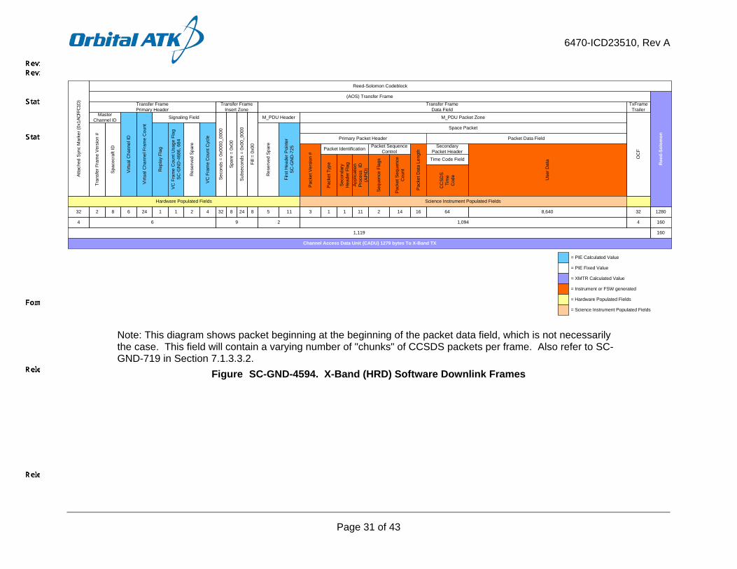
[SC-GND-4361] The Spacecraft shall maintain a constant HRD broadcast rate by using idle Transfer Frames using format as defined in CCSDS 732.0-B-3.
[SC-GND-595] The Spacecraft shall support selectable randomization of the X-Band (HRD) downlink in accordance with CCSDS 131.0-B-2.
The X-band (HRD) protocol stack is summarized in Figure SC-GND-4594. This section will describe each of the elements contained within this figure.
6470-ICD23510, Rev A
Page 31 of 43
1,119
Hardware Populated FieldsV
C F
ram
e C
ount
Cyc
le
Virtu
al C
hann
el F
ram
e C
ount
Tran
sfer
Fra
me
Vers
ion
#
Spa
cecr
aft I
DSignaling FieldMaster
Channel ID
Transfer FramePrimary Header
Virt
ual C
hann
el ID
Rep
lay
Flag
Atta
ched
Syn
c M
arke
r (0x
1ACF
FC1D
)
Res
erve
d Sp
are
Pac
ket V
ersi
on #
Appl
icat
ion
Proc
ess
ID(A
PID
)
Sec
onda
ry
Hea
der F
lag
Pac
ket T
ype
Pack
et D
ata
Leng
th
CC
SD
STi
me
Cod
e
Pack
et S
eque
nce
Cou
nt
Seq
uenc
e Fl
ags
Res
erve
d Sp
are
Packet Identification Packet Sequence Control
Secondary Packet Header
Primary Packet Header Packet Data Field
Space Packet
M_PDU Header M_PDU Packet Zone
Use
r Dat
aTime Code Field
Science Instrument Populated Fields
645 11 3 1111 16142632 41242 8 21 8,640
Transfer FrameData Field
(AOS) Transfer Frame
4 6 2 1,094
32
Transfer FrameInsert Zone
9Se
cond
s =
0x00
00_0
000
Spar
e =
0x00
Fill
= 0x
00
248
Subs
econ
ds =
0x0
0_00
00
8 32
4
OC
F
Ree
d-So
lom
on
1280
160
Channel Access Data Unit (CADU) 1279 bytes To X-Band TX
Reed-Solomon Codeblock
160
TxFrameTrailer
VC F
ram
e C
ount
Usa
ge F
lag
SC-G
ND
-468
6, 6
84
Firs
t Hea
der P
oint
er
SC-G
ND
-725
= PIE Fixed Value
= PIE Calculated Value
= XMTR Calculated Value
= Instrument or FSW generated
= Hardware Populated Fields
= Science Instrument Populated Fields
Note: This diagram shows packet beginning at the beginning of the packet data field, which is not necessarily the case. This field will contain a varying number of "chunks" of CCSDS packets per frame. Also refer to SC-GND-719 in Section 7.1.3.3.2.
Figure SC-GND-4594. X-Band (HRD) Software Downlink Frames
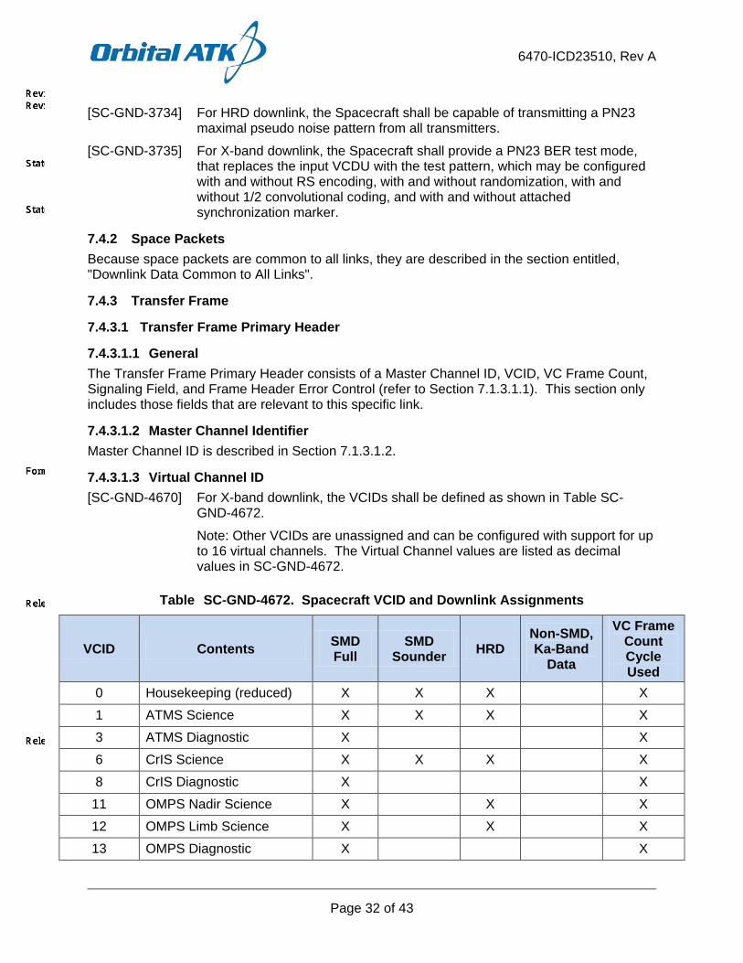
6470-ICD23510, Rev A
Page 32 of 43
[SC-GND-3734] For HRD downlink, the Spacecraft shall be capable of transmitting a PN23 maximal pseudo noise pattern from all transmitters.
[SC-GND-3735] For X-band downlink, the Spacecraft shall provide a PN23 BER test mode, that replaces the input VCDU with the test pattern, which may be configured with and without RS encoding, with and without randomization, with and without 1/2 convolutional coding, and with and without attached synchronization marker.
7.4.2 Space Packets Because space packets are common to all links, they are described in the section entitled, "Downlink Data Common to All Links".
7.4.3 Transfer Frame
7.4.3.1 Transfer Frame Primary Header
7.4.3.1.1 General The Transfer Frame Primary Header consists of a Master Channel ID, VCID, VC Frame Count, Signaling Field, and Frame Header Error Control (refer to Section 7.1.3.1.1). This section only includes those fields that are relevant to this specific link.
7.4.3.1.2 Master Channel Identifier Master Channel ID is described in Section 7.1.3.1.2.
7.4.3.1.3 Virtual Channel ID [SC-GND-4670] For X-band downlink, the VCIDs shall be defined as shown in Table SC-
GND-4672.
Note: Other VCIDs are unassigned and can be configured with support for up to 16 virtual channels. The Virtual Channel values are listed as decimal values in SC-GND-4672.
Table SC-GND-4672. Spacecraft VCID and Downlink Assignments
VCID Contents SMD Full
SMD Sounder HRD
Non-SMD, Ka-Band
Data
VC Frame Count Cycle Used
0 Housekeeping (reduced) X X X X 1 ATMS Science X X X X 3 ATMS Diagnostic X X 6 CrIS Science X X X X 8 CrIS Diagnostic X X
11 OMPS Nadir Science X X X 12 OMPS Limb Science X X X 13 OMPS Diagnostic X X
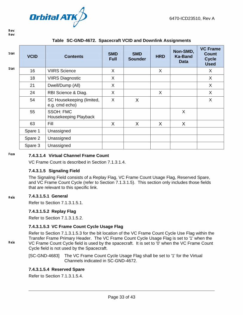
6470-ICD23510, Rev A
Page 33 of 43
Table SC-GND-4672. Spacecraft VCID and Downlink Assignments
VCID Contents SMD Full
SMD Sounder HRD
Non-SMD, Ka-Band
Data
VC Frame Count Cycle Used
16 VIIRS Science X X X 18 VIIRS Diagnostic X X 21 Dwell/Dump (All) X X 24 RBI Science & Diag. X X X 54 SC Housekeeping (limited,
e.g. cmd echo) X X X
55 SSOH: FMC Housekeeping Playback
X
63 Fill X X X X Spare 1 Unassigned Spare 2 Unassigned Spare 3 Unassigned
7.4.3.1.4 Virtual Channel Frame Count VC Frame Count is described in Section 7.1.3.1.4.
7.4.3.1.5 Signaling Field The Signaling Field consists of a Replay Flag, VC Frame Count Usage Flag, Reserved Spare, and VC Frame Count Cycle (refer to Section 7.1.3.1.5). This section only includes those fields that are relevant to this specific link.
7.4.3.1.5.1 General Refer to Section 7.1.3.1.5.1.
7.4.3.1.5.2 Replay Flag Refer to Section 7.1.3.1.5.2.
7.4.3.1.5.3 VC Frame Count Cycle Usage Flag Refer to Section 7.1.3.1.5.3 for the bit location of the VC Frame Count Cycle Use Flag within the Transfer Frame Primary Header. The VC Frame Count Cycle Usage Flag is set to '1' when the VC Frame Count Cycle field is used by the spacecraft. It is set to '0' when the VC Frame Count Cycle field is not used by the Spacecraft.
[SC-GND-4683] The VC Frame Count Cycle Usage Flag shall be set to '1' for the Virtual Channels indicated in SC-GND-4672.
7.4.3.1.5.4 Reserved Spare Refer to Section 7.1.3.1.5.4.

6470-ICD23510, Rev A
Page 34 of 43
7.4.3.1.5.5 VC Frame Count Cycle The VC Frame Count Cycle is used to extend the VCDU counter from 24 to 28 bits.
[SC-GND-8140] The Spacecraft shall generate the 4-bit Virtual Channel Frame Count Cycle field with an initial value of ‘0000’.
[SC-GND-7971] The Spacecraft shall increment the VC Frame Count Cycle each time the VC Frame Count rolls over from all 1' to all 0's.
7.4.3.2 Transfer Frame Insert Zone For the X-band downlink, the JPSS 2/3/4 spacecraft generates a transfer frame insert zone consisting of 9 bytes with a value of 0x00.
7.4.3.3 Transfer Frame Data Field Because Transfer Frame Data Field requirements are common to all links, they are described within Section 7.1.3.3, Transfer Frame Data Field.
7.4.3.4 Operational Control Field [SC-GND-4641] For the X-band downlink, the OCF shall be set to a static value of 0.
7.4.3.5 Frame Error Control Field The Frame Error Control Field is not utilized by the X-band downlink.
7.4.4 Randomization, Coding and Frame Synchronization
7.4.4.1 Reed-Solomon Coding
7.4.4.1.1 Introduction The Reed-Solomon (R-S) code defined in this section is a powerful burst error correcting code. In addition, the code chosen has an extremely low undetected error rate. This means that the decoder can reliably indicate whether or not it can make the proper corrections. To achieve this reliability, proper codeblock synchronization is mandatory.
The Reed-Solomon code may be used alone, and as such it provides an excellent forward error correction capability in a burst-noise channel. The Reed-Solomon code may be concatenated with a convolutional code.
7.4.4.1.2 Specification [SC-GND-4639] The X-band HRD interface shall have a block coding of (255,223) RS, I=5.
[SC-GND-4224] For X-band (HRD) downlink, the Reed-Solomon code shall be applied to the Transfer Frame as shown in Figure SC-GND-4226.
SYNC TRANSFER FRAME(UNCODED)
R-S CHECK SYMBOLS SYNC
ATTACHED SYNC MARKER TRANSMITTED CODEBLOCK
Figure SC-GND-4226. Reed-Solomon Codeblock Partitioning
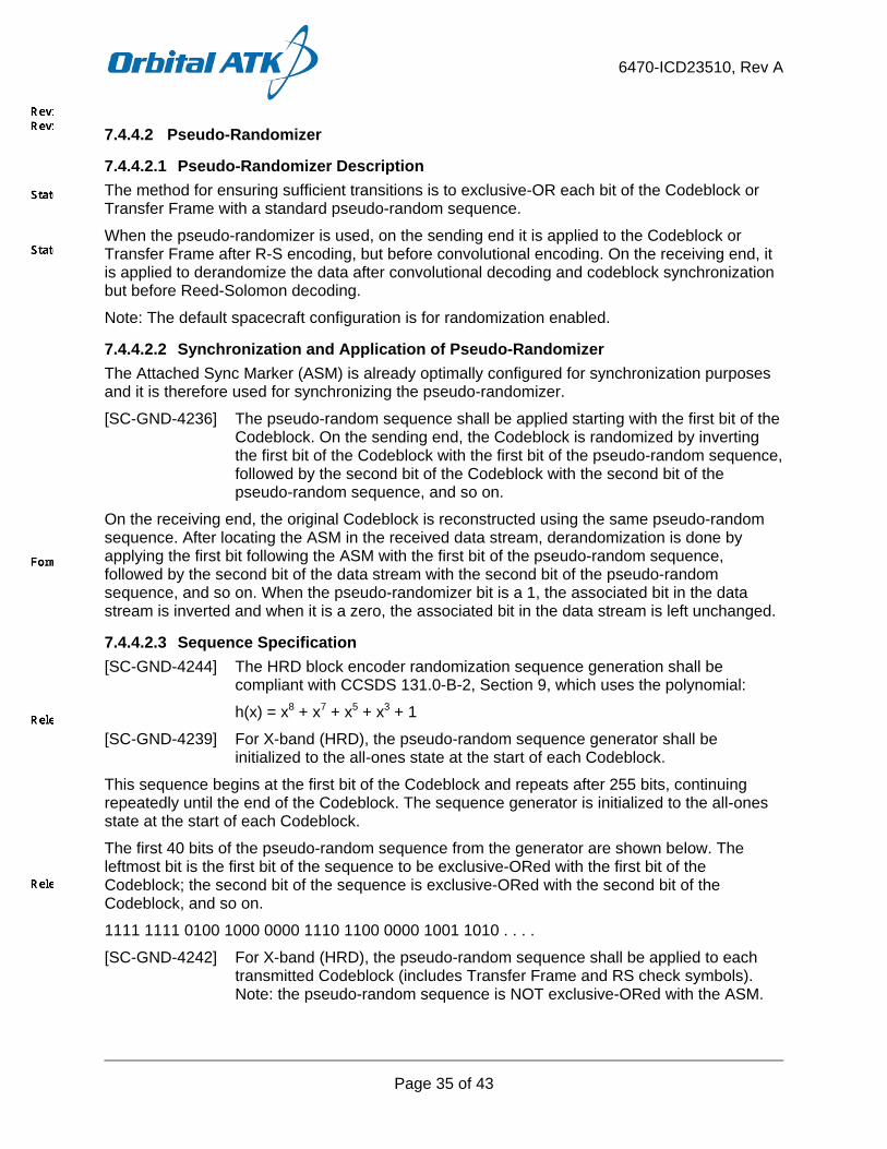
6470-ICD23510, Rev A
Page 35 of 43
7.4.4.2 Pseudo-Randomizer
7.4.4.2.1 Pseudo-Randomizer Description The method for ensuring sufficient transitions is to exclusive-OR each bit of the Codeblock or Transfer Frame with a standard pseudo-random sequence.
When the pseudo-randomizer is used, on the sending end it is applied to the Codeblock or Transfer Frame after R-S encoding, but before convolutional encoding. On the receiving end, it is applied to derandomize the data after convolutional decoding and codeblock synchronization but before Reed-Solomon decoding.
Note: The default spacecraft configuration is for randomization enabled.
7.4.4.2.2 Synchronization and Application of Pseudo-Randomizer The Attached Sync Marker (ASM) is already optimally configured for synchronization purposes and it is therefore used for synchronizing the pseudo-randomizer.
[SC-GND-4236] The pseudo-random sequence shall be applied starting with the first bit of the Codeblock. On the sending end, the Codeblock is randomized by inverting the first bit of the Codeblock with the first bit of the pseudo-random sequence, followed by the second bit of the Codeblock with the second bit of the pseudo-random sequence, and so on.
On the receiving end, the original Codeblock is reconstructed using the same pseudo-random sequence. After locating the ASM in the received data stream, derandomization is done by applying the first bit following the ASM with the first bit of the pseudo-random sequence, followed by the second bit of the data stream with the second bit of the pseudo-random sequence, and so on. When the pseudo-randomizer bit is a 1, the associated bit in the data stream is inverted and when it is a zero, the associated bit in the data stream is left unchanged.
7.4.4.2.3 Sequence Specification [SC-GND-4244] The HRD block encoder randomization sequence generation shall be
compliant with CCSDS 131.0-B-2, Section 9, which uses the polynomial:
h(x) = x8 + x7 + x5 + x3 + 1
[SC-GND-4239] For X-band (HRD), the pseudo-random sequence generator shall be initialized to the all-ones state at the start of each Codeblock.
This sequence begins at the first bit of the Codeblock and repeats after 255 bits, continuing repeatedly until the end of the Codeblock. The sequence generator is initialized to the all-ones state at the start of each Codeblock.
The first 40 bits of the pseudo-random sequence from the generator are shown below. The leftmost bit is the first bit of the sequence to be exclusive-ORed with the first bit of the Codeblock; the second bit of the sequence is exclusive-ORed with the second bit of the Codeblock, and so on.
1111 1111 0100 1000 0000 1110 1100 0000 1001 1010 . . . .
[SC-GND-4242] For X-band (HRD), the pseudo-random sequence shall be applied to each transmitted Codeblock (includes Transfer Frame and RS check symbols). Note: the pseudo-random sequence is NOT exclusive-ORed with the ASM.

6470-ICD23510, Rev A
Page 36 of 43
7.4.4.2.4 Logic Diagram [SC-GND-4248] For X-band (HRD), the result of the pseudo-random sequence shall be
exclusive-ORed each bit in the Codeblock as shown in Figure SC-GND-4249.
Figure SC-GND-4249. Pseudo-Randomizer Logic Diagram
7.4.4.3 Frame Synchronization
7.4.4.3.1 Attached Sync Markers (ASMs)
7.4.4.3.1.1 General Synchronization of the Reed-Solomon encoded Transfer Frame is achieved by using a stream of fixed-length Codeblocks (or encoded Transfer Frames) with an Attached Sync Marker (ASM) between them. Synchronization is acquired on the receiving end by recognizing the specific bit pattern of the ASM in the Physical Channel data stream; synchronization is then customarily confirmed by making further checks.
[SC-GND-4270] For X-band (HRD) downlink, the ASM shall be inserted into the X-band bit stream preceding the randomized RS Encoded Transfer Frame.
The data unit that consists of the ASM and Reed-Solomon Codeblock is called the Channel Access Data Unit (CADU).
[SC-GND-4259] For X-band (HRD) downlink, the ASM shall be acquired for the synchronization of Reed-Solomon decoding.
7.4.4.3.2 RS Encoded Transfer Frame ASM Bit Patterns [SC-GND-4256] For X-band (HRD) downlink, the RS Encoded Transfer Frame ASM shall
have a length of 32-bits (4-octets).
[SC-GND-4257] For X-band (HRD) downlink, the RS Encoded Transfer Frame ASM shall have a hexadecimal pattern of 0x1ACFFC1D. The binary representation of the RS Encoded Transfer Frame ASM is shown in Figure SC-GND-4263.

6470-ICD23510, Rev A
Page 37 of 43
0001 1010 1100 1111 1111 1100 0001 1101
FIRST TRANSMITTED BIT(BIT 0)
LAST TRANSMITTED BIT(BIT 31)
Figure SC-GND-4263. RS Encoded Transfer Frame ASM Bit Pattern
7.4.4.4 Convolutional Coding
7.4.4.4.1 Basic Convolutional Code
7.4.4.4.1.1 Basic Convolutional Code Description The basic convolutional code is a rate (r) 1/2, constraint-length (k) 7 transparent code which is well suited for channels with predominantly Gaussian noise.
The convolutional decoder is a maximum-likelihood (Viterbi) decoder.
It is recommended that soft bit decisions with at least 3-bit quantization be used whenever constraints (such as location of decoder) permit.
7.4.4.4.1.2 Basic Convolutional Code Specification [SC-GND-4267] For X-band (HRD) downlink, the convolutional code shall be a non-systematic
code with the following characteristics:
a. Nomenclature: Convolutional code with maximum-likelihood (Viterbi) decoding.
b. Code rate (r): 1/2 bit per symbol.
c. Constraint length (K): 7 bits.
d. Connection vectors: G1 = '1111001' (171 octal); G2= '1011011' (133 octal).
e. Symbol inversion: On output path of G2.
When a fixed pattern (the fixed part of the convolutionally encoded Attached Sync Marker) in the symbol stream is used to provide node synchronization for the Viterbi decoder, care must be taken to account for any modification of the pattern resulting from the modulating waveform conversion.
A basic convolutional encoder is shown in Figure SC-GND-3535.
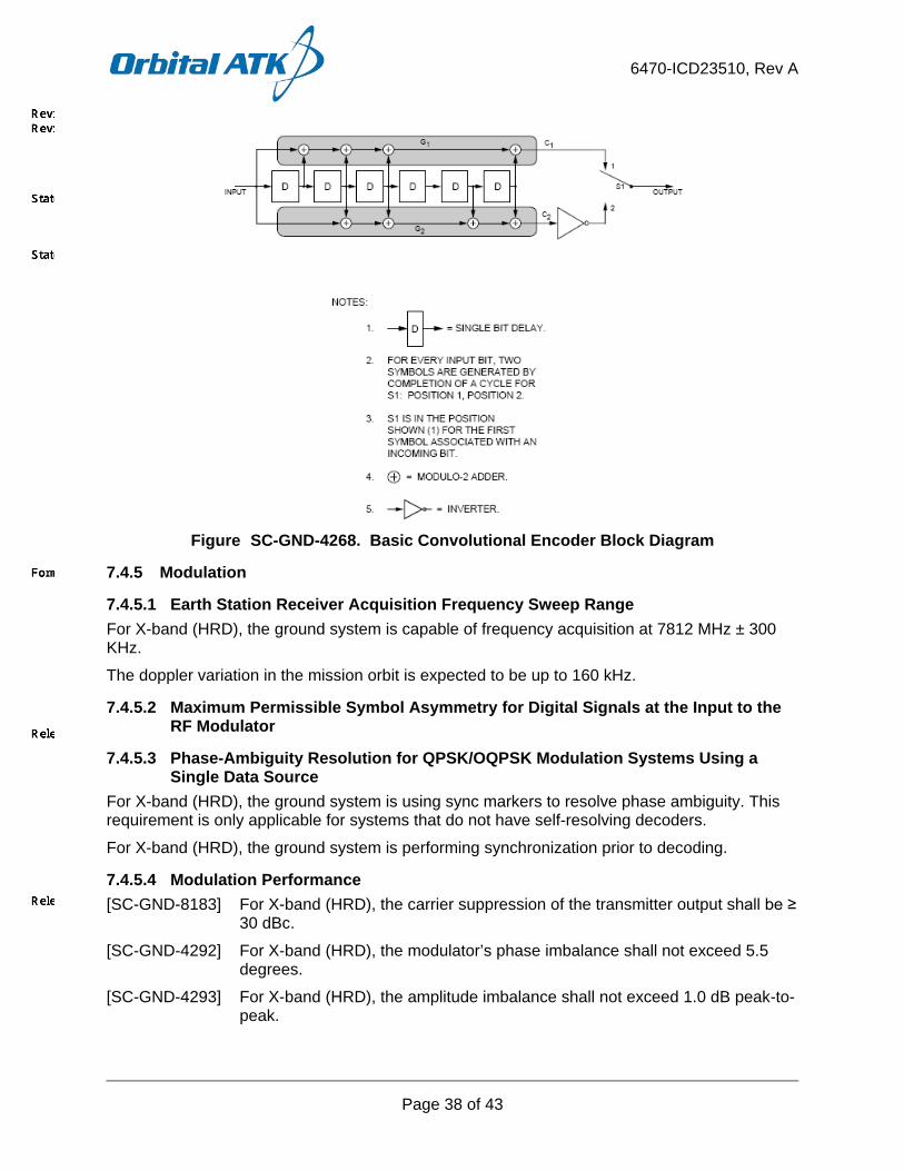
6470-ICD23510, Rev A
Page 38 of 43
Figure SC-GND-4268. Basic Convolutional Encoder Block Diagram
7.4.5 Modulation
7.4.5.1 Earth Station Receiver Acquisition Frequency Sweep Range For X-band (HRD), the ground system is capable of frequency acquisition at 7812 MHz ± 300 KHz.
The doppler variation in the mission orbit is expected to be up to 160 kHz.
7.4.5.2 Maximum Permissible Symbol Asymmetry for Digital Signals at the Input to the RF Modulator
7.4.5.3 Phase-Ambiguity Resolution for QPSK/OQPSK Modulation Systems Using a Single Data Source
For X-band (HRD), the ground system is using sync markers to resolve phase ambiguity. This requirement is only applicable for systems that do not have self-resolving decoders.
For X-band (HRD), the ground system is performing synchronization prior to decoding.
7.4.5.4 Modulation Performance [SC-GND-8183] For X-band (HRD), the carrier suppression of the transmitter output shall be ≥
30 dBc.
[SC-GND-4292] For X-band (HRD), the modulator’s phase imbalance shall not exceed 5.5 degrees.
[SC-GND-4293] For X-band (HRD), the amplitude imbalance shall not exceed 1.0 dB peak-to-peak.
6470-ICD23510, Rev A
Page 39 of 43
[SC-GND-8184] For X-band (HRD), the AM/PM of the transmitter output signal shall be ≤ 4 degrees/dB.
[SC-GND-8185] For X-band (HRD), the Incidental AM of the transmitter output signal shall be ≤ 5%.
[SC-GND-8187] For X-band (HRD), the data asymmetry of the transmitter output signal shall be ≤ 3%.
[SC-GND-8188] For X-band (HRD), the Phase Nonlinearity (deviation from ideal phase linearity of the Transmitter RF output from the I/Q modulator to the output) shall not exceed 6 degrees peak-to-peak over a bandwidth of the center frequency ± 20 MHz.
[SC-GND-8189] For X-band (HRD), the Gain Flatness (gain response of the Transmitter RF output section from the I/Q modulator to the transmitter output connector) shall not exceed 2 dB peak-to-peak over the center frequency ± 20 MHz.
7.4.5.5 Maximum Permissible Spurious Emission [SC-GND-4295] For X-band (HRD), the total power contained in any single spurious emission
shall not exceed -60 dBc.
NOTE: dBc is measured with respect to the unmodulated carrier level’s total power.
7.4.5.6 Telemetry Symbol Rate Stability in Suppressed Carrier Telemetry Systems [SC-GND-4297] For X-band (HRD), the spacecraft radio frequency subsystems utilizing
suppressed carrier modulation shall be designed with characteristics equal to or better than:
a. Maximum symbol rate offset: ± 100 ppm;
b. Minimum symbol rate stability (short term, where time intervals are less than or equal to 100 times the symbol period): ± 1e-6
c. Minimum symbol rate stability (long term - stability over 5 minutes): ± 1e-5
7.4.5.7 Earth Station Implementation Loss Implementation loss of the ground site including any gain and phase affects on the signal will be less than 2.7 dB
7.4.5.8 HRD Ground Station Minimum G/T The link budget used to design the spacecraft HRD hardware assumes a direct downlink user station G/T will be better than or equal to G/T values shown in Table SC-GND-4348. Note: This assumes the user ground station has an antenna gain of 44.9 dBi or better (3 meter antenna with an efficiency of 55%) with surface tolerance loss of 0.3 dB or better.
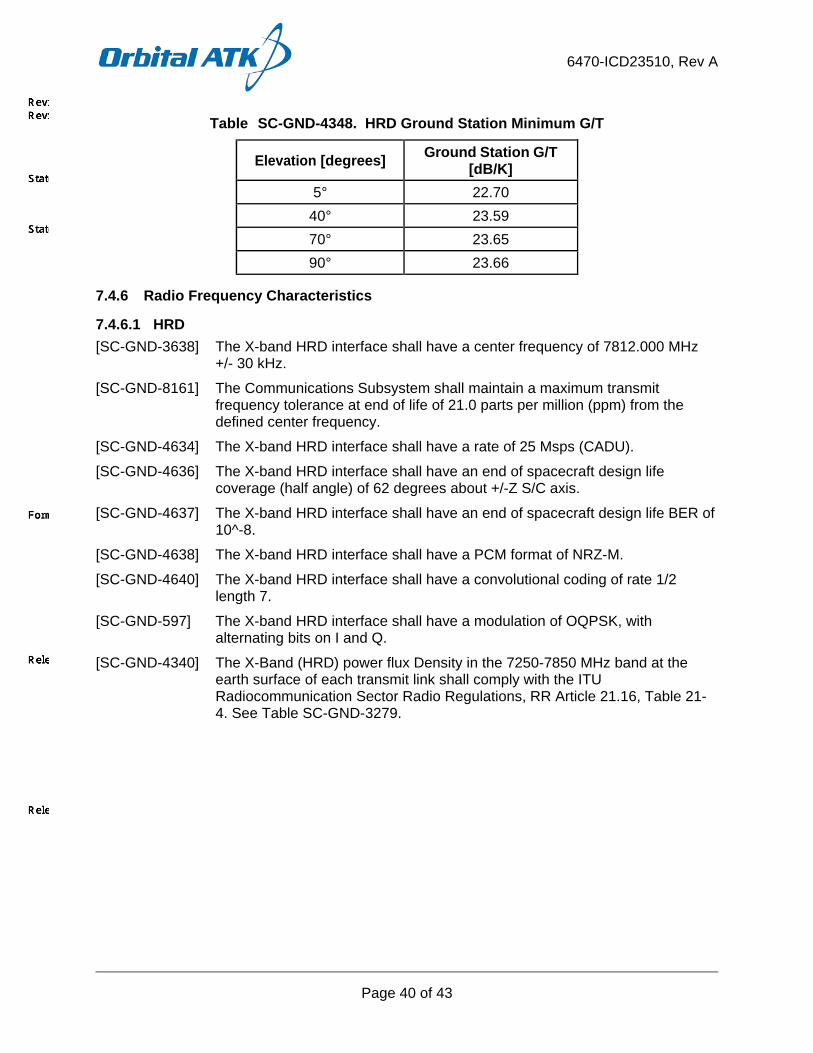
6470-ICD23510, Rev A
Page 40 of 43
Table SC-GND-4348. HRD Ground Station Minimum G/T
Elevation [degrees] Ground Station G/T [dB/K]
5° 22.70 40° 23.59 70° 23.65 90° 23.66
7.4.6 Radio Frequency Characteristics
7.4.6.1 HRD [SC-GND-3638] The X-band HRD interface shall have a center frequency of 7812.000 MHz
+/- 30 kHz.
[SC-GND-8161] The Communications Subsystem shall maintain a maximum transmit frequency tolerance at end of life of 21.0 parts per million (ppm) from the defined center frequency.
[SC-GND-4634] The X-band HRD interface shall have a rate of 25 Msps (CADU).
[SC-GND-4636] The X-band HRD interface shall have an end of spacecraft design life coverage (half angle) of 62 degrees about +/-Z S/C axis.
[SC-GND-4637] The X-band HRD interface shall have an end of spacecraft design life BER of 10^-8.
[SC-GND-4638] The X-band HRD interface shall have a PCM format of NRZ-M.
[SC-GND-4640] The X-band HRD interface shall have a convolutional coding of rate 1/2 length 7.
[SC-GND-597] The X-band HRD interface shall have a modulation of OQPSK, with alternating bits on I and Q.
[SC-GND-4340] The X-Band (HRD) power flux Density in the 7250-7850 MHz band at the earth surface of each transmit link shall comply with the ITU Radiocommunication Sector Radio Regulations, RR Article 21.16, Table 21-4. See Table SC-GND-3279.

6470-ICD23510, Rev A
Page 41 of 43
Table SC-GND-3279. HRD (X-Band) Maximum Power Flux Density Levels
PFD in dB (Watts/M^2/4 kHz) Signal Arrival Angle -152 0 < Theta < 5 degrees
-152 + 0.5 (Theta -5) 5 < Theta < 25 degrees -142 25<Theta < 90 degrees
Reference bandwidth 4 KHz Note: Where PFD levels are specified in units of dB (watts/square meter/4 kHz) and Theta is the signal arrival angle above the horizontal plane at the Earths surface.
8 OPERATIONS In addition to the information contained in this section, further details that meet the intent of the DID requirements are provided within OPS-4 and OPS-9.
8.1 Operating Modes and Command Events The Observatory modes and transitions are shown in Figure SC-GND-4188.
Figure SC-GND-4188. Satellite Modes and Transitions
Autonomous transitions occur via RTS commands in response to fault checks of various types, or sep detection for Launch – Safe transition.
The satellite also has an “OFF” Mode and I&T Mode, which are ground test only modes and are defined in the Satellite Performance Specification (SPS) (6470-PF23200) [CDRL SE-1].
8.1.1 Launch, Early Orbit, and Anomaly (LEO&A)
8.1.1.1 S-Band Operations This section is not applicable to the Satellite HRD to DBS RF ICD.
8.1.1.2 Ka-Band Operations This section is not applicable to the Satellite HRD to DBS RF ICD.
LAUNCH
SPACECRAFT SAFE
-Sun-pointing Safe-Earth-pointing Safe
ENGINEERING-Orbit Adjust/Collision Avoidance-Instrument Calibration Maneuvers
DE-ORBIT
SCIENCE OPERATIONS
Manually Commanded Transition
Manual command or Autonomous Transition

6470-ICD23510, Rev A
Page 42 of 43
8.1.1.3 X-Band Operations During the first week, all subsystems and components will be powered on and initialized. X-band communications will begin once ACS is configured in Earth-Point mode. Once the Satellite is placed into Science Mode, HRD data are broadcast continuously in real-time to X-band ground terminals. For additional information regarding X-band operations during LEO&A, refer to the JPSS Spacecraft Concept of Operations (6470-DG31100) [CDRL OPS-7].
8.1.2 Routine Operations Routine command operations include realtime commanding and stored command sequence uploads. Routine telemetry operations include monitoring realtime telemetry, SSOH data, and Attitude & Ephemeris Packet data dumps from the FMC.
8.1.2.1 Orbit Adjust Engineering This mode is used for orbit adjustments and maintenance.
8.1.2.2 Instrument Calibration Modes
8.1.2.3 Science Operations Mode This mode is the nominal nadir pointing mission mode and includes daily operations, periodic operations, and infrequent operations. Realtime operations include execution of stored commands (ATS / RTS) and playback of stored telemetry data (SMD, RAM SSOH). Real time operations also include management of communications links including S-band, Ka-band, and X-band links. Periodic operations include orbit maintenance and calibrations.
8.1.2.4 S-Band Operations This section is not applicable to the Satellite HRD to DBS RF ICD.
8.1.2.5 X-Band Operations HRD is provided to the direct readout community by an X-band (7812 MHz) 25 Mbps downlink. HRD data are broadcast continuously in real-time to X-band ground terminals when the Satellite is in Science Mode. For additional information regarding X-band routine operations, refer to the JPSS Spacecraft Concept of Operations (6470-DG31100) [CDRL OPS-7].
8.1.2.6 Ka-Band Operations This section is not applicable to the Satellite HRD to DBS RF ICD.
8.1.2.7 De-orbit Mode This mode is used for de-orbiting the Satellite at the end of life. Spacecraft propulsion and ACS subsystems are designed for de-orbit operations. The controlled burn plan will include a de-orbit command sequence to be loaded into stored command sequences on-board. Burns can be monitored via TDRSS, as available. The de-orbit timeline will cover days, hours, minutes prior to, and through the de-orbit event. The propulsion Subsystem fuel budget includes an allocation for the de-orbit event. De-orbit event planning inputs are fed into the overall decommissioning plan.
8.1.3 Contingency Operations Contingency operations include autonomous onboard safing and use of contingency procedures to recover from an on-orbit fault.
6470-ICD23510, Rev A
Page 43 of 43
8.1.3.1 Sun pointing Safe Mode Most anomalies force the Satellite into this mode. When the satellite is in this mode, SADA no longer rotates, and the satellite attitude maintains Solar Array Normal towards the sun vector.
8.1.3.2 Earth pointing Safe Mode Minor anomalies result in Earth Point Safehold. This mode is similar to nominal Science Operations Mode, but not all performance requirements will be met in this mode, depending on the failure.
8.1.3.3 S-Band Contingency Operations This section is not applicable to the Satellite HRD to DBS RF ICD.
8.1.3.4 X-Band Contingency Operations HRD data are not broadcast when the Satellite is in Safe Mode. For additional information regarding X-band contingency operations, refer to the JPSS Spacecraft Concept of Operations (6470-DG31100) [CDRL OPS-7].
8.2 Approach for Maneuver Planning and Execution The Satellite executes orbit-adjust maneuvers for Drag Make-up (DMU), collision avoidance, and end-of-life deorbit. The Satellite also performs routine maintenance activities such as orbit adjust maneuvers and instrument sensor calibration maneuvers. The Satellite's Attitude Control System (ACS) performs calibration maneuvers by orienting the satellite to meet the required attitude. TDRSS will provide support for LEO&A, orbit maneuvers, contingency and SMD operations. Orbit Adjust Modes are used to execute orbit maneuvers for Drag Make-up (DMU), collision avoidance, and end-of-life deorbit.
8.2.1 S-Band Operations This section is not applicable to the Satellite HRD to DBS RF ICD.
8.2.2 X-Band Operations Because Satellite maneuvers are executed when in SC Orbit Adjust Modes, X-band HRD data are not broadcast during these events. For additional information regarding maneuver planning and execution and X-band operations, refer to the JPSS Spacecraft Concept of Operations (6470-DG31100) [CDRL OPS-7].
6470-ICD23510, Rev A
Page A-1 of 9
APPENDIX A.
VERIFICATION CROSS REFERENCE MATRIX (VCRM)
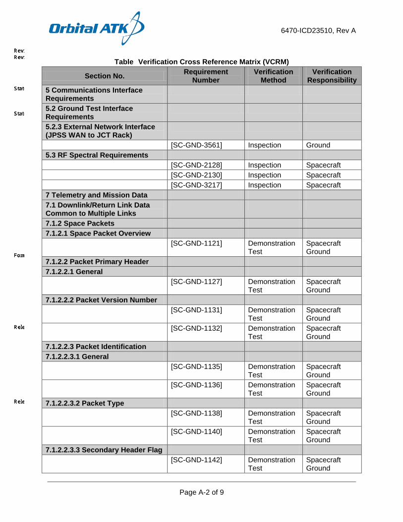
6470-ICD23510, Rev A
Page A-2 of 9
Table Verification Cross Reference Matrix (VCRM)
Section No. Requirement Number
Verification Method
Verification Responsibility
5 Communications Interface Requirements
5.2 Ground Test Interface Requirements
5.2.3 External Network Interface (JPSS WAN to JCT Rack)
[SC-GND-3561] Inspection Ground 5.3 RF Spectral Requirements [SC-GND-2128] Inspection Spacecraft [SC-GND-2130] Inspection Spacecraft [SC-GND-3217] Inspection Spacecraft 7 Telemetry and Mission Data 7.1 Downlink/Return Link Data Common to Multiple Links
7.1.2 Space Packets 7.1.2.1 Space Packet Overview [SC-GND-1121] Demonstration
Test Spacecraft Ground
7.1.2.2 Packet Primary Header 7.1.2.2.1 General [SC-GND-1127] Demonstration
Test Spacecraft Ground
7.1.2.2.2 Packet Version Number [SC-GND-1131] Demonstration
Test Spacecraft Ground
[SC-GND-1132] Demonstration Test
Spacecraft Ground
7.1.2.2.3 Packet Identification 7.1.2.2.3.1 General [SC-GND-1135] Demonstration
Test Spacecraft Ground
[SC-GND-1136] Demonstration Test
Spacecraft Ground
7.1.2.2.3.2 Packet Type [SC-GND-1138] Demonstration
Test Spacecraft Ground
[SC-GND-1140] Demonstration Test
Spacecraft Ground
7.1.2.2.3.3 Secondary Header Flag [SC-GND-1142] Demonstration
Test Spacecraft Ground
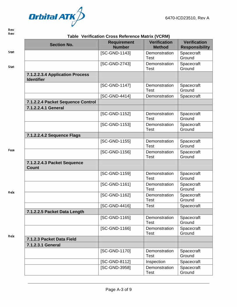
6470-ICD23510, Rev A
Page A-3 of 9
Table Verification Cross Reference Matrix (VCRM)
Section No. Requirement Number
Verification Method
Verification Responsibility
[SC-GND-1143] Demonstration Test
Spacecraft Ground
[SC-GND-2743] Demonstration Test
Spacecraft Ground
7.1.2.2.3.4 Application Process Identifier
[SC-GND-1147] Demonstration Test
Spacecraft Ground
[SC-GND-4414] Demonstration Spacecraft 7.1.2.2.4 Packet Sequence Control 7.1.2.2.4.1 General [SC-GND-1152] Demonstration
Test Spacecraft Ground
[SC-GND-1153] Demonstration Test
Spacecraft Ground
7.1.2.2.4.2 Sequence Flags [SC-GND-1155] Demonstration
Test Spacecraft Ground
[SC-GND-1156] Demonstration Test
Spacecraft Ground
7.1.2.2.4.3 Packet Sequence Count
[SC-GND-1159] Demonstration Test
Spacecraft Ground
[SC-GND-1161] Demonstration Test
Spacecraft Ground
[SC-GND-1162] Demonstration Test
Spacecraft Ground
[SC-GND-4416] Test Spacecraft 7.1.2.2.5 Packet Data Length [SC-GND-1165] Demonstration
Test Spacecraft Ground
[SC-GND-1166] Demonstration Test
Spacecraft Ground
7.1.2.3 Packet Data Field 7.1.2.3.1 General [SC-GND-1170] Demonstration
Test Spacecraft Ground
[SC-GND-8112] Inspection Spacecraft [SC-GND-3958] Demonstration
Test Spacecraft Ground

6470-ICD23510, Rev A
Page A-4 of 9
Table Verification Cross Reference Matrix (VCRM)
Section No. Requirement Number
Verification Method
Verification Responsibility
7.1.2.3.2 Packet Secondary Header
7.1.2.3.2.1 General [SC-GND-1174] Demonstration
Test Spacecraft Ground
[SC-GND-2745] Demonstration Test
Spacecraft Ground
7.1.2.3.2.2 Time Code Field [SC-GND-3904] Inspection Spacecraft [SC-GND-4403] Demonstration Spacecraft [SC-GND-4584] Demonstration Spacecraft [SC-GND-3971] Demonstration
Test Spacecraft Ground
[SC-GND-4089] Demonstration Test
Spacecraft Ground
[SC-GND-3341] Demonstration Test
Spacecraft Ground
[SC-GND-3972] Demonstration Test
Spacecraft Ground
[SC-GND-4090] Demonstration Test
Spacecraft Ground
[SC-GND-4430] Demonstration Spacecraft [SC-GND-1183] Demonstration
Test Spacecraft Ground
[SC-GND-2873] Demonstration Test
Spacecraft Ground
[SC-GND-3343] Demonstration Test
Spacecraft Ground
[SC-GND-2874] Demonstration Test
Spacecraft Ground
7.1.2.3.2.3 Number of Packet Segments
[SC-GND-4418] Test Spacecraft [SC-GND-4419] Demonstration Spacecraft 7.1.2.4 User Data Field [SC-GND-1190] Demonstration
Test Spacecraft Ground
[SC-GND-1192] Demonstration Test
Spacecraft Ground
[SC-GND-8113] Inspection Spacecraft [SC-GND-8115] Inspection Spacecraft

6470-ICD23510, Rev A
Page A-5 of 9
Table Verification Cross Reference Matrix (VCRM)
Section No. Requirement Number
Verification Method
Verification Responsibility
[SC-GND-2897] Demonstration Test
Spacecraft Ground
7.1.3 Transfer Frame [SC-GND-639] Demonstration Spacecraft
Ground 7.1.3.1 Transfer Frame Primary Header
7.1.3.1.1 General [SC-GND-644] Demonstration Spacecraft
Ground 7.1.3.1.2 Master Channel Identifier [SC-GND-664] Demonstration Spacecraft
Ground [SC-GND-665] Demonstration Spacecraft
Ground 7.1.3.1.2.2 Transfer Frame Version Number
[SC-GND-666] Demonstration Spacecraft Ground
[SC-GND-667] Demonstration Spacecraft Ground
7.1.3.1.2.3 Spacecraft ID [SC-GND-668] Demonstration Spacecraft
Ground [SC-GND-671] Demonstration Spacecraft
Ground 7.1.3.1.3 Virtual Channel ID [SC-GND-672] Demonstration
Test Spacecraft Ground
7.1.3.1.4 Virtual Channel Frame Count
[SC-GND-675] Demonstration Spacecraft Ground
[SC-GND-676] Demonstration Spacecraft Ground
7.1.3.1.5 Signaling Field 7.1.3.1.5.1 General [SC-GND-678] Demonstration Spacecraft
Ground [SC-GND-680] Demonstration Spacecraft
Ground

6470-ICD23510, Rev A
Page A-6 of 9
Table Verification Cross Reference Matrix (VCRM)
Section No. Requirement Number
Verification Method
Verification Responsibility
7.1.3.1.5.2 Replay Flag [SC-GND-681] Demonstration Spacecraft
Ground [SC-GND-683] Demonstration Spacecraft
Ground 7.1.3.1.5.3 VC Frame Count Cycle Usage Flag
[SC-GND-684] Demonstration Spacecraft Ground
7.1.3.1.5.4 Reserved Spare [SC-GND-686] Demonstration Spacecraft
Ground [SC-GND-687] Demonstration Spacecraft
Ground 7.1.3.1.5.5 VC Frame Count Cycle [SC-GND-2879] Demonstration Spacecraft
Ground 7.1.3.3 Transfer Frame Data Field 7.1.3.3.1 Overview [SC-GND-708] Demonstration Spacecraft
Ground [SC-GND-709] Demonstration
Test Spacecraft Ground
[SC-GND-710] Demonstration Test
Spacecraft Ground
[SC-GND-711] Demonstration Spacecraft Ground
[SC-GND-712] Demonstration Spacecraft Ground
[SC-GND-2886] Demonstration Spacecraft Ground
[SC-GND-2887] Test Spacecraft Ground
7.1.3.3.2 Multiplexing Protocol Data Unit
7.1.3.3.2.1 Overview [SC-GND-715] Demonstration Spacecraft
Ground [SC-GND-716] Demonstration
Test Spacecraft Ground
[SC-GND-714] Demonstration Test
Spacecraft Ground
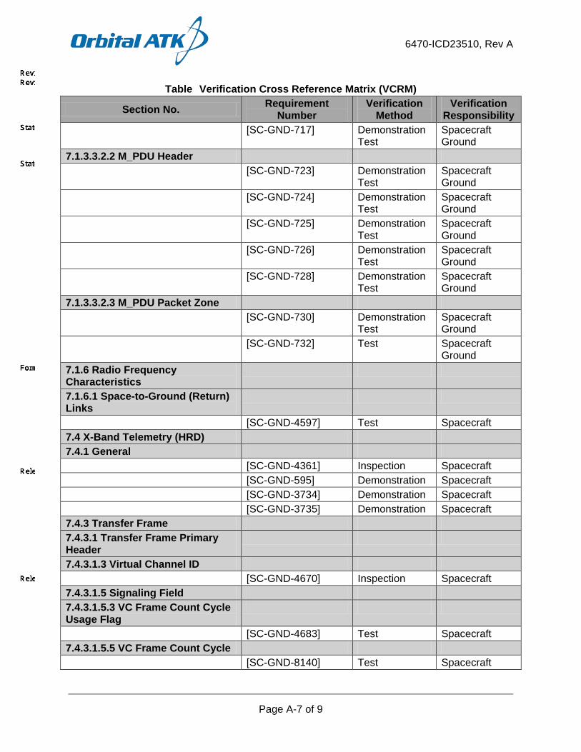
6470-ICD23510, Rev A
Page A-7 of 9
Table Verification Cross Reference Matrix (VCRM)
Section No. Requirement Number
Verification Method
Verification Responsibility
[SC-GND-717] Demonstration Test
Spacecraft Ground
7.1.3.3.2.2 M_PDU Header [SC-GND-723] Demonstration
Test Spacecraft Ground
[SC-GND-724] Demonstration Test
Spacecraft Ground
[SC-GND-725] Demonstration Test
Spacecraft Ground
[SC-GND-726] Demonstration Test
Spacecraft Ground
[SC-GND-728] Demonstration Test
Spacecraft Ground
7.1.3.3.2.3 M_PDU Packet Zone [SC-GND-730] Demonstration
Test Spacecraft Ground
[SC-GND-732] Test Spacecraft Ground
7.1.6 Radio Frequency Characteristics
7.1.6.1 Space-to-Ground (Return) Links
[SC-GND-4597] Test Spacecraft 7.4 X-Band Telemetry (HRD) 7.4.1 General [SC-GND-4361] Inspection Spacecraft [SC-GND-595] Demonstration Spacecraft [SC-GND-3734] Demonstration Spacecraft [SC-GND-3735] Demonstration Spacecraft 7.4.3 Transfer Frame 7.4.3.1 Transfer Frame Primary Header
7.4.3.1.3 Virtual Channel ID [SC-GND-4670] Inspection Spacecraft 7.4.3.1.5 Signaling Field 7.4.3.1.5.3 VC Frame Count Cycle Usage Flag
[SC-GND-4683] Test Spacecraft 7.4.3.1.5.5 VC Frame Count Cycle [SC-GND-8140] Test Spacecraft
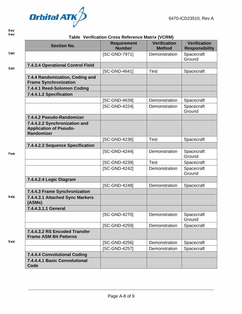
6470-ICD23510, Rev A
Page A-8 of 9
Table Verification Cross Reference Matrix (VCRM)
Section No. Requirement Number
Verification Method
Verification Responsibility
[SC-GND-7971] Demonstration Spacecraft Ground
7.4.3.4 Operational Control Field [SC-GND-4641] Test Spacecraft 7.4.4 Randomization, Coding and Frame Synchronization
7.4.4.1 Reed-Solomon Coding 7.4.4.1.2 Specification [SC-GND-4639] Demonstration Spacecraft [SC-GND-4224] Demonstration Spacecraft
Ground 7.4.4.2 Pseudo-Randomizer 7.4.4.2.2 Synchronization and Application of Pseudo-Randomizer
[SC-GND-4236] Test Spacecraft 7.4.4.2.3 Sequence Specification [SC-GND-4244] Demonstration Spacecraft
Ground [SC-GND-4239] Test Spacecraft [SC-GND-4242] Demonstration Spacecraft
Ground 7.4.4.2.4 Logic Diagram [SC-GND-4248] Demonstration Spacecraft 7.4.4.3 Frame Synchronization 7.4.4.3.1 Attached Sync Markers (ASMs)
7.4.4.3.1.1 General [SC-GND-4270] Demonstration Spacecraft
Ground [SC-GND-4259] Demonstration Spacecraft 7.4.4.3.2 RS Encoded Transfer Frame ASM Bit Patterns
[SC-GND-4256] Demonstration Spacecraft [SC-GND-4257] Demonstration Spacecraft 7.4.4.4 Convolutional Coding 7.4.4.4.1 Basic Convolutional Code

6470-ICD23510, Rev A
Page A-9 of 9
Table Verification Cross Reference Matrix (VCRM)
Section No. Requirement Number
Verification Method
Verification Responsibility
7.4.4.4.1.2 Basic Convolutional Code Specification
[SC-GND-4267] Demonstration Spacecraft Ground
7.4.5 Modulation 7.4.5.4 Modulation Performance [SC-GND-8183] Analysis Spacecraft [SC-GND-4292] Analysis Spacecraft
Ground [SC-GND-4293] Test Spacecraft
Ground [SC-GND-8184] Analysis Spacecraft [SC-GND-8185] Analysis Spacecraft [SC-GND-8187] Analysis Spacecraft [SC-GND-8188] Analysis Spacecraft [SC-GND-8189] Analysis Spacecraft 7.4.5.5 Maximum Permissible Spurious Emission
[SC-GND-4295] Demonstration Spacecraft Ground
7.4.5.6 Telemetry Symbol Rate Stability in Suppressed Carrier Telemetry Systems
[SC-GND-4297] Test Spacecraft Ground
7.4.6 Radio Frequency Characteristics
7.4.6.1 HRD [SC-GND-3638] Analysis
Test Spacecraft
[SC-GND-8161] Analysis Spacecraft [SC-GND-4634] Demonstration Spacecraft [SC-GND-4636] Analysis Spacecraft [SC-GND-4637] Analysis Spacecraft [SC-GND-4638] Test Spacecraft [SC-GND-4640] Demonstration Spacecraft [SC-GND-597] Demonstration Spacecraft [SC-GND-4340] Inspection Spacecraft
6470-ICD23510, Rev A
Page B-1 of 2
APPENDIX B.
TBX MATRIX

6470-ICD23510, Rev A
Page B-2 of 2
None