joint transmission planning base case preparation process · caiso and sce joint transmission...
TRANSCRIPT

CAISO and SCE Joint Transmission Planning Base Case Preparation Process
California Independent System Operator &
Southern California Edison
Joint Transmission Planning Base Case Preparation Process
NERC Reliability Standard MOD-032-1
Version 1.2
August 31, 2017
CAISO and SCE Joint Transmission Planning Base Case Preparation Process
INTENTIONALLY LEFT BLANK

CAISO and SCE Joint Transmission Planning Base Case Preparation Process
Page | i
Table of Contents
I. Introduction ............................................................................................................................. 1
II. SCE’s Master Base Cases .......................................................................................................... 2
A. Data Requirements .............................................................................................................. 2
B. Steady State Data ................................................................................................................. 3
C. Dynamic Data ....................................................................................................................... 4
D. Short Circuit Duty Data ........................................................................................................ 4
E. Generator Owner Procedures .............................................................................................. 4
F. Base Case Schedule to Submit Data to WECC ..................................................................... 4
III. Roles and Responsibilities ....................................................................................................... 5
A. Master Base Case Development .......................................................................................... 5
B. Generation Interconnection Planning’s (GIP) Base Case Roles and Responsibilities: ......... 8
1. Generation Interconnection Planning Base Cases ........................................................ 8
2. New Generation and Interconnection Facilities: .......................................................... 9
3. Network Upgrades or SPS for Interconnecting Generators ......................................... 9
C. Reliability Planning’s (RP) Base Case Roles and Responsibilities: ...................................... 10
1. Prepare and Update Transmission Planning’s ATRA Base Case ................................. 10
2. Reliability Planning’s ATRA Base Cases: ...................................................................... 10
D. Intertie Planning’s (IP) Base Case Roles and Responsibilities: ........................................... 11
E. CAISO’S Roles and Responsibilities ................................................................................... 11
F. PTO or non-PTO Roles and Responsibilities ....................................................................... 12
1. Initial Base Case Data Submittal ................................................................................. 12
2. WECC’s Base Cases for Base Case Review .................................................................. 13
G. Base Case Submittals to WECC .......................................................................................... 13
IV. Revision History ..................................................................................................................... 16
Appendices Appendix A DATA PREPARATION AND DATA VALIDATION .......................................................... 17
Appendix B WECC BASE CASE PREPARATION ............................................................................... 51
A. WECC Initial Base Case Compilation .................................................................................. 51
B. WECC Final Base Case Review ........................................................................................... 53
C. SCE Base Case Retention Requirements ............................................................................ 54
Appendix C WECC Base Case Development Checklist ................................................................. 55
Appendix D CAISO sign-off sheet for WECC Base Case review .................................................... 61
Appendix E Anchor Data Set (ADS) .............................................................................................. 62
CAISO and SCE Joint Transmission Planning Base Case Preparation Process
Page | ii
CAISO and SCE Joint Transmission Planning Base Case Preparation Process
Page | 1
I. Introduction
The purpose of the Transmission Planning Base Case Preparation Process (Process) is six fold. The first, as required by NERC Reliability Standard MOD-032 (MOD-032), Requirement 1, is to provide a jointly developed process for California Independent System Operator’s (CAISO) (as Planning Coordinator (PC) and Balancing Authority (BA)) and Southern California Edison’s (SCE) steady-state, dynamics, and short circuit modeling data requirements and reporting procedures for the PC planning area. Second, this Process will demonstrate and help support how CAISO, SCE, and Participating Transmission Owner’s (PTO1), including: Resource Planners, Transmission Owners, Transmission Planners, and Transmission Service Providers meet MOD-032 and WECC’s Data Preparation Manual requirements. The CAISO is the PC and BA for PTOs and Transmission Planners located in area 24 of the WECC base cases, which includes, but not limited to: SCE, MWD, City of Anaheim, City of Azusa, City of Banning, City of Colton, City of Pasadena, City of Riverside, and City of Vernon. This process was developed in accordance with MOD-032, Requirement 1, as follows:
Provide guidance to model the data listed in Attachment 1 of MOD-032.
Provide specifications of the following items consistent with procedures for building the Interconnection-wide case(s): o Data format; o Level of detail to which equipment shall be modeled; o Case types or scenarios to be modeled; and o A schedule for submission of data at least once every 13 calendar months.
Provide specifications for distribution or posting of the data requirements and reporting
Provide procedures so that they are available to those entities responsible for providing the data.
Third, as required by MOD-032, Requirement 2, this process provides guidance to: each BA (including non-PTO entities in area 24 of the WECC base cases), Generator Owners, Load Serving Entities, Resource Planners, Transmission Owners, and Transmission Service Providers that shall provide steady-state, dynamics, and short circuit modeling data to its Transmission Planner(s) and Planning Coordinator(s) according to the data requirements and reporting procedures developed by its Planning Coordinator and Transmission Planner in Requirement R1.
1 Per CAISO, a PTO is defined as a Transmission Owner that enters into a Transmission Control Agreement (TCA)
with CAISO and places its transmission assets and Entitlements under CAISO’s operational control in accordance with the agreement. For the latest “List of Participating Transmission Owners”, refer to the CAISO’s public website.
CAISO and SCE Joint Transmission Planning Base Case Preparation Process
Page | 2
Fourth, as required by MOD-032, Requirement 3, upon receipt of written notification from its Planning Coordinator or Transmission Planner regarding technical concerns with the data submitted under Requirement R2, including the technical basis or reason for the technical concerns, each notified Balancing Authority, Generator Owner, Load Serving Entity, Resource Planner, Transmission Owner, or Transmission Service Provider shall respond to the notifying Planning Coordinator or Transmission Planner as follows:
Provide either updated data or an explanation with a technical basis for maintaining the current data;
Provide the response within 90 calendar days of receipt, unless a longer time period is agreed upon by the notifying Planning Coordinator or Transmission Planner.
Fifth, as required by MOD-032, Requirement 4, CAISO or its designee shall make available models for its planning area reflecting data provided to it under Requirement R2 to WECC (Electric Reliability Organization (ERO) designee) to support creation of the Interconnection-wide case(s) that includes the CAISO’s planning in area 24 of the WECC base cases). Sixth, this Process establishes consistency amongst various CAISO and SCE Planning base cases utilized for compliance with NERC Standards applicable to Planning Coordinators and Transmission Planners and includes controls to ensure data accuracy and fidelity to base case objectives by use of checklists and formal reviews. The CAISO shall make this base case process available to all the PTOs and non-PTOs in area 24 of the WECC base cases by email or posting on CAISO’s public website.
II. SCE’s Master Base Cases
Data Requirements (MOD-032, R1, R2, & R3):
A. Data Requirements
This section provides the data format and content requirements for development of SCE’s master base cases. Refer to Appendix A, Data Preparation and Data Validation, and WECC’s latest approved DPM for further detailed modeling requirements. PTOs and non-PTOs, including Generator Owner, Load Serving Entity, Resource Planner, Transmission Owner, or Transmission Service Provider shall provide their data to SCE and CAISO to be modeled into WECC’s base cases in accordance with the WECC Base Case Compilation Schedule or revised schedule/dates as communicated by WECC. WECC will send request letters to PTOs and non-PTOs who are on WECC’s Technical Studies Subcommittee (TSS) distribution list. The aforementioned shall provide their data as specified in the below data requirements that is consistent with the interconnection-wide process and in accordance with MOD-032. Refer to Appendix A and WECC’s latest approved DPM for further details. This data will be incorporated

CAISO and SCE Joint Transmission Planning Base Case Preparation Process
Page | 3
into SCE’s master base cases, which will be used by CAISO and SCE transmission planning groups to develop additional base cases for their respective studies.
These requirements are for establishing consistent system models amongst SCE’s Transmission Planning groups and CAISO to support analyses of CAISO’s footprint, SCE’s transmission system, and WECC’s interconnection-wide transmission system, and they help avoid potential solution problems. The following guidelines shall be followed to meet the NERC Reliability Standard, MOD-032. Appendix A and WECC’s latest approved DPM address each data type requirements.
If the Short Circuit Duty (SCD) data format is from a program other than PSLF or PowerWorld, then this data shall be provided to SCE in the separate format (e.g., Aspen or Cape).
Upon request, SCE shall provide the SCD data within an agreed upon timeframe for the purposes consistent with the interconnection wide process.
B. Steady State Data
Transmission Facilities:
With the exception of collector-based generation such as wind and solar, all Bulk Electric System elements, as presently defined by NERC, within SCE’s system shall be represented in SCE base cases without equivalency.
The facilities are expected to be in-service in the month and year represented by the case.
ISO approved facilities that are specifically needed to mitigate conditions which exceeds transmission planning criteria and NERC reliability standards.
Existing transmission facilities.
If necessary, Non-Bulk Electric System elements must follow the same submittal requirements for the Bulk Electric System elements.
o Any equivalency of non-Bulk Electric System elements shall be modeled to yield similar results as a full representation in both static and dynamic analysis
o Non-Bulk Electric System Generation shall, at a minimum include, but are not limited to:
Facilities with connected individual generation resources ≥ 10 MVA or aggregate generation resources ≥ 20MVA
Facilities with connected reactive resources ≥ 10 MVAR
The data requirements should be consistent with WECC’s latest approved DPM and NERC Reliability Standard MOD-032. Refer to Appendix A and WECC’s latest approved DPM for further requirements.

CAISO and SCE Joint Transmission Planning Base Case Preparation Process
Page | 4
C. Dynamic Data
To provide consistency in data submittals and help avoid potential simulation problems, the guidelines of WECC’s latest approved DPM and Appendix A shall be followed prior to each submittal. In all cases, dynamic data must match with steady-state data provided for each SCE base case (i.e., bus name and number, voltage, and MVA, must be the same for both power flow and dynamic modeling).
D. Short Circuit Duty Data
Short circuit data is necessary to perform a several studies such as breaker duty evaluation and relay coordination. The necessary data includes the zero, positive, and negative sequence data of transmission lines but also includes but not limited to the generator characteristics and transformer winding connections.
a. Positive Sequence b. Negative Sequence c. Zero Sequence d. Mutual Coupling Line Impedance e. Transformer Winding Connections
E. Generator Owner Procedures
Any Generator Owner within area 24 of the WECC base cases shall provide modeling data in accordance with NERC Reliability Standards, the WECC Data Preparation Manual, and the WECC Generating Unit Model Validation Policy to SCE and the CAISO according to the periodicity in the NERC Reliability Standards (MODs 025, 026, & 027 & PRCs 19 & 24) and WECC Generating Unit Model Validation Policy.
Upon receipt of this data from generator owners and after usability is confirmed by SCE, these models will be modeled in both the power flow base cases and WECC’s dynamic data file, as needed.
Data Requirements (MOD-032, R4):
F. Base Case Schedule to Submit Data to WECC
SCE, PTOs, and non-PTOs located in area 24 of the WECC base cases will coordinate to develop a base case that represents each entities system in a WECC full-loop base case which supports the creation of the Interconnection-wide cases(s). Each PTO and non-PTO located in area 24 of the WECC base cases, including: Resource Planners, Transmission Owners, Transmission Planners, and Transmission Service Providers shall submit their data to SCE and CAISO in accordance with the WECC Base Case Compilation Schedule or revised schedule/dates as communicated by WECC; that is if changes are made to their base case models. Upon receipt from PTOs’ and non-PTOs’ data in area 24 of the WECC base cases in CAISO planning area, SCE
CAISO and SCE Joint Transmission Planning Base Case Preparation Process
Page | 5
will model the data and submit a full-loop base that incorporates SCE’s, PTOs’ and non-PTOs’ data to WECC. These base cases will be submitted to WECC and CAISO in accordance with the WECC Base Case Compilation Schedule or revised schedule/dates as communicated by WECC. When an issue of submittal timing warrants extending the deadline, SCE may modify the due dates, not to exceed 15 calendar days, by an agreed upon extension between the Southern California Area Coordinator, WECC, or the CAISO.
III. Roles and Responsibilities
A. Master Base Case Development
The master base case, also known as SCE’s WECC Master Base Cases, shall be used as the starting base case for each WECC and ATRA base cases. SCE develops and maintains three WECC Master Base Cases, a 1 year out, 5 year out, and 10-year out case. The following provides the process to develop the common base case:
1. Annually, SCE’s Reliability Planning (RP) shall compare an approved WECC base cases with SCE’s Master base cases to develop the ATRA bases cases.
2. Any updates to the ATRA cases shall be coordinated between IP and GIP for any necessary changes.
3. RP shall send the updated ATRA base cases to the WECC base case preparer (Preparer).
4. The Preparer shall then compare the updated ATRA base cases with SCE’s latest WECC Master Base Cases and resolve any discrepancies between the cases.
5. Any discrepancies resolved between RP and Preparer will be incorporated into the ATRA base cases and SCE’s WECC Master Base Cases, based on the month and year represented by the cases.
6. The updated SCE WECC master base case shall be posted on the transmission planning’s share drive.
7. The Preparer shall maintain SCE’s WECC master base cases throughout the year.
8. The Preparer shall maintain a log file of all changes to the master base cases and will provide it to the ISO when requested.
The WECC master base cases shall be evaluated and validated on an annual basis for SCE owned facilities. This shall include, but not limited to:
- Latest transmission system topology - Transmission line and transformer Impedances - Transmission line and transformer facility Ratings - Dynamic models - Latest generation interconnection information - WECC’s Rep Log Items

CAISO and SCE Joint Transmission Planning Base Case Preparation Process
Page | 6
Refer to Appendix A “Data Requirements and Data Validation” for detailed data modeling requirements. These data requirements were extracted from the current WECC DPM. The tables in this appendix provides power flow and dynamic data requirements.
Roles and Responsibilities
Responsible entities Roles
Intertie Planning Develop master base cases.
Maintain master base cases.
Incorporate project files developed by Transmission Planning groups on an as needed bases.*
Notify RP and provide change files for CAISO identified base case changes during WECC base case review process.
Generation Interconnection Planning Prepare Generation Interconnection Studies base cases from the ATRA base cases.
Coordinate any base case changes with RP which in turn will coordinate with Intertie Planning as part of their process.
Develop and provide project files, including powerflow and dynamic data, for any sponsored projects that will be modeled in the master base cases to RP and IP Preparer.
Notify IP and provide change files for CAISO identified base case changes during Generation Interconnection process.
Reliability Planning Annually prepare the ATRA base cases.
Provide the ATRA base cases to the Preparer.
Notify IP and GIP of any changes to the ATRA base cases and provide a change file to the Preparer in an EPC or EPCL format.
Develop and provide project files for approved CAISO transmission projects to the Preparer.
Notify IP and provide change files for CAISO identified base case changes during TPP process.
* Project files for incorporating into the master base cases shall follow the requirements as identified in Appendix A.

CAISO and SCE Joint Transmission Planning Base Case Preparation Process
Page | 7
Transmission Planning Modeling Assumptions
Base Case Models Intertie Planning Reliability Planning Generation
Interconnection Planning
CAISO TPP
Generation Model generation in-service, under construction, or on an as needed bases
Per CAISO Study TPP Study Plan Populate PMAX2 with NQC
Consistent with all applicable Interconnection Procedures
Per CAISO TPP Study Plan (generally the same as Reliability Planning)
Transmission Facilities
Including, but not limited to: Existing CAISO controlled Facilities CAISO approved transmission projects
Including, but not limited to: Existing CAISO controlled facilities CAISO approved transmission projects
Consistent with all applicable Interconnection Procedures
Per CAISO TPP Study Plan (generally the same as Reliability Planning)
Load Forecast CEC 1-in-2 year load forecast.
CEC Forecast 1 in 10 year load forecast for peak cases, off-peak cases varies Explicit additional achievable energy efficiency load models Demand Response (voluntary load shed)
Based on ATRA base case utilized as directed by CAISO.
Per CAISO TPP Study Plan (generally the same as Reliability Planning)
CAISO and SCE Joint Transmission Planning Base Case Preparation Process
Page | 8
Base Case Models Intertie Planning Reliability Planning Generation
Interconnection Planning
CAISO TPP
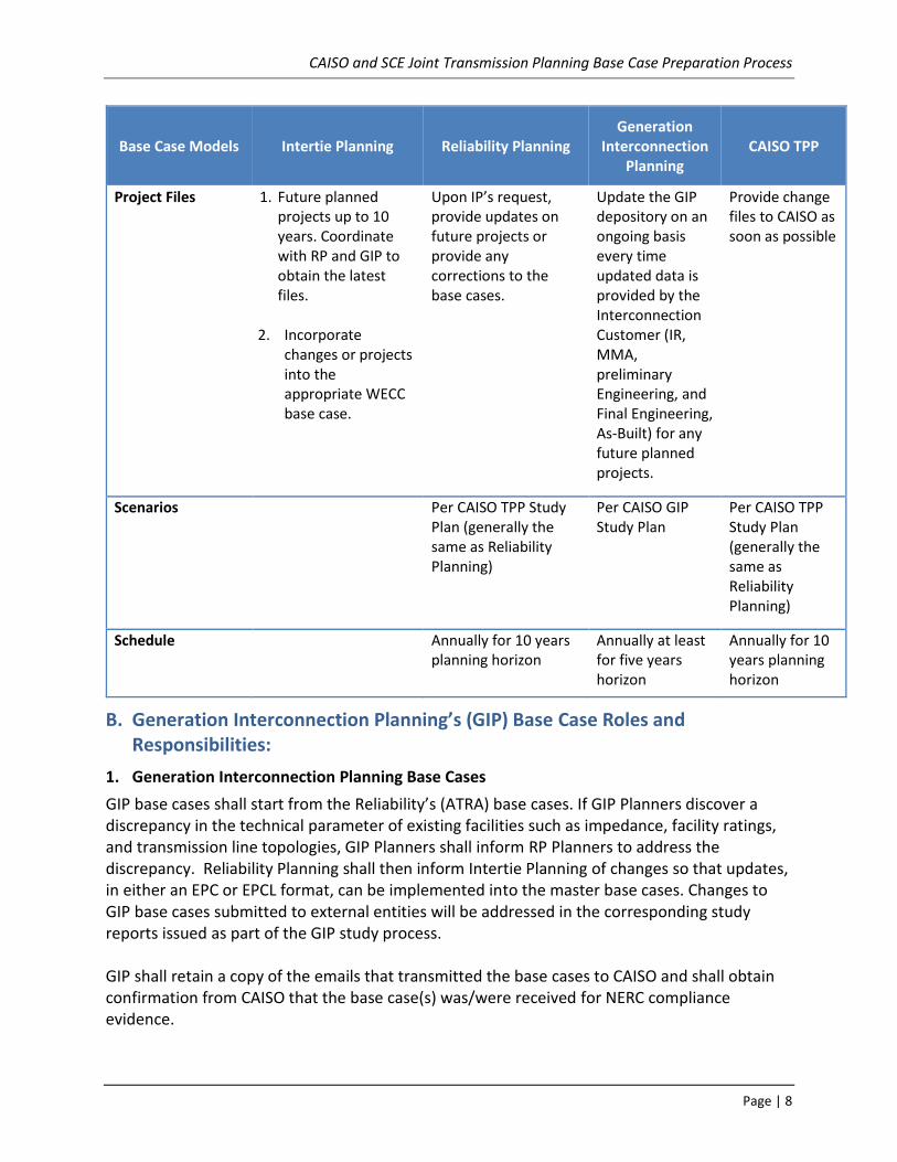
Project Files 1. Future planned projects up to 10 years. Coordinate with RP and GIP to obtain the latest files.
2. Incorporate
changes or projects into the appropriate WECC base case.
Upon IP’s request, provide updates on future projects or provide any corrections to the base cases.
Update the GIP depository on an ongoing basis every time updated data is provided by the Interconnection Customer (IR, MMA, preliminary Engineering, and Final Engineering, As-Built) for any future planned projects.
Provide change files to CAISO as soon as possible
Scenarios Per CAISO TPP Study Plan (generally the same as Reliability Planning)
Per CAISO GIP Study Plan
Per CAISO TPP Study Plan (generally the same as Reliability Planning)
Schedule Annually for 10 years planning horizon
Annually at least for five years horizon
Annually for 10 years planning horizon
B. Generation Interconnection Planning’s (GIP) Base Case Roles and Responsibilities:
1. Generation Interconnection Planning Base Cases
GIP base cases shall start from the Reliability’s (ATRA) base cases. If GIP Planners discover a discrepancy in the technical parameter of existing facilities such as impedance, facility ratings, and transmission line topologies, GIP Planners shall inform RP Planners to address the discrepancy. Reliability Planning shall then inform Intertie Planning of changes so that updates, in either an EPC or EPCL format, can be implemented into the master base cases. Changes to GIP base cases submitted to external entities will be addressed in the corresponding study reports issued as part of the GIP study process. GIP shall retain a copy of the emails that transmitted the base cases to CAISO and shall obtain confirmation from CAISO that the base case(s) was/were received for NERC compliance evidence.
CAISO and SCE Joint Transmission Planning Base Case Preparation Process
Page | 9
GIP base case assumptions for GIP studies are identified in the CAISO GIP study plan. These base cases are modified to include transmission and generation facilities in accordance with the GIP study process and shall only be provided for GIP studies or base cases.
2. New Generation and Interconnection Facilities:
The following provides the roles and responsibilities for Transmission Planning’s Groups to model new or existing generators.
a. GIP will update the progress of queued generation in the Generator Interconnection Planning Project Data Depository and will notify the Preparer and RP of the status of new projects when requested.
For example, generators in-service or under construction will be modeled in the base cases. Also, if generator projects are placed in-service in phases, the Preparer will model the generators with respect to the commercial operation date of each phase.
b. GIP is responsible for reviewing the initial design, final engineering, and As-Built data for the interconnection customer generating facilities, to be provided by the Interconnection Customer in accordance with executed GIAs.
c. The following is required by the WECC Generating Unit Model Validation Policy:
Generator Owner Responsibilities
Generating Facility Data
The Generator Owner shall provide to the Transmission Planner the information for the Generating Facility as specified in the WECC’s Generating Facility Data Requirements document.
The Generator Owner shall review, verify, and update the Generating Facility data no later than 180 days after the new Generating Facility is released for Commercial Operation.
Intertie Planning will assume the responsibility of monitoring the status of the generator’s test data per the WECC Generating Unit Model Validation Policy which is required as stated above 180 days after commercial operation.
3. Network Upgrades or SPS for Interconnecting Generators
a. The status updates of transmission facility upgrades will be maintained by GIP (or project sponsor). The responsible GIP project sponsor shall post the changes on the Generator Interconnection Planning Project Data Depository and will notify the Preparer on a monthly bases of any changes to network upgrades, including upgrades that are placed in service. These upgrades include, if any, but not limited to: impedances, facility ratings, line distances, and locations.
b. Any SPS that are associated with new generation projects and are included in GIAs are the responsibility of GIP. The project sponsor must obtain approval from WECC’s RASRS. Once the approval is granted and the SPS is placed in-service, it will be the responsibility of the Reliability Planning group to continue assessments (excluding any modifications associated with subsequent new generation projects).

CAISO and SCE Joint Transmission Planning Base Case Preparation Process
Page | 10
c. GIP will update and maintain SCD data for new generation projects and associated transmission facilities until such upgrades are placed into service and as-build information is provided. Any future changes to upgrades not driven by generation interconnection requests will be updated and maintained by the appropriate organization where the modification need is identified.
d. In addition to generators that are already in-service, new generators will be modeled in the base cases, on an as needed basis.
C. Reliability Planning’s (RP) Base Case Roles and Responsibilities:
1. Prepare and Update Transmission Planning’s ATRA Base Case
a. On an annual basis, RP shall prepare the ATRA base cases that the Preparer will use to update SCE’s latest WECC Master Base Cases.
b. The RP group will monitor the progress of reliability-driven projects and provide the following to the Preparer: 1) updates or corrections to existing transmission facilities, 2) project files for newly approved transmission and generation facilities. Transmission facilities include: transmission lines, transformers, loads, reactive support devices (e.g. shunt capacitors and reactors, series capacitors, SVCs, SVDs, synchronous condensers, etc), special protection schemes, and other power system devices. Project files shall include simulation models with associated parameters (impedances, ratings, and susceptance), location, distance, and plan of service, and 3) confirmed review comments and change files developed as part of CAISO TPP Planning base case development work. RP will provide these materials to the Preparer.
c. RP shall concurrently notify the Preparer, GIP planners, and CAISO of any data correction changes and subsequently send a change file to make those changes.
2. Reliability Planning’s ATRA Base Cases:
RP will review generator projects from the GIP’s database for status updates and determine which projects shall be included into the ATRA base cases. On an as needed basis, the Preparer will request updates on RP’s project files that will be incorporated into the master base case. Upon receipt of this request, the responsible RP project sponsor shall post the changes in an EPC or EPCL format on the Transmission Planning’s share drive and will notify the Preparer by email of these changes. The status of updates to transmission facilities will be maintained by RP (or project sponsor). Once the network upgrades are placed in service or approved by CAISO, RP or the project sponsor will provide project updates to the Preparer, if any, of the new transmission facilities’ parameters including impedances, facility ratings, line distances, and locations.
For NERC compliance evidence, the planner submitting these base cases to CAISO (via CAISO secure website) shall request a confirmation email from CAISO that they received the base cases.

CAISO and SCE Joint Transmission Planning Base Case Preparation Process
Page | 11
D. Intertie Planning’s (IP) Base Case Roles and Responsibilities:
The Base Case Preparer will be responsible for preparing and submitting WECC base cases to WECC (ERO or its designee). Each WECC base case will be developed from one of SCE’s WECC master base cases. The Preparer will maintain the master base cases and coordinate with the Transmission Planning groups to ensure that the latest modeling data for existing and future facilities are reflected in these master base cases. The Preparer will coordinate with the responsible planners who are providing the models and ensure, that they meet all applicable NERC Reliability Standards and WECC Policies prior to modeling in the master base cases. The Preparer shall also coordinate with CAISO to ensure that the WECC ADS base case meets data requirements.2 The Preparer shall coordinate with the transmission planning groups and perform an annual review of the latest master base cases. This review shall include comparing the latest WECC master base cases with the ATRA base cases. The review shall consist of validating ratings, impedances, topology, and updating dynamic data models. The Responsible Planner will maintain project files with the latest in-service dates and provide them to the Preparer for inclusion into the WECC base cases based on the month and year represented by the case. The Preparer will review generator projects for status updates and determine which projects shall be included in the WECC base cases based on the month and year represented by the case.
E. CAISO’S Roles and Responsibilities
Every year CAISO posts the CAISO Transmission Planning Process Study Plan developed along with the stakeholders. CAISO planners review the study plan with RP and kicks off the Transmission Planning Process. The reliability assessment is performed on the bulk system and the local areas for 10 years planning horizon to ensure that the performance of the system under the CAISO controlled grid will meet or exceeds the applicable reliability standards. TPP base cases shall start from the latest ATRA base cases. The ATRA case shall include up-to-date information of the existing facilities, future generation, and transmission projects for the next 10 year horizon. RP will provide a list of renewable projects that are either under construction or recently went in to service to the CAISO Planners. RP will model and dispatch these renewable projects pursuant to the ISO Study Plan. RP will provide a list of all additional and retirements of generation, transmission, and other projects that will be modeled in the planning cases. CPUC provides the CAISO with the RPS portfolios to be used in the TPP annually. CAISO Planners will compare the RP and CPUC list and identify the additional projects that needs to be modeled to meet the Renewable Portfolio Standard (RPS) requirements. CAISO Planners will provide to RP the list of additional generation that needs to be modeled in the ATRA base case and a list of any new conventional generation resources, as per CAISO study plan, that needs to be modeled. RP will model this additional RPS renewable generation and dispatch these renewable generators pursuant to the ISO Study Plan. CAISO Planners will also communicate this list of
2 Refer to Appendix E for further details on Anchor Data Set development.
CAISO and SCE Joint Transmission Planning Base Case Preparation Process
Page | 12
additional projects that need to be modeled to meet the RPS requirements to the Preparer, to be modeled in the WECC ADS3 base case. CEC will post 1-in-10 demand forecast and provide allocation of Additional Achievable Energy Efficiency (AAEE) to bus-bar locations. RP will updates the seed ATRA base cases according to the Study Plan incorporating topology changes, CEC load forecast, CEC allocation of AAEE, path flows, and CAISO new resources. RP will develop dyd files, p1-p7 contingency files (categorized as much as practicable), A bank load forecast tables, and switch deck files and will provide this information to CAISO. RP will ensure that the provided DYD files with renewables included will have a flat no fault run. CAISO Planners will review the provided information and communicate back any concerns identified in the base case to RP via written comments. SCE will update the current ATRA and SCE WECC Master Base Cases, as needed, to address CAISO’s written comments. Once the outstanding concerns are resolved, if any, CAISO will merge SDGE base case with the SCE base case and will build the full loop base case as specified in the CAISO study plan. CAISO will work with SDGE to obtain their TPP base case to be merged with SCE. RP will provide the bulk system and the local area base cases for the years in the study plan and CAISO Planners will start the TPP study.
F. PTO or non-PTO Roles and Responsibilities
1. Initial Base Case Data Submittal
a. Each PTO or non-PTO in area 24 shall provide their system load forecast to SCE and CAISO on an annual basis by June 1 of each year, or submit their loads for each WECC base case scenario in accordance with the WECC Base Case Compilation Schedule or revised schedule/dates as communicated by WECC.
b. If changes are needed to the base case models, PTOs and non-PTOs shall submit their data to the responsible SCE transmission planner and CAISO in accordance with the WECC Base Case Compilation Schedule or revised schedule/dates as communicated by WECC for the requested WECC base case scenario.
c. Generator Owners within area 24 of the WECC base cases shall submit their data to SCE and CAISO, if applicable for the base case scenarios, if changes are needed to the base case.
d. APS/SRP, SDG&E, CDWR, VEA, IID, WAPA, LADWP, MWD, NVE, and PG&E shall submit the necessary interchange or pump load data in accordance with the WECC’s Annual Study Program Compilation Schedule.
e. SCE will adjust the load forecast to meet the base case scenario request.
3 Refer to Appendix E for further details on Anchor Data Set development.

CAISO and SCE Joint Transmission Planning Base Case Preparation Process
Page | 13
f. All data submittals shall be provided to SCE at [email protected] and CAISO at [email protected].
2. WECC’s Base Cases for Base Case Review
PTO and non-PTOs have the opportunity to provide review comments and the appropriate signoff sheet(s) for each WECC base case review request. SCE will send an email notice to remind PTO and non-PTOs for their comments and appropriate signoff sheet(s) for each WECC base case review request. Theses review comments must be received by SCE prior to the stipulated deadline in-order for them to be incorporated into the base case. There are two options for submitting power flow and dynamic data. These options are consistent with the interconnection-wide process.
Option 1: (Without PSLF)
The power flow data are available in GE PSLF format on the WECC website (www.wecc.biz).
Step 1: On the main page, enter your login information.
Step 2: Click on base cases in the popular searches panel.
Step 3: Select the year of the base case.
Step 4: Click the appropriate base case for review.
Step 5: Click on the base case supplemental.zip file.
Step 6: Click on the appropriate base case SCE.xls excel file.
Step 7: Review the appropriate worksheet for SCE Interchanges, Pumpload, Loads, and/or Generation.
Step 8: Download the signoff sheet(s) in the appropriate base case for review link.
Step 9: Check the appropriate Data Comment on the signoff sheet(s) and send the signoff sheet(s), via email, to CAISO and SCE. If a change is needed, check the appropriate box and send the change in a text format, via email, with the signoff sheet(s).
Option 2: (With PSLF)
Step 7B Follow the above steps and add Step 7b to download the base case and review.
Step 9B If a change is needed other than revising the load or generation dispatch (e.g. line rearrangement or new transmission facilities), provide a change file (epcl or epc format) or the base case to SCE, and a description of the change in text format.
G. Base Case Submittals to WECC
SCE is responsible for submitting WECC base cases and review comments for Area 24 to the Southern California Area Coordinator or, if SCE is the area coordinator, to WECC in accordance with the WECC Base Case Compilation Schedule or revised schedule/dates as communicated by WECC. When an issue of submittal timing warrants extending the deadline, SCE may modify the due dates, not to exceed 15 calendar days, by an agreed upon extension between the

CAISO and SCE Joint Transmission Planning Base Case Preparation Process
Page | 14
Southern California Area Coordinator, WECC, or the CAISO. SCE will provide the initial base cases to CAISO for review and comment. The CAISO will review SCE base case data and provide comments to SCE during the Base Case Review Process4. SCE will provide written response to the CAISO, using the case review sign-off sheet in Appendix D, confirming that the WECC Base Case has been updated to address CAISO’s review comments or provide an explanation for maintaining the current data. SCE will provide base case data or review comments for Area 24 to the Southern California Area Coordinator or, if SCE is the area coordinator, to WECC. If SCE provides the base case data or review comments for Area 24 to the Southern California Area Coordinator, the Southern California Area Coordinator will provide the base case data or Review Comments to WECC. In addition, SCE and CAISO will keep documentation records for a minimal of four years.
4 The ISO, in agreement with SCE, has developed a case review sign-off sheet for providing WECC Base Case Review comments to SCE (Appendix D)
CAISO and SCE Joint Transmission Planning Base Case Preparation Process
Page | 15
The California Independent System Operator (CAISO) & Southern California Edison (SCE) Joint Transmission Planning Base Case Preparation Process (Joint Base Case Process) each entity’s individual and joint responsibilities for implementing Requirement 1 and its sub-requirements of the NERC MOD-032-1 Reliability Standard. These individual and joint responsibilities were determined by the ISO and SCE, and are identified in the Joint Base Case Preparation Process document, which was developed in 2014 and 2015 through conference calls and email exchanging information held between the CAISO and SCE. The Parties signing this procedure document agree that accurately identifies their respective roles and responsibilities for implementing Requirement 1 and its sub-requirements for MOD-032-1.
Original Signed by:
___________________ August 30, 2017______
Robert Sparks Date
California ISO, Manager, Regional Transmission-South, Infrastructure Development
___________________ August 30, 2017______
Ayman Samaan Date
SCE, Engineering Manager, Transmission Intertie Planning
CAISO and SCE Joint Transmission Planning Base Case Preparation Process
Page | 16
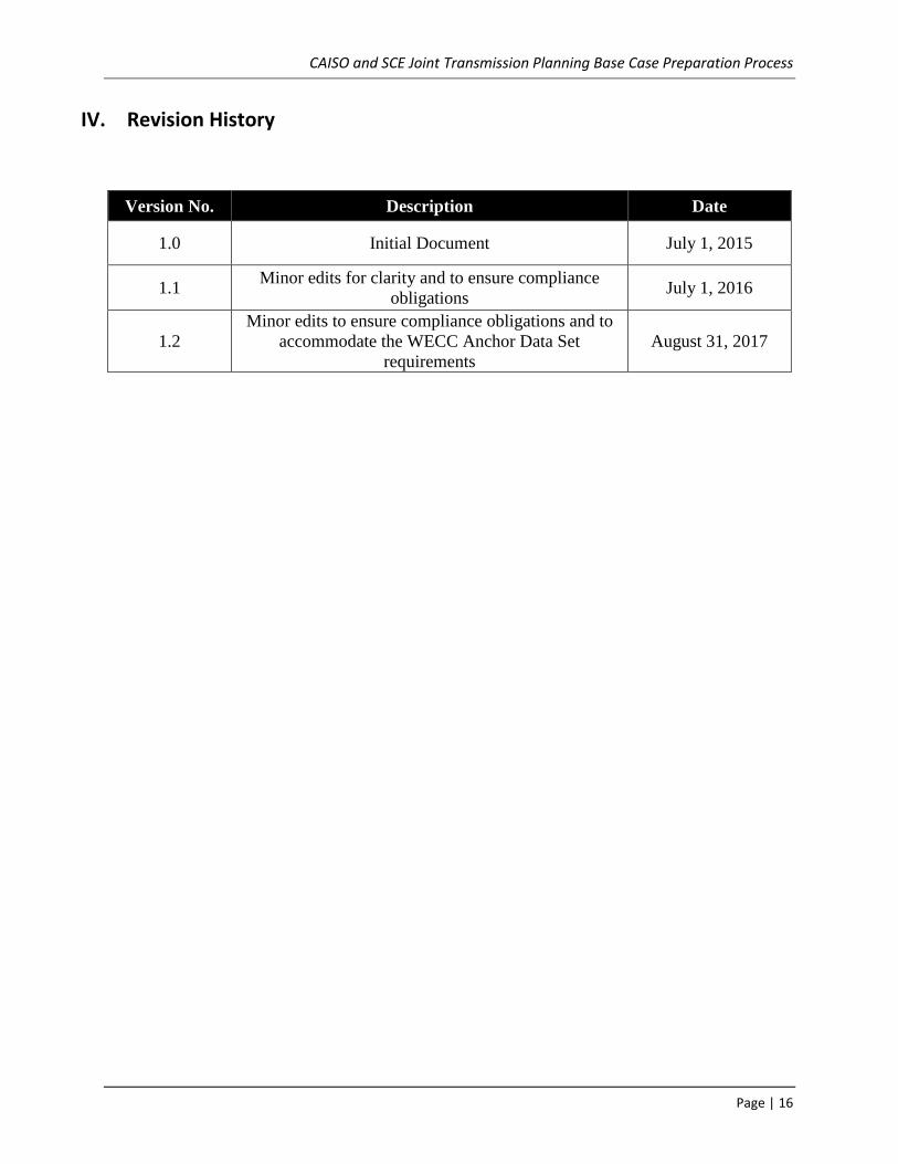
IV. Revision History
Version No. Description Date
1.0 Initial Document July 1, 2015
1.1 Minor edits for clarity and to ensure compliance
obligations July 1, 2016
1.2
Minor edits to ensure compliance obligations and to
accommodate the WECC Anchor Data Set
requirements
August 31, 2017

CAISO and SCE Joint Transmission Planning Base Case Preparation Process
Page | 17
Appendix A
DATA PREPARATION AND DATA VALIDATION
The modeling requirements in Appendix A were extracted from the current WECC DPM. Where there are differences between Appendix A and the latest approved WECC DPM, the latest approved WECC DPM shall be followed with the exception of following
Generating facilities less than 10 MVA may be model explicitly or aggregated.
Aggregated generation capacity that is 20 MVA or larger, and is connected to the WECC transmission system at 60 kV or higher, and is a collector–based generation facility, then steady-state data and dynamics data shall be submitted for the generation facility as a single-unit generator model or multiple-unit generator models. (Wind and solar farms are an example of a collector-based generation facility.)
A. Base Case Preparation
AC and DC Buses
a. Buses usually represent all of the equipment in a substation that is at the same voltage level and is connected together. If desired, multiple bus sections within a substation can be represented by separate buses connected by Connectors or AC Transmission Line models that can be opened or closed as needed. Buses may also represent a node on a transmission line such as a tapping point or change in ownership.
b. Location of the bus will be identified by the combination of Area, Zone, and/or Owner fields. Optionally, the latitude and longitude fields can be submitted using decimal degrees with data entered not to exceed five decimal places.
c. See Appendix A, Table 1: Data Requirements (Buses) for further modeling details.
Generators
a. Modeling of generators shall comply with the following:
i. If the individual generator unit capacity is 10 MVA or larger, and is
connected to the WECC transmission system at 60 kV or higher, then
steady-state data and dynamics data shall be submitted for each
generator.
ii. If the aggregated generator unit capacity is 20 MVA or larger, and is
connected to the WECC transmission system at 60 kV or higher, and is
not a collector–based generation facility, then steady-state data and

CAISO and SCE Joint Transmission Planning Base Case Preparation Process
Page | 18
dynamics data shall be submitted for each generator. (Wind and solar
farms are an example of a collector-based generation facility.)
b. Steady-state and dynamic generator data shall be consistent. c. Synchronous motors 10 MVA and larger shall be modeled as individual machines,
using a generator model with negative Real Power Output and constant Reactive Power (Q) output.
d. Induction motors shall be modeled as a load with the intent of using an induction motor model (MOTORW).
e. Synchronous condensers shall be modeled individually using a generator model. f. Generator step-up transformers shall be modeled explicitly; therefore they shall
not be modeled using the internal generator step-up transformer feature of a generator model. All related parameters shall be set to the default values. See “Data Requirements (Transformers)”.
g. Station service loads (ID = ‘SS’) shall be represented explicitly as separate loads on the generator bus. See “Data Requirements (Loads).”
h. Wind and photovoltaic plants shall be represented through an equivalent generator(s), equivalent low-voltage to intermediate-voltage transformer, equivalent collector system, and substation transformer between the collector system and the transmission bus. See the WECC Wind Power Plant Power Flow Modeling Guide and PV Plant Power Flow Modeling Guide.
i. Large industrial sites may include imbedded generation. Industrial generators 10 MVA and larger shall be represented in power flow instead of netting with the total load. If a generator is connected to the low side of the bulk power delivery transformer, then the transformer must be represented in the power flow, and the generator and load must be connected to the low-voltage side of the transformer.
j. Generator maximum real power Pmax in power flow must be consistent with the turbine capabilities defined in the Master Dynamics File.
k. Generator data shall be extracted from generator test reports or data obtained from generator owners.
l. See Appendix A, Table 2: Data Requirements (Generation) for further modeling details.
Transmission Lines (AC)
a. Series connected reactive devices modeled in AC Transmission Lines shall be explicitly modeled.
b. AC Transmission Line models connecting two areas as defined by WECC shall be maintained in the “Master Tie-Line File.”
c. When breakers are explicitly represented in the model, they should be modeled as Breakers with the Connector Type field set to Breaker (To be implemented in PSLF).

CAISO and SCE Joint Transmission Planning Base Case Preparation Process
Page | 19
d. AC transmission lines modeled with impedance below X = 0.00029 p.u. (the threshold impedance in PSLF) shall not be used to represent a closed loop (ring bus representation).
e. Normal and emergency thermal rating fields for the seasonal scenario described in the base case data request letter shall be populated for all AC Transmission Line models.
f. Line connected transformers shall not be modeled using the internal line connected transformer feature of a transmission line model; all related parameters shall be set to the default values. See “Data Requirements (Transformers).”
g. Data for AC lines will consider the length of the line when calculating line parameters. For example, long lines will be modeled with impedances adjusted to account for the uniform distribution of the series impedance and shunt admittance along the length of the line.
h. Obtain the limiting component or facility ratings of a transmission line from the CAISO Transmission Registry.
i. If available, obtain transmission line impedances from the GCC 525 KV and 230 KV Impedance Diagrams.
j. Appendix A, Table 3: Data Requirements (AC Transmission) for further modeling details.
DC Transmission Lines
a. Include (at a minimum) the following DC Transmission Line (overhead and underground) requirements: line parameters, Normal and Emergency Ratings, control parameters, rectifier data, and inverter data.
b. MW set-point of converter data shall be equal to or less than the DC Transmission Line Rating.
c. Appendix A, Table 4, Data Requirements (DC Transmission) for modeling details.
Transformers
a. Transformers with no Tap Changing Under Load (TCUL) or phase-shifting capability shall have the Tap Control Type field set to ‘1’ and shall not have TCUL or phase-shifting data included in the cases. Conversion from the latest approved version of PSLF to other widely used programs may create model discrepancies with partial TCUL or phase-shifting data.
b. Transformer data may be entered on either the transformer base (transformer winding MVA base and winding voltage base) or the system model base (100 MVA and system nominal voltage base). Impedance values and tap position values shall use a consistent unit base value for a given transformer.
c. Transformer models connecting two Areas, as defined by WECC, shall be represented in the “Master Tie-Line File.”

CAISO and SCE Joint Transmission Planning Base Case Preparation Process
Page | 20
d. Normal and Emergency thermal rating fields corresponding to the seasonal scenario described in the base case data request letter shall be populated for all Transformer models.
e. The Transformer Impedance Correction Table shall be maintained in the “Master Tie-Line File.”
f. Obtain Transformer Thermal Facility Ratings from SCE SOB No. 33. g. See Appendix A, Table 5, Data Requirements (Transformers).
Fixed Shunt Reactive Elements
a. Represent fixed shunt elements that are directly connected to a bus as bus shunts.
b. Represent fixed shunt elements that directly connect to and switch with a transmission line as line shunts.
c. Fixed Line Shunt models connected to an AC Transmission Line model connecting two Areas as defined by WECC shall be represented in the “Master Tie-Line File” as well as in case data.
d. Fixed shunt reactive devices inside wind and solar projects must be modeled explicitly in power flow.
e. See Appendix A, Table 6, Data Requirements (Fixed Shunts)
Controlled Shunt Reactive Devices
a. Controlled shunt reactive devices models should be used to represent the following devices explicitly in power flow:
i. Mechanically switched shunt capacitors and reactors; ii. Static VAR Compensators;
iii. STATCOMs; and/or iv. Thyristor switched shunt capacitors and reactors.
b. Controlled shunt reactive devices inside wind and solar projects must be modeled explicitly in power flow.
c. The number of explicitly modeled shunts on a bus should be minimized to aid solving
d. See Appendix A, Table 7 Data Requirements (Controlled Shunts)
Loads General Requirements
a. Use the CEC Load Forecast and distribute amongst SCE’s A-Banks, reference SCE’s Transmission & Interconnection Planning Load Forecast Methodology
The below diagram demonstrates the load forecast methodology:

CAISO and SCE Joint Transmission Planning Base Case Preparation Process
Page | 21
b. Real and reactive power for each load shall be provided.
c. Motors 10 MVA or larger shall be modeled as machines.
d. Station service at modeled generation facilities with station service load greater than or equal to 1 MW shall be modeled explicitly. Generator station service load models shall have their Load ID set to ‘SS.’
e. A Long ID shall be provided for each load in accordance with the WECC MVWG Load Long ID Instructions (LID Instructions), either within the case data provided, or in a separate spreadsheet file. Data Submitter shall select an appropriate Long ID that correctly represents the Dynamic load characteristics.
f. Industrial loads and embedded generation shall be modeled on the low side of the transformer, as shown in the following figure:
10 MW
115-kV
WRONG! Industrial load is netted
with embedded generation
100 MW
115-kV
WRONG! Industrial load and
embedded generation are
connected to high voltage bus
G 90 MW
100 MW
115-kV
RIGHT! Industrial load and
embedded generation are
connected to low voltage bus
G 90 MW
13.8-kV

CAISO and SCE Joint Transmission Planning Base Case Preparation Process
Page | 22
g. See Appendix A, Table 8, Data Requirements (Loads)
Dynamic Data
Approved dynamic models conform to the WECC Dynamic Modeling Procedure. All dynamic models contained in the MDF shall be those approved by MVWG. If the model you want to use is not on the approved list, you must go through MVWG and follow the WECC Dynamic Modeling Procedure. The following approach to dynamic data shall apply Interconnection-wide: a. Generators and other dynamic devices shall be represented with approved
dynamic data as recommended by the MVWG to represent the designated dynamic equipment modeled in WECC base cases. The approved models can be found within the Approved Dynamic Model Library.
b. Estimated or typical manufacturer’s dynamic data based on facilities of similar design and characteristics may be used to represent planned generators and other dynamic devices if specific design data cannot be obtained. MVWG maintains the Typical Machine Data document. Specific dynamic design data shall be submitted per the WECC Steady-State and Dynamic Data Criterion.
c. All Generator Models Shall include the following, if applicable: 1. Generator Model Types 2. Governor Models 3. Excitation Models 4. PSS Models
The following criteria shall be used to determine when a PSS shall be installed on a synchronous generator, regardless of ownership, that is connected to the transmission system (by generator step-up transformer to 60 kV or higher voltage):
i. A PSS shall be installed on every existing synchronous generator that is larger than 75 MVA and is equipped with a suitable excitation system as defined in the report “Criteria to Determine Excitation System Suitability for PSS”, dated December 1992 (available on WECC Website, www.wecc.biz).
ii. A PSS shall be installed on every existing synchronous generator that is larger than 30 MVA, or is part of a complex that has an aggregate capacity larger than 75 MVA, if the excitation system is updated so that it becomes a suitable excitation system as defined in the report mentioned in 1a above. This section applies to all machines whose excitation system is updated at any time after November 18, 1993.
iii. A PSS shall be installed on every synchronous generator that is larger
than 30 MVA, or is part of a complex that has an aggregate capacity

CAISO and SCE Joint Transmission Planning Base Case Preparation Process
Page | 23
larger than 75 MVA, and is equipped with suitable excitation systems as defined in paragraph 1a, and is commissioned after November 18, 1993.
d. Underfrequency Load Shedding
i. Include under frequency load shedding records for all loads that have under frequency relays on the interconnected system.
ii. Ensure the pickup frequency of each stage is lower than that of the previous stage. UFLS must comply with WECC-coordinated off-nominal requirements as specified in the WECC Off-Nominal Frequency Load Shedding Plan document.
iii. Include pertinent load data in the MDF. All under-frequency load-shedding data in the MDF must match bus, load, and/or branch identifiers in the cases.
iv. Ensure UFLS models provided correspond to UFLS information provided to WECC Under-Frequency Load-Shedding Review Group in accordance with WECC Under-Frequency Load Shedding Criterion.
SCD Data
Short circuit data is necessary to perform a myriad of studies such as breaker duty evaluation and relay coordination. The necessary data includes the zero, positive, and negative sequence data of transmission lines but also includes but not limited to the generator characteristics and transformer winding connections.
1. Positive Sequence 2. Negative Sequence 3. Zero Sequence 4. Mutual Coupling Line Impedance 5. Transformer Winding Connections 6. Auxiliary transformers / equipment connected at the tertiary (i.e.
grounding transformers, series reactors, etc.)
Relays
Include relay models as approved for use by the RDWG per the time line and scope it establishes for primary relays, e.g., overcurrent relays. Data submitters are also strongly encouraged to submit all relevant backup relay modeling data.

CAISO and SCE Joint Transmission Planning Base Case Preparation Process
Page | 24
Data Requirements AC AND DC General requirements:
Table 1: Data Requirements (Buses)
Field Description Requirements
Number Bus number B1. WECC staff shall provide DC Bus numbers.
Name Bus name
Alphanumeric string containing 1 to 12 characters
At least one non-numeric character
B2. Bus names shall be unique within the same Base Voltage class.
Base Voltage
Nominal voltage class of Bus (kV)
Bus Type
AC Bus type {0,1,2,-2}
0 = swing bus (voltage magnitude and phase fixed)
1 = load bus (unconstrained voltage angle and magnitude)
2 = generator bus (voltage control [terminal or remote] within generator limits)
-2 = generator bus with unlimited reactive power limits
Other bus types may be used to indicate OFF status.
Bus type -4 and smaller is the accepted convention for deleted buses.
DC Bus type {1,2}
1 = for a rectifier
2 = for an inverter
DC System Number
DC system number (not required for AC Bus)
B3. WECC staff shall assign a DC system number for each DC system prior to model submission.
CAISO and SCE Joint Transmission Planning Base Case Preparation Process
Page | 25
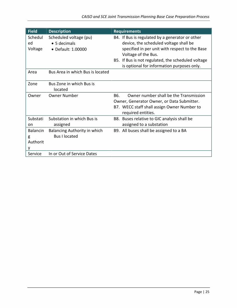
Field Description Requirements
Scheduled Voltage
Scheduled voltage (pu)
5 decimals
Default: 1.00000
B4. If Bus is regulated by a generator or other device, the scheduled voltage shall be specified in per unit with respect to the Base Voltage of the Bus.
B5. If Bus is not regulated, the scheduled voltage is optional for information purposes only.
Area Bus Area in which Bus is located
Zone Bus Zone in which Bus is located
Owner Owner Number
B6. Owner number shall be the Transmission Owner, Generator Owner, or Data Submitter. B7. WECC staff shall assign Owner Number to
required entities.
Substation
Substation in which Bus is assigned
B8. Buses relative to GIC analysis shall be assigned to a substation
Balancing Authority
Balancing Authority in which Bus I located
B9. All buses shall be assigned to a BA
Service In or Out of Service Dates
CAISO and SCE Joint Transmission Planning Base Case Preparation Process
Page | 26
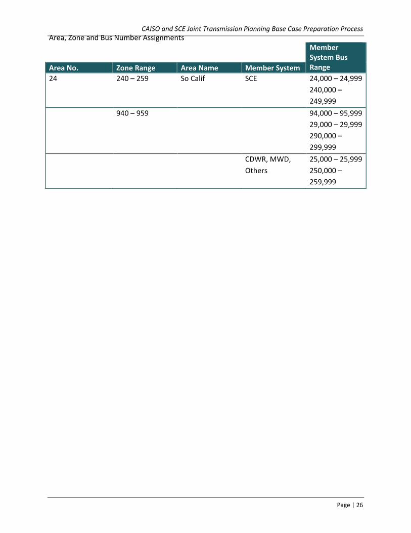
Area, Zone and Bus Number Assignments
Member
System Bus Range Area No. Zone Range Area Name Member System
24 240 – 259 So Calif SCE 24,000 – 24,999
240,000 –
249,999
940 – 959 94,000 – 95,999
29,000 – 29,999
290,000 –
299,999
CDWR, MWD,
Others
25,000 – 25,999
250,000 –
259,999

CAISO and SCE Joint Transmission Planning Base Case Preparation Process
Page | 27
Data Requirements (Generation) General requirements: Table 2: Data Requirements (Generation)
Field Description Requirements Measure
Bus Numbers
Number of the Bus to which the generator is attached.
See “Data Requirements (Buses)”
Unit ID Two -character Generator identifier
Status Generator status
1 = in-service
0 = out-of-service
G1. Out-of-service units shall have status set to zero.
G2. Retired units shall be deleted rather than having status set to zero.
Pgen Real power output (gross MW)
G3. Pgen shall be at or within the unit Pmax and Pmin parameters for units that are in-service.
If Status = 1: Pmin ≤ Pgen ≤ Pmax
Qgen Reactive power output (MVAr)
Pmax Maximum real power output (MW)
G4. Pmax shall reflect the maximum real power output of the unit, also known as ‘gross’ capability.
G5. Pmax shall not be greater than the maximum capability of the unit represented by the governor model.
Pmax ≤ Governor Max
Pmin Minimum real power output (MW)
G6. Pmin shall reflect the minimum real power output of the unit.
G7. Pmin shall be less than or equal to Pmax
Pmin ≤ Pmax
Qmax Maximum reactive power output (MVAr)
G8. Qmax shall reflect the appropriate maximum reactive power output of the unit.

CAISO and SCE Joint Transmission Planning Base Case Preparation Process
Page | 28
Field Description Requirements Measure
Qmin Minimum reactive power output (MVAr)
G9. Qmin shall reflect the appropriate minimum reactive power output of the unit.
G10. Qmin shall be less than or equal to Qmax
Qmin ≤ Qmax
Q Alloc Factor
Reactive power regulating assignment factor
0.0 – 1.0
> 0.0 for AVR control
0.0 for constant PF control or gen Status=0
Q Table Flag
Reactive capability curve flag
0 = do not use capability curve
1 = use capability curve if it exists
G11. Q-Table data used for internal studies shall be included in WECC base case submittals.
G12. PMax value shall exist on the Q Table if used.
Base load Flag
Base load flag
0 = non-base load unit (responds to low frequency with additional mechanical power)
1 = base load unit (cannot respond to low frequency with additional mechanical power)
2 = base load unit (cannot respond to low and high frequency with mechanical power)
CAISO and SCE Joint Transmission Planning Base Case Preparation Process
Page | 29
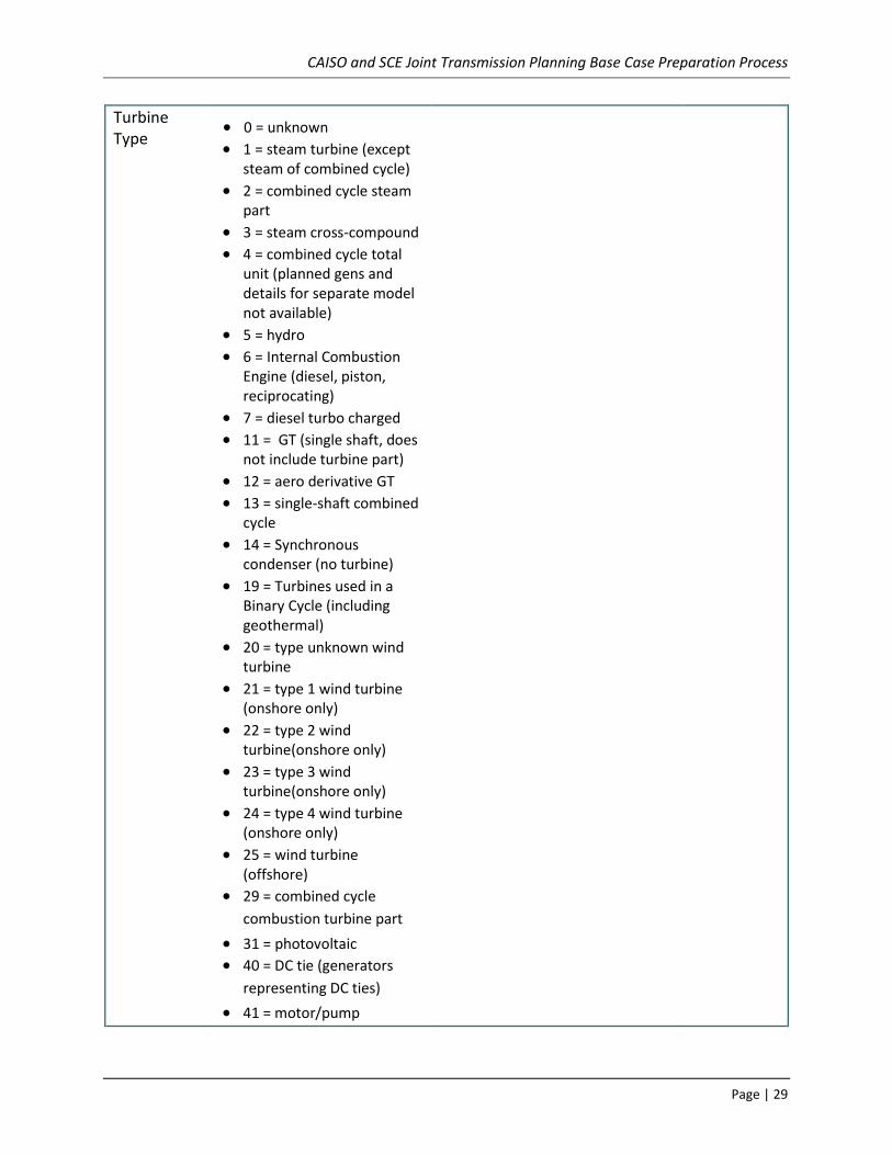
Turbine Type
0 = unknown 1 = steam turbine (except
steam of combined cycle)
2 = combined cycle steam part
3 = steam cross-compound 4 = combined cycle total
unit (planned gens and details for separate model not available)
5 = hydro 6 = Internal Combustion
Engine (diesel, piston, reciprocating)
7 = diesel turbo charged 11 = GT (single shaft, does
not include turbine part)
12 = aero derivative GT 13 = single-shaft combined
cycle
14 = Synchronous condenser (no turbine)
19 = Turbines used in a Binary Cycle (including geothermal)
20 = type unknown wind turbine
21 = type 1 wind turbine (onshore only)
22 = type 2 wind turbine(onshore only)
23 = type 3 wind turbine(onshore only)
24 = type 4 wind turbine (onshore only)
25 = wind turbine (offshore)
29 = combined cycle
combustion turbine part
31 = photovoltaic 40 = DC tie (generators
representing DC ties)
41 = motor/pump

CAISO and SCE Joint Transmission Planning Base Case Preparation Process
Page | 30
Field Description Requirements Measure
42 = energy storage -
battery
43 = energy storage -
flywheel
44 = energy storage –
other
46 = energy storage –
compressed air
47 = energy storage –
concentrated solar power
51 = hydrokinetic, axial
flow turbine
52 = hydrokinetic – wave
buoy
53 = hydrokinetic - other
54 = energy storage –
reversible hydraulic
turbine
99 = other
Reg Bus Bus whose voltage is controlled by this Generator
G13. Regulation of a remote Bus that does not represent actual system operation shall be avoided.
Vsched Generator scheduled voltage (pu)
Area Generator Area in which located
Zone Generator Zone in which located
Base MVA Generator base (MVA) G14. Unit Base MVA shall be equal to the MVA Base parameter of the unit’s Dynamic machine model.
Base MVA = Machine Base
Owner Owner Number
Up to 8 owners allowed
G15. Owner Number shall be the Generator Owner.
G16. WECC staff shall assign Owner Number to required entities.
G tap Tap ratio of generator step up transformer
G17. G tap shall be set to 1. G tap = 1

CAISO and SCE Joint Transmission Planning Base Case Preparation Process
Page | 31
Field Description Requirements Measure
R TR Resistance of generator step up transformer
G18. R TR shall be set to 0. R TR = 0
XTR Reactance of generator step up transformer
G19. X TR shall be set to 0. X TR = 0
R Sub transient
Sub transient resistance of generator
X Sub transient
Sub transient reactance of generator
G20. X Sub transient shall be equal to the sub transient reactance represented in the unit Dynamic machine model.
X Sub transient = Xdpp (or Ldpp)
Balancing Authority
Balancing Authority Area in which Generator is located
Service In Service or Out of Service Dates
Additional data for short circuit duty
Field Description Requirements Measure
R0 Zero Sequence Resistance of generator
X0 Zero Sequence Reactance of generator
R- Negative Sequence Resistance of generator
X- Negative Sequence Reactance of generator
GND Ground Connection
Solidly Grounded
Through Impedance
R Resistance of Grounding Circuit
X Reactance of Grounding Circuit
CAISO and SCE Joint Transmission Planning Base Case Preparation Process
Page | 32
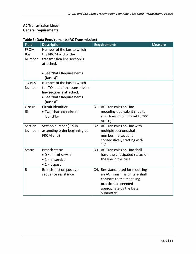
AC Transmission Lines General requirements: Table 3: Data Requirements (AC Transmission)
Field Description Requirements Measure
FROM Bus Number
Number of the bus to which the FROM end of the transmission line section is attached.
See “Data Requirements (Buses)”
TO Bus Number
Number of the bus to which the TO end of the transmission line section is attached.
See “Data Requirements (Buses)”
Circuit ID
Circuit identifier
Two-character circuit identifier
X1. AC Transmission Line modeling equivalent circuits shall have Circuit ID set to ‘99’ or ‘EQ.’
Section Number
Section number (1-9 in ascending order beginning at FROM end)
X2. AC Transmission Line with multiple sections shall number the sections consecutively starting with ‘1.’
Status Branch status
0 = out-of-service
1 = in-service
2 = bypass
X3. AC Transmission Line shall have the anticipated status of the line in the case.
R Branch section positive sequence resistance
X4. Resistance used for modeling an AC Transmission Line shall conform to the modeling practices as deemed appropriate by the Data Submitter.
CAISO and SCE Joint Transmission Planning Base Case Preparation Process
Page | 33
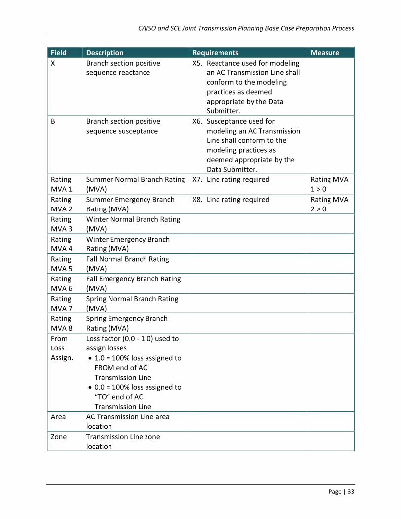
Field Description Requirements Measure
X Branch section positive sequence reactance
X5. Reactance used for modeling an AC Transmission Line shall conform to the modeling practices as deemed appropriate by the Data Submitter.
B Branch section positive sequence susceptance
X6. Susceptance used for modeling an AC Transmission Line shall conform to the modeling practices as deemed appropriate by the Data Submitter.
Rating MVA 1
Summer Normal Branch Rating (MVA)
X7. Line rating required Rating MVA 1 > 0
Rating MVA 2
Summer Emergency Branch Rating (MVA)
X8. Line rating required Rating MVA 2 > 0
Rating MVA 3
Winter Normal Branch Rating (MVA)
Rating MVA 4
Winter Emergency Branch Rating (MVA)
Rating MVA 5
Fall Normal Branch Rating (MVA)
Rating MVA 6
Fall Emergency Branch Rating (MVA)
Rating MVA 7
Spring Normal Branch Rating (MVA)
Rating MVA 8
Spring Emergency Branch Rating (MVA)
From Loss Assign.
Loss factor (0.0 - 1.0) used to assign losses
1.0 = 100% loss assigned to FROM end of AC Transmission Line
0.0 = 100% loss assigned to “TO” end of AC Transmission Line
Area AC Transmission Line area location
Zone Transmission Line zone location

CAISO and SCE Joint Transmission Planning Base Case Preparation Process
Page | 34
Field Description Requirements Measure
Ohms Ohmic data flag
0 = impedances in pu
1 = impedances in ohms
Owner Owner Number (1 through 8) X9. Owner number shall be the Transmission Owner of transmission facility and Generator Owner for lines within generation facility.
X10. WECC staff shall assign Owner Number to required entities.
Service In Service or Out of Service Dates
Additional data for short circuit duty
Field Description Requirements Measure
R- Branch section negative sequence resistance
Usually the same as positive sequence
R0 Branch section zero sequence resistance
X- Branch section negative sequence reactance
Usually the same as positive sequence
X0 Branch section zero sequence reactance
B- Branch section negative sequence susceptance
Usually the same as positive sequence
B0 Branch section zero sequence susceptance
FROM Bus (1)
Number of the bus to which the FROM end of the transmission line section is attached which has mutual coupling with this line

CAISO and SCE Joint Transmission Planning Base Case Preparation Process
Page | 35
Field Description Requirements Measure
TO Bus (1)
Number of the bus to which the TO end of the transmission line section is attached which has mutual coupling with this line
Circuit ID (1)
Circuit identifier that has mutual coupling with this line
Two-character circuit identifier
M(1) Zero Mutual Impedance between this line and (1) line
FROM Bus (2-8)
Repeat for all other lines that have mutual coupling with this line
FROM Bus (2-8)
Repeat for all other lines that have mutual coupling with this line
Circuit ID (2-8)
Repeat for all other lines that have mutual coupling with this line
M(2-8) Repeat for all other lines that have mutual coupling with this line

CAISO and SCE Joint Transmission Planning Base Case Preparation Process
Page | 36
DC Transmission Lines General requirements: Table 4: Data Requirements (DC Transmission)
Field Description Requirement Measure
ifrom DC ‘FROM’ bus number
ito DC ‘TO’ bus number
ck[2] DC line identifier
projid Project Identifier
st DC line status
dcsys DC system number
area Area number
zone Zone number
r DC line resistance ohms
l DC line inductance henries
c DC line capacitance microfarad
rate[8] DC current ratings amps
aloss DC line loss assignment factor per unit
nown[8] Owner number
Balancing Authority
Balancing Authority Area in which DC bus & converter are located
Service In Service or Out of Service Dates

CAISO and SCE Joint Transmission Planning Base Case Preparation Process
Page | 37
Transformers General Requirements Table 5: Data Requirements (Transformers)
Field Description Requirements Measure
FROM Bus Number
Number of the bus to which the FROM end of the transformer is attached.
See “Data Requirements (Buses)”
TO Bus Number
Number of the bus to which the “TO” end of the transformer is attached.
See “Data Requirements (Buses)”
Circuit ID Circuit identifier
Two-character circuit identifier
T1. Transformer modeling equivalent circuits shall have Circuit ID set to ‘99’ or ‘EQ.’
Status Transformer Status
0 = out-of-service
1 = in-service
2 = secondary open
3 = tertiary open
4 = primary open
T2. Transformers shall have the anticipated status of the transformer in the case.
Tap Control Type
Transformer type code
1 or 11 = Fixed
2 or 12 = TCUL
-2 or -12 TCUL Disabled
4 or 14 = Phase-Shifting
-4 or -14 = Phase Shifting Disabled
T3. TCUL Disabled and Phase Shifting Disabled should be used to represent a temporary physical changed in transformer control or to address potential modeling issues
Regulated Bus Number
Number of Bus whose voltage is regulated or “TO” bus number for phase-regulated transformer
T4. Regulation of a remote bus that does not represent actual system operation shall be avoided.
Impedance Table Number
Impedance correction table number
Tert Bus Number
Tertiary winding Bus number
See “Data Requirements (Buses)”
CAISO and SCE Joint Transmission Planning Base Case Preparation Process
Page | 38
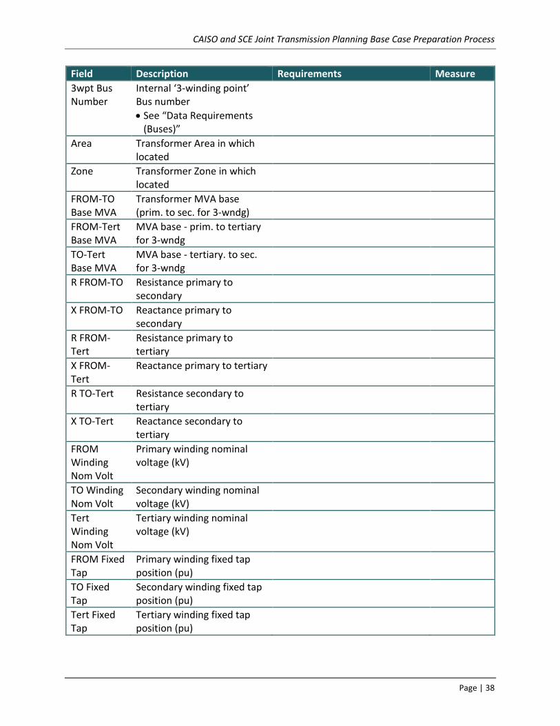
Field Description Requirements Measure
3wpt Bus Number
Internal ‘3-winding point’ Bus number
See “Data Requirements (Buses)”
Area Transformer Area in which located
Zone Transformer Zone in which located
FROM-TO Base MVA
Transformer MVA base (prim. to sec. for 3-wndg)
FROM-Tert Base MVA
MVA base - prim. to tertiary for 3-wndg
TO-Tert Base MVA
MVA base - tertiary. to sec. for 3-wndg
R FROM-TO Resistance primary to secondary
X FROM-TO Reactance primary to secondary
R FROM-Tert
Resistance primary to tertiary
X FROM-Tert
Reactance primary to tertiary
R TO-Tert Resistance secondary to tertiary
X TO-Tert Reactance secondary to tertiary
FROM Winding Nom Volt
Primary winding nominal voltage (kV)
TO Winding Nom Volt
Secondary winding nominal voltage (kV)
Tert Winding Nom Volt
Tertiary winding nominal voltage (kV)
FROM Fixed Tap
Primary winding fixed tap position (pu)
TO Fixed Tap
Secondary winding fixed tap position (pu)
Tert Fixed Tap
Tertiary winding fixed tap position (pu)

CAISO and SCE Joint Transmission Planning Base Case Preparation Process
Page | 39
Field Description Requirements Measure
Variable V Tap or Variable Angle
TCUL tap position (primary winding) or phase angle position
T5. Variable V Tap or Variable Angle shall be at or within Max VAr Tap and Min VAr Tap for Transformers that are in-service.
Min VAr Tap ≤ V Tap ≤ Max VAr Tap
Step Size TCUL (pu) or phase-shift (angle in deg) step
T6. Step Size shall reflect the capability of the transformer.
FROM Angle
Primary winding phase angle (deg)
TO Angle Secondary winding phase angle (deg)
Tertiary Angle
Tertiary winding phase angle (deg)
G-Core Loss Magnetizing conductance (pu)
B Magnetizing
Magnetizing susceptance (pu)
Rating 1 Summer Normal Branch Rating (MVA) (primary winding for 3-winding xfmr)
T7. Transformer rating required Rating MVA 1 > 0
Rating 2 Summer Emergency Branch Rating (MVA) (primary winding for 3-winding xfmr)
T8. Transformer rating required Rating MVA 2 > 0
Rating 3 Winter Normal Branch Rating (MVA) (primary winding for 3-winding xfmr)
Rating 4 Winter Emergency Branch Rating (MVA) (primary winding for 3-winding xfmr)
Rating 5 Fall Normal Branch Rating (MVA) (primary winding for 3-winding xfmr)
Rating 6 Fall Emergency Branch Rating (MVA) (primary winding for 3-winding xfmr)
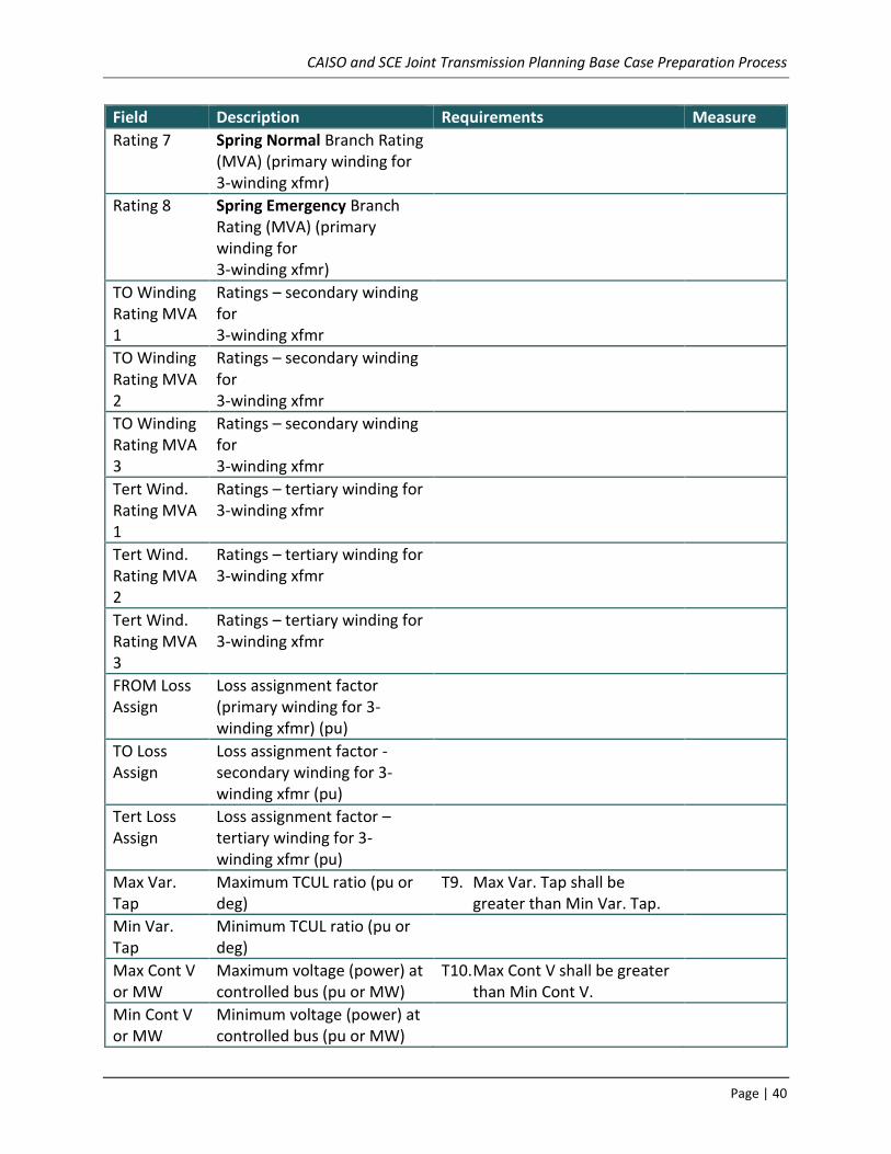
CAISO and SCE Joint Transmission Planning Base Case Preparation Process
Page | 40
Field Description Requirements Measure
Rating 7 Spring Normal Branch Rating (MVA) (primary winding for 3-winding xfmr)
Rating 8 Spring Emergency Branch Rating (MVA) (primary winding for 3-winding xfmr)
TO Winding Rating MVA 1
Ratings – secondary winding for 3-winding xfmr
TO Winding Rating MVA 2
Ratings – secondary winding for 3-winding xfmr
TO Winding Rating MVA 3
Ratings – secondary winding for 3-winding xfmr
Tert Wind. Rating MVA 1
Ratings – tertiary winding for 3-winding xfmr
Tert Wind. Rating MVA 2
Ratings – tertiary winding for 3-winding xfmr
Tert Wind. Rating MVA 3
Ratings – tertiary winding for 3-winding xfmr
FROM Loss Assign
Loss assignment factor (primary winding for 3-winding xfmr) (pu)
TO Loss Assign
Loss assignment factor - secondary winding for 3-winding xfmr (pu)
Tert Loss Assign
Loss assignment factor – tertiary winding for 3-winding xfmr (pu)
Max Var. Tap
Maximum TCUL ratio (pu or deg)
T9. Max Var. Tap shall be greater than Min Var. Tap.
Min Var. Tap
Minimum TCUL ratio (pu or deg)
Max Cont V or MW
Maximum voltage (power) at controlled bus (pu or MW)
T10. Max Cont V shall be greater than Min Cont V.
Min Cont V or MW
Minimum voltage (power) at controlled bus (pu or MW)

CAISO and SCE Joint Transmission Planning Base Case Preparation Process
Page | 41
Field Description Requirements Measure
Ohms Ohmic data flag
0 = impedances in pu
1 = impedances in ohms
Owner Owner Number (1 through 8) T11. Owner number shall be the Transmission Owner for transmission facility and Generator Owner for generator facility.
T12. WECC staff shall assign Owner Number to required entities.
Service In Service or Out of Service Dates
T13.
Additional data for short circuit duty
Field Description Requirements Measure
R0 FROM-TO
Zero Sequence Resistance primary to secondary
X0 FROM-TO
Zero Sequence Reactance primary to secondary
R0 FROM-Tert
Zero Sequence Resistance primary to tertiary
X0 FROM-Tert
Zero Sequence Reactance primary to tertiary
R0 TO-Tert Zero Sequence Resistance secondary to tertiary
X0 TO-Tert Zero Sequence Reactance secondary to tertiary
FROM Bus Connection
Connection can be the following:
Wye
Wye:Auto
Delta:Open
Delta:Close
Delta tested as Wye
Zig-Zag

CAISO and SCE Joint Transmission Planning Base Case Preparation Process
Page | 42
Field Description Requirements Measure
TO Bus Connection
Connection can be the following:
Wye
Wye:Auto
Delta:Open
Delta:Close
Delta tested as Wye
Zig-Zag
TERT Bus Connection
Connection can be the following:
Wye
Wye:Auto
Delta:Open
Delta:Close
Delta tested as Wye
Zig-Zag

CAISO and SCE Joint Transmission Planning Base Case Preparation Process
Page | 43
Fixed Shunt Reactive Elements General Requirements Table 6: Data Requirements (Fixed Shunts)
Field Description Requirement
FROM Bus Number
Number of the Bus to which the FROM end of the transmission line on which the shunt is connected for line shunts or number of the Bus at which shunt is connected for bus shunts.
See “Data Requirements (Buses)”
TO Bus Number
Number of the Bus to which the TO end of the transmission line on which the shunt is connected for line shunts or 0 for bus shunts.
See “Data Requirements (Buses)”
Shunt ID Shunt identifier
Two-character shunt identifier
F1. Line shunt connected to the FROM end of the transmission line shall have Shunt ID starting with ‘F.’
F2. Line shunt connected to the TO end of the transmission line shall have Shunt ID starting with ‘T.’
Circuit ID AC Transmission Line circuit identifier for line shunts or blank for bus shunts
Two-character circuit identifier
Section Number
Number of AC Transmission Line section to which shunt is connected if line shunt or ‘0’ if bus shunt
Shunt Status Shunt status
0 = out-of-service
1 = in-service
F3. Fixed shunts shall have the anticipated status of the shunt in the case
Area Fixed Shunt Area in which located
Zone Fixed Shunt Zone in which located
G Actual shunt conductance (pu)
B Actual shunt susceptance (pu)
Owner Owner Number (1 – 4) F4. Owner number shall be the Transmission Owner or Generator Owner.
F5. WECC staff shall assign Owner Number to required entities.

CAISO and SCE Joint Transmission Planning Base Case Preparation Process
Page | 44
Field Description Requirement
Service In Service or Out of Service Dates

CAISO and SCE Joint Transmission Planning Base Case Preparation Process
Page | 45
Controlled Shunt Reactive Devices General Requirements Table 7: Data Requirements (Controlled Shunts)
Field Description Requirement
Bus Number Number of Bus at which device is connected
See “Data Requirements (Buses)”
SVD ID SVD identifier
Two-character identifier
SVD Status SVD status
0 = out-of-service
1 = in-service
S1. Controlled shunts shall have the anticipated status of the shunt in the case.
SVD Control Type
Device type
0 = Fixed
1 = Discrete
2 = Continuous
3 = All or Nothing
4 = Discrete control using Voltage Dead Band
5=WECC SVC
6=WECC STATCOM
7=WECC TSC/TSR
Regulated Bus Number of Bus regulated by this shunt
See “Data Requirements (Buses)”
S2. Regulation of a remote Bus that does not represent actual system operation shall be avoided.
Area Controlled Shunt Area in which located
Zone Controlled Shunt Zone in which located
G Actual Actual shunt conductance (pu)
B Actual Actual shunt susceptance (pu)
B Min Minimum susceptance of continuous element (pu)
B Max Maximum susceptance of continuous element (pu)

CAISO and SCE Joint Transmission Planning Base Case Preparation Process
Page | 46
Field Description Requirement
Voltage Dead Band
Voltage control bandwidth divided by two (pu) (types 3 & 4)
S3. Voltage Dead Band shall prevent regulated voltage from exceeding the Voltage Dead Band with a single Controlled Shunt step.
S4. The minimum dead band shall be 0.02
B Step Susceptance of each switched element in nth stage (pu) (types 1-4, 7)
S5. Step size shall reflect the capability of the controlled shunt
No. of Steps Number of equal admittance steps in nth switched stage (types 1-4, 7)
S6. Number of steps shall reflect the capability of the controlled shunt
B Min Minimum total susceptance for device (pu)
B Max Maximum total susceptance for device (pu) Maximum current for type 6 (pu)
XC Compensating (slope) reactance (pu) (types 5, 6, 7)
B Min SH Minimum B for switching shunts (pu) (types 5, 6, 7)
B Max SH Maximum B for switching shunts (pu) (types 5, 6, 7)
STSB Slow reset control on/off status (pu) (types 5, 6, 7)
B Min SB Minimum B for slow reset (pu) (pu) (types 5, 7)
B Max SB Maximum B for slow reset (pu) (pu) (types 5, 7)
VRFMIN Minimum Voltage reference for slow reset (pu) (types 5, 6, 7) Minimum Voltage reference for types 3 &4 if Voltage Dead Band <= 0
VRFMAX Maximum Voltage reference for slow reset (pu) (types 5, 6, 7) Maximum Voltage reference for types 3 &4 if Voltage Dead Band <= 0
dVdB System dV/dB for slow reset (pu) (types 5, 6, 7)
Ni Number of steps in shunt
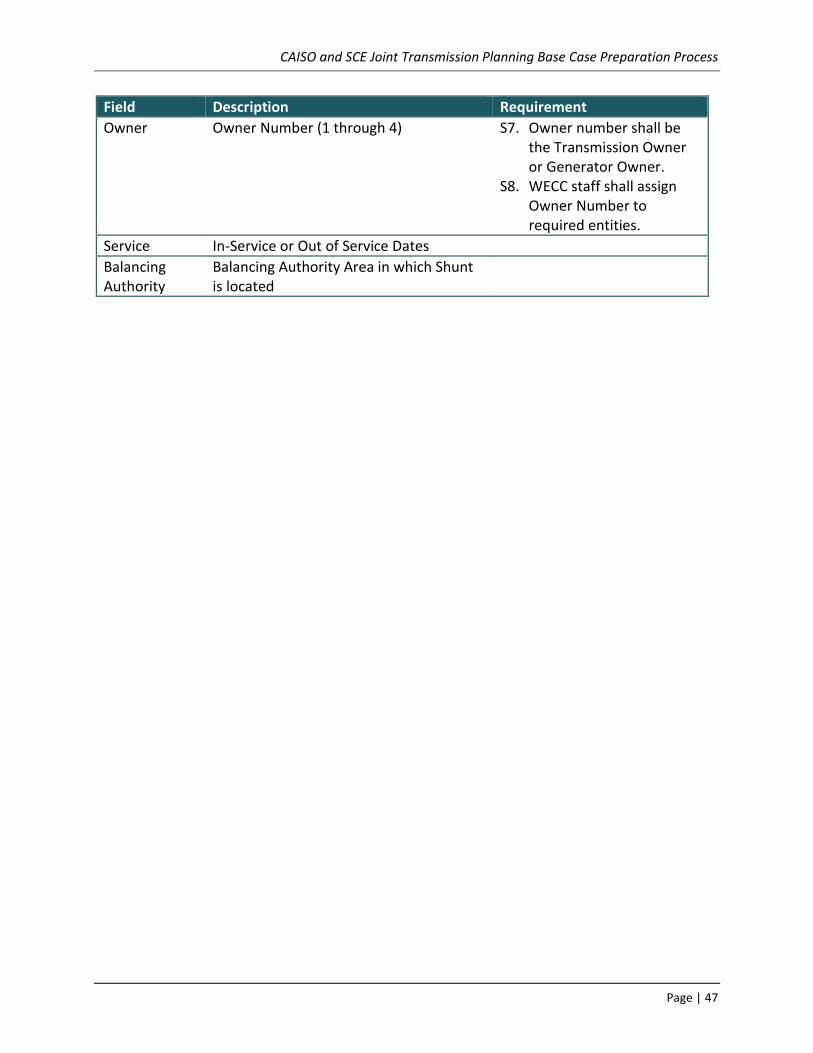
CAISO and SCE Joint Transmission Planning Base Case Preparation Process
Page | 47
Field Description Requirement
Owner Owner Number (1 through 4) S7. Owner number shall be the Transmission Owner or Generator Owner.
S8. WECC staff shall assign Owner Number to required entities.
Service In-Service or Out of Service Dates
Balancing Authority
Balancing Authority Area in which Shunt is located

CAISO and SCE Joint Transmission Planning Base Case Preparation Process
Page | 48
LOADS General requirements: Table 8: Data Requirements (Loads)
Field Description Requirement
Bus Number
Number of Bus at which load is connected
See “Data Requirements (Buses)”
Load ID Two-character identifier L1. Load modeling generator station service shall have Load ID set to ‘SS.’
L2. Loads at the same Bus shall have unique Load ID.
Load Status 0 = load out-of-service
1 = load in-service
L3. Load shall have the anticipated status of the load in the case.
Non-Conforming Flag
0 = load will change with scaling
1 = load does not change with scaling
L4. Non-conforming Flag shall be set to ‘1’ for loads which shall not be changed in load scaling operations of power flow software.
Area Load Area in which located
Zone Load Zone in which located
Const MVA P Constant MVA real power load
Const MVA Q Constant MVA reactive power load
Const CUR P Constant current real power load L5. Const CUR P shall not be used.
Const CUR Q Constant current reactive power load L6. Const CUR Q shall not be used.
Const Y P Constant admittance real power load L7. Const Y P shall not be used.
Const Y Q Constant admittance reactive power load L8. Const Y Q shall not be used.

CAISO and SCE Joint Transmission Planning Base Case Preparation Process
Page | 49
Field Description Requirement
Owner Owner Number L9. Owner number shall be the Transmission Owner for transmission loads, Generator Owner for station service, Distribution Service Provider for distribution loads.
L10. WECC staff shall assign Owner Number to required entities.
Long ID Climate zone and substation type identification
L11. Seven-character identifiers of the climate zone and load type – the first three characters represent the climate zone, followed by underscore, and three characters representing the substation/feeder load mix type. Details are included in the LID_Instructions and Composite Load Model Implementation documents.
Balancing Authority
Balancing Authority Area in which Load is located
Service In-Service or Out of Service Dates

CAISO and SCE Joint Transmission Planning Base Case Preparation Process
Page | 50
Area Interchange Schedules General Requirements
1. Area Interchange schedules shall be coordinated between Areas to meet the objectives of the data request letter.
Master Tie-Line File
The Master Tie-Line File (MTLF) contains:
Master lists of owners and zones;
Path definitions and ratings for paths in the WECC Path Rating Catalog;
Lists of lines and transformers which interconnect areas; and
A placeholder for area-to-area transactions for the existing system.
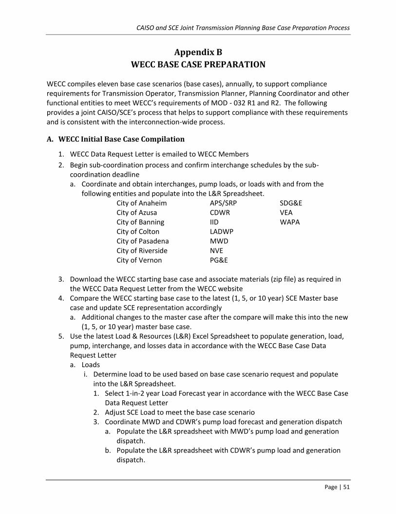
CAISO and SCE Joint Transmission Planning Base Case Preparation Process
Page | 51
Appendix B
WECC BASE CASE PREPARATION
WECC compiles eleven base case scenarios (base cases), annually, to support compliance requirements for Transmission Operator, Transmission Planner, Planning Coordinator and other functional entities to meet WECC’s requirements of MOD - 032 R1 and R2. The following provides a joint CAISO/SCE’s process that helps to support compliance with these requirements and is consistent with the interconnection-wide process.
A. WECC Initial Base Case Compilation
1. WECC Data Request Letter is emailed to WECC Members
2. Begin sub-coordination process and confirm interchange schedules by the sub-coordination deadline a. Coordinate and obtain interchanges, pump loads, or loads with and from the
following entities and populate into the L&R Spreadsheet. City of Anaheim APS/SRP SDG&E City of Azusa CDWR VEA City of Banning IID WAPA City of Colton LADWP City of Pasadena MWD City of Riverside NVE City of Vernon PG&E
3. Download the WECC starting base case and associate materials (zip file) as required in the WECC Data Request Letter from the WECC website
4. Compare the WECC starting base case to the latest (1, 5, or 10 year) SCE Master base case and update SCE representation accordingly a. Additional changes to the master case after the compare will make this into the new
(1, 5, or 10 year) master base case. 5. Use the latest Load & Resources (L&R) Excel Spreadsheet to populate generation, load,
pump, interchange, and losses data in accordance with the WECC Base Case Data Request Letter a. Loads
i. Determine load to be used based on base case scenario request and populate into the L&R Spreadsheet. 1. Select 1-in-2 year Load Forecast year in accordance with the WECC Base Case
Data Request Letter 2. Adjust SCE Load to meet the base case scenario 3. Coordinate MWD and CDWR’s pump load forecast and generation dispatch
a. Populate the L&R spreadsheet with MWD’s pump load and generation dispatch.
b. Populate the L&R spreadsheet with CDWR’s pump load and generation dispatch.

CAISO and SCE Joint Transmission Planning Base Case Preparation Process
Page | 52
4. Model load forecast of entities within area 24 of the WECC base case (e.g. Anaheim load forecast)
b. Interchange i. Populate the L&R spreadsheet with the interchanges obtained from item 2.a.
above ii. Keep copies of coordination with neighboring entities.
c. Generation i. Dispatch generation within the L&R Spreadsheet to balance the Load,
Interchange, Pump Loads and Losses 1. Dispatch generation to balance loads and resources
a. Ensure generators aux load is accounted for in the L&R spreadsheet 6. Import the real power for loads, interchange schedule for Area 24, and generation
dispatch into the updated WECC starting base. 7. Solve Base Case
a. Determine the PSLF Calculated losses by going to PSLF “tabr” table and then click “Area” and search for Area 24 i. Enter this MW Loss value into the L&R spreadsheet
b. Compare the Generator Swing Output (MW) from the updated WECC starting base case to L&R spreadsheet. The swing generators’ outputs shall match (+/- ~1 MW) in the base case and L&R. i. If it does not match, perform the following:
1. Compare the SOCALIF (Area 24) PLOAD and the load value in the L&R spreadsheet a. If the load differs, make the necessary adjustment in either the solved
base case or the L&R spreadsheet 2. Compare the SOCALIF (Area 24) INT_MW value and compare it to the L&R
spreadsheet a. If the Net interchange differs, make the necessary adjustment in the
updated WECC starting base case or in the L&R spreadsheet 8. Dynamic Data Check
a. Obtain latest WECC Master Dynamic File (MDF), replacing the Area 24 section in the associated DYD file with the Area 24 section from the MDF, and read into the solved base case i. Check for any missing generator models in the dynamic data file when the MDF
is loading ii. Initialize the base case with the dynamic data file
iii. Resolve any errors that were identified on the screen iv. Run a non-disturbance transient stability analysis for 10 seconds.
1. If it did not result in a flat line, determine the cause of not obtaining a flat line, for example but not limited to: a. Ensure that no Pgens exceed Pmaxs b. Ensure there are no overloads for SCE owned facilities c. Check the models of the latest generators added to the MDF.

CAISO and SCE Joint Transmission Planning Base Case Preparation Process
Page | 53
d. Check the spread of the generator angles and, if necessary, turn off any Non-SCE generators that have a large spread and re-run. A non-disturbance evaluation shall produce a flat line.
v. Ensure you close the channel file and base case (DO NOT SAVE THIS BASE CASE). 9. Power Flow Base Case Data Check:
a. Re-open solved base case b. Solve the base case again and check for the following:
i. SCE’s Base Case Load Modeled with the appropriate WATT/VAR Ratio ii. 230 kV and 500 kV Substation voltages in Southern California Edison’s area are
within SOB No. 0017 ranges or appropriate ranges iii. Check for Area 24 errors (ie. Zone, owner, overloads)
There shall not be any reported items for SCE owned facilities in the following table. If so, resolve those items and make the appropriate changes to the base case.
Non-NERC Standards
LSDT9 Load not in Steady State
Duplicate Bus Name
Bus No. Zone
Missing Long Load Id
NERC Standards
N-0 Branch Overload
No Ratings
Required PSS Data is Due
Unapproved Model
Generator Statused Online Without Dynamics Data
Submit the following to the Area Coordinator/CAISO
a. Solved power flow base case b. L&R Spreadsheet c. EPC files to update bface or iface tables d. DYD files for missing dynamic models to be updated to the Master DYD file
B. WECC Final Base Case Review
1. Download the WECC base case for review and associate materials (zip file) from the WECC website
2. Repeat Step 10, above 3. Ensure the base case meets the following:
a. SOB-017 voltage and VAR requirements or within appropriate ranges b. Thermal loadings are not exceeding normal ratings identified in the CAISO Registry c. Iface/bface tables are correct
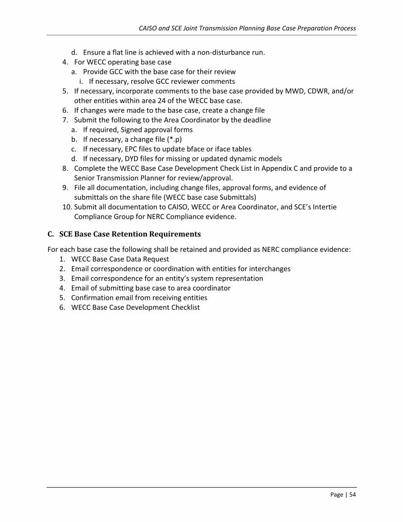
CAISO and SCE Joint Transmission Planning Base Case Preparation Process
Page | 54
d. Ensure a flat line is achieved with a non-disturbance run. 4. For WECC operating base case
a. Provide GCC with the base case for their review i. If necessary, resolve GCC reviewer comments
5. If necessary, incorporate comments to the base case provided by MWD, CDWR, and/or other entities within area 24 of the WECC base case.
6. If changes were made to the base case, create a change file 7. Submit the following to the Area Coordinator by the deadline
a. If required, Signed approval forms b. If necessary, a change file (*.p) c. If necessary, EPC files to update bface or iface tables d. If necessary, DYD files for missing or updated dynamic models
8. Complete the WECC Base Case Development Check List in Appendix C and provide to a Senior Transmission Planner for review/approval.
9. File all documentation, including change files, approval forms, and evidence of submittals on the share file (WECC base case Submittals)
10. Submit all documentation to CAISO, WECC or Area Coordinator, and SCE’s Intertie Compliance Group for NERC Compliance evidence.
C. SCE Base Case Retention Requirements
For each base case the following shall be retained and provided as NERC compliance evidence: 1. WECC Base Case Data Request 2. Email correspondence or coordination with entities for interchanges 3. Email correspondence for an entity’s system representation 4. Email of submitting base case to area coordinator 5. Confirmation email from receiving entities 6. WECC Base Case Development Checklist

CAISO and SCE Joint Transmission Planning Base Case Preparation Process
Page | 55
Appendix C
WECC Base Case Development Checklist
Below are key actions and procedures that are critical to developing base cases accurately and on a timely basis. Please make sure that you follow this checklist and indicate that you have completed the critical tasks outlined below for each Intertie Planning study for which you are responsible. The base case shall be reviewed and the completed checklist signed by a senior level planner (PSP4 and above) in IP as well as the assigned planner prior to being used for Intertie Planning studies. Also, specific ISO procedures and guidelines related to base case preparation shall be followed.
WECC Base Case Study Year and Season:
Type of Case: ☐ Planning Case ☐ Operating Case
☐ Initial Compilation ☐ Review Case Comments The responsible Planners shall sign this checklist to acknowledge that the activities identified in this checklist have been satisfactorily completed and the base case is acceptable for submittal to WECC staff. Assigned Planner: ______________________________ Date: __________ Senior IP Planner: ______________________________ Date: __________ Rev. 4 – K. Brooks 2016-06-01 Rev. 3 – J. Shearer 2013-02-12 Rev. 2 – M. Lotto 2012-04-02 Rev. 1 – J. Shearer 2012-03-16 Rev. 0 – S. Mavis 2011-10-21

CAISO and SCE Joint Transmission Planning Base Case Preparation Process
Page | 56
Base Case Preparation Checklist – As Applicable
☐ The Data Request Letter or Review Request Letter has been received from WECC
☐ Sub-Coordination or Review Comments have been received from PTOs and Non-PTOs within area 24 of the WECC base case.
List:
☐ Equipment Characteristics, System Data, and Interchange Schedules for steady-state modeling have been provided to WECC where applicable:
☐ Bus (Substation)
☐ Generating Units
☐ AC Transmission Lines or Circuits
☐ DC Transmission Lines
☐ Transformer (voltage and phase-shifting)
☐ Reactive Compensation (shunt and series capacitors and reactors)
☐ Interchange Schedules
☐ Equipment Characteristics and System Data for dynamic modeling have been provided to WECC
☐ New or Refurbished Excitation Systems Data
☐ Unit-Specific Dynamics Data for Generators and Synchronous Condensers
☐ Device Specific Dynamics Data for dynamic devices such as SVC, HVDC, and FACTS devices
☐ Dynamic Load Data
CAISO and SCE Joint Transmission Planning Base Case Preparation Process
Page | 57
WECC Data Preparation Manual – As Applicable
☐ Bus Guidelines
☐ Avoid duplication of bus names within same kV class
☐ Bus names and numbers consistent from case to case
☐ Bus numbers within designated ranges: 24000-25999, 29000-29999, 94000-95999, 240000-259999, 290000-299999
☐ Provide zone and owner numbers
☐ Generator Guidelines
☐ Minimize load netting, load netting shall be avoided.
☐ Pmax shall not be greater than the maximum capability of the governor (mwcap)
☐ Model single unit generators of 10 MVA or higher
☐ Model aggregate plant capacity of 20 MVA or higher connected via step-up transformer to 60-kV or higher
☐ Generator representation consistent between steady state and dynamic data (i.e., Bus Number, Bus Name, Bus Id, Bus Voltage)
☐ Delete retired generators that have been demolished from steady state and dynamic data
☐ Avoid remote regulation (more than one bus away)
☐ Set baseload flag to 2 for units unable to respond to low frequency with additional
mechanical power
☐ Enter Operating Pmin data accurately
☐ Pgen must fall within or at Pmin and Pmax
☐ AC Line or Circuit Guidelines
☐ Avoid equivalent transmission systems. Equivalent branches must have a circuit
ID of “eq” or “99”. If no line rating is available, use 9999 MVA.
☐ Model all transmission lines 115-kV and above except very low impedance lines (<0.00029)
☐ Exclude SCE lines not meeting Bulk Power System Definition
☐ Model any significant looped transmission less than 115-kV
☐ Model anticipated outages – operation base cases, obtain outage schedule from GCC
☐ Number line sections consecutively beginning with “1”

CAISO and SCE Joint Transmission Planning Base Case Preparation Process
Page | 58
☐ Avoid bus ties and low impedance lines where possible (i.e., greater than or equal to 0.00029)
☐ Include appropriate facility ratings, including normal & emergency ratings (8 Ratings)
☐ Transformer Guidelines
☐ Model TCUL transformers as such only with complete TCUL data (Automatic; type 2)
☐ TCUL Transformer maximum tap must be greater than minimum tap
☐ Maximum phase shift angle must be greater than minimum phase shift angle (Type 4)
☐ For manual tap changing (Type 1), voltage shall not exceed SOB-017 Voltage requirements
☐ Load Model Guidelines
☐ Model Load level to reflect the conditions and season of the case
☐ Model generators less than 10 MVA as load with ID “nt” that are load netted.
☐ Represent loads at the same bus as being in the same area as the bus
☐ Model generator station service load explicitly with an ID of “SS”
☐ Fixed Reactive Device Guidelines
☐ Explicitly model all fixed shunt elements
☐ Switched Reactive Device Guidelines
☐ Explicitly model all switchable shunt elements
☐ Area Interchange Guidelines
☐ Coordinate all transactions between areas (LADWP, PG&E, SDG&E, AZ, WAPA, MWD, IID, and CDWR)
☐ The sum of all area interchanges must be zero
☐ Master Tie Line File Guidelines
☐ Tie-Lines or paths are up to date in the IFACE and BFACE tables
☐ Do not change area numbers that represent a WECC member area
☐ Generation Dynamic Model Guidelines
☐ Submit Power System Stabilizer Data for generators equipped with PSS
☐ Load Dynamic Model Guidelines
☐ Include default area or zone dynamic load characteristics

CAISO and SCE Joint Transmission Planning Base Case Preparation Process
Page | 59
☐ 20% Induction Motor for loads >5 MW at load buses and >80 MW at generator buses
☐ Under Frequency Load Shedding Guidelines
☐ Include UFLS data that complies with WECC-coordinated off-nominal requirements
☐ Under Voltage Load Shedding Guidelines
☐ Include any UVLS records
☐ DC Lines, SVC, and D-VAR system Guidelines
☐ Model SVC systems to reflect actual performance
CAISO and SCE Joint Transmission Planning Base Case Preparation Process
Page | 60
Additional Base Case Preparation Guidelines – As Applicable Below are additional items SCE incorporates into WECC Base Cases as needed:
☐ CDWR Pump Load and Generation Forecast has been coordinated
☐ MWD Pump Load and Generation Forecast has been coordinated
☐ Coordinate with City of Anaheim, Azusa, Banning, Colton, Riverside, Vernon, and
Pasadena system representations
☐ Other Comments have been incorporated
List other Comments: ☐
All transmission projects approved by the ISO are modeled.
☐ All generation projects and related POS are modeled per DPM criteria for
developing WECC base cases (Refer to Appendix A) or study scope as applicable.
☐ SCE Sub-Transmission Load Forecast is modeled for the Sub-Transmission system.
☐ The load is modeled with the appropriate WATT/VAR ratio.
☐ Slack bus generators are in generation mode and fall within their respective Pmin
and Pmax values.
☐ All voltage profiles are at high-end operating levels and within limits
☐ The VAR flows between SCE and other utilities are within the SCE SOB 17
operating limits or within appropriate ranges.
☐ All thermal, voltage and stability results meet the appropriate performance
standards (NERC/WECC/ISO/SCE criteria including SCE SOB 17).
☐ Replog Items have been corrected or prevented
☐ Owner and Zone numbers are not 0 or 1
☐ The dyd data file matches the power flow base case and a non-disturbance run
results in a “Flat Line.”
☐ Signature Forms has been signed (if required by WECC) (Review Only)
☐ Grid Operations have reviewed the case (Review of Operating Case Only)
Checklist Deviations Please provide details as to the cause of the deviation(s) and the resolution below
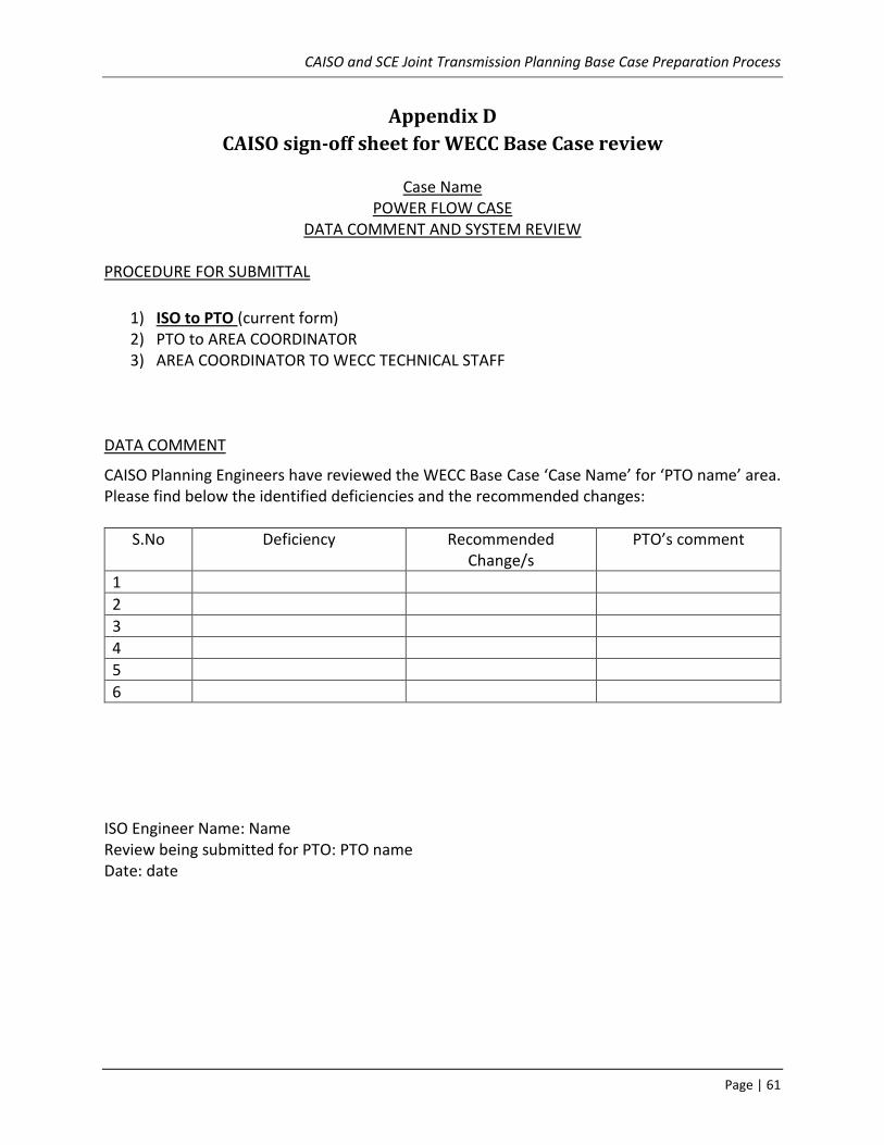
CAISO and SCE Joint Transmission Planning Base Case Preparation Process
Page | 61
Appendix D
CAISO sign-off sheet for WECC Base Case review
Case Name POWER FLOW CASE
DATA COMMENT AND SYSTEM REVIEW PROCEDURE FOR SUBMITTAL
1) ISO to PTO (current form) 2) PTO to AREA COORDINATOR 3) AREA COORDINATOR TO WECC TECHNICAL STAFF
DATA COMMENT CAISO Planning Engineers have reviewed the WECC Base Case ‘Case Name’ for ‘PTO name’ area. Please find below the identified deficiencies and the recommended changes:
S.No Deficiency Recommended Change/s
PTO’s comment
1
2
3
4
5
6
ISO Engineer Name: Name Review being submitted for PTO: PTO name Date: date

CAISO and SCE Joint Transmission Planning Base Case Preparation Process
Page | 62
Appendix E
Anchor Data Set (ADS)
For many years, WECC has been aware that data used in its various reliability assessment models (e.g., Power Flow-PF; Production Cost Model-PCM) has varying degrees of consistency and, to some extent, redundancy in terms of the data’s development and collection. The concept of an Anchor Data Set (ADS) has been created with the goal of providing a common starting point for WECC’s long-term reliability assessments, as well as other planning studies undertaken by WECC stakeholders. The process for developing the ADS is designed to eliminate redundant data development and collection while providing a mechanism for ensuring the accuracy, consistency and completeness of the data.
The Anchor Data Set (ADS) is typically a 10 year out Heavy Summer compilation of load, resource and transmission topology information used by the Western Planning Regions (WPRs) in their regional transmission plans as well as by other stakeholders in various planning analyses. This data is compatible with Production Cost Models (PCM) and power flow (PF) models, including dynamic data and associated assumptions. The ADS is comprised of data developed by NERC Registered Entities in the U.S. and international entities in the Western Interconnection (Balancing Authorities (BAs’), Transmission Planners (TPs’) and/or Planning Coordinators (PCs’)) and used by FERC Registered Entities in the U.S. that may be affiliated to the WPR whether or not they have FERC planning obligations as well as Transmission Owners (TO), Generation Owners (GO) or Load Serving Entities (LSE) not represented by the WPR or IPR.
The data included in the ADS must reflect applicable state and federal statutory public policy requirements such as Renewable Portfolio Standards (RPS). Resource and Transmission representation must be aligned with the most recent regional plan of the Planning Region. To achieve the goals of the ADS it is essential that the data submitted for the 10 year out Heavy Summer WECC Powerflow ADS case, as part of the MOD-032 process, is coordinated with the planning regions, with incremental change files and/or change log provided with reference to the changes being made to the WECC approved/provided 10 year out Heavy Summer seed case.
Please refer to WECC ADS Webpage5 for further information.
5 https://www.wecc.biz/SystemStabilityPlanning/Pages/AnchorDataSet.aspx