journal aes 2003 ene-feb vol 51, num 1-2
DESCRIPTION
Journal AES 2003 Ene-Feb Vol 51, Num 1-2TRANSCRIPT

sustainingmemberorganizations AESAES
VO
LU
ME
51,NO
.1/2JO
UR
NA
L O
F T
HE
AU
DIO
EN
GIN
EE
RIN
G S
OC
IET
Y2003 JA
NU
AR
Y/F
EB
RU
AR
Y
JOURNAL OF THE AUDIO ENGINEERING SOCIETYAUDIO / ACOUSTICS / APPLICATIONSVolume 51 Number 1/2 2003 January/February
The Audio Engineering Society recognizes with gratitude the financialsupport given by its sustaining members, which enables the work ofthe Society to be extended. Addresses and brief descriptions of thebusiness activities of the sustaining members appear in the Octoberissue of the Journal.
The Society invites applications for sustaining membership. Informa-tion may be obtained from the Chair, Sustaining Memberships Committee, Audio Engineering Society, 60 East 42nd St., Room2520, New York, New York 10165-2520, USA, tel: 212-661-8528.Fax: 212-682-0477.
ACO Pacific, Inc.Air Studios Ltd.AKG Acoustics GmbHAKM Semiconductor, Inc.Amber Technology LimitedAMS Neve plcATC Loudspeaker Technology Ltd.Audio LimitedAudiomatica S.r.l.Audio Media/IMAS Publishing Ltd.Audio Precision, Inc.AudioScience, Inc.Audio-Technica U.S., Inc.AudioTrack CorporationAutograph Sound Recording Ltd.B & W Loudspeakers LimitedBMP RecordingBritish Broadcasting CorporationBSS Audio Cadac Electronics PLCCalrec AudioCanford Audio plcCEDAR Audio Ltd.Celestion International LimitedCerwin-Vega, IncorporatedClearOne Communications Corp.Community Professional Loudspeakers, Inc.Crystal Audio Products/Cirrus Logic Inc.D.A.S. Audio, S.A.D.A.T. Ltd.dCS Ltd.Deltron Emcon LimitedDigidesignDigigramDigital Audio Disc CorporationDolby Laboratories, Inc.DRA LaboratoriesDTS, Inc.DYNACORD, EVI Audio GmbHEastern Acoustic Works, Inc.Eminence Speaker LLC
Event Electronics, LLCFerrotec (USA) CorporationFocusrite Audio Engineering Ltd.Fostex America, a division of Foster Electric
U.S.A., Inc.Fraunhofer IIS-AFreeSystems Private LimitedFTG Sandar TeleCast ASHarman BeckerHHB Communications Ltd.Innova SONInnovative Electronic Designs (IED), Inc.International Federation of the Phonographic
IndustryJBL ProfessionalJensen Transformers Inc.Kawamura Electrical LaboratoryKEF Audio (UK) LimitedKenwood U.S.A. CorporationKlark Teknik Group (UK) PlcKlipsch L.L.C.Laboratories for InformationL-Acoustics USLeitch Technology CorporationLindos ElectronicsMagnetic Reference Laboratory (MRL) Inc.Martin Audio Ltd.Meridian Audio LimitedMetropolis GroupMiddle Atlantic Products Inc.Mosses & MitchellM2 Gauss Corp.Music Plaza Pte. Ltd.Georg Neumann GmbH Neutrik AGNVisionNXT (New Transducers Ltd.)1 LimitedOntario Institute of Audio Recording
TechnologyOutline sncPacific Audio-VisualPRIMEDIA Business Magazines & Media Inc.
Prism SoundPro-Bel LimitedPro-Sound NewsRadio Free AsiaRane CorporationRecording ConnectionRocket NetworkRoyal National Institute for the BlindRTI Tech Pte. Ltd.Rycote Microphone Windshields Ltd.SADiESanctuary Studios Ltd.Sekaku Electron Ind. Co., Ltd.Sennheiser Electronic CorporationShure Inc.Snell & Wilcox Ltd.Solid State Logic, Ltd.Sony Broadcast & Professional EuropeSound Devices LLCSound On Sound Ltd.Soundcraft Electronics Ltd.Soundtracs plcSowter Audio TransformersSRS Labs, Inc.Stage AccompanySterling Sound, Inc.Studer North America Inc.Studer Professional Audio AGTannoy LimitedTASCAMTHAT CorporationTOA Electronics, Inc.Touchtunes Music Corp.United Entertainment Media, Inc.Uniton AGUniversity of DerbyUniversity of SalfordUniversity of Surrey, Dept. of Sound
RecordingVidiPaxWenger CorporationJ. M. Woodgate and AssociatesYamaha Research and Development
In this issue…
Room Equalization Methods
Kautz Filter Techniques
Horn Acoustics
Audio Coding and Error Concealment
Features…
114th ConventionAmsterdam—Preview
Virtual and Synthetic Audio
115th Convention, New York—Call for Papers

AUDIO ENGINEERING SOCIETY, INC.INTERNATIONAL HEADQUARTERS
60 East 42nd Street, Room 2520, New York, NY 10165-2520, USATel: +1 212 661 8528 . Fax: +1 212 682 0477E-mail: [email protected] . Internet: http://www.aes.org
Roger K. Furness Executive DirectorSandra J. Requa Executive Assistant to the Executive Director
ADMINISTRATION
STANDARDS COMMITTEE
GOVERNORS
OFFICERS 2002/2003
Karl-Otto BäderCurtis HoytRoy Pritts
Don PuluseDavid Robinson
Annemarie StaepelaereRoland Tan
Kunimara Tanaka
Ted Sheldon Chair Dietrich Schüller Vice Chair
Mendel Kleiner Chair Mark Ureda Vice Chair
SC-04-01 Acoustics and Sound Source Modeling Richard H. Campbell, Wolfgang Ahnert
SC-04-02 Characterization of Acoustical MaterialsPeter D’Antonio, Trevor J. Cox
SC-04-03 Loudspeaker Modeling and Measurement David Prince, Neil Harris, Steve Hutt
SC-04-04 Microphone Measurement and CharacterizationDavid Josephson, Jackie Green
SC-04-07 Listening Tests: David Clark, T. Nousaine
SC-06-01 Audio-File Transfer and Exchange Mark Yonge, Brooks Harris
SC-06-02 Audio Applications Using the High Performance SerialBus (IEEE: 1394): John Strawn, Bob Moses
SC-06-04 Internet Audio Delivery SystemKarlheinz Brandenburg
SC-06-06 Audio MetadataC. Chambers
Kees A. Immink President
Ronald Streicher President-Elect
Garry Margolis Past President
Jim Anderson Vice President Eastern Region, USA/Canada
James A. Kaiser Vice PresidentCentral Region, USA/Canada
Bob Moses Vice President,Western Region, USA/Canada
Søren Bech Vice PresidentNorthern Region, Europe
Markus ErneVice President, Central Region, Europe
Daniel Zalay Vice President, Southern Region, Europe
Mercedes Onorato Vice President,Latin American Region
Neville ThieleVice President, International Region
Han Tendeloo Secretary
Marshall Buck Treasurer
TECHNICAL COUNCIL
Wieslaw V. Woszczyk ChairJürgen Herre and
Robert Schulein Vice Chairs
COMMITTEES
SC-02-01 Digital Audio Measurement Techniques Richard C. Cabot, I. Dennis, M. Keyhl
SC-02-02 Digital Input-Output Interfacing: Julian DunnRobert A. Finger, John Grant
SC-02- 05 Synchronization: Robin Caine
John P. Nunn Chair Robert A. Finger Vice Chair
Robin Caine Chair Steve Harris Vice Chair
John P. NunnChair
John WoodgateVice Chair
Bruce OlsonVice Chair, Western Hemisphere
Mark YongeSecretary, Standards Manager
Yoshizo Sohma Vice Chair, International
SC-02 SUBCOMMITTEE ON DIGITAL AUDIO
Working Groups
SC-03 SUBCOMMITTEE ON THE PRESERVATION AND RESTORATIONOF AUDIO RECORDING
Working Groups
SC-04 SUBCOMMITTEE ON ACOUSTICS
Working Groups
SC-06 SUBCOMMITTEE ON NETWORK AND FILE TRANSFER OF AUDIO
Working Groups
TECHNICAL COMMITTEES
SC-03-01 Analog Recording: J. G. McKnight
SC-03-02 Transfer Technologies: Lars Gaustad, Greg Faris
SC-03-04 Storage and Handling of Media: Ted Sheldon, Gerd Cyrener
SC-03-06 Digital Library and Archives Systems: William Storm Joe Bean, Werner Deutsch
SC-03-12 Forensic Audio: Tom Owen, M. McDermottEddy Bogh Brixen
TELLERSChristopher V. Freitag Chair
WOMEN IN AUDIOKees A. Immink Chair
Correspondence to AES officers and committee chairs should be addressed to them at the society’s international headquarters.
Ray Rayburn Chair John Woodgate Vice Chair
SC-05-02 Audio ConnectorsRay Rayburn, Werner Bachmann
SC-05-03 Audio Connector DocumentationDave Tosti-Lane, J. Chester
SC-05-05 Grounding and EMC Practices Bruce Olson, Jim Brown
SC-05 SUBCOMMITTEE ON INTERCONNECTIONS
Working Groups
ACOUSTICS & SOUNDREINFORCEMENT
Mendel Kleiner ChairKurt Graffy Vice Chair
ARCHIVING, RESTORATION ANDDIGITAL LIBRARIES
David Ackerman Chair
AUDIO FORTELECOMMUNICATIONS
Bob Zurek ChairAndrew Bright Vice Chair
CODING OF AUDIO SIGNALSJames Johnston and
Jürgen Herre Cochairs
AUTOMOTIVE AUDIORichard S. Stroud Chair
Tim Nind Vice Chair
HIGH-RESOLUTION AUDIOMalcolm Hawksford Chair
Vicki R. Melchior andTakeo Yamamoto Vice Chairs
LOUDSPEAKERS & HEADPHONESDavid Clark Chair
Juha Backman Vice Chair
MICROPHONES & APPLICATIONSDavid Josephson Chair
Wolfgang Niehoff Vice Chair
MULTICHANNEL & BINAURALAUDIO TECHNOLOGIESFrancis Rumsey Chair
Gunther Theile Vice Chair
NETWORK AUDIO SYSTEMSJeremy Cooperstock ChairRobert Rowe and Thomas
Sporer Vice Chairs
AUDIO RECORDING & STORAGESYSTEMS
Derk Reefman Chair
PERCEPTION & SUBJECTIVEEVALUATION OF AUDIO SIGNALS
Durand Begault ChairSøren Bech and Eiichi Miyasaka
Vice Chairs
SIGNAL PROCESSINGRonald Aarts Chair
James Johnston and Christoph M.Musialik Vice Chairs
STUDIO PRACTICES & PRODUCTIONGeorge Massenburg Chair
Alan Parsons, David Smith andMick Sawaguchi Vice Chairs
TRANSMISSION & BROADCASTINGStephen Lyman Chair
Neville Thiele Vice Chair
AWARDSRoy Pritts Chair
CONFERENCE POLICYSøren Bech Chair
CONVENTION POLICY & FINANCEMarshall Buck Chair
EDUCATIONDon Puluse Chair
FUTURE DIRECTIONSKees A. Immink Chair
HISTORICALJ. G. (Jay) McKnight Chair
Ted Sheldon Vice ChairDonald J. Plunkett Chair Emeritus
LAWS & RESOLUTIONSRon Streicher Chair
MEMBERSHIP/ADMISSIONSFrancis Rumsey Chair
NOMINATIONSGarry Margolis Chair
PUBLICATIONS POLICYRichard H. Small Chair
REGIONS AND SECTIONSSubir Pramanik Chair
STANDARDSJohn P. Nunn Chair

AES Journal of the Audio Engineering Society(ISSN 0004-7554), Volume 51, Number 1/2, 2003 January/FebruaryPublished monthly, except January/February and July/August when published bi-monthly, by the Audio Engineering Society, 60 East 42nd Street, New York, NewYork 10165-2520, USA, Telephone: +1 212 661 8528. Fax: +1 212 682 0477. E-mail: [email protected]. Periodical postage paid at New York, New York, and at anadditional mailing office. Postmaster: Send address corrections to Audio Engineer-ing Society, 60 East 42nd Street, New York, New York 10165-2520.
The Audio Engineering Society is not responsible for statements made by itscontributors.
COPYRIGHTCopyright © 2003 by the Audio Engi-neering Society, Inc. It is permitted toquote from this Journal with custom-ary credit to the source.
COPIESIndividual readers are permitted tophotocopy isolated ar ticles forresearch or other noncommercial use.Permission to photocopy for internalor personal use of specific clients isgranted by the Audio EngineeringSociety to libraries and other usersregistered with the Copyright Clear-ance Center (CCC), provided that thebase fee of $1.00 per copy plus $0.50per page is paid directly to CCC, 222Rosewood Dr., Danvers, MA 01923,USA. 0004-7554/95. Photocopies ofindividual articles may be orderedfrom the AES Headquarters office at$5.00 per article.
REPRINTS AND REPUBLICATIONMultiple reproduction or republica-tion of any material in this Journal requires the permission of the AudioEngineering Society. Permissionmay also be required from the author(s). Send inquiries to AES Edi-torial office.
SUBSCRIPTIONSThe Journal is available by subscrip-tion. Annual rates are $180.00 surfacemail, $225.00 air mail. For information,contact AES Headquarters.
BACK ISSUESSelected back issues are available:From Vol. 1 (1953) through Vol. 12(1964), $10.00 per issue (members),$15.00 (nonmembers); Vol. 13 (1965)to present, $6.00 per issue (members),$11.00 (nonmembers). For informa-tion, contact AES Headquarters office.
MICROFILMCopies of Vol. 19, No. 1 (1971 Jan-uary) to the present edition are avail-able on microfilm from University Microfilms International, 300 NorthZeeb Rd., Ann Arbor, MI 48106, USA.
ADVERTISINGCall the AES Editorial office or send e-mail to: [email protected].
MANUSCRIPTSFor information on the presentationand processing of manuscripts, seeInformation for Authors.
Patricia M. Macdonald Executive EditorWilliam T. McQuaide Managing EditorGerri M. Calamusa Senior EditorAbbie J. Cohen Senior EditorMary Ellen Ilich Associate EditorPatricia L. Sarch Art Director
EDITORIAL STAFF
Europe ConventionsZevenbunderslaan 142/9, BE-1190 Brussels, Belgium, Tel: +32 2 3457971, Fax: +32 2 345 3419, E-mail for convention information:[email protected] ServicesB.P. 50, FR-94364 Bry Sur Marne Cedex, France, Tel: +33 1 4881 4632,Fax: +33 1 4706 0648, E-mail for membership and publication sales:[email protected] KingdomBritish Section, Audio Engineering Society Ltd., P. O. Box 645, Slough,SL1 8BJ UK, Tel: +441628 663725, Fax: +44 1628 667002,E-mail: [email protected] Japan Section, 1-38-2 Yoyogi, Room 703, Shibuyaku-ku, Tokyo 151-0053, Japan, Tel: +81 3 5358 7320, Fax: +81 3 5358 7328, E-mail: [email protected].
PURPOSE: The Audio Engineering Society is organized for the purposeof: uniting persons performing professional services in the audio engi-neering field and its allied arts; collecting, collating, and disseminatingscientific knowledge in the field of audio engineering and its allied arts;advancing such science in both theoretical and practical applications;and preparing, publishing, and distributing literature and periodicals rela-tive to the foregoing purposes and policies.MEMBERSHIP: Individuals who are interested in audio engineering maybecome members of the Society. Applications are considered by the Ad-missions Committee. Grades and annual dues are: Full member, $80.00;Associate member, $80.00; Student member, $40.00. A membership appli-cation form may be obtained from headquarters. Sustaining membershipsare available to persons, corporations, or organizations who wish to supportthe Society. A subscription to the Journal is included with all memberships.
Ronald M. AartsJames A. S. AngusGeorge L. AugspurgerJeffrey BarishJerry BauckJames W. BeauchampSøren BechDurand BegaultBarry A. BlesserJohn S. BradleyRobert Bristow-JohnsonJohn J. BubbersMarshall BuckMahlon D. BurkhardRichard C. CabotEdward M. CherryRobert R. CordellAndrew DuncanJohn M. EargleLouis D. FielderEdward J. Foster
Mark R. GanderEarl R. GeddesDavid GriesingerMalcolm O. J. HawksfordJürgen HerreTomlinson HolmanAndrew HornerJames D. JohnstonArie J. M. KaizerJames M. KatesD. B. Keele, Jr.Mendel KleinerDavid L. KlepperW. Marshall Leach, Jr.Stanley P. LipshitzRobert C. MaherDan Mapes-RiordanJ. G. (Jay) McKnightGuy W. McNallyD. J. MearesRobert A. MoogJames A. MoorerDick Pierce
Martin PolonD. PreisFrancis RumseyKees A. Schouhamer
ImminkManfred R. SchroederRobert B. SchuleinRichard H. SmallJulius O. Smith IIIGilbert SoulodreHerman J. M. SteenekenJohn StrawnG. R. (Bob) ThurmondJiri TichyFloyd E. TooleEmil L. TorickJohn VanderkooyDaniel R. von
RecklinghausenRhonda WilsonJohn M. WoodgateWieslaw V. Woszczyk
REVIEW BOARD
Flávia Elzinga AdvertisingIngeborg M. StochmalCopy Editor
Barry A. BlesserConsulting Technical Editor
Stephanie Paynes Writer
Daniel R. von Recklinghausen Editor
Eastern Region, USA/CanadaSections: Atlanta, Boston, District of Columbia, New York, Philadelphia, TorontoStudent Sections: American University, Berklee College of Music, CarnegieMellon University, Duquesne University, Fredonia, Full Sail Real WorldEducation, Hampton University, Institute of Audio Research, McGillUniversity, Peabody Institute of Johns Hopkins University, Pennsylvania StateUniversity, University of Hartford, University of Massachusetts-Lowell,University of Miami, University of North Carolina at Asheville, WilliamPatterson University, Worcester Polytechnic UniversityCentral Region, USA/CanadaSections: Central Indiana, Chicago, Detroit, Kansas City, Nashville, NewOrleans, St. Louis, Upper Midwest, West MichiganStudent Sections: Ball State University, Belmont University, ColumbiaCollege, Michigan Technological University, Middle Tennessee StateUniversity, Music Tech College, SAE Nashville, Northeast CommunityCollege, Ohio University, Ridgewater College, Hutchinson Campus,Southwest Texas State University, University of Arkansas-Pine Bluff,University of Cincinnati, University of Illinois-Urbana-ChampaignWestern Region, USA/CanadaSections: Alberta, Colorado, Los Angeles, Pacific Northwest, Portland, San Diego, San Francisco, Utah, VancouverStudent Sections: American River College, Brigham Young University,California State University–Chico, Citrus College, Cogswell PolytechnicalCollege, Conservatory of Recording Arts and Sciences, Denver, ExpressionCenter for New Media, Long Beach City College, San Diego State University,San Francisco State University, Cal Poly San Luis Obispo, Stanford University,The Art Institute of Seattle, University of Southern California, VancouverNorthern Region, Europe Sections: Belgian, British, Danish, Finnish, Moscow, Netherlands, Norwegian, St. Petersburg, SwedishStudent Sections: All-Russian State Institute of Cinematography, Danish,Netherlands, St. Petersburg, University of Lulea-PiteaCentral Region, EuropeSections: Austrian, Belarus, Czech, Central German, North German, South German, Hungarian, Lithuanian, Polish, Slovakian Republic, Swiss,UkrainianStudent Sections: Aachen, Berlin, Czech Republic, Darmstadt, Detmold,Düsseldorf, Graz, Ilmenau, Technical University of Gdansk (Poland), Vienna,Wroclaw University of TechnologySouthern Region, EuropeSections: Bosnia-Herzegovina, Bulgarian, Croatian, French, Greek, Israel,Italian, Portugal, Romanian, Slovenian, Spanish, Turkish, YugoslavianStudent Sections: Croatian, Conservatoire de Paris, Italian, Louis-Lumière SchoolLatin American Region Sections: Argentina, Brazil, Chile, Colombia (Medellin), Mexico, Uruguay,VenezuelaStudent Sections: Taller de Arte Sonoro (Caracas)International RegionSections: Adelaide, Brisbane, Hong Kong, India, Japan, Korea, Malaysia,Melbourne, Philippines, Singapore, Sydney
AES REGIONAL OFFICES
AES REGIONS AND SECTIONS

AES JOURNAL OF THE
AUDIO ENGINEERING SOCIETY
AUDIO/ACOUSTICS/APPLICATIONS
VOLUME 51 NUMBER 1/2 2003 JANUARY/FEBRUARY
CONTENT
PAPERSAnalysis of Traditional and Reverberation-Reducing Methods of Room Equalization...........................................................................................................................................Louis D. Fielder 3Unlike the traditional approach to room equalization, which compensates for the steady-state spectral effects, a true equalization method will become a dereverberator. Such an approach simultaneously removes the acoustic properties of the reproduction environment in both the frequency and time domains. It is a very difficult problem. Although the proposed solution proves to be impractical when employed in a real application, the analysis illuminates several critical criteria for evaluating any solution. New psychoacoustic metrics successfully predicted those degradations that made the system unacceptable.
Kautz Filters and Generalized Frequency Resolution:Theory and Audio Applications.........................................................................................................Tuomas Paatero and Matti Karjalainen 27Most audio signal processing filters use a basic building block containing a delay or a pole, but other choices of orthonormal functions include the use of an all-pass block. When using this type of block, the resulting structures, called Kautz filters, readily allow frequency warping. Although this approach has been overshadowed by the more traditional methods, the authors show that lower order filters are needed when applied to loudspeaker equalization, room response modeling, and guitar body acoustics. The design phase is more complex, but there is no additional computation load at run time.
Horn Acoustics: Calculation through the Horn Cutoff Frequency................................Peter A. Fryer 45The author reconsiders the mathematical approach to analyzing exponential horn loudspeakers above and below the cutoff frequency. This work provides a more solid foundation for the simplified methods of partitioning the mathematics into two regions with different assumptions in each one. By introducing a tiny amount of acoustic loss into the model, the mathematics no longer break down when traversing the transition region at cutoff. The results agree with measured data.
Modified Discrete Cosine Transform—Its Implications for Audio Coding and Error Concealment...........................................................................................................................................Ye Wang and Miikka Vilermo 52This study of the modified discrete cosine transform (MDCT) explores the implications of audio coding and error concealment from the perspective of Fourier frequency analysis. Subjective coding quality and the tolerance to missing or repeated compressed data blocks often produce contradictory requirements in real applications. Tradeoffs involve the selection of window-sized crossfade transitions between blocks and perception of uncancelled alias components.
CORRECTIONSCorrection to: “On the Use of Time–Frequency Reassignment in Additive Sound Modeling”.....................................................................................................................Kelly Fitz and Lippold Haken 62
STANDARDS AND INFORMATION DOCUMENTSAES Standards Committee News ........................................................................................................... 63MADI; loudspeaker components; peak flutter; tape storage; CD-ROM life; loudspeaker polar data; digi-tal input-output interfacing; digital synchronization; media storage and handling; library and archivesystems; forensic audio; audio connectors; shielding and EMC; audio over IEEE 1394
FEATURES114th Convention Preview, Amsterdam................................................................................................. 76
Calendar ................................................................................................................................................. 78Exhibitors............................................................................................................................................... 79Exhibit Previews.................................................................................................................................... 81
Virtual and Synthetic Audio ................................................................................................................... 93115th Convention, New York, Call for Papers........................................................................................ 112
DEPARTMENTS News of the Sections ..........................................99Upcoming Meetings ..........................................104Sound Track........................................................105Available Literature ...........................................106Membership Information...................................108
Advertiser Internet Directory............................109In Memoriam ......................................................111Sections Contacts Directory ............................114AES Conventions and Conferences ................120

PAPERS
0 INTRODUCTION
The use of electronic filtering or equalization toimprove the subjective quality of sound reproduction vialoudspeakers in a room has enjoyed widespread use overthe last four decades, with an early example described byBoner and Boner [1]. This is particularly true for profes-sional sound reproduction applications in cinemas, mixingrooms, and large sound venues.
Equalization is useful in improving the overall per-ceived quality in sound reproduction applications but hasa number of important limitations. These include theinability to provide accurate timbre matches between dif-ferent environments and to measure or correct for exactlywhat the listener perceives. Additional limitations are theneed to equalize to a nonflat frequency response target forbest subjective results and the difficulty in equalizing overa wide area of listening positions. Holman [2], Schulein[3], and Staffeldt and Rasmussen [4] have reported someof these problems and investigated solutions, but unfortu-nately the problems still remain largely unsolved.
Despite the success and widespread use of the tradi-tional equalization methods, the previously mentionedproblems argue strongly for further work in this field, inparticular because of the advent of extremely powerfuldigital signal processing (DSP) technology. These DSPadvances have led to the interest in more complex meth-ods of equalization, some incorporating room dereverber-ation or room transfer function inversion methods. Thispaper will examine whether the use of dereverberation via
digital signal processing provides an effective solution toequalization problems.
The process of loudspeaker–room equalization will bedescribed for both the traditional and the more complexsituations incorporating reverberation reduction, calledreverberation-reducing equalization. Reverberation reduc-tion of the transfer function of a particular professionallistening-room environment will be performed and thecharacteristics of this equalization examined as an exam-ple. In addition the consequences of physical displace-ments, time-varying loudspeaker–room characteristics,and impulse response measurement inaccuracies will beexamined.
Psychoacoustically derived criteria will be developed todetermine the audible consequences of dereverberationerrors. These criteria will incorporate the temporal inte-gration and masking properties of the ear. Simultaneous,backward, and forward masking concepts will beemployed to generate a simplified set of rules for deter-mining the audibility of sound components.
The group-delay characteristics derived from the phaseterm of the discrete Fourier transform (DFT) of the loud-speaker–room impulse response will be shown to be veryuseful in assessing the difficulty for dereverberation. Anumber of listening room and cinema environments willbe examined in this way.
Although one-dimensional loudspeaker–room transferfunctions, that is, the transfer function from one loud-speaker to one position in the room, are explored in thisstudy, the problems extend to the multidimensional case,where multiple loudspeakers and listening positions areconsidered. Since DSP methods are employed, 48-kHzsampled PCM signals and associated z-transforms arecombined with analog signal concepts.
J. Audio Eng. Soc., Vol. 51, No. 1/2, 2003 January/February 3
Analysis of Traditional and Reverberation-ReducingMethods of Room Equalization*
LOUIS D. FIELDER, AES Fellow
Dolby Laboratories Inc., San Francisco, CA 94103, USA
Traditionally, electronic equalization has used linear filters of low complexity. The natureof spectral and temporal distortions of rooms limits useful equalization to minimum-phasefilters of relatively low order, despite the existence of new and powerful digital signalprocessing tools. The high Q and non-minimum-phase nature of the room–loud-speaker–listener transfer function, caused by wave interference effects, creates severeproblems for more complete equalization. A typical professional listening room and threecinema acoustic environments were used to investigate the difficulties inherent for moreambitious equalization approaches.
* Presented at the 111th Convention of the Audio EngineeringSociety, New York, 2001 September 21–24; revised 2002January 2 and August 12.

FIELDER PAPERS
1 EQUALIZATION PROCESS
The equalization of a loudspeaker–room combinationat a single point is modeled by a filtering process in whichthe input signal is modified by two filters, the first repre-senting the transfer function of the loudspeaker–roomcombination and the second the equalization system.
A block diagram of an equalization filter combinedwith sound reproduction to a single point (represented bya microphone) is shown in Fig. 1. For the purposes ofthis analysis the characteristics of the microphone trans-fer function will be included in the loudspeaker–roomcharacteristic.
The filtering process is given by
w n c n h n u n 7 7^ ^ ^ ^h h h h (1)
where ⊗ represents the linear convolution product and
u(n) sampled input signalh(n) impulse response of equalization filterc(n) impulse response of loudspeaker–room–
microphone combinationw(n) reproduced signaln sample number representing sampled increments
in time.
Eq. (1) shows that the resultant time-domain character-istic of the reproduced signal is the original loud-speaker–room impulse response after it has been smearedin time by convolution with the equalization filter. Exceptin the special case where the equalization filter acts toreduce reverberation, the effect of the equalization filter isto extend and complicate the resultant impulse response.This time-smearing effect may cause audible time-domainproblems if the equalization filter has an impulse responsethat is too extended in time.
The equalization process can also be examined from thefrequency-domain point of view. In this case the spectralvalues from the DFT are used to gain a better understand-ing or to simplify the processing. This is a usefulapproach, but it has the added complication that the DFTis a block-based process, which causes the convolution itmodels to be circular, rather than linear, as explained inOppenheim et al. [5]. Occasionally this difference willhave significant consequences, so long block lengths areemployed to minimize it. When the block length isselected to be a power of 2, the DFT is replaced with amore efficient implementation, called the fast Fouriertransform (FFT).
The variables of Eq. (1) are then transformed by theDFT into the following complex variables as a function ofthe DFT frequency index:
U(k) DFT(u(n)) spectral values for input signalH(k) DFT(h(n)) spectral response of equaliza-
tion filterC(k) DFT(c(n)) spectral response of loudspeaker–
room–microphone combinationV(k) DFT(v(n)) spectrum of equalized signal
to loudspeakerW(k) DFT(w(n)) spectrum of reproduced signal
with k being the frequency index spanning the range of 0–48 000 Hz.
In the frequency domain the filtering process is a sim-ple multiplication relation,
.W k C k H k U k^ ^ ^ ^h h h h (2)
The frequency-sampled magnitude and phase for theappropriate transfer functions are derived from the realand imaginary parts of these variables.
1.1 Traditional EqualizationTraditionally equalization has been achieved via arrays
of first- and second-order analog filters to match the meas-ured steady-state magnitude of the loudspeaker–roomtransfer function to a target frequency response. Two com-mon approaches have been used. The first was the use offractional-octave filters, typically one-third octave, com-bined with a spectrum analyzer of similar bandwidth. SeeGreiner and Schoessow [6] and Bohn [7] for details on theimplementation of such equalizers. A second approachwas the use of parametric filters, which have variable cen-ter frequencies, frequency widths, and attenuation orrejection amounts. In this situation the spectrum analysismethod used varying bandwidths to match the capabilitiesof the parametric equalizer.
Since the loudspeaker–room transfer function is sub-stantially more complex than the analysis and equaliza-tion filters, the effect of this type of equalization is to gen-tly shape it to the desired response target. This approachhas the advantage of generating filters with short impulseresponse functions, which means that they are much lesslikely to create time-domain problems than the muchmore complex filters used in reverberation reduction orremoval. Unfortunately this simplicity comes at the costof not permitting the removal of all undesirable roomcharacteristics.
Existing practice has generally employed minimum-phase equalization, as described by Bohn [8], whichforces the equalization filter impulse response to be causalin nature, having zero elements for the time interval beforethe zero delay instant. This minimum-phase propertyreduces the listener’s sensitivity to room–equalizer mis-matches because errors are propagated forward (ratherthan backward) in time, making them more likely to bemasked and therefore less audible.
Consider the one-third-octave equalization of a profes-sional listening room with a reverberation time of 230 ms.
4 J. Audio Eng. Soc., Vol. 51, No. 1/2, 2003 January/February
Fig. 1. Block diagram of microphone–loudspeaker–room equal-izer combination.
equalizationfilterh(n)
room micc(n)
loudspeaker
input signalu(n)
reproducedsignal w(n)
equalizedsignal v(n)

PAPERS ROOM EQUALIZATION
Fig. 2 displays the spectral characteristics of the loud-speaker–room combination compared to its one-third-octave approximation.
Fig. 2 demonstrates that an equalization process whichflattens the one-third-octave response does not remove themajority of the response deviations of the room. Theresponse curve of the one-third-octave approximation hasa smoothly varying magnitude versus frequency, whereasthe loudspeaker–room characteristic has a magnitude ver-sus frequency curve with hundred of spectral notches andpeaks of very narrow bandwidth.
Fig. 3 compares the time-domain characteristics of thesame loudspeaker–room combination to those of its one-third-octave minimum-phase equalization filter. The twotime-domain responses are offset vertically for clarity.
Examination of Fig. 3 indicates that the loudspeaker–room impulse response is significantly more complex andpossesses much higher relative levels of ringing comparedto its one-third-octave minimum-phase equalization filter.The equalization filter time response is essentially animpulse of less than 1 ms in length, followed by low-levelringing at low frequencies, starting at 40 dB relative tothe primary peak and rapidly decaying to 90 dB within70 ms. As before, the loudspeaker– room impulseresponse has a complex structure, with its impulseresponse starting at only 15 dB relative to the maximumand then taking at least 200 ms to decay to the 80-dBlevel.
The difference in complexity and response durationbetween the equalization filter and the loudspeaker–roomresponse has important effects on the performance of theequalization. As mentioned before, the simplicity of theequalization function reduces the chance that any mis-match between the equalization and the loudspeaker–room response will have adverse time-domain conse-quences. The disadvantage of the traditional approach isthat the equalized frequency and time responses are verydifferent from a simple time-delay transfer function.Conversion to that ideal would result in a flat spectralmagnitude and a single impulse with a time delay. Thismeans that traditional equalization works best for steady-state sounds, but the inability to correct for time-domaineffects significantly limits its effectiveness for time-varying signals.
Successful implementations of equalization must alsoaccount for the frequent need to equalize the sound basedon a compromise over a larger area, rather than at a singlepoint in space. In particular it is necessary to account forthe fact that listeners have two ears. The common solutionto this is to use spatial averaging by placing multipleomnidirectional microphones at different locations withinthe listening environment and rms averaging of the mag-nitude spectra. Examples of spatial averaging in the auto-motive world are discussed in Geddes [9] and in the cin-ema environment in the SMPTE standard 202M [10].
1.2 Reverberation-Reducing EqualizationThe reverberation-reducing equalization model is much
more ambitious than the traditional equalization para-digm. It attempts to remove components defined as unde-
sirable by the equalization paradigm in a loudspeaker–room transfer function for completely flexible tailoring ofthe sound environment for the listener. If realizable, this isan extremely attractive idea because it implies completeflexibility in modifying the perceived sound.
The most basic form of reverberation-reducing equal-ization is the combination of a complete or partial dere-verberation process with the addition of desired transferfunction components. The process is divided into threesteps: separation of undesired transfer function compo-nents from the loudspeaker–room transfer function; dere-verberation of these undesirable components; and theaddition of new, but desired components.
The feasibility of reverberation-reducing equalizationwill be investigated by considering the dereverberationprocess in more detail. Dereverberation converts unde-sired elements of the transfer function into an impulseappropriately delayed in time, as denoted by
δw n u n m n m ^ ^ ^h h h (3)
where
δ(n) unit impulse function at sample zerou(n) sampled input signalm appropriate time delay in samples.
J. Audio Eng. Soc., Vol. 51, No. 1/2, 2003 January/February 5
Fig. 3. Comparison of time-domain characteristics of loud-speaker–room combination and its one-third-octave equalizationfilter.
0 50 100 150 200 250 300 350
1/3 octaveinverse
loudspeaker-room
50 dB
Level(dB)
Time (ms)
Fig. 2. Comparison of spectral magnitude of loudspeaker–roomcombination and its one-third-octave simplification.
20 100 1000 10000-40
-30
-20
-10
0
10
1/3 octaveapproximation
loudspeaker-room
Gain(dB)
Frequency (Hz)

FIELDER PAPERS
The measure of the feasibility of a reverberation-reduction equalization scheme is highly dependent on theability to dereverberate some or all of a real loudspeaker–room transfer function for a practical listening situation.For purposes of this study, dereverberation of the entiretransfer function will be examined. In this situation anexact inversion filter cancels all but the direct-arrivalimpulse from the loudspeaker–room transfer function,resulting in the original source signal without any roomeffects. Early workers in this field were Neely and Allen[11], who first investigated the invertibility of room trans-fer functions.
Dereverberation has proven difficult to implement. As aresult various approaches have been tried by those work-ing in the field.
1) Use of a gain limitation method called regularization,as explained by Kirkeby and Nelson [12]
2) Use of minimum-phase approximation, as exploredby Radlovic and Kennedy [13]
3) Employment of multiple channels, as investigated byNelson et al. [14] and Kirkeby et al. [15]
4) Attempting dereverberation over only part of theaudio frequency band, as proposed by Johansen andRubak [16], [17]
5) Minimum-phase approximation, attempting derever-beration over only part of the audio frequency band, use ofvarying degrees of spectral averaging as a function of fre-quency, and attempted separation or correction of thedirect-arrival sounds from the loudspeaker, as proposed byGenereux [18].
These approaches should be examined later, in light ofthe results shown in Sections 4 and 5. Due to the nature ofthe reverberation-reducing process, finding a spatial com-promise is much more difficult than for traditional meth-ods. Since the removal of sound components depends onan exact match between acoustic and equalization transferfunctions, any variation quickly prevents the subtractionof sound elements. Multidimensional dereverberationapproaches have been used in an attempt to alleviate thisproblem (see Nelson et al. [14] and Kirkeby et al. [15]). Inthis scenario each loudspeaker is used to dereverberate thesound at a particular point in space. Equalization over thelarger listening area is accomplished by spacing thesedereverberated points within that space so that the areabetween them provides acceptable equalization perform-ance. No attempt to find a single compromise transferfunction is made.
2 FFT-BASED DEREVERBERATION
Dereverberation is defined as the process that generatesan exact inverse of the loudspeaker–room transfer func-tion such that Eq. (3) is satisfied. It attempts to decon-volve the loudspeaker–room effects from the originalsignal u(n). Two approaches have been used to accom-plish dereverberation. The first approach replaces theconvolution filtering process by an equivalent matrixoperation and performs deconvolution through matrixinversion. The second transforms the loudspeaker–roomtransfer function into the frequency domain via the DFT,
performs simple division of the spectral values, and thenconverts back to the time domain through the inverseDFT. For a detailed description of both approaches seeKirkeby et al. [15].
This study will use the second approach for its compu-tational complexity benefit and ease of frequency manip-ulation. The basic inversion process used in the spectraldomain is defined by
H kC k
D k^
^
^h
h
h(4)
where D(k) is the transfer function of a simple time delay.This time delay is included to model the basic sound-propagation delay of the system. It is often set equal toone-half the DFT block time in samples to allow for pre-ringing effects on the inversion filter.
Transfer function inversion of a loudspeaker–room is adifficult problem to solve because of the very deep spec-tral notches that are caused by interference effects. Thesespectral notches cause zeros in the z-transform to belocated very near or on the unit circle. When inversion isperformed, corresponding poles are generated, which cre-ate very high-Q filter resonances. A technique called reg-ularization [12] is implemented by adding the cost func-tion limit to reduce these excessive Qs. The cost functionconstrains the inversion process by limiting the maximumgain to be below a certain value. The inversion processbecomes
(5a)*
*
*
β
β
H kC k C k k
D k C k
H k
C k k
D k C k
2
^^ ^ ^
^ ^
^
^ ^
^ ^
hh h h
h h
h
h h
h h(5b)
where C*(k) is the complex conjugate of C(k) and β(k) is
the cost function limit. The beta variable limits the maxi-
mum gain of the inversion filter by preventing the denom-
inator from getting too small.Although regularization is reasonably well behaved, it
has several interesting features. One is that the gain limi-tation causes the inversion filter to create peak doubletsrather than simple peaks when
< .βC k k2
^ ^h h (6)
For further information see Kirkeby et al. [19], who inves-tigated this effect. Regularization also has the undesirableproperty of converting a minimum-phase inversion filterinto one with non-minimum-phase characteristics byreplacing z-transform poles close to the unit circle withtriplets of two poles and one zero. Unfortunately thesetriplets often consist of a combination where a pole ismoved outside the unit circle. These non-minimum-phaseelements then produce an inversion filter that is eitheracausal or unstable in nature [11]. Since acausal filtersgenerate preringing effects, this modification will beshown in the next section as undesirable because the lis-
6 J. Audio Eng. Soc., Vol. 51, No. 1/2, 2003 January/February

PAPERS ROOM EQUALIZATION
tener is extremely sensitive to components occurringbefore the direct-arrival sounds.
Dereverberation often involves a compromise betweenallowing the level of peaks to be unlimited and creatingthe side effect of generating non-minimum-phase ele-ments. The long-ringing times or preringing character ofthe resultant equalizer magnifies the effect of any mis-matches to the loudspeaker–room characteristic.
3 OVERVIEW OF SIGNAL DETECTION ANDPSYCHOACOUSTICS
The subjective quality of an equalized loudspeaker–room environment depends on the listener’s ability todetect deviations from the ideal. Essentially a listener isaware of a sound component in an audio signal if it is bothaudible when presented by itself and not masked by theother sound components present. The listener’s detectionability varies tremendously with the type of audio signalcombined with the temporal and spectral characteristics ofthe transfer function. Although spatial effects in sounddetection play an important role, this study will not con-sider them.
Transfer functions will be examined with respect to thetemporal and spectral detection properties of the ear.Because a unified temporal and spectral model of soundcomponent detection does not exist, the data from simplemasking situations will be adapted to create a collection ofcriteria to assess equalization effectiveness.
In particular, spectral limits for signal detection are con-sidered for steady-state signals, whereas the temporal lim-its for dynamic conditions will be derived from experi-ments in simultaneous and nonsimultaneous masking.Masking describes the condition where a normally audiblesignal is no longer audible due to the presence of a louderlevel signal, or masker.
Simultaneous masking describes the condition wherethe masker and the masked signals are presented at thesame time. Simultaneous masking is dependent on thefrequency relationship between the masker and the
masked signal. It is maximum when both are within a crit-ical bandwidth of each other; diminishes quickly when themasker is above the frequency of the masked signal; anddiminishes more slowly when the masked signal is abovethe masker, particularly at higher sound levels. A reviewof simultaneous masking and the critical-band conceptcan be found in Moore [20] and Fielder [21].Nonsimultaneous masking describes the situation wherethe masker and the masked signals occur at differenttimes.
3.1 Frequency-Domain RequirementsThe spectral flatness requirements for equalization can
be gauged from the results of the investigation of the audi-bility of spectral peaks by Toole and Olive [22], who builton the work of Bucklein [23] and Fryer [24]. Toole andOlive [22] determined that spectral peaks are more audi-ble than notches, and therefore focused on the audibilityof peaks. They discuss that the audibility of peaks dependsdramatically on the type of audio stimulus and find thatwhite noise is the most sensitive stimulus. As a result, thisstudy will use the detection values for white noise, whichare the most severe spectral flatness criteria. The limits ofToole and Olive are converted to the “just audible” levelincrease in decibels above the average for peaks. This“just audible” increase in level is shown in Fig. 4.
Fig. 4 shows a decreasing sensitivity to peaks as their Qvalue is increased. The listener is able to detect gradualresponse variations of less than 0.5 dB; and even at one-third-octave bandwidths, differences of less than 1 dB aredetected. Although less audible than peaks, wide-bandwidthnotches are also audible, as determined by Bucklein [23].Therefore, it will be assumed that notches with bandwidthsgreater than a critical bandwidth (one-sixth to one-third overmuch of the audio band) are also audible.
3.2 Time-Domain RequirementsThe investigation of temporal limits requires an under-
standing of the temporal integration characteristics of theear. This temporal resolution is important because it
J. Audio Eng. Soc., Vol. 51, No. 1/2, 2003 January/February 7
Fig. 4. Just audible level for spectral response peak. (From Toole and Olive [22].)
1 10 500
1
2
31/6 octavebandwidth
1/3 octavebandwidth
200 Hz 500 Hz 1 kHz 2 kHz 5 kHz
Peaklevel(dB)
Q Factor

FIELDER PAPERS
allows the assessment of the loudness of short-durationsounds. Moore et al. [25] investigated the shape of thetemporal integrator of the ear for 500- and 2000-Hz sig-nals. The 2000-Hz data are used as representative of thetemporal integration characteristics of the ear. These dataare shown in Fig. 5 along with the shape of a Kaiser–Bessel window function to be introduced in Section 4.1.2.
Fig. 5 shows that the listener weighs signals as a func-tion of time with an asymmetrical characteristic. Thisasymmetrical shape implies that signals occurring after aparticular instant in time have a greater effect on perceivedloudness than those before, and is consistent with theasymmetry between forward and backward masking char-acteristics. The determination of the loudness of soundcomponents is achieved by the convolution of the time-domain component energy with the temporal integrationcurve shown in Fig. 5. The Kaiser–Bessel window closelyapproximates the shape of the temporal response functionshown for small attenuations, but rolls off more rapidly atgreater attenuations, particularly for negative time.
Nonsimultaneous masking effects are important indetermining the audibility of time-varying signals becauseof the complex nature of loudspeaker–room transfer func-tions and dereverberation filters. Nonsimultaneous mask-ing is divided into two types, backward masking, wherethe masked signal occurs before the louder masker, andforward masking, where the situation is reversed.
Backward masking is the least understood of the two,with results depending significantly on the training of thelisteners. According to Moore [20], untrained listenersexperience substantial amounts of backward masking,whereas trained listeners experience little or none.Zwicker and Fastl [26] also reported the need for trainedsubjects and indicated that backward masking effects werecompletely gone if the masked signal preceded the maskerby 20 ms. Other researchers confirmed these results. Raab[27] determined that the backward masking of clicks byclicks disappeared within 15–20 ms; Dolan and Small[28] arrived at the conclusion that the most significant por-tion of backward masking disappeared in approximately 5
ms. In summary, it will be assumed that sound compo-nents occurring more than 15 ms earlier than the maskingsignal are audible if they are audible in isolation.
Forward masking is better understood, but is dependenton the type of masker and masked signal. Like simultane-ous masking, the effect is highly dependent on the fre-quency relationship between the masker and the maskedsignal. Moore [20] determined that the forward maskingeffect begins as simultaneous masking and then falls in astraight line on a linear-log scale of masking reduction indecibels versus time. Forward masking has been deter-mined to extend 100–200 ms.
Since audibility assessment requires an understandingof the masking properties of a wide range of signals, datafrom forward masking experiments involving a widerange of signals are compared in Fig. 6. Olive and Toole[29] investigated the forward masking of reflections.Zwicker and Fastl [26] studied the masking effect of 0.5-second-duration white noise on a 20-µs pulse. Raab [27]examined the masking effect of clicks by clicks. Jesteadtet al. [30] used shaped sine-wave bursts at various fre-quencies to mask later occurring sine-wave bursts. Thedata from these forward masking experiments are used tocreate a compromise criterion for the forward masking ofsignals.
Examination of Fig. 6 shows that although the differentresults display some variations, the falloff in masking isroughly 35 dB per decade and extends to 200 ms. Theaverage forward masking criterion is defined as having noreduction of masking compared to simultaneous maskingfor time intervals shorter than 4 ms and then falls at a rateof 35 dB per decade. This criterion is a major simplifi-cation of the actual relationship between simultaneous andforward masking. An additional complication is that real-world situations involve many masking components andmasked signals, whereas the criteria developed here arebased on experiments of single masker–masked pairs. Forinstance, the audibility of a group of filter impulses willprobably be greater than predicted by this criterion since itwas based on single component thresholds. Despite thisfact, this criterion is utilized to provide a rough assessmentof audible artifacts in equalization circumstances.
In summary, existing studies on temporal integrationtimes and masking are combined to generate rough crite-ria for the assessment of audibility. The following roughcriteria were developed: the loudness of sound compo-nents is determined by convolution with a temporal inte-gration function; the backward- or premasking limit is 15ms; and the forward- or postmasking criterion acts likesimultaneous masking for the first 4 ms, then falls off 35dB per decade.
4 DEREVERBERATION EXAMPLE
The previously developed psychoacoustically derivedcriteria can determine the sound quality of the dereverber-ation process, allowing the audible consequences of dere-verberation to be examined by means of a test example.The transfer function of a professional listening room witha moderately “dry” reverberation characteristic is com-
8 J. Audio Eng. Soc., Vol. 51, No. 1/2, 2003 January/February
Fig. 5. Time-domain shape of the ear’s temporal integrator at2000 Hz from Moore [20] compared to a 1024-sample-lengthKaiser–Bessel window (α 3.2).
-50 -40 -30 -20 -10 0 10 20 30 40 50-50
-40
-30
-20
-10
0
KaiserBessel
Moore
Gain(dB)
Time relative to the center (ms)

PAPERS ROOM EQUALIZATION
pletely inverted at a single point. This is the same loud-speaker–room combination used in Section 1.1, whichdiscusses conventional equalization characteristics.
Unless otherwise noted, calculations are done using 64-bit double-precision floating-point arithmetic or minimizeerrors. In addition, an extremely long FFT length of524 288 samples or 10.9 seconds is used to generate theinversion filter. The properties of regularization are exam-ined by demonstrating the use of differing levels of thelimitation variable beta.
4.1 Characterization of a Loudspeaker–RoomCombination
The professional listening room dimensions are 6.60 mlong, 4.64 m wide, and 2.60 m high. The walls are linedwith a combination of sound absorptive and reflectivematerials, the floor is carpeted, and the ceiling is com-posed of a combination of diffusers and absorptive panels.The reverberation time of the room was measured to bebetween 63 and 16 000 Hz at octave intervals and is givenin Table 1.
A Revel Studio loudspeaker was placed midwaybetween the two sidewalls and 1.00 m from the front wall,representing a mono or center channel configuration.Omnidirectional microphones were placed in two loca-tions; the first one midway between the sidewalls and 3.00m from the front wall and the second one in the same posi-tion, except displaced 13 mm farther from the front wall.
4.1.1 Determination of Impulse ResponseThe impulse response of this loudspeaker–room com-
bination was determined using the deconvolution of a131 071-sample noise sequence repeated 64 times. Thestimulus was applied to the Revel Studio loudspeaker, andthe resultant sound field was sampled by a 1⁄4-in omnidi-rectional microphone (B&K 4136) placed in a grazingincidence configuration. The measurement stimulus wasderived from a maximum-run-length white-noisesequence, filtered (preemphasized) to yield a pink-noisespectrum at the loudspeaker, and inverse-pink filtered(deemphasized) at the microphone to remove the fre-
quency response modification caused by the initial filter-ing process. The pre and postfiltering were done to improvethe spectral signal-to-noise ratio by better matching thespectral characteristics of the noise in the room. Thedeconvolution was performed using DFT methods. If theloudspeaker–room and microphone combination transferfunction is given by Eq. (2), then rearranging it gives theimpulse response of the loudspeaker–room combination,
invDFTDFT
DFTc n
u n
w n
J
L
KKK
^^`
^`N
P
OOO
hhj
hj(7)
where
w(n) sampled microphone signal after deemphasisu(n) white-noise-source sequence before preem-
phasisc(n) sampled impulse response of loudspeaker–
room combination.
Since the DFT or FFT is a block process, it must belong enough to encompass the measured loudspeaker–room impulse response. In this analysis the block lengthwas set at 32 768 samples or 682 ms, significantly longerthan the reverberation time. Circular convolution effectswere minimized by time aligning w(n) and u(n) to accountfor the acoustic time delay of the first-arrival sounds. TheFFT blocks were overlapped 87.5% and averaged 2000
J. Audio Eng. Soc., Vol. 51, No. 1/2, 2003 January/February 9
Fig. 6. Reduction of forward masking as a function of time.
2 10 100 200-70
-60
-50
-40
-30
-20
-10
0
compromise limit
Jesteadt
Olive
Raab
Zwicker
Reductionof
masking(dB)
Time (ms)
Table 1. Reverberation time versus frequency.
Frequency Reverberation Time(Hz) (ms)
63 500125 280250 230500 230
1000 2302000 2304000 2008000 190
16 000 150

FIELDER PAPERS
times to reduce the effect of extraneous noise. A discus-sion about the use of the FFT for deconvolution is given inGriesinger [31].
The measured impulse response was obtained using themethod described and trimmed to a length of 220 ms or10 560 samples, slightly shorter than the room reverbera-tion time of 230 ms in the 250–2000-Hz frequency range.This trimming of the impulse response length was neces-sary to minimize the effect of measurement noise, sincethe measured impulse response values drop below theimpulse noise floor for longer time intervals. Fig. 7 showsthe absolute value of this trimmed impulse responseamplitude versus time, expressed in decibels.
Fig. 7 shows the decibel magnitude versus time to bestillustrate the impulse response characteristics over thewide amplitude range perceived by the listener. It com-pares the loudspeaker–room impulse response to the for-ward masking criterion developed in Section 3.2. Theimpulse response is also normalized to a peak level of 0dB.
The forward masking limit is set at a maximum level of9 dB to best match the results of Olive and Toole [29].A comparison of the forward masking limit and theimpulse response level indicates that most of the time-domain components occurring more than 10 ms after theinitial direct sound impulse are audible, even when each isconsidered individually. Collectively these time-domaincomponents are much more audible. Backward maskingeffects are not significant in this situation because onlymeasurement noise is present before the direct soundimpulse.
4.1.2 Determination of the SpectralCharacteristics of the Transfer Function
The spectral characteristics of the loudspeaker–roomcombination are examined using the 524 288-sample-length FFT. The 220-ms length impulse response sampleis concatenated with enough zero-valued samples to equalthe analysis length of the FFT, and the magnitude valuesare derived from the FFT coefficients.
Fig. 8 is very similar to Fig. 3, except for the longerFFT utilized. The fine-grained frequency spectrum has
been normalized to an approximate average unity gainover the 100–5000-Hz frequency band and is shown alongwith its one-third-octave approximation.
The examination of Fig. 8 shows many deep spectralnotches in the frequency region between 1 and 10 kHz.These notches have important consequences on the inver-sion process. Despite the deep notches in the fine-grainedfrequency spectrum, the one-third-octave response is rela-tively flat between 1 and 10 kHz.
Comparison of the one-third-octave spectrum to theideal of a constant unity gain versus frequency (dashedline) shows that there are spectral peaks and gradual dipssignificantly exceeding the limits determined by Toole andOlive [22]. The Toole–Olive limits are 0.5–1.4 dB for thefrequency range of 200–5000 Hz, whereas the one-third-octave room spectrum has 4-dB peaks at 30, 150, and 400Hz, a 2-dB peak at 650 Hz, a 1.5-dB peak at 1500 Hz, anda rolloff above 10 kHz. As a result, this loudspeaker–room combination has audible spectral differences.
Despite the useful information obtained by determiningthe audibility of loudspeaker–room characteristics fromseparate spectral and time-domain analyses, additionalinformation can be garnered by looking at the simultane-ous effects of both the time and the spectral characteristicstogether. As a result, a time-dependent frequency analysismethod, called spectrogram, will be examined.
The spectrogram method used here performs a 1024-sample-length windowed FFT on successively occurringintervals of the impulse response. The length of 1024 sam-ples is chosen because it is the closest power-of-2 matchto the effective overall temporal resolution of the listener,as shown in Fig. 5. Examination of this figure shows thatthe 1024-sample window is a close match to the listener’stemporal response function for the 2 to 5 ms, relativeto the maximum response, but then falls off more rapidlythan the ear’s temporal response outside that interval. A512-sample offset between FFT blocks is chosen to ensurethat important response features are not missed. The win-dow used is a Kaiser window 1024 samples long and hasan alpha factor equal to 3.2. See Harris [32] for a defini-tion of the Kaiser–Bessel window. The spectrogram of theprofessional listening room response is shown in Fig. 9.
10 J. Audio Eng. Soc., Vol. 51, No. 1/2, 2003 January/February
Fig. 7. Impulse response of a professional listening room.Fig. 8. Comparison of spectral magnitude of professional listen-ing room and its one-third-octave approximation.
0 50 100 150 200-90
-80
-70
-60
-50
-40
-30
-20
-10
0
Impulse response
Forward masking limit
Level(dB)
Time (ms)
10 100 1000 10000-60
-50
-40
-30
-20
-10
0
10
1/3 octaveapproximation
loudspeaker-room
Gain(dB)
Frequency (Hz)

PAPERS ROOM EQUALIZATION
Fig. 9 is a three-dimensional wire-mesh plot that dis-plays the spectral characteristics of the transfer function at20 succeeding time intervals spanning 0–220 ms. In thisrepresentation the level is displayed as a Z-axis value indecibels as a function of time (X axis) and frequency (Yaxis). The frequency and time resolutions are 46.8 Hz and10.7 ms, respectively. Inspection of the figure shows that asthe sound field decays, it maintains spectral characteristicssimilar to those of the initial sounds, except for a greaterhigh-frequency attenuation. The greater high-frequencyattenuation is consistent with the decreasing reverberationtimes as a function of frequency, shown in Table 1.
4.2 Dereverberation of the ProfessionalListening Room
Dereverberation of the professional listening room isperformed using the regularization with frequency-dependent beta values, proportional to the one-third-octave spectrum of the loudspeaker–room transfer func-tion. The frequency extremes are accommodated byadding a low-frequency band covering dc to the lowerband edge of the 20-Hz one-third-octave band and a high-est frequency band spanning frequencies from the upperband edge of the 20-kHz band to the Nyquist frequency of24 kHz. An extremely long transform length of 524 288samples is appropriate to allow for very long inversionfilters.
4.2.1 Definition of Three ExamplesDereverberation of the professional listening room is
performed with three levels of regularization limits. Oneexample uses beta values set at 80 dB relative to the one-third-octave spectrum of the loudspeaker–room transferfunction, another at 40 dB, and a final set at 20 dB. Aspectral comparison between the three beta functions andthe loudspeaker–room transfer function is shown in Fig.10.
Fig. 10 shows that beta values defined at 80 dB rela-tive to the one-third-octave spectrum do not modify theinversion process significantly because the loud-
speaker–room spectrum never gets low enough in level.The second situation using an offset of 40 dB producessome modification of the inversion process; approxi-mately six deep spectral notches are not fully compen-sated for. The third example is a very different situation; inthis case many spectral notches fall below the 20-dBone-third-octave limit.
4.2.2 First Examination of Three DereverberationExamples
The spectral gain characteristics of the three derever-beration examples are shown in Fig. 11, representing the80-, 40-, and 20-dB offset conditions. Fig. 11(a)shows that the least limited of the dereverberationprocesses completely flattens out the irregular-magnituderesponse of the professional listening room. Examinationof Fig. 11(b) and (c) shows a progressive effect of the lim-itation process, where more and more deep spectralnotches are not compensated for. For instance, in Fig.11(c) the dereverberated room has many spectral notchesthat are not corrected for in the frequency band between 1and 10 kHz.
Although Fig. 11(c) shows apparently severe deviationsfrom the ideal of a perfectly flat gain, the extremely nar-row nature of the partially corrected notches creates a one-third-octave spectral gain characteristic with variations ofless than 0.5 dB. This is less than the spectral flatness cri-terion established by Toole and Olive [22] discussed ear-lier, indicating that none of the three examples create audi-ble timbre modifications based on frequency deviationsfrom the ideal. An important caveat in this situation is thatthe spectra shown in Fig. 11 are averages over a 524 288sample or 10.9-second interval––an extremely long timeinterval.
4.2.3 Investigation of the Inversion FilterCharacteristics
The previous assessment of the dereverberation processhas the disadvantage that it only considers frequency-domain characteristics using a 10.9-second interval and isshown to be problematic because substantial time-domain
J. Audio Eng. Soc., Vol. 51, No. 1/2, 2003 January/February 11
Fig. 9. Spectrogram of professional listening room transfer function.Fig. 10. Comparison of spectral magnitude of professional lis-tening room and its three regularization limits.
050
100
150
200
-50
0
10
5000
10000
15000
20000
Level
(dB)
Freq
uenc
y (H
z)
Time (ms)10 100 1000 10000
-100
-90
-80
-70
-60
-50
-40
-30
-20
-10
0
10
beta = -40 dB
input
beta = -20 dB
beta = -80 dB
Gain(dB)
Frequency (Hz)

FIELDER PAPERS
problems exist for the examples shown. The investigationof the time-domain problems begins with an examinationof the time and frequency characteristics of the threeinversion filters. These will be shown to be highly impor-tant in the understanding of the audible consequences ofroom inversion. Fig. 12 shows the impulse responses ofthe three inversion filters.
Fig. 12 shows that all the inversion filters haveextremely long, acausal time-domain characteristics. Fig.
12(a) indicates that the inversion filter derived from the80-dB regularization setting decays down to 50 dBrelative to the zero time impulse after 5.46 seconds. Worsestill, it predecays backward in time 5.46 seconds. The sec-ond inversion filter example, shown in Fig. 12(b), has amore rapidly decaying characteristic since it drops to 72dB in the time interval shown. Fig. 12(c) shows even more
12 J. Audio Eng. Soc., Vol. 51, No. 1/2, 2003 January/February
(a)
10 100 1000 10000-5
0
5
Note expanded vertical scale
Gain(dB)
Frequency (Hz)
Fig. 11. Spectral gains after dereverberation with various one-third-octave offsets. (a) 80 dB. (b) 40 dB. (c) 20 dB.
(c)
Fig. 12. Time-domain responses of inversion filters with variousone-third-octave offsets. (a) 80 dB. (b) 40 dB. (c) 20 dB.
(c)
10 100 1000 10000-80
-70
-60
-50
-40
-30
-20
-10
0
Gain(dB)
Frequency (Hz)
-5000 0 5000-120
-110
-100
-90
-80
-70
-60
-50
-40
-30
-20
-10
0
Level(dB)
Time (ms)
(b)
10 100 1000 10000-80
-70
-60
-50
-40
-30
-20
-10
0
Gain(dB)
Frequency (Hz)(b)
-5000 0 5000
-70
-60
-50
-40
-30
-20
-10
0
Level(dB)
Time (ms)
-5000 0 5000-60
-50
-40
-30
-20
-10
0
Level(dB)
Time (ms)(a)

PAPERS ROOM EQUALIZATION
rapid decay for the 20-dB setting.The long time-domain span of all three filters is a sig-
nificant contrast to the listening room impulse responselength. This is especially true considering that the filtersshown have been artificially limited to 524 288 samplesby the calculation process. Ideally the filter lengths shouldbe long enough for the time-domain components to decaybelow audible significance, probably below the 120-dBlevel. The 524 288-sample interval is too short for the fil-ter levels to decay below significance at the regularizationsettings of 40 and 80 dB. The effect of truncatingthese filters before they reach the 120-dB level will bediscussed in Section 4.2.4.
Another difference between the listening room and theinversion filters is that the inversion filters possess a highdegree of time symmetry around the zero time interval,whereas the listening room response does not. This timesymmetry is important because it is an indicator of possi-ble audible problems. For example, errors that manifestthemselves as sounds occurring 15 ms before the directarrival sound will be extremely audible due to the lack ofauditory masking effects.
Next the spectral characteristics of the inversion filtersare examined. Fig. 13 shows their spectral gains as a func-tion of frequency, averaged over the entire time interval. InFig. 13 a large number of peaks are associated with themany spectral notches in the listening room. Fig. 13(a)indicates that there are a number of peaks greater than 40dB in amplitude in the example with little regularization.Comparing Fig. 13(a) to Fig. 13(b) and (c) demonstratesthe effect of the regularization process. As the regulariza-tion limit is moved from 80 to 40 dB, then 20 dB,the high-valued peaks are limited in their amplitudes. Thislimitation of peak amplitude is mirrored by the correspon-ding shorter decay times in the time domain. The high-Qpeaks indicate that the inverse filters are likely to possesshigh-level narrow-bandwidth resonances of long duration.
4.2.4 Characteristics of the Three Examples ofDereverberation
Dereverberation is performed by convolution of theprofessional listening room impulse response with thethree inverse filters. The inverse filter and dereverberatedroom impulse responses are centered in time to allow forsubstantial preringing created by their non-minimum-phase characteristics. As before, 524 288 samples is theanalysis interval.
The investigation of the effects of the limitation of theinversion filter lengths is conducted by convolving the10 560-sample-long loudspeaker–room impulse responsewith windowed versions of the inversion filters so that theresultant equalized loudspeaker–room impulse responseshave lengths of 524 288 samples and reduced spectralspatter at the inversion filter ends. The window length isadjusted to 513 729 samples long to result in a nonzero-valued convolution product that is 524 288 samples long.It also employs fade-in and fade-out functions that are thefirst half (fade in) or last half (fade out) of a 2048-sample-length Kaiser–Bessel window [32] with an alpha parame-ter of 3.2. The window function between the fade-in and
fade-out intervals is set to a value of 1 and is 511 681 sam-ples long.
The audible quality of the dereverberation process isevaluated using the previously derived psychoacousticlimits of masking and signal detection to assess the impor-tance of spectral and temporal components. High-quality
J. Audio Eng. Soc., Vol. 51, No. 1/2, 2003 January/February 13
Fig. 13. Spectral responses of inversion filters with various one-third-octave offsets. (a) 80 dB. (b) 40 dB. (c) 20 dB.
(c)
10 100 1000 10000-20
-10
0
10
20
30
40
50
Gain(dB)
Frequency (Hz)
10 100 1000 10000-20
-10
0
10
20
30
40
50
Gain(dB)
Frequency (Hz)(a)
10 100 1000 10000-20
-10
0
10
20
30
40
50
Gain(dB)
Frequency (Hz)(b)

FIELDER PAPERS
dereverberation results when these spectral and temporalcomponents are audibly identical to the source signal,requiring the dereverberated loudspeaker–room combina-tion to have the audible properties of a simple time delay.
This analysis begins with the assessment of the tempo-ral response of the dereverberation of rooms, as shown in
Fig. 14 for the time interval of 5.46 seconds. Becausethe listener only perceives artifacts listening to audio sig-nals, the discussion of artifacts takes place in the contextof performance with audio signals.
Also included are curves representing the temporalaveraging by the listener’s ear. As described in Section3.2, this concept is used to develop an estimate of the audi-bility of dereverberation errors. It should be noted that thisis only a rough estimate of error audibility because itignores frequency-domain characteristics. A rough esti-mate of temporal masking effects is accounted for byexcluding the time interval of 15 to 200 ms relative tothe direct-arrival time. This exclusion interval (shown bya thick black line near the top of Fig. 14) is a simplifica-tion of the limits of backward and forward masking dis-cussed earlier.
Fig. 14(a) shows that the dereverberation process withthe 80-dB regularization limit provides a very goodmatch to the ideal, except at the filter boundaries.Unfortunately the temporally averaged error at the filterboundary is only 35 dB compared to the direct-arrivalsound. Because the level of these errors is so high andmore than 5 seconds displaced in time, extremely audibleartifacts occur for most audio signals.
Fig. 14(b) displays the time-domain response character-istics of dereverberation with the moderate regularizationlimit. This regularization limit results in a situation thathas substantially lower filter boundary artifacts since theinversion filter has decayed further. The temporally aver-aged boundary effects are approximately 60 dB lower thanthe direct-arrival sound levels, which makes the boundary-value artifacts less audible than in the first example. Sincethe dereverberated room impulse immediately falls to70 dB near in time to the direct-arrival sound, theseerrors are much less audible. However, unless the musicprogram is played at lower levels or does not have periodsof relative silence, the dereverberation errors will beaudible.
Fig. 14(c) shows an example with the strong regulariza-tion limit of 20 dB. The filter boundary effects arealmost absent at 105 dB on a temporally averaged basisand are not audible. Unfortunately the disappearance ofaudible boundary effects is coupled with the appearanceof substantial errors in the time interval within 0.5 secondof the direct-arrival sound. Even if the masking interval of15 to 200 ms is excluded, temporally averaged time-domain components will be audible at the 42- to 55-dB level. This indicates that dereverberation artifacts willbe audible in most situations, except for steady-statesounds such as continuous white noise.
The previous analyses have only considered spectraland time-domain characteristics in isolation from eachother, but the audible consequences of each of the dere-verberation examples are better understood when both thetime and the frequency characteristics are analyzed. Tothis end the spectrogram technique described in Section4.1.2 is utilized. The ideal response is a single unitimpulse at time zero and is represented by a ZY planeextending from ∞ to the 0-dB level on the Z axis. Forclarity, the display of all spectrograms is shown in two
14 J. Audio Eng. Soc., Vol. 51, No. 1/2, 2003 January/February
-5000 0 5000-140
-120
-100
-80
-60
-40
-20
0interval
oftemporalmasking
fine resolution
temporalaverage
Level(dB)
Time (ms)(a)
-5000 0 5000-140
-120
-100
-80
-60
-40
-20
0interval
oftemporalmasking
fineresolution
temporalaverage
Level(dB)
Time (ms)
Fig. 14. Time-domain responses for professional listening roomafter dereverberation with various one-third-octave offsets.(a) 80 dB. (b) 40 dB. (c) 20 dB.
(c)
-5000 0 5000-140
-120
-100
-80
-60
-40
-20
0 intervalof
temporalmasking
fineresolution
temporalaverage
Level(dB)
Time (ms)
(b)

PAPERS ROOM EQUALIZATION
parts; the first represents sound components propagatedforward in time, the second shows those propagated back-ward in time. The direct-arrival signal is shown only in theforward spectrograms. Fig. 15 shows the time–frequencycharacteristics of the three dereverberation examples.
Fig. 15(a) shows the forward-time propagation proper-ties of the dereverberated room with minimal regulariza-tion. Here the dereverberation filter boundary effects areshown localized in frequency to seven spectral compo-nents labeled A–G. This localized transfer of the signalenergy to the filter boundary edges and at specific fre-quencies occurs because of super-high-Q resonances(defined as Q > 100).
Fig. 15(a) shows that the discontinuity at the boundariescauses inversion to break down and narrow-band compo-nents to be generated. Although this translation of energyis localized in time and frequency, levels are within 20 dBof the direct-arrival signal gain. One component atapproximately 8500 Hz is almost the same amplitude asthe direct-arrival signal. Fig. 15(b) shows a similar situa-tion for sound energy translated backward in time. Thesedereverberation artifacts manifest themselves as tonal pre-and postechoes at 5.46 seconds displaced in time. Becauseamplitudes are so high, artifacts are clearly audible forspeech and music with periods of silence.
Fig. 15(c) and (d) displays the time–frequency proper-ties of dereverberation with moderate regularization. Inboth graphs truncation of the inversion filter causesboundary artifacts at the 30-dB level, making them audi-ble, but to a lesser extent than in the first example, shownin Fig. 15(a) and (b).
The reduction of boundary artifacts is accompanied bythe generation of long-duration resonances throughout the10-second interval centered with respect to the direct-arrival sound. These resonances occur in the frequencyrange of dc to 10 kHz and have initial gains as high as50 dB with respect to the direct-arrival signal. They thendecay slowly by an additional 10–30 dB over the 5.46-second interval. Although they extend significantlybeyond the 15- to 200-ms masking limit, the lowergain compared to the boundary artifacts makes themharder to hear than the boundary-induced sounds.
Fig. 15(e) and (f ) shows a different situation.Dereverberation with the 20-dB offset from the one-third-octave spectrum causes the errors to decay rapidlywith time. No error component is present at a level greaterthan 80 dB at the filter boundaries. Unfortunately thisbenefit comes with the generation of many high-Q reso-nances with gains as high as 40 dB with respect to thedirect-arrival sound. The regularization process has alsomade these resonances symmetrical in time, so that sub-stantial sound energy is translated backward in time fromthe direct-arrival sound, creating very audible soundsbefore the desired signal. In addition, the decay rates arestill slow enough that substantial energy is translated for-ward in time more than 200 ms, which creates audibleerrors after the direct-arrival sound. The level of the audi-ble artifacts is great enough that errors are heard continu-ously on speech signals as cymbal-like sounds.
In summary, these three examples of regularization lim-
itation have been used to highlight performance issueswhen dereverberation is attempted at a point in space.Although the examples were not necessarily optimal dere-verberation processes, the trends in performance wereshown. Even under these nearly ideal conditions the audi-ble performance was rather poor. The use of psychoa-coustic criteria and spectrogram analysis were shown tobe valuable tools.
4.3 Effect of a Physical DisplacementThe previous analysis of the performance of the dere-
verberation process has concentrated on the ideal casewhere the measured impulse response accurately repre-sents the loudspeaker–room transfer function to the lis-tener. In practice the loudspeaker–room transfer functionto the listener location varies significantly as the listenermoves within the room.
This variability means that a practical implementationof dereverberation should be designed to work over alarger area, rather than a single point within the room. Theability to provide dereverberation over a wide area is themotivation for multiple-channel dereverberation as inves-tigated by Nelson et al. [14] and others. The use of multi-ple channels allows for the simultaneous dereverberationof a number of positions within the room in the attempt toprovide a wider region of acceptable performance.
This study investigates the performance of dereverber-ation for small displacements, and the results are usedto predict the performance of the more complicatedmultiple-channel or multiple-channel dereverberationsystems.
4.3.1 Modeling the Displacement EffectThe sensitivity to physical movement can be better
understood by modeling dereverberation with a physicaldisplacement as the superposition of the original inversionand an error term due to the spatial mismatch. The effectof regularization errors discussed earlier will be ignoredbecause they will be shown to be at a much lower levelthan the errors resulting from displacement. The analysisbegins with expressing the loudspeaker–room impulseresponse at the new location as the sum of the impulseresponse at the old location and an error term,
.c n c n c n erru ^ ^ ^h h h (8)
Conversion to the DFT equivalents gives
C k C k C k erru ^ ^ ^h h h (9)
where
cerr(n) impulse response of errorCerr(k) spectral values of displacement error.
Combining Eqs. (2) and (9), plus setting U(k) 1 resultsin a dereverberated loudspeaker–room transfer functiongiven by
.W k C k H kC k
C k1 erru ^ ^ ^
^
^h h h
h
hR
T
SSS
V
X
WWW
(10)
J. Audio Eng. Soc., Vol. 51, No. 1/2, 2003 January/February 15

FIELDER PAPERS
16 J. Audio Eng. Soc., Vol. 51, No. 1/2, 2003 January/February
Fig. 15. FFT spectrograms of sound energies of dereverberated room with various one-third-octave offsets. (a) 80 dB, forward in time.(b) 80 dB, backward in time. (c) 40 dB, forward in time. (d) 40 dB, backward in time. (e) 20 dB, forward in time. (f ) 40 dB,backward in time.
(e) (f )
01000
20003000
4000
5000
-50
0
0
5000
10000
15000
20000high-Q
resonance
s
Level
(dB)
Frequency (H
z)Time (m
s)
-200-1000
-2000-3000
-4000
-5000
-50
0
0
5000
10000
15000
20000high-Q
resonance
s
Level
(dB)
Frequency (H
z)Time (m
s)
(c) (d)
01000
20003000
4000
5000
-50
0
0
5000
10000
15000
20000
super high-Q
resonances
Level
(dB)
Frequency (H
z)Time (m
s)
(a)
-200-1000
-2000-3000
-4000
-5000
-50
0
0
5000
10000
15000
20000
super high-Q
resonances
Level
(dB)
Frequency (H
z)Time (m
s)(b)
01000
20003000
4000
5000
-50
0
0
5000
10000
15000
20000
ideal unity
gain ZY plane
A-G
Level
(dB)
Frequency (H
z)Time (m
s)
-200-1000
-2000-3000
-4000
-5000
-50
0
0
5000
10000
15000
20000
A-G
Level
(dB)
Frequency (H
z)
Time (m
s)

PAPERS ROOM EQUALIZATION
This allows the relative error, RErr, to be expressed fordiscrete time as
.RErr kC k
C k
err^
^
^h
h
h(11)
The equivalent continuous-time expression is
ωω
ωRErr
C
C
err^
^
^h
h
h(12)
where Cerr(ω) and C(ω) are the continuous-time spectralcharacteristics of the error and of the original transferfunction of the room, respectively. It is assumed that nei-ther C(k) nor C(w) are truly zero valued, so that the rela-tive error remains finite.
An estimate of the relative error in a three-dimensionalroom will be approximated by the subtraction of two sinewaves, one being the reference and the other a simulatedreflection component with a path length increased by thedisplacement. This estimate is reasonable because it is agood compromise for the actual situation where reflec-tions arrive from all angles and are the result of pathlength changes from zero to twice the displacement inlength.
The subtraction of reflecting sine waves is expressed as
(13),
, ,
sinω ωω
ω
C t A tc
x
C t x A
err
0
0J
L
KK^
^
N
P
OOh
h
sin sinωω
ωω
tc
xt
c
x x
0
0
0
0J
L
KK
_N
P
OO
iR
T
SSS
V
X
WWW
* 4 (14)
where
A amplitude of sine-wave componentω angular frequency under considerationX physical displacementx0 initial locationc0 speed of soundt time.
Given these definitions, the relative magnitude of thetransfer function error, denoted as the error rejection, isgiven by
,
,.cos sin
ω
ω ω ω
C x
C x
c
x
c
x1
/
err
0
2
2
0
1 2
J
L
KK
J
L
KK
^
^ N
P
OO
N
P
OO
h
hR
T
SSS
V
X
WWW
Z
[
\
]]
]]
_
`
a
bb
bb (15)
Eq. (15) gives the error rejection shown in decibels versusfrequency and displacement and is shown in Fig. 16. Thisfigure plots the error rejection as a function of displace-ment for frequencies of 20, 100, 500, 1000, and 10 000Hz. To preserve the clarity of the graph, the rejection isshown only for the lowest frequency band where it isgreater than 0 dB. Above this frequency the error rejectioncurves take on comb-filter shapes. These error compo-
nents manifest themselves as audible artifacts due to thevery different nature of the dereverberation filter charac-teristics from the loudspeaker–room transfer function
Fig. 16 includes the physical displacement ranges for asingle listener and a group of listeners. The individual lis-tener range varies from 1.3 cm (0.5 inch), modeling smallhead movements during listening, to 26 cm to account forthe fact that listeners have two ears and may employ largerhead movements and seat position variations. The dis-placements for a group of individuals range from 50 cm tomuch larger distances, representing typical spacingbetween listeners.
The effect of typical displacements for individual andgroup listening is given by the examination of Fig. 16.Even individual listening is associated with a smallacoustic rejection in the frequency band between 250 and2000 Hz. The situation is even worse for groups of listen-ers; in this case little acoustic cancellation occurs for fre-quencies above 100 Hz.
4.3.2 Dereverberation with a SmallDisplacement and Moderate Regularization
Dereverberation performance with a displacement isexamined using the example shown in Figs. 14(b), 15(c),and 15(d) in Section 4.2, with the 40-dB regularizationoffset. This example is selected because it represents thebest sound quality of the examples tested previously. A1.3-cm displacement is modeled by measuring a newimpulse response and filtering it with the inverse filtershown in Fig. 12(b). The spectral result of this derever-beration after a displacement is shown in Fig. 17.
Fig. 17 shows that the spectral response for the previ-ously effective process of correcting the room response[Fig. 11(b)] has been seriously degraded by the very smalldisplacement of 1.3 cm. The inversion process works wellat low frequencies but quickly degrades into a collectionof high-Q peaks and notches for frequencies above 1 kHz.This deviation from the ideal results from the increasinglevel of dereverberation error as predicted in Fig. 16. Eventhe small displacement of 1.3 cm corrupts the accuracy ofthe dereverberation process above 500 Hz because of theincreasing transfer function mismatch. This mismatch
J. Audio Eng. Soc., Vol. 51, No. 1/2, 2003 January/February 17
Fig. 16. Error rejection versus displacement and frequency.
0.01 0.1 1 10 100
-80
-60
-40
-20
0
+
+
+
+
group1
listener
10 kHz
1 kHz
500 Hz
100 Hz
20 Hz
Rejection(dB)
Displacement from ideal (cm)

FIELDER PAPERS
mirrors the modest error rejection of 32.4 dB at 100 Hz,18.4 dB at 500 Hz, 12.4 dB at 1 kHz, and 6.4 dB at 2 kHz.
Fig. 18 displays the time-domain response for this dere-verberation example. The data in this figure indicate thatthe time-domain response also has a similar degradation inperformance. The displacement-free response of Fig.14(b) has changed significantly, with substantial signalenergy translated forward and backward in time. A com-parison with the time-domain response of this inversionfilter [Fig. 12(b)] indicates that it has very similar time-domain characteristics. Temporally averaged levels out-side the exclusion interval of 15 to 200 ms are only20–25 dB lower than the direct-arrival sound. Error com-ponents decay very slowly, decaying to 55 dB at 5seconds from the direct-arrival sound.
The dereverberation mismatch is also evident from theexamination of FFT spectrograms of the type developedearlier. Fig. 19, illustrating the energy transfer characteris-tics forward and backward in time, shows the time–fre-quency characteristics of the dereverberated professionallistening room. In this situation the high-level and slow-decay times of the impulse response of the dereverberatedroom are a result of super-high-Q resonances that extend
for long periods of time. These have levels between 5and 35 dB with respect to the spectral level of the direct-arrival sound, and they decay so slowly that some still pos-sess amplitudes greater than 40 dB, spaced apart in time5.46 seconds. High-level tonal sounds audibly affect mostsound signals, thereby substantially degrading the fidelityof the sound reproduction. These tonal sounds occur muchearlier than the signal and fade away very slowly.
4.4 Dereverberation Performance SummaryThe performance of the dereverberation of a profes-
sional listening room has been examined to determine thefeasibility of this major component in the reverberation-reducing equalization process. One-third-octave-basedregularization with offset values of 80, 40, and 20dB was used. The performance was evaluated using thepsychoacoustic criteria developed earlier to determine theaudible consequences of dereverberation errors. Evenwhen double-precision floating-point arithmetic opera-
18 J. Audio Eng. Soc., Vol. 51, No. 1/2, 2003 January/February
Fig. 18. Time-domain response after dereverberation with 40-dB one-third-octave offset and 1.3-cm physical displacement.
Fig. 17. Spectral gain after dereverberation with 40-dB one-third-octave offset and 1.3-cm physical displacement.
-5000 0 5000-100
-80
-60
-40
-20
0interval oftemporal masking
fineresolution
temporalaverage
Level(dB)
Time (ms)
10 100 1000 10000-50
-40
-30
-20
-10
0
10
20
30
40
50
Gain(dB)
Frequency (Hz)
01000
20003000
4000
5000
-40-20
0
0
5000
10000
15000
20000
super high-Q
resonances Level
(dB)
Freq
uenc
y (H
z)
Time (ms)(a)
Fig. 19. FFT spectrograms of sound energy of dereverberatedprofessional listening room with 40-dB one-third-octave offsetand 1.3-cm displacement. (a) Forward in time. (b) Backward intime.
(b)
-100-1000
-2000
-3000
-4000
-5000
-40-20
0
0
5000
10000
15000
20000
super high-Q
resonances Level
(dB)
Freq
uenc
y (H
z)
Time (ms)

PAPERS ROOM EQUALIZATION
tions were used and impulse response errors wereassumed to be negligible, performance was marred byexcessively long inversion filter lengths, boundary arti-facts, and spurious resonances caused by the regulariza-tion process itself. The regularization example with the40-dB setting was the only one with the sound qualitymarred by only moderate imperfections.
When the effect of a very small displacement of 1.3 cmwas considered, the performance degraded even further. Infact the displacement needs to be much smaller to avoidaudible errors. This sensitivity to displacement has impor-tant consequences for the use of dereverberation methodscovering a wide listening area. Even the use of manydimensions or channels will be insufficient because of theextremely small effective distance each channel of dere-verberation provides.
This extreme sensitivity to position has been observedby others in the field. Radlovic et al. [33] found that thequality of speech signals suffered when small physicaldisplacements accompanied the use of dereverberation.Displacement sensitivity was mirrored by extreme dere-verberation sensitivity to temperature variations, asfound by Omura et al. [34]. Since temperature variationscaused the speed of sound to change, this modified theroom’s transfer function and caused a mismatch betweenthe room and the inversion filter. Because phase-shiftvariations resulting from path length changes get largerwith increasing frequency, dereverberation errorsincrease for higher frequencies, just as in the case of adisplacement.
4.5 Traditional Equalization PerformanceThe performance of traditional equalization is analyzed
in the same manner as for the dereverberation examples,except that the time-domain artifacts are greatly reduced.As a result the primary spectral limits employed are thosein Fig. 4. The temporal masking criteria and the spectro-gram analysis are less valuable because of the relationshipbetween the temporal characteristics of the loud-speaker–room combination and the traditional equalizationfilter. As Fig. 3 demonstrates, traditional equalization fil-ters produce small modifications to the impulse responsesof the loudspeaker–room combinations equalized.
5 DETERMINATION OF DEREVERBERATIONFEASIBILITY
In the previous sections the performance of reverberation-reducing equalization was analyzed using examples. In allsituations the sound quality did not result in a high-fidelityreplica of the original sound signal, which implied that thedereverberation process examined was unlikely to be aneffective part of a reverberation-reducing equalizationprocess. This led to the following questions:
• Is it possible to provide effective dereverberationthrough other means?
• Is this professional listening room just a pathologicaldereverberation example, or is it representative of typi-cal equalization circumstances?
The following discussion will attempt to provide someanswers to these questions through the development oftools and the examination of the results of their use. Thedetermination of the delay value versus frequency for thegroup delay of the impulse response measurement of aroom will be developed into a valuable tool for the assess-ment of dereverberation difficulties. Another important toolwill be factorization of the transfer function into minimum-phase and excess-phase parts. In addition the effect of inac-curacies in the measurement of impulse responses on thedereverberation process will be explored via a comparisonbetween the group-delay characteristics. Finally threeadditional acoustic environments will be analyzed viathese tools to predict the difficulty of their dereverberation.
5.1 Group Delay and Loudspeaker–RoomTransfer Function Characteristics
The group delay of the transfer function of a loud-speaker–room combination is a sensitive indicator of thecharacteristics of the high-Q notches and resonances pres-ent. High-Q notches and resonances induce abruptchanges in phase shift. The group delay gd as a functionof frequency, ω 2π f, as defined as
ω
ωgd
phase
2
2 ^ h(16)
These abrupt phase changes cause the group delay toexperience large positive and negative values.
The transfer function of the loudspeaker–room combi-nation is expressed as the ratio of numerator factors withroots called zeros over denominator factors with rootscalled poles, in the following z-transform relation:
C za
b
d z
c z
1
1
kk
N
ll
M
0
0
1
1
1
1
%
%u
t
t
^
a
`
h
k
j
(17)
where
a0, b0 gain constantscl values of zerosdk values of polesM total number of zerosN total number of poles.
The discrete-time transfer function response is obtainedwhen the range of its arguments is z e0 ≤ e j2π f ≤ e jπ fordiscrete values of f. A notch and a resonance are associ-ated with a single and a pair of zeros or poles, respectively.As the Q value of a notch or resonance increases, the polesand zeros move closer to the frequency axis, and the phasedifference between consecutive transform coefficientsbecomes greater and localized to within a few transformcoefficients. This localization in frequency reduces theeffect of other components of the transfer function andmakes it possible to effectively isolate the characteristicsof particular high-Q elements. Since high-Q notches havesignificant consequences in the dereverberation process,the analysis of the group delay is an effective tool in
J. Audio Eng. Soc., Vol. 51, No. 1/2, 2003 January/February 19

FIELDER PAPERS
assessing time-domain consequences of dereverberation.The concept of minimum-phase transfer functions ver-
sus non-minimum-phase transfer functions is valuable inunderstanding the characteristics of a given loud-speaker–room. Minimum-phase transfer functions havetheir poles and zeros inside the unit circle. Thus the inverseof a minimum-phase function is also a minimum-phasefunction (see Oppenheim et al. [5]). An additional benefitof minimum-phase filters is that they are causal in nature.
Unfortunately loudspeaker–room transfer functions aregenerally not minimum phase in character because they pos-sess zeros outside the unit circle. This is an important reasonwhy the inversion of loudspeaker–room combinations ispotentially difficult, because the non-minimum-phase zerosbecome poles that represent filters that are unstable, or atleast acausal, when the inversion is attempted [11].
It is useful to factor the loudspeaker–room transferfunction into minimum-phase and excess-phase portions,as given by
C z C z C z mp apu u u^ ^ ^h h h (18)
where
C(z) z transform of loudspeaker–room trans-fer function
Cmp(z) minimum-phase portionCap(z) excess-phase portion.
Similarly, the equivalent DFT relation is
.C k C k C k mp ap^ ^ ^h h h (19)
In this factorization the minimum-phase portion containsall the magnitude versus frequency characteristics of theloudspeaker–room combination, whereas the excess-phase part has a unity-gain magnitude response and con-tains the necessary additional phase shifts. Factorizationof the transfer function uses the relationship between thephase and the Hilbert transform of the natural logarithm ofthe absolute value of the magnitude, as described inOppenheim et al. [5], to find the minimum-phase part.Once this is obtained, the following equations are used toderive the phase and group-delay relations:
arg arg argC k C k C k mp ap^ ^ ^h h h8 8 8B B B (20)
gd gd gdk k k mp ap^ ^ ^h h h (21)
where
arg phase of transform coefficientgd(k) group delay of transfer functiongdmp(k) minimum-phase group delay of transfer functiongdap(k) excess-phase group delay of transfer function.
The excess-phase component is expressed as the productof the all-pass stages in the equation
C z
c z
z c
1
*
ap mp
mp
ll
M
ll
M
1
1
1
1
%
%
t
t
^
`
a
h
j
k
(22)
where
cl value of polec*
k its complex conjugate, defining the associatedzero value
mp index equal to number of poles and minimum-phase zeros.
This equation indicates that all-pass functions are com-posed of pole –zero pairs, where the zero is outside theunit circle and the pole within.
An interesting property of the excess-phase componentis that a high-Q all-pass pair generates long time-domainresponses from the presence of the pole near the unit cir-cle, which means that the non-minimum-phase notch in aloudspeaker–room transfer function possessing a modest-length impulse response contains an excess-phase portionwith a much longer duration impulse response due to theringing associated with the high-Q pole. Minimum-phaseinversion may be unsatisfactory because of the tendencyto replace a modest-length unequalized transfer functionby an equalized transfer function containing only excess-phase components and a much longer impulse responseduration. This undesirable property of minimum-phasedereverberation is evident in a study on the audibility ofthe excess-phase component by Johansen and Rubak [35].
Since the minimum-phase group delay is positive forpoles and negative for zeros, minimum-phase notches pro-duce negative group-delay values and resonances productpositive values. In addition the group delay for an all-passpole–zero pair is positive and twice that of the single-poleelement. The continuous-time group-delay peak valueassociated with an all-pass component was derived byWilliams [36] and approximated by
.π
Tf
Q2gd (23)
The magnitude of the group delay for the pole or zeroindividually is one-half the value given by Eq. (23). Theserelationships allow the estimation of the effective Q valueof transfer function components.
5.2 Group-Delay Characteristics of theProfessional Listening Room
The usefulness of group-delay analysis in estimatingthe difficulty of dereverberation is demonstrated by calcu-lating the group delay for the professional listening roomtransfer function. The 10 560 samples of the impulseresponse are zero padded out to a resultant length of1 048 576 to ensure good frequency resolution for theaccurate assessment of the group delay of the highest Qelements. The FFT is performed and the transform coeffi-cients are obtained. Factorization of the transform coeffi-cients into minimum and excess-phase components is per-formed and the group delay calculated for both.
Eq. (16) is modified into a discrete-time differenceequation to calculate the group delay from the transformcoefficient values. The long transform length allows a fre-quency resolution of 0.046 Hz, and the continuous groupdelay is estimated from the phase terms of the FFT com-ponents. Since the transform coefficient phase ranges
20 J. Audio Eng. Soc., Vol. 51, No. 1/2, 2003 January/February
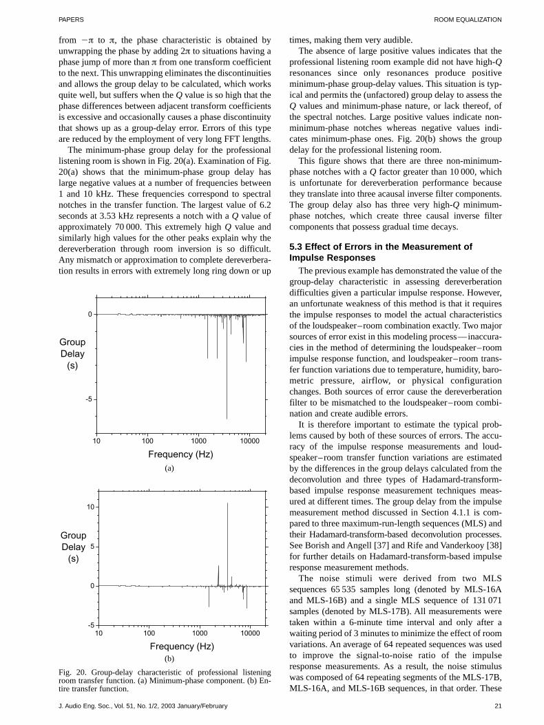
PAPERS ROOM EQUALIZATION
from π to π, the phase characteristic is obtained byunwrapping the phase by adding 2π to situations having aphase jump of more than π from one transform coefficientto the next. This unwrapping eliminates the discontinuitiesand allows the group delay to be calculated, which worksquite well, but suffers when the Q value is so high that thephase differences between adjacent transform coefficientsis excessive and occasionally causes a phase discontinuitythat shows up as a group-delay error. Errors of this typeare reduced by the employment of very long FFT lengths.
The minimum-phase group delay for the professionallistening room is shown in Fig. 20(a). Examination of Fig.20(a) shows that the minimum-phase group delay haslarge negative values at a number of frequencies between1 and 10 kHz. These frequencies correspond to spectralnotches in the transfer function. The largest value of 6.2seconds at 3.53 kHz represents a notch with a Q value ofapproximately 70 000. This extremely high Q value andsimilarly high values for the other peaks explain why thedereverberation through room inversion is so difficult.Any mismatch or approximation to complete dereverbera-tion results in errors with extremely long ring down or up
times, making them very audible.The absence of large positive values indicates that the
professional listening room example did not have high-Qresonances since only resonances produce positiveminimum-phase group-delay values. This situation is typ-ical and permits the (unfactored) group delay to assess theQ values and minimum-phase nature, or lack thereof, ofthe spectral notches. Large positive values indicate non-minimum-phase notches whereas negative values indi-cates minimum-phase ones. Fig. 20(b) shows the groupdelay for the professional listening room.
This figure shows that there are three non-minimum-phase notches with a Q factor greater than 10 000, whichis unfortunate for dereverberation performance becausethey translate into three acausal inverse filter components.The group delay also has three very high-Q minimum-phase notches, which create three causal inverse filtercomponents that possess gradual time decays.
5.3 Effect of Errors in the Measurement ofImpulse Responses
The previous example has demonstrated the value of thegroup-delay characteristic in assessing dereverberationdifficulties given a particular impulse response. However,an unfortunate weakness of this method is that it requiresthe impulse responses to model the actual characteristicsof the loudspeaker–room combination exactly. Two majorsources of error exist in this modeling process––inaccura-cies in the method of determining the loudspeaker–roomimpulse response function, and loudspeaker–room trans-fer function variations due to temperature, humidity, baro-metric pressure, airflow, or physical configurationchanges. Both sources of error cause the dereverberationfilter to be mismatched to the loudspeaker–room combi-nation and create audible errors.
It is therefore important to estimate the typical prob-lems caused by both of these sources of errors. The accu-racy of the impulse response measurements and loud-speaker–room transfer function variations are estimatedby the differences in the group delays calculated from thedeconvolution and three types of Hadamard-transform-based impulse response measurement techniques meas-ured at different times. The group delay from the impulsemeasurement method discussed in Section 4.1.1 is com-pared to three maximum-run-length sequences (MLS) andtheir Hadamard-transform-based deconvolution processes.See Borish and Angell [37] and Rife and Vanderkooy [38]for further details on Hadamard-transform-based impulseresponse measurement methods.
The noise stimuli were derived from two MLSsequences 65 535 samples long (denoted by MLS-16Aand MLS-16B) and a single MLS sequence of 131 071samples (denoted by MLS-17B). All measurements weretaken within a 6-minute time interval and only after awaiting period of 3 minutes to minimize the effect of roomvariations. An average of 64 repeated sequences was usedto improve the signal-to-noise ratio of the impulseresponse measurements. As a result, the noise stimuluswas composed of 64 repeating segments of the MLS-17B,MLS-16A, and MLS-16B sequences, in that order. These
J. Audio Eng. Soc., Vol. 51, No. 1/2, 2003 January/February 21
10 100 1000 10000
-5
0
GroupDelay
(s)
Frequency (Hz)(a)
Fig. 20. Group-delay characteristic of professional listeningroom transfer function. (a) Minimum-phase component. (b) En-tire transfer function.
10 100 1000 10000-5
0
5
10
GroupDelay
(s)
Frequency (Hz)(b)

FIELDER PAPERS
were reproduced at 80-dB SPL at the measurement posi-tion. As required, the Hadamard-transform-based methodswere matched to their appropriate sequences, while thedeconvolution method discussed in Section 4.1.1 was usedfor all three sequences. As discussed in Section 4.1.1, pre-emphasis and its complementary postemphasis were usedto reduce the effect of background noise.
The impulse responses were measured and truncated to10 560-sample length or 220 ms. Fig. 21 shows six exam-ples of the positive (non-minimum-phase) and the nega-tive (minimum-phase) group-delay values. The figures arethree-dimensional graphs where the X axis is frequency,the Z axis is time, and displacements along the Y axis rep-resent the six different impulse measurements. These aregrouped into three pairs, where each pair is associatedwith a particular noise sequence, either MLS-16A, MLS-16B, or MLS-17B. Within each pair there are two group-delay measurements arising from either the appropriateHadamard or the deconvolution method.
Examination of Fig. 21(a) shows a number of non-minimum-phase high-Q peaks, with notable ones locatednear dc and 2.53, 3.53, 4.24, 5.43, and 8.57 kHz. Theselocations are shown by solid lines on the XY plane. Ideallyeach measurement should have an identical group-delaycharacteristic, but unfortunately inspection shows thatsome of the group-delay peaks are only present in a few of
the measurements and the peak levels vary in amplitude.This variation among group-delay values means that allare likely to be inaccurate and that dereverberation basedon any of these impulse response measurements is likelyto create a mismatch to the actual loudspeaker–roomcombination, creating audible problems. The severity ofthe effect of the time-varying characteristics of the loud-speaker–room combination can be inferred by examina-tion of the deconvolution-derived group-delay values forall three MLS sequences. The three deconvolution-basedgroup-delay functions show a high degree of similarity,but there are substantial peak value variations near dc,2.53, and 3.53 kHz. Although not shown here, repeatedmeasurements of the same sequence show a similar levela group-delay variation.
Fig. 21(b) shows a similar relationship between theminimum-phase group-delay peaks (which are shown neardc and 1.5, 2.89, 3.07, 3.58, 4.01, 5.80, 7.20, 7.42, and8.57 kHz). As before, the peak levels show variations.There are also variations in the deconvolution-basedminimum-phase group delays near dc and 8.57 kHz. Inaddition, some group-delay curves identify a peak as min-imum phase in nature while others do not. A comparisonof Fig. 21(a) and (b) shows that this has occurred near dcand 8.57 kHz.
Despite the variations between different group-delay
22 J. Audio Eng. Soc., Vol. 51, No. 1/2, 2003 January/February
5
10
deconvolutionHadamard
deconvolutionHadamard
deconvolutionHadamard
MLS-17BMLS-16B
MLS-16A
900050000
Frequency (Hz)
Groupdelay
(s)
Fig. 21. Group-delay comparison for three noise sequences via two methods of measurement of impulse response for professional lis-tening room. (a) Non-minimum-phase. (b) Minimum-phase.
-5
-10
deconvolution
deconvolution
deconvolution
Hadamard
Hadamard
Hadamard
MLS-17BMLS-16B
MLS-16A
900050000
Frequency (Hz)
Groupdelay
(s)
(b)
(a)

PAPERS ROOM EQUALIZATION
determinations, their comparison indicates a certain con-sistency between measurements that reinforces the predic-tion of extreme difficulty in performing dereverberationsince there are a significant number of instances where allsix group delays produce these high-Q peaks. Unfort-unately the variation between group delays also meansthat even an ideal dereverberation process based on any ofthe impulse responses is likely to fail because of impulseresponse errors or varying loudspeaker–room characteris-tics. The fact that impulse response measurements containerrors is well known, as investigated by Vanderkooy [39],Nielsen [40], and Svensson and Nielsen [41], but the man-ifestation of these errors as group-delay inaccuracies hasnot been fully investigated.
5.4 Three Examples Assessed forDereverberation Feasibility
Although it has been shown that errors in impulseresponse measurements and the time-varying character ofloudspeaker–room characteristics create problems in thedereverberation of rooms, the group delay based on theimpulse response measurement found in Section 4.1.1 isvaluable in investigating whether the professional listen-ing room is an unusual and pathological example withrespect to the dereverberation process. Three additionalacoustic spaces are examined to answer this question.
The acoustic spaces are all larger in size than the pro-fessional listening room example. All spaces are utilizedfor the reproduction of movie soundtracks. One space is ahigh-quality cinema screening room, and the other two arecinemas of different sizes. Table 2 indicates the character-istics of each.
The impulse response of each example was measured ata central location, its length was truncated to be equal tothe reverberation time for 250–2500 Hz, and the groupdelay of each was computed. The results of these meas-urements are shown in Fig. 22.
Examination of this figure shows that the loud-
J. Audio Eng. Soc., Vol. 51, No. 1/2, 2003 January/February 23
Fig. 22. Group-delay characteristics of other acoustic spaces. (a) Cinema screening room. (b) Moderate-size cinema (cinema A).(c) Large cinema (cinema B).
(c)
10 100 1000 10000-25
-20
-15
-10
-5
0
5
10
15
20
25
GroupDelay
(s)
Frequency (Hz)
(a) (b)
Table 2. Characteristics of cinema acoustic spaces.
ReverberationVolume Time (ms) Number of
Room (m3) 0.25–2.5 kHz Seats
Screening room 800 270 80Cinema A 5400 500 650Cinema B 12 000 750 1500
10 100 1000 10000
-5
0
5
10
GroupDelay
(s)
Frequency (Hz)10 100 1000 10000
-5
0
5
10
GroupDelay
(s)
Frequency (Hz)

FIELDER PAPERS
speaker–room transfer functions also have a significantnumber of minimum-phase and non-minimum-phasenotches of extremely high-Q values. In fact, the examplesshow progressively higher Q-valued notches as the size ofthe rooms increases. Cinema B, with the largest dimen-sions and reverberation time, has the largest group-delayvalues. If twice the value given by Eq. (23) is used to esti-mate the Q value of the highest non-minimum-phase notchat 18 kHz, a value of over 1 million results. Although thisunusual value may be an artifact of the impulse measure-ment, the large numbers of peaks with values over 5 sec-onds indicate that dereverberation is even more problemat-ical than for the professional listening room.
6 CONCLUSION
This study has investigated the properties of traditionaland reverberation-reducing equalization methods. Equal-ization is studied using loudspeaker–room transfer func-tions derived from test signals recorded from omnidirec-tional microphones. Traditional equalization is drivenfrom the measurement of the steady-state spectral magni-tude, whereas reverberation-reducing equalization isdriven from measured impulse responses. Psychoacousti-cally derived criteria for spectral flatness and temporalresponse are developed to assess the audibility of equal-ization imperfections.
Traditional methods are effective in improving the timbrebalance in loudspeaker–room combinations but have sig-nificant limitations. The initially attractive reverberation-reducing equalization method is impractical due to itsextreme sensitivity to small errors in position and to meas-urement errors in impulse response determinations.
Traditional equalization methods typically employ one-third-octave or first- and second-order parametric filters tomatch the steady-state magnitude response of the loud-speaker–room transfer function to a target curve. The mag-nitude response is obtained by the appropriate fractional-octave spectrum analysis method and rms spatial averagingto obtain a compromise equalization over a specified lis-tening area. Traditional methods attempt to improve thespectral characteristics of the loudspeaker–room combina-tion without creating audible temporal artifacts. Becausethe temporal characteristics of the equalized loudspeaker–room combination are not significantly modified, this meansthat the traditional equalization methods discussed here arequite limited in their ability to provide very accurate timbrecorrection for signals with a time-varying character.
Reverberation-reducing equalization is evaluated byexamining the performance of complete dereverberationequalization, at a single microphone in space, for a mono-phonic setup in a professional listening room. This dere-verberation process involved the use of FFTs that are524 288 samples long to allow for very long equalizationfilters and used as its input much shorter 10 560-sample-length impulse responses that were zero padded to524 288 samples long. Equalization filters were centeredwithin the 524 288-sample interval to allow for substantialpre- and postringing. In addition, the ability to performdereverberation over a wider listening area was examined
by modeling acoustic cancellation reduction as a functionof displacement and examining the dereverberation resultswhen a 1.3-cm displacement of the microphone is made.
Errors in the dereverberation process manifested them-selves as extremely audible and annoying resonances.These arose from the presence of deep spectral notches inthe transfer functions of loudspeaker–room combinations,which created tonal artifacts that occurred long before andafter the direct-arrival sounds. Furthermore, an extremesensitivity to changes in position was found, which pre-vented the optimization of dereverberation over practi-cally sized listening areas. The quality of the dereverbera-tion was found to degrade even further for larger acousticspaces.
Despite the determination that the reverberation-reducing equalization methods considered here are notpractical to be used in real-world circumstances, a numberof useful tools were developed to assist in future work inthis area. The development of psychoacoustically derivedcriteria for spectral flatness, temporal masking, and tem-poral integration was found to be effective in predictingaudible problems. The characteristics of the group delaywere extremely useful in assessing dereverberation diffi-culties. Its use determined the proportion of minimum-phase and non-minimum-phase elements and therefore thedegree of causality possessed by the dereverberation filter.
The predicted long time-duration characteristics of theexcess-phase part of a loudspeaker–room combinationindicated that minimum-phase inversion would createpoor sound quality by smearing the time-domain responseof the equalized room.
7 REFERENCES
[1] C. P. Boner and C. R. Boner, “Minimizing Feedbackin Sound Systems and Room Ring Modes with PassiveNetworks,” J. Acoust. Soc. Am., vol. 37, pp. 131–135(1965 Jan.).
[2] T. Holman, “New Factors in Sound for Cinema andTelevision,” J. Audio Eng. Soc., vol. 39, pp. 529–539(1991 July/Aug.).
[3] R. B. Schulein, “In Situ Measurement andEqualization of Sound Reproduction Systems,” J. AudioEng. Soc., vol. 23, pp. 178–186 (1975 Apr.).
[4] H. Staffeldt and E. Rasmussen, “The SubjectivelyPerceived Frequency Response in Small and Medium-Sized Rooms,” SMPTE J., vol. 91, pp. 638–643 (1982July).
[5] A. V. Oppenheim, R. W. Schafer, and J. R. Buck,Discrete-Time Signal Processing (Prentice Hall, Engle-wood Cliffs, NJ, 1998), pp. 280–291, 571–588, 775–786.
[6] R. A. Greiner and M. Schoessow, “Design Aspectsof Graphic Equalizers,” J. Audio Eng. Soc., vol. 31, pp.394–407 (1983 June).
[7] D. A. Bohn, “Constant-Q Graphic Equalizers,” J.Audio Eng. Soc., vol. 34, pp. 611–626 (1986 Sept.).
[8] D. A. Bohn, “Operator Adjustable Equalizers: AnOverview,” presented at the AES 6th Int. Conf. on SoundReinforcement (1988 Apr.), paper 6-025.
[9] E. R. Geddes, “Small Room Acoustics in the Statis-
24 J. Audio Eng. Soc., Vol. 51, No. 1/2, 2003 January/February

PAPERS ROOM EQUALIZATION
tical Region,” in Proc. AES 15th Int. Conf. on Audio,Acoustics and Small Spaces (1998 Sept.), pp. 51–59.
[10] ANSI/SMPTE Std. 202M-1998, “For Motion-Pictures––Dubbing Theaters, Review Rooms and IndoorTheaters––B-Chain Electroacoustic Response,” Societyof Motion Picture and Television Engineers (1998).
[11] S. T. Neely and J. B. Allen, “Invertibility of aRoom Impulse Response,” J. Acoust. Soc. Am., vol. 66, pp.165–169 (1979 July).
[12] O. Kirkeby and P. A. Nelson, “Digital Filter Designfor Inversion Problems in Sound Reproduction,” J. AudioEng. Soc., vol. 47, pp. 583–595 (1999 July/Aug.).
[13] B. D. Radlovic and R. A. Kennedy, “Nonminimum-Phase Equalization and Its Subjective Importance inRoom Acoustics,” IEEE Trans. Sp. Audio Process., vol. 8,pp. 728–737 (2000 Nov.).
[14] P. A. Nelson, F. Orduna-Bustamante, and H.Hamada, “Inverse Filter Design and Equalization Zones inMultichannel Sound Reproduction,” IEEE Trans. Sp.Audio Process., vol. 31, pp. 185–192 (1995 May).
[15] O. Kirkeby, P. A. Nelson, H. Hamada, and F.Orduna-Bustamante, “Fast Deconvolution of Multichan-nel Systems Using Regularization,” IEEE Trans. Sp. AudioProcess., vol. 6, pp. 189–194 (1998 Mar.).
[16] L. G. Johansen and P. Rubak, “Listening TestResults from a New Digital Loudspeaker/Room Correc-tion System,” presented at the 110th Convention of theAudio Engineering Society, J. Audio Eng. Soc. (Abstracts),vol. 49, p. 529 (2001 June), preprint 5323.
[17] P. Rubak and L. G. Johansen, “Design and Eval-uation of Digital Filters Applied to Loudspeaker/ RoomEqualization,” presented at the 108th Convention of theAudio Engineering Society, J. Audio Eng. Soc. (Abstracts),vol. 48, p. 365 (2000 Apr.), preprint 5172.
[18] R. Genereux, “Signal Processing Considerationsfor Acoustic Environment Correction,” presented at theAES United Kingdom Conf. on Digital Signal Processing(1992 Aug.), paper DSP-14.
[19] O. Kirkeby, P. Rubak, and A. Farina, “Analysis ofIll-Conditioning of Multi-Channel Deconvolution Prob-lems,” in Proc. IEEE Workshop on Applications of SignalProcessing to Audio and Acoustics (1999 Oct.), pp.155–158.
[20] B. C. J. Moore, An Introduction to the Psychologyof Hearing, 4th ed. (Academic Press, New York, 1997),pp. 89–115, 128–133.
[21] L. D. Fielder, “Evaluation of the AudibleDistortion and Noise Produced by Digital Audio Convert-ers,” J. Audio Eng. Soc., vol. 35, pp. 517–535 (1987July/Aug.).
[22] F. E. Toole and S. E. Olive, “The Modification ofTimbre by Resonances: Perception and Measurement,” J.Audio Eng. Soc., vol. 36, pp. 122–142 (1988 Mar.).
[23] R. Bücklein, “The Audibility of Frequency Re-sponse Irregularities” (1962), reprinted in English in J.Audio Eng. Soc., vol. 29, pp. 126–131 (1981 Mar.).
[24] P. A. Fryer, “Intermodulation Distortion ListeningTests,” presented at the 50th Convention of the AudioEngineering Society, J. Audio Eng. Soc. (Abstracts), vol.23, p. 402 (1975 June), preprint B-5.
[25] B. C. J. Moore, B. R. Glasberg, C. J. Plack, and A.K. Biswas, “The Shape of the Ear’s Temporal Window,” J.Acoust. Soc. Am., vol. 83, pp. 1102–1116 (1988 Mar.).
[26] E. Zwicker and H. Fastl, Psychoacoustics: Factsand Models (Springer, Berlin, 1999), pp. 82–84.
[27] D. H. Raab, “Forward and Backward Maskingbetween Acoustic Clicks,” J. Acoust. Soc. Am., vol. 33, pp.137–139 (1961 Feb.).
[28] T. G. Dolan and A. M. Small, “Frequency Effectsin Backward Masking,” J. Acoust. Soc. Am., vol. 75, pp.932–936 (1984 Mar.).
[29] S. E. Olive and F. E. Toole, “The Detection ofReflections in Typical Rooms,” J. Audio Eng. Soc., vol.37, pp. 539–553 (1989 July/Aug.).
[30] W. Jesteadt, S. P. Bacon, and J. R. Lehman,“Forward Masking as a Function of Frequency, MaskerLevel, and Signal Delay,” J. Acoust. Soc. Am., vol. 71, pp.950–962 (1982 Apr.).
[31] D. Griesinger, “Beyond MLS––Occupied HallMeasurement with FFT Techniques,” presented at the101st Convention of the Audio Engineering Society, J.Audio Eng. Soc. (Abstracts), vol. 44, p. 1174 (1996 Dec.),preprint 4403.
[32] F. J. Harris, “On the Use of Windows for HarmonicAnalysis with the Discrete Fourier Transform,” Proc.IEEE, vol. 66, pp. 51–83 (1978 Jan.).
[33] B. D. Radlovic, R. C. Williamson, and R. A.Kennedy, “Equalization in an Acoustic Reverberant Envir-onment: Robustness Results,” IEEE Trans. Sp. Audio Pro-cess., vol. 8, pp. 311–319 (2000 May).
[34] M. Omura, M. Yada, H. Saruwatari, S. Kajita, K.Takeda, and F. Itakura, “Compensating of Room AcousticTransfer Functions Affected by Change of Room Temper-ature,” in Proc. IEEE Int. Conf. on Acoustics, Speech andSignal Processing (1999 May), paper 2030.
[35] L. G. Johansen and P. Rubak, “The Excess Phasein Loudspeaker/Room Transfer Functions: Can It Be Ig-nored in Equalization Tasks?,” presented at the 100thConvention of the Audio Engineering Society, J. AudioEng. Soc. (Abstracts), vol. 44, p. 636 (1996 July/Aug.),preprint 4181.
[36] A. B. Williams, Electronic Filter Design Handbook(McGraw-Hill, New York, 1981), pp. 7.1–7.4.
[37] J. Borish and J. B. Angell, “An Efficient Algorithmfor Measuring the Impulse Response Using Pseudoran-dom Noise,” J. Audio Eng. Soc., vol. 31, pp. 478–488(1983 July/Aug.).
[38] D. D. Rife and J. Vanderkooy, “Transfer-FunctionMeasurement with Maximum-Length Sequences,” J.Audio Eng. Soc., vol. 37, pp. 419–444 (1989 June).
[39] J. Vanderkooy, “Aspects of MLS Measuring Sys-tems,” J. Audio Eng. Soc., vol. 42, pp. 219–231 (1994 Apr.).
[40] J. L. Nielsen, “Maximum-Length Sequence Mea-surement of Room Impulse Responses with High-LevelDisturbances,” presented at the 100th Convention of theAudio Engineering Society, J. Audio Eng. Soc. (Abstracts),vol. 44, p. 650 (1996 July/Aug.), preprint 4267.
[41] U. P. Svensson and J. L. Nielsen, “Errors in MLSMeasurements Caused by Time Variance in Acoustic Sys-tems,” J. Audio Eng. Soc., vol. 47, pp. 907–927 (1999 Nov.).
J. Audio Eng. Soc., Vol. 51, No. 1/2, 2003 January/February 25

FIELDER PAPERS
26 J. Audio Eng. Soc., Vol. 51, No. 1/2, 2003 January/February
THE AUTHOR
Louis Fielder received a B.S. degree in electrical engi-neering from the California Institute of Technology in1974 and an M.S. degree in acoustics from the Universityof California, in Los Angeles, in 1976. From 1976 to 1978he worked on electronic component design for customsound reinforcement systems at Paul Veneklasen andAssociates. From 1978 to 1984 he was involved in digitalaudio and magnetic recording research at AmpexCorporation. At that time he became interested in apply-ing psychoacoustics to the design and analysis of digitalaudio conversion systems. Since 1984 he has worked at
Dolby Laboratories and has been involved in the applica-tion of psychoacoustics of the development of audio sys-tems. He has written a number of papers on the determi-nation of the limits of performance for digital audio andlow-frequency loudspeaker systems. He has also workedon the development of low bit-rate audio coders for musicdistribution, transmission, and storage applications from1984. Currently he is working in the area of roomacoustics for small- to medium-sized rooms.
Mr. Fielder is a fellow and a past president of the AudioEngineering Society.

PAPERS
0 INTRODUCTION
In the context of signal processing, rational orthonor-mal filter structures were first introduced in the 1950s byKautz, Huggins, and Young [1]–[3]. Kautz showed that anorthogonalization process applied to a set of continuous-time exponential components produces orthonormal basisfunctions having particular frequency-domain expressions.Much earlier Wiener and Lee [4] proposed synthesis net-works based on some classical orthonormal polynomialexpansions [5]. The idea of representing functions in ortho-normal components is elementary in Fourier analysis, butthe essential observation in the aforementioned cases wasthat some time-domain basis functions have rationalLaplace transforms with a recurrent structure, defining anefficient transversal synthesis filter.
Discrete-time rational orthonormal filter structures can beattributed to Broome [6] as well as the baptizing of the dis-crete Kautz functions, consequently defining the discrete-time Kautz filter. The point of reference in the mathemati-cal literature is somewhat arbitrary, but reasonable choicesare the deductions made in the 1920s to prove intercon-nections between rational approximations and interpola-tions, and the least-square (LS) problem, which wereassembled and further developed by Walsh [7].
Over the last ten years there has been a renewed inter-
est toward rational orthonormal model structures, mainlyfrom the system identification point of view [8]–[11]. Theperspective has usually been to form generalizations to thewell-established Laguerre models in system identification[12]–[14] and control [15]. In this context the Kautz filteror model has often the meaning of a two-pole generaliza-tion of the Laguerre structure [9], whereupon further gen-eralizations restrict as well to structures with identicalblocks [16]. Another, and almost unrecognized, connectionto recently active topics in signal processing are the ortho-normal state-space models for adaptive IIR filtering [17],with some existing implications to Kautz filters [18], [19].
Kautz filters have found very little use in audio signalprocessing, to cite rarities [20]–[24]. One of the reasons iscertainly that the field is dominated by the system identifi-cation perspective. The more inherent reason is that there isan independent but related tradition of frequency-warpedstructures, which is already well grounded and sufficientfor many tasks in audio signal processing. Frequencywarping provides a (rough) approximation of the constant-Q resolution of modeling [25] as well as a good matchwith the Bark scale, which is used to describe the psy-choacoustical frequency scale of human hearing [26]. Fora recent overview of frequency warping, see [27].
In our opinion there is a certain void in generality, bothin the proposed utilizations of Kautz filters as well as inthe warping-based view of the frequency resolution ofmodeling. There are some implications [28], [29] thatKautz filters would also be well applicable to adaptivemodeling of audio systems, such as acoustic echo cancel-
J. Audio Eng. Soc., Vol. 51, No. 1/2, 2003 January/February 27
Kautz Filters and Generalized Frequency Resolution:Theory and Audio Applications*
TUOMAS PAATERO AND MATTI KARJALAINEN, AES Fellow
Helsinki University of Technology, Laboratory of Acoustics and Audio Signal Processing, Espoo, Finland
Frequency-warped filters have recently been applied successfully to a number of audioapplications. The idea of all-pass delay elements replacing unit delays in digital filters allowsfor focusing enhanced frequency resolution on the lowest (or highest) frequencies andenables a good match to the psychoacoustical Bark scale. Kautz filters can be seen as afurther generalization, where each all-pass element may be different, allowing also complex-conjugate poles. This enables an arbitrary allocation of frequency resolution to filter design,such as modeling and equalization (inverse modeling) of linear systems. Strategies for usingKautz filters in audio applications are formulated. Case studies of loudspeaker equalization,room response modeling, and guitar body modeling for sound synthesis are presented.
* An early version of this paper was presented in the 110thConvention of the Audio Engineering Society, Amsterdam, TheNetherlands, 2001 May 12–15; revised 2002 April 18.

PAATERO AND KARJALAINEN PAPERS
lation and channel equalization. In this paper we demon-strate the use of Kautz filters in pure filter synthesis, thatis, modeling of a given target response, which was actu-ally their original usage. Quite surprisingly, to our knowl-edge there have not actually been any proposals in thisdirection on the level of modern computational means indesign and implementation.
The objective of this paper is to introduce the conceptof Kautz filters in a practical manner and from the point ofview of audio signal processing. After a brief theoreticalpart we present various methods for the most essentialingredient in Kautz filter design, namely, choosing a par-ticular structure. Audio applications of Kautz filtering,including loudspeaker equalization, room response model-ing, and modeling of an acoustic guitar body, are demon-strated and compared with more traditional approaches.
1 KAUTZ FILTER STRUCTURES
For a given set of desired poles zi in the unit disk, thecorresponding set of rational orthonormal functions isuniquely defined in the sense that the lowest order rationalfunctions Gi(z), square-integrable and orthonormal on theunit circle, analytic for z > 1, are of the form [7]
, , ,G zz z
z z
z z
z zi
1
10 1
*
* *
i
i
i i
j
j
j
i
1 1
1
0
f%^ h (1)
where z* denotes the complex conjugate of z. The mean-ing of orthonormality is most economically established inthe time domain: for the impulse responses gi(n) of Eq.(1), the time-domain inner products satisfy
!,
,
, .g g g n g n
i k
i k
0
1
*
i k i kn 0
3
!_ ^ ^i h h * (2)
For the remaining conditions of square integrability andanalyticity it is sufficient to presume stability and causal-ity of the rational transfer function, that is, that z i < 1 forall the poles.
Eq. (1) forms clearly a repetitive structure: up to a givenorder, that is, the number of poles, functions associatedwith the subsets zj
ij0 of an ordered pole set zj
Nj0 are
produced as intermediate substructures defining a tappedtransversal system. In agreement with the continuous-timecounterpart, a weighted sum of these functions is called aKautz filter and depicted in Fig. 1.
Defined in this manner, Kautz filters are merely a classof fixed-pole IIR filters, forced to produce orthonormaltap-output impulse responses.1 A particular Kautz filter isthus determined by a pole set, consequently defining thefilter order, the all-pass filter backbone, as well as the cor-responding tap-output filters. The Kautz filter response isthus defined by the linear-in-parameters wi formulas
andH z w G z h n w g n i ii
N
i ii
N
0 0
! !^ ^ ^ ^h h h h (3)
which despite their appearance as parallel systems are trans-versal in nature because of the particular form of Eq. (1).
A gentle approach to understanding Kautz filters from atraditional digital filtering point of view is to start from anFIR filter and replace the unit delays by first-order all-passsections, that is, by frequency-dependent delays. If thesections are equal, the resulting structure is a warped FIRfilter (WFIR) [27]. With an additional cascaded normaliza-tion term the structure is a Laguerre filter (normalizedwarped filter). Finally, when the all-pass sections have indi-vidual pole values, possibly complex ones, the result is aKautz filter, a generalized transversal filter. In analogy tothe FIR filter, Eq. (3) can be seen as a truncated generalizedz transform or as a generalization of the unit-delay decom-positions of a given system. Note that due to internal feed-backs it is a filter with an infinite impulse response.
Fig. 2 illustrates time- and frequency-domain responsesof an example Kautz filter with a real pole set 0.1 0.2 0.30.4 0.5 0.6 0.7 0.8 0.9. In the time domain the tap outputshave excessively increasing delays, similar to FIR filtertaps but with infinitely long responses. In the frequencydomain each tap has a magnitude response that is inde-pendent of the tap position, in this sense resembling a par-allel filter bank.
1.1 Kautz Modeling of Signals and SystemsDefined by any set of points zi
∞i0 in the unit disk, Eq.
(1) forms an orthonormal set that is complete, or a base,with a moderate restriction on the poles zi [7]. The cor-responding time-domain basis functions gi(n)∞i0 areimpulse responses or inverse z transforms of Eq. (1). Thisimplies that a basis representation of any causal and finite-
28 J. Audio Eng. Soc., Vol. 51, No. 1/2, 2003 January/February
1Kautz filters are clearly related to other orthogonal filter for-mulations, but here we just exploit this connection by referringto favorable numerical properties implied by the orthonormality[30]–[33].
Fig. 1. Kautz filter. For zi 0 in Eq. (1) it degenerates to an FIR filter and for zi a, 1 < a < 1, it is a Laguerre filter, where tap fil-ters are replaced by a common prefilter.

PAPERS KAUTZ FILTERS AND FREQUENCY RESOLUTION
energy discrete-time signal is obtained as its generalizedFourier series, that is, as infinite sums of the form of Eqs.(3) with corresponding Fourier coefficients wi (h, gi) (H, Gi) with respect to the time- or frequency-domain ortho-normal basis functions and definitions for the inner products.The bounded-input–bounded-output (BIBO) stability condi-tion for a causal system implies square summability,
n nnn
2
00
33
< < h h&3 3!! ^ ^h h (4)
that is, impulse responses of causal and stable (CS) lineartime-invariant (LTI) systems form a subset of finite energysignals, which makes Eqs. (3) valid model structures forinput-output data identification.
Kautz filters provide models for many types of systemidentification and approximation schemes, includingadaptive filtering, for both fixed and nonfixed pole struc-tures. Also in the Kautz model case there are various inter-pretations, criteria, and methods for the parameterizationof the model. Here we address only the “prototype” LSapproach implied by the signal space description: tap-output signals of a Kautz filter xi(n) Gi[x(n)] to inputx(n) span a finite-dimensional approximation space, pro-viding an LS optimal approximation to any CSLTI systemwith respect to the basis. The parameterization, that is, thefilter weights are solutions of the normal equations assem-bled from correlation terms of the tap outputs and thedesired output y(n). For example, in matrix form, definingthe correlation matrix R, [r]i j (xi, xj), the weight vectorw is the solution of the matrix equation
, ,p y xRw p i i_ i7 A (5)
where p is the correlation vector.2 This simply utilizes thepreviously defined time-domain inner product Eq. (2) ofthe signals, so there are also definitions for the frequency-domain correlation terms, and separately for deterministicand stochastic signal descriptions, but this notion is just
included to indicate similarities with the FIR modelingcase.
Actually we further limit our attention to the approxi-mation of a given target response since the input–outputsystem identification framework is a bit pompous andimpractical for most audio signal processing tasks.Although typical operations such as inverse modeling andequalization are basically identification schemes, they areusually convertible to the approximation problem.Furthermore we are not going to address here the interest-ing question of the invertibility of a Kautz filter, whichwould require elimination of delay-free loops, or an imple-mentation method proposed in [34].
For a given system h(n) or H(z), Fourier coefficientsprovide LS optimal parameterizations for the correspon-ding Kautz model, or synthesis filter, with respect to thepole set. Evaluation of the Fourier coefficients
, ,c h g H G i i i_ _i i (6)
can be implemented by feeding the time-reversed signalh(n) to the Kautz filter and reading the tap outputs xi attime n 0 ,
, .c x x n h n g n0 i i i i*^ ^ ^ ^h h h h (7)
This implements inner products by filtering (convolution[*]), and it can be seen as a generalization of the FIRdesign by truncation. It should be noted that here the LScriterion is applied on the infinite time horizon and not, forexample, in the time window defined by h(n). We use thesetrue orthonormal expansion coefficients because they areeasy to obtain, providing implicitly simultaneous time- andfrequency-domain design and powerful means to the Kautzfilter structure (that is, pole position) optimization. More-
J. Audio Eng. Soc., Vol. 51, No. 1/2, 2003 January/February 29
2The term correlation is used to point out that this is a genuinegeneralization of the Wiener filter setup.
Fig. 2. (a) Time-domain Kautz functions (tap outputs of Kautz filter backbone) gi(n), i 0, … , 8, for real-valued Kautz poles 0.1 0.20.3 0.4 0.5 0.6 0.7 0.8 0.9. Repetitive offset of 0.5 applied for improved readability. Compare gi(n) with shifted impulses in an FIRfilter. (b) Frequency-domain Kautz magnitude functions 20 logGi(ω) for same case.
(a) (b)0 5 10 15 20 25 30 n/samples
-4
-3
-2
-1
0
1
g0(n)
g1(n)
g2(n)
g3(n)
g4(n)
g5(n)
g6(n)
g7(n)
g8(n)
0 0.1 0.2 0.3 0.4 0.5-15
-10
-5
0
5
10
dB
G0(²)
G8(²)
Normalized frequency f/fs

PAATERO AND KARJALAINEN PAPERS
over, the coefficients are independent of ordering andapproximation order,3 which makes choosing poles, approx-imation error evaluation, and model reduction efficient.
1.2 Real-Valued Kautz Functions for Complex-Conjugate Poles
A Kautz filter produces real tap-out signals only in thecase of real poles. In principle this does not in any waylimit its potential capabilities of approximation a real sig-nal or system. However, we may want the processing, thatis, signals internal to a filter, coefficients, and arithmeticoperations to be real-valued. A restriction to real linear-in-parameter models can also be seen as a categoric step inthe optimization of the structure.4
From a sequence of real or complex-conjugate poles it isalways possible to form real orthonormal structures.Symbolically this is done by applying a block diagonal uni-tary transformation to the outputs, consisting of 1’s corre-sponding to real poles and 2 2 rotation elements corre-sponding to pole pairs. From the infinite variety of unitarilyequivalent possible solutions5 it is sufficient to use the intu-itively simple structure of Fig. 3, proposed by Broome [6].
The second-order section outputs of the backbone struc-ture in Fig. 3 are already orthogonal, from which tap-output pairs are produced as orthogonal components ofdifference and sum, x(n) x(n 1) and x(n) x(n 1),respectively. The orthonormalizing terms are then
andp z q z1 1 i i1 1
` `j j (8)
and they are determined by the corresponding pole pairz i, z*
i so that
/
/
ρ ρ γ
ρ ρ γ
γ
ρ
Re
p
q
z
z
1 1 2
1 1 2
2
i i i i
i i i i
i i
i i2
_ _
_ _
i i
i i
# -
(9)
where γi and ρi can be recognized as corresponding second-order polynomial coefficients. The construction worksalso for real poles, producing a tap-output pair correspon-ding to a real double pole, but we use a mixture of first-
and second-order sections in the case of both real andcomplex-conjugate poles.
A Kautz filter example with complex-conjugate pole pairsis characterized by frequency-domain responses in Fig. 4(b)and (c). Notice the complementary orthogonal behavior ofresonances for odd versus even tap outputs. Kautz pole posi-tions in the z plane are shown by circles in Fig. 4(a).
2 METHODS FOR POLE DETERMINATION
Contrary to all-pole or all-zero modeling and filterdesign there are in general no analytical methods to solvefor optimal pole–zero filter coefficients. Kautz filterdesign can be seen as a two-step procedure, involving thechoosing of a particular Kautz filter pole set and the eval-uation of the corresponding filter weights. The fact thatthe latter task is much easier, better defined, and inher-ently LS optimal makes it tempting to use sophisticatedguesses and random or iterative search in the pole opti-mization. For a more analytic approach, the whole idea inthe Kautz concept is how to incorporate desired a prioriinformation to the Kautz filter. This may mean knowledgeon system poles or resonant frequencies and the corre-sponding time constants, or indirect means, such as anyall-pole or pole–zero modeling method to find potentialKautz filter poles.
A practical way to limit the degrees of “freedom” in fil-ter design is to restrict to structures with identical blocks,
30 J. Audio Eng. Soc., Vol. 51, No. 1/2, 2003 January/February
3According to Eq. (5), coefficients ci depend only on the cor-responding basis function. This means that for a fixed (ordered)base gi
∞i0 we obtain the same coefficients for any chosen
approximation order. Moreover, the energy of the approximationis distributed orthogonally in the coefficients, which makes theapproximation error E (h, h) ΣN
i0 ci 2, independent of the
ordering of the basis functions. For various permutations of afixed basis function set, gi
Ni0 the tap-output magnitude
responses are indeed independent of ordering, but the phaseresponses differ. However, the phase response of the approxima-tion h(n) ΣN
i0 cigi(n) is independent of ordering.4Assuming that we are approximating a real-valued response,
we know that the “true” poles of the system are real or occur incomplex-conjugate pairs, which makes all other choices suboptimal.
5Some of the Kautz filter deductions are made directly on thereal function assumption [6]. Moreover, the state-space approachto orthonormal structures with identical blocks, the generalizedorthonormal basis functions of Heuberger, is based on balancedrealizations of real rational all-pass functions [8].
Fig. 3. One realization for producing real Kautz filter tap-output responses defined by a sequence of complex-conjugate pole pairs.Transversal all-pass backbone of Fig. 1 is restored by moving denominator terms one step to the right and compensating for change intap-output filters.

PAPERS KAUTZ FILTERS AND FREQUENCY RESOLUTION
that is, to use the same smaller set of poles repeatedly. Thepole optimization and the model order selection problemsare then essentially separated, and various optimizationmethods can be applied to the substructure. In addition,for the structure of identical blocks, a relation betweenoptimal model parameters and error energy surface sta-tionary points with respect to the poles may be utilized[35] as well as a classification of systems to associate sys-tems and basis functions [36]. However, in the followingwe mainly focus on practical methods for choosing a dis-tributed pole set.
2.1 Generalized Descriptions of FrequencyResolution
As mentioned earlier, frequency-warped configurationsin audio signal processing [27] constitute a self-contained
tradition originating from warping effects observed inanalog-to-digital mappings and digital filter transforma-tions [37]. The concept of a warped signal was introducedto compute nonuniform resolution Fourier transforms usingthe fast Fourier transform (FFT) [25] and in a slightly dif-ferent form to compute warped autocorrelation terms forwarped linear predictions [38]. The original idea of replac-ing a unit delay element with a first-order all-pass opera-tor in a transfer function, that is,
λ
λz
z
z
1
1
1
1
! (10)
was restated and applied to general linear filter structures[39]–[41].
The warping effect or resolution description introducedby first-order all-pass warping is defined by the all-pass
J. Audio Eng. Soc., Vol. 51, No. 1/2, 2003 January/February 31
-1 -0.5 0 0.5 1
-1
-0.5
0
0.5
1
Real part
Imag
inar
y pa
rt
(a)
Fig. 4. Example of real-valued Kautz filter for complex-conjugate pole pairs. (a) Poles (only one per pair shown) positioned logarith-mically in frequency ( pole angle) with pole radius of 0.97. (b) Magnitude responses for odd tap outputs. (c) Magnitude responsesfor even tap outputs. (See Fig. 3.)
(c)
0.05 0.1 0.15 0.2 0.25 0.3 0.35 0.4 0.45 0.5-30
-20
-10
0
10
20( ) g p p p
Normalized frequency f/fs
Mag
nitu
de /
dB
(b)
0.05 0.1 0.15 0.2 0.25 0.3 0.35 0.4 0.45 0.5-30
-20
-10
0
10
20
Normalized frequency f/fs
Mag
nitu
de /
dB

PAATERO AND KARJALAINEN PAPERS
phase function of Eq. (10). The warping parameter λ canbe chosen to approximate desired frequency-scale map-pings, such as the perceptually motivated Bark scale, withrespect to different error criteria and sampling rates [26].This is complete in the sense that the first-order all-passelement is the only (rational, stable, and causal) filter hav-ing a one-to-one phase function mapping. Parallel struc-tures can be constructed to approximate any kind of warp-ing [42], including the logarithmic scale [43], but the aimof this chapter is to broaden the concept of frequency res-olution to account for the resolution allocation introducedby a Kautz filter.
There is a certain deep-rooted conceptual difficulty inplacing Kautz filter techniques in the general frameworkof LTI filtering and its warped counterparts. Warped filtersprovide an efficient way to incorporate a desired fre-quency resolution in traditional FIR and IIR filter design,if the bilinear mapping in Eq. (10) is considered sufficientand flexible enough. However, a more fine-structured orcase-specific frequency resolution allocation would oftenbe preferable. On the other hand, it can be theoreticallyproven that FIR filters are the optimal choice if (exponen-tial) stability is the only thing that is known of the systemto be modeled. Actually the opposite of this statement isused in motivation of the Kautz model for approximatingresonant systems [36]. Furthermore, in our cases of typicalaudio-related responses it can be readily shown that theKautz filter techniques proposed in Section 2.3 usuallyprovide in the LS sense the best IIR filter designs, whichmay seem surprising regarding the vast number of methodsavailable. Warped counterparts of FIR and IIR filters mightbe the optimal choices in producing a desired simple globalallocation of frequency resolution, but for a specific filterdesign problem this is probably not the case. Combiningthese arguments, our hypothesis is that if a target responsehas clearly distinguishable resonant features, it is alwayspossible to design a Kautz filter with at least the same tech-nical and perceptual quality, but with better efficiency.
The Laguerre filter differs structurally from the warpedFIR filter only in the orthonormalizing all-pole prefilter,
, , ,λ
λ
λ
λH z
zw
z
zi
1
1
10 1
i
i
N i
1
2
01
1
f!J
L
KK^
N
P
OOh
(11)
that is, the term before the weighted tap summation (seealso Fig. 1). The effect of this distinction can be seen as amere technicality, which can be compensated if needed, oreven as a favorable frequency emphasis in the modeling[38]. Actually we have already referred to three variationsof warping, the Laguerre and the all-pass warping and theOppenheim et al. construction [25], which is a biorthogo-nal analysis–synthesis structure. In practice the questionwhich warping to choose may not be of importance, butsignal and system transformations defined by the Laguerreanalysis–synthesis structure are the only truly orthonor-mal transform pairs related to mapping (10).
The orthonormal Laguerre transformation of signalsand systems has a generalization to Kautz structures withidentical blocks defined by any rational all-pass transfor-
mation [44], [10], so actually it is just a question of howto interpret the well-defined phase characteristics as a fre-quency resolution mapping. The same applies to the gen-eral Kautz model. The phase function of the transversalall-pass backbone is completely determined by the poleset (as a whole) and we should “just” find a way to decodethis information as a generalized frequency resolutionallocation. Audio application cases presented in Section 3help with understanding intuitively how to focus resolu-tion on the frequency axis in a desirable way.
Fig. 5 also characterizes this from a couple of view-points for the same case of complex-conjugate poles withlogarithmically distributed pole angles and constant poleradius, as was used in Fig. 4. Fig. 5(b) shows the phasefunctions for each individual pole-pair section and Fig.5(c) plots the accumulated phases at the tap outputs of theall-pass sections (from high-frequency to low-frequencypole angles). Fig. 5(d) is the group delay τg dφ/dω ofthe all-pass backbone. The accumulated phase in Fig. 5(c)is equivalent to the effect of frequency warping in theLaguerre case, although the concept of warping is not asclear and should be used with caution. Similarly, the groupdelay can be interpreted as a measure of frequency resolu-tion. It illustrates well how the resolution in this case is high-est at low frequencies and then decreases, except locally atfrequencies corresponding to the resonating pole pairs.
A trivial way to attain a desired frequency resolutionallocation in Kautz modeling is to use suitable pole distri-butions. We may place (complex-conjugate) poles withpole angle spacings corresponding to any frequency reso-lution mapping. The choosing of pole radii is also to betaken into account so that we can use more sophisticatedchoices than a constant radius. Motivated from our exper-iments on producing warping on a logarithmic scale withparallel all-pass (and generalized parallel orthonormal)structures [43] we have, for example, used pole radiiinversely proportional to the pole angles.
2.2 Manual Fitting to a Given ResponseIt is always possible to simply adjust the Kautz filter
poles manually through trial and error in order to producea Kautz filter matching well with a given target response.A Kautz filter impulse response is a weighted superposi-tion of damped sinusoids which provide for direct tuningof a set of resonant frequencies and the correspondingdecay time constants. In principle this allows for veryflexible time-domain design, especially if some otherweighting than the LS parameterization is chosen.
By direct inspection of the time and frequency responsesit is relatively easy to find useful pole sets by selecting a setof prominent resonances and proper pole radius tuning.Choosing the complex-conjugate pole angles is more crit-ical than the pole radius selection in the sense that the fil-ter coefficients perform automatic weighting of the sinu-soidal components. In practice, however, when designinglow-order models for highly resonant systems, poles mustbe fine-tuned very close to the unit circle.
An obvious way to improve the overall modeling with astructure based on a fixed set of resonances is to use thecorresponding generating substructure repetitively, produc-
32 J. Audio Eng. Soc., Vol. 51, No. 1/2, 2003 January/February

PAPERS KAUTZ FILTERS AND FREQUENCY RESOLUTION
ing a Kautz filter with identical blocks. There is no obliga-tion to use the same multiplicity for all poles, but it makesmodel reduction easier. If a set of poles is determined for asubstructure that is used repetitively, some kind of damp-ing by reduced pole radii would be advisable.
2.3 Methods Implied by OrthogonalityWe have chosen our model to a given target response
h(n) to be the truncated series expansion
, ,h n c g n c h g i i i ii
N
0
!t^ ^ _h h i (12)
which makes approximation error evaluation and controleasy. For any (orthonormal) gi and approximation orderN, the approximation error energy satisfies
E c H c i ii
N
i N
2 2
01
3
!! (13)
where H (h, h) is the energy of h(n). Hence we get theenergy of an infinite-duration error signal as a by-productfrom finite filtering operations, previously described forthe evaluation of the filter weights.
As a more profound consequence of the orthogonality,the all-pass operator defined by the (transversal part ofthe) chosen Kautz filter induces a complementary divisionof the energy of the signal h(n), n 0, … , M [3]. Anall-pass filter A(z) is lossless by definition, and (from thepreceding) it can be deduced that the portion of theresponse a(n) A[h(n)] in the time interval [M, 0]corresponds to the approximation error E, that is, the
Kautz filter optimization problem reduces to the mini-mization of the energy of a finite-duration signal.
We have encountered three attempts to utilize the con-cept of complementary signals in the pole position opti-mization, at least implicitly [45]–[47]. McDonough andHuggins replace the all-pass numerator with a polynomialapproximating the denominator mirror polynomial to pro-duce linear equations for the polynomial coefficients in aniteration scheme [45]. Friedman has constructed a networkstructure for parallel calculations of all partial derivativesof the approximation error with respect to the real second-order polynomial coefficient associated to the complexpole pairs, to be used in a gradient algorithm [46].6
Brandenstein and Unbehauen have proposed an iterativemethod resembling the Steiglitz–McBride method of pole –zero modeling to pure FIR-to-IIR filter conversion [47],which we have adapted to the context of Kautz filter opti-mization. We have implemented and experimented with allthe aforementioned algorithms, but in general just themethod of Brandenstein and Unbehauen (BU method) isfound reliable. It genuinely optimizes in the LS sense thepole positions of a real Kautz filter, producing uncondition-ally stable and (theoretically globally) optimal pole sets fora desired filter order. Furthermore the BU method works onrelatively high filter orders, for example, providing sets of300 distributed and accurate poles, which would beunachievable with standard pole–zero modeling methods.
J. Audio Eng. Soc., Vol. 51, No. 1/2, 2003 January/February 33
6An iterative solution based on a modified error criterion ispresented in [48] as well as a connection to the generalizedSteiglitz–McBride method in adaptive IIR filtering in [17].
Fig. 5. Phase and resolution behavior of complex-conjugate pole Kautz filter characterized in Fig. 4. (a) Pole positions. (b) Phase func-tions of individual all-pass sections. (c) Accumulated phase in all-pass tap outputs. (d) Group delay (phase derivative).
(c) (d)
0 1 2 30
50
100
angle / rad
phas
e / r
ad
1 0 1
1
0.5
0
0.5
1
Real part
Imag
inar
y pa
rt
(a)
0 1 2 3
103
102
angle / rad
0 1 2 30
2
4
6
angle / rad
phas
e / r
ad
(b)

PAATERO AND KARJALAINEN PAPERS
An outline of our Kautz filter pole-generation method,modified from Brandenstein and Unbehauen [47] follows.
• The algorithm is based on approximating an all-passoperator A(z) of a given order N with
A zD z
z D z( )
( )
( )k
k
N k
1
1
t
^^
`
hh
j(14)
where 1, D(1)(z), D(2)(z), … are iteratively generatedpolynomials, restricted to the form
,D z d z D z1 1 ( ) ( )kik i k
i
N
11
!^ ^h h
, , . ( )k 1 2 15 f
• Eq. (14) converges to an all-pass function if D(k)(z) D(k1)(z) → 0.
• The objective is to minimize the output of Eq. (14) tothe input X(z) zL H(z1) [the z transform of h(n)].Denote U(k)(z) A(k)[X(z)].
• Define Y(k)(z) X(z)/D(k1)(z) [all-pole filtered h(n)].• Now U(k)(z) zN D(k)(z1)Y(k)(z), and by substituting
Eq. (15) and rearranging,
.Y z z D z U z z Y z ( ) ( ) ( ) ( ) ( )k N k k N k11
1 ^ ` ^ ^h j h h
(16)
• Collecting common polynomial terms into a matrixequation produces A(k) d(k) u(k) b(k), where d(k) andu(k) are unknown. The solution of A(k) d(k) b(k) mini-mizes the square norm of u(k) A(k) d(k) b(k).
• The BU algorithm proceeds as follows:Step 1: For k 1, 2, … , filter h(n) by 1/D(k1)(z) toproduce the elements of A(k) and b(k).Step 2: Solve A(k) d(k) b(k), d(k) A(k) \b(k), the (mir-ror) polynomial coefficients of D1
(k)(z). Go to step 1.Step 3: From a sufficient number of iterations, chooseD(k)(z) that minimizes the true LS error. The Kautz fil-ter poles are the roots of D(k)(z).
2.4 Hybrid MethodsBy trying to categorize various methods for choosing a
particular Kautz filter we do not in any way intend to becomplete or exclusive. There are certainly many other pos-sibilities as well as modifications and mixtures of the onespresented. For example, we have not addressed pole posi-tion optimization methods based on input–output descrip-tions of the system, which could in some cases be usefuleven if the target response is available.
An obvious way to modify the optimization is to manip-ulate the target response. Time-domain windowing orfrequency-domain weighting by suitable filtering may beapplied, or alternatively, the optimization can be parti-tioned using selective filters. For example, the BU methodis based on solving at every iteration a matrix equationwith the dimensions implied by the duration of the targetresponse and the chosen model order, and therefore patho-logical behavior can be decreased by truncation. By divid-
ing the frequency range into two (or more) parts, separatemethods and allocation of the modeling resolution on thesubbands can be applied.
In the case where a substructure is assigned and used ina Kautz filter with identical blocks there is always thequestion of compensating for the repetitive appearance ofthe poles. We have used constant pole radius damping,individual tuning of the pole radii, and an ad hoc methodwhere we simply raise the pole radius to the power of thenumber of blocks used in the Kautz filter. For poles withdissimilar radii this approach is certainly better justifiedthan using constant damping.
The most efficient strategy, in our experience, is tocombine various methods with the BU method. At theleast this may mean examining the produced pole set andpossibly omitting some of the poles. For a sharply reso-nant system, poles very close to the unit circle areobtained, and although the BU method produces (at leasttheoretically) unconditionally stable poles, the resultingpole set should be checked for numerical oddities. Theremay also appear weak poles that make practically no con-tribution to the model. Furthermore one does not usuallycare for real poles because by definition they are eitherweak or products of the anomalies in the target response atfrequency band edges. In addition sometimes a cluster ofpoles may be represented by a single conjugate pole pair.
A more systematic pruning of the BU pole set may alsobe performed, for example, by simply omitting the polesoutside a specific frequency (pole angle) region, or byspacing out the pole set according to some rule. The factthat a high-order distributed BU pole set is a good repre-sentation of the whole resonance structure can be used toassociate poles directly with different choices of promi-nent resonances. Typically a sharp resonance is repre-sented by a single pole pair, with pole angles correspon-ding (almost) exactly to the peak frequency, andappropriately tuned pole radii. Because of the latter, thishas also proven to be a useful approach in selecting a sub-structure for the Kautz filter with identical blocks. As aninverse to the pruning, one may also add and manually orby rule tune poles to the BU pole set. This is demonstratedin the loudspeaker case study that follows.
We have also developed and applied successfully acombination of frequency warping and the BU method.By using the warped target response in the BU method wemay optimize the pole positions corresponding to Kautzmodeling on a warped frequency scale. The poles in theoriginal domain are obtained simply by mapping themaccording to the inverse all-pass transformation. At pres-ent this may be the best way to incorporate a perceptuallyjustified allocation of the modeling resolution to the Kautzfilter,7 but warping can also be utilized to focus the reso-lution in a more technical fashion. It should also be notedthat our interpretation of warping has a definite effect onthe poles we obtain. However, the possible “tilt” in the
34 J. Audio Eng. Soc., Vol. 51, No. 1/2, 2003 January/February
7From a perceptual viewpoint, loudness scaling of magnitudeand the masking effect are also important in optimizing for audioapplications, but these tend to make the optimization a morenonlinear problem.

PAPERS KAUTZ FILTERS AND FREQUENCY RESOLUTION
Kautz model magnitude response is due to the choice ofpoles, and it is not a property of the model, in contrast tosome warped designs. A simplified version of the pro-posed method is to down-sample the response prior tothe BU method and to map the produced poles back tothe original frequency domain. This approach is used incase 2.
3 AUDIO APPLICATION CASES
We have tested the applicability of Kautz filter design inthree audio-oriented applications. The first is a loud-speaker equalization task where frequency resolution isdistributed both globally and locally. The second case, aroom impulse response, is modeled at low frequencies tocapture the modal behavior as a robust filter structure. Inthe third case we use Kautz filters to model the bodyresponse of an acoustic guitar where, similarly, the lowestfrequencies are of primary interest.
3.1 Case 1: Loudspeaker Response EqualizationAn ideal loudspeaker has a flat magnitude response and
a constant group delay. Simultaneous magnitude andphase equalization of a nonperfect loudspeaker would beachieved by modeling the response and inverting themodel, or by identifying the overall system of the responseand the Kautz equalizer, but here we demonstrate the useof Kautz filters in pure magnitude equalization8,9 based onan inverted target response.
A small two-way active loudspeaker was selected as aKautz equalization experiment due to its clear deviationsfrom ideal magnitude response. The measured responseand a derived equalizer target response are included inFig. 6. The sample rate is 48 kHz.
Magnitude response equalization consists typically ofcompensating for three different types of phenomena:1) slow trends in the response, 2) sharp and local devia-tions,10 and 3) correction of rolloffs at the band edges.This makes “blind equalization” methods, which do not
utilize audio-specific knowledge, ineffective. We proposethat Kautz filters provide a useful alternative betweenblind and hand-tuned parametric equalization.
As is well known, FIR modeling and equalization hasan inherent emphasis on high frequencies on the auditorilymotivated logarithmic frequency scale. Warped FIR (orLaguerre) filters [27] shift some of the resolution to thelower frequencies, providing a competitive performancewith 5 to 10 times lower filter orders than with FIR filters[49]. However, the filter order required to flatten the peaksat 1 kHz in our example is still high, on the order of 200,and in practice Laguerre models up to the order of about50 are able to model only slow trends in the response. In arecent publication [50] general real-pole all-pass cascadeswere proposed for low-frequency equalization, but theywere found difficult to design. Here we demonstrate effi-cient design methods for the orthonormal and complex-pole counterpart.
The simplest choice of Kautz filter poles in this case isto focus on the 1-kHz region with a single (or multiple)pole pair. By tuning the pole radius we trade off betweenthe 1-kHz region and the overall modeling. Quite interest-ingly, as a good compromise, we end up with a radiusclose to a typical warping parameter at this sampling rate(for example, λ 0.76) [26] and we get surprisingly sim-ilar results for the Laguerre and the two-pole Kautz equal-izers for filter orders 50–200. Actually this simply meansthat a perceptually motivated warping is also technically agood choice for the flattening of the 1-kHz region. This isdemonstrated in Fig. 7.
The obvious way to proceed would be to add anotherpole pair corresponding to the 7-kHz region. In search forconsiderably lower Kautz filter orders, compared to theLaguerre equalizer, we however utilize the BU methoddirectly. It provides stable and reasonable pole sets fororders at least up to 40. In Fig. 6 we have presented Kautzequalizers and equalization results for orders 9, 15, 30,and 38. These straightforward Kautz filter constructionsare already comparable to the FIR and Laguerre counter-parts, but we may further lower the filter orders by omit-ting some of the poles. For example, for orders above 15,the BU method produces poles really close to z 1because of the low-frequency boost in the target, andomitting some of these poles actually tranquilizes the low-frequency region. We obtain, for example, quite similarequalization results for orders 28 and 34 from the sets with30 and 38 original poles, respectively (Fig. 8).
To improve the modeling at 1 kHz, we added three tofour manually tuned pole pairs to the BU pole sets, corre-
J. Audio Eng. Soc., Vol. 51, No. 1/2, 2003 January/February 35
8For a relatively high-quality loudspeaker the deviations ingroup-delay response are often within 2–3 ms, except for thelowest frequencies, which means that phase equalization ishardly needed.
9Kautz filters are inherently well suited for overall equaliza-tion of magnitude and phase, for example, by applying LS opti-mization as discussed.
10 In this study we have presented the equalization case as anillustrative example of the controllability of frequency resolutionrather than the practicality of results. It may not even be desir-able to flatten sharp resonances in the main-axis free-fieldresponse of a loudspeaker, since off-axis responses can becomeworse and degrade the overall quality of sound reproduction.
Fig. 6. Measured magnitude spectrum of loudspeaker understudy, equalization results for Kautz orders 9, 15, 30, and 38, tar-get of equalization filter, and Kautz equalizer responses (bottomto top). Kautz equalizers are designed using BU method.

PAATERO AND KARJALAINEN PAPERS
sponding to the resonances in the problematic area. This isactually not too hard since the 1-kHz region is isolatedfrom the dominant pole region, which allows for undis-turbed tuning. As starting points we used the 15th- and30th-order Kautz equalizers of Fig. 6, omitting three polepairs in the latter case. Three pole pairs were tuneddirectly to the three prominent resonances, and one polepair was assigned to improve the modeling below the 1-kHz region. Results for final filter orders 23, 32, and 34are displayed in Fig. 9, where the last two differ only inthe optional compensating pole pair.
Finally we abandon the pole sets proposed by the BU
method and try to tune 10 pole pairs manually to the tar-get response resonances. The design is based on 10selected resonances, represented with 10 distinct polepairs, chosen and tuned to fit the magnitude response. Thisis of course somewhat arbitrary, but it seems to work. InFig. 10, along with the equalizer and target responses,there are vertical lines indicating pole-pair positions. Thisis clearly one form of “parametric equalization” withsecond-order blocks since each resonance is representedwith a single pole pair. However, with Kautz filters wehave, at least to some extent, separated the choice of theresonance structure and the fine-tuning produced by the
36 J. Audio Eng. Soc., Vol. 51, No. 1/2, 2003 January/February
Fig. 9. Kautz equalizers and equalization results for orders 23, 32, and 34, with combinations of manually tuned and BU-generated poles.
Fig. 8. Kautz equalization results for orders 28 and 34, with pruned BU poles. Compare with orders 30 and 38 in Fig. 6.
Fig. 7. Comparison of 100th-order Laguerre and Kautz equalization results. Kautz filters with 50 complex-conjugate pole pairs corre-spond to 1-kHz pole angles, and pole radius varied from 0.5 to 0.9 in steps of 0.05.

PAPERS KAUTZ FILTERS AND FREQUENCY RESOLUTION
(linear-in-parameter) model parameterization.Fig. 11 compares some of the Kautz equalization results
to those achieved with FIR and Laguerre equalizers oforders 200 and 100, respectively. If we are only concernedwith the number of arithmetic operations at run time, weshould compare Laguerre and Kautz equalizers at aboutthe same filter orders. The actual complexity depends onmany details, but in any case we have achieved very low-order and accurate Kautz equalizers. Furthermore, the lowfilter orders enable in principle filter transformations toother structures, possibly more efficient ones, such asdirect-form filters or otherwise preferable structures.
3.2 Case 2: Room Response ModelingModels for a room response, that is, a transfer function
or an impulse response from a sound source to an obser-vation location in a room, are used for different purposesin audio signal processing, typically as part of a larger sys-tem. Room response modeling may constitute a majorcomputational burden, because of both the complexity oftarget responses and the difficulty of incorporating properperceptual criteria in those models.
An obvious difficulty in modeling a room response isthat the duration of the target response is usually long andthat the time-frequency structure is very complicated.Physically speaking there are low-frequency modes deter-mined essentially by the room dimensions and, on theother hand, a reverberation structure produced by the mul-titude of reflections. There are methods proposed to takeinto account various time- and frequency-domain model-
ing aspects as LTI digital filter models [51], [52], includ-ing also reverberation designs that approximate reflectionsand reverberation by complicated parallel and feedbackstructures [53]. Thus it is interesting to see how a Kautzfilter, a generalized transversal filter, can perform similartasks.
We have chosen as an example a measured room11
impulse response (re)sampled at 22 050 Hz. The targetresponse for modeling, shown in Fig. 12, is composed ofthe original signal by omitting the early delay and by trun-cation to 8192 samples, which yields a duration of 372 ms.Such a target is clearly not an ideal Kautz modeling tasksince the early response is not a pure superposition ofcoincident damped exponentials. However, if the Kautzfilter is long enough, it should in theory be able to modelall the temporal details, though with a potential ineffi-ciency, for example, in producing pure delays. After all,functions in Eq. (1) define an exact representation of any(finite-energy) signal, so this is a brute FIR-type design,but with a more delicate choice of basis functions.
It turns out that the proposed iterative pole optimizationmethod, the BU algorithm, is in trouble in accurate mod-eling of the full audio frequency range and temporal decayin the form of a single Kautz filter. Therefore we firstfocus on the low-frequency range where each prominentmode may have a noticeable perceptual effect.
J. Audio Eng. Soc., Vol. 51, No. 1/2, 2003 January/February 37
11The room has approximate dimensions of 5.5 6.5 2.7m3 and shows relatively strong modes with long decay times atlow frequencies.
102
103
104
10
20
30
Frequency / Hz
Mag
nitu
de /
dB
Target response
Equalizer response
Fig. 10. Manually tuned 20th-order Kautz equalizer and target responses, with lines indicating pole-pair positions.
Fig. 11. Comparison of FIR, Laguerre, and Kautz equalization results.
102
103
104
-30
-20
-10
0
10
20
30
40
50
Frequency / Hz
Mag
nitu
de /
dB
FIR filter, order 200
Laguerre filter, order 100
Partly manually tuned Kautz, order 34 (26+8)
Partly manually tuned Kautz, order 23 (15+8)
Manually tuned 20th order Kautz
Measured response

PAATERO AND KARJALAINEN PAPERS
Fig. 13 plots the magnitude spectrum of the roomresponse up to 220 Hz at the top. Below it a pole anglebifurcation plot is shown as a function of the Kautz filterorder, produced by the BU method, applied to the down-sampled target response of 512-sample duration, and formodel orders 1–120.
Fig. 14. illustrates the accuracy of the magnituderesponse compared to the target response (top curve) forKautz model orders 20–100 in steps of 5. For orders 100 –120 the match is practically perfect.
The quality of time–frequency modeling can bechecked by a waterfall plot (cumulative spectral decay), asshown in Fig. 15 for the target response and for a Kautzmodel of order 80. In careful comparison it can be noticedthat less prominent modal resonances are weaker andshorter in the model response. Increasing the filter order to120 makes the model practically perfect in a time–fre-quency plot too.
As mentioned, full-bandwidth12 Kautz modeling is notpossible by directly utilizing the BU method because ofnumerical limitations in the iterative algorithm and in rootsolving of the poles for filter orders above 200–300. If themodeling accuracy can be compromised at some frequen-cies, or only a spectral envelope model is needed, severalKautz pole determination techniques can be applied. Fig.16 illustrates magnitude responses of a 320-order model(top curve) and the target response (bottom curve) whenKautz poles are positioned logarithmically in the fre-
quency and with a constant pole radius of 0.98. At lowfrequencies below 200–300 Hz the magnitude responsefit is quite complete, but the poor performance in model-ing the dense resonance structure at higher frequencies isevident.
Note that by using a large set of weak poles, the Kautzfilter acts like a “slightly recursive FIR filter,” and there isa clear transition from this kind of FIR-type fit of the earlyresponse to representing resonances by correspondingpole pairs. In responses where the high-frequency compo-nents are short in time we could actually force some of thepoles to zi 0, that is, use a mixture of Kautz and FIR fil-ter blocks. It is noteworthy that this may be done in anypermutations and that the same chosen filter parameteri-zation applies also to the FIR blocks.
The application of the BU method to the room responseis studied in Fig. 17. A 318th-order Kautz model is pre-sented in Fig. 17(a). It can be seen that the modeling res-olution is worse than the target resolution at all frequen-cies. By utilizing an intermediate warping step in thedesign phase,13 better modeling of the lower frequencies isachieved. In Fig. 17(b) Kautz model poles of the 240th
38 J. Audio Eng. Soc., Vol. 51, No. 1/2, 2003 January/February
12 In the examples that follow we have used the sampling rateof 22 050 Hz and a bandwidth of approximately 10 kHz.
13The method was outlined in Section 2.4. The target signal iswarped prior to the pole optimization, and then the producedpoles are mapped back to the original frequency domain accord-ing to the inverse all-pass mapping.
Fig. 12. Measured room impulse response.
Fig. 13. Frequencies corresponding to pole angles produced byBU method for filter orders 1–120 for frequency range 0–220Hz of room response (bottom) compared with magnituderesponse (top).
Fig. 14. Magnitude responses of Kautz models of order 20–100,in steps of 5 from bottom up, compared with target magnituderesponse (top).

PAPERS KAUTZ FILTERS AND FREQUENCY RESOLUTION
J. Audio Eng. Soc., Vol. 51, No. 1/2, 2003 January/February 39
0
0.5
10 20 40 60 80 100 120 140 160 180 200 220
-40
-20
0
time/s
ORIGINAL
frequency/Hz
leve
l/dB
(a)
0
0.5
10 20 40 60 80 100 120 140 160 180 200 220
-40
-20
0
time/s
MODELED
frequency/Hz
leve
l/dB
(b)
Fig. 15. Cumulative spectral decay plot in frequency range 0–220 Hz. (a) Target. (b) Order 80 modeled room response.
102
103
104
ĭ40
ĭ20
0
Frequency / Hz
Mag
nitu
de /
dB
Fig. 16. Magnitude responses for room. 320th-order Kautz model (top) and target response (bottom) plotted with vertical offset. Polesare placed with logarithmically spaced angles and constant radius 0.98. Pole-pair positions are indicated by vertical lines.
Fig. 17. Kautz model magnitude responses produced using BU method with upward offset to target response. (a) Filter order 318.(b) Warping and back-mapping at filter order 240.
(b)
102
103
104
40
20
0
Frequency / Hz
Ma
gn
itu
de
/ d
B
102
103
104
ĭ40
ĭ20
0
Frequency / Hz
Mag
nitu
de /
dB
(a)

PAATERO AND KARJALAINEN PAPERS
order are produced using the appropriate Bark-warpingparameter value λ 0.646 [26]. As a tradeoff, poorermodeling of the higher frequencies is evident.
It should be noted that this was not a detailed case studyon room response modeling and that especially the tem-poral evolution of the full-band model should be investi-gated more carefully. In principle it is possible to applydifferent kinds of partitioning, such as modulation anddecimation techniques, to get a partial set of poles, andthen decompose a full model. One such approach isthrough subband modeling, for example, in critical bands[54]. In addition Kautz models for the lower part of thefrequency scale can be supplemented with differentapproaches for the high-frequency modeling.
3.3 Case 3: Guitar Body ModelingAs another example of high-order distributed-pole
Kautz modeling we approximate a measured acoustic gui-tar body response sampled at 22 kHz (Fig. 18). Theimpulse response was obtained by tapping the bridge of anacoustic guitar with an impulse hammer [55], [56], withstrings damped.14 A guitar body response is typically likethe response of a small room, but since the density of themodes is proportional to the volume, the body response isactually a better justified Kautz modeling task than theroom response modeling case discussed in Section 3.2.
The obvious disadvantage of a straightforward FIR fil-ter implementation for the body response is that modelingthe slowly decaying lowest resonances requires a veryhigh filter order (1000–3000). All-pole and pole–zeromodeling are the traditional choices to improve the flexi-bility of spectral representation. However, model ordersremain problematically high, and the basic design meth-ods seem to work poorly. A significantly better approachis to use separate IIR modeling for the slowly decayinglowest resonances combined with the FIR modeling [57].Perceptually motivated warped counterparts of all-poleand pole–zero modeling pay off, even in technical terms[55], but in this study we want to focus on the modelingresolution more freely.
Direct all-pole and pole–zero modeling were found toproduce unsatisfactory pole sets zi for the Kautz filter,even in searching for a low-order substructure. On theother hand, it is relatively easy to find good pole sets bydirect selection of prominent resonances and proper poleradius tuning. We will demonstrate next some Kautz mod-eling cases, with unwarped and warped pole determina-tion based on the BU method. In all cases the poles havebeen determined from a minimum-phase version of a
given body response. Also the model weight coefficientshave been obtained by fitting to the minimum-phase ver-sion. If the perceptually best body response model isdesired, it is better to apply the final fitting to the originalversion (but with the initial delay removed). This mayrequire a slight increase in filter order, although Kautz fil-ters are inherently well suited to this due to good modelfitting in the time domain.
Fig. 19 demonstrates that the proposed pole positionoptimization scheme, the BU method, is able to captureessentially the whole resonance structure. The Kautz filterorder is 262, and the poles are obtained from a 300th-orderBU pole set, omitting some poles close to z 1. In gen-eral, the BU method works quite well, at least up to anorder of 300, and the lower limit for finding the chosenprominent resonances is about 100.
The relatively high order of the model shown in Fig. 19is required to obtain a good match of the lowest(strongest) modal resonances. The direct application ofthe BU method pays on average too much attention to thehigh frequencies compared to the importance of the low-est modes, both physically and from a perceptual point ofview. A better overall balance of frequency resolution canbe achieved with a lower order by applying the BUmethod of the Kautz pole determination to a frequency-warped version of the measured response. Fig. 20 depictsthe magnitude response of a 120th-order Kautz modelobtained this way. A warping coefficient value of λ 0.66is applied, corresponding approximately to the Bark scalewarping [26].
Fig. 21 gives further information about the modelingpower of the warped BU method by depicting magnituderesponses for a set of low-order models (order 10, 18,39, 60, and 90), and comparing with the original response.As with any reverberant system, the magnitude responsedoes not tell the full story of how we perceive the response.Comparing time–frequency plots may be needed to evalu-ate both the temporal and the spectral evolution of mod-eled responses.
4 DISCUSSION AND CONCLUSIONS
Kautz filter design can be seen as a particular IIR filterdesign technique. The motivation from an audio-processing
40 J. Audio Eng. Soc., Vol. 51, No. 1/2, 2003 January/February
14A more “natural” impulse response would be achieved byextracting it by deconvolution from an identification setup usingspectrally rich real playing of the acoustic guitar as excitation[57], although the signal-to-noise ratio is better through animpact hammer measurement.
Fig. 18. Measured impulse response of acoustic guitar body.
0 0.05 0.1 0.15 0.2 0.25 0.3
ĭ0.1
ĭ0.05
0
0.05
0.1
0.15
Time / s
Am
plitu
de

PAPERS KAUTZ FILTERS AND FREQUENCY RESOLUTION
perspective is twofold. Many audio-related target responsescan be modeled well by a combination of distributeddecaying exponential components, which by definition iswhat a Kautz filter does, but in an orthonormalized form,providing many favorable properties. On the other hand,Kautz filtering techniques provide many ways to incorpo-rate an auditorily meaningful allocation of frequency res-olution to the modeling.
The cases of modeling and equalization were selectedas audio examples to show the applicability of Kautz fil-ters. Many specific questions, such as the audio engineer-ing relevance of the modeling details, perceptual aspectsof the designs, as well as computational robustness andexpense have been addressed only briefly or not at all.These details call for further investigations.
The aim of this study was to show that it is possible toachieve good modeling or equalization results with lowerKautz filter orders than, for example, with warped(Laguerre) or traditional FIR and IIR filters. In the loud-speaker equalization case Kautz filter orders of 20–30 canachieve similar results of flatness as warped IIR equaliz-
ers of order 100–200, or much higher orders with FIRequalizers. This reduction is due to a well-controlledfocusing of frequency resolution on both the global shapeand in particular on local resonant behaviors.
The room response modeling case should be taken as amere methodological study, except possibly regarding theusefulness of obtained low-frequency models. In the caseof guitar body response modeling the low-frequencymodes are important perceptually, and low-order Kautzfilters can focus sharply on them, showing an advantageover warped, IIR, and FIR designs, especially when thefocus is on separate low-frequency modes of the bodyresponse.
In this study we have successfully applied the BUmethod of Kautz pole determination, with and without fre-quency warping. There are numerous other possible tech-niques and strategies to search for an optimal model for agiven problem, including exhaustive search for very low-order models and, for example, genetic algorithms forsomewhat higher orders. Different tasks can be solvedbest with different approaches. The cases investigated herejust hint on general guidelines, and a fully automaticsearch for optimal solutions, even in the cases presented,requires further work. We, however, have demonstratedthe potential applicability of Kautz filters. They are foundto be flexible generalizations of FIR and Laguerre filters,providing IIR-like spectral modeling capabilities withwell-known favorable properties resulting from the ortho-normality. The competitiveness compared to Laguerremodeling is based on the fact that the generalization stepimposes little or no extra computation load at runtime,even if the design phase may become more complicated.
MATLAB scripts and demos related to Kautz filterdesign can be found at http://www.acoustics.hut.fi/software/kautz.
5 ACKNOWLEDGMENT
This work has been supported by the Academy ofFinland as part of the projects “Sound Source Modeling”and “Technology for Audio and Speech Processing.”
J. Audio Eng. Soc., Vol. 51, No. 1/2, 2003 January/February 41
Fig. 19. 262th-order Kautz model and original response. Verticallines indicate pole frequencies, obtained by direct application ofBU method.
Fig. 20. Magnitude response for 120th-order Kautz model ofacoustic guitar body, using Bark-warped BU poles, and originalresponse. Vertical lines indicate pole frequencies.
Fig. 21. Kautz models of orders 10, 18, 39, 60, and 90 of guitarbody response and target magnitude response.

PAATERO AND KARJALAINEN PAPERS
6 REFERENCES
[1] W. H. Kautz, “Transient Synthesis in the TimeDomain,” IRE Trans. Circuit Theory, vol. CT-1, pp. 29–39(1954).
[2] W. H. Huggins, “Signal Theory,” IRE Trans. CircuitTheory, vol. CT-3, pp. 210–216 (1956).
[3] T. Y. Young and W. H. Huggins, “‘Complementary’Signals and Orthogonalized Exponentials,” IRE Trans.Circuit Theory, vol. CT-9, pp. 362–370 (1962).
[4] Y. W. Lee, Statistical Theory of Communication(Wiley, New York, 1960).
[5] G. Szegö, Orthonormal Polynomials (AmericanMathematical Society, New York, 1939).
[6] P. W. Broome, “Discrete Orthonormal Sequences,” J.Assoc. Comput. Mach., vol. 12, no. 2, pp. 151–168 (1965).
[7] J. L. Walsh, Interpolation and Approximation byRational Functions in the Complex Domain, 2nd ed.(American Mathematical Society, Providence, RI, 1969).
[8] P. S. C. Heuberger, “On Approximate System Ident-ification with System Based Orthonormal Functions,”Ph.D. dissertation, Delft University of Technology, TheNetherlands (1991).
[9] B. Wahlberg, “System Identification Using KautzModels,” IEEE Trans. Automatic Contr., vol. 39, pp.1276–1282 (1994).
[10] P. M. J. Van den Hof, P. S. C. Heuberger, and J.Bokor, “System Identification with Generalized Ortho-normal Basis Functions,” in Proc. 33rd Conf. on Designand Control (Lake Buena Vista, FL, 1994 Dec.), pp.3382–3387.
[11] T. Oliveira e Silva, “Rational OrthonormalFunctions on the Unit Circle and the Imaginary Axis, withApplications in System Identification” (1995), ftp://inesca.inesca.pt/pub/tos/English/rof.ps.gz.
[12] R. E. King and P. N. Paraskevopoulos, “ParametricIdentification of Discrete-Time SISO Systems,” Int. J.Control, vol. 30, pp. 1023–1029 (1979).
[13] Y. Nurges, “Laguerre Models in Problems ofApproximation and Identification of Discrete Systems,”Automation Remote Contr., vol. 48, pp. 346–352 (1987).
[14] B. Wahlberg, “System Identification UsingLaguerre Models,” IEEE Trans. Automatic Contr., vol. 36,pp. 551–562 (1994).
[15] C. Zervos, P. R. Bélanger, and G. A. Dumont, “OnPID Controller Tuning Using Orthonormal Series Ident-ification,” Automatica, vol. 24, no. 2, pp. 165–175 (1988).
[16] P. S. C. Heuberger, P. M. J. Van den Hof, and O. H.Bosgra, “A Generalized Orthonormal Basis for LinearDynamical Systems,” IEEE Trans. Automatic Contr., vol.40, pp. 451–465 (1995).
[17] P. A. Regalia, “Stable and Efficient Lattice Algor-ithms for Adaptive IIR Filtering,” IEEE Trans. SignalProcess., vol. 40, pp. 375–388 (1992).
[18] J. E. Cousseau, P. S. R. Diniz, G. B. Sentoni, andO. E. Agamennoni, “An Orthogonal Adaptive IIR Real-ization for Efficient MSOE Optimization,” in Proc. IEEEInt. Conf. on Electronics, Circuits and Systems (1998),vol. 1, pp. 221–224.
[19] L. Salama and J. E. Cousseau, “Comparison of
Orthonormal Adaptive FIR and IIR Filter Realizations,” inProc. IEEE Int. Symp. on Advances in Digital Filteringand Signal Processing (1998), pp. 77–81.
[20] L. S. H. Ngia and F. Gustafsson, “Using KautzFilters for Acoustic Echo Cancellation,” in Conf. Rec. 33thAsilomar Conf. on Signals, Systems and Computers(1999), vol. 2, pp. 1110–1114.
[21] T. Paatero, M. Karjalainen, and A. Härmä, “Model-ing and Equalization of Audio Systems Using KautzFilters,” in Proc. IEEE ICASSP’01 (2001), vol. 5, pp.3313–3316.
[22] M. Karjalainen and T. Paatero, “GeneralizedSource-Filter Structures for Speech Synthesis,” in Proc.EUROSPEECH’01 (Denmark, 2001), pp. 2271–2274.
[23] H. Penttinen, M. Karjalainen, T. Paatero, and H.Järveläinen, “New Techniques to Model ReverberantInstrument Body Responses,” in Proc. ICMC’01 (2001),pp. 182–185.
[24] M. Karjalainen and T. Paatero, “Frequency-Dependent Signal Windowing,” in Proc. WASPAA’01(New Paltz, NY, 2001 Oct. 21–24), pp. 35–38.
[25] A. V. Oppenheim, D. H. Johnson, and K. Steiglitz,“Computation of Spectra with Unequal Resolution UsingFast Fourier Transform,” Proc. IEEE, vol. 59, pp. 299–301 (1971).
[26] J. O. Smith and J. S. Abel, “Bark and ERB BilinearTransform,” IEEE Trans. Speech Audio Process., vol. 7,pp. 697–708 (1999).
[27] A. Härmä, M. Karjalainen, L. Savioja, V. Välimäki,U. K. Laine, and J. Huopaniemi, “Frequency-WarpedSignal Processing for Audio Applications,” J. Audio Eng.Soc., vol. 48, pp. 1011–1031 (2000 Nov.).
[28] G. W. Davidson and D. Falconer, “ReducedComplexity Echo Cancellation Using OrthonormalFunctions,” IEEE Trans. Circuits Sys., vol. 38, pp. 20–28(1991).
[29] M. C. Campi, R. Leonardi, and L. A. Rossi,“Generalized Super-Exponential Method for Blind Equal-ization Using Kautz Filters,” in Proc. IEEE SignalProcessing Workshop on Higher-Order Statistics (1999),pp. 107–110.
[30] A. H. Gray and J. D. Markel, “A NormalizedDigital Filter Structure,” IEEE Trans. Acoust., Speech,Signal Process., vol. 23, pp. 268–277 (1975).
[31] C. T. Mullis and R. A. Roberts, “Synthesis ofMinimum Roundoff Noise Fixed Point Digital Filters,”IEEE Trans. Circuits Sys., vol. 23, pp. 551–562(1976).
[32] E. Deprettere and P. Dewilde, “Orthogonal Cas-cade Realization of Real Multiport Digital Filters,” Int. J.Circuit Theory Appl., vol. 8, pp. 245–272 (1980).
[33] P. Vaidyanathan, “A Unified Approach to Ortho-gonal Digital Filters and Wave Digital Filters, Based onLBR Two-Pair Extraction,” IEEE Trans. Circuits Sys., vol.CAS-32, pp. 673–686 (1985).
[34] A. Härmä, “Implementation of Recursive FiltersHaving Delay Free Loops,” in Proc. IEEE ICASSP’98(Seattle, 1998), vol. 3, pp. 1261–1264.
[35] A. den Brinker, F. Brenders, and T. Oliveira eSilva, “Optimality Conditions for Truncated Kautz
42 J. Audio Eng. Soc., Vol. 51, No. 1/2, 2003 January/February

PAPERS KAUTZ FILTERS AND FREQUENCY RESOLUTION
Series,” IEEE Trans. Circuits Sys., vol. 43, pp. 117–122(1996).
[36] B. Wahlberg and P. Mäkilä, “On Approximation ofStable Linear Dynamical Systems Using Laguerre andKautz Functions,” Automatica, vol. 32, pp. 693–708(1996).
[37] A. G. Constantinides, “Spectral Transformationsfor Digital Filters,” Proc. IEE (London), vol. 117, pp.1585–1590 (1970).
[38] H. W. Strube, “Linear Prediction on a WarpedFrequency Scale,” J. Acoust. Soc. Am., vol. 68, pp. 1071–1076 (1980).
[39] K. Steiglitz, “A Note on Variable ResolutionDigital Filters,” IEEE Trans. Acoust., Speech, SignalProcess., vol. ASSP-28, pp. 111–112 (1980).
[40] S. Imai, “Cepstral Analysis Synthesis on the MelFrequency Scale,” in Proc. IEEE ICASSP’83 (Boston,MA, 1983 Apr.), pp. 93–96.
[41] M. Karjalainen, U. K. Laine, and A. Härmä, “Real-izable Warped IIR Filter Structures,” in Proc. IEEE NordicSignal Processing Symp. (NORSIG’96) (Espoo, Finland,1996), pp. 483–486.
[42] U. K. Laine, “FAMlet to Be or Not to Be aWawelet,” in Proc. IEEE Int. Symp. on Time–Frequencyand Time-Scale Analysis (Victoria, BC, Canada, 1992Oct), pp. 335–338.
[43] A. Härmä and T. Paatero, “Discrete Representationof Signals on a Logarithmic Frequency Scale, in Proc.IEEE Workshop on Applications of Signal Processing toAudio and Acoustics (WASPAA’01) (New Paltz, NY, 2001Oct.), pp. 39–42.
[44] R. A. Roberts and C. T. Mullis, Digital SignalProcessing (Addison-Wesley, Reading, MA, 1987).
[45] R. N. McDonough and W. H. Huggins, “BestLeast-Squares Representation of Signals by Expon-entials,” IEEE Trans. Automatic Contr., vol. 13, pp. 408–412 (1968).
[46] D. H. Friedman, “On Approximating an FIR FilterUsing Discrete Orthonormal Exponentials,” IEEE Trans.Acoust., Speech, Signal Process., vol. ASSP-29, pp. 923–926 (1981).
[47] H. Brandenstein and R. Unbehauen, “Least-Squares Approximation of FIR by IIR Digital Filters,”
IEEE Trans. Signal Process., vol. 46, pp. 21–30(1998).
[48] B. E. Sarroukh, S. J. L. van Eijndhoven, and A. C.den Brinker, “An Iterative Solution for the Optimal Polesin a Kautz Series,” in Proc. IEEE ICASSP’01 (Salt LakeCit, UT, 2001), vol. 6, pp. 3949–3952.
[49] M. Karjalainen, E. Piirilä, A. Järvinen, and J.Huopaniemi, “Comparison of Loudspeaker EqualizationMethods Based on DSP Techniques,” J. Audio Eng. Soc.,vol. 47, pp. 15–31 (1999 Jan./Feb.).
[50] M. Tyril, J. A. Pedersen, and P. Rubak, “DigitalFilters for Low-Frequency Equalization,” J. Audio Eng.Soc. (Engineering Reports), vol. 49, pp. 36–43 (2001Jan./Feb.).
[51] J. Mourjopoulos and M. A. Paraskevas, “Pole andZero Modelling of Room Transfer Functions,” J. SoundVibration, vol. 146, pp. 281–302 (1994 Nov.).
[52] Y. Haneda, S. Makino, and Y. Kaneda, “CommonAcoustical Pole and Zero Modeling of Room TransferFunctions,” IEEE Trans. Speech Audio Process., vol. 2,pp. 320–328 (1992 Apr.).
[53] W. G. Gardner, “Reverberation Algorithms,” inApplications of Digital Signal Processing to Audio andAcoustics, M. Kahrs and K. Brandenburg, Eds. (Kluver,Boston, MA, 1998), ch. 3.
[54] M. Karjalainen, P. A. A. Esquef, P. Antsalo, A.Mäkivirta, and V. Välimäki, “AR/ARMA Analysis andModeling of Modes in Resonant and ReverberantSystems,” presented at the 112th Convention of the AudioEngineering Society, J. Audio Eng. Soc. (Abstracts), vol.50, pp. 519, 520 (2002 June), preprint 5590.
[55] M. Karjalainen and J. O. Smith, “Body ModelingTechniques for String Instrument Synthesis,” in Proc. Int.Computer Music Conf. (Hong Kong, 1996 Aug.), pp.232–239.
[56] M. Karjalainen, V. Välimäki, H. Penttinen, and H.Saastamoinen, “DSP Equalization of Electret Film Pickupfor the Acoustic Guitar,” J. Audio Eng. Soc., vol. 48, pp.1183–1193 (2000 Dec.).
[57] H. Penttinen, V. Välimäki, and M. Karjalainen, “ADigital Filtering Approach to Obtain a More AcousticTimber for an Electric Guitar,” in Proc. EUSIPCO 2000(Tampere, Finland, 2000 Sept. 4–8).
J. Audio Eng. Soc., Vol. 51, No. 1/2, 2003 January/February 43
THE AUTHORS
T. Paatero M. Karjalainen

PAATERO AND KARJALAINEN PAPERS
44 J. Audio Eng. Soc., Vol. 51, No. 1/2, 2003 January/February
Tuomas Paatero was born in Helsinki, Finland, in 1969.He studied mathematics and physics at the University ofHelsinki, from which he received a Master of Sciencedegree in 1994. He has been a postgraduate student in theLaboratory of Acoustics and Audio Signal Processing atthe Helsinki University of Technology, where he receiveda Licentiate in Technology in 2002. As a researcher in theLaboratory his current interests include rational orthonor-mal model structures and their audio signal processingapplications. He is in the process of completing his doc-toral dissertation.
Matti Karjalainen was born in Hankasalmi, Finland, in1946. He received M.Sc. and Dr. Tech. degrees in electri-cal engineering from the Tampere University ofTechnology in 1970 and 1978, respectively. His doctoralthesis dealt with speech synthesis by rule in Finnish.
From 1980 he was an associate professor and since1986 he has been a full professor in acoustics and audiosignal processing at the Helsinki University of Technology
on the faculty of electrical engineering. In audio technol-ogy his interest is in audio signal processing, such as DSPfor sound reproduction, perceptually based signal pro-cessing, as well as music DSP and sound synthesis. Inaddition to audio DSP his research activities cover speechsynthesis, analysis, and recognition, perceptual auditorymodeling, spatial hearing, DSP hardware, software, andprogramming environments, as well as various branchesof acoustics, including musical acoustics and modeling ofmusical instruments. He has written 250 scientific andengineering articles and contributed to organizing severalconferences and workshops. In 1999 he served as thepapers chair of the AES 16th International Conference onSpatial Sound Reproduction.
Dr. Karjalainen is an AES fellow and a member of theInstitute of Electrical and Electronics Engineers, theAcoustical Society of America, the European AcousticsAssociation, the International Computer Music Assoc-iation, the European Speech Communication Assoc-iation, and several Finnish scientific and engineeringsocieties.

PAPERS
0 INTRODUCTION
It has been reported earlier [1] that the behavior of loud-speaker horns below their so-called cutoff frequency maybe calculated by replacing the exponential horn with aconical horn having the same mass of air and the samestarting and finishing areas. This worked because conicalhorns do not exhibit a cutoff frequency, and it was done bychanging the density of the air below cutoff in the conicalhorn so that the mass of air in the conical horn was thesame as that in the exponential horn, and by making theareas of the two ends of both the replacement conical hornand the original exponential horn the same. Although thisworked well, with an almost seamless transition frombelow to above the horn cutoff frequency, where the math-ematics is switched from conical to exponential “mode,” itis undoubtedly a dubious measure, and a possibility forimproving this is examined.
Most users of horn loading are interested in increasingthe output of an acoustic driver, and so are not really inter-ested in the behavior of their horns below cutoff whenthere is no acoustic gain in the system. However, usinginverted horns, that is, those with a minus value for thetaper rate m, is of interest to provide an improved rearloading for drivers. It is therefore of importance to be ableto calculate the response of lumped-parameter driverstogether with a real inverted horn rear acoustic loading.
1 THE PROBLEM
MKS units are used throughout the analysis. Analyticsolutions for Webster’s horn equation [2, p. 269] give rise
to expressions for the resulting pressure up and down thehorn as follows:
(1)
(2)
ωρβ
ωρβ
e e e
e e e
jj
jj
p P
p P
uS m
p
uS m
p
2
2
/
/
ω
ω
ij j
rj j
ix
i
rx
r
mx t
mx t
0
0
β
β
x
x
2
2
J
L
KK
J
L
KK
e
e
N
P
OO
N
P
OO
o
o
(3)
(4)
where
pi incident pressure, N/m2
pr reflected pressure, N/m2
P pressure at horn throat, N/m2
P pressure at horn mouth, N/m2
ω angular frequency, rad/sx distance, mj 1t time, sui incident volume velocity, m3/sur reflected volume velocity, m3/sSx horn area at x, m2
ρ0 fluid density, kg/m3
m horn taper rate, m1
β (k2 m2/4)1/2, m1 (5)k wavenumber, 2π/λ, m1
λ acoustic wavelength, m.
It may be seen that when k2 is less than m2/4 in Eq. (5),β becomes imaginary, and the frequency at which they areequal is generally regarded as being the “cutoff ” fre-quency of the horn. A different solution, such as that
J. Audio Eng. Soc., Vol. 51, No. 1/2, 2003 January/February 45
Horn Acoustics: Calculation through theHorn Cutoff Frequency*
PETER A. FRYER, AES Member
B&W Loudspeakers Ltd., Worthing, West Sussex, BN11 2RX, UK
Earlier work that simplified the calculation of loudspeaker horn characteristics below thehorn cutoff frequency is further investigated, leading to a more secure foundation for thecomputations. The complex wavenumber is used by means of which acoustic losses are intro-duced. The presence of even tiny amounts of acoustic loss ensures that the wavenumberremains complex at all times. It also allows the presence of a complex β throughout themathematics, which in turn ensures that the mathematics does not break down at and belowthe so-called horn cutoff frequency since there is a complex part at all frequencies. This leadsto a smooth calculation over the whole frequency range of interest and, in particular, rightthrough the cutoff frequency.
*Manuscript received 2001 May 7; revised 2002 September 9.

FRYER PAPERS
described in the addendum of [1], has to be used belowthis frequency.
What is actually happening at and below this frequencyis that the air in the horn is moving, in effect, as a solid plug,which is otherwise known as a tuning port. Masses of airmoving as tuning ports behave like inductances in lumped-parameter equivalent circuit analysis and therefore need tobe multiplied by a jω term in the analysis for the expres-sions to work properly, that is, they are imaginary terms.
2 THE SOLUTION––COMPLEX WAVENUMBER
It might be expected that if we were simply to detectwhen p becomes imaginary, then we could rework themathematics for all frequencies below cutoff with an extraj term in front of p whenever it appears. This could bedone in a similar way to switching from an exponential toa conical horn at the cutoff frequency. However, it turnsout to be more satisfactory to use instead an expressioncalled complex wavenumber [3, p. 143]. Then the existingmathematics used above the cutoff frequency is automati-cally extended to work below the cutoff frequency, pro-vided there is some absorption present, however small.The complex wavenumber introduces acoustic losses inthe form of the imaginary term, as will be described.Therefore even with very small loss factors, such as about0.001, the expression remains complex at all frequencies,including both above and below the cutoff frequency, andso the mathematics does not break down below this fre-quency as it does when no losses are present.
The complex wavenumber [3] can be derived as fol-lows. This derivation was carried out by Henwood [4].The acoustic variables––pressure and volume velocity––are time dependent, with the dependence assumed to besinusoidal. Suppose that the exciting force, commonly thevibrating diaphragm of a loudspeaker, varies sinusoidally.A solution for the pressure p can then be obtained with thesame time variation. Thus we write
(6),
,
, .
sin
cos
ω
ω
or
or
e
p x t p x t
p x t p x t
p x t p x
ωj t
^ ^ ^
^ ^ ^
^ ^
h h h
h h h
h h
(7)
(8)
Note that either e jω t or ejω t could be used, but it is theformer that is more commonly used in acoustics. If thereis a loss of energy through absorption, this will result in anexponential time decay in the acoustic variables. Theexact mechanism of this loss is not simple, but it can berepresented by introducing a factor eδt, where δ > 0 is thedamping parameter.
In this case the time variance is contained in the factoreδt e jω t, and we can write
(9),
,
e
e
p x t p x
v x t v x
)
)
(
(
δ ω
δ ω
j
j
t
t
^ ^
^ ^
h h
h h (10)
where
p(x, t) time-dependent pressure, N/m2
p(x) time-independent pressure, N/m2
v(x, t) time-dependent particle velocity, m/sv(x) time-independent particle velocity, m/s.
Now
δ ω ω δj j j _ i (11)
so we can write the time-varying term in general as ejω z t,where
.ω ω δj z (12)
The corresponding complex wavenumber is defined by
ω ωαjk
c c z
z (13)
where
αδc
(14)
and c is the velocity of sound in fluid, m/s.Thus damping is introduced into the model by having a com-
plex number kz k jα, which gives a time decay of eαct tothe acoustic variables. (Note for completeness that when damp-ing is present, the time derivative ∂/∂t produces a factor jωzrather than jω, which occurs when no damping is present.)
3 HORN THEORY WITH COMPLEXWAVENUMBER
Having seen that using a complex wavenumber is alegitimate way to add damping to acoustic expressions, wecan simply try adding it to all the existing horn theory.Following [3, p. 206], we convert k 2π/λ ω/c intok ja, where a is an absorption factor equivalent to α.This complex wavenumber may be substituted into thesolutions of the wave equation for an exponential (or anyother) horn. For example, in the case of β,
.
β
β
becomes
j
km
k am
4
4
/
/
22
1 2
2 21 2
J
L
KK
_
N
P
OO
i
R
T
SSS
V
X
WWW
(15)
This can be written as
β jx /
1
1 2y_ i (16)
where
x k am
4 2 2
2
(17)
and
.y ka21 (18)
46 J. Audio Eng. Soc., Vol. 51, No. 1/2, 2003 January/February

PAPERS HORN ACOUSTICS
It is known [5, p. 17, eq. 58.2] that
β jr x r x
2 2
/ /1 2 1 2
e eo o
R
T
SSSS
V
X
WWWW
(19)
where
r x y 2 2 2 (20)
which can be expressed as
β β βj real imaginary (21)
that is, β becomes βr jβi. This new complex expressionfor β may be substituted into all the mathematics con-cerned with exponential horns, together with the complexwavenumber itself, namely, k becomes k ja.
Thus, for example, from McLachlan [6] the throatimpedance Z0 may be expressed as
cos sin sin
cos cos sin
ρ
β θ β β
β θ β θ β
XA j RA
RA j XA
ZS
c
l l l
l l l
00
0J
L
KK
_ _ _
_ _ _
N
P
OO
i i i
i i i
8
8
B
B
Z
[
\
]]
]]
_
`
a
bb
bb
(22)
where
S0 horn throat area, m2
α m/2, m1
θ tan1(α/β), radl horn length, mRA real part of radiation load, N•s/m5
XA imaginary part of radiation load, N•s/m5
m horn flare rate, so that area Ax aiemx, where
ai is the initial throat area.
Now, also from McLachlan [6, p. 95],
.
coscos sin
coscos sin
β θβ β α β
β θβ β α β
lk l l
lk l l
1
1
_
_ _
_
_ _
i
i i
i
i i
8
8
B
B
(23)
These expressions for cos(βl θ), together with the com-plex expressions for both β and k, may all be substitutedinto the McLachlan expression for Z0 more readily thaninto more usual expressions for the throat impedance of anexponential horn, giving
where
sin sin cosh cos sinhj j g jx y x y x y h _ i
(25)
cos cos cosh sin sinhj j n jox y x y x y _ i
with
,β βx l y l r i
and
.
sin cosh
cos sinh
cos cosh
sin sinh
g
h
n
o
x y
x y
x y
x y
4 COMPLEX HORNS PLUS LUMPEDPARAMETERS
This complete expression for the horn throat impedance(which now supports losses both up and down the horn)can now be used in the equivalent circuit for a bandpassloudspeaker (Fig. 1) since both the driver and the front andrear boxes are often present in real horn systems. The hornthroat impedance expression has an imaginary part, whichmay be substituted for jωMAP2 (the mass of air in thebandpass tuning port, see [1]), and a real part, which canreplace the radiation resistance RA. The latter is usuallyneglected, but is now placed in series with MAP2. Thecurrent flowing into that limb of the circuit, and hence thevolume velocity flowing into the throat of the horn––andalso the pressure there––may then be calculated usingstandard circuit analysis techniques.
The pressure and the volume velocity at any distance upthe horn may be calculated using these two starting valuesand substituting the expressions for complex β and k in theexpressions for the waves moving up and down the horn.These may in turn be used to solve for the pressure at anydistance from the horn mouth by using a suitable expres-sion for the load impedance at the end, thus ultimately giv-ing the frequency response of a horn having losses downits length [2]. For example, with
,ρ
jj
Z ZC
AZ
S
c
t t0
0
0
D
BJ
L
KK
N
P
OO (26)
J. Audio Eng. Soc., Vol. 51, No. 1/2, 2003 January/February 47
ρ
β β α
β β α
β β α β β α
β β α β β α
RA h g XA g h n o g
j RA g h XA h g o n h
RA n o g XA o n h h g
j RA o n h XA n o g g hZ
S
c
k a k a
k a k a
k a
k a
r i
r i
r i r i
r i r i
00
0J
L
KK
_ _
_ _
_ _
_ _N
P
OO
i i
i i
i i
i i
8
8
8
8
B
B
B
B
Z
[
\
]]
]]
Z
[
\
]]
]]
_
`
a
bb
bb
_
`
a
bb
bb (24)

FRYER PAPERS
we have
,jj eg
p pE
Ap
R R
in in
g dcx 0 F
B BlJ
L
KK
N
P
OO (27)
where
Z0 acoustic impedance at throat, N•s/m5
Zt acoustic impedance of pipe of cross-sectional area S0, N•s/m5
B flux density in gap, teslal length of wire in gap, meg voltage at driver terminals, VRg resistance of generator, ΩRdc resistance of voice coil, Ω
and
ω ωXS CAB RS CAB
RS XS
E A B
Z
CA
Z
D
2 2
t t(28)
ω ωRS CAB XS CAB
RS XS
F A B
Z
DB
Z
C
2 2
t t
where
RS real part of driver acoustic impedance,
,RAS N sR R A
Bl
dc g
2
5: /m`
^
j
h
RAS driver acoustic losses, ,π
ΩQM
FA M2
FA driver free-air resonance frequency, HzM driver mass, kgQM driver lossXS imaginary part of driver acoustic impedance,
,π CT
N sF
G
2
5: /m
G F
F1
c
2J
L
KK
N
P
OO
F frequency, Hz
Fc πMAS CT2
1
MAS A2dM
Ad driver area, m2
CT CAB CASCAB CAS
1 1
1 1
CAB1 ρ
V
c
1
02
CAS1 πFA MAS2
1
CAB2 ρ c
V2
02
V2 volume of front cavity, m3.
5 RESULTS
When this is done, then even with a very small loss fac-tor a (such as 0.001) the mathematics does not break downat or below the cutoff frequency since β is now “betterbehaved” and merely moves smoothly from a complexexpression above cutoff to one having an imaginary partrepresenting the mass of air in the horn below cutoff, thatis, it smoothly covers the transition from a wave movingup and down the horn to one where the mass of the air inthe horn acts like a lumped-parameter tuning port, asshown in Fig. 1. Fig. 2 compares three different types ofcalculations as displayed by our design program. They alloverlie at frequencies above the 40-Hz cutoff frequency,with the conical approximation deviating slightly below it.Fig. 3 compares a real and a calculated horn. Finally Fig.4 shows the calculated output of a Nautilus bass unit withits rear “curled up” horn loading in place.
Note that if expressions are calculated for several dif-ferent horns in series, each horn may have a different lossfactor, and so the losses usually found in horn throats maybe more accurately allowed for. Note also that with an mfactor (or taper rate) of zero the expression defaults to
48 J. Audio Eng. Soc., Vol. 51, No. 1/2, 2003 January/February
V1 volume of rear cavity, m3 RAL2 leakage losses of front cavity, ΩVAB1 equivalent acoustic volume of rear cavity, m3 MAP2 port acoustic mass, kg/m4
RAL1 leakage losses of rear cavity, Ω RAB1 absorption losses of rear cavity, ΩRAT1 total driver losses, Ω CAB1 compliance of rear cavity, m5/NMAS1 driver acoustic mass, kg/m4 RAB2 absorption losses of front cavity, ΩCAS1 driver acoustic compliance, m5/N CAB2 acoustic compliance of front cavity, N1m5
VAB2 equivalent acoustic volume of front cavity, m3 RAP2 port acoustic losses, Ω
Fig. 1. Simple bandpass enclosure and its equivalent circuit.

PAPERS HORN ACOUSTICS
that for a tube with distributed losses. Then the factor amay be equated to a simple lumped-parameter port lossresistance. In this case the calculations agree fully withthe lumped-parameter analysis in the low-frequencyregion, that is, up to about 300 Hz, above which thelumped-parameter analysis begins to fail since it does notpredict the resonances that occur at higher frequencies. Itis also possible to approximate any horn profile for whichthere is no analytic solution by a set of exponential hornsplaced in series, where the starting and finishing diame-ters of each horn follow the profile of the desired horn
shape [7], [8]. The more horns are used, the closer is theapproximation.
6 CONCLUSION
An analytic method utilizing the complex wavenumberhas been applied to horn theory and its coupling tolumped-parameter modeling of a loudspeaker system. Theresulting predictions, which pass smoothly through andbelow the horn cutoff frequency, have been shown to agreewell with measurements.
J. Audio Eng. Soc., Vol. 51, No. 1/2, 2003 January/February 49
Fig. 3. Exponential horn using B&K apparatus. (a) Experimental measurements. (b) Theoretical predictions. Lower curve––coneexcursion in mm; upper curve––output pressure at 1 m in dB.
(a)
Fig. 2. Analytic and numerical calculations incorporating slight absorption. Below cutoff, at approximately 40 Hz, conical approxima-tion shows a slight deviation from the other two, which overlie each other. Lower curve––cone excursion in mm for 100 W, left-handscale; upper curve––output pressure in dB, right-hand scale.

FRYER PAPERS
7 REFERENCES
[1] P. A. Fryer and D. J. Henwood, “New Pipe andHorn Modelling,” Acoust. Lett., vol. 19, no. 1, pp. 1–10(1995).
[2] L. L. Beranek, Acoustics (McGraw-Hill, New York,1954), p. 269.
[3] L. E. Kinsler and A. R. Frey, Fundamentals ofAcoustics, 3rd ed. (Wiley, New York, 1982).
[4] D. J. Henwood, Personal Communication(1998).
[5] H. B. Dwight, Tables of Integrals and Other Math-ematical Data, 4th ed. (Macmillan, New York, 1961).
[6] N. W. McLachlan, Loudspeakers (Dover, New York,1960).
[7] K. R. Holand, F. J. Fahy, and C. L. Morfey, “Pred-iction and Measurement of the One-Parameter Behaviorof Horns,” J. Audio Eng. Soc., vol. 39, pp. 315–337 (1991May).
[8] D. Mapes-Riordan, “Horn Modeling with Conicaland Cylindrical Transmission-Line Elements,” J. AudioEng. Soc., vol. 41, pp. 471–484 (1993 June).
50 J. Audio Eng. Soc., Vol. 51, No. 1/2, 2003 January/February
Fig. 4. Predicted output with closed-end rear horn loading of Nautilus loudspeaker bass unit. Upper curve––SPL at 1 m; lowercurve––loudspeaker cone excursion in mm for 100-W input, left-hand scale. Note horn cutoff frequency here, corresponding to m 1.18, is 32.26 Hz.
Fig. 3. Continued
(b)

PAPERS HORN ACOUSTICS
J. Audio Eng. Soc., Vol. 51, No. 1/2, 2003 January/February 51
THE AUTHOR
Peter A. Fryer received a B.Sc. degree from theUniversity College London, as well as a Ph.D. degree inholography for vibration analysis and a D.I.C. degree inmeasuring and predicting sound in acoustic wave guides,both from the Imperial College London.
Dr. Fryer spent the first 12 years of his career at RankWharfedale in Yorkshire, UK, where he worked in theResearch, Test Equipment, and Development Depart-
ments. He also worked in the field of active noise controlfor Sound Attenuators Ltd., Colchester, UK, and then inthe Wolfson Active Noise Control Laboratory at the EssexUniversity, UK, for three years. Later he joined B&WLoudspeakers Ltd., UK, as head of research, a position hehas held for the past 18 years. He has been active in thefields of laser vibration measurement, equivalent circuitanalysis, and digital room equalization.

PAPERS
0 INTRODUCTION
With the rapid deployment of audio compression tech-nologies more and more audio content is stored and trans-mitted in compressed formats. The Internet transmissionof compressed digital audio, such as MP3, has alreadyshown a profound effect on the traditional process ofmusic distribution. Recent developments in this field havemade possible the reception of streaming digital audiowith handheld network communication devices.
Signal representation in the modified discrete cosinetransform (MDCT) domain has emerged as a dominant toolin high-quality audio coding because of its special proper-ties. In addition to an energy compaction capability similarto DCT, MDCT simultaneously achieves critical sampling, areduction of the block effect, and flexible window switching.
In applications such as streaming audio to handhelddevices, it is often necessary to have fast implementationsand optimized codec structures. In certain situations it isalso desirable to perform MDCT-domain audio processingsuch as error concealment, which mitigates the degrada-tion of subjective audio quality. These were motivationsfor us to conduct this study.
MDCT uses the concept of time-domain alias cancella-tion (TDAC) [1], [2], whereas the quadrature mirror filterbank (QMF) uses the concept of frequency-domain aliascancellation [3]. This can be viewed as a duality of MDCTand QMF. However, it should be noted that MDCT alsocancels frequency-domain aliasing, whereas QMF doesnot cancel time-domain aliasing. In other words, MDCT is
designed to achieve perfect reconstruction, QMF is not.Prior to the introduction of MDCT, transform-based
audio coding techniques used the discrete Fourier trans-form (DFT) and the discrete cosine transform (DCT) withwindow functions such as rectangular and sine-taper func-tions. However, these early coding techniques have failedto fulfill the contradictory requirements imposed by high-quality audio coding. For example, with a rectangularwindow the analysis/synthesis system is critically sam-pled, that is, the overall number of transformed domainsamples is equal to the number of time-domain samples,but the system suffers from poor frequency resolution andblock effects, which are introduced after quantization orother manipulation in the frequency domain. Overlappedwindows allow for better frequency response functions butcarry the penalty of additional values in the frequencydomain, thus these transformers are not critically sampled.MDCT has solved the paradox satisfactorily and is cur-rently the best solution. The concept of window switchingwas introduced to tackle possible pre-echo problems in thecase of insufficient time resolutions [4]. Nevertheless it isworth mentioning that the mismatch between the MDCT-and DFT-based perceptual models of human auditory sys-tems could still be the cause of certain coding artifacts atlow bit rates [5].
A complex version of MDCT has been investigated in[6]–[8] in terms of filter-bank theory. Our research hasapproached the problem from a different perspective––Fourier spectrum analysis. We hope that this study cannotonly provide an intuitive tutorial of the concept of MDCTand TDAC, but also some stimulation for innovative solu-tions in applications such as MDCT-domain audio pro-cessing and error concealment.
52 J. Audio Eng. Soc., Vol. 51, No. 1/2, 2003 January/February
Modified Discrete Cosine Transform––Its Implicationsfor Audio Coding and Error Concealment*
YE WANG, AES Member, AND MIIKKA VILERMO
Nokia Research Center, FI-33721 Tampere, Finland
A study of the modified discrete cosine transform (MDCT) and its implications for audiocoding and error concealment is presented from the perspective of Fourier frequency analysis.A relationship between MDCT and DFT via shifted discrete fourier transform (SDFT) isestablished, which provides a possible fast implementation of MDCT employing a fastFourier transform (FFT) routine. The concept of time-domain alias cancellation (TDAC), thesymmetric and nonorthogonal properties of MDCT, is analyzed and illustrated with intuitiveexamples. New insights are given for innovative solutions in audio codec design and MDCT-domain audio processing such as error concealment.
* Presented at the AES 22nd International Conference, Espoo,Finland, 2002 June 15–17; revised 2002 September 20.

PAPERS DISCRETE COSINE TRANSFORM
This paper is organized as follows. A relationshipbetween MDCT and DFT via shifted discrete Fouriertransform (SDFT) is established in Section 1. The sym-metric properties of the MDCT and TDAC concepts areillustrated in Section 2. The nonorthogonal property ofMDCT is then discussed in Section 3. The implications foraudio coding and error concealment are outlined inSection 4. Section 5 concludes with some discussions.
1 INTERCONNECTION BETWEEN MDCT, SDFT,AND DFT
The direct and inverse MDCT and its inverse modifieddiscrete cosine transform (IMDCT) are defined as [1], [2]
(1)
/ /,
, ,
/ /,
, ,
cos
cos
α π
παa
aN
k N r
r N
N N
k N r
k N
1 2 1 2
0 1
2 1 2 1 2
0 2 1
r kk
N
k rr
N
0
2 1
0
1
f
f
!
!
u
t
^ ^
^ ^
h h
h h
8
8
B
B
*
*
4
4
(2)
where ak hkak is the windowed input signal, ak is theinput signal of 2N samples, and hk is a window function.We assume an identical analysis–synthesis time window.The constraints of perfect reconstruction are [6], [8]
(3)
.
h h
h h 1
k N k
k k N
2 1
2 2
(4)
A sine window is widely used in audio coding becauseit offers good stopband attenuation, provides good attenu-ation of the block edge effect, and allows perfect recon-struction. Other optimized windows can be applied as well[6]. The sine window is defined as
/, , , .sin πh
N
kk N
2
1 20 2 1
k fe o (5)
The ak in Eq. (2) are the IMDCT coefficients of αr, whichcontains time-domain aliasing,
, ,
, , .a
a a
a a
k N
k N N
0 1
2 1
,
,k
k N k
k N k
1
13
f
ft
u u
u u* (6)
The relationship between MDCT and DFT can be establishedvia SDFT. The direct and inverse SDFTs are defined as [9]
,u vSDFT
expα πiaN
k u r v2
2
,ru v
kk
N
0
2 1
! ^ ^h hR
T
SSS
V
X
WWW
(7)
,u vISDFT
expα πiaN N
k u r v
2
12
2
, ,ku v
ru v
r
N
0
2 1
! ^ ^h hR
T
SSS
V
X
WWW
(8)
where u and v represent arbitrary time- and frequency-domain shifts, respectively. SDFT is a generalization ofDFT, which allows a possible arbitrary shift in position ofthe samples in the time and frequency domains withrespect to the signal and its spectrum coordinate system.
We have proven that the MDCT is equivalent to theSDFT of a modified input signal [10], [11],
/ /.expα πia
N
k N r
2
1 1 2 1 2
r k
k
N
0
2 1
! t^ ^h h8 B
* 4
(9)
The righthand side of Eq. (9) is the SDFT(N1)/2,1/2 of thesignal ak formed from the initial windowed signal akaccording to Eq. (6). Physical interpretation of Eq. (6) isstraightforward. MDCT coefficients can be obtained byadding the SDFT(N1)/2,1/2 coefficients of the initial win-dowed signal and the alias.
For real-valued signals it is quite straightforward toprove that the MDCT coefficients are equivalent to thereal part of the SDFT(N1)/2,1/2 of the input signal, that is,
.α real SDFT a ( )/ , /r N k1 2 1 2 u_ i$ . (10)
With reference to Eqs. (6) and (9) and Fig. 1(f), thealias is added to the original signal in such a way that thefirst half of the window [the signal portion between pointsA and B in Fig. 1(a)] is mirrored in the time domain andthen inverted, before being subsequently added to theoriginal signal. The second half of the window (the signalportion between points B and C) is also mirrored in thetime domain and added to the original signal.
From Eqs. (1), (2), (6), and (9) and Fig. 1(f) we can seethat, in comparison with conventional orthogonal trans-forms, MDCT has a special property: the input signal can-not be perfectly reconstructed from a single block ofMDCT coefficients. MDCT itself is a lossy process, thatis, the imaginary coefficients of the SDFT(N1)/2,1/2 are lostin the MDCT transform, which is equivalent to a decima-tion operation. Applying an MDCT and then an IMDCTconverts the input signal into one that contains a certaintwofold symmetric alias [see Eq. (6) and Fig. 1(f)]. Theintroduced alias is canceled in the overlap–add process toachieve perfect reconstruction (see Fig. 2).
The formulation in Eq. (9) is different when comparedwith the odd-DFT concept discussed in [6]. The odd-DFTis the SDFT0,1/2 of the initial windowed signal ak .
The SDFT(N1)/2,1/2 can be expressed by means of theconventional DFT as
/ /
.
exp
exp exp
exp exp
π
π π
π π
iN
i i
i i
aN
k r
aN
k
N
kr
N
N r
N
N
22
1 2 1 2
24
22
24
1
4
1
kk
N
kk
N
0
2 1
0
2 1
!
!
t
t
^ ^
e e
^e
h h
o o
ho
R
T
SSS
R
T
SSS
8
V
X
WWW
V
X
WWW
B
*
*
4
4
(11)
J. Audio Eng. Soc., Vol. 51, No. 1/2, 2003 January/February 53

WANG ANG VILERMO PAPERS
On the right-hand side of Eq. (11) the first exponentialfunction corresponds to a modulation of ak that results ina signal spectrum shift in the frequency domain by one-half the frequency-sampling interval. The second expo-nential function corresponds to the conventional DFT. Thethird exponential function modulates the signal spectrum
that is equivalent to a signal shift by (N 1)/2 of the sam-pling interval in the time domain. The fourth term is a con-stant phase shift. Therefore SDFT(N1)/2,1/2 is the conven-tional DFT of this signal shifted in the time domain by(N 1)/2 of the sampling interval and evaluated with theshift of one-half the frequency-sampling interval. This for-
54 J. Audio Eng. Soc., Vol. 51, No. 1/2, 2003 January/February
Fig. 2. Illustration of MDCT, overlap–add procedure, and time-domain alias cancellation (TDAC). (a) Artificial time signal. – – – 50%overlapped windows. (b) MDCT coefficients of signal in window 1. (c) IMDCT coefficients of signal in (b); alias shown by markerson line. (d) MDCT coefficients of signal in window 2. (e) IMDCT coefficients of signal in (d); alias shown by markers on line.(f ) Reconstructed time-domain signal after overlap–add procedure. Original signal in overlapped part (between points B and C) is per-fectly reconstructed.
0 5 10 15 20 25 30 35 40 45 50
−5
0
5(a)
A B C D
Window 1 Window 2
0 5 10 15 20 25 30 35 40 45 50
−20
0
20(b)
0 5 10 15 20 25 30 35 40 45 50
−202
(c)
0 5 10 15 20 25 30 35 40 45 50
−20
0
20(d)
0 5 10 15 20 25 30 35 40 45 50
−202
(e)
0 5 10 15 20 25 30 35 40 45 50
−5
0
5(f)
Fig. 1. Relationship between MDCT and SDFT(N1)/2,1/2. N is even. (a) Artificial time-domain signal of 36 samples. (b) SDFT(N1)/2,1/2coefficients of signal in (a). (c) Time-domain alias. (d) SDFT(N1)/2,1/2 coefficients of alias. ––– real parts; – – – imaginary parts in (b)and (d). (e) MDCT coefficients of time signal in (a). – – – odd symmetric to solid line, thus is redundant. (f ) Alias embedded timesignal.
0 5 10 15 20 25 30 35
−5
0
5
(a)Original signal
A B C
0 5 10 15 20 25 30 35
−20
0
20
(b)SDFT((N+1)/2 , 1/2) coefficients of the original signal
0 5 10 15 20 25 30 35
−5
0
5
(c)Aliasing signal
0 5 10 15 20 25 30 35
−20
0
20
(d)SDFT(N+1)/2 , 1/2) coefficients of the aliasing signal
0 5 10 15 20 25 30 35
−20
0
20
(e)MDCT coefficients of the original signal
0 5 10 15 20 25 30 35
−5
0
5
(f)Original signal + aliasing signal
(a)
(b)
(c)
(d)
(e)
(f)
(a)
(b)
(c)
(d)
(e)
(f)

PAPERS DISCRETE COSINE TRANSFORM
mulation provides one possible fast implementation usingan FFT routine.
2 SYMMETRIC PROPERTIES OF MDCT ANDTDAC CONCEPTS
2.1 Symmetric Property of MDCTThe SDFT(N1)/2,1/2 coefficients exhibit symmetric
properties,
α α1 ( )/ , / ( )/ , /*
N rN N
rN
2 11 2 1 2 1 1 2 1 2
^ ah k (12)
where * is the complex conjugate of the coefficients. Sim-ilarly the MDCT coefficients exhibit symmetric properties,
α α1 N rN
r2 1
1
^ h (13)
where the MDCT coefficients are odd symmetric if N is even,which is normally the case in audio coding applications.
We have proven that
,α αIMDCT ISDFT ( )/ , /r N r1 2 1 2_ _i i
, , .r N0 2 1 f (14)
Due to the decimation of MDCT we have N independentfrequency components, that is, if we want to implementIMDCT using ISDFT, it is necessary, in order to have 2Ndependent frequency components, to apply the symmet-ric property of MDCT to the ISDFT routine, as shown inFig. 1(e).
To illustrate the symmetric properties of MDCT andthe interconnection between MDCT and SDFT(N1)/2,1/2in an intuitive way, we have employed an artificial time-domain signal (N 18), as shown in Fig. 1(a). TheSDFT(N1)/2,1/2 coefficients of the original signal areshown in Fig. 1(b). The time-domain alias is illustrated inFig. 1(c). Its SDFT(N1)/2,1/2 coefficients are presented inFig. 1(d). The solid lines in Fig. 1(b) and (d) are the realparts, the dashed lines the imaginary parts. The MDCTcoefficients are shown in Fig. 1(e). They are equivalent tothe real parts of the SDFT(N1)/2,1/2 coefficients of theoriginal signals in Fig. 1(a). The dashed line in Fig. 1(e)is odd symmetric to the solid line and represents theredundant coefficients, which are left out in the MDCTdefinition. The alias-embedded time signal is presented inFig. 1(f ). It equals the IMDCT of the MDCT coefficientsscaled by a factor of 2. A rectangular window is used herefor clarity.
2.2 Intuitive Illustration of TDAC ConceptBased on Eqs. (1), (2), (6), and (9), we have used a sim-
ilar artificial time-domain signal as in Fig. 1(a) to illustratethe TDAC concept in an intuitive way. The artificial signalof 54 samples is shown in Fig. 2(a). The MDCT coeffi-cients of the signal in window 1 are shown in Fig. 2(b). Toillustrate the concept, a rectangular window is used. Dueto the 50% decimation in MDCT [from 2N time-domainsamples in Fig. 2(a) to N independent frequency-domaincoefficients in Fig. 2(b)], the alias is introduced. This isillustrated in Fig. 2(c). The IMDCT introduces redun-
dancy [from N frequency-domain coefficients in Fig. 2(b)to 2N time-domain samples in Fig. 2(c)]. The MDCTcoefficients of the signal in window 2 are presented in Fig.2(d). The corresponding IMDCT time-domain signal isshown in Fig. 2(e). If the overlap–add procedure is per-formed with Fig. 2(c) and (e), perfect reconstruction (PR)of the original signal in the overlapped part (betweenpoints B and C) can be achieved. It is clear that one can-not achieve perfect reconstruction for the first half of thefirst window and the second half of the last window, asindicated in Fig. 2.
In order to illustrate the TDAC concept during the win-dow switching specified in the MPEG AAC ISO/IEC stan-dard [12], we define two overlapping windows with win-dow functions hk and gk. The conditions for perfectreconstruction are [4]
h h g gN k N k k N k2 1 1 : : (15)
.h g 1 N k k2 2
(16)
Using Eq. (6) one can easily see one of the importantproperties of MDCT: the time-domain alias in eachhalf of the window is independent, which allows adap-tive window switching [4]. Window switching is animportant concept to reduce pre-echo in an MDCT-based audio codec such as MPEG-2 AAC. The TDACconcept during window switching in AAC is illustratedin Fig. 3.
3 NONORTHOGONAL PROPERTY OF MDCT
3.1 Observation from a Single Transform BlockIf a signal exhibits local symmetry such that
, ,
, ,
a a
a a
k N
k N N
0 1
2 1
,
,
k N k
k N k
1
13
f
f
u u
u u (17)
its MDCT degenerates to zero: αr 0 for r 0, … , N 1. This property follows from Eq. (6). It is an example toshow that MDCT does not fulfill Parseval’s theorem, thatis, the time-domain energy is not equal to the frequency-domain energy (see Fig. 4).
If a signal exhibits local symmetry such that
, ,
, ,
a a
a a
k N
k N N
0 1
2 1
,
,
k N k
k N k
1
13
f
f
u u
u u (18)
MDCT and IMDCT of a single transform block willreconstruct perfectly the original time-domain samples.This property also follows from Eq. (6).
To illustrate in an intuitive way that MDCT does notfulfill Parseval’s theorem, we have designed a phase/ fre-quency-modulated time signal in Fig. 4(a), which has twodifferent frequency elements with a duration of half aframe size (frame size 512 samples). The dashed linesin Fig. 4(a) illustrate the 50% window overlap. However,the MDCT spectra of different time slots in Fig. 4(b), (d),and (f) are calculated with rectangular windows for illus-trative purposes. The IMDCT time-domain samples offrames 1, 2, and 3 are shown in Fig. 4(c), (e), and (g),
J. Audio Eng. Soc., Vol. 51, No. 1/2, 2003 January/February 55

WANG ANG VILERMO PAPERS
respectively. The reconstructed time-domain samples afterthe overlap–add procedure are shown in Fig. 4(h). Withframe 2 the condition in Eq. (17) holds, and the MDCTcoefficients are all zero. Nevertheless the time-domainsamples in frame 2 can still be reconstructed perfectly
after the overlap–add procedure. With frame 3 the condi-tion in Eq. (18) holds, and the original time samples arereconstructed perfectly even without the overlap–add pro-cedure. These are, of course, very special occurrences,which are rare in real-life audio signals, especially after
56 J. Audio Eng. Soc., Vol. 51, No. 1/2, 2003 January/February
0 500 1000 1500 2000 2500 3000 3500 4000 4500 5000
0
0.5
1 W0 W1 W2 W3
(a)
0 500 1000 1500 2000 2500 3000 3500 4000 4500 5000−1
0
1
(b)
0 500 1000 1500 2000 2500 3000 3500 4000 4500 5000−1
0
1
(c)
0 500 1000 1500 2000 2500 3000 3500 4000 4500 5000−1
0
1
(d)
0 500 1000 1500 2000 2500 3000 3500 4000 4500 5000−1
0
1
(e)
Fig. 3. TDAC in case of window switching. (a) Four types of window shape in MPEG-2 AAC indicated by W0, … , W3. (b) Windowfunction in long window (––––), time-domain alias (– – –), and time-domain alias after weighting with window function (– – –).(c) Window function in transition window (––––), time-domain alias (– – –), and time-domain alias after weighting with window func-tion (– – –). (d), (e) Window function in short window (––––), time-domain alias (– – –), and time-domain alias after weighting withwindow function (– – –).
Fig. 4. Signal analysis/synthesis with MDCT, overlap–add procedure, and perfect reconstruction of time-domain samples. (a) Phase/fre-quency-modulated time signal. (b), (d), (f ) MDCT spectra in different time slots, indicated in (a) as frames 1, 2, 3. (c), (e), (g) recon-structed time-domain samples (with IMDCT) of frames 1, 2, 3, respectively. (h) Reconstructed time samples after overlap–addprocedure.
0 100 200 300 400 500 600 700 800 900 1000−1
0
1 Window 1 Window 2 Window 3
(a)
0 100 200 300 400 500 600 700 800 900 1000−100
0
100
(b)
0 100 200 300 400 500 600 700 800 900 1000−1
0
1(c)
0 100 200 300 400 500 600 700 800 900 1000−100
0100
(d)
0 100 200 300 400 500 600 700 800 900 1000−1
0
1
(e)
0 100 200 300 400 500 600 700 800 900 1000−100
0
100
(f)
0 100 200 300 400 500 600 700 800 900 1000−1
0
1
(g)
0 100 200 300 400 500 600 700 800 900 1000−1
0
1
(h)
(a)
(b)
(c)
(d)
(e)
(a)
(b)
(c)
(d)
(e)
(f)
(g)
(h)

PAPERS DISCRETE COSINE TRANSFORM
proper windowing such as a sine window. If the signal isclose to the condition in Eq. (17), however, the MDCT spec-trum will be very unstable in comparison with the DFT spec-trum. In this case, using the output of the DFT-based psy-choacoustic model to quantize the MDCT coefficients couldcause certain coding artifacts. This is a limitation of MDCT.
3.2 Observation from Multiple Transform BlocksAs shown in Eq. (19),
P
p
p
p
p
p
p
p
p
p
p
p
p
,
,
,
,
,
,
,
,
,
,
,
,N N N
N
N
N N
1 1
2 1
1
1 2
2 2
2
1 3
2 3
3
1 2
2 2
2
$ $ $ $
g
g
g
g
R
T
SSSSSS
V
X
WWWWWW
(19)
the matrix of the MDCT for transforming 2N input sam-ples to N spectral components is of size N 2N and there-fore cannot be orthogonal. However, the underlying basisfunctions of MDCT (corresponding to the rows of thematrix) are orthogonal.
In the case of a continuous input stream x, a block-diagonal matrix T can be made with the MDCT matricesP on the diagonal and zeros elsewhere,
X
P
P
P
P
x T x
0
0
( [( ) ]
( ) ( )
nN
nN n N
n N n N
1
1 1
: :
j
)
R
T
SSSSSSSS
V
X
WWWWWWWW
(20)
where x is the input vector of the signal and X is the out-put vector of the MDCT coefficients. This block-diagonalmatrix T for transforming (n 1) N input samples to nNspectral components is of size (nN) [(n 1) N]. Tbecomes an orthogonal and square matrix if n → ∞.
The orthogonality of T implies
.T T T T I T T: : (21)
However, in the case of finite-length input signals, T is nolonger orthogonal. In order to illustrate this scenario in anintuitive way, let us observe a simple example with N 2and n 5. In this case the block-diagonal matrix appearsas follows:
that is,
T T I
1
0
0
10
1
0
0
1
1
0
0
1
1
0
0
1
01
0
0
1
T:
R
T
SSS
R
T
SSS
R
T
SSS
R
T
SSS
R
T
SSS
R
T
SSSSSSSSSSSSSSSSSS
V
X
WWW
V
X
WWW
V
X
WWW
V
X
WWW
V
X
WWW
V
X
WWWWWWWWWWWWWWWWWW
(23)
.
.
.
.
.
.
.
.
.
T T
0 5
0 5
0 5
0 50
1
0
0
1
1
0
0
1
1
0
0
1
1
0
0
1
00 5
0 5
0 5
0 5
T :
R
T
SSS
R
T
SSS
R
T
SSS
R
T
SSS
R
T
SSS
R
T
SSS
R
T
SSSSSSSSSSSSSSSSSSSSSS
V
X
WWW
V
X
WWW
V
X
WWW
V
X
WWW
V
X
WWW
V
X
WWW
V
X
WWWWWWWWWWWWWWWWWWWWWW
(24)
It is clear from Eq. (24) that the matrices of the first andlast blocks are not unit matrices, though this usually doesnot pose a serious problem in audio coding applications.However, one should keep this effect in mind whenmanipulating audio signals in the MDCT domain, such asediting and error concealment. Two applications of thetheoretical background are discussed in the followingsection.
4 IMPLICATIONS FOR AUDIO CODING ANDERROR CONCEALMENT
4.1 MDCT-Based Perceptual Audio CodingModern perceptual audio encoders are conceptually
similar in the sense that they consist of four basicbuilding blocks: a transform or filter bank (such asMDCT), a perceptual model, requantization and cod-ing, and bit-stream formatting. The basic structure ofan MDCT-based audio encoder is shown in the blockdiagram of Fig. 5, where the bit-stream formatting isomitted.
J. Audio Eng. Soc., Vol. 51, No. 1/2, 2003 January/February 57
0
0
P
P
P
P
P
T =
3N/2 = 3
10x12(22)

WANG ANG VILERMO PAPERS
The concept of perceptual audio coding (bit-rate reduc-tion) described from the viewpoint of quantization-noiseshaping is as follows. Initially a PCM signal, such as musicon a commercial CD, has the quantization noise distributeduniformly across the whole frequency band. A transform orfilter bank creates a frequency-domain representation ofthis signal. A perceptual model usually uses the originalsignal to estimate a time- and frequency-dependent mask-ing threshold, indicating the maximum quantization noiseinaudible in the presence of this audio signal. By requanti-zation a quantizer then reduces the number of bits used torepresent this signal, which will result in an increase andshaping of quantization noise to the limit of the maskingthreshold. This explains the significance of masking in per-ceptual audio coding technologies.
The quantizer connects the MDCT- and DFT-based psy-choacoustic models, which could present a mismatchproblem. This MDCT–DFT mismatch problem can beillustrated with a practical example of an AAC encoder.The output of a psychoacoustic model is the signal-to-masking ratio (SMR) calculated in the DFT domain. Themaximum inaudible quantization error EN is calculatedaccording to
ENSMRES
(25)
where ES is the MDCT-domain signal energy. Using asinusoid as a test signal, the SMR is stable over timebecause DFT is an orthogonal transform. However, the EScan fluctuate over time because MDCT does not obeyParseval’s theorem, thus causing an undesirable fluctua-tion of the EN over time. This phenomenon is referred toas the MDCT–DFT mismatch phenomenon, which doesnot seem to pose a serious problem in coding applicationsif a proper window function is used.
Another important issue in audio encoder design is
computational simplicity. In an MDCT-based audioencoder a complex transform such as the FFT is a neces-sary step for the psychoacoustic model (see Fig. 5). Toreduce the computational complexity of the encoder, it isdesired that the MDCT and the complex frequency-domain values required in the psychoacoustic model maybe calculated from the same set of computations. Luckilythis desire can be fulfilled via an SDFT. The simplifiedencoder structure is illustrated in Fig. 6.
4.2 MDCT-Domain Error ConcealmentIn the transmission of compressed audio one of the
most significant challenges today is the need to handleerrors in lossy channels. Error concealment is usuallyreferred to as the last resort to mitigate the degradation ofaudio quality in real-time streaming applications.
For speech communications in a packet network, theuse of repetition is recommended as offering a good com-promise between achieved quality and excessive complex-ity [13]. However, simple repetition can pose problems instreaming music, which often contains percussive sounds,such as drumbeats.
If a drumbeat is replaced with other signals such assinging from the neighboring packet, the drumbeat issimply eliminated. On the other hand, if the drumbeat iscopied to the following packet, it may result in a subjec-tively very annoying distortion defined as a double-drumbeat effect. The degree of annoyance of the double-drumbeat effect depends on the time–frequency structureof the drumbeat. It also depends on the distance betweenthe original drumbeat and that generated due to packetrepetition [14].
Due to the nonorthogonal property of MDCT, the repe-tition violates the TDAC conditions. Consequently thealias distortions in the overlapped parts cannot cancel eachother out (Fig. 7). However, the MDCT window functionsenable a natural fade-in and fade-out in the overlap–add
58 J. Audio Eng. Soc., Vol. 51, No. 1/2, 2003 January/February
Fig. 6. Modified structure of MDCT-based perceptual encoder in Fig. 5 with less computation.
SDFT Quantizationand coding
Psychoacousticmodel
Audio in Bit stream out
Imaginarypart
Real part(MDCT)
Fig. 5. Block diagram of MDCT-based perceptual encoder.
MDCT Quantizationand coding
FFT Psychoacousticmodel
Audio in Bit stream out
Real
Imaginary
Real

PAPERS DISCRETE COSINE TRANSFORM
operation in the time domain. The uncancelled alias is nor-mally not perceptible if the signal is stationary and the lostdata unit is short enough.
Another potential problem is that simple repetition doesnot consider the window switching commonly used instate-of-the-art audio codecs. Therefore it leads to a possi-ble window-type mismatch phenomenon, which is illus-trated with the help of Fig. 8.
Both MP3 and AAC use four different window types:long, long-to-short, short, and short-to-long, which areindexed with 0, 1 , 2, and 3, respectively. The short win-dow is introduced to tackle transient signal better; 50%window overlap is used with MDCT.
If two consecutive short window frames indexed as 22in a window-switching sequence 1223 are lost in a trans-mission channel, it is easy to deduce their window typesfrom their neighboring frames. This information could beused in error concealment [14]. However, if we disregardthe window-switching information available from theaudio bit stream and perform simple repetition, it couldresult in window-switching patterns of 1113 (see Fig. 8).In this case not only are the TDAC conditions violated inthe window overlapped areas, but we also will have someundesired energy fluctuation, since the squares of the twooverlapping window functions do not add up to a constant[4]. This may create annoying artifacts. This phenomenon
is defined as window-type mismatch phenomenon.In order to enhance coding efficiency, state-of-the-art
audio coding techniques tend to use longer transformblock lengths than their predecessors, for example, 1024MDCT coefficients, which correspond to 2048 PCM sam-ples in AAC. For the same reason AAC tends to use lesswindow switching than MP3. As a result, a significantamount of transient signals such as beats are still codedwith a long window in an AAC encoder according to ourexaminations of AAC bit streams. The reduced time reso-lution increases the effect of double-drumbeat problems ifsimple repetition or drumbeat replacement is used [14].Fig. 9 illustrates potential problems with our previousmethod, described in [14], if the locations of the originalbeat and the replacement beat are not consistent.
It is impossible to solve the problem with the time res-olution of the AAC frame length. However, if the beatdetection is performed with an increased time resolution,as illustrated in Fig. 10, we will have a better chance totackle the double/quadruple drumbeat problem.
To increase the time resolution of the beat detector, weperform a parallel signal analysis with the short windows,which improves the time resolution by a factor of 8, asshown in Fig. 10. In this case we will know the more pre-cise position of a beat within each frame. If the samplingfrequency is 44.1 kHz, the original time resolution is
J. Audio Eng. Soc., Vol. 51, No. 1/2, 2003 January/February 59
Fig. 9. Possible quadruple-drumbeat problem in case of beat replacement when using a long MDCT transform block. Original (beat 1)and inserted (beat 2) beats are not aligned in time, and their aliases (alias 1 and alias 2) do not cancel each other.
Frame n-1
Frame n
Frame n+1
Beat 1
Beat 2
Alias 1
Alias 2
Fig. 8. Example of window-type mismatch problem in case of simple packet repetition.
F ra m e (n -1 )
F ra m e n
F ra m e (n + 1 )
F ra m e (n + 2 )
Fig. 7. Illustration of a special problem with repetition scheme in MDCT domain. Shaded rectangles––corrupted data units; blank rec-tangles––error-free ones; heavily shaded rectangles–– uncancelled alias; – – – window shape. Arrows indicate packet repetition oper-ations. n is an integer number representing data unit index.
F ra m e n -1
F ra m e n
F ra m e n + 1
F ra m e n + 2

WANG ANG VILERMO PAPERS
about 23 ms, and the improved time resolution is about 3ms, which is close to the time resolution of the human ear[15]. With the improved time resolution we not only knowthe more precise location of the beat, but also the locationof its alias according to the symmetric property of MDCT.With this information we can boost the desired beat andattenuate the undesired ones in order to improve the per-formance of the error concealment method described in[14]. A detailed description of the new method will bepublished elsewhere.
5 DISCUSSION
A study of the modified discrete cosine transform(MDCT) and its implications for audio coding and errorconcealment has been presented from the perspective ofFourier frequency analysis. Some remarks on MDCT arebased on our study.
• MDCT becomes an orthogonal transform if the signallength is infinite. This is different from the traditionaldefinition of orthogonality, which requires a squaretransform matrix.
• The MDCT spectrum of a signal is the Fourier spectrumof the signal mixed with its alias. This compromises theperformance of MDCT as a Fourier spectrum analyzerand leads to possible mismatch problems betweenMDCT- and DFT-based perceptual models. Neverthe-less MDCT has been applied successfully to perceptualaudio compression without major problems if a properwindow, such as a sine window, is employed.
• The TDAC of an MDCT filter bank can only be achievedwith the overlap–add process in the time domain.Although MDCT coefficients are quantized in an indi-vidual data block, MDCT is usually analyzed in thecontext of a continuous stream. In the case of disconti-nuity, such as editing or error concealment, the aliasesof the two neighboring blocks in the overlapped area arenot able to cancel each other out.
• MDCT can achieve perfect reconstruction only withoutquantization, which is never the case in coding applica-tions. If we model the quantization as a superposition ofquantization noise to the MDCT coefficients, then thetime-domain alias of the input signal is still canceled,but the noise components will be extended as additional“noise alias.” In order to have 50% window overlap and
critical sampling simultaneously, the MDCT time-domain window is twice as long as that of ordinaryorthogonal transforms such as DCT. Because of theincrease time-domain window length, the quantizationnoise is spread to the whole window, thus making pre-echo more likely to be audible. Well-known solutions tothis problem are window switching [4] and temporalnoise shaping (TNS) [16].
• In very low bit-rate coding the high-frequency compo-nents are often removed. This corresponds to a verysteep low-pass filter. Due to the increased window size,the ringing effect caused by high-frequency cutting islonger.
Two application types are studied––MDCT-domainaudio coding and error concealment. Some challenges arepresented with possible solutions.
6 REFERENCES
[1] J. P. Prince and A. B. Bradley, “Analysis/SynthesisFilter Bank Design Based on Time Domain AliasingCancellation,” IEEE Trans. Acoust., Speech, SignalProcess., vol. ASSP-34 (1986 Oct.).
[2] J. P. Prince, A. W. Johnson, and A. B. Bradley,“Subband/Transform Coding Using Filter Bank DesignsBased on Time Domain Aliasing Cancellation,” in Proc.IEEE Int. Conf. on Acoustics, Speech, and SignalProcessing (Dallas, TX, 1987), pp. 2161–2164.
[3] J. H. Rothweiler, “Polyphase Quadrature Filters––A New Subband Coding Technique,” in Proc. IEEE Int.Conf. on Acoustics, Speech, and Signal Processing(Boston, MA, 1983), pp. 1280–1283.
[4] B. Edler, “Coding of Audio Signals with Overlap-ping Block Transform and Adaptive Window Functions”(in German), Frequenz, vol. 43, pp. 252–256 (1989).
[5] Y. Wang, “Selected Advances in Audio Compressionand Compressed Domain Processing,” Ph.D. thesis, Tam-pere University of Technology, Finland (2001).
[6] A. Ferreira, “Spectral Coding and Post-Processingof High Quality Audio,” Ph.D. thesis, University of Proto,Finland (1998).
[7] H. Malvar, “A Modulated Complex Lapped Trans-form and Its Applications to Audio Processing,” in Proc.IEEE Int. Conf. on Acoustics, Speech, and Signal Proces-sing (Phoenix, AZ, 1999), pp. 1421–1424.
60 J. Audio Eng. Soc., Vol. 51, No. 1/2, 2003 January/February
Fig. 10. Improved time resolution of beat detector. • central position of each short window, indicating finer time grids.
Fram e n-1
Fram e n
Fram e n+1

PAPERS DISCRETE COSINE TRANSFORM
[8] H. Malvar, Signal Processing with Lapped Trans-forms (Artech House, Boston, MA, 1992).
[9] L. Yaroslavsky and M. Eden, Fundamentals of DigitalOptics (Birkhauser, Boston, MA, 1996).
[10] Y. Wang, L. Yaroslavsky, M. Vilermo, and M.Väänänen, “Restructured Audio Encoder for ImprovedComputational Efficiency,” presented at the 108th Con-vention of the Audio Engineering Society, J. Audio Eng.Soc. (Abstracts), vol. 48, p. 352 (2000 Apr.), preprint5103.
[11] Y. Wang, L. Yaroslavsky, and M. Vilermo, “On theRelationship between MDCT, SDFT, and DFT,” presentedat the 16th IFIP World Computer Congr. (WCC2000)/5thInt. Conf. on Signal Processing (ICSP2000), Beijing,China, 2000 Aug. 21–25.
[12] ISO/IEC 13818-7, “Coding of Moving Picturesand Audio––MPEG-2 Advanced Audio Coding AAC,”
ISO/IEC JTC1/SC29/WG112, International StandardsOrganization, Geneva, Switzerland (1997).
[13] C. Perkins, O. Hodson, and V. Hardman, “A Surveyof Packet-Loss Recovery Techniques for StreamingAudio,” IEEE Network (1998 Sept./Oct.).
[14] Y. Wang and S. Streich, “A Drumbeat-Pattern-Based Error Concealment Method for Music StreamingApplications,” presented at the IEEE Int. Conf. onAcoustics, Speech, and Signal Processing (ICASSP2002),Orlando, FL, 2002 May 13–17.
[15] B. C. J. Moore, An Introduction to the Psychologyof Hearing, 4th ed. (Academic Press, London, 1997).
[16] J. Herre and J. D. Johnston, “Enhancing thePerformance of Perceptual Audio Coders by UsingTemporal Noise Shaping (TNS),” presented at the 101stConvention of the Audio Engineering Society, J. Audio Eng.Soc. (Abstracts), vol. 44, p. 1175 (1996 Dec.), preprint 4384.
J. Audio Eng. Soc., Vol. 51, No. 1/2, 2003 January/February 61
THE AUTHORS
Ye Wang received a B.Sc. degree in wireless communi-cations from the Southern China University of Technol-ogy, China in 1983, a Diplom-Ingenieur in telecommuni-cations from the Technische Universität Braunschweig,Germany in 1993, and Licentiate and Doctoral degrees ininformation technology from the Tampere University ofTechnology, Finland, in 2000 and 2002, respectively.
He received a Nokia Foundation award and a scholar-ship from the Academy of Finland, where he worked as avisiting scholar at the Experimental Psychology Depart-ment, University of Cambridge, UK, during the spring of2001. In 1994 he worked as a research engineer in theSpeech and Audio Systems Laboratory, Nokia ResearchCenter, Tampere, Finland, and in 2000 became a seniorresearch engineer. He was appointed assistant professor atthe National University of Singapore in 2002.
Dr. Wang is a member of the Audio EngineeringSociety, the AES Technical Committee on Coding of AudioSignals, and the Institute of Electrical and Electronics
Engineers. His current research interests include paramet-ric audio compression, compressed domain processing,and error resilient audio content delivery in wirelesspacket networks. He speaks fluent Chinese, English, andGerman; and Finnish fairly well. He enjoys working in aninternational environment with people from different cul-tural backgrounds.
Miikka Vilermo has worked at Nokia Research Centersince 1997, first as a trainee and then as assistant researchengineer in audio signal processing. His experienceincludes design of digital signal processing algorithms forhigh-quality audio applications. His main research topicshave been high-quality audio coding and psychoacousticmodels.
He is now working toward the completion of his M.Sc.thesis at the Tampere University of Technology, Finland.He has played the violin since he was seven years old andis currently studying at the Tampere Conservatory.
Y. Wang M. Vilermo

CORRECTIONS
62 J. Audio Eng. Soc., Vol. 51, No. 1/2, 2003 January/February
CORRECTIONS
CORRECTION TO: “ON THE USE OF TIME–FREQUENCY REASSIGNMENT IN ADDITIVE SOUNDMODELING”
In the 2002 November issue,1 the affiliations for the authors should have read: Kelly Fitz, School of ElectricalEngineering and Computer Science, Washington State University, Pullman, WA 99164-2752, USA; and Lippold Haken,Department of Electrical and Computer Engineering, University of Illinois, Urbana–Champaign, Urbana–Champaign, IL61801, USA.
1 Kelly Fitz and Lippold Haken, J. Audio Eng. Soc., vol. 50, pp. 879–893 (2002 Nov.).

Call for Comment on DRAFT AES10-xxxx,DRAFT REVISED AES RecommendedPractice for Digital Audio Engineering—Serial Multichannel Audio Digital Interface(MADI)
This document was developed by a writing group of theAudio Engineering Society Standards Committee(AESSC) and has been prepared for comment according toAES policies and procedures. It has been brought to the at-tention of International Electrotechnical CommissionTechnical Committee 100. Existing international standardsrelating to the subject of this document were used and ref-erenced throughout its development.
To view this document go to http://www.aes.org/standards/b_comments/cfc-draft-aes10-xxxx.cfm.
Address comments by mail to the AESSC Secretariat,Audio Engineering Society, 60 E. 42nd St., New York,NY 10165; or by e-mail to the secretariat [email protected]. E-mail is preferred. Only comments soaddressed will be considered. Comments that suggestchanges must include proposed wording. Comments mustbe restricted to this document only. Send comments toother documents separately.
This document will be approved by the AES after anyadverse comment received within three months of the pub-lication of this call on www.aes.org/standards 2002-11-15,has been resolved. All comments will be published on theWeb site.
Persons unable to obtain this document from the Website may request a copy from the secretariat at: AudioEngineering Society Standards Committee, DraftComments Dept., Woodlands, Goodwood Rise, Marlow,Bucks. SL7 3QE, UK.
Because this document is a draft and is subject tochange, no portion of it shall be quoted in any publicationwithout the written permission of the AES, and all pub-lished references to it must include a prominent warningthat the draft will be changed and must not be used as astandard.
Call for Comment on REAFFIRMATION ofAES2-1984 (r1997), AES RecommendedPractice—Specification of loudspeakercomponents used in professional audioand sound reinforcement This document was developed by a writing group of theAudio Engineering Society Standards Committee(AESSC) and has been prepared for comment according toAES policies and procedures. It has been brought to the at-tention of International Electrotechnical CommissionTechnical Committee 100. Existing international standardsrelating to the subject of this document were used and ref-erenced throughout its development.
To view this document go to http://www.aes.org/standards/b_comments/cfc-reaffirm-aes2-1984.cfm.
Address comments by e-mail to the secretariat [email protected] or by mail to the AESSC Secretariat,Audio Engineering Society, 60 E. 42nd St., New York,NY 10165. E-mail is preferred. Only comments so ad-dressed will be considered. Comments that suggestchanges must include proposed wording. Comments mustbe restricted to this document only. Send comments toother documents separately.
This document will be approved by the AES after anyadverse comment received within three months of the pub-lication of this call on www.aes.org/standards 2002-11-27,
J. Audio Eng. Soc., Vol. 51, No. 1/2, 2003 January/February 63
COMMITTEE NEWSAES STANDARDS
Information regarding Standards Committee activi-ties including meetings, structure, procedures, re-ports, and membership may be obtained viahttp://www.aes.org/standards/. For its publisheddocuments and reports, including this column, theAESSC is guided by International ElectrotechnicalCommission (IEC) style as described in the ISO-IECDirectives, Part 3. IEC style differs in some respectsfrom the style of the AES as used elsewhere in thisJournal. For current project schedules, see the pro-ject-status document on the Web site. AESSC docu-ment stages referenced are proposed task-groupdraft (PTD), proposed working-group draft (PWD),proposed call for comment (PCFC), and call forcomment (CFC).

has been resolved. All comments will be published on theWeb site.
Persons unable to obtain this document from the Website may request a copy from the secretariat at: AudioEngineering Society Standards Committee, DraftComments Dept., Woodlands, Goodwood Rise, Marlow,Bucks. SL7 3QE, UK.
Call for Comment on REAFFIRMATION ofAES6-1982 (r1997), AES standard methodfor measurement of weighted peak flutterof sound recording and reproducingequipment
This document was developed by a writing group of theAudio Engineering Society Standards Committee(AESSC) and has been prepared for comment accordingto AES policies and procedures. It has been brought to theattention of International Electrotechnical CommissionTechnical Committee 100. Existing internationalstandards relating to the subject of this document wereused and referenced throughout its development.
To view this document go to http://www.aes.org/standards/b_comments/cfc-reaffirm-aes6-1982.cfm.
Address comments by e-mail to the secretariat [email protected] or by mail to the AESSC Secretariat,Audio Engineering Society, 60 E. 42nd St., New York, NY10165. E-mail is preferred. Only comments so addressedwill be considered. Comments that suggest changes mustinclude proposed wording. Comments must be restricted tothis document only. Send comments to other documentsseparately.
This document will be approved by the AES after anyadverse comment received within three months of the pub-lication of this call on www.aes.org/standards 2002-12-10,has been resolved. All comments will be published on theWeb site.
Persons unable to obtain this document from the Website may request a copy from the secretariat at: AudioEngineering Society Standards Committee, DraftComments Dept., Woodlands, Goodwood Rise, Marlow,Bucks. SL7 3QE, UK.
Call for Comment on REAFFIRMATION ofAES22-1997, AES recommended practicefor audio preservation and restoration—Storage and handling—Storage ofpolyester-base magnetic tape
This document was developed by a writing group of theAudio Engineering Society Standards Committee(AESSC) and has been prepared for comment accordingto AES policies and procedures. It has been brought to theattention of International Electrotechnical CommissionTechnical Committee 100. Existing internationalstandards relating to the subject of this document wereused and referenced throughout its development.
To view this document go to http://www.aes.org/standards/b_comments/cfc-reaffirm-aes22-1997.cfm.
Address comments by e-mail to the secretariat [email protected] or by mail to the AESSC Secretariat,Audio Engineering Society, 60 E. 42nd St., New York, NY10165. E-mail is preferred. Only comments so addressedwill be considered. Comments that suggest changes mustinclude proposed wording. Comments must be restricted tothis document only. Send comments to other documentsseparately.
This document will be approved by the AES after anyadverse comment received within three months of the pub-lication of this call on www.aes.org/standards 2002-11-27,has been resolved. All comments will be published on theWeb site.
Persons unable to obtain this document from the Website may request a copy from the secretariat at: AudioEngineering Society Standards Committee, DraftComments Dept., Woodlands, Goodwood Rise, Marlow,Bucks. SL7 3QE, UK.
Call for Comment on REAFFIRMATIONof AES28-1997, AES standard for audiopreservation and restoration—Method for estimating life expectancy of compactdiscs (CD-ROM), based on effects of temperature and relative humidity
This document was developed by a writing group of theAudio Engineering Society Standards Committee(AESSC) and has been prepared for comment according to AES policies and procedures. It has beenbrought to the attention of International Elec-trotechnical Commission Technical Committee 100.Existing international standards relating to the subjectof this document were used and referenced throughoutits development.
To view this document go to http://www.aes.org/standards/b_comments/cfc-reaffirm-aes28-1997.cfm.
Address comments by e-mail to the secretariat [email protected] or by mail to the AESSC Secretariat,Audio Engineering Society, 60 E. 42nd St., New York, NY10165. E-mail is preferred. Only comments so addressedwill be considered. Comments that suggest changes mustinclude proposed wording. Comments must be restricted tothis document only. Send comments to other documentsseparately.
This document will be approved by the AES after anyadverse comment received within three months of the pub-lication of this call on www.aes.org/standards 2002-11-26,has been resolved. All comments will be published on theWeb site.
Persons unable to obtain this document from the Website may request a copy from the secretariat at: AudioEngineering Society Standards Committee, DraftComments Dept., Woodlands, Goodwood Rise, Marlow,Bucks. SL7 3QE, UK.
64 J. Audio Eng. Soc., Vol. 51, No. 1/2, 2003 January/February
AES STANDARDSCOMMITTEE NEWS

Call for Comment on REAFFIRMATION ofAES-5id-1997, AES information documentfor room acoustics and sound reinforce-ment systems—Loudspeaker modelingand measurement—Frequency and angu-lar resolution for measuring, presentingand predicting loudspeaker polar data
This document was developed by a writing group of theAudio Engineering Society Standards Committee(AESSC) and has been prepared for comment accordingto AES policies and procedures. It has been brought to theattention of International Electrotechnical CommissionTechnical Committee 100. Existing internationalstandards relating to the subject of this document wereused and referenced throughout its development.
To view this document go to http://www.aes.org/standards/b_comments/cfc-reaffirm-aes-5id-1997.cfm.
Address comments by e-mail to the secretariat [email protected] or by mail to the AESSC Secretariat,Audio Engineering Society, 60 E. 42nd St., New York, NY10165. E-mail is preferred. Only comments so addressedwill be considered. Comments that suggest changes mustinclude proposed wording. Comments must be restricted tothis document only. Send comments to other documentsseparately.
This document will be approved by the AES after anyadverse comment received within three months of the pub-lication of this call on www.aes.org/standards 2002-11-27,has been resolved. All comments will be published on theWeb site.
Persons unable to obtain this document from the Website may request a copy from the secretariat at: AudioEngineering Society Standards Committee, DraftComments Dept., Woodlands, Goodwood Rise, Marlow,Bucks. SL7 3QE, UK.
Report of the SC-02-02 Working Group on Digital Input/Output Interfacing of the SC-02 Subcommittee on Digital Audiomeeting, held in conjunction with the AES113th Convention in Los Angeles, CA, US,2002-10-03Vice Chair R. Finger convened the meeting in the absenceof Chair J. Dunn.
The agenda as posted on the Web site was approvedwith the addition of Liaisons as item 7. The report of theprevious meeting posted to the web site was accepted aswritten.
Open projects
AES-2id-R Review AES-2id Guidelines for the use ofAES3 interfaceA draft needs to be written. R. Caine volunteered, for thetime being, to coordinate various inputs and to also writenew sections covering the various amendments to AES3. J.
Brown indicated that he has some input already preparedand simply needs to send them to Caine for coordination.In order to start a broader WG discussion Caine will postthese inputs to the reflector as soon as practical.
AES-3id-R Review of AES-3id Transmission of AES3formatted data by unbalanced coaxial cableCaine asked whether at some point it would be logical anduseful to include the coaxial version directly into AES3,but added that he felt it was not appropriate to do this at thepresent (since AES3 was recently revised). Others alsosupported this view.
No action was taken.
AES-10id-R Review of AES-10id Engineeringguidelines for the multichannel audio digital interface(MADI) AES10This document will be reviewed following completion ofAES10-R.
AES3-R Revision of AES3 Serial transmission formatfor two-channel linearly represented digital audio dataThe secretariat needs to complete the check that the presentPWG includes all necessary style changes. Because it isgetting near the end of the year this needs to be done assoon as practical.
A target date of 2002-11 was agreed for the PWD.
AES10-R Review of AES10 Serial multichannel audiodigital interface (MADI)Caine reported that a new PCFC was completed andavailable. He also reported that there was e-mail corre-spondence regarding an issue related to a portion of thedocument referencing NRZI. To remove the concerns somentioned, Caine proposed that Section 4.3, “Transmissionformat,” be re-worded to reference the ISO/IEC FDDIspecification mentioned in the Normative References, anddelete Section 4.3.4, “NRZI Encoding.” It was agreed thatCaine will post this proposal to the reflector as soon aspractical, and the secretariat will cross-check the men-tioned normative reference to be sure there are no hiddenconflicts and that the concern discussed has been remedied.
The PCFC needs to be revised per above, and a CFC isnow anticipated end of 2002-11.
AES18-R Review of AES Recommended Practice forDigital Audio Engineering—Format for the User DataChannel of the AES Digital Audio InterfaceNo action was taken.
AES41-R Review of AES41 Recoding data set for audiobit-rate reductionNo action was taken.
AES47-R Review of AES47 Digital input-output inter-facing—Transmission of asynchronous transfer mode(ATM) networksNo action was taken.
AES-X50 Guidelines for Development of SpecificationsWhich Reference or Use AES3 Formatted DataThis project is suspended pending availability of resources.
J. Audio Eng. Soc., Vol. 51, No. 1/2, 2003 January/February 65
AES STANDARDSCOMMITTEE NEWS

Caine suggested that the WG consider the possibility of in-cluding the content of the draft into a revised AES-2id. Themeeting discussed the proposal with no disagreement.
No action was taken.
AES-X92 Digital Audio in Asynchronous TransferMode (ATM)This project is actually in regard to AES47 and is a com-panion report that was published as AES-R4.
The meeting recommends to SC-02 that this project bedeleted and another be created as AES-R4-R.
AES-X94 Presto: Audio via Synchronous DigitalHierarchy (SDH)Because the project has been suspended for a long time andno prospects for forwarding it further are apparent, themeeting recommends to SC-02 that it should be terminated.
AES-X111 Transmission of the Unique MaterialIdentifier (UMID) on AES3This project is the subject of a Task Group G meeting,chaired by C. Chambers and scheduled for the followingday.
AES-X119 Connector for AES3 InterfacesBrown reported that, as requested at the meeting inMunich, he posted a report of the Task Group to that re-flector and gave discussion during the WG meeting. Thebasic conclusion of the report is that completely separatelines are needed for the different signal types under dis-cussion, therefore there should be 6 connector types (halfare male and half female) used to maintain this separation,and selection is dependent on the degree of compatibilityof the equipment or installation so involved. Further, theTask Group’s view, expressed by Brown during themeeting, is that there are issues in regard to how readilythese connectors should be modifiable from one type toanother by a regular user in the field, as compared withchanges made by a manufacturer or a skilled technician.
J. Nunn and Caine pointed out that completely differentand unchangeable connectors, while more readily under-standable in the field, would also be a burden on manufac-turers or could present complications to purchasers whendealing with multiple equipment options and wishing toinsure compatibility. This situation might be found unac-ceptable as a matter of standardization in a document thathas been in existence for a long time and one that covers avery large installed base. So the issue is still whether theXLD connector (or variant) should be included in theAES3 standard, and if so then how to word any suchamendment or change. This was not addressed in the TaskGroup report.
The chair observed that since the present Task Groupreport seemed to be making a negative recommendationas to adoption of the XLD in AES3, the WG needed togive further guidance to the Task Group or seek as-sistance from SC-05.
The WG members present at the meeting felt that thereis benefit to having a compatible connector for digital useand interoperable with that already adopted in AES3 (i.e.,
XLR). But there are still important issues that need to beresolved that have been identified in the Task Groupreport. The WG recommends to SC-02 that this conclusionbe conveyed to SC-05.
New projects
A project regarding standardizing a method of PlaybackVolume Adjustment Calculation for CDs was requestedfrom D. Prince via the secretariat. The WG held a gooddiscussion with many follow-up questions and felt therewas need to better define the request. Also, the secretariatwill forward it to other AESSC groups for consideration.
At present this does not seem to be a matter for SC-02-02 action.
New business
There was no new business.
Liaison
Mr. Yoshio reported activity of the IEC groups and statusof the various IEC60958 documents. He reported that theJapanese Committee has submitted a proposal for the in-clusion of an optical connector for consumer use. The nextmeeting of IEC is scheduled for San Francisco during theweek of October 14.
Nunn reported that EBU have recently expressed interestin becoming more active in matters associated with AES3.Nunn needs to discuss this subject further with J. Emmettof EBU.
The next meeting is scheduled to be held in con-junction with the AES 114th Convention in Amsterdam,The Netherlands.
Report of the SC-02-05 Working Groupon Synchronization of the SC-02 Subcommittee on Digital Audio meeting,held in conjunction with the AES 113thConvention in Los Angeles, CA, US,2002-10-03
Chair R. Caine convened the meeting.The agenda was accepted with three additions:
i) provision to adjourn for Task Group discussions;ii) liaison after item 4;iii) receive Task Group reports.
The report of the previous meeting held in conjunctionwith the AES 112th Convention in Munich, Germany, wasaccepted as written.
Current projects
AES5-R Review of AES5-1998 AES recommendedpractice for professional digital audio—Preferredsampling frequencies for applications employing pulse-code modulation
66 J. Audio Eng. Soc., Vol. 51, No. 1/2, 2003 January/February
AES STANDARDSCOMMITTEE NEWS

An e-mail of 2002-09-18 from the chair to the standardsmanager requesting a formatted PWD of the reviseddocument was discussed at length. Two items on this e-mail have been discussed on the reflector. Clause 5.2.5 isproposed to be added, saying: “Techniques have come intocommon use since the above frequencies were definedwhich use very high sampling rates typically more than100 times higher than 48 kHz. Where such sampling fre-quencies appear at an interface it is preferred that multiplescontaining only the factor of two of sampling frequenciesreferred to in AES5 be used.”
Caine will pass the proposed wording of clause 5.2.5 tosecretariat for inclusion in a PWD to be ready by mid-November 2002.
Revision is due 2003.
AES11-R Review of AES11-1997 AES recommendedpractice for digital audio engineering—Synchronizationof digital audio equipment in studio operationsTwo e-mails from the chair to the standards manger werediscussed at length. The first is a list of corrections andthe second an additional item. The secretariat willproduce a revised PWD by mid-November 2002. Thiswill be notified to the reflector as a matter of course.
Revision is due 2002.
AES-X121 Synchronization of Digital Audio over WideAreasNo report was available from SC-02-05-D.
The date for a PTD is moved to the end of December2002.
Time and Date in AES11 DARSNo project number is allocated. Caine will raise a projectinitiation form. An adjournment to convene a meeting ofthe task group was considered unnecessary at this stage.Now that Project X111 is writing a document to map aUnique Material IDentifier (UMID) into AES3, a draftmay be made consistent with this in AES11 DARS
PTD by March 2003.
Liaisons
The Society of Motion Picture and Television Engineers(SMPTE)An informal report by M. Poimboeuf described the workof the Digital Cinema group DC28. Poimboeuf is amember of subgroup DC28.2, mastering format, whichhas formed an ad hoc group on synchronization. Theyhave recommended to DC28 that digital reference shouldbe based on a 48-kHz audio reference with no variationfor pull-up and pull-down. This is because the video has arange of line and frame rates and sprocket variations.
SC-06-02This liaison is active, but no report was available.
New projects
No new projects were introduced or requested.
New businessThere was no new business.
The next meeting is scheduled to take place in con-junction with the AES 114th Convention in Amsterdam,The Netherlands.
Report of SC-03-04 Working Group onStorage and Handling of Media, of theSC-03 Subcommittee on the Preserva-tion and Restoration of Audio Recordingmeeting, held in conjunction with theAES 113th Convention, Los Angeles,CA, US, 2002-10-05
Chair T. Sheldon convened the meeting.The agenda and the reports of the previous meetings at
the 111th Convention in New York and at the 112thConvention in Munich were approved as written.
Open projects
AES22-R Review of AES22-1997 AES recommendedpractice for audio preservation and restoration—Storageof polyester-based magnetic tapeWhile no action is contemplated to change this recom-mended practice in the ISO/I3A Joint TechnicalCommission, the AES standard must be reaffirmed in2002. The chair will commence the process by asking WGmembers to review the recommended practice and reportobjections to reaffirmation. If no objections are received,the chair will recommend that the document be reaffirmedby 2003-1.
AES28-R Review of AES28-1997 AES standard foraudio preservation and restoration—Method for estimating life expectancy of compact discs (CD-ROM),based on effects of temperature and relative humidityAgain, no action is contemplated in the ISO/I3A JointTechnical Commission, but this AES standard must bereaffirmed in 2002. The process for reaffirmation as described for AES22-1997 will be initiated by the chair.
AES35-R Review of AES35-2000 AES standard foraudio preservation and restoration—Method for estimating life expectancy of magneto-optical (M-O) disks,based on effects of temperature and relative humidityNo action was taken.
AES38-R Review of AES38-2000 AES standard foraudio preservation and restoration—Life expectancy ofinformation stored in recordable compact disc systems—Method for estimating, based on effects of temperatureand relative humidityNo action was taken.
AES-X51 Procedures for the Storage of Optical Discs,Including Read Only, Write-once, and Re-writableThe current document is an ISO standard under theauspices of TC 100, and is more than three years old.
J. Audio Eng. Soc., Vol. 51, No. 1/2, 2003 January/February 67
AES STANDARDSCOMMITTEE NEWS

Contributions from people who presented at the 2002 AESBudapest conference will be sought to update thedocument. The draft of the earlier standard will be postedon the Web site.
AES-X54 Magnetic Tape Care and HandlingThe newly revised draft was received by the WG from theISO/I3A Joint Technical Commission. This draft containssignificant organizational and content revisions comparedwith previous drafts. The draft will be reviewed at theBoston meeting of the ISO/I3A Joint TechnicalCommission in November 2002. The current draft willthen be posted on the Web site. Any suggested revisionswill be reported to the WG by 2002-12.
AES-X55 Projection of the Life Expectancy of MagneticTapeThis project was discussed at the 2002-04 meeting of theAES/I3A Joint Technical Commission and will again bereviewed in that group in 2002-11. The search continuesfor reliable methods to measure the life expectancy ofvarious formulations of magnetic recording tapes.Effective methods to measure the life expectancy ofmagnetic tape formulation would greatly enhance theability of archives to make timely preservation copies ofcontent stored on magnetic tape. However, several manu-facturer’s representatives consistently have maintained thateffective measurement of life expectancy is not feasible.Several promising methodologies currently are being investigated, but no scientifically verifiable conclusionshave been reached. The project will be reviewed at the next meeting.
AES-X80 Liaison with ANSI/PIMA IT9-5The review of this liaison relationship is continuing. TheJoint Technical Commission serves as the embodiment ofthe relationship. It was noted that the liaison now operateswith I3A, a consortium of imaging manufacturing associ-ations one of which is the Photographic ImageManufacturer’s Association (PIMA). Hence, the title of theliaison should be updated to read “AES-X80 Liaison withISO/I3A WG5.” This liaison will be reviewed at the nextmeeting.
New projects
The chair reported on initial inquiries within the JointTechnical Commission regarding new magnetic media thatmight require the attention of the WG.
New business
There was no new business.The next meeting is scheduled to be held in con-
junction with the AES 114th Convention in Amsterdam,The Netherlands.
Report of the SC-03-06 Working Groupon Digital Library and Archive Systems
of the SC-03 Subcommittee on thePreservation and Restoration of AudioRecording meeting, held in conjunctionwith the AES 113th Convention in LosAngeles, CA, US, 2002-10-05
The meeting was convened by J. Nunn, chair of the AESStandards Committee, in the absence of the chair and vice chair.
The agenda and the report of the previous meetingwere approved as written.
Current projects
AES-X98 Review of Audio MetadataThe two documents from D. Ackerman, “Core AudioMetadata” and “Process History Metadata,” which hadbeen submitted at the previous meeting, have been refor-matted and were distributed during the meeting.Ackerman said he is prepared to redraft these documentsinto a standards format but before doing so he would liketo get some feedback from other people.
C. Chambers asked how these documents might relateto the current work in SC-06-06 on descriptive taggingwhich emanates from the EBU. This involves defining anumber of XML tags with names and descriptions. Themeeting felt the SC-06-06 work was more closely relatedto the document submitted by W. Sistrunk at the lastmeeting and her document should be drafted into astandards format although there is still some reconcil-iation needed with the EBU specification Tech 3293,“EBU Core Metadata set for Radio Archives.” The EBUspecification could also serve as a useful model for theAES standard. Chambers and Sistrunk will discuss waysto rationalize any differences between the documents bySC-03-06 and SC-06-06. The reconciled document is ex-pected to be reviewed at the next meeting in March 2003and circulated a month prior to this.
The redrafted descriptive metadata document will besent to IASA, EBU and SMPTE for comments.
The document “Core Audio Metadata” deals with thoseelements that describe the physical and file-based charac-teristics of an audio object. It is written in XML format.
The document “Process History Metadata,” is concernedwith tracking the audio processing to which an object hasbeen subjected, a form of digital provenance. It was notedthat this has a similar role to the EBU Broadcast Wavehistory chunk. It was felt the documents need to be pre-sented in a form more readily understood by those peoplenot familiar with XML and with a description of what thedocuments are seeking to achieve. It was suggested that theXML documents be converted to an HTML format so thatan ordinary browser can be used to view the documents. Thesecretary will be asked to see how this can best be done. Itwas agreed the existing documents should be sent to IASA,EBU, and SMPTE for comments. Ackerman hoped to beable to redraft the documents by the end of the year.
68 J. Audio Eng. Soc., Vol. 51, No. 1/2, 2003 January/February
AES STANDARDSCOMMITTEE NEWS

AES-X99 Transfers to Digital StorageThe project remains suspended pending availability ofeffort.
AES-X100 Asset ManagementThe project remains suspended pending availability ofeffort.
AES-X120 Liaison with IASANunn reported that following the last meeting D. Schuellercontacted IASA, and it has been agreed that a formalliaison will be established. The secretary will be arrangingthe details of how this liaison will operate.
New projects
No new project requests were received or requested.
New business
Ackerman presented a short report on the activities of theAES Technical Council in the area of digital archiving.
Nunn raised the issue of the chairmanship of theworking group as the current chair had only agreed totake on the position for a short period. Members of thegroup were asked to consider suitable people to drive thework forward.
The next meeting is scheduled to be held in con-junction with the AES 114th Convention in Amsterdam,The Netherlands.
Report of the SC-03-12 Working Groupon Forensic Audio of the SC-03 Subcommittee on the Preservation and Restoration of Audio Recordingmeeting, held in conjunction with theAES 113th Convention in Los Angeles,CA, US, 2002-10-05
The meeting was convened by W. Dooley in place of ChairT. Owen.
The agenda and the report of the previous meeting heldin conjunction with the AES 112th Convention in Munich,Germany, 2002-05-10 were approved as written.
Open projects
AES27-R Review of AES27-1996 (r2002) AES recom-mended practice for forensic purposes—Managingrecorded audio materials intended for examinationIt was felt that some review could take place prior to the2007 review date, particularly with reference to the in-creased use of digital materials.
AES43-R Review of AES43-2000 AES standard forforensic audio—Criteria for the authentication of analogaudio tape recordingsIt was proposed that a review should begin next year, par-ticularly with reference to the increased use of digital ma-
terials and the importance of chain of evidence consider-ations. E. Brixen agreed to post a request for suggested re-visions and comments to the reflector.
AES-X10 Guidelines for Forensic Analysis—Study ofRequirements for Identification and Enhancement ofRecorded Audio InformationIt was resolved that the project intent for AES-X10 shouldchange to be an information document. The existing PWD,prepared by D. Queen for the New York meeting, 2001-12,needs to be completed before being proposed to theSubcommittee. A. Begault commented that AES-X10prominently featured an insufficiently practical shoppinglist of enhancement options and hardware. It was generallyagreed that such lists belong more properly in an instruc-tional text on audio. Begault agreed to initiate fresh dis-cussions on the reflector.
AES-X115 Forensic Audio for VideoThis project had been awaiting a Project Initiation Request(PIR) and a scope. The death of N. Perle, who was leadingthe work on AES-X115, was noted with regret. Themeeting proposed that this project be withdrawn.
AES-X116 Forensic MediaResources discussed on the subject included a book onmedia formats for forensic purposes written by Brixen(1992), not in English, and ongoing work by the AESHistory Committee listing media formats and tape oxideformulations. R. Streicher raised the question as to whetherthis was a type of document the group particularly feltneeded to exist and Brixen suggested that specific profes-sional queries concerning strange media types could alter-natively be directed to the working group.
This project had been awaiting a PIR and a scope. Themeeting proposed that this project be withdrawn.
AES-X117 Forensic Audio EducationThis project had been awaiting a PIR and a scope. Themeeting proposed that this project be withdrawn.
However, Owen’s interest in the area was noted and allpresent looked forward to the possibility of having aworkshop at the upcoming AES 115th Convention in NewYork, NY. The shortage of good educational resources forforensic audio analyst training was duly noted. It was re-solved to e-mail D. Puluse, Chair of the Audio EducationCommittee, suggesting that a list of forensic audio edu-cation offerings be included in a new category of the resource directory they maintain.
New projects
It was noted that Owen intends to open a project forVoiceID.
Dooley reported that a writing group had developed adocument called Forensic Audio Recordist AudioEvidence Collection (FARAEC).
At the AES 111th Convention, an ad hoc task group metwith Owen’s approval and reviewed a preliminary versionof FARAEC. At AES 112th Convention, Owen recom-
J. Audio Eng. Soc., Vol. 51, No. 1/2, 2003 January/February 69
AES STANDARDSCOMMITTEE NEWS

mended that the draft be rewritten to comply with the IECDirective Pt. 2, IEC style guide. Under Dooley’s super-vision, P. Merrill undertook the revision. An initialProposed Task Group Draft (PTD) of FARAEC was sub-mitted to the group for consideration.
It was agreed that Dooley and Merrill would submit aFARAEC PIR to the reflector. It was felt that theFARAEC document should be drafted in the first instanceas a standard so that practices of critical importance tocollecting authenticable evidence could be clearly statedas requirements.
A Task Group was requested to handle the FARAECPTD. Brustad expressed concern regarding the absence oftreatment of digital media in the FARAEC PTD and vol-unteered to help develop material dealing with recom-mendations for digital forensic audio recording. It ishoped to have a PWD in time for the AES 114thConvention in Amsterdam, 2002-03.
New business
Six open projects were reviewed and it was agreed toeliminate three that have been inactive with no prejudice topursuing the subject matter at a later date. Dooley notedthat the sense of the meeting was that “we should be doingfewer projects in a more timely fashion.” Parties presentagreed that it seems good practice to close open projectsthat are not functioning as active projects. Future activityin these areas is welcome.
The next meeting is scheduled to be held in con-junction with the AES 114th Convention in Amsterdam,The Netherlands.
Report of the SC-05-02 AES StandardsWorking Group on Audio Connectors ofthe SC-05 Subcommittee on Intercon-nections meeting, held in conjunctionwith the AES 113th Convention in LosAngeles, CA, US
Chair R. Rayburn convened the meeting.The agenda was approved with correction of the title of
the Working Group and removal of redundant ProjectX124. The report of the meeting held in conjunction withthe AES 112th Convention in Munich, Germany, was ap-proved with addition of comments from J. Woodgate.
Open projects
AES14-R Review of AES14-1992 (r1998) AES standardfor professional audio equipment—Application of connectors, part 1, XLR-type polarity and genderNo progress was made.
AES26-R Review of AES26-2001 AES recommendedpractice for professional audio—Conservation of thepolarity of audio signalsNo progress was made.
AES45-R Review of AES45-2001 AES standard forsingle programme connectors—Connectors for loud-speaker-level patch panelsIt was noted that figures 1 through 6 need to be rendered inblack and white for clarity in viewing and printing. Themeeting felt this to be an editorial issue since the originalworking documents as approved by this Working Grouphad these figures rendered in black and white. The secre-tariat has agreed to to update and reprint the publisheddocument accordingly.
AES-X11 Fiber-Optic Audio Connections—Connectorsand Cables Being Used and Considered for AudioA meeting of SC-05-02-F was held in conjunction with theAES 113th Convention in Los Angeles, CA, US. A surveyof fiber connector usage in professional audio is to be pub-lished in AES Journal and was circulated to exhibitors.This will hopefully result in an Information Document. Achart was developed to consider different styles of inter-connection cables for possible future work. The possibleneed for a standard for AES3 over fiber was identified.
AES-X40: TRS ConnectorsThis document has now been published as AES-R3. AES-R3 needs to have figures 1 and 2 rendered in black andwhite for clarity in viewing and printing. The meeting feltthis to be an editorial issue since the original workingdocuments as approved by this Working Group had thesefigures rendered in black and white. The secretariat hasagreed to to update and reprint the published documentaccordingly.
AES-X105 Modified XLR-3 Connector for DigitalMicrophonesThis is a development of work in SC-02-02-F on what theycalled the XLD connector, published as Annex E ofAES42-2001. Considerable debate exists within SC-02-02on the subject of the XLD. In an attempt to clarify why theXLD is desirable, J. Brown wrote a rationale document forSC-02-02. The sole task of SC-05-02 is to define a keyingmethod that will meet the criteria set down in the rationaledocument. B. Olson will post a preliminary document witha proposed keying method to be considered for feasibility.
Completion date was changed to 2003.
AES-X113 Universal Female Phone JackJ. Woodgate has forwarded a Draft for an InformationDocument. We are requesting manufacturers of compatibleconnectors to identify suitable models for inclusion in thisinformation document. Woodgate has one further changeto make as a result of evaluating the information andsamples sent to him by Switchcraft.
AES-X123 XL Connectors to Improve ElectromagneticCompatibilityThe meeting felt that that the Standard simply needed todefine the conductive surfaces required on the male XLconnector, a circumferential connection to the shieldingenclosure of the equipment on the female chassismounted connector, and some minimum performance
70 J. Audio Eng. Soc., Vol. 51, No. 1/2, 2003 January/February
AES STANDARDSCOMMITTEE NEWS

values for the mated connectors’ circumferential con-nection RF impedance.
Two surfaces were identified for the male connector.The inside of the shell of the XL from the insulator thatholds the pins to the open end of the connector is onesurface. On the free male connector the outside of theconnector over the same distance is to be the othersurface. Both surfaces are to be made of a materialsuitable to act as a circumferential RF shielding contact.This together with a RF performance specification is suf-ficient to allow compatibility between connectors fromdifferent manufacturers. The details of the female con-nectors and how the circumferential shielding connectionis to be made between mated connectors may vary frommanufacturer to manufacturer and from cable to panelmount varieties of the connector. Issues of what connectsto this circumferential contact, and in what way, are in-tentionally being left out of this Standard in order topromote a consensus. Future standards will hopefullyaddress these other issues, but the meeting felt it was im-portant to rapidly develop what was established toward astandard. Brown will lead a task group to write the draft.Neutrik has indicated promising test results from a con-nector they have prototyped and has agreed to share theresults with the working group. Woodgate’s input on theRF impedance issues will be solicited.
AES-X124This project has been retired.
AES-X130 Category-6 Data Connector in an XLConnector ShellThe secretariat was requested to post a copy of the appro-priate IEC specification (developed by IEC groupSC48B) to the Working Group document site. Among theissues to be resolved is the correct IEC nomenclature forthe 8 position 8 contact data connectors. The AESStandard will be limited in scope to defining those pa-rameters that are critical to allow compatibility of theseconnectors between manufacturers. Reference will bemade to relevant IEC Standards for dimensions of the XLconnector shell and dimensions of the data connector thatis mounted within the XL shell. In other words we expectto define just the location of the data connector inside theXL shell. W. Bachman of Neutrik will provide us withthe relevant dimensions. Completion date is to bechanged to 2003.
New projects
There were no new projects.
New business
Several members of the Working Group expressed concernover an XL type connector that was being manufacturedwhere the cable shield connected only to the connectorshell and not to pin 1. The reason these connectors weremade was to solve specific problems of an end user. It was
pointed out that if these connectors were to be appliedmore generally, then under other circumstances they mightwell create new problems. It was hoped that suchanomalies would be clarified by the publication of theAES-X13 document in due course.
The next meeting is scheduled to be held in con-junction with the AES 114th Convention in Amsterdam,The Netherlands.
Report of the SC-05-03 Working Groupon Audio Connector Documentation ofthe SC-05 Subcommittee on Intercon-nections meeting, held in conjunctionwith the AES 113th Convention in LosAngeles, CA, US, 2002-10-05
D. Tosti-Lane convened the meeting.The agenda was approved with the following
amendments. J. Chester pointed out that the title of theworking group is incorrect in the agenda printed.
It was further noted that the title of AES33-1999 was in-correct in the agenda as printed. The revised title forAES33-1999 is “AES Standard Procedure for AudioConnectors Maintenance of AES Database.” In addition,the title of AES-X24 should be corrected to read “Databaseof Audio Connector Usage.”
The report from the AES 111th Convention was ap-proved. (There was no meeting of SC-05-03 at the AES112th Convention.)
Open projects
Project AES33-R Review of AES33-1999 AES standardprocedure for maintenance of AES audio connectordatabaseReview continues, with a target date of 2004.
Project AES-X24 Audio Connector Database Project intent is maintenance of the database of audio con-nector usage. The current goal is listed as “revision ofAES33 database.” The target date as listed in the agendawas 2001-10. After discussion it was determined thatbecause maintenance will be ongoing as entries are made tothe database, a specific target date may be inappropriate.The recommendation of the Working Group attendees wasto change the target date for AES-X24 to “continuing”rather than to set a specific date for completion.
Task Group SC-05-03-DA brief report of the meeting of Task Group SC-05-03Dwhich occurred immediately prior to this meeting waspresented.
During the meeting of SC-05-03-D the process ofmoving entries from initial submission to the final AES33database was reviewed. This process was described asfollows:
1. Entry is made via the Web entry form.2. Automatic e-mail is generated to the membership of
J. Audio Eng. Soc., Vol. 51, No. 1/2, 2003 January/February 71
AES STANDARDSCOMMITTEE NEWS

SC-05-03-D alerting them to the presence of a new entry inthe review database.
3. Members of SC-05-03-D have 14 days to review theentries on the basis of whether they are appropriate to thedatabase, completeness, and presence of obvious error.
4. If objections are raised, the secretariat forwards a copyof those objections on to the original submitter without edi-torial comment. The submitter is invited to address the ob-jections or resubmit the entry with corrections or additions.
5. If a member of SC-05-03-D reviews the entry andreports back to the group that it appears to be appropriate,complete, and free from obvious error, the entry will bemoved directly to the 30-day public review database after areasonably short interval.
6. If no comment is made by the membership of SC-05-03-D by the end of the twelfth day following the sub-mission of the entry, an automatic warning message will begenerated to the membership of SC-05-03-D remindingthem that the entry will automatically be forwarded on tothe 30-day public review database in two days. If there isno comment or objection raised within those two days, theentry is moved into the 30-day public review database.
7. On entry into the 30-day public review database, anautomatic message will be generated to the membership ofSC-05-03 via the working group reflector. That messagewill alert the membership to the new entry and will includethe following statement:
A new entry has been received in the 30-day publicreview database. Please review the connector usagereported, and should you be aware of an alternativeuse of this connector please submit an additionalentry. Please also report to SC-05-03 via the workinggroup reflector any apparent technical error oromission in the current entry.
This statement will also appear on the web entry page tothe review database itself for the benefit of nonmembers.There will be a mail-to link available to facilitate non-members reporting of technical error or omission to theSC-05-03 working group reflector.
8. During the 30-day review period the entry is open forreview by the membership of SC-05-03 as well as thegeneral public. A link to a reporting form will be locatedon the web page for each entry in the review database. Thislink will open an entry form facilitating reporting oftechnical error or omission noted in an entry. These reportswill be automatically sent to both the SC-05-03 workinggroup reflector, and to the original submitter of thedatabase entry. Subsequent discussion on the reflector willbe copied to the original submitter by the secretariat.
9. The original submitter will have the option of revisingthe entry and resubmitting it, at which point the entry willreturn to the SC-05-03-D review database. When possible,the membership of SC-05-03-D will make an effort to ex-pedite movement of resubmitted entry forms to the 30-daypublic review database.
10. At the conclusion of the 30-day public review period,entries which have not been subject to reports of verified
technical error or omission will be moved into the finalAES33 Database of Audio Connector Usage.
In addition, it was determined that a revised introductionpage would be developed which would make clear that insubmitting an entry to the database, the submitter was en-tering into a process which would entail public review andwhich may involve the need for subsequent discussion andcorrection of technical error or omission. Submitters willbe informed on this page that by moving on to the actualentry form, they indicate willingness to receive by e-mailsuch reports of technical error or omission in the entry, andto participate in the process to arrive at accurate descriptionof the connector usage.
At the time of the SC-05-03 working group meeting atthe AES 113th Convention, steps 1 to 5 above had been inplace and functioning for some time. The infrastructure forimplementation of items 6 to 10 is under development,with a goal of full implementation by the time of the 114thAES Convention (2003-03).
A discussion of the method for submission of the detailsregarding the wiring of connectors for the database ensued.Initially the working group determined that it would benecessary for each submitter to forward drawings of the re-ported connector to be attached to the entry in the database.Subsequently, the working group authorized use of a run-sheet or connection table to be submitted in lieu of actualdrawings. It was agreed that the obvious goal is to make itpossible to accurately and simply define the connections tothe contacts of the connector being described. Further, itwould be most useful for those connections to be describedin a way that facilitates manipulation of the data to producereports in different formats, for instance a list of con-nections organized by audio channel, as opposed to a list ofconnections organized by connector terminal number.
In light of this goal, it was proposed that the workinggroup develop a generic template in spreadsheet form,which could be available for download at the time of entry.The submitter would then complete the spreadsheet, and e-mail it back for attachment to the entry. Submitters wouldbe encouraged to also send drawings when appropriate.However, the completed spreadsheet would serve as theprimary method of identifying connections to the contacts.A target goal of January 2003 was identified for the prepa-ration of the initial template spreadsheet.
New projects
No new projects were received or introduced.
New business
There was no new business.The next meeting is scheduled to be held in con-
junction with the AES 114th Convention in Amsterdam,The Netherlands.
Report of SC-05-05 Working Group onGrounding and EMC Practices of the SC-
72 J. Audio Eng. Soc., Vol. 51, No. 1/2, 2003 January/February
AES STANDARDSCOMMITTEE NEWS

05 Subcommittee on Interconnectionsmeeting, held in conjunction with theAES 113th Convention in Los Angeles,CA, US, 2002-10-04Chair B. Olson convened the meeting.
The agenda and the report of the meeting held in con-junction with the AES 112th Convention in Munich, 2002-05, was accepted as written.
Open projects
AES-X13 Guidelines for GroundingThe current PCFC has become unmanageably large andconvoluted. The chair has proposed that instead thereshould be multiple documents that deal with individualissues raised in the current document.
The chair recommends that the current PCFC bewithdrawn, and a new PWD was proposed to more ade-quately describe the original intent of the PIR. This draftwas discussed and will be posted to the WG site. B.Whitlock presented appropriate drawings to be includedand will forward them to the WG site.
R. Rayburn suggested a renaming of the project toGuidelines for Shielding.
The meeting felt that the Appendix of the AES-X13draft should be rewritten as an Engineering Report.Proposals for additional reports or standards based on other
portions of the draft are requested by the chair.
AES-X27 Test Methods for Measuring ElectromagneticInterferenceThis document will be written as an Engineering Reportoutlining useful procedures for measuring the electro-magnetic interference created by real-world conditions.
One intent is to encourage the manufacture of a low-costtest generator that will allow suitable testing of equipmentusing a variety of test fixtures.
Another intent is to describe procedures that can be usedwith radios or cellular telephones as the interferencesource. These radios and cellular telephones would need tobe used in their normal operation by licensed operators, ifrequired by local statutes.
AES-X35 Installation Wiring PracticesSome testing on cable types is ongoing by certain membersof the committee that will be helpful in determining usefulguidelines.
R. Chinn agreed to be be the editor for this document,accepting various source material from authors and puttingthem into a common writing style. Suggestions should besent to the WG chair.
AES-X112 XLR Free Connectors with NonconductingShellsIt was proposed to create an Information Document on ap-plications of connectors for facilities. It was felt necessary
J. Audio Eng. Soc., Vol. 51, No. 1/2, 2003 January/February 73
AES STANDARDSCOMMITTEE NEWS
THE PROCEEDINGSOF THE AES 22ND
INTERNATIONALCONFERENCE
Virtual, Synthetic, andEntertainment Audio
2002 June 15–17Espoo, Finland
You can purchase the book and CD-ROMonline at www.aes.org. For more information
e-mail Andy Veloz [email protected] or telephone +1 212 661 8528.
429 pages
Also available on CD-ROM
These 45 papers are devoted to virtual and augmentedreality, sound synthesis, 3-D audio technologies, audiocoding techniques, physical modeling, subjective andobjective evaluation, and computational auditory sceneanalysis.

to explain stopgap measures that use nonconductive coversto prevent inadvertent ground connections to the shieldingcontact.
This work should ultimately appear as part of the X35document.
AES-X125 Input Filtering for ElectromagneticCompatibilityNo progress was reported.
New projects
There were no new projects.
New business
There was no new business.The next meeting is scheduled to be held in con-
junction with the AES 114th Convention in Amsterdam,The Netherlands.
Report of SC-06-02 Working Group onAudio Applications Using the High Per-formance Serial Bus (IEEE 1394) of theSC-06 Subcommittee on Network andFile Transfer of Audio meeting, held inconjunction with the AES 113th Conven-tion, Los Angeles, CA, US, 2002-10-04Chair J. Strawn convened the meeting.
The agenda and the report of the previous meeting wereapproved as written.
Maintenance projects
AES24-1-R Review of AES24-1-1998 (Revision ofAES24-1-1995) AES standard for sound system control—Application protocol for controlling and monitoring audiodevices via digital data networks—Part 1: principles,formats, and basic proceduresNo progress was reported.
AES24-2-R Monitoring of progress of AES24-2-tu AESstandard for sound system control—Application protocolfor controlling and monitoring audio systems—Part 2:class treeNo progress was reported.
AES-X101 Data Type, Properties, and MethodDefinitions for Audio Device Application ProgramInterfaces (API)K. Dalbjorn has written the document now posted to SC-06-02’s document site. No objections having been receivedover the SC-06-02 reflector, the document will be pub-lished as a final report (with thanks to Klas), and theproject will be retired.
Current projects
AES-X75 IEC Liaison for New Work Project Initiatedby Passage of IEC-PAS 61883-6 (1998-06)
Osakabe-san of Sony sent a written report. Yoshio-san ofPioneer reported to the meeting. The highlights are:
—Final Draft for International Standard (FDIS) for IEC61883-1 Ed.2, 100/557/FDIS was circulated to P-membersof IEC TC100. Voting terminates on November 15, 2002.
—IEC 61883-6 voting took place and has been ap-proved. Final IS should be released by the end of 2002 orearly 2003.
—1394TA Specification “A&M DT Protocol 2.1” willprobably be proposed by Japan NC to IEC to become anew IEC61883 standard.
—The IEC61883-6 FDIS is available to WG membersvia the AESSC FTP site.
Osakabe-san’s document has been uploaded as x75-osakabe-021002.pdf on SC-06-02’s portion of the AESWeb site. The diagram on the last page, showing the rela-tionship of IEEE 1394-1995, the IEC 61883-x group, theIEC 60958-x group, the IEC 61937-x group, IEC 62286,and IEC 62105, is especially helpful and appreciated.
AES-X126 Professional Audio over 1394AES-X126 Professional Audio over 1394 is assigned toSC-06-02-G.
SC-06-02-G met the same day. A document is beingdiscussed; it will probably be broken into severalprojects. A telephone conference call will be arranged forearly in 2003.
AES-X127: Liaison with IEEE 1394.1The ballot review committee of 1394.1 has received ex-tensive comments and hopes to review them by the end ofthe year. S. Harris suggests that a 1394.1 expert present atutorial on 1394.1 to the WG at the next meeting.
AES-X132 Synchronization of Audio over IEEE 1394T. Thaler of BridgeCo awaits the final version of 1394.1before proposing a document.
Other liaison reports
1394 TAA formal project has still not yet been established, JMSwill set that in motion.
Fujimori-san of Yamaha gave an overview of the statusof the 1394 TA’s A&M Protocol version 2.1. The file1394ta-fujimori-021004.ppt on the SC-06-02 downloadsite has his report. The last slide is especially helpful, itshows the slight differences between versions 2.0 and 2.1of the A&M Protocol.
New business
K. Dalbjorn initiated a discussion of power over 1394 onthe SC-06-02-G reflector that has now been moved to theSC-06-02 reflector. He provided the document X126-DALBJORN-1394b-CAT5e-021001.pdf, which has beenuploaded to the SC-06-02 site.
The next meeting is scheduled to be held in con-junction with the AES 114th Convention in Amsterdam,The Netherlands.
74 J. Audio Eng. Soc., Vol. 51, No. 1/2, 2003 January/February
AES STANDARDSCOMMITTEE NEWS

9,000Journal technical
articles, conventionpreprints, and
conference papers at your fingertips
The Audio Engineering Society has published a 18-disk electronic library containing most of theJournal technical articles, convention preprints, and conference papers published by the AESsince its inception through the year 2001. The approximately 9,000 papers and articles arestored in PDF format, preserving the original documents to the highest fidelity possible whilepermitting full-text and field searching. The library can be viewed on Windows, Mac, and UNIXplatforms.
You can purchase the entire 18-disk library or disk 1 alone. Disk 1 contains the program andinstallation files that are linked to the PDF collections on the other 17 disks. For reference andcitation convenience, disk 1 also contains a full index of all documents within the library, per-mitting you to retrieve titles, author names, original publication name, publication date, pagenumbers, and abstract text without ever having to swap disks.
For price and ordering information send email to Andy Veloz [email protected], visit the AES web site at www.aes.org, or call any
AES office at +1 212 661 8528 ext. 39 (USA);+44 1628 663725 (UK); +33 1 4881 4632 (Europe).
UPDATED THROUGH 2001

AAEESS 111144thth
CCOONNVVEENNTTIIOONN
76 J. Audio Eng. Soc., Vol. 51, No. 1/2, 2003 January/February
2003 March 22–25RAI Conference and Exhibition Centre
Amsterdam
The picturesque canals, world-class museums, a high-ly rated airport and transportation network, and itsvery friendly people have drawn the AES back toAmsterdam for the AES 114th Convention, March
22–25. One of the most cosmopolitan cities in the world,Amsterdam keeps us coming back.
EXPERIENCED COMMITTEE HAS GREAT PLANSPeter Swarte returns as chair with his dedicated committee.They have planned an exciting event at the centrally locatedRAI Conference and Exhibition Centre, which is within easydistance of all the cultural attractions of Amsterdam. Theopening ceremony on Saturday evening will include the pre-sentation of awards and the keynote speech by renownedproducer and engineer Stuart Bruce. A mixer will immedi-ately follow the opening ceremony.
On Sunday evening at the Technical Council Open House,Jens Blauert, one of the world’s most renowned engineers in
the field of communication acoustics, will present theRichard C. Heyser Memorial Lecture. He will discuss theneed for the audio world to embrace cognitive engineering ifit is to move forward. A reception will follow the lecture.There will be meetings of AES Technical Committeesthroughout the convention; for more information check theTechnical Council website at www.aes.org/technical.
On Monday evening there will be an elegant banquet inthe Winter Garden of the Hotel Kranapolsky, which is locat-ed in Dam Square across from the Royal Palace.
TECHNICAL PROGRAMRonald Aarts, papers chair, and Erik Larsen, papers vice chair,have scheduled 16 sessions during the four days of the con-vention. Due to the high volume of quality papers proposed,an additional five poster sessions have been added. Sessionswill cover microphones, psychoacoustics, loudspeakers, auto-motive audio, instrumentation and measurement, room acous-

J. Audio Eng. Soc., Vol. 51, No. 1/2, 2003 January/February 77
tics and sound reinforcement, spatial perception and process-ing, audio networking, multichannel sound, analysis and syn-thesis, signal processing, and low bit-rate coding. The postersessions will cover acoustical and perceptual models, signalprocessing, recording and reproduction, computer audio andnetworks, and psychoacoustics and perception.
Diemer de Vries, workshops chair, and John Beerends,vice chair, are implementing a new development in theworkshops for Amsterdam. There will be 14 workshops de-voted to low bit-rate coding, sampling rate converters, PCMvs. DSD coding, multichannel sound, MPEG-4, LAN deliv-ery of audio and digital libraries, handset and headset test-ing, electronic reverberation for concert halls, automotivesound systems, postproduction in 24p HDTV, large-roomacoustics, the value of information, AES standards, andwavefield synthesis. In addition they have planned nine tuto-rial seminars for a wider audience: topics are hearing dam-age, basics of digital audio, stereo and surround microphonetechniques, basics of room acoustics, grounding and shield-ing, basics of audio level measurements, mixing and master-ing, microphone pragmatics, and 5.1 surround guidelines.
Menno van der Veen, technical and cultural tours chair, hasscheduled daily excursions to give visitors an inside look atsome exciting audio venues. Sunday’s tours will be to Poly-hymnia Studios and the Stage Accompany loudspeaker facto-ry. There are three options on Monday: the HKU/KMT com-puter-based audio training center, NOB broadcasting studios,and a vinyl-record pressing plant. Two tours are scheduled forTuesday: Philips Research Lab and Delft Technical University.
A full program of standards meetings is scheduled prior toand during the convention. Check the AES Standards Com-
mittee page at www.aes.org/standards for the complete listof times and locations.
STUDENT PROGRAMSThe 114th Committee has worked hard to plan educationevents so that students and audio newcomers will get thegreatest benefit during the four days of the convention. Inaddition to the previously mentioned tutorial seminars,which students should find beneficial, the education eventsare two Student Delegate Assemblies with discussions, can-didate introductions, and election of officers; the EducationFair, where international institutions offering study pro-grams in audio are represented and accessible to students; ajob and career seminar; the student recording competition;and a Poster Session, showcasing the scholarly, research,and creative work of AES student members.
A SOUND INVESTMENT FOR THE FUTUREThe calendar on page 78 lists the dates and times of all tech-nical, cultural, and social events available at press time. Alist (at press time) of 114th exhibitors begins on page 79,followed by individual previews of many exhibitor products.Complete convention information will be updated continuous-ly on the AES website at www.aes.org, so please check fre-quently for the latest information. Online registration usingVISA or MasterCard is also available.
The convention theme, “A Sound Investment for the Fu-ture,” anticipates a revived audio industry, bouncing backfrom the challenges of the past two years. Bring an opti-mistic attitude to the AES 114th Convention this March inAmsterdam for a not-to-be-missed event.

8:00
8:30
9:00
9:30
10:0
010
:30
11:0
011
:30
12:0
012
:30
13:0
013
:30
14:0
014
:30
15:0
015
:30
16:0
016
:30
17:0
017
:30
18:0
018
:30
19:0
0
2020
Sta
ndar
ds
Exh
ibit
s
Wor
ksho
psS
emin
ars
Stu
dent
sH
isto
rical
Sta
ndar
ds
Exh
ibit
s
Pos
ters
Wor
ksho
psS
emin
ars
Stu
dent
sH
isto
rical
Sta
ndar
ds
Exh
ibit
s
Pos
ters
Sem
inar
s
Wor
ksho
psS
tude
nts
His
toric
al
Sta
ndar
ds
Exh
ibit
s
Pos
ters
Sem
inar
sW
orks
hops
Stu
dent
s
His
toric
alS
pec
Eve
nts
Sta
ndar
ds
HIS
TO
RIC
AL
CO
RN
ER
TA
PE
SP
LIC
ING
S4
RO
OM
AC
OU
ST
ICS
BA
SIC
S
E L
OU
DS
PE
AK
ER
S -
2
T4
DU
TC
H V
IEW
, NO
B -
BR
OA
DC
AS
TIN
G S
TU
DIO
S
HIS
TO
RIC
AL
CO
RN
ER
F A
UT
OM
OT
IVE
AU
DIO
& IN
ST
RU
ME
NT
., M
EA
SU
R
O S
IGN
AL
PR
OC
ES
SIN
G -
2
Sta
nd
ard
s M
eeti
ng
s
PIA
NO
LAS
T5
RE
CO
RD
IND
US
TR
Y -
VIN
YL
PR
ES
SIN
G P
LAN
T
W4
MU
LTIC
HA
NN
EL
SO
UN
D
HIS
TO
RIC
AL
CO
RN
ER
S9
SE
TT
ING
UP
5.1
SU
RR
OU
ND
AE
S M
IXE
R19
:00
- 21
:00
h
AE
S B
AN
QU
ET
in H
otel
Kra
snpo
lsky
19:3
0 -
23:0
0 h
W7
HA
ND
-/H
EA
DS
ET
TE
ST
ING
V S
IGN
AL
PR
OC
ES
S. F
OR
AU
DIO
18:
10 -
19:
00 h
. OP
EN
ING
C
ER
EM
ON
Y. A
WA
RD
S. K
EY
NO
TE
SP
EE
CH
by
S
tuar
t B
ruce
W3
TH
E F
UT
UR
E O
F H
IGH
RE
SO
LUT
ION
AU
DIO
PR
OD
UC
ING
HIS
TO
RIC
AL
CO
RN
ER
18:1
0 -
20:0
0 h
. HE
YS
ER
LE
CT
UR
E b
y J
ens
Bla
uer
t f
ollo
wed
by
. TE
CH
NIC
AL
CO
UN
CIL
R
EC
EP
TIO
N
HE
INE
KE
N B
RE
WE
RY
TO
UR
RE
GIS
TR
AT
ION
RE
GIS
TR
AT
ION
C L
OU
DS
PE
AK
ER
S -
1
RE
GIS
TR
AT
ION
H S
PA
TIA
L P
ER
CE
PT
ION
AN
D P
RO
CE
SS
ING
- 1
RE
GIS
TR
AT
ION
Sta
nd
ard
sM
eeti
ng
s
W2
SA
MP
L.R
AT
E C
ON
VE
RT
ER
S
RE
CO
RD
ING
CO
MP
ET
ITIO
N
TUESDAY, March 25
TUESDAY, March 25
EX
HIB
ITS
Pap
erS
essi
ons
N L
OW
BIT
AU
DIO
-1
Z P
SY
CH
OA
CO
US
T.a
nd P
ER
CE
PT
.W
11 A
UD
IO P
OS
T P
RO
DU
CT
ION
IN 2
4p H
DT
V
ST
UD
EN
T P
OS
TE
RS
Tec
h T
ours
MONDAY, March 24
Pap
erS
essi
ons
SUNDAY, March 23
W6
ISM
A, L
AN
AU
DIO
DE
LIV
ER
YW
5 M
PE
G-4
AU
DIO
DE
VE
LOP
M.
S6
ME
AS
UR
ING
AU
DIO
LE
VE
LS
U A
CO
US
T.a
nd P
ER
CE
PT
. MO
DE
L
JOB
/CA
RE
ER
SE
MIN
AR
Tec
h T
ours
ED
UC
AT
ION
FO
RU
MH
IST
OR
ICA
L C
OR
NE
R
W8
ELE
CT
R. R
EV
ER
B. F
OR
CO
NC
ER
T H
ALL
SW
10 C
OR
RE
LAT
.of S
UB
J./O
BJE
CT
. ME
AS
UR
EM
EN
T
I A
UD
IO N
ET
WO
RK
ING
K M
ULT
ICH
AN
NE
L S
OU
ND
Sta
nd
ard
s M
eeti
ng
s
S2
BA
SIC
S O
F D
IGIT
AL
AU
DIO
W9
AE
S 4
7 A
TM
ST
AN
DA
RD
S8
MIC
RO
PH
ON
E P
RA
GM
AT
ICS
S3
ST
ER
EO
/ S
UR
RO
UN
D M
IC T
EC
HN
IQU
ES
S7
MIX
ING
AN
D M
AS
TE
RIN
G
ED
UC
AT
ION
FA
IR
T3
HK
U /
KM
T -
CO
MP
UT
ER
BA
SE
D A
UD
IO T
RA
ININ
G C
EN
TE
R
SAT, March 22
Pap
erS
essi
ons
EX
HIB
ITS
Sta
nd
ard
sM
eeti
ng
s
S1
HE
AR
ING
DA
MA
GE
Pap
erS
essi
ons
HIS
TO
RIC
AL
CO
RN
ER
SUNDAY, March 23 MONDAY, March 24
114t
h A
ES
CO
NV
EN
TIO
N C
AL
EN
DA
R (
sub
ject
to
ch
ang
e, c
hec
k w
ww
.aes
.org
fo
r u
pd
ates
)S
TA
RT
Mar
21
RE
GIS
TR
AT
ION
(16
:00
- 19
:00
h )
Mar
21
Sta
nd
ard
s M
eeti
ng
s
SAT, March 22
P L
OW
BIT
AU
DIO
-2
W12
LA
RG
E R
OO
M A
CO
US
TIC
S P
RO
BLE
MS
W14
WA
VE
FIE
LD S
YN
TH
. AP
PL.
M S
IGN
AL
PR
OC
ES
SIN
G -
1
SD
A 2
ELE
CT
R. M
US
IC
W13
TH
E V
ALU
E O
F IN
FO
T6
PH
ILIP
S R
ES
EA
RC
H L
AB
ST
7 T
EC
HN
ICA
L U
NIV
ER
SIT
Y D
ELF
T -
WA
VE
FIE
LD S
YN
TH
ES
IS
Sta
nd
ard
s M
eeti
ng
s
X R
EC
. / R
EP
RO
D. A
CO
US
TIC
SY
CO
MP
.AU
DIO
and
NE
TW
OR
KS
G R
OO
M A
CO
US
TIC
S &
SO
UN
D R
EIN
FO
RC
EM
EN
TE
XH
IBIT
S
J S
PA
TIA
L P
ER
CE
PT
ION
AN
D P
RO
CE
SS
. - 2
W1
SP
AT
IAL
AU
DIO
CO
DIN
G
SD
A 1
EX
HIB
ITS
L A
NA
LYS
IS A
ND
SY
NT
HE
SIS
OF
SO
UN
D
Tec
h T
ours
T2
ST
AG
E A
CC
OM
PA
NY
– P
A L
OU
DS
PE
AK
ER
MA
NU
FA
CT
UR
ER
A M
ICR
OP
HO
NE
SD
PS
YC
HO
AC
OU
ST
ICS
, PE
RC
., LI
ST
EN
ING
TE
ST
S -
2
HIS
TO
RIC
AL
CO
RN
ER
DIS
K C
UT
TIN
G
ME
AS
UR
ING
S5
GR
OU
ND
ING
AN
D S
HIE
LDIN
G
T1
PO
LYH
YM
NIA
- 'H
IGH
RE
SO
LUT
ION
' CLA
SS
ICA
L R
EC
OR
DIN
G C
EN
TE
R
B P
SY
CH
OA
CO
US
TIC
S, P
ER
CE
PT
ION
, LIS
TE
N. T
ES
TS
- 1
78 J. Audio Eng. Soc., Vol. 51, No. 1/2, 2003 January/February

J. Audio Eng. Soc., Vol. 51, No. 1/2, 2003 January/February 79
111144thth EExxhhiibbiitotorrss
AA.D.A.M. Audio (Germany), p. 81
ADK Microphones (USA)
AE (Acoustics Engineering) (The Netherlands), p. 81
AEQ S.A. (Spain), p. 81
AGM Digital Arts (Germany), p. 81
AKG Acoustics GmbH (Austria), p. 81
AMS NEVE plc. (UK), p. 81
APT—Audio Processing Technology (Northern Ireland), p. 81
Arbor Audio Communications BV (The Netherlands), p. 81
Audemat-Aztec Solutions (France)
Audient plc (UK)
Audio Engineering Ltd. (Micron)(UK), p. 82
Audio Precision (USA), p. 82
Audio Pro Nederland (The Netherlands)Audionics (UK), p. 82
Audioscope 2K (Italy), p. 82 Audio-Technica Ltd. (UK), p. 82
AVT: Audio Video Technologies GmbH (Germany), p. 82
BBelden Wire and Cable BV (The Netherlands), p. 82
Brainstorm Electronics Europe sprl (Belgium), p. 82
Brainstorm Electronics (USA)
Brüel & Kjaer Sound and Vibration Measurement A/S (Denmark), p. 82
Bruel & Kjaer North America (USA)
C Cadac (UK), p. 84
Calrec Audio Ltd. (UK), p. 84
Canford Audio plc (UK)CB Electronics (UK)
Cedar Audio Ltd. (UK), p. 84Coding Technologies (Germany), p. 84Comrex Corporation (USA), p. 84Cube-Technologies GmbH (Germany), p. 84Cuidado (Norway)
Dd & b audiotechnik AG (Germany) D&R Electronica Weesp bv. (The Netherlands), p. 84Dalet Digital Media Systems(France), p. 84D.A.V.I.D. GmbH (Germany), p. 84
dCS (UK)DHD (Deubner Hoffmann Digital GmbH) (Germany), p. 84DiGiCo UK Ltd. (UK)
Digigram S.A. (France), p. 86DK-Audio A/S (Denmark)
Dolby Laboratories Inc. (UK), p. 86DPA Microphones A/S (Denmark), p. 86Drawmer (UK), p. 86DTS (UK)
EEBH Radio Software (Germany)Eventide Inc. (USA)
F Fostex Corporation (Japan)
Fraunhofer (GermanyFundamental Acoustic Research (FAR) (Belgium), p. 86
GGenelec (Finland), p. 86Ghielmetti (Switzerland) p. 86GML: George Massenburg Labs LLC (USA), p. 86
Amsterdam, The Netherlands2003 March 22–25
Sustaining Member of the Audio Engineering Society
Advertiser in this issue
Following is the list of exhibitors available at press time.

I Innova SON S.A. (France)
Institut für Rundfundtechnik GmbH (Germany), p. 86Inter-M / Algorithmix (Germany), p. 86
JJ & C Intersonic AG (Switzerland), p.87
JBL Professional (USA), p. 87Jünger Audio Studiotechnik GmbH (Germany)Jutel Oy (Finland), p. 87
KKlippel (Germany), p. 87KM Studio Systems (Sweden), p. 87KS Digital (Germany)
LLake People Electronic GmbH (Germany), p.87Lawo AG (Germany), p. 87Lectrosonics (USA), p. 87Lexicon Inc. (USA) Link Italy / Eurocable (Italy) Listen Inc. (USA)Lundahl Transformers AB (Sweden), p. 87Lydkraft A/S (Denmark)
MMandozzi Elettronica S.A. (Switzerland), p. 88Manley Labs (USA), p. 88Mayah Communications GmbH (Germany), p. 88Maycom Audio Systems (The Netherlands)Merging Technologies (Switzerland), p.88Microtech Gefell GmbH (Germany)Milab Microphones AB (Sweden), p. 88Millennia Media (USA), p. 88
Mogami (Japan), p. 88Musicam USA (USA), p. 88Musikelektronik Geithain GmbH (Germany), p. 88
NNagra Nagravision SAKudelski Group (Switzerland), p. 88Netia (France), p. 88
Georg Neumann GmbH (Germany), p. 89
Neutrik AG (Liechtenstein),p. 89
NOA Audio Solutions Vertrieb GmbH (Austria), p. 89NTI AG (Liechtenstein), p. 89NTP AV Group (Denmark), p. 89NTP System Engineering (Denmark)
NXT (New Transducers Ltd.) (UK)
OOmnia (USA), p. 89Opticom (Germany), p. 89Otari Europe GmbH (Germany)
PPanphonics Ltd. (Finland), p. 89Pearl Microphone Laboratory AB (Sweden), p. 89Philips International/Super Audio CD (The Netherlands), p. 89Plus24 (USA)PMI Audio Group (USA), p. 90Primeled (USA)
Prism Media Products Ltd. (UK)Procesamiento Digital Y Sistemas (Prodys) (Spain), p. 90
RRohde & Schwarz GmbH & Co. KG (Germany), p. 90Rosendahl Studiotechnik (Germany) RTW Radio-Technische. Werkstätten GmbH & Co. (Germany), p. 90
Rycote Microphone Windshields Ltd. (UK), p. 90
SSalzbrenner Stagetec MediaGroup (Germany), p. 90Schoeps Schalltechnik GmbH (Germany), p. 90SD SYSTEMS Instrument Microphones (The Netherlands)Sek’D (USA)
Sennheiser Electronic GmbH & Co. KG (Germany), p. 90Sonifex (UK), p. 90Sonosax S.A.S. S/A (Switzerland), p. 90Sony Broadcast & Professional Europe/Super Audio CD (The Netherlands), p. 90Soundfield Ltd.(UK), p. 91Soundmanager International AS(Norway)
Studer Professional Audio AG (Switzerland), p. 91
Studio Audio + Video Ltd. (SADiE UK) (UK)
TTamura Corporation (Japan), p. 91
Teac Deutschland GmbH / Tascam (Germany), p. 92Television Systems (TSL) (UK), p. 92Telos Systems (USA), p. 92
THAT Corporation (USA), p. 92TM Audio Holland BV (The Netherlands) Top Format Group (The Netherlands)
UUltrasone (Germany), p. 920
VVCS AG (Germany)
WWave Distribution (USA), p. 92Wysicom srl (Italy), p. 92
Y Yamaha Corporation (Japan)
Yamaha Music Central Europe GmbH (Germany)Yamaha Music Netherlands BV (The Netherlands)
ZZenon Media GmbH (Germany)
80 J. Audio Eng. Soc., Vol. 51, No. 1/2, 2003 January/February
114th ConventionEXHIBITORSEXHIBITORS

A.D.A.M. AUDIO GMBH (Berlin,Germany; Web site www.adam-audio.de) will display a wide range ofactive (powered) and passive (unpow-ered) studio monitors. The line startswith nearfield and midfield monitors,main monitors, and stoping by a pow-ered Mastering piece. The tweeterand midrange units follow the AirMotion Transformer principle of Dr.Oskar Heil.
AE (ACOUSTICS ENGINEERING)(Boxmeer, The Netherlands; Web sitewww.acoustics-engineering.com), willintroduce DIRAC 3.0, a software toolfor the measurement of impulse re-sponses and acoustical parameters forboth music and speech (ISO 3382, IEC60268-16, ISO 3741). Also presentedare the ZIRCON, a loudspeaker micro-phone probe for in situ absorption andreflection measurements, the PYRITEomni-directional sound source forroom acoustics and sound insulationmeasurements, and SABIN, a CADtool that calculates acoustical parame-ters of user defined rooms.
AEQ S.A. (Leganés (Madrid),Spain; Web site www.aeq.es) will ex-
hibit AEQ BC-2000 digital. routing,mixing and audio processing system,intercom and comunications, forbroadcast production centers. At itsheart is a matrix with 2,048 x 2,048digital audio channels and is con-trolled by mixing consoles, panels orsoftware. AEQ Systel 6000 is theunique software for talk-show andmulticonferencing. It controls up to120 clean-feed, coming from audioor ISDN lines, able to assign up to 20lines by each studio. Also beingshown is AEQ SWING, a universalISDN codec, hybrid and portablemixer.
AGM DIGITAL ARTS GMBH(Klais, Germany; Web site www.ag-mdigital. com) will showcase: AGMDTS featuring a professional encod-ing/bitstream checker for Apple andWindows, with optimized code, pro-duction critical analysis bitstreamchecker audio card/software, timecodesynchronization external video, fullprofessional file integrity time-to-au-thoring advantages, and DTS all for-mats; DotAGM featuring a free multi-channel audio file-packaging utility;Xencode!, an authoring facility, In-tranet encoding engine that is multi-format, multiuser, and browser inter-faced; and AGM ESsEX Software thatconverts stereo to three channels,which is extensively used for postpro-duction music transfers to LCR, pre-serving stereo attributes for off-axislisteners. See www.agmdigital.com forproduct details.
A E S S U S TA I N I N G M E M B E R
AKG ACOUSTICS GMBH (Vienna,Austria; Web site www.akg.com) willshowcase their wireless flexibility withtwo new components added to theWMS 40 Series: the PR 40 portable di-versity receiver and the SR 40 station-ary diversity receiver. The WMS 40and microtools series now give cus-tomers a choice of three different highquality receivers and five transmittersplus CU40, the cleverest charger on themarket today.
A E S S U S TA I N I N G M E M B E R
AMS NEVE PLC (Burnley, UK; Website www.ams-neve.com) is a leadingdesigner of professional audio consolesfor world class audio facilities. AMSNeve provides a range of integratedand scalable equipment solutions for film/video postproduction; broad-cast/live production; and music record-ing. AMS Neve’s prestigious portfolioof products includes 88R, DFC, LogicMMC, Libra Live, and AudioFile SC.
APT — AUDIO PROCESSINGTECHNOLOGY (Belfast, NorthernIreland; Web site www.aptx.com), de-velopers of the apt-XTM compressionalgorithm, will exhibit audio codecsfor the broadcast and postproduc-
J. Audio Eng. Soc., Vol. 51, No. 1/2, 2003 January/February 81
111144thth
EExxhhiibbiitt PPrreevviieewwssEXHIBIT HOURS
Saturday, March 22 ..................................................................10:00–18:00
Sunday, March 23 ..................................................................10:00–18:00
Monday, March 24 ..................................................................10:00–18:00
Tuesday, March 25 ..................................................................10:00–17:00

tion markets. These codecs, i.e., theWorldNet series, offer mono, stereo,and 5.1 audio input/outputs for ISDN,E1, T1, and TCP/IP real time trans-portation. Also shown will be the apt-XTM algorithm, available for licensingto OEM’s in DSP or DLL formats.
ARBOR AUDIOCOMMUNICA-TIONS BV (Doetinchem, The Nether-lands; Web site www.arbor-audio.com),is a software development and systemintegration company specializing in pro-fessional audio and broadcast solutions.Products being exhibited includeLogDepot Audio/Video, the digital solu-tion for logging in broadcast and stream-ing quality featuring automatic record-ing with web-based access; an integratedCD/DVD burn and print system to auto-matically generate audio- or video-CD;NewsDepot/NewsGate, the digital mail-box for real time contributions; and In-ternet Access Server for automatic inter-net upload of pictures, or audio- orvideomaterial.
AUDIO ENGINEERING LTD. (MI-CRON) (London, UK; Web sitewww.micronwireless.co.uk) will exhib-it the Micron 700 Series wireless mi-crophone and communication systems,including the UHF diversity receiversand belt-pack and handheld transmit-ters. Available in a choice of RF band-widths and with up to 100 switchablefrequencies, the systems can be sup-plied in numerous configurations forcamera-mounted ENG, single- andmultichannel location sound, OB, andtelevision studios.
A E S S U S TA I N I N G M E M B E R
AUDIO PRECISION (Beaverton,OR, USA; Web site www.audiopreci-sion.com) will display its industry-leading audio analyzers Cascade Plusand ATS-2, and will also exhibit newsolutions for testing emerging digitalaudio technologies and implementa-tions, including switching amplifiersand PC sound cards and devices.Switching amplifiers (Class D, ClassI, Class T, digital amplifiers and oth-ers) present new measurement chal-lenges due to the high-level out-of-band switching components presentat the amplifier outputs. The newACC-1221 switching amplifier mea-
surement filter, a solution that en-ables accurate and meaningful mea-surements of such amplifiers, will beon display. The APP-8010 PC audiotest software will also be introduced.Developed in conjunction with Mi-crosoft, PC Audio Test is the first so-lution that makes it easy to fully andaccurately characterize the perfor-mance of sound cards and embeddedsound devices for personal comput-ers. These tests can be performed lo-cally on sound devices integral to thehost PC, or remotely on sound de-vices in a target PC under test. Gen-erated reports include WHQL com-pliance statements.
AUDIONICS (Sheffield, UK; Web sitewww.audionics.co.uk) will be demon-strating the latest additions to theirrange of digital audio products. TheMR81D is a 8 into 1 AES audio com-biner, enabling the mixing togetherdigital audio signals to a single output.The MM64D provides more flexibilityby providing routing/mixing of sixAES inputs to four outputs.
AUDIOSCOPE 2K SRL (Rome,Italy; Web site www.audioscope.it)specializes in manufacturing audiospectrum analyzers and PPM/VU-levelmeters. Along with the standard 2813and 3000, a new range of analyzerswill be presented, which feature differ-ent LED resolutions, printing, and PCcapabilities. In addition, the firm willexhibit a new range of triple TFT dis-plays (Models TD-1 and TD-2) withPAL, NTSC, and SDI interfaces.
A E S S U S TA I N I N G M E M B E R
AUDIO-TECHNICA LTD. (Leeds, UK;Web site www.audio-technica. co.uk)will show a new line of 30 Series micro-phones and the new Special EditionAT4033/SE capacitor microphone. Alsoon display will be the AT815ST andAT835ST stereo shotgun microphones;AT895 adaptive-array microphones; 40Series line of microphones; and other se-lected microphones, professional wire-less systems, and accessories.
AVT: AUDIO VIDEO TECHNOLO-GIES GMBH (Nürnberg, Germany;Web site www.avt-nbg.de) will present anISDN telephone hybrid system with ana-log and AES/EBU audio interfaces for upto 16 callers. The Windows control soft-ware is optimized for touch screen opera-tion. Also shown will be audio transmis-sion systems for DAB applications withSTI as well as monitoring equipment forSTI and ET1 signals. The 15-kHz ISDNtelephone now incorporates a completebidirectional MPEG layer 3 audio codecfor interfacing with the Centauri, MusicTaxi, and other equipment. Also availableis a 7-kHz ISDN software codec withlow-coding delay.
BELDEN WIRE & CABLE BV (Ven-lo, The Netherlands; Web site www.belden-europe.com), a quality and inno-vative leader in the design and manufac-ture of wire and cable. On exhibit willbe Beldfoil which saves time and re-duces installation cost; has ultra-flexi-bility; the very best shield coveragewith French Braid Belflex jacket givingflexibility and maximum security; andheadroom to ensure that the user canachieve HDTV signal distribution.
BRAINSTORM ELECTRONICSEUROPE SPRL (Genval, Belgium;Web site www.plus24.com) will exhib-it the new Remote SR-8000 universalmultiple machine remote controller. Itfeatures track arming, loops, locate, andADR beeps; and can control up to eightmachines via serial and MMC. Otherproducts on display will include theSR-15+ time code Distripalyzer, SR-26dual time code distributor/reshaper, SR-3R time code repair kit, and SA-1 timecode analyzer.
BRÜEL & KJAER SOUND AND VIBRATION MEASUREMENT
82 J. Audio Eng. Soc., Vol. 51, No. 1/2, 2003 January/February

Mono
Multichannel
Stereo
• Home Theater/Entertainment
• Wireless + Portable
• Telecom + Voice
• Gaming
• Internet + Broadcast
Technologies. Product Applications
World Wide Partners
• Circle Surround II
• FOCUS
• SRS 3D
• SRS Headphone
• TruBass
• TruSurround XT
• VIP
• WOW
The Future of Audio. Technical information and online demos at www.srslabs.com2002 SRS Labs, Inc. All rights reserved. The SRS logo is a registered trademark of SRS Labs, Inc.C
Aiwa, AKM, Analog Devices, Broadcom, Cirrus Logic, ESS, Fujitsu, Funai,
Hitachi, Hughes Network Systems, Kenwood, Marantz, Microsoft,
Mitsubishi, Motorola, NJRC, Olympus, Philips, Pioneer, RCA, Samsung,
Sanyo, Sherwood, Sony, STMicroelectronics, Texas Instruments, Toshiba
SRS Labs is a recognized leader in developing audio solutions for any application. Its diverse portfolio
of proprietary technologies includes mono and stereo enhancement, voice processing, multichannel
audio, headphones, and speaker design. • With over seventy patents, established platform partnerships
with analog and digital implementations, and hardware or software solutions, SRS Labs is the perfect
partner for companies reliant upon audio performance.

A/S (Naerum, Denmark; Web sitewww.bksv.com) a leading manufactur-er of test and measurement systems foracoustics and electroacoustic applica-tions for both R&D and quality controlwill exhibit measurement microphonesand couplers; PULSE analyzer system;soundcheck electroacoustic test soft-ware; ometron scanning lasers; soundlevel meters; and room acoustics soft-ware (Dirac) for modeling perfor-mance of spaces and sound systems.
A E S S U S TA I N I N G M E M B E R
CADAC (Luton, UK; Web sitewww.cadac-sound.com) designs andmanufactures sound mixing consolesfor live performances. They will exhib-it the R-Type lightweight touring con-sole; the acclaimed J-Type and F-Typelive production consoles; the versatileM-Type monitor board; the new com-pact S-Type live production console;the 5.1 C-Type location recording con-sole; plus Cadac’s Sound AutomationManager for Windows® software.
A E S S U S TA I N I N G M E M B E R
CALREC AUDIO LTD. (HebdenBridge, UK; Web site www.calrec.com) will demonstrate the Al-pha and Sigma 100 digital productionconsoles. Launched at NAB 2002, Sig-ma 100 is now in service in Europe,the US, and Asia and provides fourmain outputs, 12 Auxes, 24 MT, andeight Groups, with 5.1 and stereo mon-itoring. The Alpha 100 provides 20Auxes, 48 MT, eight Groups, and fourmain outputs. Full control system reseton both consoles is achieved withoutaudio interruption.
A E S S U S TA I N I N G M E M B E R
CEDAR AUDIO LTD. (Fulborn, UK;Web site www.cedaraudio.com) willexhibit CEDAR Cambridge, their new,flagship audio restoration system. Of-fering high sample rates and real-time
multichannel capabilities, Cambridgeincorporates the latest tools for allforms of noise removal and suppres-sion. Also on show will be the industry-standard DNS1000 and DNS2000noise suppressors, plus CEDAR’s Series X and X+ restoration modules.
CODING TECHNOLOGIES (Nürn-berg, Germany; Web site www.cod-ingtechnologies.com), developer of theupcoming MPEG-4 aacPlus audiostandard, and mp3PRO, the successorof mp3, will showcase it’s latest ad-vances in perceptual audio coding. Thehighly claimed SBR (Spectral BandReplication) Technology also used indigital broadcast systems, such asDRM (Digital Radio Mondiale) or theXM Satellite Radio System, will befeatured.
COMREX CORPORATION (De-vens, MA, USA; Web site www.com-rex.com) will exhibit telephone inter-face products as well as a full line ofPOTS/PSTN and ISDN codecs. Withthe Matrix and BlueBox codecs, youcan broadcast great-sounding audiofrom anywhere your GSM mobilephone goes.
CUBE-TECHNOLOGIES GMBH(Albstadt, Germany; Web sitewww.cube-tec.com) will show the Au-dioCube 5—a multi-channel, 24bit/192kHz integrated audio worksta-tion. The AudioCube offers the mostcomprehensive selection of profession-al audio production tools ever assem-bled in a single platform, includingRestoration, CD, and DSD mastering,
DVD audio authoring, audio editingand automated, quality controlled au-dio archival.
D&R ELECTRONICA WEESP BV(Weesp, The Netherlands; Web sitewww.d-r.nl) will showcase, next to theScorpius and Sirius on-air mixers, asmaller mixer featuring 14 inputs, bal-anced microphones, analog- and digitalline inputs, to be routed to any fader,including Cobranet interface. A USBaudio control unit can be used as anaudio interface for MAC or PC. D&R’sdigital products will be connectedwithin a Cobranet network.
DALET DIGITAL MEDIA SYS-TEMS (Paris, France; Web sitewww.dalet.com) will exhibit Dalet-Plus, reliable on-air (fault tolerancethree-tier architecture). It features cus-tomizable on-air screens; multichannelscheduling and simultaneous broadcastof text and still images for DAB,WEB, iTV; advanced music schedul-ing; unique tool to record voice-tracksand mixes; and recording and manag-ing tools for large quantities of audio.
D.A.V.I.D. GMBH (Munich, Ger-many; Web site www.digasystem.de)will exhibit the versatile DigaSystem ra-dio operating system designed for thenew century radio broadcaster. The unitfeatures intuitive solutions for contentproduction and management. The scal-able and modular design allows the DigaSystem to be expanded to meetyour studio needs.
DHD (DEUBNER HOFFMANNDIGITAL GMBH) (Leipzig, Germany;Web site www.dhd-audio.de) will ex-hibit their new digital broadcast mixingconsole RM4200D, price-optimized(up to 16 faders) for on-air, OB vanand preproduction. Other features in-clude modular desk consisting of 4-
84 J. Audio Eng. Soc., Vol. 51, No. 1/2, 2003 January/February
EXHIBIT PREVIEWS


fader modules and central control;modular DSP frame with up to 64 in-puts and 64 outputs; 4 stereo busses, 4clean feeds; processing for 8 faders;and new RM4200D control panels
A E S S U S TA I N I N G M E M B E R
DIGIGRAM S.A. (Montbonnot,France; Web site www.digigram.com),serving as Ethernet audio bridges,EtherSound ES8in/8out offer an easyand cost-effective way to install anddistribute up to 64 channels of 24-bitaudio using standard Ethernet switchesand CAT5 cabling. ES8in inserts eightchannels of analog audio into an Ether-net stream, while the ES8out extractseight channels from the stream.
A E S S U S TA I N I N G M E M B E R
DOLBY LABORATORIES INC.(Wiltshire, UK; Web sitewww.dolby.com) will exhibit the Dol-by LM100 Broadcast Loudness Meter,designed to eliminate annoying loud-ness inconsistencies between TV chan-nels and programs. This broadcast-friendly solution measures theperceived loudness of content, allow-ing broadcasters to adjust material to-ward the same loudness level. Applica-tions include post-production; analogand digital broadcasts; terrestrial, satel-lite, and cable services.
DPA MICROPHONES A/S (Allerød,Denmark; Web site www.dpamicro-phones.com) has maintained a traditionfor state-of the-art audio solutions de-veloped from an exacting scientific ap-proach to research and developmentsince 1992. Using any of our micro-phones, you will experience the natu-
ralness of the sound. There will be ab-solutely nothing in the output that doesnot belong to the original source.
DRAWMER (Wakefield, UK; Website www.drawmer.com) will be debut-ing the new M-Clock, a multiple out-put digital master clock generator(AES grade 1) and sample rate con-verter. Also on display will be the newTube Station range incorporating theTS1 and TS2. The Tube Stations combine classic Drawmer analog tubeprocessing with high resolution 24/96digital conversion providing the highest quality signal path into DAWplatforms.
FUNDAMENTAL ACOUSTIC RE-SEARCH (FAR) (Ougree, Belgium;Web site www.far-audio.com) is activein professional monitoring marketwith more than 20 different models in-cluding 5+1 solutions. FAR is proud tointroduce the new OBS d with built-insupport for AES/EBU and SPDIF dig-ital signals. The OBS d digital inputstage has been developed in partner-ship with BCD Audio, a UK companyspecializing in the design of qualityaudio equipment.
GENELEC (Iisalmi, Finland; Web sitewww.genelec.com) will introduce theirnew 7073A active subwoofer. De-signed for large-scale installations ineither stereo or surround, the 7073Afeatures four 12-inch drivers, fast-act-ing, low distortion amplifiers, activecrossover filters, overload protectioncircuits, 124-dB SPL capability downto 19 Hz, plus a full 6.1-capable bassmanagement system for impressiveflexibility.
GHIELMETTI (Biberist, Switzerland;Web site www.ghielmetti.ch), one ofthe most important manufacturers ofprofessional matrix boards and patchbays for audio, video, and data net-works worldwide will showcase itsmultilevel gold ribbon system withflexible bus structure and their highperformance patch panels and matrixboards with self-cleaning gold contactconnecting technique guaranteeing operational safety.
GML: GEORGE MASSENBURGLABS LLC (Franklin, TN, USA; Website www.massenburg.com) will dis-play the 2020 high-resolution discreteinput channel which includes the well-known GML preamplifier, parametricequalizer, and dynamic-range con-troller. Also on exhibit will be thecomplete GML line.
INSTITUT FÜR RUND-FUNDTECHNIK GMBH (Munich,Germany; Web site www.irt.de) willdiscuss its Auralization of Virtual Stu-dios (AUVIS) project. The goal of AUVIS is the subjective assessment ofthe room acoustics of studio rooms byrendering them audible realistically(monaurally and binaurally) in advance,even before the room actually exists.The company will also exhibit the Me-diaBOX, a software platform for cross-media content publishing.
INTER-M / ALGORITHMIX (Karl-sruhe, Germany; Web site www.inter-m.com) Inter-M and the GermanDSP development company Algorith-mix have created a new professionalbrand Inter-M/Algorithmix debutingwith a high-end family of 24/96 digitalaudio processors. The first three de-vices will be displayed: the multimodeequalizer MEQ-2000, the multibanddynamics processor MDP-2000, andthe loudspeaker management systemMXO-2000. In addition, two newly re-leased and very attractively priced dig-ital processors will be presented:stereo and dual-channel graphic equal-izers GEQ-1231D and GEQ-2231D
86 J. Audio Eng. Soc., Vol. 51, No. 1/2, 2003 January/February
EXHIBIT PREVIEWS

with adjustable low-cut/high-cut filtersand reliable peak limiter. Analog-likesound and traditional interface com-bined with the digital precision andextended functionality is the main ideabehind this family.
J & C INTERSONIC AG (Regens-dorf, Switzerland; Web site www.jcintersonic.com) will present a rangeof products, such as the AETA AUDIOSCOOPY low-delay codecs; surveil-lance unit for ISDN and X.21 line pro-tection; SMART OB van, an efficientnews-gathering tool; and IDT’s FFTon-air processing unit with transparentsound and low latency. J & C Interson-ic is a Swiss-based company with anadditional office located in Neustadtam Rbge, Germany. The company spe-cializes in radio broadcast and audiorecording systems, room acoustics, au-dio networks, and telecom applicationsfor audio transfer.
A E S S U S TA I N I N G M E M B E R
JBL PROFESSIONAL (Northridge,CA, USA; Web site www.jblpro.com)will show new compact and midsizeline array systems, each compatiblewith the full-size VT4889 line array.VT4881, VT4887, and VT4888 are de-signed to provide solutions for the-aters, houses of worship, performingarts centers, and rental houses withpremium audio fidelity, ease of use,high output power, and light weight.
JUTEL OY (Oulu, Finland; Web sitewww.jutel.fi) is an innovative softwarehouse with experience in radio broad-
casting since 1984. Jutel is a forerun-ner in the field of digital convergenceoffering highly sophisticated softwaresolutions for digital broadcast contentmanagement. Teaming Jutel Ra-dioMan software alongside powerfulpartners like IBM has created an un-beatable end-to-end offering for majorbroadcasters.
KLIPPEL (Dresden, Germany; Website www.klippel.de) will be exhibitingthe Klippel Analyzer System, the toolfor assessing loudspeakers based onfast and precise, linear and nonlinearmeasurements. The new displacementsensor LD 1605-4 now extends driverdisplacement tests up to 10 kHz and al-lows testing headphone and midrangedrivers. The system is highly modularto satisfy each configuration’s needs.
KM STUDIO SYSTEMS (Karlskoga,Sweden; Web site www.kmstudiosys-tems.com) will exhibit the RealtimeNetwork System, a LAN-based net-working solution. It is a cost-effectiveand reliable method of transferring,storing, and archiving digital audio andvideo in real time, eliminating the needto wait for file transfers, copying orconverting between media, video en-coding, etc. Remote monitoring pro-vides global 24-hour support.
LAKE PEOPLE ELECTRONICGMBH (Konstanz, Germany; Web sitewww.lake-people.de) will introducethe new DPM C26 PPM C26 digitalprogram meter. The unit offers a 2- x50-step tricolor LED display with spe-cial big and bright 5- x 2-mm LEDsegments and adjustable brightness.Level display is according to DIN IEC60268-18. The unit features simultane-ous display of peak, VU, and loudnessin different colors; peak hold with ad-justable hold times; display of digitaloverload (over); adjustable integrationtime; status display of the incomingdigital signal; 3 digital inputs; digitalfeedthrough; and sample rate of 28 to108 kHz.
LAWO AG (Rastatt, Germany; Website www.lawo.de) will exhibit zirkon,the new compact on-air and productionmixing console for any application andis easily configurable by the user; mc2Production, the console for complexproductions with new functions of therelease 2.0; diamond AV, the ideal mix-ing-tool for news, magazines, soaps,OB vans and small productions; andNova17, the digital audio matrix forsmall to medium scale applications.
LECTROSONICS (Rio Rancho, NM,USA; Web site www.lectrosonics.com)manufactures the microphone mixingproducts and wireless microphone sys-tems found in boardrooms, conferencecenters, and TV stations around theworld. On exhibit will be automaticmixers, 300 Series wireless micro-phone system, and wireless IFB equip-ment. Lectrosonics’ special presenta-tion will be the 500 Series digitalhybrid wireless.
LUNDAHL TRANSFORMERS AB(Norrtälje, Sweden; Web sitewww.lundahl.se) will show high quali-ty audio transformers. In addition totheir well-known wide range of trans-formers for professional audio andtube amplifiers, some new transform-ers for AES/EBU applications andsome new transformers for analog
J. Audio Eng. Soc., Vol. 51, No. 1/2, 2003 January/February 87
EXHIBIT PREVIEWS

audio splitting/general purpose appli-cations will also be exhibited.
MANDOZZI ELETTRONICA S.A.(Ponte Capriasca, Switzerland; Website www.mandozzi.ch) will presentthe latest evolution of its digital broad-cast mixers, a new 40-channel broad-cast mixer usable for productions, theremote control of its matrices and mix-ers via IP and other data transmissionmedia, and new features of the 2 Mb/saudio transmission equipment for con-tribution and distribution networks.
MANLEY LABS (Chino, CA, USA;Web site www.manleylabs.com) willdemonstrate the 24/192 SLAM.Come by the booth to examine allLangevin and Manley studio gear.
MAYAH COMMUNICATIONSGMBH (Hallbergmoos, Germany;Web site www.mayah.com) will showthe CENTAURI 2000/3000/1 audiogateway codec for MPEG-1/2 Layers2/3, MPEG-2 AAC, MPEG-4 AACLow Delay, MICDA4SB, linear au-dio, and audio over IP applications.Also shown will be the Stream-ingServer for WebRadio and in-housestreaming. The unit provides multi-and unicast operation with more than1000 streams for all formats. It iscompatible with the Microsoft Realand Winamp, Ganymed: Ethernet-to-audio converter Layer 2, MP3, andAAC. In addition, the company willshow Flashman, a professional digitalMPEG/linear recorder for MPEGLayers 2/3 applications; and theCENTAURI 3500 CompactFlashCard, a 2-Mbit multiplexing devicefor all formats.
MERGING TECHNOLOGIES(Puidoux, Switzerland; Web sitewww.merging.com) will be demon-strating their new 16-channel DSDsystem. The Pyramix DSD16/24 ex-
pands their current 8-channel I/O sys-tem to 16 channels with 24-track edit-ing. Also on display will be the newlyreleased Pyramix V4.1 software, en-compassing a newly designed cross-fade editor with multipoint source/des-tination editing and an advancedmastering and PQ coding option. Ad-ditionally, a new package for postpro-duction is now available includingvideo integration through Merging’snew, networked distributed, virtualtransport architecture.
MILAB MICROPHONES AB (Hels-ingborg, Sweden; Web site ww.milab-mic.com) will exhibit the DM1001digital microphone system with itsnew control unit for two microphones.The firm manufactures professionalmicrophones for use in studios and forlive performance. It also produces cus-tomer-specified microphones.
MILLENNIA MEDIA (Placerville, CA,USA; Web site www.mil-media.com)will show their entire line of uncompro-mised analog recording products. Withover 11 000 channels of the acclaimedHV-3 microphone preamplifier now in-stalled into the world’s most critical ap-plications, Millennia continues to setsonic precedent in all areas of profes-sional audio production.
MOGAMI (Tokyo, Japan; Web sitewww.mogami-wire.co.jp) will showvarious cable products from analog au-dio frequency range up to digital inter-face and HDTV high-frequency rangeapplications.
MUSICAM USA (Holmdel, NJ,USA; Web site www.musicamusa.com), one of the world’s largest manu-facturers of digital audio codecs, withmore in use than all other brands com-bined, will demonstrate its full productline. New products include NetStarAAC IP/ISDN Codec, SuperLink Au-dio/Data Gateway, TEAM 2MB Muli-plexer, Liberty POTS Codec, Prima LTand LT Plus, CDQPrima Series, andRoadRunner.
MUSIKELEKTRONIK GEITHAINGMBH (Geithain, Germany; Web sitewww.me-geithain.de) is a manufactur-er of high quality active and passivecoaxial studio reference monitor loud-speakers. ME-Geithain offers 14 dif-ferent models from the active two-waycoaxial loudspeaker MO-1 up to thelarge active three-way monitor RL900A with a 15-inch driver. MEG in-troduces four new models RL 901K,RL 922K, RL 903K, and the sub-woofer Basis 3. These new models areactive monitors with a cardioid charac-teristic within a frequency range of 30to 300 Hz.
NAGRA NAGRAVISION SAKUDELSKI GROUP (Cheseaux,Switzerland; Web site www.nagra.com) will show the NAGRA-V two-channel, wave-based, removable 2.2-GB hard disk digital portable recorderwith time code. Designed primarily forfilm, television and video locationrecording applications, the NAGRA-Vemploys linear 24-bit recording tech-nology at 44.1-kHz, 48-kHz or 96-kHzsampling rates and delivers over twohours of stereo recording per disk.Also on display will be the NAGRAARES family and the NAGRA-DIIequipped with 24-bit A/D and D/Aconverters.
NETIA (Claret, France; Web sitewww.netia.net), software specialist forbroadcasters, will launch back office ap-plications that come within the continu-ity of the Radio Assist 7 range. The se-ries includes DBShare, which is veryefficient for the management of databaseaccess; Air Log, which lists and exploitsall metadata of audio elements that have
88 J. Audio Eng. Soc., Vol. 51, No. 1/2, 2003 January/February
EXHIBIT PREVIEWS

been broadcast; and Media Manage-ment, which traces and automaticallytransfers all audio files within a RadioAssist network. Visit the booth to seethese efficient new tools.
GEORG NEUMANN GMBH(Berlin, Germany; Web site www.neu-mann.com) plans some jubilee editionsand special activities on the occasionof the 75th anniversary of the compa-ny. This includes a new version of theNeumann Sound Engineering Contest,a complex, entertaining multimediagame for studio professionals, musi-cians and music fans with the chanceto win great prizes!
A E S S U S TA I N I N G M E M B E R
NEUTRIK AG (Schaan, Liechten-stein; Web site www.neutrik.com) willlaunch new variants of the Speakon Series for loudspeakers and ampli-fiers. Also shown will be the newlyintroduced Series BNC and the Ether-Con for video and industrial applications.
NOA AUDIO SOLUTIONS VER-TRIEB GMBH (Vienna, Austria Website www.noa-audio.com), manufactur-er of audio archive solutions, will ex-hibit the N 6192 A/D module (192 kHzwith bit-proof TM)) for the NOA N6000 system. A new feature in the jobdatabase client software includes directintegration of document scanning forperfect migration of carrier-related in-formation to a digital archive, includ-ing viewing and managing.
NTI AG (Schaan, Liechtenstein; Website www.nt-instruments.com) will ex-
hibit its main product lines including theMinstruments, the A-Series audio ana-lyzers, and the Rapid Test voice frequen-cy production line test systems. TheSpeaker Analyzer effectively measuresall audible manufacturing imperfectionsof loudspeakers with a 100 percent cor-relation to the acuity of “Golden Ears.”NTI AG are developers of highly quali-fied and customized measurement solu-tions for the professional audio andtelecommunications industry.
NTP AV GROUP (Herlev, Denmark;Web site www.ntp.dk) will exhibitproducts from its two member compa-nies: NTP System Engineering Co. ASwill present integrated system solu-tions management control packages;and SoundManager International willdemonstrate radio solutions using dedi-cated software that covers musicscheduling, web-based commercialbooking and “in-store” radio solutions.
OMNIA (Cleveland, OH, USA; Website www.omniaudio.com), a Teloscompany, is world-renowned for itsdigital audio signal processing exper-tise. On exhibit will be audio proces-sors for FM, AM, TV, DAB (HD Ra-dio), Internet, and audio productionthat set new standards for professionalaudio quality.
OPTICOM (Erlangen, Germany; Website www.opticom.de) presents OPER-ATM—Your Digital Ear!, the compre-hensive new family of voice and wideband audio quality testers, developed toobjectively analyze the perceived audioquality of compressed signals. OPER-ATM combines the latest ITU standards,like PESQ (P.862), PSQM+ (P.861),PEAQ (BS.1387) and others to bench-mark the audio quality, as perceived bycustomers. The OPERATM suite rangesfrom software-based solutions to fixedand portable stand-alone testers, suitableto test and improve the speech quality ofapplications such as VoIP, as well as thewide band audio quality of, e.g., AAC,MP3, and others.
PANPHONICS LTD. (Espoo, Fin-land; Web site www.panphonics.fi)will exhibit their newly-developed au-dio element technology. The elementsare thin and flat and very light, asthere are no metal structures or mag-nets. The soundfield produced by theelements is even and the frequency re-sponse is nice with low distortion. Theelements produce in their basic forman evenly propagating sound frontand, thus, the speakers are directive.
PEARL MICROPHONE LABORA-TORY (Astorp, Sweden; Web sitewww.pearl.se) will show not only theirtraditional high-end microphones, butalso their new tube microphones, thePML TC and the PML TM. Thesemodels will satisfy all of those whoask for a tube microphone usingPearl’s well-known rectangular capsulewhich have not been available sincethe 1960s. There will also be shownthe company’s new Line Source Mi-crophone, an experiment with an ex-tended length condenser capsule.
PHILIPS INTERNATIONAL/SUPER AUDIO CD (Eindhoven, TheNetherlands; Web site www.superau-diocd.philips.com) Super Audio CD issuccessfully received by both the musicindustry and the consumer electronicsmarket. Because of the unrivalled audioperformance and great appreciation ofthe surround sound feature, there is sol-id support from artists and record com-panies such as the Universal Music
J. Audio Eng. Soc., Vol. 51, No. 1/2, 2003 January/February 89
EXHIBIT PREVIEWS

Group, EMI, Sony Music, Zomba, anda wide variety of independent labels.Come and enjoy listening to the latestSACD productions and talk to leadingDSD engineers about recording- andpost production technology!
PMI AUDIO GROUP (Torrance, CA,USA; Web site www.pmiaudio.com)will exhibit Toft Audio Designs’ newATC-2, a full-featured dual channelcompressor, microphone preamplifier,and parametric EQ by legendary design-er and engineer Malcolm Toft. UsingToft’s classic F.E.T. compressor, it fea-tures superb equalization with shelving,high quality microphone preamplifiers,and link function for stereo operation.See Toft Audio at the PMI Audio booth.
PROCESAMIENTO DIGITAL YSISTEMAS (PRODYS) (Leganes(Madrid), Spain; Web site www.prodys.net) will showcase their newAudiocodec Prodys ProntoNet forthe transmission of high qualityAudio over IP. This productincorporates MPEG-2/4 AAC-LCand MPEG-4 LD and a BT 10/100Ethernet interface and the newProdyTel Audio over IP Productsbased on MPEG 4 Technology.
ROHDE & SCHWARZ GMBH &CO. KG (Munich, Germany; Web sitewww.rohde-schwarz-com) will presenta range of audio analyzers for testingaudio components in both the analogand digital domains. These units canhandle all necessary measurements in-cluding 96 kHz, 24 bit. Latest productson display will include the UPZ audioswitcher and measurements on DolbyDigital decoders.
RTW — RADIO-TECHNISCHE. WERKSTÄTTEN GMBH & CO.
(Köln, Germany; Web site www.rtw.de)will shown their SurroundMoni-tor 10800X, a versatile tool for levelcontrol that also provides specialmodes to check problems with sur-round programs, for example, missingdecorrelation at low frequencies. RTWis a specialist in audio meteringequipment focusing on surround soundanalyzers and loudness measurement.
A E S S U S TA I N I N G M E M B E R
RYCOTE MICROPHONE WIND-SHIELDS LTD. (Stroud, UK; Web sitewww.rycote.com) will introduce theModular Windshield. Two detachableend-caps allow a single windshield bodyto be lengthened with extensions to fitmost commonly-used shotgun micro-phones. Other significant improvementsinclude noise-free joints, increased flex-bility, and enhanced strength and dura-bility. The Modular Windshield is com-patible with Rycote Modular andSennheiser MZS20-1 Suspensions.
SALZBRENNER STAGETEC MEDIAGROUP (Buttenheim, Ger-many; Web site www.stagetec. com)will show three digital mixing con-soles: AURUS with direct access to allaudio parameters, CANTUS III withnew hard- and software modules, andC.A.S. MIX 64, a digital mixing devicefor NEXUS audio networks. Also onexhibit will be the digital intercom andcommunication systems by DELEC.
SCHOEPS SCHALLTECHNIKGMBH (Karlsruhe, Germany; Web
site www.schoeps.de) presents aprototype of a digital microphone, anA/B microphone bracket for spacingsup to 100 cm, a microphone amplifierfor extending the frequency range upto 50 kHz, a low-pass filter forcompensating the bass roll-off of(super-) cardioids, and an arrangementfor recording 5.0 surround on a boomusing double M/S technique.
A E S S U S TA I N I N G M E M B E R
SENNHEISER ELECTRONICGMBH & CO. KG (Wedemark, Ger-many; Web site www.sennheiser.com)will exhibit the MKH 418 stereorugged gun microphone for broadcastapplications; MKH 800 RF condensermicrophone with an extended frequen-cy response (50 kHz); MKE 2 Plat-inum high SPL, clip-on microphone;QP 3041 Quadpack for four portableRF wireless receivers; and SK 5012, anextremely small professional bodypacktransmitter.
SONIFEX LTD. (Northants, UK; Website www.sonifex.co.uk) will exhibitthe RB-PMX4, a high performance 10-mono input to 4-mono output presetmixer. The four outputs each have a10-way DIP switch associated with itto select which of the 10 inputs arerouted to it; by altering the DIP switch-es, any input sources can be mixed toany of the outputs.
SONOSAX S.A.S. S/A (Le Mont,Switzerland; Web site www.sonosax.ch) will exhibit the new STand VT which features 6 to 32 inputsand an 8 bus high-end mixer; the newSX-42, winner of the International Fo-rum Design 2003, and the first “SplashProof” ENG mixer ever made; the BD-1 boom pole microphone-amplifier;and the SX-M1 (mono) / SX-M-2(stereo), SX-PR, FD-M4, SX-S,STELLADAT II, STELLAMASTER,and SX-DA2.
A E S S U S TA I N I N G M E M B E R
SONY EUROPE / SUPER AUDIOCD (Badhoevedorp, The Netherlands;Web site www.superaudio-cd.com) Su-per Audio CD is successfully receivedby both the music industry and theconsumer electronics market. Becauseof the unrivalled audio performance
90 J. Audio Eng. Soc., Vol. 51, No. 1/2, 2003 January/February
EXHIBIT PREVIEWS

and great appreciation of the surroundsound feature, there is solid supportfrom artists and record companies suchas the Universal Music Group, EMI,Sony Music, Zomba, and a wide vari-ety of independent labels. Come andenjoy listening to the latest SACD pro-ductions and talk to leading DSD engi-neers about recording- and post pro-duction technology!
SOUNDFIELD (Wakefield, UK; Website www.soundfield.com) will be de-buting its new software plug-in for theSadie Series 5 platform which providesthe user with the most powerful sur-round postproduction tool currentlyavailable. Also on display will be therecently introduced 1U SPS422B Sur-round Microphone System, the SP451Surround Processor, and the rest of theSoundField range of products.
A E S S U S TA I N I N G M E M B E R
STUDER PROFESSIONAL AUDIOAG (Regensdorf, Switzerland; Website www.studer.ch) is presenting thewell received and award winningVista 7 digital production and Vista 6digital live broadcasting consoles.They share the unique and revolution-ary Vistonics user interface with theVista Remote Bay (on display as Vista6 Remote Bay). The presented StuderOn-Air 1000 and On-Air 2000M2Modulo are members of the success-ful On-Air family: approximately1,000 installations world-wide rely onthe digital mixers for radio applica-tions from Studer. Further products ondisplay: the DigiMedia broadcast andradio automation system, and theRoute 5000 routing system.
TAMURA CORPORATION (Tokyo,Japan; Web site www.golle.com) willexhibit izm125 digital portable mix-er for 5.1 surround recording andizm806 system controller. Sales of theabove products will begin in April
J. Audio Eng. Soc., Vol. 51, No. 1/2, 2003 January/February 91
EXHIBIT PREVIEWS
FOR ORDERING INFORMATIONFor Preprint lists, prices and ordering (in printed form or on CD-ROM)
contact Andy Veloz @ [email protected] or see the AES Web site.
•USA
Tel: +1 212 661 8528Fax: +1 212 682 0477
•Europe
Tel: +33 1 4881 4632Fax: +33 1 4706 0648
•United Kingdom
Tel: +44 1628 663725Fax: +44 1628 667002
THE PROCEEDINGS OF THE AES 18TH
INTERNATIONAL CONFERENCE
AUDIO FORINFORMATION APPLIANCESChallenges, Solutions, and Opportunities
$40.00 Members $60.00 Nonmembers
This conference looked at the new breed of devices,called information appliances, created by the conver-gence of consumer electronics, computing, and com-munications that are changing the way audio is created,distributed, and rendered.

2003 in Europe and USA. [email protected].
A E S S U S TA I N I N G M E M B E R
TEAC DEUTSCHLAND GMBH/TASCAM (Wiesbaden, Germany;Web site www.tascam-europe.de) isshowing a wide range of professionalstudio equipment including multitrackrecorders like the MX-2424 hard diskrecorder, digital mixing consoles likethe DM-24, and current versions ofsoftware solutions like the GigaStudiohigh-end sampling workstation.
TELEVISION SYSTEMS — TSL(Maidenhead, UK; Web site www.tele-visionsystems.com) manufactures audiomonitoring units in 1RU, 2RU, and 3RUpackages including a range of multifor-mat units with fully featured bargraphunits and LCD-TFT screens. Free-stand-ing analog and digital audio bargraphsare available with dual high resolutionLED displays incorporating phase corre-lation and numeric readout of level.
TELOS SYSTEMS (Cleveland, OH,USA; Web site www.telos-systems.com), a leading manufacturerin its field, will exhibit their line ofISDN, coded audio and telephone in-terface products for talk-shows, tele-conferencing, audio production, re-mote broadcasts, and intercomapplications. Telos Systems is head-quartered in Cleveland, Ohio, with of-fices in Europe and Canada.
A E S S U S TA I N I N G M E M B E R
THAT CORPORATION (Milford,MA, USA; Web site www.thatcorp.com) will exhibit THAT 300Series matched transistor array ICswhich feature large-geometry, four-transistor, monolithic NPN and/or PNParrays exhibiting both high speed andlow noise, with excellent parametermatching between transistors of thesame gender. The 300 series arrays areideally suited for low-noise amplifierinput stages, among other applications.
ULTRASONE (Penzberg, Germany;Web site www.ultrasone.com) will ex-hibit HFI-650 DVD Edition, a newheadphone for home-cinema; and HFI-550 DJ1. A new reference for DJ’swho have used the HFI-650 Trackmas-ter as a basis, ULTRASONE proudlypresents the HFI-550 DJ1 with biggerdrivers suitable for a higher perfor-mance. The HFI-550 DJ1 is the onlyheadphone with the S-LOGICTM Natu-ral Surround Sound system.
WAVE DISTRIBUTION (Ringwood,NJ, USA ; Web site www.wavedistri-bution.com) will exhibit several newproduct lines. Reel Drums is a col-
lection of performance-oriented drumloops that are arranged in Song For-mat for Pro Tools, Logic, Cubase,and Sonar. The package includes 25sessions of 24-bit drum tracks. Thedrums are multitracked to providecomplete control of the ambience ofone of the best sounding drum rooms(Bear Tracks in Suffern, New York).Drummer Joe Franco, who will alsodemonstrate Reel Drums at the con-vention, plays through a selection ofgrooves from ballads, pop rock, andalternative rock to slamming doublebass grooves. Other products show-cased will be the Chandler Limitedline of classic analog signal proces-sors, including the NEVE 1073-styleEQ/preamplifiers (hand-wired seriesmodel LTD-1 and production seriesmodel 1073EX); NEVE 2254-stylecompressor (hand-wired series modelLTD-2); NEVE 1272-style stereopreamplifier (production series mod-el 1272EX); model TG-12413 EMIAbbey Road-style stereo compressorfor classic 1960’s Beatles-style com-pression; and model TG-12428stereo preamplifier (another 1960’sclassic). Also featured will be theTruth Audio line of close- and mid-field active and passive studio refer-ence monitors; the Empirical LabsDistressor and FATSO Jr.; and theCLM Dynamics new DB8000S eight-channel microphone preamplifier.Stop by the booth to examine all newgear, plus other products.
WYSICOM (Romano D'Ezzelino, Italy;Web site www.wisycom.com), a produc-er of wireless microphone systems,wireless full-duplex communication sys-tems, and wireless reporter systems forthe broadcast industry, has devel-oped—and will be exhibiting—a newline of products for mobile radio and TVoutdoor live takes which include RTE25, a 3W, broadcast-quality transmitter/exciter for mobile links; RPA 25 a 25Wpower amplifier for mobile links; RTC25, a 2 x 50W transmitter combiner formobile links; and VM 6000 a portablewireless-mixer system (Walkie-Mixer).This system was conceived to assist theoperators of live takes in the field andwith one or more video cameras whensimultaneously recording video and premixed audio.
EXHIBIT PREVIEWS
92 J. Audio Eng. Soc., Vol. 51, No. 1/2, 2003 January/February

J. Audio Eng. Soc., Vol. 51, No. 1/2, 2003 January/February 93
FROM THE TRADITIONAL TOTHE INTERACTIVE
Traditionally, sound record-ing and reproduction havebeen primarily concerned
with the creation of a unique mix of alinear program that starts at the begin-ning and ends at the end. Most mixingand mastering engineers, working inconjunction with their producers, wouldprobably consider themselves to be theultimate controllers of this mix. Thequality with which this is conveyed tothe ears of the listener then dependsmainly on the technical limits of the for-mat concerned and the quality of theconsumer’s replay equipment.
Now, consider a future (the presentalready in some contexts) in which in-teractivity plays a larger part. Nolonger is the mixing engineer the ulti-mate “king of the castle,” deciding ex-actly what the listener hears and when,but possibly more of a facilitator whocreates options for the user of the prod-uct. The role becomes more one of anauthor or a content creator. In such ascenario there will not be just one ver-sion of the product but many possibleversions, depending on the choicesmade by the user, the actions taken, orthe intended application. If this fills anyreader with horror it is probably be-
cause of a legitimate and dearly heldbelief that “I am the creator of thiswork and I don’t want any Tom, Dick,or Harry modifying it or thinking theycan mix it better than I can.” Or youmight think, “What is the nature of myart if it cannot be fixed in an absoluteform that simply requires the mosttransparent signal chain to communi-cate it to the listener?” However, anddespite such potential protestations, theaudio world is changing fast, and thereare numerous scenarios in which theneed for a more flexible audio author-ing paradigm is apparent—particularlywhen one takes a look further afieldthan traditional music mixing.
It does not take long to begin to thinkof contexts in which fixed mixes are lesslikely to be the norm. The concept of in-teractivity is already inherent in the de-sign of computer games for example,where high-quality audio is playing anincreasingly large role and where thesound mix might reasonably be expect-ed to change depending on the actions ofthe user and the stage of the game. Othervirtual environments give rise to similarideas, for which authoring is more amatter of creating audio resources andproviding them with attributes that canbe controlled, rather than nailing downthe final form of the presentation. Inter-
activity, in other words, does not have toinvade the world of song mixing or clas-sical music recording, although it could.It is, however, a new and growing con-cept in audio–visual entertainment.
Although those that already spendtheir lives working in this field may findthe material discussed here second na-ture, the concepts involved in workingwith audio in this new way will almostcertainly be unusual to the majority ofreaders, at whom this introductory arti-cle is directed.
Get on the scene
A primary concept in the language of in-teractive audio is that of the scene, with-in which are located sound objects.When music is mixed conventionally,the mixing engineer typically creates aunique scene in which sources arepanned or located in specific places andwith characteristics controlled only bythe engineer. The listener is passive, lis-tening to the engineer’s mix. The objectsin a conventional stereo or surround mixare not represented in a discrete fashion,although they may originally have beenindividual instruments recorded dry ontracks of a multitrack recording. In otherwords, it is almost impossible for a lis-tener further down the line to extract anindividual object from the mixed en-
VIRTUAL AND SYNTHETIC AUDIOThe wonderful world of sound objects
The AES 22nd International Conference, held recently in Espoo, Finland, highlightedthemes of vital importance to the future of audio engineering. Prominent among these wasa clear challenge for audio engineers to look at the authoring of audio content in an entire-ly new way compared to traditional approaches used in the creation of content for the en-tertainment industry.

VIRTUAL AND SYNTHETIC AUDIO
tity and alter any of its characteristics,such as its loudness, timbre, or spatialcharacteristics. It’s a bit like baking acake: once you have mixed all the ingre-dients together and cooked it, the cakebecomes a composite entity from whichit is hard to return to flour, raisins, but-ter, and eggs.
In interactive or virtual audio contextsit is helpful to be able to isolate and con-trol the individual sound objects andtheir environment. Although a mix mayeventually be made, it is typically madeat the so-called rendering stage, at whichpoint the scene elements and control in-formation are converted into a meaning-ful audio signal. The form of this scenecan change depending on a variety ofcontrols such as movement of the userwithin a virtual scene, interventions bythe user, game events, or other time-de-pendent happenings. We need descrip-tions of the sound objects themselves,descriptions of the environments within
which they are to be placed, possibly de-scriptions of effects, and a means of cre-ating or recreating those objects usingthe rendering engine. We should be ableto alter the listening/viewing point with-in the scene and to move the objectswithin the scene. Media objects canhave a number of functions, includingthe triggering of a stream of eventswhen we select or manipulate the ob-jects. Fig. 1 shows a comparison of con-ventional versus interactive mixing.
Why would we be interested in do-ing this when we can simply transmitor represent the complete audio sig-nal itself. It seems unnecessarilycomplicated, does it not, to take theaudio signal apart and represent it inthe form of objects or parameters,and then reconstruct it using somesort of synthetic means? However, assoon as the issue of control and modi-fication according to user interactionis considered the issue becomes a lot
clearer. Furthermore, it becomes pos-sible to combine synthetic and naturalsignals within the same scene, as wasdone in the movie Who FramedRoger Rabbit? in which cartoon char-acters interacted with natural images.
There is a further potential merit tothe representation of sounds in the formof objects. The information rate neededto convey the required sonic informa-tion may be reducible by quite a largefactor if we are willing to trade off ab-solute fidelity (to some notional refer-ence) for flexibility and control. Thinkof MIDI-controlled musical instru-ments. If, at the rendering stage (say aGeneral MIDI synthesizer), we can syn-thesize sound objects that have stan-dardized names or descriptions (such asa grand piano), then we can communi-cate information about the music per-formance at a very low bit rate becausewe are only sending control informa-tion. This is a very simple example, but
94 J. Audio Eng. Soc., Vol. 51, No. 1/2, 2003 January/February
Audio mixer
Original sources(e.g. tape tracks)
Composite ormixed output(audio signal)
Fixed form
Artistic/technical control byrecording engineer/producer
Encoding / description /parameterisation
Authoring
Source objects Artistic/technical authoring andfacilitation of user options
Encoded source andcontrol information
Storage/transmission
Storage/transmission
Decoding /rendering/ synthesis
User actions/controls
Composite ormixed output(audio signal)
Replay device
Composite ormixed output(audio signal)
Fig. 1. Top diagram shows traditional audio mixing and reproduction paradigm. Bottom diagram shows simplifiedconceptualization of interactive authoring and object-rendering paradigm.

J. Audio Eng. Soc., Vol. 51, No. 1/2, 2003 January/February 95
it shows that if the sound object is well-defined and synthesizable at the render-ing stage, it may be sufficient to com-municate only changes in its modifiablecharacteristics over time (such as pitch,loudness, panning position), rather thansending the complete digital audio sig-nal of the performance.
The foregoing, of course, raises thewhole question of sound quality. Whatgoverns the sound quality of audio ob-ject rendering and how can the authorguarantee the quality? The simple an-swer is that this cannot be guaranteed.It depends on a number of factors in-cluding the nature and amount of infor-mation transmitted about the sound ob-jects and the nature and quality of therendering engine at the replay end ofthe chain. In the MIDI example givenabove, the similarity of the resultingpiano performance to that intended bythe producer will depend mainly on theadequacy of the piano samples or syn-thesis in the General MIDI device, aswell as the refinement of and responseto the control information.
There are various emerging standardsin this field. The remainder of this articleis concerned with an explanation ofsome of these, attempting to show howthe boundaries between audio signalrepresentations are becoming harder todefine. There is also an obvious overlapinto the field of audio database represen-tation and metadata, since metadata isbroadly “data about data” and could eas-ily be descriptive information aboutsound objects. Metadata in its own right,however, will be covered in a separatearticle to be published in due course.
Sound objects—background anddefinitionsIn their paper “Transmitting AudioContent as Sound Objects,” presentedat the AES 22nd International Confer-ence, Amatriain and Herrera provide avaluable introduction to some aspects ofthe topic. A sound object, as originallydefined by French writer Michael Chionis “any sound phenomenon or event per-ceived as a coherent whole … regardlessof its source or meaning.” Amatriain andHerrera claim that this definition mightbe useful from a perceptual point ofview, but it is not particularly useful forengineering or implementation purpos-es. They cite MPEG 7’s multimedia de-scription scheme in which an object isdefined as “a perceivable or abstract ob-ject in a narrative world. A perceivableobject is an entity that exists, i.e. hastemporal and spatial extent, in a narra-tive world (e.g. Tom’s piano). An ab-stract object is the result of applying ab-straction to a perceivable object (e.g. anypiano).” They introduce the concept of ahierarchy of objects, citing Alan Kay’s(one of the fathers of object-orientedprogramming) view that everything is anobject. For instance, a hierarchy of ob-jects could be an entire sound stream, aset of tracks, a trumpet track, a trumpet,a trumpet note or notes. In such a hierar-chy of objects the description is clearlymoving from the general to the specific(see Fig. 2).
This way of thinking about sound ob-jects is closely related to the concept ofcontent description. Content is made upof objects and, to some extent, contentsand objects are synonymous. The
boundary between the use of content de-scription to facilitate retrieval and its useto facilitate sound rendering is a fuzzyone. The ISO standard called MPEG 7 isprimarily concerned with standard struc-tures for content retrieval and metadata,whereas in this article the primary inter-est is in the reconstruction or renderingof synthetic sound objects to make audiosignals and scenes. ISO MPEG 4 hasvarious parts that incorporate the latterconcept alongside more conventionalaudio data-reduction mechanisms. Inthis way, sound object representationcan be seen within a hierarchy of stan-dards that attempts to represent the au-dio signal using ever greater degrees ofabstraction from the audio signal itself(data describing data about data). It isalso a form of data reduction that couldresult in very significant savings in datarates for transmitting audio scenes.There is clearly a boundary betweentransmitting information about audiosignals and audio signals themselves.The level of quality or verisimilitudeachievable at the end of such a signalchain will depend on the quality of therendering engine and the amount, detail,and nature of the data transmitted.
Sound objects are not inherently ornecessarily synthetic, although they canbe. It is quite efficient as a rule, from adata-rate standpoint, to control syntheticgeneration of sound sources by a suit-able rendering engine. But the soundquality depends entirely on the qualityof the synthesis, and it may be impossi-ble to represent certain sounds. A soundobject can just as well be a sampled rep-resentation of a natural source, and thereis nothing (except limitations of datarate) to prevent us from transmitting orstoring complete time-varying record-ings of sources as self-contained objectsin their own right.
High- and low-level objectdescription
High-level descriptors are typically re-lated to aspects of sound objects that canbe understood by ordinary listeners. Ex-amples of these are so-called syntacticor semantic descriptors. Semantic de-scriptors might describe something thatcan be used to classify the type of soundor its function. Abstract semantic de-scriptors might describe feelings ortypes of sound (for instance dark or
VIRTUAL AND SYNTHETIC AUDIO
Entire sound stream
Track 1 Track 2 Track 3 Track 4
Trumpet
Trumpet note 1 Trumpet note 1 etc
Fig. 2. Example of hierarchical structure of sound objects, starting from generaland becoming ever more specific.

96 J. Audio Eng. Soc., Vol. 51, No. 1/2, 2003 January/February
funny), whereas more specific onesmight describe particular instrumentssuch as a grand piano. We can perhapsappreciate that more complex cognitivemodeling and machine learning will berequired to render abstract concepts syn-thetically, because abstract concepts re-quire an appreciation of mood, emotion,and other subjective interpretations.Syntactic descriptors describe ways inwhich the sound might be put together,for example from low-level attributes.Fig. 3 shows a simple example of theconceptual relationship between differ-ent classes of descriptors.
Low-level descriptors are closer to thesignal and might relate to spectral, tim-brel, or spatial features. They can beused more directly to control signal pro-cessing functions and are inherentlymore technical in nature. A number ofthese can be derived directly from spec-trum analysis. Resynthesis or renderingof synthetic sound objects is then basedon some sort of parametric representa-tion of a source rather than being basedon the natural sound signal itself.
We also have to consider the issue ofwhether or not the description is timecontingent (whether it describes the
sound moment by moment as itevolves), or whether it is a one-time tagfor describing a complete audio clip.The one-time tag (such as classical sym-phony, slow movement) clearly repre-sents a high degree of abstraction thatwould require a highly sophisticated ma-chine to render it synthetically (a sort ofartificial composer and orchestra). Itwould, however, be a relatively simplematter to recall a stored recording ofsuch an item from a database, particular-ly if the accompanying metadata werehighly specific.
As Amatriain and Herrera point out, ifonly high-level data is transmitted, asynthetic rendering engine will beforced to use more artificial imaginationto reconstruct the sound. Whereas iflow-level information is transmittedthere will be greater control over specif-ic physical characteristics. They describean approach based on the MPEG 7 de-scription definition language (DDL),which in turn is based on an XML (ex-tensible mark-up language) schema de-vised by W3C (World Wide Web Con-sortium). Although MPEG 7 was notdeveloped specifically for this purpose,the schema are sufficiently flexible to
enable the hierarchical description of au-dio content in a way that can enableresynthesis to be undertaken. Schema isthe plural of schemata, a diagrammaticrepresentation, an outline, or model. Itdescribes the abstract structure of a setof data, in this case an XMLdocument—what is allowed and not al-lowed to be included, its format, and tosome extent the valid vocabulary. XMLdocuments are text based. XML docu-ments or data transfers that fit theschema are considered to be specific in-stances of that schema.
MPEG 4Structured Audio (SA) in MPEG 4 en-ables synthetic sound sources to be rep-resented and controlled at very low bitrates (less than 1 kbit/s). An SA de-coder can synthesize music and soundeffects. SAOL (Structured Audio Or-chestra Language), as used in MPEG 4,was developed at MIT and is an evolu-tion of CSound (a synthesis languageused widely in the electroacoustic mu-sic and academic communities). It en-ables instruments and scores to bedownloaded. The instruments definethe parameters of a number of sound
VIRTUAL AND SYNTHETIC AUDIO
Could be used to control...
High-level descriptors
Semantic
Abstract: e.g. 'dark', 'funny'Genre specific: e.g. 'rock'Sound specific: e.g. 'piano'Item specific: e.g. 'Beethoven's 5th symphony'
Syntactic
e.g. a recipe for a synthesised sound
Low level descriptors
E.g.
Attack timeLoudnessPanning positionSpectral content
Could be related to...
Synthesis or resynthesis
Database of stored sounds
Cognitive model
'Intelligent' interpretation of highlevel semantic description might beable to control a synthetic soundgeneration process, but substantialmusical and technical knowledgeand imagination would be required
High level semantic descriptionscould be used to retrieve sampledsounds from a database or selectthem from a data stream
Fig. 3. Conceptual diagram of distinction between high- and low-level sound object descriptors, showing possible relationshipto methods of sound generation.

sources that are to be rendered by syn-thesis (such as FM, wavetable, granu-lar, additive), and the score is a list ofcontrol information that governs whatthose instruments play and when (rep-resented in the SASL or Structured Au-dio Score Language format). This israther like a more refined version of theestablished MIDI control protocol, andindeed MIDI can be used if required forbasic music performance control.
There are also intermediate levels ofparametric representation in MPEG 4,such as those used in speech coding,whereby speed and pitch of basic signalscan be altered over time. One has accessto a variety of methods of representingsound at different levels of abstractionand complexity, all the way from naturalaudio coding (lowest level of abstrac-tion), through parametric coding sys-tems based on speech synthesis and low-level parameter modification, to fullysynthetic audio objects.
Sound scenes, as distinct from soundobjects, are usually made up of two ele-ments: sound objects and the environ-ment within which they are located. Thiswas described by Väänänen et al. in theAES 22nd International Conference pa-per “Encoding and Rendering of Per-ceptual Sound Scenes in the CarrousoProject.” Both elements are integratedwithin MPEG 4. MPEG 4 uses so-calledBIFS (binary format for scenes) for de-scribing the composition of scenes (bothvisual and audio). The objects areknown as nodes and are based onVRML (virtual reality modeling lan-guage). So-called Audio BIFS can bepostprocessed and may represent para-metric descriptions of sound objects.Advanced Audio BIFS also enable vir-tual environments to be described in theform of perceptual room acoustics pa-rameters, including positioning and di-rectivity of sound objects. MPEG 4 au-dio scene description distinguishesbetween physical and perceptual repre-sentation of scenes, rather like the low-and high-level description informationmentioned above.
An example of advanced soundobject rendering
In Carrouso, a collaborative internation-al research project, MPEG 4 scene de-scription is integrated with wavefieldsynthesis (WFS) to render spatial audio
scenes for use over a large listening areawithin which the user can move around.Dry sound recordings are made of theoriginal sound objects and then the pa-rameters of the acoustical environmentare separately stored using impulse re-sponses as a basis. The room-responseinformation can either be representedusing perceptual parameters (such asthose defined in the IRCAM Spat modelthat has been incorporated into MPEG
4) or using a physical approach calledwavefield decomposition (WFD). WFDis used to derive a parametric represen-tation of the wavefield so that it can bereproduced using any WFS loudspeakerarray. A simplification of the representa-tion uses 10 plane waves to represent theearly part of the response at each mea-suring position and 4 plane waves forthe diffuse part, which has been found tobe sufficient for rendering the effect
VIRTUAL AND SYNTHETIC AUDIO
T E S T F A S T E R F O R L E S SW I T H D S C O P E S E R I E S I I I
Ideal for:• Research & Development• Automated Production Test• Quality Assurance• Servicing• Installation
F o l l o w i n g c o m p l e t i o n o f o u r e x t e n s i v e b e t a - t e s tp r o g r a m , R e l e a s e 1 . 0 0 i s n o w a v a i l a b l e
Prism Media Products LimitedWilliam James House,Cowley Road, Cambridge. CB4 0WX. UK.
Tel: +44 (0)1223 424988Fax: +44 (0)1223 425023
Prism Media Products Inc.21 Pine Street, Rockaway, NJ. 07866. USA.
Tel: 1-973 983 9577 Fax: 1-973 983 9588
www.prismsound.com
dScope Series III issimply the fastest way to test.
Call or e-mail NOW to find out just how fast your tests can be!
DSNet I/O Switcher 16:2now available

98 J. Audio Eng. Soc., Vol. 51, No. 1/2, 2003 January/February
of the acoustical environment in whichthe recording was made.
A recording interface is used for con-trolling the authoring tool, whereby eachsource is represented by a graphical ob-ject. Perceptual parameters of the sourcecan be modified and sources can be lo-cated in space. On the rendering side, auser interface can be transmitted withthe BIFS data so that the user can modi-fy the scene and vary a limited numberof parameters.
MPEG 7MPEG 7 allows the low-level descrip-tion of audio signals in a form that in-cludes segments and scalable series. It isprimarily a standard for metadata (datadescribing content) but has applicationsthat cross over into the field being dis-cussed here. An audio program descrip-tion is made up of hierarchical layers ofsegments, each of which can be made upof further segments, each of which has adescription scheme. Fig. 4 shows thisconcept. Segments can be used to de-marcate changes in the nature of thesound (possibly at irregular intervals), oralternatively the low-level descriptorscan be sampled at regular intervals.Scalable series are regular descriptionsof the sound that can be down-sampledaccording to the system complexity oravailable data rate, giving more coarse-grained representation of changes in thecontent as data is dropped.
There are various high-level descrip-tion tools included in the standard, use-ful for different applications. These dealwith sound recognition, musical instru-ment timbre, spoken content, andmelodic contour.
Getting back to flour, eggs, andraisins from the baked cakeComputational auditory scene analysis(CASA) is a complementary disciplineto virtual reality (VR) as admirably ex-plained by Jens Blauert in his keynotespeech, “Instrumental Analysis and Syn-thesis of Auditory Scenes: Communica-tion Acoustics,” at the AES 22nd Inter-national Conference. In CASA one isessentially deconstructing the compositeentity that is called the audio scene, inorder to extract its components. Where-as in VR one is constructing a virtualscene out of discrete components.
At this same conference Carlos Aven-dano in his paper with coauthor Jean-Marc Jot, “Frequency Domain Tech-niques for Stereo to MultichannelUpmix,” described various processes fordecomposing a two-channel stereo audiosignal into key components, such as am-bience and amplitude-panned sources.This is a form of unmixing, rather akinto deconstructing the cake mentionedearlier into its ingredients (although theanalogy cannot be taken very far be-cause chemical changes take place when
a cake is mixed and baked). By analyz-ing the audio signal using short-timeFourier transforms (STFTs) and com-paring the left and right channels of themix, they were able to determine the po-sitions of panned sources. Each of thesesources was, in effect, an audio object.The authors showed how they could ef-fectively repan and resynthesize theseobjects—an example of taking an audioscene apart and putting it back togetherin a slightly different way. They ac-knowledge that this is currently depen-dent on sources occupying different pan-ning positions and not overlappingsubstantially in the time-frequency do-main. If they overlap the separation be-comes a much more complicated issue.This requires us to decide which compo-nents belong to which audio objects—ajob that the human cognitive process hasmastered quite well but which is compli-cated for machines at present.
The future
There can be little doubt that standard-ized approaches to sound object repre-sentation will be used increasingly inthe authoring of audio content for au-dio–visual entertainment and in othercontexts where interactivity is a prima-ry requirement. Highly sophisticatedapproaches to soundfield representationand deconstruction will be required toenable life-like representations of audioscenes to be rendered, and detailedmethods of describing those scenes sothat they can be controlled dynamicallywill continue to evolve.
A CD-ROM and a printed version of TheProceedings of the AES 22nd InternationalConference are available for order onwww.aes.org, or from any AES office. Formore information send email to [email protected].
VIRTUAL AND SYNTHETIC AUDIO
USEFUL WEBSITES RELATING TO THIS ARTICLE
MPEG 4 industry forum: www.m4if.org
MPEG 7 industry forum: www.mpeg-industry.com
SAOL and structured audio: http://sound.media.mit.edu/mpeg4/
XML schema: www.w3.org/XML/Schema
Entire audio stream
DDL description
Segment Segment Segment
Segment Segment Seg
Fig. 4. Illustration of segmented structure of MPEG 7 content description, showinghow each segment can itself be divided into segments. At bottom of tree, segmentsare described using method based on the DDL (description definition language).

OF THE
SECTIONSWe appreciate the assistance of thesection secretaries in providing theinformation for the following reports.
NEWS
J. Audio Eng. Soc., Vol. 51, No. 1/2, 2003 January/February 99
Mixing for Film in aPost Sprocket WorldOn November 12, the New York Sec-tion held a meeting on “Mixing forFilm in a Post Sprocket World.” Origi-nally scheduled were Jonathan Porathof Sound One and Andy Kris, an inde-pendent editor and film mixer. How-ever, Porath was unable to attend dueto a last minute commitment. KennethHunold, of Dolby Laboratories,opened the session with a concise andinteresting overview of the history offilm sound technology. Hunold cov-ered the development of monaural optical through mag tracks to modern5.1 surround and digital workstations.
Kris, who served as audio mixer forthe HBO television series, “The Wire,”proceeded to the topic of mixing apiece that may be distributed world-wide. He explained that since HBO isa film-oriented company and the seriesmay be released to DVD or foreign
theatrical release in the future, thesound for the series was mixed usingthe same structures associated withmajor feature film audio.
Kris has served as a pioneer usingPro Tools as the mixing environmentto manage the complex audio for thisseries, and for feature films in general.He demonstrated how the variousoriginal tracks are used to form“stems,” or submixes, with a set ofsurround channels on each stem (left,middle, right, rear, etc.).
There are separate sets of stems fordialogue (so that it can always be replaced with foreign language dia-logue through ADR), Foley effects,music, and so on – 19 stems in all – aspart of a 128-track Pro Tools setup.He showed how the small control sur-face for Pro Tools could be selectivelyused to control various stems anddemonstrated some of the film soundprocessing techniques. He noted thatalthough “The Wire” is broadcast only
in stereo by HBO, it first started as afull 5.1 surround mix.
Kris also discussed the various lev-els of acceptance of computer-basedsound mixing in what is still generallya conservative film sound industry, aswell as how he sees the future of theindustry.
The presentation was conducted in alively interactive format. There weremany questions from the audience.
Eric Somers and Robbin Gheesling
Transducer TechnologiesOn October 29, 60 members of theLos Angeles Section met at theSportsmen’s Lodge to hear presentersfrom American Technology Corpora-tion (ATC) and JBL Professional talkabout alternative loudspeaker trans-ducer technologies.
Bob Todrank, vice president ofSales, Marketing and Business Devel-opment at ATC, and Michael Spencer,ATC’s director, began with a discus-sion of parametric loudspeaker devel-opments using piezoelectric film para-metric transducers.
Spencer and Todrank described anddemonstrated ATC’s HyperSonicSound (HSS) Technology sound play-back system, which works to convert aconventional audio source into a high-ly complex ultrasonic signal that is radiated from a proprietary transducer.Since the ultrasonic energy is highlydirectional, it forms a virtual columnof tightly focused sound directly infront of the emitter, much like thelight from a flashlight. The ultrasoniccontent persists for a short distancewhile the audible wavefront propa-gates much farther. Sound can beheard after if reflects off any hard sur-face or when the listener is in theacoustic path.
Kenneth Hunold (above) and AndyKris at console address New YorkSection in November.

OF THE
NEWS
SECTIONS
T-Roy said that his radio station doesnot take any chances on new music –if it’s not already a hit, they don’t playit, no matter who the artist is. T-Roysuggested that the best way for a new-comer to break into radio is through aninternship. He advised students thatonce they get a foot in the door, doeverything possible to stay on andwork toward promotion.
On October 18, John Lagrue fromMillennia Music and Media Systemstalked to 20 students about Millennia’snew microphone preamplifiers. Lagrue led the group into the controlroom of studio A, where he playedseveral samples of recordings madeusing Millennia’s mic preamps. Thegroup then returned to the band roomto record conga, piano and vocals, using one of the preamps. During thelistening session that followed, Lagruepointed out the different results thatwere achieved using various featuresof the preamp.
On November 1, 20 student mem-bers attended a discussion on the importance of sound in the video production industry. Film and videoproducer Dave Teshera talked aboutthe qualities he looks for in a recordingengineer when hiring for a project. Healso lamented the lack of quality peopleavailable locally and stressed the importance of networking.
On November 15, the section hosteda live recording session with LarryDee of Larry Dee Productions. Stu-dents recorded two vocal tracks andDee pointed out some things he wouldhave worked out ahead of time inplanning a session. He also helped iso-late a few subtle differences betweenthe entrances of each vocalist and howto be aware of the varying energy lev-els of a session performance.
The biggest event of the semesterwas held on November 29, when almost 80 students and guests gatheredin the band room for a producer andengineer panel in the round. Partici-pating in the panel were Jerry Jen-nings of 12 Tone Studios, Tom Fordof Sound Solutions, Bruce Bolin ofPudding Stone Studios, Joe Johnstonof Pus Caverns, Larry Dee of LarryDee Productions and special guestpanelist Merl Saunders Jr., executive
drive voice coils. Still others use pneu-matic valves to alter the direction ofpressurized air through cavities to gen-erate pressure waves.
One contemporary technique em-ploys technology similar to that usedwith moving micro-mirror devices inmodern digital cinema projectors. Instead of tilting mirrors, large num-bers of miniscule pistons are fabricat-ed along with the decoding circuitryon the same substrate. Here, each indi-vidual piston is addressed monotoni-cally. A device designed to reproduce16-bit PCM audio would require 65 536 pistons, while a single LSBsignal would actuate one piston whilefull-scale audio would actuate all pis-tons. Many substrates could be mount-ed into contiguous arrays creatingtransducers of virtually any size.
While still in its infancy, digitalloudspeaker technology will no doubtbecome more common due to theubiquity of digital source material.Photos and more information aboutthis event can be found at:www.aes.org/sections/la/.
Ethan Bush
American River CollegeDuring the 2001-2002 school year,members of the American River Col-lege Student Section, based in Sacra-mento, California, took part in morethan 40 events ranging from studioand manufacturer tours to variousguest speaker seminars. Reports fromsome of the year’s most successfulevents include the September 12 meet-ing when some 16 people attended amicrophone shootout. About 30 microphones were available for com-paring size, pickup pattern, price, etc.The lecture prompted questions onpros and cons.
On September 27, 2001, 20 studentsattended a radio industry panel withguest speaker T-Roy from radio sta-tion 107.9 The End. Section chairChad Hedrick began with an overviewof the AES, and Robert Hightowerspoke about the importance of becom-ing a member. T-Roy then shared hisexperiences in the radio industry.
One of the most interesting thingshe talked about was song rotation.
A major advantage of this technolo-gy is that the components are thin andflat ultrasonic devices that do not require a mounting cabinet. HSS offers controlled dispersion and is ableto create focused or directed soundthat travels much farther in a straightline than the sound from conventionalloudspeakers. Typical applications include museums, where narrationabout a specific display can be direct-ed to only the people standing directlyin front of it; rear channels of a sur-round TV reflected from the wall ofliving room; plus the ability to focussound into a crowd of people on, say,a football field and directly address selected members.
Todrank and Spencer then demon-strated a 6-in x 6-in x 1⁄4-in flat trans-ducer, which when aimed around theroom, caused the sound to appear toemanate from the targeted walls orceiling. When aimed at the audience,specific members could hear the audioas if the sound originated in theirheads while those nearby heard noth-ing. No sound radiated from the rearof the transducer.
Alex Salvatti, senior research anddevelopment engineer at JBL andDoug Button, vice president of Research and Development for JBL,talked about digital loudspeakers andhow to make the digital-to-analog con-version at the transducer. They beganby providing an overview of all thepatents and developments of digitaltransducer technology, starting withthe earliest work begun 30 years ago.While a traditional analog loudspeakerattempts to move a diaphragm toclosely track a smoothly varying ana-log electrical signal, a true digitalloudspeaker accepts digital audio sig-nal input and presents it directly to theair, without the use of a separate digi-tal-to-analog converter.
Salvatti and Button spoke aboutseveral alternative methods of con-verting a digital data stream to analogaudio. For example, while several sys-tems attempt to convert the exponen-tial weighting of digital coding totransducers using multiple, appropri-ately constructed voice coils, othersconvert pulse code modulation (PCM)to pulse width modulation (PWM) to
100 J. Audio Eng. Soc., Vol. 51, No. 1/2, 2003 January/February

OF THE
NEWS
SECTIONS
small moving-coil units with a longthrow, made for 1Limited by Aura, acompany better known for in-car loud-speakers. These are driven by 2WClass D amplifiers, which are built ingroups of ten on narrow circuit boardsfitted directly behind the transducers.
Paul concluded by outlining someof the other possible applications forthe technology. For instance, addingheight information (periphony) wouldbe relatively easy; public address sys-tems could be zoned or targeted; andoutdoor sound systems could automat-ically compensate for wind shear. Oneof the more amusing possibilities waswhat Paul described as the “Oi, you!”application, where a security guardwatching a CCTV system in a shopcould focus the beam on a shoplifterand make an announcement thatwould appear to come from within thevictim’s head.
The session ended with a fascinat-ing demonstration, which showed thesystem working well in a less-than-ideal room (too wide and with an absorbent ceiling). As usual at AESlectures, some alternative applicationswere suggested: Could a tightly focused beam be used to break a wineglass? Could a multilingual cinemapresentation be given with differentlanguage beams focused on differentsections of the audience?
Chris Sleight On 24 September, Andy Baker,
head of technology (radio) of the BBCTechnology Direction Group spoke tomembers of the British Section aboutthe new digital audio playout systemsnow being developed for radio.
Baker began by saying it is impor-tant to understand that radio nowmeans much more than simply audio.The digital delivery platforms—DAB, DSAT and Online services—can deliver text, images, and HTMLcontent. Any new technology con-tender would, therefore, need to han-dle and manage all of these types ofcontent in an organized, linked way.Digital technology is an obviouschoice for such a challenge, since dig-its are really good at ‘joining up’ andsynchronizing audio with other mater-ial. Open standards such as BWAV,AES3, AES47 and the SMEF mod-
been widely employed in antennas forradar and communications. He illus-trated this with a picture of an enor-mous U.S. military UHF radar antenna—and observed that UHF wavelengthsare comparable to those in audio.
To produce convincing loudspeaker images, it is necessary to be able tocontrol the focusing of the beam,which simulates listening in the nearfield where the wavefront tends to bespherical. This can be achieved by appropriate adjustments to the delaysthat feed each transducer. Using thismethod, a focal point can be created infront of or behind the loudspeakerpanel.
The required loudspeaker images arecreated by reflecting the beams foreach of the five channels from the sur-faces of the room — usually the sidewalls for left and right front, and acombination of ceiling, side and rearwalls for the surround channels. Paulmentioned that to avoid the Haas effectfrom dominating, the beams must besufficiently controlled so that the levelof reflected (and, therefore, later)sound is at least 12 dB higher than anysound arriving directly from the loud-speaker.
Clearly, a large amount of digitalsignal processing is employed to cre-ate the drive signals for each transduc-er. Not only do the correct delays haveto be calculated and applied, eachbeam must be equalized to compen-sate for the different reflection charac-teristics of the room surfaces. Withthis size of array, it is not possible tosteer frequencies below about 300 Hz— these are just summed for all chan-nels and time-aligned with the beams.
The installer must set up a fairlyelaborate, although largely automated,set-up procedure using a measurementmicrophone and laptop computer togenerate a configuration file, which isthen loaded into the system via a seriallink. Different settings can be stored;for example, to allow for the differ-ences between curtains being open orclosed.
Paul then described the constructionof the Digital Sound Projector. Thepanel is a single aluminum castinginto which the transducers are press-fitted. The transducers themselves are
director of the San Francisco Chapterof NARAS. Many topics were coveredand the event was the talk of the musiccampus the following day.
Thanks to an energetic panel of newofficers and a growing number of AESmembers, the American River CollegeSection looks forward to another fruit-ful and exciting year.
Michael Lane
Gone DigitalMembers of the British Section gath-ered on July 9, for an in-depth look atthe Digital Sound Projector, a newloudspeaker system designed to pro-vide full surround-sound reproductionfrom a single unit. The unit is a strik-ing-looking flat panel, about the sizeand shape of a large plasma TV dis-play. An array of 254 small transducersis visible. The first product is aimedsquarely at the top-end home cinemamarket. It is expected that lower-costmass-market products will follow.
Paul Troughton of 1Limited beganhis talk with an overview of the essen-tial principles employed in the DigitalSound Projector. There are two key elements: the production of beams ofsound that may be steered using thetransducer array, and the reflection ofthese beams off the surfaces of theroom to produce loudspeaker imagesat the required locations for surround-sound reproduction.
Paul showed how the beam pro-duced by an array of loudspeakers,such as in the familiar column loud-speaker, could be steered by delayingthe feeds to each loudspeaker by thecorrect amounts. He explained theconstraints on the dimensions of suchan array, i.e., the overall size of the array determines the lowest frequencythat can effectively be steered. Belowthis frequency, the unit becomes omni-directional. The spacing between theindividual elements determines thehighest frequency that can be repro-duced without creating an interference pattern or ‘grating lobes.’Meeting these two constraints requiresan array with a large number of smalltransducers.
Paul pointed out that these tech-niques are not new, but rather have
J. Audio Eng. Soc., Vol. 51, No. 1/2, 2003 January/February 101

OF THE
NEWS
SECTIONS
scripts and reporting are accessible. In the studio, Medianet provides
connection to the on-air server, whichis running the Open VMS operatingsystem. Each studio contains an on-airscreen showing what is currently being played out. A multiuse screencan be selected to display scripts, data-bases and scheduler or a local desktopcomputer. A third touch-screen pro-vides a software-base cart player run-ning on Windows 2000.
The first phase of the new playoutsystem is capable of the followingtasks: Upload and record audio, editaudio, add broadcast text and scripts,schedule programs using playlistsfrom ‘Selector,’ update ‘Selector’ withas runs for rotation, enable widespreadviewing and listening via a browser,play out audio items and associatedtext items, appropriately timed, auto-mate playout, make material availableonline, support music reporting ofwhole items, and automate digitalarchiving.
Baker concluded by observing thattechnology is only right if people canuse it. At the same time, however, it isimportant that people not remain inthe past. The new technology shouldinvolve users from day one. In termsof economy, this sort of approach maynot save you money, but it most cer-tainly will give more bangs per buck.
Mark Yonge
Swiss Attend TV Expo02On October 10, more than 25 mem-bers and guests of the Swiss Sectionattended Expo02 — TV Infrastructure,held in Morat, Switzerland. Expo02technical manager Roland Fischer began the meeting with a descriptionof the infrastructure that was installedto broadcast the opening ceremony,which was held on May 14-16, andfeatured four concerts performed simultaneously on the four Expo02sites. Each site was equipped with areporting bus and eight cameras, and acentral control room was installed inYverdon.
According to Fischer, the main dif-ficulty of the broadcast involved thetransmission of the audio and videosignals in the different sites. Other
engineered as a new project. But, canone system do for all? It seems a tallorder, but Baker says that basically“all radio networks are the same” inthat they tend to comprise “predictablelong bits with anarchic short bits in-between.”
Functionally the system needs to beresilient; if a serious problem arises, ashow should be able to evacuate toany other area and continue. Datashould be stored across all user sitesfor speed of access and safety. Systemoperation should be flexible but con-sistent in the sense that all staff shouldbe able to use it; there should be justone training course and one set ofmanuals. And, the operation of thesystem must be economical.
There is a lot of homework to do before a radio station can approach themarket, Andy Baker observed. Knowclearly what you want and why. Knowwhat everyone else is doing, whichmeans check out technologies at exhi-bitions such as AES and IBC and visitother users to learn from their experi-ences. Finally, what does the markethave to offer, where is the market going, and how do you tell the differ-ence between a trend and a dead end?
After an extensive tendering processthe BBC was able to select a supplierthat could deliver a system to the scalethey required with room for growth.The cost-effective solution featured anOpen VMS Operating System that wassuitable for the task and wouldintegrate with their business systems.The BBC selected VCS with their diraplayout system. VCS has experience inmany different areas of business, including satellite weather systems,space industry ground control systems,radio and media. These are all real-timesystems that insist upon reliability.
The new system is composed of aset of distributed, interconnected net-works. Storage is duplicated in a num-ber of physical sites. A Medianet linear audio network joins offices andstudios. Medianet is linked to the BBCOffice IT network to contribute data-compressed browse-quality audio.There is no audio editing at normaloffice computers, however, adminis-trative tasks such as scheduling, musicmanagement, program building,
el transport audio and other data pre-dictably. In addition, digital allows forthe automation of some of the moretime-consuming jobs such as musicreporting.
There are still certain problems.First, digital audio takes up a greatdeal of storage space. Bit-rate reduc-tion helps, but doesn’t necessarilysolve the problem. Program acquisi-tion can come from a wide variety ofsources and can be both linear and bit-rate-reduced. Subsequent manipu-lation, using any of a range of tech-niques, cannot easily be done withdata-compressed audio so a conver-sion to linear PCM is necessary forthese sources.
When it comes to the output end ofthe broadcast chain, the playout sys-tem currently takes feeds from a rangeof dedicated technologies includingCD, CD-R, DAT and MD. However,in the future, these will all be handledby the new playout system. Subse-quent distribution to DSAT, DAB orOnline, will invariably use some formof data compression.
The fact that this chain is heteroge-neous makes it sensible to use lineardigital coding for manipulation andplayout. There will already be a mini-mum of two cascades, perhaps three ifthe distribution system also uses bit-rate reduced techniques.
Using MPEG in the playout systemresults in a minimum of three (possi-bly four) cascades of coding— andthat is without including any copyingbetween MDs via the console. The effect of so many cascaded codecs ofdifferent types means that qualitydegradation could be real but unpredictable. In addition, MPEGplayout requires transcoding, givingrise to monitoring and quality controlissues. Fortunately, however, fast stor-age and network bandwidth is gettingmore affordable so it is easy to decidein favor of linear manipulation andplayout.
When comparing the emerging requirements with existing equipment,it becomes apparent that much of theexisting broadcast audio equipment isnow effectively obsolete, particularlyin the sense that it can not do multime-dia. Digital playout will need to be
102 J. Audio Eng. Soc., Vol. 51, No. 1/2, 2003 January/February

OF THE
NEWS
SECTIONS
Robinson and Geoff Steadman ofCurbside Recording.
The panel began by addressing thefact that although field and locationrecording is encountered by the publicmore often than perhaps any other aspect of the sound engineering busi-ness, it does not seem to have the sameglamour or cachet. One possible reasonis that the equipment for field recordingtends to be smaller and more portable.As a result, this equipment can lookvery similar to a lot of prosumer gear.
For example, Marantz makes fourwidely different portable recorders, allof which are built on the same form-factor, and from a distance, look exactly the same. Also, reporters areregularly seen with Sony portableminidisk recorders—the same onesconsumers can purchase at CircuitCity or Best Buy. Perhaps, when thepublic sees recording professionalswith the same or similar gear that theythemselves are using, the question inevitably arises: “what can you dothat I can’t do?” Of course, all pan-elists agreed that the added value of aprofessional’s service is not just in theequipment used, but in the skill, train-ing and experience behind the opera-tion of these tools.
The meeting progressed in a round-table discussion format and partici-pants tackled issues having to do withwhat engineers bring to the table forclients. Some companies, like Sound-mirror, customize cables or snakes;others simply offer the experience andability of a seasoned sound profession-al who will know where to place microphones in the concert hall toachieve the best effect. Also discussedwas quality vs. storage, as in the caseof 24-bit, 96-kHz direct to hard driverecording as opposed to fitting 2 hoursin mono on a single minidisk; and thenecessity of knowing not just yourown setup, but the rest of the build-ing’s configuration.
Donahue and Alspaugh of Sound-mirror talked about a case where aclassical recording session wasplagued by intermittent hums andbuzzes on the supposedly isolated con-trol room electrical feed. As it turnedout, this interference was caused by anelectrician who put three photo-
al different programs were broadcastlive, such as Zig-Zag Café, Info Régionale and Téléjournal for TSR;Vis-à-vis for DRS and a 12-hour pro-gram for TV5.
After the lectures, the group had theopportunity to visit the floating studioanchored in Morat harbor.
Patrick Boehm
Loudspeaker TechnologyOn September 26, 18 members of theJapan Section met at the Seijyo Clubin Tokyo to hear Sakuji Fukuda of thePastoral Symphony Company talkabout Micropure Technology for anew slim-column type loudspeakersystem.
According to Fukuda, this systemfeatures a unique loudspeaker configu-ration in that each of the tweeter andwoofer units is not directly mountedon the front panel of the cabinet, butrather onto the ring-like subpanel.This sub-panel is then fixed to thefront panel using a limited number ofstuds to provide an air gap behind thesub-panel. The air gap allows for therelease of an undesirable pressurebuild-up inside the cabinet andthrough the gap. In this way, a con-trolled degree of sound generated fromthe back of the diaphragm radiates tothe front. Furthermore, because of itsindirect loudspeaker mounting system,the tweeter is isolated from an unde-sirable vibration of the woofer frame,so that a cleaner sound is produced.
Fukuda said that such a slim designis suitable for home theater systemsand thin panel display TVs. He con-cluded his lecture with a demonstra-tion in both 2 and 4 channels, whichimpressed the audience.
Y. Yoshio and Vic Goh
Boston Goes On LocationThirty-five members and guests of theBoston Section attended a panel onfield and location recording on Octo-ber 15. Panelists included Dan Roseof WBUR, Spencer Love of LoveSong Productions, George Hicks ofWBUR, Mark Donahue and BlantonAlspaugh of Soundmirror, Herbie
signals such as temporal codes, inter-com, signaling (Tally) and programoutput were also used. The overall aimwas to distribute 10 SDI video signalsand 16 main mixed audio sources,which corresponded to 32 camera and304 audio sources.
The distances between the centralcontrol room and the four “Arteplages”were: 48 km for Neuchâtel, 86 km forMorat and 86 km for Bienne. Afiberoptic system was selected to trans-mit the main signals. As a result, audiodelays did not exceed 3.4 ms, and 432 µs for the video on each of the dif-ferent sites. A review of some of theopening ceremonies revealed no asyn-chronous coverage of the different orchestras from the four sites.
TSR technical associate PhilippeKaeser then spoke about the installationof a floating TV studio. According toKaeser, the challenge was to equip aboat as a TV studio according to givenspecifications. The equipment includeda sound control room, video mixer, fourHF cameras and three DV cameras.
The numerical transmission of theSDI audio-embedded program signalwas coded in MPEG-2 format througha 1 W HR transmitter located on theboat. On the reception side, an uplinkbus redistributed the signal to a satel-lite. Concerning the coordination net,an HF coverage was installed to coverthe four sites using different transmit-ters in the 160 MHz bandwidth. Sever-
J. Audio Eng. Soc., Vol. 51, No. 1/2, 2003 January/February 103
Sakuji Fukuda tells Japan membersabout Micropure Technology.

OF THE
NEWS
SECTIONS
entitled “Thinking Beyond the PortedBox,” addressed some of the myths thatare prevalent in the world of audio. Thistalk was preceded by a brown-bag lunchchat session during which Pierce talkedinformally with attendees.
During the spring semester, thegroup turned its attention to vacuumtube amplifiers. Doug Picard gave atalk on the basics of tube amplifier design, during which he passed arounda circuit diagram of a Dynakit Mark III60 W power amplifier.
Another chapter member, ChrisBarber, taught a class on the basics ofaudio engineering. He used KenPohlmann’s book, Principles of Digi-tal Audio, as his basic text and includ-ed several demonstrations to illustrate audio and acoustics concepts. Many ofthe members attended the class andhelped with the demonstrations.
On April 15, Roger Schwenke ofMeyer Sound Laboratories Inc. cameto Penn State to give a lecture on“Current Acoustical Challenges in theAudio Industry.” Schwenke is a recentgraduate of the Program in Acousticsand a former member of this chapter.During his talk, he covered his recentwork with MAPP Online, a Web-based tool with which users of Meyerloudspeakers can calculate the optimalposition for the desired behavior of thesystem. He also described the M3Dcardioid subwoofer and explained theproduct theorem and how it applies tothe directionality of an array of loud-speakers. It was inspiring for all to seea former section member thriving inthe audio industry.
A few days later, eight membersdrove to Bellefonte, PA, to visit Emo-tive Audio, a small manufacturer ofvacuum tube amplifiers. Fred Volzspoke to the group, primarily abouthow to start a business in a specializedaudio field. He also talked about tubedesign and demonstrated a system heset up in his own living room.
The section acknowledges the enthusiasm of members and facultyadvisors, as well as the support of theGraduate Program in Acoustics atPenn State, and looks forward to moregrowth and educational activities inthe coming year.
Brian C. Tuttle
copiers on the same circuit.Finally, the panelists finished up by
trading war stories. One of the best involved the plight of Soundmirror employees to recover one of their gear-laden trucks, which was stolen from theloading dock of a venue in New York.The truck was eventually found by thepolice, but only after the thieves haddumped all of the cases out of the backand left them lying by the side of theroad in the middle of the Bronx.
For more details of the meeting visit the Web site at:www.bostonaes.org/archives/2002/Oct.
Penn State Wrap-UpThe Penn State Student Section is anorganization made up of students enrolled in the Graduate Program inAcoustics at Penn State’s UniversityPark campus. For the 2001-2002 acad-emic year, the section had ten activemembers and seven associate mem-bers whose interests centered on loud-speaker design and evaluation.
This year was a moderately activeone for the section. During the summermonths and the first part of the fall semester, students helped faculty advi-sor Steve Garrett prepare for a fresh-man seminar, which was designed tointroduce new students to basic appli-cations of audio engineering throughthe construction and evaluation of atwo-way home audio loudspeaker sys-tem. Local AES members provided avariety of inexpensive, easy-to-builddesigns so that the class could buildprototypes of these systems and con-duct listening and testing sessions.
On October 4, vice chair Mike Daley demonstrated the use of theCALSOD and CLIO software pack-ages to test the frequency response ofthose loudspeaker systems developedfor the freshman seminar. Daley spokeabout the basics of MLS measurementtechniques and showed the effects ofreflections on frequency response. Healso demonstrated the procedure formaking measurements with CALSODand CLIO.
At the November 5 meeting, guestspeaker Dick Pierce spoke to the sectionabout his experiences with loudspeakerdesign and digital audio. His lecture,
104 J. Audio Eng. Soc., Vol. 51, No. 1/2, 2003 January/February
2003 March 22-25: 114th AESConvention, RAI Conferenceand Exhibition Centre, Ams-terdam, the Netherlands. Seep.120 for more information.
•
2003 Apri l 28-May 2: 145thMeeting of the Acoustical Society of America, Nashville,TN, USA. For information call:516-576-2360, fax: 516-576-2377 or e-mail: [email protected].
•
2003 May 23-25: AES 23rd International Confer-ence, “Signal Process-ing in Audio Record-ing and Reproduction,”Copenhagen, Denmark.Marienlyst Hotel, Helsingor,Copenhagen. For details see p. 120 or e-mail:[email protected].
•
2003 June 26-28: AES 24th International Conference,“Multichannel Audio: The NewReality,“ The Banff Centre,Banff, Alberta, Canada. Formore information see:www.banffcentre.ca.
•
2003 July 7-10: Tenth Interna-tional Congress on Sound andVibration, Stockholm, Swe-den. For information e-mail:[email protected].
•
2003 October 10-13: AES 115thAES Convention, Jacob K.Javits Convention Center,New York, NY, USA. See p. 120 for details.
•
2003 October 20-23: NAB Europe Radio Conference,Prague, Czech Republic. Contact Mark Rebholz (202) 429-3191 or e-mail: [email protected].
Upcoming Meetings

ABOUT COMPANIES…
The newly founded Yamaha MusicHolding Europe GmbH (YMHE) ofRellingen, Germany, has announced atake-over of all shares of the musicinstrument subsidiaries from YamahaCorporation, Japan. YMHE will coor-dinate and, if necessary, restructure allEuropean activities.
Yamaha Europa GmbH inRellinghen will continue its operationswithin its current marketing and salesresponsibilities as a subsidiary of thenew holding, and will now be knownas Yamaha Music Central EuropeGmbH (YMCE).
To facilitate this change, MotokiTakahasi has been appointed generalmanager of YMHE. Masahito Katowill remain as general manager ofYMCE. In addition, the name of theNetherlands branch has been changedto Yamaha Music Central EuropeGmbH (YMCE) – Branch Nether-lands.
MEETINGS, CONFERENCES…
The 145th Meeting of the AcousticalSociety of America will be held April28 – May 2, 2003, at the Nashville Con-vention Center in Nashville, Tennessee.
The technical program will consistof over 30 lecture and poster sessions.Contributed papers are welcome in allbranches of acoustics. Special eventsinclude a “Hot Topics” lecture sessionsponsored by the Tutorials Committee,and a Gallery of Acoustics to provide acompact and free-format setting for researchers to display their work(posters, videos, audio clips of imagesand/or sounds).
On April 28, Barbara Shinn-Cun-ningham will give a special tutorial onHearing in Three Dimensions; and EricStusnick and Kenneth Plotkin of WyleLaboratories will lead a short course
J. Audio Eng. Soc., Vol. 51, No. 1/2, 2003 January/February 105
TRACK
SOUND
on Community Noise (also on April27). Myriad committee meetings, ple-nary sessions and award ceremoniesare also planned.
For complete information on theevent as well as accommodations atthe Renaissance Nashville Hotel, contact: The Acoustical Society ofAmerica, Suite 1NO1, 2 HuntingtonQuadrangle, Melville, New York11747-4502, USA; or visit the ASAon the Web at: http://asa.aip.org.
Noise-Con 2003 Conference andExhibition will be held June 23-25 atthe Renaissance Cleveland Hotel inCleveland, Ohio. Sponsored by the Institute of Noise Control and Engi-neering, the exhibition will be held inconjunction with the Noise-Con 2003Congress.
The conference is suitable for engi-neers, technicians and managers inter-ested in noise control products,services and instrumentation. Like-wise, the exhibition will feature infor-mation and products in the areas oftransportation noise, material proper-ties, industrial noise control, environ-mental acoustics, architectural acoustics and building noise, HVACnoise and product noise. For informa-tion about the conference or exhibit,please contact: Richard J. Peppin, Exposition Manager; tel: 410-290-7726, e-mail: [email protected].
COURSES, SEMINARS…
The 4th Annual Surround Seminarwas held December 13-14, 2002 at theBeverly Hilton Hotel in Beverly Hills,California. Sponsored by MicrosoftWindows Media 9 Series and DTS, theseminar provided hands-on trainingand technology demonstrations in 5.1and high-resolution audio.
Hosted by United EntertainmentMedia (UEM), publisher of Pro Sound
News and Surround Professional mag-azines, the annual surround conferenceprovides an excellent networking op-portunity for engineers and producersworking in surround and high-resolu-tion audio. Microsoft and DTS offeredtechnology and music demonstrationsof tools that help elevate the surroundexperience. The seminar also featuredmaster classes by leading practitioners.
EDISON ANNIVERSARY
To celebrate the Edison Tower andMenlo Park Museum’s 125th anniversary of the invention of record-ed sound, 20 original Thomas Edisonphonographs and other recordingequipment dating back to 1878 wereavailable for demonstration andrecording at a day-long event held December 5, 2002, at Joe Franklin’sMemory Lane Restaurant and Bar inNew York City.
The exhibition offered a rare oppor-tunity for visitors to make their ownrecordings on Edison’s vintage equip-ment and view demonstrations of theearliest examples of the phonograph.
Edison first recorded his voice 125years ago on his phonograph, whichwas an invention that changed theworld. At the anniversary event, atten-dees got the opportunity to hear thisfirst recording of him singing “MaryHad a Little Lamb.”
Also on display were recordingsmade on tin-foil; vintage recordingsfrom Louis Armstrong, unreleasedtest pressings including several BingCrosby bloopers; an original record-ing of “Rhapsody in Blue” from1924 and wax-cylinder phonographrecordings from celebrities such asWalter Cronkite, Gerald Ford, EdKoch, Buzz Aldrin, Charles Osgood,and Yogi Berra. The exhibition iscurrently on display at the MenloPark Museum in Edison, NJ.

1919) in accordance with his famousreverberation formula. Sabine, aphysics professor at Harvard Universi-ty, was asked in 1895 to improve theacoustics in a lecture hall, because itwas unusable due to excessive rever-beration. Sabine introduced a newacoustical era. Intuitive design andreplicating other spaces was the basisof acoustic design before 1900. Usinghis new formula and data, Sabinecould predict the reverberation time ofa room before construction and deter-mine the amount and types of soundabsorbing materials to be added to thespace. He conducted extensive and exhaustive tests on thousands ofacoustic materials and developed hisreverberation formula from these mea-surements. By introducing the use ofabsorption coefficients for acousticmaterials, he was able to design anacoustic space with the desired rever-beration time.
There was no specific equipmentthat an architect could use to deter-mine the reverberation time of a room.Sabine used his ears and a stopwatchto measure the decay in a room — helistened for the reverberation until itwas no longer audible and marked thattime with the chronograph. Thesource of sound was an organ pipetuned to 512 Hz, driven by com-pressed air from an attached tank.
Acoustics had been comparativelyneglected by physicists for manyyears. But in 1901 the president of the American Association for the Advancement of Science addressedthis situation. In 1928 the AcousticalSociety of America was organized.Acoustics had finally achieved therecognition i t deserved in the
modern economy.World War I stimulated research on
acoustics for military use. Graduallymore instrumentation was developed.The condenser microphone, designedby Edward C. Wente of Western Elec-tric Company, was introduced in 1917.This breakthrough in instrumentationmade possible reproducible and re-peatable measurements of reverbera-tion times, and was the result of theWestern Electric Company’s purchaseof the Lee de Forest “audion” patentson the three element vacuum tube.
In the 20s more large office build-ings were constructed and the occu-pants demanded soundproofing tocontrol the noises from the street, andsound absorption to quiet the typewrit-ers and other office machines.
Zoning laws were introduced inNew York City in 1916, mandatingquiet near hospitals. These quiet zoneswere later expanded to schools, andthen residential areas. A reference iscited complaining about city noises asearly as 1896.
After the Introduction, Chapter 2discusses acoustics and architecture inthe 18th and 19th centuries, and howthe culture of listening to music wasundergoing great changes in the early1900s.
Chapter 3 details these changes andsome of the people involved in theirapplication: Sabine, Pierce, Knud-sen, and Wente. We learn of the estab-lishment of the world famous River-bank Acoustical Laboratory.
Chapter 4 focuses on efforts at noiseabatement as “most nineteenth-centuryAmericans celebrated the hum of industry as an unambivalent symbol ofmaterial progress.” The streets were
LITERATUREThe opinions expressed are those ofthe individual reviewers and are notnecessarily endorsed by the Editors ofthe Journal.
AVAILABLE
THE SOUNDSCAPE OF MO-DERNITY: ARCHITECTURALACOUSTICS AND THE CUL-TURE OF LISTENING IN AMERI-CA, 1900–1933 by Emily Thompson,The MIT Press, Cambridge, MA,USA, 2002, 500 pages, $90., ISBN: 0-262-20138-0.
The author defines a soundscape “asan auditory and aural landscape. Likea landscape, a soundscape is simulta-neously a physical environment and away of perceiving that environment; itis both a world and a culture con-structed to make sense of the world.”
The book is a history. Turning eachpage revealed fascinating informationabout the acoustic design of listeningspaces and the aural expectations ofthe listeners.
“Modernity” starts in 1900 but peo-ple have always been bothered bynoise. A Buddhist scripture from 500BC lists “the ten noises in a great city”as elephants, horses, chariots, drums,tabors, lutes, song, cymbals, gongs,and people crying “Eat ye, and drink!”A print designed in 1741 by WilliamHogarth portrays the noise in a Lon-don street –– people and animals asthe primary source. The U.S. CapitolBuilding in Washington DC, whichopened in 1807, was plagued withechoes, making it almost impossible tohear the speaker. The troublesomeechoes disappeared when the CapitolBuilding was burned to the ground bythe British troops who invaded Wash-ington in 1815.
The author introduces us to the 20thcentury with the opening of Sympho-ny Hall, Boston, MA, on October 15,1900. This was the first concert halldesigned by Wallace Sabine (1868 –
106 J. Audio Eng. Soc., Vol. 51, No. 1/2, 2003 January/February

becoming noisier with the arrival ofamplified music — record and radioshops would feed their sound outputinto a loudspeaker over the doorway toattract customers.
Chapter 5 traces the development ofacoustical materials as required bymodern architecture. It was now possi-ble to create a reverberant-free acousti-cal space. By 1930 acoustical buildingmaterials were available from dozensof companies.
Chapters 6 and 7 discuss the openingof Radio City Music Hall on December27, 1932. The Music Hall was part ofthe larger Rockefeller Center complex,which also housed the NBC studios.The hall was designed to accommodatelive stage shows, with amplification andcontrolled acoustics. The author notesthat within 10 years after the opening ofthe Music Hall, total environmentalcontrol had become commonplace inmodern buildings. The end of an era orthe start of a new one?
Thompson is a superb writer whoorganizes her material in a readableway. The book is well designed withexcellent reproduction of photographsand drawings. At the end of the textthere are 100 pages of notes with addi-tional information on the text, fol-lowed by an extensive bibliographyand index. The reader can delve intothe notes for further information on areas of interest, or can read the bookas a narrative without the added detail.
The book then concludes with aCoda, a summing up of the author’sideas of how the experience of listen-ing to music has changed during thetime span she covers. The public hasbecome more educated and sophisti-cated about how to listen to music withthe proliferation of readily availablesources of music.
I recommend this book for anyoneinterested in audio who wants to knowmore about how the science of architec-tural acoustics developed since 1900.
Sid FeldmanNew York, NY
CATALOGS, BROCHURES…
A quarterly newsletter contains engi-neering notes, case studies and gener-al articles about magnetic shielding.
The latest issue features informationon how to navigate the new MagneticShield Web site, and an article on howmagnetic shields are being used in theModular Neutron Array (MoNA), alarge-area neutron detector capable ofmeasuring the speed and direction ofneutrons.
The four-page newsletter also fea-tures a spotlight on chief engineer EdKobek and suggestions on some of themyriad solutions offered by magneticshielding. For a free copy of MagneticShield Update, contact the MagneticShield Corporation via e-mail at:[email protected]. Pleaseinclude name, company name, addressand e-mail address.
Hearing Education and Aware-ness for Rockers and Ravers(H.E.A.R) is asking leaders in the music, publishing, engineering andrecording industries to help educatethe public about the dangers of hearingloss resulting from loud sound levelsin music and noise.
The organization was founded bythe famed guitarist of The Who, PeteTownsend, who suffers from severehearing damage that manifests itself asa constant ringing in the ears, other-wise known as tinnitus. Townsend isquoted as saying that the real reason hedoesn’t often perform is because ofthis ringing, which occurs at the samefrequencies in which he plays the gui-tar. "It hurts, it’s painful, and it’s frus-trating," says Townsend.
H.E.A.R. is dedicated to educatingthe music community and the public—particularly young people—to thesedangers, and to aid those who may already be suffering. Industry profes-sionals are invited to run a public ser-vice ad for the organization or includethis important information in theirproduct literature or companymessage.
For more information and/or how tofind ways to inform clients and col-leagues of the dangers of hearing loss,contact: Kathy Peck, executive direc-tor, H.E.A.R., 1405 Lyon Street, SanFrancisco, CA 94115, USA; tel: 415-409-EARS (3277), fax: 415-409-5683,e-mail: [email protected], Internet:www.hearnet.com.
J. Audio Eng. Soc., Vol. 51, No. 1/2, 2003 January/February 107
AVAILABLE
LITERATURE
2002 June 1–3St. Petersburg, Russia
ArchitecturalAcoustics
andSound
Reinforcement
384 pages
Also available on CD-ROM
You can purchase the bookand CD-ROM online atwww.aes.org. For more
information contact Andy Velozat [email protected].
THEPROCEEDINGSOF THE AES 21st
INTERNATIONALCONFERENCE

108 J. Audio Eng. Soc., Vol. 51, No. 1/2, 2003 January/February
Section symbols are: Aachen Student Section (AA), Adelaide (ADE), Alberta (AB), All-Russian State Institute ofCinematography (ARSIC), American River College (ARC), American University (AMU), Argentina (RA), Atlanta (AT), Austrian(AU), Ball State University (BSU), Belarus (BLS), Belgian (BEL), Belmont University (BU), Berklee College of Music (BCM),Berlin Student (BNS), Bosnia-Herzegovina (BA), Boston (BOS), Brazil (BZ), Brigham Young University (BYU), Brisbane (BRI),British (BR), Bulgarian (BG), Cal Poly San Luis Obispo State University (CPSLO), California State University–Chico (CSU),Carnegie Mellon University (CMU), Central German (CG), Central Indiana (CI), Chicago (CH), Chile (RCH), Citrus College(CTC), Cogswell Polytechnical College (CPC), Colombia (COL), Colorado (CO), Columbia College (CC), Conservatoire deParis Student (CPS), Conservatory of Recording Arts and Sciences (CRAS), Croatian (HR), Croatian Student (HRS), Czech(CR), Czech Republic Student (CRS), Danish (DA), Danish Student (DAS), Darmstadt (DMS), Denver/Student (DEN/S),Detmold Student (DS), Detroit (DET), District of Columbia (DC), Duquesne University (DU), Düsseldorf (DF), ExpressionCenter for New Media (ECNM), Finnish (FIN), Fredonia (FRE), French (FR), Full Sail Real World Education (FS), Graz (GZ),Greek (GR), Hampton University (HPTU), Hong Kong (HK), Hungarian (HU), Ilmenau (IM), India (IND), Institute of AudioResearch (IAR), Israel (IS), Italian (IT), Italian Student (ITS), Japan (JA), Kansas City (KC), Korea (RK), Lithuanian (LT), LongBeach/Student (LB/S), Los Angeles (LA), Louis Lumière (LL), Malaysia (MY), McGill University (MGU), Melbourne (MEL),Mexican (MEX), Michigan Technological University (MTU), Middle Tennessee State University (MTSU), Moscow (MOS),Music Tech (MT), Nashville (NA), Netherlands (NE), Netherlands Student (NES), New Orleans (NO), New York (NY), NorthGerman (NG), Northeast Community College (NCC), Norwegian (NOR), Ohio University (OU), Pacific Northwest (PNW),Peabody Institute of Johns Hopkins University (PI), Pennsylvania State University (PSU), Philadelphia (PHIL), Philippines(RP), Polish (POL), Portland (POR), Portugal (PT), Ridgewater College, Hutchinson Campus (RC), Romanian (ROM), SAENashville (SAENA), St. Louis (STL), St. Petersburg (STP), St. Petersburg Student (STPS), San Diego (SD), San Diego StateUniversity (SDSU), San Francisco (SF), San Francisco State University (SFU), Singapore (SGP), Slovakian Republic (SR),Slovenian (SL), South German (SG), Southwest Texas State University (STSU), Spanish (SPA), Stanford University (SU),Swedish (SWE), Swiss (SWI), Sydney (SYD), Taller de Arte Sonoro, Caracas (TAS), Technical University of Gdansk (TUG), TheArt Institute of Seattle (TAIS), Toronto (TOR), Turkey (TR), Ukrainian (UKR), University of Arkansas at Pine Bluff (UAPB),University of Cincinnati (UC), University of Hartford (UH), University of Illinois at Urbana-Champaign (UIUC), University ofLuleå-Piteå (ULP), University of Massachusetts–Lowell (UL), University of Miami (UOM), University of North Carolina atAsheville (UNCA), University of Southern California (USC), Upper Midwest (UMW), Uruguay (ROU), Utah (UT), Vancouver(BC), Vancouver Student (BCS), Venezuela (VEN), Vienna (VI), West Michigan (WM), William Paterson University (WPU),Worcester Polytechnic Institute (WPI), Wroclaw University of Technology (WUT), Yugoslavian (YU).
INFORMATION
MEMBERSHIP
Jon ArnesonMeyer Sound Labs, 2832 San Pablo Ave.,Berkeley, CA 94702 (SF)
Kyle ArnoldArnold Sound Recording, P.O. Box 754,Manhattan, KS 66505-0754 (KC)
Frederick Baker7250 Thornapple River Dr. SE, Calendonia,MI 49316 (UMW)
Richard BralverArtistic Technology LLC, P.O. Box 10605,Aspen, CO 81612 (CO)
Brian BrustadCharles M. Salter Associates, Inc., 130 SutterSt. 5th Fl., San Francisco, CA 94104 (SF)
Lalit ChopraH.N. 556, Sector 10, Chanigarh, India (IND)
Ingrid de Buda31-B Arnold Dr., Nepean, K2H 6U7,Ontario, Canada (TOR)
Christian Demers2278 Mousseau St., Montreal, H1L 4V5,Quebec, Canada
Robert ElliotUniversity of Arkansas Pine Bluff, MusicDept., 1200 N. University Dr., Pine Bluff,AR 71601
Jermaine Evans1200 Corwood Ct., Cheasapeake, VA 23323
Sola FasuloyeNo. 52 Kabiawn St. Mokola Ibadam, PMB 5Niger UI Post Office, State, 040 Nigeria
Sakuji FukudaArai 580 2A-101, Hino-shi, Tokyo, 191-0022, Japan (JA)
Steve GierlachHarman Becker Austomotive Systems, 39001W. 12 Mile Rd., Farmington, MI 48331(DET)
Gary GottliebWebster Univ. School of Communications,470 E. Lockwood Ave., Webster Groves,MO 63119 (STL)
David Graebener3654 Silverado, Carson City, NV 89705
Thomas Harmon1116 Rose Ln., Tacoma, WA 98406 (PNW)
Peter Holmes4607 Vezina, Montreal, H3W 1B7, Quebec,Canada
Gerome Hudson3201 S. Fir St. # 17, Pine Bluff, AR 71603
Jaroslaw KierkowskiKepolua 10, PL 40583, Katowice, Poland(POL)
Dan Lavry824 Post Ave., Seattle, WA 98104 (PNW)
Rakesh MalikPlot 2-3 St. Microelectronics Pvt. Ltd., Sector16A Institutional Area, Noida,Gautam Budmnagar, Uttar Pradem, India (IND)
Lawrence Manchester400 W. 43rd St. #36R, New York, NY 10036(NY)
Joseph Mills513 Mustang Dr., P.O. Box 313, Ogden, KS66517 (KC)
Jason MiriseBrown-Buntin Associates Inc. (BBA), 319W. School Ave., Visalia, CA 93291 (LA)
MEMBERS
These listings represent new membership according to grade.

J. Audio Eng. Soc., Vol. 51, No. 1/2, 2003 January/February 109
MEMBERSHIP
INFORMATION
Jere Myers16 Second St., Washington Boro, PA 17582(PHIL)
Tom Neudorfl1136 E. 27th Ave., Vancouver, V5Y 3T7,British Columbia, Canada (BC)
Ikuo OohiraAobadai 1-2-1 Lions #418, Aoba-ku,Yokohama-shi, Kanagawa-ken, 277-0062,Japan (JA)
Ajit RaoH-411 Raheja Residency, 7th Cross,Koramangala 3rd Block, Bangalore 560-034,India (IND)
Angel Rivera400-46th St. # 4, Union City, NJ 07087 (NY)
Thomas SaurBrooks & Kushman PC, 1000 Town Center22nd Fl., Southfield, MI 48075 (DET)
Gary ScottAlford Media Services, 296 State Rd.,Coppell, TX 75019
Michelle Sooling Law31 Jalan Serunai 14 Kawasan 3, TamanKlang Jaya, 41200 Klang Selangor, Malaysia(MY)
Jim TenneboeP.O. Box 1330, Aptos, CA 95001 (SF)
Nicholas Thompson255 Bethany Dr., Scotts Valley, CA 95066(SF)
David Walters1344 S. 7th St., Lincoln, NE 68502
Ty Welborn1525 W. Main #3, Houston, TX 77006
David Yamakuchi5910 W. Roscoe, Chicago, IL 60634 (CH)
Paul Zakian363-10th Ave., San Francisco, CA 94118(SF)
Ayodeji Adedeji34 Kayode St., Ogba Ikeja, Lagos 23401,Nigeria
Raymond Browning116 Club Dr., San Carlos, CA 94070 (LA)
Glenn CassAlpine Research & Development, 19145Gramercy Pl., Torrance, CA 90501 (LA)
John Feldman915 W. Daniel St., Champaign, IL 61821-4519 (CH)
Erik FrimanDalagatan 72, SE 113 24, Stockholm,Sweden (SWE)
Charles Grecco3022 Letson L., Spring Hill, TN 37174 (NA)
Michael Hackworth18586 Rancho Las Cimas Way, Saratoga, CA95070 (SF)
Eric Huang1F No.13 Innovation Rd.1, Hsinchu 300,Republic of China (Taiwan)
Brian KeeganDigital Media Centre, Dublin Institute ofTechnology, Aungier St., Dublin 2, Ireland
Bjorn KolbrekNesland, NO 3864, Rauland, Norway (NOR)
Lawrence Leske2915 Brittan Ave., San Carlos, CA 94070(SF)
Paul Lind258 Waugh Ave., Santa Cruz, CA 95065(SF)
David Medin940 St. Joseph Ave., Los Altos, CA 94024(SF)
Olutosin OdumosuPraise Foundation, 51 Isaac John St., IkejaGra, Lagos, Nigeria
Gerald Pehl608 40th Ave. Northeast, Columbia Heights,MN 55421-3812 (UMW)
Christine Stima75 Oak Ln., Edison, NJ 08817 (NY)
Bradley Trew31 Emms Dr., Barrie, L4M 8H3, Ontario,Canada (TOR)
Eric YoungPami Group, 410 E. Main St., Centerport, NY11721 (NY)
Roman Adalberto13237 Laureldale Ave., Downey, CA 90242(USC)
Maresha Allen1200 N. University Dr., P.O. Box 4956, PineBluff, AR 71611 (UAPB)
Kellia Baldwin2445 Berrywood Dr., Rancho Cordova, CA95670 (ARC)
Phill Baldwin2327 Morell St., Sacramento, CA 95833(ARC)
Pavel BandurovRussian Music Academy, Povarskaya St. 30-36, RU 121069, Moscow, Russia (ARSIC)
Jeffrey Barefield1250 W. Grove Parkway # 2002, Tempe, AZ85283 (CRAS)
Laronne Belk14802 Irving, Dolton, IL 60419 (UAPB)
Terence BellUniversity of Arkansas at Pine Bluff, c/oMusic Dept., 1200 N. University, Pine Bluff,AR 71611 (UAPB)
STUDENTS
ASSOCIATES
Senior Design Engineers
Rockford Corporation, a leadinginternational manufacturer of highperformance audio components, isseeking outstanding Senior AmplifierDesigners to research and developamplifiers for the company’s growingbrands and product lines. These newpositions will serve as analog expertson cross-organizational teams pro-viding direction and expertise for cre-ating innovative amplification tech-nology for mobile, pro and/or hometheater products.
Must have extended experience in board level circuit design; trackrecord in creating innovative solu-tions for audio applications; solidworking knowledge in theory of oper-ation, feedback, efficiency and class-es of amplifiers; understanding ofregulatory compliance; facility withstandard technical tools and pro-grams; ability to lead multiple pro-jects productively in a collaborative,unstructured environment; excellentcommunication and people skills;BSEE required, advanced degree pre-ferred. Competitive compensationincludes base salary, bonus eligibili-ty, exceptional benefits, and reloca-tion assistance to the Phoenix area.
For information email [email protected]
or fax to 602-604-9045.
AdvertiserInternetDirectory
*Prism Media Products, Inc. ................97www.prismsound.com
Rockford Corp. ...................................109www.rockford.com
*SRSLabs, Inc. ......................................83www.srslabs.com
*That Corporation .................................85www.thatcorp.com
*AES Sustaining Member.

MEMBERSHIP
INFORMATION
Courtney Blooding1104 E. Lytle St., Murfreesboro, TN 37130(MTSU)
Paul BogatyrenkoSperidonievski pereulok 8 appartment 7, RU123104, Moscow, Russia (ARSIC)
Darrell Booher2351 Ragsdale Rd., Manchester, TN 37355-5862 (MTSU)
James Breau2017 E. Lewis Dr., Shawnee, KS 66226
Tyrone Burnett1202 S. Mimosa St., Pine Bluff, AR 71603(UAPB)
Jennifer Campbell1518 E. Palmdale Dr., Tempe, AZ 85282(CRAS)
Kevin Cassidy8541 Meandering Way, Antelope, CA 95843(ARC)
Barrett Clark15710 Woodard Rd., San Jose, CA 95124(CSU)
Ralph Clottey3153 Paradise Valley, Plano, TX 75025(STSU)
Cori Coates3765 Oak Ln., Edgewater, MD 21037(AMU)
Ben Conger4722 Hackberry Ln., Carmichael, CA 95608(SFU)
Clifton Coughlin655 S. Fair Oaks Ave. # P110, Sunnyvale,CA 94086 (ECNM)
Christina D’Amico219 Eastland Ave., Murfreesboro, TN 37130(MTSU)
Lesa De Simone2831 Keats Ct., Abingdon, MD 21009(AMU)
Gordon Dix66 N. 100 East #8, Provo, UT 84606 (BYU)
Ilya DontsovPoletaeva St. 10/10-6, RU 390035, Ryazan,Russia (ARSIC)
Michael Dragony3710 Mesa Verdes Dr., El Dorado, CA 95762(ARC)
Ben Edrington4585 Bollenbacher Ave., Sacramento, CA95838 (CPC)
Kamal Ellis1401 Georgia St., Pine Bluff, AR 71601(UAPB)
Benjamin FaberBrigham Young University, Dept. of Physics& Astronomy, N283 ESC, Provo, UT 84602(BYU)
Eddie Fletcher711 Nebraska, Pine Bluff, AR 71601(UAPB)
Mark Franzer811 S. Parkview Dr., Coldwater, OH 45825(OU)
Ruben Gasca1413 S. Del Mar Ave., San Gabriel, CA91776 (CTC)
Derrick GibbsP.O. Box 354, Bearden, AR 71720 (UAPB)
Kurt Giessler3 Winding Way, Plymouth, MA 02360 (UL)
Bryce Gonzales1618 Truckee Way, Woodland, CA 95695(ARC)
Pamela Goodison6296 Walker Rd., Utica, NY 13502 (FRE)
Christopher Gorman301 W. 33rd # 117E, Pine Bluff, AR 71603(UAPB)
Yasmine Gruen1885 Marcella St., Simi Valley, CA 93065(CPSLO)
Tahlia Harrison1727 W. Emelita Ave. #2061, Mesa, AZ85202 (CRAS)
Nicole Havener3641 Sweet Grass Circle #7037, Winter Park,FL 32792 (FS)
Aric Hermann207 E. John St. #206, Champaign, IL 61820(UIUC)
Max Hernandez8150 Juli Ct., Citrus Heights, CA 95662(ARC)
Andrew Hollis505 Queen Anne’s Rd., Greenville, NC27858 (UNCA)
Jessica Hornsby910 S. Tennessee Blvd. # R-13,Murfreesboro, TN37130 (MTSU)
Jason Howell2400 15th St. #8, San Franciso, CA 94114(SFU)
Kenneth James733 E. 80th St. # 2W, Chicago, IL 60619 (CC)
Sidney Jones14521 Kimbark, Dolton, IL 60419 (CC)
Tatiana KazarnovskayaProfsouuzanaya st. 111-1-1, RU 117647,Moscow, Russia (ARSIC)
Russell Kettle3320 Kassler Pl., Westminster, CO 80031
Elina KhvorstovaSrednii Zolotorzhskii pereulok 9/11-33, RU111033, Moscow, Russia (ARSIC)
Randy Kizer3711 Park Rd., Sacramento, CA 95841(ARC)
Evan Koehn307 N.16th St. # A, Manhattan, KS 66502
Alexey KoptchyonkovShosse Entusastov 100-4-625, RU 111531,Moscow, Russia (ARSIC)
Maegan Krigelski18642 Hilltop Dr., Riverview, MI 48192(BSU)
Youngmin Kwon2903 SW 23rd Terrace # 306, Gainesville, FL32608 (FS)
Glenn Laterre313 Ella St., Smyrna, TN 37167 (MTSU)
Jermaine Layton1205 Laurel St., Texarkana, AR 71854(UAPB)
Eric Leonard7529 Park Promenade Dr. # 1612, WinterPark, FL 32792 (FS)
Martin LitauerEmdener Strasse 22, DE 10551, Berlin,Germany (BNS)
Lance LoceyBrigham Young University, N 283 ESC,Provo, UT 84602 (BYU)
Robert Long306 N. Elizabeth St., Tamaqua, PA 18252
Charles Lukes3641 Winkler Ave., Extension Apt. 1825,Fort Meyers, FL 33916-9449 (UOM)
Russell Mack26-02 Southern Dr., Fairlawn, NJ 07410(WPU)
Ekaterina MatlashenkoLeskova St. 6-238, RU 127349, Moscow,Russia (ARSIC)
Rudy Michael20 Thatchers Mill Way, Markham, L3P 3T3,Ontario, Canada
Vivek Nambiar4541 Greenholme Dr. #1, Sacramento, CA95842 (ARC)
Samuel Newberry963 Logan St. #22, Denver, CO 80203(DEN/S)
David Nutter222 E. 700 North # 3, Provo, UT 84606(BYU)
Keith Nystrom35162 300th St., Worthigton, MN 56187(RC)
Jacob Ong316 Timberline, Morgantown, WV 26505(HPTU)
Tim Pratt8112 Glen Tree Dr., Citrus Heights, CA95610 (ARC)
James Radcliff1011 N. Tenessee Blvd., Murfreesboro, TN37130 (MTSU)
110 J. Audio Eng. Soc., Vol. 51, No. 1/2, 2003 January/February

MEMBERSHIP
INFORMATION
Michael Radsisich5226 Hemlock St. #44, Sacramento, CA95841 (ARC)
Colin Reinhardt8052 14th Ave. NE, Seattle WA 98115(TAIS)
Jeremy Rogers6306 Fannin Dr., Arlington, TX 76001(STSU)
Natasha Rogers6413 Regal Rd., Fort Worth, TX 76119(UAPB)
Sarah Rollins660 N. 200 E. #14, Provo, UT 84606 (BYU)
Julia Ross103 Ralph Dr., Texarkana, TX 75501(UAPB)
Scott Rottler2904 Holly Hill Dr., Lafayette, IN 47904(BSU)
Leah ScarpelliIthaca College, Terrace 4 Room 203, 953Danby Rd., Ithaca, NY 14850-7204
Kevin Schmuhl1025 Echo Dr. SE, Hutchinson, MN 55350(MT)
Amber Scott233 Brady Wood, Muncie, IN 47306 (BSU)
Zane Shupp3712 Barham Blvd. # C104, Los Angeles,CA 90068 (USC)
Zephyrus SowersP.O. Box 127, Clarkdale, AZ 86324 (CRAS)
Jeremy Sparks5915 Larry Way, North Highlands, CA95660 (ARC)
David Spencer101 Gillespie Dr. # 7107, Franklin, TN 37067(MTSU)
Geoff Spradley1478 A Missouri St., San Diego, CA 92109-3051 (SDSU)
Jakub StadnikNiepodlegtosci 17/26, PL 62400, Stupka,Poland
Joseph Stracquatanio213 Pohatcong Rd., Highland Lakes, NJ07422 (WPU)
Jeremy Swisher1420 Wildwood Dr., Wooster, OH 44691(OU)
Ekaterina SychyovaOzernaya St. 11-240, RU 119361, Moscow,Russia (ARSIC)
Edgar Chih Hsueh Tan416 Bedok N. Ave. 2 07-25, Singapore460416, Singapore
Natalia TeplovaBratislavskaya St. 13-1-48, RU 109451,Moscow, Russia (ARSIC)
J. Audio Eng. Soc., Vol. 51, No. 1/2, 2003 January/February 111
In Memoriam
Tom Dowd, an innovativerecording engineer and produc-er, died of emphysema, on
October 27, 2002 in Florida at the ageof 77. Dowd had made albums withluminaries such as John Coltrane, OtisRedding, Eric Clapton, the AllmanBrothers, and other musicians.
A pioneer of stereo and multitracktape recording, Dowd was known as aproducer of recordings that soundednatural, making the listener feel hewas in the same room as the per-former. Clarity and warmth were thehallmarks of his recordings.
Dowd grew up in Manhattan. Hisfather was a theater producer, and hismother was trained as an operasinger. He studied piano and violin.After graduating from StuyvesantHigh School at 16, he attended Columbia University. Working in thephysics department, he operated thecyclotron, a particle accelerator.When he enlisted in the Army at theage of 18, he was sent back to Colum-bia to work on the Manhattan Project,which produced the atomic bomb.
After World War II, he worked forthe Voice of America and became afreelance recording engineer until hebegan working full time for Atlantic.“There is no one who better epito-mizes the ideal marriage of technicalexcellence and true creativity,” saidAhmet Ertegun, chairman of AtlanticRecords, in a 1999 speech. Dowd wasa staff engineer at Atlantic for 25years. His recordings captured drumsand bass playing at full volume with-out distortion.
At Atlantic in the early 1950s, hesuggested that the company build acontrol room in its Midtown offices,which doubled as a studio for nearly adecade. The stairwell was used as anecho chamber. He pushed the label toswitch from recording on acetatediscs to using tape, and made some ofthe first commercial stereo record-ings: binaural recordings, with a sepa-rate needle playing each channel. Healso had Atlantic buy the second 8-track multitrack recorder ever made.He designed and built Atlantic’s firststereo and 8-track consoles.
Dowd recorded Atlantic’s jazz ros-ter, which included the Modern JazzQuartet, Charles Mingus, FreddieHubbard, Coleman and Coltrane. Healso recorded pop and rhythm-and-blues hits for Bobby Darin, RuthBrown, Solomon Burke, and theDrifters. In the 1960s he recordedCream, Dusty Springfield and manyother rock and jazz musicians, even-tually earning credit as a producer aswell as an engineer.
He left Atlantic in the late 1960s towork as a freelance producer. In 1967he moved to Miami, where he workedmostly at Criteria Sound Studios. Buthe continued to make albums in Lon-don, New York, Los Angeles, and theBahamas until earlier this year. In2002 he received a lifetime achieve-ment award from the National Acade-my of Recording Arts and Sciences. Adocumentary, “Tom Dowd and theLanguage of Music,” is scheduled forrelease early next year.
In addition to his daughter, of Mia-mi, he is survived by his wife, Cherylof Dearborn, MI; two sons, Todd, ofMiami Beach, and Steven, of Denver;and a grandson.
Editor’s Note: A long-time friendand colleague provided the followingreminiscence.
I am truly saddened by our loss ofTom Dowd. Tom and I were friendsin the mid-50s. He used to bring hisstaggered head Magnacorder to ourCapitol Studios in New York to makestereo recordings while we were stillrecording in mono.
Tom and his family lived quiteclose to me and my family in West-wood, NJ, and we used to visit often.He was on my to list of people to interview for sometime. Each time weset a date, something happened, and Iwas unable to do the interview. Latein September, I finally did a phone interview, which I recorded with Tomin two sessions. I sincerely hope thiswill help to preserve some of thewonderful recording firsts he per-formed over the years.
Irv JoelTeaneck, New Jersey

PROPOSED TOPICS FOR PAPERS
Please submit proposed title, abstract, and précisat www.aes.org/115th_authors no later than2003 April 16. If you have any questions contact:
MicrophonesLoudspeakersMultichannel SoundPsychoacoustics, Perception, and
Listening TestsSignal Processing for AudioAnalysis and Synthesis of SoundRoom AcousticsSpatial Perception and ProcessingForensic AudioComputer GamesArchitectural AcousticsHigh-Resolution Audio
SUBMISSION OF PAPERS SCHEDULEProposal deadline: 2003 April 16Acceptance emailed: 2003 June 18Paper deadline: 2003 July 31
Authors whose contributions have beenaccepted for presentation will receiveadditional instructions for submission oftheir manuscripts.
PAPERS CHAIRJames JohnstonMicrosoft Corporation
Tel: +1 425 703 6380
Email: [email protected]
Instrumentation and MeasurementSound ReinforcementLow Bit-Rate Audio CodingAudio NetworkingAudio Storage ArchivingAudio Restoration and EnhancementRecording and ReproductionDesktop Computer AudioInternet AudioAutomotive AudioAudio Production in the PCWatermarkingMicromachining
AUDIO ENGINEERINGSOCIETY
CALL for PAPERSAES 115th Convention, 2003
New York
The AES 115th Convention Committee invites submission of technical papers for presentation at the 2003 October meeting inNew York. By 2003 April 16, a proposed title, 60- to 120-word abstract, and 500- to 750-word précis of the paper should be sub-mitted via the Internet to the AES 115th paper-submission site at www.aes.org/115th_authors. You can visit this site for more in-formation and complete instructions for using the site anytime after 2003 February 5. The author’s information, title, abstract, andprécis should be all submitted online. The précis should describe the work performed, methods employed, conclusion(s), and sig-ni f icance of the paper. Ti t les and abstracts should fol low the guidel ines in Information for Authors atwww.aes.org/journal/con_infoauth.html. Acceptance of papers will be determined by a review committee based on an assessmentof the précis. A preprint manuscript will be a condition for acceptance of the paper for presentation at the convention. Abstracts of ac-cepted papers will be published in the convention program. Please choose your wording carefully. Please indicate at the end of the pré-cis whether you wish to present your paper in a lecture or poster session. All papers with demonstrations must be in lecture sessions.Highly detailed papers are best in poster sessions, which permit greater interaction between author and audience. The convention commit-tee reserves the right to reassign papers to any session.
Dates: 2003 October 10–13Location: Jacob Javits Convention Center, New York, New York, USA
2003
115th ConventionNew York
112 J. Audio Eng. Soc., Vol. 51, No. 1/2, 2003 January/February

THE PROCEEDINGS OFTHE AES 19th
INTERNATIONALCONFERENCE
2001 June 21–24Schloss Elmau, Germany
The emphasis of the conference was on surround sound formainstream recording and broadcasting applications, according tothe so-called “5.1” or 3/2-stereo standard specified in ITU-R BS.775
You can purchase the books and CD-ROMs online at www.aes.org. For moreinformation email Andy Veloz at [email protected] or
telephone +1 212 661 8528 ext. 39.
2002 June 1–3 St. Petersburg, Russia
Architectural Acoustics andSound Reinforcement
THE PROCEEDINGS OFTHE AES 21st
INTERNATIONALCONFERENCE
THE PROCEEDINGSOF THE AES 22ND
INTERNATIONALCONFERENCE
2002 June 15–17Espoo, Finland
These 45 papers are devoted to virtual and augmentedreality, sound synthesis, 3-D audio technologies, audiocoding techniques, physical modeling, subjective andobjective evaluation, and computational auditoryscene analysis.
THE PROCEEDINGSOF THE AES 20th
INTERNATIONAL CONFERENCE
2001 October 5–7Budapest, Hungary
Also available on CD-ROM

114 J. Audio Eng. Soc., Vol. 51, No. 1/2, 2003 January/February
EASTERN REGION,USA/CANADA
Vice President:Jim Anderson12 Garfield PlaceBrooklyn, NY 11215Tel. +1 718 369 7633Fax +1 718 669 7631E-mail [email protected]
UNITED STATES OFAMERICA
CONNECTICUTUniversity of HartfordSection (Student)Howard A. CanistraroFaculty AdvisorAES Student SectionUniversity of HartfordWard College of Technology200 Bloomfield Ave.West Hartford, CT 06117Tel. +1 860 768 5358Fax +1 860 768 5074 E-mail [email protected]
FLORIDAFull Sail Real WorldEducation Section (Student)Bill Smith, Faculty AdvisorAES Student SectionFull Sail Real World Education3300 University Blvd., Suite 160Winter Park, FL 327922Tel. +1 800 679 0100E-mail [email protected]
University of Miami Section(Student)Ken Pohlmann, Faculty AdvisorAES Student SectionUniversity of MiamiSchool of MusicPO Box 248165Coral Gables, FL 33124-7610Tel. +1 305 284 6252Fax +1 305 284 4448E-mail [email protected]
GEORGIA
Atlanta SectionRobert Mason2712 Leslie Dr.Atlanta, GA 30345Home Tel. +1 770 908 1833E-mail [email protected]
MARYLAND
Peabody Institute of JohnsHopkins University Section(Student)
Neil Shade, Faculty AdvisorAES Student SectionPeabody Institute of Johns
Hopkins UniversityRecording Arts & Science Dept.2nd Floor Conservatory Bldg.1 E. Mount Vernon PlaceBaltimore, MD 21202Tel. +1 410 659 8100 ext. 1226E-mail [email protected]
MASSACHUSETTS
Berklee College of MusicSection (Student)Eric Reuter, Faculty AdvisorBerklee College of MusicAudio Engineering Societyc/o Student Activities1140 Boylston St., Box 82Boston, MA 02215Tel. +1 617 747 8251Fax +1 617 747 2179E-mail [email protected]
Boston SectionJ. Nelson Chadderdonc/o Oceanwave Consulting, Inc.21 Old Town Rd.Beverly, MA 01915Tel. +1 978 232 9535 x201Fax +1 978 232 9537E-mail [email protected]
University of Massachusetts–Lowell Section (Student)John Shirley, Faculty AdvisorAES Student ChapterUniversity of Massachusetts–LowellDept. of Music35 Wilder St., Ste. 3Lowell, MA 01854-3083Tel. +1 978 934 3886Fax +1 978 934 3034E-mail [email protected]
Worcester PolytechnicInstitute Section (Student) William MichalsonFaculty AdvisorAES Student SectionWorcester Polytechnic Institute100 Institute Rd.Worcester, MA 01609Tel. +1 508 831 5766E-mail [email protected]
NEW JERSEY
William Paterson UniversitySection (Student)David Kerzner, Faculty AdvisorAES Student SectionWilliam Paterson University300 Pompton Rd.Wayne, NJ 07470-2103
Tel. +1 973 720 3198Fax +1 973 720 2217E-mail [email protected]
NEW YORK
Fredonia Section (Student)Bernd Gottinger, Faculty AdvisorAES Student SectionSUNY–Fredonia1146 Mason HallFredonia, NY 14063Tel. +1 716 673 4634Fax +1 716 673 3154E-mail [email protected]
Institute of Audio ResearchSection (Student)Noel Smith, Faculty AdvisorAES Student SectionInstitute of Audio Research 64 University Pl.New York, NY 10003Tel. +1 212 677 7580Fax +1 212 677 6549E-mail [email protected]
New York SectionRobbin L. GheeslingBroadness, LLC265 Madison Ave., Second FloorNew York, NY 10016Tel. +1 212 818 1313Fax +1 212 818 1330E-mail [email protected]
NORTH CAROLINA
University of North Carolinaat Asheville Section (Student)Wayne J. KirbyFaculty AdvisorAES Student SectionUniversity of North Carolina at
AshevilleDept. of MusicOne University HeightsAsheville, NC 28804Tel. +1 828 251 6487Fax +1 828 253 4573E-mail [email protected]
PENNSYLVANIA
Carnegie Mellon UniversitySection (Student)Thomas SullivanFaculty AdvisorAES Student SectionCarnegie Mellon UniversityUniversity Center Box 122Pittsburg, PA 15213Tel. +1 412 268 3351E-mail [email protected]
Duquesne University Section(Student)Francisco Rodriguez
Faculty AdvisorAES Student SectionDuquesne UniversitySchool of Music600 Forbes Ave.Pittsburgh, PA 15282Tel. +1 412 434 1630Fax +1 412 396 5479E-mail [email protected]
Pennsylvania State UniversitySection (Student)Brian TuttleAES Penn State Student ChapterGraduate Program in Acoustics217 Applied Science Bldg.University Park, PA 16802Home Tel. +1 814 863 8282Fax +1 814 865 3119E-mail [email protected]
Philadelphia SectionRebecca MercuriP.O. Box 1166.Philadelphia, PA 19105Tel. +1 609 895 1375E-mail [email protected]
VIRGINIA
Hampton University Section(Student)Bob Ransom, Faculty AdvisorAES Student SectionHampton UniversityDept. of MusicHampton, VA 23668Office Tel. +1 757 727 5658,
+1 757 727 5404Home Tel. +1 757 826 0092Fax +1 757 727 5084E-mail [email protected]
WASHINGTON, DC
American University Section(Student)Benjamin TomassettiFaculty AdvisorAES Student SectionAmerican UniversityPhysics Dept.4400 Massachusetts Ave., N.W.Washington, DC 20016Tel. +1 202 885 2746Fax +1 202 885 2723E-mail [email protected]
District of Columbia SectionJohn W. ReiserDC AES Section SecretaryP.O. Box 169Mt. Vernon, VA 22121-0169Tel. +1 703 780 4824Fax +1 703 780 4214E-mail [email protected]
DIRECTORY
SECTIONS CONTACTS
The following is the latest information we have available for our sections contacts. If youwish to change the listing for your section, please mail, fax or e-mail the new informationto: Mary Ellen Ilich, AES Publications Office, Audio Engineering Society, Inc., 60 East42nd Street, Suite 2520, New York, NY 10165-2520, USA. Telephone +1 212 661 8528.Fax +1 212 661 7829. E-mail [email protected].
Updated information that is received by the first of the month will be published in thenext month’s Journal. Please help us to keep this information accurate and timely.

CANADAMcGill University Section(Student)John Klepko, Faculty AdvisorAES Student SectionMcGill UniversitySound Recording StudiosStrathcona Music Bldg.555 Sherbrooke St. W.Montreal, Quebec H3A 1E3CanadaTel. +1 514 398 4535 ext. 0454E-mail [email protected]
Toronto SectionAnne Reynolds606-50 Cosburn Ave.Toronto, Ontario M4K 2G8CanadaTel. +1 416 957 6204Fax +1 416 364 1310E-mail [email protected]
CENTRAL REGION,USA/CANADA
Vice President:Jim KaiserMaster Mix1921 Division St.Nashville, TN 37203Tel. +1 615 321 5970Fax +1 615 321 0764E-mail [email protected]
UNITED STATES OFAMERICA
ARKANSAS
University of Arkansas atPine Bluff Section (Student)Robert Elliott, Faculty AdvisorAES Student SectionMusic Dept. Univ. of Arkansasat Pine Bluff1200 N. University DrivePine Bluff, AR 71601Tel. +1 870 575 8916Fax +1 870 543 8108E-mail [email protected]
INDIANA
Ball State University Section(Student)Michael Pounds, Faculty AdvisorAES Student SectionBall State UniversityMET Studios2520 W. BethelMuncie, IN 47306Tel. +1 765 285 5537Fax +1 765 285 8768E-mail [email protected]
Central Indiana SectionJames LattaSound Around6349 Warren Ln.Brownsburg, IN 46112Office Tel. +1 317 852 8379Fax +1 317 858 8105E-mail [email protected]
ILLINOIS
Chicago SectionRobert Zurek
Motorola2001 N. Division St.Harvard, IL 60033Tel. +1 815 884 1361Fax +1 815 884 2519E-mail [email protected]
Columbia College Section(Student)Dominique J. ChéenneFaculty AdvisorAES Student Section676 N. LaSalle, Ste. 300Chicago, IL 60610Tel. +1 312 344 7802Fax +1 312 482 9083
University of Illinois atUrbana-Champaign Section(Student)David S. Petruncio Jr.AES Student SectionUniversity of Illinois, Urbana-
ChampaignUrbana, IL 61801Tel. +1 217 621 7586E-mail [email protected]
KANSAS
Kansas City SectionJim MitchellCustom Distribution Limited12301 Riggs Rd.Overland Park, KS 66209Tel. +1 913 661 0131Fax +1 913 663 5662
LOUISIANA
New Orleans SectionJoseph Doherty6015 Annunication St.New Orleans, LA 70118Tel. +1 504 891 4424Fax +1 504 891 6075
MICHIGAN
Detroit SectionTom ConlinDaimlerChryslerE-mail [email protected]
Michigan TechnologicalUniversity Section (Student)Andre LaRoucheAES Student SectionMichigan Technological
UniversityElectrical Engineering Dept.1400 Townsend Dr.Houghton, MI 49931Home Tel. +1 906 847 9324E-mail [email protected]
West Michigan SectionCarl HordykCalvin College3201 Burton S.E.Grand Rapids, MI 49546Tel. +1 616 957 6279Fax +1 616 957 6469E-mail [email protected]
MINNESOTA
Music Tech College Section(Student)Michael McKern
Faculty AdvisorAES Student SectionMusic Tech College19 Exchange Street EastSaint Paul, MN 55101Tel. +1 651 291 0177Fax +1 651 291 [email protected]
Ridgewater College,Hutchinson Campus Section(Student)Dave Igl, Faculty AdvisorAES Student SectionRidgewater College, Hutchinson
Campus2 Century Ave. S.E.Hutchinson, MN 55350E-mail [email protected]
Upper Midwest SectionGreg ReiersonRare Form Mastering4624 34th Avenue SouthMinneapolis, MN 55406Tel. +1 612 327 8750E-mail [email protected]
MISSOURI
St. Louis SectionJohn Nolan, Jr.693 Green Forest Dr.Fenton, MO 63026Tel./Fax +1 636 343 4765E-mail [email protected]
NEBRASKA
Northeast Community CollegeSection (Student)Anthony D. BeardsleeFaculty AdvisorAES Student SectionNortheast Community CollegeP.O. Box 469Norfolk, NE 68702Tel. +1 402 844 7365Fax +1 209 254 8282E-mail [email protected]
OHIO
Ohio University Section(Student)Erin M. DawesAES Student SectionOhio UniversityRTVC Bldg.9 S. College St.Athens, OH 45701-2979Home Tel. +1 740 597 6608E-mail [email protected]
University of CincinnatiSection (Student)Thomas A. HainesFaculty AdvisorAES Student SectionUniversity of CincinnatiCollege-Conservatory of MusicM.L. 0003Cincinnati, OH 45221Tel. +1 513 556 9497Fax +1 513 556 0202
TENNESSEE
Belmont University Section(Student)Wesley Bulla, Faculty AdvisorAES Student SectionBelmont UniversityNashville, TN 37212
Middle Tennessee StateUniversity Section (Student)Phil Shullo, Faculty AdvisorAES Student SectionMiddle Tennessee State University301 E. Main St., Box 21Murfreesboro, TN 37132Tel. +1 615 898 2553E-mail [email protected]
Nashville Section Tom EdwardsMTV Networks330 Commerce St.Nashville, TN 37201Tel. +1 615 335 8520Fax +1 615 335 8608E-mail [email protected]
SAE Nashville Section (Student)Larry Sterling, Faculty AdvisorAES Student Section7 Music Circle N.Nashville, TN 37203Tel. +1 615 244 5848Fax +1 615 244 3192E-mail [email protected]
TEXAS
Southwest Texas StateUniversity Section (Student)Mark C. EricksonFaculty AdvisorAES Student Section Southwest Texas State
University224 N. Guadalupe St.San Marcos, TX 78666Tel. +1 512 245 8451Fax +1 512 396 1169E-mail [email protected]
WESTERN REGION,USA/CANADA
Vice President:Bob MosesIsland Digital Media Group,
LLC26510 Vashon Highway S.W.Vashon, WA 98070Tel. +1 206 463 6667Fax +1 810 454 5349E-mail [email protected]
UNITED STATES OFAMERICA
ARIZONA
Conservatory of TheRecording Arts and SciencesSection (Student)Glen O’Hara, Faculty AdvisorAES Student Section
SECTIONS CONTACTSDIRECTORY
J. Audio Eng. Soc., Vol. 51, No. 1/2, 2003 January/February 115

Conservatory of The Recording Arts and Sciences
2300 E. Broadway Rd.Tempe, AZ 85282Tel. +1 480 858 9400, 800 562
6383 (toll-free)Fax +1 480 829 [email protected]
CALIFORNIA
American River CollegeSection (Student)Eric Chun, Faculty AdvisorAES Student SectionAmerican River College Chapter4700 College Oak Dr.Sacramento, CA 95841Tel. +1 916 484 8420E-mail [email protected]
Cal Poly San Luis ObispoState University Section(Student)Jerome R. BreitenbachFaculty AdvisorAES Student SectionCalifornia Polytechnic State
UniversityDept. of Electrical EngineeringSan Luis Obispo, CA 93407Tel. +1 805 756 5710Fax +1 805 756 1458E-mail [email protected]
California State University–Chico Section (Student)Keith Seppanen, Faculty AdvisorAES Student SectionCalifornia State University–Chico400 W. 1st St.Chico, CA 95929-0805Tel. +1 530 898 5500E-mail [email protected]
Citrus College Section(Student)Gary Mraz, Faculty AdvisorAES Student SectionCitrus CollegeRecording Arts1000 W. Foothill Blvd.Glendora, CA 91741-1899Fax +1 626 852 8063
Cogswells PolytechnicalCollege Section (Student)Tim Duncan, Faculty SponsorAES Student SectionCogswell Polytechnical CollegeMusic Engineering Technology1175 Bordeaux Dr.Sunnyvale, CA 94089Tel. +1 408 541 0100, ext. 130Fax +1 408 747 0764E-mail [email protected]
Expression Center for NewMedia Section (Student)Scott Theakston, Faculty AdvisorAES Student SectionEx’pression Center for New
Media6601 Shellmount St.Emeryville, CA 94608Tel. +1 510 654 2934
Fax +1 510 658 3414E-mail [email protected]
Long Beach City CollegeSection (Student)Nancy Allen, Faculty AdvisorAES Student SectionLong Beach City College4901 E. Carson St.Long Beach, CA 90808Tel. +1 562 938 4312Fax +1 562 938 4409E-mail [email protected]
Los Angeles SectionAndrew Turner1733 Lucile Ave., #8Los Angeles, CA 90026Tel. +1 323 661 0390E-mail [email protected]
San Diego SectionJ. Russell Lemon2031 Ladera Ct.Carlsbad, CA 92009-8521Home Tel. +1 760 753 2949E-mail [email protected]
San Diego State UniversitySection (Student)John Kennedy, Faculty AdvisorAES Student SectionSan Diego State UniversityElectrical & Computer
Engineering Dept.5500 Campanile Dr.San Diego, CA 92182-1309Tel. +1 619 594 1053Fax +1 619 594 2654E-mail [email protected]
San Francisco SectionBill Orner1513 Meadow LaneMountain View, Ca 94040Tel. +1 650 903 0301Fax +1 650 903 0409E-mail [email protected]
San Francisco StateUniversity Section (Student)John Barsotti, Faculty AdvisorAES Student SectionSan Francisco State UniversityBroadcast and Electronic
Communication Arts Dept.1600 Halloway Ave.San Francisco, CA 94132Tel. +1 415 338 1507E-mail [email protected]
Stanford University Section(Student)Jay Kadis, Faculty AdvisorStanford AES Student SectionStanford UniversityCCRMA/Dept. of MusicStanford, CA 94305-8180Tel. +1 650 723 4971Fax +1 650 723 8468E-mail [email protected]
University of SouthernCalifornia Section(Student)Kenneth Lopez
Faculty AdvisorAES Student SectionUniversity of Southern California840 W. 34th St.Los Angeles, CA 90089-0851Tel. +1 213 740 3224Fax +1 213 740 3217E-mail [email protected]
COLORADO
Colorado SectionRobert F. MahoneyRobert F. Mahoney &
Associates310 Balsam Ave.Boulder, CO 80304Tel. +1 303 443 2213Fax +1 303 443 6989E-mail [email protected]
Denver Section (Student)Roy Pritts, Faculty AdvisorAES Student SectionUniversity of Colorado at
DenverDept. of Professional StudiesCampus Box 162P.O. Box 173364Denver, CO 80217-3364Tel. +1 303 556 2795Fax +1 303 556 2335E-mail [email protected]
OREGON
Portland SectionTony Dal MolinAudio Precision, Inc.5750 S.W. Arctic Dr.Portland, OR 97005Tel. +1 503 627 0832Fax +1 503 641 8906E-mail [email protected]
UTAH
Brigham Young UniversitySection (Student)Jim Anglesey,
Faculty AdvisorBYU-AES Student SectionSchool of MusicBrigham Young UniversityProvo, UT 84602Tel. +1 801 378 1299Fax +1 801 378 5973 (Music
Office)E-mail [email protected]
Utah SectionDeward Timothyc/o Poll Sound4026 S. MainSalt Lake City, UT 84107Tel. +1 801 261 2500Fax +1 801 262 7379
WASHINGTON
Pacific Northwest SectionGary LouieUniversity of Washington
School of MusicPO Box 353450Seattle, WA 98195
Office Tel. +1 206 543 1218Fax +1 206 685 9499E-mail [email protected]
The Art Institute of SeattleSection (Student)David G. ChristensenFaculty AdvisorAES Student SectionThe Art Institute of Seattle2323 Elliott Ave.Seattle, WA 98121-1622 Tel. +1 206 448 [email protected]
CANADA
Alberta SectionFrank LockwoodAES Alberta SectionSuite 404815 - 50 Avenue S.W.Calgary, Alberta T2S 1H8CanadaHome Tel. +1 403 703 5277Fax +1 403 762 6665E-mail [email protected]
Vancouver SectionPeter L. JanisC-Tec #114, 1585 BroadwayPort Coquitlam, B.C. V3C 2M7CanadaTel. +1 604 942 1001Fax +1 604 942 1010E-mail [email protected]
Vancouver Student SectionGregg Gorrie, Faculty AdvisorAES Greater Vancouver
Student SectionCentre for Digital Imaging and
Sound3264 Beta Ave.Burnaby, B.C. V5G 4K4, CanadaTel. +1 604 298 [email protected]
NORTHERN REGION,EUROPE
Vice President:Søren BechBang & Olufsen a/sCoreTechPeter Bangs Vej 15DK-7600 Struer, DenmarkTel. +45 96 84 49 62Fax +45 97 85 59 [email protected]
BELGIUM
Belgian SectionHermann A. O. WilmsAES Europe Region OfficeZevenbunderslaan 142, #9BE-1190 Vorst-Brussels, BelgiumTel. +32 2 345 7971Fax +32 2 345 3419
116 J. Audio Eng. Soc., Vol. 51, No. 1/2, 2003 January/February
SECTIONS CONTACTSDIRECTORY

J. Audio Eng. Soc., Vol. 51, No. 1/2, 2003 January/February 117
DENMARK
Danish SectionKnud Bank ChristensenSkovvej 2DK-8550 Ryomgård, DenmarkTel. +45 87 42 71 46Fax +45 87 42 70 10E-mail [email protected]
Danish Student SectionTorben Poulsen Faculty AdvisorAES Student SectionTechnical University of DenmarkØrsted-DTU, Acoustic
TechnologyDTU - Building 352DK-2800 Kgs. Lyngby, DenmarkTel. +45 45 25 39 40Fax +45 45 88 05 77E-mail [email protected]
FINLAND
Finnish SectionKalle KoivuniemiNokia Research CenterP.O. Box 100FI-33721 Tampere, FinlandTel. +358 7180 35452Fax +358 7180 35897E-mail [email protected]
NETHERLANDS
Netherlands SectionRinus BooneVoorweg 105ANL-2715 NG ZoetermeerNetherlandsTel. +31 15 278 14 71, +31 62
127 36 51Fax +31 79 352 10 08E-mail [email protected]
Netherlands Student SectionDirk FischerAES Student SectionGroenewegje 143aDen Haag, NetherlandsHome Tel. +31 70 [email protected]
NORWAY
Norwegian SectionJan Erik JensenNøklesvingen 74NO-0689 Oslo, NorwayOffice Tel. +47 22 24 07 52Home Tel. +47 22 26 36 13 Fax +47 22 24 28 06E-mail [email protected]
RUSSIA
All-Russian State Institute ofCinematography Section(Student)Leonid Sheetov, Faculty SponsorAES Student SectionAll-Russian State Institute of
Cinematography (VGIK)W. Pieck St. 3RU-129226 Moscow, RussiaTel. +7 095 181 3868Fax +7 095 187 7174E-mail [email protected]
Moscow SectionMichael LannieResearch Institute for
Television and RadioAcoustic Laboratory12-79 Chernomorsky bulvarRU-113452 Moscow, RussiaTel. +7 095 2502161, +7 095
1929011Fax +7 095 9430006E-mail [email protected]
St. Petersburg SectionIrina A. AldoshinaSt. Petersburg University of
TelecommunicationsGangutskaya St. 16, #31RU-191187 St. Petersburg
RussiaTel. +7 812 272 4405Fax +7 812 316 1559E-mail [email protected]
St. Petersburg Student SectionNatalia V. TyurinaFaculty AdvisorProsvescheniya pr., 41, 185RU-194291 St. Petersburg, RussiaTel. +7 812 595 1730Fax +7 812 316 [email protected]
SWEDEN
Swedish SectionIngemar OhlssonAudio Data Lab ABKatarinavägen 22SE-116 45 Stockholm, SwedenTel. +46 8 644 5865Fax +46 8 641 6791E-mail [email protected]
University of Luleå-PiteåSection (Student)Lars Hallberg, Faculty SponsorAES Student SectionUniversity of Luleå-PiteåSchool of MusicBox 744S-94134 Piteå, SwedenTel. +46 911 726 27Fax +46 911 727 10E-mail [email protected]
UNITED KINGDOM
British SectionHeather LaneAudio Engineering SocietyP.O. Box 645Slough GB-SL1 8BJUnited KingdomTel. +44 1628 663725Fax +44 1628 667002E-mail [email protected]
CENTRAL REGION,EUROPE
Vice President:Markus ErneScopein ResearchSonnmattweg 6CH-5000 Aarau, Switzerland
Tel. +41 62 825 09 19Fax +41 62 825 09 [email protected]
AUSTRIA
Austrian SectionFranz LechleitnerLainergasse 7-19/2/1AT-1230 Vienna, AustriaOffice Tel. +43 1 4277 29602Fax +43 1 4277 9296E-mail [email protected]
Graz Section (Student)Robert Höldrich Faculty SponsorInstitut für Elektronische Musik
und AkustikInffeldgasse 10AT-8010 Graz, AustriaTel. +43 316 389 3172Fax +43 316 389 3171E-mail [email protected]
Vienna Section (Student)Jürg Jecklin, Faculty SponsorVienna Student SectionUniversität für Musik und
Darstellende Kunst WienInstitut für Elektroakustik und
Experimentelle MusikRienösslgasse 12AT-1040 Vienna, AustriaTel. +43 1 587 3478Fax +43 1 587 3478 20E-mail [email protected]
CZECH REPUBLIC
Czech SectionJiri OcenasekDejvicka 36CZ-160 00 Prague 6Czech Republic Home Tel. +420 2 24324556E-mail [email protected]
Czech Republic StudentSectionLibor Husník, Faculty AdvisorAES Student SectionCzech Technical University at
PragueTechnická 2, CZ-116 27 Prague 6Czech RepublicTel. +420 2 2435 2115E-mail [email protected]
GERMANY
Aachen Section (Student)Michael VorländerFaculty AdvisorInstitut für Technische AkustikRWTH AachenTemplergraben 55D-52065 Aachen, GermanyTel. +49 241 807985Fax +49 241 8888214E-mail [email protected]
Berlin Section (Student)Bernhard Güttler Zionskirchstrasse 14DE-10119 Berlin, Germany
Tel. +49 30 4404 72 19Fax +49 30 4405 39 03E-mail [email protected]
Central German SectionErnst-Joachim VölkerInstitut für Akustik und
BauphysikKiesweg 22-24DE-61440 Oberursel, GermanyTel. +49 6171 75031Fax +49 6171 85483E-mail [email protected]
Darmstadt Section (Student)G. M. Sessler, Faculty SponsorAES Student SectionTechnical University of
DarmstadtInstitut für ÜbertragungstechnikMerkstr. 25DE-64283 Darmstadt, GermanyTel. +49 6151 [email protected]
Detmold Section (Student)Andreas Meyer, Faculty SponsorAES Student Sectionc/o Erich Thienhaus InstitutTonmeisterausbildung
Hochschule für Musik Detmold
Neustadt 22, DE-32756Detmold, GermanyTel/Fax +49 5231 975639E-mail [email protected]
Düsseldolf Section (Student)Ludwig KuglerAES Student SectionBilker Allee 126DE-40217 Düsseldorf, GermanyTel. +49 211 3 36 80 [email protected]
Ilmenau Section (Student)Karlheinz BrandenburgFaculty SponsorAES Student SectionInstitut für MedientechnikPF 10 05 65DE-98684 Ilmenau, GermanyTel. +49 3677 69 2676Fax +49 3677 69 [email protected]
North German SectionReinhard O. SahrEickhopskamp 3DE-30938 Burgwedel, GermanyTel. +49 5139 4978Fax +49 5139 5977E-mail [email protected]
South German SectionGerhard E. PicklappLandshuter Allee 162DE-80637 Munich, GermanyTel. +49 89 15 16 17Fax +49 89 157 10 31E-mail [email protected]
SECTIONS CONTACTSDIRECTORY

HUNGARY
Hungarian SectionIstván MatókRona u. 102. II. 10HU-1149 Budapest, HungaryHome Tel. +36 30 900 1802Fax +36 1 383 24 81E-mail [email protected]
LITHUANIA
Lithuanian SectionVytautas J. StauskisVilnius Gediminas Technical
UniversityTraku 1/26, Room 112LT-2001 Vilnius, LithuaniaTel. +370 5 262 91 78Fax +370 5 261 91 44E-mail [email protected]
POLAND
Polish SectionJan A. AdamczykUniversity of Mining and
MetallurgyDept. of Mechanics and
Vibroacousticsal. Mickiewicza 30PL-30 059 Cracow, PolandTel. +48 12 617 30 55Fax +48 12 633 23 14E-mail [email protected]
Technical University of GdanskSection (Student)Pawel ZwanAES Student Section Technical University of GdanskSound Engineering Dept.ul. Narutowicza 11/12PL-80 952 Gdansk, PolandHome Tel. +48 58 347 23 98Office Tel. +4858 3471301Fax +48 58 3471114E-mail [email protected]
Wroclaw University ofTechnology Section (Student)Andrzej B. DobruckiFaculty SponsorAES Student SectionInstitute of Telecommunications
and AcousticsWroclaw Univ.TechnologyWybrzeze Wyspianskiego 27PL-503 70 Wroclaw, PolandTel. +48 71 320 30 68Fax +48 71 320 31 89E-mail [email protected]
REPUBLIC OF BELARUS
Belarus SectionValery ShalatoninBelarusian State University of
Informatics and Radioelectronics
vul. Petrusya Brouki 6BY-220027 MinskRepublic of BelarusTel. +375 17 239 80 95Fax +375 17 231 09 14E-mail [email protected]
SLOVAK REPUBLIC
Slovakian Republic SectionRichard VarkondaCentron Slovakia Ltd.Podhaj 107SK-841 03 BratislavaSlovak RepublicTel. +421 7 6478 0767Fax. +421 7 6478 [email protected]
SWITZERLAND
Swiss SectionJoël GodelAES Swiss SectionSonnmattweg 6CH-5000 AarauSwitzerlandE-mail [email protected]
UKRAINE
Ukrainian SectionValentin AbakumovNational Technical University
of UkraineKiev Politechnical InstitutePolitechnical St. 16Kiev UA-56, UkraineTel./Fax +38 044 2366093
SOUTHERN REGION,EUROPE
Vice President:Daniel ZalayConservatoire de ParisDept. SonFR-75019 Paris, FranceOffice Tel. +33 1 40 40 46 14Fax +33 1 40 40 47 [email protected]
BOSNIA-HERZEGOVINA
Bosnia-Herzegovina SectionJozo TalajicBulevar Mese Selimovica 12BA-71000 SarajevoBosnia–HerzegovinaTel. +387 33 455 160Fax +387 33 455 163E-mail [email protected]
BULGARIA
Bulgarian SectionKonstantin D. KounovBulgarian National RadioTechnical Dept.4 Dragan Tzankov Blvd. BG-1040 Sofia, BulgariaTel. +359 2 65 93 37, +359 2
9336 6 01Fax +359 2 963 1003E-mail [email protected]
CROATIA
Croatian SectionSilvije StamacHrvatski RadioPrisavlje 3HR-10000 Zagreb, CroatiaTel. +385 1 634 28 81Fax +385 1 611 58 29E-mail [email protected]
Croatian Student SectionHrvoje DomitrovicFaculty AdvisorAES Student SectionFaculty of Electrical
Engineering and ComputingDept. of Electroaocustics (X. Fl.)Unska 3HR-10000 Zagreb, CroatiaTel. +385 1 6129 640Fax +385 1 6129 [email protected]
FRANCE
Conservatoire de ParisSection (Student)Alessandra Galleron36, Ave. ParmentierFR-75011 Paris, FranceTel. +33 1 43 38 15 94
French SectionMichael WilliamsIle du Moulin62 bis Quai de l’Artois FR-94170 Le Perreux sur
Marne, FranceTel. +33 1 48 81 46 32Fax +33 1 47 06 06 48E-mail [email protected]
Louis Lumière Section(Student)Alexandra Carr-BrownAES Student SectionEcole Nationale Supérieure
Louis Lumière7, allée du Promontoire, BP 22FR-93161 Noisy Le Grand
Cedex, FranceTel. +33 6 18 57 84 41E-mail [email protected]
GREECE
Greek SectionVassilis TsakirisCrystal AudioAiantos 3a VrillissiaGR 15235 Athens, GreeceTel. + 30 2 10 6134767Fax + 30 2 10 6137010E-mail [email protected]
ISRAEL
Israel SectionBen Bernfeld Jr.H. M. Acustica Ltd.20G/5 Mashabim St..IL-45201 Hod Hasharon, IsraelTel./Fax +972 9 7444099E-mail [email protected]
ITALY
Italian SectionCarlo Perrettac/o AES Italian SectionPiazza Cantore 10IT-20134 Milan, ItalyTel. +39 338 9108768Fax +39 02 58440640E-mail [email protected]
Italian Student SectionFranco Grossi, Faculty AdvisorAES Student SectionViale San Daniele 29 IT-33100 Udine, ItalyTel. +39 [email protected]
PORTUGAL
Portugal SectionRui Miguel Avelans CoelhoR. Paulo Renato 1, 2APT-2745-147 Linda-a-VelhaPortugalTel. +351 214145827E-mail [email protected]
ROMANIA
Romanian SectionMarcia TaiachinRadio Romania60-62 Grl. Berthelot St.RO-79756 Bucharest, RomaniaTel. +40 1 303 12 07Fax +40 1 222 69 19
SLOVENIA
Slovenian SectionTone SeliskarRTV SlovenijaKolodvorska 2SI-1550 Ljubljana, SloveniaTel. +386 61 175 2708Fax +386 61 175 2710E-mail [email protected]
SPAIN
Spanish SectionJuan Recio MorillasSpanish SectionC/Florencia 14 3oDES-28850 Torrejon de Ardoz
(Madrid), SpainTel. +34 91 540 14 03E-mail [email protected]
TURKEY
Turkish SectionSorgun AkkorSTDGazeteciler Sitesi, Yazarlar
Sok. 19/6Esentepe 80300 Istanbul, TurkeyTel. +90 212 2889825Fax +90 212 2889831E-mail [email protected]
118 J. Audio Eng. Soc., Vol. 51, No. 1/2, 2003 January/February
SECTIONS CONTACTSDIRECTORY

J. Audio Eng. Soc., Vol. 51, No. 1/2, 2003 January/February 119
YUGOSLAVIA
Yugoslavian Section Tomislav StanojevicSava centreM. Popovica 9YU-11070 Belgrade, YugoslaviaTel. +381 11 311 1368Fax +38111 605 [email protected]
LATIN AMERICAN REGION
Vice President:Mercedes OnoratoTalcahuano 141Buenos Aires, ArgentinaTel./Fax +5411 4 375 [email protected]
ARGENTINA
Argentina SectionHernan Ranucci Talcahuano 141Buenos Aires, ArgentinaTel./Fax +5411 4 375 0116E-mail [email protected]
BRAZIL
Brazil SectionRosalfonso BortoniRua Doutor Jesuíno Maciel,
1584/22Campo BeloSão Paulo, SP, Brazil 04615-004Tel.+55 11 5533-3970Fax +55 21 2421 0112E-mail [email protected]
CHILE
Chile SectionAndres Pablo Schmidt IlicTonmusikHernan Cortez 2768Ñuñoa, Santiago de ChileTel: +56 2 3792064Fax: +56 2 2513283E-mail [email protected]
COLOMBIA
Colombia SectionTony Penarredonda CaraballoCarrera 51 #13-223Medellin, ColombiaTel. +57 4 265 7000Fax +57 4 265 2772E-mail [email protected]
MEXICO
Mexican SectionJavier Posada Div. Del Norte #1008Col. Del ValleMexico, D.F. MX-03100MexicoTel. +52 5 669 48 79Fax +52 5 543 60 [email protected]
URUGUAY
Uruguay SectionRafael AbalSondor S.A.Calle Rio Branco 1530C.P. UY-11100 MontevideoUruguayTel. +598 2 901 26 70,
+598 2 90253 88Fax +598 2 902 52 72E-mail [email protected]
VENEZUELA
Taller de Arte Sonoro,Caracas Section (Student)Carmen Bell-Smythe de LealFaculty AdvisorAES Student SectionTaller de Arte SonoroAve. Rio de Janeiro Qta. Tres PinosChuao, VE-1061 CaracasVenezuelaTel. +58 14 9292552Tel./Fax +58 2 9937296E-mail [email protected]
Venezuela SectionElmar LealAve. Rio de JaneiroQta. Tres PinosChuao, VE-1061 CaracasVenezuelaTel. +58 14 9292552Tel./Fax +58 2 9937296E-mail [email protected]
INTERNATIONAL REGION
Vice President:Neville Thiele10 Wycombe St.Epping, NSW AU-2121,AustraliaTel. +61 2 9876 2407Fax +61 2 9876 2749E-mail [email protected]
AUSTRALIA
Adelaide SectionDavid MurphyKrix Loudspeakers14 Chapman Rd.Hackham AU-5163South AustraliaTel. +618 8 8384 3433Fax +618 8 8384 3419E-mail [email protected]
Brisbane SectionDavid RingroseAES Brisbane SectionP.O. Box 642Roma St. Post OfficeBrisbane, Qld. AU-4003, AustraliaOffice Tel. +61 7 3364 6510E-mail [email protected]
Melbourne SectionGraham J. HaynesP.O. Box 5266
Wantirna South, VictoriaAU-3152, AustraliaTel. +61 3 9887 3765Fax +61 3 9887 [email protected]
Sydney SectionHoward JonesAES Sydney SectionP.O. Box 766Crows Nest, NSW AU-2065AustraliaTel. +61 2 9417 3200Fax +61 2 9417 3714E-mail [email protected]
HONG KONG
Hong Kong SectionHenry Ma Chi FaiHKAPA, School of Film and
Television1 Gloucester Rd. Wanchai, Hong KongTel. +852 2584 8824Fax +852 2588 [email protected]
INDIA
India SectionAvinash OakWestern Outdoor Media
Technologies Ltd.16, Mumbai Samachar MargMumbai 400023, IndiaTel. +91 22 204 6181Fax +91 22 660 8144E-mail [email protected]
JAPAN
Japan SectionKatsuya (Vic) Goh2-15-4 Tenjin-cho, Fujisawa-shiKanagawa-ken 252-0814, JapanTel. +81 466 81 0681Fax +81 466 81 0698 E-mail [email protected]
KOREA
Korea SectionSeong-Hoon KangTaejeon Health Science CollegeDept. of Broadcasting
Technology77-3 Gayang-dong Dong-guTaejeon, Korea Tel. +82 42 630 5990Fax +82 42 628 1423E-mail [email protected]
MALAYSIA
Malaysia SectionC. K. Ng King Musical Industries
Sdn BhdLot 5, Jalan 13/2MY-46200 Kuala LumpurMalaysiaTel. +603 7956 1668Fax +603 7955 4926E-mail [email protected]
PHILIPPINES
Philippines SectionDario (Dar) J. Quintos125 Regalia Park TowerP. Tuazon Blvd., CubaoQuezon City, PhilippinesTel./Fax +63 2 4211790, +63 2
4211784E-mail [email protected]
SINGAPORE
Singapore SectionCedric M. M. TioApt. Block 237Bishan Street 22, # 02-174Singapore 570237Republic of SingaporeTel. +65 6887 4382Fax +65 6887 7481E-mail [email protected]
Chair:Dell HarrisHampton University Section(AES)63 Litchfield CloseHampton, VA 23669Tel +1 757 265 1033E-mail [email protected]
Vice Chair:Scott CannonStanford University Section (AES)P.O. Box 15259Stanford, CA 94309Tel. +1 650 346 4556Fax +1 650 723 8468E-mail [email protected]
Chair:Isabella Biedermann European Student SectionAuerhahnweg 13A-9020 Klagenfurt, AustriaTel. +43 664 452 57 22E-mail [email protected]
Vice Chair:Felix Dreher European Student SectionUniversity of Music andPerforming ArtsStreichergasse 3/1 AA-1030 Vienna, AustriaTel. +43 1 920 54 19E-mail [email protected]
EUROPE/INTERNATIONALREGIONS
NORTH/SOUTH AMERICA REGIONS
STUDENT DELEGATEASSEMBLY
SECTIONS CONTACTSDIRECTORY

120 J. Audio Eng. Soc., Vol. 51, No. 1/2, 2003 January/February
The latest details on the following events are posted on the AES Website: http://www.aes.org
Fax: +81 3 5494 3219Email: [email protected]
Convention vice chair: Hiroaki SuzukiVictor Company of Japan (JVC)Telephone: +81 45 450 1779Email: [email protected]
Papers chair: Shinji KoyanoPioneer CorporationTelephone: +81 49 279 2627
Fax: +81 49 279 1513Email:[email protected]
Workshops chair: Toru KamekawaTokyo National University of FineArt & MusicTelephone: +81 3 297 73 8663Fax: +81 297 73 8670Email: [email protected]
11th Regional ConventionTokyo, JapanDate: 2003 July 7–9Location: Science Museum,Chiyoda, Tokyo, JapanConvention chair:Kimio HamasakiNHK Science & Technical ResearchLaboratoriesTelephone: +81 3 5494 3208
115th ConventionNew York, NY, USADate: 2003 October 10–13Location: Jacob K. JavitsConvention Center, New York,New York, USA
Convention chair:Zoe ThrallThe Hit Factory421 West 54th StreetNew York, NY 10019, USATelephone: +1 212 664 1000Fax: +1 212 307 6129Email: [email protected]
Papers chair:James D. JohnstonMicrosoft CorporationTelephone: +1 425 703 6380Email: [email protected]
Conference chair:Theresa LeonardThe Banff CentreBanff, CanadaEmail: [email protected]
Conference vice chair:John SorensenThe Banff CentreBanff, CanadaEmail: [email protected]
Papers chair: Geoff MartinEmail: [email protected]
24th International ConferenceBanff, Canada“Multichannel Audio:The New Reality”Date: 2003 June 26–28Location: The Banff Centre,Banff, Alberta, Canada
Papers cochair: Jan Abildgaard PedersenBang & Olufsen A/SPeter Bangs Vej 15P.O. Box 40,DK-7600 StruerPhone: +45 9684 1122Email: [email protected]
Papers cochair: Lars Gottfried JohansenAalborg University
Conference chair:Per RubakAalborg UniversityFredrik Bajers Vej 7 A3-216DK-9220 Aalborg ØDenmarkTelephone: +45 9635 8682Email: [email protected]
23rd International ConferenceCopenhagen, Denmark“Signal Processing in AudioRecording and Reproduction”Date: 2003 May 23–25Location: Marienlyst Hotel,Helsingør, Copenhagen,Denmark
Convention chair:Peter A. SwarteP.A.S. Electro-AcousticsGraaf Adolfstraat 855616 BV EindhovenThe NetherlandsTelephone: +31 40 255 0889Email: [email protected]
Papers chair: Ronald M. AartsVice Chair: Erik LarsenDSP-Acoustics & Sound
ReproductionPhilips Research Labs, WY81Prof. Hostlaan 45656 AA Eindhoven, TheNetherlandsTelephone: +31 40 274 3149Fax: +31 40 274 3230Email: [email protected]
114th ConventionAmsterdam, The NetherlandsDate: 2003 March 22–25Location: RAI Conference and Exhibition Centre,Amsterdam, The Netherlands
New York
2003
2003Amsterdam
AES CONVENTIONS AND CON
Banff2003

FERENCESPresentationManuscripts submitted should betypewritten on one side of ISO size A4(210 x 297 mm) or 216-mm x 280-mm(8.5-inch x 11-inch) paper with 40-mm(1.5-inch) margins. All copies includingabstract, text, references, figure captions,and tables should be double-spaced.Pages should be numbered consecutively.Authors should submit an original plustwo copies of text and illustrations.ReviewManuscripts are reviewed anonymouslyby members of the review board. After thereviewers’ analysis and recommendationto the editors, the author is advised ofeither acceptance or rejection. On thebasis of the reviewers’ comments, theeditor may request that the author makecertain revisions which will allow thepaper to be accepted for publication.ContentTechnical articles should be informativeand well organized. They should citeoriginal work or review previous work,giving proper credit. Results of actualexperiments or research should beincluded. The Journal cannot acceptunsubstantiated or commercial statements.OrganizationAn informative and self-containedabstract of about 60 words must beprovided. The manuscript should developthe main point, beginning with anintroduction and ending with a summaryor conclusion. Illustrations must haveinformative captions and must be referredto in the text.
References should be cited numerically inbrackets in order of appearance in thetext. Footnotes should be avoided, whenpossible, by making parentheticalremarks in the text.
Mathematical symbols, abbreviations,acronyms, etc., which may not be familiarto readers must be spelled out or definedthe first time they are cited in the text.
Subheads are appropriate and should beinserted where necessary. Paragraphdivision numbers should be of the form 0(only for introduction), 1, 1.1, 1.1.1, 2, 2.1,2.1.1, etc.
References should be typed on amanuscript page at the end of the text inorder of appearance. References toperiodicals should include the authors’names, title of article, periodical title,volume, page numbers, year and monthof publication. Book references shouldcontain the names of the authors, title ofbook, edition (if other than first), nameand location of publisher, publication year,and page numbers. References to AESconvention preprints should be replacedwith Journal publication citations if thepreprint has been published.IllustrationsFigure captions should be typed on aseparate sheet following the references.Captions should be concise. All figures
should be labeled with author’s name andfigure number.Photographs should be black and white prints without a halftone screen,preferably 200 mm x 250 mm (8 inch by10 inch).Line drawings (graphs or sketches) can beoriginal drawings on white paper, or high-quality photographic reproductions.The size of illustrations when printed in theJournal is usually 82 mm (3.25 inches)wide, although 170 mm (6.75 inches) widecan be used if required. Letters on originalillustrations (before reduction) must be largeenough so that the smallest letters are atleast 1.5 mm (1/16 inch) high when theillustrations are reduced to one of the abovewidths. If possible, letters on all originalillustrations should be the same size.Units and SymbolsMetric units according to the System ofInternational Units (SI) should be used.For more details, see G. F. Montgomery,“Metric Review,” JAES, Vol. 32, No. 11,pp. 890–893 (1984 Nov.) and J. G.McKnight, “Quantities, Units, LetterSymbols, and Abbreviations,” JAES, Vol.24, No. 1, pp. 40, 42, 44 (1976 Jan./Feb.).Following are some frequently used SIunits and their symbols, some non-SI unitsthat may be used with SI units (), andsome non-SI units that are deprecated ( ).
Unit Name Unit Symbolampere Abit or bits spell outbytes spell outdecibel dBdegree (plane angle) () °farad Fgauss ( ) Gsgram ghenry Hhertz Hzhour () hinch ( ) injoule Jkelvin Kkilohertz kHzkilohm kΩliter () l, Lmegahertz MHzmeter mmicrofarad µFmicrometer µmmicrosecond µsmilliampere mAmillihenry mHmillimeter mmmillivolt mVminute (time) () minminute (plane angle) () ’nanosecond nsoersted ( ) Oeohm Ωpascal Papicofarad pFsecond (time) ssecond (plane angle) () ”siemens Stesla Tvolt Vwatt Wweber Wb
INFORMATION FOR AUTHORS
Exhibit chair: Tadahiko NakaokiPioneer Business Systems DivisionTelephone: +81 3 3763 9445Fax : +81 3 3763 3138Email: [email protected]
Section contact: Vic GohEmail: [email protected]
Call for papers: Vol. 50, No. 12,pp. 1124 (2002 December)
Exhibit information:Chris PlunkettTelephone: +1 212 661 8528Fax: +1 212 682 0477Email: [email protected]
Call for papers: This issue,pp. 112 (2003 January/February)
Call for contributions: Vol. 50, No. 10,pp. 851–852 (2002 October)
Niels Jernes Vej 14, 4DK-9220 Aalborg ØPhone: +45 9635 9828Email: [email protected]
Call for papers: Vol. 50, No. 9,p. 737 (2002 September)
Exhibit information:Thierry BergmansTelephone: +32 2 345 7971Fax: +32 2 345 3419Email: [email protected]
Call for papers: Vol. 50, No. 6,p. 535 (2002 June)
Convention preview: This issue,pp. 76–92 (2003 January/February)

sustainingmemberorganizations AESAES
VO
LU
ME
51,NO
.1/2JO
UR
NA
L O
F T
HE
AU
DIO
EN
GIN
EE
RIN
G S
OC
IET
Y2003 JA
NU
AR
Y/F
EB
RU
AR
Y
JOURNAL OF THE AUDIO ENGINEERING SOCIETYAUDIO / ACOUSTICS / APPLICATIONSVolume 51 Number 1/2 2003 January/February
The Audio Engineering Society recognizes with gratitude the financialsupport given by its sustaining members, which enables the work ofthe Society to be extended. Addresses and brief descriptions of thebusiness activities of the sustaining members appear in the Octoberissue of the Journal.
The Society invites applications for sustaining membership. Informa-tion may be obtained from the Chair, Sustaining Memberships Committee, Audio Engineering Society, 60 East 42nd St., Room2520, New York, New York 10165-2520, USA, tel: 212-661-8528.Fax: 212-682-0477.
ACO Pacific, Inc.Air Studios Ltd.AKG Acoustics GmbHAKM Semiconductor, Inc.Amber Technology LimitedAMS Neve plcATC Loudspeaker Technology Ltd.Audio LimitedAudiomatica S.r.l.Audio Media/IMAS Publishing Ltd.Audio Precision, Inc.AudioScience, Inc.Audio-Technica U.S., Inc.AudioTrack CorporationAutograph Sound Recording Ltd.B & W Loudspeakers LimitedBMP RecordingBritish Broadcasting CorporationBSS Audio Cadac Electronics PLCCalrec AudioCanford Audio plcCEDAR Audio Ltd.Celestion International LimitedCerwin-Vega, IncorporatedClearOne Communications Corp.Community Professional Loudspeakers, Inc.Crystal Audio Products/Cirrus Logic Inc.D.A.S. Audio, S.A.D.A.T. Ltd.dCS Ltd.Deltron Emcon LimitedDigidesignDigigramDigital Audio Disc CorporationDolby Laboratories, Inc.DRA LaboratoriesDTS, Inc.DYNACORD, EVI Audio GmbHEastern Acoustic Works, Inc.Eminence Speaker LLC
Event Electronics, LLCFerrotec (USA) CorporationFocusrite Audio Engineering Ltd.Fostex America, a division of Foster Electric
U.S.A., Inc.Fraunhofer IIS-AFreeSystems Private LimitedFTG Sandar TeleCast ASHarman BeckerHHB Communications Ltd.Innova SONInnovative Electronic Designs (IED), Inc.International Federation of the Phonographic
IndustryJBL ProfessionalJensen Transformers Inc.Kawamura Electrical LaboratoryKEF Audio (UK) LimitedKenwood U.S.A. CorporationKlark Teknik Group (UK) PlcKlipsch L.L.C.Laboratories for InformationL-Acoustics USLeitch Technology CorporationLindos ElectronicsMagnetic Reference Laboratory (MRL) Inc.Martin Audio Ltd.Meridian Audio LimitedMetropolis GroupMiddle Atlantic Products Inc.Mosses & MitchellM2 Gauss Corp.Music Plaza Pte. Ltd.Georg Neumann GmbH Neutrik AGNVisionNXT (New Transducers Ltd.)1 LimitedOntario Institute of Audio Recording
TechnologyOutline sncPacific Audio-VisualPRIMEDIA Business Magazines & Media Inc.
Prism SoundPro-Bel LimitedPro-Sound NewsRadio Free AsiaRane CorporationRecording ConnectionRocket NetworkRoyal National Institute for the BlindRTI Tech Pte. Ltd.Rycote Microphone Windshields Ltd.SADiESanctuary Studios Ltd.Sekaku Electron Ind. Co., Ltd.Sennheiser Electronic CorporationShure Inc.Snell & Wilcox Ltd.Solid State Logic, Ltd.Sony Broadcast & Professional EuropeSound Devices LLCSound On Sound Ltd.Soundcraft Electronics Ltd.Soundtracs plcSowter Audio TransformersSRS Labs, Inc.Stage AccompanySterling Sound, Inc.Studer North America Inc.Studer Professional Audio AGTannoy LimitedTASCAMTHAT CorporationTOA Electronics, Inc.Touchtunes Music Corp.United Entertainment Media, Inc.Uniton AGUniversity of DerbyUniversity of SalfordUniversity of Surrey, Dept. of Sound
RecordingVidiPaxWenger CorporationJ. M. Woodgate and AssociatesYamaha Research and Development
In this issue…
Room Equalization Methods
Kautz Filter Techniques
Horn Acoustics
Audio Coding and Error Concealment
Features…
114th ConventionAmsterdam—Preview
Virtual and Synthetic Audio
115th Convention, New York—Call for Papers