journal of archaeological science -...
TRANSCRIPT

lable at ScienceDirect
Journal of Archaeological Science 37 (2010) 516–524
Contents lists avai
Journal of Archaeological Science
journal homepage: ht tp: / /www.elsevier .com/locate/ jas
Ground-penetrating radar survey at the pyramid complex of Senwosret IIIat Dahshur, Egypt, 2008: search for the lost boat of a Pharaoh
Pearce Paul Creasman a,*, Douglas Sassen b, Samuel Koepnick c, Noreen Doyle d
a Laboratory of Tree-Ring Research, University of Arizona, 105 W Stadium Drive, Tucson, AZ 85721, USAb Department of Geology and Geophysics, Texas A&M University, 3115 TAMU, College Station, TX 77843, USAc Nautical Archaeology Program, Department of Anthropology, Texas A&M University, 4352 TAMU, College Station, TX 77843, USAd Institute of Maritime Research and Discovery, Ltd., 1245 Mall Drive, Richmond, VA 23235, USA
a r t i c l e i n f o
Article history:Received 31 July 2009Accepted 13 October 2009
Keywords:3-D ground-penetrating radar (GPR)Remote sensingSenwosret IIIMiddle KingdomAncient EgyptDahshur boatsDashur
* Corresponding author. Tel.: þ1 520 621 1608; faxE-mail address: [email protected] (P.P. C
0305-4403/$ – see front matter � 2009 Elsevier Ltd.doi:10.1016/j.jas.2009.10.013
a b s t r a c t
A survey at Dahshur, Egypt, employed 3-D ground-penetrating radar (GPR) in an attempt to locatepharaonic boat burials at the pyramid complex of King Senwosret III. In AD 1894, the original excavatorreported finding five or six boats; however, only four ‘‘Dahshur boats’’ are known in museum collectionstoday. The suspected site of the lost boat burial(s) lay beneath the large 1894 excavation backfill pile. Thesteep topography of the backfill required nonstandard GPR processing methods to accurately image thesubsurface of the site. Although revealing no definitive traces of any remaining boats, imaging results didindicate discernible strata associated with the original naturally deposited surface, an excavated boat pit,debris and fill associated with either its original creation or its excavation, and deeper, presentlyunidentified archaeological remains.
� 2009 Elsevier Ltd. All rights reserved.
1. Introduction
In 1894, J. de Morgan (1895) spent two field seasons excavatingat the pyramid complex of Khakhaure Senwosret III (c. 1870–1831BC) at Dahshur, Egypt. The complex included within its perimeterwall the mud-brick pyramid of this Twelfth-Dynasty king, subsid-iary pyramids, a temple, and other structures (Arnold, 2002). Thenorthern end of the complex overlies shaft tombs of the ThirdDynasty (c. 2687–2649 BC) (Arnold, 2002: pp. 107–108; de Morgan,1895: pp. 75–76). North of the perimeter wall are Middle Kingdomtombs (c. 2061–1665 BC) (de Morgan, 1895: pp. 15–42; Porter andMoss, 1981: pp. 896–898), and the southeastern corner neighborsa necropolis dating to the Old Kingdom (c. 2687–2191 BC) (Arnold,2002: pp. 15, 90, 108, plan V; de Morgan, 1895: pp. 9–13; Porter andMoss, 1981: p. 890). South of the southwestern corner of thepyramid complex wall was a 7 � 27 m vaulted brickwork structurewith a boat-shaped interior chamber (Arnold, 2002: p. 106, pl. 151;de Morgan, 1895: p. 82; Hassan, 1946: p. 157). Known for somedecades prior to de Morgan’s excavations (Lepsius, 1849-1859: I pl.34), the vault might have originally contained a watercraft, but, likeother such structures found elsewhere at Dahshur and at Lisht(Arnold, 1992: 52–53), it was empty at the time of discovery.
þ1 520 621 8229.reasman).
All rights reserved.
Also in the vicinity of the southwestern corner, de Morgandiscovered two groups of 10 m long wooden boats, as well assledges (de Morgan, 1895: fig. 105, pp. 81–83, pl. XXIX–XXXI). Thesewater and land transports probably participated in the funeral ofSenwosret III; interment would have made them available for theking’s continued use after death and would have sequestered these‘‘magically charged’’ objects from the realm of the living (Arnold,2002: p. 106–107; Lehner, 1997: pp. 118–119; Taylor, 2000: p. 105).De Morgan (1895: p. 82) described the hulls as buried directly in theground, shored up along their sides by unfired mud bricks. Halfa century later, Hassan (1946: p.157) described two distinct types ofburials: boats in the southern group ‘‘had been placed upon thegravel, their sides supported by piers of mud bricks, and the wholeburied under a mound of sand and debris’’; the northern boats‘‘were buried in a tunnel-like construction of bricks’’ (see alsoPorter and Moss, 1981: p. 885).
The number of boats de Morgan found varies among his reportsand even within the same report. Four are known with certaintyand have been well studied: CG 4925 and CG 4926 (Fig. 1) in theEgyptian Museum in Cairo (Creasman, 2005; Reisner, 1913: pp.83–87; Ward, 2000: pp. 83–102); FMNH 1842 at the Field Museumof Natural History in Chicago, Illinois (Ward, 2000: pp. 83–102);and CMNH 1842-1 at the Carnegie Museum of Natural History inPittsburgh, Pennsylvania (Patch and Haldane, 1990; Ward, 2000:pp. 83–102). However, at various times de Morgan claims to have

Fig. 1. Dahshur boat CG 4925, on display in Cairo.
P.P. Creasman et al. / Journal of Archaeological Science 37 (2010) 516–524 517
found five (1895: p.83; 1897a: p. 15; 1897b: pl. 4; 1898: p. 600;1903: pl. 1) or even six boats (1895: pp. 81–82). The number ofsledges remains similarly unresolved; mentioned in the plural byde Morgan (1895: p. 82), only one is known (CG 4928; Arnold,2002: p. 107; Reisner, 1913: p. 88).
The location of the missing Dahshur boat(s) remains unknown.A published note (American Antiquarian and Oriental Journal,1902), commenting on the arrival in New York of the Dahshur boatbound for Pittsburgh, states that ‘‘[s]everal other boats of the samekind have been dug up recently in the Nile and presented tomuseums in Europe.’’ No European collection is known to includea pharaonic boat hull. Charring found on the timbers of CG 4925suggests an unfortunate alternative fate for the purported fifthboat: firewood (Creasman, 2005: p. 56). However, as that evidenceis more suggestive than conclusive, there is at least a third possi-bility: that the hull remains buried at Dahshur (Arnold, 2002: pp.106–107; Cron and Johnson, 1995: p. 43; Hawass, 2004). De Morgan(1895: p. 83) even remarks that constraints of time forced him toleave three of five boats buried in the sand at the end of his primaryexcavation season.
If the fifth boat has remained in situ at Dahshur, it is anticipated tobe in more or less its original state. After excavation, the four knownDahshur boats underwent processes of repair and restoration thatmight have significantly altered certain aspects of the ancient joinery.This has led to modern controversy surrounding basic Egyptianboatbuilding techniques of this period. The ancient boatbuilders usedmortise-and-tenon joinery (Creasman, 2005; Steffy, 1998: p. 36Fig. 2fig. 3-14a, p. 276; Ward, 2000: 90–92) throughout the hull andsupplemented this in critical areas of stress with a different technique.No later than 1895, a type of joinery known as ‘‘dovetails’’ (smallbowtie-shaped tenons of wood set into inboard plank faces) wasnoted on the Dahshur boats (Frothingham and AuthorAnonymous,1895; Reisner, 1913: p. xxiii n. 1, p. 84), and at least some of thesedovetails were known to be modern. Whether these replaced ancientdovetails (Creasman, 2005) or are entirely modern adaptations ofa completely different joinery technique, in which cordage lashesplanks together through channels cut into the planks (Haldane, 1984,98–101; Ward, 2000: pp. 93–95, 97), remains an open debate.
Desire to clarify this fundamental question prompted twoseasons of non-invasive remote-sensing surveys to search for themissing Dahshur boat(s), which, being unrestored, could providenew data. In 2007, an initial exploratory geophysical survey in thearea of de Morgan’s boat excavations, undertaken with the cooper-ation of the Metropolitan Museum of Art’s Egyptian Expedition toDahshur headed by Dieter Arnold, demonstrated the viability of bothmagnetometry and conductivity for detecting features of not onlystone but also fired mud brick and unfired mud brick at the site(Creasman et al., 2009). Hesse (1970) attributed such success to themagnetic properties of the Nile River mud harvested for bricks,which has been repeatedly confirmed by Herbich (2003) and Her-bich et al. (2007). However, the results of the 2007 survey under-scored the necessity of a more highly detailed non-invasiveinvestigation of the area. The sensitivity of ground-penetrating radar(GPR) to subtle contrasts in materials and its high-resolution imagingcapacity suggested that it would be the ideal tool for the task.
Given de Morgan’s descriptions, it was thought that GPR wouldregister the mud bricks and debris used to support or bury theboats; this layer of material, whether thoroughly disturbed byexcavation or partly or wholly intact, would contrast well with theloose surrounding strata of sand. GPR has been used successfully atnumerous other archeological sites within Egypt (e.g. Abbas et al.,2005; Hafez et al., 2008) and elsewhere (e.g. Goodman et al., 2007;Sternberg and McGill, 1995; Tohge et al., 1998). A basic review ofGPR theory and practice for archeological applications is given byConyers and Goodman (1997).
For the survey undertaken in October of 2008, which employeda Sensors and Software Pulse Ekko 100 ground-penetrating radar,historical accounts and photographs and the results of the 2007survey led us to select a 31 � 27 m area (, GPR area 1) as the locationmost likely to harbor the missing Middle Kingdom boat, hypothe-sized to be beneath the backfill pile adjacent to one of de Morgan’sexcavated boat pits. The team also performed a brief GPR survey atthe northeastern corner of the pyramid complex (GPR area 2) andsurveyed the secondary enclosure between the outer and innerenclosure walls (i.e. the southwestern corner of the pyramidcomplex) with a Geometrics G-858 cesium vapor magnetometer;these last two surveys will be subjects of separate reports, as theyare not directly related to the search for the boats.
2. Theory
Ground-penetrating radar is a subsurface remote-sensing toolthat utilizes electromagnetic propagation to detect subsurfacetargets. A typical GPR system consists of a signal analyzer for

Fig. 2. Map illustrating the geophysical survey areas in relation to the major architectural features of the Senwosret III pyramid complex.
P.P. Creasman et al. / Journal of Archaeological Science 37 (2010) 516–524518
generating and recording radio frequency signals and antennas fortransmitting and receiving the electromagnetic (EM) signal (Fig. 3).
GPR is traditionally used for reflection or ‘‘echo-sounding’’surveys, in which electromagnetic waves are propagated from anantenna through the subsurface (medium 1). Upon being impededby a target of contrasting EM properties (medium 2), the waves arereflected to a receiving antenna, where the intensity and travel timeof the signal are recorded. The intensity of the reflected wave (R), atnormal incidence, is proportional to contrasts in electromagneticimpedance (Zi) of the upper (Z1) and lower (Z2) media:
R ¼ Z2 � Z1
Z2 þ Z1
Fig. 3. Ground-penetrating radar, in use at Dahshur.
Zj ¼mj
ffiffiffiffiffiffiffiffiffiffiffiffiffiffiffiffiffiffiffiffiffiffiffiffiffiffiffiffiffiffiffiffiu2mj3j þ iumjsj
q
uwhere the subscript j is either medium 1 or medium 2, 3 is thedielectric permittivity, m is the magnetic permeability, u is theangular frequency, s is the electrical conductivity, and i denotesthat the term is an imaginary component. At typical GPR frequen-cies, m is effectively the same as that of a vacuum (Demarest, 1998).Both s and 3 varies with material type. Table 1 provides values of s
and 3 for some common earth and archeological materials.Greater contrast in EM properties produces a relatively greater
intensity of reflected wave. The total travel time that the reflectedwave takes to reach the receiving antenna depends on the distance
AIR
DRY SAND
Fig. 4. Subsurface E-plane far-field radiation pattern of a GPR antenna placed on theair/ground surface generated from the model of Engheta et al. (1982). The GPR antennawill best illuminate subsurface targets that lie within the peak areas of the three largelobes of the radiation pattern.

Fig. 5. A 3-D perspective of the surveyed topography interpolated for each receiver location.
P.P. Creasman et al. / Journal of Archaeological Science 37 (2010) 516–524 519
(D) of the reflector from the antennas and the speed (c) at which theelectromagnetic waves propagate through the background. Forcollocated GPR antennas, the travel time is given by:
T ¼ 2Dc
c ¼ 1ffiffiffiffiffim3p
In the interpretation of GPR reflection survey data, one woulddesire to use the data to determine the location and EM contrast ofsubsurface targets. However, the reflected signal from a targetarriving at travel time T can come from any point within thesubsurface that is distance D from the antenna. Furthermore, theintensity of the signal also depends on the distance of the targetand the radiation pattern of the antennas (Fig. 4).
In imaging, the objective is to compensate for the effects of thewave propagation and the radiation patterns of the antenna in orderto correctly represent the location and the effects of the relativecontrast of subsurface targets, a process known as ‘‘migration.’’ Most
Fig. 6. Contour map of GPR survey area 1 labeled with key features. The map showing t
GPR-specific imaging techniques have some means of weighting theraw data to remove the effects of the antennas from the data, andthey utilize constructive and destructive interference to properlyplace targets. More explicit descriptions of GPR imaging techniquesare given in Moran et al. (2000), Streich and van der Kruk (2007),and van der Kruk et al. (2003).
The considerable technical challenges presented by the steepslopes of de Morgan’s excavation pit and backfill pile in GPR area 1(Fig. 5) necessitated advanced GPR techniques. Large changes inelevation over a survey area create problems for correctlycompensating for the effects of propagation and the antennapattern with standard imaging techniques (Lehmann and Green,2000). To deal with topography, Lehmann and Green (2000)adapted an imaging technique from seismic exploration to GPR, andthis proved suitable for GPR area 1. An outline of their method,described in more detail in the next section, is as follows:
(1) Forward modeling to determine the migration template;(2) Calculating the appropriate weighting factors;
he major architectural features (Fig. 2) is inset to the right. All scales are in meters.

Fig. 7. Fence diagram of the imaged GPR data. Dark areas are more negative amplitudes and light areas are more positive amplitudes. All scales are in meters.
P.P. Creasman et al. / Journal of Archaeological Science 37 (2010) 516–524520
(3) Summing the weighted observed data along the curve definedby the migration template and assigning this value to thespecified subsurface point in the migration image.
3. Methodology
The GPR data were acquired with a Pulse Ekko 100 time-domainsystem over a two-dimensional grid. We utilized broadband dipoleantennas with a center frequency of 200 MHz. The data were acquiredin the reflection mode, with a constant offset of 0.5 m. Common mid-point (CMP) velocity analysis determined the average velocity of theradar waves in the subsurface to be 0.125 m/ns. Spectral analysis of thedata showed that the highest intensity of the signal centered at140 MHz. Using this information, we designed the survey spacing tomaximize coverage area while minimizing aliasing (Grasmueck et al.,2005). The horizontal spacing between measurement points was 0.4 min both the north–south and east–west directions. Each measurementrecorded 200 ns of data at a sampling interval of 0.4 ns to generate thevertical component of the data. The acquired data were then filteredand imaged using software written by Douglas Sassen. These data werefiltered to remove the low-frequency signal (a process known as‘‘dewowing’’) and then low-pass filtered to remove interfering signalsabove 200 MHz. Corrupted traces were muted and then interpolated.Following this basic processing, the data were then imaged using an
Fig. 8. An east-west oriented fence diagram of the GPR image at 24 m from the north side ofdebris and backfill from the excavation.
adaptation of Kirchoff migration for GPR data on steep topography,based the aforementioned technique first described by Lehmann andGreen (2000).
In this method of imaging, one first determines for each acqui-sition point of the survey the total travel time from the transmitterto a specified point in the subsurface and back to the receiver; thisis referred to as the migration template. Because this step requiresaccurate estimation of the location of both the transmitter andreceiver for each acquisition point in three dimensions, the GPRsurvey area was first surveyed on a 1 m grid to generate a topo-graphic map of the area (Fig. 5).
Using this map, the 3-D coordinate of each of the over 5000transmitter and receiver pairs were estimated using bilateral inter-polation. According to sampling theory (Jerri, 1977), the accurateinterpolation of the topography from the 1 m grid is limited tosurface topography with a periodicity of 2 m or greater, meaningsmaller features such as runnels and stones are not accurately rep-resented. With the 3-D coordinate of each transmitter (tx,ty,tz) andreceiver (rx,ry,rz) location and velocity c known, the two-way traveltime T to any specified subsurface point (x,y,z) is:
Rd ¼ffiffiffiffiffiffiffiffiffiffiffiffiffiffiffiffiffiffiffiffiffiffiffiffiffiffiffiffiffiffiffiffiffiffiffiffiffiffiffiffiffiffiffiffiffiffiffiffiffiffiffiffiffiffiffiffiffiffiffiffiffiffiffiðrx� xÞ2þðry� yÞ2þðrz� zÞ2
q
the area. The yellow line demarks the interface between the original sediments and the

Fig. 9. A north–south oriented fence diagram, at 15.2 m from the west end of the area, outlining the textural difference between the excavated boat pit, the debris and hostsediments.
P.P. Creasman et al. / Journal of Archaeological Science 37 (2010) 516–524 521
Td ¼ffiffiffiffiffiffiffiffiffiffiffiffiffiffiffiffiffiffiffiffiffiffiffiffiffiffiffiffiffiffiffiffiffiffiffiffiffiffiffiffiffiffiffiffiffiffiffiffiffiffiffiffiffiffiffiffiffiffiffiffiffiffiðtx� xÞ2þðty� yÞ2þðtz� zÞ2
q
T ¼ Rdþ Tdc
Using this travel time T, the amplitude from the raw data is deter-mined from the data using a windowed version of Shannon’sinterpolation formula (Jerri, 1977).
In the second step, appropriate weighting factors are deter-mined for every point used in the final image. This weighting factorfor a specified point depends on the distance from the antennas, thecombined radiation pattern of the antennas, and the number ofpoints that fall on the migration template for the point. Tocompensate for the distance from the antennas, a SEC gain wasapplied to the data (Yilmaz and Doherty, 1987). Calculating thecombined radiation pattern of the antennas requires that the slopeof the land surface be taken into account when calculating angles.Therefore the surface normal (a line perpendicular to the landsurface) for each antenna point was calculated using the curl of theslopes estimated from the topographic map. The angles and radius
Fig. 10. An east-west oriented fence diagram, through the center of the pit, indicating some of th
from the surface normal to the specified point were input intoa heuristic model of the GPR antenna radiation pattern. At a radiusgreater than three wavelengths from the antennas, the data wereweighted with the far-field radiation pattern of a dipole over a halfspace (Engheta et al., 1982). In the near-field (<1 wavelength fromthe antennas) the pattern was approximated as spherical, and inthe transition zone (1–3 wavelengths) the pattern was linearlyinterpolated between the near-field and far-field patterns. Points inthe strongest portions of the radiation pattern are given thesmallest weights (0.1); points within the weakest portions of thepattern are given the largest weights (1.0). This effectively reducesthe influence of the antenna radiation pattern.
In the final step of the imaging, the weighted data along thetemplate is summed and this value is assigned to the specifiedpoint. This is repeated for every point specified for the final image.During this summation process, signals that returned froma particular point within the subsurface will constructively inter-fere at that point in the image, while elsewhere the signal willdestructively interfere. Thus, following the summation, the finalimage will represent the subsurface with the correct geometry andcontrast.
e major features seen in and around the boat pit. Feature A is also shown in Figs.11 and 12.
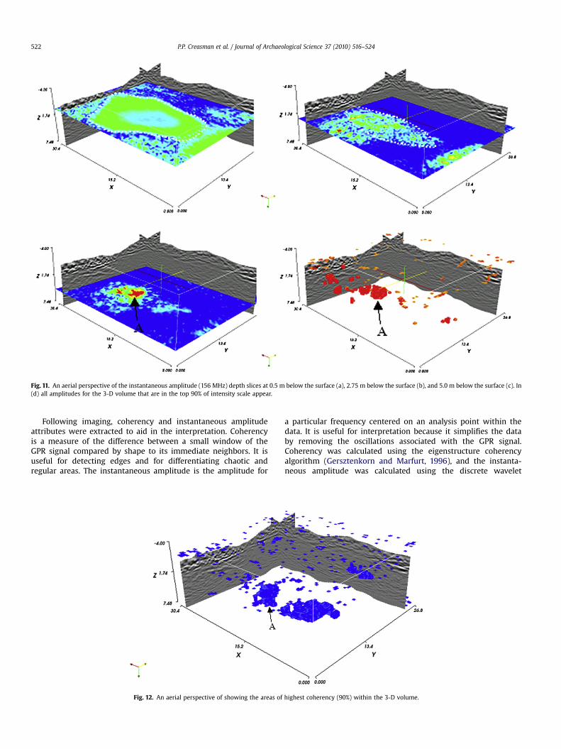
Fig. 11. An aerial perspective of the instantaneous amplitude (156 MHz) depth slices at 0.5 m below the surface (a), 2.75 m below the surface (b), and 5.0 m below the surface (c). In(d) all amplitudes for the 3-D volume that are in the top 90% of intensity scale appear.
P.P. Creasman et al. / Journal of Archaeological Science 37 (2010) 516–524522
Following imaging, coherency and instantaneous amplitudeattributes were extracted to aid in the interpretation. Coherencyis a measure of the difference between a small window of theGPR signal compared by shape to its immediate neighbors. It isuseful for detecting edges and for differentiating chaotic andregular areas. The instantaneous amplitude is the amplitude for
Fig. 12. An aerial perspective of showing the areas of
a particular frequency centered on an analysis point within thedata. It is useful for interpretation because it simplifies the databy removing the oscillations associated with the GPR signal.Coherency was calculated using the eigenstructure coherencyalgorithm (Gersztenkorn and Marfurt, 1996), and the instanta-neous amplitude was calculated using the discrete wavelet
highest coherency (90%) within the 3-D volume.

Table 1Laboratory measurements of dielectric permittivity and electrical conductivity(adapted from Sharma, 1997; Daniels, 2004).
Material type Relative dielectricpermittivitya
Electrical conductivity S/m
Dry sand/gravel 4–10 1E�7 to 1E�3Wet sand/gravel 10–20 1E�3 to 1E�2Dry clay/silt 2–6 0.1 to 1.0Wet clay/silt 7–40 0.1 to 1.0Granite 4–9 1E�07Limestone 4–8 1E�9 to 0.1Air 1 0Fresh water 81 1E�6 to 0.01
a Permittivity constant is 8.85E�12 F/m.
P.P. Creasman et al. / Journal of Archaeological Science 37 (2010) 516–524 523
transform (DWT) using the Morlet wavelet (Chopra and Marfurt,2007).
4. Results
4.1. Interpretation of GPR area 1: the search for the boat
For GPR area 1 (Fig. 6), provide 3-D diagrams of the GPR data.Textures of the imaged data reveal three distinct zones: (1) theoriginal naturally deposited sediments, (2) the debris and backfillassociated with either the original creation of the boat pit in theTwelfth Dynasty and/or the refuse of de Morgan’s excavation of theboat, and (3) the excavated pit for the boat(s) and possibly addi-tional, unidentified structures.
The originally deposited sediments have very low differences inEM contrasts, with a small-scale and irregular texture (Fig. 6)Arelatively continuous reflector demarks the surface between thedebris and backfill and the original sediments across the entire siteat approximately 0.5 m below the current site surface (Fig. 8). Thedebris and backfill typically show higher EM contrast than theoriginal sediments. High-contrast features varying from laterallycontinuous surfaces to a hummocky texture characterize de Mor-gan’s excavated boat pit (Fig. 9).
An east–west profile through the center of the excavated boatpit (Fig. 10).Figs. 7–12 shows some other features apparent in thedata, including two distinct surfaces within or below the boat pit(at depths of 2.75 m and 5.0 m) and a wall presumed to be theeastern wall of the vaulted brickwork structure. At the site, thedecomposed mud brick of this wall remains visible at the surface.
Extracting the instantaneous amplitude attributes from the dataprovides a more simplified view of the imaged data (Fig. 11). In the0.5 m depth slice (Fig. 11a), slice edges of the excavated boat pit areclearly outlined by lower amplitudes. In the 2.75 m depth slice(Fig. 11b), the surface seen in Fig. 10 appears to have an ellipticalshape, similar to that of a boat. This is believed to be the remnantsof the mud-brick support structure for one of the boats excavated in1894 by de Morgan. In the 5.0 m depth slice (Fig. 11c), the strongestcontrasting features are seen, with the peak amplitude corre-sponding to the feature labeled A in Fig. 10. The volume display(Fig. 11d) of the >90% amplitude shows that the largest contrastingfeature is at the 5.0 m level. The coherency attributes extractedfrom the imaged data show the strongest similarity levels (>90%) atthe same 5.0 m level (Fig. 12).
5. Discussion and conclusions
Careful examination of the current GPR images detects no directevidence of boat remains in the area of our survey. One boat pit canbe confirmed; however, two pits were expected, or else one pit largeenough to have contained two boats. The low contrast and small-
scale irregular texture, interpreted as the original sediment deposit,is intact below de Morgan’s backfill pile, providing no evidence fora boat pit dug into the subsurface there. There are small changes intexture and amplitude on the edges of the survey area, but these arelikely due to bias in the images caused by the smaller number ofacquisition points near the edges, which resulted in lower signal-to-noise ratios. Improving the image quality and interpretation ispossible through more refined imaging techniques and the extrac-tion of more attributes; however, most of the potential of the datahas already been realized. The questions of the location and exis-tence of the fifth Dahshur boat remain outstanding.
If a fifth boat was removed from the site, there should beevidence of its removal, presumably in the form of a boat pit; butwhere is the pit? Ground-penetrating radar clearly imaged only oneboat pit, although based on de Morgan’s excavation notes (1895), atleast two should be present in the search area. Given the history ofarchaeological revisitation at the site, specifically circa 1900 (seePatch and Haldane, 1990), it is possible that previous searches foritems of intrinsic value in this area have been thorough enough tohave completely destroyed any evidence of the missing boat, itssupport structure, and its pit.
The survey proved useful in many respects: delineating thedepth and extent of the presumably empty boat pit excavated byde Morgan, structural features, and the strata of previous exca-vations. Being able to determine the depth of the interfacesbetween the original sediment deposit and the backfill and debrisis significant. In regions of the world such as Egypt, heavilyexcavated during periods when modern archaeological methodsand recordkeeping were undergoing development, localizedapplication of GPR could be very useful for determining the statusof areas of interest for reexcavation; the remote-sensing methodsused at Dahshur in 2007 and 2008 can provide for reflexiveinvestigations.
The imaging has also provided information regarding thelocations of walls and surfaces in and around the boat pit. Mostinteresting is the high-contrast, highly coherent area below theboat pit at a subsurface depth of 5 m (see Figs. 10–12), approxi-mately 2.25 m deeper than our interpretation of the boat-pitdepths. Such high contrast and high coherency indicate an arti-ficial feature consisting of materials that differ from the localsediments. It is questionable that de Morgan’s excavation reachedthis. Included at this 5 m deep surface is a small (2 � 2 � 3 m)highly reflective feature labeled A in the aforementioned figures.Archaeological verification of this unknown feature is recom-mended, as no structures other than the boat pits and vaultedchamber are known to neighbor the southwestern corner ofSenwosret III’s pyramid complex and it is not possible to interpretwith certainty what the high-contrast, highly coherent areaobtained from the GPR data represents.
Acknowledgements
This project was made possible by the approval of the SupremeCouncil of Antiquities (Egypt), assistance from Dr Zahi Hawass, andthe exceptional patience and kind permission of Dr Dieter Arnold,as well as the support of Dr Adela Oppenheim and the MetropolitanMuseum of Art’s Egyptian Expedition to Dahshur.
If not for the support of the National Geographic Society/WaittGrants Program, and the Waitt Institute for Discovery, this projectwould not have been possible. Our most sincere gratitude is due alsoto the following: Dr Mark Everett, Department of Geology andGeophysics at Texas A&M University; Mme Amira Kattab of theAmerican Research Center in Egypt’s Cairo office; Institute of NauticalArchaeology; and the Institute of Maritime Research and Discovery.

P.P. Creasman et al. / Journal of Archaeological Science 37 (2010) 516–524524
Appendix A. Supplemental material
Supplementary information for this manuscript can be down-loaded at doi: 10.1016/j.jas.2009.10.013.
References
Abbas, A.M., Kamei, H., Helal, A., Atya, M.A., Shaaban, F.A., 2005. Contribution ofgeophysics to outlining the foundation structure of the Islamic Museum, Cairo.Egypt. Archaeological Prospection 12, 167–176.
American Antiquarian and Oriental Journal, 1902. Ancient boat from the Nile.American Antiquarian and Oriental Journal 24, 187–188.
Arnold, D., 1992. South Cemeteries of Lisht, Vol. III. The Pyramid Complex of Sen-wosret I. Metropolitan Museum of Art, New York. ISBN 0870996126.
Arnold, D., 2002. The Pyramid Complex of Senwosret III at Dahshur: ArchitecturalStudies. Metropolitan Museum of Art, New York. ISBN 0300089309.
Chopra, S., Marfurt, K.J., 2007. Seismic attributes for prospect identification andreservoir characterization. In: Hill, S.J. (Ed.), SEG Geophysical DevelopmentsSeries 11. Society of Exploration Geophysicists, Tulsa, OK.
Conyers, L.B., Goodman, D., 1997. Ground Penetrating Radar: An Introduction forArchaeologists. AltaMira Press, Lanham. ISBN 0761989277.
Creasman, P.P., 2005. The Cairo dahshur boats. Unpublished MA thesis, Texas A&MUniversity, College Station, TX.
Creasman, P.P., Vining, B., Koepnick, S., Doyle, N., 2009. An exploratory geophysicalsurvey at the pyramid complex of Senwosret III at Dahshur, Egypt, in search ofboats. International Journal of Nautical Archaeology 38 (2), 386–399.
Cron, R.L., Johnson, G.B., 1995. De Morgan at Dahshur: excavations in the 12thdynasty pyramids, 1984–95, Part one. Kmt 6.2, 34-43.
Daniels, D.J., 2004. Ground Penetrating Radar. IEE Radar, Sonar, Navigation andAvionics Series 15. The Institution of Engineering and Technology, London. ISBN0863413609.
Demarest, K.R., 1998. Engineering Electromagnetics. Prentice Hall. ISBN 0023285214.De Morgan, J.J., 1895. Fouilles a Dahchour: Mars–Juin 1894. Adolphe Holzhausen,
Vienna, in French.De Morgan, J.J., 1897a. Note sur les travaux du service des antiquites de l’Egypte et
l’Institut Egyptien pendant les annees 1892, 93 et 94. Actes du dixieme congresinternational des orientalistes, session de Geneve 1894. E.J. Brill, Leiden, inFrench, pp. 3-33.
De Morgan, J.J., 1897b. Carte de la necropole: Dahchour, Sakkarah, Abou-Sir. H.Ravon Bey, Le Caire (in French).
De Morgan, J.J., 1903. Fouilles a Dahchour 1894-1895. Adolphe Holzhausen, Vienne(in French).
De Morgan, J.J., 1898. Account of the Work of the Service of Antiquities of Egypt andof the Egyptian Institute During the Years 1892, 1893, and 1894. Annual Reportof the Board of Regents of the Smithsonian Institution July 1896. SmithsonianInstitution/Government Printing Office, Washington DC, , pp. 591–612.
Engheta, N., Papas, C.H., Elachi, C., 1982. Radiation patterns of interfacial dipoleantennas. Radio Science 17, 1557–1566.
Frothingham Jr., A.L., 1895. Archaeological news: summary of recent discoveries andinvestigations: Egypt. American Journal of Archaeology and the History of theFine Arts 10.1, 65–74.
Gersztenkorn, A., Marfurt, K.J., 1996. Eigenstructure based coherence computations,in: SEG Expanded Abstracts. 66th Annual International Meeting, 328–331.
Goodman, D., Hongo, H., Higashi, N., Inaoka, H., Nishimura, Y., 2007. GPR surveyingover burial mounds: correcting for topography and the tilt of the GPR antenna.Near Surface Geophysics 5.6, 383–388.
Grasmueck, M., Weger, R., Horstmeyer, H., 2005. Full-resolution 3D GPR imaging.Geophysics 70.1, K12–K19.
Hafez, M.A., Atya, M.A., Hassan, A.M., Sato, M., Wonick, T., El-Kenawy, A.A., 2008.Shallow geophysical investigations at the Akhmim archaeological site, Suhag,Egypt. Applied Geophysics 5, 136–143.
Haldane, C.W., 1984. The Dashur boats. Unpublished MA thesis, Texas A&MUniversity, College Station, TX.
Hassan, S., 1946. The boats of Dahshur. In: Hassan, S. (Ed.), Excavations at Giza 1.1.Government Press, Cairo 157.
Hawass, Z., 2004. Development of the royal funerary complex. http://www.guardians.net/hawass/mortuary1.htm#boats
Herbich, T., 2003. Archaeological geophysics in Egypt: the Polish contribution.Archaeologia Polona 41, 13–55.
Herbich, T., Hedstrom, D.B., Davis, S.J., 2007. A geophysical survey of AncientPherme: magnetic prospection at an early Christian monastic site in theEgyptian Delta. Journal of the American Research Center in Egypt 43,129–138.
Hesse, A., 1970. Introduction geophysiques et notes techniques. In: Vercoutter, J.(Ed.), Mirgissa. Mission Archeologique Française au Soudan, Paris, pp. 51–121.Vol. 1 (in French).
Jerri, A.J., 1977. The Shannon sampling theorem – its various extensions andapplications: a tutorial review. Proceedings of the IEEE 65, 1565–1596.
Lehmann, F., Green, A.G., 2000. Topographic migration of georadar data: implica-tions for acquisition and processing. Geophysics 65, 836–848.
Lehner, M., 1997. The Complete Pyramids. Thames and Hudson. ISBN 0500050848.Lepsius, C., 1849-1859. Denkmaler aus Aegypten und Aethiopien. 6 parts in 12 plate
volumes. Nicholaische Buchhandlung, Berlin (in German).Moran, M.L., Greenfield, R.J., Arcone, S.A., Delaney, A.J., 2000. Multidimensional GPR
array processing using Kirchhoff migration. Journal of Applied Geophysics 43,281–295.
Patch, D.C., Haldane, C.W., 1990. The Pharaoh’s Boat at the Carnegie. CarnegieMuseum of Natural History, Pittsburgh, PA. ISBN 0911239227.
Porter, B., Moss, R.L.B., 1981. In: Malek, J. (Ed.), Topographical Bibliography ofAncient Egyptian Hieroglyphic Texts, Reliefs and Paintings III2 Memphis Part 2.Saqqara to Dahshur Fascicle 3 (III2.777-1014), second edition. Griffith Institute,Ashmolean Museum, Oxford revised and augmented byISBN 0900416238.
Reisner, G.A., 1913. Models of Ships and Boats. L’Institut Français d’ArcheologieOrientale, Cairo. Catalogue General 4798–4976 et 5034–5200.
Sharma, P.V., 1997. Environmental and Engineering Geophysics. CambridgeUniversity Press, Cambridge. ISBN. 0521572401.
Steffy, J.R., 1998. Wooden Ship Building and the Interpretation of Shipwrecks. TexasA&M University Press, College Station, TX. ISBN 0890965528.
Sternberg, B.K., McGill, J.W., 1995. Archaeology studies in southern Arizona usingground penetrating radar. Journal of Applied Geophysics 3, 209–225.
Streich, R., van der Kruk, J., 2007. Accurate imaging of multicomponent GPR databased on exact radiation patterns. IEEE Transactions on Geosciences andRemote Sensing 45, 93–103.
Taylor, J.H., 2000. Death and the Afterlife in Ancient Egypt. British Museum, London.Tohge, M., Karube, F., Kobayashi, M., Tanaka, A., Ishii, K., 1998. The use of ground
penetrating radar to map an ancient village buried by volcanic eruptions.Journal of Applied Geophysics 40, 49–58.
van der Kruk, J., Wapenaarz, C.P.A., Fokkemaz, J.T., van den Bergz, P.M., 2003. Three-dimensional imaging of multicomponent ground-penetrating radar data.Geophysics 68, 1241–1254.
Ward, C.A., 2000. Sacred and Secular: Ancient Egyptian Ships and Boats. Universityof Pennsylvania Museum, Philadelphia, PA. ISBN 0787271829.
Yilmaz, O., Doherty, S.M., 1987. Seismic Data Processing. Society of ExplorationGeophysicists, Tulsa, OK. ISBN 0931830400.