journal of food engineering - sites.bsyse.wsu.edu
TRANSCRIPT

Journal of Food Engineering 118 (2013) 406–416
Contents lists available at SciVerse ScienceDirect
Journal of Food Engineering
journal homepage: www.elsevier .com/locate / j foodeng
Development of a computer simulation model for processing foodin a microwave assisted thermal sterilization (MATS) system
0260-8774/$ - see front matter � 2013 Elsevier Ltd. All rights reserved.http://dx.doi.org/10.1016/j.jfoodeng.2013.04.021
⇑ Corresponding author.E-mail address: [email protected] (J. Tang).
F.P. Resurreccion Jr. a,d, J. Tang a,⇑, P. Pedrow b, R. Cavalieri c, F. Liu a, Z. Tang a
a Biological Systems Engineering Department, Washington State University, Pullman, WA 99164, USAb School of Electrical Engineering and Computer Science, Washington State University, Pullman, WA 99164, USAc Agricultural Research Center, College of Agricultural, Human, and Natural Resource Sciences, Washington State University, Pullman, WA 99164, USAd Corporate R&D, Graphic Packaging International, Golden, CO 80403, USA
a r t i c l e i n f o a b s t r a c t
Article history:Received 28 November 2012Received in revised form 18 February 2013Accepted 22 April 2013Available online 2 May 2013
Keywords:Microwave heatingComputer simulationChemical marker
The microwave assisted thermal sterilization computer simulation model (MATS-CSM) was developed toimprove the previous computer simulation model for the microwave assisted thermal sterilization(MATS) system. Development of the new MATS-CSM included determination of optimum heating timestep, evaluation of electromagnetic field distribution and the resulting heating pattern in food, and exper-imental validation of heating patterns. It was determined that the minimum number of discretizationthat would not cause immediate divergence of the EM-heat transfer solution was 32 steps correspondingto 97 mm and 5.6 s of displacement and heating time for every step, respectively. Furthermore, this studysuccessfully demonstrated the symmetrical electromagnetic field distribution between top and bottommicrowave entry ports and a staggered electric field pattern from one cavity of the MATS to the next.In addition, MATS-CSM confirmed that incorporating heat diffusion in the simulation model reducesthe difference in hot spot and cold spot temperature by 65%. It also confirmed that water circulationreduces the edge heating effect, as observed in experiments. The heating pattern generated by MATS-CSM was verified experimentally through a chemical marker method. Based on the percent areal crosssection of the weighted average temperature, there were no noticeable differences between the heatingzones generated by the MATS-CSM and by the chemical marker method. The percent areal cross sectionof the cold area 1, cold area 2, and hot area by MATS-CSM were 35%, 25%, and 40%, respectively, and thecold area 1, cold area 2, and hot area by chemical marker method were 35%, 30%, and 35%, respectively.
� 2013 Elsevier Ltd. All rights reserved.
1. Introduction a non-resonant phenomenon caused by the electric field parallel
A significant attribute of processing food in a microwave as-sisted thermal sterilization (MATS) system is the improved qualityof the food due to the reduction of the processing time by as muchas 10 times when compared to conventional heating methods(Brody, 2011; Guan et al., 2002; Tang et al., 2002, 2008). Althoughthe advantages of using microwave energy are obvious, severalchallenges must be overcome to fully utilize microwave energy inthermal sterilization of food. One of which is the problem of unifor-mity in the electromagnetic (EM) field distribution (Metaxas andMeredith, 1993). The fundamental physics of the system pertainingto the design and operating frequency of the microwave cavity aswell as the shape, size, placement, and dielectric properties of foodcan influence uniformity of EM field distribution (Kashyap andWyslouzil, 1977; Ryynanen and Ohlsson, 1996; Romano et al.,2005; Geedipalli et al., 2007). Another notable challenge in usingmicrowave energy is the edge overheating effect in food, which is
to the edge of the food (Risman, 2009).Challenges in using microwave energy were overcome in the
MATS system by designing and fabricating microwave cavities thatoperate in a single-mode with or without load (i.e., food) (Tanget al., 2006; Pathak et al., 2003). This was possible by using a915 MHz microwave source of longer wavelength, instead of themore popular 2450 MHz, allowing for flexibility in the design ofcavities with practical geometry and configuration (Brody, 2011).Since a single-mode cavity has only one resonant mode (Metaxasand Meredith, 1993; Decareau, 1985), the EM field pattern insideis always consistent and predictable.
In the MATS system, to lessen the effect of edge overheating,water is circulated inside the cavities together with the food beingprocessed. The circulating water has three purposes: (1) it acts as aheat sink to reduce the edge overheating in food during microwaveprocesses, (2) it maintains the temperature of the food once itreaches sterilization temperature (Tang et al., 2006), and (3) it actsas a matching medium resulting in a relatively even power deposi-tion profile over the surface of the food (Pathak et al., 2003).

F.P. Resurreccion Jr. et al. / Journal of Food Engineering 118 (2013) 406–416 407
Computer simulation is a widely accepted tool that aids engi-neers in designing microwave ovens (Sundberg et al., 1996; Celuchand Kopyt, 2009; Hossan et al., 2010; Celuch et al., 2011). In devel-oping the MATS system, computer simulation provided a theoreti-cal basis for the design of the geometry of the cavities. Pathak et al.(2003) used a finite-difference time-domain (FDTD) numericalmethod to characterize the microwave field distribution insidethe microwave cavities of MATS. It was demonstrated that the cir-culating water in the cavities helps to level the power distributionwithin the food. Following the work of Pathak et al. (2003), Chenet al. (2008) developed a computer simulation model using a simi-lar FDTD numerical method that included both microwave propa-gation and heat transfer to simulate the continuous operation ofthe MATS system with the purpose of describing the heating pat-tern and location of the cold spot in food packages. Furthermore,Chen et al. (2008) developed a method of controlling the electro-magnetic field distribution by way of placing an Ultem™ slab ofspecific thickness on the narrow wall of the cavities of MATS. Thecomputer simulation model by Chen et al. (2008) was created onlyfor a specific configuration and provides no provision for modifica-tion of the geometry of the cavities and the shape of food packages.Furthermore, considering that MATS is in its commercializationphase, scale-up will undoubtedly require several changes to the ori-ginal configuration necessitating adjustments in the computer sim-ulation. Thus there is a need to revise the tool.
1.1. Microwave assisted thermal sterilization (MATS) system
The pilot scale MATS (Fig. 1) at Washington State University is aclosed system consisting of four sections—preheating, microwaveheating, holding and cooling—arranged in series representing thefour sequential processing steps. Each section has a separate watercirculation system that consists of a pressurized tank and plate heatexchanger to control water flow at a pre-set temperature. A pock-eted mesh conveyor belt made of non-metallic material extendingfrom one end of the preheating section to the other end of the cool-ing section conveys food trays or pouches across different sectionsof MATS. This study is primarily concerned with the microwaveheating section of the MATS. The MW heating section consists offour connected rectangular microwave cavities (i.e., cavity 1, cavity2, cavity 3, and cavity 4) (Fig. 1). Each of the four cavities is con-nected to a separate corresponding microwave generator (generator1, generator 2, generator 3, and generator 4), with stub tunners tominimize reflected power.
1.2. Features of MATS-CSM
In this study, the new computer simulation model is referred toas the MATS-CSM (microwave assisted thermal sterilization com-puter simulation model). The MATS-CSM employs a similar numer-ical approach as described by Chen et al. (2008) but also addressesthe limitations of the previous version. Listed below are the criticallimitations of Chen et al.’s (2008) computer simulation model thatwere the focus of the revisions done in the MATS-CSM:
Fig. 1. Microwave assisted thermal sterilization (MATS) system diagram showi
� In the simulation model of Chen et al. (2008), the foodpackages were monitored as if they were equally spacedas they traveled through the four heating cavities with onlysix discrete steps per cavity (total of 24 steps for the fourcavities) representing a pseudo-moving package. Thisscheme limits the number of discrete steps since it wouldnot allow food packages to simultaneously and adjacentlyoccupy an analytical zone. In this study, the MATS-CSMsimulates moving food by replacing the media parameterof the volume that will be occupied on the next discretestep with the media parameter of the food, thereby elimi-nating the limit to the number of discrete steps.
� Chen et al. (2008) describe a two-cavity system on a one-cavity simulation model for an earlier version of MATS byexecuting the simulation twice (i.e., first simulation forthe first cavity and second simulation for the second cav-ity). The grid for the finite difference calculation was ter-minated using a perfect electric conductor (PEC) resultingin almost a 2% error in EM field calculation per simulation(Chen et al., 2007). In this study, the MATS-CSM includesfour cavities in one model eliminating the need for multi-ple executions of simulation. Furthermore, the right endof the first cavity and the left end of the fourth cavity ofthe MATS-CSM are extended such that the PEC termina-tion is far from the bulk of the computational domain.Doing so reduces the error due to the PEC terminationdown to <0.5%.
� The simulation in Chen et al. (2008) requires node trans-formation to synchronize electromagnetic node with thetemperature node for heat transfer. Using the new ver-sion of QuickWave™ v7.5 to create the MATS-CSM, ther-mal-FDTD uses the same mesh as with EM-FDTD (Celuchet al., 2011), thereby eliminating the need for node trans-formation and avoiding numerical diffusion error (Kopytand Celuch, 2003, 2004).
� The heat transfer equation in Chen et al.’s (2008) simula-tion model is very specific to the node defined in the model.If there is a change in meshing, modification in the geome-try of the cavity, or change in size, shape and compositionof food package geometry, the heat transfer equation ofChen et al. (2008) will no longer work. In the MATS-CSM,for flexibility, all components are defined in an individualobject with variable parameters that can be changeddepending on the objectives of the user, and the mesh auto-matically readjusts to accommodate changes in theparameters.
1.3. MATS-CSM assumptions
1. The electromagnetic simulation region includes onlycavities (not waveguides and only the exit apertures ofthe horn antennas which become ports in our simula-
ng various sections: preheating, microwave heating, holding, and cooling.

408 F.P. Resurreccion Jr. et al. / Journal of Food Engineering 118 (2013) 406–416
tion). By way of the uniqueness theorem (Balanis, 1989),only the E-field in the plane of the input ports must bespecified. Thus, incident and reflected fields in the hornantenna volume are not needed.
2. Since reflection occurs in the actual MATS system, the totalmicrowave energy injected into each cavity in MATS-CSMis only the net transmitted microwave energy measured inthe MATS system.
3. The transmitted microwave energy in the side arm of theE-plane tee-junction is evenly divided into its coplanararms (i.e., Power/2) whose amplitude is equal to
ffiffiffiffiffiffi2Pp
. Thisassumption follows an ideal lossless reciprocal E-planetee-junction (Pozar, 2005).
4. Waveguide parts such as elbows, tee-junction, spaces,circulator, probe-tuner, and directional coupler do notalter the characteristics of the electromagnetic wave(Chen et al., 2008).
5. Non-solid components of food sample (Alfredo sauce),due to its high viscosity and relatively small quantity,is assumed to have insignificant mobility. Therefore,heat transfer occurring within the Alfredo sauce andthe Alfredo sauce – whey protein gel (WPG) boundaryis assumed to be purely conductive.
6. Each element (characterized by a certain medium) occupy-ing a certain volume is assumed to be linear, homoge-neous, isotropic, and non-dispersive.
7. The turbulent condition of circulating water in the cavitiesis considered in MATS-CSM by defining the convectiveheat transfer coefficient between the boundary of circulat-ing water and food.
1.4. Objective
The general objective of this study is to create a new computersimulation model for the microwave assisted thermal sterilization(MATS) system (which will be known as the MATS-CSM) that con-siders the coupled solution of electromagnetic field and heat trans-fer phenomena in food packages moving in multiple microwavecavities. The specific objectives of this study are:
� To create a flexible computer simulation model that is able toaccommodate future modification in the MATS system. TheMATS-CSM should be able to consider a wide range of foodmaterials and package geometries, including both homoge-neous and heterogeneous types of food.� To describe electromagnetic field distribution inside microwave
cavities with and without food packages.� To determine the acceptable discrete number of time steps for
the movement of food.� To compare heating patterns in certain food packages consider-
ing EM-only solution versus EM-heat transfer solution.� To validate the heating pattern output of the MATS-CSM
through the chemical marker method.
2. Experimental procedure
2.1. Finite-difference time-domain (FDTD) governing equations
The set of four Maxwell equations that govern the general char-acteristics of electromagnetic waves traveling in a certain mediumare:
r � D!¼ q ð1Þ
r � B!¼ 0 ð2Þ
r� E!¼ �l @H
!
@tð3Þ
r � H!¼ r E
!þ e@ E!
@tð4Þ
where D!
, B!
, E!
, and H!
are the electric flux density, magnetic fluxdensity, electric field intensity, and magnetic field intensity, respec-tively. The r, l, and e are the electric conductivity, permeability,and permittivity of the material, respectively (Guru and Hiziroglu,2004). In 3-dimensional (3D) space Eqs. (3) and (4) can be writtenas:
r� E!¼
ax ay az
@@x
@@y
@@z
Ex Ey Ez
�������
�������¼ �l @H
!
@tð5Þ
r � H!¼
ax ay az
@@x
@@y
@@z
Hx Hy Hz
�������
�������¼ r E!þ e
@ E!
@tð6Þ
For irregular or complex geometry, there is no closed-form solutionto Eqs. (5) and (6) therefore; the most appropriate approach is tosolve the equation numerically. The numerical approach works bydiscretizing the irregular or complex geometry (known as the com-putational volume) into cells or regular geometries. Finite-differ-ence time-domain (FDTD) is a common numerical method forelectromagnetic problems designed specifically to solve the timedifferentiated Maxwell’s curl equations (Eqs. (5) and (6)). The FDTDmethod is a time-marching procedure that simulates the continu-ous electromagnetic waves in a finite spatial region while time-stepping continues until a desired simulation time is achieved ora stable field pattern is established (Taflove and Hagness, 2005).The unit cell in FDTD has a size equal to Dx, Dy, and Dz in the x,y, and z direction, respectively, at a given time step Dt. Consideringthe coordinate of a unit cell as grid point (m, n, p), the x, y, and z dis-tance of any grid point would be x = mDx, y = nDy, and z = pDz. Dis-cretization of time follows in the same manner wherein a certainpoint in time q at the grid corresponds to a certain time by consid-ering a time step Dt (i.e., t = qDt).
In FDTD, the linear equation representation of the partial differ-ential equation with respect to time is given by:
@Hi
@t¼ Hqþ1=2
i ðm;n; pÞ � Hq�1=2i ðm;n; pÞ
Dt
@Ei
@t¼ Eqþ1
i ðm;n;pÞ � Hqi ðm;n;pÞ
Dtð7Þ
and the linear equation representation of the partial differentialequation with respect to position considering central difference isgiven by:
@Fi
@x¼ Fq
i ðmþ 1;n;pÞ � Fqi ðm;n;pÞ
Dx
@Fi
@y¼ Fq
i ðm;nþ 1;pÞ � Fqi ðm;n;pÞ
Dy
@Fi
@z¼ Fq
i ðm;n; pþ 1Þ � Fqi ðm;n;pÞ
Dzð8Þ
where F is either electric, E, or magnetic H field component.The electric field is dependent on the updated magnetic field
ðHqþ1=2i Þ and for the next time step on the grid, the magnetic field
would be dependent on the updated electric field ðEqþ1i Þ. The

F.P. Resurreccion Jr. et al. / Journal of Food Engineering 118 (2013) 406–416 409
routine of updating fields mimics a time-marching procedure of asimulating electromagnetic fields as described by Taflove (2005).The equations of the update of the field on the next time step arethe following (Taflove and Hagness, 2005):
Hqþ1
2x m;nþ1
2;pþ1
2
� �¼H
q�12
x m;nþ12;pþ1
2
� �
þ DtlDz
Eqy m;nþ1
2;pþ1
� ��Eq
y m;nþ12;p
� �� ��
� DtlDy
Eqz ðm;nþ1;pþ1
2Þ�Eq
z m;n;pþ12
� �� �ð9Þ
Hqþ1
2y mþ1
2;n;pþ1
2
� �¼H
q�12
y mþ12;n;pþ1
2
� �
þ DtlDx
Eqz mþ1;n;pþ1
2
� ��Eq
z m;n;pþ12
� �� ��
� DtlDz
Eqx mþ1
2;n;pþ1
� ��Eq
x mþ12;n;p
� �� �ð10Þ
Hqþ1
2z mþ1
2;nþ1
2;p
� �¼H
q�12
z mþ12;nþ1
2;p
� �
þ DtlDy
Eqx mþ1
2;nþ1;p
� ��Eq
x mþ12;n;p
� �� ��
� DtlDx
Eqy mþ1;nþ1
2;p
� ��Eq
y m;nþ12;p
� �� �ð11Þ
Eqþ1x mþ1
2;n;p
� �¼
1�rDt2e
1þrDt2e
Eqx mþ1
2;n;p
� �
þ 11þrDt
2e
DteDy
Hqþ1
2z mþ1
2;nþ1
2;p
� ��H
qþ12
z mþ12;n�1
2;p
� �� ��
� DteDz
Hqþ1
2y mþ1
2;n;pþ1
2
� ��H
qþ12
y mþ12;n;p�1
2
� �� �
ð12Þ
Eqþ1y m;nþ1
2;p
� �¼
1�rDt2e
1þrDt2e
Eqy m;nþ1
2;p
� �
þ 11þrDt
2e
DteDz
Hqþ1
2x m;nþ1
2;pþ1
2
� ��H
qþ12
x m;nþ12;p�1
2
� �� ��
� DteDx
Hqþ1
2z mþ1
2;nþ1
2;p
� ��H
qþ12
y m�12;nþ1
2;p
� �� �
ð13Þ
Eqþ1z m;n;pþ1
2
� �¼
1�rDt2e
1þrDt2e
Eqz m;n;pþ1
2
� �
þ 11þ rDt
2e
DteDx
Hqþ1
2y mþ1
2;n;pþ1
2
� ��H
qþ12
y m�12;n;pþ1
2
� �� ��
� DteDy
Hqþ1
2x m;nþ1
2;pþ1
2
� ��H
qþ12
x m;n�12;pþ1
2
� �� �
ð14Þ
2.2. Stability criteria for FDTD
The stability of FDTD numerical solution was described by Taf-love (1988) and was simplified by Sheen et al. (1990) by setting thespatial step size (d) arbitrarily equal to one of the dimensions in theunit cell. In this study, Dx is chosen to be equal to d, and the ratio ofthe other two dimensions with respect to Dx are; ry = Dy/Dx; andrz = Dz/Dx:
S ¼ cDtd6
1ffiffiffiffiffiffiffiffiffiffiffiffiffiffiffiffiffiffiffiffiffi1þ 1
r2yþ 1
r2z
q ð15Þ
where S is the Courant number and c is the speed of light. TheMATS-CSM was discretized such that the unit cell had a maximumsize of 4 mm by 4 mm by 16 mm. These values gave an ry = 1 andrz = 4.0. The stability index of the entire computational volume
would be 0.6963, which is greater than the Courant limit for a 3Dmodel (i.e., 1=
ffiffiffi3p� 0:5574) (Taflove, 2005); hence, Eq. (15) was sat-
isfied. Furthermore, the mesh size for the dielectric media (i.e., foodand water in the cavities) in the MATS-CSM was refined to have asmaller cell size complying with the 10 points per wavelength rule(Pathak et al., 2003).
2.3. Components of MATS-CSM
Since coupled microwave and heat transfer heating occurs onlyin the heating section of the MATS, other sections (i.e., preheating,holding and cooling sections) are not included in the MATS-CSM.Fig. 2 depicts the computational volume of the MATS-CSM. Forsimplicity, the waveguides that connect the cavities to their desig-nated generators (e.g, cavity 1 waveguide connection to generator1) are not included. Instead, they were replaced by two ports lo-cated at the top and bottom portion of the horn applicator(Fig. 2B(a)).
2.4. Food representation in MATS-CSM
Whey protein gel (WPG) containing 75.4% moisture, 0.6% salt,1% D-ribose, 18% WPG-392, and 5% WPG-895I was used as themodel food. The procedure described by Pandit et al. (2007a,b) inpreparing WPG was implemented in this study. The dielectricand thermal property of WPG was used to define food as a lossymaterial in the MATS-CSM. The whey protein gel slab (Fig. 2B(c))set to move along different sections of MATS was represented inthe simulation model by drawing an object consisting of: (a) a slabelement in the middle with dimensions of 52 � 95 � 16 mm (i.e.,x,y,z); (b) four-4 half cylinder elements attached to the four sidesof the slab element, each with a radius equal to 16 mm and alength equal to the length of the side of the slab to which the halfcylinder was attached; and (c) four-4 quarter sphere elements at-tached to the four corners of the slab element with radii equal to16 mm.
Typical food products in pouches previously processed in theMATS contain sauce. To consider the sauce in the MATS-CSM mod-el, the dielectric and thermal properties of commercially availableBertolli™ Alfredo sauce (Englewood Cliffs, NJ 07632) was used. Theobject representing Alfredo sauce was incorporated in the model inthe same manner as the WPG. The final dimensions of the Alfredosauce were (95 � 140 � 16 mm) (i.e., x,y,z). The volume occupiedby the object representing WPG (94 � 127 � 16 mm) was embed-ded in the object representing the Alfredo sauce, displacing anequal volume occupied by the Alfredo sauce.
2.5. Dielectric and thermal property of WPG and Alfredo sauce
Dielectric property (DP) of WPG and Bertolli™ Alfredo saucewas measured using Hewlett-Packard 8752C network analyzer(Palo Alto, CA 94304). The dielectric property system and method-ology described by Wang et al. (2003) was used in this study. Ther-mal properties of WPG and Bertolli™ Alfredo sauce were measuredusing a Decagon™ KD2-pro (Pullman, WA 99163). The specific heatand thermal conductivity were measured using the double needlemethod (Campbell et al., 1991). For the measurement of specificheat and thermal conductivity, a solid WPG sample was placed in-side the same test cell used for dielectric property measurementdescribed in Wang et al. (2003). The test cell was connected to acirculating oil bath for control of the sample temperature. The dou-ble needle probe of the Decagon™ KD2-Pro consisted of a line heatsource at a fixed distance parallel to a temperature sensor carefullyinserted into the WPG sample inside the test cell. As prescribed byDecagon, in using KD2-Pro, the pump for the circulating oil bathwas turned off just before taking a measurement, to ensure no

Fig. 2. (A) A representative cavity showing the waveguide configuration. (B) Simplified computational volume of MATS-CSM consisting of four microwave cavities and fourpairs of horn applicators: (a) location of microwave input port (total of 8 ports); (b) direction of movement of pouch; (c) initial location of pouch.
Table 1Different input ports in MATS-CSM.
Cavity Ports Frequency(MHz)
Net TransmittedPower (kW)
Amplitude(V/m)
Cavity 1 topPortCl 912.1 6.40 80.0bottomPortCl
Cavity 2 topPortC2 916.5 5.56 74.6bottomPortC2
Cavity 3 topPortC3 905.6 2.51 50.1bottomPortC3
Cavity 4 topPortC4 903.1 2.59 50.9bottomPortC4
410 F.P. Resurreccion Jr. et al. / Journal of Food Engineering 118 (2013) 406–416
mechanical vibration interfered.The dielectric and thermal prop-erty measurement was made over a temperature range of 20–120 �C with 20 �C and 10 �C increment, respectively. Furthermore,using the measured data, dielectric and thermal properties of WPGand Alfredo sauce were extrapolated up to 150 �C and interpolatedat 10 �C increment. Cubic spline or piecewise-polynomial approxi-mation (Burden and Faires, 2005) was used to extrapolate andinterpolate data points.
2.6. Input ports and designation of power level
Using FDTD to solve the electromagnetic equations on micro-wave heating requires definition of a microwave source, and dissi-pation of microwave power as heat in the load (i.e., the food). Forthe source of microwaves, typically, an input port is defined at alocation within the computational volume. An input port coversan area in the computational volume, wherein the electric andmagnetic field at a selected frequency is triggered at a knownamplitude and excitation waveform (QWED, 2009). In the MATS-CSM there are eight input ports consisting of four top-ports andfour bottom-ports (i.e. two ports for each cavity). Ports were drawnwithin the top and bottom standard WR975 waveguide attached to
the tapered end of every horn (Fig. 2B(a)). The parameter settingsof ports are summarized in Table 1.
The equivalent power injected at the input ports (Fig. 2B(a)) de-pends on the amplitude of the electric fields. Given the actual time-averaged power available from the microwave source (i.e., magne-tron), the amplitude of the electric field at every input port shouldbe equal to the square root of the time-maximum power (QWED,2009):
A ¼ffiffiffiffiffiffi2Pp
ð16Þ
where A is the amplitude of the electric field in the input port, P isthe time-average power and 2P is the time-maximum power avail-able from the source. Since there is a microwave reflection in the ac-tual MATS system, the amplitude of the electric field at the ports inthe simulation model was adjusted accordingly by considering onlythe net transmitted power. Using directional couplers manufac-tured by Ferrite Microwave, Inc. (Nashua, NH 03060), reflectedpower was measured for each cavity and only the correspondingtransmitted powers (Table 1) were used in the MATS-CSM model.The equation for time-average power was given by Poynting’s The-orem (Balanis, 1989):
P ¼ 12
Rð E!� H
!�Þ ð17Þ
where P is the time-average power and the real part of the crossproduct of the electric field ð E
!Þ and the conjugate of magnetic fieldðH!�Þ is the time-maximum power.
Dissipated power as heat ð}v Þwas derived from Eq. (17) by con-sidering a closed surface of volume to which the power will be dis-sipated (e.g., the surface of the food):
}v ¼ 2pf e0e00r jE2j ð18Þ
The frequency (f) of generators providing microwave energy wasmeasured using a B&K Precision TM-6250 handheld spectrum ana-lyzer with AN-301 antenna (Yorba Linda, CA 92887). The tabulatedfrequencies in Table 1 are the average frequency of each generatormonitored for a period of one year (measured every other month).
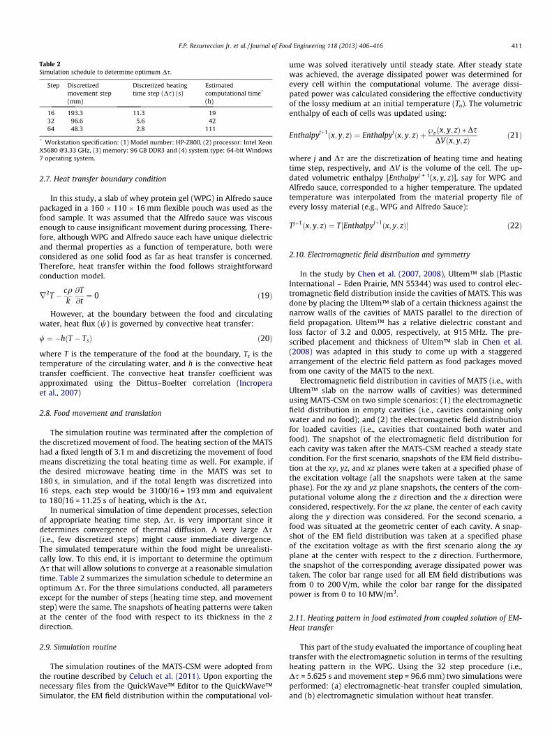
Table 2Simulation schedule to determine optimum Ds.
Step Discretizedmovement step(mm)
Discretized heatingtime step (Ds) (s)
Estimatedcomputational time*
(h)
16 193.3 11.3 1932 96.6 5.6 4264 48.3 2.8 111
* Workstation specification: (1) Model number: HP-Z800, (2) processor: Intel XeonX5680 @3.33 GHz, (3) memory: 96 GB DDR3 and (4) system type: 64-bit Windows7 operating system.
F.P. Resurreccion Jr. et al. / Journal of Food Engineering 118 (2013) 406–416 411
2.7. Heat transfer boundary condition
In this study, a slab of whey protein gel (WPG) in Alfredo saucepackaged in a 160 � 110 � 16 mm flexible pouch was used as thefood sample. It was assumed that the Alfredo sauce was viscousenough to cause insignificant movement during processing. There-fore, although WPG and Alfredo sauce each have unique dielectricand thermal properties as a function of temperature, both wereconsidered as one solid food as far as heat transfer is concerned.Therefore, heat transfer within the food follows straightforwardconduction model.
r2T � cqk@T@t¼ 0 ð19Þ
However, at the boundary between the food and circulatingwater, heat flux (w) is governed by convective heat transfer:
w ¼ �hðT � TsÞ ð20Þ
where T is the temperature of the food at the boundary, Ts is thetemperature of the circulating water, and h is the convective heattransfer coefficient. The convective heat transfer coefficient wasapproximated using the Dittus–Boelter correlation (Incroperaet al., 2007)
2.8. Food movement and translation
The simulation routine was terminated after the completion ofthe discretized movement of food. The heating section of the MATShad a fixed length of 3.1 m and discretizing the movement of foodmeans discretizing the total heating time as well. For example, ifthe desired microwave heating time in the MATS was set to180 s, in simulation, and if the total length was discretized into16 steps, each step would be 3100/16 = 193 mm and equivalentto 180/16 = 11.25 s of heating, which is the Ds.
In numerical simulation of time dependent processes, selectionof appropriate heating time step, Ds, is very important since itdetermines convergence of thermal diffusion. A very large Ds(i.e., few discretized steps) might cause immediate divergence.The simulated temperature within the food might be unrealisti-cally low. To this end, it is important to determine the optimumDs that will allow solutions to converge at a reasonable simulationtime. Table 2 summarizes the simulation schedule to determine anoptimum Ds. For the three simulations conducted, all parametersexcept for the number of steps (heating time step, and movementstep) were the same. The snapshots of heating patterns were takenat the center of the food with respect to its thickness in the zdirection.
2.9. Simulation routine
The simulation routines of the MATS-CSM were adopted fromthe routine described by Celuch et al. (2011). Upon exporting thenecessary files from the QuickWave™ Editor to the QuickWave™Simulator, the EM field distribution within the computational vol-
ume was solved iteratively until steady state. After steady statewas achieved, the average dissipated power was determined forevery cell within the computational volume. The average dissi-pated power was calculated considering the effective conductivityof the lossy medium at an initial temperature (To). The volumetricenthalpy of each of cells was updated using:
Enthalpyjþ1ðx; y; zÞ ¼ Enthalpyjðx; y; zÞ þ }vðx; y; zÞ � DsDVðx; y; zÞ ð21Þ
where j and Ds are the discretization of heating time and heatingtime step, respectively, and DV is the volume of the cell. The up-dated volumetric enthalpy [Enthalpyj + 1(x, y, z)], say for WPG andAlfredo sauce, corresponded to a higher temperature. The updatedtemperature was interpolated from the material property file ofevery lossy material (e.g., WPG and Alfredo Sauce):
Tjþ1ðx; y; zÞ ¼ T½Enthalpyjþ1ðx; y; zÞ� ð22Þ
2.10. Electromagnetic field distribution and symmetry
In the study by Chen et al. (2007, 2008), Ultem™ slab (PlasticInternational – Eden Prairie, MN 55344) was used to control elec-tromagnetic field distribution inside the cavities of MATS. This wasdone by placing the Ultem™ slab of a certain thickness against thenarrow walls of the cavities of MATS parallel to the direction offield propagation. Ultem™ has a relative dielectric constant andloss factor of 3.2 and 0.005, respectively, at 915 MHz. The pre-scribed placement and thickness of Ultem™ slab in Chen et al.(2008) was adapted in this study to come up with a staggeredarrangement of the electric field pattern as food packages movedfrom one cavity of the MATS to the next.
Electromagnetic field distribution in cavities of MATS (i.e., withUltem™ slab on the narrow walls of cavities) was determinedusing MATS-CSM on two simple scenarios: (1) the electromagneticfield distribution in empty cavities (i.e., cavities containing onlywater and no food); and (2) the electromagnetic field distributionfor loaded cavities (i.e., cavities that contained both water andfood). The snapshot of the electromagnetic field distribution foreach cavity was taken after the MATS-CSM reached a steady statecondition. For the first scenario, snapshots of the EM field distribu-tion at the xy, yz, and xz planes were taken at a specified phase ofthe excitation voltage (all the snapshots were taken at the samephase). For the xy and yz plane snapshots, the centers of the com-putational volume along the z direction and the x direction wereconsidered, respectively. For the xz plane, the center of each cavityalong the y direction was considered. For the second scenario, afood was situated at the geometric center of each cavity. A snap-shot of the EM field distribution was taken at a specified phaseof the excitation voltage as with the first scenario along the xyplane at the center with respect to the z direction. Furthermore,the snapshot of the corresponding average dissipated power wastaken. The color bar range used for all EM field distributions wasfrom 0 to 200 V/m, while the color bar range for the dissipatedpower is from 0 to 10 MW/m3.
2.11. Heating pattern in food estimated from coupled solution of EM-Heat transfer
This part of the study evaluated the importance of coupling heattransfer with the electromagnetic solution in terms of the resultingheating pattern in the WPG. Using the 32 step procedure (i.e.,Ds = 5.625 s and movement step = 96.6 mm) two simulations wereperformed: (a) electromagnetic-heat transfer coupled simulation,and (b) electromagnetic simulation without heat transfer.

412 F.P. Resurreccion Jr. et al. / Journal of Food Engineering 118 (2013) 406–416
(a) For the electromagnetic-heat transfer coupled simulation,the convective heat transfer coefficient (h) used was115 W/m2 K calculated using Dittus–Boelter correlation(Incropera et al., 2007).
(b) For the simulation without heat diffusion, only the dissi-pated power from the microwave energy was used as thesource heat. Therefore, the boundary condition betweenthe water-Alfredo sauce and the water-WPG was adiabatic.
2.12. Validation of the MATS-CSM using the chemical marker method
To validate computer simulation results, a chemical markermethod on WPG was used (Pandit et al., 2007a,b). A 162 ± 5 g sam-ple of WPG was cut into a slab with dimensions of84 � 127 � 16 mm and packed into a 237 mL flexible pouch with65 ± 1 g of Alfredo sauce. Six (6) sample pouches were loaded ontothe microwave belt through the door and moved to the preheatingsection of the MATS. After 30 min of preheating at 70–72 �C, thegenerators powering the MATS, at the setting described in Table 1,were activated. The gauge pressure inside the MATS was main-tained at 234.4 kPa. The temperature within the heating and hold-ing sections was maintained at 122 �C and the cooling section at20 �C. The belt holding the pouches of the WPG was moved at aspeed of 1.7 cm/s, allowing transition from preheating, heating,holding and finally to the cooling section. This translates into3 min (180 s) of microwave heating. The WPG inside the pouchwas allowed to cool in the cooling section for 5 min before retriev-ing it through the cooling section door.
The heating patterns of six processed samples of WPG 16 mmthick slabs were determined using the computer image analysis
Table 3Dielectric properties at 915 MHz and thermal properties of whey protein gel (WPG).
Temperature (�C) Dielectric constant e0 (unit less) Loss factor e00 (unit less)
20 52.91 ± 2.49 23.58 ± 2.7540 51.76 ± 0.99 29.26 ± 1.0160 50.62 ± 0.77 34.85 ± 1.5370 50.03a 39.75a
80 49.35 ± 1.45 41.68 ± 1.9790 48.89a 46.76a
100 48.11 ± 1.74 50.73 ± 1.74110 47.76a 53.77a
120 47.42 ± 1.15 58.40 ± 3.02130 46.63b 60.78b
140 46.06b 64.28b
150 45.49b 67.79b
a Interpolated values.b Extrapolated values.
Table 4Dielectric properties at 915 MHz and thermal properties of Alfredo sauce.
Temperature (�C) Dielectric constant e0 (unit less) Loss factor e00
(unit less)Effe2pf
20 55.11 ± 0.45 43.09 ± 3.08 2.1940 52.60 ± 0.32 57.44 ± 1.29 2.9260 49.67 ± 0.52 73.52 ± 1.96 3.74
70a 48.56a 81.20a 4.1380 47.06 ± 0.69 88.88 ± 2.94 4.52
90a 45.91a 97.03a 4.94100 44.14 ± 1.36 105.68 ± 3.29 5.38
110a 43.26a 113.15a 5.76120 41.47 ± 1.91 120.98 ± 2.86 6.16
130b 40.61b 129.53b 6.59140b 39.28b 137.83b 7.02150b 37.96b 146.19b 7.44
a Interpolated values.b Extrapolated values.
method as part of the chemical marker method described by Panditet al. (2006, 2007a,b). In brief, each sample of processed WPG wascut in the middle layer along its thickness into two halves of 8 mmthickness with the aid of 8 mm spacer. Using a high definition cam-era (Nikon™ D70 with AF-S DX NIKKOR 18-55 mm f/3.5–5.6 G VRlens) (Nikon Inc. Melville, NY 11747) images from the cut layerin the center of the WPG (i.e, the xy plane) were taken and pre-pared for color analysis. Adobe Photoshop™ CS4 (Adobe SystemsIncorporated, 345 Park Avenue San Jose, CA 95110) was used toprepare the images, and IMAQ Vision, a part of the library of Lab-VIEW (National Instrument product, Austin, TX 78759) was usedto determine the RBG equivalent of browning in WPG. Browningin the WPG was produced as a result of the non-enzymatic reactionbetween sugar (D-ribose) and protein (WPG 392 and WPG 895-I)(Lau et al., 2003; Pandit et al., 2006).
Validation of the heating pattern was conducted by comparingthe prominent temperature zones in a given area in the heatingpattern of the chemical marker method, and mapping it with theresult generated by the MATS-CSM. The location of the tempera-ture zones and the weighted average of temperature from the arealcross section in a given zone was the basis for validation.
3. Results and discussion
3.1. Dielectric and thermal property of materials
The dielectric properties at 915 MHz and thermal properties ofthe whey protein gel (WPG) and the Alfredo sauce are summarizedin Tables 3 and 4 respectively. Values corresponding to 20 �C, 40 �C,60 �C, 80 �C, 100 �C, and 120 �C were measured. Other values were
Effective conductivity2pfe0e00 (S/m)
Specific heat(kJ/kg �C)
Thermal conductivity(W/m �C)
Enthalpy(MJ/m3)
1.20 2.94b 0.40b –1.49 3.08b 0.45b –1.77 3.21 ± 0.11 0.50 ± 0.02 –2.02 3.28 ± 0.18 0.52 ± 0.04 02.12 3.35 ± 0.04 0.54 ± 0.01 26.772.38 3.41 ± 0.03 0.56 ± 0.01 60.912.58 3.48 ± 0.06 0.57 ± 0.01 95.722.74 3.55 ± 0.02 0.59 ± 0.01 131.212.97 3.62 ± 0.10 0.60 ± 0.01 167.373.09 3.68b 0.61b 204.203.27 3.75b 0.62b 241.703.45 3.82b 0.63b 279.87
ctive conductivitye0e00 (S/m)
Specific heat(kJ/kg �C)
Thermal conductivity(W/m �C)
Enthalpy(MJ/m3)
3.73 0.514 –3.62 0.522 –3.64 0.546 –3.59 0.555 0.003.52 0.550 35.223.55 0.552 70.693.54 0.552 106.083.61 0.558 142.143.73 0.572 179.433.92 0.597 218.604.16 0.629 260.164.45 0.671 304.68

Fig. 3. Electric field distribution (range from 0 to 200 V/m) in the xy plane at the center of the cavity for: (a) loaded cavities, and (b) unloaded cavities. Dissipated powerdensity (range from 0 to 10 MW/m3) in the xy plane at the center of the cavity for: (c) loaded cavities, and (d) unloaded cavities.
Fig. 4. Electric field distribution in the xz, and yz plane. The xz plane was taken at the center with respect to y axis. The yz plane was taken at the geometric center of eachcavity x axis.
F.P. Resurreccion Jr. et al. / Journal of Food Engineering 118 (2013) 406–416 413
either interpolated or extrapolated from the measured properties.These data were used to define the food as lossy materials (WPGand Alfredo sauce) in the MATS-CSM.
3.2. Electromagnetic field distribution and symmetry
Fig. 3 shows the electric field distribution (V/m) at steady statealong the xy plane at the center of the cavity traversing the centerof the food with respect to the z axis. Fig. 3a includes water andfood pouches located at the center of each cavity. Fig. 3b showsthe electric field distribution in circulating water without food.From Fig. 3b, a consistent electric field distribution was observedat a given phase within the cavities considering the frequenciesand power settings of generators described in Table 1. Thus, inevery cavity the electric field distribution is predictable and sym-
metrical along the xy plane. With the presence of food (Fig. 3a),the electric field distribution was still predictable and exhibited asimilar pattern at a given phase as shown in Fig. 3b.
The placing of the Ultem™ bars on the walls of each cavity wassuccessful in creating a staggered electric field distribution forevery cavity (Chen et al., 2008). For example, in cavity 1, the E fieldwas concentrated at the center, then in cavity 2, the E field wasconcentrated along the sides of the food as shown by three stripsof E field pattern, then in the center again for cavity 3, and finallyat the side again for cavity 4 (Fig. 3b). The effect of the staggeredelectric field distribution produced a relatively uniform heatingpattern in the food as it traversed the four cavities.
The staggered arrangement of the electric field is more visible inthe dissipated power distribution (Fig. 3c and d). In this illustra-tion, in cavity 1, the power was mostly dissipated toward the

Fig. 5. MATS-CSM result for temperature distribution in WPG using differentheating time step (16 step, 32 step, and 64 step). The first column represent theinitial temperature of the food (control), and the second, third, fourth and fifthcolumn show the heating pattern of the food at the exit of first, second, third, andfourth, cavity respectively.
414 F.P. Resurreccion Jr. et al. / Journal of Food Engineering 118 (2013) 406–416
middle of the food. For cavity 2, the power was dissipated horizon-tally along the side of the food, for cavity 3 toward the middle ofthe food, and finally for cavity 4 toward the side again.
The xz and yz plane views of the electromagnetic field distribu-tion (Fig. 4) show the symmetry of the electric field in the z direc-tion. Since the pattern is symmetrical, the two electric fields fromthe top and bottom port of each cavity are in-phase. Fig. 4 alsoillustrates the standing wave patterns inside the cavities (i.e., areaunder the red markings). The three distinct horizontal lines at thecenter of each cavity are the standing wave pattern resulting fromthe interaction of the incident field from the top and bottom horn.
Fig. 6. Comparison of heating pattern for electromagnetic coupled heat transfer simudiffusion). Both simulations were executed on a 32-step simulation.
Fig. 7. Six (6) replicates of heating pattern in whey protein gel (WPG) determined througwith respect to z-axis.
Notice that the middle horizontal line is exactly at the center of thecavity with respect to the z direction indicating a high intensity ofelectric field at the location of the food.
3.3. Food movement and translation
In Fig. 5, starting at the control, it can be noticed that the tem-perature distribution was uniform at 72 �C and as the food movedthrough different cavities, the heating pattern changed. There wereno differences however in the heating patterns among 16, 32, and64 heating time steps for a food within a given cavity. The totalheating time used was 180 s and the heating time for each stepis 11.25 s, 5.63 s, and 2.81 s for 16, 32, and 64 heating time steps.
Although the heating patterns were the same for 16 and 32heating time steps, the temperature distribution ranges werenoticeably different. Considering the 16 and 32 heating time stepsat the exit to cavity 4 (Fig. 5), the temperature predicted using step16 is much lower (e.g., 130 �C in the hot area) than step 32 (e.g.,135 �C for the hot area). There were no significant differences inthe temperature distribution for steps 32 or 64. These findings sug-gest that simulating with less than 32 steps is not recommendedbecause of the likelihood of immediate divergence of solution. Spe-cifically, the heating time step (Ds) used in the 16 step simulationis too large (Ds = 11.3 s), as indicated by a higher range tempera-ture distribution. On the other hand, simulating with more than32 steps is not practical because a similar solution will be obtaineddespite the longer simulation time. Therefore, in this study theoptimum time step was 5.6 s (each movement step being97 mm), which corresponds to 32 steps or 32-discretization inthe heating time and displacement for the complete translationof the food pouch through the four cavities. The approximate sim-ulation time for 32 steps was 42 h per simulation run.
lation (with heat diffusion) and electromagnetic simulation alone (without heat
h chemical marker method. Images were a snapshot of xy plane of WPG at the center

Fig. 8. Comparison of heating pattern generated from (a) MATS-CSM model and (b) chemical marker method on WPG.
F.P. Resurreccion Jr. et al. / Journal of Food Engineering 118 (2013) 406–416 415
Since using 32 steps, with a heating time step of 5.6 s and move-ment step of 97 mm, was identified as the optimum condition, suc-cessive simulations were based on 32 steps.
3.4. Comparison of the microwave heating patterns of the simulationmodel with and without the surface heat transfer function
This section compares the results of heating patterns generatedby computer simulation for two scenarios: (1) microwave heatingwithout heat diffusion, and (2) combined microwave heating withheat diffusion through heat conduction within the food and heatconvection on the surface of the food. One of the obvious effectsof not incorporating heat diffusion in the solution of the electro-magnetic field would be a more uneven distribution of tempera-ture. Removing the heat transfer function from the MATS-CSMresulted in accumulation of dissipated power in the cell through-out the microwave heating time due to the adiabatic boundarycondition. Cells exposed to higher electric fields dissipated morepower (resulting in a higher temperature) than cells exposed tolesser electric field. In Fig. 6 without heat diffusion, the lowest tem-perature at the corner of the food at the exit to cavity 4 was about72–75 �C, while the highest temperature was already at 150–155 �C. Considering actual processing in MATS, the large differencein temperature at the corner of the food is not possible because ofthe circulating water. Circulating water causes thermal diffusion atthe surface of the food such that the flux may act as either a heatsink or a heat source which evens out temperature distributionat the surface.
For simulation that allows heat diffusion (Fig. 6 with heat diffu-sion), the difference between maximum and minimum tempera-ture at the exit to cavity 4 was relatively smaller (18 �C) ascompared to that of Fig. 6 without heat diffusion (50 �C). Further-more, allowing heat diffusion within the food and at the interfaceof food and circulating water (using 115 W/m2 K as the heat trans-fer coefficient) results in an overall decrease in the temperature ofthe hot spots in the food (Fig. 6 with heat diffusion) making thetemperature distribution relatively uniform (lowest and highesttemperature range was approximately at 110–113 �C and 132–135 �C, respectively). Fig. 6 with heat diffusion illustrates theadvantage of having circulating water inside the cavities. Circulat-ing water reduces the edge heating effect in the food, and reducedthe range of the temperature distribution in the food resulting in arelatively uniform heating pattern.
3.5. Validation of computer simulation model using a chemical markermethod
Fig. 7 shows the result of six replicates of the heating patterns inthe WPG as indicated by the accumulated chemical marker (M-2)(Pandit et al., 2007a,b). The results of the chemical marker method,
unlike those of the simulation result, were not perfectly symmetri-cal with respect to the xy plane. The unsymmetrical heating pat-tern in the WPG could be due to: (a) relative position of WPGduring processing in the MATS, (b) procedural errors in cutting ofthe whey protein gel along its thickness, (c) pockets of air insidethe pouch, (d) micro-bubbles within the WPG, and (e) possiblemoisture migration during processing of the WPG.
Fig. 8 compares the heating patterns between the results of theMATS-CSM and the chemical marker method on the WPG. Fig. 8ashows a snapshot of the heating pattern taken from the 32-stepsimulation at the end of the fourth cavity with the heat transferfunction using 115 W/m2 K as the heat transfer coefficient (h).Fig. 8b is a representative heating pattern result of the chemicalmarker method.
The heating pattern of the MATS-CSM model and the chemicalmarker on the WPG can be summarized into three general temper-ature zones:
� Cold Area 1. These were the upper- and lower-most areas withinthe xy plane. Since the heating pattern and temperature distri-bution is symmetrical in the xy plane, these areas were desig-nated as one (i.e., Cold Area 1).� Cold Area 2. This area was at the middle of the xy plane.� Hot Area. These areas were the two intensely colored areas
between cold area 1 and cold area 2. Since the two hot areasare symmetrical they were designated as one (i.e., Hot Area).
Based on the result of the MATS-CSM simulation, the combinedarea of cold area 1 and hot area comprises approximately 35% and40% of the total area in the xy plane, respectively, while cold area 2comprises approximately 25%. The simulated average tempera-tures in the cold area 1, hot area, and cold area 2 were 112 �C,134 �C, and 121 �C, respectively. Therefore, the areal weightedaverage temperature of the result of the MATS-CSM (Fig. 8a) was123 �C. From the results of the chemical marker method on theWPG (Fig. 8b), the approximate areal percentage for cold area 1,cold areas 2, and hot area, were 35%, 30%, and 35%, respectively.However the color value indicated by the chemical marker methodcannot be directly correlated to temperature because the amountof M-2 marker formation depends on the accumulated thermallethality for C. botulinum spores (Fo) and not on the final tempera-ture (Pandit et al., 2007a,b). Therefore, Fig. 8b was more of a lethal-ity pattern rather than a heating pattern. Nevertheless, forqualitative purposes, areas with high color value (reddish) receivedmore lethality than areas with low color value (bluish). Sincelethality is related to the time-temperature exposure of a certainarea, the final temperature distribution pattern in Fig. 8a was com-parable to the lethality pattern described by lethal rate (Fo) inFig. 8b. Since the location, percent area, and the relative positionof cold area 1, cold area 2, and hot area in Fig. 8a was similar to that

416 F.P. Resurreccion Jr. et al. / Journal of Food Engineering 118 (2013) 406–416
of Fig. 8b, the result of the MATS-CSM was verified to give accurateheating pattern, and therefore can be used as a tool for locating thecold spot in food.
4. Conclusion
The MATS-CSM was created to provide tools for better under-standing of the theoretical concept of electromagnetic and heattransfer phenomena applied to microwave assisted sterilizationof food. This computer simulation model was specific to modelingthe heating section of the microwave assisted thermal sterilization(MATS) located at WSU. With the main objective of improving andaddressing the limitations of the previous computer simulationmodel created by Chen et al. (2008) and in reference to the specificobjectives, this study was able to accomplish the following:
� The standing wave created due to the interaction of the fieldwas precisely at the center of the cavity with respect to the zdirection indicating a high intensity of electric field at the loca-tion of the food.� The optimum time step for the MATS-CSM was demonstrated to
be 5.6 s, which corresponds to 32 steps or 32 discretization inheating time and movement of the food pouch across the fourcavities of the heating section.� Incorporating the heat transfer function into the electromag-
netic solution in determining the heating pattern resulted in arelatively uniform and more accurate temperature distributionas compared to the solution without the heat transfer function.Furthermore, this study proves that circulating water in the cav-ity can alleviate the edge overheating effect.� Based upon the percentage of area and the relative positions of
cold area 1, cold area 2, and the hot area, the MATS-CSM gaveaccurate heating patterns, and therefore can be used as a toolfor locating the cold spot in food.
References
Balanis, C.A., 1989. Advanced Engineering Electromagnetics. John Wiley & Sons Inc.,New Jersey.
Brody, A.L., 2011. Advances in microwave pasteurization and sterilization. FoodTechnology 65 (2), 1–3.
Burden, R.L., Faires, J.D., 2005. Numerical Analysis, eighth ed. Thompson Brooks/Cole, Belmont, CA, USA.
Campbell, G.S., Calissendorff, C., Williams, J.H., 1991. Probe for measuring soilspecific-heat using a heat-pulse method. Soil Science Society of America Journal55 (1), 291–293.
Celuch, M., Kopyt, P., 2009. Modeling microwave heating in foods. In: Lorence,M.W., Pesheck, P.S. (Eds.), Development of Packaging and Products for Use inMicrowave Ovens. Woodhead Publishing Limited and CRC Press LLC, BocaRaton, pp. 305–346.
Celuch, M., Soltysiak, M., Erle, U., 2011. Computer simulation of microwave heatingwith coupled electromagnetic, thermal, and kinetic phenomena. AppliedComputational Electromagnetics Society Journal 26 (4), 275–284.
Chen, H., Tang, J., Liu, F., 2007. Couples simulation of an electromagnetic heatingprocess using the finite difference time domain method. Journal of MicrowavePower and Electromagnetic Energy 41 (3), 50–68.
Chen, H., Tang, J., Liu, F., 2008. Simulation model for moving food packages inmicrowave heating processes using conformal FDTD method. Journal of FoodEngineering 88 (3), 294–305.
Decareau, R.V., 1985. Microwaves in the Food Processing Industry. Academic Press,Inc., Orlando, FL, USA.
Geedipalli, S.S., Rakesh, V., Datta, A.K., 2007. Modeling and heating uniformitycontributed by rotating turntable in microwave oven. Journal of FoodEngineering 82, 359–368.
Guan, D., Plotka, V.C.F., Clark, S, Tang, J, 2002. Sensory evalution of microwavetreated macaroni and cheese. Journal of Food Processing and Preservation 26,307–322.
Guru, B., Hiziroglu, H., 2004. Electromagnetic: Feild Theory Fundamentals, seconded. Cambridge University Press, New York.
Hossan, M.R., Byun, D., Dutta, P., 2010. Analysis of microwave heating for cylindricalshaped objects. International Journal of Heat and Mass Transfer 53 (23–24),5129–5138.
Incropera, F.P., DeWitt, D.P., Bergman, T.L., Lavine, A.S., 2007. Introduction to HeatTransfer. John Wiley & Sons, Inc., Hoboken.
Kashyap, S.C., Wyslouzil, W., 1977. Method for improving heating uniformity ofmicrowave ovens. Journal of Microwave Power and Electromagnetic Energy 12(3), 223–230.
Kopyt, P., Celuch, M., 2003. Coupled electromagnetic and thermal simulation ofmicrowave heating process. In: Barcelona: 2nd Internaltional Workshop onInformation Technologies and Computing Techniques for the Agro-Food Sector,pp. 51–54.
Kopyt, P., Celuch, M., 2004. Coupled FDTD-FEM approach to modelling ofmicrowave heating process. In: 5th IEE International Conference onComputation in Electromagnetics CEM. Stratford-upon-Avon, UK, pp. 171–172.
Lau, H., Tang, J., Taub, I.A., Yang, T.C., Edwards, C.G., Mao, R., 2003. Kinetics ofchemical marker formation in whey protein gels for studying high temperatureshort rime microwave sterilization. Journal of Food Engineering 60, 397–405.
Metaxas, A.C., Meredith, R.J., 1993. Industrial Microwave Heating. Peter PeregrinusLtd., London.
Pandit, R.B., Tang, J., Mikhaylenko, G., Liu, F., 2006. Kinetics of chemical marker M-2formation in mashed potato – a tool to locate cold spots under microwavesterilization. Journal of Food Engineering 76 (3), 353–361.
Pandit, R.B., Tang, J., Liu, F., Mikhaylenko, G., 2007a. A computer vision method tolocate cold spots in foods in microwave sterilization processes. PatternRecognition 40 (12), 3667–3676.
Pandit, R.B., Tang, J., Liu, F., Pitts, M., 2007b. Development of a novel approach todetermine heating pattern using computer vision and chemical marker (M-2)yield. Journal of Food Engineering 78, 522–528.
Pathak, S.K., Liu, F., Tang, J., 2003. Finite difference time domain (FDTD)characterization of a single mode applicator. Journal of Microwave Power andElectromagnetic Energy 38 (1), 1–12.
Pozar, D.M., 2005. Microwave Engineering, third ed. John Wiley & Sons, MA.QWED, 2009. Basic heating module for QuickWave-3D electromagnetic simulator.
In: QWED, Quickwave Software for Electromagnetic Design, 7.5 ed., QWED,Warsaw, pp. 1–78.
Risman, P., 2009. Advanced topics in microwave heating uniformity. In: Lorence,M.W., Pesheck, P.S. (Eds.), Development of Packaging and Product for Use inMicrowave Ovens. CRC Press LLC, Boca Raton, FL, USA, pp. 66–104.
Romano, V.R., Marra, F., Tammaro, U., 2005. Modelling of microwave heating offoodstuff: study on the influence of sample dimensions with a FEM approach.Journal of Food Engineering 71 (3), 233–241.
Ryynanen, S., Ohlsson, T., 1996. Microwave heating uniformity of ready meals asaffected by placement, composition, and geometry. Journal of Food Science 61(3), 620–624.
Sheen, D.M., Ali, S.M., Abouzahra, M.D., Kong, J.A., 1990. Application of the threedimensional finite-difference time-domain method to the analysis of planarmicrostrip circuits. IEEE Transactions on Microwave Theory and Techniques 38(7), 849–857.
Sundberg, M., Risman, P.O., Kildal, P.S., Ohlson, T., 1996. Analysis and design ofindustrial microwave ovens using the finite difference time domain method.Journal of Microwave Power and Electromagnetic Energy 31 (3), 142–157.
Taflove, A., 1988. Review of the formulation and applications of the finite-differencetime-domain method for numerical modeling of electromagnetic waveinteraction with arbitrary structures. Wave Motion 10 (6), 547–582.
Taflove, A., Hagness, S.C., 2005. Computational Electrodynamics: The Finite-Difference Time-Domain Method, third ed. Artech House, Norwood, MA.
Tang, J., Feng, H., Lau, M., 2002. Microwave heating in food processing. In: Young, X.,Tang, J., Zhang, C., Xin, W. (Eds.), Advances in Agricultural Engineering. ScientificPress, New York.
Tang, J., Liu, F., Pathak, S.K., Eves, E.E., 2006. Patent No. US 7119313. USA.Tang, Z., Mikhaylenko, G., Liu, F., Mab, J.H., Tang, J., Pandit, R., Younce, F., 2008.
Microwave sterilization of sliced beef in gravy 7-oz trays. Journal of FoodEngineering 89 (4), 375–383.
Wang, Y.F., Wig, T.D., Tang, J.M., Hallberg, L.M., 2003. Dielectric properties of foodrelated to RF and microwave pasteurization and sterilization. Journal of FoodEngineering 57, 257–268.