journal of la influence of coil position on ac losses of
TRANSCRIPT

JOURNAL OF LATEX CLASS FILES, VOL. X, NO. X, FEBRUARY 2021 1
Influence of Coil Position on AC Losses of StatorSuperconducting Windings of a Synchronous
Machine for a 10 MW Wind TurbineCarlos Roberto Vargas-Llanos, Sebastian Lengsfeld, Mathias Noe, Tabea Arndt, and Francesco Grilli
Abstract—One of the main tasks during the design of asuperconducting electrical machine is the estimation of lossesin the superconducting coils. These losses can be decisive in suchapplications since they influence the cooling power requirementsand the overall efficiency of the machine. In this publication,we focus on the dissipation in the stator superconducting coilsof a synchronous machine for a wind turbine application. TheT-A formulation of Maxwell’s equations is used in a 2D finiteelement model to analyse the behaviour of the magnetic fieldaround the coils and calculate losses. Particular attention isgiven to the position of the coils inside a slot and severalcoil configurations are presented. It is shown that certain coilarrangements lead to a significantly lower total loss, a moreuniform loss distribution, which ultimately leads to the possibilityof increasing the operating temperature.
Index Terms—High-temperature superconductors, AC losses,superconducting coil, superconducting generator, T-A formula-tion.
I. INTRODUCTION
THE large current capacity of high-temperature supercon-ductors (HTS) has inspired several applications. One of
the main research topics is related to superconducting elec-trical machines for transport and energy conversion [1], [2],[3], [4]. In this field, superconductors can bring a significantreduction of the size and the weight of the applications.Moreover, their zero resistance can increase the efficiencyof the machine in comparison with conventional solutions[5]. This has encouraged several investigations and projectsfocusing on generators for wind turbine applications [6], [7],[8], [9], [10], where the increasing power consumption andrenewable energy generation goals have pushed towards morecompact and efficient solutions.
Despite their zero resistance, HTS experience losses undertime changing current or magnetic field [11]. Moreover, thesuperconductor must be cooled at cryogenic temperatures totake advantage of its superconducting properties. Under suchoperating conditions, the cooling efficiency can increase thecooling power requirements. Therefore, the losses in the su-perconductor can be decisive for the design and construction of
The underlying work of this article was funded by the German FederalMinistry for Economic Affairs and Energy (project name “SupraGenSys”,funding reference number 03EE3010A and 03EE3010D). The responsibilityfor the content of this article lies with the authors and does not necessarilyreflect the opinion of the SupraGenSys project consortium.
C.R. Vargas-Llanos, M. Noe, T. Arndt and F. Grilli are with the Institutefor Technical Physics (ITEP) of the Karlsruhe Institute of Technology (KIT),76131 Karlsruhe, Germany (e-mail: [email protected]).
S. Lengsfeld is with Fraunhofer Institute for Energy Economics and EnergySystem Technology, 34119 Kassel, Germany
superconducting coils in electrical machines [12]. Most super-conducting generators for wind power use the HTS wires/tapesto realize a more compact rotor, taking into consideration thatthe field winding carries DC-current. The airgap flux densityis mainly unchanged, so existing copper stator designs canbe kept. We propose in this investigation new arrangements ofcoils that allow us to integrate the superconductors in the statorand decrease losses in comparison with typical configurations.
Several analytical equations have been developed to esti-mate losses in tapes and stacks of superconducting tapes [13],[14], [15]. However, these expressions only represent specificoperating conditions such as AC transport current or uniformexternal magnetic field. In this publication, we estimate lossesin the stator’s superconducting coils of a synchronous ma-chine for a wind power application. Therefore, we follow theapproach described in [16] to model the electrical machineby using the T-A formulation in a finite-element model. Thebasic design and a brief description of the modelling techniqueare presented in section II. A detailed analysis of the currentpenetration and the behaviour of the magnetic field around thecoils is introduced in section III. This allows us to proposeseveral configurations that can reduce the AC losses andachieve a better distribution of the average power densitydissipation in the HTS coils. Section IV summarizes the lossesin all the designs and introduces a sensitivity analysis overdifferent temperatures. Finally, the main findings of this workare summarized in section V.
II. MODELLING TECHNIQUE AND MACHINECHARACTERISTICS
A. Modelling Technique
The T-A formulation of Maxwell’s equations is used hereto estimate losses in the superconducting tapes by followingthe approach described in [16]. This means that the inducedstator currents are estimated with a star connected load inthe building model process. Then, this data is imported intothe T-A formulation where the magnetic vector potential A iscomputed in the entire geometry as [17] [18]:
∇× (1
µ∇×A) = J. (1)
where J is the current density, µ is the permeability of thematerial and A is defined as B = ∇ ×A (B, magnetic fluxdensity). The current vector potential T ( J = ∇×T) is onlycalculated in the superconducting domain as:
arX
iv:2
102.
1227
8v1
[co
nd-m
at.s
upr-
con]
24
Feb
2021

JOURNAL OF LATEX CLASS FILES, VOL. X, NO. X, FEBRUARY 2021 2
∇× (ρHTS∇×T) = −∂B∂t. (2)
The superconducting tapes are modelled with a non-linearresistivity [19]:
ρHTS =Ec
Jc(B)
∣∣∣∣∣ J
Jc(B)
∣∣∣∣∣n−1
. (3)
In all the calculations, we considered a critical electric fieldEc = 1× 10⁻⁴ Vm−1 and a value of n = 25. Finally,the losses in the superconducting tapes Q are calculated byintegrating the dot product between electric field E and currentdensity J in the superconducting tape over half a cycle:
QHTS(Jm−1) =
2
T
∫ 3T2
T
∫E · Jdldt. (4)
The models used in this publication are a 2D representationof an electrical machine. Therefore, the end-effects are notconsidered.
Since the electromagnetic behaviour is periodically repeatedin space and time, one pole pair is analyzed and only onegroup of coils is modelled with details [16]. Periodic boundaryconditions allow us to rebuild the whole machine cross-sectionwithout affecting the accuracy of the calculation.
The total losses in the machine’s stator coils are calculatedby multiplying the estimation for one group of coils by thenumber of coil groups, the number of pole pairs and the activelength of the machine.
B. Description of the Electrical Machine
The main design under study is a direct driven synchronouselectrical machine with permanent magnets in the rotor andsuperconducting distributed winding in the stator. This ma-chine has an active length of 2.4m to achieve a rated torqueof 10MNm. The stator coils are located in rectangular slots inalmost all the analyzed arrangements. This rectangular shapeof the slot is modified in the final configuration to reduce lossesand distribute the coils inside the slot. The cross-section of onepole pair is shown in Fig. 1 and the main characteristics aresummarized in table I.
The magnetic material is M330-50A, whose main propertiesare described in [16] and [20]. This material is assumed to beworking at room temperature since iron losses can increaseunder cryogenic temperatures.
The stator coils are wound with a 4mm REBCO tape with acritical current density of 3MAcm−2 at 77K and an averageoperating temperature of 65K [21], [22]. The tape, and itsnon-linear dependence of the critical current density on themagnetic field amplitude and direction, is modelled as it wasdone in [16].
III. CONFIGURATION ANALYSIS AND ESTIMATION OFLOSSES
In this section, several configurations are studied by consid-ering the same rectangular slot design. The coil’s position andorientation inside the slot are changed based on the average
Fig. 1. One pole pair cross-section of the machine design. From left to right:original and modified slot alternatives. Phase A is depicted in blue, B in redand C in green. The direction of the current is indicated in a circle close tothe coils.
TABLE IMAIN PARAMETERS OF THE SUPERCONDUCTING GENERATOR.
Number of slots 120Number of pole pairs 20Number of slots per pole pair 6Remanent induction of permanent magnets 1.28TNumber of coils per phase per pole pair 3Number of turns per coil 50Peak current in each coil 141.4ARated electrical frequency 3.33HzRated power 10MW
power density dissipation and electromagnetic behaviour. Thisanalysis is done at full load and over the group of coils locatedin the first slot from bottom to top depicted in blue in Fig. 1.However, the same changes are implemented in all the coilsand slots for each solution.
Changes in the shape of the slot are introduced in the lastanalyzed configuration. These changes are done to locate thecoils inside the slot, reduce losses and keep a similar arrange-ment between the 4mm and 2mm tape’s width alternatives.
A. Typical Arrangement
The first configuration to analyze uses coils with a racetrackform. This shape is considered typical in superconductingelectrical machines. Three coil layers are stacked one on topof the other in rectangular slots for one phase in one polepair. These coils are wound with a 4mm tape for an initialcalculation. Fig. 2 shows the behaviour of the normalized cur-rent density (J/Jc(B)) and average power density dissipationfor this alternative. We have calculated the average dissipationPavg in each point of the superconducting tapes as:
Pavg =2
T
∫ 3T2
T
E · Jdt. (5)

JOURNAL OF LATEX CLASS FILES, VOL. X, NO. X, FEBRUARY 2021 3
Fig. 2 shows a high current penetration in the first coil fromleft to right (closer to the rotor). This coil experiences a higherperpendicular component (to the flat face of the tape) of themagnetic field in comparison with the other two. We can alsonotice that most of the dissipation is located in the same coil.Losses are higher on the left side, where the magnetic field ishigher. The total losses in the superconducting stator windingare 28 kW.
Fig. 2. From top to bottom: behaviour of the normalized current density(J/Jc(B)) and magnetic field (red arrows) when the current in the coil groupis maximum and average power density dissipation (Wm−3) in the typicalarrangement with a 4mm tape.
We can observe in Fig. 3 the normalized current density(J/Jc(B)) and average power density dissipation for the samearrangement with a 2mm tape. We have now six layers stackone on top of the other for each phase in one pole pair. In thiscalculation, we have used the same parameters of the 4mmHTS tape (only the transport and critical current are reducedto half). This figure shows a similar behaviour between 2mmand 4mm alternatives. We have higher current penetration anddissipation in the first coils from left to right (closer to therotor). This uneven distribution of losses can be related to thehigh perpendicular component of the magnetic field in thesecoils. However, the total losses in the superconducting coilsare 15.42 kW.
B. 90-Degree Inclined Coils
In this arrangement, we have rotated the cross-section of thecoils 90 degrees in comparison with the previous solutions.Therefore, the tapes closer to the rotor are better alignedwith the magnetic field. Fig. 4 shows the behaviour of thenormalized current density (J/Jc(B)) and average powerdensity dissipation for the 4mm tape alternative. The first coilfrom top to bottom has now a high current penetration and itis exposed to a high perpendicular component of the magneticfield. Therefore, the highest average dissipation is located inthis coil. The total losses for this alternative are 22.85 kW.
The behaviour of the normalized current density (J/Jc(B))and average power density dissipation for the same arrange-ment with a 2mm tape is shown in Fig. 5. We have modelledthe tape by following the same approach mentioned in the
Fig. 3. From top to bottom: behaviour of the normalized current density(J/Jc(B)) and magnetic field (red arrows) when the current in the coil groupis maximum and average power density dissipation (Wm−3) in the typicalarrangement with a 2mm tape.
Fig. 4. From left to right: behaviour of the normalized current density(J/Jc(B)) and magnetic field (red arrows) when the current in the coilgroup is maximum and average power density dissipation (Wm−3) in the90 degrees inclined coils arrangement with a 4mm tape.
previous section. The first coils from top to bottom are stillexperiencing the highest average power density dissipation dueto a high perpendicular component of the magnetic field anda high current penetration. The total losses in the supercon-ducting coils for this 2mm tape alternative are 13.21 kW.
Fig. 5. From left to right: behaviour of the normalized current density(J/Jc(B)) and magnetic field (red arrows) when the current in the coilgroup is maximum and average power density dissipation (Wm−3) in the90 degrees inclined coils arrangement with a 2mm tape.

JOURNAL OF LATEX CLASS FILES, VOL. X, NO. X, FEBRUARY 2021 4
C. Top and Bottom Inclined Coils
Since we still had an uneven distribution of losses in the lastarrangement, we have decided to incline the top and bottomcoils. This approach will allow us to reduce the perpendicularcomponent of the magnetic field around the coils, which willfurther reduce the losses. In Fig. 6 we can appreciate thebehaviour of the normalized current density (J/Jc(B)) and av-erage power density dissipation for the 4mm tape alternative.As it can be seen, the current penetration and average powerdensity dissipation have decreased in comparison with theprevious arrangement. The total losses in the superconductingcoils for this configuration are 14.73 kW.
Fig. 6. From left to right: behaviour of the normalized current density(J/Jc(B)) and magnetic field (red arrows) when the current in the coil groupis maximum and average power density dissipation (Wm−3) in the top andbottom inclined coils arrangement with a 4mm tape.
Fig. 7 shows the behaviour of the normalized current density(J/Jc(B)) and average power density dissipation for the 2mmtape alternative. We can notice from a direct comparisonbetween Fig. 7 and Fig. 5 that the average power dissipation inthe first coils from top to bottom has decreased. This behaviourcan be related to the alignment of the tapes with the magneticfield. The total losses in the superconducting coils for this2mm tape design are 10.3 kW.
Fig. 7. From left to right: behaviour of the normalized current density(J/Jc(B)) and magnetic field (red arrows) when the current in the coil groupis maximum and average power density dissipation (Wm−3) in the top andbottom inclined coils arrangement with a 2mm tape.
D. Star ConfigurationWe have noticed in the previous configuration analysis
that the orientation of the tape can play a key role inthe average power density dissipation. For this reason, wepropose a new arrangement of the cross-section of the coilsby trying to align more the tapes with the magnetic field.This approach allows us to reduce further the perpendicularcomponent of the magnetic field. Fig. 8 shows the behaviourof the normalized current density (J/Jc(B)) and averagepower density dissipation for the 4mm tape alternative ofthis new star configuration. We can observe in this figure thatthe current penetration is now similar between coils, and thedissipation is better distributed. Furthermore, the total lossesin the superconducting winding are 5.57 kW.
Fig. 8. From top to bottom: behaviour of the normalized current density(J/Jc(B)) and magnetic field (red arrows) when the current in the coilgroup is maximum and average power density dissipation (Wm−3) in thestar arrangement with a 4mm tape.
A reduction in losses has been achieved in the previousconfigurations by decreasing the tape’s width. Therefore, wehave followed the same approach for this design. The shape ofthe slot has been modified to locate the coils in the slot, keepthe same arrangement and further improve the electromagneticbehaviour [16]. We can observed in Fig. 9 the behaviour ofthe normalized current density (J/Jc(B)) and average powerdensity dissipation for this 2mm tape alternative. The totallosses in the superconducting winding for this configurationare 4.15 kW.
IV. SUMMARY OF LOSSES AND BEHAVIOUR FORDIFFERENT TEMPERATURES
The total losses in the superconducting coils are summarizedin table II. We can notice in this table that a continuous reduc-tion of losses is achieved through the different arrangements.This loss reduction can be classified under two main strategies.
The first one is a reduction in the tape’s width. Thisapproach can bring a reduction in the magnetization losses
JOURNAL OF LATEX CLASS FILES, VOL. X, NO. X, FEBRUARY 2021 5
Fig. 9. From left to right: behaviour of the normalized current density(J/Jc(B)) and magnetic field (red arrows) when the current in the coilgroup is maximum and average power density dissipation (Wm−3) in thestar arrangement with a 2mm tape.
of single tapes under a uniform perpendicular magnetic field[23] and brings a 45% reduction in losses for the typical and a30% reduction in losses for the top and bottom arrangement.However, the average power density dissipation keeps anuneven distribution. This can cause higher thermal stress insome coils during normal operation.
The second strategy is based on the magnetic field ori-entation. Therefore, the position of the coils was changedto decrease the perpendicular component of the magneticfield. If we consider the typical arrangement as a reference,this approach brings a 80% reduction in losses for the starconfiguration with a 4mm tape, and a 73% reduction in lossesfor the star configuration with a 2mm tape. Moreover, thedistribution of the average power density dissipation is better.This represents a better distribution of the thermal stress duringnormal operation.
TABLE IITOTAL LOSSES IN THE HTS COILS AT 65K, ELECTRIC STATOR
FREQUENCY= 3.33Hz AND RATED LOAD.
Tape width ConfigurationTypical 90 degrees Top and bottom Star
4mm 28kW 22.85 kW 14.73 kW 5.57 kW2mm 15.42 kW 13.21 kW 10.3 kW 4.15 kW
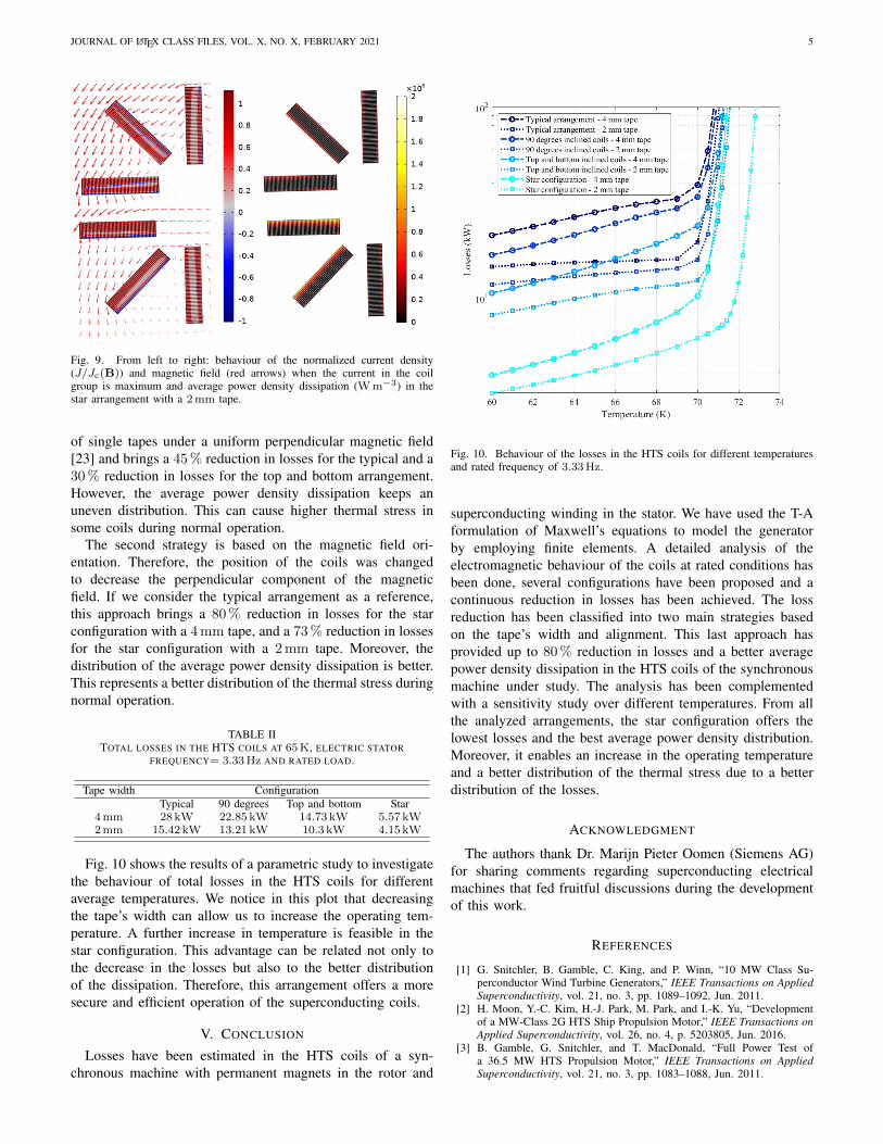
Fig. 10 shows the results of a parametric study to investigatethe behaviour of total losses in the HTS coils for differentaverage temperatures. We notice in this plot that decreasingthe tape’s width can allow us to increase the operating tem-perature. A further increase in temperature is feasible in thestar configuration. This advantage can be related not only tothe decrease in the losses but also to the better distributionof the dissipation. Therefore, this arrangement offers a moresecure and efficient operation of the superconducting coils.
V. CONCLUSION
Losses have been estimated in the HTS coils of a syn-chronous machine with permanent magnets in the rotor and
Fig. 10. Behaviour of the losses in the HTS coils for different temperaturesand rated frequency of 3.33Hz.
superconducting winding in the stator. We have used the T-Aformulation of Maxwell’s equations to model the generatorby employing finite elements. A detailed analysis of theelectromagnetic behaviour of the coils at rated conditions hasbeen done, several configurations have been proposed and acontinuous reduction in losses has been achieved. The lossreduction has been classified into two main strategies basedon the tape’s width and alignment. This last approach hasprovided up to 80% reduction in losses and a better averagepower density dissipation in the HTS coils of the synchronousmachine under study. The analysis has been complementedwith a sensitivity study over different temperatures. From allthe analyzed arrangements, the star configuration offers thelowest losses and the best average power density distribution.Moreover, it enables an increase in the operating temperatureand a better distribution of the thermal stress due to a betterdistribution of the losses.
ACKNOWLEDGMENT
The authors thank Dr. Marijn Pieter Oomen (Siemens AG)for sharing comments regarding superconducting electricalmachines that fed fruitful discussions during the developmentof this work.
REFERENCES
[1] G. Snitchler, B. Gamble, C. King, and P. Winn, “10 MW Class Su-perconductor Wind Turbine Generators,” IEEE Transactions on AppliedSuperconductivity, vol. 21, no. 3, pp. 1089–1092, Jun. 2011.
[2] H. Moon, Y.-C. Kim, H.-J. Park, M. Park, and I.-K. Yu, “Developmentof a MW-Class 2G HTS Ship Propulsion Motor,” IEEE Transactions onApplied Superconductivity, vol. 26, no. 4, p. 5203805, Jun. 2016.
[3] B. Gamble, G. Snitchler, and T. MacDonald, “Full Power Test ofa 36.5 MW HTS Propulsion Motor,” IEEE Transactions on AppliedSuperconductivity, vol. 21, no. 3, pp. 1083–1088, Jun. 2011.

JOURNAL OF LATEX CLASS FILES, VOL. X, NO. X, FEBRUARY 2021 6
[4] K. S. Haran, S. Kalsi, T. Arndt, H. Karmaker, R. Badcock, B. Buck-ley, T. Haugan, M. Izumi, D. Loder, J. W. Bray, P. Masson, andE. W. Stautner, “High power density superconducting rotating ma-chines—development status and technology roadmap,” SuperconductorScience and Technology, vol. 30, no. 12, p. 123002, Nov. 2017.
[5] S. S. Kalsi, Applications of High Temperature Superconductors toElectric Power Equipment. Hoboken, NJ, USA: John Wiley &Sons, Inc., Mar. 2011. [Online]. Available: http://doi.wiley.com/10.1002/9780470877890
[6] A. Abrahamsen, N. Magnusson, B. Jensen, and M. Runde, “LargeSuperconducting Wind Turbine Generators,” Energy Procedia, vol. 24,pp. 60–67, 2012.
[7] S. S. Kalsi, “Superconducting Wind Turbine Generator EmployingMgB2 Windings Both on Rotor and Stator,” IEEE Transactions onApplied Superconductivity, vol. 24, no. 1, p. 5201907, Feb. 2014.
[8] S. Sanz, T. Arlaban, R. Manzanas, M. Tropeano, R. Funke, P. Kovac,Y. Yang, H. Neumann, and B. Mondesert, “Superconducting light gen-erator for large offshore wind turbines,” Journal of Physics: ConferenceSeries, vol. 507, p. 032040, 2014.
[9] D. Liu, H. Polinder, A. B. Abrahamsen, and J. A. Ferreira, “Comparisonof 10 MW superconducting generator topologies for direct-drive windturbines,” in 2015 IEEE International Electric Machines & DrivesConference (IEMDC). Coeur d’Alene, ID: IEEE, May 2015, pp. 174–180.
[10] “EcoSwing project.” [Online]. Available: https://ecoswing.eu/project[11] R. Wesche, Physical Properties of High-TemperatureSuperconductors.
United Kingdom: John Wiley & Sons, Ltd, 2015.[12] M. Zhang, M. Chudy, W. Wang, Y. Chen, Z. Huang, Z. Zhong, W. Yuan,
J. Kvitkovic, S. V. Pamidi, and T. A. Coombs, “AC Loss Estimation ofHTS Armature Windings for Electric Machines,” IEEE Transactions onApplied Superconductivity, vol. 23, no. 3, p. 5900604, Jun. 2013.
[13] Y. Mawatari, “Critical state of periodically arranged superconducting-strip lines in perpendicular fields,” Physical Review B, vol. 54, no. 18,pp. 13 215–13 221, Nov. 1996.
[14] ——, “Critical State in Superconducting Strip-Array Systems withTransport Current,” in Advances in Superconductivity IX. Japan:Springer-Verlag, Oct. 1997, pp. 575–580.
[15] G. P. Mikitik, Y. Mawatari, A. T. S. Wan, and F. Sirois, “AnalyticalMethods and Formulas for Modeling High Temperature Superconduc-tors,” IEEE Transactions on Applied Superconductivity, vol. 23, no. 2,p. 8001920, Apr. 2013.
[16] C. R. Vargas-Llanos, S. Lengsfeld, and F. Grilli, “T-A formulation forthe design and AC loss calculation of a superconducting generator for a10 MW wind turbine,” IEEE Access, vol. 8, pp. 208 767–208 778, Nov.2020.
[17] H. Zhang, M. Zhang, and W. Yuan, “An efficient 3D finite elementmethod model based on the T–A formulation for superconducting coatedconductors,” Superconductor Science and Technology, vol. 30, no. 2, p.024005, Dec. 2016.
[18] F. Liang, S. Venuturumilli, H. Zhang, M. Zhang, J. Kvitkovic, S. Pamidi,Y. Wang, and W. Yuan, “A finite element model for simulating secondgeneration high temperature superconducting coils/stacks with largenumber of turns,” Journal of Applied Physics, vol. 122, no. 4, p. 043903,Jul. 2017.
[19] J. Rhyner, “Magnetic properties and AC-losses of superconductors withpower law current—voltage characteristics,” Physica C, vol. 212, no.3-4, pp. 292–300, Jul. 1993.
[20] Y. Liu, M. Noe, J. Ou, P. Breining, M. Veigel, and M. Doppelbauer,“Measurement of Magnetic Materials at Room and Cryogenic Tempera-ture for Their Application to Superconducting Wind Generators,” IEEETransactions on Applied Superconductivity, vol. 28, no. 3, p. 5206006,Apr. 2018.
[21] D. Hazelton, “Status of 2G HTS Wire for Electric Power Applications,”Apr. 2013. [Online]. Available: http://www.superpower-inc.com/system/files/2013 0426+CIGRE+WG38+Wksp SuperPower.pdf
[22] S. Zou, V. M. R. Zermeno, and F. Grilli, “Simulation of Stacks of High-Temperature Superconducting Coated Conductors Magnetized by PulsedField Magnetization Using Controlled Magnetic Density DistributionCoils,” IEEE Transactions on Applied Superconductivity, vol. 26, no. 3,p. 8200705, Apr. 2016.
[23] E. H. Brandt and M. Indenbom, “Type-II-superconductor strip withcurrent in a perpendicular magnetic field,” Physical Review B, vol. 48,no. 17, pp. 12 893–12 906, Nov. 1993.