journal of machine engineering, 2021 vol. 21 no. 2, 5 23
TRANSCRIPT
Journal of Machine Engineering, 2021, Vol. 21, No. 2, 5–23
ISSN 1895-7595 (Print) ISSN 2391-8071 (Online)
Received: 03 March 2021 / Accepted: 28 April 2021 / Published online: 10 June 2021
drilling process, adaptronic spindle,
qualitative drill holes
Alexander DOBRINSKI1*
Hans-Christian MÖHRING1
Thomas STEHLE1
DEVELOPMENT OF AN ADAPTRONIC SPINDLE FOR A FAULTLESS
MACHINING OF HOMOGENEOUS AND INHOMOGENEOUS MATERIALS
One of the latest topics in construction concerns the difficulty of producing faultless drill holes in parts made
of composite and sandwich materials. At the Institute for Machine Tools of the University of Stuttgart, a prototype
of an adaptronic drilling spindle for a machining of components made of homogeneous and inhomogeneous
materials was developed within the framework of a research project, funded by the Federal Ministry for Economic
Affairs and Energy. The spindle made it possible to limit the axial force and the torque acting on the tool, thus
protecting the tools and the workpieces from any possible damage. The tests carried out with the spindle prototype
proved that the axial feed force acting from the spindle can be reliably controlled by means of the developed
spindle. It might be possible to restrict critical machining situations arising due to the removal of drill chips or
the reduction of process temperatures.
1. INTRODUCTION
One of the latest topics in aircraft and automobile construction concerns the difficulty
of producing qualitative drill holes for riveted and threaded joints in high-quality parts made
of composite materials, materials on a steel or aluminium basis with pore structure as well as
sandwich panels with wave or honeycomb structures. These drill holes have close tolerances
and must not show any microdefects such as tool breakage, scratches or tool marks. In the
drilling of composite materials, different kinds of manufacturing defects can occur, which
may often lead to the failure of valuable workpieces. Approximately 60% of assembly failures
in the aircraft industry are directly connected with damages to the drill hole surface. The most
common defects include delamination, fraying, burrs, a thermally overloaded matrix,
breakaways and fibre tearing [1].
A low thermal conductivity of the matrix causes thermal overloads in the shear zone
between the tool and the drill hole wall during machining. This results in thermal damage,
which leads to the softening and the melting of the matrix and thus to the delamination of the
material.
_____________ 1 Institute for Machine Tools (IfW) at the University of Stuttgart, Germany * E-mail: [email protected]
https://doi.org/10.36897/jme/136277

6 A. Dobrinski et al./Journal of Machine Engineering, 2021, Vol. 21, No. 2, 5–23
As a rule, only air is used as a coolant in CFRP machining. The delamination of CFRP
materials occurs very often during machining and is directly related to the feed force Ff and
tool wear. A delamination damage occurs only when Ff has reached or exceeded a critical
limit. The cutting speed vc is of minor importance here.
Modern manufacturing technology is characterized by a high productivity and
machining precision. This leads to a great wear and stress on the machine tool and cutting
tool, requiring a variety of process monitoring and safety measures [2]. The tool and
workpiece are among the process-relevant objects to be monitored. The aim is to monitor
the current course of the machining process, detect irregular process phenomena and avoid
machining errors. For this purpose, different monitoring systems were developed to monitor
machining processes. These include the intelligent tool holders iTENDO by Schunk and
Coromant Capto Plus, which monitors the machining process directly at the tool and enables
an adaptive real-time control of speed and feed as well as a tool breakage detection through
the use of numerous sensors and complex algorithms, by Sandvik Coromant [3].
To increase the machining quality of components made of composite materials, tool
manufacturers offer a wide variety of drilling and milling tools with defined cutting geometry
made of coated cemented carbide or polycrystalline diamond (PCD). Qualitative CFRP
machining with these tools requires a sharp cutting edge with the smallest possible wedge
angle. However, CFRP materials have a high directionally dependent rigidity, and carbon
fibres are very hard and highly abrasive, which quickly leads to rounded cutting edges during
machining. In the drilling of CFRP, an increasingly rounded cutting edge has a negative effect
on the machining quality since it causes delamination, burrs and fraying in the CFRP
components.
The potential for optimizing the cutting edge geometry of tools with defined geometry
is currently almost exhausted. Therefore, further production possibilities are to be found in
order to cover the increasing manufacturing requirements, especially in the automotive and
aircraft industry. For example, the active adjustment of cutting parameters (ACP) directly
during the cutting process may lead to a significant increase in the effectiveness of the drilling
process and thus an improvement in quality.
Experimental investigations proved that the quality of drill holes is not only determined
by the tool geometry but also by the cutting parameters and that a correct cutting strategy can
have a significant influence on the machining quality [4]. For example, the feed rate or
the axial feed force Ff determine the delamination size of CFRP at the drill exit. The amount
of fraying depends also on the feed force and increases with rising feed values.
The fraying defects are usually distinctive at the entry and exit. Fibre breakage and fibre
tearing lead to a reduction in the mechanical properties, e.g. the fatigue limit, of components
and occur frequently during the machining of aramid fibre reinforced plastics (AFRP). These
defects can be minimized by using circular milling or axial tool movements in drilling. Other
defects include burr formation and breakaways. With growing feed rate, the breakaway at
the entry and exit of the drill hole increases and thermal material damage occurs [5]. As is
generally known, the deformation energy and thus the temperature are mainly within the chip,
which can lead to thermal damage of the CFRP matrix (see above) and to a change in the drill
hole geometry. In the drilling of CFRP, there are also production problems due to the short
life of the cemented carbide tool and the high prices of PCD drills as well as due to the high

A. Dobrinski et al./Journal of Machine Engineering, 2021, Vol. 21, No. 2, 5–23 7
process temperatures and the chip compression in the flutes [6]. The use of hybrid
technologies such as ultrasonically assisted machining leads to an increase in the efficiency
of CFRP drilling as well [7]. It was found out that ultrasonic drilling reduces cutting forces,
torques, the process temperature as well as tool wear and increases machining quality [8, 9].
To investigate the potential of the ACP strategy, a research project was conducted at
the Institute for Machine Tools of the University of Stuttgart in cooperation with Hugo
Reckerth GmbH. This project was funded by the Federal Ministry for Economic Affairs and
Energy via the AiF. Its objective was to develop a prototype of an adaptronic drilling spindle
for a faultless machining of different homogeneous and inhomogeneous materials such as
steel, aluminium, composite materials, glass, cemented carbide, etc. The intention here was
that the spindle to be developed should be able to realize the ACP strategy during
the machining process by controlling the axial feed force Ff acting on the tool during drilling
and by automatically limiting the stress on the tool due to the resistance forces and section
moduli generated in the shear zone. When a predefined axial force or predefined torque is
exceeded, the tool should be shortly withdrawn out of the shear zone. In critical machining
phases, e.g. when the drill enters and especially exits the tool as well as at the junction between
the material boundaries in stacks and laminates, the axial force and the torque should be
adjusted via the control of the linear motor, thus immediately limiting the excessively
increased resistance forces. In the phase of high-efficiency drilling, when the tool cutting edge
is within the workpiece body and the material removal rate is great, the direction of action
of the feed force Ff should be controlled in a pulsed manner so that the chip breakage and
the chip removal can take place effectively, the temperature in the shear zone drops and
the tool cools down. These options can significantly minimize delamination, fraying, burr
formation, thermal damages to workpieces and mechanical failure of tools as well as increase
the geometrical accuracy and surface quality of the manufactured drill holes.
From an application technology point of view, the adaptronic drilling spindle with drive
motor should be mounted on the Z-axis of a drilling or milling machine as an autonomous
machining unit or should be linked to the machine spindle by means of the hollow shaft taper
as a retrofit unit. Hence, the adaptronic drilling spindle with control components should
represent a universal drilling system for the qualitative machining of different materials by
means of with defined and undefined cutting geometry.
2. DESIGN AND DEVELOPMENT OF THE DRILLING SPINDLE
The conducted literature and patent research confirmed the importance of the tasks set
and provided necessary information to define the operating parameters for the adaptronic
drilling system to be developed. The close cooperation between the project partners enabled
a quick definition of the technical parameters relevant for the novel drilling spindle. These
included here the diameters of the drilling tools, the necessary spectrum of spindle speed,
the required quantity of the axial stroke movements of the tool and the suitable motor spindle
variant for the tool drive of the prototype. After the prototype of the adaptronic drilling device
was developed, pilot tests for determining the potential of the ACP strategy were carried out
with it.
8 A. Dobrinski et al./Journal of Machine Engineering, 2021, Vol. 21, No. 2, 5–23
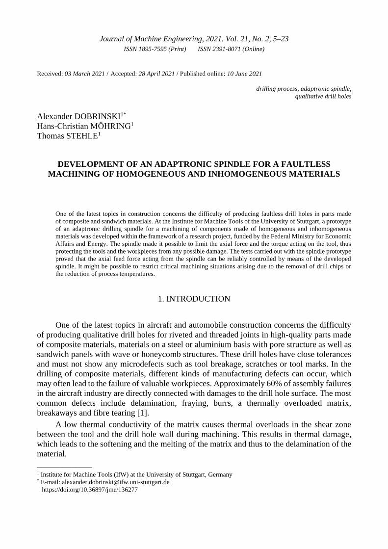
In the development of the adaptronic drilling spindle, the necessary components of the
system were defined first. Several possible concepts of the axial tool drive were compared
with each other. Based on the defined requirements, a concept of the adaptronic spindle was
created. Figure 1 shows its design principle. The knowledge of the stroke length made it
possible to assess the most important parameters of the linear motor. For the axial drive
of the tool, a linear motor was developed which was free of hysteresis and could exert
a controllable axial force Ff on the tool over the entire stroke length. The aim of the first step
was to provide the basis for the design of an experimental linear DC motor.
One of the most important parameters was the axial force Ff generated by the linear
motor. This force Ff was used to confirm the functional capability of the tool and was
established with the following formula:
𝐹𝑓 = 𝐵 ⋅ 𝐼 ⋅ 𝑙
where:
Ff – effective force on the conductor in the magnetic field,
B – magnetic flux density or magnetic induction in the air gap between the coils,
I – current intensity in the stator coil,
l – length of the electric conductor in the stator coil.
Fig. 1. Components of the adaptronic drilling device:
1 - housing, 2 – stator coil, 3 – rotor coil, 4 – magnetic core, 5 – magnetic conductor, 6 – power supply/stator,
7 – power supply/rotor, 8 – force splitter system, 9 – drive motor of the tool

A. Dobrinski et al./Journal of Machine Engineering, 2021, Vol. 21, No. 2, 5–23 9
In order to define the dimensions of the individual components of the linear motor,
a series of tests were carried out with the ANSYS MAXWELL simulation package. The most
important components of the motor were modelled, and the design parameters of the magnetic
current lines and electric coils were adjusted with regard to the generation of the axial force
Ff. The created simulation models are shown in Fig 2. It was investigated here how the axial
force can be influenced by the design of the stator and rotor coils as well as other parameters.
a) dst / dmob (core diameter) b) „Length / height" of the coil c) Examination of the wall
of stator and rotor coils cross-section of the stator coil thickness hmax
Fig. 2. Simulation models for the analyses in ANSYS MAXWELL
In the simulation, the following parameters and correlations were identified:
1. The axial force Ff of the linear motor depended on the ratio of the stator coil’s core
diameter dst to the rotor coil’s core diameter dmob. An optimal value dst / dmob of the core
diameters was defined for the design of the linear motor.
2. The axial force Ff had only a minor dependence on the ratio of the stator coil’s length
Lst to the stator coil’s winding thickness hst.
3. The ratio of the coil length to the winding thickness of the rotor coil had a significant
effect on the axial force Ff. The simulation results showed that there is an optimal ratio
at which the motor generates the greatest axial force Ff (see Fig. 3a).
4. The test showed a strong dependence of the axial force Ff on the wall thickness of the
linear motor housing (see Fig. 3b)
The analysis of the simulation results showed that the geometry of the linear motor
components was relevant for the generated axial force Ff. The following parameters were
particularly important to the design of a functionally capable linear motor: the length and
the width of the stator and rotor coils, wire diameter, wire material, the number of windings,
housing geometry, the distances between the coils and the housing as well as the moving
masses (rotor with drive shaft and tool chuck).
For the development of the linear motor components, the operating temperatures on the
coil surfaces in continuous operation were also taken into account. Therefore, the components

10 A. Dobrinski et al./Journal of Machine Engineering, 2021, Vol. 21, No. 2, 5–23
of the linear motor were manufactured out of thermostable materials. As preliminary tests
with a model of the linear motor showed, the temperature on the coil surfaces must not exceed
80°C. For that reason, the linear motor was equipped with a cooling system.
a)
b)
Fig. 3. Results of the simulations concerning the influence of the geometry parameters of the linear motor on the
generated axial force Ff: a) curve of the axial force Ff for varying ratios of the coil length L_mob to winding thickness
h_mob, b) curve of the axial force Ff for a varying wall thickness hmax
hmax [mm]

A. Dobrinski et al./Journal of Machine Engineering, 2021, Vol. 21, No. 2, 5–23 11
Based on the simulations, a functional model of the linear motor was created. The model
consisted of a housing, a stator with a rigid stator coil and a rotor with the rotor coil, which
could move axially (see Fig. 4). The characteristics of the electromagnetic field of the stator
and the housing were decisive for the working of the linear motor. Therefore, magnetically
soft materials were selected for these components. The model of the linear motor was used to
check the function capability of the linear motor for the designed adaptronic drilling spindle.
The experimental tests of the functional model confirmed the appropriateness of the concept
chosen for the linear motor. When the coils were fed with direct current, magnetic fields were
generated in the stator and rotor coils and induced electrodynamic and electromagnetic forces.
In order to generate the movements of the rotor in both directions, the current value could
only be changed in one coil with a control unit. This influenced the force ratio so that the rotor
was set in motion. The rotor could generate a translatory motion in both directions with
a controlled axial force depending on the current parameter.
Fig. 4. CAD – functional model of the linear motor for the drilling device: 1 – stator body, 2 – stator coil,
3 – rotor coil, 4 – rotor body, 5 – rotor cover, 6 – housing
In the functional model of the linear motor, the value of the fed current I or the voltage
U in the stator coil was controlled. The current value in the rotor coil remained constant here.
Thus the translatory motions of the rotor in the specific direction were generated with
the desired feed force Ff or the axial force FZ. In this way, it was possible to adjust
the permissible axial force FZzul directly during the machining process. An important
advantage of this linear motor was that it is not necessary to change the polarity of the coil
windings to change the direction of the rotor motion. To change the direction of motion, only
the current I in the turns of the stator coil was changed. Such a control system made it possible
to apply the axial force Ff to the tool exactly and without hysteresis during machining. In
addition, the linear motor of the adaptronic spindle was brushless as well as without sparks
and friction, making the motor particularly reliable and explosion-proof. One of the most
important components of the adaptronic drilling spindle was a mechanical force splitter
system, which was used for limiting the maximum torque acting on the drill. The design of
the mechanism was backlash-free and allowed immediate removal of the tool from the drilling
12 A. Dobrinski et al./Journal of Machine Engineering, 2021, Vol. 21, No. 2, 5–23
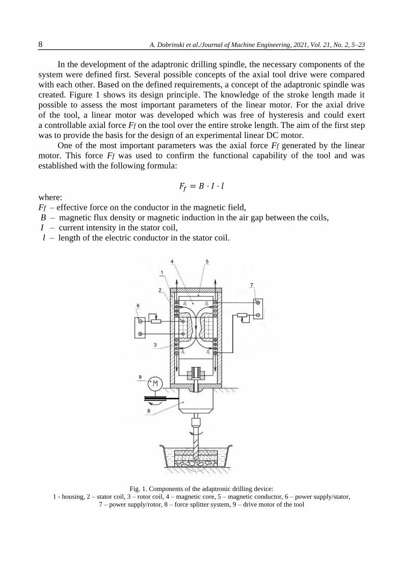
zone when the drilling torque increased. For this purpose, the force splitter performed
a vectorial force decomposition of the axial drilling force Ff and the drilling torque MZ, which
enabled an immediate reduction in force and torque. The effect of this force splitter was based
on the principle of inclined plane. During the drilling process, the force Ff generated by
the linear motor was transmitted as axial force FZ to the workpiece via the tool and the tool
performed the cutting operation with a constant torque MZ (from the force FM) (see Fig. 5).
In this case, the resistance force FZw corresponded to the normal drilling process and
the resulting force FT was directed downwards. When the resistance force FZw or the section
modulus Mw exceeded a predefined value, the resulting force FT was directed upwards so that
the tool moved upwards and out of the shear zone. The resistance force FZw decreased
correspondingly, and the axial force FZ reached the predefined value again. The tool moved
downwards and came into contact with the workpiece again. This option protects tools and
workpieces from breakage or damage, which is particularly common at the drill exit from
sheet metal or when drilling materials on a steel or aluminium basis with pore structure as
well as sandwich materials with wave and honeycomb structures.
Fig. 5. Operating principle of the force splitter
3. ANALYSIS OF CONTROL STRATEGIES FOR THE CONTROL SYSTEM
THE ADAPTRONIC DRILLING SPINDLE
In conventional drilling, the feed rate vf remains constant and the feed force Ff is
the same in all phases of the drilling process, for example, when the tool enters and leaves
the workpiece as well as along the entire length of the drill hole. Experience shows that this
can lead to the damages to workpiece and tool described above. The developed drilling
spindle made it possible to control the feed force Ff or the axial force FZ during the drilling
process depending on the actual tool position and to avoid the above-mentioned damages.
Thus, for example, the axial force FZ could be gradually increased or decreased at an unchan-
ged cutting speed vc, depending on the achieved tool position or drilling depth, which has

A. Dobrinski et al./Journal of Machine Engineering, 2021, Vol. 21, No. 2, 5–23 13
significant advantages for composite materials. In stack machining, the feed force could be
changed depending on the material to be drilled or on the tool position in the drill hole and
could be lowered at the tool exit to avoid drill breakage and burr formation.
The developed control system of the drilling spindle could realize these and other
machining strategies. The drilling strategies could differ depending on the objective, e.g.
a high productivity, a high machining accuracy or a long tool life or rather the prevention
of tool breakage. For each objective, a maximum permissible axial force FZ could be defined
in advance depending on the application and realized by controlling the current parameters in
the coils of the linear motor.
The drilling process with the adaptronic drilling spindle differed significantly from
a conventional drilling process. In the conventional drilling process, the drill is inserted into
the workpiece with the predefined constant feed rate vf and drilling torque MZ or axial drilling
force FZ and these process parameters are not changed until the end of the process. With
the developed drilling spindle it is possible to control the axial drilling force FZ depending on
the axial drill position and the feed rate vf depends on the drilling force. For the case taken
into consideration here, the phases of the process had to be defined before the drilling process.
First, the tool was put into the starting position at the beginning of the drilling process. For
that purpose, only the rotor coil was fed with stabilized direct current, and the rotor coil moved
upwards together with the tool shaft under the influence of the electromagnetic force. In
the next phase, the current in the stator coil was increased up to a particular value, and
the tool moved downwards to the workpiece surface under the influence of the electrodynamic
force Fedyn. The axial feed force Ff had to be minimal here when the tool touches the surface
of the workpiece, so that the tool and the workpiece could not be damaged. Then the current
values in the field coil were raised for spot drilling. The feed force Ff increased, and the tool
began to cut. When the drill point had entered the workpiece completely, the axial force FZ
could reach the maximum permissible limit. Then the phase of effective drilling began.
The tool could carry out the axial motions according to the requirements, the workpiece
thickness and the material properties, e.g. in order to remove the chips out of the drill hole as
well as cool down tool and workpiece. Close to the drill exit, the axial force must be reduced
again. For that purpose, the current values in the stator coil were reduced during the drilling
phase and should be adjusted so that the tool could perform axial motions under the influence
of the force splitter in the case of a possible increase in resistance force and section modulus.
This prevented tool breakage, burr formation and other damaging effects. In order to realize
these options of the adaptronic drilling spindle, a computer-aided control system for the linear
motor was built.
The linear motor was controlled by changing the current parameters only in the turns
of the stator coil. The current values in the rotor coil had to be adjusted in advance and
remained constant during the drilling process. The feed force Ff and the direction of the axial
tool motions were defined by changing the current parameters in the stator coil. The axial
position of the tool in the drill hole should be monitored during the drilling process.
An inductive sensor in the spindle prototype was used for this purpose. When the tool reached
a particular position in the drill hole or nearly broke through the workpiece, the current
intensity IStator in the stator coil must be reduced to ensure a smoother drill exit and thus
prevent e.g. fraying, delamination, burr formation or tool breakage.
14 A. Dobrinski et al./Journal of Machine Engineering, 2021, Vol. 21, No. 2, 5–23
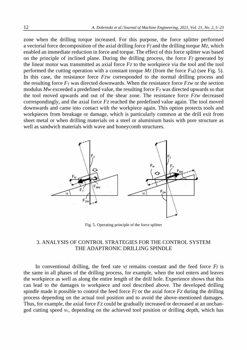
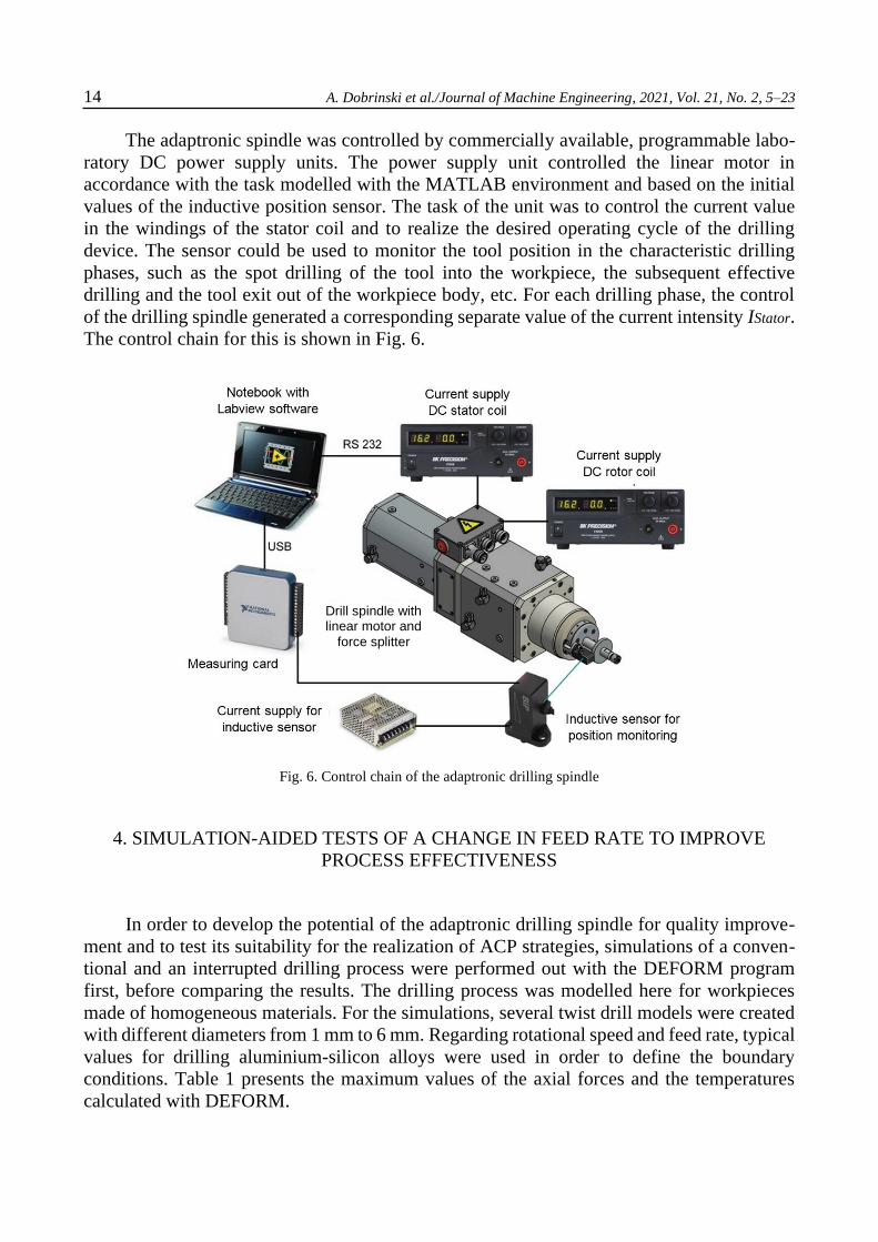
The adaptronic spindle was controlled by commercially available, programmable labo-
ratory DC power supply units. The power supply unit controlled the linear motor in
accordance with the task modelled with the MATLAB environment and based on the initial
values of the inductive position sensor. The task of the unit was to control the current value
in the windings of the stator coil and to realize the desired operating cycle of the drilling
device. The sensor could be used to monitor the tool position in the characteristic drilling
phases, such as the spot drilling of the tool into the workpiece, the subsequent effective
drilling and the tool exit out of the workpiece body, etc. For each drilling phase, the control
of the drilling spindle generated a corresponding separate value of the current intensity IStator.
The control chain for this is shown in Fig. 6.
Fig. 6. Control chain of the adaptronic drilling spindle
4. SIMULATION-AIDED TESTS OF A CHANGE IN FEED RATE TO IMPROVE
PROCESS EFFECTIVENESS
In order to develop the potential of the adaptronic drilling spindle for quality improve-
ment and to test its suitability for the realization of ACP strategies, simulations of a conven-
tional and an interrupted drilling process were performed out with the DEFORM program
first, before comparing the results. The drilling process was modelled here for workpieces
made of homogeneous materials. For the simulations, several twist drill models were created
with different diameters from 1 mm to 6 mm. Regarding rotational speed and feed rate, typical
values for drilling aluminium-silicon alloys were used in order to define the boundary
conditions. Table 1 presents the maximum values of the axial forces and the temperatures
calculated with DEFORM.
Drill spindle with linear motor and
force splitter
A. Dobrinski et al./Journal of Machine Engineering, 2021, Vol. 21, No. 2, 5–23 15
Table 1. Results of the simulations of a conventional drilling process with DEFORM
In addition, the simulation results showed that the temperatures at the cutting edge
increased up to 870°C, thus exceeding the melting limit of aluminium. To avoid this, an active
adjustment of the cutting parameters could be applied. For example, a short with drawing
of the drill by means of an axial tool motion could reduce the cutting temperature during
the drilling process. A temperature reduction is also important when machining CFRP, since
the high cutting temperatures are often above the melting point of the epoxy resin matrix and
thus cause delamination.
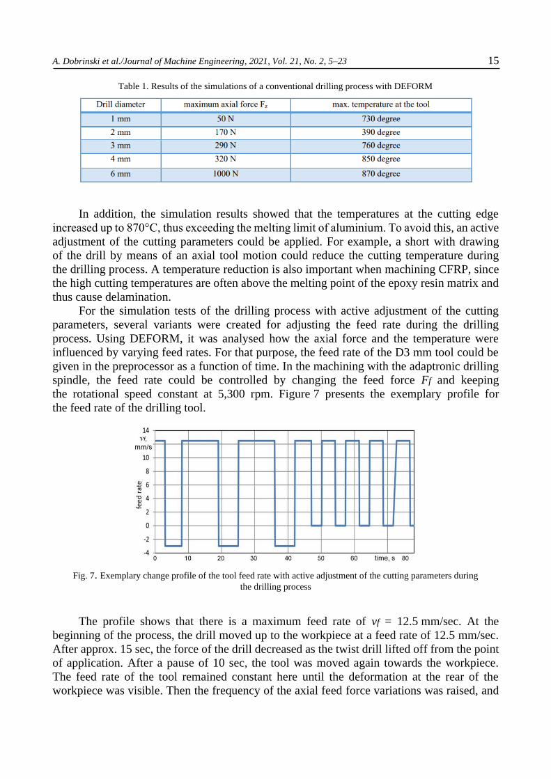
For the simulation tests of the drilling process with active adjustment of the cutting
parameters, several variants were created for adjusting the feed rate during the drilling
process. Using DEFORM, it was analysed how the axial force and the temperature were
influenced by varying feed rates. For that purpose, the feed rate of the D3 mm tool could be
given in the preprocessor as a function of time. In the machining with the adaptronic drilling
spindle, the feed rate could be controlled by changing the feed force Ff and keeping
the rotational speed constant at 5,300 rpm. Figure 7 presents the exemplary profile for
the feed rate of the drilling tool.
Fig. 7. Exemplary change profile of the tool feed rate with active adjustment of the cutting parameters during
the drilling process
The profile shows that there is a maximum feed rate of vf = 12.5 mm/sec. At the
beginning of the process, the drill moved up to the workpiece at a feed rate of 12.5 mm/sec.
After approx. 15 sec, the force of the drill decreased as the twist drill lifted off from the point
of application. After a pause of 10 sec, the tool was moved again towards the workpiece.
The feed rate of the tool remained constant here until the deformation at the rear of the
workpiece was visible. Then the frequency of the axial feed force variations was raised, and

16 A. Dobrinski et al./Journal of Machine Engineering, 2021, Vol. 21, No. 2, 5–23
the amplitude of the axial tool motions was reduced. A reduction of the temperature in the
shear zone was achieved due to the axial tool motions and the short interruptions of the cutting
process.
Using the simulations, it was also examined whether the temperature can be reduced by
changing the axial feed rate vf. The simulation results showed that the temperature of the tool
cutting edge at the drill exit could be significantly decreased by adjusting the feed rate
(see Fig. 8).
Fig. 8. Comparison of temperature changes in conventional drilling and drilling with active adjustment
of cutting parameters
The temperature of the tool rose continuously at constant feed rates. When changing
the feed rate vf, there was a significant reduction in temperature. At negative feed rates, i.e. at
the return stroke of the tool, the temperature reduction was significantly greater because
the drill moved out of the shear zone and the chips were removed out of the drill hole.
The high temperatures at the rim of the cutting edge had a decisive influence on the typical
machining defects in CFRP drilling and were responsible for delamination and melting.
In the temperature diagram, it can be seen that, one the one hand, the temperature during
the negative feed decreases significantly and, on the other hand, the maximum temperature at
an adapted feed rate is approx. 140°C lower compared with the unchanged feed rate. Hence,
the simulation results showed that the feed rate strongly influences the temperature of the
tool. When the feed rate was negative, the drill moved slightly away from the shear zone and
the temperature decreased greatly. In conventional drilling processes, the feed rate was
constantly positive, the axial force FZ remained unchanged and the temperature increased
continuously. The maximum temperature could be reduced by 140°C from 780°C to 640°C
at partially negative feed rates compared with unchanged drilling processes. The temperatures
at the tool point differed on average by about 50°C from the temperatures at the tool edge.
When the feed rate was varied, the drilling process could take longer because the cutting
process was interrupted for a short time and the cutting capacity could be lower. The drilling

A. Dobrinski et al./Journal of Machine Engineering, 2021, Vol. 21, No. 2, 5–23 17
process would take up to 30% longer with a modelled speed profile. Yet such a production
option would involve advantages such as quality assurance, reduction of delamination and
burr formation as well as high process reliability, which are often considerably more
important, especially when machining high-quality components made of CFRP.
5. EXPERIMENTAL SET-UP AND EXAMINATION OF THE LINEAR MOTOR
A universal milling machine was used to carry out the machining tests with
the developed prototype of the adaptronic drilling spindle (see Fig. 9). When engineering and
designing the developed drilling device, it was intended that drilling processes with different
tools, such as HSS and solid carbide drills as well as diamond points with a diameter range
between 1 and 6 mm, could be carried out with it. The power supply of the drilling device
was realized by means of two commercially available laboratory power supply units with
programming function. These power supply units generated the stabilizing direct current and
fed both coils of the linear motor, so that it was possible to control the axial feed force Ff as
well as to axially move the tool shaft in both directions is possible.
The axial force FZ and the torque MZ occurring during the drilling tests were measured
with a dynamometer by Kistler, Type 9273, which was mounted on the worktable of the
milling machine. Two charge amplifiers were connected via the existing outputs of the dyna-
mometer. The values of the axial force FZ and the torque MZ were transmitted via
a shielded Kistler 1677A5 connection cable to the measuring card, where they were processed
and forwarded to the computer. The measuring system is shown in Fig. 10.
The experimental tests of the linear motor were aimed at determining the achievable
values of the axial forces FZ at different axial tool positions as well as the corresponding
values of the direct current in the stator and rotor coils. The temperature on the coil surfaces
was also controlled in the tests. The cooling system of the adaptronic drilling spindle served
for stabilizing the operating temperatures of the motor spindle and the linear motor.
A compact cooling unit was used to cool the drive spindle and the linear motor.
The tests with the prototype linear motor were carried out varying the electric
parameters. The achievable values of the axial force FZ in both directions of motion were
established here depending on the current intensity I and the voltage U of the direct current
in both coils of the linear motor. The force values were measured for different distances
between the two coils of the linear motor in order to determine the achievable axial force at
different stroke positions of the rotor or tool positions.
In addition to the axial force measurements, the temperatures on the coil surfaces were
also controlled. Based on the results obtained, the parameters of both electric coils of the
linear motor were adjusted specifically, including length, width, wall thickness, wire diameter
and wire length. Furthermore, the effective values of the direct current for driving the linear
motor were established here as well.
Figures 11 and 12 illustrate exemplary measurement curves of the axial forces FZ
developed by the linear motor when changing the tool position, the current power in the stator
coil and the current I in the stator coil.

18 A. Dobrinski et al./Journal of Machine Engineering, 2021, Vol. 21, No. 2, 5–23
The conducted tests with the linear motor showed good results. The results and
development experience gained here will be applied to future designs of the linear motor in
subsequent development phases as well as to series designs of the adaptronic drilling spindle.
Fig. 9. Test setup with the prototype of the adaptronic spindle in the IfW test field
Fig. 10. Measuring chain for recording the curves of feed force FZ and torque MZ during drilling: a) Kistler Type 9272
dynamometer, b) Kistler Type 5070A amplifier, c) laptop with NI LabView and cables for
transmitting measurement signals
Fig. 11. Axial force FZ developed by the linear motor when changing the tool position and the current power
in the stator coil

A. Dobrinski et al./Journal of Machine Engineering, 2021, Vol. 21, No. 2, 5–23 19
Fig. 12. Axial force FZ developed by the linear motor when changing the tool position
and in the stator coil of current I
6. EXPERIMENTAL TESTS OF THE SPINDLE PROTOTYPE AND DISCUSSION
OF RESULTS
The experimental tests of the spindle prototype were aimed at examining the functional
capability of the entire design concept. Solid carbide and HSS twist drills according to DIN
338 as well as diamond grinding mounted points D126 and CBN grinding mounted points
B126 with diameters from 1 to 6 mm were used for the tests. The cutting speed vc or the tool
speed n was defined as a function of the respective tool diameter and the type of material.
The pilot tests were carried out with semi-finished products made of different materials (steel,
titan, aluminium, CFRP, GRP, honeycomb, glass, cemented carbide, etc., see Fig. 13).
Fig. 13. Test drilling in semi-finished products made of different materials (CFRP, cemented carbide, glass, GRP)
The values of the maximum permissible drilling force FZ were used for the tools
between 1 to 3 mm from the simulation results with DEFORM. For the tools with diameters
between 4 to 6 mm, the maximum achievable for the spindle prototype FZ-force values were
applied. In serval series of tests, the workpieces were fixed and drilled at angles between 45°

20 A. Dobrinski et al./Journal of Machine Engineering, 2021, Vol. 21, No. 2, 5–23
and 85° to the spindle axis. During the machining tests with the spindle prototype, the FZ
values were varied and adjusted with regard to drilling quality and process stability.
The effective torques and axial forces were established with the built measuring system.
It was found out in the tests that the values of the feed force Ff ranging between “–” 60
N (the tool lifts off the workpiece) and “+” 80 N (the tool penetrates the workpiece) could be
safely changed and reliably controlled in real time via current parameters in the coils
of the linear motor. The drilling process with the developed spindle prototype differed
significantly from a conventional drilling process. In this way, it was possible, for example,
to define and determine the different phases of the drilling process. The axial force FZ could
be reliably controlled within the range from 0 to 80 N along the stroke length of the developed
linear motor during the drilling process (see Fig.14, left). The tool shaft of the drilling spindle
could move axially in both directions to remove the chips and cool the shear zone. By varying
the current values in the stator coil, it was possible to change the parameters of the magnetic
field, which led to a change in the axial force FZ acting on the tool. The “sensitivity” of
the force splitter could be varied by adjusting the specified axial force FZ. This option allowed
the force splitter to work effectively in a wide range of drilling torques. For that reason,
the drilling tools with different diameters were able to perform axial movements even with
a small increase in drilling force or torque above the predefined value, e.g. due to the material
inhomogeneity or chip compression. The task of the force splitter system was to prevent tool
breakage, burr formation and the negative effects of the drill exit. For example, when
machining thin-walled parts made of sheet metal, there is often an effect of screwing-in at
the drill exit, which leads to a sudden increase in the section modulus and axial force.
It can lead to tool breakage and/or damage to the workpiece.
The adaptronic spindle enabled drilling processes even if the workpiece surface is at
an angle of up to 60° to the tool axis of rotation (see Fig. 14, right). The combined effect
of the controlled axial feed force and the force splitter enabled a gentle tool entry on
the workpiece surface. For that purpose, the value of the axial feed force Ff should be 5 to
10 N when the tool touches the workpiece surface. After the drill point entered the workpiece,
the feed force might be increased up to the maximum value without damaging the tool or
the workpiece. It was also found that the gentle tool entry made it possible to easily drill
a thin bridge of approx. 2–3 mm between two adjacent holes without a deviation in the tool
axis and without damaging the tool. This option could also be carried out safely when
the workpiece was inclined. In addition, a series of drilling tests was successfully carried out
with flat and round-shaped glass workpieces by positioning the workpieces perpendicularly
and obliquely to the tool axis (see Fig.13). The adaptronic drilling spindle produced here blind
and through holes faultlessly without glass breakaways and crack formation. Diamond and
CBN tools were used in these tests.
The examinations into the production parameters of the spindle prototype were carried
out to a limited extent and revealed the necessity of further improvements. In order to fully
develop the potential of the adaptronic drilling spindle, further design and control measures
are still to be carried out. These include, for example, the radial stiffness of the bearing of
the axially movable tool shaft, the increase of the axial feed force Ff generated by the linear
motor and the development of a programmable system to control the feed force depending on
the tool position.

A. Dobrinski et al./Journal of Machine Engineering, 2021, Vol. 21, No. 2, 5–23 21
The maximum axial force FZ developed by the linear motor could be up to 100 N
depending on the current value in the motor coils. However, the temperature of the linear
motor increased rapidly at force values over 80 N. Preliminary tests of the prototype showed
that the current values required for a continuous operation in the rotor coil should be up to
5 A. The current values in the stator coil could be varied within the range from 0 to 10 A
in order to enable an efficient control of the axial force FZ.
To remove the chips out of the drill hole and to cool down the tool, the direction
of action of the axial force or rather the direction of movement of the tool shaft could be
changed by controlling the current parameters in the stator coil. This option could also be
used for chip breakage. The experimental tests with the spindle prototype (see Fig. 14)
confirmed the effect and functional capability of the developed force splitter system. Its
design proved to be robust as well as reliable and it could operate in a wide range of rotational
speeds from 0 to 15,000 rpm, effectively limiting the section modulus torque Mw acting
during the drilling process. It can be regarded as further proof of the resolving effect that no
drill was broken in the machining tests carried out with varying tool diameters under different
operating conditions.
Fig. 14. Drilling process with the developed adaptronic spindle: shaft of spindle prototype with collet chuck and drilling
tool as well as sensor of position measuring system at workpiece entry (left) and when drilling inclined
workpieces (right)
The feed force values Ff achieved with the test prototype were reproducible and were
always identical to the corresponding current parameters in the two coils of the linear motor
(see Fig. 15). During the tests, the amount of axial drilling force FZ was controlled by
changing the current parameters in the stator coil via a simple programme. The changes in
drilling force here followed at regular time intervals. If required, the current values and time
intervals could be varied flexibly. Under production conditions, the control of the axial force
FZ depends on the axial tool position, which is recorded via the position sensor. This
possibility has already been realized with a programme in the MATLAB language and is
being tested at the IfW for its practical suitability. The operating temperature at the two coil
surfaces did not exceed the limit of 70°C.

22 A. Dobrinski et al./Journal of Machine Engineering, 2021, Vol. 21, No. 2, 5–23
Fig. 15. Axial force Fz and torque Mz during drilling of the Alu-Si alloy with the programmed control of the current
value in the stator coil (test tool with 3 mm diameter)
Thus a high repetition rate could be guaranteed for the axial force values FZ and torques
MZ during the experiments with the test prototype. Homogeneous aluminium was used as
the workpiece material for the machining tests measuring drilling force FZ and drilling torque
MZ. This allowed the controlled change of the drilling force FZ to be established without
the influence of workpiece-related irregularities.
7. CONCLUSION AND OUTLOOK
After the analysis of possible concepts for the adaptronic drilling spindle, the compo-
nents of the linear motor were developed and produced together with those of the force splitter
system or rather the device for limiting axial force and torque. It was investigated which
characteristics the hysteresis-free linear motor must have for performing feed motions with
a defined axial feed force FZ. With the built prototype of the linear motor or rather
the adaptronic drilling spindle, experimental tests were carried out regarding the achievable
axial forces for varying current parameters in the coils of the linear motor. These tests proved
the functionality of the adaptronic drilling spindle. The force splitter system of the adaptronic
drilling spindle automatically monitored the axial force FZw acting on the tool and the section
modulus Mw during the machining process. When a critical torque value was exceeded,
the drilling spindle briefly lifted the drill and then lowered it to penetrate the workpiece again.
In this way, it was possible to specifically control the feed force and limit the axial force FZ
and the torque MZ acting on the drill. In addition, the developed adaptronic drilling could
prevent the drill from being deflected from the centre of the axis and thus from being centred.
Furthermore, an excessive warming of the component as well as the tool cutting edge and
thus an overheating of the material could be avoided by using the developed drilling spindle.
Hence, the developed drilling spindle enables qualitative and faultless drilling processes
of various materials. In further project steps, the production characteristics of the adaptronic
drilling spindle will be specifically investigated for different materials.
12
10
8
6
4
2
0
–2
12
10
8
6
4
2
0
–2

A. Dobrinski et al./Journal of Machine Engineering, 2021, Vol. 21, No. 2, 5–23 23
ACKNOWLEDGEMENTS
The ZIM project “Development of an adaptronic spindle for the qualitative and faultless drilling of fibre reinforced
plastics and hybrid materials” was funded by the Federal Ministry for Economic Affairs and Energy via the AiF.
The authors would also like to thank the cooperating industry partner for their effective support of this research.
Especially to be mentioned here is the management of Hugo Reckerth GmbH for supporting the design, the production
of components as well as the assembly and the adjustment of the innovative adaptronic drilling spindle.
REFERENCES
[1] PFEIFROTH T., 2014, Beitrag zur Verbesserung der spanenden Bohrbearbeitung von CFK auf Basis von
Schädigungsmechanismen, Dissertation, IfW, Universität Stuttgart.
[2] WECK M., BRECHER C., 2006, Prozessüberwachung, Prozessregelung, Diagnose und Instandhaltungsmaß-
nahmen, Werkzeugmaschinen, 3, VDI-Buch, Springer Vieweg, Berlin, Heidelberg, DOI: 10.1007/978-3-540-325
06-2_6.
[3] mav Innovationsforum März, 2019, www.mav-online.de.
[4] BIERMANN D., RAUTERT C., BATHE T., 2014, Bohrschleifen von CFK mit unterschiedlichen Bindungs-
matrizes, Diamant Hochleistungswerkzeuge, 3, 36–41.
[5] SULTANA I., SHI Z., ATTIA M.H., THOMSON V., 2016, Surface Integrity of Holes Machined by Orbital Drilling
of Composites with Single layer Diamond Tools, Elsevier, Procedia CIRP, 45, 23–26.
[6] BIERMANN D., RAUTERT C., NIEMANN M., BATHE T., 2013, Pecking-Verfahren bietet Potenziale im
Leichtbau, WB Werkstatt + Betrieb, 3, 56–59.
[7] LAUWERS B., 2011, Surface Integrity in Hybrid Machining Processes, Procedia Engineering, 19, 241–251.
[8] FLEISCHER J., TETI R., LANZA G., MATIVENGA P., MÖHRING H.-C., CAGGIANO A., 2018, Composite
Materials Parts Manufacturing, CIRP Annals – Manufacturing Technology, 67/2, 603–626.
[9] LI Y., REN C., WANG H., HU Y., NING F., WANG X., CONG W., 2019, Edge Surface Grinding of CFRP
Composites Using Rotary Ultrasonic Machining: Comparison of Two Machining Methods, The Int. Journal
of Advanced Manufacturing Technology, 100, 3237–3248.