journal of materials chemistry a - gch.ulaval.ca représentatifs... · recent advances in the...
TRANSCRIPT

Journal ofMaterials Chemistry A
REVIEW
Publ
ishe
d on
24
July
201
5. D
ownl
oade
d by
Uni
vers
ité L
aval
on
01/0
9/20
15 1
4:01
:12.
View Article OnlineView Journal | View Issue
Recent advances
ChCUiHPCPfsfd
Department of Chemical Engineering, Lava
E-mail: [email protected]; Fax: +1
Cite this: J. Mater. Chem. A, 2015, 3,18345
Received 14th June 2015Accepted 24th July 2015
DOI: 10.1039/c5ta04326c
www.rsc.org/MaterialsA
This journal is © The Royal Society of C
in the development of sunlight-driven hollow structure photocatalysts and theirapplications
Chinh Chien Nguyen, Nhu Nang Vu and Trong-On Do*
The over-exploitation of fossil fuels means that research into alternative sustainable energy sources is
crucial for the scientific community. The harvesting of solar energy via photocatalysis is a key approach
to developing these alternatives. Furthermore, photocatalytic materials show great promise for
degradation of pollutants. However, limitations in incident light utilization and charge separation are
major drawbacks that restrict the activity of current artificial photosystems. Construction of hollow
nano-sized photocatalysts is emerging as a promising approach to fabricating novel and effective
materials, as hollow photocatalysts possess unique properties that may be exploited to overcome these
challenges. This review gives a concise overview of the advantages of hollow structures for this purpose,
the methodology used to prepare hollow photocatalysts, and the current state-of-the-art in the
development of hollow structure photocatalysts for energy production and environmental applications.
1. Introduction
Global energy demand continues to increase due to populationgrowth and economic expansion. Worldwide energy consump-tion reached 15 terawatts (TW) in 2010 and is expected to nearlydouble itself by 2050. Consequently, global energy shortagesand the environmental damage caused by the combustion offossil fuels will be huge challenges facing civilization over thenext few decades. Research and development of renewable,clean, and carbon-neutral alternative energy resources is, thus,urgently required to reduce our dependence on fossil fuels.
hinh-Chien Nguyen obtainedis BSc and MSc degrees inhemistry Department at Hueniversity of Sciences Viet Namn 2009 and 2011, respectively.e is currently working for hishD degree at Laval University,anada under the supervision ofrof. Trong-On Do. His researchocuses on the development ofunlight-driven photocatalystsor water splitting and air/wateregradation.
l University, Quebec, G1V 0A8, Canada.
-418-656-5993; Tel: +1-418-656-3774
hemistry 2015
Among the renewable energy resources, solar energy is themost abundant. Moreover, solar light, being free and green, isan ideal energy source for overcoming current environmentalchallenges. Considering that, in a single hour, the sun deliversenergy sufficient for all human activities on the planet for anentire year, the harvesting of sunlight by articial photo-catalysts, and it's conversion into solar fuels, is both viable andhighly attractive.
Since Fujishima and Honda rst reported the generation ofH2 through the photoelectrochemical splitting of water on TiO2
electrodes under ultraviolet (UV) light in the early 1970s, theconversion of solar light to chemical energy using semi-conductors has been explored as a key solution for energyproduction and pollutant degradation. However, a major
Nhu-Nang Vu obtained his BScin Chemistry Department at HaNoi University of Sciences VietNam in 2014. He is currentlyworking for his Master degree atLaval University, Canada underthe supervision of Prof. Trong-On Do. He focuses on the devel-opment of perovskite basedphotocatalysts for overall watersplitting via solar energy.
J. Mater. Chem. A, 2015, 3, 18345–18359 | 18345

Journal of Materials Chemistry A Review
Publ
ishe
d on
24
July
201
5. D
ownl
oade
d by
Uni
vers
ité L
aval
on
01/0
9/20
15 1
4:01
:12.
View Article Online
challenge lies in designing an efficient sunlight-driven photo-catalyst system.1
Solar fuels can take the form of hydrogen and hydrocarbonssuch as methane and methanol. These products, which areconsidered as next-generation energy carriers, may be formedby photocatalytic water splitting and by photoreduction of CO2
with water, respectively. Also, the photocatalytic process allowsdirect use of sunlight to decompose a wide range of organicpollutants, as photocatalysts can be excited by light to generateelectron–hole pairs which can drive a variety of redox reactions.2
Much effort has been focused on the development ofsunlight-driven photocatalysts in recent years; however, thesematerials still suffer from two fundamental efficiency bottle-necks: weak photon absorption and poor electron–hole pairseparation. The development of highly efficient photocatalyststhat absorb a large amount of solar energy and exhibit highcharge separation is a key requirement for the conversion ofsolar radiation into chemical bond energy. Such a system couldhave a revolutionary impact on supplying our energy needs in asustainable manner.
Recently, photocatalysts based on semiconductors with ahollow structure have received increasing research attentionbecause of their unusual properties, such as high specicsurface area, large sunlight absorption, and high electron–holeseparation. Furthermore, hollow spheres allow multiple reec-tions of light within the interior cavity, which enhances theeffectiveness of light utilization.
This review summarizes recent progress in the developmentof a variety of routes for the preparation of hollow structurephotocatalysts, and highlights their application to fuelproduction and the decomposition of pollutants. We conclude
Trong-On Do is a full professor inthe Department of ChemicalEngineering at Laval University,Canada. He received his MSc in1986 and PhD in 1989 atUniversity of P. and M. Curie(Paris 6, France). Aer a period atBrunel University (UK) and theFrench Catalysis Institute(France), he moved to LavalUniversity in 1990. He then spenttwo years 1997–1999 in Profs.Hashimoto/Fujishima's group at
Kanagawa Academy of Science and Technology under the JapaneseSTA Fellowship Award before joining again Laval University as aprofessor associated with the NSERC Industrial chair. Trong-OnDo's research is focused on the design and synthesis of innovativeand smart materials and their applications in heterogeneous pho-tocatalysis and renewable energy. He is also a major contributor inthe eld of zeolite-based materials including controlled-size nano-zeolites and hybrid zeolite/mesoporous molecular sieve materials.He has published over 120 papers and review articles in refereedjournals and holds 5 international patents. He is the recipient of the2014 Canadian Catalysis Lectureship Award (CCLA).
18346 | J. Mater. Chem. A, 2015, 3, 18345–18359
with a concise overview of the current status, potential, andfuture development of hollow structure materials with a viewtoward improved performance in different photocatalytic redoxapplications.
2. Basic concept and current status insemiconductor photocatalysts2.1. Concept of photocatalysis based on semiconductors
A photocatalytic system based on a semiconductor can bedescribed by the band gap model, in which the valence band(VB), the highest occupied band, and the conduction band (CB),the lowest empty band, are separated by a band gap, a region offorbidden energies in a perfect crystal. An electron is excited tothe CB and leaves a hole (h+) in the VB when the incident energyis equal to or larger than the band gap of the semiconductor, asdepicted in Fig. 1. The photoexcitation electron becomes uti-lised in a reduction reaction with an electron acceptor; forexample, the reduction of protons to hydrogen, generation of anO2c radical, or CO2 reduction, but only if the CB minimum islocated at a more negative potential than the electrochemicalpotential of the desired reaction. In the VB of the semi-conductor, the photo-generated hole can also perform anoxidative reaction with an electron donor with oxidationpotentials more negative than the VB maximum. Thus, thesemiconductor is the most essential component in systemsintended for the production of green fuel and other environ-mental applications.3
Photocatalysis occurs in the semiconductor via multiplesteps, as illustrated in Fig. 2. When the semiconductor is illu-minated by a light source with higher energy than the band gap,an electron is excited to the CB, leaving behind a hole (Fig. 2(1)).Then, the thus-produced charge carriers migrate to the photo-catalyst surface (Fig. 2(2)). The electron and hole recombine onthe surface or in the bulk material while diffusing to the pho-tocatalytic surface within a few nanoseconds (Fig. 2(3)). Simul-taneously, the charge carriers that reach the semiconductorsurface participate in the chemical conversion of the adsorbedreactants (Fig. 2(4)).4 Therefore, it is widely accepted that greaterthe number of photo-generated carriers that are generated andreach the surface, the more efficiently the photoactive materialwill perform, and thus, photocatalytic performance is signi-cantly inuenced by the incident light absorption ability and
Fig. 1 Electron hole generation under illumination in an inorganicphotosystem; (A) electron acceptor; (D) electron donor.
This journal is © The Royal Society of Chemistry 2015

Fig. 2 General processes in a semiconductor photocatalyst: (1) bandgap excitation; (2) charge diffusion; (3) charge recombination; (4)chemical conversion.
Review Journal of Materials Chemistry A
Publ
ishe
d on
24
July
201
5. D
ownl
oade
d by
Uni
vers
ité L
aval
on
01/0
9/20
15 1
4:01
:12.
View Article Online
charge separation efficiency of the catalyst. Particularly, a pho-tocatalyst that exhibits a band gap around or larger than 3 eVwill show restricted performance in the UV-region, as less than5% of sunlight can be harvested by materials with a 3 eV bandgap. Therefore, it should be noted that the number of electron–hole pairs generated is greater if the light absorption of semi-conductor expands to the long wavelength region, i.e., a pho-tocatalyst working under visible light will produce a higherquantity of photo-induced carriers in comparison with oneirradiated by UV light.
In addition, the structure of the photosystem that utilizes theincident light is also an important factor in generating chargecarriers effectively. For instance, nanotube structures reducelight loss due to the photon being trapped inside the structureby multiple light reections with the wall. The number ofphotogenerated charge carriers, therefore, is signicantlyenhanced in comparison with the conventional morphology.5,6
The second factor that has a strong inuence on photoactivity isthe number of the charge carriers reaching the surface to takepart in chemical conversion. Recombination is oen caused bya scavenger or crystalline defects which can trap the electron orthe hole. Unfortunately, the vast majority of charge carriersproduced recombine immediately aer the band gap excitationevent.7 Based on the fundamental principles of semiconductorphotocatalysis, an efficient photocatalyst must satisfy the lightabsorption and charge separation criteria simultaneously inorder to exhibit high photoactivity.
2.2. Current advances in semiconductor photocatalysis
Light absorption ability and charge carrier separation arearguably the primary areas that need development in photo-catalysis, and much research concerned with furthering thisdevelopment has been recently reported. Band gap engineering,using nano-sized materials and utilization of nanocompositesare the major approaches to improving photocatalysts.
Electronic band structure is the key to solar chemicalconversions. Doping is a method commonly used to extend thelight absorption of wide band gap semiconductors to the
This journal is © The Royal Society of Chemistry 2015
longer-wavelength region. An absorption shi toward the redregion is easy to realise in most doped semiconductors.8 Thedopants can introduce localized electronic states, such as adonor level above the VB or an acceptor level below the CB in theforbidden band of wide band gap photocatalysts, which cannarrow their band gaps. However, it is worth noting that thedopants may or may not cause enhancement to photocatalyticperformance, depending on the doping-induced change in theelectronic band structure, as doped element(s) can function ascharge recombination sites and reduce photoactivity.9 Designand morphological control of the crystal facets of semi-conductor photocatalysts with highly exposed active planes hasbeen proved to be useful for the development of an efficientmaterial.10 Employing different facets with different surfaceatomic structures can narrow the band structure, as well asdrive the photogenerated electron–hole pair in two distinctdirections, leading to enhanced charge separation.11,12 Analternative approach using solid solution photocatalysts hasemerged as a viable solution for the production of effectivematerials. GaN:ZnO, for instance, has shown potential forapplication in overall water splitting that originates from thestrong visible light absorption, despite the wide band gap ofboth GaN (3.4 eV) and ZnO (3.2 eV). Recently, surface modi-cation has attracted increasing attention. Mao et al. rstproposed the synthesis of black TiO2 which showed a highactivity for hydrogen generation by hydrogenation under a 20bar H2 atmosphere for 5 days.13 It is thought that surfacedisorder and oxygen vacancy are the main reasons for the strongvisible/near infra-red light absorption. However, the oxygenvacancies in many cases have proven to jeopardize the photo-catalytic performance as they can act as recombination sites.9,14
In nano-sized materials, the smaller particle size exposesmore active sites as well as lowering the travel path of the chargecarrier to the surface. Quantum dots of metal chalcogens, suchas CdS, CdSe, CdTe, and CuInS2, have already attracted a greatattention due to their unique optical and electronic properties.Photogeneration of electron–hole pairs and their subsequentsplit into free carriers are the two key elements that directlydetermine the light response efficiency of a quantum dotmaterial. However, it is not always accurate that the smaller theparticle size, the higher the efficiency. A strong quantumconnement effect appears to increase the recombinationprobability of photogenerated electron–hole pairs. Although,small particle sizes indicate that charge carriers travelling to thesurface have favourably short distances, this process requires asuitable concentration gradient or potential gradient (internalelectric eld) from the core of the particle to the surface, whichhas a close association with the morphology, structure andsurface properties of nanostructured materials. In other wordsthe internal electric eld that helps separate electron–hole pairsin nanoscale photocatalysts is not sufficient to drive chargecarriers in different directions and therefore leads to increasedcharge recombination.4,15
Recently, the development of hybrid nanostructured photo-catalysts has been shown to be the most efficient method toseparate charge carriers and improve light absorption. A largenumber of excellent reviews have been published on the
J. Mater. Chem. A, 2015, 3, 18345–18359 | 18347

Journal of Materials Chemistry A Review
Publ
ishe
d on
24
July
201
5. D
ownl
oade
d by
Uni
vers
ité L
aval
on
01/0
9/20
15 1
4:01
:12.
View Article Online
progress of composite photocatalysts that readers can refer formore detailed information.16–27 In general, the development ofphoto composites can be categorized into three primaryapproaches: co-catalysts, plasmonic photocatalysts, and het-erojunction structures, as shown in Fig. 3.
A co-catalyst is a component that can only work together witha photocatalyst semiconductor. It is worth noting that co-cata-lysts play two main roles in the enhancement of photocatalyticperformance: they promote charge separation and serve asreaction sites. Upon light irradiation, electrons migrate to thereduction sites to promote the reduction reaction, while thehole migrates to the oxidation co-catalyst to take part in theoxidation reaction, suppressing recombination and signi-cantly enhancing the photoactivity, as shown in Fig. 3A.28 Noblemetals are used as the reduction co-catalyst.29 The differentproperties of the noble metal and n-type semiconductor cause abarrier (Schottky barrier) and space charge region (also calledthe depletion layer) as a result of the electron transfer processfrom the semiconductor near the metal–semiconductor inter-face to the metal when they come into contact. Moreover, thecharge redistribution creates an internal electric eld whichdrives the photogenerated electron and hole to the bulk semi-conductor and metal, respectively. Under the successivephotoexcitation of the semiconductor, a large number of elec-trons accumulate in the semiconductor, making them hotenough to transfer to the metal. Using noble metal-free co-catalysts has also received much attention over recent years.Inexpensive and abundant nano-sized materials formed fromtransition metals (Ni, Co, Cu) and transition metal compounds,such as transition metal oxides, metal hydroxides, and metalsuldes, have been shown to be efficient co-catalysts forreduction reactions. These co-catalysts show activities compa-rable to that of Pt, which is attributed to the effective chargeseparation caused by efficient electron transfer from the semi-conductor to the co-catalyst.30,31 Moreover, carbonaceousnanomaterials, such as carbon nanotubes and graphene, havebeen shown to promote charge carrier separation. Because of
Fig. 3 Typical example of the current developments in photo-composite materials; (A) two separated co-catalysts; (B) plasmonicphotocatalysts; (C) a type II photo composites; (D) an all solid Z-scheme photocatalyst.
18348 | J. Mater. Chem. A, 2015, 3, 18345–18359
their high electrical conductivity, which is caused by sp2-hybrided carbon atoms, they can function as a co-catalyst thataccepts photogenerated electrons from the semiconductorphotocatalyst, leading to signicantly enhanced charge sepa-ration.32–34 In the same manner, photogenerated holes are alsoattracted by oxidation co-catalysts to enhance the oxidationreaction. To extract the holes, their band levels should be higherthan that of the light-harvesting semiconductor. Generally,metal oxides like MnOx, FeOx, CoOx, NiOx, CuOx, RuO2 and IrO2
are selected for oxidation co-catalysts.35 Very recently, carbonquantum dots, a novel class of carbon nanomaterials, have beenshown to promote the rate of water oxidation in the decompo-sition of pure water under solar light. Because of their uniquephoto-induced electron transfer, photoluminescence, andelectron reservoir properties, photocatalyst-based carbonquantum dots not only facilitate charge separation, but are alsopromising as efficient and full sunlight absorptionmaterials.36,37
Localized surface plasmon resonance (LSPR) has beenapplied in the photocatalytic eld and has attracted consider-able attention over the past few years. The presence of plasmonmetal nanoparticles shis the light absorption to the longwavelength region, caused by free electron oscillation on themetal particle surface when the frequency of photons matchesthe natural frequency of these electrons. Through the LSPRexcitation of plasmonic metals, energetic electrons are producedat the metal surface. These energetic electrons remain in theexcited “hot” state for up to 0.5–1 ps; they gain enough energyunder visible light illumination to facilitate the transfer to theconduction band of semiconductor and participate in thechemical conversion, as shown in Fig. 3B. Cu, Ag, and Aunanoparticles generally reveal a strong photoabsorption ofvisible light because their surface plasmon exhibits the absor-bance at approx. 580, 400 and 530 nm, respectively. However,nanostructured copper and silver are easily oxidized, whereas Aunanoparticles display the chemical stability. Furthermore, it isnoted that the photocatalytic performance of plasmonic photo-catalysts is inuenced by many factors such as the nanoparticlesize, the shape and the surrounding environment.35,38
Fig. 3C and D show the typical semiconductor alignment incomposite materials that have been shown to cause a remark-able improvement in photoactivity. Not only is light absorptionimproved in the composite photosystem, but also the electron–hole separation, which is enhanced by electron and holetransfer at the semiconductor–semiconductor junction (type IIsemiconductor) or semiconductor–conductor–semiconductor(all solid Z-scheme).35 In type II semiconductors, the hole–electron separation highly depends on the electric eld at theinterface. In the other words, the strong internal electric eldpromotes efficient charge separation. However, the redox abilityof the charge carriers usually decreases aer the charge transferprocesses. The Z-scheme is proposed to address the problemthrough mimicking the natural photosynthesis system. Thus,using the Z-scheme has some advantages, such as maintainingcharge carrier energy levels and harvesting visible-light toarchive the overall reaction. For example, an all solid Z-schemehas been developed by inserting the conductor between two
This journal is © The Royal Society of Chemistry 2015

Review Journal of Materials Chemistry A
Publ
ishe
d on
24
July
201
5. D
ownl
oade
d by
Uni
vers
ité L
aval
on
01/0
9/20
15 1
4:01
:12.
View Article Online
semiconductors to form ohmic contact with low contact resis-tance. As a consequence, electrons from the CB of semi-conductor A can directly recombine with holes fromsemiconductor B (see Fig. 3D).35
Fig. 4 Schematic illustration of the formation the hollow structure; (A)template strategy; (B) Ostwald ripening;44 (C) Kirkendall effect;45 (D) ionexchange.
3. Hollow structure materials3.1. Advantages of hollow structure photocatalytic materials
The emergence of hollow structure materials has provided anew opportunity to design high-power materials for diverseapplications such as batteries, biomaterials, and heterogeneouscatalysts. Hollow structures possess unique properties. Forexample, the large fraction of empty space in hollow structureshas been used to load and control photocatalytic systems forparticular materials, such as genes, peptides, and biologicalmolecules. Their structural features and connection conduc-tivity reduce the diffusion distance of the electrolyte, andtherefore enhance their suitability as energy storage materials.In addition, hollow catalytic materials have a higher surfacearea, which is a valuable property for heterogeneous catalysts.39
In the photocatalytic eld, hollow structures are a goodchoice for morphology construction in articial photosystems.Firstly, hollow photocatalysts are composed of nanoparticles,and therefore exhibit signicantly improved charge separation.It is worth noting that reducing the particle size to nanoscalehas considerable inuence on electron–hole pair separationdue to the large surface area, lower travel path, and the highdensity of active sites. However, the small space in the nano-sizeparticles enables the photo-generated charge carriers to moreeasily recombine. Hence, the development of photocatalystsshould exploit the advantages of nanoscale materials whilelimiting their negative aspects. Structural forms that combinemicro-scale and nano-sized powdered catalysts are a potentialway to meet both requirements.15,40 Furthermore, hollowstructures exhibit porosity, which reduces the diffusion lengthand improves the accessibility of active sites by the reactants.41
Additionally, the multiple reections within the hollow cavityenhance efficient use of the light source, leading to theproduction of more photogenerated charge carriers.42,43
Consequently, hollow photocatalysts may overcome the currentchallenges associated with light adsorption and charge sepa-ration in the development of photocatalytic semiconductors.
3.2. General strategies for constructing hollow structurephotocatalysts
The formation of hollow materials is based on two mainapproaches: templated and template-free. Fig. 4A shows aschematic illustration of hollow structure formation based on ahard support. The desired material is coated onto the sacricialcore prior to removal of the core by chemical etching or thermaltreatment. Interaction between the precursors and the sup-ported surface prompts the loading of precursors onto the coresurface. Then, the hollow structure is generated aer removal ofthe core.
Polymers, silica, and carbon colloidal spheres are commonlyemployed to construct hollow photocatalysts because their
This journal is © The Royal Society of Chemistry 2015
negative surface charge facilitates interaction between the coreand precursors through electrostatic forces. In the case of SiO2
spheres, the hollow spheres are released aer removing the SiO2
core by chemical etching with NaOH, HF, or NH4HF2, whilethermal treatment is used to obtain the hollow material whenpolymer or carbon spheres are employed as the template.
By contrast, template-free synthesis relies on the physicaland/or chemical properties of the material during the synthesisprocesses. Ostwald ripening, Kirkendall effect, and ionexchange, are the prevailing strategies used to obtain hollowstructures, as depicted in Fig. 4B and C.
In principle, Ostwald ripening can be thought of as theconsequence of a single phase system being put into a two-phase metastable state. The inner phase that has higher energywill move to the stable outer surface through ripening, resultingin the hollow structure.44
As an alternative method, Smigelkas and Kirkendalldemonstrated the movement of an interface between a diffu-sion couple as a result of the different diffusion rates of the twospecies at an increased temperature. This phenomenon, nowdened as the Kirkendall effect, is proposed to explain the voidformation in metal oxide hollow structures. At the highertemperature, if the outward diffusion rate is faster than that ofinward, an internal space will be formed.45 In another method, ahollow material can be obtained through ionic exchange reac-tions due to differences of solubility product constants anddiffusion rate as depicted in Fig. 4D.46 The formation of hollowmetal suldes can usually be explained by this phenomenon.
The works above indicates that diverse hollow structures canbe produced based on hard template and/or template-freestrategies. Utilization of a sacricial core can facilitate theconstruction of materials with uniform morphology, hollowdimensions, and wall thickness. However, core removal bychemical etching or thermal treatment is a disadvantage of thismethod because the phase structure or surface properties canbe impacted by high temperature and chemical reactions. Incontrast, the evolution of hollow materials through template-free approaches preserves surface properties. Additionally, the
J. Mater. Chem. A, 2015, 3, 18345–18359 | 18349
Journal of Materials Chemistry A Review
Publ
ishe
d on
24
July
201
5. D
ownl
oade
d by
Uni
vers
ité L
aval
on
01/0
9/20
15 1
4:01
:12.
View Article Online
hollow dimensions can be controlled by the fabrication condi-tions. However, the conditions suitable for obtaining the hollowstructure, and the non-uniformity of the as-prepared hollowstructures, limit the development of semiconductors based ontemplate-free routes. Therefore, the selection of a suitableapproach to designing hollow structure photocatalysts greatlydepends on the desired photocatalysts and used precursors.
4. State-of-the-art in thedevelopment of hollow photocatalysts
There have been many advances in hollow photocatalystsrecently, and the development of this type of construction cangenerally be divided into two approaches: single componentand composite hollow photocatalysts. The former route hasbeen intensively studied over the last ten years, and has twomain branches: single-shell and multiple-shell hollow struc-tures. However, the composite approach has recently receivedincreasing attention.
4.1. Single-component hollow photocatalysts
4.1.1. Single-shell photocatalysts. Single-shell hollow pho-tocatalysts are the most well-known hollow structure. Theirunusual architecture and simple fabrication method makethem potential candidates for robust photocatalysts. In general,two routes are accepted for the development of hollow photo-catalytic material: hard template and template-free, as dis-cussed above. In the template approach, silica, carbon colloids,and polymer spheres are typical templates for hollow synthesis.The template-free route is based on physical phenomena, suchas Ostwald ripening, the Kirkendall effect, and ionic exchange,as listed in Table 1. Since single-shell photocatalysts have beenshowed the signicant improvement in the photoreactions,below we will therefore select several well-designed nano-structured hollow material as examples.
For instance, Sun et al. reported g-C3N4 hollow sphere pho-tocatalysts for hydrogen production under visible illuminationwith an apparent quantum yield (AQY) of approximately 7.5% at420.5 nm. g-C3N4 was prepared from cyanamide, which wasloaded into silica spheres containing meso pores as the hardtemplate, as described in Fig. 5. The resulting hollow g-C3N4 isformed aer removing the silica core by chemical etching.According to the literature, the hollow spheres showed aremarkable enhancement of photoabsorption in the 440–550nm range, which was attributed to multiple reections withinthe hollow structure. Moreover, it is worth noting that thenumber of defects decreases with the shell thickness to thenano range. For these reasons, the amount of hydrogen gener-ated in the g-C3N4 hollow structure was much higher than thatof bulk g-C3N4 by a factor of 25. Furthermore, the catalystshowed high stability over seven cycles.47 It can be said thatcyanamide and silica nanospheres are good choices for thedesign of the C3N4 hollow structure due to two main reasons:rstly, silica spheres are a thermally stable hard template.Hence, development of the porous structure on the surface ofsilica spheres is feasible. On the other hand, cyanamide
18350 | J. Mater. Chem. A, 2015, 3, 18345–18359
possesses the low melting temperature (44 �C), which promotesloading of this precursor into the porous structure, leading tothe formation of bulk C3N4 through thermal treatment. As aresult, the hollow structure is released aer core removal. Analternative sacricial support strategy is the utilization ofpolymer spheres. This type of support offers uniformmorphology, a simple fabrication method, and ease of surfacemodication. Using this methodology the hollow photocatalystcan be generated by coating with a layer of photocatalyst orprecursor before removing the polymer core. Gao reported thefabrication of Ta3N5 hollow microspheres based on poly(styrene-co-acrylamide) (PSAM) colloidal spheres as a sacricialsupport (Fig. 6). Because of the covalent bond formationbetween Ta(OEt)5 and the amine-functionalized polymer, theTa2O5 precursor is easily loaded onto the template. The hollowstructure of Ta3N5 is formed under nitridation conditions inNH3 at high temperature, producing a material with a highspecic surface area and high volume. By the combination ofmany unique properties, such as their meso-microporousstructure, Ta3N5 hollow microspheres exhibit photoactivityimprovement in the degradation of pollutants.48
Employing carbon colloidal spheres as a sacricial supporthas also received considerable attention for hollow structurepreparation over the last decade. Due to the robust electrostaticinteraction between metal cations and the negative charge onthe carbonaceous sphere surface, high-density absorption ofcation species occurs, followed by the release of the hollowstructure by removing the carbon core through calcination.Also, the hollow photocatalyst can also be produced by one-potsynthesis approach, in which a mixture of metal salt and carbonsphere precursors are put in a sealed autoclave at a precisetemperature. The hollow spheres are then produced by calci-nation to remove the carbon material. Thereby, the develop-ment of carbon colloidal spheres led to a signicant surge in thedevelopment of metal oxide hollow photocatalysts.49
For example, Li et al. reported a GaN:ZnO hollow photo-catalyst constructed on carbon colloidal spheres for hydrogengeneration (Fig. 7). In this preparation, a mixture of Ga3+ andZn2+ is adsorbed onto a carbon colloidal sphere surface inDMF solvent. Mixed oxide GaN:ZnO hollow spheres wereobtained by calcination to combust the carbon core, followedby nitridation in ammonia. It should be noted that the nitri-dation temperature required decreased signicantly due tothe higher surface energy and short atomic diffusion distancein the hollow structure. Furthermore, the as-prepared mate-rial also showed a high surface area (up to 114.4 m2 g�1)attributed to the small grain size (5–10 nm) of GaN:ZnO con-structed on the hollow structure. As a consequence, theGaN:ZnO hollow photocatalyst showed excellent photoactivityin hydrogen generation with a quantum yield (QY) of 17% at400 nm illumination.50 Employing carbon colloidal spheresusually produces high surface photocatalysts due to poresbeing formed during the combustion of the carbon core. Inaddition, the simple preparation route and low cost of carbonsphere precursors (usually glucose or sucrose) have made thismethod very popular for the synthesis of hollow metal oxidestructures.
This journal is © The Royal Society of Chemistry 2015

Table 1 List of single shell hollow photocatalysts
Type Morphology Strategy Application Ref.
TiO2 Hard template – SiO2 spheres RhB degradation 51
TiO2 Template-free – Ostwald ripening Phenol degradation 42
ZnO Hard template – carbon colloidal spheres Degradation of RbB 52
ZnO Template-free – Ostwald ripening Degradation of organic dye 53
Bi2WO6 Template-free – Ostwald ripening Degradation of RhB 54
Bi2WO6 Anion exchange Reduction of CO2 55
BiMoO6 Hard template – carbon colloidal spheres Degradation of phenol 56
Bi-doped ZnS Cation exchange Hydrogen generation 57
WO3 Template-free – Kirkendall effect Degradation of RhB 58
TaO3 Hard template – PS Hydrogen generation 59
BiFeO3 Template-free – Kirkendall effect Degradation of RhB 60
LaTiO2N Hard template – carbon colloidal spheres Hydrogen production 61
Review Journal of Materials Chemistry A
Publ
ishe
d on
24
July
201
5. D
ownl
oade
d by
Uni
vers
ité L
aval
on
01/0
9/20
15 1
4:01
:12.
View Article Online
In addition to the template approach, routes based on thephysical phenomena of Ostwald ripening, the Kirkendall effect,and ion exchange have proved to be an efficient advance infabricating hollow single-shell structures.
This journal is © The Royal Society of Chemistry 2015
With Ostwald ripening, Cao et al. produced TiO2 hollowspheres by treating solvothermal amorphous titania micro-spheres, as shown in Fig. 8. The resulting hollow structure isattributed to the crystallization from amorphous titania to
J. Mater. Chem. A, 2015, 3, 18345–18359 | 18351

Fig. 5 (A) Schematic illustration of the procedure for synthesis of C3N4
hollow spheres; (B) TEM image of C3N4 hollow spheres; (C) photo-activity for hydrogen evolution of C3N4 hollow spheres.47
Fig. 6 (A) Schematic illustration of the synthesis of Ta3N5 hollowspheres; (B) TEM image of hollow Ta3N5; (C) nitrogen adsorption–desorption isotherm and pore size distribution of the Ta3N5 hollowmicrospheres; (D) photocatalytic evaluation of Ta3N5 hollowspheres.48
Fig. 7 (A) Schematic illustration of GaN:ZnO hollow photocatalystfabrication; (B) SEM image of as-prepared carbon colloidal spheres; (C)TEM image of GaN:ZnO hollow spheres; (D) photoactivity of GaN:ZnOhollow spheres in water splitting under visible light.50
Fig. 8 Formation of TiO2 hollow spheres by Ostwald ripening; (A).Formation of TiO2 hollow spheres from amorphous titania; (B–E) SEMimages of each step.62
Journal of Materials Chemistry A Review
Publ
ishe
d on
24
July
201
5. D
ownl
oade
d by
Uni
vers
ité L
aval
on
01/0
9/20
15 1
4:01
:12.
View Article Online
anatase nanocrystals using metastable ammonium titanate asthe seed for initiating the Ostwald ripening process.62 In all thephotocatalyst fabrications based on the Ostwald ripeningapproach, the formation of a biphase in which the outer phaseis more stable than the inner phase is the paramount condition.The inner phase with higher energy diffuses into the outerphase during the ripening process, and, as a result, the phaseshave different energies. Moreover, the reaction time is also thecritical parameter for the complete formation of the hollowspheres. Unlike Ostwald ripening, the formation of a hollowphotosystem by the Kirkendall effect occurs from themovementof the interface between a diffusion couple at increasedtemperature. For instance, Ibanez reported excellent work onthe formation of uniform CdS hollow spheres through the Kir-kendall effect from Cd particles as described in Fig. 9A. The
18352 | J. Mater. Chem. A, 2015, 3, 18345–18359
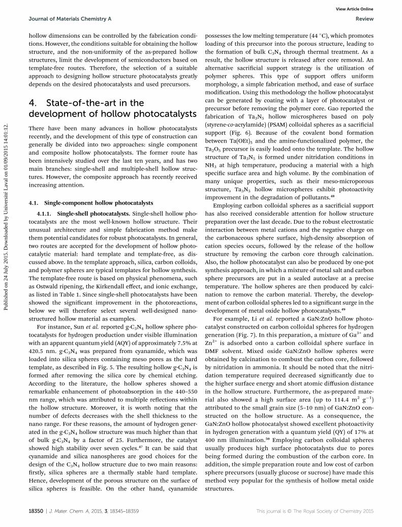
evolution of the hollow CdS originates from the faster diffusionrate of Cd than the excess sulfur in the reaction media throughthe formed CdS shell, which releases the space inside.63 Anothertemplate-free method for the formation of hollow structurephotocatalysts is ion exchange, which is based on the differencein the stability constant of the product. For instance, Chen et al.introduced the formation of hollow structure Bi2WO6 fromBiOBr through anion exchange. The critical parameter for theformation of Bi2WO6 is the solubility product constant Ksp ofBi2WO6, which is minuscule in comparison to that of BiOBr. Forthis reason, the replacement of WO4
2� is thermodynamicallyfavourable, as depicted in Fig. 9B.55
4.1.2. Multi-shell hollow photocatalysts. Multi-shell hollowstructure photocatalysts have recently attracted increasingattention because of their remarkable advantages. By virtue ofthe nanoparticle assembly, multi-shell hollow photocatalystspossess not only low density and high surface area, but alsoabundant inner spaces that overcome the mass transportproblem. Multiple reections within shells improve lightabsorption, leading to the generation of more photo chargecarriers, as illustrated in Fig. 10A.
This journal is © The Royal Society of Chemistry 2015
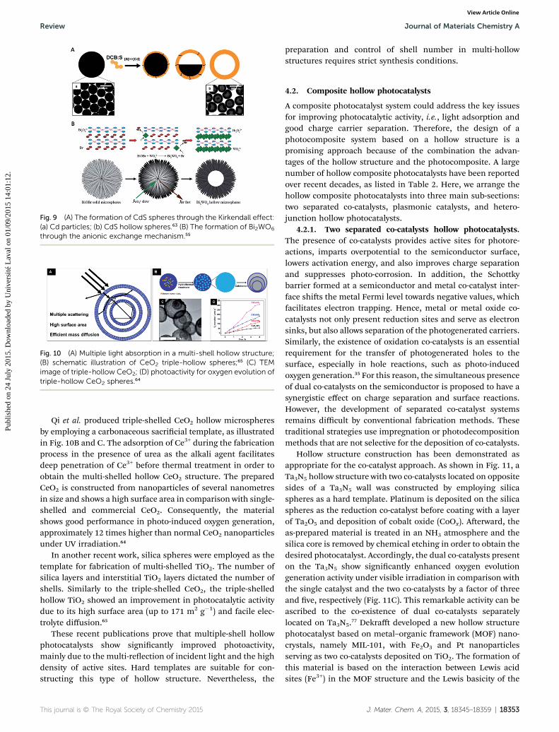
Fig. 9 (A) The formation of CdS spheres through the Kirkendall effect:(a) Cd particles; (b) CdS hollow spheres.63 (B) The formation of Bi2WO6
through the anionic exchange mechanism.55
Fig. 10 (A) Multiple light absorption in a multi-shell hollow structure;(B) schematic illustration of CeO2 triple-hollow spheres;65 (C) TEMimage of triple-hollow CeO2; (D) photoactivity for oxygen evolution oftriple-hollow CeO2 spheres.64
Review Journal of Materials Chemistry A
Publ
ishe
d on
24
July
201
5. D
ownl
oade
d by
Uni
vers
ité L
aval
on
01/0
9/20
15 1
4:01
:12.
View Article Online
Qi et al. produced triple-shelled CeO2 hollow microspheresby employing a carbonaceous sacricial template, as illustratedin Fig. 10B and C. The adsorption of Ce3+ during the fabricationprocess in the presence of urea as the alkali agent facilitatesdeep penetration of Ce3+ before thermal treatment in order toobtain the multi-shelled hollow CeO2 structure. The preparedCeO2 is constructed from nanoparticles of several nanometresin size and shows a high surface area in comparison with single-shelled and commercial CeO2. Consequently, the materialshows good performance in photo-induced oxygen generation,approximately 12 times higher than normal CeO2 nanoparticlesunder UV irradiation.64
In another recent work, silica spheres were employed as thetemplate for fabrication of multi-shelled TiO2. The number ofsilica layers and interstitial TiO2 layers dictated the number ofshells. Similarly to the triple-shelled CeO2, the triple-shelledhollow TiO2 showed an improvement in photocatalytic activitydue to its high surface area (up to 171 m2 g�1) and facile elec-trolyte diffusion.65
These recent publications prove that multiple-shell hollowphotocatalysts show signicantly improved photoactivity,mainly due to the multi-reection of incident light and the highdensity of active sites. Hard templates are suitable for con-structing this type of hollow structure. Nevertheless, the
This journal is © The Royal Society of Chemistry 2015
preparation and control of shell number in multi-hollowstructures requires strict synthesis conditions.
4.2. Composite hollow photocatalysts
A composite photocatalyst system could address the key issuesfor improving photocatalytic activity, i.e., light adsorption andgood charge carrier separation. Therefore, the design of aphotocomposite system based on a hollow structure is apromising approach because of the combination the advan-tages of the hollow structure and the photocomposite. A largenumber of hollow composite photocatalysts have been reportedover recent decades, as listed in Table 2. Here, we arrange thehollow composite photocatalysts into three main sub-sections:two separated co-catalysts, plasmonic catalysts, and hetero-junction hollow photocatalysts.
4.2.1. Two separated co-catalysts hollow photocatalysts.The presence of co-catalysts provides active sites for photore-actions, imparts overpotential to the semiconductor surface,lowers activation energy, and also improves charge separationand suppresses photo-corrosion. In addition, the Schottkybarrier formed at a semiconductor and metal co-catalyst inter-face shis the metal Fermi level towards negative values, whichfacilitates electron trapping. Hence, metal or metal oxide co-catalysts not only present reduction sites and serve as electronsinks, but also allows separation of the photogenerated carriers.Similarly, the existence of oxidation co-catalysts is an essentialrequirement for the transfer of photogenerated holes to thesurface, especially in hole reactions, such as photo-inducedoxygen generation.35 For this reason, the simultaneous presenceof dual co-catalysts on the semiconductor is proposed to have asynergistic effect on charge separation and surface reactions.However, the development of separated co-catalyst systemsremains difficult by conventional fabrication methods. Thesetraditional strategies use impregnation or photodecompositionmethods that are not selective for the deposition of co-catalysts.
Hollow structure construction has been demonstrated asappropriate for the co-catalyst approach. As shown in Fig. 11, aTa3N5 hollow structure with two co-catalysts located on oppositesides of a Ta3N5 wall was constructed by employing silicaspheres as a hard template. Platinum is deposited on the silicaspheres as the reduction co-catalyst before coating with a layerof Ta2O5 and deposition of cobalt oxide (CoOx). Aerward, theas-prepared material is treated in an NH3 atmosphere and thesilica core is removed by chemical etching in order to obtain thedesired photocatalyst. Accordingly, the dual co-catalysts presenton the Ta3N5 show signicantly enhanced oxygen evolutiongeneration activity under visible irradiation in comparison withthe single catalyst and the two co-catalysts by a factor of threeand ve, respectively (Fig. 11C). This remarkable activity can beascribed to the co-existence of dual co-catalysts separatelylocated on Ta3N5.77 Dekra developed a new hollow structurephotocatalyst based on metal–organic framework (MOF) nano-crystals, namely MIL-101, with Fe2O3 and Pt nanoparticlesserving as two co-catalysts deposited on TiO2. The formation ofthis material is based on the interaction between Lewis acidsites (Fe3+) in the MOF structure and the Lewis basicity of the
J. Mater. Chem. A, 2015, 3, 18345–18359 | 18353

Table 2 List of hollow composite photocatalysts
Type Morphology Strategy Application Ref.
Fe2O3/Fe-doped TiO2/Pt Hard template – MIL 101 Hydrogen production 66
Au/TiO2 Hard template – SiO2 spheres Methylene blue degradation 67
Ag/TiO2 Hard template – carbon colloidal spheres Degradation of RhB 68
Ag/AgI Template-free – Kirkendall effect Hydrogen generation 69
Au/CeO2 Hard template – carbon colloidal spheres Reduction of p-nitrophenol 70
TiO2/Au/TiO2 Hard template – SiO2 spheresCO oxidation, H2 production,nitrophenol reduction
71
Fe3O4/TiO2 Hard template – PSA RhB degradation 72
ZnO/TiO2 Hard template – PS Rhodamine 6G degradation 73
CdMoO4@CdS Template free – ion exchange RhB degradation 74
GO/TiO2 Hard template – SiO2 spheres RhB degradation 75
Au@r-GO/TiO2 Hard template – SiO2 spheres RhB degradation 76
Journal of Materials Chemistry A Review
Publ
ishe
d on
24
July
201
5. D
ownl
oade
d by
Uni
vers
ité L
aval
on
01/0
9/20
15 1
4:01
:12.
View Article Online
titanium precursor. The loading of TiO2 on MIL-101 is facili-tated by hydrolysis before deposition of the Pt as second co-catalysts. Recently, our group developed a hollow TiO2 structure
18354 | J. Mater. Chem. A, 2015, 3, 18345–18359
with Fe2O3 and platinum oxide (PtOx), which serve as twoseparate co-catalysts deposited on opposite sides of a hollowwall, illustrated in Fig. 12. Coating with TiO2 is based on the
This journal is © The Royal Society of Chemistry 2015

Fig. 11 (A) Illustration of the photoactivity improvement in a separatedco-catalyst with a hollow structure; (B) SEM image of hollow Pt/Ta3N5;(C) photoactivity for oxygen generation under visible light of hollow Pt/Ta3N5/CoOx.77
Review Journal of Materials Chemistry A
Publ
ishe
d on
24
July
201
5. D
ownl
oade
d by
Uni
vers
ité L
aval
on
01/0
9/20
15 1
4:01
:12.
View Article Online
interaction between Lewis acid sites exposed on unsaturatedmetal centres of dehydrated MIL-88B and the Lewis basic tita-nium precursor. The hollow TiO2 co-catalyst material is subse-quently generated by calcination. The amount of hydrogenproduced using this material demonstrates that the preparedphotosystem has efficient photoactivity.78
4.2.2. Plasmonic hollow photocatalysts. An importantstrategy for the development of composite photocatalyticsystems is the exploitation of surface plasmon resonance innoble metals such as Au and Ag. A hollow structure plasmoniccomposite displays improved photo-activity compared withnormal plasmonic nanocomposites due to the increasedcontact between the metal nanoparticles and the support.79
Fig. 12 (A) Schematic illustration of Fe2O3–TiO2–PtOx preparationfrom MIL-88B; (B) TEM images of hollow Fe2O3–TiO2–PtOx; (C)amount of hydrogen generated under visible light irradiation.78
This journal is © The Royal Society of Chemistry 2015
Very recently, our group has developed three-dimensionalphotonic hollow structure Au/TiO2. Based on the layer-by-layer(LBL) self-assembly technique, a three-dimensional orderedassembly of thin-shell Au/TiO2 hollow nanospheres (HNSs) wasfabricated, as illustrated in Fig. 13. Due to the hydrophilicsurface of the silica sphere, polyethylenimine (PEI) is attractedthrough electrostatic interaction and makes the surface chargepositive. Then, titanium nano-disks with negative surfacecharge are deposited by the LBL technique via electrostaticinteraction with PEI, followed by loading with HAuCl4 toproduce TND–PEI–AuCl4/SiO2. Assembly of TND–PEI–AuCl4/SiO2 is performed by centrifugation at low speed, followed bycalcination to obtain the Au/TiO2/SiO2 ordered structure. Thesilica core is then removed by NaOH solution to release theordered Au/TiO2 hollow structure. This unique high surfacestructure shows a photonic stop band at 550–620 nm, whichmatches the surface plasmon resonance absorption of goldnanoparticles. These ordered Au/TiO2 hollow spheres showremarkable activity in the decomposition of isopropanolcompared to the same photocatalyst without the orderedstructure.80
4.2.3. Hollow heterojunction photocatalysts. It can beargued that the development of heterojunction structure pho-tocatalysts is the most critical approach to developing efficientphotocatalytic materials, as the fundamental requirements ofphotocatalytic materials, such as high crystallinity, efficientlight absorption, and proper charge separation, can be satisedsimultaneously by combining two or many semiconductors.Consequently, numerous reports have been published on the
Fig. 13 (A) Schematic illustration of the fabrication of Au/TiO2-3DHNSs; (B) SEM, and (C and D) TEM and STEM of Au/TiO2-3DHNSs;(E) UV-Vis spectroscopy of Au/TiO2-3DHNSs; (F) amount of CO2
generated under visible light illumination, (1) Au–TiO2 (P25); (2) Au/TiO2-3DHNSs; (3) crushed Au/TiO2-3DHNSs; (4) disordered Au/TiO2-HNSs.80
J. Mater. Chem. A, 2015, 3, 18345–18359 | 18355

Fig. 15 (A) formation of hollow structure ZnFe2O4/ZnO; (B and C) SEMand TEM images, respectively, of hollow structure ZnFe2O4/ZnO; (D)amount of hydrogen generated on hollow structure ZnFe2O4/ZnO; (E)schematic diagram of energy band structures and the expectedtransfer direction of electron–hole pairs in the ZnFe2O4/ZnO heter-ostructures under visible light irradiation.82
Journal of Materials Chemistry A Review
Publ
ishe
d on
24
July
201
5. D
ownl
oade
d by
Uni
vers
ité L
aval
on
01/0
9/20
15 1
4:01
:12.
View Article Online
development of heterojunction photocatalysts. However, theconventional method of photo composite fabrication is themixing of many individual semiconductors, which leads tosmall surface areas and an ineffective incident light utilization.The fabrication of composite photocatalysts based on a hollowstructure overcomes these drawbacks and shows promise as agood candidate for production of an efficient articialphotosystem.
To date, a variety of composite hollow photocatalysts havebeen reported. For instance, Ta3N5 quantum dots were appliedin situ to a TaON hollow structure wall that was produced usinga polymer sphere template, as illustrated in Fig. 14. Thecomposite photocatalyst showed excellent activity for oxygengeneration due to the close contact between the Ta3N5 and theTaON hollow spheres, with apparent quantum efficiencies up to67% under 420 nm light.81
In another work, a hollow heterojunction system comprisingZnFe2O4 and ZnO formed on a carbonaceous sacricial supportwas reported, as illustrated in Fig. 15. Simultaneous adsorptionof Zn2+ and Fe3+ precursors on the negative surface of carboncolloidal spheres causes the formation of the hollow hetero-junction structure aer calcination. The resulting hollowmicrostructures are constructed by ZnO and ZnFe2O4 with a sizeof ca. 15 nm (Fig. 15B and C). Surprisingly, this nano-sizedheterostructure demonstrates remarkable photoactivity forhydrogen evolution without co-catalysts under visible irradia-tion. This enhancement in photoactivity can be attributed to thehomogeneous distribution in the hollow shell of ZnO andZnFe2O4 as nanoscale particles, which lead to signicantlyimproved charge separation. This work shows that theconstruction of nanocomposite photocatalysts on the hollowstructure can solve the current problems of nanocomposites,i.e., the reduction of charge recombination while exposing ahigh density of active sites. Moreover, this type of structurecould be a lot more convenient for recycling than that ofnanocomposite systems alone.82
Fig. 14 (A) Schematic illustration of the production of a Ta3N5/TaONhollow composite photocatalyst; (B and C) TEM images of TaON andTa3N5/TaON, respectively.81
18356 | J. Mater. Chem. A, 2015, 3, 18345–18359
In addition to materials with a semiconductor–semi-conductor heterojunction, the development of materials withgraphene, which has the unique properties of extra-largesurface area, high electron mobility at room temperature, andexceptional thermal conductivity, have been paid considerableattention. The superior mechanical properties and electrontransfer ability of graphene helps the composite system prolongcharge carrier lifetime and suppresses electron–hole recombi-nation.83–85 Naturally, hollow structure composites have beenproduced using this material.
For example, robust hollow spheres constructed from gra-phene and titania nanosheets have been reported by Tu et al.Titania nanosheets and graphene were sequentially depositedon a PMMA sphere hard template by electrostatic interactionbetween titania nanosheets (a negatively charged surface), PEI(a polycation), and graphene (a negatively charged surface), asshown in Fig. 16. The as-prepared hollow structure promotesCO2 photo conversion to CH4 which is ten times higher than the
Fig. 16 (A) Schematic illustration of TiO2/GO hollow compositeformation: (1) PEI, (2) Ti0.91O2, (3) PEI, (4) GO nanosheet, (5) five repeatsof steps 1–4, (6) microwave treatment; (B, C, D) SEM images of barePMMA spheres, PEI/Ti0.91O2/PEI/GO@PMMA, and (G–Ti0.91O2)5 hollowspheres, respectively; (E) TEM image of (G–Ti0.91O2)5 hollow spheres;(F) CO2 reduction by (G–Ti0.91O2)5 hollow spheres.86
This journal is © The Royal Society of Chemistry 2015
Review Journal of Materials Chemistry A
Publ
ishe
d on
24
July
201
5. D
ownl
oade
d by
Uni
vers
ité L
aval
on
01/0
9/20
15 1
4:01
:12.
View Article Online
commercial product P25. This signicant enhancement inphotoactivity can be attributed to the high charge separation ofthe titania nanosheet and graphene heterojunction based onthe hollow structure.86 Similarly, graphene deposited on TiO2
hollow microspheres based on silica or PSS sphere templateshas also been reported. Also, hollow heterojunction photo-catalysts comprising graphene/ZnO and graphene/CeO2 havebeen reported, and show excellent photoactivity in the decom-position of organic pollutants.
The study discussed above indicates that construction ofhollow composite structures is becoming an attractive objectivethat will continue to attract increasing attention from photo-catalytic material developers in the future. In addition,employment of hard templates for designing hollow structuresis the most appropriate approach to these materials because ofthe requirement of multiple steps during the fabricating period,an important feature that produces materials capable ofimproved charge separation. Moreover, the calcination step isprobably necessary in order to improve the contact areabetween individual components.
5. Conclusions
Exploitation of sunlight for energy production and environ-mental remediation is one of the most crucial research topics ofthe 21st century. Photocatalysis based on semiconductors is animportant approach to the utilization of the abundant energyfrom the sun. Unfortunately, inefficient light absorption andphotogenerated charge carrier recombination limits semi-conductor-based photocatalyst performance. Thus, develop-ment of articial photosystems that require both efficientsunlight exploitation and charge separation is the mostimportant challenge to be overcome in current photocatalysts.
Utilization of nanoscale photocatalytic systems is a prom-ising approach that can take advantage of the high surface areaand high active sites in such materials. Construction of nano-particle photocatalysts onmicro-scale hollow structures exploitsthe advantages of nano-sized materials in order to reducecharge recombination. In addition, hollow structures possessunique properties that enhance their light absorption ability.For these reasons, the hollow photocatalysts show greatpromise as candidates for use in efficient articialphotosystems.
Over the last decade, the preparation of hollow photo-catalysts has relied mainly on hard template and template-freestrategies. In the former, silica spheres, polymer spheres, andcarbon colloidal spheres function as the sacricial support forpreparation of the hollow structure. Additionally, the use ofmetal–organic frameworks as the template has attractedincreasing research attention recently. The template-freeapproach to realising hollow structures is mainly based onphysical-chemical phenomena, such as Ostwald ripening, theKirkendall effect, and ionic exchange.
In this review, we have classied the current study of hollowstructure photocatalysts into single-shell, multiple-shell, andcomposite hollow photosystems, all of which employ a diversearray of semiconductors for different applications. To date, the
This journal is © The Royal Society of Chemistry 2015
vast majority of publications are concerned with single-shellmaterials, due to their simple fabrication methodology. More-over, multiple-shell hollow structures with a single semi-conductor are rarely reported because of the complexity of theirfabrication.
Nanocomposite photocatalysts, the most crucial approach torobust photosystems based on hollow structure materials, stillpresents many challenges. These challenges are mainly con-cerned with the development of fabrication strategies and thechoice of precursors. Hard templates seem to be the mostappropriate sacricial support because the amount and loadingorder of the precursors are controllable. Hence, the number andlocation of individual components in the photocatalyticcomposite can be precisely dictated.
We believe that photo nanocomposites based on hollowstructures offer tremendous promise for the development offuture photocatalysts for the following reasons: (i) the forma-tion of large surface area composites, which is impossible byconventional methods; (ii) the high interface area between theindividual components, which is an essential factor in sup-pressing charge recombination; (iii) selective deposition of co-catalysts on the different components in the composite systemin order to further boost the photoactivity; (iv) enhancement oflight absorption ability.
Acknowledgements
This work was supported by the Natural Science and Engi-neering Research Council of Canada (NSERC) through theCollaborative Research and Development (CRD) and Discoverygrants.
Notes and references
1 A. Fujishima, Nature, 1972, 238, 37–38.2 C. Chen, W. Ma and J. Zhao, Chem. Soc. Rev., 2010, 39, 4206–4219.
3 M. R. Gholipour, C.-T. Dinh, F. Beland and T.-O. Do,Nanoscale, 2015, 7, 8187–8208.
4 H. Tong, S. Ouyang, Y. Bi, N. Umezawa, M. Oshikiri and J. Ye,Adv. Mater., 2012, 24, 229–251.
5 Y. Hou, X. Li, Q. Zhao, X. Quan and G. Chen, Environ. Sci.Technol., 2010, 44, 5098–5103.
6 M. Singh, I. Salvado-Estivill and G. Li Puma, AIChE J., 2007,53, 678–686.
7 H. Wang, L. Zhang, Z. Chen, J. Hu, S. Li, Z. Wang, J. Liu andX. Wang, Chem. Soc. Rev., 2014, 43, 5234–5244.
8 K. Wang, Q. Li, B. Liu, B. Cheng, W. Ho and J. Yu, Appl.Catal., B, 2015, 176–177, 44–52.
9 J. Li and N. Wu, Catal. Sci. Technol., 2015, 5, 1360–1384.10 G. Liu, H. G. Yang, J. Pan, Y. Q. Yang, G. Q. Lu and
H.-M. Cheng, Chem. Rev., 2014, 114, 9559–9612.11 Q. Weng, Y. Ide, X. Wang, X. Wang, C. Zhang, X. Jiang,
Y. Xue, P. Dai, K. Komaguchi, Y. Bando and D. Golberg,Nano Energy, 2015, 16, 19–27.
12 Q. Xu, J. Yu, J. Zhang, J. Zhang and G. Liu, Chem. Commun.,2015, 51, 7950–7953.
J. Mater. Chem. A, 2015, 3, 18345–18359 | 18357

Journal of Materials Chemistry A Review
Publ
ishe
d on
24
July
201
5. D
ownl
oade
d by
Uni
vers
ité L
aval
on
01/0
9/20
15 1
4:01
:12.
View Article Online
13 X. Chen, L. Liu, P. Y. Yu and S. S. Mao, Science, 2011, 331,746–750.
14 L. Yang, H. Zhou, T. Fan and D. Zhang, Phys. Chem. Chem.Phys., 2014, 16, 6810–6826.
15 L. Li, P. A. Salvador and G. S. Rohrer, Nanoscale, 2014, 6, 24–42.
16 R. Marschall, Adv. Funct. Mater., 2014, 24, 2421–2440.17 P. Zhou, J. Yu and M. Jaroniec, Adv. Mater., 2014, 26, 4920–
4935.18 Y. Wang, Q. Wang, X. Zhan, F. Wang, M. Safdar and J. He,
Nanoscale, 2013, 5, 8326–8339.19 J. Low, S. Cao, J. Yu and S. Wageh, Chem. Commun., 2014, 50,
10768–10777.20 H. Wang, L. Zhang, Z. Chen, J. Hu, S. Li, Z. Wang, J. Liu and
X. Wang, Chem. Soc. Rev., 2014, 43, 5234–5244.21 M. Dahl, Y. Liu and Y. Yin, Chem. Rev., 2014, 114, 9853–9889.22 R. Jiang, B. Li, C. Fang and J. Wang, Adv. Mater., 2014, 26,
5274–5309.23 J. M. Coronado, F. Fresno, M. D. Hernandez-Alonso and
R. Portela, Design of advanced photocatalytic materials forenergy and environmental applications, Springer, 2013.
24 Y. Ma, X. Wang, Y. Jia, X. Chen, H. Han and C. Li, Chem. Rev.,2014, 114, 9987–10043.
25 W.-J. Ong, L.-L. Tan, S.-P. Chai, S.-T. Yong andA. R. Mohamed, ChemSusChem, 2014, 7, 690–719.
26 Y. Lan, Y. Lu and Z. Ren, Nano Energy, 2013, 2, 1031–1045.27 M. Pelaez, N. T. Nolan, S. C. Pillai, M. K. Seery, P. Falaras,
A. G. Kontos, P. S. M. Dunlop, J. W. J. Hamilton,J. A. Byrne, K. O'Shea, M. H. Entezari and D. D. Dionysiou,Appl. Catal., B, 2012, 125, 331–349.
28 B. Ma, F. Wen, H. Jiang, J. Yang, P. Ying and C. Li, Catal.Lett., 2010, 134, 78–86.
29 W.-J. Ong, L.-L. Tan, S.-P. Chai and S.-T. Yong, Dalton Trans.,2015, 1249–1257.
30 J. Ran, J. Zhang, J. Yu, M. Jaroniec and S. Z. Qiao, Chem. Soc.Rev., 2014, 43, 7787–7812.
31 S. Bai, L. Wang, X. Chen, J. Du and Y. Xiong, Nano Res., 2015,8, 175–183.
32 Q. Xiang, B. Cheng and J. Yu, Angew. Chem., Int. Ed., 2015, 54,2–19.
33 W.-J. Ong, L.-L. Tan, S.-P. Chai, S.-T. Yong and A. Mohamed,Nano Res., 2014, 7, 1528–1547.
34 W.-J. Ong, J.-J. Yeong, L.-L. Tan, B. T. Goh, S.-T. Yong andS.-P. Chai, RSC Adv., 2014, 4, 59676–59685.
35 S. Bai, J. Jiang, Q. Zhang and Y. Xiong, Chem. Soc. Rev., 2015,44, 2893–2939.
36 J. Liu, Y. Liu, N. Liu, Y. Han, X. Zhang, H. Huang, Y. Lifshitz,S.-T. Lee, J. Zhong and Z. Kang, Science, 2015, 347, 970–974.
37 J. Tian, Y. Leng, Z. Zhao, Y. Xia, Y. Sang, P. Hao, J. Zhan,M. Li and H. Liu, Nano Energy, 2015, 11, 419–427.
38 C. Wang and D. Astruc, Chem. Soc. Rev., 2014, 43, 7188–7216.39 F.-H. Du, B. Li, W. Fu, Y.-J. Xiong, K.-X. Wang and J.-S. Chen,
Adv. Mater., 2014, 26, 6145–6150.40 M.-M. Titirici, M. Antonietti and A. Thomas, Chem. Mater.,
2006, 18, 3808–3812.41 J. B. Joo, Q. Zhang, I. Lee, M. Dahl, F. Zaera and Y. Yin, Adv.
Funct. Mater., 2012, 22, 166–174.
18358 | J. Mater. Chem. A, 2015, 3, 18345–18359
42 H. Li, Z. Bian, J. Zhu, D. Zhang, G. Li, Y. Huo, H. Li and Y. Lu,J. Am. Chem. Soc., 2007, 129, 8406–8407.
43 Z. Wang, J. Hou, C. Yang, S. Jiao, K. Huang and H. Zhu,Energy Environ. Sci., 2013, 6, 2134–2144.
44 X. W. Lou, Y. Wang, C. Yuan, J. Y. Lee and L. A. Archer, Adv.Mater., 2006, 18, 2325–2329.
45 H. J. Fan, M. Knez, R. Scholz, D. Hesse, K. Nielsch,M. Zacharias and U. Gosele, Nano Lett., 2007, 7, 993–997.
46 Y. Zhu, D. Fan and W. Shen, Langmuir, 2008, 24, 11131–11136.
47 J. Sun, J. Zhang, M. Zhang, M. Antonietti, X. Fu and X. Wang,Nat. Commun., 2012, 1139.
48 R. Gao, S. Zhou, M. Chen and L. Wu, J. Mater. Chem., 2011,21, 17087–17090.
49 X. Sun and Y. Li, Angew. Chem., Int. Ed., 2004, 43, 3827–3831.50 Y. Li, L. Zhu, Y. Yang, H. Song, Z. Lou, Y. Guo and Z. Ye,
Small, 2015, 11, 871–876.51 J. B. Joo, Q. Zhang, I. Lee, M. Dahl, F. Zaera and Y. Yin, Adv.
Funct. Mater., 2012, 22, 166–174.52 J. Yu and X. Yu, Environ. Sci. Technol., 2008, 42, 4902–4907.53 Q. Li, W. Chen, M. Ju, L. Liu and E. Wang, J. Solid State
Chem., 2011, 184, 1373–1380.54 X.-J. Dai, Y.-S. Luo, W.-D. Zhang and S.-Y. Fu, Dalton Trans.,
2010, 3426–3432.55 H. Cheng, B. Huang, Y. Liu, Z. Wang, X. Qin, X. Zhang and
Y. Dai, Chem. Commun., 2012, 48, 9729–9731.56 W. Yin, W. Wang and S. Sun, Catal. Commun., 2010, 11, 647–
650.57 J. Zhang, S. Liu, J. Yu and M. Jaroniec, J. Mater. Chem., 2011,
21, 14655–14662.58 D. Chen and J. Ye, Adv. Funct. Mater., 2008, 18, 1922–1928.59 J. Huang, R. Ma, Y. Ebina, K. Fukuda, K. Takada and
T. Sasaki, Chem. Mater., 2010, 22, 2582–2587.60 Y. Huo, M. Miao, Y. Zhang, J. Zhu and H. Li, Chem. Commun.,
2011, 47, 2089–2091.61 Y. Li, X. Cheng, X. Ruan, H. Song, Z. Lou, Z. Ye and L. Zhu,
Nano Energy, 2015, 12, 775–784.62 L. Cao, D. Chen and R. A. Caruso, Angew. Chem., 2013, 125,
11192–11197.63 M. Ibanez, J. Fan, W. Li, D. Cadavid, R. Nafria, A. Carrete and
A. Cabot, Chem. Mater., 2011, 23, 3095–3104.64 J. Qi, K. Zhao, G. Li, Y. Gao, H. Zhao, R. Yu and Z. Tang,
Nanoscale, 2014, 6, 4072–4077.65 S. H. Hwang, J. Yun and J. Jang, Adv. Funct. Mater., 2014, 24,
7619–7626.66 K. E. deKra, C. Wang and W. Lin, Adv. Mater., 2012, 24,
2014–2018.67 J. Lu, P. Zhang, A. Li, F. Su, T. Wang, Y. Liu and J. Gong,
Chem. Commun., 2013, 49, 5817–5819.68 S. Wang, H. Qian, Y. Hu, W. Dai, Y. Zhong, J. Chen and
X. Hu, Dalton Trans., 2013, 1122–1128.69 C. An, J. Wang, J. Liu, S. Wang and Q.-H. Zhang, RSC Adv.,
2014, 4, 2409–2413.70 P. Xu, R. Yu, H. Ren, L. Zong, J. Chen and X. Xing, Chem. Sci.,
2014, 5, 4221–4226.71 J. Chen, D. Wang, J. Qi, G. Li, F. Zheng, S. Li, H. Zhao and
Z. Tang, Small, 2015, 11, 420–425.
This journal is © The Royal Society of Chemistry 2015

Review Journal of Materials Chemistry A
Publ
ishe
d on
24
July
201
5. D
ownl
oade
d by
Uni
vers
ité L
aval
on
01/0
9/20
15 1
4:01
:12.
View Article Online
72 S. Xuan, W. Jiang, X. Gong, Y. Hu and Z. Chen, J. Phys. Chem.C, 2008, 113, 553–558.
73 M. Agrawal, S. Gupta, A. Pich, N. E. Zafeiropoulos andM. Stamm, Chem. Mater., 2009, 21, 5343–5348.
74 P. Madhusudan, J. Zhang, B. Cheng and J. Yu, Phys. Chem.Chem. Phys., 2015, 17, 15339–15347.
75 J. Zhang, Z. Zhu, Y. Tang and X. Feng, J. Mater. Chem. A,2013, 1, 3752–3756.
76 M. Wang, J. Han, H. Xiong and R. Guo, Langmuir, 2015, 31,6220–6228.
77 D. Wang, T. Hisatomi, T. Takata, C. Pan, M. Katayama,J. Kubota and K. Domen, Angew. Chem., Int. Ed., 2013, 52,11252–11256.
78 M.-H. Pham, C.-T. Dinh, G.-T. Vuong, N.-D. Ta and T.-O. Do,Phys. Chem. Chem. Phys., 2014, 16, 5937–5941.
79 H. Ren, R. Yu, J. Wang, Q. Jin, M. Yang, D. Mao, D. Kisailus,H. Zhao and D. Wang, Nano Lett., 2014, 14, 6679–6684.
This journal is © The Royal Society of Chemistry 2015
80 C.-T. Dinh, H. Yen, F. Kleitz and T.-O. Do, Angew. Chem., Int.Ed., 2014, 53, 6618–6623.
81 Z. Wang, J. Hou, S. Jiao, K. Huang and H. Zhu, J. Mater.Chem., 2012, 22, 21972–21978.
82 H. Song, L. Zhu, Y. Li, Z. Lou, M. Xiao and Z. Ye, J. Mater.Chem. A, 2015, 3, 8353–8360.
83 W.-J. Ong, L.-L. Tan, S.-P. Chai and S.-T. Yong, Chem.Commun., 2015, 51, 858–861.
84 F. Bonaccorso, L. Colombo, G. Yu, M. Stoller, V. Tozzini,A. C. Ferrari, R. S. Ruoff and V. Pellegrini, Science, 2015,347, DOI: 10.1126/science.1246501.
85 W.-J. Ong, L.-L. Tan, S.-P. Chai, S.-T. Yong andA. R. Mohamed, Nano Energy, 2015, 13, 757–770.
86 W. Tu, Y. Zhou, Q. Liu, Z. Tian, J. Gao, X. Chen, H. Zhang,J. Liu and Z. Zou, Adv. Funct. Mater., 2012, 22, 1215–1221.
J. Mater. Chem. A, 2015, 3, 18345–18359 | 18359