journal of materials chemistry c · chem. c, 2016, 4, 295--304 this ournal is ' the royal...
TRANSCRIPT

This journal is©The Royal Society of Chemistry 2016 J. Mater. Chem. C, 2016, 4, 295--304 | 295
Cite this: J.Mater. Chem. C, 2016,
4, 295
Vertical SnO2 nanosheet@SiC nanofibers withhierarchical architecture for high-performancegas sensors†
Bing Wang,a Yingde Wang,*a Yongpeng Lei,*b Song Xie,a Nan Wu,a Yanzi Gou,a
Cheng Han,a Qi Shia and Dong Fangc
Increasing demands for detection of harmful gases in harsh environments have stimulated considerable
efforts to develop a novel gas sensor with high sensitivity, superior thermal/chemical stability and fast
response/recovery rate. In this paper, we report the vertical growth of ultrathin SnO2 nanosheets (SnO2
NSs) on quasi-one-dimensional SiC nanofibers (SiC NFs) forming a hierarchical architecture via a simple
hydrothermal method. In comparison to pure SnO2 NSs, the SnO2 NS@SiC NF hierarchical composite
shows an ultrafast response/recovery rate, high sensitivity, and simultaneously excellent reproducibility
to various target gases including ethanol, methanol, hydrogen, isopropanol, acetone and xylene, even at
high temperature. The response times are less than 5 s with corresponding recovery times o15 s.
Furthermore, the SnO2 NS@SiC NF gas sensor shows a superior sensing selectivity and long-term
stability to ethanol. The hierarchical architecture and synergetic effect of the SnO2–SiC heterojunction
as well as plenty of active sites from the vertically ultrathin SnO2 NSs have critical effect on the superior
sensing performance of SnO2 NS@SiC NFs. This work highlights the possibility to develop a novel high-
performance gas sensor for application in harsh environments.
Introduction
In situ detection of gases hazardous to the environment andhuman health has attracted increasing attention.1,2 In the pastfew decades, metal-oxide semiconductor based gas sensorshave been extensively investigated for various daily and industrialapplications due to their outstanding sensing performance, evenin harsh environments.1,3,4 Thereto, n-type tin dioxide (SnO2) hasbeen proved to be promising for gas sensing by virtue of itsexcellent photoelectrical properties, superior thermal stability(melt point is 1127 1C), chemical inertness, low cost and non-toxicity.5,6 The sensing mechanism of SnO2 gas sensors is basedon the electrical conductivity change of the sensor in differenttypes of target gases.7 In general, when SnO2 is exposed to air,the electron from its conduction band (CB) will transfer to theabsorbed oxygen, resulting in the production of tremendous
oxygen species (O2�, O� or O2�) on the SnO2 surface. Simulta-
neously, an electron-depleted surface layer forms on SnO2, whichleads to a decrease in the electrical conductivity. In reducinggases (e.g., ethanol, hydrogen, and methanol), the target gaseswill react with those oxygen species, freeing electrons back to theSnO2 surface, leading to an increase in the sensor conductivity.8
In oxidizing gases (electron acceptor), more electrons aregrabbed by the absorbed gases, further lowering the electricalconductivity of the sensor. Recently, SnO2 with different nano-structures (nanosheets, nanoparticles, nanowires, nanospheres,nanotubes, etc.) has been reported for detecting various types ofgases.8 Moreover, to reach higher sensitivity, strategies such asdoping with noble metals,9,10 forming heterojunctions withother semiconductors11,12 and exposing active facets13 have beendemonstrated.
Besides sensitivity and durability, the response/recoverybehavior is also a vital characteristic parameter for gas sensors.With a fast response/recovery rate, large loss/harm can be avertedin time. However, achieving rapid response and recovery character-istics for these nanostructured gas sensors is still a challenge.14 Topromote the response/recovery speed, a promising way is to con-struct hierarchical architectures, which can simultaneously avoidthe agglomeration of SnO2 nanostructures and facilitate the diffu-sion (adsorption and desorption) of target gas.15 For instance, Leeet al. have demonstrated that the core–shell ZnO–SnO2@carbon
a Science and Technology on Advanced Ceramic Fibres and Composites Laboratory,
National University of Defense Technology, 109 Deya Road, Changsha 410073,
P. R. China. E-mail: [email protected] College of Basic Education, National University of Defense Technology,
Changsha 410073, P. R. China. E-mail: [email protected] College of Materials Science and Engineering, Wuhan Textile University,
Wuhan 430074, P. R. China
† Electronic supplementary information (ESI) available: Figures and tables. SeeDOI: 10.1039/c5tc02792f
Received 5th September 2015,Accepted 27th November 2015
DOI: 10.1039/c5tc02792f
www.rsc.org/MaterialsC
Journal ofMaterials Chemistry C
PAPER
Publ
ishe
d on
30
Nov
embe
r 20
15. D
ownl
oade
d by
Bei
jing
Uni
vers
ity o
f C
hem
ical
Tec
hnol
ogy
on 1
3/03
/201
6 08
:58:
53. View Article Online
View Journal | View Issue

296 | J. Mater. Chem. C, 2016, 4, 295--304 This journal is©The Royal Society of Chemistry 2016
nanofibers exhibited excellent sensing performance including fastresponse/recovery properties, high sensitivity and ultralow detec-tion limit.16 The polypyrrole/SnO2 hybrid also showed very fastresponse and high sensitivity to ammonia gas.17 Three-dimensional mesoporous graphene aerogel has been utilizedto support SnO2 nanocrystals for a high performance NO2 gassensor.18 However, most of the reported substrates includingcarbonaceous materials (graphene, carbon nanotubes, carbonnanofibers, etc.) and organic substrates (poly(ethylene terephthalate),polypyrrole and polyimide) cannot meet the requirements to applyin certain fields like ethanol direct solid oxide fuel cells (EDSOFCs),power generation, aerospace, automotive, avionics, industrialprocess control, nuclear power and well-logging industries dueto the harsh work environments (e.g., high temperatures,corrosive environments, and high frequency).19–23 For instance,ethanol gas sensors have been widely applied in breath analyzersfor drivers, detecting ethanol in foodstuff experiments to assessthe development of bacteria and fungi in food and monitoringthe chemical processes in chemical industries.24 However, mostof the reported studies were focused on the low/room temperatureethanol gas sensors because they are more desired for applicationin the fields mentioned above. But these ethanol sensors cannotsatisfy the requirements to monitor the ethanol leakage and/or itstotal combustion process in the EDSOFCs, whose operatingtemperature is typically in the range of 500–1000 1C.22,23 Hence,it is more desired but challenging to develop a novel gas sensorcapable of withstanding aforementioned harsh environments.
As a wide band gap semiconductor, silicon carbide (SiC)has emerged as an ideal candidate for application in harshenvironments.25 More recently, SiC based gas sensors haveattracted increasing attention due to their chemical inertness,excellent thermal stability, high thermal conductivity, high elec-tron mobility, and compatibility with conventional Si-basedintegrated devices.26,27 The high electron mobility of SiC isbeneficial to quickly shuttle the charge carriers, which offersan opportunity to design the SiC based gas sensor with anultrafast response/recovery rate. Therefore, combining SiC withhighly reactive SnO2 is expected to develop a novel high perfor-mance gas sensor capable of applying in harsh environments.Furthermore, it has been demonstrated that the composite ofSnO2 nanobelt@SiC foams showed efficient performance to detectlow concentration of NH3 and NO2,28 whereas the response/recovery speed was very slow.
In the present paper, ultrathin SnO2 nanosheets (SnO2 NSs)were in situ grown on the quasi-one-dimensional SiC nano-fibers (SiC NFs) forming a hierarchical SnO2 NS@SiC NFcomposite via a simple hydrothermal method. The synthesizedSnO2 NS@SiC NF sample shows a high sensitivity, excellentreproducibility, outstanding selectivity, long-term stability andparticularly ultrafast response/recovery speed toward ethanol.Such a superior sensing performance is attributed to thesynergetic effect of SnO2 and SiC and the hierarchical archi-tectures as well as plenty of active sites from the verticallyultrathin nanosheets with large surface to volume ratios. Thiswork demonstrates a simple strategy to design a high perfor-mance gas sensor which can be applied in harsh environments.
Experimental sectionMaterials
Polyacrylonitrile (PAN, Mn = 120 000 g mol�1, Kaneka, Japan), Sipowders (200 mesh, Sinopharm, China), tin dichloride dihy-drate (SnCl2�2H2O, Sigma-Aldrich Co., UK), mercaptoacetic acid(MA, Sigma-Aldrich Co., UK), N,N-dimethylformamide (DMF,Hengxing, China), NaOH (Sigma-Aldrich Co., UK) and HCl (37 wt%,Hengxing, China) were of all analytical reagents and usedas-received without any further purification.
Fabrication of mesoporous SiC NFs
Typically, 1.2 g of PAN powders were dissolved in 10 ml of DMFunder vigorous stirring at 30 1C for 5 h to prepare the spinningsolution. And then the homogeneous spinning solution wasloaded into a 10 ml volume plastic syringe with a needle of0.8 mm inner diameter. Electrospinning was carried out with apower supply (Dongwen, China) of 18 kV applied on the needleand the aluminum foil film collector with a distance of 25 cm.The feed rate was kept at 0.9 ml h�1 using a syringe pump(Longer Pump LSP02-1B, China). After curing the as-receivedPAN nanofibers at 260 1C for 1 h in flowing air (1 1C min�1),the obtained nanofibers were carbonized at 1000 1C for 1 h(2 1C min�1) to obtain CNFs. To synthesize SiC NFs, excessive Sipowders were placed at the bottom of the alumina crucible andthe as-received CNFs were laid on the top of the silicon powderswith a distance of 1.5 cm. Then the alumina crucible washeated to 1500 1C for 5 h (10 1C min�1) in a horizontal furnace(Tianjin Zhonghuan, China) under an Ar atmosphere.
Alkali treatment of the SiC NFs
Prior to hydrothermal reaction, the resultant SiC NFs weretreated with alkali solution. In detail, 25 mg of SiC NFs wereimmersed in 20 ml of NaOH solution (5 M) for 12 h at roomtemperature. Afterward, the treated SiC NFs were washed withdeionized water 5 times and dried at 80 1C for 12 h.
Fabrication of the hierarchical SnO2 NS@SiC NFs
SnO2 NSs were in situ grown on the alkali-treated SiC NFs by asimple hydrothermal method. Typically, 0.1 g SnCl2�2H2O wasdissolved in 30 ml MA solution (10 mM), followed by adding0.5 g urea and 0.5 ml HCl solution. The mixture solution wasstirred for 2 min in air at 25 1C and then was transferred intothe Teflon-lined stainless-steel autoclave. Subsequently, 10 mgof the basic-treated SiC NFs were immersed into the abovesolution. The autoclave was sealed up and heated to the targettemperature (100–180 1C) in an electric oven and maintainedfor 6 h. After naturally cooling to the room temperature, theresultant sample was washed with a mixture solvent of ethanoland water (v/v = 1 : 1) several times and dried at 80 1C for 12 h.Finally, the samples were calcined at 600 1C for 2 h with aheating rate of 5 1C min�1.
Characterization
The morphological features of the catalysts were analyzedby using a Hitachi S-4800 field-emission scanning electron
Paper Journal of Materials Chemistry C
Publ
ishe
d on
30
Nov
embe
r 20
15. D
ownl
oade
d by
Bei
jing
Uni
vers
ity o
f C
hem
ical
Tec
hnol
ogy
on 1
3/03
/201
6 08
:58:
53.
View Article Online

This journal is©The Royal Society of Chemistry 2016 J. Mater. Chem. C, 2016, 4, 295--304 | 297
microscope (FE-SEM) with an acceleration voltage of 5.0 kV anda JEM-2100 high resolution transmission electron microscope(HRTEM). X-ray diffraction (XRD) data were collected from 10 to801 (2y) on a Bruker AXS D8 Advance device using Cu-Karadiation (l = 1.5418 Å) at a scanning rate of 2y = 0.021 perstep. X-ray photoelectron spectroscopy (XPS) was conductedon a Thermo Scientific ESCALAB 250Xi machine with an Al Kasource. And the spectra were quantified and analyzed usingXPSPEAK 4.1 software. The thermal stability of the SnO2 NSs@SiCNFs was evaluated at the temperature range from 30 to 800 1C byusing a thermogravimetric analyzer (Pyris 1 TGA, PerkinElmer)with a heating rate of 10 1C min�1 in air. The Brunauer–Emmett–Teller (BET) surface areas (SBET) of samples were estimated fromthe nitrogen adsorption isotherm (BELSORP-mini II, Japan). Thepore size distributions were determined using the Barrett–Joyner–Halenda (BJH) method.
Gas sensing measurements
The gas sensing performances of the samples were measured inan intelligent gas sensor analysis system (CGS-1TP, Beijing EliteTech Co., Ltd., China) as shown in Fig. 1a, which was commonlyused to test the gas sensing behaviors.18 The operating tempera-ture can be modulated from room temperature to 500 1C with aheating rate of 5 1C s�1. First, the prepared sensing materialswere mixed with deionized water (10 mg ml�1) to form ahomogeneous paste. Gas sensing devices were fabricated bycoating the pastes (20 ml) on commercial aluminium substrates(10 mm � 5 mm � 0.25 mm) with Au interdigitated electrodes(AURORA technologies, China) as illustrated in Fig. 1b. Sub-sequently, the prepared sensors were naturally dried in air forseveral hours. During the sensing measurement, the Au electro-des were pressed under the metal probes to achieve electricalcontact (Fig. 1a). After the sensor was heated to the targettemperature and the resistance kept at almost a constant level,the calculated amount of target gases (chromatographic pure)was injected into the test chamber (18 L in volume). At thesame time, the fans were turned onto ensure a uniformconcentration of the target gases in the chamber. Finally,the test chamber was opened to make the sensor exposingto air that the resistance of the sensor was recovered. Thesensor response (sensitivity) is defined as S = Rg/Ra in reducinggases for the n-type semiconductor, where Ra and Rg are theresistance of the sensor in air and in the target gas, respec-tively. The response/recovery time was defined as the time
needed to reach 90% of the saturation resistance change afterintroducing target gas or exposing in air.
Results and discussion
The SnO2 NS@SiC NF hybrids were synthesized by growingvertical SnO2 NSs on the SiC NFs via a simple hydrothermalmethod as illustrated in Scheme 1. Prior to hydrothermalreaction, the as-received SiC NFs were treated in 5 M NaOHsolution to introduce hydroxyl (–OH) groups as well as toremove the silica on the surface of SiC NFs. After immersingSiC NFs into the mixed solution of SnCl2, urea and MA, Sn2+ withpositive charge was easily absorbed onto the OH-terminated SiCNFs (negative charge) due to the electrostatic interactions. Duringthe hydrothermal reaction, tin oxides (SnOx) firstly nucleated onthe SiC NFs followed by the Ostwald ripening process to form thenanosheet morphology. Urea in the solution can promote thenucleation of Sn2+ to form nanocrystals while MA plays a criticalrole in the formation of nanosheets.18,29 Moreover, the higherhydrothermal reaction temperature leads to the fast nucleationand growth of SnO2 crystals, thus forming rod-shaped SnOx on theSiC NFs. In addition, the abundance of –OH groups and MAadditives cannot only ensure the formation of NSs, but also enablethe SnO2 NSs to connect with SiC NFs tightly, which will minimizethe boundary and promote the electron transfer between the SnO2
NSs and SiC NFs. The zeta potential of SnO2 NS@SiC NFs ismeasured to be �11.1 mV, implying that the SnO2 NS@SiC NFsare highly negatively charged (Fig. S1, ESI†).
Fig. 2 shows the XRD pattern and TGA analysis of theresultant SnO2 NS@SiC NF hierarchical composite. It is clearthat the hierarchical composite is composed of two mixedphases of tetragonal rutile SnO2 (JCPDS card no. 41-1445) andcubic SiC (JCPDS card no. 29-1129) (Fig. 2a).27,30 The sharppeaks and the absence of other impurities imply a high crystal-linity and purity of the hierarchical composite. The averagecrystallite size of the SnO2 NSs is calculated to be 10 nm byusing the Scherrer formula: d = 0.9l/B cos y, where B is thewidth of the diffraction peak at half its maximum intensity, l isthe X-ray wavelength, and y is the maximum diffraction angle.To investigate the stability of the SnO2 NS@SiC NF sample, theTGA test was conducted from room temperature to 800 1C inair. As shown in Fig. 2b, the weight loss occurred below 100 1Cis ascribed to the evaporation of water and other absorbed
Fig. 1 (a) Photograph of the gas sensing testing equipment CGS-1TP and(b) schematic illustration of the gas sensor device.
Scheme 1 Schematic illustration of the synthesis process for SnO2
NS@SiC NFs.
Journal of Materials Chemistry C Paper
Publ
ishe
d on
30
Nov
embe
r 20
15. D
ownl
oade
d by
Bei
jing
Uni
vers
ity o
f C
hem
ical
Tec
hnol
ogy
on 1
3/03
/201
6 08
:58:
53.
View Article Online

298 | J. Mater. Chem. C, 2016, 4, 295--304 This journal is©The Royal Society of Chemistry 2016
species. There is no dramatical weight change along with theincreasing temperature to 800 1C, suggesting the excellentstability and great potential of the sample for high temperatureapplication.
The morphologies and microstructures of the SiC NFs andSnO2 NS@SiC NF hybrids were characterized by SEM (Fig. 3).
For SiC NFs, a rough fiber surface is observed (Fig. 3a), which isbeneficial for the nucleation of SnOx. According to the generalSEM image (Fig. 3b), SnO2 NSs are uniformly grown on all ofthe SiC NFs without existing in the gap of the fibers at thereaction temperature of 120 1C. The diameter of the SnO2
NS@SiC NF hybrid is about 400 nm in comparison to 200 nmof the pure SiC NFs, implying that the vertical SnO2 NS is about100 nm in height. As shown in Fig. 3c, it is obvious that thewell-defined ultrathin SnO2 NSs are interconnected with eachother, supplying a multipath electron transfer channel, whichmay be propitious to accelerate the response rate. The thicknessesof the interconnected SnO2 NSs are calculated to be less than5 nm (inset in Fig. 3c). At a low reaction temperature of 100 1C,no SnO2 NSs but nanoparticles are generated on the SiC NFs(Fig. S2a, ESI†), while SnO2 nanorods (SnO2 NRs) are observedon the SiC NFs when the temperature rises up to 160 1C (Fig. S2b,ESI†). From the viewpoint of architecture, more SnO2 located onthe surface of ultrathin SnO2 NSs can react with the target gasdue to the high surface to volume ratio of nanosheets. In thecase of SnO2 NRs, SnO2 in the internal of the nanorods cannotcontact with the target gas, leading to the relatively low avail-ability of the SnO2 NSs. It is also demonstrated that there arefour elements Si, C, O and Sn in the SnO2 NS@SiC NF compositefrom the EDS spectrum (Fig. 3d). The Au element is from thesputtered Au particles for SEM measurement.
Fig. 4 shows the TEM images of SiC NFs and SnO2 NS@SiCNF hierarchical composites. SiC NFs with a diameter of about200 nm and rough surfaces are clearly illustrated in Fig. 4a. TheHRTEM image in Fig. 4b reveals the lattice spacing of 0.251 nm
Fig. 2 (a) XRD pattern and (b) TGA analysis of the SnO2 NS@SiC NFhierarchical composite.
Fig. 3 SEM images of (a) SiC NFs and (b) the SnO2 NS@SiC NF hierarchicalhybrids synthesized at the reaction temperatures of 120 1C at low magni-fication; (c) at high magnification; (d) EDS spectrum of the SnO2 NS@SiCNF hybrid. The inset in (c) is the close view of the interconnected NSs withthe thickness less than 5 nm.
Fig. 4 (a) TEM images of (a) SiC NFs and (c) SnO2 NS@SiC NFs at lowmagnification; (b) and (d) the corresponding HRTEM images of SiC NFs andSnO2 NS@SiC NFs, respectively; (e) SAED of SnO2 NS@SiC NFs; (f) and (g)magnified HRTEM image of the SnO2 NSs.
Paper Journal of Materials Chemistry C
Publ
ishe
d on
30
Nov
embe
r 20
15. D
ownl
oade
d by
Bei
jing
Uni
vers
ity o
f C
hem
ical
Tec
hnol
ogy
on 1
3/03
/201
6 08
:58:
53.
View Article Online
This journal is©The Royal Society of Chemistry 2016 J. Mater. Chem. C, 2016, 4, 295--304 | 299
assigned to the (111) plane of SiC. For SnO2 NS@SiC NFs, theoverall TEM image (Fig. 4c) indicates that SiC NFs are uni-formly covered by SnO2 NSs with the thickness of severalnanometers. The composite fiber is of 400 nm in diameter,which is in agreement with the SEM result (Fig. 3b). Theselected area electron diffraction (SAED, Fig. 4e) pattern ofthe SnO2 NS@SiC NF hybrids with well-defined rings iscomposed of two parts. The rings from inside to outside withthe corresponding planes marked with blue colour are indexedto (110), (101), (200) and (211) planes of rutile SnO2, while therings from inside to outside with the corresponding planesmarked with white colour are indexed to (111), (220) and (311)planes of cubic SiC. As shown in the HRTEM image (Fig. 4d),the fan-shaped SnO2 NSs with tens of nanometers in width areclearly observed. The fringe spacing of 0.337 and 0.266 nm(Fig. 4f and g) have also been demonstrated, which are con-sistent with the (110) and (101) planes of SnO2 NSs.12,31 Theseresults further confirm the hierarchical structure of SnO2
NS@SiC NFs, which is composed of rutile SnO2 and cubic SiCas depicted in the XRD pattern (Fig. 2a). To further investigatethe chemical composition and bonding states, XPS analysis ofthe SnO2 NS@SiC NF hybrid is carried out. Fig. 5a exhibits thesurvey scan XPS spectrum of the SnO2 NS@SiC NFs, whichconfirms the presence of four elements including Si, C, Sn andO in the sample. The high resolution Sn 3d spectrum (Fig. 5b)shows two typical peaks at the binding energies of 495.1 and486.7 eV corresponding to the Sn 3d3/2 and Sn 3d5/2 states ofSn4+ with spin–orbit splitting of 8.4 eV, indicating the presenceof SnO2.18,32,33 The deconvolution of the O 1s peak (Fig. 5c)displays four peaks at 530.4, 531.0, 532.0 and 532.9 eV, whichbelong to the O2� and/or O–Sn bond in SnO2, O�, O2
� and –OH,respectively.4,34 These oxygen species (O2�, O� and O2
�) mayoriginate from the adsorption of oxygen on the surface of SnO2
followed by receiving electrons from the CB of SnO2. As known,large amounts of oxygen species are beneficial for enhancing
the sensitivities of gas sensors. The deconvoluted O 1s peaks athigher binding energy may be ascribed to the chemisorbed-OH(from H2O) on the surface of SnO2.35 In the Si 2p high resolu-tion spectrum (Fig. 5d), the peak at the binding energy of101.0 eV representing the Si–C bond is observed, implyingthe existence of SiC. Additional peaks at 102.1 and 103.4 eVin Fig. 5d are ascribed to the Si–O(H) and Si–O2 bonds in theSiC NFs,36 which may be attributed to the surface oxidization ofSiC during hydrothermal reaction and/or the attached –OHgroup on SiC after basic treatment.
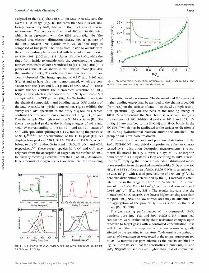
The specific surface area and pore size distribution of theSnO2 NS@SiC NF hierarchical composite were further charac-terized by N2 adsorption–desorption measurements. The iso-therm illustrated in Fig. 6 reveals a typical IV adsorptionbranches with a H3 hysteresis loop according to IUPAC classi-fication,37 implying that there are abundant slit-shaped meso-pores resulted from the packed nanosheet-like SnO2 on the SiCNFs. The BET surface area of SnO2 NS@SiC NFs is calculated tobe 28.6 m2 g�1 with a total pore volume of 0.04 cm3 g�1. Thepore size distribution determined by the BJH method is calcu-lated to be in the range of 0.2–15 nm. While the BET surfacearea of pure SnO2 NSs is 14.1 m2 g�1 with a total pore volume of0.016 cm3 g�1 (Fig. S3, ESI†). The results indicate that thehierarchical SnO2 NS@SiC NFs have a higher sensing area thanthe pure SnO2 NSs. The low surface area may be attributed tothe aggregation of the pure SnO2 NSs as shown in the SEMimage (Fig. S4, ESI†).
The gas sensing performances of the commercial SnO2
powders, pure SnO2 NSs and SnO2 NS@SiC NF hierarchicalcomposites were evaluated by their resistance changes uponexposure to target gases with a controlled concentration. It iswell known that the response of the gas sensor is greatlyaffected by the operating temperature. To determine the optimumone, all of the gas sensors were tested at the temperature from 200to 500 1C towards 100 ppm ethanol as the results exhibited inFig. 7a. It can be seen that the sensitivities of pure SnO2 NS andSnO2 NS@SiC NF sensors are higher than that of commercial
Fig. 5 XPS analysis of SnO2 NS@SiC NFs: (a) survey spectrum; (b) Sn 3d;(c) O 1s and (d) Si 2p.
Fig. 6 N2 adsorption–desorption isotherm of SnO2 NS@SiC NFs. Theinset is the corresponding pore size distribution.
Journal of Materials Chemistry C Paper
Publ
ishe
d on
30
Nov
embe
r 20
15. D
ownl
oade
d by
Bei
jing
Uni
vers
ity o
f C
hem
ical
Tec
hnol
ogy
on 1
3/03
/201
6 08
:58:
53.
View Article Online

300 | J. Mater. Chem. C, 2016, 4, 295--304 This journal is©The Royal Society of Chemistry 2016
SnO2 powders, indicating the advantages of SnO2 NSs for gassensing. However, almost a negligible signal was obtained withthe presence of 100 ppm ethanol gas for pure SiC NF sensors from200 to 500 1C (Fig. S5, ESI†), indicating the poor sensing perfor-mance of SiC NFs for ethanol gas detection. Obviously, along withthe rising operating temperature, the sensitivities (S = Ra/Rg) of thethree sensors increase initially to the highest value and then dropwith a further increase of the temperature. The optimum tem-perature is found to be 350 1C for the sensors based on pureSnO2 NSs and SnO2 NS@SiC NFs. At relatively low temperature(o350 1C), the low sensitivity can be attributed to the insufficientenergy to overcome the reaction activation energy barrier.38 At thetemperature higher than 350 1C, the reduction in sensitivity maybe due to the difficulty in exothermic gas adsorption.39 It has beendemonstrated that the interaction between gas molecules andSnO2 surfaces is an exothermic reaction.40 The accumulation of alarge amount of heat energy on the SnO2 surface leads to the fastdesorption of gas molecules before reacting with the oxygenspecies on the SnO2 surface at higher temperature,34 resultingin an obvious drop in sensor response. The higher sensitivity ofthe SnO2 NS@SiC NF sensor than that of the pure SnO2 NS sensoris contributed to the heterojunction effect of SnO2 and SiC, thespecific hierarchical structure and the vertical growth of SnO2 NSs.
Excitingly, the SnO2 NS@SiC NF sensor still presents a highsensitivity of 7.2 (vs. 3.1 for the pure SnO2 NS sensor) even at thehigh temperature of 500 1C, confirming the great potential of SnO2
NS@SiC NFs for application in high temperature environments.An additional reason may be attributed to the high thermalconductivity of SiC, which can rapidly remove part of heat energyto keep the redox reaction on the SnO2 surface.
Fig. 7b shows the dynamic sensing responses of the sensorsbased on pure SnO2 NSs and SnO2 NS@SiC NFs toward variousethanol concentrations (10–500 ppm) at the optimized tempera-ture of 350 1C. It can be found that the sensitivities of both thesensors are highly dependent on the ethanol concentration in themeasurement range. As the sensitivity–concentration plot shownin Fig. S6 (ESI†), the sensitivities of the two sensors almost increaselinearly with the increment of ethanol concentration, particularlyat the concentration lower than 100 ppm. The successive responsechange exhibits the consecutive detection capability of the sensorsto target gases even at high temperature. Moreover, the resistanceof the sensor goes back to almost the same value when 10 ppm ofethanol was injected into the chamber again. The result suggeststhe excellent reproducibility of the SnO2 NS@SiC NF sensor.
Similar orderliness between sensitivity and concentrationcan also be obtained at the elevated temperature of 500 1C
Fig. 7 (a) Sensor responses of the pure SnO2 NSs and SnO2 NS@SiC NFs to 100 ppm ethanol at different operating temperatures; (b) dynamic sensingresponse of pure SnO2 NSs and SnO2 NS@SiC NFs toward various ethanol concentrations at 350 1C; (c) sensing reproducibility of the SnO2 NS@SiC NFhierarchical composite sensor and (d) comparison of the response time and recovery time between pure SnO2 NSs and SnO2 NS@SiC NFs; ethanolconcentration is 100 ppm; operating temperature is 500 1C. Response and recovery time were defined as the time needed to reach 90% of the totalsignal change, respectively.
Paper Journal of Materials Chemistry C
Publ
ishe
d on
30
Nov
embe
r 20
15. D
ownl
oade
d by
Bei
jing
Uni
vers
ity o
f C
hem
ical
Tec
hnol
ogy
on 1
3/03
/201
6 08
:58:
53.
View Article Online

This journal is©The Royal Society of Chemistry 2016 J. Mater. Chem. C, 2016, 4, 295--304 | 301
(Fig. S7, ESI†), implying the outstanding sensing behavior athigh temperature. The sensitivities of the SnO2 NS@SiC NFsensor are from 3.9 to 63.2 for 5–500 ppm ethanol, which ishigher than that of the pure SnO2 NS sensor (1.8–28.4) at thesame concentration, further demonstrating the superior sen-sing performance of SnO2 NS@SiC NFs. Even when the ethanolconcentration is as low as 500 ppb, the sensitivity of the SnO2
NS@SiC NF sensor can reach 1.2 (Fig. S8, ESI†), indicating thelow detect limit of the sensor.
To investigate the reproducibility of the SnO2 NS@SiC NFsensor, the same sensor was exposed to ethanol with the sameconcentration for 5 cycles (Fig. 7c). Evidently, consistent sensingresponses with excellent recovery characteristics were observedin comparison to the usual significant baseline drift for the SnO2
sensor,1 indicating the excellent reproducibility of our sensor.The response and recovery times (tres and trecov), which areaccordingly defined as the time to achieve 90% of the totalresistance change in the case of adsorption (reaching the max-imum response) and desorption (back to the original resistance),are also important characteristic parameters for gas sensors. Asshown in Fig. 7d, the tres and trecov of the SnO2 NS@SiC NFsensor are respectively found to be 4 and 6 s at 500 1C, which aremuch faster than those of the SnO2 NS sensor (7 and 30 s,respectively) and commercial SnO2 powders (11 s and 29 s,respectively, Fig. S9, ESI†). Even at the temperature of 350 1C,the SnO2 NS@SiC NF sensor show tres of 6 s and trecov of 35 s,corresponding to 1.6 and 5 times faster than those of the pureSnO2 NS sensor (Fig. S10, ESI†). Very recently, the hierarchical Zndoped SnO2 nanosheets were reported to present a slow tres of14 s toward 100 ppm ethanol at 320 1C.41 Such rapid responseand recovery speeds of our sensor are ascribed to the specific
hierarchical architectures and the vertically ultrathin nanosheetmorphology, which can maximize the contact area between thegas molecules and the sensor to facilitate the adsorption anddesorption of the ethanol molecular. In the case of pure SnO2
NSs, it can be seen that the sphere-like SnO2 NSs obviouslyaggregate together and some SnO2 NSs are covered by nanosheets(Fig. S4, ESI†), which results in the low effective reactive area andthe resort of the gas.
The advantages of the hierarchical structure to acceleratethe adsorption and desorption of target gases were also validatedby measuring the response/recovery characteristics of the SnO2
NS@SiC NF sensor towards various gases (e.g., reducing gases,methanol, isopropanol, acetone, hydrogen and xylene) as illu-strated in Fig. 8. It can be seen that all of the tres values are lessthan 5 s (for methanol, tres = 3 s; isopropanol, tres = 3 s; acetone,tres = 4 s; hydrogen, tres = 1 s; xylene, tres = 5 s), while the trecov arein the range of 9–15 s (for methanol, trecov = 9 s; isopropanol,trecov = 13 s; acetone, trecov = 7 s; hydrogen, trecov = 15 s; xylene,trecov = 10 s). In addition, the response and recovery speeds ofour sensor are among the fastest in contrast to the reportedSnO2-based gas sensors recently (Table S1, ESI†), further demon-strating the excellent response/recovery behavior of our SnO2
NS@SiC NF gas sensor. Fig. 8f shows the sensing selectivity ofthe SnO2 NS@SiC NF sensor upon exposure to various gases,including ethanol, methanol, isopropanol, acetone, hydrogenand xylene. Among the investigated gases, the sensor shows thestrongest response toward ethanol, which is 1.6 times tohydrogen and 2–4 times to other gases. The result suggeststhe prepared SnO2 NS@SiC NF sensor exhibits an ethanol sensingselectivity. The different adsorption abilities and activities ofdifferent target gases on the SnO2 NS@SiC NFs are different at a
Fig. 8 Ultrafast response/recovery performance of the SnO2 NS@SiC NF hierarchical composite sensor toward: (a) methanol; (b) isopropanol; (c)acetone; (d) hydrogen and (e) xylene; (f) is the comparison of the sensitivity among various gases, implying the high selectivity of the sensor towardethanol. The gas concentration is 100 ppm and the operating temperature is 500 1C.
Journal of Materials Chemistry C Paper
Publ
ishe
d on
30
Nov
embe
r 20
15. D
ownl
oade
d by
Bei
jing
Uni
vers
ity o
f C
hem
ical
Tec
hnol
ogy
on 1
3/03
/201
6 08
:58:
53.
View Article Online

302 | J. Mater. Chem. C, 2016, 4, 295--304 This journal is©The Royal Society of Chemistry 2016
given temperature, which may result in the superior sensingselectivity of SnO2 NS@SiC NFs.18
The sensing performances of the SnO2 NS@SiC NF sensortowards ethanol were measured after 30 and 60 days, respec-tively, to investigate the long-term stability of the sensor. Asshown in Fig. 9, the gas sensor displays a constant response/recovery behavior as well as the sensitivity toward ethanol after30 and 60 days, demonstrating the superior long-term stabilityof SnO2 NS@SiC NFs.
Collectively, the SnO2 NS@SiC NF sensor shows high sensitivity,excellent reproducibility, good sensing selectivity, outstandinglong-term stability and particularly ultrafast response/recoveryspeed toward ethanol, even at high temperature. A proposedsensing mechanism is illustrated in Fig. 10. Firstly, the ultrathinSnO2 NSs with a high surface-to-volume ratio were verticallygrown on the SiC NFs, supplying a three-dimensional attacking
possibility for the target gases. The target gases can react withoxygen species on the SnO2 NSs from the discretional direction.Benefiting from the hierarchical architectures, each of the SnO2
NSs on the SiC NFs contributes to the sensing sites, while thepure SnO2 NSs have a relatively low sensing area because of theiraggregation. Secondly, thanks to the in situ fabrication process asillustrated in Scheme 1, the SiC NFs and SnO2 NSs are tightlyconnected to form a heterojunction. And the potential barrierbetween SnO2 and SiC is very low since the work functionof SnO2 (4.5–4.9 eV)11,42 is just a little smaller than that of SiC(4.5–5.2 eV).43,44 These two reasons make it easy for the electrontransfer from the CB of SiC to the CB of SnO2, and simulta-neously the holes on the valence band (VB) of SnO2 can travel tothe VB of SiC. At the same time, a built-in potential barrierbetween SiC NFs and SnO2 NSs is established. The efficientcharge separation extends the lifetime of the charge carriers,promoting the charge transfer efficiency of the interface toSnO2.45 Thirdly, the ultrathin SnO2 NSs are tightly connectedtogether forming a homojunction potential barrier betweenSnO2 NSs. Blocked by the built-in potential barrier and homo-junction potential barrier, the electron transporting in thesystem is greatly restricted. Thereupon, more oxygen speciesare absorbed on the surface of SnO2 NSs (in SnO2 NS@SiC NFs)due to the extra electrons on SnO2 NSs, which are provided bythe migration of electrons at the heterojunction interface. Forreducing target gases (denoted as R, electron donor), more gasmolecules can be oxidized by the oxygen species (R + O� -
RO + e�). Thus larger amounts of electrons will be releasedback to SnO2 NSs, further decreasing the resistance of the SnO2
NS@SiC NF sensor. It has also been demonstrated that theresistance is exponentially proportional to the effective barrierheight, R = R0 exp(qV/kT), where R and R0 are accordingly thereal and initial resistances of the sensor, and qV is the potentialbarrier height.46 Obviously, the reaction between the targetgases and the sensor will change the two potentials barriersin the sensor system, further leading to a significant change inthe resistance of the sensor. As a consequence, the SnO2 NS@SiCNF sensor shows a higher response than the SnO2 NS sensor.
Although a relatively fast response/recovery speed can beobtained at higher temperature due to the more energy toaccelerate the desorption of gases and the reaction betweentarget gases and the sensing materials, that is not the mainreason in the case of our SnO2 NS@SiC NF sensor. In fact, theresponse/recovery speed of the SnO2 NS@SiC NF sensor ismuch faster than those of the commercial SnO2 powders andthe pure SnO2 NS sensor at the same operating temperature. Itis reported that 3C-SiC owns high electron mobility due to theenhanced oxygen concentration accumulated at the crystaldefects.47–49 Therefore, the quasi-one-dimensional SiC NF corewith high aspect ratios can supply a continuous transportpathway for the fast charge transfer.27,50 Moreover, the accessibleelectron transfer between the SnO2 NSs (contacted closely witheach other as shown in Fig. 3c) and the heterojunction ofSnO2–SiC accelerate the electron transport in the sensor. Theselead to the faster response rate of the SnO2 NS@SiC NF sensor.In the case of the desorption process, the resultant gases can
Fig. 9 The response/recovery behavior of the hierarchical SnO2 NS@SiCNF sensor after 30 and 60 days, implying the superior long-term stability ofthe sensor.
Fig. 10 Proposed sensing mechanism for the high sensitivity and ultrafastresponse/recovery rate of the SnO2 NS@SiC NFs.
Paper Journal of Materials Chemistry C
Publ
ishe
d on
30
Nov
embe
r 20
15. D
ownl
oade
d by
Bei
jing
Uni
vers
ity o
f C
hem
ical
Tec
hnol
ogy
on 1
3/03
/201
6 08
:58:
53.
View Article Online

This journal is©The Royal Society of Chemistry 2016 J. Mater. Chem. C, 2016, 4, 295--304 | 303
leave the surface of SnO2 NS@SiC NFs almost without anyhindrance due to the hierarchical structure of vertical SnO2
NSs on SiC NFs. It has been demonstrated that the hierarchicalarchitectures can provide a method to maximize the interfacialarea for effective electron transfer and gas diffusion, thus lead-ing to fast sensing response and recovery of sensors.51,52 How-ever, the gases are detained by the aggregated SnO2 of the pureSnO2 NS sensor, which results in its slower recovery rate. Takentogether, the higher response and the fast response/recovery rateof the SnO2 NS@SiC NF sensor are attributed to the accessibleelectron transfer at the interface of the SnO2–SiC heterojuctionas well as the specific hierarchical architectures of verticalultrathin SnO2 NS@SiC NFs.
Conclusions
In conclusion, vertically ultrathin SnO2 NSs were in situ grownon the quasi-one-dimensional SiC NFs forming a hierarchicalarchitecture via a simple hydrothermal method. Comparedwith commercial SnO2 powders and pure SnO2 NSs, the SnO2
NS@SiC NF hierarchical composite exhibited a superior gassensing performance including high sensitivity, excellent repro-ducibility, outstanding sensing selectivity, long-term stabilityand particularly ultrafast response/recovery rate toward ethanolamong the target gases (ethanol, methanol, isopropanol, acetone,hydrogen and xylene), even at high temperature (500 1C). Such asuperior sensing performance is attributed to the synergic effectof SnO2–SiC heterojunction, the hierarchical structure as well asthe vertical growth of the ultrathin nanosheet morphology. Thiswork may be directional to design high performance gas sensorsfor application in harsh environments.
Acknowledgements
This work was financially supported by National Natural ScienceFoundation of China (51173202, 51203182), Hunan ProvincialNatural Science Foundation of China (13JJ4009), State Key Labora-tory of Advanced Technology for Materials Synthesis and Proces-sing (Wuhan University of Technology) (2014-KF-10), the State KeyLaboratory of Refractories and Metallurgy, Wuhan University ofScience and Technology (G201501) and Research Project ofNational University of Defense Technology (JC13-01-05). Thiswork was also supported by Aid program for Science andTechnology Innovative Research Team in Higher EducationalInstitutions of Hunan Province and Aid Program for InnovativeGroup of National University of Defense Technology.
Notes and references
1 A. Kaushik, R. Kumar, S. K. Arya, M. Nair, B. D. Malhotraand S. Bhansali, Chem. Rev., 2015, 115, 4571–4606.
2 M. W. G. Hoffmann, L. Mayrhofer, O. Casals, L. Caccamo,F. Hernandez-Ramirez, G. Lilienkamp, W. Daum, M. Moseler,A. Waag, H. Shen and J. D. Prades, Adv. Mater., 2014, 26,8017–8022.
3 S. M. Majhi, P. Rai and Y. T. Yu, ACS Appl. Mater. Interfaces,2015, 7, 9462–9468.
4 S. Singkammo, A. Wisitsoraat, C. Sriprachuabwong,A. Tuantranont, S. Phanichphant and C. Liewhiran, ACSAppl. Mater. Interfaces, 2015, 7, 3077–3092.
5 A. Das, V. Bonu, A. K. Prasad, D. Panda, S. Dhara andA. K. Tyagi, J. Mater. Chem. C, 2014, 2, 164–171.
6 J. H. Lee, A. Katoch, S. W. Choi, J. H. Kim, H. W. Kim andS. S. Kim, ACS Appl. Mater. Interfaces, 2015, 7, 3101–3109.
7 Z. Zhang, X. Zou, L. Xu, L. Liao, W. Liu, J. Ho, X. Xiao,C. Jiang and J. Li, Nanoscale, 2015, 7, 10078–10084.
8 G. Lu, L. E. Ocola and J. Chen, Adv. Mater., 2009, 21,2487–2491.
9 S. Xu, Y. Yang, H. Y. Wu, C. Jiang, L. Q. Jing and K. Y. Shi,J. Inorg. Mater., 2013, 28, 584–588.
10 S. H. Jeong, S. Kim, J. Cha, M. S. Son, S. H. Park, H. Y. Kim,M. H. Cho, M. H. Whangbo, K. H. Yoo and S. J. Kim, NanoLett., 2013, 13, 5938–5943.
11 L. Xu, R. Xing, J. Song and H. Song, J. Mater. Chem. C, 2013,1, 2174–2182.
12 S. Cui, Z. Wen, X. Huang, J. Chang and J. Chen, Small, 2015,11, 2305–2313.
13 H. Wang, K. Dou, W. Y. Teoh, Y. Zhan, T. F. Hung, F. Zhang,J. Xu, R. Zhang and A. L. Rogach, Adv. Funct. Mater., 2013,23, 4847–4853.
14 X. Chen, Z. Guo, W. H. Xu, H. B. Yao, M. Q. Li, J. H. Liu,X. J. Huang and S. H. Yu, Adv. Funct. Mater., 2011, 21,2049–2056.
15 H. R. Kim, A. H. I. D. Kim, N. Barsan, U. Weimar andJ. H. Lee, Adv. Funct. Mater., 2011, 21, 4456–4463.
16 J. S. Lee, O. S. Kwon, S. J. Park, E. Y. Park, S. A. You, H. Yoonand J. Jang, ACS Nano, 2011, 5, 7992–8001.
17 J. Zhang, S. Wang, M. Xu, Y. Wang, H. Xia, S. Zhang, X. Guoand S. Wu, J. Phys. Chem. C, 2009, 113, 1662–1665.
18 L. Li, S. He, M. Liu, C. Zhang and W. Chen, Anal. Chem.,2015, 87, 1638–1645.
19 H. Liu, M. Li, O. Voznyy, L. Hu, Q. Fu, D. Zhou,Z. Xia, E. H. Sargent and J. Tang, Adv. Mater., 2014, 26,2718–2724.
20 Y. Liu, J. Parisi, X. Sun and Y. Lei, J. Mater. Chem. A, 2014, 2,9919–9943.
21 M. T. Soo, K. Y. Cheong and A. F. M. Noor, Sens. Actuators, B,2010, 151, 39–55.
22 P. Tsiakarasa and A. Demin, J. Power Sources, 2001, 102,210–217.
23 S. D. Nobrega, M. V. Galesco, K. Giron, D. Z. de Florio,M. C. Steil, S. Georges and F. C. Fonseca, J. Power Sources,2012, 213, 156–159.
24 L. Li, M. Liu, S. He and W. Chen, Anal. Chem., 2014, 86,7996–8002.
25 B. Wang, Y. Wang, Y. Lei, N. Wu, Y. Gou, C. Han andD. Fang, J. Mater. Chem. A, 2014, 2, 20873–20881.
26 J. Chen, J. Zhang, M. Wang and Y. Li, Sens. Actuators, B,2014, 201, 402–406.
27 M. Kim, I. Oh and J. Kim, J. Power Sources, 2015, 282,277–285.
Journal of Materials Chemistry C Paper
Publ
ishe
d on
30
Nov
embe
r 20
15. D
ownl
oade
d by
Bei
jing
Uni
vers
ity o
f C
hem
ical
Tec
hnol
ogy
on 1
3/03
/201
6 08
:58:
53.
View Article Online

304 | J. Mater. Chem. C, 2016, 4, 295--304 This journal is©The Royal Society of Chemistry 2016
28 A. Karakuscu, A. Ponzoni, E. Comini, G. Sberveglieri andC. Vakifahmetoglu, Int. J. Appl. Ceram. Technol., 2014, 11,851–857.
29 S. Ding, J. S. Chen and X. W. (David). Lou, Adv. Funct. Mater.,2011, 21, 4120–4125.
30 S. W. Choi, A. Katoch, G. J. Sun, P. Wu and S. S. Kim,J. Mater. Chem. C, 2013, 1, 2834–2841.
31 Y. Bing, Y. Zeng, C. Liu, L. Qiao, B. Zou and W. Zheng,Nanoscale, 2015, 7, 3276–3284.
32 C. Wang, G. Du, K. Ståhl, H. Huang, Y. Zhong and J. Z. Jiang,J. Phys. Chem. C, 2012, 116, 4000–4011.
33 W. Li, S. Ma, Y. Li, G. Yang, Y. Mao, J. Luo, D. Gengzang,X. Xu and S. Yan, Sens. Actuators, B, 2015, 211, 392–402.
34 C. Dong, X. Liu, X. Xiao, G. Chen, Y. Wang and I. Djerdj,J. Mater. Chem. A, 2014, 2, 20089–20095.
35 W. Ke, G. Fang, Q. Liu, L. Xiong, P. Qin, H. Tao, J. Wang,H. Lei, B. Li, J. Wan, G. Yang and Y. Yan, J. Am. Chem. Soc.,2015, 137, 6730–6733.
36 Y. Wang, B. Wang, Y. Lei, N. Wu, C. Han, Y. Gou andD. Fang, Appl. Surf. Sci., 2015, 335, 208–212.
37 K. S. W. Sing, D. H. Everett, R. A. W. Haul, L. Moscou,R. A. Pierotti, J. Rouquerol and T. Siemieniewska, Pure Appl.Chem., 1985, 57, 603–619.
38 B. Mondal, B. Basumatari, J. Das, C. Roychaudhury, H. Sahaand N. Mukherjee, Sens. Actuators, B, 2014, 194, 389–396.
39 Y. Wang, Y. Wang, J. Cao, F. Kong, H. Xia, J. Zhang, B. Zhu,S. Wang and S. Wu, Sens. Actuators, B, 2008, 131, 183–189.
40 Y. Chen, X. Wang, C. Shi, L. Li, H. Qin and J. Hu, Sens.Actuators, B, 2015, 220, 279–287.
41 Q. Zhao, D. Ju, X. Deng, J. Huang, B. Cao and X. Xu, Sci. Rep.,2015, 5, 7874.
42 M. Punginsang, A. Wisitsoraat, A. Tuantranont, S. Phanichphantand C. Liewhiran, Sens. Actuators, B, 2015, 210, 589–601.
43 X. Zhang, Y. Chen, W. Liu, W. Xue, J. Li and Z. Xie, J. Mater.Chem. C, 2013, 1, 6479–6486.
44 Y. Yang, G. Meng, X. Liu, L. Zhang, Z. Hu, C. He and Y. Hu,J. Phys. Chem. C, 2008, 112, 20126–20130.
45 G. Lu, J. Xu, J. Sun, Y. Yu, Y. Zhang and F. Liu, Sens.Actuators, B, 2012, 162, 82–88.
46 J. Liu, S. Gong, Q. Fu, Y. Wang, L. Quan and Z. Deng,Sens. Actuators, B, 2010, 150, 330–338.
47 N. Yang, H. Zhuang, R. Hoffmann, W. Smirnov,J. Hees, X. Jiang and C. E. Nebel, Anal. Chem., 2011, 83,5827–5830.
48 K. Rogdakis, M. Bescond, E. Bano and K. Zekentes, Nano-technology, 2007, 18, 475715.
49 M. Kim, I. Oh and J. Kim, J. Mater. Chem. A, 2015, 3,3944–3951.
50 C. Han, Y. Wang, Y. Lei, B. Wang, N. Wu, Q. Shi and Q. Li,Nano Res., 2015, 8, 1199–1209.
51 D. R. Miller, S. A. Akbar and P. A. Morris, Sens. Actuators, B,2014, 204, 250–272.
52 S. Park, H. Ko, S. Kim and C. Lee, ACS Appl. Mater. Interfaces,2014, 6, 9595–9600.
Paper Journal of Materials Chemistry C
Publ
ishe
d on
30
Nov
embe
r 20
15. D
ownl
oade
d by
Bei
jing
Uni
vers
ity o
f C
hem
ical
Tec
hnol
ogy
on 1
3/03
/201
6 08
:58:
53.
View Article Online