journal of microscopic equipment, methods and … · journal of microscopic equipment, methods and...
TRANSCRIPT

^ E21954F
MICROSCOPICA ACTA JOURNAL OF MICROSCOPIC EQUIPMENT,
METHODS AND APPLICATIONS
E D I T O R S
R. D. Allen, Hanover/USA-W. Boguth, Basel-L. Jenny, Basel-O. Johari, Chicago E. Kellenberger, Basel • H. Rohr, Basel • W. Stockem, Bonn
NUMBER 1 . VOLUME 81 • SEPTEMBER 1978
S. HIRZEL VERLAG STUTTGART
Microsc Acta ISSN 0044-376 X

MICROSCOPICA ACTA Journal of microscopic equipment, methods and applications
formerly
Zeitschrift für wissenschaftliche Mikroskopie und mikroskopische Technik
Editors: Prof. Dr. R. D. Allen, Prof. Dr. W. Boguth, Prof. Dr. L. Jenny, Dr. O. Johari, Prof. Dr. E. Kellenberger, Prof. Dr. H. Rohr, Prof. Dr. W. Stockem
Co-Editiorial Board
L . Albert, Karlsruhe • O. von Deimling, Freiburg i . Br. • D . Gerlach, Erlangen • H . Hasel
mann, Tübingen • H . Haug, Lübeck • L . Hottinger, Basel • G . Kiefer, Freiburg i. Br. • A .
Läuchli , Hannover • K . Lickfeld, Essen • M . - T h . Mackowsky, Essen • K . Michel, Aalen •
H . Mörte l , Erlangen • J . S. Ploem, Leiden • M . Pluta, Warszawa • H . Raith, Dortmund • A .
Schaefer, Heerbrugg • K l . P. SchindT, Wien • F . Thon, Berlin • E . Treiber, Stockholm
M I C R O S C O P I A A C T A publishes reviews, original papers, reports and references to literature covering the whole field of light and electron microscopy with regard to the aspect of micro-scopy technique.
MICSROSCOPIA A C T A veröffentl ichen Übersichtsbeiträge, Originalarbeiten, Berichte und
Literaturhinweise, die das Gebiet der Lichtmikroskopie und der Elektronenmikroskopie unter
dem Gesichtspunkt der mikroskopischen Technik behandeln.
Contributions will be accepted in English, Ger
man or French and should be submitted to the
Acting Etidor:
Manuskripte k ö n n e n in deutscher, englischer
oder französicher Sprache abgefaßt sein. Sie
sind bei der Redaktion einzureichen:
M I C R O S C O P I A A C T A
Prof. Dr. Louis Jenny, Bäumlihofstr. 375
CH-4125 Riehen/Switzerland
Tel. Private: (0 61) 49 59 69
Institute: (0 61) 43 44 15
Terms of delivery
The Journal is published in issues combined to a volume of approximately 450 pages. Sub-
scription rate D M 145,— per volume. Orders can be placed with any bookseller or the pub-
lisher.
Bezugsbedingungen
Die Zeitschrift erscheint in einzelnen Heften, die zu B ä n d e n mit etwa 450 Seiten zusammen
gestellt werden. Preis im Abonnement je Band D M 145,—.
Bestellungen nimmt jede Buchhandlung im In- und Ausland und der Verlag entgegen.

MICROSCOPICA ACTA JOURNAL OF MICROSCOPIC EQUIPMENT,
METHODS AND APPLICATIONS
6-E D I T O R S
R. D. Allen, Hanover/USA-W. Boguth, Basel-L. Jenny, Basel-O. Johari, Chicago E. Kellenberger, Basel • H. Rohr, Basel • W. Stockem, Bonn
Volume 81 — 1979 — Band 81
S. HIRZEL VERLAG STUTTGART
Microsc. Acta ISSN 0044-376 X

MICROSCOPICA ACTA Journal of microscopic equipment, methods and applications
formerly
Zeitschrift für wissenschaftliche Mikroskopie und mikroskopische Technik
Editors: Prof. Dr. R. D. Allen, Prof. Dr. W. Boguth, Prof. Dr. L. Jenny, Dr. O. Johari, Prof. Dr. E. Kellenberger, Prof. Dr. H. Rohr, Prof. Dr. W. Stockem
Co-Editiorial Board
L . Albert, Karlsruhe • O. von Deimling, Freiburg i. Br. • D . Gerlach, Erlangen • H . Hasel
mann, Tübingen • H . Haug, Lübeck • L . Hottinger, Basel • G . Kiefer, Freiburg i. Br. • A .
Läuchli, Hannover • K . Lickfeld, Essen • M . - T h . Mackowsky, Essen • K. Michel, Aalen •
H . Mörtel , Erlangen • J . S. Ploem, Leiden • M . Pluta, Warszawa • H . Raith, Dortmund • A .
Schaefer, Heerbrugg • K l . P. Schindl, Wien • F . Thon, Berlin • E . Treiber, Stockholm •
D . Wittekind, Freiburg i. Br.
M I C R O S C O P I C A A C T A publishes reviews, original papers, reports and references to literature
covering the whole fleld of light and electron microscopy with regard to the aspect of micro-
scopical technique.
M I C R O S C O P I C A A C T A veröffentlichen Übersichtsbeiträge, Originalarbeiten, Berichte und
Literaturhinweise, die das Gebiet der Lichtmikroskopie und der Elektronenmikroskopie unter
dem Gesichtspunkt der mikroskopischen Technik behandeln.
Contributions will be aeeepted in English, Ger
man or French and should be submitted to the
Acting Editor:
Manuskripte können in deutscher, englischer oder französischer Sprache abgefaßt sein. Sie sind bei der Redaktion einzureichen:
M I C R O S C O P I C A A C T A
Prof. Dr. Louis Jenny, Bäumlihofstr. 375
CH-4125 Riehen/Switzerland
Tel. Private: (0 61) 49 59 69
Institute: (0 61) 43 44 15
The issues of Volume 80 appeared:
Number 1 September 1978 Number 2 November 1978 Number 3 January 1979 Number 4 March 1979 Number 5 May 1979
© S. Hirzel Verlag Stuttgart 1979

A. Authors of papers
Adams , Derek, see W i l l i a m s , D a v i d
Agrosk in , L . S., see Pevzner, L . Z .
Ä k e r m a n , K a r l , E . 0 . : Measurements of m e m b r a n e p o t e n t i a l s u s i n g t h e dye s a f r a n i n e . 147
Bestimmungen von Membranpotent ia len mit H i l f e von Safranin
A z z a m , R . M . A . : O p t i c a l d e t e c t i o n of c e l l - s u r f a c e changes a s s o c i a t e d w i t h m a l i g n a n t t r a n s f o r m a t i o n s i n v i t r o 313
Optische m-v/'/ro-Feststellung von Z e l l o b e r f l ä c h e n ä n d e r u n g e n in Verb indung mit bös artigen Transformationen
Bezler, Hans f, see Leder , O r t w i n
Bhattacharyya, Tapan K u m a r : A dißerential s t a i n i n g t e c h n i q u e f o r v e r t e b r a t e h i s t o l o g y ( S h o r t c o m m u n i c a t i o n ) 299
Une methode de colorat ion differentielle pour l 'histologie des Vertebres
Boer, H e i n , and Woul te r H . van Eek: The p e n e t r a t i o n of t h e e m b e d d i n g m e d i u m m e t h y l m e t h a c r y l a t e i n u n d e c a l c i f i e d bone 181
Das Eindr ingen von Methylmethacryla t als Einbettungsmittel für unentkalkte K n o
chen
Borovikov, Y u r i i S., and Na ta l i a A . Chernogriadskaia: Studies o n c o n f o r m a t i o n a l changes i n F - a c t i n of g l y c e r i n a t e d muscle f i b e r s d u r i n g r e l a x a t i o n by means of p o l a r i z e d u l t r a v i o l e t fluorescence m i c r o s c o p y 383
K o n f o r m a t i o n s ä n d e r u n g e n i m F - A k t i n i m V e r l a u f des Erschlaffens glyzerinisierter Muskelfasern. Untersuchungen mit H i l f e von Fluoreszenzmikroskopie i m polarisierten U V
Chernogriadskaia, N a t a l i a A . , see Borov ikov , Y u r i i S.
C h u n , M o o n j i n , see Sernetz, Manf red
Co l l in s , Barbara A n n , and E d w a r d F o r d M a c N i c h o l , jr.: L o n g t e r m fixation f o r h i s t o l o g -i c a l studies ( S h o r t c o m m u n i c a t i o n ) 155
Langzeitf ixation für histologische Untersuchungen

I V Authors of papers
C o l l i n s , Barbara A n n , and E d w a r d F o r d M a c N i c h o l , jr.: S e c t i o n i n g of E p o n b l o c k s i n t h e 2 0 am t o 6 0 um ränge f o r h i s t o l o g i c a l studies ( S h o r t c o m m u n i c a t i o n ) . . . . 227
20—60 um dicke Schnitte von E p o n - B l ö c k e n für histologische Untersuchungen
C o l m a n , Ond ina D . , and Juan C . Stockert: O b s e r v a t i o n s o n t h e n u c l e o l a r s t a i n i n g by e t h a n o l i c p h o s p h o t u n g s t i c a c i d ( S h o r t c o m m u n i c a t i o n ) 27
Beobachtung ü b e r die N u k l e o l a r f ä r b u n g durch ä thy l a lkoho l i s che Phosphorwol f rams ä u r e
Cremer , Chr is toph, and Thomas Cremer : C o n s i d e r a t i o n s o n a l a s e r - s c a n n i n g - m i c r o s c o p e w i t h h i g h r e s o l u t i o n a n d d e p t h of field 31
Ü b e r l e g u n g e n zu einem Laser -Scanning-Mikroskop mit hoher A u f l ö s u n g und Schär fentiefe
Cremer , Thomas, see Cremer , Chr i s toph
Dewar , Catherine L . , and Michae l W . W o l o w y k : S c a n n i n g e l e c t r o n m i c r o s c o p y of b l o o d c e l l s 209
L 'examen de leukocytes et d'erythrocytes au microscope ä balayage
D i m o c k , R o n a l d V . , jr., see Hazen , Ter ry
Dut t , M i h i r K . : C y t o c h e m i c a l s p e c i f i c i t y of a c r i d i n e r e d t o w a r d s R N A a n d d e p o l y m e r i s e d D N A 189 Cytochemische Spezifität von A k r i d i n r o t g e g e n ü b e r R N S und depolymerisierter D N S
Dut t , M i h i r K . : M o d i f i e d F e u l g e n s t a i n i n g of D N A w i t h aqueous S o l u t i o n of p i n a c y a n o l 195
Modif iz ier te F e u l g e n - F ä r b u n g für D N S mit wäss r ige r L ö s u n g von P inacyanol
Dut t , M i h i r K . : I n c r e a s e d s h e l f - l i f e a n d F e u l g e n s t a i n i n g i n t e n s i t y of a m o d i f i e d t r i c h l o r -a c e t i c a c i d - S c h i f f r e a g e n t 275
Verbesserte Hal tbarkei t und F e u l g e n - F ä r b u n g s i n t e n s i t ä t eines modifizierten Tr i ch lo r -ess igsäure-Schiff -Reagenz
Dut t , M i h i r K . : H o f f m a n ' s v i o l e t a n d D a h l i a as s p e c i f i c s t a i n s f o r a n i m a l chromosomes 293
HofTmans Vio le t t und D a h l i a als spezifische Farbstoffe für tierische Chromosomen
Dut t , M i h i r K . : S h e l f - l i f e of c i t r i c a c i d - t o l u i d i n e b l u e O-SO* a n d i t s i n f l u e n c e o n F e u l g e n s t a i n i n g 367
Z i t r o n e n s ä u r e - T o l u i d i n b l a u 0 - S O a : Lage r fäh igke i t und Einf luß auf die F e u l g e n - F ä r bung
Dutt , M i h i r K . : D e t e c t i o n of D N A i n m a m m a l i a n tissues f o l l o w i n g r e m o v a l of R N A w i t h c o l d p h o s p h o r i c a c i d 373
Nachweis von D N S i m Gewebe von S ä u g e r n nach Entfernung der R N S mit kalter P h o s p h o r s ä u r e

Authors of papers V
Dutt , M i h i r K . : F i x a t i o n of m a m m a l i a n tissues i n d i f f e r e n t fixatives a n d i t s i n f t u e n c e o n t h e s t a i n i n g w i t h m e t h y l g r e e n - p y r o n i n 379
Das F ix ie ren von S ä u g e r g e w e b e in verschiedenen F ixa t iven und deren Einf luß auf die F ä r b u n g mit M e t h y l g r ü n - P y r o n i n
Eek, Woul te r H van, see Boer, H e i n
Fr iebe, Bernd: U n t e r s u c h u n g e n zum S c h w e s t e r c h r o m a t i d e n a u s t a u s c h b e i Seeale c e r e a l e 159
Analys i s of sister chromatid exchange ( S C E ) in Seeale c e r e a l e
Gebhart , Josef, see Ro th , Chr i s ta
G lahn-Luf t , Birgi t , Peter Schley und R u d o l f Wassmuth: G e s c h l e c h t s d i f f e r e n z i e r u n g v o n neugeborenen K a n i n c h e n m i t H i l f e der K a r y o t y p a n a l y s e zu Versuchszwecken ( K u r z m i t t e i l u n g ) 289
Sexual differentiation of newborn rabbits wi th karyotype analysis for experimental use
Gundersen, Hans Jorgen G . : E s t i m a t o r s of t h e n u m b e r of o b j e c t s per a r e a u n b i a s e d by edge effects 107
A b s c h ä t z u n g s m e t h o d e n für die Objekt f lächendichte , frei von systematischen Fehle rn durch Randeffekte
Gup ta , A . K . , and K . Singh: I n f l u e n c e s of p r i m a r y c o m a o n p a r t i a l l y c o h e r e n t I m a g e s : T r u n c a t e d b a r t a r g e t s 265
D e r Einfluß p r i m ä r e r K o m a auf die part iel l k o h ä r e n t e A b b i l d u n g : Abgestufte periodische Strichraster
Habermalz , F r i t z : F a r b m e t r i s c h e U n t e r s u c h u n g e n über d i e m i t U m k e h r f a r b f i l m e n d a r s t e l l b a r e n F a r b e n 137
Colo r ime t r i ca l investigations of colors produced by color reversal films applied for photomicrography
Hanniba l -Fr iedr ich , Otto, see Sernetz, Manf red
Har tmann , Horst , und Klaus Paradies: E i n Präparationsverfahren für d i e A u f l i c h t fluo-r e s z e n z - M i k r o s k o p i e ( K u r z m i t t e i l u n g ) 407
A simple preparation technique for incident light fluorescence microscopy
Hazen, Ter ry C , G e r a l d Smith , and R o n a l d V . D imock , jr.: A m e t h o d f o r fixing a n d s t a i n i n g p e r i t r i c h e i l i a t e s 15
Eine Methode zum Fix ie ren und F ä r b e n von rundum bege iße l t en Ci l ia ten
H o l l ä n d e r , Hors tmar : I d e n t i f i c a t i o n of c y t o p l a s m i c l a m i n a r bodies i n n e u r o n s of t h e c a t l a t e r a l g e n i c u l a t e nucleus by phase c o n t r a s t m i c r o s c o p y 131
Phasenkontrastmikroskopischer Nachweis von cytoplasmatischen L a m e l l e n k ö r p e r c h e n in Nervenzel len des geniculatum laterale der Katze
Jacob, He lmut , Judit N o w a k , Peter Ve i th und H e i k o Wasmund : E l e k t r o n i s c h e D a t e n e r fassung u n d - V e r a r b e i t u n g i m O n - l i n e - B e t r i e b b e i der M i k r o s k o p - P h o t o m e t r i e fester, f o s s i l e r , o r g a n i s c h e r Stoffe 45
On-line data col lect ion and processing in connection with the microscope photometry of sol id, fossil , organic matter

V I Authors of papers
K e m a l i , M i l e n a : A p p l i c a t i o n of a r a p i d G o l g i m e t h o d a n d use o f p o t a s s i u m p e r m a n -g a n a t e i n t h e h i s t o l o g y of H y d r a 309
Anwendung einer modifizierten, raschen G o l g i - M e t h o d e und Verwendung von K a liumpermanganat in der His to logie von H y d r a
K r a u s , Herbert , see Schwarz, J ü r g e n
K u n t , Manf red , see Leder , O r t w i n
Leder , Or twin , Manf red K u n t und Hans B e z i e r t : P i l o t s t u d i e zur A u s w e r t u n g v o n V a g i n a l a b s t r i c h e n i n der z y t o l o g i s c h e n H o r m o n d i a g n o s t i k 281
The evaluation of vaginal smears in cytological hormone diagnosis: A pilot study
L ü t t g e , Bernhard, see M e n o l d , R ichard
M a c N i c h o l , E d w a r d F o r d , jr., see Co l l i n s , Barbara A n n
M a r s h a l l , P . N . : R e t i c u l a t i o n , p o l y c h r o m a s i a a n d s t i p p l i n g of e r y t h r o c y t e s ( R e v i e w ) . . 89
Ne tzb i ldung an, Polychromasie und T ü p f e l u n g von Ery throcy ten
M a r t i n , H . : Zum Gedächtnis a n P r o f . D r . A l f r e d G r a b n e r ( 2 0 . J a n . 1 8 9 6 — 2 8 . J a n . 1 9 7 8 ) 63
Mayf i e ld , C . L , see Polonenko, D . R .
M e n o l d , Richard , and Bernhard L ü t t g e : F r e e z e - e t c h i n g of d i s p e r s i o n s w i t h o u t c o n t a m i n a -t i o n of t h e f r a c t u r e faces 317
Kontaminationsfreies G e f r i e r ä t z e n von Dispersionen
M o r t , El izabeth , see W i l l i a m s , D a v i d
N o w a k , Judit, see Jacob, H e l m u t
Paradies, Klaus , see Har tmann , Hors t
Peters, J . H i n r i c h : Z e i t r a f f e r a n l a g e zur L e b e n d b e o b a c h t u n g v o n Z e l l e n i n der K u l t u r . . 217
Device for time lapse studies on l iv ing cells in culture
Pevzner, L . Z . , T . G . Raygorodskaya, and L . S. A g r o s k i n : Q u a n t i t a t i v e m i c r o s p e c t r a l e v a l u a t i o n of t h e r a t i o of a r g i n i n e - r i c h t o l y s i n e - r i c h histones i n n e u r o n s a n d n e u r o -g l i a l c e l l s 9
Eva lua t ion microspectrale quantitative du ratio des histones riches en arginine ou lysine dans les neurones et des cellules nevrologiques
Pietruschka, Fr icke , see Z i e r o l d , K a r l
Polonenko, D . R . , and C . I. Mayf i e ld : F l u o r e s c e n c e p r o b e s f o r use as s t a i n i n g agents i n s o i l 303
Fluoreszierende Stoffe als F ä r b e m i t t e l für Bodenproben
Raffler, Har tmut , see Schwarz, J ü r g e n

Authors of papers V I I
Raygorodskaya , T . G . , see Pevzner, L . Z .
R o t h , Chris ta , and Josef Gebhar t : R a p i d p a r t i c l e size a n a l y s i s w i t h a n u l t r a m i c r o s c o p e . 119
Schnell registrierendes U l t r a m i k r o s k o p für SchwebstofTteilchen
Schäfer , Dieter, see Z ie ro ld , K a r l
Schley, Peter, see G lahn -Luf t , Birgi t
Schwarz, J ü r g e n , Herber t Kraus und Har tmut Raffler: M e t h o d i s c h e U n t e r s u c h u n g e n zur q u a n t i t a t i v e n B i l d a n a l y s e a n Z e l l e n des w e i b l i c h e n G e n i t a l t r a k t e s 201
Method ica l investigations for quantitative image analysis on cells of the female genital tract
Sernetz, Manf red , Otto Hann iba l -F r i ed r i ch und M o o n j i n C h u n : B e s t i m m u n g r a d i a l e r D i c h t e g r a d i e n t e n i n O x i r a n - A c r y l h a r z p e r l e n d u r c h M i k r o i n t e r f e r o m e t r i e u n d M i k r o -ftuorometrie 393
Determinat ion of radial concentration gradients in oxirane-acrylic beads by micro-interferometry and microfluorometry
Singh, K . , see Gup ta , A . K .
Smith , Ge ra ld , see Hazen , Ter ry C .
Spijker, H . J . D . : A p r o c e d u r e f o r o b t a i n i n g t h i n sections of u n d e c a l c i f i e d bone b i o p s i e s embedded i n m e t h y l m e t h a c r y l a t e 17
Eine Methode zur Anfer t igung von D ü n n s c h n i t t e n Methylmethacrylat-eingebetteter, nicht-entkalkter Knochenbiopsien
Srivastava, K a n t i , and M o h d . Yunus : A m o d i f i e d t e c h n i q u e t o study e p i d e r m i s i n V e r b e n -accae ( S h o r t c o m m u n i c a t i o n ) 177
E ine modifizierte P r ä p a r a t i o n s m e t h o d e für Epidermisuntersuchungen an Verbenaceae
Stockert, Juan C , see C o l m a n , Ond ina D .
Ve i th , Peter, see Jacob, H e l m u t
Wasmund, H e i k o , see Jacob, H e l m u t
Wassmuth, Rudol f , see G lahn -Luf t , Birgi t
Wi l l i ams , D a v i d , Derek A d a m s , and El izabe th M o r t : A h i s t o c h e m i c a l m e t h o d f o r t h e d e t e c t i o n of metals i n tissues, w i t h references t o t h e use of s u r g i c a l i m p l a n t s . . . 1
Histochemischer Nachweis von Meta l l en in Geweben, mit Bezug auf die Verwendung metallischer Implantate
W o l o w y k , Michae l W . , see Dewar , Catherine L .
Wur tz , M . : 9 t h I n t e r n a t i o n a l Congress o n E l e c t r o n M i c r o s c o p y , T o r o n t o , A u g u s t 1—9, 1 9 7 8 ( R e p o r t ) 329
Yunus , M o h d . , see Srivastava, K a n t i
Z i e ro ld , K a r l , Fr icke Pietruschka, and Dieter Schäfer : C a l i b r a t i o n f o r q u a n t i t a t i v e X - r a y m i c r o a n a l y s i s o f s k e l e t a l muscle c e l l s i n c u l t u r e 361
Kal ibr ie rung zur quantitativen R ö n t g e n - M i k r o a n a l y s e von Skelettmuskelzellen in Ku l tu r

B. Book reviews
Beyer, H e r m a n n : H a n d b u c h der M i k r o s k o p i e , 2., stark Übera rb . A u f l . ( V E B V e r l a g Technik, Be r l i n 1977.) 169
Blaker , A . A . : H a n d b o o k f o r S c i e n t i f i c P h o t o g r a p h y . (W. H . Freeman & C o m p . , Reading/ England-San Francisco 1978.) 168
Dobson , P . J . , J . B . Bendry, and C . J . Humphreys (Edits.): E l e c t r o n D i f f r a c t i o n 1 9 2 7 — 1 9 7 7 (Institute of Physics Conference Series N o . 41). (The Institute of Physics, Br is to l 1978.) 358
Gaunt , W . A . , and P . M . Gaunt : T h r e e - D i m e n s i o n a l R e c o n s t r u c t i o n i n B i o l o g y . (Pi tman M e d i c a l , Tunbr idge We l l s /Eng l and 1978.) 354
Geyer , G . : E l e k t r o n e n m i k r o s k o p i s c h e H i s t o c h e m i e , T e i l 1: N a c h w e i s - u n d K o n t r a s t i e r u n g s -methoden für K o h l e h y d r a t e , P r o t e i n e , Aminosäuren, Nucleinsäuren, L i p i d e u n d M i neralstoße, (Band I, T e i l 3 des „ H a n d b u c h s der Histochemie") . (Gustav Fischer V e r lag, Stuttgart 1977.) 167
Glauer t , A u d r e y M . (Edit .): P r a c t i c a l M e t h o d s i n E l e c t r o n M i c r o s c o p y , V o l . 5, Part I: Lewis , P . R. , and D . P . Kn igh t : S t a i n i n g M e t h o d s f o r S e c t i o n e d M a t e r i a l / Part II : Chandler , J . A . : X - R a y M i c r o a n a l y s i s i n t h e E l e c t r o n M i c r o s c o p e . (Nor th -Ho l l and Publ ishing Company , Amste rdam 1977.) 85
Glauer t , Audrey M . (Edit.): P r a c t i c a l M e t h o d s i n E l e c t r o n M i c r o s c o p y , V o l . 6, Part I: A u t o r a d i o g r a p h y a n d I m m u n o c y t o c h e m i s t r y / Part II: Q u a n t i t a t i v e M e t h o d s i n B i o l ogy. (Nor th -Ho l l and Publ ish ing Company , Amste rdam 1977.) 263
Hayat , M . A . (Edit .) : P r i n c i p l e s a n d Techniques of E l e c t r o n M i c r o s c o p y : B i o l o g i c a l A p p l i c a t i o n s , V o l . 6. ( V a n Nos t rand-Reinhold Company , N e w Y o r k - L o n d o n 1976.) . 171
Hayat , M . A . (Edit .) : P r i n c i p l e s a n d Techniques of E l e c t r o n M i c r o s c o p y : B i o l o g i c a l A p p l i c a t i o n s , V o l . 7. ( V a n Nos t rand-Reinhold Company , N e w Y o r k - L o n d o n 1977.) . 263
Ibach, H . (Edit .): E l e c t r o n Spectroscopy f o r S u r f a c e A n a l y s i s ("Topics in Current Physics" , V o l . 4). (Springer-Verlag, Ber l in -Heide lberg-New Y o r k 1977.) 86
Johannessen, J . V . (Edit .): C e l l u l a r P a t h o b i o l o g y : M e t a b o l i e a n d S t o r a g e Diseases ( V o l . 2 of the series "E lec t ron Mic roscopy in H u m a n Medic ine" ) . ( M c G r a w - H i l l International Book Company , N e w Y o r k - D ü s s e l d o r f 1978.) 353
Kl ieneberger -Nobel , E m m y : P i o n i e r l e i s t u n g e n für d i e M e d i z i n i s c h e M i k r o b i o l o g i e . (Gustav Fischer Ve r l ag , Stuttgart 1977.) 85

Book reviews I X
Knowles , P . F . , D . M a r s h , and H W . E . Ratt ie (Edits.): M a g n e t i c Resonance of B i o -m o l e c u l e s ( A n i n t r o d u c t i o n t o t h e t h e o r y a n d p r a c t i c e of N M R a n d ESR i n b i o l o g i c a l Systems). (John W i l e y & Sons L t d . , Chichester/Sussex 1976.) 169
K u h l m a n n , W . D . : U l t r a s t r u c t u r a l 1 m m u n o p e r o x i d a s e C y t o c h e m i s t r y ( V o l . 10 /No. 1 of the series "Progress in Histochemistry and Cytochemistry") . (Gustav Fischer Ver l ag , Stuttgart 1977.) 170
L i l l i e , R . D . (Edit.): H . J . Conn's B i o l o g i c a l Stains, 9th ed. (Wi l l i ams & W i l k i n s C o m pany, Bal t imore 1978.) 355
Lipper t , Herbert : D a s w i s s e n s c h a f t l i c h e M a n u s k r i p t : F a c h z e i t s c h r i f t — V o r t r a g — D i s s e r t a t i o n — F a c h b u c h ( U & S Taschenbuch 1012). U r b a n & Schwarzenberg, M ü n c h e n 1977. ) 86
Meadows , R. : R e n a l H i s t o p a t h o l o g y , a l i g h t , e l e c t r o n , a n d i m m u n o f l u o r e s c e n t m i c r o scopy study of r e n a l disease, 2nd ed. (Oxford Univers i ty Press, N e w Y o r k - M e l b o u r n e 1978. ) 354
Meek , G . A . , and H . Y . E i d e r (Edits.): A n a l y t i c a l a n d q u a n t i t a t i v e methods i n m i c r o s c o p y (Soc. of Exper imenta l B io logy Seminar series N o . 3). (Cambridge Univers i ty Press, L o n d o n 1977.) 354
Needham, G . H . : The P r a c t i c a l Use of t h e M i c r o s c o p e ( i n c l u d i n g P h o t o m i c r o g r a p h y ) , 2nd printing. (Ch . C . Thomas Publisher, Springfleld I L / U S A 1977.) 84
Petzow, G . : M e t a l l o g r a p h i s c h e s Ätzen. (Gebr. Borntraeger, Stuttgart 1976.) . . . . 84
Schach, S., und T . Schäfer : Regressions- u n d V a r i a n z a n a l y s e : E i n e Einführung (Hochschultext). (Springer-Verlag, Ber l in-Heide lberg-New Y o r k 1978.) 353
Thompson , S. W . , and L . G . L u n a : A n A t l a s of A r t i f a c t s , E n c o u n t e r e d i n t h e P r e p a r a -t i o n of M i c r o s c o p i c Tissue Sections. (Charles C . Thomas Publisher, Springfleld I L / U S A 1978.) 167
Whi tman , R . L . (Edit .) : M u l t i d i s c i p l i n a r y M i c r o s c o p y ( V o l . 104 of the Proceedings of the Society of Photo-Opt ica l Instrumentation Engineers). (Soc. Photo-Opt ica l Instrumentation Engineers). Be l l ingham W A / U S A 1977.) 170

C. Subject index
L i s t of a b b r e v i a t i o n s
A R Autorad iography E M E lec t ron microscopy F Text i n French G Text in G e r m a n H C Histochemistry L M L igh t microscopy L P Lis t o f publications M G Mac rog raphy M P M i c r o p r o b e (X-ray , electron) P Preparat ion method PI Photometry , interferometry S E M Scanning electron microscopy S T Stereology, morphometry T I Technica l Information
absorption curve: acridine red stained nuclei ( L M , H C ) 193
: basic fuchsin; various T C A - S c h i f f Solutions ( L M , H C ) 279
: Hoffmann's violet ( L M , P) 295 : night blue; Feulgen modification
( L M , H C ) 376 : pinacyanol; Feulgen modification
( L M , H C ) 198 : silver stain, ammoniacal ( L M ) 12 : toluidine blue O-ci tr ic acid, Feulgen
stain ( L M , H C ) 369 acetic carmine stain, Semichon; peritrich
ciliate ( L M ) 15 acridine orange; Constitution, properties
( L M , P) 97 — red; Substitute for pyron in ; R N A
( L M , P , H C ) 189 acryl ic beads, see oxirane adenosine triphosphate; membrane potential
( M G , P) 149 ( A T P ) ; F-ac t in conformation
( L M , P , H C ) 383 Agfa-Gevaert co lo r films; color imetry ( L M )
137-G Scientia 23D56P3 ( E M , TI) 66 -G
ammonia ; cuticle Separation, epidermis ( L M ) 177
anaemia, b lood cells ( S E M , P) 209 analysis, see also image — , m i c r o — — , maceral ; fossil organic matter ( L M , PI)
45-G — , particle size, aerosol; device, ca l ib ra t ion
( L M ) 119 ani l ino-l-naphthalene sulfonic acid , salts;
soil microorganism stain ( L M ) 303 anticontamination technique: freeze-etching
dispersions ( S E M ) 317 arginine rieh histones, neural cells ( L M , P , P I )
9 artifacts; methyl methacrylate embedding
bone ( S E M ) 181 autoradiography: materials, methods, app l i -
cations ( L P ) 67, 331 azure B ; Constitution, properties ( L M , P) 98 — II-methylene blue; fish retina study
( L M , P ) 228
B a i a n u s r o s t r a t u s Hock. , barnacle; muscle fiber, F-ac t in changes ( L M , P , PI) 384
bacteria, membrane potential; measurement ( L M , P) 147
Balzers U n i o n , new devices (TI) 6 5 - G bias, edge effect; methods free o f — (ST)
107

Subject index X I
biased, unbiased estimation of numbers (ST) 113
bio objects; laser damage, evaluation ( L M ) 31
biopsies, bone; undecalcified ( L M , P) 19 — , tissues; metal traces by implants
( L M , P , H C ) 1 b lood cel ls ; morphology ( S E M , P) 209 — culture: long , short term; karyotype
analysis ( L M , P) 289-G bone, undecalcif ied; methyl methacrylate
Penetration ( S E M , P) 181 — , — ; sectioning 19 books, new 172, 359 — , reviews 8 4 - G , 167-G, 263-G, 353-G B r d U ; fluorescence quencher, D N A ( L M , P)
160-G br i l l ian t cresyl blue; Constitution, properties
( L M , P) 96
C a i o n ; detectable concentration ( M P ) 361 ca l ibra t ion curves, M P ; C a , C l , K , N a ions
365 — , part icle size analysis, ul t ramicroscopy
( L M , ST) 119 cat, nerve cel ls ; cytoplasmic laminar bodies
( L M , P) 131 celestine blue; stain sequence, vertebrate
tissue ( L M ) 299 cell culture, in v i t ro study; conditions,
protect ion ( L M , P) 219-G —, dis t r ibut ion, vaginal smears; hormone
diagnosis ( L M , P) 281-G —, femal genital tract; automated cytology
( L M , P , PI) 201-G —, surface; el l ipsometr ic detection, trans-
formations ( L M ) 313 chromosome spreading; sex determination,
rabbit ( L M , P) 289-G — staining, D N A ( L M , PI) 293 ciliate, pertr ich; differentiation macronucleus,
zooid re laxat ion ( L M , P) 15 cinemicrography, time lapse; cells in vitro
( L M ) 220-G citric ac id- toluidine blue 0 - S 0 2 ; Feulgen
stain, shelf l i fe ( L M , PI) 367 C l i on ; detectable concentration ( M P ) 361 Co trace in tissue, surgical implant
( L M , P , H C ) 1 coatings for slides ( L M ) 407-G coherence, pa r t i a l ly ; diffraction image, coma
( L M ) 265 color matching: additive, opt imal , comparison
( L M ) 144-G
— reversal films: color imetry, co lor bodies, co lor reproduction l imi t ( L M ) 131-G
— Variation of staining, influence fixatives ( L M , PI) 381
coma, pr imary; formulat ion of influences on image ( L M ) 265
— , — ; i l luminance, diffraction image ( L M ) 265
concentration, detectable; C a , C l , K , N a ions ( M P ) 361
— , particles; comparison with E M determinat ion ( L M ) 127
— , — ; determined by ul t ramicroscopy ( L M , P) 128
— , radial gradients; oxirane-acryl ic beads ( L M , PI) 393-G
— , ; relation matrix & thickness ( L M , PI) 394-G / calculat ion formula ( L M , P M ) 395-G
conformat ional change, F-ac t in ; muscle fibers ( L M , P) 390
counts, point, profile ( L M , ST) 110 courses & meetings 87, 176, 264, 360, 440 curvature, total; estimators, unbiased
( L M , ST) 111 cuticle Separation, epidermis study ( L M , P)
177 cytochemistry, histochemistry; applications
( L P ) 261 — , — ; methods, principles, theory (LP) 258 cytological hormone diagnosis; vaginal
smears ( L M , P, ST) 281-G cytology, automated; image analysis vaginal
cells ( L M , P I , ST) 201-G cytoplasmic laminar body; geniculate nucleus,
cat ( L M , P) 131
dah l ia ; chromosome stain ( L M , PI) 293 darkfield i l luminat ion , ul t ramicroscopy;
particle sizing ( L M ) 119 data col lect ion, processing; maceral
analysis, organic fossil matter ( L M , PI) 45-G
dehydrat ion, drying ( L P ) 234, 415 — blood cells ( S E M , P) 211 densitometry (LP) 77, 349 density profile; bounded enzyme, 7-globulin
( L M , P , PI) 403-G — , radia l , gradient; model calculat ion,
sphere, shell model ( L M , PI) 397-G depth of field, high; laser-scanning-micro-
scope ( L M ) 31 detection l imi t , particle size; ul tramicroscopy
( L M ) 119

XII Subject index
diffraction image; asymmetry, coma, i l l u -minance ( L M ) 265
dispersions; freeze-etching, fracturing, conta-minat ion free ( S E M , P) 317
D N A , aldehyde; staining ( L M , H C , PI) 195, 373
— , chromosomal ; staining ( L M , H C , PI) 293 —, depolymerised; staining ( L M , H C , PI)
189, 379 — , phosphate staining ( L M , H C , PI) 195,
373 — ; pinacyanol stain ( L M , H C , PI) 195 drop freeze-fracturing; dispersions ( S E M )
317 ducks; tissue staining by sequence ( L M ) 299
earth sciences; applications of E M ( L P ) 256, 437
; L M ( L P ) 250, 432 edge effect; estimating numbers per area (ST)
107, 115 electron diffraction ( L P ) 81 — microscope; applications to earth &
materials sciences (LP) 256, 437 ; life sciences (LP) 254, 434 ; equipment, image producing methods,
theory ( L P ) 251, 429 ell ipsometry; applicat ion, cel l surface
changes ( L M ) 313 — , special optical methods ( L P ) 81 embedding ( L P ) 239, 419 — mou ld ; methyl methacrylate, bone
biopsies ( S E M ) 19 enzyme, immobi l i zed ; y-globul in , density
profile ( L M , P , PI) 402-G epidermis, Verbenaceae; cuticle Separation
( L M , P) 177 epon blocks; thick sections ( L M , P) 227 erythrocyte, immature; morphology, historical
review ( L M , P) 91 — ; polychromasia, reticulation, stippling
( L M , P) 89 erythrosin; stain sequence, vertebrate tissue
( L M ) 299 estimation; object per area, unbiased (ST)
107 — ; total curvature (ST) 111 etching ( L P ) 237, 417 evaluation images; photography, Computer,
digitzing ( L P ) 73, 343 — particle size; ul t ramicroscopy ( L M , P)
124 ; — compared E M determination
( L M , P) 127 — , special methods ( L P ) 80, 352
F-ac t in ; conformat ional changes, muscle fibers ( L M , P) 383
fast green; stain sequence, vertebrate tissue ( L M ) 299
femal genital tract, cel l image analysis ( L M , P, ST) 201-G
Feulgen stain; compared wi th Papanicolaou, genital tract cells ( L M ) 205-G
; modifications ( L M , H C , PI) 195, 275, 367, 373
; shelf-life increased ( L M , H C , PI) 275, 367
fibers, muscle; B a i a n u s r o s t r a t u s , rabbit; F-ac t in change ( L M , P) 383
films, new; micrography ( L M , E M , TI) 66-G fishes; retinal study ( L M , P) 155, 228 fixation ( L P ) 234, 415 — ; depolymerized D N A - R N A ( L M , PI) 379 — ; influence o f metal cations, stains color
( L M , PI) 381 — ; long term, retinal tissues, fishes ( L M )
155 — ; peritrich ciliates ( L M ) 15 — , rapid; b lood cells ( S E M ) 209 fluorescence microscopy, incident light (P)
407-G ; fibrous materials, powders (P) 407-G ; organic fossil matter, maceral analysis
analysis (P, PI) 45-G ; polar ized U V ; muscle fiber, F-act in
change (P, PI) 383 — quencher (P) 390 — staining ( L P ) 244, 425
, applications ( L P ) 246, 426 ; soil microorganisms ( L M ) 303
fluorometry ( L P ) 77, 349 — compared wi th interferometry ( L M , PI)
404-G freeze-etching, -fracturing; dispersions, conta-
minat ion free ( S E M ) 317 freezing, freeze-fracturing (LP) 237, 417 — , ; device for dispersions ( S E M ) 321 furnace, microincinera t ion; tissues
( L M , P , H C ) 4
geniculate nucleus, cat; cytoplasmic laminar bodies ( L M , P , P I 131
Giemsa + fluorescence technique; chromatid exchange ( L M ) 159-G
globul in , y - \ density profile, spheres ( L M , PI) 402-G
glycerinat ion, muscle fiber; fluorescence L M (P, PI) 383

Subject index X I I I
glycerol-water emuls ion; freeze-fracturing ( S E M ) 317
G o l g i method modified; histology of H y d r a ( L M , H C ) 309
Graber , A l f r e d ; life 63-G gradient, radial concentration; calculat ion
( L M , PI) 395-G — , — density profile; acryl ic beads, sphere,
matrix ( L M , PI) 393-G grids, supports ( L P ) 239, 419
haddock; retinal study ( L M , P) 227 hardness, measurement (LP) 79, 351 heterochromatin; reactivity phosphotungstic
acid ( L M , P) 27 Heyder formula , size of particles ( L M , PI)
125 histone, arginine/lysine rieh; neurons, neu-
rogl ial cells ( L M , P , PI) 9 — mixture; silver stain, absorption ( L M , PI)
11 Hoffmann's violet; chromosome stain
( L M , PI) 293 hologram, point; laser microscope focussing
31 hormone diagnosis; vaginal smears, cytology
( L M , P) 281-G H y d r a a t t e n u a t a ; G o l g i method modified
' ( L M ) 309
image analysis (LP) 74, 345 , quantitative; vaginal cells ( L M , ST)
201-G —, diffraction; asymmetry, i l luminance, coma
( L M ) 265 — producing methods E M ( L P ) 251, 429
L M (LP) 248, 427 implants, surgical; metals in tissue
( L M , P , H C ) 1 in vitro probing, cel l surface; el l ipsometry
313 study, cel l culture; time lapse ( L M , P)
219-G infiltration, methyl methacrylate; bone
( S E M , P) 181 interference contrast L M ; retinal study (P)
155, 227 interferometry ( L P ) 79, 351 —, fluorometry; spheres, differences ( L M )
394-G intranuclear differentiation; Unna ' s stain ( L M )
27 ion beams (LP) 81 — detection in M P ; C a , K , N a , C l ( S E M )
365
K ion ; detectable concentration ( M P ) 365 — permanganate; H y d r a a t t e n u a t a ( L M , P)
309 karyotype analysis; newborn rabbit, sex deter-
minat ion ( L M ) 289-G K o d a k color films; color imetry ( L M ) 138-G — Technical Pan F i l m SO-115 (TI) 66-G
label l ing ( L P ) 234, 415 — protein; rhodamine isothioeyanate ( L M )
403-G laboratory technique ( L P ) 232, 412 lactic ac id; cuticle Separation, epidermis ( L M )
177 laser & holography ( L P ) 81 — damage, bio objects; evaluation 38 — scanning microscope; project, theory 31 leukemia, l ymphoma; b lood cells ( S E M , P)
209 life sciences; applications of E M ( L P ) 254,
434 ; L M ( L P ) 250, 432
light microscopy, macro technique; applications ( L P ) 250, 432
, ; equipment, image producing methods, theory ( L P ) 248, 427
lysine rieh histones, neural cells ( L M , P, PI) 9
maceral analysis, organic fossil matter ( L M , PI) 45-G
macronucleus, differentiation; eiliates ( L M , P) 15
malignant transformations, cells; ellipsometry 313
mammal ian tissue; influence fixatives, stains ( L M ) 373, 379
materials, powdery, fibrous, fluffy ( L M , P) 407-G
— science; applications of E M ( L P ) 256, 437 ; L M (LP) 250, 432
membrane potential, bacteria; measurement ( M G ) 147
metal cations in fixative; influence stain ( L M , PI) 381
— trace, tissues; surgical implants ( L M , P , H C ) 1
methyl methacrylate, embedding bone ( L M ) 19
, penetrating undecalcified bone ( S E M ) 181
methylene blue; retina stain ( L M ) 228 M i c r o Ion M i l l A U T O M I M (TI) 65 microanalysis, X - r a y ; cal ibrat ion (P) 361 — , — ; see also microprobe

X I V Subject index
microfluorometry, microinterferometry; acryl ic beads, concentration gradient ( L M , PI) 394-G
— , — ; immobi l i zed enzyme, protein ( L M , PI) 402-G
micrography; co lor films, co lor rendering 137-G
microincinerat ion furnace; metal in tissue ( L M , P , H C ) 1
microorganisms, staining in soi l ( L M ) 303 microphotometry; data col lect ion, processing,
organic fossil matter ( L M , P) 45-G — , scanning; cel l image ( L M , P) 203-G microprobe methods; applications (LP) 70,
335 ; equipment, preparation ( L P ) 69, 332
— nondestructive; ell ipsometry, cel l surface 313
microscopy ( L P ) 67, 231, 331, 411 — ; general principles ( L P ) 231, 411 microspectrophotometry, quantitative; neural
cells ( L M , P) 9 mineral iz ing organic matter ( L M , P , H C ) 4 mordant for stain sequence ( L M ) 299 morphology, b lood cel l surface ( S E M , P)
211 — , immature erythrocyte ( L M , P) 98 morphometry ( L P ) 74, 345 muscle fibers; F-act in changes, glycerinat ion
( L M , P) 383 — , skeletal; culture, ion detection ( M P , P)
361 mounting ( L P ) 239, 419 — media; refraction index ( L M ) 134 — sections Hat ( L M , E M ) 20
N a ion ; detectable concentration ( M P ) 365 — metasilicate; minera l iz ing organic matter
( L M , P , H C ) 4 nerve ce l l , cat; cytoplasmic laminar body
( L M , P) 131 nervous, non-nervous components, H y d r a
( L M , P) 309 neurons, neuroglial c e l l ; histone stain
( L M , P , PI) 9 — , ; ratio arginine/lysine, dayly rhy thm
( L M , P , PI) 13 new methylene blue; Constitution, properties
( L M , P) 96 night blue; Feulgen modification, mammal ian
tissue ( L M ) 373 N i s s l stain; nucleus, l aminar bodies ( L M )
131 nitr ic acid: cuticle Separation, epidermis ( L M )
177
nuclear stain; Feulgen modif icat ion ( L M ) 373
nuclei , rat l iver ; Feulgen modif icat ion ( L M , H C ) 367
nucleolar stain; ethanolic phosphotungstic acid ( L M ) 27
N o m a r s k i interference contrast; retinal tissue (P) 155
number of object per area; unbiased estima-t ion ( L M , ST) 107
object transfer funct ion; diffraction image ( L M ) 265
on-line data co l lec t ion; image analysis ( L M , PI) 45 -G
optical detection, ce l l surface changes ( L M ) 313
— methods, special ( L P ) 81 orange G ; stain sequence, vertebrate tissue
( L M ) 229 organic matter; fluorescence, maceral analysis
( L M , PI) 45 -G ; minera l iz ing ( L M , P , H C ) 1
osmic acid; postfixation retinal tissue ( L M ) 155
; staining nervous components, H y d r a ( L M ) 309
oxirane-acryl ic beads; density, concentration gradients, enzymes ( L M , PI) 393-G
Papanicolaou stain, comparison Feulgen; vaginal cytology ( L M ) 205-G
particle, refuse; incident light fluorescence (P) 407-G
— size, aerosol; device, cal ibrat ion ( L M ) 119, 124
— sizing, counting ( L P ) 74, 345 patients, i l l , healthy; b lood cells ( S E M , P)
209 peak/background ratio; ion detection ( M P )
364 perfusion ( L P ) 234, 415 periodic bar target; object transfer function
( L M ) 265 p H value; Feulgen stain, Schiff-type dye
( L M , H C ) 367 phase contrast; nucleus, laminar body (P)
131 phosphomolybdic acid; mordant tissue, stain
sequence ( L M ) 229 phosphoric ac id ; removal R N A , mammal ian
tissue ( L M ) 373 phosphotungstic ac id; nucleolar stain, hetero-
chromatin ( E M ) 27

Subject index X V
photometry ( L P ) 77, 349 photomicrography, co lor ; l imi t of co lor
rendering ( L M ) 137-G pinacyanol ; modified Feulgen stain ( L M , H C )
195 point counts, estimation numbers per area
(ST) 110 — hologram, focussing laser microscope 40 polar ized U V fluorescence microscopy; muscle
fiber, F-act in changes ( L M , P) 383 P o l l a c h i u s v i r e n s (Pol lock) ; retinal study
( L M , P) 155 polychromasia, erythrocyte ( L M , P) 89 polychrome blue stain, U n n a ; heterochromatin
complex ( L M ) 27 Polymerisat ion, methyl methacrylate; temper-
ature course ( S E M ) 22 polystyrene sphere; cal ibrat ing aid, particle
sizing ( L M ) 119 powders; incident light fluorescence (P)
407-G preparation; equipment ( L P ) 234, 414 — ; pr incipal methods, laboratory technique
( L P ) 232, 412 probing, in vi t ro; nondestructive, el l ipsometry
313 profile counts, unbiased (ST) 112 protein, bounded; determination ( L M , PI)
393-G — marking; rhodamine isothiocyanate, R I T C
( L M ) 403-G pyron in G / Y , substituted by acridine red;
D N A , R N A ( L M , PI) 193 methyl green stain; mammal ian tissue;
fixation influence ( L M ) 379
rabbit, muscle fibers; F-act in change, relaxa-t ion ( L M , P) 383
— , new born; sex determination ( L M , P) 289-G
radial concentration gradient, acryl ic beads ( L M , PI) 393-G
— density Variation, ca lcula t ion ( L M , PI) 398-G
rat, intestine, l iver, testis; Feulgen stain ( L M , H C ) 373
— liver, nuclei ; Feulgen stain ( L M , H C ) 367 ; trichloracetic acid-Schiff reagent
( L M , H C ) 275 — organs; stain sequence ( L M ) 299 refractive index, mount ing media ( L M ) 134 refractometry ( L P ) 79, 351 refuse particles; mount ing ( L M ) 407-G Reichert Po lyvar , wide field L M (TI) 65
relaxation, muscle fibers; F-act in change ( L M , P) 383
— , zoo id ; ciliates ( L M , P) 15 replicas ( L P ) 237, 417 resolution, high; l imi t , ul tramicroscope 119 — , — ; laser scanning microscope 31 reticulocyte; morphology, stains ( L M ) 89, 98 retinal tissue; long term fixation, stain, section
( L M ) 155, 227 rhodamine isothiocyanate ( R I T C ) ; protein
label ( L M , PI) 403-G R N A ; fixation, stains ( L M , H C , PI) 189, 373
379 — removal ; phosphoric acid ( L M , H C ) 373 rubeanic acid; staining C o in tissue ( L M , H C )
5
safranine; detection membrane potential ( M G ) 147
scanning microphotometry; cel l image, vaginal cytology ( L M , P) 201-G
S c h i f f - T C A Solutions; spectral absorption ( L M , H C , PI) 279 type dye; Feulgen stain ( L M , H C , PI)
367 Seeale c e r e a l e , sister chromatid exchange
( L M , P) 159-G section edge, influence estimating N \ (ST)
115 — flat mounting 19 sectioning ( L P ) 239, 419 — thick epon blocks ( L M ) 227 Semichon acetic-carmine stain; ciliates ( L M )
15 sex determination, rabbits, karyotype analysis
( L M , P) 289-G shelf-life, stains; increasing ( L M ) 275, 367 shell model ; density gradient calculat ion,
spheres ( L M , PI) 398-G sil icone rubber coat; mounting powders ( L M )
407-G silver iodide dispersion; freeze-fracturing
( S E M ) 317 — stain; histone mixture; spectral curve
( L M , PI) 9, 12 sister chromatid exchange; influences ( L M , P)
160-G ; Poisson distr ibution ( L M , P)
162-G skeletal muscle; culture, X - r a y M P ( S E M , P)
361 smears, vaginal ; hormone diagnosis ( L M , P)
281-G soft w ä r e , data col lect ion, processing; maceral
analysis ( L M , PI ) 45 -G

X V I Subject index
soi l , microorganisms; fluorescence stains ( L M ) 303
specificity, stains ( L M ) 9, 189 spectroscopy, spectrometry ( L P ) 83 spheres, acry l ic ; radial density, concentration
( L M , PI) 303-G — polystyrene; cal ibrat ion aid, particle sizing
( L M ) 119 stain, acetic-carmine; ciliates, macronucleus
( L M ) 15 —, acridine red; Substitute for pyronin G / Y
( L M , PI) 193 — , baten variations; erythrocyte stains ( L M )
96 — , ci t r ic acid-toluidine blue-O-SCX ( L M , H C )
367 —, differential; heterochromatin, S C E ( L M )
159-G — , ethanolic phosphotungstic ac id; hetero
chromatin ( L M ) 27 — , Feulgen compared with Papanicolaou
( L M ) 205-G — , — modifications ( L M , H C ) 195, 275,
367, 373 —, Hoffmann's violet, dahl ia ; chromosomes
( L M ) 293 —, methyl green-pyronin: influence fixatives
( L M ) 379 — , night blue; mammal ian tissue ( L M ) 373 —, N i s s l ; cytoplasmic body, nucleus ( L M )
131 — , p inacyanol ; Feulgen modified, D N A ( L M ,
H C ) 195 —, silver; histone mixture, specificity ( L M , PI)
9 —, toluidine blue, methylene blue, azur II;
retinal tissue ( L M ) 155, 228 — , Unna ' s polychrome blue; nucleolar stain,
heterochromatin ( L M ) 27 staining; materials, chemicals, properties of
dyestuffs ( L P ) 240, 412 — methods; metals in tissue ( L M , H C ) 4
; for L M & E M ( L P ) 240, 421 ; , applications (LP) 243,
424 ; reticulocyte, polychromatic , stippled
erythrocytes ( L M ) 94, 99 stereology ( L P ) 74, 345 super 8-camera; time lapse in vitro study,
l iv ing cells ( L M , P) 217-G surface morphology; b lood cells ( S E M , P)
211
tannic acid; T i stain in tissue ( L M , H C ) 5 targets, periodic truncated; diffraction image
( L M ) 265 temperature course; Polymerisa t ion methyl
methacrylate (P) 22 thick sections, epon blocks ( L M ) 227 thickness, measurement ( L P ) 79, 351 — plastic bead & matr ix concentration ( L M ,
PI) 394-G T i , staining in tissue ( L M , H C ) 1 time lapse device; l iv ing cells in vitro ( L M )
217-G tissue, mammal ian ; stains ( L M , H C ) 373,
379 — ; metal traces; detection ( L M , H C ) 1 —, ret inal; fishes ( L M , P) 155, 227 — , vertebrate; staining sequence ( L M ) 299 toluidine blue stains ( L M ) 155, 228, 367 transfer function, opt ica l ; influence of coma
( L M ) 265 trichloracetic acid (TCA)-Sch i f f reagent;
properties ( L M , H C , PI) 275 tryptophanyls, locat ion; muscle fibers ( L M ,
PI) 383
ul tramicroscope; particle analysis, resolution, cal ibrat ion ( L M ) 119
Unna ' s polychrome blue stain; heterochromatin complexes ( L M ) 27
uridine, bromdesoxiuridine, fluordesoxiuri-dine; influence chromatid exchange ( L M ) 160-G
vaginal cytology, ( L M , P) 201-G — smears; sampling, hormone diagnosis
( L M , P) 281-G Verbenaceae, epidermis study ( L M , P) 177 veronal-osmium oxide postfixation; retinal
tissue ( L M ) 155 vertebrate tissue; sequence stain ( L M ) 299 video recording; t ime lapse in vitro study,
l iv ing cells ( L M , P) 220-G vital stain; immature erythrocyte ( L M ) 98
washing ( L P ) 234, 415
X - r a y methods ( L P ) 81 microanalysis ; muscle skeletal, ions
( S E M , P) 361
yeast cel l dispersion; freeze-fracturing ( S E M ) 317
zooid relaxat ion; peritrich eiliate ( L M , P) 15
M I C R O S C O P I C A A C T A K e y words: L a s e r - s c a n n i n g m i c r o s c o p e — V O L . 81 • N U M B E R 1 t h e o r y — p o s s i b i l i t i e s of development — September 1978 h i g h r e s o l u t i o n — h i g h d e p t h of field — Pages 31—44 p o i n t - h o l o g r a m f o r f o c u s i n g — e v a l u a -© by S. H i r z e l Ve r l ag 1978 t i o n of b i o l o g i c a l o b j e c t damage by l a s e r .
Considerations on a laser-scanning-microscope with high resolution and depth of field
Christoph Cremer *) and Thomas Cremer
Institute of H u m a n Genetics, Univers i ty of Fre iburg , Federal Republ ic of Germany
Received on 6 February 1978, english version on 6 A p r i l 1978
Summary
In conventional light microscopy, the depth of focus is severely l imited. This l imi ta t ion might be overcome by a light optical scanning procedure. In this procedure, the specimen surface is scanned point for point by a focused laser beam. The image of the specimen surface is generated by an electronic System, s imi lar to the procedure used in the scanning electron microscope.
Possibilities to develop a "laser-scanning-microscope" on the basis of available techniques (laser microi r radia t ion , miniprocessors, light detecting Systems, automatic focusing, holographic focusing etc.) are discussed.
O n account of its possibility to fo rm images of high resolution and depth of focus, a laser-scanning-microscope might become a valuable tool in addit ion to conventional l ight microscopy and scanning electron microscopy.
Überlegungen zu einem Laser-Scanning-Mikroskop mit hoher Auf lösung und Schärfentiefe
Die bei der h e r k ö m m l i c h e n Lichtmikroskopie unvermeidliche, starke B e s c h r ä n k u n g der Schärfent iefe k ö n n t e durch ein lichtoptisches Scanning-Verfahren ü b e r w u n d e n werden, bei der die Objek tober f läche von einem fokussierten Laserstrahl punktweise „ a b g e t a s t e t " wi rd und das B i l d der Objek tober f läche ähnl ich wie beim Rasterelektronenmikroskop auf elektronischem Wege zusammengesetzt wi rd .
Der konstruktive P l an eines „ L a s e r - S c a n n i n g - M i k r o s k o p e s " auf der Grundlage der heute gegebenen technischen Voraussetzungen (Lasermikrobestrahlung, Miniprozessoren, Lichtnachweissysteme, automatische Fokussierung, holographische Fokussierungsverfahren etc.) w i rd beschrieben und Probleme einer technischen Realisierung werden e rö r t e r t .
Aufgrund seiner besonderen D a r s t e l l u n g s m ö g l i c h k e i t e n k ö n n t e das Laser -Scanning-Mikro-skop-Verfahren eine wertvol le E r g ä n z u n g h e r k ö m m l i c h e r l ichtmikroskopischer sowie raster-elektronenmikroskopischer Verfahren werden.
1. Introduction
One of the fundamental limitations of conventional light microscopy is due to the fact that with increasing magnification and numerical aperture the depth of focus becomes very low [10]; at high magnification and numerical aperture it is
! ) Dip l . -Phys . D r . Chr is toph Cremer , Institut für Humangenet ik der Un ive r s i t ä t Fre iburg , Albertstrasse 11, D-7800 Fre iburg i . Br . , Bundesrepublik Deutschland / Federal Republ ic of Germany.

32 Chr is toph Cremer and Thomas Cremer
only a fraction of a micron. This limitation results from the laws of geometrical and wave optics and therefore principally cannot be surmounted in conventional light microscopy. If it is desired to obtain an image of a specimen surface at a magnification corresponding to a high numerical aperture in light microscopy, but with high depth of focus, nowadays a scanning electron microscope is used. In this case, however, an Observation of living biological objects usually is not possible.
Furthermore, the light microscopical image of an object contains important infor-mations, which are only difficult or even not obtainable by using the scanning electron microscope.
Our contribution deals with the problem whether the severe limitation of the depth of focus which is inevitable in conventional light microscope, might be removed by a light optical scanning procedure in which the image of the object is formed point by point whereas in conventional light microscopy all points of the image are formed simultaneously.
The present State of laser technique and of electronics suggests that the realiza-tion of such a laser scanning microscope might be feasible. Recently, scanning methods have been used to obtain images with high resolution (1 um) of biological objects by means of focused acoustic waves ("scanning acoustic microscope") [2, 19].
The laser-scanning-microscope-method proposed here is intended to solve two Problems:
1) A high resolution image of a specimen surface characterized by a high degree of unevenness has to be formed, the unevenness being too large to allow the forming of a sharp image of the whole specimen surface by conventional light microscopy.
To save trouble, in the following only objects with a fluorescent surface are considered. Furthermore, it is assumed that the fluorescence of the surface differs in at least one wavelength / F j from the fluorescence emitted by the interior of the object. This assumption does not restrict very much the class of objects which are accessible to an imaging in the laser-scanning-microscope, because in objects without a sufficient specific natural fluorescence in many cases fluorochromes may be attached to the surface. E . g., in biological objects fluorochrome-conjugated antibodies may be used [20].
2) Simultaneously with the imaging of the topographical details of the specimen surface (problem 1), the fluorescence distribution on the surface is to be recorded. In addition to an imaging of the surface, this gives light optical in-formations which are in principle difficult or even not obtainable with scanning electron microscopy.
2. Elements of a laser-scanning-microscope
Fig. 1 shows the basic design of a laser-scanning-microscope. A laser System (1) emits coherent light of appropriate wavelength(s) h \ [22] with small beam diver-gence [12]. The wavelength ?^ has to be selected in such a way, that at least at a given wavelength / n only the specimen surface contributes considerably to the fluorescence emission.

F i g . 1: Schematic design of a laser-scanning-microscope. I) laser system (continuous wave laser); 2) electro-optic modulator ; 3) adjusting lens; 4) se-lecting mir ror ; 5) microscope objective for focusing of the laser beam. The objective is s imultaneously used for Observation and col lec t ion of the fluorescent light; 6) object plane; 7) scanning stage:
7.1: mechanism for hor izonta l displacement ( X , Y ) of the object, 7.2: mechanism for vert ical displacement (Z) of the object;
8) scan generator; 9) deflecting Systems; 10) recording beams:
10.1: recording beam for topographical display of the specimen surface, 10.2: recording beam for display of the fluorescence distr ibution;
II) TV-screens: 11.1: TV-screen for topographical display of the specimen surface, 11.2: TV-screen for display of the fluorescence distr ibution;
12) optical system for visual Observation: 12.1: system for transmitted light i l lumina t ion , 12.2: system for incident light i l lumina t ion , 12.3: beam splitter, 12.4: eye piece;
13) filters: 13.1: barrier filter for e l iminat ion of the excit ing laser light (wavelength /.|.;), 13.2: narrow band filter for selection of the fluorescence light (wavelength An);
14) magnifying system; 15) beam Splitter (50%); 16) c i rcular measuring diaphragm (image plane B l ) ; 17) annular measuring diaphragm (image plane B2); 18) photomult ipl iers:
18.1: photomult ipl ier for measuring the luminous flux $ 1 in the c i rcular measuring diaphragm 16 (signal S l ) ,
18.2: photomult ipl ier for measuring the luminous flux <P2 in the annular diaphragm 17 (signal S2);
19) amplifier circuits: 19.1: amplifier for photomult ip l ier 18.1, 19.2: amplifier for photomult ip l ier 18.2;
20) electronics of the Au tomat i c Focus ing System; 21) intensity control for recording beams:
21.1: control for beam 10.1, 21.2: control for beam 10.2;
22) facility for the twodimensional numerical display of the specimen surface and of the fluorescence distr ibution, respectively (facultative); 23) faci l i ty for the threedimensional display of the specimen surface and of the fluorescence distr ibution, respectively (facultative).

34 Chr i s toph Cremer and Thomas Cremer
By means of gas lasers presently available it is possible to obtain a large number of discrete laser lines in the ultraviolet and visible spectral region. Dye lasers allow it to obtain coherent light of any wavelength in the whole visible and near ultraviolet region. For reasons of power stability, it is advisable to use a continuous wave laser system [12], the beam intensity being controlled externally with an electro-optic modulator (2).
The coherent beam of wavelength /e enters into the scanning microscope and passes an adjusting lens (3). Then the beam is reflected by a selecting mirror (4) in such a way that it becomes collinear with the optical axis (Z) of the microscope. The selecting mirror (4) reflects the excitation light (wavelength Xy) maximally while it transmits maximally the emitted fluorescent light (wavelength / F 1 ) . A microscope objective (5) of high numerical aperture focuses the laser beam into the object plane (6). Using a laser beam of small divergence and an appropriate ad-justment of the adjusting lens (3), it is possible to obtain in the object plane an almost diffraction limited focus.
The optical arrangement described here is used in a number of laser microbeams [4, 5, 12]. E . g. using coherent ultraviolet light of 257.3 nm we succeeded in limit-ing the object field irradiated to an area with a diameter of 0.4 iim [12]. In this case, an objective 100:1/1.25 was used. Using an objective 32:1/0.4, the mini-mum diameter of the irradiated area was approx. 1 um [25].
The object is placed on a special scanning stage (7) (see below). The horizontal movement [(X,Y)-direction] (7.1) is coupled to the deflecting Systems of two recording beams (10.1) and (10.2) of two TV-screens in connection with a scan generator (8). In addition to the scanning stages presently used [displacement in (X,Y)-direction only] there exists a mechanism (7.2) which allows it to displace the object also very rapidly in direction of the optical axis (Z) of the microscope.
The fluorescence excited by the laser microirradiation in the specimen surface is collected by the objective (5). A barrier filter I (13.1) eliminates the rest of the excitation light (wavelength Xy). A portion of the fluorescence light is used for visual Observation by the help of a beam Splitter (12.3). The visual Observation is made through the eye piece (12.4). To diminish fading, the visual Observation can be also done using transmitted light (12.1) or incident light illumination (12.2) with other wavelengths than XE.
A narrow-band filter II (13.2) transmits only light of wavelength Xy\. Having passed a magnifying lens system, the fluorescence light is splitted by a 50°/o beam Splitter (15). The image planes of the lens system (14) are B l and B2, respectively. In the plane B l a c i r c u l a r measuring diaphragm (16) is located the diameter of which is equivalent to the diameter (in the Bl-plane) of the principal maximum of the diffraction pattern of a self-luminous point source situated in the object plane (luminous flux <Z>1). In the plane B2 an a n n u l a r measuring diaphragm (17) is located in such a way that only the luminous flux <Z>2 passes which corresponds to the first secondary maximum of the diffraction pattern of the self-luminous point source. Having passed the measuring diaphragms (16) and (17), the fluorescence light enters into the photomultipliers (18.1) and (18.2), respectively. The Signals S l and S2 resulting after amplification units (19.1) and (19.2) are processed in the electronics (20) of the "Automatic Focusing System" (AFS).

Considerat ions on a laser-scanning-microscope 35
The basic functions of the Automatic Focusing System (AFS) are:
1) By way of the Signals S l and S2 the Z-coordinate Z 0 ( X , Y ) is determined which corresponds to the exact focusing of the laser beam on the specimen surface at a given (X,Y)-site. Then the A F S generates a signal I by which the intensity of the recording beam (10.1) is controlled proportional to Z 0 ( X , Y ) — Z M , Z M being a fixed intermediate position. If this procedure is performed for all coordinates (X ,Y) of the specimen surface, then on the T V -screen (11.1) an image of the specimen surface is generated which is formed by different gray values. For visual Observation, the display has a long-per-sistence phosphor coating; a higher resolution may be obtained with a short-persistence phosphor coating and Photographie recording. The image contrast is generated only by electronic means on the basis of the Z0-values determined by measurements of S1(Z) and S2(Z).
This procedure allows an optimal adaptation of the image contrast to the special requirements of the object.
2) If the laserbeam is focused exactly on the specimen surface, then the signal S1(Z 0) produced by the aid of the photomultiplier (18.1) corresponds to the fluorescence signal in conventional microfluorometry [20] of objects with an even surface.
After determination of Z 0 , the A F S has to perform simultaneously the following procedures: (i) to control the intensity regulation (21.1) of the recording beam (10.1) pro
portional to Zo - Z M ; (ii) to control the intensity regulation (21.2) of the recording beam (10.2) syn-
chronized with (10.1) proportional to S1(Z 0).
By this procedure the distribution of fluorescence on the specimen surface is shown on the TV-screen (11.2).
A n alternative to the use of two seperated TV-screens to display specimen surface and fluorescence distribution is the use of a colour-TV-monitor, on which specimen surface and fluorescence distribution are shown in different colours.
A numerical representation of the specimen surface and the fluorescence distribution, respectively, may be obtained by means of the numerical display (22).
Furthermore, in connection with a Computer System, it is possible to realize on a TV-screen a perspective image of the specimen surface under various optical angles (23).
3. Considerations on a technical realization
3.1. The "Automatic Focusing System" As pointed out above, it is necessary to determine for each (X,Y)-site:
(i) the Z-coordinate Z 0 ( X , Y ) at which the laser microbeam is focused exactly on the surface;
(ii) the fluorescence signal S l corresponding to the ( X , Y , Z0)-site.
This problem might be solved by means of an "Automatic Focusing System": In addition to the displacement of the object in (X,Y)-direction, the object is moved in Z-direction in a continuous mode (sinusoidal Vibration). The period of

36 Chr is toph Cremer and Thomas Cremer
this oscillation has to be short compared to the duration of the displacement in (X,Y)-direction from one point to the next: the amplitude has to be larger than the height of the maximum elevation of the specimen surface. At a given (X ,Y) -site, for each Z-value the signals S1(Z) and S2(Z) are registered and stored in the electronics (20) of the A F S . It is assumed that S1(Z) and S2(Z) are proportional to the luminous fluxes <I\ and </>., entering into the photomultipliers (18.1) and (18.2), respectively.
From optical considerations it follows that the quotient 01/02 = S1/S2 is a maximum if the laser microbeam is focused exactly on the specimen surface: If Z = Z 0 , the photomultiplier (18.1) registers the luminous flux 01 corresponding to the principal maximum of the diffraction pattern of the image of a small fluorescent spot induced by the laser microirradiation in the specimen surface. The photomultiplier (18.2) registers the luminous flux 02 corresponding to the first secondary maximum. Under favourable conditions, 02 is only a small percentage of 01. For Z = Z 0 this results in a high contrast S1/S2. For Z = / = Z 0 (i.e. if the laser beam is defocused) the contrast is smaller.
From all Sl/S2-values obtained at a given (X,Y)-site, the electronics (20) selects the maximum value max. S1/S2 and determines the corresponding Z-value Z 0 . Simultaneously, the Sl-value corresponding to max. S1/S2 is determined. Both informations are used in the way described in section 2 and represent the elevation and the fluorescence intensity, respectively, of the given (X,Y)-site. This procedure is performed for all (X,Y)-coordinates of the surface and eventually results in an image of the specimen surface with high depth of focus and of the fluorescence distribution on the surface, respectively.
In principle, also other ways of automatic focusing are conceivable. E . g., instead of the object itself one could displace the adjusting lens [(3), Fig. 1], in order to change the relative position of the laser focus to the specimen surface. In this case however, the displacements of the adjusting lens necessary are much larger than if the object itself is moved. In consequence, mechanical difficulties occur because the displacement has to be performed very rapidly. Therefore we feel that a vertical displacement of the object itself would be considerably easier to realize.
We would like to point out that a determination of Z 0 only by means of the maximum of the luminous flux 01, using objects with large differences in the elevations of the surface, is only possible, if the differences in absorption and fluorescence efficiency at neighbouring sites of the specimen surface are small.
3.2. Electronic and mechanic requirements
It is decisive for the practical Utility of the proposed scanning procedure, that the determination of Z 0 ( X , Y ) and S1(X,Y, Z 0 ) and the horizontal displacement of the scanning stage [(7.1), Fig. 1] is performed so rapidly that the object may be scanned in a sufficient short time. The requirements to be satisfied are illustrated in the following example: The surface of an object with a lOOumXlOOum lateral extension and maximum differences in elevation of the surface of 10 um has to be displayed with a resolution of approx. 0.5 um. Then a focus diameter of 0.5 um is required. The Step length in (X,Y)-direction has to be 0.5 um, too.

Considerat ions on a laser-scanning-microscope 37
In Z-direction, for each (X ,Y)-site 20 measurements of S l and S2, respectively, have to be made. Z 0 ( X , Y ) and S l ( X , Y , Z 0 ) have to be determined for a total of 4 X 1 0 4 (X,Y)-sites and to be transferred to the TV-screens.
If an image of the specimen surface has to be formed within 10 seconds, the average velocity of the scanning stage has to be 2 mm/s. Compared to the velocities of scanning stages presently available for light microscopy, this velocity is very high. It may be attained, however, by means of a continuous vibratory motion. In this manner, a scanning velocity of 5 X 1 0 4 measuring points within only one second has been realized in a scanning acoustic microscope [19].
The object itself may be located in a special Observation Chamber [13] under defined ambient conditions, allowing the use of an objective with a small working distance (high numerical aperture). The Chamber may be mounted on piezoelectric elements which allow a rapid displacement in Z-direction. In order to obtain stereopairs, such a Chamber may be tilted between successive exposures.
T o determine Z 0 ( X , Y ) and S 1 ( X , Y , Z 0 ) , to transfer these Signals to the T V -screens, and to adjust the next (X ,Y)-point a time of 250 us is available, if the total scanning time is 10 seconds.
If the scanning stage is moved continuously, the time for determination of Z 0
and S l (Z 0 ) has to be so short (e. g. 25 us) that during this time the displacement of the object in (X ,Y)-direction is negligibly small. If during this time 20 Signals S l , S2 as a function of Z have to be recorded, one signal S l and S2 respectively, has to be recorded within approx. 1 us. To realize this requirement, the following procedure is proposed: The Vibration of the piezoelectric crystal effecting the Z-displace-ment of the object is controlled by an alternating voltage with a frequency of 20 kc which generates a sinusoidal Z-displacement of the object with the same frequency and an amplitude of 6 u.m measured from an intermediate value Z M .
If sensitive objects have to be scanned, the frequency has to be reduced, if neces-sary, to avoid a damage due to the acceleration forces generated by the Vibration. In this case, of course, the duration of the horizontal scan has to be prolonged, too.
The twenty S l and twenty S2-values measured during a half oscillation period (25 \ i s ) are recorded (see above). To register and to störe these Signals, a time of I us is available for each S1/S2 pair. The present State of electronics allows to realize this requirement provided that the irradiation power density at the specimen surface is high enough.
Following the transfer of the signal H (corresponding to Z O - Z M ) to the T V -screen [(11.1), Fig. 1] and of the signal S1(Z 0) to the screen [(11.2), Fig. 1], the data (20XZ, 20XS1, 20XS1/S2), from which the both signals 2 and S1(Z 0) have been determined, may be erased. Therefore, only a small storage capacity is re-quired in the A F S .
3.3. Requirements concerning the light source
The irradiation power density necessary depends on the energy absorbed per second, the quantum efficiency of fluorescence and the sensitivity of the photomultiplier Systems. It is assumed that within a measuring time of 1 us at least 103 quanta have to be received by the photomultiplier [(18.1), Fig. 1] to produce a sufficient high signal.

38 Chr is toph Cremer and Thomas Cremer
N 0 incident quanta per second yield N,v = a N 0 absorbed quanta per second. These N A quanta induce the emission of N F = / ? N A = O ^ N O quanta per second having the wavelength A F 1 . Furthermore, absorption, reflection and beam Splitting in the microscope have to be considered. If the total transmission of the system between specimen surface and photomultiplier is assumed to be 10%, the condition
N 0 ;> 1 1 0 1 0 (s"1) has to be satisfied. E . g., for a = ß = 10" 2 the condition N 0 > 1 0 1 4
aß quanta per second follows.
If light in the ultraviolet and visible spectral region is used, N 0 = 1 0 1 4 quanta per second are equivalent to a power of several 10~ 5 Watt in the focus. Assuming a spot diameter of 0.5 um, the incident power density lies in the order of magnitude of 1 0 4 Watt/cm 2.
The typical power of continuous wave lasers with emission in the ultraviolet and visible region lies in the ränge of 1 mW to several Watt. It is possible to focus the greater part of this power to a spot with a diameter in the ränge of a wavelength [3, 21 ] . From this it follows that the focal power densities obtainable are as high as 1 0 5 - 1 0 8 Watt/cm 2. Even if more unfavourable conditions are assumed than in the example given above, a sufficient high power density can be provided. Much higher power densities are available by means of pulsed laser sources [5, 24 ] . They have, however, the disadvantage that at high power the pulse repetition rate is relatively low (up to several kc [24]). Furthermore, it is difficult to realize the high power stability necessary.
Similar problems occur if incoherent flash lamps [9] are used. On the other hand, using incoherent light sources with continuous emission [9], in general the power densities required are not available.
3.4. The problem of damage induced by the scanning procedure in biological objects
The power densities of 1 0 5 — 1 0 8 Watt/cm 2 which are available by using continuous wave lasers are far below the threshold for dielectric breakdown and frequency doubling [4].
Severe damage in the object by "microexplosions" as it is observed if pulsed laser sources of high power are used [15, 16] , may be avoided. Therefore, in our discussion concerning the damage of the object by the scanning beam we shall consider only thermal and photochemical effects.
At first the temperature rise to be expected is estimated. It is assumed, that
a) the object is irradiated continuously, b) the energy absorbed per second, Pabs, is uniformly distributed in the whole ob
ject and completely transformed into heat, c) the object is cylindrical with height H and radius R , d) dissipation of heat occurs only perpendicular to the cylinder axis, which is co-
axial with the optical axis of the laser beam.
Then in the equilibrium, i. e. after a long irradiation time, the following temperature distribution may be calculated [13]:

Considerat ions on a laser-scanning-microscope 39
T ( r ) = T ( R ) + Pabs
( # 2 - r 2 ) for r^R A n k R 2 H
T ( r ) = T ( R ) + \ n ( R / r ) for r > R
( T = temperature, r = distance from the cylinder axis).
The heat conductivity k is assumed to be equal in object and ambient medium. If the diameter of the object is 100:iim and the height is 10 um and assuming the heat conductivity of water, a temperature rise, [T(0) = T(1 mm)]
AT = 7 X10-* XPabs ( ° C ) , Pabs in erg/s,
is calculated. In the derivation of this formula it is assumed that the temperature rise for r = l mm is negligibly small. If an incident power density of 104 Watt/cm 2
in a focus of 0.5 um diameter and an absorption of 1% (see section 3.3) is assumed, the temperature rise of the whole object is 1 . 4 X 1 0 - 2 ° C .
Of course, the temperature rise of the whole object says little about the local temperature rise induced at a given (X,Y)-site by the laser microirradiation. The present knowledge is small concerning the temperature distribution at the irradiation site in case of a short time impact of light with high power density [5]. A first estimate, however, may be obtained from measurements [14] of the temperature pattern of a focused ruby laser beam {?, = 694.3 nm). If it is assumed that the temperature distribution obtained in these experiments using pulse durations of 2 .2XlO*us:
(i) is valid also for the shorter duration of irradiation [approx. 25 us at a given (X,Y)-site] in the laser-scanning-microscope, at least concerning the order of magnitude;
(ii) is approximatively proportional to the absorbed energy,
then for the example considered above a local temperature rise of only 10~4 ° C per measuring site compared to the given ambient temperature follows. Even if the actual local temperature rise induced should be higher by several Orders of magnitude, this would not result in a damage in biological objects. Concerning this point, however, further systematic investigations have to be done.
At an incident power density of 104 Watt/cm 2 in the focus (diameter 0.5 um) the incident energy per second is 200 ergs. The irradiation dose can be diminished to 20 erg/s if the irradiation is not continuously performed, but only during the measuring times of 25 us per (X,Y)-site. The rapid switching on and off of the irradiation required in this case may be realized by means of an electro-optical modulator [(2), Fig. 1]. A scanning of living objects with the irradiation power and the velocity indicated should be possible, if there is no enrichment of target molecules absorbing very strongly the exciting laser light, and if there is no induction of strongly damaging photochemical processes. E . g., the microirradiation of mammalian cells with ultraviolet light (;, = 257 nm) induces cell death at much lower doses than assumed in our example [13]. On the other hand, using light in the ultraviolet region it may be expected that a sufficient fluorescence is induced at much lower irradiation power densities. Besides the selection of the most appro-priate wavelength in the case to be investigated (perhaps in combination with vital

40 Chr is toph Cremer and Thomas Cremer
dyes), a very sensitive light detecting system for 01 and 02 (Fig. 1) is a prerequi-site for a nondestructive scanning of a living object. One should consider the pos-sibility to use photon-counting light detecting Systems. For the scanning of non-living objects, in many cases a higher power density may be used, so that the use of expensive photon-counting Systems is not necessary.
3.5. The resolving power of the laser-scanning-microscope
In principle, the resolving power of the proposed laser-scanning-microscope is given by the spot diameter of the laser microbeam: The fluorescence of two object sites can be measured separately from each other if the sites can be separately "illuminated" by the laser focus. In practice, spot diameters as small as 0.5 um have been obtained by laser microirradiation in the ultraviolet and visible region, using objectives of high numerical aperture. In principle, this corresponds to a resolving power of 0.5 um in the laser-scanning-microscope. Using plane aplanatic optical Systems, a focusing to a diameter of less than approx. //2 is not possible for physical reasons [1]. The working distance of microscope objectives of high numerical aperture (N.A > 1) is small and usually lies in the ränge of several hundred micrometers at maximum. If a much larger working distance is required by the special features of the object, objectives of larger working distance but smaller resolving power have to be used. A possibility to avoid this difficulty in the laser-scanning-microscope is offered by the use of a point-hologram [17] instead of the microscope objective [(5), Fig. 1]. By means of point-holograms, a focusing to a spot diameter of approx. Iß has been realized [17]. Since it is possible to choose the distance of the focus from the hologram and the diameter of the hologram independently from each other, a much larger working distance can be achieved without reducing resolving power than it is possible with lens objectives of high numerical aperture. With regard to a use of point-holograms to focus coherent light, two interesting points may be mentioned:
(i) it is not necessary that the Abbe-condition [7, 8] is fulfilled in point-holograms, (ii) if non-plane holograms are used, a considerably larger spherical angle may be
used for focusing than in plane optical Systems.
In this case, the conventional theory of the focusing of light by plane aplanatic optical Systems [1] seems not applicable without modification. The theoretical and practical consequences of holographic focusing [17] with respect to the resolving power of a laser-scanning-microscope are difficult to predict. Some remarks on this problem will be given in the appendix.
Appendix
Some remarks on the holographic focusing of coherent light
The propagation and diffraction of light is described by Maxwell's electro-magnetic theory. For homogeneous isotropic dielectric media the principal Solutions are given by periodic electromagnetic fields which fulfill the Sommerfeld condition [23]. Then, according to the theory of partial differential equations [18], the following problem has only one Solution: Consider a region G in the three-dimen-sional space. On the closed envelope F of G the electric ( E ) and magnetic ( H )

Considerat ions on a laser-scanning-microscope 41
field strength is known for each point of F . E and H are continually differentiable functions and represent in G Solutions of the wave equation. Then the original electromagnetic field in G can be reconstructed by a superposition of mono-chromatic waves of a fixed frequency t o . which are propagated from each element of the closed envelope F . This principal possibility of a single-valued exact recon-struction of an electromagnetic field is a consequence of the time invariance of the homogeneous Maxwell equations. A consideration of the quantized Maxwell field yields analogous results [6],
Light sources with a diameter of 0 < r <[(decay of the intensity to a fraction \\e in a distance r from the geometrical centre of the light source) are physically possible. The electromagnetic fields produced by these light sources obey the above mentioned conditions. Then the exact reconstruction of such a field by superposition of monochromatic waves of a fixed frequency, but with different incident angles should also be a physically possible process. In principle, this process re-quires the superposition of light waves with all incident angles possible in the three-dimensional space (closed envelope). It seems conceivable to realize this requirement by means of a holographic procedure [8, 17]. According to the above mentioned principles, a hologram may be regarded as the boundary condition the ful-fillment of which yields the reconstructed waves.
At first, we consider the more simple case of a plane quadratic hologram with a lateral length D . It is assumed that the hologram has no image defects as spherical aberration, coma, astigmatism [17]. Then the lateral diameter of an image spot formed in the middle axis of the hologram in the distance b of the hologram is given [17] by
rf«0.89X* (1)
/. being the wavelength of the reconstructed wave. Since it is possible to chose b
and D independently from each other, the spot diameter as far as it is limited only by the diffraction at the edge of the hologram may be made smaller than the values obtainable in good lens Systems [17]. According to formula (1) it would be possible to produce by means of such a point-hologram a spot with a diameter which would be considerably smaller than the wavelength used. We do not know, however, how far formula (1), which has been derived from scalar wave theory, describes the actual spot diameter appropriately at least in a qualitative respect for values b/D<4 1, because using very high numerical apertures, considerable deviations are found between the scalar and the electromagnetic treatment [1]. But even if a calculation by means of MaxwelTs theory should show that it is not possible to focus coherent light to a diameter d < / using plane holograms, it seems conceivable that this aim might be achieved by means of a so-called '^^-point-hologram" [11]. This is defined as a point-hologram which is characterized by the postulate that it forms an envelope closed as far as possible.
It is beyond the scope of this appendix to discuss further details concerning form and size of such a 4.T-point-hologram, its production, material problems, or direc-tion, polarization, amplitudes and coherence of the incident and the reconstructed waves, respectively. The schematic design in Fig. 2 a is only intended to indicate some points:
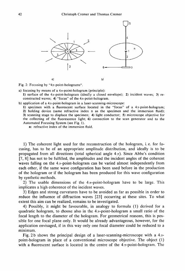
42 Chr is toph Cremer and Thomas Cremer
0 5
c 2 6- 3
b)
F i g . 2: Focusing by "4,T-point-holograms".
a) focusing by means of a 47r-point-hologram (principle): 1) surface of the 4;r-point-hologram (ideally a closed envelope); 2) incident waves; 3) reconstructed waves; 4) "focus" of the 4rr-point-hologram.
b) application of a 4rr-point-hologram in a laser-scanning-microscope: 1) specimen wi th a fluorescent surface located in the "focus" of a 4;r-point-hologram; 2) ho ld ing device (same refractive index n as the specimen and the immersion fluid); 3) scanning stage to displace the specimen; 4) l ight conductor; 5) microscope objective for the collecting of the fluorescence light; 6) connection to the scan generator and to the Automated Focus ing System (see F i g . 1).
n: refractive index of the immersion fluid.
1) The coherent light used for the reconstruction of the hologram, i. e. for focusing, has to be of an appropriate amplitude distribution, and ideally is to be propagated from all directions (total spherical angle ATI). Since Abbe's condition [7, 8] has not to be fulfilled, the amplitudes and the incident angles of the coherent waves falling on the 4jr-point-hologram can be varied almost independently from each other, if the same wave configuration has been used before in the production of the hologram or if the hologram has been produced for this wave configuration by synthetic methods.
2) The usable dimensions of the 47r-point-hologram have to be large. This implicates a high coherence of the incident waves.
3) Edges and strong curvatures have to be avoided as far as possible in order to reduce the influence of diffraction waves [23] occurring at these sites. To what extent this aim can be realized, remains to be investigated.
4) Possibly, it might be favourable, in analogy to formula (1) derived for a quadratic hologram, to choose also in the 4rr-point-hologram a small ratio of the focal length to the diameter of the hologram. For geometrical reasons, this is possible for one focal plane only. It would be already advantageous, however, for the application envisaged, if in this way only one focal diameter could be reduced to a minimum.
Fig. 2 b shows the principal design of a laser-scanning-microscope with a 4rr-point-hologram in place of a conventional microscope objective. The object (1) with a fluorescent surface is located in the centre of the 4,i-point-hologram. The

Considerat ions on a laser-scanning-microscope 43
diameter of the hologram is assumed to be large compared with the dimensions of the object. The object is placed on a holding device (2), the refractive index n of which is equal to that of the object itself. The interior of the hologram is filled with an immersion fluid of refractive index n . A small hole in the 4:rr-point-hologram serves to connect the holding device (2) to a scanning stage (3). The fluorescent light emitted by the object is collected by a light conductor (4) which is connected to a microscope objective (5). The light signal is processed in the same way as in the laser-scanning-microscope designed in Fig. 1. It is of importance that the geometry of the light conductor is chosen in such a way that the part of the specimen surface which contributes to the luminous flux collected by the light conductor is as small as possible. It is assumed that by means of the holographic focusing the excitation light is focused on an area of the surface with a diameter which is con-siderably smaller than the wavelength used, and that the absorbance by the holding device and the object is small. Since the excitation light is incident from all direc-tions, also the object surface outside the focus is excited to fluoresce. This back-ground fluorescence is estimated to be small compared with the signal, if the thick-ness of the surface layer contributing to the fluorescence is considerably smaller than the "focus diameter".
The use of plane point-holograms for focusing the exciting beam in the laser-scanning-microscope seems to be realizable without difficulties and suggests to be advantageous at least with respect to the much larger working distance available compared with conventional microscope objectives of high numerical aperture. Whether it might be possible to produce point-holograms in which a larger spheri-cal angle than approx. 2n is used for focusing, and whether such holograms might be really used in a laser-scanning-microscope, remains to be investigated. Perhaps the use of non-plane point-holograms might result in a better focusing even if the spherical angle is considerably smaller than 4 TT.
The above-said speculations on focusing by "4^-point-holograms" are only intended to allude to a method which perhaps might be used to enhance the resolving power of a laser-scanning-microscope by means of holographic focusing. To our knowledge, a detailed investigation of the principal theoretical and practical limitations of holographic focusing with non-plane point-holograms does not exist. We feel this to be an interesting subject, independently of the field of application envisaged here.
A c k n o w l e d g e m e n t
W e wish to thank D r . J . S. P l o e m , Univers i ty of Le iden (The Netherlands), for valuable discussion.
References
[1] Barakat, R.: T h e i n t e n s i t y d i s t r i b u t i o n a n d t o t a l i l l u m i n a t i o n of a b e r r a t i o n - f r e e d i f f r a c t i o n i m a g e s . In: E . W o l f (Edit.): P r o g r e s s i n O p t i c s , V o l . I, pp. 67—108. N o r t h - H o l l a n d P u b l . C o . , Amsterdam 1965.
[2] Bennett, S. D . : T h e s c a n n i n g a c o u s t i c m i c r o s c o p e . In: G . A . H a y (Edit .): M e d i c a l I m a g e s : F o r m a t i o n , P e r c e p t i o n a n d M e a s u r e m e n t , pp. 122—135. (The Institute of Physics.) John W i l e y & Sons, Chichester-New Y o r k 1976.

44 Chr is toph Cremer and Thomas Cremer
[3] Berei ter-Hahn, J . : L a s e r a l s M i k r o m a n i p u l a t o r i n B i o l o g i e u n d M e d i z i n : 1 . G r u n d l a g e n der A n w e n d u n g v o n L a s e r l i c h t zur M i k r o b e s t r a h l u n g b i o l o g i s c h e r O b j e k t e . Mic rosc . A c t a 71, 225—241 (1972).
[4] Berei ter-Hahn, J . : L a s e r a l s M i k r o m a n i p u l a t o r i n B i o l o g i e u n d M e d i z i n : 2. M e t h o d i k u n d A n w e n d u n g der L a s e r - M i k r o b e S t r a h l u n g b i o l o g i s c h e r O b j e k t e . M i c r o s c . A c t a 72, 1—33 (1972).
[5] Berns, M . W . : B i o l o g i c a l M i c r o i r r a d i a t i o n . C l a s s i c a l a n d L a s e r Sources. Prent ice-Hal l , Inc., Englewood Cliffs , N . J . 1974.
[6] Bjorken, J . D . , und S. D . D r e l l : R e l a t i v i s t i s c h e Q u a n i e n f e l d t h e o r i e . Bibliographisches Institut, M a n n h e i m 1967.
[7] Born , M . : O p t i k . E i n L e h r b u c h der e l e k t r o m a g n e t i s c h e n L i c h t t h e o r i e , 2. A u f l . Springer-Ver lag , Ber l in-Heidelberg-New Y o r k 1965.
[8] Born , M . , and E . W o l f : P r i n c i p l e s of O p t i c s . E l e c t r o m a g n e t i c T h e o r y o f P r o p a g a t i o n , I n t e r f e r e n c e a n d D i f f r a c t i o n of L i g h t . 4*h E d i t i o n . Pergamon Press, O x f o r d - L o n d o n 1970.
[9] Car l son , F . E . , and C . N . C l a r k : L i g h t sources f o r o p t i c a l devices. In: R . Kings lake (Edit.): A p p l i e d O p t i c s a n d O p t i c a l E n g i n e e r i n g , V o l . I, pp. 43—109. Academic Press, N e w Y o r k and L o n d o n 1965.
[10] Claussen, H . C : M i k r o s k o p e . In: S. F l ü g g e (Hrsg.): H a n d b u c h der P h y s i k , B d . X X I X ( O p t i s c h e I n s t r u m e n t e ) , pp. 343—425. Spr inger-Verlag, Ber l in-Heide lberg-New Y o r k 1967.
[11] Cremer, C , und T . Cremer: 4 j i - P u n k t h o l o g r a m m e : P h y s i k a l i s c h e G r u n d l a g e n u n d mögl i c h e A n w e n d u n g e n . In: Patentschrift P 21 16 521.9 („Verfahren zur l i n s e n f r e i e n E r z e u g u n g v o n K u g e l w e l l e n " , A n m . C . Cremer und T . Cremer) . Deutsches Patentamt, Dienststelle Ber l in , Patentschriftenvertriebsstelle 1971.
[12] Cremer , C , C . Z o r n , and T . Cremer: A n u l t r a v i o l e t l a s e r m i c r o b e a m f o r 2 5 7 n m . Mic rosc . A c t a 75, 331—337 (1974).
[13] Cremer, C , T . Cremer , C . Z o r n , and L . Schoeller: E f f e c t s of l a s e r u v - m i c r o i r r a d i a t i o n ( 1 = 2573 Ä) o n p r o l i f e r a t i o n of Chinese hamster c e l l s . Radiat . Res. 66, 106—121 (1976).
[14] Dan ie l , J . C . jr., and K . Takahashi : Selective l a s e r d e s t r u c t i o n of r a b b i t b l a s t o m e r e s a n d c o n t i n u e d c l e a v a g e of s u r v i v o r s i n v i t r o . E x p . C e l l Res. 39, 475—482 (1965).
[15] Egner, O., und J . Berei ter-Hahn: L a s e r - S t r a h l e n s t i c h v e r s u c h e a n F i s c h - M e l a n o p h o r e n . Z . wiss. M i k r o s k . 70, 17—22 (1970).
[16] H i l l enkamp , F . , R . Kaufmann und E . R e m y : D e r L a s e r a l s I n s t r u m e n t der Z e l l f o r s c h u n g i m M i k r o - u n d S u b m i k r o b e r e i c h . L A S E R 3 (4), 40—42 (1971).
[17] K i e m l e , H . , und D . Röss : Einführung i n d i e T e c h n i k der H o l o g r a p h i e . Akademische V e r -lagsges., Frankfur t a. M a i n 1969.
[18] Leis , R. : V o r l e s u n g e n über p a r t i e l l e D i f f e r e n t i a l g l e i c h u n g e n z w e i t e r O r d n u n g . B ib l io graphisches Institut, M a n n h e i m 1967.
[19] Lemons , R. A . , and C . F . Quate: A c o u s t i c m i c r o s c o p y : b i o m e d i c a l a p p l i c a t i o n s . Science 188, 905—911 (1975).
[20] P loem, J . S.: Q u a n t i t a t i v e f l u o r e s c e n c e m i c r o s c o p y . In: G . A . Meek , and H . Y . E ider (Edits.): A n a l y t i c a l a n d Q u a n t i t a t i v e M e t h o d s i n M i c r o s c o p y , pp. 55—89. Cambr idge U n i versity Press, Cambridge 1977.
[21] Rempel , R . C : O p t i c a l p r o p e r t i e s of l a s e r s as c o m p a r e d t o c o n v e n t i o n a l r a d i a t o r s . Spectra-Physics Laser Technical Bul le t in 1, 1—9 (1963).
[22] Rounds, D . E . : L a s e r a p p l i c a t i o n s t o b i o l o g y a n d m e d i a n e . In : L a s e r H a n d b o o k , V o l . II, pp. 1863—1890. N o r t h H o l l a n d P u b l . C o . , Amste rdam 1972.
[23] Rub inowicz , A . : D i e B e u g u n g s w e l l e i n der K i r c h h o f f s c h e n T h e o r i e der B e u g u n g . Panst-wowe Wydawnic two Naukowe , Warszawa 1957.
[24] Tradowski , K . : Laser. Voge l -Ver l ag , W ü r z b u r g 1968. [25] Z o r n , C , T . Cremer, C . Cremer, and J . Z i m m e r : L a s e r uv m i c r o i r r a d i a t i o n of i n t e r p h a s e
n u c l e i a n d p o s t - t r e a t m e n t w i t h c a f f e i n e . H u m . Genet. 35, 83—89 (1976).