journal of pipeline safety volume i number i autumn …pstrust.org/docs/ops_doc1.pdf · of pipeline...
TRANSCRIPT

of Pipeline Safety__ Journal Safe Separation Distances From Natural Gas Transmission Pipelines A Practical Approach to Operator Qualification A~licatiofls and Beflefits of using Cathera Technology tointernally Inspect Polyethylene Main and Service Proposed Methodology for Detecting Localized External CorrOsion.Activity on Underground* PipÈlineSystems Using Ac-ImPedance, and Pattern RecognitiOn Algorithm OPS Regulatory Agenda Watch. WPL Publishers since 1987:. - , - `Volumel N¸rnberlAUti.trnn 1999 -`A

Journal of Pipeline Safety Volume I Number I Autumn 1999WPLPublishers since 1987

VoJume 1 Number 1 Autumn 1999 Journal of Pipeline SafetyPage1 From the Editor Alex Marks3 Safe Separation Distances From Natural Gas Transmission Pipelines James S. Hakiar and Robert Dresnack21 A Practical Approach to Operator Qualification John Erickson35 Applications and Benefits of Using Camera Technology to Internally Inspect Polyethylene Main and Service Piping Anita Romero41 Proposed Methodology for Detecting Localized External Corrosion Activity on Underground Pipeline Systems Using AC-Impedance and Pattern Recognition Algorithm M Urquidi-Macdonald and H. Castaneda57 OPS Regulatory Agenda Watch JPS Staff

Editor-in-Chief: Alex Marks Managing Editor: Susan WalkerJournal of Pipeline Safety is published twice per year byWashington Pipeline Letter, P.O. Box 23675, L'EnfantPlaza, Washington, DC 20026-3675. Copyright © 1999,Washington Pipeline Letter. All rights reserved.No part of this publication may be reproduced in any formor by any means, except as permitted under Section 107 or108 of the 1976 United States Copyright Act, withouteither the prior written permission of the publisher.The copyright notice indicates the copyright holder'sconsent that copies may be made for personal or internaluse, or for the personal or internal use of specific clients,on the condition that the copier pay for copying beyondthat permitted by law.This consent does not extend to other kinds of copying,such as copying for general distribution, for advertising orpromotional purposes, for creating new collective works,or for resale. Such permission requests and otherpermission inquiries should be addressed to the Journal ofPipeline Safety, Permissions, P.O. Box 23675, L'EnfantPlaza, Washington, DC 20026-3675.Subscription price 1999/2000One year, $299 US in U.S., Canada, and Mexico; $323outside North America. All payments must be made inU.S. dollars. Claims for undelivered copies will beaccepted only after the following issue has been received.Please enclose a copy of the mailing labels. Missing copieswill be supplied when losses have been sustained in transitand where reserve stock permits. Please allow four weeksfor processing a change of address. For subscriptioninquiries, please call 1-888-720-8136 or E-mail:wplbsa~agt.net.All correspondence should be addressed to: Journal ofPipeline Safety, P.O. Box 23675, L'Enfant Plaza,Washington, DC 20026-3 675, Attn: Susan Walker,Managing Editor.This publication is designed to provide accurate andauthoritative information in regard to the subjectmatter covered. It is sold with the understanding thatthe publisher is not engaged in rendering legal,accounting, or other professional service. EDITORIAL GUIDELINES FOR AUTHORS Journal of Pipeline Safety is written for pipeline safety managers, engineers and attorneys. Authors must keep this readershipin mind. Articles should be informative, analytical, and practical, but not highly technical. We seek material that will offer ourreadership new understanding of and effective, practical approaches to pipeline safety compliance. Manuscripts are considered for publication with the understanding that they represent original material, and are offeredexclusively and without fee to Journal of Pipeline Safety. Articles must not have been published previously and may not simultaneously be submitted elsewhere. An original and one copy of the manuscript must be submitted. Any accompanying artwork or exhibits must be submitted asblack and white originals suitable for reproduction. Articles should range from 3,700 to 7,500 words 15 to 30 pages, on one side only of 8 Yz' x 11" heavy-duty white bondpaper. Margins should be set to allow for 55 characters per line. A one-and-one-half-inch margin should be left at the top and bottomof each manuscript page. Try to use asfewfooznotes as possible. If they are indispensable to the subject, they should appear double-spaced on aseparate page at the end of the article. Send photocopies of original sources of lengthy quotations. This enables us to confirm the accuracy of the quotation. Please seek clarity, brevity, and pertinence. Titles of articles should be short and clear. All accepted manuscripts are subjectto editing. A brief- 50 words or less - biographical sketch of the author should accompany the article. The sketch should name theauthor's position, company or other professional organization, and field of expertise. A lOO-to-125 word summary of the article should also be provided. All unsolicited manuscripts must be accompanied by a self-addressed, stamped envelope. Otherwise, they cannot be returnedto the author. Address articles to: Journal of Pipeline Safety, Susan Walker, Managing Editor, do WPL, P.O. Box 23675, L'Enfant Plaza,Washington, DC 20026-3675.

From the Editor Alex MarksFor over 14 years now, writing for the Washington Pipeline Letter, whereeditorial and subjective comment are almostentirely absent, it is an abrupt change for meto write an editorial. Needless to say, it is aprivilege for me to serve you with thiseditorial to the first issue of the Journal ofPipeline Safety.So, it is with a sense of pride that I wouldlike to present to you the authors writing forthis premiere issue of the JPS. The solepurpose of this journal is to providebeneficial information to you the reader, thatwill help you to comply with the pipelinesafety regulations and enhance pipelinesafety for everyone's benefit. Moreover, theinformation is presented here with thethought that it will help you to gain contextand perspective on key regulatory issuesbeing developed by the Office of PipelineSafety. That is to say, the JPS is intended tobe an instrument for open, scientific, andscholarly exchanges that will result in realsolutions to real pipeline safety problems.Moving along to the first article, Dr. J.S.Hakiar and Dr. Robert Dresnack haveinvestigated gas transmission pipelineincidents that result in rupture and gasignition. They propose a method forevaluating distances that pipelines can besafely set back from the community, calledsafe separation distances. In the last OPSSafety Advisory Committee meeting inNovember 1999, in Washington, D.C.,difficulties encountered by firefighters at theEdison, N.J. pipeline incident of March 23,1994 were emphatically expressed. Thisarticle is timely in examining some of thefactors involved in dealing with this type ofincident.Mr. John Erickson examines the history ofthe Operator Qualification rule, reviewsaccident data to estimate its potentialbenefits, and describes steps that operatorsmust take to comply with the regulation. Theauthor, while at the American GasAssociation, was one of the architects of therulemaking.Ms. Anita Romero describes how SouthwestGas met two challenges dealing with: 1cold fusion joint failures; and 2determination of unknown pipe materials,and solved them cost- effectively. Thisarticle is pertinent in as much as OPS iscurrently involved in determining the safetyof plastic pipeline systems and how best toenhance their reliability.Dr. Mima Urquidi-Macdonald and Dr. H.Castaneda present a methodology fordetecting and locating defects ordiscontinuities on the outside coating of in-service pipelines with or without cathodicprotection. This article is relevant since OPSand the industry are continually addressingpipeline corrosion control issues. They areJOURNAL OF PIPELINE SAFETY / Autumn 1999/ 1

searching for an opportunity to test thispredictive system in a large "real life"operation.Finally, a standard feature in the Journal ofPipeline Safety, "Regulatory AgendaWatch" has been prepared by the JPS staff.An overview of the latest Pipeline Safetyregulatory agenda 64 FR 64851; 11/22/99is presented here to enable interested partiesto prudently monitor, and plan their pipelinesafety regulatory compliance efforts. It alsoprovides JPS authors with a common basefor addressing pending issues and how bestto comply effectively and efficiently.We aim to publish the JPS biannually atfirst, with the intention of producing aquarterly journal if the volume and caliber ofresearch papers submitted will support it.The JPS is priced affordably to serve a broadspectrum of members of the pipelineindustry community.Participation is encouraged from industry,academia and government. All articles willbe peer-reviewed by qualified scholars, andthe decision to publish will be based ontechnical merit and contribution to the goalsof the JPS.You are invited and encouraged to submityour comments, letters to the editor, oropinions which we welcome. Thank you toeach of the authors for their time and effortin preparing these important articles and tothe JPS support staff without whom thispublication would not be possible.2/ Autumn 1999 / JOURNAL OF PIPELINE SAFETY

Safe Separation Distances From Natural Gas TransmissionPipelines Abstract James S. Haldar, Ph.D., P.E. and Robert Dresnack, Ph.D., P.E. New Jersey Institute of Technology Newark, N.J. Accidental rupture of natural gas transmission pipelines with subsequent ignition of the escaping gas can result in the loss of l~fe and property. A method for evaluating distances at which the pipelines can be safrly set back from the community, called safr separation distances, is proposed herein, in which the point source method for determining heat flux is coupled with relationships for predicting both the mass release rate from the rupture and the flame height of the ignited gas. The method is utilized to develop charts for predicting saft separation distances based on pipeline operating pressure and nominal pipeline diameter.IntroductionIncreased development of formerly sparsely populated areas has resulted ininstances of encroachment of natural gastransmission pipeline rights-of-wayROWs. Accidental ruptures of thesepipelines with subsequent ignition of theescaping gas can result in the loss of life andproperty near these lines. A description ofthe effects of such accidents can be found inthe pipeline accident reports prepared by theNational Transportation Safety BoardNTSB, the independent Federal agencythat investigates pipeline accidents occurringin the United States.One example of the destructive effects ofpipeline ruptures was the explosion, inEdison, New Jersey, of a 36-inch pipelineoperating at a pressure of 970 psig. Thisaccident occurred on March 23, 1994 andseverely affected a nearby apartmentcomplex. The apartment complex sustained$12.4 million in damages, which includedthe loss of eight apartment buildings, severedamage to six buildings and minor damageto several other building NTSB, 1995.This accident served as the basis for theevaluation, described in this paper, of theproximity at which pipelines can be safelysited near a community. These distances arecalled "safe separation distances."JOURNAL OF PIPELINE SAFETY / Autumn 1999/ 3

In general, both the United States andforeign countries address the establishmentof separation distances either directly, ormdirectly through the designation of variouslocation or population classes. In thoseinstances where a defined allowable ROWhas been established, the width of the ROWfrom the pipe centerline is relatively smallless than 100 feet and is generally intendedto protect the pipe rather than the public.Separation distances have also beendeveloped by some countries based on theconcept of risk assessment. This paperdescribes the development of a methodologyto estimate actual separation distancesrequired, based upon the effects of a ruptureof a natural gas transmission pipeline of aspecified diameter and operating pressure.The methodology is developed, in part, withdata collected from prior investigations ofactual natural gas transmission pipelineaccidents.Literature ReviewThe purpose of the literature review was togain an understanding of prior researchconcerning both natural gas pipelineaccidents and the determination of safeseparation distances from natural gastransmission pipelines. Activities associatedwith the literature review included review ofNTSB files and Commodity PipelineOccurrence Reports prepared by theCanadian Transportation Safety BoardTSB. Other activities consisted ofdiscussions of the issue of safe separationdistances with the European Gas PipelineIncident Data Group located in theNetherlands, the NTSB, the Canadian TSB,the Canadian National Energy Board, theUnited States Environmental ProtectionAgency, the American Gas Association, theResearch and Special ProgramsAdministration, the Gas Research Institute,and the Township of Edison. Finally,various texts and technical journals of the oiland gas pipeline industry were reviewedpertaining to pipelines, hazard assessment,heat transfer and fluid flow.In general, the literature review revealed thatthere has been limited studies to dateconcerning the determination of safetyseparation distances. The prior researchreviewed is predominantly concerned withpredicting the loss of product during anactual pipeline rupture i.e., blowdown,rather than directed to concerns associatedwith establishment of adequate saleseparation distances for the public.The modelling of product loss during apipeline rupture, which is an importantfactor related to the establishment of a safeseparation distance therefrom, is, asindicated in a number of research papersreviewed, difficult to simulate. This is dueto disparity amongst researchers as to theconditions under which the blowdown ismodelled e.g., adiabatic or isothermal;whether the fluid is viscous or nonviscous,etc..The literature review also revealed that theavailable database of information associatedwith actual natural gas pipeline accidentoccurrences in the United States and Canadais limited. For example, the pipelineaccident reports PARs prepared by theNTSB do not consistently report parameterssuch as the total volume of gas lost in anaccident, or the location of the closest valves4 / Autumn 1999 / JOURNAL OF PIPELINE SAFETY

upstream and downstream of the pipelinerupture. Furthermore, supportinginformation for the more dated PARs in thePAR dockets in Washington, DC isperiodically destroyed. The CommodityPipeline Occurrence Reports prepared by theCanadian TSB are similar to the PARs inthat there are also inconsistencies in theextent of information contained in thesereports.Because of the aforementioned reasons, itwas concluded that an approach to advancethe state-of-the-art in the discipline ofpipeline risk analysis is to develop a reliableestimation technique to conservativelypredict safe separation distances to bearticulated between the public and theruptured natural gas pipeline.MethodologyThe simplified approach for estimating safeseparation distances was developed basedupon assumptions that the damage from apipeline rupture is primarily due to thethermal radiation produced by the ignitedgas behaving like a vertical jet flame. Thethermal radiation will produce an impactarea, the extent of which can be detenninedthrough the estimation of a "bum radius".The major variables associated with the burnradius resulting from a pipeline rupture arethe size of the pipeline and its operatingpressure which directly affects the massflow rate in the pipeline. Theappropriateness of this approach inproviding results of an accuracy suitable forregulatory agencies to utilize for establishingzoning guidelines was confirmed bycomparing results from the aforementionedmodel with actual bum radii found in alimited number of accident investigationsconducted by the NTSB in which sufficientdata was obtained to verify the subjectmodel herein.As indicated above, an assumption is madethat the damage from a pipeline rupture isprimarily due to the thermal radiationproduced by the ignited gas. Therefore, asafe separation distance is defined as thedistance beyond which a pre-establishedlevel of thermal radiation damage will notlikely occur. Other damage such asprojectile damage from pipeline fragmentsor damage due to over pressures fromexplosions is not considered. Thisassumption is consistent with the resultsfrom investigations of actual pipelineruptures, in which damage was found to becaused primarily from the fire. Therefore,the safe separation distance from a pipelinecan be defined in terms of the distanceneeded to protect against a specified heatflux. This specified heat flux will producean area of thermal radiation damage in thevicinity of the pipeline which can beestimated by calculating the bum radius.Use of the Point Source MethodThe point source method forms the basis forthe estimation of safe separation distances.The following equation is presented fromthe work of Oenbring and Sifferman 1980:K = FQ/4irD21where K = radiation heat flux from a flameBtu/hr ft2; F = fraction of total heatradiated; Q = total heat content of the flaredJOURNAL OF PIPELINE SAFETY I Autumn 1999 / S
gas Btulhr; and D = distance from pointsource to receptor ft.Those authors provide the source forEquation 1 as being the AmericanPetroleum Institute API document APIRP-521. In a later version of this documentAPI, 1990, API provides the revisedequation: D = tFQ/4itK~ 2where r = the fraction of thermal radiationtransmitted through the atmosphere.Application of the point source method isshown in Figure 1, where ignition ofescaping gas from a pipeline rupture resultsin a flame of height "H". The point sourceis placed in the center of the flame at H/2,and the burn radius BR is found from thePythagorean. Theorem:BR = {D2 - HI22}~3By inserting Equation 2 into Equation 3, thefollowing relationship is obtained: BR = {tFQ/4itK - H/22} Y~ 4This is the basic form of the burn radiusequation. The bum radius is function of thetransmissivity of the thermal radiationthrough the atmosphere, the fraction of totalheat radiated, the heat content of theescaping gas, the specified heat flux orlevel of damage, and the flame height.Based on information provided by variousresearchers for methane NFPA, 1988, thevalue ofF can be reasonably estimated to be0.2. Calculation of the transmissivity ofthermal radiation through the atmospherewas performed using the method ofBrzustowsi and Sommer 1973, asdiscussed by API API. 1990. By assuminga relative humidity of 50% and a distance tothe flame of 500 feet both of which arereasonable values for pipelineaccidentscenarios, the atmospheric transmissivity isdetermined to be 0.746. Inserting the valuesoft and F into Equation 4, the equation forthe burn radius becomes:BR= {0.011873Q1K - FJ22}º5The total heat content of the escaping gasQ in Btu!hr can be found by multiplyingthe heat content of natural gas 1,000Btulscf by the volumetric flow rate of theescaping gas scUhr:Q = 1,000V'6where V' = volumetric flow rate scf7hr. IfEquation 6 is inserted into Equation 5, theexpression for the bum radius becomes: BR = {11.873V'/K - H/S2}~ 7Determination of Gas Flow RateThe volumetric flowrate of the escaping gas,V', can be found using a modified form ofan equation, found in the Pipe Line Rules ofThumb Handbook, McAllister, 1993,which is used when calculating the volumeof gas lost through a puncture or blowdown.This equation is expressed as:Q=D2P18where: Q = volume of gas in Mcflhr at a6/Autumn 1999/ JOURNAL OF PIPELINE SAFETY

pressure of 14.9 psi, 60°F with a specificgravity of 0.60; D = diameter of the nippleor orifice in inches; and P1 = absolutepressure in psi at some nearby pointupstream from the opening.Equation 8 is modified by examining therates of gas lost through actual pipelineruptures see Table 1 and comparing theserates with values obtained using theequation. Based on this evaluation,Equation 8 was modified to be:V1 = 1,0000.34IYP9where V1 = gas flow rate, scflhr; D =pipeline diameter, inches; and P = incidentoperating pressure, psia. It should be notedthat multiplication by 1,000 in Equation 9converts McI/hr to scfYhr. Equation 9reflects the fact that insertion of themaximum initial flow rate into the pointsource equation will not accurately reflectthermal radiation conditions, since the heatflux at a given receptor location willdecrease with the decreasing gas flow.Therefore, V' can be considered to be arepresentative gas flow rate.Determination of Flame HeightIn a manner similar to the method fordetermining the expression for gas flow rate,the information obtained from actualpipeline accidents can be used to estimateflame height. Hawthrome, Weddell andHottell 1949 developed an equation that,for a given gas, expressed the flame lengthas being directly proportional to the jet ornozzle diameter. This observation can beapplied to the NTSB pipeline accident dataof Table 2, where estimation of flameheights are provided. If the assumption ismade that the jet diameter is equal to thepipeline diameter for a full bore rupture, thefollowing relationship is obtained:H= 147D/12 = 12.25Dwhere D = pipeline diameter in.10By inserting Equation 9 and Equation 10into Equation 7, the final burn radiusequation is found: BR=D{4,036.82P/K- 37.52}~ 11where BR = bum radius ft; D = pipelinediameter in; P incident operatingpressure psia; and K = heat flux Btu/hrft2.Equation 11 provides a means by which theburn radius and hence the safe separationdistance can be found knowing only thepipeline diameter, incident operatingpressure and the level of damage i.e., heatflux to be considered. Since pipelineoperating pressures are typically specified asgauge pressures, Equation 11 can bemodified for application to gauge pressuresby substituting the quantity P' + 14.7 forP, where P' is the incident operatingpressure in psig.Heat Flux ValuesSeveral examples of heat flux valuescorresponding to specific consequences areprovided in Table 3. These values wereobtained from a review of the literature.JOURNAL OF PIPELINE SAFETY / Autumn 1999 / 7

From these heat flux values, it can be seenthat the level of thermal radiation damagemay not only depend on the intensity of theheat flux, but also on the length of time thatthe receptor is receiving that heat flux. Forexample, at a heat flux intensity of 9,985BtuThr ft2, spontaneous ignition of woodenbuilding occurs after afew minutes.Similarly, the maximum tolerable heat fluxfor short-term exposure for people is 2,000Btu/hr ft2. Therefore, a safe separationdistance is considered to afford protectionfrom a certain level of heat flux for aspecific time period. If that time period isexceeded, damage may occur.In order to estimate a safe separationdistance, a level of protection is chosen,such as protecting wooden buildings fromspontaneous ignition for a few minutes. Thecorresponding heat flux is found andinserted intoEquation 11 as the appropriateK-value.Construction of Charts to Predict SafeSeparation DistancesThe following procedure is used to constructcharts for the estimation of safe separationdistances. The first step involves decidingthe degree of thermal radiation damage toconsider. For example, the damage might bespontaneous ignition of wooden buildingsafter a few minutes exposure to the ignitedgas. Protection for a few minutes may allowenough time for emergency responders toarrive at the scene and initiate protectivemeasures such as watering down thebuilding. Based on the informationprovided in Table 3, the heat fluxcorresponding to the specified level ofdamage is 9,985 Btulhr ft2. This value isinserted into Equation 11 for K:BR = D {4,036.82P/9,985 - 37.52} ~2 12Equation 12 is an expression of the bumradius as a function of only diameter andincident operating pressure. For variouspipeline diameters, charts are thenconstructed of the bum radius on the y-axisand the incident operating pressure on thex-axis. In the example, a pipeline diameterof 36" can be used with incident operatingpressures in the range of 575 psia to 1,200psia to construct a chart similar to the oneshown in Figure 2. Once the chart iscompleted, it can be used either to determinea safe separation distance given a specifiedincident operating pressure, or to determinethe incident operating pressure required tomaintain a specified safe separationdistance.Charts for estimating safe separationdistances or bum radii were developed forheat flux values of 3,962 Btu/hr ft2 pilotedignition of wood; 6,340 Btulhr ft2blistering of bare skin in 4 seconds and 1percent lethality in 20 seconds; 9,510Btulhr ft2 causes third degree bums in 30seconds; and 9,985 Btu/hr ft2 spontaneousignition of wooden structures after a fewminutes. The charts have been developedfor pipeline diameters of 14", 16", 18", 20",24", 30" and 36", with incident operatingpressures in the range of 575 psia to 1,200psia. It should be noted that the charts donot consider that portion of the heat flux dueto solar radiation. An accurate value of thesolar heat flux would be dependent onfactors such as the weather conditions, thetime of day and the time of year. Since the8/ Autumn I 999 / JOURNAL OF PIPELINE SAFETY
solar heat flux amounts to only a fewhundred Btu/hr ft2 while the non-solar heatflux is several thousand Btulhr ft2, omissionof this factor will not significantly affect theresults.Comparison of Method to PipelineAccident Data and to Previous ResearchEquation 11 was evaluated by firstcomparing the calculated values for burnradii to data from documented pipelineaccidents that occurred in the United States.The previously-mentioned accident thatoccurred in Edison, New Jersey is presentedhere as an example of the analysis that wasperformed.The PAR NTSB, 1995 for the Edison,New Jersey accident describes the rupture ofa 36 inch natural gas transmission pipelineowned and operated by the Texas EasternTransmission Corporation. The ruptureoccurred at approximately 11:55 p.m. onMarch 23, 1994, on the property of QualityMaterials, Inc. in Edison, New Jersey.Ignition of the escaping gas occurred within2 minutes after the rupture, producingflames 400 to 500 feet high. While nodeaths were directly attributed to theaccident, the rupture produced extensivedamage including the destruction of severalbuildings of a nearby apartment complex.The total cost of the damage exceeded 25million dollars. The NTSB determined thatthe probable caused of the rupture wasmechanical damage to the exterior pipelinesurface. The damage reduced the pipelinewall thickness and probably resulted in acrack that grew to a critical size.As indicated previously, the ruptureoccurred at approximately 11:55 p.m., withignition of the gas less than two minuteslater. Based on the PAR, the EdisonTownship Fire Department arrived at theaccident scene at approximately 12:02 a.m.According to information provided by theTownship of Edison personalcommunication, 1996 there were severalbuildings that were involved in fire uponarrival of the Fire Department, and therewere other buildings that would have burnedif those structures were not wetted down.If buildings were set back from the pipelineat a distance beyond the location of thebuildings which were involved in fire after afew minutes exposure to thermal radiation,then this distance would have providedprotection for a few minutes fromspontaneous ignition. Using informationfrom the files of the NTSB, the distancefrom the rupture and the approximatemidpoint of the footprint for the buildingfarthest from the rupture that was becominginvolved in fire when the Fire Departmentarrived was determined to be approximately772 feet.In order to use Equation 11, an appropriateheat flux must first be selected. Since theconcern is protecting structures fromspontaneous ignition for several minutes, aheat flux of 9,985 Btu/hr ft2 from Table 3 isselected. Inserting this value for heat fluxinto Equation 11, as well as the applying thepipeline diameter of 36 inches and theincident operating pressure of 984.7 psia, theburn radius becomes: BR = 36{[4,036.82984.7I9,985] - 37.52}~ =684 feetJOURNAL OF PIPELINE SAFETY / Autumn 1999 / 9

The estimated burn radius differs from theactual burn radius by less than 12 percent. Itcan therefore be seen that the predicted burnradius does in fact approximate the distanceto those buildings which were involved infire a few minutes after the rupture.A burn radius can likewise be estimated fordetermining the distance beyond whichbuildings will not ignite at all. For theEdison accident, this distance would extendbeyond the location of those buildings whichwere wetted down. In order to predict thedistance with Equation 11, a heat flux of3,962 Btu/hr ft2 is selected. This is the heatflux at which piloted ignition of woodoccurs, so that wood is not expected toignite below this heat flux. From equation11, the burn radius becomes: BR = 36 { [4,036.82984.7/3,962] - 37.52} ~ =1,119 feetThe actual distance from the rupture point tothe midpoint of the building farthest fromthe rupture that was wetted down waslikewise found using the information fromthe NTSB files for this accident. Thisdistance was determined to be 1,101 feet.The predicted burn radius is therefore verysimilar to the actual distance, with adifference of less that 2 percent.The following example illustrates theanalysis of a safe separation distance for apipeline accident for which less informationis available NTSB, 1986. The accidentoccurred in Jacksonville, Louisiana, onNovember 25, 1984. The pipeline had adiameter of 30 inches and was operating at1,016 psig 1,030.7 psia. A non-symmetrical damage area was produced,with the rupture incinerating an area 900 feetnorth, 500 feet south and 180 feet to the eastand west of the rupture. If the bum radius isconsidered to be the maximum lineardistance from the rupture to the edge of theincinerated area, the radius is then 900 feet.Again, using Equation 11 and a heat flux of3,962 Btu/hr ft2 i.e., a conservative valuefor heat flux which will cause an area to beburned, the estimated burn radius becomes: BR = 30{[4,036.821030.7/3,962} - 37.52}~ =955 feetThe estimated burn radius differs from theactual burn radius by only 6 percent.Comparison to Separation DistancesDeveloped through Hazard AnalysisSeparation distances produced by Equation11 were compared to separation distancesdeveloped through the principles of hazardanalysis. For example, Hill and Catmurperformed a study for the British Health andSafety Executive 1995 to evaluate howrisks from various hazardous pipelinescompared. As part of the study, distancesfrom a vertical flame jet to a heat flux levelof 10 kW/m2 3,170 Btu/hr ft2 are providedfor the pipelines under consideration. Theflame was simulated as an inclined linesource with a receptor 1.5 meters 4.92 feethigh at ground level. Furthermore, theauthors indicate that the model which wasused provides the maximum view factorbetween the source and receptor, with thethermal radiation being a function of theflame's emissivity, the transmissivity of theair, the view factor and the radiant energy ofthe burning compound.10 / Autumn 1999 / JOURNAL OF PIPELINE SAFETY

A comparison was made between thosedistances and the distances estimated usingEquation 11. This comparison is presentedin Table 4, for all of the natural gas pipelines.involved in the study. It can be seen thateven outside the range of diameters andpressures for which Equation 11 wasdeveloped that this relationship stillproduces results which approximate those ofthe British. The higher percent differencesreflected in the last three entries of Table 4are probably due to the use of low operatingpressures, either singly or in combinationwith small diameters, which are outside therange for which Equation 11 was developed.A comparison was likewise made betweenseparation distances determined through useof Equation 11 and the separation distancesimposed in regulations developed by theDutch. The following discussion is based oninformation from personal communicationswith N.V. Nederlandse Gasunie November30, 1995, June 21, 1996, September 30,1996. The first type of separation distancewhich the Dutch developed is called aproximity, or building distance. This is thedistance between a pipeline and residentialbuildings or special structures andcorresponds to a 10~ individual risk. Thesecond type of distance is called a survey, oreffect distance. This distance is determinedfor the purpose of identifying the locationclassification and corresponds to a 10-8individual risk.The Dutch regulations specify three rangesof operating pressures in English units:304.8 to 739.9 psia; 739.9 to 1,175.0 psia;and 1,175.0 to 1,610.1 psia and pipelinediameters from 2 inches to 48 inches.Although the midpoints of the Dutchpressure ranges are approximately 522.3psia, 957.4 psia, and 1,392.6 psia, the threepressures which will be used in Equation 11for the purpose of comparison are 522.3psia; 957.4 psia and 1,200.0 psia. Thepressure of 1,200.0 psia is used in lieu of1,392.6 psia since 1,200.0 psia representsthe upper limit of pressure used to developEquation 11, yet still lies within the thirdrange.The comparison is presented in Table 5. Itcan be seen that Equation 11 estimatessignificantly larger separation distances thanthe building distances determined by theDutch. However, as shown through theanalyses of the Edison, New Jerseyaccidents, the building distances developedby the Dutch will not be protective ofstructures. For a 36-inch diameter pipeline,the maximum building distance is 148 feet.This distance would clearly not have beenprotective of structures for theaforementioned accident.Although the building distances and bumradii do not correspond, the trends in both atconditions of constant pressure withvarying diameter and constant diameterwith varying pressure do correspondclosely. If pressure is held constant, then thefollowing ratio is produced when usingEquation 11:JOURNAL OF PIPELINE SAFETY / Autumn 1999 / 11

BR1/BR2 = [D1{4,036.82PJK - 37.52 ~]/[D2{4,O36.82P/K - 37.52}~'2] = D1 /D2 13Tables 6 and 7 respectively present thecomparison of building distances forconstant pressure and diameter. It can beseen that both the Dutch approach andEquation 11 produce very similar trends i.e.similar ratios whether conditions ofconstant pressure or constant diameter areevaluated.UncertaintiesThe uncertainties in the value of the bumradius produced by Equation 11 are theresult of the assumptions that were madeduring development of this equation. Asindicated previously, an assumption wasmade that the damage from a pipelinerupture is primarily due to the thermalradiation produced by the ignited gas. Otherdamage such as projectile damage frompipeline fragments is not considered. Thisassumption is consistent with the resultsfrom investigations of actual pipelineruptures, in which damage was found to becaused primarily from the fire.For development of Equation 11, theescaping gas is assumed to behave, onceignited, like a vertical jet flame. A releasefrom a pressurized system such as apipeline can produce other scenarios suchas dispersion of the unignited gas, formationof a fireball, development of a flash fire or avapor cloud explosion NFPA, 1988; Hilland Catmur, 1995; AICHE, 1994.Furthermore, the rupture orientation may besuch that a flame jet, if it exists, may not betruly vertical. Assuming that all of thesescenarios can occur increases the number ofvariables to be considered, in that theprobabilities of each scenario happeningeither alone or in combination with otherscenarios must be determined.Should these other scenarios occur, there isno certainty that they will contributesignificantly to the overall thermal radiationdamage. For example, the dispersion ofunignited gas would not produce thermalradiation damage. Vapor cloud explosionscan produce damage through the generationof over pressures Crawley, 1982.However, thermal radiation was found to bethe primary cause of damage in natural gaspipeline ruptures. With regard to thedevelopment of a flash fire, very littleinformation is currently availableWhere the subscripts 1 and 2 correspond to conditions at the two diameters. If diameters are held constant, thenEquation 11 produces the following ratios: BR1IBR2 = [D {4,036.82P1/K - 37.52 ~]/[D {4,036.82P2/K - 37.52} ~] = [{4,036.82P1/K - 37.52}/{4,036.82P2IK - 37.52}]~ 14Where the subscripts 1 and 2 now correspond to conditions at the two pressures.12 / Autumn 1999 I JOURNAL OF PIPELINE SAFETY

concerning the thermal radiation producedAICHE, 1994. Thermal radiation hazardsfrom burning vapor clouds are consideredless significant than blast effects, andcombustion associated with a flash fire lastsno more than a few tens of seconds ATCHE,1994. While fireballs produce the highestradiation intensity, these events can beassumed to last only 10-30 secondsHockley and Rew, 1996. Formulas forfireball diameter, duration and hazarddistances have been published AICHE,1994 which are functions of the mass of thefuel. However, in the case of a pipelinerupture the mass of fuel involved in afireball is difficult to predict since therelease rate varies with time.Although there are uncertainties associatedwith the development of Equation 11, theanalyses that were performed served todemonstrate .that the assumptions madeduring the development of Equation 11 areappropriate. Equation 11 can be use4toprovide estimations of burn radii for variouspipeline diameters and incident operatingpressures. However, it must be stressed thatsafe separation distances determined throughthe use of Equation 11 are estimations.There are numerous variables, several ofwhich have been considered in this chapter,which will influence the burn radiusassociated with a pipeline rupture. Theadvantage to using the method described inthis paper is that the method isstraightforward and provides reasonableestimates of actual burn radii.ConclusionsThe work described in this paper has led tothe development of a method for estimatingsafe separation distances from natural gastransmission pipelines. This method wasverified based on information from actualpipeline accidents, and provides a means todetermine the safe separation distance, as ameasurement of the burn radius, throughknowledge of the pipeline's diameter andincident operating pressure. The method canbe used by regulators to determine thedistances at which future development mightbe placed from existing pipelines or, perhapsmore realistically, the method can be used toevaluate appropriate incident operatingpressures for pipelines which traversedensely populated areas.The procedure described in this paper is easyto apply and does not require extensivecomputational efforts. The method isapplicable to pipelines with diametersranging from 14 inches to 36 inches andincident operating pressures from 575 psiato 1,200 psia, which constitute the majorityof natural gas transmission pipelines inservice in the United States. For levels ofthermal radiation damage corresponding toheat flux values from 3,962 Btu/hr ft2 to9,985 Btu/hr ft2, the method will predict safeseparation distances ranging from 195 feetto 1,200 feet. The range of heat flux valuesnoted above are applicable to the majorconsequences to life, limb and property thatshould be of interest to most analysts.Although there are areas amenable torefinement, the methodology will providereasonable estimates of safe separationdistances for the ranges of diameters,incident operating pressures and values ofheat flux that have been previouslyidentified.JOURNAL OF PIPELINE SAFETY / Autumn 1999 / 13

Flame - H 800 750 4-I CD CD U- c~650 C I- m 500 450 FIG. 1. Point Source Method Applied to Pipeline Rupture FIG. 2. Burn Radius Chart 500 600 700 800 900 1000 1100 Incident Operating Pressure -~PSIA14 / Autumn 1999 / JOURNAL OF PIPELINE SAFETYDistance from Point Source to Receptor DRuptured Pipeline 2 2 1f2 Burn Radius BR = D - Ht2 }Receptor1200

TABLE 1. Pipeline Rupture Parameters IncidentAccident Pipeline Operating Isolation Total VolumeReport Investigating Diameter Pressure time of GasNumber Agency Inches hours Lost. scfP90H0606 TSB 12.75 696.7 2.75 3.78 x io~83-02 NTSB 20 834.7 1.42 4.68 x iO~P91H0041 TSB 20 933.7 0.75 3.13x 10679-FPOO6 NTSB 30 574.7 2.83 2.01 x 10⁸P90H1006 TSB 30 726.7 0.58 8.73 x iO~95-01 NTSB 36 984.7 2.50 2.97 x10⁸P94H0036 TSB 36 1014.7 0.63 1.48 x io~P94H0003 TSB 42 1221.7 6.67 3.52x 10⁸ TABLE 2. Flame Height DataAccident Diameter Diameter Reported FlameReport Investigating D D/12 Height HNumber Agency Inches if/CD/i 286-009 NTSB 20 1.67 300 18095-01 NTSB 36 3.00 450 15077-01 NTSB 20 1.67 200 12071-01 NTSB 14 1.17 125 10787-01 NTSB 30 2.50 450 180 JOURNAL OF PIPELINE SAFETY / Autumn 1999 / 15

TABLE 3. Examples of Heat Flux Values Heat FluxBtu/hr ft2 kW/m2 Reference Consequence317 1 AICHE 1994 SolarHeat flux during ahot summer day2,000 6.5 Crawley 1982 Maximum tolerable heat flux for short-term i.e., 20 seconds exposure for people.3,962* 12.6 Hockey and Rew 1996 Piloted ignition of wood exposed to this heat AICHE 1994 flux for a prolonged period. Also, plastic Technica International, tubing melts. Ltd. 19889,985* 31.5 Department of Housing Wooden buildings, paper, window drapes And Urban Development and frees will spontaneously ignite after a 1975 few minutes exposure.*Calculated using the relationship 1 Btulhr ft2 = 3.1546 Watts/square meter W/m2. TABLE 4. Comparison of Natural Gas PipelinesPipelineDiameter Pressure Separation Distances-Feet PercentInches Barg ~La British* Equation 11 Difference42 70 1030.0 1,385 1,499 8.224 70 1030.0 820 857 4.516 70 1030.0 564 571 1.26 70 1030.0 226 214 5.324 16 246.8 443 399 9.924 7 116.2 351 252 28.26 16 246.8 138 100 27.56 7 116.2 95 63 33.7*Converted from meters using the relationship 1 meter equals 3.2808 feet.16 / Autumn 1999 / JOURNAL OF PIPELINE SAFETY

TABLE 5. Comparison of Building Distances to Safe Separation Distance Distance from Pipeline - Feet* Safe Separation Distance - Feet From Dutch Regulations Using Equation 11Diameter 35 Bar 65 Bar 95 Bar 35 Bar 65 Bar 95 Bar 522.3 i,sia 957.4 nsia 1392.6 psia 522.3 psia 957.4 vsia 1200.0 psia14 56 66 82 184 262 29616 66 66 82 211 299 33918 ** 66 82 237 337 38124 ** 82 82 316 449 50830 ** 98 115 395 561 63536 ** 115 148 474 673 762Notes: * Distances converted from meters to feet using the relationship 1 meter equals 3.2808 feet. ** Distances determined on a case by case basis. TABLE 6. Ratios of Building and Separation Distances at Various Diameters Constant Pressure Ratios of Building Distances Ratios of Separation Distances Using Dutch Regulations Using Equation 11DiameterRatio 35 Bar 65 Bar 95 Bar 35 Bar 65 Bar 95 BarSelected 522.3 psia 957.4 nsia 1392.6 psia 522.3 psia 957.4 usia 1200.0 tsia16u/14fl 118 1 00 1 00 114 114 11418"/14" 1 00 1 00 1 29 1 29 1 2924914" ---- 1 24 1 00 1 71 1 71 1 7130"/14" 1 48 1 40 2 14 2 14 2 1436"/14" 1.74 1.80 2.57 2.57 2.5718"/16" 1.00 1.00 1.13 1.13 1.1324th/161t 1 24 1 00 1 50 1 50 1 5030916" ---- 1 48 1 40 1 88 1 88 1 8836916" 1 74 1 80 2 25 2 25 2 2524"/18" 1 24 1 00 1 33 1 33 1 3330"/18" ---- 1.48 1.40 1.67 1.67 1.6736"/lS' 1.74 1.80 2.00 2.00 2.0030"/24" 1.20 1.40 1.25 1.25 1.2536'/24' 1.40 1.80 1.50 1.50 1.5036"/30" 1.17 1.29 1.20 1.20 1.20 JOURNAL OF PIPELINE SAFETY / Autumn 1999 / 17

TABLE 7. Ratios of Building and Separation Distances at Various Pressures Constant DiameterRatios of Building DistancesUsing Dutch RegulationsRatios of Separation Distances Using Equation 11APPENDIX I. REFERENCESArkia Energy Resources Pipeline Rupture &Fire Near Cale, Arkansas 02-24-86. NationalTransportation Safety Board accident file,Washington, D.C.Guide for Pressure-Relieving andDepressuring Systems. API RecommendedPractice 521. 1990. American PetroleumInstitute, Washington, D.C.Brzustowski, T.A., and Sommer, E.C., Jr.1973. "Predicting Radiant Heating fromFlares." From Proceedings - Division ofRefining. American Petroleum Institute, Vol.53, Washington, D.C., 865-893.Crawley, F.K. 1982. "The Effects of theIgnition of a Major Fuel Spillage." L Chem.E. Symposium Series No. 71. 125-145.Factual Pipeline Accident Report BasicReport AR-Ol FTW-79-F-P006 United TexasTransmission Co. 1979. NationalTransportation Safety Board, Washington,D.C.Guidelines for Evaluating the Characteristicsof Vapor Cloud Explosions, Flash Fires, andBLEVEs. 1994. Center for ChemicalProcess Safety of the American Institute ofChemical Engineers, New York, N.Y.Hawthorne, W.R., Weddell, D.S., and Hottell,H.C. 1949. "Mixing and Combustion inTurbulent Gas Jets." Third Symposium onCombustion, Flame and ExplosionPhenomena. Combustion Institute, 266-288.Hill, R.T., and Catmur, J.R. 1995. "Risksfrom Hazardous Pipelines in the UnitedKingdom." HSE Contract Research ReportNo. 82/1994.Hockey, S.M., and Rew, P.J. 1996. "Reviewof Human Response to Thermal Radiation."HSE Contract Research Report No. 9 7/1996.Mobil Oil Corporation High-Pressure Natural957.4/522.31,392.6/522.31,392.6/957.4957.4/522.31,200.0/522.31,200.0/957.4Q~p~ia~iap~P~i~psia~414"1.181.461.241.421.611.1316"1.001.241.241.421.611.1318"--------1.241.421.611.1324"1.001.421.611.1330"1.171.421.611.1336"1.291.421.611.1318 / Autumn 1999 / JOURNAL OF PIPELINE SAFETY

Natural Gas Pipeline, Near Houston, TexasSeptember 9, 1969. 1971. NationalTransportation Safety Board, Washington,D.C.Northern Natural Gas Company PipelinePuncture, Explosion and Fire Hudson, IowaNovember 4, 1982. 1983. NationalTransportation Safety Board, Washington,D.C.Natural Gas Pipeline Rupture Foothills PipeLines Sask Ltd. 1,067-Millimetre 42-InchEastern Main Line Kilometre Post 66 + 041Maple Creek; Saskatchewan 15 February1994. 1995. Transportation Safety Board ofCanada, Hill, Quebec, Canada.Oenbring, P.R., and Siffennan, T.R. May1980. "Flare Design...Are Current MethodsToo Conservative?" HydrocarbonProcessing, 124-129.Pipeline Accident/Incident Summary Reports.1986. National Transportation Safety Board,Washington, D.C.Pipe Line Rules of Thumb Handbook. 1993.Gulf Publishing Company, Houston, TX.SFPE Handbook of Fire ProtectionEngineering. 1988. National FireProtection Association, Quincy, MA.Safety Considerations in Siting HousingProjects. 1975. Department of Housing andUrban Development, Washington, D.C.Texas Eastern Gas Pipeline CompanyRuptures and Fires at Beaumont, Kentucky onApril 27~ 1985 and Lancaster, Kentucky onFebruary 21, 1986. 1987. NationalTransportation Safety Board, Washington,D.C.Texas Eastern Transmission CorporationNatural Gas Pipeline Explosion and FireEdison, New Jersey March 23, 1994. 1995.National Transportation Safety Board,Washington, D.C.Transcanada Pipeline Limited Line 300-1,Natural Gas Pipeline Rupture Kilometre PostMLV3O2-1 + 2.849 KMMarionville, Ontario1705 EDI 06 June 1990. 1992.Transportation Safety Board of Canada, Hull,Quebec, Canada.Transcanada Pipelines Limited Natural GasPipeline Rupture Line 100-2, 914 Millimetre3 6-Inch Mainline Kilometre Post Main LineValve 110-2 + 22.098 Kilometres Latchford,Ontario 23 July 1994. 1995. TransportationSafety Board of Canada, Hull, Quebec,Canada.Transcanada Pipelines Limited Natural GasPipeline Ruptures Main Line Valve 144-1 +19.261 km Cardinal, Ontario 08 December1991. 1994. Transportation Safety Board ofCanada, Hull, Quebec, Canada.United Gas Pzpe Line Company 20-InchPipeline Rupture and Fire Cartwright~,Louisiana August 9, 1976. 1977. NationalTransportation Safety Board, Washington,D.C.Westcoast Energy Inc. 30-Inch Fort NelsonMain Line Natural Gas Pipeline Rupture MilePost 102.6 Pink Mountain, British Columbia1545 PDJ 06 October 1990. 1993. Transp.Safety Bd. of Canada, Hull, Quebec, Canada.JOURNAL OF PIPELINE SAFETY / Autumn 1999/19

APPENDIX II. NOTATIONThe following abbreviations and symbols are used in this paper:AICHE American Institute of Chemical EngineersAPI American Petroleum InstituteBR bum radiusBtu British Thermal UnitD diameter, distance from flame center to observerF fraction of total heat radiatedft foot°F degrees Fahrenheitg gauge pressure designationH flame heighthr hourin inchK radiant heat fluxMcf thousand cubic feetNFPA National Fire Protection AssociationNTSB National Transportation Safety boaidP incident operating pressure gauge operating pressureP1 absolute pressure near the openingPAR Pipeline Accident Reportpsi pounds per square inchpsia pounds per square inch absolutepsig pounds per square inch gaugeQ total heat content of flared gas, volumetric gas flow rateROW right-of-wayscf standard cubic feet aimospheric transmissivityTSB Transportation Safety Board CanadaV' volumetric gas flow rateJames S. Hakiar, Ph.D., P.E., is an Adjunct Robert Dresnack, Ph.D., P.E., is a ProfessorProfessor in the Department of Civil and of Civil and Environmental Engineering atEnvironmental Engineering at the New Jersey NJIT.Institute of Technology NJIT, and is also anEnvironmental Engineer for the U.S.Environmental Protection Agency EPA. Itshould be noted that the views expressed inthis paper are not intended to reflect EPApolicy. 20 / Autumn 1999 / JOURNAL OF PIPELINE SAFETY

A Practical Approach to Operator Qualification Abstract John Erickson, P.E. President, Safety & Compliance Evaluation, Inc. Springfield, VA The Operator Quahfication rule, promulgated August 27, 1999, is intended to improve public safety by ensuring that persons perform ing certain operating and maintenance tasks are qualified for those tasks. The rule will fundamentally change how pipeline operators train and test employees and contractors. This paper examines the history of the rule, reviews accident data to estimate its potential benefits and describes steps that operators must take to comply with the regulation. n August 27, 1999, the Department of Transportation's Office of PipelinesSafety OPS issued a final rule that willrequire operators of natural gas utilities, gastransmission pipelines and hazardous liquidpipelines to develop a qualification program toevaluate an individual's ability to performcovered tasks, and to recognize and react toabnormal operating conditions that may occurwhile performing covered tasks.1 The operatormust maintain records of these evaluations andre-evaluate qualifications post-accident, uponreasonable suspicion and periodically. Eachoperator's written operator qualification planmust be completed by April 27, 2001 and allrequired evaluations completed by October 28,2002. The rule will fundamentally changehow the pipeline industry trains and testsemployees.The rule is intended to improve public safetyby reducing the probability and consequencesof pipeline accidents caused or exacerbated byhuman error. During the 70s and 80s theNational Transportation Safety Boardconcluded that several pipeline accidents werecaused by or made worse by human error andrecommended that OPS amend the pipelinesafety regulations at 49 CFR 192 and 195 toinclude operator qualification requirements.In the Pipeline Safety Act of 1988 Congressauthorized OPS to regulate operatorqualification and in the Pipeline Safety Act of1992 made such rules mandatory. In 1994OPS proposed an operator qualification rule,but withdrew it after receiving widespreadcriticism of the inflexibility and cost of therule. In 1996, OPS initiated its first-evernegotiated rulemaking, invitingrepresentatives from industry tradeassociations, state pipeline safety agencies,labor unions and others to negotiate a rule thatall interested parties could accept.JOURNAL OF PIPELINE SAFETY / Autumn 1999/ 21

The final rule is very different than the"command and control" type of regulation thatto which both regulators and the regulatedindustry have become accustomed. The OQrule establishes the objective of a qualifiedworkforce, but leaves virtually all thedecisions about how to accomplish this goal tothe individual operators. This flexibilityallows each operator to tailor a program thatbest fits its unique needs, but also challengeseach operator to put more thought into itsqualification program than had the ruleestablished training requirements as DOTinitially proposed. In many ways, the rule setsa higher standard for operators. Compliancenow means evaluating what each employeeand contractor needs to know, finding trainingthat imparts this knowledge and determininghow frequently refresher training is requiredrather than following a government-prescribedtraining regime and schedule. The followingpresents a practical, logical approach todeveloping an operator qualificationcompliance program.STEPS IN CREATING AN OPERATORQUALIFICATION COMPLIANCEPROGRAMAssign ResponsibilitiesOperators have taken a variety of approachesto developing an OQ compliance program.Some operators have delegated OQ programdevelopment to the training department, sincehistorically the OQ rule has been seen as atraining rule, even though the word "training"does not appear anywhere in the rule. Othersview this as a regulatory compliance issue andhave assigned it to those persons responsiblefor other regulatory compliance issues. A fewhave made the operations and maintenancedepartments responsible. The best results willoccur when all three areas are activelyinvolved in program development.Identify Covered TasksThe rule hinges on the definition of "coveredtasks." A covered task is defined as any taskthat:1. Is performed on a pipeline facility as thatterm is defined in 49 CFR 192 or 195;2. Is an operations or maintenance task;3. Is regulated under 49 CFR 192 or 195; and4. Can affect the operation or integrity of the pipeline.A task must meet all four tests to be a coveredtask under this regulation. Each operator mustdetermine what tasks performed on its systemare covered, although regulators have the rightto review every decision an operator makes inits compliance program including whether atask meets the four-part test. Regulators mayrequire changes if it is determined the operatorhas incorrectly interpreted the OQ rule.Enforcing a "performance-based" rule like theOQ rule presents a challenge to regulators aswell as operators. In reviewing the adequacyof an operator's OQ compliance program,regulators will have to pass judgment onwhether the operator's approach and decisionsare consistent with the intent of the rule. Very221 Autumn 1999 1 JOURNAL OF PIPELINE SAFETY

few regulators participated in the negotiatedrulemaking meetings, so the first few audits ofOQ plans will be a learning experience forboth operators and regulators.If an operator determines a task not a coveredtask, i.e. fails any one of the four tests, thenthe operator has no further obligations for thattask under the OQ rule. The OQ rule does not,however, supersede existing qualificationrequirements found in other sections of Parts192 or 195 such as qualification requirementsfor welders and plastic pipe joining. Whileconstruction tasks are not subject to the OQrule, persons performing the safety-criticalconstruction tasks like plastic pipe joining,welding and weld inspection still must bequalified under existing regulatoryrequirements. Emergency response training inPart 195 also remains in effect over and abovethe requirements of the OQ rule.The logical first step in developing a coveredtask list is to compile a comprehensive list ofevery activity involved in operating andmaintaining a pipeline. In ajoint project forseveral regional gas associations and gasdistribution operators, a review of operatingand maintenance plans, job descriptions, unioncontracts, etc. identified about 220 activitiesassociated with operating a gas distributionsystem. Similar efforts are underway for gastransmission and hazardous liquid as well. Inidentifying tasks the following definition for a"task." A task has a defined beginning andend, consists of two or more steps andproduces a product, service or decision. Itmakes sense when substituted into thefollowing instructions to a worker: "Today Iwant you to..."Another source to identify tasks is theregulations. 49 CFR 192 and 195 can bereviewed section by section looking forphrases that provide instructions how a taskshould be performed or that require anoperator to include such instructions in anoperator's Operating & Maintenance Manual.Since only tasks specifically mentioned inParts 192 or 195 can be covered tasks, it istempting to only review the regulation todevelop the list of activities, however there areseveral drawbacks to this approach. First, theterminology used in the regulations is oftendifferent from how tasks are described in anoperator's procedures, making it difficult tomatch the covered task list with the work donein the field. Second, by only looking at therules, an operator will miss many activitiesthat are not covered by the rules and thereforenot have ready answers if and when regulatorsask questions why certain tasks were notevaluated. To develop a comprehensive list oftasks, an operator should review as manydocuments as possible that might assist inidentifying tasks.Applying the Four Part Test to theComprehensive Task ListOnce a comprehensive list of tasks isdeveloped, the operator can evaluate each oneversus the four tests and cull the list down tojust those that are covered. For the benefit ofthose persons who have to defend the planwith the regulators it is highly recommendedthat the rationale for why each task eitherpasses or fails each of the four tests bethoroughly documented. Without suchdocumentation, or if certain tasks were notidentified in the comprehensive list, the personJOURNAL OF PIPELINE SAFETY / Autumn 19991 23

who must defend the plan during a regulatory audit may not be able to answer why a certain task is or is not covered, resulting in pressure to add more tasks to the list of covered tasks, tasks that may not in fact meet the four tests. Many operators, associations and consulting firms have produced covered task lists. Many of these lists misapply the four-part test to many tasks, reflecting the fact most have been developed by individuals who are not familiar with the negotiated rulemaking sessions. Among the more common mistakes are: * Including construction tasks * Interpreting the "regulated under" test to include tasks necessary for another covered task to be performed, but not specifically mentioned in the Part 192 or 195. For example, clearing a right- of-way may be necessary for the covered task of patrolling to take place, but the task of clearing a right- of-way is not mentioned in either Part, therefore fails this test and is not covered. * Assuming that any task performed on a pipeline is covered ignoring the other three tests * Assuming that any task that can affect the integrity of the pipeline is covered ignoring the other three tests * Including emergency response functions under operating and maintenance tasks As a result, users of these task lists will be obligated to evaluate qualifications in many more tasks than necessary, resulting in extra expense and subjecting more activities to regulatory review than necessary. In addition,many of these lists include only tasks theirdevelopers determined were covered, leavingthe user with no information why other tasksare not covered. Since the determination ofcovered tasks is so crucial to compliance,operators are urged to carefully evaluatewhether available covered task analysessatisfy all the steps described above.Obligations for Each Covered TaskUnder the OQ nile, each operator is obligatedto evaluate the ability of employees andcontractor employees who perform coveredtasks on its pipeline system. This evaluationmust address both the routine aspects of thetask plus the ability of recognize and react to"abnormal operating conditions," as that termis defined in the rule. Therefore operatorsshould review each covered task and assesswhat knowledge, skills and abilities each taskrequires and what abnormal operatingconditions a person performing the task mightbe reasonably anticipated to encounter.No aspect of the rule has caused moreconfusion that the proper application of therequirement that evaluation address abnormaloperating conditions. There is no requirementthat operators list abnormal operatingconditions and relate them to covered tasks,however this approach is recommended as itprovides evidence that the operator hasaddressed abnormal operating conditions in itsOQ program. It is also valuable to go throughthe process to consider what can go wrong ona pipeline and the appropriate response to eachtype of abnormal condition. Such an analysismay provide safety benefits beyond thoseanticipated in the OQ rule.24 / Autumn 1999/ JOURNAL OF PIPELINE SAFETY

The definition of abnormal operatingcondition is also a four-part test that can beapplied to various conditions that might occuron a pipeline to determine if they are abnormaloperating conditions subject to the OQ rule.To be an abnorma:1 operating condition, thecondition must 1 possibly indicate amalfunction of a component, or 2 a deviationfrom normal operations. It must also 1indicate a condition exceeding design limitsor, 2 result in a hazards to persons,property, or the environment. A conditionneed not pass all four tests to be an abnormaloperating condition; it only must pass one ofthe two criteria in each of the two pairs oftests.Not every person performing a covered taskneeds to be evaluated in every abnormaloperating condition identified during thisprocedure. The negotiated rulemakingcommittee agreed that persons need only beevaluated in those abnonnal operatingconditions that could reasonably anticipated tobe encountered while performing a task.Therefore the logical next step in OQ programdevelopment is to determine which abnormalconditions could be expected whileperforming each covered task, i.e. develop amatrix of abnormal operating conditions tocovered tasks. This matrix will be useful inthe next step to defme the evaluationrequirements for each covered task.Specifying Evaluation MethodsEach operator must identify a curriculum ofone or more evaluations that measure whethera person possesses the knowledge, skills andabilities required to perform each coveredtask. Evaluations can be written or oral tests,observation on-the-job or in simulations, orany other method that can be documented. Acommon misperception is that trainingsatisfies the evaluation requirements. In fact,the word "training" never appears in theregulation and training alone does not satisfythe rule. There is no requirement in the rulethat any person receive any trainingwhatsoever; only that the person be able topass one or more evaluations that measure theability to perform the routine aspects of thetask and recognize and react to abnormaloperating conditions that might beencountered while performing the task.Training will be a necessary component of acomplete compliance program, however, asthere is no other viable means to teachindividuals the knowledge, skills and abilitiesthey need in order to pass the evaluations.Though not explicitly stated in the rule, abilityto perform routine aspects has been interpretedto mean that a person has the knowledge skillsand abilities required by the task. Thissuggests that operators need to assess whatknowledge, skills and abilities are needed foreach covered task and develop or acquireevaluations and training programs to measureand teach these knowledge, skills and abilities.Some methods of evaluation work better formeasuring knowledge, skills or abilities thanothers. For example tests, written or oral, arefine for assessing knowledge, but are lessuseful when measuring abilities to performcertain activities. Field observations areuseful for evaluating ability to perform, but doless well measuring knowledge. Since varioustasks will have varying proportions ofknowledge, skills and abilities, the evaluationcriteria for most, if not all, tasks will includeJOURNAL OF PIPELINE SAFETY / Autumn 1999 / 25

multiple evaluations using more than onemethod, i.e. one or more tests for knowledgeelements and one or more observations forskills and abilities related to the task, not tomention the evaluations of ability to recognizeand react to all the abnormal operatingconditions the operator determined wererelated to each task earlier in the OQ programdevelopment process.A one-time allowance for the use of "workperformance history review" is included in therule as a means to qualify current personnel intasks they performed regularly prior to theeffective date of the rule. The industry arguedfor this provision on the grounds that the ruleshould not declare all 200,000 pipelineemployees unqualified on the effective date ofthe rule. They suggested allowing a review ofemployment history, performance reviews andother records as a means for evaluating currentpersonnel, limiting the more elaborateevaluation requirements for new hires andpersons switching jobs. State and federalregulators opposed this as an attempt to"grandfather" virtually all current employees,pointing out correctly that some of the peoplewhose errors were involved in accidents citedby the NTSB were experienced personnel.The compromise was to allow workperformance history review only for"transitional" qualification.There are two schools of thought regardingusing work performance history review. Thefirst is that it is specifically allowed by therule, could save expenses in establishing theOQ program and ought to be fully utilized.The other is that records may not be adequateto produce a reliable review, and since theoperator must have identified other evaluationcurricula for all covered tasks for persons noteligible for work performance history review,it might as well apply these evaluations to allpersonnel. The author holds the latter view.Determining Re-evaluation IntervalsThe rule also requires that each operatorestablish periodic re-evaluation intervals.There are two approaches to this requirement;pick a number that sounds reasonable or try tobase the interval on some logical criteriaaffecting learning retention. Many operatorshave taken the former route, commonly with a3 year re-evaluation interval. The latterapproach considers factors like the complexityof the task, the frequency with which it isperformed and the safety consequences of anerror to rank tasks into categories of low,moderate and critical for re-evaluation.In addition, while the rule implies re-evaluation intervals should be for each task,significant cost savings can be achieved byspecifying different re-evaluation internals foreach evaluation required for a task. Forexample, many tasks in the gas industry willrequire evaluation of knowledge of theproperties of gas, plus another evaluation onresponding to reports of gas odors. Theformer is a relatively simple, frequently usedknowledge, while the latter is hopefullyseldom used. Evaluating both every threeyears would be too often for a simpleknowledge element like properties of gas andperhaps not frequently enough for a criticalissue like responding to a gas odor. Byconsidering the re-evaluation interval for eachof several evaluations required for a taskseparately, the operator can ensure that the26 / Autumn 1999 I JOURNAL OF PIPELINE SAFETY

most critical aspects of the task are re- evaluated frequently without re-evaluating the less critical aspects too often. Identify Persons Performing Covered Tasks At this stage of the process, the operator has identified covered tasks and established a set of evaluations tests, observations, etc. That a person must pass to be qualified to perform the task on the operator's system. Now the operator must identify all persons who might be called upon to perform these tasks and ensure that they complete the required evaluations. In addition to persons who routinely perform these tasks the operator should also consider: * Contractor employees who perform covered tasks * Employees of other operators who might be borrowed dining an emergency * Management employees who might be utilized during a strike Anyone who performs a covered task, regardless of who they work for, their normal job classification or the circumstances under which they are performing the task, must have passed all the evaluations required for the task as specified in the OQ program of the pipeline system on which they are working. Just because a person performs one or more covered tasks does not mean that the person must be evaluated qualified for tasks he or she performs that are not covered tasks. Only qualifications in covered tasks need be evaluated, although many operators have usedthe OQ rule process as an opportunity toreview all training and qualification programsand establish training and evaluation criteriafor safety-sensitive non-covered tasks as well.For example, the task "Investigating a CarbonMonoxide Alarm" fails all four tests, yet it ishard to imagine a task that is more safety-sensitive and for which a natural gasdistribution operator would demand a morequalified person.Written Operator Qualification PlanIn addition to the steps described above, theOQ rule requires that each operator prepare awritten operator qualification plan meetingseven minimum requirements. The OQ Planessentially must describe the processes that theoperator will follow to identify covered tasks,evaluate individuals and re-evaluatequalifications under certain circumstances.The OQ Plan does not need to be a lengthy,complicated document, but it should spell outresponsibilities clearly and at minimumaddress the seven requirements of the rule. Acarefully written OQ Plan can make issueslike contractor qualification and mutualassistance programs relatively simple.Record KeepingThe OQ rule requires operators to maintainrecords and retain these records for inspectionby regulators. After the abnormal operatingcondition requirements, the record keepingrequirements may be the second mostmisunderstood section of the OQ rule. First,the only specific requirement in the rule statesthat records must include a person's identityJOURNAL OF PIPELINE SAFETY / Autumn 1999 / 27

name or ID #, covered task, date and methodof evaluation. Some have mistakenly assumedthat by method of evaluation, the rule refers tothe list of six evaluation methods listed in thedefinition of evaluation, e.g. written exam,oral exam, observation on the job, observationin a simulation, observation in training, andwork performance history review. Thismistake emphasizes the importance ofinvolving experienced regulatory compliancepersonnel on the OQ development team; noperson who has participated in a pipelinesafety audit would expect the auditors to besatisfied that a person is qualified with nothingmore than information on the format of theevaluation. In fact, the rule gives the auditorswide leeway into what they can review. Atminimum, the regulators can expect to reviewthe actual evaluations used to qualifypersonnel in each covered task. Some maywant to see the actual test answers a particularperson completed in order to be qualified forone or more tasks. In evaluating recordkeeping systems, keep in mind that, inaddition to the explicit minimum requirementsthere are implicit record keeping requirementsthat must be addressed. The operator must beable to document that it is following all of theprovisions written into its operatorqualification program to meet the sevenminimum requirements of that plan.Record retention is also an area of confusion.A cursory reading of the rule might suggestthat an evaluation record can be discarded 5years after the test date. In fact, the five-yearretention period does not begin until the test isno longer needed for current qualification. Atest becomes no longer needed when one ofthe following occurs:* The test is successfully retaken by the person, * The person stops performing tasks requiring the test, * The person leaves the company, retires or dies. For example, assume that an individual performs pipe-to-soil reading for an operator and the operator's written OQ plan requires persons performing this task to pass a test in using a voltmeter, among other tests, to be qualified for this task. The OQ Plan specifies a 3-year re-evaluation interval. If the individual first passes the test on October 28, 2002 and again on October 12, 2005 within the 3-year re-evaluation interval, the October 28, 2002 test can be discarded no sooner than October 12, 2010 five years after it is superseded by the 2005 test. The effective retention period, therefore, is actually the five years specified in the rule plus the re- evaluation interval for that test specified in the operator's OQ plan. Each operator may, therefore have a different retention period for the same task. Special Issues Two special issues add complexity to OQ compliance and should be considered as an operator develops its OQ compliance program. The first is the issue of contractors. The OQ rule applies to any person, whether employed by the operator or working for a contractor employed by the operator. If a person is performing a covered task on the operator's system, then the operator must have documentation that the person is qualified for that task according to the requirements in the operator's OQ plan. Many contractors have exemplary training programs that may meet or28 / Autumn 1999/ JOURNAL OF PIPELINE SAFETY

exceed the internal programs of the operatorson whose systems they work, however asstated previously, training alone does notsatisfy the evaluation requirements of the OQrule. There must be documentable evaluationsthat prove the person understands the trainingand these evaluations must be those listed inthe operator's OQ plan as the evaluationsrequired for the task the contractor willperform. It is a common misconception thatthe rule requires contractors to develop OQprograms. In fact, contractors must bequalified according to the requirements thattheir pipeline customers write into their OQplans.An operator has three choices how to qualifycontractors. First, it could evaluate contractorpersonnel just as it tests its own personnel.Second, it could allow the contractor to self-test its employees using tests specified by theoperator. Third, the operator could specifythat the contractor must go to a third party tobe evaluated.The second special issue is mutual assistance.Many operators have formal or informalunderstandings with other nearby operatorsthat, in the event of an emergency, personnelwill be made available to assist. AfterOctober 28, 2002, these borrowed personnelmust have been evaluated as specified in theborrowing operator's OQ plan if they performany tasks the borrowing company has listed ascovered tasks. In drafting OQ plans andevaluation criteria, operators should addressmutual assistance programs, if this is an issue.Potential Safety Benefits from ImprovedEliminating Human ErrorTo estimate the potential benefits from theoperator qualification rule, incident reportsfiled with OPS between 1984 and 1999 werereviewed to determine whether human errorwas involved and, if so, to quantify the cost tosociety and the probable reduction in thesecosts achievable through improvedqualification. In few, if any, incidents is thedata available sufficient to determineconclusively whether improved operatorqualification would have prevented theincident or reduced the consequences,however it is possible, with reasonableassumptions, to place upper and lower boundson the potential benefits of the OQ rule basedon incident data. Table 1 summarizes theconsequences of 2,186 natural gas distributionincidents occurring between January 27, 1984and February 14, 1999.JOURNAL OF PIPELINE SAFETY I Autumn 1999 / 29

Table 1: Natural Gas Distribution Incidents 1984-1999 CauseAccidentally Caused by OperatorConstruction/Operating ErrorCorrosionOutside Force DamageOtherTotalDetails of Outside Force DamageNot specifiedFrostLandslide/WashoutOther Earth MovementSubsidenceLightning/FireNo DataOperator ActionThird Party Damage 6 2 0 9 10 1029 253 1915 81 6 112,700 38 5,815,090 1 104,066 23 6,561,157 29 3,852,000 10 11,699,115 6 1,100,934 24 1,819,166430 70,707,161To estimate the lower bound on safety benefitsof the OQ rule, it is possible to identifyincidents for which the incident report containsaffirmative information that human error wasinvolved. The first category of incident cause,Incidents Caused by the Operator, clearlyincludes incidents that might have beeneliminated or reduced had an OQ rule been ineffect at the time of the incident. The secondcategory, Construction/Operating Error,is further subdivided into six sub-causes, ofwhich only Error in Applying OperatingProcedures and Operating ProcedureInappropriate are clearly included inincidents an OQ rule might have addressed.Since the OQ rule does not apply toconstruction, those incidents caused byhuman error during construction would notIncidents 87Deaths 3Injuries 84Property Loss $2,196,8001347101.6,601,95699131219274567366 7,994,722101,771,38981,022,5991302 5642,186 12 66 10 67 46 104Details of Third Party DamageNotification Not SpecifiedNot NotifiedNotified Not Marked MarkedDetails of Construction/Operating ErrorError in Operating Procedure ApplicationNo DataOperating Procedure InappropriateOtherDamage During ConstructionPoor Construction WorkmanshipSource: OPS Website at http://oDs.dot.gov 34530351 43308 45 11 14 26 6 32 43245 639 3 1 0 2 0 1 6193231 18213 43 5 11 29 2 11 3,605,09734,676,93432,425,130 1,871,52730,553,603 886,820 231,250 1,125,828 1,643,900 202,221 2,511,93730 / Autumn 1999 / JOURNAL OF PIPELINE SAFETY

have been affected had the OQ rule been ineffect. In fact, since qualification requirementsfor the major tasks involved in pipelineconstruction were in effect at the time of theseincidents, these data prove that regulations andqualification programs will not be 100 percenteffective in eliminating incidents due to humanerror. Therefore the expected benefit of the OQrule will be somewhat less than 100 percent ofthe consequences of incidents where humanerror was found to be a factor.In addition the breakdown of outside forceincidents by sub-cause includes a categoryfor Operator Action that suggest the OQ rulecould address these incidents. Table 2shows the consequences of incidents in thesecategories.Table 2: Distribution Incidents Addressed by Operator OualificationIn its costlbenefit analysis of the OQ rule, OPSassigned a value of $2 2/3 million as the valueof one statistical life and $500,000 to eachstatistical avoided injury, therefore by OPS'smethodology", the potential benefit ofpreventing these incidents would be$105,695,283, or $7,046,352 per year over thepast 15 years. Since the experience withexisting qualification rules for constructionprove that no rule can completely eliminatehuman error, the lower bound on actual benefitsof a regulation targeting these incidents will besomewhat less than $7 million per year.The upper bound on potential safety benefits canbe estimated by including all incidents exceptthose in which the incident report containsinformation proving that error by utilitypersonnel was not involved. In Table 1, clearlyincidents caused by third party damage in whichthe utility was not notified to mark its linesprior to the excavation could not beprevented by any rule affecting only theutility's personnel, although some mightargue that mistakes in the response of utilitypersonnel to these incidents could havecontributed to the consequences. DamageDuring Construction and Poor ConstructionWorkmanship would also not be affectedsince construction is not covered by the OQrule. Outside force damage incidents in thesub-cause categories of Corrosion,Lightning/Fire, Frost, Landslide,Subsidence, and Other Earth Movement arealso unlikely to be related to operatorqualification, although here again it could beargued that errors during inspections orresponse could be a factor in these incidents. CauseAccidentally Caused by OperatorIncidents 87Deaths 3Injuries 84Property Loss $12,196,800Error in Operating Procedure Application45343886,820Operating Procedure Inappropriate140111,125,828Operator Action531241,819,166Total19971626,028,614JOURNAL OF PIPELINE SAFETY / Autumn 1999 / 31

Refer to Table 1: Natural Gas Distribution Incidents. 1984-1999 Cause Injuries Property Loss $Applying OPS's cost/benefit methodology tothese data results in an estimated upper boundsafety benefit from the OQ rule ofapproximately $64 million per year, thereforethe likely safety benefit from the OQ rule willbe in the range of $7 million and $70 million.This analysis considers only safety benefits,the only benefits relevant in a pipeline safetyrulemaking setting. In reality, there will beadditional benefits that, while not appropriatefor consideration in determining if a regulationis justified, should be considered by operatorswhen determining the level of effort to putinto OQ program development. As statedearlier, there are benefits to the process ofreviewing what can go wrong on a pipeline,considering the proper response anddocumenting this process. Training andproductivity go hand in hand, so it is to beexpected that improvements in training willresult in productivity improvements in thosecompanies that make a serious effort duringthis process. Finally, the development ofindustry standards of care for training andevaluating the qualifications of operating andmaintenance personnel and third partycertification agencies may provide a strongerdefence in the event of an accident in whichhuman error is involved.Compliance CostsCompliance costs are also difficult to quantif~',although here again some assumptions allowestimation of lower bounds on costs.Compliance costs fall into two majorcategories; 1 initial cost of developing oracquiring an operator qualification complianceprogram, and 2 ongoing costs associatedwith training and evaluating the qualificationsof individuals and maintaining records ofthese evaluations.Incidents Deaths3rd Part Damage, Not Notified5303219334,676,934Damage During construction602202,221Poor Construction Workmanship321112,511,937Frost662385,815,090Landslide/Washout1001104,066Other Earth Movement679236,561,157Subsidence4610293,852,000Lightning/Fire104101011,699,115Corrosion9913747,994,722Sub total:9607738173,417,242Total of all incidents2,1862361,192199,587,466All incidents less Sub total1,226159811126,170,22432/ Autumn 1999 / JOURNAL OF PIPELINE SAFETY

Developing/Acquiring a ComplianceProgramSince the concept of "covered tasks,""abnormal operating conditions" and writtenoperator qualification plans are new with thisregulation, it is safe to assume that nooperators have existing programs that satisfythese requirements. It is very likely, however,that many operators have considered theknowledge, skills and abilities required formany of the common activities that will becovered tasks under the rule and alreadypossess training programs for these tasks thatwill satisfy the evaluation requirements of therule with little or no modification.As a result of the rule, several vendors havecreated products to satisfy all or portions ofOQ compliance programs. For the purpose ofthis analysis we use the cost of one suchservice, Total OQ~, since it includes all ofthe requirements for an OQ program describedabove plus pricing data were available toallow calculation of nationwide costs.In 1997, 1,453 natural gas distributionoperators filed annual reports with OPS.Based on pricing data provided by one OQprogram provider ENERGY WorX, the totalcost for all 1,453 operators to acquire TotalOQTM would be approximately $19 million.The actual cost would be increased to theextent that each operator chooses to expendadditional resources to customize the productfor its unique needs. Actual costs would bereduced to the extent that existing trainingprograms obviate the need to acquire thatportion of the Total OQ~ compliancepackage. Assuming that a prudent operatorwould choose the least cost development option, this cost would represent the upper bound on the initial compliance program development cost for gas distribution operators. To the extent operators find lower cost alternatives the total cost will be less. Ongoing Compliance Costs Ongoing compliance costs fall into several categories: * Lost time while employees take training and evaluations * Administrative costs for recordkeeping and OQ program maintenance The American Gas Association estimates that 175,000 persons perform covered tasks~~'. In our experience developing OQ plans for a number of distribution operators SCE has found that the typical distribution employee performs about 10 covered tasks and that the average covered task requires 5 evaluations in order for a person to be qualified in that task. In discussions with industry experts, 3 years is commonly mentioned as a typical re-- evaluation interval, therefore in each year, there will be approximately 3 million evaluations performed. Further assuming that each evaluation requires one hour to complete, 3 million person-hours will be lost taking tests each year in the natural gas distribution industry for evaluations required by the OQ rule. Assuming a fully-burdened cost of labor of $35/hour, the annual cost for evaluations will be approximately $100 million. Administrative and recordkeeping costs are more difficult to estimate. Assuming that these will add about 25 percent to the programJOURNAL OF PIPELINE SAFETY / Autumn 1999/ 33
cost does not seem unreasonable, in whichcase the annual cost will be approximately$125 million per year.Comparing benefits and costs it is apparentthat the OQ regulation could not be justifiedbased solely on public safety benefits,however by limiting the scope of the rule tooperations and maintenance, plus leavingoperators the flexibility to use existingprograms wherever appropriate, this ruleprobably is as close to cost-effective as anyOQ rule could be and still meet therequirements imposed by Congress on OPS.In addition, many operators will find thatgoing through the steps of developing the OQcompliance program produces additionalsafety and productivity benefits that partiallyor totally offset the development and ongoingcosts. 64 FR 46853-46867, August 27, 1999 63 FR 57276, October 27, 1998 63 FR 57276, October 27, 1998John Erickson is president of Safety andCompliance Evaluation Inc. of Springfield, Va.As Vice Presdient of Operating and EngineeringServices with the American Gas Association to1996, he participated in the detaileddevelopment of the Operator Qualification rule.John holds a B.S. in Chemical Engineeringfrom Purdue University and an MBA fromGeorge Washington University. He is aregistered professional engineer.34 / Autumn 1999/ JOURNAL OF PIPELINE SAFETY

Applications and Benefits of Using Camera Technology toInternally Inspect Polyethylene Main and Service Piping Abstract Anita Romero Director/Engineering Staff Southwest Gas Corporation Las Vegas, NV The natural gas industry continues to confront challenges related to the operations and maintenance of aging plastic distribution system piping. Ensuring safe, reliable and cost effrctive natural gas service is essential for promoting natural gas as the "energy of choice" for all existing and potential customers. The industry must face these challenges and develop innovative solutions to ensure competitiveness in the energy markeL Southwest Gas Corporation Southwest has confronted numerous aging plastic pipe distribution system problems over the past 10-15 years. Southwest faces these challenges by exploring, developing and implementing innovative and cost effective solutions. This paper outlines two such challenges, including how Southwest overcame the obstacles of developing and applying new technology solutions.Challenge I: Cold Fusion Joint FailuresIn 1986, Southwest began experiencing significant butt fusion jomt failures on 2"and 4" diameter 3408 polyethylene pipe. Toaddress the butt fusion failures, Southwest hadto determine the optimum course of course ofaction, repair or replacement of the affectedpipe.Testing results of the piping confirmed therewas no degradation of the extruded pipematerial. The testing further determined thatthe problem was specifically related to thefusion joints. The cause of the fusion jointfailures was verified to be directly attributableto the joining methods used during installationof the pipe. Cold fusion joints resulted frompushing the pipe resin melt zone out of thefusion interface.Based on the test results, Southwest conductedan economic analysis of repair versusreplacement alternatives. Cost estimates forcomplete pipe replacement were determined tobe significant. Southwest then conducted arecord research of the suspect piping materialand estimated the quantity of butt fusion jointsJOURNAL OF PIPELINE SAFETY / Autumn 1999 / 35

Camera Insertion Fitting Developmentin the system. Cost estimates for repairalternatives were difficult, as no viable repairmethod existed that would ensure continuedsafe and reliable service. Southwest needed"eyes" inside the pipe to efficiently inspect,identify and locate the suspect cold fusionjoints. In addition, a viable repair alternativeneeded to be developed to effectivelyreinforced/repair the joints to ensure continuedsystem integrity.Flexiprobe Solid State CameraDevelopmentTo find the "eyes" necessary for locating thefusion joints, Southwest researched andfocused on an internal inspection camera withthe trade name of Flexiprobe Solid StateTelevision System~. Pearpoint Limited ofBordon Hampshire England originallydeveloped the camera for internal inspectionsof large diameter sewer lines. The camera'soperating parameters covered 2" through 18"pipe sizes, with a maximum lineal cabledistance of 500 feet the maximum length ofinstalled pipe segments. Since the butt fusionfailures were occurring on 2" and 4" pipe, thiscamera was determined to be a viable solutionfor locating the fusion joints.The most significant challenge was modifyingand testing the camera equipment, inpartnership with the manufacturer, to safelyand effectively operate it in a gaseousatmosphere. Secondly, extensive testing ofthe camera was conducted to ensure thecamera could pass through the tightest joints.Developing a gas-tight fitting that wouldallow the camera's insertion into an operatinggas main proved to be a challenge.Southwest's Product Evaluation Departmentevaluated and rejected all fittingscommercially available, as they did not meetthe requirements of Southwest's specificapplication. Southwest developed a suitablefitting by modifying a Style 90 Dresser~coupling. The inside of the modified fittingcontains slotted wafers that go over the sheathof the camera cable. A gas tight seal isachieved by staggering the wafer positions.Use of this modified camera gland, inconjunction with a by-pass fitting, allowsinsertion of the camera into a live main for upto 500 feet with no customer interruptions.Reinforcement Fitting DevelopmentAfter developing the modifications to theinternal inspection camera equipment,Southwest evaluated the alternatives toeconomically reinforce a fusion joint. Foryears Southwest used the electrofusionmethod of repairing polyethylene pipe.Southwest personnel determined that a splitcoupling two halves would offer the mostflexibility for reinforcing the cold fusionjoints, saving time during the reinforcementprocedure and minimizing any customerinconveniences during the repair procedure bymaintaining gas service. The challenge wasthat no vendor manufactured such a coupling.Southwest cooperatively worked with R.W.Lyall, Inc. Lyall to modify their existingelectrofusion coupling to address Southwest'sunique application.36/ Autumn 1999/ JOURNAL OF PIPELINE SAFETY

Implementation of the ModifiedTechnologySouthwest mounted a video monitor, videorecorder and a 500-watt generator in a van.The camera was equipped with a speciallocating device for determining the distancethe camera head traversed the gas main. Withthe monitor displaying the camera's viewinside the pipe, the joint location couldbe pinpointed. The joint locations were thenmarked above ground for excavation andfusion reinforcement with the split coupling.Test results confirmed this was the mosteconomical repair technique.Challenge 2: Determination of UnknownService Piping MaterialOver time, Southwest's service area hasgrown substantially as a result of acquisitionsof various natural gas systems. For theacquired properties, detailed system pipematerial information was limited, particularlyfor service piping.In some of the acquired areas, the companyexperienced several catastrophic service linefailures, due to the embrittlement of an olderplastic material Swanson and Kerona 3306.Southwest evaluated alternatives forimplementing a "seek and destroy" plan toreplace all 3306 seryice piping. The overallgoal was to identify, map and record thecomposition of the unknown service piping inorder to effectively implement a 3306replacement process. The overall planobjectives included ensuring public safety,minimizing costs and controlling negativeimpacts on the service to our customers.In 1993, Southwest began the daunting task ofidentifying, mapping and recording thecomposition of its unknown service piping.An exhaustive record search was performed toidentify all service piping for which thematerial type was not documented. For all"unknown" service piping material, Southwestagain needed "eyes" inside the pipe toefficiently inspect and identify the pipingmaterial. The "eyes" had to be capable ofseeing color differences to distinguishbetween the various plastic materials in thesystem.Camera DevelopmentSouthwest again researched existing cameratechnology and selected an internal inspectioncolor camera developed by both Welch Allynand Olympus. Pushing the existingtechnology to new limits, Southwest partneredwith Welch Allyn and Olympus to develop astate-of-the-art tool capable of inspecting anentire gas service line, with minimal impact toour customers.The three major challenges faced during thedevelopment process included:1. Sizing the camera head and cable to allow internal inspections of service lines smaller than Yz" CTS.2. Overcoming friction forces and camera cabling limitations to enable the inspections to be performed in services lines 100 feet and longer.3. Refining the color resolution of the camera head and monitoring screen to ensure the various material types were distinguishable.JOURNAL OF PIPELINE SAFETY / Autumn 1999/ 37

The results of extensive research anddevelopment, including laboratory and fieldexperiments, concluded that the enhancedcamera was a viable inspection device. Allthree major challenges were resolved. Thefinal design of the extended probe camera iscapable of being inserted into an active serviceline safely, with minimal disruption to thecustomer.Field ImplementationPrior to each service line inspection, a detailedcamera check and comparison test isperformed with different service material typesamples. During the internal inspectionCost BenefitsCost benefit analyses were performed tomeasure the effectiveness of the solutionsimplemented for the two case studiespresented. The camera and split electrofusioncoupling technologies utilized to reinforcepotential cold fusion joints proved to beextremely cost effective when compared to thecosts of replacing the pipe. In 1998 dollars,the cost of reinforcement was $5 .24/ftcompared to $15.57/ft for replacement. Theeconomic advantages of implementing thecamera and split repair coupling technologyare clear.Similar cost savings were realized during theservice line inspection process. Theinvaluable and intangible benefit of the serviceinvestigation project was the identification,mapping and recording of all pertinentmaterial information. process, technicians make a determination of a service's composition by comparing the color of the service piping appearing on the monitor with samples of the types of service piping known to be installed in our system. When Swanson 3306 service pipe is identified, excavation activities are scheduled to replace the 3306 material. After the field inspection is complete, documentation of the pertinent service line information including materials, size, etc. is posted to Southwest's electronic mapping and records system. Other Benefits of Camera Technology Southwest realized success with other uses of the internal inspection cameras. * The cameras are used to inspect pipe suspected to be subject to rock impingement, which occurs when unsuitable back-fill is placed around the pipe. The camera is used to investigate and identify indentations on the inside wall of plastic pipe that may be detrimental to the long-term pipe integrity. * Internal inspections are performed on specific plastic piping materials to investigate whether or not there are long term material degradation effects at locations that were previously squeezed to control the flow of gas. Camera technicians are able to identify squeeze areas where the initiation of significant internal slow cracks is evident.38/ Autumn 1999 / JOURNAL OF PIPELINE SAFETY
* The equipment and internal inspection procedures are used to identify restrictions in pipelines that may result in pressure problems on peak demand days. Typical restrictions found with the camera include partially or completely closed valves, which should be in the open position, and debris in the main or service line that is interfering with the gas flow through service tapping tees, branch tees, etc. Southwest has developed two detailed procedures: 1 the set up and inspection procedures of the Flexiprobe Solid State Camera and the reinforcement electrofusion fitting installation, and 2 the set up andservice line inspection procedure associatedwith the Portable Welch Allyn/Olympuscamera.SummaryOver time, Southwest has confrontednumerous aging plastic pipe problems. Bymeeting the challenges with cost effective andinnovative technology development,Southwest has been able to minimizecustomer inconveniences while ensuring safe,reliable service and thus promoting natural gasas the "energy of choice."Anita RornÈro is director, Engineering Staff;Southwest Gas Corporation. In that position,she oversees pipeline safety compliance,environmental compliance, right-of-wayacquisitions, electronic mapping and recordsystems, compressed natural gas vehicleprogram, cathodic protection standards,measurement and control standards, designstandards, product evaluations and materialspecifications. She is a member of the PacificCoast Gas Association and the American GasAssociation's plastic materials committee.Anita also serves on the Department ofTransportation Office of Pipeline SafetyLocal Distribution Company Risk AssessmentFeasibility Team. She holds a B.S. inmechanical engineering from the University ofNew Mexico, where she graduated withdistinction.JOURNAL OF PIPELINE SAFETY / Autumn 1999/ 39

40 / Autumn 1999 / JOURNAL OF PIPELINE SAFETY

Proposed Methodology for Detecting Localized ExternalCorrosion Activity on Underground Pipeline Systems UsingAC-Impedance and Pattern Recognition Algorithm M. Urquidi-Macdonald, Ph. D. and H. Castaneda Engineering Science and Mechanics Pennsylvania State University University Park, PA Abstract The defects in the coating holidays of underground metallic pipelines that are exposed to aggressive environments behave as active electrochemical cells. Regulations demand that pipeline systems must be cathodically protected in order to mitigate corrosion activity at places where the coating that protects the pipes is bruised or damageL It is a benefit to the pipeline industry that they be able to assess the level of cathodic protection of a pipeline system, and to detect and assess the gravity of corrosion activity on a pipeline system. li is of equal importance that there should exist a measuring system, which is reliable, cheap, and can cover a long section of the pipe system. Presented here is a methodology for detecting and locating defects or discontinuities on the outside coating covering pipeines that are still in service and are either cathodically protected or not. By applying a wide range ofAC Impedance signals for different frequencies to a steel-coated pipeline and by measuring its corresponding impedance response under laboratory- simulated real conditions, we can design an algorithm fed by data from a monitoring system capable of detecting changes in corrosion activity that occur on pipeline systems. In this work, we present A C impedance data collected on a 3-D underground metallic pipeline system. The electrochemical variables considered are: soil resistivity, soilpH, pipe- soil potential, deft Ct location, temperature, and 3 levels of cathodic protection. An artificial neural network ANN pattern recognition tool was built and designed to read different Impedance signatures Impedance measurements and was also used to predict the location of the active defects on buried pipeines. JOURNAL OF PIPELINE SAFETY I Autumn 1999 / 41

BackgroundThe integrity and preservation of metallic pipelines during operating conditions is aconcern for the Office of Pipeline Safety notonly because of the high construction cost ofpipeline systems, but also because of anyphysical damage that can result fromaccidents, economical losses, or ecologicaldisasters.In situ electrochemical techniques forprevention of external corrosion of pipelinesare widely used for maintenance and securitypurposes. One of the simplest methods usedfor prediction and control of pipelines underservice is the half-cell potential technique.According to pipeline safety regulationsRegulation 192.455~ external corrosioncontrol requires the conducting of tests whichinclude pipe-to-soil potential measurementswith respect to a reference electrode. Thistechnique evaluates the structure by predictingany electrochemical change by monitoring thepotential differences. The advantages of thistechnique include the simplicity and low cost-operation, but the time of inspection is slowand reliability is questionable. Therefore,more reliable and quantitative corrosiondetection is required if we are to developeffective methods for extending the usefullifetimes of our infrastructure systems.Electrochemical impedance spectroscopy hasbeen proven reliable for the characterizationand analysis of polymer-coated steels2~ inlaboratory conditions and for the location offailures under specific field conditions5-8.The resistance of the pipe and the ground maybe regarded as being frequency-independent.On the other hand, the impedance between thepipe and the ground is frequency-dependent,such that the impedance increases as thefrequency of the signal used to probe the lineis lowered because the electrical signal travelsfurther away from the "injection" point. Forexample, if the coating on the pipe is intact,the interfacial impedance is capacitive, inwhich case: Z~= l/j~CWhere C is the coating capacitance, o is thefrequency in radls, and j = ~J- 1. Thus, byprobing the line at sufficiently lowfrequencies, the interfacial impedance can bemade as large as necessary to probe the line atgreat distances8.If the propagating down the pipe intersects aregion of low impedance representing aholiday defect in the coating, this will bereflected by a change in the impedance of theline measured at the point of excitation. Forholidays at a great distance, the change in theline impedance will be observed at very lowfrequencies9.Thus, the frequency at which the change inimpedance happens due to a defect is ameasure of the distance from the point ofinterrogation to the defect. If the properties ofthe pipeline and environment are known fromprior measurements, it should be possible tolocate the defect with sufficient accuracy as toallow repairs to be made.Due to the nature of the problem, i.e., itinvolves several variables for which there arenot well established relationships, we built anartificial neural network ANN to help usrelate the measured impedance signatures AC42/ Autumn 1999/ JOURNAL OF PIPELINE SAFETY

impedance to the location of the corrosionactivity and the severity of that activity.Artificial Neural Networks PatternRecognitionArtificial neural networks ANNs aremathematical tools with excellent capabilitiesfor pattern matching'°, recognition, andclassification. ANNs are mathematical toolsbased on brain behavior which recognizes andclassifies patterns. ANNs mimic brainfunctioning by establishing heavilyinterconnected neurons. A commonly usedalgorithm is the forward and backwardpropagation neural network. Several layers ofinterconnected neurons are created and theweights or values that are assigned to theconnections are chosen randomly between 1-and 1. The information that arrives at eachneuron is added and then transformed byapplying a defined function. The input vectorsare presented to the net, and are thenprocessed throughout each layer to produce anoutput vector. The output vector is comparedto an expected output from supervisedtraining and an error is used to indicate thedifference between the desired output and theoutput produced by the net. This process isrepeated until an acceptable error is achievedin the same way that many numerical methodsare achieved. In this process the informationflows from input to output and the learning orweight of the connections adjustment flowsfrom output to input, hence the name offorward backward propagation.Experimental Procedure3-D Underground Pipeline SimulationExperiments were conducted in a 14 ft. by 3ft. 4.26 m by 0.9144 m by 0.9144 m deepacrylic box filled with C-144 ASTM mortarsand. The electrolytes used were distilled aswas the tap water. The added electrolytecontrolled the conductivity of the medium.Steel pipeline API 5L Grade B, 13 ft. 13.9 min length, 8" 20.32 cm OD, and 0.25 0.635cm in wall thickness was used. The exposedarea was 27.47 ft2 2.55 m2. The pipe wasexternally coated using coal tar enamel 50mils and the ends were covered using thesame material to avoid any soil impuritiesinside the pipe. Point 10 was closer to theworking electrode connection Point 0-I-i 1.25ft. 3.429 m.Cathodic protection was installed consisting ofsacrificial anodes High potential Mg anodeswith backfill, the output potential of the anodewas -1.75 to -1.77 Volt vs. CuJCuSO4. Thegroup of 6-Mg anodes was locatedhorizontally with respect to the pipe. Thecathodic protection ensured the under-protection, protection, and overprotection ofthe pipe exposed in different conductivitymedia.To verify that the location of holidays as wellas their size could be determined, 3 cases ofvarying holiday locations and their sizes wereexplored, and the results were then comparedand contrasted. We were looking for featuresthat could be used to locate the holiday and todetermine its level of cathodic protection.JOURNAL OF PIPELINE SAFETY / Autumn 1999 / 43

Cases Studied for Holiday LocationCase one included a holiday at the 12 o'clockposition. In radial coordinates, this holidaywas 3.58 ft. 1.091 m from the end of thepipe, using as the origin point the extreme sideor pipeline ending 0+3.58 ft. 1.091 m. Thesize of the holiday was 1.375" 3.49 cm indiameter.about 2 hours, we used a counter electrodethat consistently ensured a relatively longperiod of reproducible electrolytic contactwith soil. The electrode was a soil pin stack"diameter x 20" long stainless steel. Electricalconnection of this counter electrode to themeasuring device was obtained via moistureof the soil.Case two included a holiday at the 12 o'clockposition in radial coordinates and 0+6.79 ft.2.069 m from the end of the pipeline. Thesize of the holiday was 1" 2.54 cm indiameter.Case three included a holiday at the 12 o'clockposition in radial coordinates and 0+10/16 ft.3.09 m from the end of the pipeline. Thesize of the holiday was 0.5" 1.27 cm indiameter.EquipmentReference ElectrodeA commercially available copper/copper-sulfate electrode was employed throughoutthis study. Two models were used: a flatporous plug for general use in soil and inwater, approximate overall size: 1.275" 3.49cm diameter x 6" 15.24 cm long, and acone-shaped porous plug for use in soft soils.The latter provides lower contact resistance.When pushed into soft soils, the shape of theplug helps the electrode to "stand up."Approximate overall size: 1.375" 3.49 cmdiameter x 6.75" 17.14 cm long.The electrochemical impedance measuringsystem was based on a frequency responseanalyzer ACM AUTO AC that is capable ofgenerating sinusoidal voltages havingfrequencies of 1 0~ to 1 0~ Hz. A paint-bufferdevice was used with the high impedance cellas an external device connected to the AUTOAC. The device was fitted between theAUTO AC and the coated high impedancecell. The paint buffer device contains its ownpotentiostatlZRA combination with counterresistors as large as 1 G-ohm in order tomeasure currents in the pA level.Counter ElectrodeBecause the measurement of impedancespectra over the frequency range requiresCathodic ProtectionWe performed the AC measurements for thepipeline system described above that waseither cathodically protected or not protected.For each level of cathodic protection, we firststabilized the system by recording the half-cellpotential soil to pipe potential until aconstant value was reached. Under-protectionof the coated pipeline was considered whenthe half-cell was at potential at -800 mV,cathodic protection at -900 mV, andoverprotection at -1300 mV vs. CuJCuSO4*Results for non-cathodic protection conditionsare based on measurements at open circuitpotential.44 / Autumn 999 / JOURNAL OF PIPELINE SAFETY
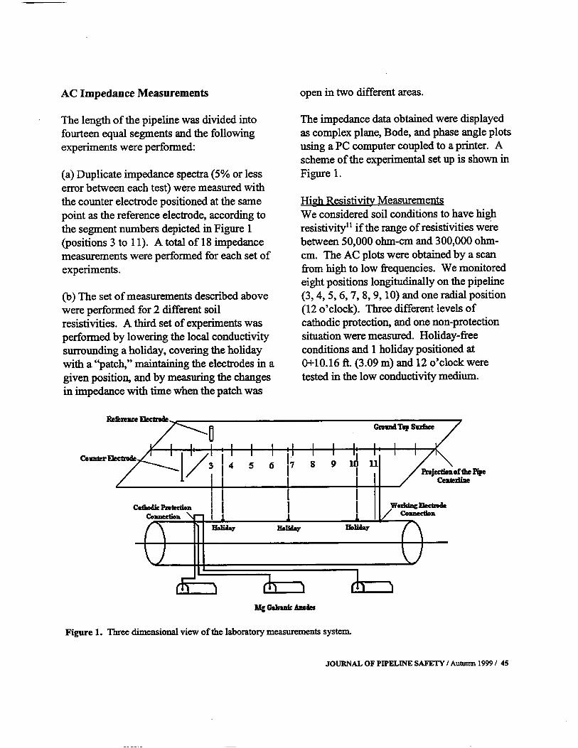
AC Impedance Measurements open in two different areas.The length of the pipeline was divided intofourteen equal segments and the followingexperiments were performed:a Duplicate impedance spectra 5% or lesserror between each test were measured withthe counter electrode positioned at the samepoint as the reference electrode, according tothe segment numbers depicted in Figure 1positions 3 to 11. A total of 18 impedancemeasurements were performed for each set ofexperiments.b The set of measurements described abovewere performed for 2 different soilresistivities. A third set of experiments wasperformed by lowering the local conductivitysurrounding a holiday, covering the holidaywith a "patch," maintaining the electrodes in agiven position, and by measuring the changesin impedance with time when the patch wasThe impedance data obtained were displayedas complex plane, Bode, and phase angle plotsusing a PC computer coupled to a printer. Ascheme of the experimental set up is shown inFigure 1.High Resistivity MeasurementsWe considered soil conditions to have highresistivity" if the range of resistivities werebetween 50,000 ohm-cm and 300,000 ohm-cm. The AC plots were obtained by a scanfrom high to low frequencies. We monitoredeight positions longitudinally on the pipeline3,4, 5,6, 7, 8, 9, 10 and one radial position12 o'clock. Three different levels ofcathodic protection, and one non-protectionsituation were measured. Holiday-freeconditions and 1 holiday positioned at0+10.16 ft. 3.09 m and 12 o'clock weretested in the low conductivity medium. MgC*b~nicAnode~Figure 1. Three dimensional view of the laboratory measurements system.JOURNAL OF PIPELINE SAFETY / Autumn 1999 / 45

Medium Resistivity MeasurementsMedium resistivities were between 10,000ohm-cm and 50,000 ohm-cm11. For these soilconditions, nine positions of the counter andreference electrode were monitored 3, 4, 5, 6,7, 8, 9, 10 and 11. An additional positionwas between the signal source and the pipelineworking electrode connection. This positionwas not considered before because theconnection may influence the measuredimpedance response when the soil has highresistivity. Holiday-free conditions, 1 holidaypositioned at 0+3.58 ft. 1.091 m, and 2holidays positioned at 0+3.58 ft. 1.091 mand 0+10.16 ft. 3.09 m were tested.Low Resistivity Measurements LocalizedConditionsThe impact of the holiday area on corrosionactivity was studied using local low resistivity500 ohm-cm surrounding the defect. Aholiday was exposed to 3% NaC1 electrolytethen a "a patch" was used to insulate this highconductivity medium from the surroundingsoil-environment medium resistivity, 10,000ohm-cm to 50,000 ohm-cm. A pinhole wasmade on the "patch" surface 5 days after thestart of the experiment area = 0.09 1 cm2.After 10 days of running the experiment, theinsulating cover on the defect was removedand the entire defect surface was exposed9.57 cm2.Results and Discussionwith constant length, diameter, and coatingthickness. The pipe was buried at a constantdepth and soil resistivity. The soil waschanged uniformly by adding water. For lowresistivity conditions when the run contained"an activated holiday", we changed localconditions by adding a solution containing 3%NaC1 around a holiday and covered the defectwith a "patch." We then first punched apinhole in the patch then pulled the patchcompletely off to expose the holiday. Thisexperiment aimed to "activate" a holiday fromthe corrosion point of view, so that we couldchange the soil resistivity later on. By"activate" we mean to induce localizedcorrosion activity.The pipe had 4 levels of cathodic protection:no protection, protection, under-protection,and over-protection. One or two defects wereconsidered simultaneously and the area of thedefects were different for each holiday.Summarizing, we present a discussion ofresults by measuring impedance data on asystem for which the variables were: inumber of holidays; ii soil resistivity; iiielectrode positionss; iv levels of cathodicprotection; v area of the holidays; vi timeof measurement; and vii severity ofcorrosion. Presenting the results of each ofthose variables is a task too long for thispaper, therefore we present the results of oneor more variables at a time.The information was obtained with EIS underdifferent environmental conditions. Forsimplicity, the results will be presented foronly four electrode positions 3, 4, 6 and 10.As we mentioned previously, we used a pipeNumber of Holidays and Soil ResistivityHoliday-free conditions, one holidaypositioned at 0+3.58 ft. and two holidayspositioned at 0+3.58 Ft. and 0+10.16 ft. weretested. The critical size of a holiday or acritical number of them is important for the46 / Autumn 19991 JOURNAL OF PIPELINE SAFETY

activity location of any defect in a pipeline.Figure 2a shows the sensitivity of theimpedance respOnse of the system to thenumber of holidays at the surface of thepipeline. The polarization resistance, Rp,decreases by lMohm at high soil resistivity60,000 ohm-cm when a holiday is open on athe pipe coating. At medium conductivity20,000 ohm-cm, we also observe a sharpdecrease in the polarization resistance when adefect is created on the pipe coating. Byincreasing the number of holidays more than1 no large changes are recorded, as shown inFigure 2b. b 1nP~ -o-*nc -*-a~ ac 0~ 1.c~BO6Electrode Position and the Presence of aHolidayFigures 3a and 3b show, for two differentsets of experiments, how impedance spectrachange with the position of the referenceelectrode for a pipeline without any holidaysand a holiday induced at the position 0+10/16ft. 3.09 m.The results shown in Figures 3a and bcorrespond to a system cathodically protected.The holiday-free situation exhibits for allpositions, the same semicircle shape withsimilar Rp on the Nyquist plot. When aholiday is present, the semicircle spectra shapebecomes smaller as the position of thereference electrode approaches the holidaylocation and the Rp decreases in magnitudecompared with a free-holiday situation.E2~00E~06t5OE~61.00E~65.00E~050.OOE.O0 0.0-500~5aoE.~1.~065~I~ -.- ~x -O-IK3X+00 1 .OOE.06 2.00E106z0hm Z a~mFigure 2a and b. Nyquist diagrams for high a and medium b soil resistivities as a function of the number ofholidays NH: no holidays, 111: one holiday, 2H: 2 holidays. The holidays are on the pipe coating at the 12 o'clockposition on the pipe circumference, and for the electrodes at position 3 along the pipe. The system is under-cathodically protected.JOURNAL OF PIPELINE SAFETY / Auturrm 1999/ 47

-4.-Point 3 -.--Point4 Point S -4~-- Point 6 -*-Point 7 .--Point 8 -I-- Point 9 -Point 10 5.OOE.05 20Hz -.--. ~int 3 -U-- Ri„it 4 ~8 5 - Fbi,t 6 -0---- Iblrd 7 -4.--- Runt 8 -18--- Ruint 9 -Ù---Ruiut 10 u.uu~4w - 0.0 ~00 l.OOE.06 2.OOE+06 _n ~Figures 3a and b. Impedance spectra for a high resistivity soil and free of holidays; and b 1 holiday at theposition 0+10.16', as a function of the position of the external electrodes. The system is cathodically protected-900mV vs. CuJCuSO4.Level of Cathodic Protection and SoilResistivityFigure 4 shows the impedance measurementsat high a and mediumb resistivity on a pipewithout open holidays and for which theelectrodes were placed in position 3. Thecharacteristics of the measured impedance, asexpected, change very dramatically with thelevels of cathodic protection. The maximumRp is obtained for an unprotected system andthe lowest for an over-protected system. Thistrend is independent of the soil resistivity, butthe effect semicircle Rp is amplified if thesoil resistivity is higher. When no cathodicprotection is applied, the coating/metalinterface works as a RC system, while the soiland pipe can be represented as a purelyresistive system. The overall result is asemicircle which can be represented as atransmission line for which all elements arethe same if no holidays are present on thepipeline coating. The total Rp corresponds tothe equivalent RC circuit representing thetransmission line. If the system iscathodically protected, we force the electronsto travel from the sacrificial anodes to theprotected pipe, converting the pipe on thecathode of the system. When a potential dropis applied between the working electrodeJipe and the reference electrode soil, anadditional source of electrons on the pipe mustbe considered, resulting in a lower Rp value ofthe equivalent RC circuit. The results of theimpedance will depend also on the soil andpipe resistivities. Because the pipe resistivityremains the same throughout themeasurements, only changes in soil resistivityare reflected on the results.It is important to notice that the level ofcathodic protection on the pipe system has animportant effect on the sensitivity of detectingthe activities of holidays.abEN2~0E+062.OOE.061.500*061.000*062.0064061.5064061.00E065.0064050.OOE*00 0.00-5.006405E0p~I 85Hz*00 1.000*06 2.506406z. ~y~rohm48 / Autumn 1999/JOURNAL OF PIPELINE SAFETY

a bETime and Soil ResistivityFigure 5 shows the variations in theimpedance's between the pipeline at locallylow resistivity conditions and mediumhomogeneous. soil resistivity as a function oftime. The impedance spectra shows semi-E 1.00E406N 5.00E405circles of large diameters on the first days 1-5, with a diffusion-like behavior little tail atlow frequencies less than 10mHz. At day 5a pinhole was made on the "patch" coatingcovering the active holiday. We immediatelydetected a lower Rp value.2.00E906I .50E406 -0-- NP3X * UP3X -0-- OP3X400 I.00E406 2.005406Z' o~im 0.00 -5.005405 rohmFigure 4a and I,. Impedance spectra for a medium and b high soil resistivity with no holidays and 4 levelconditions of cathodic protection NP: No protection, UP: Under-protection, CP: Cathodic protection, and OP:Overprotection for electrodes in position 3.ab -,-~yi -.o.-~y 3 -o-~y4 -o-~y5 ~y 10 -+-I~y 11 -~y12 0.0 .~ l~ .AN~.fltFigure 5a and 5b. Nyquist diagrams for medium soil resistivity and low local resistivity as a function of time atelectrode positions 4a and position 6b. A "patch" was sealing the holiday. The patch was opened to an area of0.019 cm2 after 5 days and to 9.57 cm2 after 10 days.r~0hnJOURNAL OF PIPELINE SAFETY / Autumn 1999 / 49

During days 6 to 10, the resistivity of thehomogeneous soil and local medium wereexposed provoking the Rp value to increase.Table I summarizes the Rp and Cdl calculatedfrom the impedance measured as a function oftime. Rp started to increase from day six,when the soil started to dry due to waterevaporation into the atmosphere, anddrastically diminished at day 10 when theholiday was totally exposed to theenvironment.The Rp decreases slightly Figure 6a, andTable I as does Cdl, Figure 6b and Table Ifrom days one to five. This decrease is aresult of a change in the soil conditions afterthe addition of water. On the fifth day of theexperiment, a pinhole was made on thecoating of the patch sealing the active defectfor which a 3% NaC1 electrolyte was locallyadded under the patch. The Rp decreasedsharply. The Cdl Figure 6 b does not showany important change at day 6. At the end ofday 10, the patch that covered the active defectwas removed. Rp decreases sharply and theCdl change is detected because the surface ofthe holiday is now much larger. Days Potential MV 1 -900 3 -901.6 4 -899.8 5 -899.6 6 -898.5 8 -899.9 10 -885.4 11 -898.7IZI1HZ Rp Ohm1 .85E+051 .84E+051.77E+051 .77E+056.49E+047.11 E+049.05E+047.55E+02OLow~Hz8.1618.1618.1618.16154.3654.3654.3621.06 Cdl F1.15E-081 .29E-081 .38E-081 .52E-081.13E-081.13B-081 .25E-081.13E-03coHz2411241124112411387538753875225.41.85E+0522543.441.82E+0522543.571.75E+0522543.791.73E+0522543.644.25E+0422542.148.93E+0422542.291.06E+0522542.88Table I. Electrochemical impedance spectroscopy parameters for the time-dependentmeasurements. Cathodically under-protected pipeline, electrodes in position 4, and mediumresistivity of the soil and locally low resistivity under the isolate holiday.50 / Autumn 1999/ JOURNAL OF PIPELINE SAFETY

I.OOE+05-c00. 5.OOE+04From the results shown so far, it is clear thatdifferences in impedance signatures areobtained if the level of protection changes or ifa holiday is present and becomes active. Lessobvious is the fact that from one run toanother, we will not be able to say if a priori ifthe observed changes are due to corrosionactivity. We can neither say where thatactivity is located, nor what the severity is ofthat activity. In order to explore whether thesethings are possible, we need to further analyzethe data gathered, and perhaps we will need tochange the representation of the data fromNyquist and Bode diagrams to something else.Because each one of the signaturesrepresenting the impedance contains severalpoints, we decided to change the datarepresented by the Nyquist and Bode diagramsto a more compact form so that we couldcapture all the measured changes ofimpedance on the system. For example, weplotted the Nyquist diagrams for each run andcalculated the Rp and Cdl and the frequenciesat which those values occurred. Similarly, onthe Bode diagrams, we calculated the breakingpoints and slope of the curve plotted from thedata measured and listed those values and thecorresponding frequencies at which theyoccurred.In this way, the n-points used to measure theimpedance the whole range of frequenciesgives us a 3n vector size with n frequencies, nimaginary and n real impedancemeasurements are compressed to a shortervector of 12. That vector contains the Rp, ~frequency corresponding to that Rp, Cdl andcorresponding o frequency, slope of theBode Phase angle and slope of the BideMagnitude, corresponding frequencies, andthe breaking points of the slope break at theBode Phase angle and Magnitude and itscorresponding frequencies.In addition to the variables defined, we addeda b2.OOE+05I .50E+05-0-Poskion 4X~-a-- Position 6X1O.OOE+OO 1.OOE.03 ia&oi I.Oos-~ 1.OOE.06 1.OO&07 1.WE.O8 -5.OOE+04 1.OOE-09 Time DaysFigures 6a and b. Changes of measured Rp a and Cdl b with time for electrode positions 4 and 6. The soilresistivity was maintained at a fixed medium value. A patch was sealing the holiday. The patch was opened to anarea of 0.019 cm2 after 5 days and to 9.57 cm2 after 10 days.Turn Days0 2 4 6 8 10 12 14JOURNAL OF PIPELINE SAFETY/Autumn 1999 / 51

as variables all those parameters that set thepipe environment. Those variables includesoil resisitivity, soil pH, ambient temperature,pipe diameter, pipe depth, coatingcharacteristics, electrode positions withrespect to a reference, and level of cathodicprotection or polarization voltage.We decided to use a pattern recognitionanalysis to establish the hidden relationshipbetween the input signatures and the data thatwe were interested in predicting. Thatpredicted data or output vector contains theinformation that we want to obtain; thisinformation is used to train an artificial neuralnetwork pattern recognition system. Once thenet learns to relate inputs to outputs, theoutput vector is not shown any more and thepattern recognition tool is expected to indicatethe output vector for a given input vector. Inthis way, we expect to be able to establish thelocation of the defects and to assess theseverity of the damage.Neural Networks ModelWe designed a net with 3 layers eachcontaining 50 neurons. Each neuron had ahyperbolic tangent transfer function. Wechose a Delta rule with momentum to updatethe weights.The net was trained with 250 runs. Each runcorresponded to a full impedancemeasurement of a well-characterized system.We had 17 inputs corresponding to thecharacteristics of the Nyquist and Bodediagrams as described. General informationsuch as soil resistivity, pH, temperature,electrode position from the end of the pipe,etc. was also included. The outputs werenumber of holidays, area of holidays, positionof holidays, and severity of damage in a scalefrom Oto 100.We developed the net on a commercial shelland we trained it on a PowerMacÆ for over 26hours. We stopped training when the errorwas oscillating between 1 and 5%. To test theaccuracy of the results we tested the net ondata that was used for training, and for whichwe knew a priori the correct resultant vectornumber of holidays, position of holidays, areaof holidays and severity of damage.Figure 7 shows the measured horizontaldistance in feet and measured over the groundand along the pipe axis from the electrodes toone holiday on the underground pipe coatingversus the Neural Networks NN predicteddistance. If the NN predictions were perfect,we would expect a straight line. The resultsshow that the NN can predict the position ofthe active holiday with an error oscillatingabout 5%, which corresponds to the estimatedmeasured error.Figure 8 shows a similar result to those shownin Figure 7, but for a two-holiday system. Theerrors obtained on the prediction of the NN areabout the same size of the error introduced bymeasurements 5%. At this point in time, justa few two-hole systems have been measured.52/ Autumn 1999 / JOURNAL OF PIPELINE SAFETY
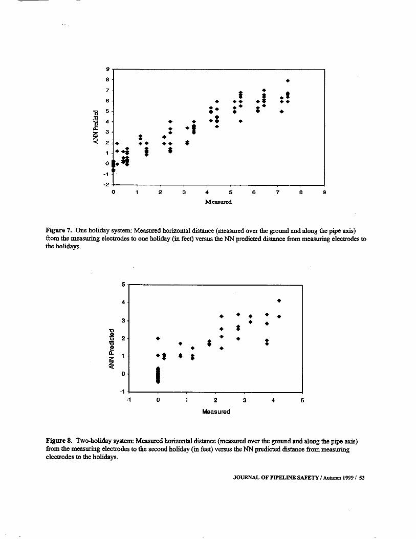
a 8 7 t 6 * ** ** ** *. ** .* *g5 S S * 4 . . * a * z * * z * . C 2~ ** ** $ 1 $ 0.11 -2 0 1 2 3 4 5 6 7 8 9 MeasuredFigure 7. One holiday system: Measured horizontal distance measured over the ground and along the pipe axisfrom the measuring elecirodes to one holiday in feet versus the NN predicted distance from measuring electrodes tothe holidays. 5 4 5 * ** ** 3 5 5 V S * S * $ o * * *~ S 1 V $ 0 -1 0 1 2 3 4 5 MeasuredFigure 8. Two-holiday system: Measured horizontal distance measured over the ground and along the pipe axisfrom the measuring electrodes to the second holiday in feet versus the NN predicted distance from measuringelectrodes to the holidays. JOURNAL OF PIPELINE SAFETY I Autumn 1999 / 53

Figure 9 shows the capability of the net inpredicting the severity of the damage on ascale of 0 to 100 arbitrary scale. The netperforms very well in separating the mildcorrosion from the severe corrosion. The netcorrectly predicts more accurately the higherlevel of corrosion severity 100 than lowerlevels of corrosion severity 0. This may bedue to the way we defined our scale for C- zIt is important to mention that we used a 3-layer forward-backward propagation withhyperbolic tangent transfer function, whichsuccessfully predicts the location of theholiday on the pipe. The level of damage onthose holidays indicates that the relationshipbetween inputs and outputs is highly non-linear. We also investigated which inputparameters contributed most to the learning.Exploring the values of the weights thatconnect the neurons from the results down tothe inputs, we found that the frequency atwhich Cdl is measured is a very importantcorrosion severity. We assigned a zerocorrosion rate when we visually did not noticechanges on the metal surface exposedthroughout the holiday while it was exposed tothe environment. It is important to notice thatthe net easily predicts the high severity cases,which are of more interest from anengineering and reliability point of view.variable to detennine the distance at which theholiday is located. However, if we plot thatvariable versus the distance at which theholidays are located, we do not find any linearor non-linear correlation. This confinns thefact that 3 layers of neurons were needed tocapture the relationships between inputs andoutputs. In other words, this confirms thehighly non-linear relationships between inputsand outputs.$. 120 100 80 60 40 20 0 -20 -20 0 20 40 60 80 100 120 MeasuredFigure 9. One holiday system: Measured corrosion severity versus NN predicted corrosion severity.1~54 / Autumn 1999/ JOURNAL OF PIPELINE SAFETY

ConclusionsThe ANN showed that it learned how topredict a holiday's location, size, and severityof corrosion on a single and double holidaysystem, and at several levels of cathodicprotection PSU Patent filed. The data werepresented to the net, randomly shuffled, andthe net learned to predict the severe swings ofthe input variables. When presented, inputdata to the net changed from one to thefollowing run, because each row on the inputmatrix represents a completely newexperimental run. In "real life", systems arenot expected to have big swings; they willchange in the way that the holiday willdevelop. Accordingly, we expect that a net -which can be implemented in place forcontinuous monitoring of the system - will beable to predict changes in the impedancesystem due to the corrosion activity on thepipe with more accuracy. The small changeson the magnitude and phase angle break-points and slopes on the Bode diagram used torepresent the AC impedance continuousmeasurements will be used to predict thelocation of the holidays, and their corrosionReferences1. US Department of Transportation, PipelineSafety Regulations, Natural Gas Part 19 1-192,p. 390-394.2. M. Kending, F. Mansfeld and S. Tsai,"Determination of the Long Term CorrosionBehavior of Coated Steel with AC ImpedanceMeasurements," Corrosion Science, 23, 4,1983.severity. In the examples presented to the net,in this study, the soil-to-pipe polarization wasmeasured and it was used as input. Wepreviously demonstrated that a similaranalysis can be used to assess the level ofcathodic protection in underground pipelines.Accordingly, we anticipate that the level ofcathodic protection can be used as an output ofthe system and therefore allow the net topredict them. We are searching for anopportunity in the near future to test ourpredictive system in a large "real life" sizesystem under several levels of cathodicprotection and several ground fieldresistivities.AcknowledgmentsHomero Castaneda gratefully acknowledgesthe financial support of DGAPA from theNational University of Mexico UNAM, andthe authors acknowledge Mrs. Ayako Yajimafor her help in the experimental set up.3. M.E. Orazem, J.M. Esteban, K.J. Kennelly,and R.M. Degerstedt, "Mathematical Modelsfor Cathodic Protection of an UndergroundPipeline with Coating Holidays: Part 1 -Theoretical development," Corrosion, 53, 4,1997.4. M.E. Orazem, J.M. Esteban, K.J. Kennelly,and R.M. Degerstedt, "Mathematical Modelsfor Cathodic Protection of an UndergroundPipeline with Coating Holidays: Part 2 - CaseStudies of Parallel Anode Cathodic ProtectionJOURNAL OF PIPELINE SAFETY / Autumn 1999 I 55

Systems," Corrosion, 53, 6, 1997.5. M.E. Orazem, K.J. Kennelly, and L. Bone,"Current and Potential Distribution on aCoated Pipeline with Holidays Part II -Comparison of the Effects of Discrete andDistributed Holidays," Corrosion, 49, 3,1993.6. F. Mansfield, L.T. Han, C.C. Lee and G.Zhang, "Analysis of ETS and ENA Data forPolymer Coated Steel Exposed at RemoteTest," Materials Science Forum, 247, 51,1997.7. F. Mansfield and C.H. Tsai,"Determination of Coating Deterioration withETA: Part II. Development of a Method forField Testing of Protective Coatings,"Corrosion, 49, 9, 1993.8. P.R. Roberge and V.S. Sastri, "On LineCorrosion Monitoring with ElectrochemicalImpedance Spectroscopy," Corrosion, 50, 10,1994.9. M.C.H. McKubre, S.C. Leach, D.D.Macdonald and S. Hettiarachi, A Study ofFeasibility of Using Electrical Methods toDetect Defects in the Coatings of CathodicallyProtected Pipelines," Final Report Project8601 by SRI 1986.10. Y.A. El-Tantawy, R.C. Rocha-Filho, M.Urquidi-Macdonald and D.D. Macdonald,"Development of Ultralow Frequency ACImpedance Spectroscopy ULFACIS forDetecting and Locating Corrosion on Rebar inReinforced Concrete," Final Report by SRIunder contract SHRP-87-1D008 1989.11. D.C. Silverman, "Artificial NeuralNetwork Predictions of Degradation ofNonmetallic Lining Materials from LaboratoryTests," Corrosion, 50,6 1994.12. J. Morgan, Cathodic Protection, NationalAssociation of Corrosion Engineers, P. 27Houston, TX, 1987.13. D.D. Macdonald, I. Balachov, J. Sikora,and 1. Kriksunov, and M. Urquidi-Macdonald.Final Report: New Technique to AssessLevels of Cathodic Protection in UndergroundPipe Systems Phase I and II. ThePennsylvania State University. February 291996.Dr. Mirna Urquidi-Macdonald is currently writing of two books on energy relatedan Associate Professor, Engineering Science matters. She was also a senior researchand Mechanics at Penn State University. She scientist at the Stanford Research Institute. Inholds a Ph.D in plasma physics from the 1994, she was appointed by the Secretary ofUniversity of Paris XI, Orsay, France and has Transportation to serve on a Pipeline Safetydone Postdoctoral studies in plasma physics at Advisory Committee.the Pierre Marie Curie Lab, University ofParis VI. Mima has published over 140 H. Castaneda is a graduate student at Pennscholarly papers and participated in the State University.56 / Autumn 1999 / JOURNAL OF PIPELINE SAFETY

OPS Regulatory Agenda Watch JPS Staff An overview of the Pipeline Safrty regulatory agenda is presented here to enable interested parties to prudently plan their pipeline safety regulatory compliance efforts. A key item for trackingforthcomingfinal rulemakings is discussed along with suggestions for monitoring progress on other agenda items. Another purpose served is that of providing JPS authors with a common base ofpending issues and how best to comply effectively and efficiently.DescriptionThe latest Department of Transportation Semiannual Regulatory agenda wasissued on November 22, 1999 64 FR 64851.The agenda includes the Office of PipelineSafety's Research and Special ProgramsAdministration semiannual summary of allcurrent and projected rulemakings, reviews ofexisting regulations, and completed actions.These are matters on which action has begunor is projected during the succeeding 12months, or such longer period as may beanticipated~ or for which action has beencompleted since the last agenda. The agendasare based on reports submitted by the officesinitiating the rulemaking and are reviewed bythe Department Regulations Council. TheDepartment's last agenda was published in theFederal Register on April 26, 1999 64 FR21566. The next one is scheduled forpublication in the Federal Register in April2000.Purpose of the AgendaThe Department of Transportation states thatthe agenda provides the public and regulatedindustry with information about the Office ofPipeline Safety's regulatory activity. TheDepartment of Transportation expects that thisinformation will enable interested parties to bemore aware of and allow it to moreeffectively participate in the agency'sregulatory activity.The Department also notes that the agendadoes not impose any binding obligation on theagency with regard to any specific item on theagenda. Regulatory action, in addition to theitems listed is not precluded.DOT has created an Internet site that providesgeneral information about its rulemakingresponsibilities and activities. It includeshypertext links to numerous otherdepartmental sites providing helpfulJOURNAL OF PIPELINE SAFETY / Autumn 1999/ 57

information about DOT regulation. The webaddress for this site is http://regs.dot.gov.How Rulemakings Are DesignatedSignificant/PriorityThe agency has classified rules as a DOTagency priority in the agenda if they are,essentially, very costly, controversial, or ofsubstantial public interest under ExecutiveOrder 12866. All DOT agency priorityrulemaking documents are subject to reviewby the Secretary of Transportation. If theOffice of Management and Budget 0MBdecides a rule is subject to its review, it isclassified as significant in the agenda.Explanation of Information on the AgendaThe format for this agenda is required byOffice of Management and Budgetmemorandum of July 21, 1999. First, theagenda is divided by initiating offices. Then,the agenda is divided into five categories: 1prerule stage, 2 proposed rule stage, 3 finalrule stage, 4 long-term actions, and 5completed actions. For each entry, the agendaprovides the following information: 1 Its"significance"; 2 a short descriptive title; 3its legal basis; 4 the related regulatorycitation in the Code of Federal Regulations;5 any legal deadline and, if so, for whataction e.g., NPRM, final rule; 6 anabstract; 7 a timetable, including the earliestexpected date for a decision on whether totake the action; 8 whether the rulemakingwill affect small entities and/or levels ofgovernment and, if so, which categories; 9whether a Regulatory Flexibility Act RFAanalysis is required for rules that would havea significant economic impact on a substantialnumber of small entities; 10 a listing of anyanalyses an office will prepare or has preparedfor the action with minor exceptions, DOTrequires an economic analysis for all itsrulemakings.; 11 an agency contact office orofficial who can provide further information;12 a Regulation Identifier Number RINassigned to identif~' an individual rulemakingin the agenda and facilitate tracing furtheraction on the issue; 13 whether the item ispart of the Reinventing Government effortand, if so, whether it would revise existingtext in the Code of Federal Regulations oreliminate text; 14 whether the action issubject to the Unfunded Mandates Act; and15 whether the action is major under thecongressional review provisions of the SmallBusiness Regulatory Enforcement FairnessAct. If there is information that does not fit inthe other categories, it will be included undera separate heading entitled "AdditionalInformation."In the "Timetable" column, DOT usesabbreviations to indicate the particulardocuments being considered. ANPRM standsfor Advance Notice of Proposed Rulemaking,SNPRM for Supplemental Notice of ProposedRulemaking, and NPRM for Notice ofProposed Rulemaking. Listing a future date inthis column does not mean OPS has made adecision to issue a document; it is the earliestdate on which they expect to make a decisionon whether to issue it. In addition, these datesare based on current schedules. Informationreceived subsequent to the issuance of thisagenda could result in a decision not to takeregulatory action or in changes to proposedpublication dates. For example, the need for58 / Autumn 1999/ JOURNAL OF PIPELINE SAFETY

further evaluation could result in a laterpublication date; evidence of a greater needfor the regulation could result in an earlierpublication date.Guidelines for Determining ForthcomingFinal RulesA key indicator that generally predicts that arulemaking is forthcoming as a final rule is avote on the issue by the Safety AdvisoryCommittees. The Technical HazardousLiquid Pipeline Safety Standards CommitteeLiquids and the Technical Pipeline SafetyStandards Committee currently meet twice ayear, usually in May and November. It isduring these meetings that items are placed onthe agenda for discussion and in some cases avote on the technical feasibility,reasonableness, and practicability of theproposal is recorded. Once the committeesvote on the rulemaking, the way is cleared forfinal rule publication soon thereafter in thefederal register.Under the Committees charters, its objectivesand duties are as follows:The Executive Director shall submit to theCommittee for its consideration any notice ofproposed hazardous liquid pipeline safetystandards, or gas pipeline safety standardspublished in the Federal Register. Within 90days after receipt by the Committee of anysuch proposal, the Committee shall prepare areport on the technical feasibility,reasonableness, and practicability of theproposal.Each report by the Committee, including anyminority views, shall if timely made, form apart of the proceedings for the promulgationof the standard and be incorporated in thepreamble published with the final rule in theFederal Register. The RSPA Administratormay prescribe a final standard at any timeafter the 90th day following a proposal'ssubmission tot he Committees, whether or notthe Committee has reported on such proposal.The Administrator shall not be bound byconclusions of the Committee, but in the eventthat the conclusions of the majority of thecurrent members of the Committee arerejected, the reasons for rejection shall also beincorporated in the preamble of the final rule.Application of the Committees VotingFactor GuidelineThe Office of Pipeline Safety usually givesnotice of each committee meeting in theFederal Register at least 15 days in advance ofthe meeting, except in emergency situations.The Federal Register notice usually sets outthe authority for the meeting and a tentativeagenda. If a proposed rulemaking is to bediscussed and voted on by the committee itmay or may not be indicated in the federalregister notice. Items designated for a vote arecurrently announced or noted at the actualcommittee meeting.For example, on April 1, 1999 OPS issued afederal register notice 64 FR 15869announcing the Safety Advisory Committeesmeeting for May 4-5, 1999. The agenda noteda discussion on the following, among otheritems:Gas and Hazardous Liquid PipelineRepair - an OPS proposed rulemakingJOURNAL OF PIPELINE SAFETY I Autumn 1999 / 59

On May 4th, 1999, the Committees met inWashington, D.C. and did in fact note thisitem as a vote issue. Both committees votedunanimously to approve the proposed rule,"Gas and Hazardous Liquid PipelineRepair." This item was subsequently issuedby OPS as a Final Rule on December 4th,1999 in the federal register. If a rulemaking isdesignated as "Significant" the time periodbetween committee vote and final rulepublication may be affected by Office ofManagement and Budget review.A reading of the Safety Advisory Committeemeeting minutes or attendance, or contactingthe OPS person dealing with a particularrulemaking is necessary to monitor issuesselected for a vote. There are two otherconsiderations regarding the committee votingissue. One, is that direct final rules may ormay not require a formal committee vote.Secondly, the use of mail ballots to canvassthe committee's response to a particular issuedoes not necessarily have to be reported at ascheduled committee meeting.Suggestions for Monitoring Progress onAgenda ItemsThere are currently 20 rulemaking items onthe OPS agenda. A simple and easy way tomonitor developments on each item is to makeuse of the OPS website: http://ops.dot.gov andgo to the "OPS Regulations" link and note the"OPS Regulations Index" and then to the"Rulemaking Summaries". OPS is currentlyupdating these summaries on a regular basis.A backup system for making sure that finalrules are posted accurately on the OPS websiteis to verify all entries with the CFR LSAavailable from the Government PrintingOffice both in paperback and online.An alternative way of tracking changes to theagenda is to monitor the "Regulatory AgendaWatch" of the Journal of Pzpeline Safety every6 months and track committee vote status oneach item as well.The Current Agenda - Quick UpdateA quick update on the regulatory agenda interms of significant and non significant itemsby category: Gas 49 CFR 192, Liquids 49CFR 195 and Both Gas and Liquids 49 CFR190-199 inclusive proposed rulemakings ispresented below: OPS Regulatory Agenda Onick Update Source: 64 FR 64851:11/22/99I. 0 Gas 49 CFR 192 Rulemaking IProposed StagelNon NS S Date ofSignificant Significant Committee VoteGas Gathering Line Definition NSFurther Regulatory Review; Gas Pipeline Safety Standards NS60/ Autumn 1999 / JOURNAL OF PIPELINE SAFETY

11.0 Gas 49 CFR 192 Rulemaking IFinal StagelDetermining the Extent of Corrosion on Exposed NS Sept 12, 1989Gas Pipelines March 1999 Note: Final Rule issued 10/22/99; 64 FR 56978Adoption of Indusiry Standards for Liquefied Natural NS May 5, 1999Gas Facilities111.0 Liquids 49 CFR 195~ Rulemaking EProDosed StagelAreas Unusually Sensitive to Environmental Damage NSUSAS+Emergency Flow Restricting Devices S+Recoxnmendations to Change Hazardous Liquid SPipeline Safety StandardsPressure Testing Older Pipelines in Terminals NSIV.0 Liquids 49 CFR 195~ Rulemaking IFinal Stagel+Response Plans for Onshore Oil Pipelines SV.0 Gas and Liquids 49 CFR 190-199 Rulemaking IProposed StagelPeriodic Underwater Inspections NSProducer-operated Outer Continental NSShelf Gas and Hazardous Liquid PipelinesThat Cross Directly Into State WatersPeriodic Updates to Pipeline Safety NSRequirements 1999Corrosion Control on Gas and Hazardous NSLiquid PipelinesGas and Hazardous Liquid Pipeline Repair NS May 4, 1999 Note: Final Rule 12/14199; 64 FR 69660VI.0 Gas & Liquids 49 CFR 190-199 Rulemaking EFinal StagelPassage of Internal Inspection Devices NS JOURNAL OF PIPELINE SAFETY / Autumn 1999/ 61

+Maps and Records of Pipeline Locations and SCharacteristics; Notification of State Agencies;Pipe InventoiyUnderwater Abandoned Pipeline Facilities NS Nov 5, 1999Enforcement Procedures NS Nov 5, 1999Vll.0 Gas 49 CFR 192 ILong Term Action StagelXllI.O Liquids 49 CFR 1951 ILong Term Action StagelIX.0 Gas & Liquids 49 CFR 190-199 ILong Term Action Stagel+Increased Inspection Requirements SRegulated Gas and Hazardous Liquid NSGathering Lines The Regulatory Agenda of the Office of Pipeline Safety Source: 64 FR 64851 ~1 1/22/99Proposed Rule Stage1.0 GAS GATHERING LINE DEFINITION [Proposed Rule Stage]Priority: Substantive, NonsignificantLegal Authority: 49 USC 60101 to 60125CFR Citation: 49 CFR 192Legal Deadline: Final, Statutory, October 24, 1994.Abstract: The existing definition of "gathering line" would be clearly defined to eliminateconfusion in distinguishing these pipelines from transmission lines in rural areas. The costs shouldbe minimal since the definition will conform to prevailing practices in government and industry.62/ Autumn 1999/ JOURNAL OF PIPELINE SAFETY

Timetable:Action Date FR CiteNPRM 09/25/91 56 FR 48505Request for Comments 03/11/99 64 FR 12147Electronic Public Meeting 04/13/99Extension of Comment Period 04/30/99 64 FR 23256Comment Period Ends 07/07/99SNPRM 01/00/00Regulatory Flexibility Analysis Required: NoSmall Entities Affected: BusinessesGovernment Levels Affected: NoneAdditional Information: Docket No. RSPA-98-4868 Formerly PS-.122.ANALYSIS: Regulatory Evaluation, 09/25/9 1, 56 FR 48505Agency Contact: L.E. Herrick, Transportation Specialist, Department of Transportation, Researchand Special Programs Administration, 400 Seventh Street SW., Washington, DC 20590.Phone: 202 366-5523RJN: 2137-AB152.0 AREAS UNUSUALLY SENSITIVE TO ENVIRONMENTAL DAMAGE USAS[Proposed Rule Stage]Priority: Substantive, NonsignificantLegal Authority: 49 USC 60101 to 60125CFR Citation: 49 CFR 195Legal Deadline: Final, Statutory, October 24, 1994. JOURNAL OF PIPELINE SAFETY / Autumn 1999 / 63

Abstract: In response to a statutoly mandate, this action will establish criteria for identifying areasnear hazardous liquid pipelines that are unusually sensitive to environmental damage if apipeline accident occurs. The criteria are being developed in consultation with the EnvironmentalProtection Agency and other agencies. Criteria for identification of unusually sensitive areas willbe pilot-tested in 1999.Timetable:Action Date FR CiteSupplemental Notice 06/22/94 59 FR 32178Extended Comment Period End 06/26/95NPRM 12/00/99Regulatory Flexibility Analysis Required: NoSmall Entities Affected: BusinessesGovernment Levels Affected: NoneAdditional Information: Docket No. PS-140. Was originally Docket PS-130B, "EnvironmentallySensitive Areas," for part 194. Changed to address part 195. A series of public workshops wereconducted in 1996 and 1997. Additional workshops will be scheduled as necessary. Pilottesting of USA guidance is now underway in cooperation with the American Petroleum Institute.Agency Contact: Christina Sames, Petroleum Engineer, Department of Transportation, Researchand Special Programs Administration, 400 Seventh Street SW., Washington, DC 20590Phone: 202 366-4561RIN: 2137-AC343.0 PERIODIC UNDERWATER INSPECTIONS [Proposed Rule Stage]Priority: Substantive, NonsignificantLegal Authority: 49 USC 60101 to 6012564 / Autumn 1999/ JOURNAL OF PIPELINE SAFETY

CFR Citation: 49 CFR 192; 49 CFR 195Legal Deadline: Final, Statutory, October 24, 1995.Abstract: This action would require operators of natural gas and hazardous liquid pipelines toconduct periodic underwater inspections of offshore pipelines and those in navigable waterways.This action would also define what constitutes an exposed underwater pipeline andwhat constitutes a hazard to navigation.Timetable:Action Date FR CiteNPRM 12/00/99Regulatory Flexibility Analysis Required: NoSmall Entities Affected: BusinessesGovernment Levels Affected: UndeterminedAdditional Information: Docket No. RSPA-97-3001.Agency Contact: Melaine Barber, Transportation Specialist, Department of Transportation,Research and Special Programs Administration, 400 Seventh Street SW., Washington, DC 20590.Phone: 202 366-4595RIN:2137-AC544.0 PERIODIC UPDATES TO PIPELINE SAFETY REOUIREMENTS 1999 [ProposedRule Stage] [New Item]Priority: Substantive, NonsignificantReinventing Government: This rulemaking is part of the Reinventing Government effort. It willrevise text in the CFR to reduce burden or duplication, or streamline requirements. JOURNAL OF PIPELINE SAFETY / Autumn 1999/ 65

Legal Authority: 49 Usc 60101 et seq.CFR citation: 49 CFR 190-199Legal Deadline: NoneAbstract: This periodic update revises and updates the pipeline safety regulations to provide clarityand remove unnecessary burdens to the regulated pipeline community. Revisions include updatedreferences to voluntary specifications and standards incorporated by reference in thepipeline safety regulations, and various clarifications and grammatical corrections. Thcse updatesreflect the most recent editions of each specification and standard incorporated by reference. Theseupdates enable pipeline operators to utilize current technology, materials, and practices, therebyreducing cost and enhancing economic growth.Timetable:Action Date FR CiteNPRM 12/00/99Regulatory Flexibility Analysis Required: NoSmall Entities Affected: NoGovernment Levels Affected: NoneAdditional Information: Docket No. RSPA-99-6 106Agency Contact: R. Huriaux, Manager - Regulations, Department of Transportation, Research andSpecial Programs Administration, 400 Seventh Street SW., Washington, DC 20590.Phone: 202 366-4565RIN: 2137-AD3566 / Autumn 1999/ JOURNAL OF PIPELINE SAFETY

Please accept this FREE sample copycourtesy of the publishers of theJournal of Pipeline Safety.We hope it has been of benefit to you.For subscription information or to order by phone orfax, $299/yr please call us at:phone/fax 1-888-720-8136 OR 202 637-9735e-mail wplbsa~agt.netTo order by mail, just send order card and payment$2991yr along with company, name, address andphone number to: Journal of Pipeline Safety do WPL P.O. Box 23675, L'Enfant Plaza Washington, DC 20026-3 675

Journal of Pipeline Safety P.O. Box 23675, L'Enfant Plaza Washington, DC 20026-3675 Phone/Fax 403 240-0171 E-mail: wplbsa~agt.net Enclosed is your first complimentary issue of the Journal of Pipeline Safety. We hope you will find the articles interesting and informative, and that they will be of benefit to you and your company. If you would like to continue to receivethe IPS, please fill out the form below and mail to: Journal of Pipeline Safety do WPL P.O. Box 23675, L'Enfant Plaza Washington, DC 20026-3675 OR, YOU CAN FAX THIS FORM TOLL FREE TO 1-888-720-8136. Our next issue will be Spring 2000, and is expected to be published in the late spring or early______ summer. _____ Thank you for expressing an interest in the Journal of Pipeline Safety. We welcome your comments or views at any time. JPS Staff o YES, I would like to continue to receive the Journal of Pipeline Safety. Yearly Fee: $299.00 2 issues, Spring and Autumn 2000 o Payment Enclosed 0 Bill my Company NATIONAL P/L REFORM COALITION ROBERT RACKLEFF PRESIDEI.~T 816 C~~RY STREET TAI.L~SSEE, FL 32303 Please make payment to Washington Pipeline Letter, and send to: Journal of Pipeline Safety, do WPL, P.0: Box 23675, L'Enfant Plaza, Washington, D.C. 20026-3675. Phone/fax 403 240-0171, or toll free, 1-888-720-8136.

5.0 CORROSION CONTROL ON GAS AND HAZARDOUS LIQUIDPIPELINES [Proposed Rule Stage]Priority: Substantive, NonsignificantReinventing Government: This rulemaking is part of the Reinventing Government effort. It willrevise text in the CFR to reduce burden or duplication, or streamline requirements.Legal Authority: 49 Usc 60101 to 60125CFR Citation: 49 CFR 192; 49 CFR 195Legal Deadline: NoneAbstract: The corrosion-control regulations for gas and hazardous liquid pipelines will be revisedto incorporate the latest safety standards for corrosion protection of steel pipe. Specific criteria forcorrosion protection will be incorporated into the federal pipeline safety regulations, including theadoption of voluntary standards of recognized standards-setting organizations, comparablestandards will be applied to both gas and hazardous liquid pipelines.Timetable:Action Date FR CiteNotice of Public Meeting 04/07/99 64 FR 16885NPRM Hazardous LiquidPipelines 12/00/99NPRM Gas Pipelines 02/00/00Regulatory Flexibility Analysis Required: NoSmall Entities Affected: NoGovernment Levels Affected: State, LocalAdditional Inlormation: Docket No. RSPA-97-2762. Notice of public meeting 10/29/97 62 FR56141.Agency Contact: L.M. Furrow, Manager, Regulations, Department of Transportation, Researchand Special Programs Administration, 400 Seventh Street SW., Washington, DC 20590.Phone: 202 366-4559 JOURNAL OF PIPELINE SAFETY / Autumn 1999/ 67

Email: gopala.vinjamuri~rspa.dot.govRIN: 2137-AD246.0 GAS AND HAZARDOUS LIOUID PIPELINE REPAIR [Proposed Rule Stage]Priority: Substantive, NonsignificantReinventing Government: This rulemaking is part of the Reinventing Government effort. It willrevise text in the CFR to reduce burden or duplication, or streamline requirements.Legal Authority: 49 USC 60101 to 60125CFR Citation: 49 CFR 195; 49 CFR 192Legal Deadline: NoneAbstract: Gas pipe that is generally corroded over a large area to the extent that wall thickness isunsafe must be replaced, unless in the case of transmission pipe, operating pressure is reduced.Similarly, any damage that impairs the serviceability of high-stress transmission pipe must bereplaced, unless it is repaired by a full encirclement welded split sleeve. The proposed rule wouldpermit operators to use alternative corrective methods that have been demonstrated to permanentlyrestore the pressure integrity of corroded or damaged pipe. By allowing the use of less expensiveproven technologies, the proposed rule would reduce costs in the gas pipeline industry withoutreducing safety.Timetable:Action Date FR CiteNPRM 04/07/99 64 FR 16882Comment Period Ends 06/07/99Final Rule 11/00/9968 / Autumn 1999/ JOURNAL OF PIPELINE SAFETY

Action Date FR CiteRegulatory Flexibility Analysis Required: NoGovernment Levels Affected: UndeterminedAdditional Infonnation: Docket No. RSPA-98-4733Agency Contact: L.M. Furrow, Manager, Regulations, Department of Transportation, Researchand Special Programs Administration, 400 Seventh Street SW., Washington, DC 20590.Phone: 202 366-4559Fax: 202 366-4566Email: [email protected]: 2137-AD257.0 PRESSURE TESTING OLDER PIPELINES IN TERMINALS [Proposed Rule Stage]Priority: Substantive, NonsignificantLegal Authority: 49 USC 60101 to 60125CFR Citation: 49 CFR 195.302Legal Deadline: NoneAbstract: Certain older pipelines in terminals and tank farms must be pressure tested beforeDecember 7, 2003. Based on a petition, RSPA is reconsidering this testing requirement in light ofthe risk and low operating stress of these pipelines. RSPA has stayed enforcement of the testingrequirement against pipelines designed not to operate above 20 percent of specified minimum yieldstrength.Timetable:NPRM01/00/00JOURNAL OF PIPELINE SAFETY / Autumn 1999/ 69

Action Date FR CiteRegulatory Flexibility Analysis Required: NoGovernment Levels Affected: UndeterminedAdditional Information: Docket No. RSPA-98-4316. Notice requesting comment 2/10/98 63 FR6677 in Docket No. PS-121.Agency Contact: Mike Israni, General Engineer, Department of Transportation, Research andSpecial Programs Administration, 400 Seventh Street SW., Washington, DC 20590.Phone: 202 366-4571Email: mike.israni~rpsa.dot.govRIN: 2137-AD268.0 +EMERGENCY FLOW RESTRICTING DEVICES [Proposed Rule Stage]Priority: Other SignificantLegal Authority: 49 USC 60101 to 60125CFR Citation: 49 CFR 195Legal Deadline: Final, Statutory, October 24, 1996.Abstract: This rulemaking would specify those circumstances under which operators of hazardousliquid pipelines are required to use emergency flow restricting devices EFRDs or otherprocedures, systems, and equipment to detect and locate pipeline ruptures and minimize releases.This action is considered significant because of substantial public interest.Timetable:ANPRM 01/19/94 59FR2802ANPRM Comment Period End 04/19/94NPRM 06/00/0070 / Autumn 1999 / JOURNAL OF PIPELINE SAFETY

Regulatory Flexibility Analysis Required: NoSmall Entities Affected: BusinessesGovernment Levels Affected: NoneAdditional Information: Docket No. PS-133. A public workshop was held on 10/19/95 60 FR44822. This action is being coordinated with other rulemakings on onshore oil spill response plansDocket No. PS-130; RIN 2137-AC3O, areas unusually sensitive to environmental damageDocket No PS-140; RIN 2137-AC34, and pipeline leak detection systems Docket No. RSPA 97-2362; RIN 2137-ADO5. These actions are being pursued in coordination with, and as part of theresponse to, the EFRD mandate.First, RSPA has required pipeline operators to develop and carry out onshore oil spill responseplans under the Oil Pollution Act of 1990 Docket No. PS-130; RIN 2137-AC3O. The operatorshave filed response plans under an interim final rule, and numerous tabletop exercises andarea exercises have been conducted to validate the planning process. Work is proceeding on a `oneplan' approach that would allow an operator to file only one oil spill response plan with the variousinterested agencies. A final rule will be directed toward improving operators' accident responsecapabilities and minimizing accident consequences.Second, RSPA published a proposed rule to adopt the American Petroleum Institute's APIpipeline leak detection system technical standard Standard API 1130, Computational PipelineMonitoring to guide industry implementation of computer-based leak detection systems DocketNo. RSPA-97-2362, RIN 2137-ADO6. This proposal would require that operators of hazardousliquid pipelines use API 1130 in conjunction with other information in the design, evaluation,operation, maintenance, and testing of their software-based leak detection systems. This will resultin a significant advancement toward the acceptance of leak detection technology on hazardousliquid pipelines. This is a necessary precedent to the possible adoption of regulations on emergencyflow restricting devices.Third, RSPA is working with the Environmental Protection Agency, the U.S. Coast Guard, andothers to develop a definition of "areas unusually sensitive to environmental damage from pipelinespills" Docket No. PS-140; RIN 2137-AC34. This effort will define areas that are candidates forthe application of EFRDs.Agency Contact: L. Ulrich, General Engineer, Department of Transportation, Research and SpecialPrograms Administration, 400 Seventh Street SW., Washington, DC 20590.Phone: 202 366-4556RIN: 2137-AC39 JOURNAL OF PIPELINE SAFETY / Autumn 1999 / 71

9.0 PRODUCER-OPERATED OUTER CONTINENTAL SHELF GAS AND HAZARDOUSLIQUID PIPELINES THAT CROSS DIRECTLY INTO STATEWATERS [Proposed Rule Stage] [New Item]Priority: Substantive, NonsignificantLegal Authority: 49 Usc 60101 et seqCFR Citation: 49 ~FR 192; 49 CFR 195Legal Deadline: NoneAbstract: This proposed rule would implement a provision of the December 10, 1996,Memorandum of Understanding MOU between the Department of the Interior DOT and theDepartment of Transportation DOT regarding Outer Continental Shelf OCS Pipelines. This rulewould address producer-operated pipelines that cross into State waters without first connecting atransporting operator's facility on the ocs. It is complementary to the Direct Final Rule DFRthat addressed OCS oil or gas pipelines located upstream of the points at which operatingresponsibility for the pipelines transfers from a producing operator to a transporting operator 62FR 61692, November 19, 1997; and 63 FR 126598, March 16, 1998. The proposed rule alsowould address the procedures by which producer and transportation pipeline operatorswould petition for permission to operate under either DOT or DOlregulations governing pipelinedesign, construction, operation, and maintenance according to the operational circumstances oftheir respective pipelines.Timetable:Action Date FR citeNPRM 03/00/00Regulatory Flexibility Analysis Required: NoSmall Entities Affected: NoGovernment Levels Affected: NoneAdditional Information: Docket No. RSPA-99-6 132.Agency contact: L.E. Herrick, Transportation Specialist, Department of Transportation, Researchand Special Programs Administration, 400 Seventh Street SW., Washington, DC 20590.72/ Autumn 1999/ JOURNAL OF PIPELINE SAFETY

Phone: 202 366-5523R1N: 2137-AD4210. FURTHER REGULATORY REVIEW: GAS PIPELINE SAFETY STANDARDS[Proposed Rule Stage]Priority: Substantive, NonsignificantReinventing Government: This rulemaking is part of the Reinventing Government effort. It willrevise text in the CFR to reduce burden or duplication, or streamline requirements.Legal Authority: 49 USC 60101 to 60125CFR Citation: 49 CFR 192Legal Deadline: NoneAbstract: This action would change miscellaneous gas pipeline safety standards to provide clarity,eliminate unnecessary or overly burdensome requirements, and foster economic change. Some ofthe proposed changes result from RSPA's further review of the standards following its 1995-1996review under the President's Regulatory Reinvention Initiative. Other changes are based onrecommendations by the National Association of Pipeline Safety Representatives NAPSR in itsNovember 1992 report on the standards. The proposed changes would reduce costs in the pipelineindustry without compromising safety.NAPSR and the pipeline industry fonned a working group to consider the NAPSR proposals andother issues. On May 3, 1999, this group submitted its evaluations of the proposed changes in thegas pipeline safety regulations.Timetable:Action Date FR CiteNPRM 12/00/99JOURNAL OF PIPELINE SAFETY / Autumn 1999/ 73

Action Date FR CiteRegulatory Flexibility Analysis Required: NoSmall Entities Affected: BusinessesGovernment Levels Affected: NoneAdditional Information: Docket No. PS-124. The NAPSR report was published November 9, 1993,at 58 FR 59431, as part of the earlier review of the standards.Agency Contact: Richard Huriaux, Director, Technology & Regulations, Department ofTransportation, Research and Special Programs Administration, 400 Seventh Street SW.,Washington, DC 20590.Phone: 202 366-4565RIN: 2137-ADO1 ____________ii. +RECOMMENDATIONS TO CHANGE HAZARDOUS LIOUIDPIPELINE SAFETY STANDARDS [Proposed Rule Stage]Priority: Other SignificantUnfunded Mandates: UndeterminedLegal Authority: 49 USC 60101 to 60128CFR Citation: 49 CFR 195Legal Deadline: NoneAbstract: In 1995, the National Association of Pipeline Safety Representatives NAPSRcompleted its review of the hazardous liquid pipeline safety regulations. NAPSR provided RSPAwith 28 recommendations for changes to 49 CFR part 195, the hazardous liquid pipelineregulations. NAP SR's recommendations are aimed at making the regulations more explicit,understandable, and enforceable. This action would address the need to change Part 195 as NAPSRrecommended.Timetable:NPRM09/00/0074 / Autumn 1999 / JOURNAL OF PIPELINE SAFETY

Regulatory Flexibility Analysis Required: NoSmall Entities Affected: BusinessesGovernment Levels Affected: NoneAdditional Information: Docket No. RSPA-97-2717.Agency Contact: L. M. Furrow, Transportation Specialist, Department of Transportation, Researchand Special Programs Administration, 400 Seventh Street SW., Washington, DC 20590.Phone: 202 366-4559RIN: 2137-AD1OFinal Rule Stage12. DETERMINING THE EXTENT OF CORROSION ON EXPOSED GAS PIPELINES[Final Rule Stage]Priority: Substantive, NonsignificantLegal Authonty: 49 USC 60101 to 60125CFR Citation: 49 CFR 192Legal Deadline: NoneAbstract: Gas pipeline operators must now inspect for corrosion on buried metallic pipe that isexposed by excavation. If any corrosion is discovered, this rulemaking would require operators toinvestigate further to determine the full extent of the corrosion. A similar investigation is alreadyrequired for hazardous liquid pipelines. NTSB has recommended that this proposal be adopted toestablish an equivalent level of safety for gas pipelines. In light of NTSB interest, this rule will befinalized, and other corrosion issues will be addressed in a separate rulemaking.Timetable:Action Date FR CiteNPRM 06/27/89 54 FR 27041 JOURNAL OF PIPELINE SAFETY / Autumn 1999 / 75
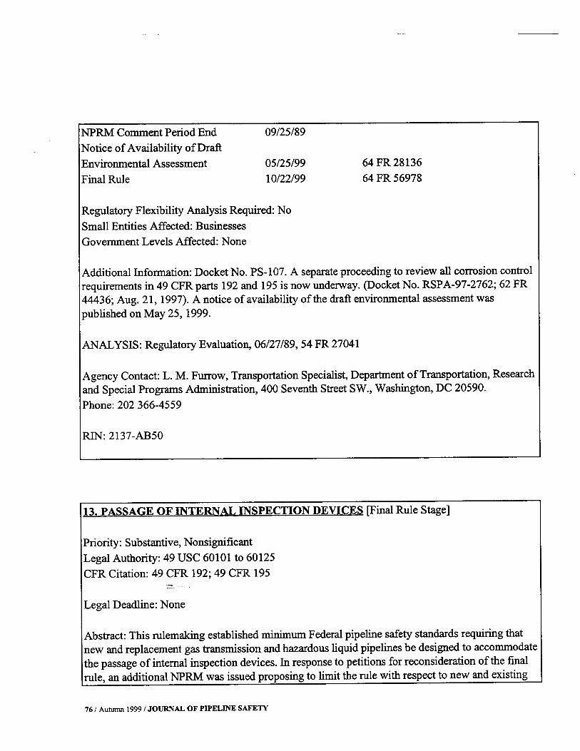
NPRM Comment Period End 09/25/89Notice of Availability of DraftEnvironmental Assessment 05/25/99 64 FR 28136Final Rule 10/22/99 64 FR 56978Regulatory Flexibility Analysis Required: NoSmall Entities Affected: BusinessesGovernment Levels Affected: NoneAdditional Information: Docket No. PS-107. A separate proceeding to review all corrosion controlrequirements in 49 CFR parts 192 and 195 is now underway. Docket No. RSPA-97-2762; 62 FR44436; Aug. 21, 1997. A notice of availability of the draft environmental assessment waspublished on May 25, 1999.ANALYSIS: Regulatory Evaluation, 06/27/89, 54 FR 27041Agency Contact: L. M. Furrow, Transportation Specialist, Department of Transportation, Researchand Special Programs Administration, 400 Seventh Street SW., Washington, DC 20590.Phone: 202 366-4559MN: 2137-AB5O13. PASSAGE OF INTERNAL INSPECTION DEVICES [Final Rule Stage]Priority: Substantive, NonsignificantLegal Authority: 49 USC 60101 to 60125CFR Citation: 49 CFR 192; 49 CFR 195Legal Deadline: NoneAbstract: This rulemaking established minimum Federal pipeline safety standards requiring thatnew and replacement gas transmission and hazardous liquid pipelines be designed to accommodatethe passage of internal inspection devices. In response to petitions for reconsideration of the finalrule, an additional NPRM was issued proposing to limit the rule with respect to new and existing76 / Autumn 1999 / JOURNAL OF PIPELINE SAFETY

offshore gas transmission lines and the replacement of onshore gas transmission lines in ruralareas.Timetable:Action Date FR CiteNPRM 11/20/92 57 FR 54745NPRM Comment Period End 01/19/93Final Rule 04/12/94 59 FR 17275NPRM 09/30/94 59FR49896NPRM Correction 10/19/94 59 FR 52863Limited suspension ofEnforcement 02/07/95 60 FR 7133Final Action 11/00/99Regulatory Flexibility Analysis Required: NoSmall Entities Affected: BusinessesGovernment Levels Affected: NoneAdditional Information: Docket No. PS-126. The integrity testing proposal in "Proposals forPipeline Safety," RIN 2137-AB27, was consolidated, in part, into this rulemaking.ANALYSIS: Regulatory Evaluation, 04/12/94, 59 FR 17275Agency Contact: R. Huriaux, Manager - Regulations, Department of Transportation, Research andSpecial Programs Administration, 400 Seventh Street SW., Washington, DC 20590.Phone: 202 366-4565Rll'T: 2137-AB71 JOURNAL OF PIPELINE SAFETY / Autumn 1999 / 77

14.+RESPONSE PLANS FOR ONSHORE OIL PIPELINES [Final Rule Stage]Priority: Other SignificantLegal Authority: 49 Usc 60101 to 60125CFR citation: 49 CFR 194Legal Deadline: Final, Statutory, August 18, 1992.Abstract: The interim final rule established regulations requiring response plans for certain onshoreoil pipelines. Those regulations are mandated by the Federal Water Pollution control Act asamended by the Oil Pollution Act of 1990 Pub. L. 101-380. Pipeline operators filed responseplans under this interim final rule, and numerous tabletop exercises and area exercises have beenconducted to validate the planning process. The purpose of these requirements is to improveresponse capabilities and minimize the impact of onshore oil spills from pipelines. This rule issignificant because of substantial public and congressional interest.The final rule will reflect theexperience gained under the interim final rule.Timetable:Action Date FR CiteInterim Final Rule 01/05/93 58 FR 244Comment Period End 02/19/93Notice of Public Meeting 06/15/94 59 FR 30755Notice of Public Hearing 11/29/96 61 FR 60679Correction 01/21/97 62 FR 2989Final Action 11/00/99Regulatory Flexibility Analysis Required: NoSmall Entities Affected: NoGovernment Levels Affected: NoneAdditional Information: Docket No. PS-130.ANALYSIS: Regulatory Evaluation, 0 1/05/93, 58 FR 244Agency Contact: James Taylor, Response Plans Officer, Department of Transportation, Research78/ Autumn 1999 / JOURNAL OF PIPELINE SAFETY

and Special Programs Administration, 400 Seventh Street SW., Washington, DC 20590.Phone: 202 366-8860RIN: 2137-AC3O15. ADOPTION OF INDUSTRY STANDARDS FOR LIOUEFIED NATURAL GASFACILITIES [Final Rule Stage]Priority: Substantive, NonsignificantLegal Authority: 49 USC 60101 to 60128CFR Citation: 49 CFR 193Legal Deadline: NoneAbstract: This action would replace most of the existing DOT standards governing the siting,design, and construction of liquefied natural gas facilities with an incorporation by reference of the1996 edition of the National Fire Protection Association document, ANSI/NFPA 59A,"Production, Storage, and Handling of Liquefied Natural Gas." The action, which is based on anNFPA rulemaking petition, is expected to reduce costs to the gas pipeline industry withoutcompromising safety.Timetable:Action Date FR CiteNPRM 12/22/98 63FR70735NPRM Comment Period End 03/23/99Final Rule 12/00/99Regulatory Flexibility Analysis Required: NoSmall Entities Affected: BusinessesGovermnent Levels Affected: NoneAdditional Information: Docket No. RSPA-97-3002. Notice of public JOURNAL OF PIPELINE SAFETY / Autumn 1999/ 79

meeting 63 FR 5918;2/5/98Agency Contact: Mike Israni, General Engineer, Department of Transportation, Research andSpecial Programs Administration, 400 Seventh Street SW., Washington, DC 20590.Phone: 202 366-4571Email: mike.israni~rpsa.dot.govRJN:2137-AD1116.+MAPS AND RECORDS OF PIPELINE LOCATIONS AND CHARACTERISTICS~NOTIFICATION OF STATE AGENCIES~ PIPE INVENTORY [Final Rule Stage]Priority: Other SignificantLegal Authority: 49 USC 60101 to 60125CFR Citation: 49 CFR 192; 49 CFR 195Legal Deadline: Final, Statutory, November 1, 1989.Abstract: This action proposes to equalize as far as possible the requirements that gas andhazardous liquid pipeline operators keep maps and records to show the location and othercharacteristics of pipelines. Operators would be required to keep an inventory of pipe andperiodically report mileage and other facts. In addition, operators would be required to providecertain information to State agencies upon request. This is a significant action because ofcongressional and State concerns about the need for appropriate public officials to have pipelineinformation.Timetable:Action Date FR CiteTerminate 09/00/00Regulatory Flexibility Analysis Required: No80/ Autumn 1999 / JOURNAL OF PIPELINE SAFETY

Small Entities Affected: BusinessesGovernment Levels Affected: NoneAdditional Infonnation: In furtherance of this rulemaking, the Department of Transportation'sOffice of Pipeline Safety OPS is working with other Federal and State agencies and pipelineindustry to create a national pipeline mapping system. This system, when complete, will show thelocation and selected attributes of the major natural gas and hazardous liquid pipelines andliquefied natural gas facilities operating in the United States. OPS will add additional data layersinto the system, including layers on population densities, unusually sensitive areas, natural disasterprobability and high consequence areas, hydrography, and transportation networks. OPS will usethe system to depict pipelines in relation to the public and the environment, and to work with othergovernment agencies and industry during an incident.A joint governmentlindustry Mapping Quality Action Team MQAT II has drafted nationalpipeline mapping standards that will be used to create the digital pipeline layer. These includestandards for electronic data submissions, paper map submissions, and metadata data on the data.The team has also drafted standards that will be used by the pipeline mapping repository receivingthe pipeline information. The team is currently pilot testing the draft standards and is working toestablish relationships with State agencies, industry, and others to exchange data that meets thestandards.Agency Contact: Christina Sames, Petroleum Engineer, Department of Transportation, Researchand Special Programs Administration, 400 Seventh Street SW., Washington, DC 20590.Phone: 202 366-4561RIN: 2l37-AB4817. UNDERWATER ABANDONED PIPELINE FACILITIES [Final Rule Stage]Priority: Substantive, NonsignificantLegal Authority: 49 USC 60101 to 60125CFR Citation: 49 CFR 192; 49 CFR 195Legal Deadline: Final, Statutory, April 24, 1994. JOURNAL OF PIPELINE SAFETY / Autumn 1999/ 81

Action Date FR CiteAbstract: This action will require operators of gas and hazardous liquid pipeline facilities to reportcertain information about abandoned underwater pipelines, including location, size, date ofabandonment, and compliance with applicable laws. The information will be available for use byother Federal agencies and state authorities.Timetable:NPRM 08/30/99 64 FR 47157Final Rule 03/00/00Regulatory Flexibility Analysis Required: UndeterminedSmall Entities Affected: BusinessesGovernment Levels Affected: UndeterminedAdditional Information: Docket No. RSPA-97-2094.Agency Contact: Melaine Barber, Transportation Specialist, Department of Transportation,Research and Special Programs Administration, 400 Seventh Street SW., Washington, DC 20590.Phone: 202 366-4595RIN: 2137-AC3318. ENFORCEMENT PROCEDURES [Final Rule Stage]Priority: Substantive, NonsignificantReinventing Government: This rulemaking is part of the Reinventing Government effort. It willrevise text in the CFR to reduce burden or duplication, or streamline requirements.Legal Authority: 49 USC 60101 to 60125CFR Citation: 49 CFR 190.209; 49 CFR 190.21382/ Autumn 1999/JOURNAL OF PIPELINE SAFETY

Legal Deadline: NoneAbstract: This action will revise RSPA's pipeline safety enforcement procedures to minimizepaperwork in uncontested cases where a person pays a proposed civil penalty or agrees to aproposed compliance order. The procedures will be changed to show that both responses areconsidered offenses in detennining any future civil penalty assessments. These changes willstreamline the enforcement process.Timetable:Action Date FR CiteNPR.M 08/12/99 64 FR 43972Comment Period Ends 10/12/99Final Rule 12/00/99Regulatoiy Flexibility Analysis Required: NoSmall Entities Affected: NoGovernment Levels Affected: NoneAdditional Information: Docket No. RSPA-98-4284. The changes to part 190 modify agency rulesof practice and procedure.Agency Contact: Linda Daugherty, Enforcement Officer, Department of Transportation, Researchand Special Programs Administration, 400 Seventh Street SW., Washington, DC 20590.Phone: 202 366-4577Email: daugherll~rspa.dot.govRIN: 2137-AD22 JOURNAL OF PIPELINE SAFETY / Autumn 1999 / 83

Long Term Action Stage19.+INCREASED INSPECTION REOUIREMENTS [Long-Term Actions]Priority: Other SignificantLegal Authority: 49 Usc 60101 to 60125CFR Citation: 49 CFR 192; 49 CFR 195Legal Deadline: Final, Statutory, October 24, 1995.Abstract: This rulemaking would address the need for additional periodic inspection of gas andhazardous liquid pipelines in high-density, environmentally sensitive, or navigable waterway areas.The regulations would prescribe circumstances under which such inspections must be conductedby internal inspection devices or equivalent means. This action is considered significant because ofsubstantial public interest.Timetable:Action Date FR CitePublic Workshop 10/18/95 60 FR 44821NPRM 06/00/00Regulatory Flexibility Analysis Required: NoSmall Entities Affected: BusinessesGovernment Levels Affected: NoneAdditional Information: Docket No. PS-141.Agency Contact: L. M. Furrow, Transportation Specialist, Department of Transportation, Researchand Special Programs Administration, 400 Seventh Street SW., Washington, DC 20590.Phone: 202 366-4559RrN: 2137-AC3884/ Autumn 1999/JOURNAL OF PIPELINE SAFETY

20. REGULATED GAS AND HAZARDOUS LIOUID GATHERING LINES [Long-TermActions]Priority; Substantive, NonsignificantLegal Authority: 49 Usc 60101 to 60125CFR Citation: 49 CFR 192; 49 CFR 195Legal Deadline: Final, Statutory, October 24, 1995.Abstract: This action would establish regulations for gas and hazardous liquid gathering lines inrural areas for which there are at present no safety regulations.Timetable: Next Action UndeterminedRegulatory Flexibility Analysis Required: NoSmall Entities Affected: BusinessesGovernment Levels Affected: UndeterminedAgency Contact: Richard Huriaux, Director, Technology & Regulations, Department ofTransportation, Research and Special Programs Administration, 400 Seventh Street SW.,Washington, DC 20590.Phone: 202 366-4565RIN: 2137-AC53 JOURNAL OF PIPELINE SAFETY / Autumn 1999 / 85