journal of pure and applied ultrasonics · 2012-02-03 · a publication of ultrasonics society of...
TRANSCRIPT

A Publication of Ultrasonics Society of IndiaA Publication of Ultrasonics Society of India
Journal of Pure and Applied
ISSN 0256-4637
Website : www.ultrasonicsindia.com
Ultrasonics
VOLUME 34 NUMBER 2-3 APRIL-SEPTEMBER 2012
Ultrasonics
OCIS E TS YCI ON FO IS NA DR IAT LU


27
Journal of Pure and Applied Ultrasonics
VOLUME 34 NUMBER 2 APRIL-JUNE 2012
CONTENTS
Message from the President. 29
Microstructural Characterization of Nuclear Materials by Ultrasonics 31
P. Palanichamy
Temperature dependent studies of thermodynamic properties of three binary systems using
experimentally determined values of density and ultrasonic velocity.
41
J.D. Pandey. K.K. Tiwari, Rupali Sethi, and Vinay Sanguri
Ultrasonic velocity and absorption study of binary mixtures of methanol with acrylonitrile by
interferometric method at different frequencies.
49
N.R. Pawar, O.P. Chimankar, V.D. Bhandakkar and N.N. Padole
Defect detection in plated structures using ultrasonic guided waves. 53
Sandeep K. Sharma, and Abhijit Mukherjee
Study of ultrasonic parameters of aqueous solutions of phloroglucinol. 60
D. Muraliji, and G. Karthikeyhan
Conference Report on National Seminar on Materials Characterization by Ultrasonics (NSMCU-2012). 64
Forthcoming Events 66
Website : www.ultrasonicsindia.com
A Publication of ― Ultrasonics Society of India

J. Pure Appl. Ultrason. 34 (2012) p. 28
Information for authors
1. Type of Contribution
JOURNAL OF PURE AND APPLIED
ULTRASONICS welcomes original research papers
and articles related to the subject of ultrasonics. The contributions may be
in the areas of physical ultrasonics,
medical ultrasonics, ultrasonic non-destructive evaluation including NDT, high power ultrasonics,
underwater acoustics, ultrasonic transducers,
transducer materials & devices
and any other related topic. These may fall into one of the following categories.
ResearchPapers - These should be on original
research work contributing to scientific developments. They should be written with a wide
readership in mind and should emphasize the
significance of the work.
Reviews Articles - Includes critical reviews and survey articles.
Research and Technical notes - These should be
short descriptions of new techniques, applications, instruments and components.
Letters to the editor - Letters will be published on
points arising out of published articles and papers and on questions of opinion.
Miscellaneous - Miscellaneous contributions such as
conference reports, Ph.D. thesis reviews and news
items are also accepted. Recommended lengths of contributions are: Research papers 2000-4000
words, reviews articles 2000-5000 words;
conference reports 500-1500 words; news items, research and technical notes up to 1000 words.
2. Manuscripts
Manuscripts should be typed on one side of the paper in double spacing with 25 mm margins on
all side of A4 size paper. A soft copy of the
manuscript in MS WORD for text and MS EXCEL for illustrations and a PDF file thereof may be sent
by e-mail or CD/DVD. Colour images should be
formatted as JPEG files. Figures submitted in colour would be publiashed in colour. Colour should be
avoided unless it is required in order to convey a
message or serve a purpose in the image.
Title - Titles should be short and indicate the nature
of the contribution. About 5 keywords may be given after the abstract.
Abstract - An abstract of 100-200 words should
be provided on the title page of paper and review article. This should describe the full scope of
the contribution and include the principal
conclusions.
Mathematics - Mathematical expressions should be
arranged to occupy the minimum number of lines
consistent with clarity e.g., (x2+y
2)/(x-y)
1/2
References - References should be indicated in the text by its number only. The reference number
should be given as superscript. The corresponding
reference shall contain the following information in order; names and initials of author(s)in bold, full
title of the work, journal or book title in italic,
volume number in bold, the year of publication in brackets and the page number. As example: Vasanth
B.K., Palanichamy P., Jayakumar T. and Sankar
B.N., Assessment of residual stresses in a carbon
steel weld pad using critically refracted longitudinal (LCR) waves, J. Pure Appl. Ultrason., 28 (2006) 66-
72.
Units and Abbreviations - Authors should use SI units wherever possible.
3. Reprints
One copy of the issue in which the paper is
published is sent to the author free of charges.

29
Message from the President, USI
I feel honoured for being elected to the august position of the President of the Ultrasonics Society of India (USI). I would like to take this opportunity
to welcome the members of the newly elected Executive Council of the USI.
Together with your cooperation, we will try to raise the USI to greater heights in days to come.
‘Ultrasonics’ today is a very powerful branch of science and
technology which is constantly gaining in its relevance to the Society. The ultrasound has penetrated in many spheres of societal importance such as
medical practice, nondestructive testing and process engineering in industry,
remote sensing and actuation, bio-medical and nano-technology research, ocean technology, etc. It is difficult to enumerate all the applications where
ultrasonics has made its impact. Many more applications are foreseen in future
specially in medicine, industrial processing, NEMs and MEMs sensors and actuators, robotics, novel piezoelectric materials, etc. where considerable
amount of innovative research is taking place all around the world.
Technological developments based on ultrasonic principles have happened in
India in last decades including non-destructive testing, ultrasonic processing (machining/cleaning/welding etc.), ocean research, medicine, etc. I look
forward to rapid growth in research and development activities in research
institutions, in partnership with industry, under the auspices of the Ultrasonics Society of India. The Society can further contribute in a significant way to
the promotion of teaching in ultrasonics and related areas at the university
level. A good number of experiments based on ultrasonics/ electro-acoustics as
a part of the practical training to the graduate students of physics can be introduced in which the Ultrasonics Society can play an important role.
It is heartening to note that the Journal of Pure and Applied Ultrasonics (JPAU) is being published in its 34
th volume in 2012. The JPAU has been
serving well the ultrasonics fraternity in the country by disseminating the
research output from the universities, research institutes, industries, etc. in ultrasonics and related areas. JPAU has been publishing, besides research
articles, features like profiles/ obituaries of eminent personalities associated
with ultrasonics, new books, calendar of forthcoming events, new members,
etc. from time to time. The USI has instituted Dr S Parthasarathy Memorial Award for the best paper published in JPAU in a year.
The journal has before it future challenges to improve its impact factor. These include making publication of the journal more punctual, online and
e-publishing, abstracting in international science/ engineering abstracts, SCI
status of the journal, etc.

30
I look forward to greater indulgence from the readers and members of
USI to the cause of the journal by contributing their best research outputs to take
the country forward in the ultrasonic technology, which can potentially enable the Indian industry to become more competitive in ultrasonic products and
applications.
(Vikram Kumar)

J. Pure Appl. Ultrason. 34 (2012) pp. 31-40
Microstructural Characterisation of Nuclear Materials by Ultrasonics
P. Palanichamy
Nondestructive Evaluation Division, Metallurgy and Materials Group
Indira Gandhi Centre for Atomic Research, Kalpakkam – 603 102, INDIA
Email: [email protected]
Over last two decades, significant progress has been made on the characterisation of microstructures and material
properties using ultrasonic attenuation and velocity measurement methods. Ultrasonic characterisation of microstructural feature
in nuclear structural materials is a challenging and a very useful task to the industries. In this paper, some of the important
developmental works carried out on characterisation of microstructures in a variety of nuclear structural materials such as AISI
type 316 austenitic stainless steels, modified alloy D9, and Zircaloy-2 are presented. Potential of high frequency (>20MHz)
ultrasonic measurements for characterisation of precipitation that have a bearing in the properties and performance of the
materials in service has also been highlighted. Paper also discusses the use of very high frequencies in the GHz range through
scanning acoustic microscopy for the characterisation of sensitized microstructures in AISI type 304 LN stainless steel.
Keywords: Ultrasonics, attenuation, velocity, microstructural characterisation, nuclear structural materials, high frequency,
scanning acoustic microscopy, sensitisation
Introduction
Advancement in Non-Destructive Evaluation
(NDE) techniques is possible with the advent of
advanced electronics, innovations in sensor
technology, improvement in the methodologies, etc.
The outcome of the developments in NDE techniques
is the improvement in fitness for purpose of fabricated
components and their performance in service with
possibility for their life extension. These advantages
are being passed on to the industries on a regular
basis. In this context, Indira Gandhi Centre for
Atomic Research (IGCAR) is the pioneer and
continues to play a major role in developing and
transferring the advances in the NDE techniques not
only to the nuclear industry but also to other strategic
and core sectors such as space, defence, chemical and
power. Among popular NDE techniques, the
ultrasonic technique is applied rather extensively for a
variety of problems related to microstructural
characterisation, texture evaluation and residual stress
measurements1-10
. IGCAR has taken up
comprehensive programme well in advance (almost
two decades now) on the development of advanced
NDE techniques to cater to the growing needs. It is
well known that material microstructure and
mechanical strength are inter-related. Correlations
have been established between yield strength, grain
size and ultrasonic attenuation1. Basic ultrasonic
measurements viz. attenuation and velocity have been
used for determination of grain size2-6
, ultrasonic
longitudinal and shear wave velocity measurements
have been used to obtain degree of recrystallisation7,
measurement of texture8 and residual stresses
9-10.
Studies were made to evaluate microstructures
through ultrasonic attenuation and the estimation of
fracture toughness using the measured ultrasonic
parameters11-12
. Detailed study on the influence of
microstructure on ultrasonic velocity was carried out
in Nimonic alloy PE-1613
. Ultrasonic velocity
measurements are useful in revealing the copper
precipitation in 17-4-PH steel14
. Ultrasonic velocity
measurements have been correlated with the
precipitation behaviour and yield strength in service
exposed and heat-treated Ni based superalloy Inconel
62515
. The study revealed that different precipitates,
such as Ni2 (Cr,Mo), γ'', δ and grain boundary
carbides, affect the yield stress and ultrasonic velocity
differently and hence the type of the precipitate plays
an important role in the correlation of these two
parameters in Inconel 62515
. Ultrasonic NDE of
microstructures are also being considered to enable
in-situ component monitoring for both pre-service
quality and in-service performances. It is noted that
ultrasonic techniques and methodologies are far
superior as compared to other major NDE techniques
for nondestructive evaluation of microstructures
especially in nuclear structural components16-18
.
In this paper, some of the important developmental
works carried out at the authors’ laboratory in
characterisation of microstructures in a variety of
_______________
*Life fellow, Untrasonic Society of India
Presented at National Seminar on Materials Characterization by
Ultrasonic (NSMCU-2012), 3-4 April-2012, Amity School of
Engineering and Technology, Bijwasan, New Delhi.

J. PURE APPL. ULTRASON., VOL. 34, NO. 2 (2012)
32
nuclear structural materials such as AISI type 316
austenitic stainless steels, modified alloy D9 and
Zircaloy-2 will be presented. Potential use of high
frequency (>20MHz) ultrasonic measurements for
characterisation of precipitation that has a bearing on
the properties and performance of the materials in
service has also been highlighted. Ultrasonic
measurements have also been correlated with the
precipitation behaviour and toughness changes in
service exposed and rejunivated Ni based superalloy
Inconel 625. This paper brings out the details of the
microstructural studies carried out in nuclear materials
by using precise ultrasonic attenuation and velocity
measurements in the frequency range 2-100 MHz. It
also discusses the use of very high frequencies through
SAM system for the characterisation of sensitized
microstructures in AISI type 316 stainless steel.
Grain size measurement in AISI type 316 stainless
steel
Austenitic stainless steels are used as structural
materials in nuclear, chemical and petrochemical
industries. The knowledge of average grain size of
these steels is important to ensure optimum
mechanical properties. Over the years, we have
gained experience in developing various ultrasonic
methods for the estimation of grain size in austenitic
stainless steels. Brief details on the relative merits of
the developed ultrasonic methods are also given. AISI
type 316 stainless steel specimens having dimensions
50mm diameter and 50mm thickness were heat
treated at different temperatures (1323K to 1473K)
for different time durations (15 min to 2 hr). The
average grain size in these specimens is measured
metallographically as per the procedure given in the
ASTM standard E112 is in the range of 30 -170 µm.
Fig. 1 shows the photomicrographs of three different
specimens. Following are the ultrasonic parameters
used in different methods: (i) attenuation coefficient3,
(iii) first back wall echo amplitude4, (iii) velocity
5,
and (iv) back scattered leaky Rayleigh wave
amplitude6. Primary steps involved in the grain size
estimation in all these methods are: (i) specimen
preparation, (ii) measurement of ultrasonic parameter,
(iii) metallographic examination of specimens, (iv)
generation of calibration graph between the ultrasonic
parameter and the metallographically estimated grain
size, and (v) estimation of grain size in new
specimens to validate the calibration graph and also to
establish the accuracy.
Comparison of attenuation measurements made at
different frequencies showed that measurements made
at 4MHz longitudinal wave transducer gave better
results for the grain size estimation. Problems
connected with the attenuation method such as
couplant and diffraction corrections are eliminated in
another method that depends on Ultrasonic Relative
Attenuation (URA). Measurements with a 10MHz
immersion transducer gave the best result. This is a
first of its kind approach. Ultrasonic velocity
measurements were used for the first time for the grain
size estimation. Accurate velocity measurements at
2MHz were also made for longitudinal and shear
waves using pulse-echo-overlap technique. A linear
Fig. 1—Metallographic photomicrographs of three different specimens of AISI type 316 stainless steel. (a) Fine, (b) Medium and
(c) Coarse grain sizes.

PALANICHAMY: MICROSTRUCTURAL CHARACTERISATION OF NUCLEAR MATERIALS
33
relationship was found to exist between the velocity
and the metallographically estimated grain size. Unlike
the attenuation and first back wall echo amplitude
methods, velocity measurements are also found to be
less affected by changes in the grain size distribution.
For the estimation of only surface/subsurface grain
size, a method based on the measurement of the
amplitudes of the back scattered Leaky Rayleigh
Waves (LRW) was developed.
Results indicated that confidence level of 75% only
could be achieved using conventional attenuation
method and the repeatability of the measurement data
was also found to be inadequate. Measurements using
first back wall echoes and LRW amplitudes gave better
than 80% confidence level. It was found that best
confidence level of 85% in the grain size estimation
was achieved using velocity measurements. As
compared to the longitudinal waves, shear waves were
found to be more sensitive in grain size estimation
using the velocity measurements. Selection of proper
frequency also plays an important role in grain size
estimation by different methods. These studies show
that: (i) Ultrasonic methods can replace time
consuming metallographic methods for grain size
estimation. (ii) URA method is most useful for coarse
grained and thick stainless steels. The method is also
amenable for continuous measurements in production
line. However, specimen thickness variations should be
within 100 µm. (iii) Method based on velocity
measurements is best for achieving higher accuracy
level in grain size measurements. This is also less
influenced by variation in grain size distribution.
Recently, method based on spectral approach (shift in
the peak frequency due to grain size variation) has also
been proposed and advantage of this method in average
grain size determination is that variation in couplant
thickness does not affect the results19
. Qualitative
performance of various ultrasonic based methods in
comparison to metallographic method is given in Table 1.
Precipitation studies in nuclear grade AISI type 316
LN stainless steel
Nitrogen alloyed austenitic stainless steels have
emerged as candidate materials for a variety of
engineering applications by virtue of their superior
mechanical and chemical properties as compared to
other austenitic stainless steel grades such as 304L,
304 and 316. The vastly improved properties of
nitrogen alloyed steels result from the higher binding
energies of nitrogen with chromium and greater
pinning effects of dislocations, compared to carbon
steels. Addition of nitrogen leads to stronger influence
of the thermo-mechanical history and the
microstructures on the material properties, since the
thermo-mechanical history controls the nitrogen
distribution in the steel. In order to ensure desired
mictrostructural state, basic understanding on the
nitrogen role in the various aspects of microstructural
parameters and mechanical properties is very
essential. In addition to optical and electron
microscopy, ultrasonic measurements have been
carried out to correlate the microstructural features
with ultrasonic parameters. The various stages of
repartitioning of nitrogen and precipitation of nitrides
in nuclear grade 316LN stainless steel on ageing at
1123K have been characterized using transmission
electron microscopy (TEM). The formation of Cr-N
clusters on aging for 10h, followed by intra granular
precipitation of coherent Cr2N beyond 25h and finally
the cellular precipitation of Cr2N and formation of chi
phase beyond 500h have been well characterized and
reported20-22
. Here correlation of these microstructural
changes with ultrasonic velocity measurements has
been presented.
Fig. 2 shows the variation in ultrasonic velocity
with ageing treatment for longitudinal wave
frequencies 10, 25, 50 and 75 MHz. It is seen that
ultrasonic velocity increases up to 25h with ageing.
On further ageing at the same temperature till 2000h,
Table 1—Comparison of performance of ultrasonic based and metallographic methods on the determination of average grain size in
austenitic stainless steel type 316.
METHOD
PROPERTY UA UB URA LRW UV Metallography
Volume Analysis YES NO YES NO YES Possible
Standard Offing Lab. Lab. Lab. Lab. YES
Confidence Level 70% 75% 80% 80% 85% Standard
Instruments Less Costly Costly Less Costly Mod. Mod. Costly
Coarse Grain Poor Poor Best Best Good Better
Thicker Specimens Poor Best Best Better Better Only Surface Analysis
On-line Measurements Fair Fair Best Poor Better Not Possible
Note: UA-Ultrasonic attenuation method; UB-Ultrasonic back scattering; URA-Ultrasonic relative attenuation; LRW-Leaky Rayleigh
wave; UV-Ultrasonic velocity; RSW-Rayleigh surface waves.

J. PURE APPL. ULTRASON., VOL. 34, NO. 2 (2012)
34
the velocity decreases. No difference in the trends was
observed between the velocities and the ageing time,
at the four frequencies studied. The increase in the
velocity during 10h of ageing (Stage-A) is mainly
associated with matrix effects. Formation of Cr-N rich
clusters after 10h of ageing leaves behind a relatively
nitrogen depleted and consequently strain free matrix.
Formation of coherent intragranular Cr2N precipitates
on ageing up to 25h is also associated with a small
increase in velocity (Stage-B). This can be attributed
mainly due to modulus effects, arising from the large
elastic modulii difference between the matrix and the
precipitate. Similar observations of increase in
ultrasonic velocity during the initial stages of
precipitation as a result of modules effect have been
observed during copper precipitation in 17-4 PH
steels14
. Formation of cellular precipitates beyond
500h and coarse chi phases beyond 1000h result in
increased scattering at the precipitate/matrix interface
boundaries and thereby decrease the ultrasonic
velocity (Stage-C). A larger decrease in velocity with
increasing frequency of ultrasonic waves in Stage-C,
can be seen from Fig. 1. This is because, as the
ultrasonic frequency is increased from 5 MHz to 50
MHz, the wavelength decreases by about 10 times.
The half wavelength of 50 MHz ultrasonic waves
being about 58 µm is almost equivalent to the
austenite grain size. Since the cellular precipitates
extend over the entire grain, a 50 MHz wave would
have greater probability of interacting with these
precipitates and consequently would undergo greater
scattering in comparison to 5 or 10 MHz wave.
Consequently the significant difference between the
velocities of the waves with different frequencies,
particularly beyond 500h of ageing as seen from
Fig. 1 can be understood well. TEM studies carried
out earlier on evolution of microstructural features in
these steels correlate well with the ultrasonic
measurements20-22
. The analysis of the present work
suggests that ultrasonic evaluation may be a handy
tool to study the precipitation reaction involving
interstitial elements like nitrogen, and also those
associated with large changes in the lattice strains.
Annealing behaviour of cold worked alloy D9
7
Recovery, recrystallisation and grain growth are
the three stages of an annealing processes, which
bring out the changes in the cold worked
microstructure. Among these processes,
recrystallisation is the microstructural process by
which new strain free grains form from the deformed
microstructure. Depending on the material, the
recrystallisation process is often accompanied by
other microstructural changes like decomposition of
solid solution, precipitation of second phases, phase
transformations etc. in addition to recovery and strain
free grain formation. These changes influence the
kinetics of recrystallisation and often mask the picture
revealed by certain methods of analysis. The most
common techniques used to study annealing
behaviour of metals and alloys are the hardness
testing, optical and electron microscopy. The
techniques of hardness measurement and optical
metallography often found to give different values for
the temperature or the time at which the
recrystallisation process either starts or is completed.
Quantitative metallography techniques, which are
often used to measure the extent of the
recrystallisation process, are time consuming and
error prone. In this work, ultrasonic velocity
measurement technique has been used to characterize
the progress of recrystallisation.
Ultrasonic velocity measurements using 4MHz
shear and longitudinal waves were carried out in 20%
cold worked (tensile pulled) and annealed specimens
of 15Cr-15Ni-2.2Mo-Ti modified austenitic stainless
steel (alloy D9) to characterize the isothermal and
isochronal annealing behaviour. Fig. 3 shows the
variation in longitudinal velocity with annealing time.
VL1 is the velocity along the tensile pulling direction
and VL2 is the velocity perpendicular to the tensile
pulling direction. The velocity exhibits a slight
increase in the recovery region followed by a sharp
and continuous decrease in the recrystallisation region
and reaches saturation on completion of
recrystallisation (Fig. 3). Increase in the velocity in
the recovery region is due to the reduction in the
distortion of the lattice in comparison to the cold
worked condition. The sharp decrease in the velocity
Fig. 2—Ultrasonic velocity as function of ageing time in AISI
type 316LN stainless steel. ‘A’ refers to frequency independent
modulus-dependent velocity change, ‘B’ refers to frequency
dependent and ‘C’ refers to scattering induced velocity change.

PALANICHAMY: MICROSTRUCTURAL CHARACTERISATION OF NUCLEAR MATERIALS
35
during recrystallisation is attributed to the change in
the texture. Further annealing treatment shows
saturation in velocity. Thus velocity is found to be
sensitive to the different microstructural changes
taking place during recovery, recrystallisation and
saturation. Fig. 4 show the variation of three velocity
ratio parameters, which are combination of the shear
wave velocities, and the fraction unrecrystallised
microstructure as a function of annealing time at
1073K. In the velocity ratio parameters, VS1 is the
shear wave velocity measured parallel to the tensile
pulling direction, VS2 is the shear wave velocity
measured perpendicular to tensile pulling direction
but polarisation parallel to pulling direction and VS3
is the velocity perpendicular to tensile pulling
direction with wave polarisation perpendicular to
tensile pulling direction.
The velocity parameter, measured in the transverse
direction with polarization directions parallel and
perpendicular to the cold worked direction is found to
closely represent the extent of progress of
recrystallisation (Fig. 5), as measured by optical
metallography. It has also been verified that velocity
measurements could sense the onset, progress and
completion of recrystallisation more accurately
compared to that of hardness and strength
measurements (Figs. 6 & 7). Using the velocity ratio
parameters, there is no necessity for thickness
measurement and hence the difficulties associated
with specimen thickness measurements are avoided.
Fig. 3—Variation of ultrasonic velocity with annealing time at 1073K in 20% cold worked Alloy D9.
Fig. 4—Variation of velocity ratio parameter and the fraction unrecrystallised microstructure as a function of annealing time at 1073K in Alloy D9.

J. PURE APPL. ULTRASON., VOL. 34, NO. 2 (2012)
36
Fig. 6 shows the variation in velocity ratio parameter
with fraction of recrystallised microstructure. This
would be useful approach for on-line monitoring of
microstructures in the production environment using
velocity ratio parameters. In the case of manufactured
components under service conditions, these
parameters would be again useful for continuously
monitoring to identify any change in the original
microstructural state of the material without affected
by any local variation in the material thickness.
Assesment of hard intermetallic phases in zircaloy-2 Zirconium alloys are important materials for core
components of pressurised heavy water reactors. Among
various zirconium alloys, Zircaloy-2 is used for
fabrication of fuel cladding tubes, calandria tubes and
pressure tubes of these reactors. One of the steps in
fabrication of Zircaloy-2 components is the β-quenching
of the hot extruded billets. β-quenching treatment is
given to Zircaloy-2 to homogenize the chemical
composition and randomize the texture. Improper
β-quenching treatment results in the precipitation of
Fig. 6—Variation of hardness and ultrasonic velocity as function
of annealing time.
Fig. 7—Variation of yield strength and ultrasonic velocity as
function of annealing time.
Fig. 5—Variation of velocity ratio parameter with extent of recrystallisation.

PALANICHAMY: MICROSTRUCTURAL CHARACTERISATION OF NUCLEAR MATERIALS
37
hard intermetallics and α-phase and thus interferes
with further forming operations thus leading to
rejection of the final fabricated products.
Ultrasonic velocity measurements carried out in the
frequency range 2 to 25 MHz showed a decreasing
trend with ageing temperature up to 773K and further
increase in ageing temperature indicated increase in the
ultrasonic velocity (Fig. 8)23
. Hardness measurements
indicated an opposite trend to the velocity
measurements i.e. an increasing trend up to the ageing
temperature of 773K and beyond this temperature, a
decrease in the hardness was observed (Fig. 8). The
higher hardness in the intermediate temperature range
is attributed to precipitation of hard intermetallics23
.
Ultrasonic velocity measurements at 50 and 100
MHz frequencies indicated that at 50 MHz, decreasing
trend in velocity was observed up to 873K and further
ageing showed increase in velocity
(Fig. 9)23
. This is similar to that observed at lower
frequencies, except for the extent of variation.
However at 100 MHz frequencies, measurements
showed a continuous decrease in the velocity with
ageing temperature. This continuous decrease in the
velocity at higher frequencies in specimens aged at
higher temperatures has been attributed to the changed
microstructure i.e. dissociation of β-quenched
martensite and formation of small size and isolated
α-phase at higher temperatures. At lower frequencies,
absence of continuous decrease in velocity beyond
873K is attributed to long wavelength of the ultrasonic
waves and hence lack of appreciable interaction
between ultrasonic waves and the small size and
isolated α -phase. These studies demonstrate that while
the low frequency velocity measurements are capable
of revealing the presence of hard intermetallics, high
frequency velocity measurements are useful for
revealing the early stage dissociation of β-quenched
microstructure to α-phase.
Ultrasonic attenuation measurements were also
carried out at low frequencies (2 and 10MHz) and at
higher frequencies (25, 50 and 100 MHz), respectively
in specimens at different ageing temperatures23
. The
change in the attenuation due to ageing is marginal at 2
MHz. At all other frequencies, variation in the
attenuation with ageing temperature generally shows
an opposite trend to that of the velocity i.e. an
increasing trend in the attenuation with ageing
temperature and reaches a peak at 873K and beyond
that, attenuation decreases at further ageing
temperature (973K). The scatter-band for low
frequency attenuation measurements is high, i.e. 0.04
dB/mm even in the case of immersion type
measurements and hence low frequency attenuation
measurements can’t be employed reliably for
characterization of different microstructures in the β-
quenched and aged specimens. However, the scatter
band in the attenuation measurements at higher
frequencies (25, 50 and 100 MHz) is relatively less, i.e.
0.005 dB/mm and the observed trend can reliably be
taken into account for interpreting the results with
respect to the changes in the microstructure. The
increasing trend in the attenuation up to 873K is
attributed to precipitation of hard intermetallics.
Fig. 8—Ultrasonic velocity and hardness as a function of ageing
temperature β-quenched Zircaloy-2.
Fig. 9—Variation of ultrasonic velocity with ageing temperature
for 25, 50 and 100 MHz ultrasonic frequencies in β-quenched
Zircaloy-2.

J. PURE APPL. ULTRASON., VOL. 34, NO. 2 (2012)
38
Subsequent reduction in the attenuation at 973K is
attributed to reduced amount of precipitation of
intermetallics at higher temperatures. The reduction in
the attenuation occurs in spite of precipitation of a
small amount of α-Zr.
Application of Scanning Acoustic Microscope (SAM)
for the characterisation of sensitized microstructures
in AISI type 304 stainless steel
Scanning Acoustic Microscope (SAM) uses focused
high frequency ultrasound to image and characterise
the structural details of materials. It is used for
microstructural characterisation, failure analysis,
estimation of fracture toughness of ceramics and
nondestructive evaluation. It has potential applications
for elastic property characterisation, internal stress
measurements and biological applications. A
sophisticated SAM system has been procured first time
in India, from M/s. KSI Germany during March 2007
and installed successfully at NDED. The operating
frequency range of the system is 673–1023 MHz which
corresponds to a spatial resolution of 1 µm. In a
systematic study undertaken using SAM, surface and
subsurface high resolution acoustic images of heat
treated and sensitized AISI type 304 LN stainless steel
and granites have been obtained and correlated.
Sensitisation, in the strict sense, means ‘sensitivity,
of a material to Inter Granular Corrosion (IGC). The
phenomenon of sensitization is of great practical
significance because of thermal exposures during
welding, fabrication, heat treatment etc. produce the
metallurgical condition susceptible to intergranular
attack. Austenitic stainless steel, such as AISI type 304
LN is candidate material for fast breeder reactor
applications. This steel is used as fuel pin material under
the 20% cold worked condition. However, the material
gets sensitized when it is slowly cooled through the
temperature range 450–850 °C or isothermally treated in
the above range. Sensitization brings down the
mechanical, creep and corrosion properties of the
components made out of this steel. Hence systematic
studies mainly using metallographic techniques are
usually followed for monitoring sensitization. However,
metallographic techniques are time consuming and
destructive. Moreover, metallographic techniques do not
provide depth information. Hence SAM studies have
been undertaken for the evaluation sensitized properties
of AISI type 304 LN.
Figure 10(a) shows the optical image of the polished
surface of the not sensitized sample. Figure 10(b)
shows the SAM image obtained by raster scanning at
850 MHz mid frequency and figure 10(c) represents
the optical image of the etched AISI 304 LN not
sensitized sample. Fig. 11(a) shows the optical image
of the polished sensitized sample. Fig. 11(b) shows the
Fig. 10—Images of the only polished 304LN sample
Fig. 11—Images of the polished and sensitized 304 LN sample.

PALANICHAMY: MICROSTRUCTURAL CHARACTERISATION OF NUCLEAR MATERIALS
39
SAM image obtained by raster scanning at 850 MHz
mid frequency of the sensitized sample. Figure 11(c)
represents the optical image of the etched AISI 304 LN
sensitized sample about the temperature 700°C for 100
hrs. The SAM images reveal the broadening of the
grain boundaries in sensitized sample, which is due to
the formation of the chromium carbide precipitation
along the grain boundaries.
Sensitization brings down the mechanical, creep
and corrosion properties of the components made out
of this steel. Hence systematic studies mainly using
metallographic techniques are usually followed for
monitoring sensitization. However, metallographic
techniques are time consuming and destructive.
Moreover, metallographic techniques do not provide
depth information. Hence SAM studies have been
undertaken for the evaluation sensitized properties of
AISI type 304 LN.
Fig. (12) show the sub-surface SAM images
obtained for the same mid band frequency 850 MHz
but having the defocusing at Z = 10.3µm. The grain
boundaries are distinctly different due to the effect of
sensitization. In the sensitized microstructure
broadening of the grain boundaries take place due to
the effect of stress relaxation by the depletion of
chromium to the gain boundaries and the formation of
chromium carbides at the boundaries. The strain
created at the grain boundaries are seen as fringes.
Summary
An overview on the usefulness of ultrasonic velocity
and attenuation measurements for characterisation of
microstructures in austenitic stainless steels and
Zicalloy-2 has been given. Various ultrasonic
parameters based on wave decay and wave speed have
been established for the quantitative determination of
average grain size in AISI type 316 austenitic stainless
steel. Studies made in nuclear grade 316LN stainless
steel reveals that ultrasonic evaluation may be a handy
tool to study the precipitation reaction involving
interstitial elements like nitrogen that are associated
with large changes in the lattice strains. Ultrasonic
velocity measurements made in the annealed
specimens of 20 % cold worked alloy D9 can sense
onset, progress and completion of recrystallisation
more accurately as compared to that of hardness and
strength measurements. Ultrasonic velocity
measurements performed in β-quenched and aged
Zircaloy-2 specimens reveal the capability of velocity
measurement technique in detecting the presence of
hard intermetallics. SAM studies carried out on only
polished and sensitized AISI type 304 LN specimens
reveals that grain boundaries are more distinct from
optical and chemically microstructures. In addition, in
the sensitized specimen strain created at the grain
boundaries are seen as fringes.
Acknowledgement
I am thankful to Dr. T. Jayakumar, DMMG,
Dr. B.P.C. Rao, Head, NDED, Dr. A. Joseph, Head,
ISI & RSM Section and Dr. M. Vasudevan,
Programme Leader, MMG for their prolonged help
and many useful discussions during the course of the
studies.
References 1 R. Klinman and E.T. Stephenson, “Ultrasonic prediction of
grain size and mechanical properties in carbon steel”, Mat.
Eval. Vol. 39, 1981, pp. 1116-1120.
2 E.P. Papadakis, “Physical acoustics and microstructure of
iron”, International Metals Rev., Vol. 1, 1984, pp. 1-24.
3 P. Palanichamy, C.V. Subramanian, P. Barat, D.K.
Bhattacharya and Baldev Raj, "A NDT method for grain size
determination in austenitic stainless steel", Trans. IIM, Vol.
41(5), Oct.1988, pp. 485-488.
4 P. Palanichamy, A. Joseph and T. Jayakumar, "Grain size
measurements in austenitic stainless steel using ultrasonics",
Insight, Vol. 36(11), November 1994, pp. 874-877.
Fig. 12—SAM Image defocused (sub-surface) at Z= 10.3µm of the only polished and sensitized AISI 304LN

J. PURE APPL. ULTRASON., VOL. 34, NO. 2 (2012)
40
5 P. Palanichamy, A. Joseph, T. Jayakumar and Baldev Raj,
"Ultrasonic velocity measurements for estimation of grain
size in austenitic stainless steel", NDT & E International.
Vol. 28 (3), 1995, pp. 179-185.
6 P. Palanichamy and T. Jayakumar, “Grain size measurements
by ultrasonic Rayleigh surface waves”, 14th WCNDT, New
Delhi, Dec. 8-13, 196, pp. 2253-2256.
7 P. Palanichamy, M. Vasudevan, T. Jayakumar, S. Venugopal
and Baldev Raj, “Ultrasonic velocity measurements for
characterizing the annealing behaviour of cold worked
austenitic stainless steel", NDT&E International, Vol. 33,
2000, pp. 253-259.
8 P. Palanichamy and M. Vasudevan, “Characterisation of
annealing behaviour and evaluation of texture coefficients in
titanium modified 20% cold worked 316 type austenitic
stainless steel using ultrasonics”, Materials Evaluation,
31(9), Sept. 2003, pp. 1020-1025.
9 M. Pies, Non-Destructive Determination of Materials
Texture by Ultrasonics, MS Thesis, University of Houston,
Texas, USA; Diploma Thesis, University of Saarlandes,
Saarbruecken, FRG, 1989.
10 P. Palanichamy, A. Joseph, D.K. Bhattacharya and Baldev
Raj, “Residual stresses and their evaluation in wleds” in
Welding Engineering Handbook, Vol. 1, eds. S. Sundarrajan,
S.Vijaya Baskar and G.C. Amarnath Kumar (Radiant
Publications Pvt. Ltd., Secundrabad, 1992), pp. 269-296.
11 A.N. Sinclair and H. Eng, “Ultrasonic determination of
fracture toughness” in “Nondestructive Characterisation of
Materials – II”, Editors J.F. Bussiere, J.P. Monchalin, C.O.
Ruud and R.E. Green Jr., Plenum Press (New York), 1987,
pp. 251-259.
12 G. Canella and M. Taddei, “Correlation between ultrasonic
attenuation and fracture toughness of steels” in
“Nondestructive Characterisation of Materials – II”, Editors
J.F. Bussiere, J.P. Monchalin, C.O. Ruud and R.E. Green Jr.,
Plenum Press (New York), 1987, pp. 261-269.
13 T. Jayakumar, Baldev Raj, H. Willems, and W. Arnold,
“Influence of microstructure on ultrasonic velocity in
Nimonic alloy PE16” Review of Progress in Quantitative,
NDE, Plenum Press, New York., 10b, 1991, pp.1693-1700.
14 D.K. Bhattacharya, T. Jayakumar, P. Palanichamy and
Baldev Raj, "Ultrasonic velocity and elastic modulus
measurements for microstructural characterization of heat
treated 17-4-PH stainless steel", Proc. 7th Asia Pacific
Conf.on NDT, Shanghai, China, Sept. 1993, pp. 110-114.
15 Anish Kumar, Vani Shankar, T. Jayakumar, K. Bhanu
Sankara Rao and Baldev Raj, “Effect of precipitates on the
correlation of ultrasonic velocity with mechanical properties
in ni-based superalloy inconel 625”, Proceeding of the 8th
ECNDT, Barcelona, June 2002
16 Baldev Raj, P. Palanichamy, T.Jayakumar, Anish Kumar, M.
Vasudevan and P. Shankar “Characterization of
microstructures in austenitic stainless steels by ultrasonics”,
Proc. of Rev. Progress in Quantitative NDE, Montreal,
Canada, 25-30th July 199, Eds. D.O. Thompson and D.E.
Chimenti, Melville, New York 2000, pp. 1425-1431.
17 Anish Kumar, T. Jayakumar, Baldev Raj and K. K. Ray,
"Characterization of the Metallurgical Condition of Titanium
Alloy by Ultrasonic Measurements", Insight, Vol. 45 (7),
2003, pp. 484-487.
18 Baldev Raj, P. Palanichamy and T. Jayakumar, “Science and
technology of non-destructive testing and evaluation and
characterisation”, Insight, Vol. 45(1), January 2003,
pp 15–30.
19 Anish Kumar, T. Jayakumar, P. Palanichamy and Baldev
Raj, "Effect of grain size on ultrasonic spectral parameters in
AISI type 316 stainless steel", Scripta Materialia, Vol. 40(3),
1999, pp. 333-340.
20 P. Shankar, P. Palanichamy, T. Jayakumar and Baldev Raj,
“Influence of nitrogen repartitioning on microstructure and
elastic constants in thermally aged nuclear grade 316LN
austenitic stainless steels” – Met. Mater. Trans. 32 A, 2001,
pp. 2959-2968.
21 D. Sundararaman, P. Shankar and S. Ranganathan, Metall.
Trans., “Electron microscopic study of Cr2N formation in
thermally aged 316LN austenitic stainless steel”, 27A, 1996,
pp. 1175-1186.
22 P. Shankar, D. Sundararaman and S. Ranganathan,
“Clustering and ordering of nitrogen in nuclear grade 316LN
austenitic stainless steel “, J. of Nucl. Mater., 254, 1998, pp.
1-8.
23 T. Jayakumar, P. Palanichamy and Baldev Raj, “Detection of
hard intermetallics in a-quenched and thermally aged
zircaloy-2 using ultrasonic measurements", J. of Nuclear
Materials, Vol. 255, 1998, pp. 243-249.
24 S. Sosamma. J.D. Pushpavalli Tayaramma, P. Palanichamy,
C. Babu rao and T. Jayakumar, ”Scanning acoustic
microscopy for engineering materials”, Proceeding of the
NDE-2007, Pune, Dec. 7-10, 2007.

J. Pure Appl. Ultrason. 34 (2012) pp. 41-48
Temperature dependent studies of thermodynamic properties of three binary
systems using experimentally determined values of density and ultrasonic velocity
J D Pandey*, K K Tiwari, Rupali Sethi and Vinay Sanguri
Department of Chemistry, University of Allahabad, Allahabad, India
Email: [email protected]; [email protected]
Density (ρ) and ultrasonic velocity (u) for the three binary systems viz. acetonitrile + nitromethane (System I), 1, 2-
dichloroethane + toluene (System II) and 1, 2-dichloroethane + p-xylene (System III) have been measured at three different
temperatures 298.15K, 303.15K and 308.15K. The experimental data have been used to obtain a number of important and
useful thermodynamic parameters such as isentropic compressibility (βs), intermolecular free length (Lf), acoustic
impedance (Z), excess molar volume (VE), deviation in ultrasonic velocity (∆u), excess isentropic compressibility ((βsE),
excess acoustic impedance (ZE) and excess intermolecular free length (LfE). The results are discussed in terms of dipole-
dipole interactions and hydrogen bonding.
Keywords: Ultrasonic velocity, isentropic compressibility, excess acoustic impedance, dipole-dipole interactions,
hydrogen bonding.
Introduction In the recent years ultrasonic and thermodynamic
studies1-8
of binary solutions have been done by
researchers which provide important information for
the good design of industrial process, to improve the
understanding of the molecular interactions existing
in the solutions, and to test the predictive capability of
the solution models. The thermodynamic behavior of
three binary systems viz. acetonitrile + nitromethane,
1,2-dichloroethane + toluene and 1,2-dichloroethane +
p-xylene is of great interest to researchers from the
viewpoint of the existence of specific9-11
interaction,
leading to the formation of adducts between the
components of the systems in the liquid state. These
systems have immense significance as a solvent12
in
chemical industries. The purpose of selecting these
solvents as binary solutions is due to their specific
properties. Here, nitromethane and acetonitrile are
aprotic solvents with high polarity and have variety of
applications13
. 1,2-dichloromethane interacts with
aromatic hydrocarbons like toluene and p-xylene due
to 2Cl and 4H atoms which act as a σ acceptor. Here
hydrocarbons are π- donors.
In the present work we have experimentally
measured densities and ultrasonic velocities of
the three binary systems namely, acetonitrile +
nitromethane (System I), 1,2-dichloroethane + toluene
(System II) and 1,2-dichloroethane + p-xylene
(System III) at three different temperatures 298.15K,
303.15K and 308.15K respectively.
The thermodynamic parameters calculated from the
experimental values of density and ultrasonic velocity
are isentropic compressibility (βs), intermolecular
free length (Lf), acoustic impedance (Z), excess
molar volume (VE), deviation in ultrasonic velocity
(∆u), excess isentropic compressibility (βsE), excess
acoustic impedance (ZE) and excess intermolecular
free length (LfE). These parameters are helpful
in examining the nature of interactions occurring
in solutions.
Experimental The organic liquids used are obtained from
different sources. Acetonitrile and nitromethane of
synthesis grade, 1, 2-Dichloroethane and p-xylene of
LR grade and Toluene of LR grade were obtained
from standard sources These chemicals were further
purified by distilling them twice. Viscosity and
ultrasonic velocity were measured at 298.15K,
303.15K and 308.15K. The temperature was
maintained constant by a thermostatically controlled
water bath and was not allowed to exceed ± 0.10° C.
Density measurements were made using bicapillary
pyknometer with an accuracy of ± 1x 10⁻⁴
gcm-3
.
Ultrasonic velocity measurements were made using
a crystal controlled variable path ultrasonic
interferometer (Model, M-78) operating at a frequency
of 2MHz an accuracy of ± 0.1 ms-1. The method of
calibration and experimental procedures has been
described in literature12
.
Theoretical Density and ultrasonic velocity of acetonitrile +
nitromethane, 1, 2-dichloroethane + toluene, 1,

J. PURE APPL. ULTRASON., VOL. 34, NO. 2 (2012)
42
2-dichloroethane + p-xylene at 298.15K, 303.15K and
308.15K are measured experimentally. Isentropic
compressibility, excess molar volume, excess
isentropic compressibility, acoustic impedance and
excess acoustic impedance were estimated14, 15
by
equations 1 to 5.
=
ρβ
2
1
uS … (1)
+−
+=
2
22
1
112211
ρρρ
MxMxMxMxV
E … (2)
∑=
−=2
1
,
i
iSiSES βφββ … (3)
uZ ρ= … (4)
∑=
−=2
1i
iiE
ZxZZ … (5)
Intermolecular free length of the solution has been
calculated from Nutsch Kuhnkies relationship16
as
given below:
∑
∑
=
=
−
=2
1
2
1
,2
i
ii
i
ioi
f
Yx
VxV
L … (6)
For the pure liquids Lf,i was obtained from Erying17
relation as
( )i
iaif
Y
VL
,,
2= … (7)
Excess intermolecular free length and deviation in
ultrasonic velocity are evaluated1,14,18
using the
following equations:
∑=
−=2
1
,
i
ififEf LxLL … (8)
∑=
−=∆2
1i
iiuxuu … (9)
Results and Discussion
The experimental values of density and ultrasonic
velocity of pure liquids at different temperatures are
given in Table 110-13,19-25
. The experimental values of
density and ultrasonic velocity and the calculated
values of isentropic compressibility (βs), intermolecular
free length (Lf), acoustic impedance (Z), excess molar
volume (VE), deviation in ultrasonic velocity (∆u),
excess isentropic compressibility ((βsE), excess
acoustic impedance (ZE) and excess intermolecular
free length (LfE) for all the three binary systems (I, II
and III) are presented in Table 2.
It is clear from Table 2 that for system I as the
mole fraction of acetonitrile increases density,
ultrasonic velocity and acoustic impedance decrease, while isentropic compressibility and intermolecular
free length increase which signifies the presence of weak interaction between the component molecules in
the solution.
Table 1—Experimental values of density and ultrasonic velocity of pure liquids at different temperatures.
Liquids Temperature Density × 103 (kg/m3) Ultrasonic velocity (m/s)
K Expt. Lit. Reference Expt. Lit. Reference
Acetonitrile 298.15 0.7763 0.77650 23 1286 1283 24
303.15 0.7709 - - 1254.6 - -
308.15 0.7656 0.76670 12 1245.6 - -
Nitromethane 298.15 1.1294 1.13020 12 1319 1319 25
303.15 1.221 1.12390 13 1304 - -
308.15 1.1153 1.11610 12 1290.8 - -
1,2-dichloroethane 298.15 1.2457 - - 1189.5 - -
303.15 1.2384 1.23835 24 1177.8 1175 10
308.15 1.2317 - - 1164 - -
Toluene 298.15 0.8618 0.86224 19 1311.6 1309 20
303.15 0.8571 0.85790 20 1290.2 1287 20
308.15 0.8529 0.85290 22 1268 1261 20
p-Xylene 298.15 0.8561 0.85657 19 1321.2 - -
303.15 0.8521 - - 1292.8 1289 10
308.15 0.8481 - - 1275.4 - -

PANDEY et al: TEMPERATURE STUDIES OF THERMODYNAMIC PROPERTIES OF BINARY MIXTURE
43

J. PURE APPL. ULTRASON., VOL. 34, NO. 2 (2012)
44

PANDEY et al: TEMPERATURE STUDIES OF THERMODYNAMIC PROPERTIES OF BINARY MIXTURE
45

J. PURE APPL. ULTRASON., VOL. 34, NO. 2 (2012)
46
On the basis of the model proposed by Erying and
Kincaid26
, on mixing two components the ultrasonic
velocity varies which depends upon the increase or
decrease of intermolecular free length. Both are
inversely proportional to each other. Increase in
temperature decreases acoustic impedance, Z but
increases Lf. The sign and magnitude of excess
thermodynamic properties play vital role in assessing
the compactness due to molecular arrangement and
the extent of molecular interaction in solutions
through charge transfer, dipole-induced dipole,
dipole-dipole interactions, interstitial accommodation
and orientational ordering27
. The values of VE
, βsE and
LfE are small and negative, while ∆u and Z
E are small
and positive which shows weak interaction between
the two components in the binary system of
acetonitrile and nitromethane molecules.
Table 2 also helps to conclude that the density
and acoustic impedance of both binary mixtures
(1,2-dichloroethane + toluene and 1,2-dichloroethane
+ p-xylene) increase while ultrasonic velocity,
isentropic compressibility decrease with increase
in the mole fraction of 1,2-dichloroethane. The
intermolecular free length first increases with increase
of mole fraction of 1,2-dichloroethane, and beyond
mole fraction x1= 0.5, it starts decreasing. The above
observations indicate the presence of interaction
between the component molecules in the solution.
Ultrasonic velocity which depends on intermolecular
free length after mixing of the components is found to
decrease with increasing free length as supported by
Erying and Kincaid27
model. Since βs decreases with
mole fraction (x1), it highlights specific interaction
between the component molecules. As the temperature
increases density, acoustic impedance and ultrasonic
velocity decrease, while isentropic compressibility
and intermolecular free length increase. The positive
sign of βsE and Lf
E and negative signs of ∆u and Z
E for
both solutions suggests specific interactions between
component molecules.
For the binary system, acetonitrile + nitromethane,
excess thermodynamic properties such as excess
molar volume VE
and excess intermolecular free
length LfE are plotted against mole fraction of
acetonitrile at three different temperatures and is
represented graphically in Figs. 1 and 2 respectively.
In Figs. 1 and 2 the minima becomes deeper and shifts
towards higher mole fraction of acetonitrile with
increase of temperature. From Figs.1 and 2 it is clear
that as temperature increases the dip of the curves
increase indicating that the interaction has become
much stronger with rise of temperature.
For the binary systems, 1,2-dichloroethane +
toluene and 1,2-dichloroethane + p-xylene excess
molar volume VE are plotted against mole fraction of
1,2 dichloroethane at three different temperatures, and
is presented graphically in Figs. 3 and 4 respectively.
Figs. 3 and 4 show that with increase of temperature
the maxima of the curve become higher for both the
systems, indicating that the specific interaction
between the components of binary systems are
becoming weaker with increase of temperature.
We have also measured refractive index of
the three systems I, II and III at three different
temperatures 298.15K, 303.15K and 308.15K
respectively by thermostated Abee refractometer
with an accuracy of ± 0.0001 units and calculated
molar refraction (Rm) and deviation in refractive index
Fig 1—Variation of excess molar volume (VE) of acetonitrile +
nitromethane with mole fraction of acetonitrile (x1) at different
temperatures.
Fig 2—Variation of excess intermolecular free length (LfE) of
acetonitrile + nitromethane with mole fraction of acetonitrile (x1)
at different temperatures.

PANDEY et al: TEMPERATURE STUDIES OF THERMODYNAMIC PROPERTIES OF BINARY MIXTURE
47
(∆n). The positive sign of Rm and ∆n indicates strong
interaction between the molecules involved in the
system. We have also calculated thermal expansion
coefficient (α) with the help of Lorentz-Lorenz and
Erykman relations. The values of thermal expansion
coefficient increase with increasing temperature of all
binary solutions over the entire composition range.
The value of α increase as the mole fraction of first
component increases in all the solutions.
Conclusion
The results show relatively weak interactions between acetonitrile and nitromethane molecules. The
two binary components are linked by short range dipole-dipole interactions (acetonitrile µ is 3.53D
while that of nitromethane is 3.56D). In acetonitrile the negative and positive charge is localized on
carbon and nitrogen atoms respectively, while in nitromethane negative charge is distributed on two
oxygen atoms. The above conditions favour the
antiparallel alignment between nitromethane neighbouring dipoles thus increasing the probability
of dimer formation. Contraction in volume is the result of interstitial accommodation of nitromethane
and acetonitrile molecules.
In the binary systems II and III, the interaction is
due to weak hydrogen bonds between H atom of 1,2-
dichloromethane and π-electron of aromatic ring, and
also due to formation of weak charge-transfer
complex between chlorine of CH2ClCH2Cl with
aromatic π-electrons. The strength of interaction of p-
xylene is more due to high π-electron density owing
to the presence of two methyl groups attached to the
benzene ring.
References 1 Savaroglu G. and Aral E., Densities, speed of sound
and isentropic compressibilities of the ternary mixture
2-propanol+acetone+cyclohexane and the constituent
binary mixtures at 298.15 and 313.15 K, Fluid Phase
Equilib., 215 (2004) 253-262.
2 Canosa J., Rodriguez A. and Tojo J., Densities, refractive
indices and speeds of sound of the ternary mixtures
(dimethyl carbonate + methanol + ethanol) and (dimethyl
carbonate + methanol + 1-propanol) at T=298.15 K, J Chem
Thermodyn., 35 (2003) 2021-2031.
3 Resa J. M., Gonzalez C., de Landaluce S. O. and Lanz J.,
Density, Refractive Index, Speed of Sound, and
Vapor−Liquid Equilibria for Binary Mixtures of Methanol +
Ethyl Propionate and Vinyl Acetate + Ethyl Propionate,
J Chem Eng Data, 47 (2002) 435-440.
4 Arce A., Arce (Jr) A., Rodil E. and Soto A., Physical
Properties and their changes on mixing at 298.15 K and
atmospheric pressure for the 2-Ethoxy-2-methylbutane +
Methanol + water system, J Chem Eng Data, 46 (2001)
1261-1265.
5 Acosta J., Acre A., Rodil E. and Soto A., Densities,
Speeds of sound, refractive indices, and the corresponding
changes of mixing at 25 °C and atmospheric pressure for
systems composed by Ethyl acetate, hexane, and acetone,
J Chem Eng Data, 46 (2001) 1176-1180.
6 Pal A. and Kumar H., Temperature dependence of the
volumetric properties of some alkoxypropanols + n-alkanol
mixtures, J Chem Thermodyn, 36 (2004) 173-182.
7 Wang H., Lui W. and Huang J., Densities and volumetric
properties of a (xylene + dimethyl sulfoxide) at temperature
from (293.15 to 353.15) K, J Chem Thermodyn, 36 (2004)
743-752.
8 Bhuiyan M. M. H. and Tamura K., Excess molar enthalpies
of ternary mixtures of (methanol, ethanol + 2-propanol + 1,4-
dioxane) at T=298.15 K, J Chem Thermodyn, 36 (2004)
549-554.
9 Nath J. and Singh G., Excess volumes for binary liquid
mixtures of 1,2-dichloroethane with benzene, toluene,
Fig 3—Variation of excess molar volume (VE) of 1,2-
dichloroethane + toluene with mole fraction of 1,2-dichloroethane
(x1) at different temperatures.
Fig 4—Variation of excess molar volume (VE) of 1,2-
dichloroethane + p-xylene with mole fraction of 1,2-
dichloroethane (x1) at different temperatures.

J. PURE APPL. ULTRASON., VOL. 34, NO. 2 (2012)
48
p-xylene, quinoline, and cyclohexane, J Chem Eng Data,
31 (1986) 115-116.
10 Nath J. and Singh G., Ultrasonic velocities in, and adiabatic
compressibilities for, binary liquid mixtures of 1,2-
dichloroethane with benzene, toluene, p-xylene, quinoline,
and cyclohexane, J Chem Eng Data, 31 (1986) 327-329.
11 Nath J. and Singh G., Binary systems of 1,2-dichloroethane
with benzene, toluene, p-xylene, quinoline and cyclohexane.
Part 3.—Dielectric properties and refractive indices at 308.15
K, J Chem Soc, Faraday Trans 1, 83 (1987) 3167-3175.
12 Aprano A. D., Capalbi A., Lammarino M., Mauro V., Princi
A. and Sesta B., Acetonitrile + nitromethane: An example of
ideal solvent mixtures, J Sol Chem,24 (1995) 227-240.
13 Tu C. H., Lee S. L. and Peng J. H., Excess volumes and
viscosities of binary mixtures of aliphatic alcohols (C1−C4)
with nitromethane, J Chem Eng Data, 46 (2001) 151-155.
14 Resa J. M., Gonzalez C., Goenaga J. M. and Iglesias M.,
Influence of temperature on ultrasonic velocity
measurements of ethanol+water+ethyl acetate mixtures, Phys
Chem Liq, 43(1) (2005) 65-89.
15 Arce A., Arce (Jr) A., Martinez-Ageitos J., Rodil E.,
Rodriguez O and Soto A., Physical and equilibrium
properties of diisopropyl ether+isopropyl alcohol+water
system, Fluid Phase Equilib, 170 (2000) 113-126.
16 Nutsch-kuhnkies R., Acustica, 15 (1965) 383-386.
17 Erying H. and Hirschfelder J. O., The Theory of the Liquid
State, J Phys Chem, 41 (1937) 249-257.
18 Brocos P., Pineiro A., Bravo R. and Amigo A., Refractive
indices, molar volumes and molar refractions of binary liquid
mixtures: concepts and correlations, Phys Chem Chem Phys,
5 (2003)550-557.
19 Peng I. H. and Tu C. H., Densities and Viscosities of acetone,
diisopropyl ether, ethanol, and methyl ethyl ketone with a
five-component hydrocarbon mixture from 288.15 K to
308.15 K, J Chem Eng. Data, 47 (2002) 1457-1461.
20 Aralaguppi M. I., Aminabhavi T. M., Harogoppad S. B.
and Balundgi R. H., Thermodynamic interactions in
binary mixtures of dimethyl sulfoxide with benzene,
toluene, 1,3-dimethylbenzene, 1,3,5-trimethylbenzene,
and methoxybenzene from 298.15 to 308.15 K, J Chem Eng.
Data, 37 (1992) 298-303.
21 Nath J. and Dixit A. P., Binary systems of acetone with
tetrachloroethylene, trichloroethylene, methylene chloride,
1,2-dichloroethane and cyclohexane. Part 3.—Dielectric
properties and refractive indices at 303.15 K, J Chem Soc,
Faraday Trans 2, 81 (1985) 11-19.
22 Nhaesi A. H. and Asfour A. F. A., Densities and viscosities
of the regular quinary system: toluene (1) + octane (2) +
ethylbenzene (3) + tetradecane (4) + hexadecane (5) and Its
quaternary subsystems at (308.15 and 313.15) K, J Chem
Eng Data, 50 (2005) 149-153.
23 Aminabhavi T. M. and Gopalakrishna B., Density,
viscosity, refractive index, and speed of sound in aqueous
mixtures of N,N-dimethylformamide, dimethyl sulfoxide,
N,N-dimethylacetamide, acetonitrile, ethylene glycol,
diethylene glycol, 1,4-dioxane, tetrahydrofuran, 2-
methoxyethanol, and 2-ethoxyethanol at 298.15 K, J Chem
Eng Data, 40 (1995) 856-861.
24 Nath J. and Sain R., Excess volumes for binary liquid
mixtures of methylethylketone with methylene chloride,
1,2-dichloroethane, trichloroethylene, tetrachloroethylene
and cyclohexane at various temperatures, Fluid Phase
Equilib, 50 (1989) 297-303.
25 Nautiyal T., D. Phil. Thesis, Department of Chemistry,
University of Allahabad, (2002).
26 Eyring H. and Kincaid J. F., Free volumes and free
angle ratios of molecules in liquids, J Chem Phys, 6 (1938)
620-629.
27 P S Nikam, V M Kapade and M Hasan, J Pure Appl
Ultrasonics, 22 (2000) 16.

J. Pure Appl. Ultrason. 34 (2012) pp. 49-52
Ultrasonic velocity and absorption study of binary mixtures of methanol with acrylonitrile by interferometric method at different frequencies
N. R. Pawar1, O. P. Chimankar1, V. D. Bhandakkar2, and N. N. Padole1
1Department of Physics, RTM Nagpur university, Nagpur-440033, India 2Department of Electronics, Anand Niketan College, Warora, India.
[email protected], [email protected]
Ultrasonic velocity and absorption measurement provides qualitative information regarding the nature and strength of interaction in the liquid mixtures. These studies are important because of their extensive use in the engineering, process industries, textile industries, pharmaceutical industries, nuclear energy industries. A growing specialty application for acrylonitrile is in the manufacture of carbon fibers. These are produced by pyrolysis of oriented poly acrylonitrile fibers and are used to reinforce composites for high-performance applications in the aircraft, defense and aerospace industries. Present paper reports the ultrasonic velocity (u), absorption (α), density (ρ), and viscosity (η), which has been measured at different frequencies (1MHz to 10MHz) in the binary mixtures of methanol with acrylonitrile over the entire range of composition at temperature 303K. Van der Waal’s constant (b), adiabatic compressibility(β), acoustic impedance (Z), molar volume(V), relaxation time(τ), Wada constant(W), free length(Lf), isothermal compressibility (βi), etc have been calculated. The result has been used to discuss the nature and strength of molecular intermolecular interactions in the system. These variations depend on structural changes due to intermolecular interactions in short regions around the molecules.
Keywords: Ultrasonic velocity, absorption, compressibility, Van der waal’s constant, acrylonitrile and methanol
Introduction Ultrasonic parameters are extensively being used
to study molecular interactions in pure liquids binary liquid mixtures1-5and ionic interactions in single and mixed salt solutions of bio-liquids6-10. The experimental investigations have shown that derived parameters such as the adiabatic compressibility (βa), ultrasonic absorption and their deviation from the additive rule provide a better insight into molecular processes11-15. In the present work, the authors have measured ultrasonic velocity, absorption, density and viscosity of pure binary liquids methanol, acrylonitrile and their mixtures in the molar concentration range 0.1 to 0.9 and in the frequency range 1 to 10 MHz at 303 K. Due to large number of applications in many areas methanol and acrylonitrile were taken for experimental ultrasonic studies in the present paper.
The result obtained has been interpreted in terms of parameters such as intermolecular free length, relaxation time, etc. The present investigation was undertaken in order to study the dependence of the relative strength of intermolecular interaction and their nature in pure liquids and their mixtures.
Materials and Methods The liquids used were of BDH analar grade and
were redistilled in the laboratory. In this study the measurements have been made at a temperature 303K. The temperature of the liquid mixture was kept constant by the use of thermostat with ± 0.5°C accuracy. Density measurement was carried out using specific gravity bottles and digital mono pan-balance with an accuracy of 0.001mg. Ultrasonic velocity measurements were made with an ultrasonic multi frequency interferometer at a frequency range 1MHz to 10MHz with an accuracy of ±1%. The time of descent of the liquid between the viscometer marks was measured using electronic timer of very high accuracy. Results and discussion
From the observation Table 1 the ultrasonic velocity (U), density (ρ), acoustic impedance (Z), molecular weight (M), molar volume (V), Rao constant (R), Wada constant (W), Vander Waal’s constant (b), internal pressure (Pi), free volume (Vf), and intermolecular radius (ro) increases, however viscosity (η), relaxation time (τ), adiabatic compressibility (βa), isothermal compressibility (βi), intermolecular free length (Lf), and relative association (RA) decrease as the molar concentration of acrylonitrile increases in methanol.
——————— Presented at National Seminar on Materials Charactarization by Ultrasonic (NSMCU-2012). 3-4 April-2012. Amity School of Engineering and Technology, Bijwasan, New Delhi.

J. PURE APPL. ULTRASON., VOL. 34, NO. 2 (2012)
50

N. R. PAWAR et al.: ULTRASONIC STUDY AND ABSORPTION STUDY OF BINARY MIXTURES
51
In this system the nature and strength of heteromolecular methanol-acrylonitrile or acrylonitrile-methanol molecule is determined by the interacting molecules. The strong heteromolecular interaction in this system is due to the presence of strong polar nature of two liquid components. The dipole moment of methanol is 1.70D and that of acrylonitrile1.68D. Their relative size are also comparable. The dipole-dipole interaction therefore favours a strong heteromolecular interaction leading complex formation.
The nonlinear variation of ultrasonic velocity and adiabatic compressibility shows the complex formation at the above concentration and heteromolecular interaction in solute acrylonitrile region is strong. This indicates that the strength of interaction at 0.8 concentration large. This strong interaction lead to the compex formation.
It is observed that ultrasonic velocity increases with increase in concentrations, free length (Lf decreases. The decrease in free length (Lf ) with molar concentrations may be due to the gain in dipolar association. This may be the reason for the observed increase in ultrasonic velocity (U) with decrease in adiabatic compressibility (βa), in the liquid mixtures.The observed decreased in adiabatic compressibility (βa), and isothermal compressibility (βi), with molar concentration shows the increase in the degree of association among the molecules in the liquid mixture. Hence the intermolecular distance decreases with increase in molar concentration.
The decreasing values of adiabatic compressibility (βa), viscosity (η), relaxation time (τ) and increase in density (ρ), acoustic impedance (Z), molecular weight (M), molar volume (V), Rao constant (R), Wada constant (W), Vander Waal’s constant (b), internal pressure (Pi), free volume (Vf), with increase in molar concentration shows associating tendency of molecules in the solutions. Because the decreasing values of adiabatic compressibility (βa), viscosity (η), relaxation time (τ) and increase in density (ρ), acoustic impedance (Z), molecular weight (M), molar volume (V), Rao constant (R), Wada constant (W), Vander Waal’s constant (b), internal pressure (Pi), free volume (Vf), make relatively less gap between the molecules.
The plot (Fig.1) between absorption coefficient (α/f2) verses molar concentration for the above systems shows two peaks one is at lower concentration around at 0.4 and other is at higher concentration around 0.7 of acrylonitrile in methanol. The first peak at lower concentration is due to
perturbation of monomer-dimmer equilibrium. As the concentration of acrylonitrile increases more and more absorption coefficient gradually decreases and there is sudden increased in absorption coefficient. This may be due to change in intermolecular arrangement. The maximum occur at particular concentration may indicate a remote possibility of the formation of an aggregate containing one molecule of acrylonitrile one molecule of methanol. The decreased in observed ultrasonic absorption with increase in molar concentration which generally increases the inter proton distance between adjacent molecules. This is also due to the weakening of intermolecular forces.
The plot (Fig. 2) between absorption coefficient (α/f2) verses frequency for the above system shows two peaks one is at 5MHz and other is at 7MHz. This shows that the solution of above system is higher structured at 5 MHz and at 7 MHz and absorbs more ultrasonic energy. Conclusions
Decrease in adiabatic compressibility and free length with increase in molar concentration is due
Fig 1—Variation of Absorption Coefficient verses Molar concentration at 1 to 10MHz
Fig 2—Variation of Absorption coefficient verses Frequency at different Molar concentration

J. PURE APPL. ULTRASON., VOL. 34, NO. 2 (2012)
52
to association. The liquid mixture is more structure at molar concentration 0.4 and at 0.7and at frequency 5MHz and 7MHz.This shows solution absorbs more ultrasonic energy. The observed decrease in ultrasonic absorption in the mixtures is indicated by the existence of weakening of intermolecular forces.
The important aspect of this paper, to understand the thermodynamic picture and properties of liquid mixtures, seems to be quite new and fascinating. It is observed that this approach is capable of predicting all experimental thermodynamic data for logical input parameters. The formulation of molecular clusters, weak monomer, and dimmers in pure liquid state of constituent molecule in binary liquid mixture can be predicted satisfactory. Acknowledgement
The authors (OPC) and (VDB) are grateful to University Grants Commission, New Delhi for providing financial support to this work through major and minor research projects respectively.
References 1 Tabhane V A, Acoustic Lett 8, (1983). 2 Agnihotri P K & Adgaonkar C S, Acoustics Letters 12,
(1989) 7. 3 Tabhane VA, Muley V D, Khasare S B, Acustica 81 (1995). 4 Ravichandran S & Ramanajchan K, J Pure & Appl Ultrason,
28, (2006) 40. 5 Rath D C & Samal K, J pure Appl Ultrason 16, (1994) 6. 6 Chimankar O P, Tabhane V A & Baghel G K, J Acoust Soc
of India, 34(4), (2007) 126 7 Tabhane V A, Chimankar O P, Manja S & Nambinarayanan
T K, J Pure & Appl Ultrason, 21 (3), (1999) 57. 8 Chimankar O P, Rewatkar K G & Tabhane V A, Indian J of
Phys, 75 B (2), (2001) 141. 9 Bhandakkar V D Tabhane V A & Ghosh Sharda, Indian J
pure & appl Phys, 41 (2003) 849. 10 Manikiam B & Narasimham A V, Indian J Pure & Appl
Phys, 22, (1984) 29. 11 Bhandakkar V D, Chimankar O P & N R Pawar, J Chem
Pharm Res, 2(4), (2010) 873. 12 Bhandakkar V D, Chimankar O P & N R Pawar, Indian J
Pure & appl phys, 49 (2011) 550. 13 Chimankar O P, Shriwas Ranjeeta S & Tabhane V A, Arch
of appl science res, 2(6) (2010) 285. 14 Adgaonkar C S, Deogaonkar V S & Kadu P D, Indian J Pure
& Appl Ultrason, 15 (1997) 15 Chimankar O P, Sangeeta Jajodia , Shriwas Ranjeeta and
V.A.Tabhane, Arch appl sci res, 3(3), (2011) 252.

J. Pure Appl. Ultrason. 34 (2012) pp. 53-59
Defect detection in plated structures using ultrasonic guided waves
Sandeep K. Sharma1, Abhijit Mukherjee2 1 Asst. Prof., 2 Director, Thapar University, Patiala-147004, India
Email: 1 [email protected], 2 [email protected]
Many structures like ship hulls, oil storage tanks, off shore oil platforms etc. are assemblies of large plate like components which are prone to deterioration and damages. These structures are subjected to damages in the form of environmental degradation, excessive loads, fatigue loads, corrosion, etc. If these changes go unnoticed at the initial stages, it may lead to catastrophic failure of the systems. This necessitates the development of an efficient monitoring technique of these plated structures in which the large areas can be scanned quickly. Guided ultrasonic waves which have stress distributed through thickness of the plate and can propagate over longer distances provide an effective solution in such
cases. This study presents a non-destructive technique for damage detection in plates using guided ultrasonic waves. Plate specimens with a notch like defect geometries were tested with varying defect depths and location. Two ultrasonic testing techniques- pulse transmission and pulse echo were effectively used in the experiment. Time of flight (using phase velocity) measurement in pulse echo and amplitude attenuation measurement in pulse transmission were metrics of exact location and extent of damage in the specimens.
Keywords: Ultrasonic, pulse echo, transmission, guided waves, plate structures, dispersion.
Introduction
Technical structures and components like airplanes,
ship hulls, storage tanks, pipes in refineries etc. are subject to varying or cyclic service loads and
environmental influences which result in premature
wear, corrosion, and damaging of the components. Various nondestructive methods for the health
monitoring of structures have been existing and
used successfully[1]
. Techniques like eddy current
testing[2]
, radiography[3]
, and thermography([4],[5])
, have been employed in industry for a long time and been
proven to be very efficient. Mechanical waves as used
in ultrasonic testing (UT) have a well established performance for the detection of defects. However,
UT is rather time-consuming as the wavelength of
the mechanical waves used is usually in the order
of the defect size to be detected and thus small compared to the thickness of the structure. Classical
UT involving manual scanning around the area
of suspected defects is time consuming. Another approach is the use of guided waves, resulting in a
propagation direction along the structure and reducing
the need for scanning. Guided waves result from multiple reflections of
the longitudnal and shear waves over the specimen
cross section, such that a standing wave mode through
the thickness is obtained. The method has been used successfully for damage detection in steel bars
and plates. Pulse echo and pulse transmission
techniques using ultrasonic guided wave modes at high frequencies have been effectively utilized for
health monitoring of bars and plates of variable
dimensions [6-8]
. Longitudinal guided modes in bars
and symmetric Lamb wave modes in plates were preferred because of ease of excitation. Selection of a
particular mode is dependent on the type of damage to
be monitored. For guided waves in plates, not many studies exist. Basically, two types of Lamb wave
modes can exist in isotropic, homogeneous plates-
Symmetric and Anti-Symmetric. Fundamental
symmetric and Anti symmetric modes describe a longitudinal wave and bending motion of the plate
respectively. As compared to the bulk waves used in
UT, these modes are dispersive in nature, i.e., propagation velocity depends on the frequency.
Guided waves may be produced by varying the
excitation frequency or by changing the angle of
incidence. Placing a transducer on the specimen, a guided wave can be excited that interrogates the
whole structure.
This paper investigates the application of ultrasonic guided wave propagation for damage detection in
plated steel structures using frequencies of the order
of 1-3 MHz. Ultrasonic techniques of pulse echo and pulse transmission can be effectively used in
combination to detect the presence, exact location and
quantification of the damage. Steel plate specimens
with simulated defects in the form of localized area reduction were monitored in damaged state and
compared with healthy specimens. Guided waves
were generated by varying the input frequencies of the transducer. Different modes are excited at

J. PURE APPL. ULTRASON., VOL. 34, NO. 1 (2012)
54
different frequencies and the suitable mode was chosen relevant to the defect to be characterized and
ones corresponding to highest signal fidelities.
Comparison of the wave signatures in healthy and simulated damaged state can easily reveal the
existence, location and extent of damage with
reasonable accuracy.
Experimental Program
A typical UT inspection system consisting of
Pulser/Receiver, transducers, and display/recording
devices is used for testing[6-8]
. Conventional techniques of pulse echo and pulse transmission
methods are used for ultrasonic testing. In the
pulse-echo method, a piezoelectric transducer with its longitudinal axis located perpendicular to and
mounted on or near the surface of the plate specimen
is used to transmit and receive ultrasonic energy.
Single contact transducer is used to generate and receive wave signatures in Pulse-Echo (P/E) method
and is used for locating the damage. The ultrasonic
waves are reflected by the back surface of the specimen in case of healthy specimens and by the
discontinuity (Notch Echo-NE) as well as back wall
(Back wall echo-BWE) in the damaged specimens. Reflected waves are received by the same transducer
and converted into an electrical signal. The electrical
signal is digitized using Data Acquistion Card.
From the time of flight of NE, the location of crack can be ascertained by using Equation (1). By studying
the relative change in the amplitudes of NE
and BWE, an idea about the extent of damage can be estimated.
In the pulse transmission method, two transducers
are used, one acting as transmitter and other as receiver (Figure 1). Sound energy from transmitter
travels through the material to its opposite surface and
is captured by the receiving transducer. Two contact
Fig. 2—Steel plate with (a) 0%, (b) 20%. (c) 40% and (d) 60% thickness reduction at L/2
transducers are used for sending and receiving the
waveforms in Pulse Transmission (P/T) method for
studying the extent of damages. Transducers with center frequencies of 1-3 MHz
for plates are used for the experiments. The
transducers are driven by a DPR 300 (Karl Deutsch
Make) Pulser/Receiver system with maximum gain of 66 dB and maximum input voltage of 475V.
An external PC and Digitizer card (Acquiris Make) is
used to capture the received signal and for further processing. The transducer is mounted in a holder and
coupled using industrial coupling gel. The excitation
signal consisted of a negative spike pulse with pulse duration ranging from 10-70 ns. The results illustrate
that different frequencies and modes have different
dispersion characteristics with a trend toward higher
frequencies having slower energy transport velocities. Above two techniques of ultrasonic testing are used
for monitoring of simulated damages in mild steel
plate specimens. Damages are simulated in the form of thickness reduction in varying percentages of 0%
(Healhy), 20%, 40% and 60% at L/2 location of the
plate specimen as shown in Figure 2 in plate of size
8” × 8” × 0.5”.
Figure 1—Experimental Set-up used (Pulse Transmission)

MAHESWARI et al.: ULTRASONIC INVESTIGATION ON SURFACTANTS
55
Damage in the steel provides an intermediate
interface thus causing reflections of the wave form
and mode conversions leading to the overall attenuation of the signal strength of the transmitted
mode. In an infinite isotropic solid medium only
two types of independent wave propagation exist,
i.e., compressional and shear waves. Both waves propagate with constant velocities and are non-
dispersive. But when the waves are confined by
boundary or interface as in case of plates, a variety of different waves reflect and mode conversions occur
inside the structure which superimpose with areas of
constructive and destructive interference that finally
leads to the nicely behaved guided wave packets that can travel in the structure. Key characteristics of
the guided waves are that the velocity is frequency
dependent and hence it is called dispersive wave and at a particular frequency multiple modes occur.
Selection of a particular frequency for testing was
based on fidelity of output signals. Based on this frequency of 1MHz was selected. Best output signals
were obtained at this frequency in both healthy and
damaged states.
In Pulse Echo (P/E) method, first and second echo is reported in healthy as well as notched
specimen. In healthy specimen, the first echo and
second echoes are obtained after reflection from the back wall (referred as BWE) as shown in Figure 3.
In the notched specimen, the first echo is the one
reflected from the notch (referred as-NE) and second is the BWE as shown in Figure 4.
Figure 5 (a-d) shows the pulse echo signatures
obtained for 12mm plate with damage at L/2
for both healthy and damaged states with varying extents of damages when tetsing was done at 1 MHz.
Table 1 shows the peak-peak voltage amplitude
of first and second echo from healthy and notched plate specimens obtained experimentally in pulse
echo.
In Pulse Transmission (P/T), first and second peak
was reported in healthy as well as notched specimen.
In both healthy and notched specimen, the first peak is that obtained at the right side end directly as shown
in Figure 6. Second peak in healthy specimen
corresponds to the reflected wave bouncing back from
the left side boundry wall, whereas in notched specimen second peak corresponds to the reflected
wave bouncing back from right side of the notch as
shown in Figure 7.
Figures 8 (a-d) shows the pulse transmission
signatures obtained for 12mm thick plate with damage at L/2 for both healthy and damaged states.
Table 2 shows the peak-peak voltage amplitude of
first and second signal from healthy and notched plate specimens in pulse transmission.
Discussion of Results From the experiments performed in pulse echo and
pulse transmission on plates in air, the following
important observations were made which outline in general, a strategy for health monitoring of plated
structures. The methodolgy not only identifies the
problem area but also localizes as well as quantifies
the damage.
Observations from Pulse Echo (P/E)
(1) Presence of damage: Appearance of an echo
(referred as Notch Echo or Cut Reflection)
between the initial pulse and back wall echo
indicates the presence of damage or defect in the plate specimen under diagnosis as can be seen
from Fig. 5 (a-d).
(2) Location of damage: The time of flight from
the signature can be used to find the exact location
of the crack. Knowing the time of flight and velocity of guided wave in steel from Disperse
software[9]
, the exact location of damage can
be calculated. Dispersion Curves for 12mm thick plate in air is shown in Fig. 9 as obtained from
Disperse.
From the dispersion curve, it is observed that at
1MHz, multiple modes exist i.e S1, S2, S3, S4 etc
which is also evident from the scattered and noisy nature of the signatures. But at one particular
mode, the peaks are maximum. This correponds to
a mode with maximum energy velocity (Figure 10) at the centre of plate. Such a mode is S3 mode with
a group velocity of 4.5 km/s.
Hence, the notch damage is well characaterized by
S3 mode and Table 3 shows the experimental and
Fig. 3—Pulse echo in healthy specimen showing 1st Echo
Fig. 4—Pulse echo in notched specimen showing 1st and 2nd Echo

J. PURE APPL. ULTRASON., VOL. 34, NO. 1 (2012)
56
Table 1—Peak to Peak Voltage Amplitude of 1st and 2nd echo
Plate Damage at L/2 1st Echo
(Notch Echo-NE) (V) 2nd Echo
(BWE) (V)
0% 0 3.67
20% 1.01 2.53
40% 1.66 1.71
60% 3.22 0.88
theoretical times of flight which show a very close
match. From the experimental time of flight and knowing the velocity of excited mode, location of
the damage can be accurately calculated as
D= Vt/2 (1)
Where, V = Group Velocity of excited wave mode
t = Time of Fight
D = Location of notch
(3) Magnitude of the damage: It can be found by the magnitude of the peak received after reflection
from the crack boundary which directly relates
to the amount of defect. It was observed that the
Fig. 6—Pulse transmission in healthy specimen showing the 1st
and 2nd peak
Fig. 7—Pulse transmission in damaged specimen showing the 1st and 2nd peak
amplitude of first peak received after reflection
from the crack increased with the increase in % of
area reduction and the amplitude of first back wall echo (BWE) reduced with the increase in the %
amount of defect. (Figure 11) As the magnitude of
notch increased, more signal energy is reflected back from the crack itself and less part of it is
travels to the back-wall.
Fig. 5—(a) Pulse Echo Signature of a healthy plate (220mm sq. plate); (b) Pulse Echo Signature for notched plate (20% Defect); (c) Pulse Echo Signature for notched plate (40% Defect); (d) Pulse Echo Signature for notched plate (40% Defect)
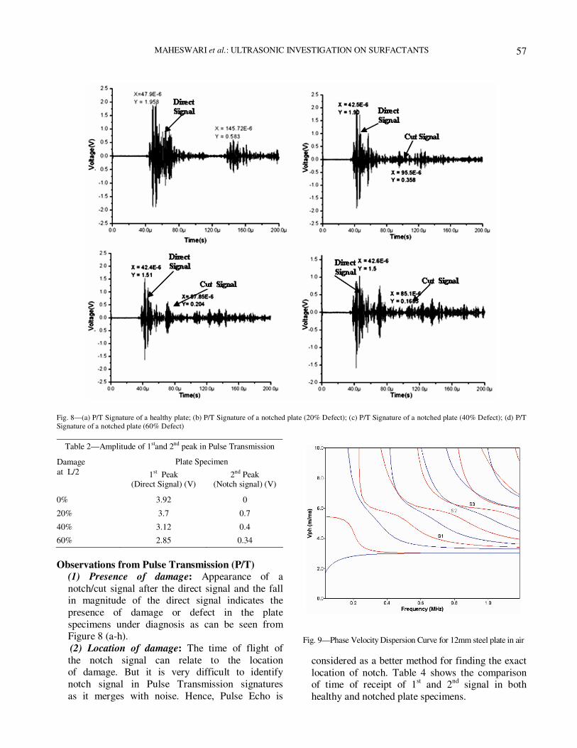
MAHESWARI et al.: ULTRASONIC INVESTIGATION ON SURFACTANTS
57
Fig. 8—(a) P/T Signature of a healthy plate; (b) P/T Signature of a notched plate (20% Defect); (c) P/T Signature of a notched plate (40% Defect); (d) P/T
Signature of a notched plate (60% Defect)
Table 2—Amplitude of 1stand 2nd peak in Pulse Transmission
Plate Specimen Damage
at L/2 1st Peak (Direct Signal) (V)
2nd Peak (Notch signal) (V)
0% 3.92 0
20% 3.7 0.7
40% 3.12 0.4
60% 2.85 0.34
Observations from Pulse Transmission (P/T)
(1) Presence of damage: Appearance of a
notch/cut signal after the direct signal and the fall in magnitude of the direct signal indicates the
presence of damage or defect in the plate
specimens under diagnosis as can be seen from Figure 8 (a-h).
(2) Location of damage: The time of flight of
the notch signal can relate to the location of damage. But it is very difficult to identify
notch signal in Pulse Transmission signatures
as it merges with noise. Hence, Pulse Echo is
considered as a better method for finding the exact
location of notch. Table 4 shows the comparison of time of receipt of 1
st and 2
nd signal in both
healthy and notched plate specimens.
Fig. 9—Phase Velocity Dispersion Curve for 12mm steel plate in air

J. PURE APPL. ULTRASON., VOL. 34, NO. 1 (2012)
58
Table 3—Comparison of Time of Flight in Pulse Echo
Theoretical Results (Disperse)*
State of specimen Time (µ sec)
1st peak 2nd peak
Healthy specimen -- 97
Notched specimen 44.4 88.8
Experimental Results
Time (µ sec) Notch Size
1st peak 2nd peak
0 % -- 99.6
20% 43.6 83.6
40% 45 83.4
60% 41 80.6
*Group Velocity of S3 mode in 12mm plate at 1 MHz = 4400 m/s
Table 4—Comparison of Time of Flight in Pulse Transmission (P/T)
Theoretical Results (Disperse)*
State of specimen Time (µ sec)
1st peak 2nd peak
Healthy specimen 48.8 --
Notched specimen 44.4 88.8
Experimental Results
Time (µ sec) Notch Size
1st peak 2nd peak
0 % 48 --
20% 42.5 95
40% 42.4 88
60% 42.6 85
*Phase Velocity of S3 mode in 12mm plate = 4400 m/s
(3) Magnitude of the damage: The extent of damage in plate can be ascertained by observing the peak-peak voltage trends of the 1
st peak
(Direct signal) received after traveling through length of specimens as well as 2
nd peak
(Cut Signal) which is obtained after reflection from the notch boundary. (i) Magnitude of the 1
st peak traveling through
the length of the specimens & that received after reflection from the crack boundary
relate well to the amount of damage. As the %age of damage increased from 0% to 60%, the magnitude of the 1
st peak reduces
continuously. (Figure 12). This is because of the reason that with increase in notch dimensions, more energy is reflected back and less travels through the specimen to reach at the other end.
(ii) Amplitude of the second peak (cut reflection) increased with the increase in % age of damage reduction upto 20 % damage signifying the increase in the defect in the
specimens as shown in Figure 12. Further
Fig. 10—Energy Velocity Dispersion Curve for a 12mm thick steel plate in air
Fig. 11—Pk-Pk voltage trends with increase in % damage in plates (Pulse Echo)
Fig. 12—Pk-Pk voltage trends with increase in % damage in plates (Pulse Transmission)

MAHESWARI et al.: ULTRASONIC INVESTIGATION ON SURFACTANTS
59
with the increase in notch damage there is slight fall in amplitude because major energy
is reflected from the large damage and very less reaches the other end. So the energy left for reflection from the large damage as 2
nd peak is very less.
Conclusions
The methodology established by the study utilizing
the Pulse Echo and Pulse Transmission techniques using ultrasonic guided wave modes (Symmetric
modes) at high frequencies can be utilized for damage
monitoring of plated structures with notched damages.
Symmetric guided modes in plates are preferred because of ease of excitation. Selection of a particular
mode (Higher Modes) is dependent on the type of
damage to be monitored. The technique not only indicates the presence of damage but also gives
the exact location and magnitude of damage by
efficient use of combination of pulse echo and pulse
transmission techniques.
Acknowledgements This research effort has been funded by Naval Research Board. Authors would like to express their
gratitude for the financial support provided by the funding agency.
References 1 Y. Bar-Cohen, Emerging NDT Technologies and challenges
at the beginning of third millennium, Part 1, Materials
Evaluation 58(1), 17-30 (2000) 2 J.G. Thompson, Subsurface corrosion detection in aircraft lap
splices using a dual frequency eddy current inspection technique, Materials Evaluation 51(12), 1398-1401(1993)
3 A.C. Kak, M. Slaney, Principles of computerized
Tomographic Imaging, IEEE Press, New York (1988) 4 X. Han, L.D. Favro, Z. Ouyang, R.L. Thomas,
Thermosonics: Detecting cracks and adhesion defects using ultrasonic excitation J. Adhesion , 151-162 (2001)
5 L.D. Favro, P.K. Kuo, R.L. Thomas, S.M. Shepard, Thermal wave imaging for aging aircraft inspection, Materials
Evaluation,51(12) 1386-1389 (1993) 6 S. Sharma, A. Mukherjee, Damage detection in reinforcing
bars in concrete using longitudinal guided waves, J. Pure
and Applied Ultrasonics, 31(3), (2009). 7 A. Mukherjee, S. Sharma, S. Sharma, Health Monitoring of steel
structures using ultrasonic waves, INSDAG Year Book 2009, 8 S. Sharma, P. C. Bhise, A. Mukherjee, Damage detection in
reinforcing bars in concrete using ultrasonic guided waves: An experimental and analytical study, J. Structural
Engineering, CSIR-SERC, Chennai, 37(6), 409-421(2010).
9 B.N. Pavlakovic, P. Cawley, DISPERSE User’s Manual
Version 2.0.1.1, Imperial College, University of London (2000)

J. Pure Appl. Ultrason. 34 (2012) pp 60-63
Study of Ultrasonic parameters of Aqueous solutions of Phloroglucinol
*1D.Muraliji and 2 G.Karthikeyan 1P.G & Research Dept. of Physics, Periyar E.V.R College (Autonomous), Tiruchirapalli-23.
2 Rajah Serfoji Government College (Autonomous), Thanjavur -5. Email:- [email protected]
Phloroglucinol ( 1,3,5-Trihydroxy benzene ) is used in the preparation of pharmaceuticals, dyes and resins. It is also used in the preparation of cut flowers, textile dyeing and printing and in analytical chemistry. Ultrasonic parameters provide valuable information about various inter and intra molecular interactions in solutions. Ultrasonic velocity, density
and viscosity of aqueous solutions of Phloroglucinol at various concentrations and at various temperatures ranging from 303K to 323K have been experimentally determined. Ultrasonic parameters such as Acoustical impedance, Adiabatic compressibility, Intermolecular free length, Rao’s constant, Wada’s constant, Acoustical relaxation time, Relative association, Available volume and Vander Waal’s constant of these solutions are computed on the basis of these measurements. Various molecular interactions in these solutions have been analyzed on the basis of the variations of these parameters with concentration and temperature.
Introduction
Ultrasonic velocity measurements provide an
important tool to study the liquid state. The measurement of ultrasonic velocity in liquids and
liquid mixtures provide valuable information about
their physico-chemical properties and the nature of molecular interactions in them
1-3.
Different ultrasonic parameters have been
calculated with a view to investigate the exact nature
of the molecular interactions4,5
. Phloroglucinol is used in the preparation of
pharmaceuticals, dyes and resins. It is also used in the
preservation of cut flower, textile dyeing and printing and in analytical chemistry
6.
Aqueous solutions have gained importance due to
their vast usage. In the present study, ultrasonic and
thermodynamic parameters of aqueous solutions of Phloroglucinol at various concentrations and at
different temperatures ranging from 303K to328K
have been evaluated. The results obtained are analyzed.
Experimental study
Computations of ultrasonic and thermodynamic properties require the measurement of ultrasonic
velocity (u), viscosity (η) and density (ρ) Aqueous solutions of Phloroglucinol with various
concentrations are prepared by dissolving its AnalaR
grade salt in double distilled water.
Ultrasonic velocity through the solution is
measured with an ultrasonic interferometer with
an accuracy of + 2 m/s. The cell temperature is
maintained with a circulating ultra thermostat
accurate to within 0.1K. The density of the
solution is measured with 10 ml specific gravity
bottle. The viscosity of the solution is determined
using a Cannon-Fenske viscometer.
Computation Various ultrasonic and thermodynamic parameters
used in the present study are computed using the
following relations7.
1). Acoustical impedance (Z) is calculated by the relation
Z = ρu kg.m-2.s
-1 (1)
2). Adiabatic compressibility (βs) is evaluated using the formula
βs = 1/ u2ρ Pa
-1 (2)
3). Intermolecular free length (Lf) is obtained using
the relation
Lf = Kβs1/2
Å (3)
4). Molar sound velocity (or) Rao’s constant (R)
is evaluated using the relation
R = ( Meff /ρ ) u1/3
(m3/mol) (m/s)
1/3 (4)
5). Molar compressibility (or) Wada’s constant
(W) is obtained using the relation
W = ( Meff /ρ ) βs-1/7
(m3/mol).Pa
1/7 (5)
6). Acoustical relaxation time (τ) is evaluated using the formula
τ = 4η / 3ρu2
s (6)

MURALIJI & KARTHIKEYAN: ULTRASONIC PARAMETERS OF PHLOROGLUCINOL
61
7). Relative association (RA ) is obtained making use
of the formula
RA = ( ρ / ρ 0 ) ( u 0 / u )1/3
(7)
8). Available volume ( Va ) is calculated using the formula suggested by Schaafs
Va = ( Meff /ρ ) ( u / u ∞ ) m3.mol
-1 (8)
9). Van der Waal’s constant ( b ) is computed using
the formula
b = ( Meff /ρ ) [{1-( RT / Meff u2 )}{ 1+ (Meff u
2
/3RT)}1/2
– 1 ] m3/mol (9)
where R is the gas constant, T is the temperature in Kelvin, k is a constant of value 4.28x10
-9,
u ∞ =1,60,000 cm.s-1
, Meff is the effective mass and
ω = 2π f where f is the frequency of the ultrasonic waves used.
The parameters obtained from the above study are
summarized in Tables 1&2.
Results and discussions
Ultrasonic velocity is found to increase with increase in temperature (Fig.1). It also shows
variations with increase in concentration. These
indicate interactions between solute and solvent
molecules8. At 303K, 313K and 318K the ultrasonic
velocity shows a sudden increase at 0.03m. This
effect is more marked at 318K. These indicate
molecular association of solute and solvent molecules is maximum at this molality for these temperatures
9.
Acoustical impedance (Z) shows a trend similar to
ultrasonic velocity (Fig. 2). At 303K, 313K, 318K and
323K, the acoustical impedance has peak values at 0.03m. This phenomenon is more marked at 318K.
Increase in acoustical impedance show that the
molecular interactions in these solutions is associative
9. Adiabatic compressibility is the
fractional decrease in volume per unit raise in
pressure when no heat flows in or out. Increase in its
value indicates weaking of molecular interactions.
Adiabatic compressibility of Phloroglucinol exhibits an opposite trend to that of its ultrasonic velocity
(Fig. 3), This is in accordance with the earlier study
by the authors7.
Intermolecular free length (Lf) is the distance between the surfaces of the neighboring molecules.
Variation of intermolecular free length with
concentration and temperature is shown in Fig. 4. It shows variation with both temperature and
concentration. For all the temperatures, except at
308K, there is a sudden dip at 0.03m. Further, it is
found that this effect is more marked at 313k and
Fig. 1—Molality vs ultrasonic velocity
Fig. 2—Molality vs acoustical impedance
Fig. 3—Molality vs adiabatic compressibility
Fig. 4—Molality vs int.mol, free length

J. PURE APPL. ULTRASON., VOL. 34, NO. 1 (2012)
62
318K. This indicates maximum molecular interactions
at 0.03m8.
From the observations on Molar sound velocity or Rao’s constant (R) (Fig. 5 ), a general increase with
rise in temperature is noted. It is also found to vary
with concentration. At 303K and 308K Rao’s constant
shows decrease with increase in concentration up to 0.02m and it increases on further increase in
concentration. At 313K, its value increases with
concentration up to 0.02m and remains constant thereafter. At 318K, Rao’s constant shows variation
with change in concentration. These indicate the
presence of molecular interactions in the solutions.
Molar compressibility or Wada’s constant shows increase with increase in temperature and variations
with change in concentration (Fig. 6). The trend of
variation changes at 318K and shows a peak at 0.03m.These indicate that molecular interactions are
maximum at 0.03m for 318K.
Acoustical relaxation time (τ) is found to decrease with increase in temperature and varies with changes
in concentration (Fig. 7). A comparative study of adiabatic compressibility and acoustical relaxation
time indicate that the variations in acoustical
relaxation time are mainly due to the changes in the viscosity of the solutions due to both concentration
and temperature.
Relative association (RA) (Fig. 8) shows a general
decrease with increase in temperature. It is found to
be nearly equal to unity and variations in it value indicate molecular interactions.
Available volume (Va) of Phloroglucinol (Fig. 9)
shows a general decrease with increase in temperature
and non-linear variations with change in concentration. At 303K, 313K and 318K it shows a
maximum value at 0.03m, with this effect being
maximum at 318K. Variations in available volume are found to be opposite to that the variations in
ultrasonic velocity of the solutions..
Van der Waal’s constant (b) (Fig. 10) is found to
vary with concentration and temperature.Variations
Fig. 5—Molality vs molar sound velocity (or) Rao’s constant
Fig. 6.—Molality vs molar compressibility (or) Wada’s constant
Fig. 7—Molality vs acoustical relaxation time
Fig. 8—Molality vs relative Association
Fig. 9. —Molality vs available Volume

MURALIJI & KARTHIKEYAN: ULTRASONIC PARAMETERS OF PHLOROGLUCINOL
63
due concentration is more prominent. Increase
in the value of Van der Waal’s constant indicate increase of attractive forces resulting
due to strong association between solute and
solvent molecules. The results obtained are compared with those
of aqueous solutions of Pyrogallol done by
earlier researchers10
. While variations of
acoustical relaxation time of aqueous solutions of Phloroglucinol and Pyrogallol with concentration
and temperature are almost similar, the variations
of ultrasonic velocity, acoustical impedance, adiabatic compressibily, intermolecular free
length, molar sound velocity, molar compressibility,
available volume and Van der Waal’s constant
of these solutions are different.
References 1 Batt.S.C., Harikrishnan Semwal, Vijendra Lingwal, Kuldeep
Singh and Semwal.B.S., Acoustical Parameters of Some Molecular Liquids, J.Acous.Soc.India, 28(2000) 293-296.
2 Dhanalakshmi.A. and Sekar.S., Internal pressure and thermodynamic property studies in Insulin,J. Pure Appl.
Ultrason. 21 (1999) 97.
3 Sastry.G.L.N., Ultrasonic studies of binary liquid mixtures J.Acous.Soc. India. 14 (1986) D9-1 to D9-8.
4 Bhatt.S.C., Harikrishnan Semwal., Vijendra Lingwal., Kuldeep Singh and Semwal.B.S., Acoustical parameters of
some molecular liquids, J.Acous.Soc.India, 28(2000) 275-278.
5 Muraliji.D., Sekar.S., Dhanalakshmi.A. and Ramkumar.A.R. “Study of Ultrasonic velocity and Thermodynamic parameters of Vanillin. J.Pure and Appl. Ultrasonics, 24
(2002 ) 63-67.
6 Richard J.Lewis, Sr., “ Hawley’s Condensed Chemical
Dictionary ”, Thirteenth Edn., Golgotta Publications, New Delhi,2000.
7 Muraliji.D., Sekar.S., Dhanalakshmi.A. and Ramkumar.A.R. “Study of Ultrasonic velocity and Thermodynamic parameters of Nitrophenols, J. Acous. Soc. India. 29 (2001 ) 275-281.
8 Jayakumar.S, Tabhane.V.A. , Karunanidhi.N., Kannappan.V.
and Subramanian.S., Molecular Interactions Between Electron Donor and Acceptor, J. Acou. Soc. India. 28 No.1-4 (2000) 373-375.
9 Tabhane.V.A., Sangeeta Agrawal and Revetkar.K.G. , Ultrasonic Studies of Binary Liquid Mixtures of Cinnamaldehyde in Methanol, Acetone and Cyclohexane, J. Acou. Soc. India. 28 ( 2000) 369-371.
10 Rani.G., “ Proton Magnetic Resonance – Relaxation time, Internal pressure, Free volume, Hydration number and Thermodynamic analysis of Phenols, Sugars and Sugar alcohols“. Ph.D. Thesis, Bharathidasan University, 2000.
Fig. 10—Molality vs van der Waal’s Constant

J. Pure Appl. Ultrason. 34 (2012) pp. 64-65
Conference Report on National Seminar on Materials Characterization
by Ultrasonics (NSMCU-2012)
Amity School of Engineering and Technology, Bijwasan, New Delhi organized a two day National
Seminar on Materials Characterization by Ultrasonics (NSMCU-2012) during April 3-4, 2012;
which was inaugurated by Dr. V.R. Singh, Vice-President, Ultrasonics Society of India. The eminent
dignitaries present in the inaguration included. Prof. B.P. Singh, Senior Director, Amity School of
Engineering and Technology, Bijwasan; Dr. V. K. Jain, Former Director Level Scientist, SSPL
(DRDO) and Director, Amity Institute of Advanced Research and Studies, Amity University Uttar-
Pradesh; Prof. Raja Ram Yadav, Department of Physics, University of Allahabad and Prof. (Dr.)
Rekha Agarwal, Director, Amity School of Engineering and Technology, Bijwasan. The seminar
was conducted in association with the Ultrasonics Society of India. The objective of the seminar was
to provide a strong platform to bring scientists, engineers, technocrats, medical practitioners,
researchers, industries, etc. for mutual exchange of views, knowledge and planning for the future
development on various topics of ultrasonics, which are very useful in overall and healthy growth of
society. The topics covered in this seminar were: ultrasonic instrumentation, sensors and transducers,
biomedical ultrasonics, physical acoustics, signal processing, underwater ultrasonics, ultrasonic
standards and calibrations, ultrasound in nanoscience and technology, laser ultrasonics and many
more related to the subject.
In the inaugural function, Dr. Devraj Singh, Convener: NSMCU-2012 introduced the objective
and focal themes of the seminar. Professor B. P. Singh welcomed the delegates, guests and sponsors,
and explained importance of ultrasonics in research and in medical and industrial applications. He
expressed hope that this seminar would provide an opportunity to all the participants to share their
views on the latest development in the area of ultrasonics and its applications. In his inaugural talk
Dr. V.R. Singh, he gave an introduction of ultrasonics, its utilization and progress. He stressed that
students of ultrasonics should learn about high power and low power ultrasonics to get equipped with
recent as well as prospective technology. Dr. Singh also averred on future technological trends and
development of nano-ultrasonic system and ultrasonic biotelemetry technology. He outlined the
benefits of using ultrasound in agriculture, which would make bulk management and food processing
fairly simpler. This was followed by a talk from the eminent scientist, Dr. V.K. Jain, who gave an
insight in the process of characterization of materials and discussed different techniques of material
characterization especially for application in electronic devices.
The Keynote talk was delivered by Prof. Raja Ram Yadav on “Behaviour of Ultrasonic Wave
Propagation in Materials”. He outlined the use of ultrasonics in various disciplines of scientific and
technological applications including those for medical and diagnostic purposes. He also explained
the progress being made by Indian Scientists in efforts to extract optimum research output using
ultrasonics. Ultrasonics can identify the characteristics of a material by studying the behaviour of
ultrasonic propagation. Prof. Yadav outlined the difference between X-rays and Ultrasonic waves,
with their benefits and setbacks. He averred about the recent advances the ultrasonic engineering has
attained and mentioned that it is ready to enter the field of Nanotechnology, to benefit especially the
medical science. As an example, he said cancer treatment may be possible through nanoparticles, the
characteristics of which can be studied through ultrasonic wave propagation. Finally, Prof. Yadav
encouraged the longstanding view of ultrasonic scientists to make ultrasonic engineering a part of
engineering courses.
The scientific program of the seminar was divided in ten sessions including two poster sessions,
which had one chairperson and one co-chairperson each. The participants came from twenty cities
and eight states of the country and presented (17 invited talk, 13 Oral presentation and 19 poster
presentation) papers covering a wide variety of topics related to ultrasonic science and technology.

J. PURE APPL., ULTRASON., VOL. 34, NO. 3 (2012)
65
Dr. V. R. Singh in his invited talk on “Recent Advances in Ultrasonic Characterization of
Cancerous Biological Tissues” highlighted the merits and limitations of various modalities available
today. “Molecular Interaction Effecting Changes in Molecular Shapes: Scaled Particle Theory” was
explained by Professor Vilas A Tabhane (University of Pune). Prof. V.K.Syal (Former Professor and
Chairman, Department of Chemistry, H.P. University, Shimla) gave a brief review on “Ultrasonic
Velocity Studies of Molecular Interactions in Solvent Mixtures and Electrolyte Solutions” for the
study of nature and strength of molecular interactions in liquid mixtures and electrolytic solution. Dr.
P.Palanichamy highlighted some important development works carried out at IGCAR on ultrasonic
characterization of microstructures in a variety of nuclear materials such as AISI type 316 austenitic
stainless steel, modified alloy D9 and Zircaloy-2. An elaboratory talk on “Study of Ultrasonic
Attenuation using Two State Model” was presented by Professor V.K. Pundhir of SIRT-Excellence,
Bhopal. Dr. Kanwar Jit Singh, Department of Physics, GND University, Amritsar delivered his talk
on “Surface Acoustic Wave Device for Hydrogen Gas Sensing”. He described how surface acoustic
wave device is useful for hydrogen gas sensing, which can be important for use of hydrogen gas as
fuel in automobiles. Dr. Jitendra N. Ramteke of SM Mohota College of Science, Nagpur gave a talk
on “Theoretical Computation of Ultrasonic Velocity in Liquids”, in which he discussed various
aspects to compute propagation parameters for liquid and binary liquids. Dr. Mahavir Singh, NPL
presented an exciting talk on “Development of Lightweight Sandwich Material as Acoustic Partitions
for Building Applications”. He presented a study of sound transmission lightweight partition,
especially those usually called sandwich type and its experimental applications to a new and very
specific kind of partition made of gypsum board and cork, traditional material in India.
A number of other interesting talks were given by Dr. Kailash (Rath), Dr. Rajeev K Shukla
(Kanpur), Dr. Y.K. Yadav (NPL), Dr. D.K. Pandey (Kanpur), Dr. A.K.Gupta (NIOS, Noida),
Dr. A.K. Yadav (Lucknow) and others. The contributory papers were delivered during parallel oral
and poster sessions.
There was a panel discussion at the end of the scientific sessions on the second day, which was
moderated by Professor B.P. Singh, Senior Director. He gave an overview of the significant
presentations made, such as ultrasonic studies on microstructure, nano-particles, saw devices, etc.
and he expressed hope that the deliberations at the seminar would inspire and extend the reach of
students of undergraduate and PG levels for research and development work.
Five papers were selected as “BEST PAPERS”, which are as follows:
1. “A Fully Automated Precise Measurement System for Ultrasonic Velocity and Attenuation in
Solids Down to Liquid Helium Temperatures and Magnetic Field ± 14 Tesla using Pulse
Transmission Technique” by Saurabh Singh, UGC-DAE-Consortium For Scientific Research,
Khandwa Road, University Campus, Indore-452001 (M.P).
2. “Ultrasonic Studies on Nanosized Zinc Oxide and its Nanofluid” by D.K.Singh, Department of
Physics, Government Inter College, Bangra, Jalaun-285121
3. “Ultrasonics of Binary Mixture and its Excess Values at 303.15 K” by Prashant Dabrase, Dept.
of Physics, Government Institute of Science, Nagpur
4. “An Ultrasonic study of LaSb, YbP and YbAs at high temperatures” by D. K. Pandey,
Department of Physics, P.P.N. (P.G.) College, Kanpur-208 001, India
5. “Acoustic Properties of Coconut Coir Fibre Sound Absorption Materials” by Dharam Pal Singh,
Acoustic Section, National Physical Laboratory.
During the valedictory function on 4th April, 2012 the Chief Guest, Prof. Vilas A Tabhane
(University of Pune), expressed his happiness over the professional approach adopted in organizing
this seminar. He stressed upon the need to pursue more R & D activities in applied and vast
expanding field of ultrasonics. All the participants had a good time enjoying cultural evening on 3rd
April, 2012.
Dr. Devraj Singh
Convener, NSMCU-2012, Department of Applied Sciences
Amity School of Engineering and Technology,
Bijwasan, New Delhi

66
Forthcoming Events and Conferences Compiled by Mahavir Singh & S.K. Jain CSIR-NPL, New Delhi
[email protected], [email protected]
1 – 5 July, 2012, Lviv University, Ukraine, 13th
Meeting of European Society of Sonochemistry
http://www.ess13.org
02 - 06 July 2012, Edinburgh, UK, 11th European Congress on Underwater Acoustics
http://www.acua2012.com
08 - 12 July 2012, Vilnius, Lithuania, 18th
International Congress on Sound and Vibration
(ICSV19) http://www.icsv19.org
11 – 13 September, 2012, Daventry, U.K., 51st Annual Conference of British Institute of NDT
http://www.bindt.org
12 - 15 September, Granada, Spain 30th European Conference on Acoustic Emission Testing
(EWGAE) and the 7th International Conference on Acoustic Emission (ICAE)
http://2012.ewgae.eu/
7 – 10 October, 2012, Dresden, Germany, 2012 IEEE International Ultrasonics Symposium
http://www.ieee.org
30 – 31 October, 2012, New Delhi, India, XIX National Symposium on Ultrasonics
19 - 21 November, Aachen, Germany Aachen Acoustics Colloquium
http://www.aachen-acoustics-colloquium.com/
2 – 5 December, 2012, Tiruchengode, India, National Symposium on Acoustics
17 - 20 March, Les Arcs, France Electroceramics for End-users VII (PIEZO 2013)
http://www.piezoinstitute.com
1 - 4 May, Singapore 3rd International Congress on Ultrasonics (ICU 2013)concurrently organized
with the 32nd International Symposium on Acoustical Imaging (AI 2013)
http://www.epc.com.sg/PDF Folder/ICU 2010 Phamplet v1 (12 Jul 2010).pdf
02 - 07 June, Montreal, Canada 21st International Congress on Acoustics (ICA 2013)
http://www.ica2013montreal.org