journal of structural geology - umass lowellfaculty.uml.edu/nelson_eby/89.520/professional...
TRANSCRIPT
lable at ScienceDirect
Journal of Structural Geology 97 (2017) 104e117
Contents lists avai
Journal of Structural Geology
journal homepage: www.elsevier .com/locate/ jsg
The effect of water on strain localization in calcite fault gouge shearedat seismic slip rates
Marieke Rempe a, *, Steven Smith b, Thomas Mitchell c, Takehiro Hirose d,Giulio Di Toro a, e, f
a Universit�a degli Studi di Padova, Dipartimento di Geoscienze, Via G. Gradenigo, 6, 35131, Padova, PD, Italyb University of Otago, Department of Geology, Dunedin, 9054, New Zealandc University College London, Rock & Ice Physics Laboratory and UCL SeismoLab, Department of Earth Sciences, London, WC1E 6BT, UKd Kochi Institute for Core Sample Research, JAMSTEC, 200 Monobe Otsu, Nankoku-shi, Kochi, 783-8502, Japane University of Manchester, School of Earth, Atmospheric & Environmental Sciences, Oxford Road, Manchester, M13 9PL, UKf Istituto Nazionale di Geofisica e Vulcanologia (INGV), Via di Vigna Murata 655, Rome, Italy
a r t i c l e i n f o
Article history:Received 22 July 2016Received in revised form8 February 2017Accepted 18 February 2017Available online 21 February 2017
Keywords:Fault gougeLocalizationCalciteRotary-shear experimentsEarthquakesDynamic weakening
* Corresponding author. Now at: Ruhr-UniversitaetMineralogy and Geophysics, Universtitaetsstr. 150, 44
E-mail addresses:[email protected] (M. Remp(S. Smith), [email protected] (T. Mitchell), [email protected] (G. Di Toro).
http://dx.doi.org/10.1016/j.jsg.2017.02.0070191-8141/© 2017 Elsevier Ltd. All rights reserved.
a b s t r a c t
Strain localization during coseismic slip in fault gouges is a critical mechanical process that has impli-cations for understanding frictional heating, the earthquake energy budget and the evolution of faultrock microstructure. To assess the nature of strain localization during shearing of calcite fault gouges,high-velocity (vmax ¼ 1 m=s) rotary-shear experiments at normal stresses of 3e20 MPa were conductedunder room-dry and wet conditions on synthetic calcite gouges containing dolomite gouge strainmarkers. When sheared at 1 m/s, the room-dry gouges showed a prolonged strengthening phase prior todynamic weakening, whereas the wet gouges weakened nearly instantaneously. Microstructural analysisrevealed that a thin (<600 mm) high-strain layer and through-going principal slip surface (PSS) devel-oped after several centimeters of slip in both dry and wet gouges, and that strain localization at 1 m/soccurred progressively and rapidly. The strain accommodated in the bulk gouge layer did not changesignificantly with increasing displacement indicating that, once formed, the high-strain layer and PSSaccommodated most of the displacement. Thus, a substantial strain gradient is present in the gouge layer.In water-dampened gouges, localization likely occurs during and after dynamic weakening. Our resultssuggest that natural fault zones in limestone are more prone to rapid dynamic weakening if water ispresent in the granular slipping zones.
© 2017 Elsevier Ltd. All rights reserved.
1. Introduction
Field and trench observations from large fault zones show thatwhile the surface trace of a fault can have a complex and broadlydistributed geometry (Rockwell and Ben-Zion, 2007), co-seismicslip at depth is often localized within subcentimeter-thick gouge-and cataclasite-bearing principal slip zones (Sibson, 2003). There isalso evidence that within these principal slip zones, localization tothe sub mm-scale takes place during individual coseismic slipevents (e.g., Chester et al., 1993; Chester and Chester, 1998; Boullier
Bochum, Institute of Geology,801, Bochum, Germany.e), [email protected]@jamstec.co.jp (T. Hirose),
et al., 2009; Fondriest et al., 2012, 2013; Siman-Tov et al., 2013;Smith et al., 2013), although distributed coseismic deformation alsooccurs, e.g. at fault irregularities (Sibson, 1986; Pavlis et al., 1993;Aben et al., 2016).
The degree of strain localization and the thickness of the activeprincipal slip zone strongly influence the dynamic behavior offaults (Ben-Zion and Sammis, 2003; Heermance et al., 2003;Rockwell and Ben-Zion, 2007), including the production of fric-tional heat and the evolution of thermally-sensitive weakeningmechanisms. For example, Platt et al. (2014) modeled the shearstrength evolution of a fluid-saturated gouge layer sheared atseismic slip rates (1 m/s), taking into consideration the role ofthermally-driven weakening mechanisms. They found that duringthe early stages of deformation the shear strength evolution issimilar to that modeled for uniform shearing (Rempel and Rice,2006), but the onset of strain localization is accompanied by an
M. Rempe et al. / Journal of Structural Geology 97 (2017) 104e117 105
acceleration in dynamic weakening because localization focusesfrictional heating into a thinner zone and consequently thermalpressurization becomes more effective (Lachenbruch, 1980).
In high-velocity experimental studies on gouge layers, shearlocalizes to a thin (<300 mm) and highly-comminuted slip zone cutby one or more discrete slip surfaces (Han et al., 2010; Kitajimaet al., 2010; De Paola et al., 2011; Fondriest et al., 2013; Smithet al., 2015). Evidence of intense strain localization and frictionalheating is preserved as zones containing gouge material that isultracomminuted, decomposed, recrystallized or sintered (e.g.,Sawai et al., 2012; Togo and Shimamoto, 2012; Smith et al., 2013;Yao et al., 2013). The observed dynamic weakening that accom-panies strain localization has been attributed to flash heating in athin (�30 mm) layer of wear material (Goldsby and Tullis, 2011;Kohli et al., 2011) or rapid diffusional processes in nanograinsaccompanying superplastic behavior (Verberne et al., 2013, 2014b;De Paola et al., 2015; Green et al., 2015). In the case of carbonaterocks, flash weakening could be enhanced by decarbonation due tofrictional heating and formation of CaO nanograins (Han et al.,2007, 2010; Violay et al., 2014). The formation of nanograin mate-rial may be responsible for the velocity-weakening behavior ofcarbonate gouges sheared at low velocity (~1 mm) and elevatedtemperatures of 80e100 �C (Verberne et al., 2010, 2014a, 2014b) aswell as for the low steady-state shear stress at high velocity (c. 1 m/s; De Paola et al., 2015; Green et al., 2015) due to enhancement ofgrain boundary sliding mechanisms.
Results from high-velocity experiments on room-dry calcite(Smith et al., 2015) and serpentinite (Proctor et al., 2014) gougesshowed that strain was localized to a high-strain shear band priorto dynamic weakening, consistent with the idea that extremelocalization in gouges is a necessary precursor to dynamic weak-ening (Goldsby and Tullis, 2011). However, the effect of water onlocalization and dynamic strength evolution in carbonate gougeshas not yet been studied. This is important because field studies ofnatural slip zones in carbonates have shown that localized slip iscommonly associated with the formation of veins and micro-structures that indicate gouge fluidization (Smith et al., 2011; DePaola et al., 2012; Fondriest et al., 2012; Rowe et al., 2012), sug-gesting that in many carbonate-bearing fault zones coseismic slipoccurs in the presence of hydrous fluids. The presence of water wasfound to significantly decrease the strength of clay-bearing gougessheared at low to high velocities (Morrow et al., 2000; Kitajimaet al., 2010; Ujiie and Tsutsumi, 2010; Faulkner et al., 2011; Hanand Hirose, 2012; Verberne et al., 2014a; Bullock et al., 2015). Theaim of this experimental study was to understand the strain-localization process in wet calcite gouges. To this end, we con-ducted rotary-shear experiments over a wide range of total dis-placements on dry and wet calcite gouges including the systematicuse of strain markers.
2. Material and methods
Two different rotary-shear apparatus were used in this study:the Slow-to High Velocity Apparatus (SHIVA; Di Toro et al. (2010))installed at the Istituto Nazionale di Geofisica e Vulcanologia inRome, Italy, and the Pressurized High-Velocity apparatus (Phv)installed at the Kochi Institute for Core Sample Research/JAMSTECin Nankoku, Japan (Tadai et al., 2009; Tanikawa et al., 2012). Thegouge holder used in conjunction with SHIVA allowed us to easilyconstruct a strain marker within the gouge layers, but pore-fluidconditions could not be controlled. Experiments under controlledpore-fluid conditions were performed using the Phv apparatus,which is equipped with a servo-controlled pore-fluid pressuresystem. Using the two different apparatus provides the additionaladvantage of being able to test the reproducibility of the
mechanical data.
2.1. Experimental Set-Up of the SHIVA apparatus
A total of 18 high-velocity, rotary-shear experiments were per-formed with SHIVA using strain markers (Table 1). The gouge ex-periments were performed at a target maximum slip rate of 1 m/s,acceleration and deceleration of 6 m/s2, normal stresses rangingfrom 3 to 20 MPa, total displacements from 0.011 to 2.5 m, andunder room-dry or water-dampened conditions (Table 1). Thedesign and capability of SHIVA are described in Di Toro et al. (2010)and Niemeijer et al. (2011). The annular gouge holder used withSHIVA (description and calibration tests in Smith et al., 2013) isbuilt mainly from steel. The gouge layer has inner and outer di-ameters of 35 and 55mm and is contained above and below by basediscs and to the sides by steel rings that slide over the upper basedisc (Fig. 1a). As the confining rings are in contact with the basediscs, but are not designed to carry load, springs located under-neath the rings ensure that the normal load is mainly supported bythe gouge layer (Smith et al., 2013). To minimize the contribution ofthe sliding rings to the measured torque, the contact area of therings with the base disc was lubricated with high-temperaturegrease prior to each experiment. The axial displacement of thegouge layer, i.e. its compaction or dilation, was measured using aDCDT (Direct Current Differential Transformer) with a resolution ofc. 50 mm, which is installed on the stationary axis. The axialdisplacement as well as the torque, normal load, rotation velocityand displacement were measured with a sampling rate of 25 kHz.
2.2. Experimental Set-Up of the “Pressurized high-velocity” (“Phv”)apparatus
A total of 24 high-velocity, rotary-shear experiments were per-formed with the Phv apparatus under room-dry and controlledpore pressure conditions (Table 2). Experiments with the Phvapparatus were also performed at a targetmaximum slip velocity ofc. 1 m/s but with a slower acceleration of 0.5 m/s2. Additionally, insome experiments the gouge samples were pre-sheared for adisplacement of c. 30 cm at a velocity of 1 mm/s (Table 2). Thegouge holder used with the Phv apparatus has inner/outer di-ameters of 30 and 60 mm.
Pore fluid in the Phv apparatus is introduced to the gouge layer(marked yellow in Fig. 1b) through the stationary part of the gougeholder (grey parts in Fig. 1b). The fluid outlet is located in the centerof the annular holder; thus, the pore fluid has to pass through thegouge material before passing into the fluid-outlet tube in the ro-tary part of the gouge holder (white parts in Fig. 1b) and furtherinto the outlet tube within the stationary part. The saturated gougeis confined with inner and outer Teflon sleeves and several o-rings(Fig. 1b). Fluid pressure is monitored upstream and downstream ofthe sample using two pressure gauges and is adjusted via a servo-controlled moving piston. As the pressure gauges are locatedoutside the sample chamber, the pore pressure cannot be perfectlycontrolled. Applied effective normal stresses and pore-fluid pres-sures ranged from 3 to 12 MPa and from 0.2 to 10.5 MPa, respec-tively (Table 2). The experiments were performed with room-dryand water-saturated calcite gouges, but without the use of strain-markers. The experimental data were recorded at a sampling rateof 1 kHz.
2.3. Sample preparation and analysis techniques
The calcite gouge was derived by crushing pieces of Carraramarble. The dolomite gouge used for the strain markers in theSHIVA experiments was derived by crushing cohesive dolostones

Table 1Experiments performed with SHIVA. Experimental conditions applied in the a) room-dry and b) water-dampened strain-marker experiments. Equivalent target slip rate was1 m/s in all experiments.
Experiment Normal stress(MPa)
Total equivalentdisplacement (m)
Appliedbulk straina
Max. bulk strain rate(1/s)a
Thickness(mm)c
Initial thickness(mm)e
a) Room-dry s897 3 0.29 128 441 2.14 2.27s886 3 2.5 1295 518 1.8 1.93s873 8.5 0.08 32 400 e e
s953 8.5 0.13 60 463 1.41 2.16d
s871 8.5 0.28 112 400 e e
s887 8.5 0.29 109 376 2.5 2.66s881 8.5 0.43 195 452 2.02 2.21s1013 8.5 0.43 172 400 e e
s952 8.5 0.5 200 400 e e
s896 8.5 1.3 442 340 2.6 2.94s943 8.5 1.3 551 424 2.1 2.36s875 15 0.14 56 400 e ed
s889 20 0.29 141 488 1.93 2.05d
b) Water-dampenedb s959 8.5 0.011 6 230 1.64 1.74s895 8.5 0.2 80 400 e 0.9d
s961 8.5 0.43 228 529 1.74 1.89s898 8.5 1.5 732 488 1.9 2.05s962 8.5 2.1 1148 546 1.55 1.83s279f 17.3 2.82 1128 400 e e
s389f 21 1.015 406 400 e e
a If no initial sample thickness could be calculated, a thickness of 2.5 mm was assumed.b 20 wt% distilled H2O.c Thickness of sheared gouge layer evaluated from the SEM pictures.d Material loss during sample preservation.e Obtained from c and the amount of compaction measured during the experiment.f No strain marker.
M. Rempe et al. / Journal of Structural Geology 97 (2017) 104e117106
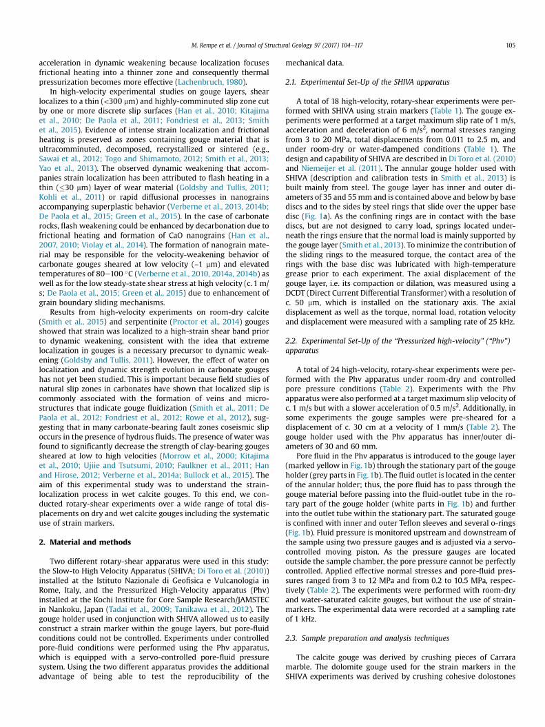
from the Foiana Tectonic Line (Fondriest et al., 2013). Both gougeswere sieved to particle sizes <250 mm. For the experiments per-formed with SHIVA, 5 g of calcite gouge were distributed inside thegouge holder yielding a gouge layer thickness of c. 3 mm. After-wards a c. 2 mm wide, subvertical (approx. ±20�) dolomite strainmarker was constructed perpendicular to both the imposed sheardirection and the gouge layer boundaries (Fig. 2a). For SHIVA ex-periments with water-dampened gouges, 1 ml of distilled H2O wasadded evenly to the top surface of the gouge layer using a pipette.The gouge was then pre-compacted using a pneumatic pressyielding an initial gouge layer thickness of ca. 2.5 mm (Fig. 2a). ForPhv experiments, 15 g of calcite gouge were used to obtain a gougelayer thickness of c. 3 mm. The gouge layer was pre-saturated byadding distilled water using a pipette. Full saturation was achievedusing the pore-pressure system as described above.
After each experiment performed with SHIVA, a sample of thegouge layer containing the sheared strain marker was preserved inresin and cut (using a water-cooled saw) subparallel to the sheardirection to obtain a cross-section through the sheared strainmarker (Fig. 2b and c). Due to the annular sample geometry,maximum slip velocity and total displacement vary inside thegouge layer depending on the radial position. In the following, wethus report the “equivalent” velocity and displacement followingHirose and Shimamoto (2005). When preparing the sample, carewas taken to cut the different samples at approximately the sameradial positions to produce comparable results in terms of micro-structural analysis and strain measurements.
Polished samples were coated with carbon or chrome formicrostructural analysis using a JEOL JSM-6500F Field-EmissionScanning Electron Microscope (SEM) at the Istituto Nazionale diGeofisica e Vulcanologia (INGV) in Rome, Italy, a CamScan MX3000SEM at the University of Padua and a LEO (Zeiss) 1530 Gemini Highresolution thermally-aided Field Emission SEM at the Institute ofGeology, Mineralogy and Geophysics of the Ruhr-Universit€atBochum, Germany. Images were obtained in backscattered electronmode using an acceleration voltage of 8e20 kV and a working
distance of 7.3e20 mm. In backscattered mode, the dolomitemarker is easily distinguished from the surrounding calcite due toits darker grey color (Fig. 2a). The marker is sheared in the directionof slip and the finite strain g at different positions within the gougelayer can be calculated from the angle of distortion 4 using therelation g ¼ tan 4 ¼ dx=x, where x is the thickness of the layer anddx the amount of horizontal displacement (Fig. 2d and e).
3. Results
3.1. Mechanical behavior of room-dry and water-dampened calcitegouges
In SHIVA experiments, the evolution of shear stress t withdisplacement is highly reproducible for experiments conductedunder the same conditions (i.e., the same normal stress andambient conditions; Fig. 3a). At maximum slip velocities of 1 m/sthe peak stress, tpeak, ranges from c. 2.5 to c. 16 MPa at normalstresses sn ranging from 3 to 20 MPa (Table 3). This corresponds toan apparent peak friction coefficient m ¼ t=sn of c. 0.6e0.7, withhigher values of the friction coefficient reached at higher normalstresses. The coefficient of friction is an “apparent” one because thepore pressure and thus the effective normal stress is not known inour water-dampened experiments. Following tpeak, the gougesweaken to a steady-state shear stress tss (Fig. 3a, Table 3).
The evolution of shear stress in the experiments performedwiththe Phv apparatus shows very similar behavior compared to theSHIVA experiments (Fig. 3b), although at a given normal stress theabsolute shear stress values are slightly higher than in experimentsconducted with SHIVA. The similar behavior of pure calcite gouge(i.e. Phv experiments in Fig. 3b) and calcite gouge containing adolomite strain marker (i.e. SHIVA experiments in Fig. 3a) indicatesthat the dolomite marker has a negligible effect on the mechanicalbehavior.
Compaction of the gouge layer during the experiments alsovaries with ambient conditions. At the initiation of sliding, the

Fig. 1. Experimental Set-Up. a) Annular sample holder used with SHIVA. Grey parts (including the base discs) and white parts slide against each other. Springs ensure that theapplied load is borne by the gouge material, highlighted in yellow. b) Annular steel and Teflon sample holder used with the Phv apparatus. Grey parts are stationary, white parts arerotating. Light grey areas depict inner and outer Teflon sleeves, confining the gouge in its chamber which size is reduced using porous spacers. O-rings (black circles) seal pore fluidin the system. In and Out label fluid in- and outlet paths, respectively. (For interpretation of the references to colour in this figure legend, the reader is referred to the web version ofthis article.)
M. Rempe et al. / Journal of Structural Geology 97 (2017) 104e117 107
water-dampened gouges compact slightly faster than the room-drygouges (Fig. 3c), but after a displacement of about 0.1e0.2 m, therate of compaction is higher in the room-dry than in the water-dampened experiments, yielding a similar net compaction inboth room-dry and water-dampened experiments (c. 150e200 mmafter a displacement of 0.5 m; corresponding to c. 5% of the startinglayer thickness). The change in the rate of compaction in the room-dry samples broadly coincides with the onset of dynamic weak-ening in some experiments (Fig. 3d). No significant amount oftransient dilation is observed in either room-dry or water-dampened gouges.
Peak stress in the experiments is reached after a strengtheningphase (i.e. the slip distance prior to the onset of dynamic weak-ening) that is annotated schematically in Fig. 3a and d. The length ofthe strengthening phase and its dependence on the applied normalstress is shown in Fig. 4a for both room-dry and wet experimentsconducted using the SHIVA and Phv apparatus. The length of thestrengthening phase generally decreases with increasing normalstress, but at normal stresses <12 MPa the length of the strength-ening phase is up to two orders of magnitude longer in room-dry
gouge experiments compared to wet gouges (Fig. 4a). Data fromthe SHIVA and Phv apparatus are comparable, lending confidencethat our results are reproducible.
Although the accelerationwas higher in experiments performedwith SHIVA (6 m/s2 compared to 0.5 m/s2) the length of thestrengthening phase under wet conditions is slightly longer than inPhv experiments (compare data at 8.5 MPa in Fig. 4a). Since dy-namic weakening is predicted to occur faster at higher accelera-tions, i.e. when a certain critical velocity for weakening is reached,this result suggests that the effect of the different accelerations onthe mechanical data is negligible compared to the influence of thepore fluid pressure. This is consistent with results by Niemeijeret al. (2011) who did not find a systematic dependence of theshear stress on the acceleration (see their Fig. 7a).
For effective normal stresses of 3e21 MPa, the length of thestrengthening phase decreases from c. 80 cm to c. 4 cm in the room-dry gouges, consistent with data in Smith et al. (2015) (Fig. 4a). Inwater-dampened (SHIVA) and water-saturated (Phv) gouges, thelength of the strengthening phase decreases from c. 15 mm to c.0.5 mm at effective normal stresses of 1e12MPa. At normal stresses

Table 2Experiments performed with the Phv apparatus. Experimental conditions applied in the a) room-dry and b) water-saturated experiments. Equivalent target slip rate was1 m/s in all experiments.
Experiment Normal stress (MPa) Fluid pressure (MPa) Total equivalent displacement (m) Pre-sheared?
a) Room-dry phv311 3 e 5.5 Yphv343 3 e 3.72 Nphv299 8.5 e 15.62 Yphv301 8.5 e 17.62 Y
b) Water-saturated phv305 1 1.5 18.42 Yphv306 1 0.2 19.22 Yphv290 3 7 22.00 Yphv304 3 1.5 19.12 Yphv310 3 0.6 5.31 Yphv313 3 0.6 5.32 Nphv337 3 7 4.86 Yphv347 3 7 3.88 Nphv355 3 7 2.18 Yphv340 4 6 4.92 Yphv351 4.5 10.5 4.03 Yphv350 6 9 4.25 Yphv291 8.5 1.5 22.70 Yphv292 8.5 1.5 16.06 Yphv297 8.5 1.5 18.40 Yphv298 8.5 1.5 17.43 Yphv300 8.5 1.5 9.91 Yphv312 8.5 1.5 5.12 Yphv307 10 2 4.82 Yphv309 12 1.5 12.82 Y
M. Rempe et al. / Journal of Structural Geology 97 (2017) 104e117108
exceeding 12 MPa, two water-dampened experiments performedwith SHIVA suggest that the length of the strengthening phase mayincrease to values similar to those in room-dry conditions (Fig. 4a).However, in these two experiments performed at relatively highnormal stresses, water and gougewere observed to escape from thegouge holder after a few centimeters of slip, and thus more ex-periments are required to test if this effect is real or due to gougeloss. There is no significant effect of the pre-shearing at low-velocity performed with the Phv apparatus on the length of thestrengthening phase.
After the strengthening phase, dynamic weakening initiates andthe gouge weakens to a steady-state shear stress (Fig. 3). As shownin Fig. 4b, the degree of weakening increases with normal stress. Inthe experiments performed with SHIVA, for a given normal stresswithin the tested range there is no significant dependence of theamount of weakening on the ambient conditions. However, in theexperiments performed with the Phv apparatus, the amount ofweakening appears to be higher under room-dry conditions.
3.2. Progressive microstructure development
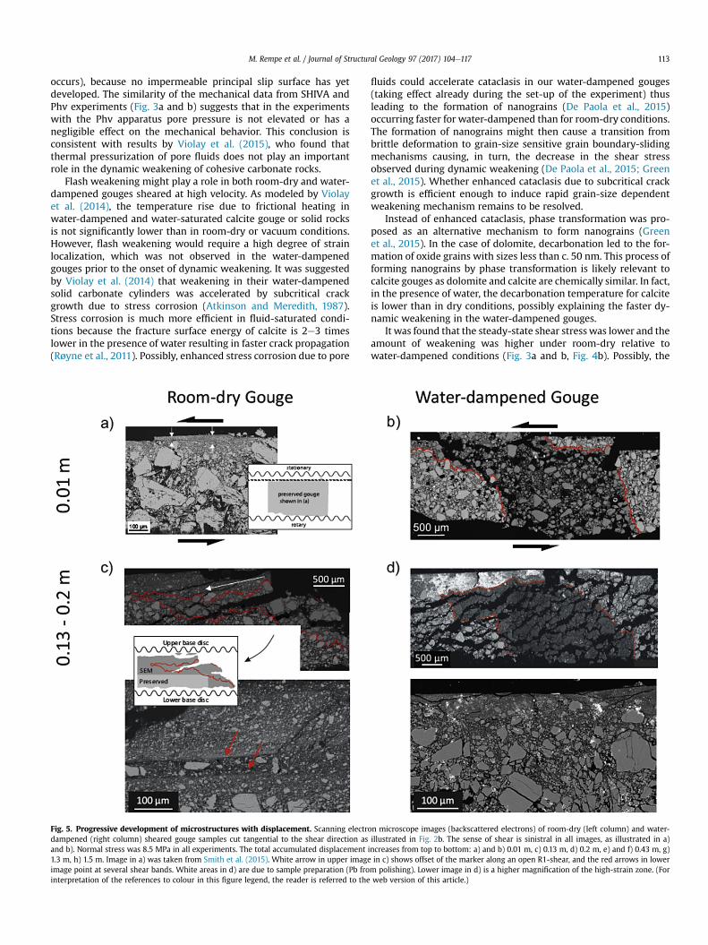
The microstructure of the sheared calcite gouges evolves withincreasing displacement, as previously described in dry calcitegouges by Bullock et al. (2015) and Smith et al. (2015) and in gougesof different lithologies (e.g., Oohashi et al., 2013). We were not ableto preserve a room-dry sample with a displacement of 0.01 mcontaining a strain marker due to its fragility after such short dis-placements. However, Smith et al. (2015) observed that after adisplacement of 0.01 m (prior to the onset of dynamic weakening),room-dry calcite gouges contain a well-defined, up to 20 mm thickshear band that developed close to the gouge layer boundary(Fig. 5a). The grains within the shear band were smaller in size andmore compacted than the surrounding material. Under the sameconditions as applied by Smith et al. (2015) in room-dry experi-ments (i.e., a total displacement of 0.01m, normal stress of 8.5 MPa,and a target velocity of 1 m/s), no such fine-grained, compactedshear bands were observed in water-dampened samples (s959,Table 1) (Fig. 5b). Instead, the particles are angular to sub-angular inshape and the porosity is high. Although no high-strain shear band
can be observed, the dolomite marker is inclined in the direction ofshearing due to an incipient boundary shear. The dolomite materialseems to have a slightly smaller grain size, indicating thatcomminution was at least starting to localize close to the uppersurface of the gouge layer.
At larger total displacements of 0.13e0.2 m, the zone ofcomminution has expanded into the gouge layer in both room-dryand water-dampened gouges (Fig. 5c and d). Larger particles, whichare still relatively angular and range from several tens of mmup to c.150 mm in size, are embedded in a fine-grained matrix with particlesizes on the order of a few tens of mm or less. The dolomite markeris sheared towards parallelism with the gouge layer boundaries. Inthe layer closest to the upper surface of the gouge layer, dolomitegrains are mixed with the fine-grained calcite that makes up thiszone. Additionally, several R-type shear bands (terminology afterLogan et al., 1979) developed in the room-dry sample, inclined at c.20� to gouge layer boundaries, accommodating some strain as isevidenced by an offset of the dolomite marker (Fig. 5c).
After a total displacement of 0.43 m, a discrete slip surfacedeveloped in both room-dry and water-dampened gouges (Fig. 5eand f). The slip surface cuts through a zone of highly-comminutedand -compacted gouge c. 125e600 mm thick. In this high-strainlayer many larger particles, generally several 10s of mm in size,are mixed in a matrix with a particle size of a few mms. Severalsecondary shear bands, generally oriented sub-parallel to the gougelayer boundary (Y-shears), may be found within the high-strainzone. The transition of the high-strain to the lower-strain zone,marked by the change in particle size and porosity, is rather abruptin both room-dry and water-dampened samples (Fig. 5e). After atotal displacement of 0.43 m in our water-dampened conditions(Fig. 5f), calcite grains adjacent to the principal slip surface, in azone 10e40 mm thick, have a relatively angular shape, with grainsizes in the order of 500 nm. They generally showa shape-preferredorientation with the long axis sub-parallel to the principal slipsurface consistent with the imposed sense of shear, resemblingmylonitic shear zones (e.g., Herwegh and Handy, 1998; Snoke et al.,1998). This appearance suggests recrystallization (Smith et al.,2013) and is consistent with the observations in room-dry gougesamples with a total displacement of 0.35 m by Smith et al. (2015).
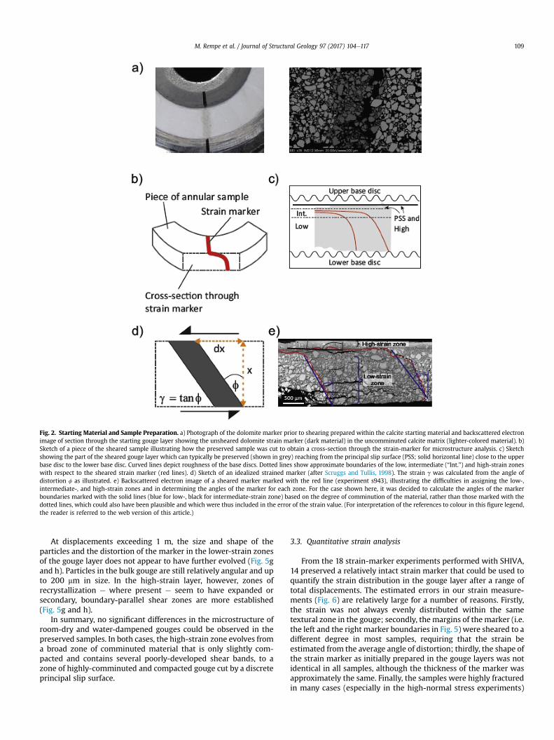
Fig. 2. Starting Material and Sample Preparation. a) Photograph of the dolomite marker prior to shearing prepared within the calcite starting material and backscattered electronimage of section through the starting gouge layer showing the unsheared dolomite strain marker (dark material) in the uncomminuted calcite matrix (lighter-colored material). b)Sketch of a piece of the sheared sample illustrating how the preserved sample was cut to obtain a cross-section through the strain-marker for microstructure analysis. c) Sketchshowing the part of the sheared gouge layer which can typically be preserved (shown in grey) reaching from the principal slip surface (PSS; solid horizontal line) close to the upperbase disc to the lower base disc. Curved lines depict roughness of the base discs. Dotted lines show approximate boundaries of the low, intermediate (“Int.”) and high-strain zoneswith respect to the sheared strain marker (red lines). d) Sketch of an idealized strained marker (after Scruggs and Tullis, 1998). The strain g was calculated from the angle ofdistortion f as illustrated. e) Backscattered electron image of a sheared marker marked with the red line (experiment s943), illustrating the difficulties in assigning the low-,intermediate-, and high-strain zones and in determining the angles of the marker for each zone. For the case shown here, it was decided to calculate the angles of the markerboundaries marked with the solid lines (blue for low-, black for intermediate-strain zone) based on the degree of comminution of the material, rather than those marked with thedotted lines, which could also have been plausible and which were thus included in the error of the strain value. (For interpretation of the references to colour in this figure legend,the reader is referred to the web version of this article.)
M. Rempe et al. / Journal of Structural Geology 97 (2017) 104e117 109
At displacements exceeding 1 m, the size and shape of theparticles and the distortion of the marker in the lower-strain zonesof the gouge layer does not appear to have further evolved (Fig. 5gand h). Particles in the bulk gouge are still relatively angular and upto 200 mm in size. In the high-strain layer, however, zones ofrecrystallization e where present e seem to have expanded orsecondary, boundary-parallel shear zones are more established(Fig. 5g and h).
In summary, no significant differences in the microstructure ofroom-dry and water-dampened gouges could be observed in thepreserved samples. In both cases, the high-strain zone evolves froma broad zone of comminuted material that is only slightly com-pacted and contains several poorly-developed shear bands, to azone of highly-comminuted and compacted gouge cut by a discreteprincipal slip surface.
3.3. Quantitative strain analysis
From the 18 strain-marker experiments performed with SHIVA,14 preserved a relatively intact strain marker that could be used toquantify the strain distribution in the gouge layer after a range oftotal displacements. The estimated errors in our strain measure-ments (Fig. 6) are relatively large for a number of reasons. Firstly,the strain was not always evenly distributed within the sametextural zone in the gouge; secondly, the margins of the marker (i.e.the left and the right marker boundaries in Fig. 5) were sheared to adifferent degree in most samples, requiring that the strain beestimated from the average angle of distortion; thirdly, the shape ofthe strain marker as initially prepared in the gouge layers was notidentical in all samples, although the thickness of the marker wasapproximately the same. Finally, the samples were highly fracturedin many cases (especially in the high-normal stress experiments)
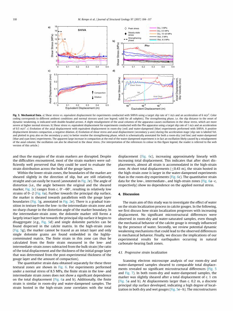
Fig. 3. Mechanical Data. a) Shear stress vs. equivalent displacement for experiments conducted with SHIVA using a target slip rate of 1 m/s and an acceleration of 6 m/s2. Colorcoding corresponds to different ambient conditions and normal stresses used (see legend, valid for all subplots). The strengthening phase, i.e. the slip distance to the onset ofdynamic weakening, is indicated with double-headed arrows. A slight misalignment of the axial columns of the apparatus causes oscillations in the shear stress, which are moresevere at higher normal stresses. b) Shear stress vs. equivalent displacement for experiments conducted with the Phv apparatus using a target slip rate of 1 m/s and an accelerationof 0.5 m/s2. c) Evolution of the axial displacement with equivalent displacement in room-dry (red) and water-dampened (blue) experiments performed with SHIVA. A positivedisplacement denotes compaction, a negative dilation. d) Evolution of shear stress and axial displacement (secondary y-axis) during the acceleration stage (slip rate is labeled Vel.and plotted in grey also on the secondary y-axis) to better resolve the strengthening phase, which is schematically annotated for both a room-dry (red line) and water-dampened(blue and cyan lines) experiments. The apparent large increase in compaction at the end of the water-dampened experiment is in fact an oscillation likely caused by a misalignmentof the axial column; the oscillation can also be observed in the shear stress. (For interpretation of the references to colour in this figure legend, the reader is referred to the webversion of this article.)
M. Rempe et al. / Journal of Structural Geology 97 (2017) 104e117110
and thus the margins of the strain markers are disrupted. Despitethe difficulties encountered, most of the strain markers were suf-ficiently well preserved that they could be used to evaluate thestrain distribution across the bulk of the gouge layers.
Within the lower-strain zones, the boundaries of the marker aresheared slightly in the direction of slip, but are still relativelystraight and can easily be traced (annotated in Fig. 2e). The angle ofdistortion (i.e., the angle between the original and the shearedmarker, Fig. 2c) ranges from c. 0�e60�, resulting in relatively lowstrains of 0e2 (Fig. 6a). Further towards the principal slip surface,the marker is sheared towards parallelism with the gouge layerboundaries (Fig. 5g, annotated in Fig. 2e). There is a gradual tran-sition in texture from the low- to the intermediate-strain zone andno sharp change in the distortion angle of the marker boundary. Inthe intermediate-strain zone, the dolomite marker still forms alargely intact layer but towards the principal slip surface it begins todisaggregate (e.g., Fig. 5d) and single dolomite particles can befound dispersed in the calcite matrix. In the high-strain zone(Fig. 5g), the marker cannot be traced as an intact layer and onlysingle dolomite grains are found embedded in the highly-comminuted matrix. The finite strain in this zone can thus becalculated from the finite strain measured in the low- andintermediate-strain zones subtracted from the bulk strain (the ratioof the total displacement and the thickness of the initial gouge layerthat was determined from the post-experimental thickness of thegouge layer and the amount of compaction).
The quantitative strain data obtained separately for these threetextural zones are shown in Fig. 6. For experiments performedunder a normal stress of 8.5 MPa, the finite strain in the low- andintermediate strain zones does not show a significant dependenceon the total displacement (Fig. 6a and b). Additionally, the finitestrain is similar in room-dry and water-dampened samples. Thestrain hosted in the high-strain zone correlates with the total
displacement (Fig. 6c), increasing approximately linearly withincreasing total displacement. This indicates that after short dis-placements, almost all strain is accommodated in the high-strainzone. At short total displacements (�0.43 m), the strain hosted inthe high-strain zone is larger in the water-dampened experimentsthan in the room-dry experiments (Fig. 6c). The quantitative straindata for the low-, intermediate-, and high-strain zones (Fig. 6aec,respectively) show no dependence on the applied normal stress.
4. Discussion
The main aim of this study was to investigate the effect of wateron the strain localization process in calcite gouges. In the following,we first discuss how strain localization progresses with increasingdisplacement. No significant microstructural differences wereobserved in room-dry and water-saturated samples, even thoughthe mechanical behavior of the calcite gouge is strongly influencedby the presence of water. Secondly, we review potential dynamicweakening mechanisms that could lead to the observed differencesin mechanical behavior. Finally, we discuss the implications of ourexperimental results for earthquakes occurring in naturalcarbonate-bearing fault zones.
4.1. Progressive strain localization
Scanning electron microscope analysis of our room-dry andwater-dampened samples sheared to comparable total displace-ments revealed no significant microstructural differences (Fig. 5and Fig. 7). In both room-dry and water-dampened samples, themarker was slightly sheared after a total displacement of c. 1 cm(Fig. 5a and b). At displacements larger than c. 0.2 m, a discreteprincipal slip surface developed, indicating a high degree of local-ization in both dry and wet gouges (Fig. 5eeh). The microstructures

Table 3Experimental results. Length of strengthening phase (dstrength), peak and steady state shear stress (tpeak and tss , respectively) with uncertainty ranges (min. and max. values)for a) room-dry and b) wet experiments.
Experiment dstrength(m)
dstrength,min
(m)dstrength,max
(m)tpeak(MPa)
tpeak,min
(MPa)tpeak,max
(MPa)tss(MPa)
tss,min
(MPa)tss,max
(MPa)
a) Room-dry s897 e e e 1.51 1.24 1.77 e e e
s886 0.78 0.48 0.80 2.29 2.15 2.39 1.44 1.20 1.57s953 e e e 5.14 5.05 5.23 e e e
s871 0.09 0.09 0.10 4.79 4.64 4.93 4.20 3.39 4.32s887 0.11 0.08 0.12 5.58 5.17 5.67 e e e
s881 0.09 0.06 0.09 5.27 4.74 5.32 3.06 2.43 3.70s1013 0.10 0.10 0.11 5.79 5.61 5.84 3.18 2.90 3.47s952 0.19 0.18 0.23 5.64 5.46 5.82 2.63 2.26 3.00s896 0.10 0.06 0.11 5.24 4.47 5.42 3.32 2.17 4.47s943 0.11 0.11 0.12 5.45 5.24 5.56 2.88 2.37 3.40s875 0.08 0.05 0.08 11.27 11.00 11.53 e e e
s889 0.03 0.03 0.04 14.50 14.31 14.68 5.38 4.84 5.91phv299 0.13 0.13 0.13 7.79 7.74 7.84 1.79 1.67 2.16phv301 0.15 0.14 0.15 7.85 7.77 7.89 1.54 1.12 2.07phv311 0.56 0.33 0.58 2.59 2.24 2.60 1.28 1.18 1.39phv343a 0.29 0.28 0.40 2.79 2.64 2.82 1.57 1.44 1.70
b) Water-dampened/-saturated s959 0.0055 0.0013 0.0060 4.81 4.47 5.36 e e e
s895 0.0015 0.0010 0.0043 4.62 4.37 4.96 3.69 3.53 3.92s961 0.0082 0.0038 0.0530 4.71 4.62 4.85 3.70 3.30 4.15s898 0.0030 0.0023 0.0638 4.87 4.53 5.39 3.77 3.32 4.21s962 0.0052 0.0014 0.0085 4.75 4.45 5.30 3.86 3.54 4.18s279 0.0058 0.0043 0.0074 11.49 10.94 11.69 4.36 3.70 5.02s389 0.0423 0.0378 0.0569 11.72 5.38 18.07 4.20 3.14 5.27phv291 0.0021 0.0017 0.0023 5.86 5.38 6.34 1.79 1.55 2.03phv292 0.0011 0.0006 0.0013 5.29 5.38 5.20 1.34 1.22 1.46phv297 0.0011 0.0011 0.0324 5.51 5.38 5.65 1.43 1.14 1.71phv298 0.0014 0.0013 0.0507 5.79 5.38 6.20 2.36 2.05 2.67phv300 0.0008 0.0006 0.0676 5.78 5.38 6.18 3.00 2.84 3.17phv312 0.0009 0.0007 0.0012 5.76 5.38 6.14 1.79 1.55 2.02phv306 0.0080 0.0066 0.0574 3.22 5.38 1.06 0.52 0.42 0.61phv310 0.0011 0.0009 0.0015 3.94 5.38 2.51 1.14 0.95 1.33phv307 0.0008 0.0007 0.0008 6.06 5.38 6.75 2.17 1.95 2.38phv309 0.0006 0.0006 0.0008 7.05 5.38 8.72 2.23 1.90 2.56phv304 0.0046 0.0035 0.0048 3.90 5.38 2.42 1.11 0.99 1.24phv305 0.0136 0.0130 0.0141 3.15 5.38 0.91 0.36 0.29 0.44phv340 0.0038 0.0036 0.0040 3.76 5.38 2.14 0.90 0.67 1.24phv350 0.0036 0.0036 0.0046 3.92 5.38 2.45 1.41 0.96 1.87phv290 0.0077 0.0077 0.0120 3.47 5.38 1.57 0.69 0.65 0.73phv337 0.0130 0.0109 0.0154 3.36 5.38 1.35 0.66 0.50 0.83phv355 0.0346 0.0047 0.0346 3.29 5.38 1.20 0.28 0.25 0.31phv351 0.0139 0.0038 0.0144 3.50 5.38 1.61 0.47 0.42 0.52phv313a 0.0066 0.0060 0.1754 3.86 5.38 2.34 1.31 1.12 1.50phv347a 0.0007 0.0006 0.0048 3.22 5.38 1.06 0.13 0.10 0.24
a Phv-experiments without pre-shearing.
M. Rempe et al. / Journal of Structural Geology 97 (2017) 104e117 111
suggest that strain localization progresses at a similar rate in room-dry and water-dampened gouges.
Likewise, the quantitative strain data obtained from the distor-tion of the strainmarkers do not showa significant difference in theamount of strain hosted in the low-, intermediate-, or high-strainzones of the room-dry and water-dampened samples. No cleardependence on the total displacement is evident in the lower-strainregions. The strain hosted in the high-strain zone, however, in-creases approximately linearly with total displacement (Fig. 6c)indicating that after localization is achieved most slip is hosted inthis principal slip zone independent of the ambient conditions.Thus, a substantial strain and velocity gradient is present betweenthe high- and the low-strain zones. This conclusion is supported bythe presence of recrystallized calcite grains (Fig. 5f) within a�40 mm wide zone adjacent to the principal slip surface of water-dampened samples, consistent with observations in dry calcitegouge (Smith et al., 2015), indicating a higher degree of frictionalheating close to the principal slip surface. Although most slip ishosted in the principal slip zone once localization is achieved,microstructural observations of Smith et al. (2015) showed that thegrain size in the bulk of the gouge layer continues to decrease,
suggesting at least some distributed deformation. Part of the strainin the bulk of the gouge layer is likely also accommodated on Y-, R1-and P-shears that are observed in many of our gouge samples.
The conclusion that the strain localization process is similar inroom-dry and water-dampened gouges seems to contrast with themechanical data showing a pronounced difference between ex-periments conducted in dry and wet conditions (Figs. 3, 4 and 7). Inour high-velocity calcite gouge experiments, dynamic weakeningoccurs much more abruptly in the presence of water (Fig. 3 andFig. 4a). The amount of water in the gouge layer appears to have aminor effect on the mechanical behavior, as gouges prepared withonly 20 wt% water (SHIVA experiments) behaved in a similarmanner to the completely saturated gouges deformed withcontrolled pore pressure (Phv experiments).
In previous studies, the initial strengthening phase observed inthe mechanical data has been attributed to progressive localizationof strain to a high-strain shear band that has to evolve to a criticalstate prior to weakening (e.g., by Marone et al., 1992; Beeler et al.,1996; Rathbun and Marone, 2010; Smith et al., 2015). Because thestrengthening phase was often accompanied by layer dilation,thought to be due to shear dilatancy during rolling and

Fig. 4. Dependence of strengthening phase and degree of weakening on thenormal stress. a) Length of the strengthening phase (i.e. the slip distance to the onsetof dynamic weakening) on a logarithmic scale and b) degree of weakening in room-dry(red symbols) and water-dampened (blue and black symbols) conditions vs. theapplied normal stress for experiments performed at a slip velocity of 1 m/s. Filledcircles indicate experiments performed with SHIVA, diamonds indicate data fromexperiments performed with the Phv apparatus, which is equipped with a controlledpore-fluid pressure system. Semi-filled diamonds indicate that the gouge was pre-sheared at 1 mm/s for 30 cm. Squares show data obtained by Smith et al. (2015) us-ing SHIVA. Where no error bars can be seen, the error is smaller than the data points.(For interpretation of the references to colour in this figure legend, the reader isreferred to the web version of this article.)
M. Rempe et al. / Journal of Structural Geology 97 (2017) 104e117112
comminution of particles (e.g., Mandl et al., 1977), it was concludedthat the strengthening phase is associated with some distributeddeformation rather than fully localized shear (Marone et al., 1990;Rathbun and Marone, 2010). In our experiments, no transientdilation was observed during or after the strengthening phase,possibly due to a different initial state of gouge compaction. Theobserved larger rate of compaction in the water-dampened gougescompared to the room-dry material prior to weakening (Fig. 3c)could be caused by some loss of water from the sample chamber. Itmight also suggest that the strain is in fact localizing faster inwater-dampened than in room-dry conditions, albeit to a small degreethat is not shown in the microstructures. In this case, the change inthe compaction ratewith the onset of dynamic weakening in room-
dry conditions (Fig. 3d) might likewise suggest a switch from ratherdistributed to more localized shear.
Based on their mechanical and microstructural data, Smith et al.(2015) concluded that localization of slip to a high-strain shearband is a necessary precursor to dynamic weakening in dry calcitegouges. In water-dampened gouges, however, as argued above,there is no microstructural evidence of strain localization to a high-strain shear band prior to (almost instantaneous) dynamic weak-ening (Fig. 5b and Fig. 7). Additionally, high-velocity friction ex-periments on solid Carrara marble cylinders (Violay et al., 2013),where slip is effectively localized from the beginning of theexperiment, also showed a much faster weakening in saturatedconditions, thus supporting the conclusion that it is not fasterlocalization causing the faster weakening in water-dampenedconditions. It follows that dynamic weakening in water-dampened gouges likely occurs prior to complete strain localiza-tion. Potential mechanisms that would lead to faster dynamicweakening in water-dampened conditions are discussed below(Section 4.2).
The close agreement of the shear stress evolution in room-dryand water-dampened conditions during the first ~8 mm of slip(Fig. 3d) gives rise to the idea that what we measure as strength-ening in water-dampened conditions might in fact be an apparentstrengthening induced by the stiffness of the apparatus. The stiff-ness of the columns of the apparatus should increase withincreasing normal load, thus leading to the observed decrease inthe apparent strengthening phase with increasing normal stress(Fig. 4a). The long strengthening phase in water-dampened con-ditions at normal stresses of 15 and 20 MPa may be due to loss ofwater during sample loading and compaction, or, quite to thecontrary, due to a thermal or mechanical pressurization of the porefluids, effectively decreasing the normal stress. In the room-dryconditions, the dependence on the normal stress is possibly dueto higher temperatures achieved in the slipping zone at highernormal stresses accelerating the onset of thermal weakeningmechanisms. The decrease in the length of the strengthening phasewith increasing normal stress is consistent with the results ob-tained by Smith et al. (2015) in room-dry conditions and thus withtheir conclusion that triggering of dynamic weakening in calcite-bearing fault zones is dependent on the normal stress, and largecoseismic slip may be impeded at shallow crustal depths due to aparticularly long strengthening phase (in addition to the stabilizingeffect of gouges present in a fault zone during the earthquakenucleation phase; Marone and Scholz, 1988).
4.2. Potential dynamic weakening mechanisms
The observed rapid dynamic weakening in water-dampenedconditions suggests that the active weakening mechanisms areeither more efficient or different from those acting in relatively dryconditions. In the following, we discuss possible weakeningmechanisms such as the formation of a fluid layer, thermal pres-surization, flash weakening, and the activation of grain-sizedependent mechanisms and evaluate their potential to accelerateweakening in the presence of fluids.
A simple explanation for the rapid weakening could be theformation of a lubricating water layer along one side of the gougelayer and/or the principal slip surface. However, this does notexplain the slightly higher steady state shear stress observed inwater-dampened conditions (Fig. 3a and b). Similarly, thermalpressurization of the pore fluid is not likely to accelerate weak-ening. Because water can escape from the holder, no excess porepressure can be maintained in the experiments with SHIVA.Expulsion of water from the gouge layer will occur readily in thefirst few centimeters of slip (i.e., when the dynamic weakening
M. Rempe et al. / Journal of Structural Geology 97 (2017) 104e117 113
occurs), because no impermeable principal slip surface has yetdeveloped. The similarity of the mechanical data from SHIVA andPhv experiments (Fig. 3a and b) suggests that in the experimentswith the Phv apparatus pore pressure is not elevated or has anegligible effect on the mechanical behavior. This conclusion isconsistent with results by Violay et al. (2015), who found thatthermal pressurization of pore fluids does not play an importantrole in the dynamic weakening of cohesive carbonate rocks.
Flash weakening might play a role in both room-dry and water-dampened gouges sheared at high velocity. As modeled by Violayet al. (2014), the temperature rise due to frictional heating inwater-dampened and water-saturated calcite gouge or solid rocksis not significantly lower than in room-dry or vacuum conditions.However, flash weakening would require a high degree of strainlocalization, which was not observed in the water-dampenedgouges prior to the onset of dynamic weakening. It was suggestedby Violay et al. (2014) that weakening in their water-dampenedsolid carbonate cylinders was accelerated by subcritical crackgrowth due to stress corrosion (Atkinson and Meredith, 1987).Stress corrosion is much more efficient in fluid-saturated condi-tions because the fracture surface energy of calcite is 2e3 timeslower in the presence of water resulting in faster crack propagation(Røyne et al., 2011). Possibly, enhanced stress corrosion due to pore
Fig. 5. Progressive development of microstructures with displacement. Scanning electrodampened (right column) sheared gouge samples cut tangential to the shear direction asand b). Normal stress was 8.5 MPa in all experiments. The total accumulated displacement i1.3 m, h) 1.5 m. Image in a) was taken from Smith et al. (2015). White arrow in upper imageimage point at several shear bands. White areas in d) are due to sample preparation (Pb frointerpretation of the references to colour in this figure legend, the reader is referred to the
fluids could accelerate cataclasis in our water-dampened gouges(taking effect already during the set-up of the experiment) thusleading to the formation of nanograins (De Paola et al., 2015)occurring faster for water-dampened than for room-dry conditions.The formation of nanograins might then cause a transition frombrittle deformation to grain-size sensitive grain boundary-slidingmechanisms causing, in turn, the decrease in the shear stressobserved during dynamic weakening (De Paola et al., 2015; Greenet al., 2015). Whether enhanced cataclasis due to subcritical crackgrowth is efficient enough to induce rapid grain-size dependentweakening mechanism remains to be resolved.
Instead of enhanced cataclasis, phase transformation was pro-posed as an alternative mechanism to form nanograins (Greenet al., 2015). In the case of dolomite, decarbonation led to the for-mation of oxide grains with sizes less than c. 50 nm. This process offorming nanograins by phase transformation is likely relevant tocalcite gouges as dolomite and calcite are chemically similar. In fact,in the presence of water, the decarbonation temperature for calciteis lower than in dry conditions, possibly explaining the faster dy-namic weakening in the water-dampened gouges.
It was found that the steady-state shear stresswas lower and theamount of weakening was higher under room-dry relative towater-dampened conditions (Fig. 3a and b, Fig. 4b). Possibly, the
n microscope images (backscattered electrons) of room-dry (left column) and water-illustrated in Fig. 2b. The sense of shear is sinistral in all images, as illustrated in a)ncreases from top to bottom: a) and b) 0.01 m, c) 0.13 m, d) 0.2 m, e) and f) 0.43 m, g)in c) shows offset of the marker along an open R1-shear, and the red arrows in lowerm polishing). Lower image in d) is a higher magnification of the high-strain zone. (Forweb version of this article.)

Fig. 5. Continued
M. Rempe et al. / Journal of Structural Geology 97 (2017) 104e117114
steady-state stress and the amount of weakening is also controlledby crystal-plastic deformation processes such as grain boundarysliding aided by diffusion creep. Due to the grain-size dependenceof diffusion creep in carbonate rocks (Schmid et al., 1977), a slightlysmaller grain size in room-dry conditions might be responsible forthe lower steady-state shear stress (assuming similar diffusionrates). Microstructural evidence for crystal-plastic deformationprocesses is provided by recrystallized grains lining the principalslip surface (Fig. 5f). However, to identify whether nanograins arepresent on the slip surfaces of our samples and if the grain size isdifferent in the room-dry and water-dampened sheared gouges,higher-resolution microstructural work needs to be carried out.
4.3. Implications for natural faults
In nature, frictional sliding on a pre-existing fault will initiate if acritical shear stress due to tectonic loading is reached, potentiallyleading to dynamic weakening of the fault, i.e., an earthquakeinstability. Velocity-strengthening behavior of the fault rocks mightlead to an arrest of rupture prior to catastrophic failure. In ourrotary-shear gouge experiments, simulating frictional sliding on apre-existing fault, such a potentially stabilizing strengtheningphase is observed under room-dry conditions. In the water-dampened and saturated experiments the strengthening phase
was significantly shorter, implying that at shallow depths, gouge-bearing faults in carbonates will be more prone to rapid dynamicweakening in the presence of water. Violay et al. (2013) reached asimilar conclusion for solid (cohesive) samples of carbonate. Fasterweakening in wet conditions occurs if only a relatively smallamount of water (only 20 wt% H2O were used in our water-dampened experiments with SHIVA, Fig. 3a) is present and also ifthe fault contains pressurized fluids. This has important implica-tions for the coseismic rupture behavior of faults. As suggested byour experimental results (Fig. 3 and Fig. 4a), dynamic weakeningwill occur faster if water is present in the slip zones. Local evidenceof the involvement of water during faulting was indeed found byseveral studies of carbonate-bearing faults (De Paola et al., 2008;Collettini et al., 2009; Smith et al., 2011). Additionally, an hetero-geneous distribution of fluids in a fault zone might explain some ofthe slip distribution complexity observed during earthquake se-quences in carbonate (Cirella et al., 2009; Pino and Di Luccio, 2009;Di Stefano et al., 2011). For instance, the heterogeneous coseismicslip distribution of the 2009 Mw6.3 L'Aquila mainshock correlateswell with the near-fault pattern of aftershocks that cluster aroundthe high-slip patches (Cirella et al., 2009) and that were attributedto the presence of high-pressure fluids at depth (Chiodini et al.,2011; Miller, 2013).

Fig. 6. Strain distribution in the gouge layer. Quantitative strain data as obtained from measurement of the angle of distortion of the sheared marker vs. the total equivalentdisplacement of the respective sample. The strain was determined separately for a) the low-strain zone, b) the intermediate-strain zone and c) the high-strain zone.
M. Rempe et al. / Journal of Structural Geology 97 (2017) 104e117 115
5. Conclusion
A series of intermediate- to high-velocity rotary-shear experi-ments was conducted on synthetic calcite gouges prepared withdolomite strain markers. The strain marker experiments wereconducted with varying total displacements (0.011e2.5 m), normalstresses (3e21 MPa) and ambient conditions (room-dry and water-dampened) to study strain-localization processes and to test thedependence of the strain distribution on these different experi-mental variables.
The mechanical behavior of room-dry and water-dampened
gouges sheared at 1 m/s is significantly different: while theroom-dry gouges show a prolonged strengthening phase prior todynamic weakening, the water-dampened gouges dynamicallyweaken nearly instantaneously to a steady-state shear stress that isslightly higher than in room-dry conditions. Microstructural anal-ysis of the sheared dolomite markers revealed progressive strainlocalization to a thin (125e600 mm) high-strain layer that devel-oped after several cm of slip in both room-dry and water-saturatedconditions. The strain hosted in the bulk of the gouge layer did notchange significantly with increasing total displacement suggestingthat, once formed, the high-strain slipping zone and slip surface

Fig. 7. Schematic summary of the mechanical and microstructural evolution of dry and wet calcite gouges sheared at high velocity. Phase 1) Strengthening of the gouges;development of a low-strain shear band. Phase 2) Strengthening of the dry and abrupt dynamic weakening of the wet gouges; similar microstructures marked by development of ahigh-strain shear band and R1 shears. Phase 3) Both dry and wet gouges weakened to a steady-state shear stress; discrete slip surfaces within zone of heating.
M. Rempe et al. / Journal of Structural Geology 97 (2017) 104e117116
accommodated most of the subsequent displacement and that asubstantial strain and velocity gradient exists in the thin layer ofgouge. No significant differences in the degree or timing of strainlocalization were observed in room-dry and water-dampenedgouges, leading to the conclusion that faster dynamic weakeningin water-dampened conditions is not because of faster localizationbut due to a different or more efficient weakening mechanism thanin room-dry conditions. The faster dynamic weakening in thepresence of fluids might explain some of the observed slip distri-bution complexity in natural carbonate-bearing fault zones.
Acknowledgements
Andrea Cavallo, Rolf Neuser and Leonardo Tauro are thanked forassistance with SEM analysis. Elena Spagnuolo, Fabio Ferri andKentaro Hatakeda are thanked for technical assistance. This workwas supported by Ca.Ri.Pa.Ro.; a 2014 University of Otago ResearchGrant; the Marsden Fund Council (project UOO1417), administeredby the Royal Society of New Zealand; the European ResearchCouncil Starting Grant USEMS [grant no. 205175], the EuropeanResearch Council Consolidator Grant NOFEAR [grant no. 614705]and the JSPS KAKENHI [grant no. 16H04064]. Anne Pluymakers andan anonymous reviewer are thanked for valuable suggestions thathelped to improve this manuscript.
References
Aben, F., Doan, M.L., et al., 2016. Dynamic fracturing by successive coseismic load-ings leads to pulverization in active fault zones. J. Geophys. Res. Solid Earth 121(4), 2338e2360.
Atkinson, B.K., Meredith, P.G., 1987. The theory of subcritical crack growth withapplications to minerals and rocks. Fract. Mech. Rock 2, 111e166.
Beeler, N., Tullis, T., et al., 1996. Frictional behavior of large displacement experi-mental faults. J. Geophys. Res. Solid Earth (1978e2012) 101 (B4), 8697e8715.
Ben-Zion, Y., Sammis, C.G., 2003. Characterization of fault zones. Pure Appl. Geo-phys. 160 (3e4), 677e715.
Boullier, A.M., Yeh, E.C., et al., 2009. Microscale anatomy of the 1999 Chi-Chiearthquake fault zone. Geochem. Geophys. Geosyst. 10.
Bullock, R.J., De Paola, N., et al., 2015. An experimental investigation into the role ofphyllosilicate content on earthquake propagation during seismic slip in car-bonate faults. J. Geophys. Res. Solid Earth 120 (5), 3187e3207.
Chester, F.M., Chester, J.S., 1998. Ultracataclasite structure and friction processes ofthe Punchbowl fault, San Andreas system, California. Tectonophysics 295 (1),199e221.
Chester, F.M., Evans, J.P., et al., 1993. Internal structure and weakening mechanismsof the San-andreas fault. J. Geophys. Res. Solid Earth 98 (B1), 771e786.
Chiodini, G., Caliro, S., et al., 2011. Geochemical evidence for and characterization ofCO 2 rich gas sources in the epicentral area of the Abruzzo 2009 earthquakes.Earth Planet. Sci. Lett. 304 (3), 389e398.
Cirella, A., Piatanesi, A., et al., 2009. Rupture history of the 2009 L'Aquila (Italy)
earthquake from non-linear joint inversion of strong motion and GPS data.Geophys. Res. Lett. 36 (19).
Collettini, C., De Paola, N., et al., 2009. Insights on the geometry and mechanics ofthe UmbriaeMarche earthquakes (Central Italy) from the integration of fieldand laboratory data. Tectonophysics 476 (1), 99e109.
De Paola, N., Agosta, F., et al., 2012. Constraints on fault dynamic weakeningmechanisms from natural slip surfaces in carbonate faults. In: AGU Fall MeetingAbstracts.
De Paola, N., Collettini, C., et al., 2008. Fault zone architecture and deformationprocesses within evaporitic rocks in the upper crust. Tectonics 27 (4).
De Paola, N., Hirose, T., et al., 2011. Fault lubrication and earthquake propagation inthermally unstable rocks. Geology 39 (1), 35e38.
De Paola, N., Holdsworth, R.E., et al., 2015. Can grain size sensitive flow lubricatefaults during the initial stages of earthquake propagation? Earth Planet. Sci.Lett. 431, 48e58.
Di Stefano, R., Chiarabba, C., et al., 2011. Fault zone properties affecting the ruptureevolution of the 2009 (Mw 6.1) L'Aquila earthquake (central Italy): insightsfrom seismic tomography. Geophys. Res. Lett. 38 (10).
Di Toro, G., Niemeijer, A., et al., 2010. From field geology to earthquake simulation: anew state-of-the-art tool to investigate rock friction during the seismic cycle(SHIVA). Rendiconti lincei 21 (1), 95e114.
Faulkner, D., Mitchell, T., et al., 2011. Stuck in the mud? Earthquake nucleation andpropagation through accretionary forearcs. Geophys. Res. Lett. 38 (18).
Fondriest, M., Smith, S.A., et al., 2012. Fault zone structure and seismic slip locali-zation in dolostones, an example from the Southern Alps, Italy. J. Struct. Geol.45, 52e67.
Fondriest, M., Smith, S.A.F., et al., 2013. Mirror-like faults and power dissipationduring earthquakes. Geology 41 (11), 1175e1178.
Goldsby, D.L., Tullis, T.E., 2011. Flash heating leads to low frictional strength ofcrustal rocks at earthquake slip rates. Science 334 (6053), 216e218.
Green, H., Shi, F., et al., 2015. Phase transformation and nanometric flow causeextreme weakening during fault slip. Nat. Geosci. 8 (6), 484e489.
Han, R., Hirose, T., 2012. Clay-clast aggregates in fault gouge: an unequivocal in-dicator of seismic faulting at shallow depths? J. Struct. Geol. 43, 92e99.
Han, R., Hirose, T., et al., 2010. Strong velocity weakening and powder lubrication ofsimulated carbonate faults at seismic slip rates. J. Geophys. Res. Solid Earth 115(B3).
Han, R., Shimamoto, T., et al., 2007. Ultralow friction of carbonate faults caused bythermal decomposition. Science 316 (5826), 878e881.
Heermance, R., Shipton, Z.K., et al., 2003. Fault structure control on fault slip andground motion during the 1999 rupture of the Chelungpu fault, Taiwan. Bull.Seismol. Soc. Am. 93 (3), 1034e1050.
Herwegh, M., Handy, M., 1998. The origin of shape preferred orientations inmylonite: inferences from in-situ experiments on polycrystalline norcamphor.J. Struct. Geol. 20 (6), 681e694.
Hirose, T., Shimamoto, T., 2005. Growth of molten zone as a mechanism of slipweakening of simulated faults in gabbro during frictional melting. J. Geophys.Res. Solid Earth 110 (B5).
Kitajima, H., Chester, J.S., et al., 2010. High-speed friction of disaggregated ultra-cataclasite in rotary shear: characterization of frictional heating, mechanicalbehavior, and microstructure evolution. J. Geophys. Res. Solid Earth 115.
Kohli, A.H., Goldsby, D.L., et al., 2011. Flash weakening of serpentinite at near-seismic slip rates. J. Geophys. Res. Solid Earth 116 (B3).
Lachenbruch, A.H., 1980. Frictional heating, fluid pressure, and the resistance tofault motion. J. Geophys. Res. Solid Earth 85 (B11), 6097e6112.
Logan, J., Friedman, M., et al., 1979. Experimental studies of simulated gouge andtheir application to studies of natural fault zones. U. S. Geol. Surv. Open File Rep.1978, 305e343.

M. Rempe et al. / Journal of Structural Geology 97 (2017) 104e117 117
Mandl, G., De Jong, L., et al., 1977. Shear zones in granular material. Rock Mech. 9(2e3), 95e144.
Marone, C., Hobbs, B., et al., 1992. Coulomb constitutive laws for friction: contrastsin frictional behavior for distributed and localized shear. Pure Appl. Geophys.139 (2), 195e214.
Marone, C., Raleigh, C.B., et al., 1990. Frictional behavior and constitutive modelingof simulated fault gouge. J. Geophys. Res. Solid Earth 95 (B5), 7007e7025.
Marone, C., Scholz, C., 1988. The depth of seismic faulting and the upper transitionfrom stable to unstable slip regimes. Geophys. Res. Lett. 15 (6), 621e624.
Miller, S.A., 2013. The role of fluids in tectonic and earthquake processes. Adv.Geophys. 54, 1e46.
Morrow, C., Moore, D.E., et al., 2000. The effect of mineral bond strength andadsorbed water on fault gouge frictional strength. Geophys. Res. Lett. 27 (6),815e818.
Niemeijer, A., Di Toro, G., et al., 2011. Frictional melting of gabbro under extremeexperimental conditions of normal stress, acceleration, and sliding velocity.J. Geophys. Res. Solid Earth 116 (B7).
Oohashi, K., Hirose, T., et al., 2013. Graphite as a lubricating agent in fault zones: aninsight from low-to high-velocity friction experiments on a mixed graphite-quartz gouge. J. Geophys. Res. Solid Earth 118 (5), 2067e2084.
Pavlis, T.L., Serpa, L.F., et al., 1993. Role of seismogenic processes in fault-rockdevelopment: an example from Death Valley, California. Geology 21 (3),267e270.
Pino, N.A., Di Luccio, F., 2009. Source complexity of the 6 April 2009 L'Aquila(central Italy) earthquake and its strongest aftershock revealed by elementaryseismological analysis. Geophys. Res. Lett. 36 (23).
Platt, J.D., Rudnicki, J.W., et al., 2014. Stability and localization of rapid shear in fluid-saturated fault gouge: 2. Localized zone width and strength evolution.J. Geophys. Res. Solid Earth 119 (5), 4334e4359.
Proctor, B., Mitchell, T., et al., 2014. Dynamic weakening of serpentinite gouges andbare surfaces at seismic slip rates. J. Geophys. Res. Solid Earth 119 (11),8107e8131.
Rathbun, A.P., Marone, C., 2010. Effect of strain localization on frictional behavior ofsheared granular materials. J. Geophys. Res. Solid Earth 115 (B1).
Rempel, A.W., Rice, J.R., 2006. Thermal pressurization and onset of melting in faultzones. J. Geophys. Res. Solid Earth (1978e2012) 111 (B9).
Rockwell, T.K., Ben-Zion, Y., 2007. High localization of primary slip zones in largeearthquakes from paleoseismic trenches: observations and implications forearthquake physics. J. Geophys. Res. Solid Earth 112 (B10).
Rowe, C.D., Fagereng, Å., et al., 2012. Signature of coseismic decarbonation indolomitic fault rocks of the Naukluft Thrust, Namibia. Earth Planet. Sci. Lett.333e334, 200e210.
Røyne, A., Bisschop, J., et al., 2011. Experimental investigation of surface energy andsubcritical crack growth in calcite. J. Geophys. Res. Solid Earth 116 (B4).
Sawai, M., Shimamoto, T., et al., 2012. Reduction in BET surface area of Nojima faultgouge with seismic slip and its implication for the fracture energy of earth-quakes. J. Struct. Geol. 38, 117e138.
Schmid, S., Boland, J., et al., 1977. Superplastic flow in finegrained limestone. Tec-tonophysics 43 (3), 257e291.
Scruggs, V., Tullis, T., 1998. Correlation between velocity dependence of friction andstrain localization in large displacement experiments on feldspar, muscovite
and biotite gouge. Tectonophysics 295 (1), 15e40.Sibson, R.H., 1986. Brecciation processes in fault zones: inferences from earthquake
rupturing. Pure Appl. Geophys. 124 (1e2), 159e175.Sibson, R.H., 2003. “Thickness of the seismic slip zone. Bull. Seismol. Soc. Am. 93 (3),
1169e1178.Siman-Tov, S., Aharonov, E., et al., 2013. Nanograins form carbonate fault mirrors.
Geology 41 (6), 703e706.Smith, S., Nielsen, S., et al., 2015. Strain localization and the onset of dynamic
weakening in calcite fault gouge. Earth Planet. Sci. Lett. 413, 25e36.Smith, S.A.F., Billi, A., et al., 2011. Principal slip zones in limestone: microstructural
characterization and implications for the seismic cycle (Tre Monti fault, centralApennines, Italy). Pure Appl. Geophys. 168 (12), 2365e2393.
Smith, S.A.F., Di Toro, G., et al., 2013. Coseismic recrystallization during shallowearthquake slip. Geology 41 (1), 63e66.
Snoke, A.W., Tullis, J., et al., 1998. Fault-related Rocks: A Photographic Atlas.Princeton University Press.
Tadai, O., Tanikawa, W., et al., 2009. Design of new frictional testing machine forshallow fault materials. In: AGU Fall Meeting Abstracts.
Tanikawa, W., Mukoyoshi, H., et al., 2012. Experimental investigation of the influ-ence of slip velocity and temperature on permeability during and after high-velocity fault slip. J. Struct. Geol. 38, 90e101.
Togo, T., Shimamoto, T., 2012. Energy partition for grain crushing in quartz gougeduring subseismic to seismic fault motion: an experimental study. J. Struct.Geol. 38, 139e155.
Ujiie, K., Tsutsumi, A., 2010. High-velocity frictional properties of clay-rich faultgouge in a megasplay fault zone, Nankai subduction zone. Geophys. Res. Lett.37.
Verberne, B., Spiers, C., et al., 2014a. Frictional properties and microstructure ofcalcite-rich fault gouges sheared at sub-seismic sliding velocities. Pure Appl.Geophys. 171 (10), 2617e2640.
Verberne, B.A., de Bresser, J.H., et al., 2013. Nanocrystalline slip zones in calcite faultgouge show intense crystallographic preferred orientation: crystal plasticity atsub-seismic slip rates at 18e150� C. Geology 41 (8), 863e866.
Verberne, B.A., He, C., et al., 2010. Frictional properties of sedimentary rocks andnatural fault gouge from the Longmen Shan fault zone, Sichuan, China. Bull.Seismol. Soc. Am. 100 (5B), 2767e2790.
Verberne, B.A., Plümper, O., et al., 2014b. Superplastic nanofibrous slip zones controlseismogenic fault friction. Science 346 (6215), 1342e1344.
Violay, M., Di Toro, G., et al., 2015. Thermo-mechanical pressurization of experi-mental faults in cohesive rocks during seismic slip. Earth Planet. Sci. Lett. 429,1e10.
Violay, M., Nielsen, S., et al., 2014. Effect of water on the frictional behavior ofcohesive rocks during earthquakes. Geology 42 (1), 27e30.
Violay, M., Nielsen, S., et al., 2013. Pore fluid in experimental calcite-bearing faults:abrupt weakening and geochemical signature of co-seismic processes. EarthPlanet. Sci. Lett. 361, 74e84.
Yao, L., Shimamoto, T., et al., 2013. Rapid postseismic strength recovery of Pingxifault gouge from the Longmenshan fault system: experiments and implicationsfor the mechanisms of high-velocity weakening of faults. J. Geophys. Res. SolidEarth 118 (8), 4547e4563.