journal: przeglad elektrotechniczny -...
TRANSCRIPT

2010 JCR Science Edition
Journal: Przeglad Elektrotechniczny
Mark Journal Title ISSN Total CitesImpactFactor
5-YearImpactFactor
ImmediacyIndex
CitableItems
CitedHalf-life
CitingHalf-life
PRZ ELEKTROTECHNICZN 0033-2097 617 0.242 0.043 1058 2.7 8.0
Cited Journal Citing Journal Source Data Journal Self Cites
Journal Information Full Journal Title: Przeglad Elektrotechniczny
EigenfactorTM MetricsEigenfactorTM Score0.00050
Article InfluenceTM
Score
ISO Abbrev. Title: Prz. ElektrotechnicznyJCR Abbrev. Title: PRZ ELEKTROTECHNICZN
ISSN: 0033-2097Issues/Year: 12
Language: POLISHJournal Country/Territory: POLAND
Publisher: WYDAWNICTWO SIGMA-N O T SP Z O OPublisher Address: UL RATUSZOWA 11, PO BOX 1004, 00-950
WARSAW, POLANDSubject Categories: ENGINEERING, ELECTRICAL & ELECTRONIC
Journal Rank in Categories:
Journal Impact Factor
Cites in 2010 to items published in: 2009 =134 Number of items published in: 2009 =647 2008 =178 2008 =640 Sum: 312 Sum: 1287 Calculation:Cites to recent items 312 = 0.242 Number of recent items 1287
5-Year Journal Impact Factor
Cites in {2010} to items published in: 2009 = 134 Number of items published in: 2009 =647 2008 = 178 2008 =640 2007 = 71 2007 =359 2006 = 43 2006 =0 2005 = 17 2005 =0 Sum: 443 Sum: 1646 Calculation:Cites to recent items 443 = Number of recent items 1646
Journal Self Cites The tables show the contribution of the journal's self cites to its impact factor. This information is also represented in
JCR-Web 4.5 Journal Information http://admin-apps.webofknowledge.com/JCR/JCR?RQ=RECORD&ran...
1 of 3 ق.ظ 08:30 2012/03/04
240 PRZEGLĄD ELEKTROTECHNICZNY (Electrical Review), ISSN 0033-2097, R. 88 NR 3b/2012
PRZEGLĄD ELEKTROTECHNICZNY (Electrical Review) Vol 2012, No 3b
Contents
01 Yucheng LIU, Yubin LIU - A New Image Enhancement Based on the Fuzzy C-Means Clustering 1 02 Xianmin LI, Yuan ZHANG - Experiment Study on JS125-6A EFI Motorcycle for European Emission Regulatio 5 03 Yulin GONG, Yongyin QU - Novel Adaptive Inverse Control for Permanent Magnet Synchronous Motor Servo
System 9
04 Suyun LUO, Yuanming GONG, Xinping SONG - Phases PID Controller of Common-rail Pressure for Diesel Engine Electronic Injector Test Bench
15
05 Jianbin ZOU, Kai GAO, Eryang ZHANG - Research on Angle Measurement Model of Anti-radiation Missiles PRS under Coherent Decoys
18
06 Wenhao CAI, Hui REN - Research on Grid-Connected Photovoltaic System Based on Improved Algorithm 22 07 Guang DONG, Weili SHI, Jing LIU, Yinlong HU - Research on the Intercommunication of Healthy Records
and Hospital Medical Records 26
08 Weili SHI, Yanfang LI, Yu MIAO, Yinlong HU - Research on the Key Technology of Image Guided Surgery 29 09 Zhumu FU, Leipo LIU, Aiyun GAO, Jiexin PU - Robust Dynamic Output Feedback H Control for
Uncertain Switched Singular Systems 34
10 Jianguo SHENG, Cancan ZHANG, Ping ZENG - Study of the Nanotechnology in Manufacture of Generators 39 11 Xiaoyu ZHU, Xiaojiu LI, Bokun SUN - Study on electromagnetic shielding efficacy of knitting clothing 42 12 Xianmin LI,Xi LU, Guangde HAN - The Design and Simulation Research of Mazda6 Hybrid Electric Vehicle 44 13 Xiaoyan ZHANG, Jingqiu CHEN, Yongxiang ZHANG, Chunxia WEI - Numerical Simulation of ESWL with
Single-pulse and Dual-pulse Based on 2D Unstructured Grid CE/SE Method 48
14 Kai SUN, Weng Chio LAI - Integrated Passenger Service System for Ideal Process Flow in Airports 54 15 Hua LI, Jian ZHANG, Da XU, Meng-chun ZHONG - Design on Neural Network Controller of Engine-
generator for Electro-thermal gun in the tracked Vehicle 60
16 Tong ZHANG, Kehe WU, Gang MA, Wei LI - A Network Business Security Model Based on Developed BLP Model in Electric Power Enterprise
63
17 Gang MA, Kehe WU,Tong ZHANG, Wei LI - A Flexible Policy-Based Access Control Model for Workflow 67 18 Zhaowen YAN, Yansheng WANG, Mingming CHE, Yajing HAN, Tao WANG, Toyobur RAHMAN - A Novel
Design of Electromagnetic Bandgap Structure and its Effects on PI and SI 72
19 Xiaohui KUANG, Gang ZHAO, Yong TANG, Jin LI - Structural Vulnerability Analysis for Large-Scale Distributed System based on Multi-layer Topology Model
78
20 Juan WANG, Guokia XU, Haiying DU - Robust H output feedback control for constrained discrete-time piecewise affine systems with time-parametric uncertainties
84
21 RuiYang YUAN - Resonant spin transport through a double quantum-dot system with ferromagnetic electrodes and tunable magnetic field
88
22 Yun WANG - The research for the auxiliary power unit APU and its work characteristics of BJD6100HEV series hybrid electric bus
93
23 Tao ZHANG, Yan-qiu CUI, Juan WANG, Ran-feng ZHANG - New delay-dependent stability for systems with interval time-varying delay
97
24 Xiaojie LIU - An immune based model for dynamic intrusion detection 10025 Yongming HUANG, Guobao ZHANG, Fei DONG, Yue LI, Feipeng DA - Speech Emotion Recognition Using
Hybrid Generative and Discriminative Models 105
26 Yuyan JIANG, Hao SUN, Ping LI, Zheng WANG, Zhuting ZHANG - Synergy E-business-Based Control Mode of Perception Mechanism
109
27 Mohammad H. MORADI, Younes MOHAMMADI, Mina HOSEYNI TAYYEBI - A novel method to locate the voltage sag source: a case study in the Brazilian power network (Mato Grosso)
112
28 Mahmoud A. YOUNIS , Tamer KHATIB, Mushtaq NAJEEB, A Mohd ARIFFIN - An Improved Maximum Power Point Tracking Controller for PV Systems Using Artificial Neural Network
116
29 Sofiane MENDACI, Mohamed Rachid MEKIDECHE, Ali REZIG - Analytical Calculation of Magnetic Field in Surface-Mounted Permanent Magnet Motors Taking Into Account Slotting Effect
122
30 Seyed Mohammad SHARIATMADAR, Jalal NAZARZADEH, Mehrdad ABEDI - Non-linear Analytical Extended Poincare's Model of Phase Saturated Self Excited Series Connected Synchronous Generators
126
31 Dechang YANG, Christian REHTANZ, Yong LI, Qianjin LIU, Kay GÖRNER - Denoising and detrending of measured oscillatory signal in power system
135
32 Lin XU, Yang HAN - Passivity-based Controller Design and Stable Control Region Analysis of the Cascaded DSTATCOM
140
33 Qing LI, Gehao SHENG, Yadong LIU, Wubing QIU, Kaisui CAI, Xingquan HUANG, Xiuchen JIANG - Research of the GIS Structure Influence on Propagation Characteristic of Partial Discharge Electromagnetic Waves
149
34 Yongchun LIANG, Jing ZHAO, Yun DU, Jianhua ZHANG - An Optimal Heat Line Simulation Method to Calculate the Steady-Stage Temperature and Ampacity of Buried Cables
156
35 Yunfeng XIA, Xingliang JIANG, Caixin SUN, Bingbing Dong - A Method to Estimate Leakage Current of Polluted Insulators
161

PRZEGLĄD ELEKTROTECHNICZNY (Electrical Review) Vol 2012, No 3b
Contents
36 Omid SHARIFI-TEHRANI - Hardware Design of Image Channel Denoiser for FPGA Embedded Systems 16537 Zahra NASIRI-GHEDARI, Hamid LESANI - Design Optimization of a Single-Phase Axial Flux Induction Motor
with Low Torque Ripple 168
38 Rachid TALEB, Abdelkader MEROUFEL, Ahmed MASSOUM - Control of a Uniform Step Asymmetrical Multilevel Inverter using Particle Swarm Optimization
173
39 Kai HAN, Muqing LIU, Shenglong FAN, Haiping SHEN - Improved Electrical Measurement Method for Junction Temperature of Light Emitting Diodes
180
40 Abbas SHIRI, Abbas SHOULAIE - Multi-objective optimal design of low-speed linear induction motor using genetic algorithm
185
41 Slami SAADI, Abderrezak GUESSOUM, Maamar BETTAYEB - Regularized Total Variation Image Enhancement Using E.Coli Bacteria Foraging Algorithm: Application to Neutron Radiography Projections
192
42 Mahammad Abdul HANNAN, Farid Arafat AZIDIN, Azah MOHAMED - Light Vehicle Energy Management System using Multi-Power Sources
197
43 Ahmed MASSOUM, Abdelkader MEROUFEL, Abderrahim BENTAALLAH - Sliding Mode Speed Controller for a Vector Controlled Double Star Induction Motor
205
44 Reza MALEKIAN, Abdul Hanan ABDULLAH - Bidirectional and RO Methods for Analysis of Stream-Intensive Applications over Mobile IP Network
210
45 Wei SUN, Gengxin ZHANG, Xiao JIE, Liang GOU - NCPIE: network-coding-based cooperative peer-to-peer information exchange in wireless communications
214
46 Shahram JAMALI, Hekmat MOHAMMADZADEH - SODMRP: Stable On-Demand Multicast Routing Protocol
219
47 Muhammad Faisal SIDDIQI, Muhammad Kamran BHATTI, Sana SHUJA, Shaista JABEEN, Azhar YASEEN,Abid Ali MINHAS5, Shahzad A. MALIK, Shahid A. KHAN, Raja Ali RIAZ - ASIC Design Implementation of Memory Efficient Infinite Impulse Response UWB Equalizer
223
48 Arash ASRARI, Dawood Seyed JAVAN, Mohammad Hossein JAVIDI, Mohammad MONFARED -Application of Gray-Fuzzy-Markov Chain Method for Day-Ahead Electric Load Forecasting
228
126 PRZEGLĄD ELEKTROTECHNICZNY (Electrical Review), ISSN 0033-2097, R. 88 NR 3b/2012
Seyed Mohammad SHARIATMADAR1, Jalal NAZARZADEH2, Mehrdad ABEDI3
Science and Research Branch, Islamic Azad University (1), Shahed University (2), Amir-Kabir University of Technology (3)
Non-linear Analytical Extended Poincare's Model of Phase Saturated Self Excited Series Connected Synchronous
Generators
Abstract. In the present paper, first a magnetization current base model is introduced for the electrical machine analyzing that saturation is occurred for the phase that its current entered to saturation region. Other part of machine may be saturated or in the linear condition in order of their currents. Then a new analytical extended Poincare's map is introduced for modelling of self excited series connected synchronous generators in saturated conditions. Using the non-linear control theory, an analytical first order Poincare's map of the machines is computed. Then extended Poincare's map of the machine is introduced. After that characteristic multipliers of the self excited series connected synchronous generator are determined. Non-linearity of the machine can be modelled with the new map and stability analysis of the system is investigated. The new map is capable for modelling, control, bifurcation and chaos analysis in the non-linear (saturation) conditions. Finally the simulation results of the new extended Poincare's map with experimental laboratory set-up results are compared. The results show that the new Poincare's map is an effective method for modelling and analysis of any ac electrical machines. Streszczenie: Wprowadzono model prądu magnesującego maszyny elektrycznej w rejonie nasycenia do analizy stanu nasycenia samowzbudnych generatorów synchronicznych. Wykorzystano model Poincare. Zamodelowano nieliniowość maszyny i obliczono warunki stabilności. Rezultaty symulacji pokazują że zaproponowany model może być wykorzystany do analizy różnych maszyn elektrycznych AC. (Nieliniowy analityczny model samowzbudnych połączonych szeregowo generatorów synchronicznych) Keywords: Chaos, Poincare's Map, Self Excited Series Connected Synchronous Generators, Saturation. Słowa kluczowe: samowzbudny generator synchroniczny, mapa Poincare, nasycenie. Introduction Self excited ac generators are suitable machines for wind energy conversion. Induction, reluctance and permanent magnetic generators are representative of such applications. Self Excited Induction Generator (SEIG) was one of earliest types of self excited ac generators. It has the advantages of brush-less construction with squirrel cage rotor, reduced size, absence of dc power supply for excitation, reduced maintenance cost and better transient characteristics [1, 2, 3]. SEIG will have a serious problem in voltage regulation when load or speed changes. Both the magnitude and frequency of produced voltage of a SEIG are affected by the dynamic of loads. Connected Synchronous Generator (SESCSG) has some advantages over SEIG and acts as a hypothetical salient pole machine. It operates at half the rotor angular frequency which is independent of loading conditions [4]. Mustafa et al. [5, 6] investigated the steady-state performances of three-phase SESCSG by considering saturation effects using the dq model. Transient and steady state performance analysis of SESCSG can be applied with the generalized theory and the dq reference frame [7]. Effects of sudden disconnection of one excitation capacitor on the output voltages in the abc frame was investigated [4]. Wang et. al. continued the research about various kinds of induction generators for some years until [8]. Self excitation phenomena and load performance are investigated with two-dimensional finite element analysis in [9]. Their method, however, is not suitable for non-linear problems such as chaos identification. Most of the papers have studied the SESCSG in the steady-state conditions and considered improving the machine performance. Dynamic analysis and voltage building process in the dq frame have been presented in the few papers but generally speaking, the dq model is not able to analyze SESCSG in the non-linear and unbalanced conditions. Thus, sudden disconnection or variation excitation capacitor of one phase can be analyzed with abc frame modelling method. Output signals of the machine are periodic and time variant. Consequently, which accordingly linearization of the system could not be carried out in the whole period of the system. Jacobian’s matrix of the system
could only be derived in the single operating point of the output and all of the system performance in the whole period could not be shown. Also, the Poincare’s map for analysis of the periodic systems is recommended [10]. The Poincare’s map model for time varying systems such as buck and boost dc-dc converters was obtained [11, 12]. Stability and dynamic analysis of the proposed system are investigated with the control considerations. Non-linear phenomena such as intermittent bifurcations and chaos in boost converters under peak-current control mode were modelled by the Poincare’s map [13]. Two non-linear models in the form of discrete maps were derived to describe precisely the non-linear dynamics of boost converters from the two perspectives: low and high frequency regimes. Although the Poincare’s map is a powerful method in the nonlinear control theory, it is not suitable for the system with time variant output signal (sinusoidal output). Modified Poincare’s map (higher order Poincare’s map) appears to be a candidate in such cases [11]. This map is the result of n sequential conventional Poincare’s maps in which the character of each operating point of the system in the whole period the system, is scanned and gathered in the final modified Poincare’s map. In almost all of previous works, dc to dc converters were investigated by the Poincare’s map. For a system with ac output, such as ac variable active passive reactance system, the modified Poincare’s map was also used in order to improving of chaos phenomena by optimal control approach [14, 15]. In this paper, a novel model based on magnetizing current is initially introduced which is capable of investigating saturation in each phase of the machine. Through the use of this modelling a part of machine saturated whose currents entered the saturation region and other phases are not practically saturated. A new extended Poincare’s map model for electrical machines is then devised by using the non-linear control theory. The dynamical periodic system can be linearized around the map on the selected plane in the orbit of the system by deriving the extended Poincare’s map. This map is an effective method for modelling and analysis of the machine in saturation and unbalance conditions. Through the characteristic multipliers of the
PRZEGLĄD ELEKTROTECHNICZNY (Electrical Review), ISSN 0033-2097, R. 88 NR 3b/2012 127
linearized extended Poincare’s map, stability, chaos and bifurcation of the system can be analyzed. In order to evaluate the method, a couple of laboratory test results in which the efficiency of the new model is demonstrated. Mathematical model of the system Dynamical model of SESCSG Stator and rotor voltage equations of a saturated induction machine are:
(1)
( ) ( ) ( ) ( )
( ) ( ) ( ) ( )
s s s ls s s
r r r lr r r
d dt t t t
dt dtd d
t t t tdt dt
� � �
� � �
V R i L i Λ
V R i L i Λ
where sR , rR , lsL and lrL are resistance and leakage inductance diagonal matrices of the rotor and stator windings which have rs , rr , lls and llr in their diagonal elements, respectively. The vectors ( )s tV , ( )r tV , ( )s ti
and ( )r ti represent the voltage and current of stator and
rotor windings, respectively. Also, ( )s tΛ and ( )r tΛ are flux linkage vectors of stator and rotor windings, which can be further expressed by matrix form as the following:
(2) � �
� �( ) ( ) ( ) ( )
( ) ( ) ( ) ( )
Tas bs cs
Tar br cr
t t t t
t t t t
� � �
� � �
�
�s
r
Λ
Λ
Using the chain rule for derivation in Eq. (2), we can write:
(3)
( ) ( )( )( ) ( )( )( )( ) ( )( )
( ) ( )( )( ) ( )( )( )( ) ( )( )
as mas
mas
bs mbs
mbs
cs mcs
mcs
ar mar
mar
br mbr
mbr
cr mcr
mcr
d t di tdi t dtd t di td t
dt di t dtd t di tdi t dt
d t di tdi t dtd t di td t
dt di t dtd t di tdi t dt
� �
� � �� �
� � �
�
�
�
�
�
�
s
r
Λ
Λ
where ( )masi t to ( )mcri t are the magnetization currents of stator and rotor windings, respectively. According to the electrical circuits approach, magnetization reactance of each phase is the slope of its magnetization flux to the corresponding magnetization current. Obviously, in the linear system this slope is constant. Thus we have:
(4)
( )( ) , ,
( )j
m mjmj
d tL i j as rc
di t� � rc,
�
where ( )m mL i is magnetization reactance i.e. the slope of
mi � in the saturation curve. Substituting Eq. (4) into Eq. (3), we have:
(5) ( ) ( ) ( )
( ) ( ) ( )
ms ms m
mr mr m
d dt tdt dtd dt tdt dt
�
�
s s
r r
Λ L i i
Λ L i i
where
(6)
� �� �
( ) ( ) ( ) ( )( ) ( ) ( ) ( )
ms ms m mas m mbs m mcs
mr mr m mar m mbr m mcr
diag L i L i L idiag L i L i L i��
L iL i
and
(7) ( ) ( ( ) ( ) ( ))
( ) ( ( ) ( ) ( ))
Tms mas mbs mcs
Tmr mar mbr mcr
t i t i t i t
t i t i t i t
�
�
i
i
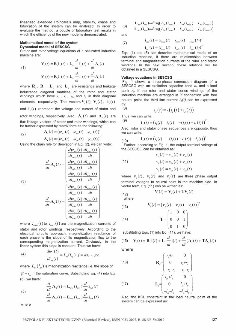
Eqs. (1) and (5) can describe mathematical model of an induction machine, if there are relationships between terminal and magnetization currents of the rotor and stator windings. In the next section, these relations will be obtained in a SESCSG. Voltage equations in SESCSG Fig. 1 shows a three-phase connection diagram of a SESCSG with an excitation capacitor bank co and a load bank ro. If the rotor and stator series windings of the induction machine are arranged in Y connection with free neutral point, the third line current i3(t) can be expressed by: (8) � � � � � �� �3 1 2i t = - i t + i t
Thus, we can write: (9) � �1 2 1 2( ) ( ) ( ) ( ( ) ( )) T
s t i t i t i t i t� �i Also, rotor and stator phase sequences are opposite, thus we can write:
(10) � �1 1 2 2( ) ( ) ( ( ) ( )) ( ) T
r t i t i t i t i t� �i
Further, according to Fig. 1, the output terminal voltage of the SESCSG can be obtained as:
(11)
( ) ( ) ( )( ) ( ) ( )( ) ( ) ( )
a as ar
b bs cr
c cs br
v t v t v tv t v t v tv t v t v t
� �
� �
� �
where ( )av t , ( )bv t and ( )cv t are three phase output terminal voltages to neutral point in the machine side. In vector form, Eq. (11) can be written as:
(12)
( ) ( ) ( )t s rt t t� �V V TV
where
(13) � �( ) ( ) ( ) ( ) Tt a b ct v t v t v t�V
(14)
1 0 00 0 10 1 0
�� � � �
T
substituting Eqs. (1) into Eq. (11), we have:
(15) ( ) ( ) ( ) ( ( ) ( ))t c l r
d dt t t t t
dt dt� � � �sV R i L i Λ TΛ
where
(16)
00
s r
c s r
s r s r
r rr r
r r r r
�
� �
� � � �
R
(17)
00
ls lr
l ls lr
ls lr ls lr
l ll l
l l l l
�
� �
� � � �
L
Also, the KCL constraint in the load neutral point of the system can be expressed as:
128 PRZEGLĄD ELEKTROTECHNICZNY (Electrical Review), ISSN 0033-2097, R. 88 NR 3b/2012
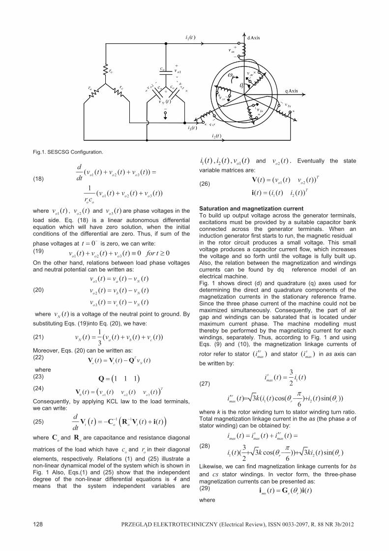
Fig.1. SESCSG Configuration.
(18) 1 2 3
1 2 3
( ( ) ( ) ( ))
1( ( ) ( ) ( ))
o o o
o o oo o
dv t v t v t
dt
v t v t v tr c
� � �
� �
where 1( )ov t , 2 ( )ov t and 3 ( )ov t are phase voltages in the load side. Eq. (18) is a linear autonomous differential equation which will have zero solution, when the initial conditions of the differential are zero. Thus, if sum of the
phase voltages at 0t � is zero, we can write: (19)
1 2 3( ) ( ) ( ) 0 0o o ov t v t v t for t� � � � On the other hand, relations between load phase voltages and neutral potential can be written as:
(20) 1
2
3
( ) ( ) ( )( ) ( ) ( )( ) ( ) ( )
o a N
o b N
o c N
v t v t v tv t v t v tv t v t v t
�
�
�
where ( )Nv t is a voltage of the neutral point to ground. By substituting Eqs. (19)into Eq. (20), we have:
(21)
1( ) ( ( ) ( ) ( ))
3N a b cv t v t v t v t� � �
Moreover, Eqs. (20) can be written as: (22) ( ) ( ) ( )T
o t Nt t v t� V V Q where (23) � �1 1 1�Q (24) � �0 1 2 3( ) ( ) ( ) ( ) T
o o ot v t v t v t�V Consequently, by applying KCL law to the load terminals, we can write:
(25) � � � �1 1 ( ) ( )t o o t
dt t t
dt � �V C R V i
where oC and oR are capacitance and resistance diagonal
matrices of the load which have oc and or in their diagonal elements, respectively. Relations (1) and (25) illustrate a non-linear dynamical model of the system which is shown in Fig. 1 Also, Eqs.(1) and (25) show that the independent degree of the non-linear differential equations is 4 and means that the system independent variables are
1( )i t , 2 ( )i t , 1( )ov t and 2 ( )ov t . Eventually the state variable matrices are:
(26) 1 2
1 2
( ) ( ( ) ( ))
( ) ( ( ) ( ))
To o
T
t v t v t
t i t i t
�
�
V
i
Saturation and magnetization current To build up output voltage across the generator terminals, excitations must be provided by a suitable capacitor bank connected across the generator terminals. When an induction generator first starts to run, the magnetic residual in the rotor circuit produces a small voltage. This small voltage produces a capacitor current flow, which increases the voltage and so forth until the voltage is fully built up. Also, the relation between the magnetization and windings currents can be found by dq reference model of an electrical machine. Fig. 1 shows direct (d) and quadrature (q) axes used for determining the direct and quadrature components of the magnetization currents in the stationary reference frame. Since the three phase current of the machine could not be maximized simultaneously. Consequently, the part of air gap and windings can be saturated that is located under maximum current phase. The machine modelling must thereby be performed by the magnetizing current for each windings, separately. Thus, according to Fig. 1 and using Eqs. (9) and (10), the magnetization linkage currents of
rotor refer to stator ( )rmasi� and stator ( )s
masi in as axis can be written by:
(27) 1
1 2
3( ) ( )
2
( ) 3 ( ( )cos( ) ( )sin( ))6
smas
rmas r r
i t i t
i t k i t i t
�
� � ��
� �
where k is the rotor winding turn to stator winding turn ratio. Total magnetization linkage current in the as (the phase a of stator winding) can be obtained by:
(28) 1 2
( ) ( ) ( )
3( )( 3 cos( )) 3 ( )sin( )
2 6
s rmas mas mas
r r
i t i t i t
i t k ki t
�� � �
� ��
� �
Likewise, we can find magnetization linkage currents for bs and cs stator windings. In vector form, the three-phase magnetization currents can be presented as: (29) ( ) ( ) ( )ms s rt t� �i G i where
PRZEGLĄD ELEKTROTECHNICZNY (Electrical Review), ISSN 0033-2097, R. 88 NR 3b/2012 129
(30)
33 cos( ) 3 sin( )
2 63
( ) 3 cos( ) 3 ( )6 2 6
3 33 ( ) 3 cos( )
2 2 6
r r
s r r r
r r
k k
k kcos
ksin k
�
� �
� �
� � � �
�� �
� �� � �
�� �
G
Similarly, vector form of rotor magnetization current based on terminal currents of machines 1 ( )i t and 2 ( )i t can be expressed as: (31) ( ) ( ) ( )mr r rt t� �i G i where
(32)
3 3 3cos( ) sin( )
2 63 3 3 3
( ) sin( ) cos( )2 2 6
3 3 3( ) cos( )
6 2 6
r r
r r r r
r r
k k
k k
cosk k
�
� � �
�
� � � �
�� �
�� � �
� �� �
G
According to Eq. (5), the partial derivation of the phase magnetization currents must be constructed. Also, regarding Eqs. (29) and (31), the rotor and stator magnetization current vectors are depended on the 1 ( )i t , 2 ( )i t and
( )r t� .Therefore, partial derivation of the phase magnetization currents for the rotor and stator windings is:
(33)
1 2
1 2
1 2
1 2
( )
( )
ms ms ms rms
r
mr mr mr rmr
r
i idt
dt i t i t t
i idt
dt i t i t t
� � �� � �� � �� � � � � �
� � �� � �� � �� � � � � �
��
��
i i ii
i i ii
Eqs. (33) represent the partial derivations of two magnetization current vectors ( )ms ti and ( )mr ti subject to a
scalar functions 1 ( )i t , 2 ( )i t and ( )r t� .Thus, by using Eqs. (31) and (29), we can rearrange Eqs. (33) to matrix form as:
(34)
( ) ( ) ( ) ( ( )) ( )
( ) ( ) ( ) ( ( )) ( )
rms s r s r
r
rmr r r r r
r
d dt t t
dt dt t
d dt t t
dt dt t
� �� �
� �
� �� �
� �
�� �
�
�� �
�
i G i G i
i G i G i
Using partial derivations of ( )s r�G and ( )r r�G in Eqs. (30) and (32), we can obtain matrix coefficient in Eq. (34). Substituting Eqs. (34), (5) into (15), the voltage equations of a SESCSG in state space form can be constructed as:
(35) ( ) ( , ) ( ) ( , ) ( )t t t
dt t
dt� �V R i t i t L i t i
where
(36)
1( , ) ( ) [ ( )
3
( ) ( ) ( )]
T rt c ms ms
s r mr mr r rr r
tt
�� � �
�� �
�� �
�
� �� �
R i R I Q Q L i
G TL i G
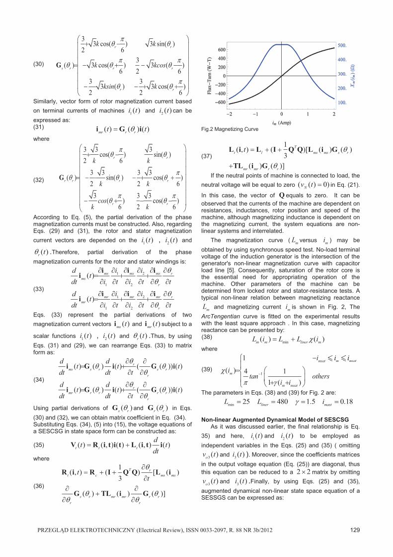
Fig.2 Magnetizing Curve
(37)
1( , ) ( )[ ( ) ( )
3( ) ( )]
Tt l ms ms s r
mr mr r r
t � � �
�
�
�
L i L I Q Q L i G
TL i G
If the neutral points of machine is connected to load, the neutral voltage will be equal to zero ( ( ) 0)Nv t � in Eq. (21).
In this case, the vector of Q equals to zero. It can be observed that the currents of the machine are dependent on resistances, inductances, rotor position and speed of the machine, although magnetizing inductance is dependent on the magnetizing current, the system equations are non-linear systems and interrelated.
The magnetization curve ( mL versus mi ) may be obtained by using synchronous speed test. No-load terminal voltage of the induction generator is the intersection of the generator's non-linear magnetization curve with capacitor load line [5]. Consequently, saturation of the rotor core is the essential need for appropriating operation of the machine. Other parameters of the machine can be determined from locked rotor and stator-resistance tests. A typical non-linear relation between magnetizing reactance
mL and magnetizing current mi is shown in Fig. 2, The ArcTengentian curve is fitted on the experimental results with the least square approach . In this case, magnetizing reactance can be presented by: (38)
min( ) ( )m m liner mL i L L i� � � where
(39) 1
1
( ) 4 11 ( )
msat m msat
m
m msat
i i i
itan others
i i
�
� �
��
� �� � � ��
�
� �
m msati i
The parameters in Eqs. (38) and (39) for Fig. 2 are:
min 25 480 1.5 0.18liner mastL L i� � � ��
Non-linear Augmented Dynamical Model of SESCSG
As it was discussed earlier, the final relationship is Eq. 35) and here, 1 ( )i t and 2 ( )i t to be employed as independent variables in the Eqs. (25) and (35) ( omitting
3 ( )ov t and 3 ( )i t ). Moreover, since the coefficients matrices in the output voltage equation (Eq. (25)) are diagonal, thus this equation can be reduced to a 2 2� matrix by omitting
3 ( )ov t and 3 ( )i t .Finally, by using Eqs. (25) and (35), augmented dynamical non-linear state space equation of a SESSGS can be expressed as:
130 PRZEGLĄD ELEKTROTECHNICZNY (Electrical Review), ISSN 0033-2097, R. 88 NR 3b/2012
(40) ( ) ( ( ), ) ( )
dt t t t
dt�X A X X
where
(41) � �( ) ( ) ( )TT Tt t t�X i V
(42)
1 1
1 1 1
( , ) ( , ) ( , )( ( ), )
o o o
t t tt t
�
� � � �
L i R i L iA X
C C R
( , )tR i and ( , )tL i are 2 2� reduced matrices in Eqs. (36) and (37). Finally, complexity of equations and the wide range variation of output variables cause the system not to have an operating point, thereby the system outputs are large sinusoidal periodic and cannot be linearized by conventional method such as small signal analysis approach. In the following a Poincare's map which is an effective technique for periodic systems, will be introduced. Poincare's map in periodic systems The Poincare's map is a standard method from dynamical systems theory to study the dynamics of periodic systems [16]. The main idea of this approach is to observe the system state once per cycle. Consider a non-linear dynamical periodic system as:
(43) � �( ) ( ),
dt t t
dt�X A X
where � �( ),t tA X is an n system vector with a fixed
period T (i.e. � � � �( ), ( ),t T t T t t� � �A X A X ). By
applying a dummy variable ( )r t� to Eq.(43), we have:
(44) � �( ) ( ), ( )
2( )
r
r
dt t t
dtd
tdt T
�
�
�
��
X A X
Eqs.(44) presents a ( 1) ( 1)n n� � � autonomous
dynamical system with period T . In this system, we can find a n n� open space V with a close sub-space S in it
(V S� ) so that any system states ( )tX and ( )r t� in V
transverse to S in time close to T. The sub-vector space S may be selected as:
(45) � ��
�
1 1 1
0 0
( ), ( ) ( ) , ( ) ,
( ) ,0 2
nr r
r
S t t t t
t
� �� �� ��
�
� �
� � � �
X X
A Poincare's map P for the dynamical system (Eq. (43)) can be defined as:
(46)
� � � �0 0
:
( ), ( ),a
V S
t t
!
" ���� (� (��� �
P
X X
where � �0( ),a t" �X is a transition matrix of the system which can be determined by numerical methods in non-linear cases. Eq. (46) can be restated as: (47) � � � �0( ) ( ), ( )t T t t� � ��X X P X
� �0( ),t" �X is a sub-set of � �0( ),a t" �X . If we call the
system state collision to V at time t as kX , the Poincare's map of the system (stroboscopic map) in Eq.(47) can be written as: (48)
1 ( )k k� �X P X
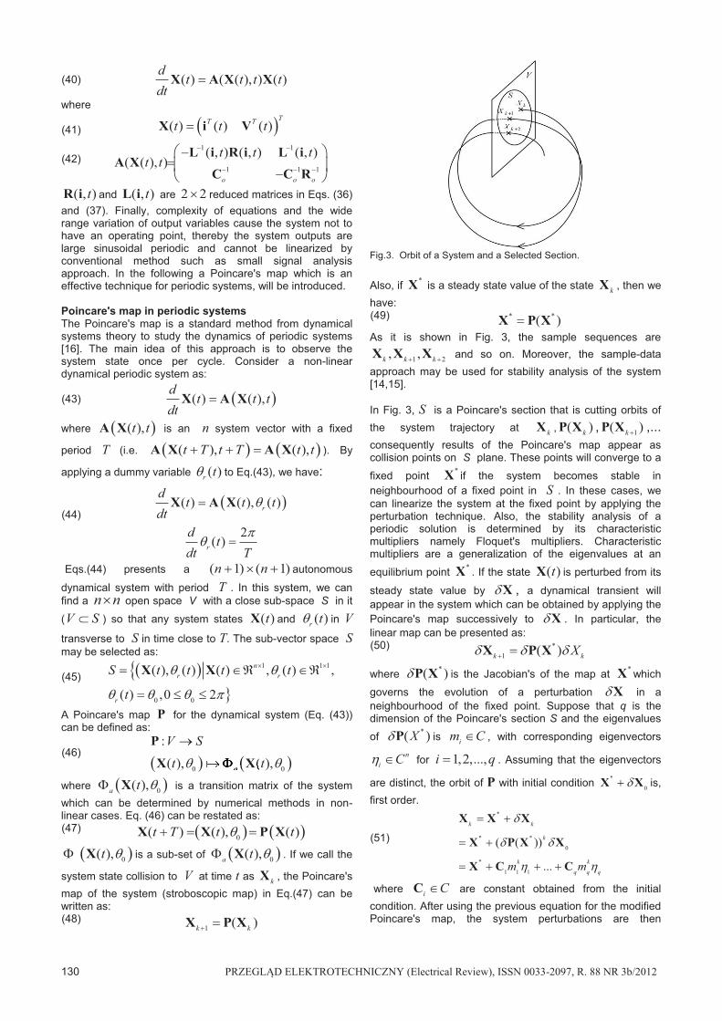
Fig.3. Orbit of a System and a Selected Section.
Also, if *X is a steady state value of the state kX , then we have: (49) * *( )�X P X As it is shown in Fig. 3, the sample sequences are
1 2, ,k k k� �X X X and so on. Moreover, the sample-data approach may be used for stability analysis of the system [14,15]. In Fig. 3, S is a Poincare's section that is cutting orbits of the system trajectory at kX , ( )kP X , 1( )k�P X ,... consequently results of the Poincare's map appear as collision points on S plane. These points will converge to a
fixed point *X if the system becomes stable in neighbourhood of a fixed point in S . In these cases, we can linearize the system at the fixed point by applying the perturbation technique. Also, the stability analysis of a periodic solution is determined by its characteristic multipliers namely Floquet's multipliers. Characteristic multipliers are a generalization of the eigenvalues at an
equilibrium point *X . If the state ( )tX is perturbed from its
steady state value by #X , a dynamical transient will appear in the system which can be obtained by applying the Poincare's map successively to #X . In particular, the linear map can be presented as: (50) *
1 ( )k kX� �# # #X P X
where *( )#P X is the Jacobian's of the map at *X which governs the evolution of a perturbation #X in a neighbourhood of the fixed point. Suppose that q is the dimension of the Poincare's section S and the eigenvalues of *( )X#P is im C� , with corresponding eigenvectors
ni C�$ for 1,2,...,i q� . Assuming that the eigenvectors
are distinct, the orbit of P with initial condition *
0� #X X is, first order.
(51)
*
* *
0
*
1 1 1
( ( ))
...
k k
k
k k
q q qm m
� �
� �
� � � �
#
# #
$ $
X X X
X P X X
X C C
where i C�C are constant obtained from the initial condition. After using the previous equation for the modified Poincare's map, the system perturbations are then
PRZEGLĄD ELEKTROTECHNICZNY (Electrical Review), ISSN 0033-2097, R. 88 NR 3b/2012 131
investigated for the whole period and the Jacobian matrix can be found. As a result the multipliers describe the conditions of the system. Finally it must be considered that the Poincare's map works in the discrete space and the system have to be converted to discrete model [10]. Non-linearity terms of the system do not permit us to use conventional methods accordingly, a method will be introduced in the next section.
Poincare's map of SESCSG
As mentioned in the previous section section, in order to derive a Poincare's map for the system, trajectory of the system must be found. A conventional method is integration from state space equations of the machine above the whole period of the system [10]. The conventional integration method proved to be incapable and the trapezoidal integration method is thus proposed. Trapezoidal method in the electrical machines analysis is a well known idea. It is the base of the phase domain method [17]. For the purpose of solving the machine's electrical quantities in the time domain, the state space equations are changed into discrete form with the trapezoidal rule of integration. Discrete format of equations is common in the phase domain method and the Poincare's map method. By applying trapezoidal integration rule to Eq. (40), we can find:
(52)
� �
( ) ( ( ), ) .2
( ), ( )2
tt t t t t t
tt t t
%� % � � % � %
%�
� � � �� � � �
1
X I A X
I A X X
where I is a 4 4� identity matrix. Also, according to the saturation function in Eq. (38), the inductances of the machine are dependent on winding currents and vice versa. Consequently, the right hand side of Eq. (52) has elements which depend on the system state at t t� % and are not compatible with the Poincare's map defined in Eq. (48). In order to overcoming this problem and to find recursive Poincare's map of the machine, we can predict the state of the systems by the Euler method [18] as: (53) � �ˆ ( ) ( ( ), ) ( )t t t t t t� % � � %X I A X X
If in the right hand side of the Eq. (52) , ( )t t� %X is
replaced by ˆ ( )t t� %X in Eq. (53), the recursive relation for determining the state variables of the system will be become independent system state at t t� % . Thus, we have: (54) � �( ) ( ), ( )t t t t t� % �"X X X where
(55)
� �
� �
1
ˆ( ), ( ( ), ) .2
( ),2
tt t t t t t
tt t
%" � � % � %
%�
� � � �� � � �
X I A X
I A X
The recursive map of Eq. (54) will have a proper result, when the step of integration ( t% ) is selected very smaller than period of system. Thus similar to Eq. (54) and with t=kT and T m t� % , the relationship between
( )t n t� %X and ( ( 1) )t n t� %X can be presented:
(56)
1 1(( ) ) (( ) ),( ) .
1(( ) )
n n nk T k T k T
m m mn
k Tm
� �" � �
�
� � � �
X X
X
According to Eq. (56), we have to obtain a time invariant recursive map for state variables. For this purpose, if the SESCSG operates in a constant speed, we can identify a relation between r� and t . In this case, we can write
0r rt� �� & � and time sequences , , 2 ,t t t t t� % � %
and t n t� % can replace by 0 , � 0
2 ,
m�
�� ,
0
2
nm
��
� . Thus, by substituting r� with t in Eq. (56), a
recursive map for state variable form ( 1)t n t� % to t n t� % can be expressed as:
(57)
1 0 1
2( 1),n n n
k k km m m
nT
� � �
� " �
� � � �
��X X X
where nk
m�
X is state vector of system at t n t� % .
Comparing Eqs. (57) with (48), the Poincare's map of the system can be expressed as:
(58)
� �
0
1 1 01
2( 1),k n k
kn m m
k k
nT�
��
� " �
�
� �� �
� �� �' �
�X X X
P X X
Thus, the final discrete map changes the problem of analyzing the stability of the orbit into one of the stability of a fixed point. After each t% , all state variables of the saturated machine are calculated according to the previous state variables. Unbalance and unsymmetrical systems (with initial condition assumption) with deep non-linearity can be modelled by the use of this method. Chaos and bifurcation of the system can be recognized and controlled. As mentioned characteristic multipliers position in the complex plane determines the stability of the system. Absolute values of the characteristic multipliers show the system stability condition like stability, bifurcation, chaos and instability.
Case Study
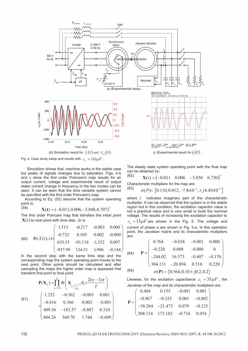
An experimental set-up has been prepared for simulation results validation. The test system consists of a wounded rotor induction machine whose parameters are given in the table I. In Fig. 4-a, a synchronous motor is shown which is coupled with the induction machine in which an advanced inverter, is used to supply the synchronous motor, magnitude and frequency of the synchronous motor are adjusted by the inverter. The inverter output voltage and frequency ratio must be kept constant throughout the test.
t% is selected equal to 0.6283 msec small enough to cover all signal phenomena. In order to simplify the voltage building at nominal network frequency with small excitation capacitor the generator-motor set is provided which operates as a motor with SW1 switch by opening SW1, it acts as a generator. For first experimental test conditions, the machine is connected to 1600or � ( with excitation
capacitor C0 = 10 )F.
132 PRZEGLĄD ELEKTROTECHNICZNY (Electrical Review), ISSN 0033-2097, R. 88 NR 3b/2012
(a )Experimental setup.
(b) Simulation result for 1 ( )i t and 1( )ov t . (c )Experimental result for 1( )i t . Fig. 4. Case study setup and results with 10oc F� ) .
Simulation shows that, machine works in the stable case
but peaks of signals changes due to saturation. Figs. 4-b and c show the first order Poincare's map results for an output current, voltage and experimental result of output stator current change in frequency in the two modes can be seen. It can be seen that the time variable system cannot be specified with the first order Poincare's map.
According to Eq. (52) assume that the system operating point is: (59) ( ) ( 0.011,0.006, 3.848,6.707)T� X t The first order Poincare map that transfers the initial point
( )tX to next point with time step t% is:
(60)
1.513 -0.217 -0.003 0.000-0.732 0.105 0.002 -0.000
( ( ), )635.55 -91.118 -1.352 0.097-937.99 134.51 1.996 -0.144
X t t" �
� � � �
In the second step with the same time step and the corresponding map the system operating point moves to the next point. Other points should be calculated and after cascading the maps the higher order map is appeared that transfers first point to final point.
(61)
0
1 0576 576
2( 1)( ) ,
1.252 0.562 0.003 0.0010.816 0.366 0.002 0.001
409.36 183.57 0.887 0.310804.26 360.70 1.744 0.609
k nkn
nT
��
� " �
�
� � � �
� � � �
' ��P X X
The steady state system operating point with the final map can be obtained by: (62) � �( ) 0.011 0.006 3.850 6.730 Tt � X Characteristic multipliers for the map are: (63) � �6 6( ) 0.110,0.012, 7.8 10 , 4.45 10 P j � � * �+
where j indicates imaginary part of the characteristic multiplier. It can be observed that the system is in the stable region but in this condition, the excitation capacitor value is not a practical value and is very small to build the nominal voltage. The results of increasing the excitation capacitor to
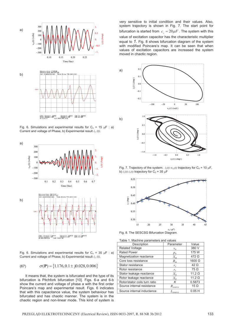
15oc F� ) are shown in the Fig. 5. The voltage and current of phase a are shown in Fig. 5-a. In this operation point, the Jacobian matrix and its characteristic multipliers are:
(64)
0.764 0.038 0.001 0.0000.220 0.008 0.000 0
244.02 16.573 0.407 0.170304.131 20.894 0.518 0.220
�
� � � �
P
(65) � �( ) 0.564,0.10 j0.2,0.2� *+ P Likewise, for the excitation capacitance 35oc F� ) , the Jacobian of the map and its characteristic multipliers are:
0.484 0.155 0.001 0.0010.967 0.333 0.001 0.00258.264 21.473 0.079 0.125
508.134 173.182 0.716 0.954
�
� � � �
P
PRZEGLĄD ELEKTROTECHNICZNY (Electrical Review), ISSN 0033-2097, R. 88 NR 3b/2012 133
a) b) Fig. 6. Simulations and experimental results for Co = 15 )F : a) Current and voltage of Phase, b) Experimental result i1 (t). a) b) Fig. 6. Simulations and experimental results for Co = 35 )F : a) Current and voltage of Phase, b) Experimental result i1 (t). (67) � �( ) 1.176,0.1 j0.028,0.006� *+ P
It means that, the system is bifurcated and the type of its bifurcation is Pitchfork bifurcation [10]. Figs. 6-a and 6-b show the current and voltage of phase a with the first order Poincare’s map and experimental result. Figs. 6 indicates that with this capacitance value, the system behaviour has bifurcated and has chaotic manner. The system is in the chaotic region and non-linear mode. This kind of system is
very sensitive to initial condition and their values. Also, system trajectory is shown in Fig. 7. The start point for bifurcation is started from 20oc F� ) . The system with this value of excitation capacitor has the characteristic multiplier equal to 1. Fig. 8 shows bifurcation diagram of the system with modified Poincare’s map. It can be seen that when values of excitation capacitors are increased the system moved in chaotic region.
a) b) Fig. 7. Trajectory of the system: i2(t)-v02(t) trajectory for C0 = 10 )F, b) i2(t)-i1(t) trajectory for C0 = 35 )F
Fig. 8. The SESCSG Bifurcation Diagram. Table 1. Machine parameters and values
Description Parameter Value Related Voltage vn 380 V Rated Power pn 175 W Magnetization reactance Xm 472 Ω Core loss resistance Rm 1600 Ω Stator resistance rs 42 Ω Rotor resistance rr 75 Ω Stator leakage reactance Xls 11.2 Ω Rotor leakage reactance Xlr 11.2 Ω Rotor/stator coils turn ratio K 0.5873 Source internal resistance Rsource 15 Ω Source internal inductance Lsource 0.05 H
134 PRZEGLĄD ELEKTROTECHNICZNY (Electrical Review), ISSN 0033-2097, R. 88 NR 3b/2012
Conclusions In this paper, the analytical first order and modified
Poincare's map of the self excited series connected synchronous generator was derived for the first time based on the novel magnetization current model. SESCSG was selected because it works in the non-linear region (saturated core). Partial saturation can be investigated in the abc quantitative method with the paper model. Characteristic multipliers of the linearzed map around the operation route describe case by changing in the capacitor values, unstable, bifurcation and chaos cases.
The model of SESCSG can be defined in the saturated case with capacitor and characteristic multipliers of the system are derived. The kind of bifurcation can be identified by the use of modelling method. Experimental results in the electrical machine laboratory identified by the use of the new model's results.
REFERENCES [1] Murthy, S. S., Singh, B., Gupta, S., and Gulati, B. M., General
Steady-State Analysis of Three-Phase Self-Excited Induction Generator Feeding Three-Phase Unbalanced Load/Single- Phase Load for Stand-Alone Applications , IEE Proc. Generation, Transmission and Distribution, 150(1), pp. 49-55, Apr. 2003.
[2] Farret, F. A., Palle, B., and Simoes, M. G., Full Expandable Model of Parallel Self-Excited Induction Generators, IEE Proceedings Electric Power Applications, 152(1), pp. 96 - 102, Jan. 2005.
[3] Jain, S. K., Sharma, J.D., and Singh, S. P., Transient Performance of Three-Phase Self-Excited Induction Generator During Balanced and Unbalanced Faults, IEE Proc. Generation, Transmission and Distribution, 149(1), pp. 50-57, Jan 2002.
[4] Huang, M. Y., andWang, L., Sudden Disconnection of an Excitation Capacitor on Transient Synchronous Generator Performance of a Self-Excited Series Connected Synchronous Generator, Power Engineering Society Winter Meeting IEEE, 1(1), pp. 370-374, Jan. 2000.
[5] Mustafa, A. S., Mohamadein, A. L., and Rashad, E. M.,Application of Floquets Theory to the Analysis of Series-Connected Wound-Rotor Self-Excited Synchronous Generator, IEEE Trans. Energy Conversion, 8(3), pp. 369-376, September 1993.
[6] Mustafa, A. S., Mohamadein, A. L., and Rashad, E. M., Analysis of Series-Connected Wound-Rotor Self-Excited Induction Generator, Electric Power Applications, IEE Proc., 140(5), pp. 329-336, Sep. 1993.
[7] Mohamadein, A. L., Yousef, H. A., and Dessouky, Y.G., Series-Connected Self-Excited Synchronous Generator: Steady State
and Transient Behavior , IEEE Trans. Energy Conversion, 14(4), pp. 1108-1114, Dec. 1999.
[8] Wang, Y. J., and Huang, Y. S. , Analysis of a Stand-Alone Three-Phase Self excited Induction Generator with Unbalanced Loads Using a Two-Port Network Model, Electric Power Applications, IET, 3(5), pp. 445-452, September 2009.
[9] Chan T. F., Wang W., and Lai L. L., Field Computation and Performance of a Series-Connected Self-Excited Synchronous Generator, IEEE Trans. MAGNETICS, 46(8), pp. 3065-3068,Aug. 2010.
[10] Banerjee, S., and Verghese, G. C. Non-linear Phenomena inPower Electronics. Attractors, Bifurcations, Chaos, and Non-linear Control, New York, John Wiley-IEEE Press, 2001.
[11] Mazumder, S. K., Nayfeh, A. H., and Boroyevich, D., An Investigation into the Fast and Slow-Scale Instabilities of a Single-phase Bidirectional Boost Converter, IEEE Trans. Power Electronics, 18(4), pp. 1063-1069, July 2003.
[12] Mazumder, S. K., Nayfeh, A. H., and Boroyevich, D., Theoretical and Experimental Investigation of the Fast- and Slow-Scale Instabilities of a dc-dc Converter, IEEE Trans. Power Electronics, 16(2), pp. 201-216, Mar 2001.
[13] Zhang, H., Ma, X., Xue, B., and Liu, W., Study of Intermit-tent Bifurcations and Chaos in Boost PFC Converters by Non-linear Discrete Models, Chaos, Solutions and Fractals, 23(2),pp. 431-444, Jan. 2005.
[14] Shariatmadar, S. M., and Nazarzadeh, J., Modified Poincare Map of Variable Active Passive Reactance for Stability Evaluation With Consideration of Capacitor Mode, 7th IEEE conference on power electronic and drive system, pp.1633-1638,Thailand, May 2007.
[15] Shariatmadar, S. M., and Nazarzadeh, J., Optimal Output Feedback for Chaos Improvement in AC Variable Active Pas-sive Reactance, IEEE International Conference on Industrial Technology ICIT, pp. 1-6, China, Apr. 2008.
[16] Wiggins, S., Introduction to Applied Non-linear Dynamical Systems and Chaos, Springer-Verlag, New York, Inc., 1990.
[17] Rodriguez, O., and Medina, A., Efficient Methodology for the Transient and Periodic Steady-State Analysis of the Synchronous Machine Using a Phase Coordinates Model, IEEE Trans. Energy Conversion, 19(2), pp. 464-466, June 2004.
[18] Nakamura, J., Applied Numerical Methods with Software, 1stedition, Prentice Hall, 1990.
------------- Authors: Seyed Mohammad Shariatmadar, PhD Student of Science and Research Branch, Islamic Azad University, Ashrfi Esfahani Highway, Ponak, Tehran, Iran, [email protected]. Jalal Nazarzadeh, Associate professor of Shahed University, Department of Electrical Engineering, Shahed University, P. O. Box 18155-159, Tehran, Iran, E-mail: [email protected]. Mehrdad Abedi, Professor of Amir Kabir University of Technology, P.O. Box 15914, Tehran, Iran, Email: [email protected].