jp1/integrated management 2 - event gateway for network
TRANSCRIPT
JP1/Integrated Management 2 - Event Gateway forNetwork Node Manager i3021-3-D57(E)
JP1 Version 12

Notices
■ Relevant program productsFor details about the supported OS versions, and about the OS service packs and patches required by JP1/IntegratedManagement 2 - Event Gateway for Network Node Manager i, see the release notes for the relevant product.JP1/Integrated Management 2 - Event Gateway for Network Node Manager i (for Windows Server 2016, WindowsServer 2012)P-2A2C-8GCL JP1/Integrated Management 2 - Event Gateway for Network Node Manager i 12-00
JP1/Integrated Management 2 - Event Gateway for Network Node Manager i (for Linux 7, Linux 6 (x64), Oracle Linux7, Oracle Linux 6 (x64), CentOS 7, CentOS 6 (x64), SUSE Linux 12)P-812C-8GCL JP1/Integrated Management 2 - Event Gateway for Network Node Manager i 12-00
■ TrademarksHITACHI, JP1 are either trademarks or registered trademarks of Hitachi, Ltd. in Japan and other countries.Active Directory is either a registered trademark or a trademark of Microsoft Corporation in the United States and/orother countries.Linux(R) is the registered trademark of Linus Torvalds in the U.S. and other countries.Microsoft is either a registered trademark or a trademark of Microsoft Corporation in the United States and/or othercountries.Oracle and Java are registered trademarks of Oracle and/or its affiliates.Red Hat is a trademark or a registered trademark of Red Hat Inc. in the United States and other countries.RSA and BSAFE are either registered trademarks or trademarks of EMC Corporation in the United States and/or othercountries.UNIX is a registered trademark of The Open Group in the United States and other countries.Windows is either a registered trademark or a trademark of Microsoft Corporation in the United States and/or othercountries.Windows Server is either a registered trademark or a trademark of Microsoft Corporation in the United States and/orother countries.Other company and product names mentioned in this document may be the trademarks of their respective owners.JP1/Integrated Management 2 - Event Gateway for Network Node Manager i includes RSA BSAFE(R) Cryptographicsoftware of EMC Corporation.This product includes software developed by the Apache Software Foundation (http://www.apache.org/).Portions of this software were developed at the National Center for Supercomputing Applications (NCSA) at theUniversity of Illinois at Urbana-Champaign.This product includes software developed by Ben Laurie for use in the Apache-SSL HTTP server project.This product includes software developed by IAIK of Graz University of Technology.Portions of this software were developed at the National Center for Supercomputing Applications (NCSA) at theUniversity of Illinois at Urbana-Champaign.This product includes software developed by Daisuke Okajima and Kohsuke Kawaguchi (http://relaxngcc.sf.net/).This product includes software developed by the University of California, Berkeley and its contributors.
JP1/Integrated Management 2 - Event Gateway for Network Node Manager i 2
This software contains code derived from the RSA Data Security Inc. MD5 Message-Digest Algorithm, includingvarious modifications by Spyglass Inc., Carnegie Mellon University, and Bell Communications Research, Inc(Bellcore).Regular expression support is provided by the PCRE library package, which is open source software, written by PhilipHazel, and copyright by the University of Cambridge, England. The original software is available from ftp://ftp.csx.cam.ac.uk/pub/software/programming/pcre/This product includes software developed by Ralf S. Engelschall <[email protected]> for use in the mod_ssl project(http://www.modssl.org/).
Java is a registered trademark of Oracle and/or its affiliates.
■ Microsoft product name abbreviationsThis manual uses the following abbreviations for Microsoft product names.
Abbreviation Full name or meaning
Windows Server 2012 Windows Server 2012 Microsoft(R) Windows Server(R) 2012 Datacenter
Microsoft(R) Windows Server(R) 2012 Standard
Windows Server 2012 R2 Microsoft(R) Windows Server(R) 2012 R2 Datacenter
Microsoft(R) Windows Server(R) 2012 R2 Standard
Windows Server 2016 Microsoft(R) Windows Server(R) 2016 Datacenter
Microsoft(R) Windows Server(R) 2016 Standard
Windows is sometimes used generically, referring to Windows Server 2016 and Windows Server 2012.
■ RestrictionsInformation in this document is subject to change without notice and does not represent a commitment on the part ofHitachi. The software described in this manual is furnished according to a license agreement with Hitachi. The licenseagreement contains all of the terms and conditions governing your use of the software and documentation, includingall warranty rights, limitations of liability, and disclaimers of warranty.Material contained in this document may describe Hitachi products not available or features not available in yourcountry.
JP1/Integrated Management 2 - Event Gateway for Network Node Manager i 3

No part of this material may be reproduced in any form or by any means without permission in writing from thepublisher.
■ IssuedJan. 2019: 3021-3-D57(E)
■ CopyrightCopyright (C) 2019, Hitachi, Ltd.Copyright (C) 2019, Hitachi Solutions, Ltd.
JP1/Integrated Management 2 - Event Gateway for Network Node Manager i 4

Summary of amendments
The following table lists changes in this manual (3021-3-D57(E)) and product changes related tothis manual.
Changes Location
The following operating system is no longer supported:• Windows Server 2008 R2
--
It corresponds to TLSv1.2 by https connection with NNMi. Accordingly, changed the notation of SSLto the notation of TLS.
2.1, 2.4.1, 7.jegn_setup
The information was increased that can be obtained with data collection tool. 10.3.1, 10.3.2
Legend:--: Not applicable
In addition to the above changes, minor editorial corrections were made.
JP1/Integrated Management 2 - Event Gateway for Network Node Manager i 5
Preface
This manual describes the functions of JP1/Integrated Management 2 - Event Gateway for Network Node Manager iand how to configure and operate it. In this manual, JP1/Integrated Management 2 - Event Gateway for Network NodeManager i is abbreviated as JP1/IM - EG for NNMi. Replace the term JP1/Integrated Management - Event Gatewayfor Network Node Manager I with the term JP1/IM - EG for NNMi while reading this manual.
■ Intended readersThis manual is intended for users who convert NNMi incidents issued by JP1/Network Node Manager i, or JP1/NetworkNode Manager i Advanced into JP1 events and who use JP1/Integrated Management to manage and monitor such JP1events. The manual assumes that the user is familiar with JP1/Base, JP1/Integrated Management, JP1/Network NodeManager i, and JP1/Network Node Manager i Advanced.
■ Organization of this manualThis manual consists of the following parts.
PART 1: OverviewPart 1 provides an overview of JP1/IM - EG for NNMi and describes the system configuration andprocedure for converting NNMi incidents.
PART 2: Configuration and OperationPart 2 explains how to install and set up JP1/IM - EG for NNMi and the tasks required during operation.
PART 3: ReferencePart 3 describes the commands supported by JP1/IM - EG for NNMi and the JP1 events and messagesthat are issued by JP1/IM - EG for NNMi.
PART 4: TroubleshootingPart 4 describes troubleshooting when problems occur in JP1/IM - EG for NNMi.
■ Conventions: DiagramsThis manual uses the following conventions in diagrams:
JP1/Integrated Management 2 - Event Gateway for Network Node Manager i 6
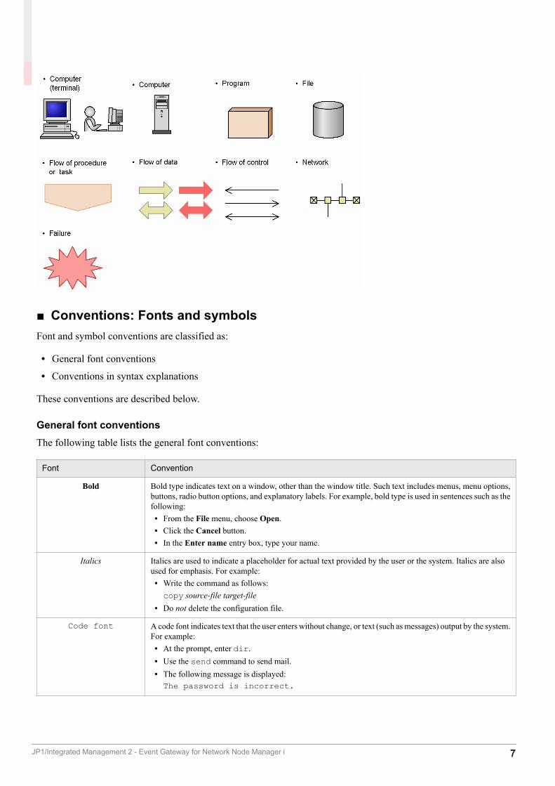
■ Conventions: Fonts and symbolsFont and symbol conventions are classified as:
• General font conventions
• Conventions in syntax explanations
These conventions are described below.
General font conventionsThe following table lists the general font conventions:
Font Convention
Bold Bold type indicates text on a window, other than the window title. Such text includes menus, menu options,buttons, radio button options, and explanatory labels. For example, bold type is used in sentences such as thefollowing:• From the File menu, choose Open.• Click the Cancel button.• In the Enter name entry box, type your name.
Italics Italics are used to indicate a placeholder for actual text provided by the user or the system. Italics are alsoused for emphasis. For example:• Write the command as follows:copy source-file target-file
• Do not delete the configuration file.
Code font A code font indicates text that the user enters without change, or text (such as messages) output by the system.For example:• At the prompt, enter dir.• Use the send command to send mail.• The following message is displayed:The password is incorrect.
JP1/Integrated Management 2 - Event Gateway for Network Node Manager i 7
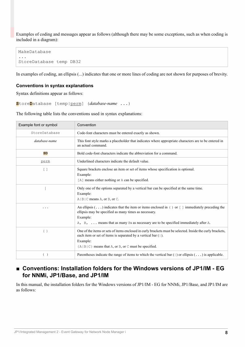
Examples of coding and messages appear as follows (although there may be some exceptions, such as when coding isincluded in a diagram):
MakeDatabase...StoreDatabase temp DB32
In examples of coding, an ellipsis (...) indicates that one or more lines of coding are not shown for purposes of brevity.
Conventions in syntax explanationsSyntax definitions appear as follows:
StoreDatabase [temp|perm] (database-name ...)
The following table lists the conventions used in syntax explanations:
Example font or symbol Convention
StoreDatabase Code-font characters must be entered exactly as shown.
database-name This font style marks a placeholder that indicates where appropriate characters are to be entered inan actual command.
SD Bold code-font characters indicate the abbreviation for a command.
perm Underlined characters indicate the default value.
[ ] Square brackets enclose an item or set of items whose specification is optional.Example:[A] means either nothing or A can be specified.
| Only one of the options separated by a vertical bar can be specified at the same time.Example:A|B|C means A, or B, or C.
... An ellipsis (...) indicates that the item or items enclosed in ( ) or [ ] immediately preceding theellipsis may be specified as many times as necessary.Example:A, B, ... means that as many Bs as necessary are to be specified immediately after A.
{ } One of the items or sets of items enclosed in curly brackets must be selected. Inside the curly brackets,each item or set of items is separated by a vertical bar (|).Example:{A|B|C} means that A, or B, or C must be specified.
( ) Parentheses indicate the range of items to which the vertical bar (|) or ellipsis (...) is applicable.
■ Conventions: Installation folders for the Windows versions of JP1/IM - EGfor NNMi, JP1/Base, and JP1/IM
In this manual, the installation folders for the Windows versions of JP1/IM - EG for NNMi, JP1/Base, and JP1/IM areas follows:
JP1/Integrated Management 2 - Event Gateway for Network Node Manager i 8

Product name Installation folder Default installation folder#
JP1/IM - EG for NNMi EG-for-NNMi-path system-drive:\Program Files(x86)\HITACHI\JP1EG4NNMI
JP1/Base Base-path system-drive:\Program Files\HITACHI\JP1Base
JP1/IM - Manager Console-path system-drive:\Program Files\HITACHI\JP1Cons
#: Denotes the installation folder for each product when a default installation is performed.
■ Conventions: Meaning of "Administrator permissions" in this manualIn this manual, Administrator permissions refers to the Administrator permissions for the local PC. Provided that theuser has Administrator permissions for the local PC, operations are the same whether they are performed with a localuser account, a domain user account, or in an Active Directory environment.
JP1/Integrated Management 2 - Event Gateway for Network Node Manager i 9
Contents
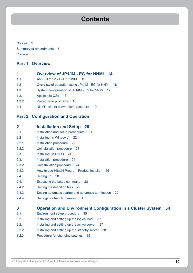
Notices 2
Summary of amendments 5
Preface 6
Part 1: Overview
1 Overview of JP1/IM - EG for NNMi 141.1 About JP1/IM - EG for NNMi 15
1.2 Overview of operation using JP1/IM - EG for NNMi 16
1.3 System configuration of JP1/IM - EG for NNMi 17
1.3.1 Applicable OSs 17
1.3.2 Prerequisite programs 18
1.4 NNMi incident conversion procedure 19
Part 2: Configuration and Operation
2 Installation and Setup 202.1 Installation and setup procedures 21
2.2 Installing (in Windows) 22
2.2.1 Installation procedure 22
2.2.2 Uninstallation procedure 23
2.3 Installing (in UNIX) 24
2.3.1 Installation procedure 24
2.3.2 Uninstallation procedure 24
2.3.3 How to use Hitachi Program Product Installer 25
2.4 Setting up 28
2.4.1 Executing the setup command 28
2.4.2 Setting the definition files 29
2.4.3 Setting automatic startup and automatic termination 29
2.4.4 Settings for handling errors 31
3 Operation and Environment Configuration in a Cluster System 343.1 Environment setup procedure 35
3.2 Installing and setting up the logical host 37
3.2.1 Installing and setting up the active server 37
3.2.2 Installing and setting up the standby server 38
3.2.3 Procedure for changing settings 39
JP1/Integrated Management 2 - Event Gateway for Network Node Manager i 10
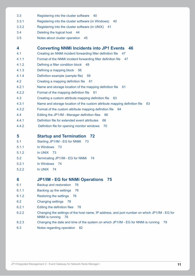
3.3 Registering into the cluster software 40
3.3.1 Registering into the cluster software (in Windows) 40
3.3.2 Registering into the cluster software (in UNIX) 41
3.4 Deleting the logical host 44
3.5 Notes about cluster operation 45
4 Converting NNMi Incidents into JP1 Events 464.1 Creating an NNMi incident forwarding filter definition file 47
4.1.1 Format of the NNMi incident forwarding filter definition file 47
4.1.2 Defining a filter condition block 49
4.1.3 Defining a mapping block 56
4.1.4 Definition example (sample file) 59
4.2 Creating a mapping definition file 61
4.2.1 Name and storage location of the mapping definition file 61
4.2.2 Format of the mapping definition file 61
4.3 Creating a custom attribute mapping definition file 63
4.3.1 Name and storage location of the custom attribute mapping definition file 63
4.3.2 Format of the custom attribute mapping definition file 64
4.4 Editing the JP1/IM - Manager definition files 66
4.4.1 Definition file for extended event attributes 66
4.4.2 Definition file for opening monitor windows 70
5 Startup and Termination 725.1 Starting JP1/IM - EG for NNMi 73
5.1.1 In Windows 73
5.1.2 In UNIX 73
5.2 Terminating JP1/IM - EG for NNMi 74
5.2.1 In Windows 74
5.2.2 In UNIX 74
6 JP1/IM - EG for NNMi Operations 756.1 Backup and restoration 76
6.1.1 Backing up the settings 76
6.1.2 Restoring the settings 76
6.2 Changing settings 78
6.2.1 Editing the definition files 78
6.2.2 Changing the settings of the host name, IP address, and port number on which JP1/IM - EG forNNMi is running 78
6.2.3 Changing the date and time of the system on which JP1/IM - EG for NNMi is running 79
6.3 Notes regarding operation 82
JP1/Integrated Management 2 - Event Gateway for Network Node Manager i 11
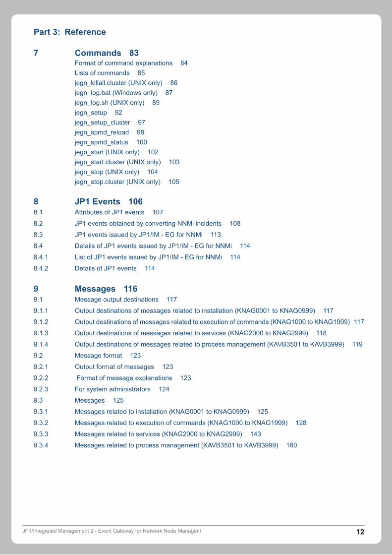
Part 3: Reference
7 Commands 83Format of command explanations 84Lists of commands 85jegn_killall.cluster (UNIX only) 86jegn_log.bat (Windows only) 87jegn_log.sh (UNIX only) 89jegn_setup 92jegn_setup_cluster 97jegn_spmd_reload 98jegn_spmd_status 100jegn_start (UNIX only) 102jegn_start.cluster (UNIX only) 103jegn_stop (UNIX only) 104jegn_stop.cluster (UNIX only) 105
8 JP1 Events 1068.1 Attributes of JP1 events 107
8.2 JP1 events obtained by converting NNMi incidents 108
8.3 JP1 events issued by JP1/IM - EG for NNMi 113
8.4 Details of JP1 events issued by JP1/IM - EG for NNMi 114
8.4.1 List of JP1 events issued by JP1/IM - EG for NNMi 114
8.4.2 Details of JP1 events 114
9 Messages 1169.1 Message output destinations 117
9.1.1 Output destinations of messages related to installation (KNAG0001 to KNAG0999) 117
9.1.2 Output destinations of messages related to execution of commands (KNAG1000 to KNAG1999) 117
9.1.3 Output destinations of messages related to services (KNAG2000 to KNAG2999) 118
9.1.4 Output destinations of messages related to process management (KAVB3501 to KAVB3999) 119
9.2 Message format 123
9.2.1 Output format of messages 123
9.2.2 Format of message explanations 123
9.2.3 For system administrators 124
9.3 Messages 125
9.3.1 Messages related to installation (KNAG0001 to KNAG0999) 125
9.3.2 Messages related to execution of commands (KNAG1000 to KNAG1999) 128
9.3.3 Messages related to services (KNAG2000 to KNAG2999) 143
9.3.4 Messages related to process management (KAVB3501 to KAVB3999) 160
JP1/Integrated Management 2 - Event Gateway for Network Node Manager i 12
Part 4: Troubleshooting
10 Troubleshooting 18610.1 Troubleshooting procedure 187
10.2 Types of log information 188
10.2.1 Integrated trace log 188
10.2.2 Trace log for issued JP1 events 189
10.2.3 Trace logs for each process 192
10.3 Data to be collected in the event of an error 193
10.3.1 Data to be collected (in Windows) 193
10.3.2 Data to be collected (in UNIX) 200
Appendixes 210A Lists of Files and Directories 211
A.1 Files and folders (in Windows) 211
A.2 Files and directories (in UNIX) 212
B Lists of Processes 215
B.1 List of processes (in Windows) 215
B.2 List of processes (in UNIX) 215
C List of Limit Values 216
D Performance and Estimation 217
E Regular Expressions 218
E.1 Syntax for regular expressions 218
E.2 How to specify regular expressions 219
E.3 Hints on using regular expressions 220
E.4 Examples of regular expressions 220
F Definition Files 222
F.1 Extended startup process definition file (jegn_service_0700.conf) 223
F.2 JP1/IM - EG for NNMi parameter definition file (jegn_param_V7.conf) 224
G Version Changes 226
G.1 Changes in version 12-00 226
G.2 Changes in version 11-50 226
H Reference Material for this Manual 227
H.1 Related publications 227
H.2 Conventions: Abbreviations 227
H.3 Acronyms 228
H.4 Conventions: KB, MB, GB and TB 229
I Glossary 230
Index 235
JP1/Integrated Management 2 - Event Gateway for Network Node Manager i 13
Part 1: Overview
1 Overview of JP1/IM - EG for NNMi
This chapter provides an overview of JP1/IM - EG for NNMi and describes the system configurationand the procedure for converting NNMi incidents.
JP1/Integrated Management 2 - Event Gateway for Network Node Manager i 14

1.1 About JP1/IM - EG for NNMi
When an event such as a failure occurs on a network device that is managed by JP1/NNMi, an NNMi incident is issued.JP1/IM - EG for NNMi is a product that converts such NNMi incidents into JP1 events so that they are in a format thatcan be managed by JP1/Base.
The converted JP1 events are forwarded to a JP1/IM integrated management system product, which manages andmonitors the converted JP1 events in the same way that it manages and monitors JP1 events that are issued by otherJP1-series programs.
JP1/IM achieves integrated management of systems by linking with middleware products (JP1 series products), suchas for job management and storage management, as well as with JP1/IM - EG for NNMi, thus enabling it to managethe configuration and operations of the entire system.
In this manual, JP1/NNMi are abbreviated as NNMi.
1. Overview of JP1/IM - EG for NNMi
JP1/Integrated Management 2 - Event Gateway for Network Node Manager i 15
1.2 Overview of operation using JP1/IM - EG for NNMi
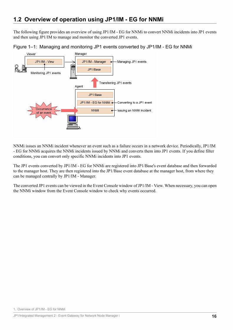
The following figure provides an overview of using JP1/IM - EG for NNMi to convert NNMi incidents into JP1 eventsand then using JP1/IM to manage and monitor the converted JP1 events.
Figure 1‒1: Managing and monitoring JP1 events converted by JP1/IM - EG for NNMi
NNMi issues an NNMi incident whenever an event such as a failure occurs in a network device. Periodically, JP1/IM- EG for NNMi acquires the NNMi incidents issued by NNMi and converts them into JP1 events. If you define filterconditions, you can convert only specific NNMi incidents into JP1 events.
The JP1 events converted by JP1/IM - EG for NNMi are registered into JP1/Base's event database and then forwardedto the manager host. They are then registered into the JP1/Base event database at the manager host, from where theycan be managed centrally by JP1/IM - Manager.
The converted JP1 events can be viewed in the Event Console window of JP1/IM - View. When necessary, you can openthe NNMi window from the Event Console window to check why events occurred.
1. Overview of JP1/IM - EG for NNMi
JP1/Integrated Management 2 - Event Gateway for Network Node Manager i 16
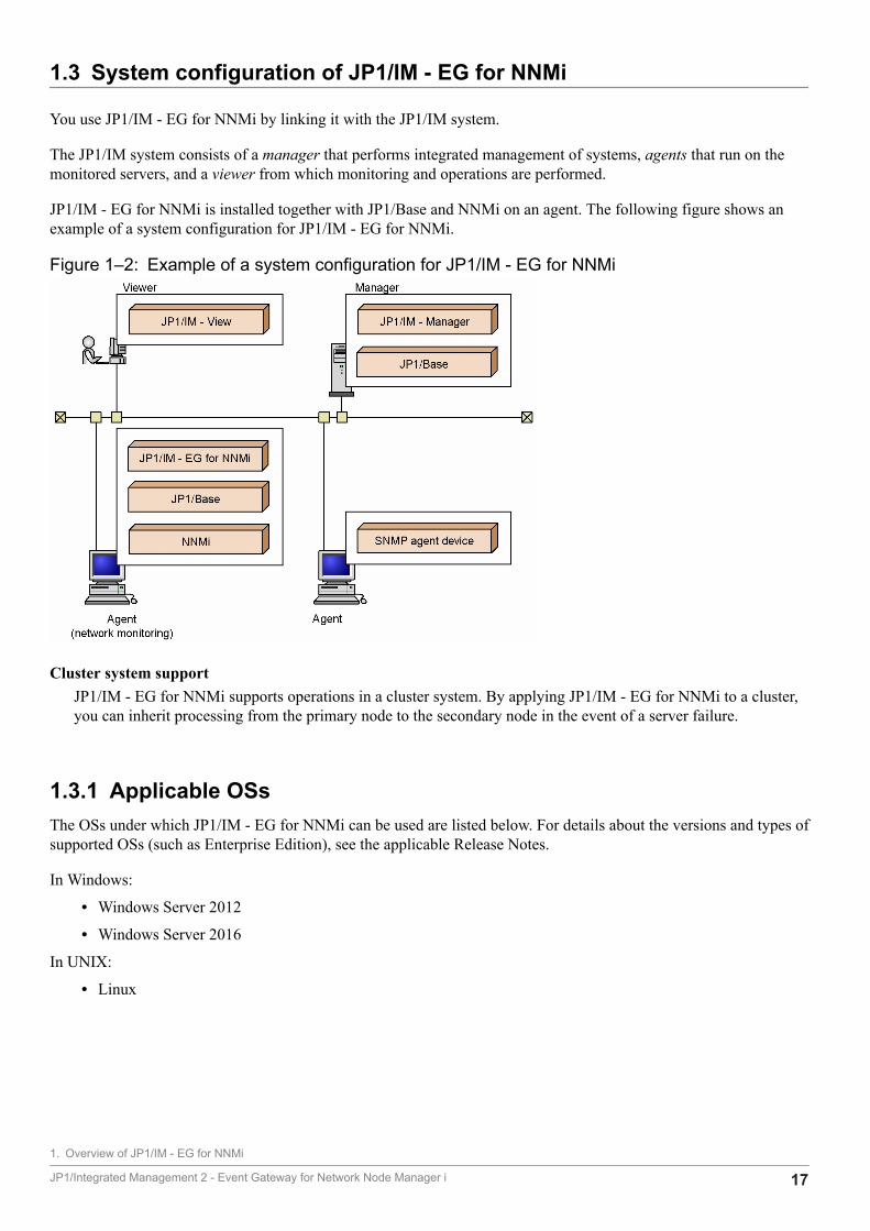
1.3 System configuration of JP1/IM - EG for NNMi
You use JP1/IM - EG for NNMi by linking it with the JP1/IM system.
The JP1/IM system consists of a manager that performs integrated management of systems, agents that run on themonitored servers, and a viewer from which monitoring and operations are performed.
JP1/IM - EG for NNMi is installed together with JP1/Base and NNMi on an agent. The following figure shows anexample of a system configuration for JP1/IM - EG for NNMi.
Figure 1‒2: Example of a system configuration for JP1/IM - EG for NNMi
Cluster system supportJP1/IM - EG for NNMi supports operations in a cluster system. By applying JP1/IM - EG for NNMi to a cluster,you can inherit processing from the primary node to the secondary node in the event of a server failure.
1.3.1 Applicable OSsThe OSs under which JP1/IM - EG for NNMi can be used are listed below. For details about the versions and types ofsupported OSs (such as Enterprise Edition), see the applicable Release Notes.
In Windows:
• Windows Server 2012
• Windows Server 2016
In UNIX:
• Linux
1. Overview of JP1/IM - EG for NNMi
JP1/Integrated Management 2 - Event Gateway for Network Node Manager i 17

1.3.2 Prerequisite programsThis subsection describes the prerequisite programs for JP1/IM - EG for NNMi and the JP1/IM system. For details, seethe Release Notes for the applicable products.
(1) Prerequisite programs for JP1/IM - EG for NNMiThe following table lists the prerequisite programs for JP1/IM - EG for NNMi.
• JP1/Base
• NNMi
(2) Prerequisite programs for JP1/IM system
(a) Prerequisite programs for the manager hostThe prerequisite programs for the manager host are listed below.
• JP1/IM - Manager
• JP1/Base
(b) Prerequisite program for the viewer hostThe prerequisite program for viewer host is listed below.
• JP1/IM - View
A Web browser is required in order to open the NNMi windows from a monitor. For details about the supported Webbrowsers, see the documentation for the NNMi product.
1. Overview of JP1/IM - EG for NNMi
JP1/Integrated Management 2 - Event Gateway for Network Node Manager i 18
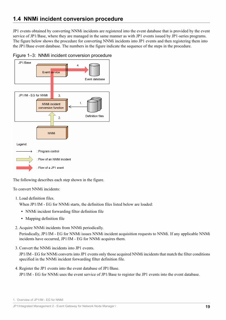
1.4 NNMi incident conversion procedure
JP1 events obtained by converting NNMi incidents are registered into the event database that is provided by the eventservice of JP1/Base, where they are managed in the same manner as with JP1 events issued by JP1-series programs.The figure below shows the procedure for converting NNMi incidents into JP1 events and then registering them intothe JP1/Base event database. The numbers in the figure indicate the sequence of the steps in the procedure.
Figure 1‒3: NNMi incident conversion procedure
The following describes each step shown in the figure.
To convert NNMi incidents:
1. Load definition files.When JP1/IM - EG for NNMi starts, the definition files listed below are loaded:
• NNMi incident forwarding filter definition file
• Mapping definition file
2. Acquire NNMi incidents from NNMi periodically.Periodically, JP1/IM - EG for NNMi issues NNMi incident acquisition requests to NNMi. If any applicable NNMiincidents have occurred, JP1/IM - EG for NNMi acquires them.
3. Convert the NNMi incidents into JP1 events.JP1/IM - EG for NNMi converts into JP1 events only those acquired NNMi incidents that match the filter conditionsspecified in the NNMi incident forwarding filter definition file.
4. Register the JP1 events into the event database of JP1/Base.JP1/IM - EG for NNMi uses the event service of JP1/Base to register the JP1 events into the event database.
1. Overview of JP1/IM - EG for NNMi
JP1/Integrated Management 2 - Event Gateway for Network Node Manager i 19

Part 2: Configuration and Operation
2 Installation and Setup
This chapter describes how to install, set up, and uninstall JP1/IM - EG for NNMi.
JP1/Integrated Management 2 - Event Gateway for Network Node Manager i 20
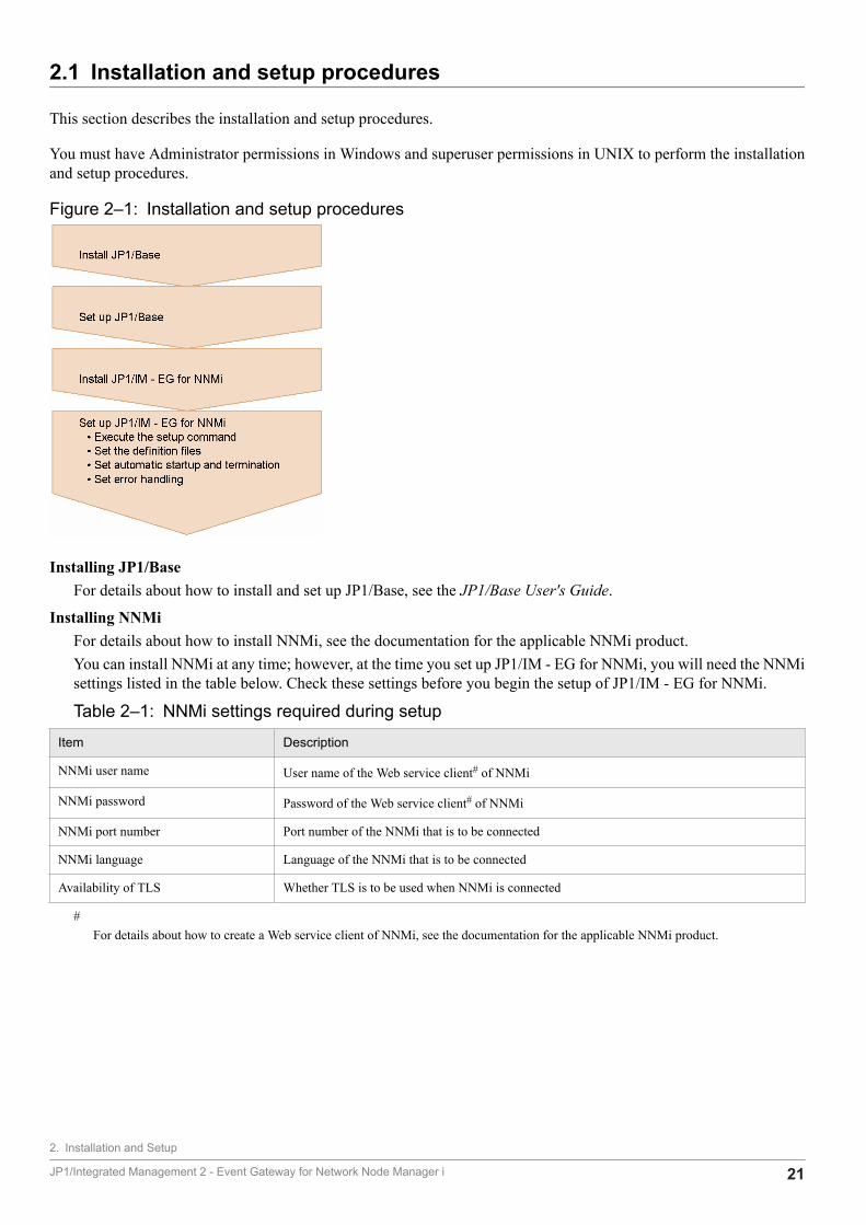
2.1 Installation and setup procedures
This section describes the installation and setup procedures.
You must have Administrator permissions in Windows and superuser permissions in UNIX to perform the installationand setup procedures.
Figure 2‒1: Installation and setup procedures
Installing JP1/BaseFor details about how to install and set up JP1/Base, see the JP1/Base User's Guide.
Installing NNMiFor details about how to install NNMi, see the documentation for the applicable NNMi product.You can install NNMi at any time; however, at the time you set up JP1/IM - EG for NNMi, you will need the NNMisettings listed in the table below. Check these settings before you begin the setup of JP1/IM - EG for NNMi.
Table 2‒1: NNMi settings required during setup
Item Description
NNMi user name User name of the Web service client# of NNMi
NNMi password Password of the Web service client# of NNMi
NNMi port number Port number of the NNMi that is to be connected
NNMi language Language of the NNMi that is to be connected
Availability of TLS Whether TLS is to be used when NNMi is connected
#For details about how to create a Web service client of NNMi, see the documentation for the applicable NNMi product.
2. Installation and Setup
JP1/Integrated Management 2 - Event Gateway for Network Node Manager i 21
2.2 Installing (in Windows)
This section describes how to install and uninstall JP1/IM - EG for NNMi in a Windows environment.
2.2.1 Installation procedureJP1/IM - EG for NNMi requires JP1/Base as a prerequisite product. You must install JP1/Base before you can installJP1/IM - EG for NNMi.
The following table lists the language type for JP1/IM - EG for NNMi that is specified based on OS system locale.
Table 2‒2: Language type for JP1/IM - EG for NNMi (in Windows)
OS system locale Language type
Japanese Japanese
English English
ImportantOnce you have installed JP1/IM - EG for NNMi, you cannot change the language environment. To changethe language environment, uninstall JP1/IM - EG for NNMi, change the system locale for the OS, and theninstall JP1/IM - EG for NNMi again.
To install JP1/IM - EG for NNMi:
1. Terminate the programs.Stop the JP1/Base services.Stop the NNMi services.
2. Insert the distribution medium into the corresponding drive.Follow the instructions of the installer, which starts automatically. In the case of a new installation, specify thefollowing information:
• User information
• Installation folderThe default installation folder is as follows:system-drive:\Program Files(x86)\HITACHI\JP1EG4NNMI
In the case of an overwrite installation or upgrade installation, the existing information specified during the previousinstallation is inherited. To change the installation folder, uninstall the product and then re-install it.
About remote installation using JP1/Software DistributionRemote installation (software distribution) by JP1/Software Distribution is supported for JP1/IM - EG for NNMi.For details about how to use JP1/Software Distribution to perform remote installation, see the Job ManagementPartner 1/Software Distribution Administrator's Guide Volume 1.
About overwrite installation and upgrade installationBefore you perform an overwrite installation or upgrade installation of JP1/IM - EG for NNMi, stop the services ofJP1/IM - EG for NNMi.
2. Installation and Setup
JP1/Integrated Management 2 - Event Gateway for Network Node Manager i 22
2.2.2 Uninstallation procedureTo uninstall JP1/IM - EG for NNMi:
1. Terminate the programs.Stop the JP1/Base services.Stop the NNMi services.Stop the JP1/IM - EG for NNMi services.
2. Delete JP1/IM - EG for NNMi.In Windows, choose Control Panel, then Add or Remove Programs, and then remove JP1/IntegratedManagement 2 - Event Gateway for Network Node Manager i.
3. Delete user files.Definition files and log files that were created after installation and files that may be edited by the user are notdeleted. To delete these files, use Explorer to delete the folder in which JP1/IM - EG for NNMi had been installed.
ImportantWhen JP1/Base is uninstalled, the definition information for JP1/IM - EG for NNMi is also deleted.JP1/IM - EG for NNMi will no longer run, even when JP1/Base is reinstalled. In this case, an overwriteinstallation of JP1/IM - EG for NNMi needs to be performed.
2. Installation and Setup
JP1/Integrated Management 2 - Event Gateway for Network Node Manager i 23
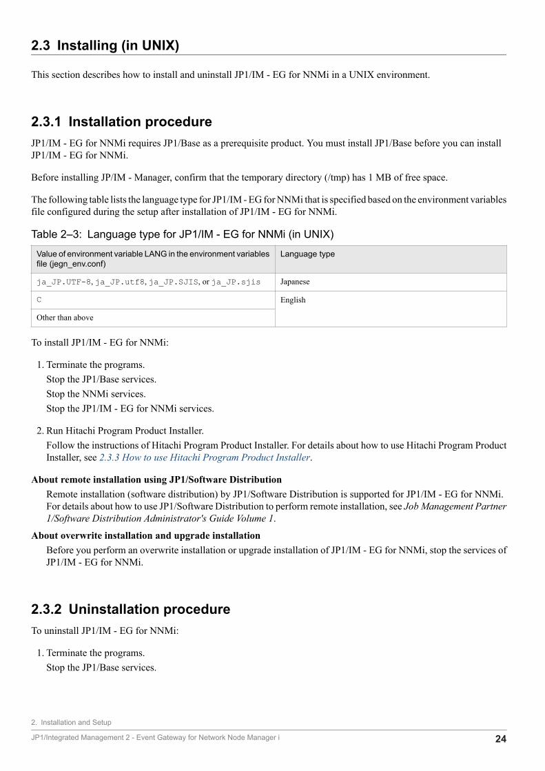
2.3 Installing (in UNIX)
This section describes how to install and uninstall JP1/IM - EG for NNMi in a UNIX environment.
2.3.1 Installation procedureJP1/IM - EG for NNMi requires JP1/Base as a prerequisite product. You must install JP1/Base before you can installJP1/IM - EG for NNMi.
Before installing JP/IM - Manager, confirm that the temporary directory (/tmp) has 1 MB of free space.
The following table lists the language type for JP1/IM - EG for NNMi that is specified based on the environment variablesfile configured during the setup after installation of JP1/IM - EG for NNMi.
Table 2‒3: Language type for JP1/IM - EG for NNMi (in UNIX)
Value of environment variable LANG in the environment variablesfile (jegn_env.conf)
Language type
ja_JP.UTF-8, ja_JP.utf8, ja_JP.SJIS, or ja_JP.sjis Japanese
C English
Other than above
To install JP1/IM - EG for NNMi:
1. Terminate the programs.Stop the JP1/Base services.Stop the NNMi services.Stop the JP1/IM - EG for NNMi services.
2. Run Hitachi Program Product Installer.Follow the instructions of Hitachi Program Product Installer. For details about how to use Hitachi Program ProductInstaller, see 2.3.3 How to use Hitachi Program Product Installer.
About remote installation using JP1/Software DistributionRemote installation (software distribution) by JP1/Software Distribution is supported for JP1/IM - EG for NNMi.For details about how to use JP1/Software Distribution to perform remote installation, see Job Management Partner1/Software Distribution Administrator's Guide Volume 1.
About overwrite installation and upgrade installationBefore you perform an overwrite installation or upgrade installation of JP1/IM - EG for NNMi, stop the services ofJP1/IM - EG for NNMi.
2.3.2 Uninstallation procedureTo uninstall JP1/IM - EG for NNMi:
1. Terminate the programs.Stop the JP1/Base services.
2. Installation and Setup
JP1/Integrated Management 2 - Event Gateway for Network Node Manager i 24
Stop the NNMi services.
2. Back up the user files.Directories containing files, such as definition files and log files, will also be deleted. If necessary, back them upbefore proceeding to the next step.
3. Run Hitachi Program Product Installer.Follow the instructions of Hitachi Program Product Installer to perform uninstallation. For details about how to useHitachi Program Product Installer, see 2.3.3 How to use Hitachi Program Product Installer.
Important• When JP1/Base is uninstalled, the definition information for JP1/IM - EG for NNMi is also deleted.
JP1/IM - EG for NNMi will no longer run, even when JP1/Base is reinstalled. In this case, an overwriteinstallation of JP1/IM - EG for NNMi needs to be performed.
• After uninstalling JP1/IM - Manager, check if the following directories remain. If any remain, deletethem.- /etc/opt/jp1eg4nnmi- /opt/jp1eg4nnmi- /var/opt/jp1eg4nnmi
2.3.3 How to use Hitachi Program Product InstallerHitachi Program Product Installer is stored on the distribution medium of JP1/IM - EG for NNMi. This subsectiondescribes the following procedures:
• How to start Hitachi Program Product Installer
• How to use Hitachi Program Product Installer to install JP1/IM - EG for NNMi
• How to use Hitachi Program Product Installer to uninstall JP1/IM - EG for NNMi
• How to use Hitachi Program Product Installer to check the version of currently installed Hitachi products
User permissions for execution of Hitachi Program Product InstallerYou must have superuser permissions in order to use Hitachi Program Product Installer. Either log in as a superuseror use the su command to change to a superuser.
(1) Starting Hitachi Program Product InstallerTo start Hitachi Program Product Installer:
1. Insert the JP1/IM - EG for NNMi distribution medium in the drive.
2. Mount the distribution medium.The mounting method depends on the OS, hardware, and environment. For details about the mounting method, seethe documentation for the OS.
• In Linux/bin/mount -r -o mode=0544 /dev/cdrom /mnt/cdrom
Note that the underlined distribution medium file system mount directory name depends on the environment.
2. Installation and Setup
JP1/Integrated Management 2 - Event Gateway for Network Node Manager i 25
3. Start Hitachi Program Product Installer.The directory and file names on the distribution medium may not be as shown here depending on the machineenvironment. Use the Is command to check the directory and file names, and make sure to use the displayed names.
• In Linux/mnt/cdrom/linux/setup /mnt/cdrom
Replace the underlined part with the actual distribution medium mount directory name.
4. Unmount the distribution medium.When installation is completed, unmount the distribution medium. For details about how to unmount a distributionmedium, see the documentation for the OS.
• In Linux/bin/umount /mnt/cdrom
Replace the underlined part with the actual distribution medium mount directory name.
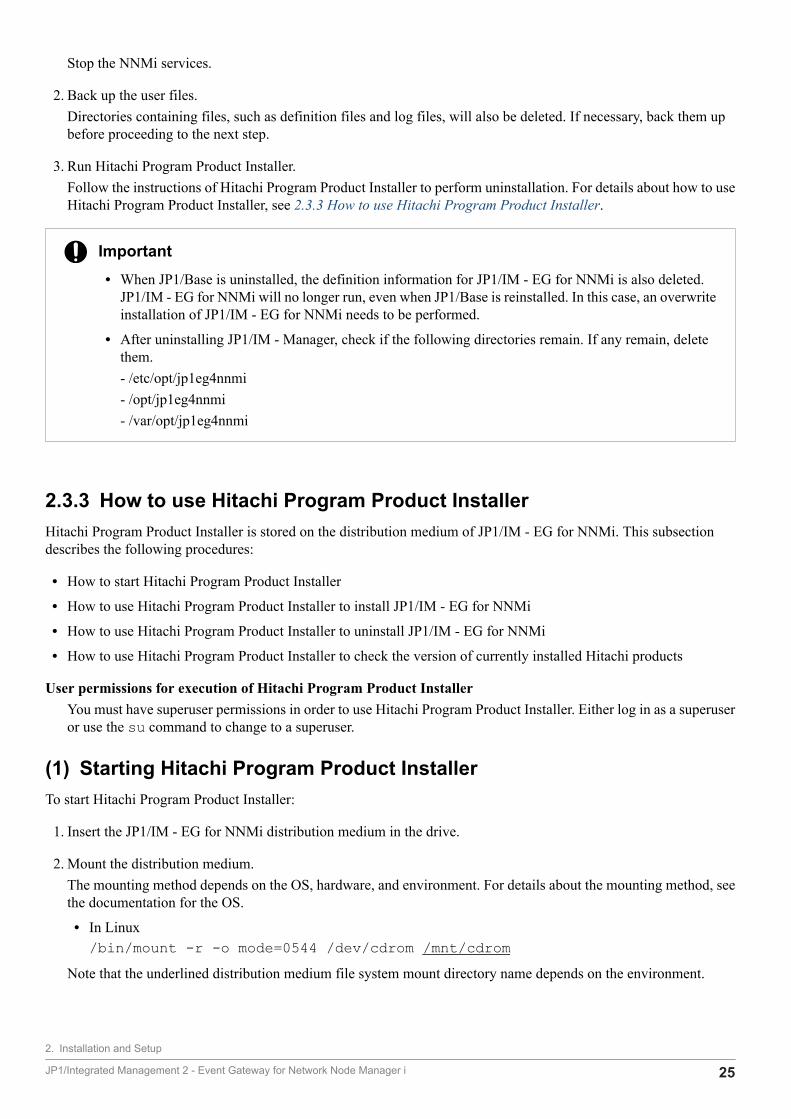
(2) Installing JP1/IM - EG for NNMiThis subsection describes how to use Hitachi Program Product Installer to install JP1/IM - EG for NNMi. When youstart Hitachi Program Product Installer, the initial window appears.
Figure 2‒2: Example of Hitachi Program Product Installer's initial window
Enter I in the initial window to display a list of software programs that can be installed. Move the cursor to the softwareprogram that you wish to install and press the space bar to select it. Enter I again to install the selected software (JP1/IM - EG for NNMi). When installation is completed, enter Q to return to the initial window.
(3) Uninstalling JP1/IM - EG for NNMiEnter the following command to start Hitachi Program Product Installer:
/etc/hitachi_setup
Hitachi Program Product Installer's initial window is displayed.
Enter D in the initial window to display a list of software programs that can be uninstalled. Move the cursor to thesoftware program that you wish to uninstall and press the space bar to select it. Enter D again to uninstall the selectedsoftware (JP1/IM - EG for NNMi). When uninstallation is completed, enter Q to return to the initial window.
2. Installation and Setup
JP1/Integrated Management 2 - Event Gateway for Network Node Manager i 26

(4) Displaying version informationExecute the following command to start Hitachi Program Product Installer:
/etc/hitachi_setup
Hitachi Program Product Installer's initial window is displayed.
Enter L in the initial window to display a list of Hitachi products that have been installed.
2. Installation and Setup
JP1/Integrated Management 2 - Event Gateway for Network Node Manager i 27
2.4 Setting up
This section describes how to set up JP1/IM - EG for NNMi.
The following figure shows the setup procedure.
Figure 2‒3: Setup procedure
2.4.1 Executing the setup commandAfter you have installed JP1/IM - EG for NNMi, you execute the setup command (jegn_setup) to set up an operatingenvironment for JP1/IM - EG for NNMi.
For details about the jegn_setup command, see jegn_setup in 7. Commands.
The following table lists and describes the information that is set by the jegn_setup command.
Table 2‒4: Information set by the jegn_setup command
Item Description Setting
NNMi user name Sets the user name of the Web service client# of NNMi. Y
NNMi password Sets the password of the Web service client# of NNMi. Y
NNMi port number Sets the port number of the NNMi that is to be connected. --
NNMi language Sets the language of the NNMi that is to be connected. --
NNMi incident re-acquisition interval Sets the interval at which another attempt is to be made to acquire NNMi incidentswhen there are no NNMi incidents to be acquired or in the event of an exceptionsuch as a communication error.
--
NNMi incident acquisition method Sets the first NNMi incident to be acquired in cases where NNMi incidents issuedwhile the JP1/IM - EG for NNMi services are stopped are to be acquired the nexttime the services start (except during the initial start).
--
Availability of TLS Sets whether TLS is to be used when NNMi is connected. --
Legend:Y: Setting is required
2. Installation and Setup
JP1/Integrated Management 2 - Event Gateway for Network Node Manager i 28
--: Setting is optional
#For details about how to create a Web service client of NNMi, see the documentation for the NNMi product.
About overwrite setupYou can use the -update option of the jegn_setup command to change the operating environment of JP1/IM- EG for NNMi.
2.4.2 Setting the definition filesTo convert NNMi incidents into JP1 events and then use JP1/IM to manage and monitor them, you must set the definitionfiles listed in the following table.
Note the following points about the environment variables settings.
• When LC_ALL is not specified, the settings of LC_MESSAGES, LANG, and LC_CTYPE# must be the same.
• When LC_ALL and LC_MESSAGES are not specified, the settings of LANG and LC_CTYPE# must be the same.
#The settings of LC_CTYPE are optional.
Table 2‒5: Definition files to be set
Definition file name Description
NNMi incident forwarding filterdefinition file
This file defines conditions for converting NNMi incidents acquired from NNMi into JP1 events.
Mapping definition file This file defines mapping for displaying category and family labels (which are attributes of NNMi incidents)on the Event Details window of JP1/IM - View.
JP1/IM - Manager definitionfiles
The following two definition files are used by JP1/IM - Manager:
Definition file for extended event attributesThis definition file is used to display the extended attributes specific to JP1/IM - EG for NNMi in theEvent Details window of JP1/IM - View.
Definition file for opening monitor windowsThis definition file is used to open NNMi windows from the Event Console window of JP1/IM - View.
Create the NNMi incident forwarding filter definition file and the mapping definition file by copying the sample filesprovided by JP1/IM - EG for NNMi.
The JP1/IM - Manager definition files are included in JP1/IM - Manager. Normally, there is no need to edit the includeddefinition files. Edit these definition files only when it is necessary to add attributes to be displayed in the Event Detailswindow of JP1/IM - View or change the Web browser to open NNMi windows.
For details about the settings in each definition file, see 4. Converting NNMi Incidents into JP1 Events.
2.4.3 Setting automatic startup and automatic terminationYou must start the services of NNMi and JP1/Base before you can start the services of JP1/IM - EG for NNMi. Theservices of JP1/IM - EG for NNMi must be stopped before you stop the services of NNMi and JP1/Base.
2. Installation and Setup
JP1/Integrated Management 2 - Event Gateway for Network Node Manager i 29
If you set automatic startup and termination of JP1/IM - EG for NNMi, you can specify in advance the service start andtermination sequences. Set automatic startup and termination when necessary.
The settings for automatic startup and termination depend on the OS.
(1) In WindowsIn Windows, use JP1/Base's startup control to set automatic startup and termination of JP1/IM - EG for NNMi. Startupcontrol starts and stops services according to a predefined sequence.
Setting automatic startupYou set automatic startup by specifying the definition of JP1/IM - EG for NNMi in JP1/Base's start sequencedefinition file (JP1SVPRM.DAT). The following shows the definition of JP1/IM - EG for NNMi:
[Jp1IMEGforNNMi]Name=JP1/IM - EG for NNMiServiceName=JP1_IM-EG_for_NNMiStopCommand=<JP1/IM - EG for NNMi Path>\bin\jegn_spmd_stop.exe
At the time of a new installation, these lines are commented out by inclusion of a hash mark (#) at the beginning ofeach line. Delete these hash marks.The services are started in the order specified. If you edit the start sequence definition file, make sure that you enterthe definition of JP1/IM - EG for NNMi after the definition of JP1/Base.
Setting automatic terminationIn order to use JP1/Base's startup control to set automatic termination of JP1/IM - EG for NNMi, JP1/Power Monitormust be installed on the same computer. For details about JP1/Power Monitor, see the manual Job ManagementPartner 1/Power Monitor Description, User's Guide and Reference.When JP1/Power Monitor is used to turn off the power, the services for which the termination command(StopCommand=) is specified are stopped in the reverse order of their startup among all the services specified inJP1/Base's start sequence definition file.Express the termination command as an absolute path. It is specified as follows during the new installation:
StopCommand=JP1/IM-EG-for-NNMi-path\bin\jegn_spmd_stop.exe
Replace JP1/IM-EG-for-NNMi-path with the actual JP1/IM - EG for NNMi installation path. If the installation pathcontains a space, enclose character strings following StopCommand= in double-quotation marks (").
(2) In UNIXIn UNIX, use an automated startup script and an automated stop script to set automatic startup and termination of JP1/IM - EG for NNMi.
Setting automatic startupExecute the following command to copy the automated startup script (jegn_start):
# cd /etc/opt/jp1eg4nnmi# cp -p jegn_start.model jegn_start
When you execute the above command, the automated startup script is called when the system starts and JP1/IM -EG for NNMi is started automatically. For details about the automated startup script, see jegn_start (UNIX only) in7. Commands.
Setting automatic terminationExecute the following command to copy the automated stop script (jegn_stop):
2. Installation and Setup
JP1/Integrated Management 2 - Event Gateway for Network Node Manager i 30
# cd /etc/opt/jp1eg4nnmi# cp -p jegn_stop.model jegn_stop
When you execute the above command, the automated stop script is called when the system is terminated and JP1/IM - EG for NNMi is terminated automatically. For details about the automated stop script, see jegn_stop (UNIXonly) in 7. Commands.
2.4.4 Settings for handling errorsJP1/IM - EG for NNMi provides various measures for handling errors in JP1/IM - EG for NNMi, such as a tool forcollecting data needed for investigation of errors and a function for automatically restarting the process in the event ofan abnormal process termination.
This subsection describes the settings for handling JP1/IM - EG for NNMi errors.
(1) Preparations for collecting data in the event of an error (Windows only)If a JP1/IM - EG for NNMi process stops due to an application error, while the error dialog box is displayed, use thefollowing procedure to collect a user dump:
1. Start Task Manager.You can use either of the following procedures to start Task Manager:
• Right-click a blank area on the task bar and choose Task Manager.
• Press Ctrl + Shift + Esc keys to start Task Manager.
2. Click the Process tab.
3. Right-click the name of the JP1/IM - EG for NNMi process that was stopped by an application error, and then chooseCreate Dump File.
4. When a dialog box showing the user dump output destination path opens, collect a dump from there.
ImportantIf the error dialog box is closed, a normal dump cannot be collected, and consequently you will not beable to collect a user dump. If you closed the error dialog box by mistake (by clicking OK, for example)before collecting a user dump, reproduce the error and then collect a user dump.
(2) Settings for restarting after an abnormal process terminationA process is generated when JP1/IM - EG for NNMi starts. JP1/IM - EG for NNMi enables you to make settings so thatthe process will restart automatically after it has terminated abnormally for some reason.
To specify the settings for process restart after abnormal termination of the process:
1. Specify process restart.Edit the extended startup process definition file (jegn_service_0700.conf). This file is stored at thefollowing locations:
In Windows:• Physical host: EG-for-NNMi-path\conf
2. Installation and Setup
JP1/Integrated Management 2 - Event Gateway for Network Node Manager i 31
• Logical host: shared-folder\JP1EG4NNMI\confIn UNIX:
• Physical host: /etc/opt/jp1eg4nnmi/conf• Logical host: shared-directory/jp1eg4nnmi/conf
The relevant parameter is the fourth value of the values separated by the vertical bar (|). Set either 0 (do not restart(default)) or 1 (restart). Do not change any other parameter values.For details about the extended startup process definition file, see F.1 Extended startup process definition file(jegn_service_0700.conf).
2. Apply the settings.Either restart JP1/IM - EG for NNMi or execute the jegn_spmd_reload command to apply the settings. Fordetails about the jegn_spmd_reload command, see jegn_spmd_reload in 7. Commands.
3. Suppress error reporting to Microsoft (Windows only).In the case of Windows, you must specify settings so that the Microsoft error reporting dialog box, which is displayedin the event of error detection, will not be displayed. This is because a process cannot restart if this dialog box isdisplayed.
In Windows Server 2012:1. In the Control Panel, choose System and Security, Action Center, and then Maintenance.2. Under Check for solutions to problem reports, click Settings.3. In the Windows Error Reporting Configuration dialog box, select I don't want to participate, and don'task me again.4. Click OK.
In Windows Server 2016:1. In the Run text box, enter gpedit.msc, and then click OK.2. In the Local Group Policy Editor, click Computer Configuration, Administrative Templates, WindowsComponents, and then Windows Error Reporting.3. Right-click Disable Windows Error Reporting in the right pane of the window, and then select Edit.4. In the settings window, select the Enabled radio button.5. Click OK.
(3) Setting JP1 event issuance in the event of an abnormal processtermination
JP1/IM - EG for NNMi enables you to issue JP1 events in the event of automatic recovery from a process error orabnormal termination. By issuing JP1 events, you can manage the error logs of JP1/IM - EG for NNMi itself.
To specify settings for JP1 event issuance:
1. Set JP1 event issuance.Edit the JP1/IM - EG for NNMi parameter definition file (jegn_param_V7.conf). This file is stored at thefollowing locations:
In Windows:• Physical host: EG-for-NNMi-path\conf• Logical host: shared-folder\JP1EG4NNMI\conf
2. Installation and Setup
JP1/Integrated Management 2 - Event Gateway for Network Node Manager i 32

In UNIX:• Physical host: /etc/opt/jp1eg4nnmi/conf• Logical host: shared-directory/jp1eg4nnmi/conf
In this file, SEND_PROCESS_TERMINATED_ABNORMALLY_EVENT andSEND_PROCESS_RESTART_EVENT are the JP1 event issuance setting parameters. To issue JP1 events, changethe values of these parameters to dword:1.For details about the JP1/IM - EG for NNMi parameter definition file, see F.2 JP1/IM - EG for NNMi parameterdefinition file (jegn_param_V7.conf).
2. Execute the jbssetcnf command to apply the definition information.For details about the jbssetcnf command, see the JP1/Base User's Guide.
3. Restart JP1/IM - EG for NNMi.The specified settings take effect after the restart.
2. Installation and Setup
JP1/Integrated Management 2 - Event Gateway for Network Node Manager i 33

3 Operation and Environment Configuration in a Cluster System
This chapter describes use of JP1/IM - EG for NNMi in a cluster system and the setup procedure.
For an overview of cluster systems, see the JP1/Base User's Guide.
JP1/Integrated Management 2 - Event Gateway for Network Node Manager i 34
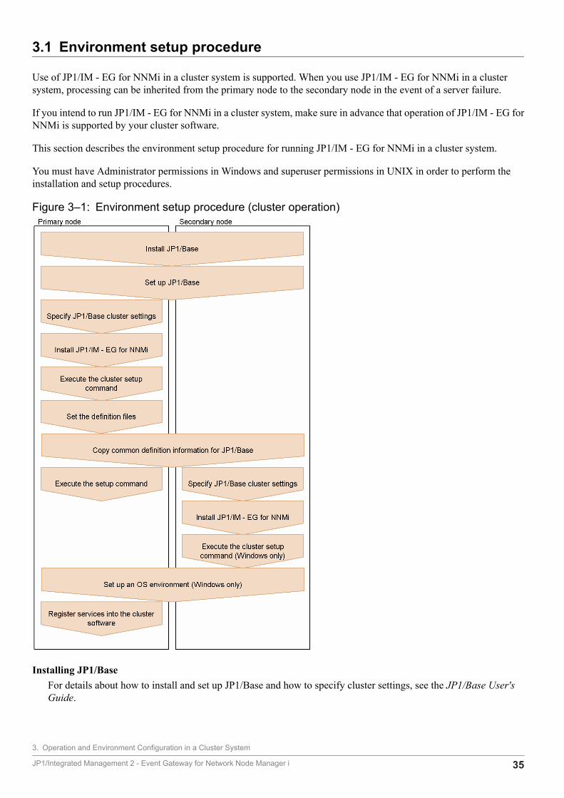
3.1 Environment setup procedure
Use of JP1/IM - EG for NNMi in a cluster system is supported. When you use JP1/IM - EG for NNMi in a clustersystem, processing can be inherited from the primary node to the secondary node in the event of a server failure.
If you intend to run JP1/IM - EG for NNMi in a cluster system, make sure in advance that operation of JP1/IM - EG forNNMi is supported by your cluster software.
This section describes the environment setup procedure for running JP1/IM - EG for NNMi in a cluster system.
You must have Administrator permissions in Windows and superuser permissions in UNIX in order to perform theinstallation and setup procedures.
Figure 3‒1: Environment setup procedure (cluster operation)
Installing JP1/BaseFor details about how to install and set up JP1/Base and how to specify cluster settings, see the JP1/Base User'sGuide.
3. Operation and Environment Configuration in a Cluster System
JP1/Integrated Management 2 - Event Gateway for Network Node Manager i 35

Installing NNMiYou can install NNMi at any time. However, if you intend to run JP1/IM - EG for NNMi in a cluster system, youmust first install and set up NNMi. For details about how to set up NNMi, see the manuals and Release Notes forNNMi.At the time you set up JP1/IM - EG for NNMi, you will need the NNMi settings. For details about the NNMi settingsthat will be required during setup, see Table 2-1 NNMi settings required during setup in 2.1 Installation and setupprocedures.
3. Operation and Environment Configuration in a Cluster System
JP1/Integrated Management 2 - Event Gateway for Network Node Manager i 36
3.2 Installing and setting up the logical host
This section describes installation and setup of the logical host for JP1/IM - EG for NNMi.
JP1/IM - EG for NNMi must run on the same logical host where NNMi and JP1/Base run.
Before you start the procedure, check the cluster system information shown in the table below.
Table 3‒1: Items to be checked before you install and set up the logical host
Item to be checked Description
Logical host name Name of the logical host that executes the services of JP1/Base and NNMi
Logical IP address IP address that corresponds to the logical host name
Shared folder (or shared directory) Folder (or directory) on the shared disk that stores the file set for the JP1 execution environment onthe logical host
For details about the prerequisites and the supported scope of cluster operation, see the JP1/Base User's Guide.
After you have finished checking these items, you can start installation and setup.
Important• In Windows, install both the active server and the standby server on the same drive and in the same
folders. Do not install the logical host on the shared disk.
• Before you set up JP1/IM - EG for NNMi in a cluster system, make sure that JP1/IM - EG for NNMion the physical host has terminated. If you set up the cluster system while JP1/IM - EG for NNMi isrunning on the physical host, the logical host services will no longer function correctly. In such a case,you must restart the server to recover the system.
3.2.1 Installing and setting up the active serverTo install and set up the active server:
1. Install and set up JP1/Base.For details about how to install and set up JP1/Base, see the JP1/Base User's Guide.
2. Specify the cluster settings for JP1/Base.Set the logical host for the primary node. For details about the procedure, see the JP1/Base User's Guide.Note that you can specify a maximum of 32 bytes for the logical host name in the process forced terminationcommand (jegn_killall.cluster) (applicable to UNIX only). A process cannot be terminated forcibly ona logical host whose name consists of more than 32 bytes.
3. Install JP1/IM - EG for NNMi.For details about how to install JP1/IM - EG for NNMi, see 2.2 Installing (in Windows) or 2.3 Installing (in UNIX).
4. Set up an OS environment (Windows only).In Windows, if either the Dr. Watson dialog box or the Microsoft error reporting dialog box is set to be displayedwhen an error occurs, failover of JP1/IM - EG for NNMi might fail. For this reason, you must suppress display of
3. Operation and Environment Configuration in a Cluster System
JP1/Integrated Management 2 - Event Gateway for Network Node Manager i 37
these dialog boxes. For details about the suppression method, see 2.4.4(2) Settings for restarting after an abnormalprocess termination.In the event of an error, you might need a memory dump and a crash dump in order to determine the cause of theerror. To be prepared for such errors, we recommend that you set your system to output these dump files. For detailsabout how to specify the settings, see 2.4.4(1) Preparations for collecting data in the event of an error (Windowsonly).
5. Execute the cluster setup command.Execute the cluster setup command (jegn_setup_cluster) to set up an operating environment for JP1/IM -EG for NNMi during cluster operation.jegn_setup_cluster -h logical-host-name -d shared-folderWhenever you execute the jegn_setup_cluster command, the shared disk must be mounted.For details about the jegn_setup_cluster command, see jegn_setup_cluster in 7. Commands.
Note:Use the same time zone in a cluster system.
6. Set the definition files.Set the following definition files:
• NNMi incident forwarding filter definition file
• Mapping definition file
• JP1/IM - Manager definition files
For details about the settings for the definition files, see 4. Converting NNMi Incidents into JP1 Events.
7. Copy the common definition information for JP1/Base.Copy the common definition information for JP1/Base from the active server to the standby server.Execute the jbsgetcnf command of JP1/Base to back up the common definition information located on the activeserver.jbsgetcnf -h logical-host-name > backup-file-nameFor details about the jbsgetcnf command, see the JP1/Base User's Guide.
8. Execute the setup command.Execute the setup command (jegn_setup) to set up an operating environment for JP1/IM - EG for NNMi on thelogical host.For details about execution of the setup command, see 2.4.1 Executing the setup command. For details about thejegn_setup command, see jegn_setup in 7. Commands.
9. Register the services into the cluster software.Register JP1/IM - EG for NNMi and JP1/Base on the logical host into the cluster software and then set them to bestarted and terminated by the cluster software. For details, see 3.3 Registering into the cluster software.
3.2.2 Installing and setting up the standby serverTo install and set up the standby server:
1. Install and set up JP1/Base.For details about how to install and set up JP1/Base, see the JP1/Base User's Guide.
3. Operation and Environment Configuration in a Cluster System
JP1/Integrated Management 2 - Event Gateway for Network Node Manager i 38
2. Copy the common definition information for JP1/Base.Copy the common definition information for JP1/Base from the active server to the standby server.Copy the common definition information that was backed up on the active server to the standby server using amethod such as FTP. Use the jbssetcnf command of JP1/Base to set the common definition information in thebackup file that was copied from the active server.jbssetcnf backup-file-nameFor details about the jbssetcnf command, see the JP1/Base User's Guide.
3. Specify the cluster settings for JP1/Base.Set the logical host at the secondary node. For details about the procedure, see the JP1/Base User's Guide.
4. Install JP1/IM - EG for NNMi.For details about how to install JP1/IM - EG for NNMi, see 2.2 Installing (in Windows) or 2.3 Installing (in UNIX).
5. Set up an OS environment (Windows only).In Windows, if either the Dr. Watson dialog box or the Microsoft error reporting dialog box is set to be displayedwhen an error occurs, failover of JP1/IM - EG for NNMi might fail. For this reason, you must suppress display ofthese dialog boxes. For details about the suppression method, see 2.4.4(2) Settings for restarting after an abnormalprocess termination.In the event of an error, you might need a memory dump and a crash dump in order to determine the cause of theerror. To be prepared for such errors, we recommend that you set your system to output these dump files. For detailsabout how to specify the settings, see 2.4.4(1) Preparations for collecting data in the event of an error (Windowsonly).
6. Execute the cluster setup command (Windows only).In Windows, execute the cluster setup command (jegn_setup_cluster) to set up an operating environmentfor JP1/IM - EG for NNMi during cluster operation.jegn_setup_cluster -h logical-host-nameFor details about the jegn_setup_cluster command, see jegn_setup_cluster in 7. Commands.
Note:Use the same time zone in a cluster system.
3.2.3 Procedure for changing settingsIn JP1/IM - EG for NNMi, if you change settings on the active server after operations have started in a cluster system,there is no need to change the settings on the standby server.
3. Operation and Environment Configuration in a Cluster System
JP1/Integrated Management 2 - Event Gateway for Network Node Manager i 39
3.3 Registering into the cluster software
To use JP1/IM - EG for NNMi in a cluster operation, you must register JP1/IM - EG for NNMi and JP1/Base on thelogical host into the cluster software and then set them to be started and terminated by the cluster software.
This section describes how to register JP1/IM - EG for NNMi and JP1/Base into the cluster software.
For details about how to register NNMi into the cluster software, see the manuals and Release Notes for NNMi. As forthe start and stop sequence or dependencies between JP1/IM - EG for NNMi and NNMi, specify settings so that NNMistarts before JP1/IM - EG for NNMi starts and NNMi stops after JP1/IM - EG for NNMi stops.
The method for registering into the cluster software depends on the OS.
3.3.1 Registering into the cluster software (in Windows)This subsection describes how to register JP1/IM - EG for NNMi and JP1/Base on the logical host into the clustersoftware in a Windows environment.
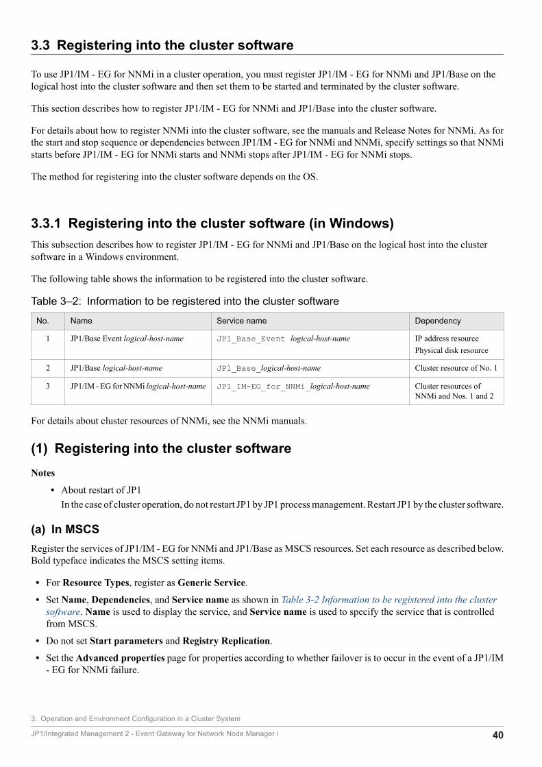
The following table shows the information to be registered into the cluster software.
Table 3‒2: Information to be registered into the cluster software
No. Name Service name Dependency
1 JP1/Base Event logical-host-name JP1_Base_Event logical-host-name IP address resourcePhysical disk resource
2 JP1/Base logical-host-name JP1_Base_logical-host-name Cluster resource of No. 1
3 JP1/IM - EG for NNMi logical-host-name JP1_IM-EG_for_NNMi_logical-host-name Cluster resources ofNNMi and Nos. 1 and 2
For details about cluster resources of NNMi, see the NNMi manuals.
(1) Registering into the cluster softwareNotes
• About restart of JP1In the case of cluster operation, do not restart JP1 by JP1 process management. Restart JP1 by the cluster software.
(a) In MSCSRegister the services of JP1/IM - EG for NNMi and JP1/Base as MSCS resources. Set each resource as described below.Bold typeface indicates the MSCS setting items.
• For Resource Types, register as Generic Service.
• Set Name, Dependencies, and Service name as shown in Table 3-2 Information to be registered into the clustersoftware. Name is used to display the service, and Service name is used to specify the service that is controlledfrom MSCS.
• Do not set Start parameters and Registry Replication.
• Set the Advanced properties page for properties according to whether failover is to occur in the event of a JP1/IM- EG for NNMi failure.
3. Operation and Environment Configuration in a Cluster System
JP1/Integrated Management 2 - Event Gateway for Network Node Manager i 40
For example, to set failover to occur in the event of a JP1/IM - EG for NNMi failure, select the Restart and Affectthe group check boxes and specify Threshold for the restart retry count, using a value of 3 (times) as a guideline.
(b) When registering the service start and stop commandsRegister into the cluster software the services of JP1/IM - EG for NNMi and JP1/Base to be started and stopped. Forexample, specify the settings so that the services shown in the Name column in Table 3-2 Information to be registeredinto the cluster software are to be started and stopped by the net command.
You can use the following commands to check the operation of JP1/IM - EG for NNMi and JP1/Base:
• jegn_spmd_statusChecks the operation of JP1/IM - EG for NNMi.
• jbs_spmd_statusChecks the operation of JP1/Base.
• jevstatChecks the operation of the JP1/Base event service.
For details about the jegn_spmd_status command, see jegn_spmd_status in 7. Commands. For details about thejbs_spmd_status and jevstat commands, see the JP1/Base User's Guide.
(2) Setting the resource start and stop sequenceTo execute JP1/IM - EG for NNMi and JP1/Base on the logical host, the shared disk and logical IP address must beavailable for use.
Set the start and stop sequence or dependencies in such a manner that they are controlled by the cluster software asdescribed below.
• When the logical host starts
1. Allocate the shared disk and logical IP address and make them available for use.
2. Start JP1/Base, NNMi and JP1/IM - EG for NNMi, in this order.
• When the logical host terminates
1. Terminate JP1/IM - EG for NNMi, NNMi and JP1/Base, in this order.
2. Release allocation of the shared disk and logical IP address.
3.3.2 Registering into the cluster software (in UNIX)This subsection describes how to register JP1/IM - EG for NNMi and JP1/Base on the logical host into the clustersoftware in a UNIX environment.
(1) Creating scripts to be registered into the cluster softwareWhen you use UNIX cluster software, you normally create a tool to control applications by a method such as scriptsand then you register the scripts into the cluster software. In general, you need scripts to provide the Start, Stop, Operationmonitoring, and Forced stop functions.
3. Operation and Environment Configuration in a Cluster System
JP1/Integrated Management 2 - Event Gateway for Network Node Manager i 41
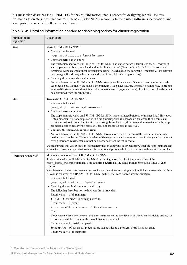
This subsection describes the JP1/IM - EG for NNMi information that is needed for designing scripts. Use thisinformation to create scripts that control JP1/IM - EG for NNMi according to the cluster software specifications andthen register the scripts into the cluster software.
Table 3‒3: Detailed information needed for designing scripts for cluster registration
Function to beregistered
Description
Start Starts JP1/IM - EG for NNMi.• Command to be usedjegn_start.cluster logical-host-name
• Command termination timingThe start command waits until JP1/IM - EG for NNMi has started before it terminates itself. However, ifstartup processing is not completed within the timeout period (60 seconds is the default), the commandterminates without completing the startup processing. In such a case, the command terminates with the startupprocessing still underway (the command does not cancel the startup processing).
• Checking the command execution resultYou can determine the JP1/IM - EG for NNMi startup result by means of the operation monitoring methoddescribed below. Normally, the result is determined by the cluster software's operation monitoring. The returnvalues of the start command are 0 (normal termination) and 1 (argument error); therefore, result details cannotbe determined from the return value.
Stop Terminates JP1/IM - EG for NNMi.• Command to be usedjegn_stop.cluster logical-host-name
• Command termination timingThe stop command waits until JP1/IM - EG for NNMi has terminated before it terminates itself. However,if stop processing is not completed within the timeout period (60 seconds is the default), the commandterminates without completing the stop processing. In such a case, the command terminates with the stopprocessing still underway (the command does not cancel the stop processing).
• Checking the command execution resultYou can determine the JP1/IM - EG for NNMi termination result by means of the operation monitoringmethod described below. The return values of the stop command are 0 (normal termination) and 1 (argumenterror); therefore, result details cannot be determined from the return value.
We recommend that you execute the forced termination command described below after the stop command hasterminated. This enables you to terminate the process and prevent a failover error even in the event of a problem.
Operation monitoring# Monitors normal operation of JP1/IM - EG for NNMi.To determine whether JP1/IM - EG for NNMi is running normally, check the return value of thejegn_spmd_status command. This command determines the status from the operating status of eachprocess.Note that some cluster software does not provide the operation monitoring function. If there is no need to performfailover in the event of a JP1/IM - EG for NNMi failure, you need not register this function.• Command to be usedjegn_spmd_status -h logical-host-name
• Checking the result of operation monitoringThe following describes how to interpret the return value:Return value = 0 (all running):JP1/IM - EG for NNMi is running normally.Return value = 1 (error):An unrecoverable error has occurred. Treat this as an error.Note:If you execute the jegn_spmd_status command on the standby server whose shared disk is offline, thereturn value will be 1 because the shared disk is not available.Return value = 4 (partially stopped):Some JP1/IM - EG for NNMi processes are stopped due to a problem. Treat this as an error.Return value = 8 (all stopped):
3. Operation and Environment Configuration in a Cluster System
JP1/Integrated Management 2 - Event Gateway for Network Node Manager i 42
Function to beregistered
Description
Operation monitoring# The JP1/IM - EG for NNMi processes have all stopped due to a problem. Treat this as an error.Return value = 12 (retriable error):While the jegn_spmd_status command was checking the operating status, an error that can be recoveredby retries has occurred. Retry checking of the operating status as many times as specified.
Forced stop Forcibly terminates JP1/IM - EG for NNMi and releases the current resources.• Command to be used
The jegn_killall.cluster command forcibly terminates each process without performing JP1/IM -EG for NNMi termination processing.
Note:Before you execute forced stop, use the stop command to terminate JP1/IM - EG for NNMi.
#With respect to JP1 operation checking, the same commands are used in both UNIX and Windows, but they function differently.Windows operation differs from UNIX operation due to its association with Windows service control. In Windows, when any processterminates, JP1 process management automatically terminates all processes and places the service in stopped status. Assume such a servicestop is the result of an error or assume an error has occurred when a command such as jegn_spmd_status returns a value of 8.
About restart of JP1In the case of cluster operation, do not restart JP1 by JP1 process management. Restart JP1 by the cluster software.
(2) Setting the resource start and stop sequenceTo execute JP1/IM - EG for NNMi and JP1/Base on the logical host, the shared disk and logical IP address must beavailable for use.
Set the start and stop sequence or dependencies in such a manner that they are controlled by the cluster software asdescribed below.
• When the logical host starts
1. Allocate the shared disk and logical IP address and make them available for use.
2. Start JP1/Base, NNMi and JP1/IM - EG for NNMi, in this order.
• When the logical host terminates
1. Terminate JP1/IM - EG for NNMi, NNMi and JP1/Base, in this order.
2. Release allocation of the shared disk and logical IP address.
3. Operation and Environment Configuration in a Cluster System
JP1/Integrated Management 2 - Event Gateway for Network Node Manager i 43
3.4 Deleting the logical host
This subsection describes how to delete the logical host. The logical host deletion procedure depends on the OS.
In WindowsUse the jp1bshasetup command of JP1/Base.
To delete the logical host:
1. Execute jp1bshasetup.exe.
2. In the Settings for Base Node Switching System window, click the Delete Logical Host button.
3. Select the name of the logical host that you want to delete.
4. Click the Next button.
5. Check that the deletion details are correct and click the Finish button.
In UNIXUse the jbsunsetcnf command of JP1/Base. Execute the following command:
/opt/jp1base/bin/jbsunsetcnf -i -h logical-host-name
Note that when you delete the logical host, the logical hosts for JP1/Base and for those products that require JP1/Baseare also deleted in the batch mode. When you delete only JP1/IM - EG for NNMi from a logical host, you must executethe following commands to delete common definitions on the primary node and the secondary node.
• [logical-host-name\JP1EG4NNMI\] keyjbsunsetcnf -h logical-host-name -c JP1EG4NNMI
Shared files (shared folders) on the shared disk are not deleted; you must delete them manually.
For details about the jp1bshasetup and jbsunsetcnf commands, see the JP1/Base User's Guide.
3. Operation and Environment Configuration in a Cluster System
JP1/Integrated Management 2 - Event Gateway for Network Node Manager i 44
3.5 Notes about cluster operation
The notes in this section apply to cluster operation.
• If you run multiple logical hosts concurrently in a cluster system, you need as many system resources as there arelogical hosts running concurrently.
• If node switching occurs while a JP1 event is being issued, duplicate JP1 events might be registered.
• Before you uninstall JP1/IM - EG for NNMi in a cluster system, first delete the logical host.For details, see 3.4 Deleting the logical host.
3. Operation and Environment Configuration in a Cluster System
JP1/Integrated Management 2 - Event Gateway for Network Node Manager i 45
4 Converting NNMi Incidents into JP1 Events
This chapter describes the settings in the definition files that are used to convert NNMi incidentsinto JP1 events.
JP1/Integrated Management 2 - Event Gateway for Network Node Manager i 46

4.1 Creating an NNMi incident forwarding filter definition file
The NNMi incident forwarding filter definition file is used to specify conditions for converting NNMi incidents acquiredfrom NNMi into JP1 events. This file defines the following information:
• Conditions for determining the NNMi incidents that are to be converted into JP1 events (filter conditions)
• Correspondences between NNMi incident attributes and JP1 event attributes (mapping conditions)
Only those NNMi incidents that satisfy the filter conditions are converted into JP1 events according to the specifiedmapping conditions and then registered into the event database of JP1/Base.
Creating an NNMi incident forwarding filter definition fileThere is no NNMi incident forwarding filter definition file at the time of installation. You must copy the samplefile, rename it, and then edit the sample definitions in the file. If you do not create an NNMi incident forwardingfilter definition file, NNMi incidents will not be converted into JP1 events.
The name and storage location of the sample NNMi incident forwarding filter definition file are shown below.
File nameimevtgw_nnmi_forward_filter.confimevtgw_nnmi_forward_filter.conf.sample (sample file)
Storage location
In Windows:
• Physical host: E-for-NNMi-path\conf• Logical host: shared-folder\JP1EG4NNMI\conf
In UNIX:
• Physical host: /etc/opt/jp1eg4nnmi/conf• Logical host: shared-directory/jp1eg4nnmi/conf
NoteEach attribute value of an NNMi incident converted to a JP1 event reflects the value at the time that JP1/IM - EGfor NNMi obtained the NNMi incident. Keep in mind that if any NNMi incident information is updated after theincident is converted to a JP1 event, the updated information will not be reflected with the JP1 event.
4.1.1 Format of the NNMi incident forwarding filter definition fileThe NNMi incident forwarding filter definition file consists of the following two blocks:
• Filter condition blockThis block specifies conditions for the NNMi incidents that are to be converted into JP1 events (filter conditions).Specification of a filter condition block is mandatory.
• Mapping blockThis block specifies correspondences between NNMi incident attributes and JP1 event attributes (mappingconditions). Specification of a mapping block is optional.
The filter condition block and the mapping block constitute a forwarding condition block. When multiple forwardingcondition blocks are specified in the NNMi incident forwarding filter definition file, comparison processing is performed
4. Converting NNMi Incidents into JP1 Events
JP1/Integrated Management 2 - Event Gateway for Network Node Manager i 47
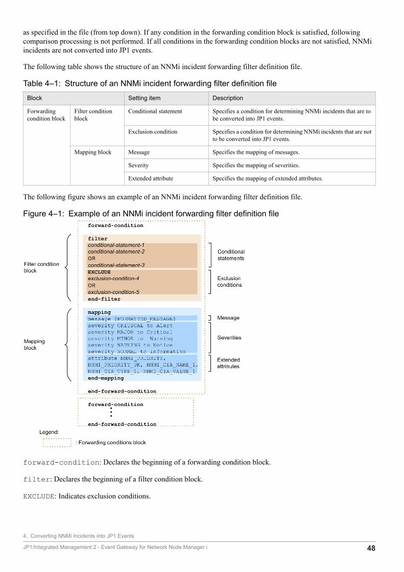
as specified in the file (from top down). If any condition in the forwarding condition block is satisfied, followingcomparison processing is not performed. If all conditions in the forwarding condition blocks are not satisfied, NNMiincidents are not converted into JP1 events.
The following table shows the structure of an NNMi incident forwarding filter definition file.
Table 4‒1: Structure of an NNMi incident forwarding filter definition file
Block Setting item Description
Forwardingcondition block
Filter conditionblock
Conditional statement Specifies a condition for determining NNMi incidents that are tobe converted into JP1 events.
Exclusion condition Specifies a condition for determining NNMi incidents that are notto be converted into JP1 events.
Mapping block Message Specifies the mapping of messages.
Severity Specifies the mapping of severities.
Extended attribute Specifies the mapping of extended attributes.
The following figure shows an example of an NNMi incident forwarding filter definition file.
Figure 4‒1: Example of an NNMi incident forwarding filter definition file
forward-condition: Declares the beginning of a forwarding condition block.
filter: Declares the beginning of a filter condition block.
EXCLUDE: Indicates exclusion conditions.
4. Converting NNMi Incidents into JP1 Events
JP1/Integrated Management 2 - Event Gateway for Network Node Manager i 48
end-filter: Declares the end of a filter condition block.
mapping: Declares the beginning of a mapping block.
end-mapping: Declares the end of a mapping block.
end-forward-condition: Declares the end of a forwarding condition block.
Rules for the NNMi incident forwarding filter definition fileThe following rules apply to the NNMi incident forwarding filter definition file:
• The maximum size of the NNMi incident forwarding filter definition file is 10 megabytes.
• You can specify a maximum of 100 forwarding condition blocks.
• Do not specify multiple filter condition blocks or mapping blocks in a single forwarding condition block. Anerror results if one forwarding condition block contains multiple filter condition blocks or multiple mappingblocks.
• You can specify multiple conditions by using OR to link multiple conditional statements or exclusion conditions.
• Specify each message or extended attribute mapping setting on a single line without inserting a linefeed code.
• A line beginning with a hash mark (#) is treated as a comment line.
4.1.2 Defining a filter condition blockA filter condition block specifies filtering conditional statements for the NNMi incidents that are to be converted intoJP1 events. The filtering conditional statements consist of conditional statements and exclusion conditions. Specificationof a filter condition block is mandatory.
(1) Format of a filter condition blockSpecify a filter condition block in the following format:
attribute-nameΔoperatorΔoperand-1Δoperand-2Δ...
Δ indicates one or more consecutive spaces or tabs.
• attribute-nameSpecifies an attribute name of NNMi incidents.
• operatorSpecifies a condition for filtering the NNMi incidents.
• operandSpecifies a value for filtering the NNMi incidents.
When the attribute value corresponding to the attribute name is compared with the value specified in the operand in acase sensitive manner, if the operator condition is satisfied, the filter condition is established.
For example, if you want to convert into JP1 events those NNMi incidents whose name (NAME) is SNMPLinkDown,specify the following filtering conditional statement:
NAME IN SNMPLinkDown
4. Converting NNMi Incidents into JP1 Events
JP1/Integrated Management 2 - Event Gateway for Network Node Manager i 49
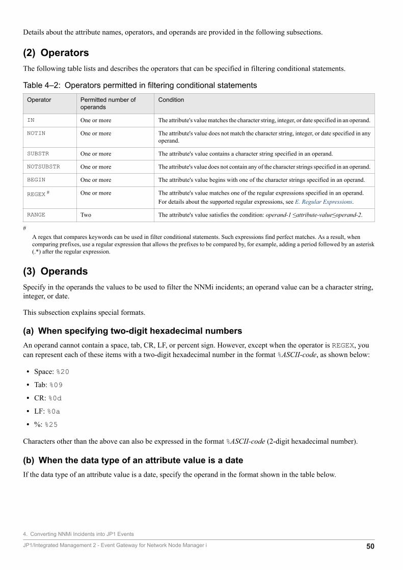
Details about the attribute names, operators, and operands are provided in the following subsections.
(2) OperatorsThe following table lists and describes the operators that can be specified in filtering conditional statements.
Table 4‒2: Operators permitted in filtering conditional statements
Operator Permitted number ofoperands
Condition
IN One or more The attribute's value matches the character string, integer, or date specified in an operand.
NOTIN One or more The attribute's value does not match the character string, integer, or date specified in anyoperand.
SUBSTR One or more The attribute's value contains a character string specified in an operand.
NOTSUBSTR One or more The attribute's value does not contain any of the character strings specified in an operand.
BEGIN One or more The attribute's value begins with one of the character strings specified in an operand.
REGEX # One or more The attribute's value matches one of the regular expressions specified in an operand.For details about the supported regular expressions, see E. Regular Expressions.
RANGE Two The attribute's value satisfies the condition: operand-1 ≤attribute-value≤operand-2.
#A regex that compares keywords can be used in filter conditional statements. Such expressions find perfect matches. As a result, whencomparing prefixes, use a regular expression that allows the prefixes to be compared by, for example, adding a period followed by an asterisk(.*) after the regular expression.
(3) OperandsSpecify in the operands the values to be used to filter the NNMi incidents; an operand value can be a character string,integer, or date.
This subsection explains special formats.
(a) When specifying two-digit hexadecimal numbersAn operand cannot contain a space, tab, CR, LF, or percent sign. However, except when the operator is REGEX, youcan represent each of these items with a two-digit hexadecimal number in the format %ASCII-code, as shown below:
• Space: %20• Tab: %09• CR: %0d• LF: %0a• %: %25
Characters other than the above can also be expressed in the format %ASCII-code (2-digit hexadecimal number).
(b) When the data type of an attribute value is a dateIf the data type of an attribute value is a date, specify the operand in the format shown in the table below.
4. Converting NNMi Incidents into JP1 Events
JP1/Integrated Management 2 - Event Gateway for Network Node Manager i 50
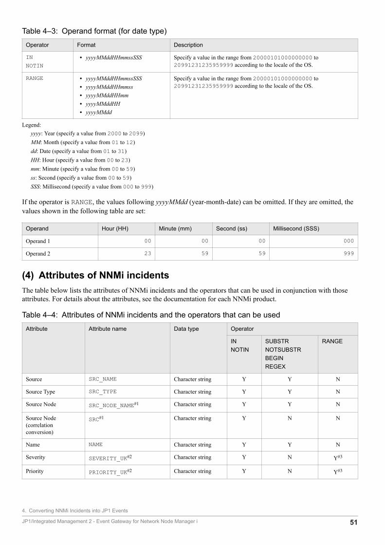
Table 4‒3: Operand format (for date type)
Operator Format Description
INNOTIN
• yyyyMMddHHmmssSSS Specify a value in the range from 20000101000000000 to20991231235959999 according to the locale of the OS.
RANGE • yyyyMMddHHmmssSSS• yyyyMMddHHmmss• yyyyMMddHHmm• yyyyMMddHH• yyyyMMdd
Specify a value in the range from 20000101000000000 to20991231235959999 according to the locale of the OS.
Legend:yyyy: Year (specify a value from 2000 to 2099)MM: Month (specify a value from 01 to 12)dd: Date (specify a value from 01 to 31)HH: Hour (specify a value from 00 to 23)mm: Minute (specify a value from 00 to 59)ss: Second (specify a value from 00 to 59)SSS: Millisecond (specify a value from 000 to 999)
If the operator is RANGE, the values following yyyyMMdd (year-month-date) can be omitted. If they are omitted, thevalues shown in the following table are set:
Operand Hour (HH) Minute (mm) Second (ss) Millisecond (SSS)
Operand 1 00 00 00 000
Operand 2 23 59 59 999
(4) Attributes of NNMi incidentsThe table below lists the attributes of NNMi incidents and the operators that can be used in conjunction with thoseattributes. For details about the attributes, see the documentation for each NNMi product.
Table 4‒4: Attributes of NNMi incidents and the operators that can be used
Attribute Attribute name Data type Operator
INNOTIN
SUBSTRNOTSUBSTRBEGINREGEX
RANGE
Source SRC_NAME Character string Y Y N
Source Type SRC_TYPE Character string Y Y N
Source Node SRC_NODE_NAME#1 Character string Y Y N
Source Node(correlationconversion)
SRC#1 Character string Y N N
Name NAME Character string Y Y N
Severity SEVERITY_UK#2 Character string Y N Y#3
Priority PRIORITY_UK#2 Character string Y N Y#3
4. Converting NNMi Incidents into JP1 Events
JP1/Integrated Management 2 - Event Gateway for Network Node Manager i 51
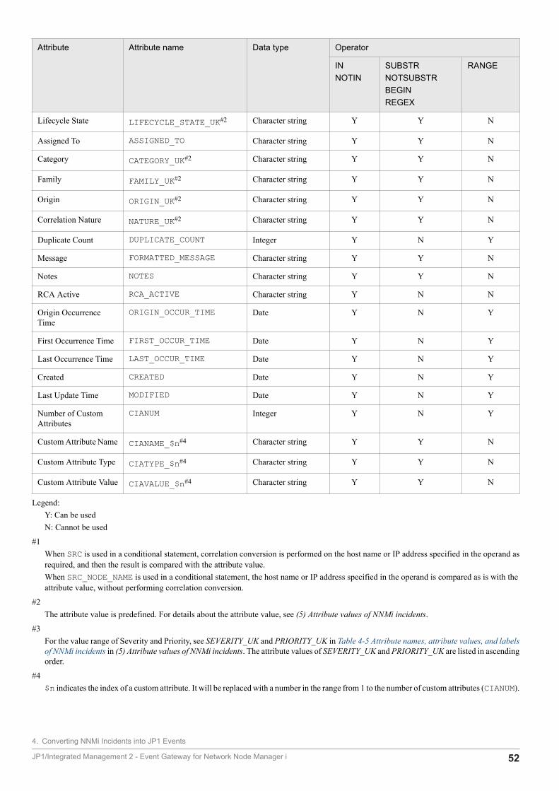
Attribute Attribute name Data type Operator
INNOTIN
SUBSTRNOTSUBSTRBEGINREGEX
RANGE
Lifecycle State LIFECYCLE_STATE_UK#2 Character string Y Y N
Assigned To ASSIGNED_TO Character string Y Y N
Category CATEGORY_UK#2 Character string Y Y N
Family FAMILY_UK#2 Character string Y Y N
Origin ORIGIN_UK#2 Character string Y Y N
Correlation Nature NATURE_UK#2 Character string Y Y N
Duplicate Count DUPLICATE_COUNT Integer Y N Y
Message FORMATTED_MESSAGE Character string Y Y N
Notes NOTES Character string Y Y N
RCA Active RCA_ACTIVE Character string Y N N
Origin OccurrenceTime
ORIGIN_OCCUR_TIME Date Y N Y
First Occurrence Time FIRST_OCCUR_TIME Date Y N Y
Last Occurrence Time LAST_OCCUR_TIME Date Y N Y
Created CREATED Date Y N Y
Last Update Time MODIFIED Date Y N Y
Number of CustomAttributes
CIANUM Integer Y N Y
Custom Attribute Name CIANAME_$n#4 Character string Y Y N
Custom Attribute Type CIATYPE_$n#4 Character string Y Y N
Custom Attribute Value CIAVALUE_$n#4 Character string Y Y N
Legend:Y: Can be usedN: Cannot be used
#1When SRC is used in a conditional statement, correlation conversion is performed on the host name or IP address specified in the operand asrequired, and then the result is compared with the attribute value.When SRC_NODE_NAME is used in a conditional statement, the host name or IP address specified in the operand is compared as is with theattribute value, without performing correlation conversion.
#2The attribute value is predefined. For details about the attribute value, see (5) Attribute values of NNMi incidents.
#3For the value range of Severity and Priority, see SEVERITY_UK and PRIORITY_UK in Table 4-5 Attribute names, attribute values, and labelsof NNMi incidents in (5) Attribute values of NNMi incidents. The attribute values of SEVERITY_UK and PRIORITY_UK are listed in ascendingorder.
#4$n indicates the index of a custom attribute. It will be replaced with a number in the range from 1 to the number of custom attributes (CIANUM).
4. Converting NNMi Incidents into JP1 Events
JP1/Integrated Management 2 - Event Gateway for Network Node Manager i 52
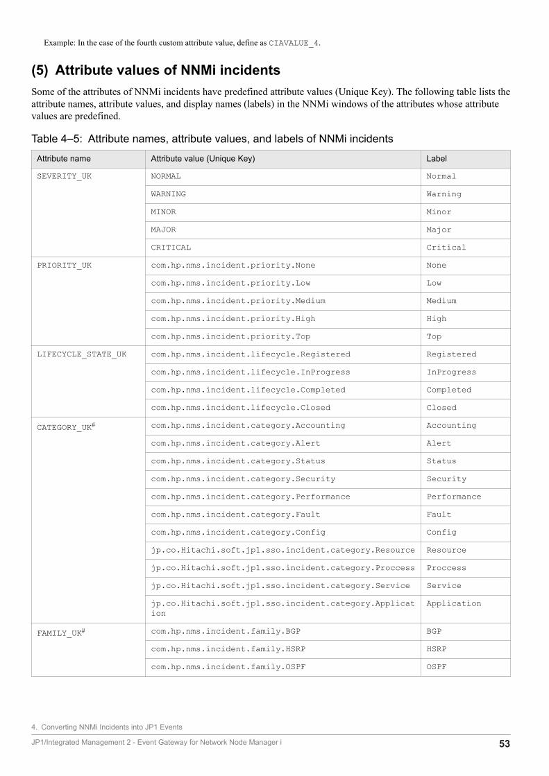
Example: In the case of the fourth custom attribute value, define as CIAVALUE_4.
(5) Attribute values of NNMi incidentsSome of the attributes of NNMi incidents have predefined attribute values (Unique Key). The following table lists theattribute names, attribute values, and display names (labels) in the NNMi windows of the attributes whose attributevalues are predefined.
Table 4‒5: Attribute names, attribute values, and labels of NNMi incidents
Attribute name Attribute value (Unique Key) Label
SEVERITY_UK NORMAL Normal
WARNING Warning
MINOR Minor
MAJOR Major
CRITICAL Critical
PRIORITY_UK com.hp.nms.incident.priority.None None
com.hp.nms.incident.priority.Low Low
com.hp.nms.incident.priority.Medium Medium
com.hp.nms.incident.priority.High High
com.hp.nms.incident.priority.Top Top
LIFECYCLE_STATE_UK com.hp.nms.incident.lifecycle.Registered Registered
com.hp.nms.incident.lifecycle.InProgress InProgress
com.hp.nms.incident.lifecycle.Completed Completed
com.hp.nms.incident.lifecycle.Closed Closed
CATEGORY_UK# com.hp.nms.incident.category.Accounting Accounting
com.hp.nms.incident.category.Alert Alert
com.hp.nms.incident.category.Status Status
com.hp.nms.incident.category.Security Security
com.hp.nms.incident.category.Performance Performance
com.hp.nms.incident.category.Fault Fault
com.hp.nms.incident.category.Config Config
jp.co.Hitachi.soft.jp1.sso.incident.category.Resource Resource
jp.co.Hitachi.soft.jp1.sso.incident.category.Proccess Proccess
jp.co.Hitachi.soft.jp1.sso.incident.category.Service Service
jp.co.Hitachi.soft.jp1.sso.incident.category.Application
Application
FAMILY_UK# com.hp.nms.incident.family.BGP BGP
com.hp.nms.incident.family.HSRP HSRP
com.hp.nms.incident.family.OSPF OSPF
4. Converting NNMi Incidents into JP1 Events
JP1/Integrated Management 2 - Event Gateway for Network Node Manager i 53
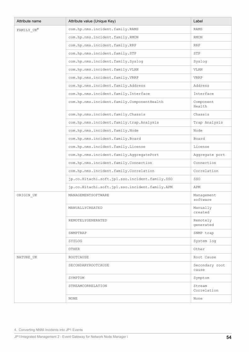
Attribute name Attribute value (Unique Key) Label
FAMILY_UK# com.hp.nms.incident.family.RAMS RAMS
com.hp.nms.incident.family.RMON RMON
com.hp.nms.incident.family.RRP RRP
com.hp.nms.incident.family.STP STP
com.hp.nms.incident.family.Syslog Syslog
com.hp.nms.incident.family.VLAN VLAN
com.hp.nms.incident.family.VRRP VRRP
com.hp.nms.incident.family.Address Address
com.hp.nms.incident.family.Interface Interface
com.hp.nms.incident.family.ComponentHealth ComponentHealth
com.hp.nms.incident.family.Chassis Chassis
com.hp.nms.incident.family.trap.Analysis Trap Analysis
com.hp.nms.incident.family.Node Node
com.hp.nms.incident.family.Board Board
com.hp.nms.incident.family.License License
com.hp.nms.incident.family.AggregatePort Aggregate port
com.hp.nms.incident.family.Connection Connection
com.hp.nms.incident.family.Correlation Correlation
jp.co.Hitachi.soft.jp1.sso.incident.family.SSO SSO
jp.co.Hitachi.soft.jp1.sso.incident.family.APM APM
ORIGIN_UK MANAGEMENTSOFTWARE Managementsoftware
MANUALLYCREATED Manuallycreated
REMOTELYGENERATED Remotelygenerated
SNMPTRAP SNMP trap
SYSLOG System log
OTHER Other
NATURE_UK ROOTCAUSE Root Cause
SECONDARYROOTCAUSE Secondary rootcause
SYMPTOM Symptom
STREAMCORRELATION StreamCorrelation
NONE None
4. Converting NNMi Incidents into JP1 Events
JP1/Integrated Management 2 - Event Gateway for Network Node Manager i 54
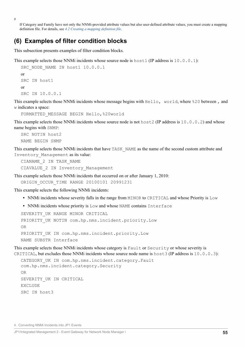
#If Category and Family have not only the NNMi-provided attribute values but also user-defined attribute values, you must create a mappingdefinition file. For details, see 4.2 Creating a mapping definition file.
(6) Examples of filter condition blocksThis subsection presents examples of filter condition blocks.
This example selects those NNMi incidents whose source node is host1 (IP address is 10.0.0.1):SRC_NODE_NAME IN host1 10.0.0.1orSRC IN host1orSRC IN 10.0.0.1
This example selects those NNMi incidents whose message begins with Hello, world, where %20 between , andw indicates a space:
FORMATTED_MESSAGE BEGIN Hello,%20worldThis example selects those NNMi incidents whose source node is not host2 (IP address is 10.0.0.2) and whosename begins with SNMP:
SRC NOTIN host2NAME BEGIN SNMP
This example selects those NNMi incidents that have TASK_NAME as the name of the second custom attribute andInventory_Management as its value:
CIANAME_2 IN TASK_NAMECIAVALUE_2 IN Inventory_Management
This example selects those NNMi incidents that occurred on or after January 1, 2010:ORIGIN_OCCUR_TIME RANGE 20100101 20991231
This example selects the following NNMi incidents:
• NNMi incidents whose severity falls in the range from MINOR to CRITICAL and whose Priority is Low• NNMi incidents whose priority is Low and whose NAME contains InterfaceSEVERITY_UK RANGE MINOR CRITICALPRIORITY_UK NOTIN com.hp.nms.incident.priority.LowORPRIORITY_UK IN com.hp.nms.incident.priority.LowNAME SUBSTR Interface
This example selects those NNMi incidents whose category is Fault or Security or whose severity isCRITICAL, but excludes those NNMi incidents whose source node name is host3 (IP address is 10.0.0.3):
CATEGORY_UK IN com.hp.nms.incident.category.Faultcom.hp.nms.incident.category.SecurityORSEVERITY_UK IN CRITICALEXCLUDESRC IN host3
4. Converting NNMi Incidents into JP1 Events
JP1/Integrated Management 2 - Event Gateway for Network Node Manager i 55
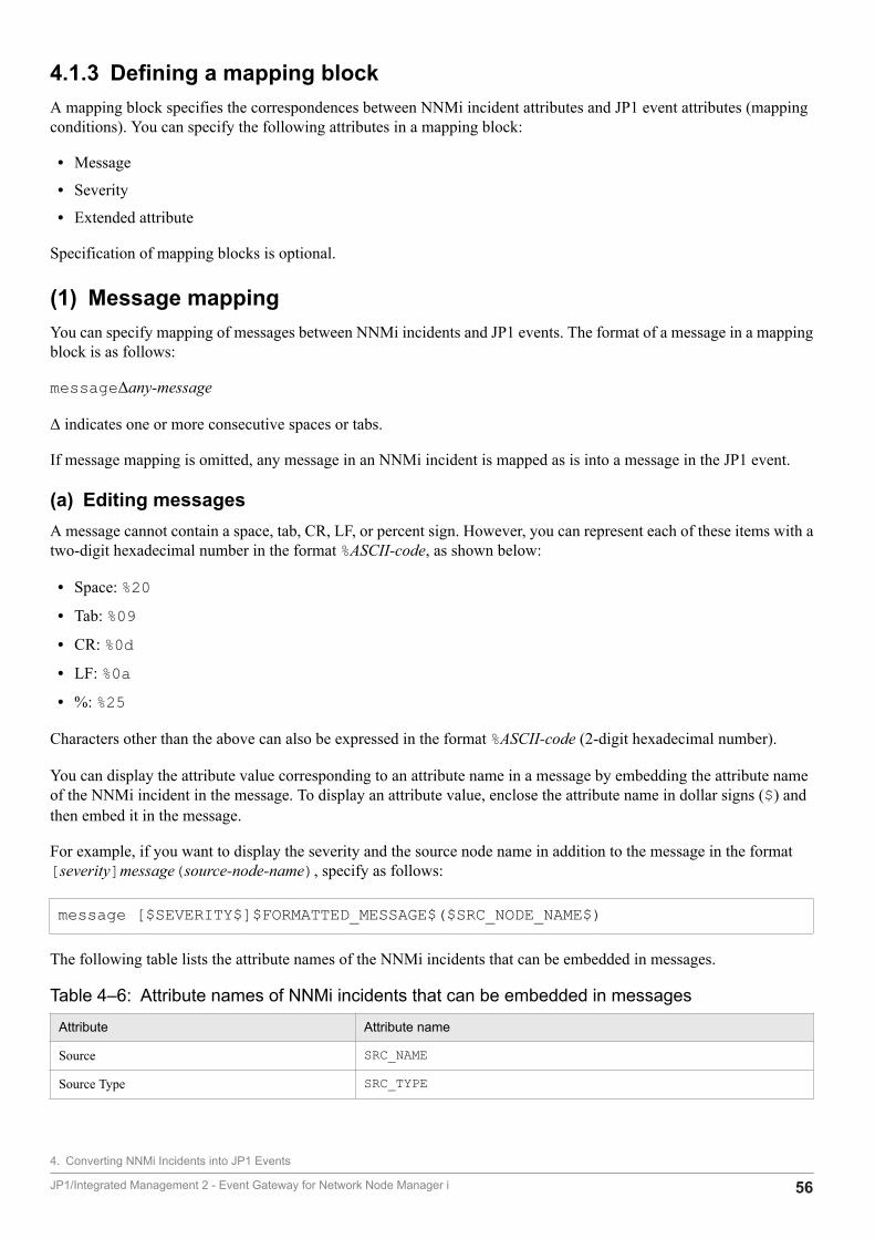
4.1.3 Defining a mapping blockA mapping block specifies the correspondences between NNMi incident attributes and JP1 event attributes (mappingconditions). You can specify the following attributes in a mapping block:
• Message
• Severity
• Extended attribute
Specification of mapping blocks is optional.
(1) Message mappingYou can specify mapping of messages between NNMi incidents and JP1 events. The format of a message in a mappingblock is as follows:
messageΔany-message
Δ indicates one or more consecutive spaces or tabs.
If message mapping is omitted, any message in an NNMi incident is mapped as is into a message in the JP1 event.
(a) Editing messagesA message cannot contain a space, tab, CR, LF, or percent sign. However, you can represent each of these items with atwo-digit hexadecimal number in the format %ASCII-code, as shown below:
• Space: %20• Tab: %09• CR: %0d• LF: %0a• %: %25
Characters other than the above can also be expressed in the format %ASCII-code (2-digit hexadecimal number).
You can display the attribute value corresponding to an attribute name in a message by embedding the attribute nameof the NNMi incident in the message. To display an attribute value, enclose the attribute name in dollar signs ($) andthen embed it in the message.
For example, if you want to display the severity and the source node name in addition to the message in the format[severity]message(source-node-name), specify as follows:
message [$SEVERITY$]$FORMATTED_MESSAGE$($SRC_NODE_NAME$)
The following table lists the attribute names of the NNMi incidents that can be embedded in messages.
Table 4‒6: Attribute names of NNMi incidents that can be embedded in messages
Attribute Attribute name
Source SRC_NAME
Source Type SRC_TYPE
4. Converting NNMi Incidents into JP1 Events
JP1/Integrated Management 2 - Event Gateway for Network Node Manager i 56
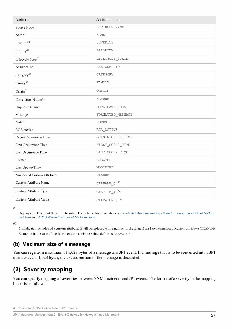
Attribute Attribute name
Source Node SRC_NODE_NAME
Name NAME
Severity#1 SEVERITY
Priority#1 PRIORITY
Lifecycle State#1 LIFECYCLE_STATE
Assigned To ASSIGNED_TO
Category#1 CATEGORY
Family#1 FAMILY
Origin#1 ORIGIN
Correlation Nature#1 NATURE
Duplicate Count DUPLICATE_COUNT
Message FORMATTED_MESSAGE
Notes NOTES
RCA Active RCA_ACTIVE
Origin Occurrence Time ORIGIN_OCCUR_TIME
First Occurrence Time FIRST_OCCUR_TIME
Last Occurrence Time LAST_OCCUR_TIME
Created CREATED
Last Update Time MODIFIED
Number of Custom Attributes CIANUM
Custom Attribute Name CIANAME_$n#2
Custom Attribute Type CIATYPE_$n#2
Custom Attribute Value CIAVALUE_$n#2
#1Displays the label, not the attribute value. For details about the labels, see Table 4-5 Attribute names, attribute values, and labels of NNMiincidents in 4.1.2(5) Attribute values of NNMi incidents.
#2$n indicates the index of a custom attribute. It will be replaced with a number in the range from 1 to the number of custom attributes (CIANUM).Example: In the case of the fourth custom attribute value, define as CIAVALUE_4.
(b) Maximum size of a messageYou can register a maximum of 1,023 bytes of a message as a JP1 event. If a message that is to be converted into a JP1event exceeds 1,023 bytes, the excess portion of the message is discarded.
(2) Severity mappingYou can specify mapping of severities between NNMi incidents and JP1 events. The format of a severity in the mappingblock is as follows:
4. Converting NNMi Incidents into JP1 Events
JP1/Integrated Management 2 - Event Gateway for Network Node Manager i 57
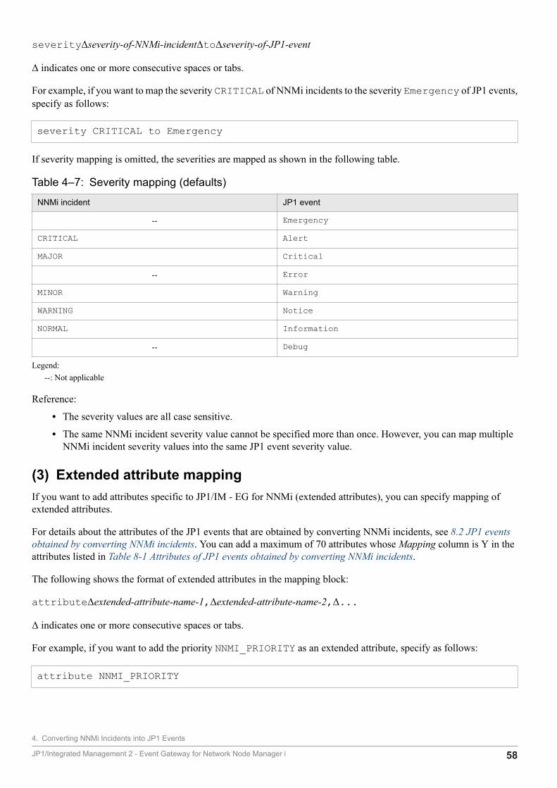
severityΔseverity-of-NNMi-incidentΔtoΔseverity-of-JP1-event
Δ indicates one or more consecutive spaces or tabs.
For example, if you want to map the severity CRITICAL of NNMi incidents to the severity Emergency of JP1 events,specify as follows:
severity CRITICAL to Emergency
If severity mapping is omitted, the severities are mapped as shown in the following table.
Table 4‒7: Severity mapping (defaults)
NNMi incident JP1 event
-- Emergency
CRITICAL Alert
MAJOR Critical
-- Error
MINOR Warning
WARNING Notice
NORMAL Information
-- Debug
Legend:--: Not applicable
Reference:
• The severity values are all case sensitive.
• The same NNMi incident severity value cannot be specified more than once. However, you can map multipleNNMi incident severity values into the same JP1 event severity value.
(3) Extended attribute mappingIf you want to add attributes specific to JP1/IM - EG for NNMi (extended attributes), you can specify mapping ofextended attributes.
For details about the attributes of the JP1 events that are obtained by converting NNMi incidents, see 8.2 JP1 eventsobtained by converting NNMi incidents. You can add a maximum of 70 attributes whose Mapping column is Y in theattributes listed in Table 8-1 Attributes of JP1 events obtained by converting NNMi incidents.
The following shows the format of extended attributes in the mapping block:
attributeΔextended-attribute-name-1,Δextended-attribute-name-2,Δ...
Δ indicates one or more consecutive spaces or tabs.
For example, if you want to add the priority NNMI_PRIORITY as an extended attribute, specify as follows:
attribute NNMI_PRIORITY
4. Converting NNMi Incidents into JP1 Events
JP1/Integrated Management 2 - Event Gateway for Network Node Manager i 58

If you omit mapping of extended attributes, extended attributes cannot be added.
(a) Total size of extended attributesThe maximum total size of the extended attributes that can be added is 10,000 bytes. Any extended attributes beyondbyte 10,000 are not mapped. Therefore, select the extended attributes to be added so that their total size does not exceed10,000 bytes.
You can use the following formula to determine the size of one extended attribute:
Size of extended attribute = Length of attribute name in characters + 1 + size of attribute value
For details about the sizes of attribute values, see Table 8-1 Attributes of JP1 events obtained by converting NNMiincidents. We recommend that you estimate the size of attribute values based on the maximum size. If the size is fixedor the maximum size is known, use that size.
Example:The size of the priority (NNMI_PRIORITY) extended attribute is determined as follows:269 = 13 (length of attribute name in characters) + 1 + 255 (maximum size of attribute value)For example, if it is known that only those NNMi incidents whose priority attribute values are the highest(com.hp.nms.incident.priority.Top) are to be converted into JP1 events, you can use 32 as the size ofthe attribute value.
(b) Checking the result of extended attribute mappingYou can determine the result of extended attribute mapping by checking the attribute value of the NNMI_EM_RESULTextended attribute. The following explains the attribute values of the NNMI_EM_RESULT extended attribute:
ALLIndicates that all the specified attributes have been added as JP1 event extended attributes. The result is also shownas ALL when there are no attributes to be added (extended attribute mapping has been omitted).
numeric-valueIndicates the number of attributes that have been added as JP1 event extended attributes. For example, if you issueda JP1 event with 10 attributes specified in the mapping block, and the attribute value of the NNMI_EM_RESULTextended attribute is 8, then the last two attributes specified in the mapping block were not added.
4.1.4 Definition example (sample file)This subsection describes a definition example of an NNMi incident forwarding filter definition file based on using thesample file.
Shown below are the contents of the sample file. Note that line numbers are added for explanation purposes.
1 forward-condition2 filter3 #An incident whose severity level is MINOR or higher4 SEVERITY_UK RANGE MINOR CRITICAL5 end-filter6 mapping7 message $FORMATTED_MESSAGE$8 severity CRITICAL to Alert9 severity MAJOR to Critical
4. Converting NNMi Incidents into JP1 Events
JP1/Integrated Management 2 - Event Gateway for Network Node Manager i 59

10 severity MINOR to Warning11 severity WARNING to Notice12 severity NORMAL to Information13 end-mapping14 end-forward-condition
Filter condition block (lines 2 to 5)Those NNMi incidents whose severity (SEVERITY_UK) is in the range from MINOR to CRITICAL are to beconverted into JP1 events.
Mapping block (lines 6 to 13)
• Message mapping (line 7)Defines that messages in the NNMi incidents are to be mapped as is into messages in the JP1 events.
• Severity mapping (lines 8 to 12)Defines severity mapping between NNMi incidents and JP1 events.
4. Converting NNMi Incidents into JP1 Events
JP1/Integrated Management 2 - Event Gateway for Network Node Manager i 60

4.2 Creating a mapping definition file
You can display in the Event Details window the attribute value labels of the NNMi incident attributes Category andFamily. The mapping definition file is used to specify the mapping needed to display these labels in the Event Detailswindow.
You must create a mapping definition file when the attribute values of Category and Family include user-defined valuesin addition to the NNMi-provided attribute values. You must also define a mapping definition file when you want todisplay in the Event Details window labels that are different from the attribute value labels provided by NNMi.
4.2.1 Name and storage location of the mapping definition fileThere is no mapping definition file at the time of installation. If you need to create a mapping definition file, you mustcopy the sample file, rename it, and then edit the sample definitions in the file.
The name and storage location of the sample mapping definition file are shown below.
File name
For Categoryimevgw_nnmi_label_mapping_category_en.confimevgw_nnmi_label_mapping_category_en.conf.sample (sample file)
For Familyimevgw_nnmi_label_mapping_family_en.confimevgw_nnmi_label_mapping_family_en.conf.sample (sample file)
Storage location
In Windows:
• Physical host: E-for-NNMi-path\conf• Logical host: shared-folder\JP1EG4NNMI\conf
In UNIX:
• Physical host: /etc/opt/jp1eg4nnmi/conf• Logical host: shared-directory/jp1eg4nnmi/conf
4.2.2 Format of the mapping definition fileFollowing is the definition format used in the mapping definition file:
unique-key=label
The following example creates the attribute value Hardware Failure in NNMi:
• label: Hardware Failure• unique-key: com.hp.nms.incident.category.HardwareFault
For this example, the following line is added to the mapping definition file:
4. Converting NNMi Incidents into JP1 Events
JP1/Integrated Management 2 - Event Gateway for Network Node Manager i 61

com.hp.nms.incident.category.HardwareFault=Hardware Failure
When the above specification has been added, Hardware Failure will be displayed in the Event Details windowof JP1/IM - View. If no mapping definition file is created, the unique keycom.hp.nms.incident.category.HardwareFault is displayed.
The default labels provided by NNMi are displayed for the attribute values of Category and Family, unless a mappingdefinition file is created.
For details about the default attribute values (unique keys) and labels, see CATEGORY_UK and FAMILY_UK in Table4-5 Attribute names, attribute values, and labels of NNMi incidents in 4.1.2(5) Attribute values of NNMi incidents.
Mapping definition file rulesThe following rule applies to the mapping definition file:
• The maximum size of the mapping definition file is 10 megabytes.
4. Converting NNMi Incidents into JP1 Events
JP1/Integrated Management 2 - Event Gateway for Network Node Manager i 62

4.3 Creating a custom attribute mapping definition file
This section describes the mapping of custom attributes.
If JP1/IM-EG for NNMi is connected to NNMi, the acquisition sequence of custom attributes might becomeindeterminate in JP1/IM-EG for NNMi when there are multiple custom attributes.
By using a custom attribute mapping definition file, the sequence of custom attribute mapping that is used in the NNMiincident forwarding filter definition file can be fixed.
Custom attribute mapping takes effect on the following attribute names defined in the NNMi incident forwarding filterdefinition file:
Custom attributes defined in filter condition blocksCIANAME_$nCIATYPE_$nCIAVALUE_$n
Custom attributes defined in message mappingCIANAME_$nCIATYPE_$nCIAVALUE_$n
Custom attributes defined in extended attribute mappingNNMI_CIA_NAME_$nNNMI_CIA_TYPE_$nNNMI_CIA_VALUE_$n
4.3.1 Name and storage location of the custom attribute mappingdefinition file
The custom attribute mapping definition file defines which sequence custom attributes are mapped in when JP1/IM-EGfor NNMi handles the custom attributes of NNMi incidents.
You can establish correspondence between the index ($n) of the JP1 event custom attribute and any NNMi incidentcustom attribute to determine the sequence of registering them.
There is no custom attribute mapping definition file at the time of installation. You must create a new custom attributemapping definition file.
The name and storage location of the custom attribute mapping definition file are shown below.
File nameimevtgw_nnmi_cia_map.conf
Storage location
In Windows:
• Physical host: E-for-NNMi-path\conf• Logical host: shared-folder\JP1EG4NNMI\conf
4. Converting NNMi Incidents into JP1 Events
JP1/Integrated Management 2 - Event Gateway for Network Node Manager i 63
In UNIX:
• Physical host: /etc/opt/jp1eg4nnmi/conf• Logical host: shared-directory/jp1eg4nnmi/conf
4.3.2 Format of the custom attribute mapping definition fileSpecify a custom attribute mapping definition file in the following format:
Format
cia-mapname=NNMi-incident-name-1cia_1=custom-attribute-name-1cia_2=custom-attribute-name-2 ...cia-map-end
Information to be specifiedcia-map
Indicates the beginning of the custom attribute mapping definition.A custom attribute mapping definition continues to cia-map-end.
nameDefines the name of an NNMi incident. You must define an exact match character string that is case sensitive.If two or more names are specified between cia-map and cia-map-end, the same mapping processing isexecuted at the time of the conversion of each NNMi incident name.An error occurs if you specify the same name more than once in the entire custom attribute mapping definitionfile, not only between cia-map and cia-map-end but also in any other areas.
cia_$nDefines a custom attribute name to be set at the index $n of a custom attribute.You must define an exact match character string that is case sensitive. $n specifies the numbers 1 to 28 andthere is no need to specify consecutive numbers.You can also define this item in random order. (Example: The definition of only cia_15 is acceptable.)If the same index $n is specified multiple times between cia-map and cia-map-end, search for a customattribute name in the defined order and the matched attribute is mapped.If you define this item as cia_3=.1.3.6.1.2.1.2.2.1.1.2, the name, type, and value of a customattribute whose custom attribute name is .1.3.6.1.2.1.2.2.1.1.2 are set in NNMI_CIA_NAME_3,NNMI_CIA_TYPE_3, and NNMI_CIA_VALUE_3 respectively.
cia-map-endIndicates the end of the custom attribute mapping definition.A custom attribute mapping definition continues from cia-map to this item.
Example
1: cia-map 2: name=SNMPLinkUp 3: cia_1=.1.3.6.1.2.1.2.2.1.1.2 4: cia_2=cia.address 5: cia-map-end
4. Converting NNMi Incidents into JP1 Events
JP1/Integrated Management 2 - Event Gateway for Network Node Manager i 64
6: 7: cia-map 8: name=SNMPColdStart 9: name=SNMPWarmStart10: cia_5=cia.address11: cia-map-end
Definitions in line 1 to line 5When NNMi incidents whose name is SNMPLinkUP are converted, the name, type, and value of a customattribute whose custom attribute name is .1.3.6.1.2.1.2.2.1.1.2 are set in NNMI_CIA_NAME_1,NNMI_CIA_TYPE_1, and NNMI_CIA_VALUE_1 respectively.In the same way, the name, type, and value of a custom attribute whose custom attribute name is cia.addressare set in NNMI_CIA_NAME_2, NNMI_CIA_TYPE_2, and NNMI_CIA_VALUE_2 respectively.
Definitions in line 7 to line 11When NNMi incidents whose name is SNMPColdStart or SNMPWarmStart are converted, the name, type,and value of a custom attribute whose custom attribute name is cia.address are set in NNMI_CIA_NAME_5,NNMI_CIA_TYPE_5, and NNMI_CIA_VALUE_5 respectively.
When the definitions are appliedWhen you start a service or execute the reload command (jegn_spmd_reload), the settings take effect.If an error occurs during service startup, the service fails to start.If an error occurs when the reload command is executed, the changes are not applied and the system operatesaccording to the definitions before the execution of the command.
Note
• A line beginning with a hash mark (#) is treated as a comment line.
• The maximum size of the custom attribute mapping definition file is 10 MB.
4. Converting NNMi Incidents into JP1 Events
JP1/Integrated Management 2 - Event Gateway for Network Node Manager i 65
4.4 Editing the JP1/IM - Manager definition files
The following JP1/IM - Manager definition files are related to JP1/IM - EG for NNMi:
• Definition file for extended event attributesThis definition file is used to display product-specific extended attributes in the Event Details window of JP1/IM -View.
• Definition file for opening monitor windowsThis definition file is used to open the windows of the products that are associated with the JP1 events displayed inJP1/IM - View.
The definition file for extended event attributes and the definition file for opening monitor windows for JP1/IM - EGfor NNMi are required in order to display extended attributes associated specifically with JP1/IM - EG for NNMi in theEvent Details window of JP1/IM - View and to open NNMi windows from JP1/IM - View.
These definition files are included in JP1/IM - Manager. Normally, there is no need to edit the included definition files.
If you want to add attributes to display in the Event Details window of JP1/IM - View, edit the definition file for extendedevent attributes. If you want to change the Web browser to open NNMi windows, edit the definition file for openingmonitor windows.
For details about the definition file for extended event attributes and the definition file for opening monitor windows,see the manual JP1/Integrated Management - Manager Command and Definition File Reference.
4.4.1 Definition file for extended event attributesThis subsection describes the definition file for extended event attributes for JP1/IM - EG for NNMi.
(1) File name and storage locationThe following shows the name and storage location of the definition files for extended event attributes for JP1/IM - EGfor NNMi.
File namehitachi_jp1_im_egn_attr_ja.confhitachi_jp1_im_egn_attr_en.confhitachi_jp1_im_egn_attr_zh.conf
Storage in JP1/IM - Manager
In Windows:
• Physical host: Console-path\conf\console\attribute• Logical host: shared-folder\JP1Cons\conf\console\attribute
In UNIX:
• Physical host: /etc/opt/jp1cons/conf/console/attribute• Logical host: shared-directory/jp1cons/conf/console/attribute
4. Converting NNMi Incidents into JP1 Events
JP1/Integrated Management 2 - Event Gateway for Network Node Manager i 66
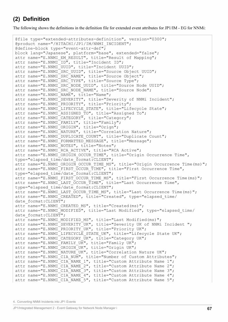
(2) DefinitionThe following shows the definitions in the definition file for extended event attributes for JP1/IM - EG for NNMi:
@file type="extended-attributes-definition", version="0300";@product name="/HITACHI/JP1/IM/NNMI_INCIDENT";@define-block type="event-attr-def";block lang="Japanese", platform="base", extended="false";attr name="E.NNMI_EM_RESULT", title="Result of Mapping";attr name="E.NNMI_ID", title="Incident ID";attr name="E.NNMI_UUID", title="Incident UUID";attr name="E.NNMI_SRC_UUID", title="Source Object UUID";attr name="E.NNMI_SRC_NAME", title="Source Object";attr name="E.NNMI_SRC_TYPE", title="Source Type";attr name="E.NNMI_SRC_NODE_UUID", title="Source Node UUID";attr name="E.NNMI_SRC_NODE_NAME", title="Source Node";attr name="E.NNMI_NAME", title="Name";attr name="E.NNMI_SEVERITY", title="Severity of NNMi Incident";attr name="E.NNMI_PRIORITY", title="Priority";attr name="E.NNMI_LIFECYCLE_STATE", title="Lifecycle State";attr name="E.NNMI_ASSIGNED_TO", title="Assigned To";attr name="E.NNMI_CATEGORY", title="Category";attr name="E.NNMI_FAMILY", title="Family";attr name="E.NNMI_ORIGIN", title="Orign";attr name="E.NNMI_NATURE", title="Correlation Nature";attr name="E.NNMI_DUPLICATE_COUNT", title="Duplicate Count";attr name="E.NNMI_FORMATTED_MESSAGE", title="Message";attr name="E.NNMI_NOTES", title="Notes";attr name="E.NNMI_RCA_ACTIVE", title="RCA Active";attr name="E.NNMI_ORIGIN_OCCUR_TIME", title="Origin Occurrence Time", type="elapsed_time/date_format:CLIENT";attr name="E.NNMI_ORIGIN_OCCUR_TIME_MS", title="Origin Occurrence Time(ms)";attr name="E.NNMI_FIRST_OCCUR_TIME", title="First Occurrence Time", type="elapsed_time/date_format:CLIENT";attr name="E.NNMI_FIRST_OCCUR_TIME_MS", title="First Occurrence Time(ms)";attr name="E.NNMI_LAST_OCCUR_TIME", title="Last Occurrence Time", type="elapsed_time/date_format:CLIENT";attr name="E.NNMI_LAST_OCCUR_TIME_MS", title="Last Occurrence Time(ms)";attr name="E.NNMI_CREATED", title="Created", type="elapsed_time/date_format:CLIENT";attr name="E.NNMI_CREATED_MS", title="Created(ms)";attr name="E.NNMI_MODIFIED", title="Last Modified", type="elapsed_time/date_format:CLIENT";attr name="E.NNMI_MODIFIED_MS", title="Last Modified(ms)";attr name="E.NNMI_SEVERITY_UK", title="Severity UK of NNMi Incident ";attr name="E.NNMI_PRIORITY_UK", title="Priority UK";attr name="E.NNMI_LIFECYCLE_STATE_UK", title="Lifecycle State UK";attr name="E.NNMI_CATEGORY_UK", title="Category UK";attr name="E.NNMI_FAMILY_UK", title="Family UK";attr name="E.NNMI_ORIGIN_UK", title="Origin UK";attr name="E.NNMI_NATURE_UK", title="Correlation Nature UK";attr name="E.NNMI_CIA_NUM", title="Number of Custom Attributes";attr name="E.NNMI_CIA_NAME_1", title="Custom Attribute Name 1";attr name="E.NNMI_CIA_NAME_2", title="Custom Attribute Name 2";attr name="E.NNMI_CIA_NAME_3", title="Custom Attribute Name 3";attr name="E.NNMI_CIA_NAME_4", title="Custom Attribute Name 4";attr name="E.NNMI_CIA_NAME_5", title="Custom Attribute Name 5";
4. Converting NNMi Incidents into JP1 Events
JP1/Integrated Management 2 - Event Gateway for Network Node Manager i 67
attr name="E.NNMI_CIA_NAME_6", title="Custom Attribute Name 6";attr name="E.NNMI_CIA_NAME_7", title="Custom Attribute Name 7";attr name="E.NNMI_CIA_NAME_8", title="Custom Attribute Name 8";attr name="E.NNMI_CIA_NAME_9", title="Custom Attribute Name 9";attr name="E.NNMI_CIA_NAME_10", title="Custom Attribute Name 10";attr name="E.NNMI_CIA_NAME_11", title="Custom Attribute Name 11";attr name="E.NNMI_CIA_NAME_12", title="Custom Attribute Name 12";attr name="E.NNMI_CIA_NAME_13", title="Custom Attribute Name 13";attr name="E.NNMI_CIA_NAME_14", title="Custom Attribute Name 14";attr name="E.NNMI_CIA_NAME_15", title="Custom Attribute Name 15";attr name="E.NNMI_CIA_NAME_16", title="Custom Attribute Name 16";attr name="E.NNMI_CIA_NAME_17", title="Custom Attribute Name 17";attr name="E.NNMI_CIA_NAME_18", title="Custom Attribute Name 18";attr name="E.NNMI_CIA_NAME_19", title="Custom Attribute Name 19";attr name="E.NNMI_CIA_NAME_20", title="Custom Attribute Name 20";attr name="E.NNMI_CIA_TYPE_1", title="Custom Attribute Type 1";attr name="E.NNMI_CIA_TYPE_2", title="Custom Attribute Type 2";attr name="E.NNMI_CIA_TYPE_3", title="Custom Attribute Type 3";attr name="E.NNMI_CIA_TYPE_4", title="Custom Attribute Type 4";attr name="E.NNMI_CIA_TYPE_5", title="Custom Attribute Type 5";attr name="E.NNMI_CIA_TYPE_6", title="Custom Attribute Type 6";attr name="E.NNMI_CIA_TYPE_7", title="Custom Attribute Type 7";attr name="E.NNMI_CIA_TYPE_8", title="Custom Attribute Type 8";attr name="E.NNMI_CIA_TYPE_9", title="Custom Attribute Type 9";attr name="E.NNMI_CIA_TYPE_10", title="Custom Attribute Type 10";attr name="E.NNMI_CIA_TYPE_11", title="Custom Attribute Type 11";attr name="E.NNMI_CIA_TYPE_12", title="Custom Attribute Type 12";attr name="E.NNMI_CIA_TYPE_13", title="Custom Attribute Type 13";attr name="E.NNMI_CIA_TYPE_14", title="Custom Attribute Type 14";attr name="E.NNMI_CIA_TYPE_15", title="Custom Attribute Type 15";attr name="E.NNMI_CIA_TYPE_16", title="Custom Attribute Type 16";attr name="E.NNMI_CIA_TYPE_17", title="Custom Attribute Type 17";attr name="E.NNMI_CIA_TYPE_18", title="Custom Attribute Type 18";attr name="E.NNMI_CIA_TYPE_19", title="Custom Attribute Type 19";attr name="E.NNMI_CIA_TYPE_20", title="Custom Attribute Type 20";attr name="E.NNMI_CIA_VALUE_1", title="Custom Attribute Value 1";attr name="E.NNMI_CIA_VALUE_2", title="Custom Attribute Value 2";attr name="E.NNMI_CIA_VALUE_3", title="Custom Attribute Value 3";attr name="E.NNMI_CIA_VALUE_4", title="Custom Attribute Value 4";attr name="E.NNMI_CIA_VALUE_5", title="Custom Attribute Value 5";attr name="E.NNMI_CIA_VALUE_6", title="Custom Attribute Value 6";attr name="E.NNMI_CIA_VALUE_7", title="Custom Attribute Value 7";attr name="E.NNMI_CIA_VALUE_8", title="Custom Attribute Value 8";attr name="E.NNMI_CIA_VALUE_9", title="Custom Attribute Value 9";attr name="E.NNMI_CIA_VALUE_10", title="Custom Attribute Value 10";attr name="E.NNMI_CIA_VALUE_11", title="Custom Attribute Value 11";attr name="E.NNMI_CIA_VALUE_12", title="Custom Attribute Value 12";attr name="E.NNMI_CIA_VALUE_13", title="Custom Attribute Value 13";attr name="E.NNMI_CIA_VALUE_14", title="Custom Attribute Value 14";attr name="E.NNMI_CIA_VALUE_15", title="Custom Attribute Value 15";attr name="E.NNMI_CIA_VALUE_16", title="Custom Attribute Value 16";attr name="E.NNMI_CIA_VALUE_17", title="Custom Attribute Value 17";attr name="E.NNMI_CIA_VALUE_18", title="Custom Attribute Value 18";attr name="E.NNMI_CIA_VALUE_19", title="Custom Attribute Value 19";attr name="E.NNMI_CIA_VALUE_20", title="Custom Attribute Value 20";attr name="E.NNMI_PROTOCOL", title="NNMi Protocol";attr name="E.NNMI_SERVER", title="NNMi Server";attr name="E.NNMI_PORT", title="NNMi Port";
4. Converting NNMi Incidents into JP1 Events
JP1/Integrated Management 2 - Event Gateway for Network Node Manager i 68
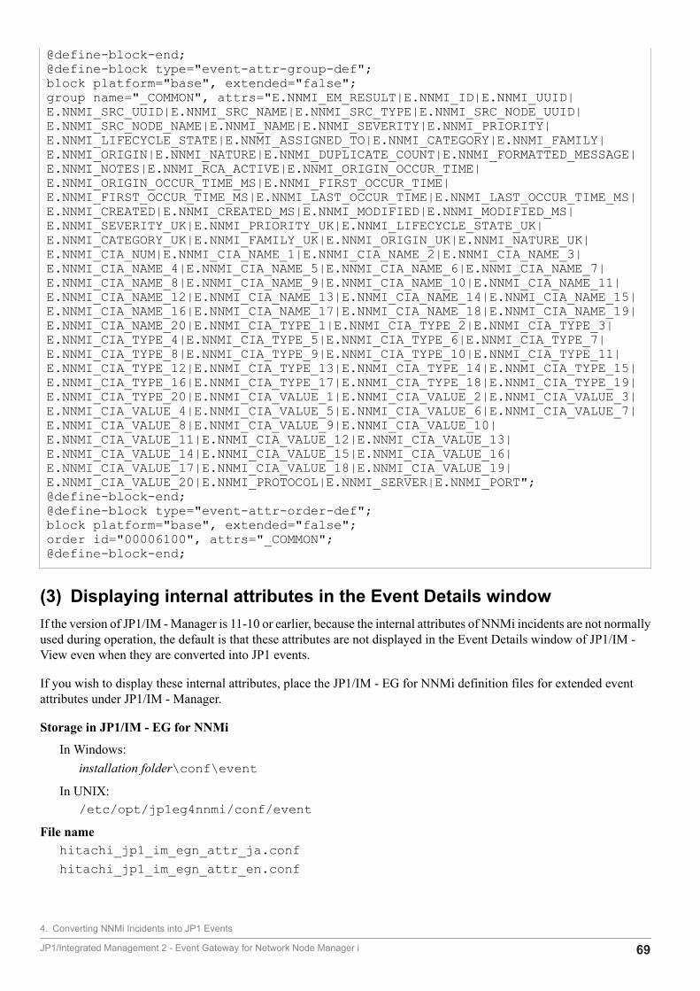
@define-block-end;@define-block type="event-attr-group-def";block platform="base", extended="false";group name="_COMMON", attrs="E.NNMI_EM_RESULT|E.NNMI_ID|E.NNMI_UUID|E.NNMI_SRC_UUID|E.NNMI_SRC_NAME|E.NNMI_SRC_TYPE|E.NNMI_SRC_NODE_UUID|E.NNMI_SRC_NODE_NAME|E.NNMI_NAME|E.NNMI_SEVERITY|E.NNMI_PRIORITY|E.NNMI_LIFECYCLE_STATE|E.NNMI_ASSIGNED_TO|E.NNMI_CATEGORY|E.NNMI_FAMILY|E.NNMI_ORIGIN|E.NNMI_NATURE|E.NNMI_DUPLICATE_COUNT|E.NNMI_FORMATTED_MESSAGE|E.NNMI_NOTES|E.NNMI_RCA_ACTIVE|E.NNMI_ORIGIN_OCCUR_TIME|E.NNMI_ORIGIN_OCCUR_TIME_MS|E.NNMI_FIRST_OCCUR_TIME|E.NNMI_FIRST_OCCUR_TIME_MS|E.NNMI_LAST_OCCUR_TIME|E.NNMI_LAST_OCCUR_TIME_MS|E.NNMI_CREATED|E.NNMI_CREATED_MS|E.NNMI_MODIFIED|E.NNMI_MODIFIED_MS|E.NNMI_SEVERITY_UK|E.NNMI_PRIORITY_UK|E.NNMI_LIFECYCLE_STATE_UK|E.NNMI_CATEGORY_UK|E.NNMI_FAMILY_UK|E.NNMI_ORIGIN_UK|E.NNMI_NATURE_UK|E.NNMI_CIA_NUM|E.NNMI_CIA_NAME_1|E.NNMI_CIA_NAME_2|E.NNMI_CIA_NAME_3|E.NNMI_CIA_NAME_4|E.NNMI_CIA_NAME_5|E.NNMI_CIA_NAME_6|E.NNMI_CIA_NAME_7|E.NNMI_CIA_NAME_8|E.NNMI_CIA_NAME_9|E.NNMI_CIA_NAME_10|E.NNMI_CIA_NAME_11|E.NNMI_CIA_NAME_12|E.NNMI_CIA_NAME_13|E.NNMI_CIA_NAME_14|E.NNMI_CIA_NAME_15|E.NNMI_CIA_NAME_16|E.NNMI_CIA_NAME_17|E.NNMI_CIA_NAME_18|E.NNMI_CIA_NAME_19|E.NNMI_CIA_NAME_20|E.NNMI_CIA_TYPE_1|E.NNMI_CIA_TYPE_2|E.NNMI_CIA_TYPE_3|E.NNMI_CIA_TYPE_4|E.NNMI_CIA_TYPE_5|E.NNMI_CIA_TYPE_6|E.NNMI_CIA_TYPE_7|E.NNMI_CIA_TYPE_8|E.NNMI_CIA_TYPE_9|E.NNMI_CIA_TYPE_10|E.NNMI_CIA_TYPE_11|E.NNMI_CIA_TYPE_12|E.NNMI_CIA_TYPE_13|E.NNMI_CIA_TYPE_14|E.NNMI_CIA_TYPE_15|E.NNMI_CIA_TYPE_16|E.NNMI_CIA_TYPE_17|E.NNMI_CIA_TYPE_18|E.NNMI_CIA_TYPE_19|E.NNMI_CIA_TYPE_20|E.NNMI_CIA_VALUE_1|E.NNMI_CIA_VALUE_2|E.NNMI_CIA_VALUE_3|E.NNMI_CIA_VALUE_4|E.NNMI_CIA_VALUE_5|E.NNMI_CIA_VALUE_6|E.NNMI_CIA_VALUE_7|E.NNMI_CIA_VALUE_8|E.NNMI_CIA_VALUE_9|E.NNMI_CIA_VALUE_10|E.NNMI_CIA_VALUE_11|E.NNMI_CIA_VALUE_12|E.NNMI_CIA_VALUE_13|E.NNMI_CIA_VALUE_14|E.NNMI_CIA_VALUE_15|E.NNMI_CIA_VALUE_16|E.NNMI_CIA_VALUE_17|E.NNMI_CIA_VALUE_18|E.NNMI_CIA_VALUE_19|E.NNMI_CIA_VALUE_20|E.NNMI_PROTOCOL|E.NNMI_SERVER|E.NNMI_PORT";@define-block-end;@define-block type="event-attr-order-def";block platform="base", extended="false";order id="00006100", attrs="_COMMON";@define-block-end;
(3) Displaying internal attributes in the Event Details windowIf the version of JP1/IM - Manager is 11-10 or earlier, because the internal attributes of NNMi incidents are not normallyused during operation, the default is that these attributes are not displayed in the Event Details window of JP1/IM -View even when they are converted into JP1 events.
If you wish to display these internal attributes, place the JP1/IM - EG for NNMi definition files for extended eventattributes under JP1/IM - Manager.
Storage in JP1/IM - EG for NNMi
In Windows:installation folder\conf\event
In UNIX:/etc/opt/jp1eg4nnmi/conf/event
File namehitachi_jp1_im_egn_attr_ja.confhitachi_jp1_im_egn_attr_en.conf
4. Converting NNMi Incidents into JP1 Events
JP1/Integrated Management 2 - Event Gateway for Network Node Manager i 69
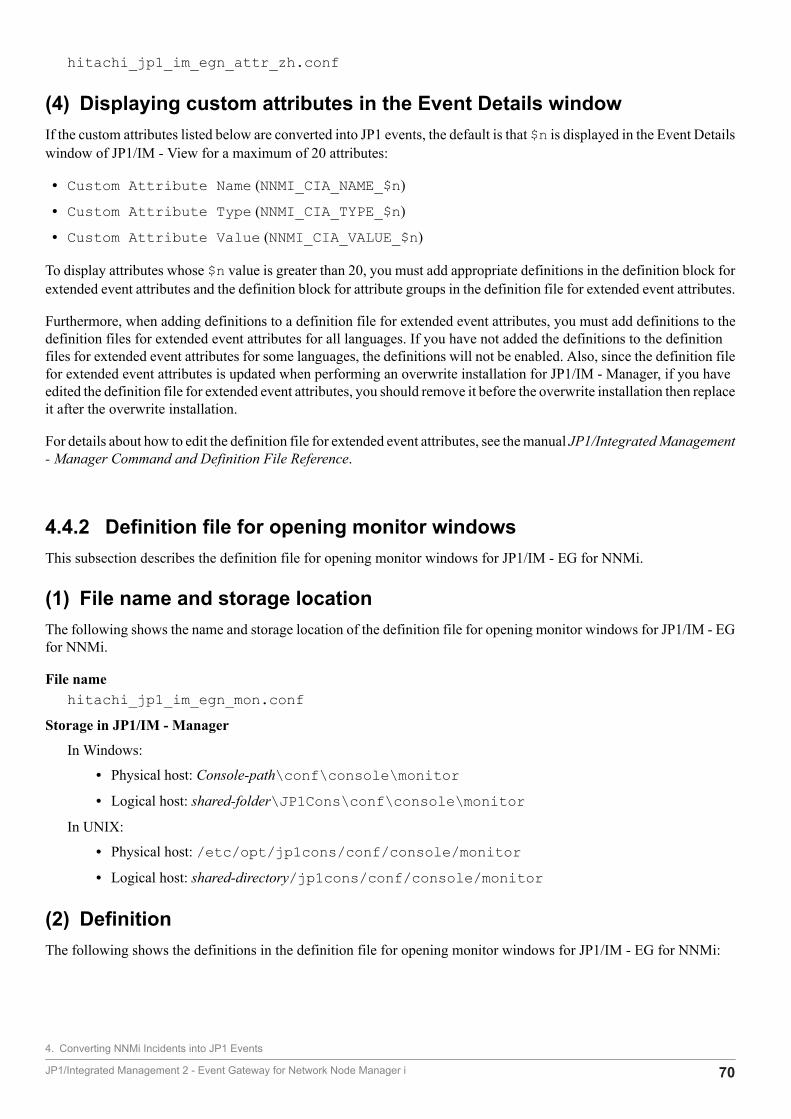
hitachi_jp1_im_egn_attr_zh.conf
(4) Displaying custom attributes in the Event Details windowIf the custom attributes listed below are converted into JP1 events, the default is that $n is displayed in the Event Detailswindow of JP1/IM - View for a maximum of 20 attributes:
• Custom Attribute Name (NNMI_CIA_NAME_$n)
• Custom Attribute Type (NNMI_CIA_TYPE_$n)
• Custom Attribute Value (NNMI_CIA_VALUE_$n)
To display attributes whose $n value is greater than 20, you must add appropriate definitions in the definition block forextended event attributes and the definition block for attribute groups in the definition file for extended event attributes.
Furthermore, when adding definitions to a definition file for extended event attributes, you must add definitions to thedefinition files for extended event attributes for all languages. If you have not added the definitions to the definitionfiles for extended event attributes for some languages, the definitions will not be enabled. Also, since the definition filefor extended event attributes is updated when performing an overwrite installation for JP1/IM - Manager, if you haveedited the definition file for extended event attributes, you should remove it before the overwrite installation then replaceit after the overwrite installation.
For details about how to edit the definition file for extended event attributes, see the manual JP1/Integrated Management- Manager Command and Definition File Reference.
4.4.2 Definition file for opening monitor windowsThis subsection describes the definition file for opening monitor windows for JP1/IM - EG for NNMi.
(1) File name and storage locationThe following shows the name and storage location of the definition file for opening monitor windows for JP1/IM - EGfor NNMi.
File namehitachi_jp1_im_egn_mon.conf
Storage in JP1/IM - Manager
In Windows:
• Physical host: Console-path\conf\console\monitor• Logical host: shared-folder\JP1Cons\conf\console\monitor
In UNIX:
• Physical host: /etc/opt/jp1cons/conf/console/monitor• Logical host: shared-directory/jp1cons/conf/console/monitor
(2) DefinitionThe following shows the definitions in the definition file for opening monitor windows for JP1/IM - EG for NNMi:
4. Converting NNMi Incidents into JP1 Events
JP1/Integrated Management 2 - Event Gateway for Network Node Manager i 70
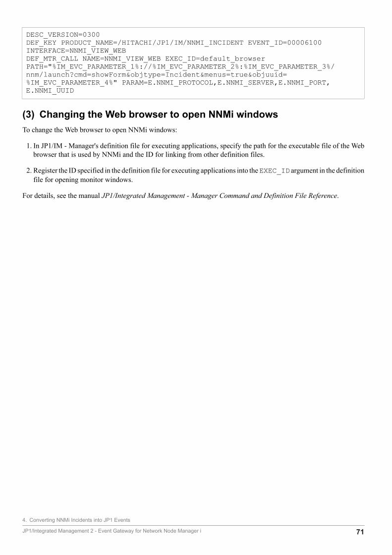
DESC_VERSION=0300DEF_KEY PRODUCT_NAME=/HITACHI/JP1/IM/NNMI_INCIDENT EVENT_ID=00006100 INTERFACE=NNMI_VIEW_WEBDEF_MTR_CALL NAME=NNMI_VIEW_WEB EXEC_ID=default_browser PATH="%IM_EVC_PARAMETER_1%://%IM_EVC_PARAMETER_2%:%IM_EVC_PARAMETER_3%/nnm/launch?cmd=showForm&objtype=Incident&menus=true&objuuid=%IM_EVC_PARAMETER_4%" PARAM=E.NNMI_PROTOCOL,E.NNMI_SERVER,E.NNMI_PORT,E.NNMI_UUID
(3) Changing the Web browser to open NNMi windowsTo change the Web browser to open NNMi windows:
1. In JP1/IM - Manager's definition file for executing applications, specify the path for the executable file of the Webbrowser that is used by NNMi and the ID for linking from other definition files.
2. Register the ID specified in the definition file for executing applications into the EXEC_ID argument in the definitionfile for opening monitor windows.
For details, see the manual JP1/Integrated Management - Manager Command and Definition File Reference.
4. Converting NNMi Incidents into JP1 Events
JP1/Integrated Management 2 - Event Gateway for Network Node Manager i 71

5 Startup and Termination
This chapter describes how to start and terminate JP1/IM - EG for NNMi.
JP1/Integrated Management 2 - Event Gateway for Network Node Manager i 72
5.1 Starting JP1/IM - EG for NNMi
This section describes how to start JP1/IM - EG for NNMi. You must start the services of NNMi and JP1/Base beforeyou can start the JP1/IM - EG for NNMi services.
Automatic startup in a cluster systemFor details about starting JP1/IM - EG for NNMi automatically in a cluster system, see 3.3 Registering into thecluster software.
The startup method depends on the OS.
5.1.1 In WindowsIn Windows, the procedure depends on whether JP1/Base's startup control is used.
When startup control is used to start JP1/IM - EG for NNMiSpecify the definition of JP1/IM - EG for NNMi in the start sequence definition file of JP1/Base. For details, see2.4.3(1) In Windows.
When startup control is not used to start JP1/IM - EG for NNMiFrom Control Panel, choose Administrative Tools and then Services, and then start the services of JP1/IM - EGfor NNMi.
5.1.2 In UNIXIn UNIX, the procedure depends on whether an automated startup script is used.
When an automated startup script is used to start JP1/IM - EG for NNMiSpecify settings so that an automated startup script is called during system startup. For details, see 2.4.3(2) In UNIX.
When an automated startup script is not used to start JP1/IM - EG for NNMiExecute the /etc/opt/jp1eg4nnmi/jegn_start.model script or a file that contains a copy of this script.
ImportantIf automatic startup and automatic termination are set in Linux 7, Oracle Linux 7, CentOS 7, or SUSELinux 12, execute the following command to start JP1/IM - EG for NNMi:
systemctl start jp1_eg4nnmi
5. Startup and Termination
JP1/Integrated Management 2 - Event Gateway for Network Node Manager i 73
5.2 Terminating JP1/IM - EG for NNMi
This section describes how to terminate JP1/IM - EG for NNMi. You must terminate the JP1/IM - EG for NNMi servicesbefore you terminate the services of NNMi and JP1/Base.
Automatic termination in a cluster systemFor details about terminating JP1/IM - EG for NNMi automatically in a cluster system, see 3.3 Registering into thecluster software.
The termination method depends on the OS.
5.2.1 In WindowsIn Windows, the procedure depends on whether JP1/Base's startup control is used.
When startup control is used to start JP1/IM - EG for NNMiIf JP1/Power Monitor has been installed, you can use JP1/Base's startup control to stop the service. If you use startupcontrol, specify the definition of JP1/IM - EG for NNMi in the start sequence definition file of JP1/Base. For details,see 2.4.3(1) In Windows.
When startup control is not used to terminate JP1/IM - EG for NNMiFrom Control Panel, choose Administrative Tools and then Services, and then stop the services of JP1/IM - EGfor NNMi.
5.2.2 In UNIXIn UNIX, the procedure depends on whether an automated stop script is used.
When an automated stop script is used to terminate JP1/IM - EG for NNMiSpecify settings so that an automated stop script is called during system termination. For details, see 2.4.3(2) In UNIX.
When an automated stop script is not used to terminate JP1/IM - EG for NNMiExecute the /etc/opt/jp1eg4nnmi/jegn_stop.model script or a file that contains a copy of this script.
ImportantIf automatic startup and automatic termination are set in Linux 7, Oracle Linux 7, CentOS 7, or SUSELinux 12, execute the following command to terminate JP1/IM - EG for NNMi:
systemctl stop jp1_eg4nnmi
5. Startup and Termination
JP1/Integrated Management 2 - Event Gateway for Network Node Manager i 74

6 JP1/IM - EG for NNMi Operations
This chapter describes backup and restoration of JP1/IM - EG for NNMi and how to change settings.
JP1/Integrated Management 2 - Event Gateway for Network Node Manager i 75
6.1 Backup and restoration
This section describes backup and restoration of JP1/IM - EG for NNMi.
If a problem occurs in JP1/IM - EG for NNMi and you have made a backup of the settings, you can configure the systemin the same environment and restart operation. Immediately after you set up JP1/IM - EG for NNMi and whenever youmake changes to the system, it is important that you make a backup of the settings.
For details about backing up and restoring NNMi, see the documentation for the NNMi product.
6.1.1 Backing up the settingsThis subsection describes backup of the JP1/IM - EG for NNMi settings.
Whenever you make a backup of JP1/IM - EG for NNMi, you should also make a backup of JP1/Base. For details aboutbacking up the definition files set by the JP1/Base user, see the JP1/Base User's Guide.
You can use any appropriate method to make a backup, such as by copying the files. You can make a backup while JP1/IM - EG for NNMi is running.
The following table lists the JP1/IM - EG for NNMi files to be backed up.
Table 6‒1: JP1/IM - EG for NNMi files to be backed up
File name Description
imevtgw_nnmi.conf Operation definition file
imevtgw_nnmi_cia_map.conf Custom attribute mapping definition file#
imevtgw_nnmi_forward_filter.conf NNMi incident forwarding filter definition file
imevgw_nnmi_label_mapping_category_en.conf Mapping definition file (for category)
imevgw_nnmi_label_mapping_family_en.conf Mapping definition file (for family)
#If custom attribute mapping is not set, this file does not exist.
The files to be backed up are stored at the following locations:
In Windows:
• Physical host: EG-for-NNMi-path\conf• Logical host: shared-folder\JP1EG4NNMI\conf
In UNIX:
• Physical host: /etc/opt/jp1eg4nnmi/conf• Logical host: shared-directory/jp1eg4nnmi/conf
6.1.2 Restoring the settingsThis subsection describes restoration of the JP1/IM - EG for NNMi settings.
6. JP1/IM - EG for NNMi Operations
JP1/Integrated Management 2 - Event Gateway for Network Node Manager i 76

Before you restore from a backup of JP1/IM - EG for NNMi, you must first restore JP1/Base. Prior to restoring backupfiles to their original locations, make sure that all the following conditions are satisfied:
Conditions
• JP1/IM - EG for NNMi and JP1/Base have both been terminated.
• JP1/IM - EG for NNMi and JP1/Base were both installed and the cluster setup command has already beenexecuted (applicable in the case of cluster operation).
• JP1/Base was set up in a logical host environment (applicable in the case of cluster operation).
• The shared disk is online (applicable in the case of cluster operation).
6. JP1/IM - EG for NNMi Operations
JP1/Integrated Management 2 - Event Gateway for Network Node Manager i 77
6.2 Changing settings
This section describes how to edit the definition files for JP1/IM - EG for NNMi and the procedures required in orderto change the system environment for the computer on which JP1/IM - EG for NNMi is running.
If you have changed the NNMi system environment, you must execute overwrite setup; for details, see 2.4.1 Executingthe setup command.
6.2.1 Editing the definition filesYou can edit the following definition files for JP1/IM - EG for NNMi (this editing can be performed while the servicesof JP1/IM - EG for NNMi are running):
• Operation definition file#
• NNMi incident forwarding filter definition file
• Mapping definition file (for category)
• Mapping definition file (for family)
• Extended startup process definition file
#You cannot edit the operation definition file directly. Instead, you must use the jegn_setup command to edit it.For details about the jegn_setup command, see jegn_setup in 7. Commands.
If you have edited any of the definition files listed above while the JP1/IM - EG for NNMi services were running, youmust execute the jegn_spmd_reload command to reload the definition files in order to apply the changes. Thechanges in the definition files are not applied immediately after execution of the jegn_spmd_reload command, butthey are applied when the next polling occurs after the reload.
If an error occurs while the jegn_spmd_reload command checks the definition, operations continue using thedefinitions that were in effect before the change. For details about the jegn_spmd_reload command, seejegn_spmd_reload in 7. Commands.
For details about the settings in the definition files, see 4. Converting NNMi Incidents into JP1 Events and F.1 Extendedstartup process definition file (jegn_service_0700.conf).
Reference:If you edit definition files while the JP1/IM - EG for NNMi services are stopped, the new settings take effect thenext time the services are started.
6.2.2 Changing the settings of the host name, IP address, and port numberon which JP1/IM - EG for NNMi is running
This subsection describes the procedures for changing the settings of the host name, IP address, and port number onwhich JP1/IM - EG for NNMi is running.
For details about how to change the JP1/Base settings, see the JP1/Base User's Guide.
6. JP1/IM - EG for NNMi Operations
JP1/Integrated Management 2 - Event Gateway for Network Node Manager i 78
(1) Procedure for changing the host name, IP address, or port numberTo change the host name, IP address, or port number:
1. Terminate JP1/IM - EG for NNMi.
2. Change the host name, IP address, or port number, as necessary.
3. Restart JP1/IM - EG for NNMi.
(2) Procedure for editing the hosts file, jp1hosts definition file, andjp1hosts2 definition file
This subsection describes how to change the host information specified in the hosts file, jp1hosts definition file,or jp1hosts2 definition file while JP1/IM - EG for NNMi is running.
Changing information of a host on which JP1/IM - EG for NNMi is installedAfter you have changed the host information, restart JP1/IM - EG for NNMi.
Adding or changing information of a host on which JP1/IM - EG for NNMi is not installedIf you have added or changed host information, you must either restart JP1/IM - EG for NNMi or execute thejegn_spmd_reload command to reload the new settings. For details about the jegn_spmd_reloadcommand, see jegn_spmd_reload in 7. Commands.
(3) In the case of cluster operationIf you change the logical host name in a cluster system, delete the logical host that was in effect before the change. Thenset up the logical host again that will be in effect after the change so that cluster operation is enabled.
For details about how to delete the logical host, see 3.4 Deleting the logical host. For details about how to set up thelogical host, see 3.2 Installing and setting up the logical host.
If the logical host name to be changed is specified in the NNMi incident forwarding filter definition file and the customattribute mapping definition file, check and revise the settings in these files.
For details about the settings of these files, see 4. Converting NNMi Incidents into JP1 Events.
6.2.3 Changing the date and time of the system on which JP1/IM - EG forNNMi is running
This subsection describes the procedures for changing the system date and time while JP1/IM - EG for NNMi is running.
(1) Procedures for changing the system date and timeThis subsection describes the procedures for changing the system date and time.
Setting the system date and time to an earlier timeAvoid changing the system date and time to an earlier time. If you do so, JP1 events might not be issued or duplicateJP1 events might be issued.To set the system date and time to an earlier time:
1. Terminate JP1/IM - EG for NNMi.
6. JP1/IM - EG for NNMi Operations
JP1/Integrated Management 2 - Event Gateway for Network Node Manager i 79
2. Set the system date and time.
3. Delete the imevtgw_nnmi_last_forwarded.conf file#.
4. Keep JP1/IM - EG for NNMi stopped until the system date and time that was in effect before the change isreached (until the date and time at which step 2 was performed).
5. Execute the following command to check the value of the startup option:jegn_setup -list [-h logical-host-name]
6. Execute the following command:jegn_setup -update [-h logical-host-name] -startup 0
7. Start JP1/IM - EG for NNMi.
8. Execute the following command to restore the value of the startup option:jegn_setup -update [-h logical-host-name] -startup the-value-checked-in-step-5
9. Execute the following command to apply the value of the startup option specified in step 8:jegn_spmd_reload [-h logical-host-name]
Advancing the system date and time to a point in the futureTo advance the system date and time to a point in the future:
1. Terminate JP1/IM - EG for NNMi.
2. Set the system date and time.
3. Delete the imevtgw_nnmi_last_forwarded.conf file#.
4. Execute the following command to check the value of the startup option:jegn_setup -list [-h logical-host-name]
5. Execute the following command:jegn_setup -update [-h logical-host-name] -startup 0
6. Start JP1/IM - EG for NNMi.
7. Execute the following command to restore the value of the startup option:jegn_setup -update [-h logical-host-name] -startup the-value-checked-in-step-4
8. Execute the following command to apply the value of the startup option specified in step 7:jegn_spmd_reload [-h logical-host-name]
#The imevtgw_nnmi_last_forwarded.conf file is stored at the following locations:
In Windows
• Physical host: installation folder\JP1EG4NNMI\dat• Logical-host: shared-folder\JP1EG4NNMI\dat
In UNIX
• Physical host: /var/opt/jp1eg4nnmi/dat• Logical-host:shared-directory/jp1eg4nnmi/dat
(2) Procedure for changing the time zone in the systemThis subsection describes the procedure for changing the time zone in the system. For details about the procedures andnotes for NNMi, see the appropriate documentation for the specific NNMi products.
6. JP1/IM - EG for NNMi Operations
JP1/Integrated Management 2 - Event Gateway for Network Node Manager i 80
1. Terminate JP1/IM - EG for NNMi.
2. Change the time zone in the system.
3. Delete the imevtgw_nnmi_last_forwarded.conf file#.
4. Execute the following command to check the value of the startup option:jegn_setup -list [-h logical-host-name]
5. Execute the following command:jegn_setup -update [-h logical-host-name] -startup 0
6. Start JP1/IM - EG for NNMi.
7. Execute the following command to restore the value of the startup option:jegn_setup -update [-h logical-host-name] -startup the-value-checked-in-step-4
8. Execute the following command to apply the value of the startup option specified in step 7:jegn_spmd_reload [-h logical-host-name]
#The imevtgw_nnmi_last_forwarded.conf file is stored at the following locations:
In Windows
• Physical host: installation folder\JP1EG4NNMI\dat• Logical-host: shared-folder\JP1EG4NNMI\dat
In UNIX
• Physical host: /var/opt/jp1eg4nnmi/dat• Logical-host:shared-directory/jp1eg4nnmi/dat
6. JP1/IM - EG for NNMi Operations
JP1/Integrated Management 2 - Event Gateway for Network Node Manager i 81

6.3 Notes regarding operation
• Please invalidate the dampening function of the NNMi incident by the following commands.nnmsetdampenedinterval.ovpl -hours 0 -minutes 0 -seconds 0When the dampenin function is effective, the incident not displayed in an incident view of NNMi might be displayedin an integrated console of JP1/IM-Manager.
• When this product is used in an IPv4/IPv6 dual-stack environment, the comparison keywords that can be used forsource nodes (correlation conversion) (attribute name: SRC) in the NNMi incident forwarding filter definition filecan be used only for NNMi incidents in the IPv4 stack. These comparison keywords cannot be used for NNMiincidents in the IPv6 stack.
• When the OS is shut down, the following error message might be output tologs such as the event log or integratedtrace log:KAVB3737-E The JP1_EGN jegneg4nnmi terminated abnormally.When the OS is shut down, the Service Control Manager (SCM) sends a stop request to the services of this product.However, the jegneg4nnmi process might be forcibly stopped by the OS. In this case, the KAVB3737-E message isoutput, but there are no operation problems.
• When using antivirus software, exclude the installation directory and all subdirectories of this product from thescope of virus scans.
6. JP1/IM - EG for NNMi Operations
JP1/Integrated Management 2 - Event Gateway for Network Node Manager i 82

Part 3: Reference
7 Commands
This chapter describes the syntax of the commands that can be used in JP1/IM - EG for NNMi.
JP1/Integrated Management 2 - Event Gateway for Network Node Manager i 83
Format of command explanations
This section describes the format of the explanations of the commands.
The explanation of each command consists of the items described below. Note that not all items are applicable to allcommands.
FunctionDescribes the function of the command.
FormatDescribes the command's format.
Execution permissionDescribes the user permissions required in order to execute the command.
Storage directoryDescribes the command's storage location.
ArgumentsDescribes the command's arguments.
Arguments are case sensitive.
NotesProvides additional information about the command.
Return valuesDescribes the command's return values.
For details about the messages that are displayed during command execution, see 9. Messages.
7. Commands
JP1/Integrated Management 2 - Event Gateway for Network Node Manager i 84
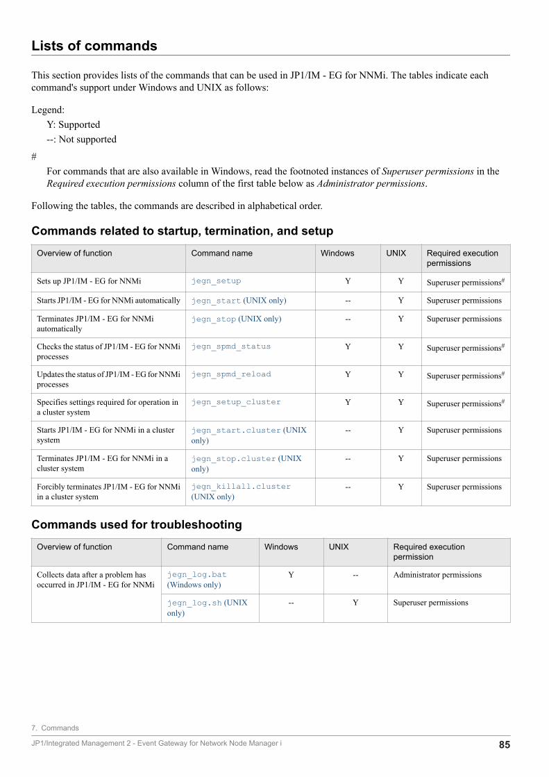
Lists of commands
This section provides lists of the commands that can be used in JP1/IM - EG for NNMi. The tables indicate eachcommand's support under Windows and UNIX as follows:
Legend:Y: Supported--: Not supported
#For commands that are also available in Windows, read the footnoted instances of Superuser permissions in theRequired execution permissions column of the first table below as Administrator permissions.
Following the tables, the commands are described in alphabetical order.
Commands related to startup, termination, and setup
Overview of function Command name Windows UNIX Required executionpermissions
Sets up JP1/IM - EG for NNMi jegn_setup Y Y Superuser permissions#
Starts JP1/IM - EG for NNMi automatically jegn_start (UNIX only) -- Y Superuser permissions
Terminates JP1/IM - EG for NNMiautomatically
jegn_stop (UNIX only) -- Y Superuser permissions
Checks the status of JP1/IM - EG for NNMiprocesses
jegn_spmd_status Y Y Superuser permissions#
Updates the status of JP1/IM - EG for NNMiprocesses
jegn_spmd_reload Y Y Superuser permissions#
Specifies settings required for operation ina cluster system
jegn_setup_cluster Y Y Superuser permissions#
Starts JP1/IM - EG for NNMi in a clustersystem
jegn_start.cluster (UNIXonly)
-- Y Superuser permissions
Terminates JP1/IM - EG for NNMi in acluster system
jegn_stop.cluster (UNIXonly)
-- Y Superuser permissions
Forcibly terminates JP1/IM - EG for NNMiin a cluster system
jegn_killall.cluster(UNIX only)
-- Y Superuser permissions
Commands used for troubleshooting
Overview of function Command name Windows UNIX Required executionpermission
Collects data after a problem hasoccurred in JP1/IM - EG for NNMi
jegn_log.bat(Windows only)
Y -- Administrator permissions
jegn_log.sh (UNIXonly)
-- Y Superuser permissions
7. Commands
JP1/Integrated Management 2 - Event Gateway for Network Node Manager i 85
jegn_killall.cluster (UNIX only)
FunctionThis command executes forcible termination of the JP1/IM - EG for NNMi processes when you are operating in a clustersystem.
If you execute the jegn_stop.cluster command while node switching is underway, the processes might not stopand node switching might fail. Because this command terminates processes forcibly, use it only when processes cannotbe terminated by the normal method of stopping the JP1/IM - EG for NNMi services.
The command is able to terminate the following processes:
• Process management (jegn_spmd)
• Main service (jegneg4nnmi)
Format
jegn_killall.cluster [logical-host-name]
Execution permissionSuperuser permissions
Storage directory/etc/opt/jp1eg4nnmi
Argumentslogical-host-name
Specifies the name of the logical host on which this command is to be executed. The permitted length is from 1 to 32characters (bytes). If this option is omitted, the command assumes the logical host specified in the JP1_HOSTNAMEenvironment variable. If the JP1_HOSTNAME environment variable is not specified, the command assumes the physicalhost.
NotesThis command checks only the first 32 bytes of logical host names and then forcibly terminates processes at any hostwith a matching name. It cannot forcibly terminate processes at a logical host whose name consists of more than 32bytes.
Return values0 Normal termination
1 No logical host name was specified
2 There is no log directory
7. Commands
JP1/Integrated Management 2 - Event Gateway for Network Node Manager i 86
jegn_log.bat (Windows only)
FunctionThis is a tool for collecting data in the event of a problem in JP1/IM - EG for NNMi. The data collected by this toolincludes JP1/IM - EG for NNMi maintenance data, OS system information, and integrated trace logs.
This tool is a batch file. It cannot be customized by the user.
When you execute this tool, the data is classified into primary and secondary data categories and stored directly underthe specified data storage folder.
Primary data is collected for purposes such as identifying an error and investigating the causes of a minor problem. Itconsists of the minimum amount of log information and settings files. Secondary data provides the detailed informationneeded for an in-depth investigation of an error. It consists of data such as the Windows event log, a crash dump, andthe JP1/Base event database.
If necessary, use a program such as a compression tool to compress the collected data.
For details about the data that can be collected by this tool, see 10.3.1 Data to be collected (in Windows).
Format
jegn_log.bat -f data-storage-folder-name [-h logical-host-name] [-t] [-n] [-p] [-r] [-q]
Execution permissionAdministrator permissions. If UAC is enabled, however, execute the command from the administrator console.
Storage directoryEG-for-NNMi-path\tools
Arguments-f data-storage-folder-name
Specifies the name of the folder to which the collected data is to be output, expressed as an absolute path or a pathrelative to the location where the command is executed. If the path contains a space, enclose the entire path in double-quotation marks ("). This option is mandatory.
If a nonexistent folder is specified, a new folder is created with the specified name. If an existing folder is specified, thecontents of that folder are deleted and then the specified folder is created. Do not specify the name of a folder thatcontains files that you do not want to delete.
-h logical-host-name
Specifies the name of the logical host when you are operating in a cluster system. The permitted length is from 1 to 255characters (bytes). When this option is specified, the command collects data for the logical host as well as for the physical
7. Commands
JP1/Integrated Management 2 - Event Gateway for Network Node Manager i 87
host. If this option is omitted, the command collects data for the physical host only. If you are not using a cluster system,there is no need to specify this option.
If this option is omitted when you are not operating in a cluster system, the logical host name specified in theJP1_HOSTNAME environment variable is assumed. However, if you omit this option while you are operating in a clustersystem, the logical host name specified in the JP1_HOSTNAME environment variable will not be assumed. Therefore,when you use a cluster system, you must specify the logical host name in this option.
-t
Specifies that the hosts and services files are not to be collected.
-n
Specifies that the maintenance data for JP1/Base is not to be collected.
-p
Specifies that the JP1/Base event database is not to be collected.
-r
Specifies that the command execution log files for JP1/Base are not to be collected.
-q
Specifies that there is no need to wait for a response confirming that data collection processing is to be resumed.
If the -q option is omitted, the system waits for a response when it displays a message asking whether the processingis to be resumed.
Notes• A huge amount of data can be collected by this tool. Before you execute this tool, you must estimate the amount of
storage space that will be required and check the available space on your machine. For details about the amount ofdata that can be collected, see the Release Notes for JP1/IM - EG for NNMi.
• Do not execute this tool more than once. If it is executed multiple times, the collected data might be overwritten ordata collection might fail.
• If a file to be collected cannot be found, the tool might display a message such as The file was notfound; however, no action is necessary in such a case.
• If you execute the data collection command in Windows, the prompt Refreshing System Information...appears, but do not click the Cancel button. If you click the Cancel button, part of the information cannot be collected.
Return values0 Normal termination
8 Abnormal termination
7. Commands
JP1/Integrated Management 2 - Event Gateway for Network Node Manager i 88

jegn_log.sh (UNIX only)
FunctionThis is a tool for collecting data in the event of a problem in JP1/IM - EG for NNMi. The data collected by this toolincludes JP1/IM - EG for NNMi maintenance data, OS system information, and integrated trace logs.
This tool is a shell script. It cannot be customized by the user.
When you execute this tool, it classifies the target directories or files used for data collection into primary data andsecondary data categories, archives the data directly under the specified data storage directory, and then createscompressed files.
Primary data is collected for purposes such as identifying an error and investigating the causes of a minor problem. Itconsists of the minimum amount of log information and settings files. Secondary data provides the detailed informationneeded for an in-depth investigation of an error. It consists of data such as core analysis information and the JP1/Baseevent database.
If a core dump of JP1/IM - EG for NNMi exists at the time you execute this command, the tool displays the KNAG1044-I message asking whether the core dump is to be deleted. If you enter y or yes, the tool deletes the core dump.
For details about the data that can be collected by this tool, see 10.3.2 Data to be collected (in UNIX).
Format
jegn_log.sh -f data-storage-directory-name [-h logical-host-name] [-t] [-u] [-n] [-p] [-r] [-q] [directory-name-or-file-name...]
Execution permissionSuperuser permissions
Storage directory/opt/jp1eg4nnmi/tools
Arguments-f data-storage-directory-name
Specifies the absolute path (without any spaces) of the directory for storing the collected data. This option is mandatory.
If the specified directory already contains data, the tool displays a message asking whether the existing data is to beoverwritten by the collected data. Note that if you specify the -q option, the existing data will be overwritten withoutrequesting confirmation.
If you have specified the name of a device file such as tape, the tool stores the collected data on the device withoutcompressing it.
7. Commands
JP1/Integrated Management 2 - Event Gateway for Network Node Manager i 89
-h logical-host-name
Specifies the name of the logical host when you are operating in a cluster system. The permitted length is from 1 to 255characters (bytes). When this option is specified, the command collects data for the logical host as well as for the physicalhost. If this option is omitted, the command collects data for the physical host only. If you are not using a cluster system,there is no need to specify this option.
If this option is omitted when you are not operating in a cluster system, the logical host name specified in theJP1_HOSTNAME environment variable is assumed. However, if you omit this option while you are operating in a clustersystem, the logical host name specified in the JP1_HOSTNAME environment variable will not be assumed. Therefore,when you use a cluster system, you must specify the logical host name in this option.
-t
Specifies that the hosts, services, and passwd files are not to be collected.
-u
Specifies that core analysis information is not to be collected.
-n
Specifies that the maintenance data for JP1/Base is not to be collected.
-p
Specifies that the JP1/Base event database is not to be collected.
-r
Specifies that the command execution log files for JP1/Base are not to be collected.
-q
Specifies that there is no need to wait for a response confirming that data collection processing is to be resumed.
If the -q option is omitted, the system waits for a response when it displays a message asking whether the processingis to be resumed.
directory-name-or-file-name
Specifies the name of a file or directory to be collected by this tool. Specify an absolute path name. If you specifymultiple names, separate them with the space character.
Note that this option must be the last option specified in the command; it can be specified only after you have specifiedall other options that you need to specify. The collected data is stored as primary data for the physical host.
Notes• A huge amount of data can be collected by this tool. Before you execute this tool, you must estimate the amount of
storage space that will be required and check the available space on your machine. For details about the size of thedata that can be collected, see the Release Notes for JP1/IM - EG for NNMi.
• Do not execute this tool more than once. If it is executed multiple times, the collected data might be overwritten ordata collection might fail.
7. Commands
JP1/Integrated Management 2 - Event Gateway for Network Node Manager i 90

• If a file to be collected cannot be found, the tool might display a message such as The file was notfound; however, no action is necessary in such a case.
Return values0 Normal termination
8 Abnormal termination
7. Commands
JP1/Integrated Management 2 - Event Gateway for Network Node Manager i 91
jegn_setup
FunctionThis command sets up an operating environment for JP1/IM - EG for NNMi.
Format
To perform a new setup
jegn_setup [-h logical-host-name] -user NNMi-user-name -passwd NNMi-password [-port NNMi-port-number] [-lang NNMi-language] [-interval NNMi-incident-reacquisition-interval] [-startup NNMi-incident-acquisition-method] [-ssl availability-of-TLS]
To perform an overwrite setup
jegn_setup -update [-h logical-host-name] [-user NNMi-user-name] [-passwd NNMi-password] [-port NNMi-port-number] [-lang NNMi-language] [-interval NNMi-incident-reacquisition-interval] [-startup NNMi-incident-acquisition-method] [-ssl availability-of-TLS]
To check the operating environment
jegn_setup -list [-h logical-host-name]
Execution permissionIn Windows: Administrator permissions. If UAC is enabled, however, execute the command from the administratorconsole.
In UNIX: Superuser permissions
Storage directory
In Windows:EG-for-NNMi-path\bin
In UNIX:/opt/jp1eg4nnmi/bin
Arguments-h logical-host-name
7. Commands
JP1/Integrated Management 2 - Event Gateway for Network Node Manager i 92
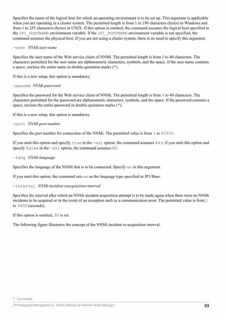
Specifies the name of the logical host for which an operating environment is to be set up. This argument is applicablewhen you are operating in a cluster system. The permitted length is from 1 to 196 characters (bytes) in Windows andfrom 1 to 255 characters (bytes) in UNIX. If this option is omitted, the command assumes the logical host specified inthe JP1_HOSTNAME environment variable. If the JP1_HOSTNAME environment variable is not specified, thecommand assumes the physical host. If you are not using a cluster system, there is no need to specify this argument.
-user NNMi-user-name
Specifies the user name of the Web service client of NNMi. The permitted length is from 1 to 40 characters. Thecharacters permitted for the user name are alphanumeric characters, symbols, and the space. If the user name containsa space, enclose the entire name in double-quotation marks (").
If this is a new setup, this option is mandatory.
-passwd NNMi-password
Specifies the password for the Web service client of NNMi. The permitted length is from 1 to 40 characters. Thecharacters permitted for the password are alphanumeric characters, symbols, and the space. If the password contains aspace, enclose the entire password in double-quotation marks (").
If this is a new setup, this option is mandatory.
-port NNMi-port-number
Specifies the port number for connection of the NNMi. The permitted value is from 1 to 65535.
If you omit this option and specify true in the -ssl option, the command assumes 443; if you omit this option andspecify false in the -ssl option, the command assumes 80.
-lang NNMi-language
Specifies the language of the NNMi that is to be connected. Specify en in this argument.
If you omit this option, the command sets en as the language type specified in JP1/Base.
-interval NNMi-incident-reacquisition-interval
Specifies the interval after which an NNMi incident acquisition attempt is to be made again when there were no NNMiincidents to be acquired or in the event of an exception such as a communication error. The permitted value is from 1to 3600 (seconds).
If this option is omitted, 30 is set.
The following figure illustrates the concept of the NNMi incident re-acquisition interval.
7. Commands
JP1/Integrated Management 2 - Event Gateway for Network Node Manager i 93
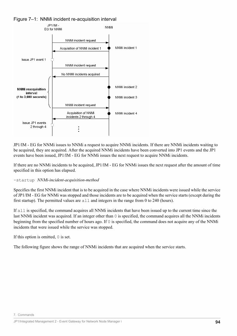
Figure 7‒1: NNMi incident re-acquisition interval
JP1/IM - EG for NNMi issues to NNMi a request to acquire NNMi incidents. If there are NNMi incidents waiting tobe acquired, they are acquired. After the acquired NNMi incidents have been converted into JP1 events and the JP1events have been issued, JP1/IM - EG for NNMi issues the next request to acquire NNMi incidents.
If there are no NNMi incidents to be acquired, JP1/IM - EG for NNMi issues the next request after the amount of timespecified in this option has elapsed.
-startup NNMi-incident-acquisition-method
Specifies the first NNMi incident that is to be acquired in the case where NNMi incidents were issued while the serviceof JP1/IM - EG for NNMi was stopped and those incidents are to be acquired when the service starts (except during thefirst startup). The permitted values are all and integers in the range from 0 to 240 (hours).
If all is specified, the command acquires all NNMi incidents that have been issued up to the current time since thelast NNMi incident was acquired. If an integer other than 0 is specified, the command acquires all the NNMi incidentsbeginning from the specified number of hours ago. If 0 is specified, the command does not acquire any of the NNMiincidents that were issued while the service was stopped.
If this option is omitted, 0 is set.
The following figure shows the range of NNMi incidents that are acquired when the service starts.
7. Commands
JP1/Integrated Management 2 - Event Gateway for Network Node Manager i 94
Figure 7‒2: Range of NNMi incidents that are acquired when the service starts
-ssl availability-of-TLS
Specifies whether TLS is to be used when connection is established with NNMi. To use TLS, specify true. To not useTLS, specify false.
If this option is omitted, false is set.
-update
Specifies that this is an overwrite setup, and only the information in the specified options is to be changed. For theomitted options, the existing information is to be inherited.
If you have executed the jegn_setup command while the services of JP1/IM - EG for NNMi were running, eitherexecute the jegn_spmd_reload command or restart the JP1/IM - EG for NNMi services in order to apply the newinformation. If you execute the jegn_setup command while the JP1/IM - EG for NNMi services are stopped, thespecified information will take effect the next time the services start.
-list
Specifies that the current settings are to be displayed. When you specify this option, each option setting is displayed inthe format option-name:setting. However, the password is always displayed as ********. The following shows anexample of the display:
user:hitachipasswd:********port:80lang:jainterval:30
7. Commands
JP1/Integrated Management 2 - Event Gateway for Network Node Manager i 95

startup:0ssl:false
Return values0 Normal termination
1 Abnormal termination
7. Commands
JP1/Integrated Management 2 - Event Gateway for Network Node Manager i 96
jegn_setup_cluster
FunctionThis command sets up an operating environment for JP1/IM - EG for NNMi when it is used in a cluster system.
Format
To set up an operating environment for the active server:
jegn_setup_cluster -h logical-host-name -d shared-directory-name
To set up an operating environment for the standby server (Windows only):
jegn_setup_cluster -h logical-host-name
Execution permissionIn Windows: Administrator permissions. If UAC is enabled, however, execute the command from the administratorconsole.
In UNIX: Superuser permissions
Storage directory
In Windows:EG-for-NNMi-path\bin
In UNIX:/opt/jp1eg4nnmi/bin
Arguments-h logical-host-name
Specifies the name of the logical host for which the operating environment is to be set up. The permitted length is from1 to 196 characters (bytes) in Windows and from 1 to 255 characters (bytes) in UNIX.
-d shared-directory-name
Specifies the name of the shared directory that is to be used during operation in the cluster system. Specify this optionwhen you are setting up the operating environment for the active server; when this option is omitted, this command setsup the operating environment for the standby server.
NotesWhen you specify the -d option (to set up an operating environment for the active server), the shared disk must bemounted before command execution.
Return values0 Normal termination
1 Abnormal termination
7. Commands
JP1/Integrated Management 2 - Event Gateway for Network Node Manager i 97
jegn_spmd_reload
FunctionThis command updates the status of the JP1/IM - EG for NNMi processes. Whenever you change definition informationfor JP1/IM - EG for NNMi, you must reload the new information in order to apply it.
For details about the definition files that are enabled by execution of the jegn_spmd_reload command, see 6.2.1Editing the definition files.
Format
jegn_spmd_reload [-h logical-host-name] [-t monitoring-period]
Execution permissionIn Windows: Administrator permissions. If UAC is enabled, however, execute the command from the administratorconsole.
In UNIX: Superuser permissions
Storage directory
In Windows:EG-for-NNMi-path\bin
In UNIX:/opt/jp1eg4nnmi/bin
Arguments-h logical-host-name
Specifies the name of the logical host when you are operating in a cluster system. The permitted length is from 1 to 255characters (bytes). If this option is omitted, the command assumes the logical host specified in the JP1_HOSTNAMEenvironment variable. If the JP1_HOSTNAME environment variable is not specified, the command assumes the physicalhost. If you are not using a cluster system, there is no need to specify this argument.
-t monitoring-period
Specifies in seconds the amount of time to wait for termination of the jegn_spmd_reload command. The permittedvalue range is from 0 to 32,767 (seconds). If this option is omitted, 60 is assumed. If the jegn_spmd_reloadcommand does not terminate within the specified amount of time, the system assumes that the jegn_spmd_reloadcommand has failed, in which case operations continue using the definitions that were in effect before the change.
Notes• The jegn_spmd_reload and the jegn_spmd_status commands cannot be executed more than once
concurrently on the same host.
• If a definition file# of this product contains an error, a timeout error occurs when the jegn_spmd_reloadcommand is executed. In such a case, check the integrated trace log for a log related to the error in the definition
7. Commands
JP1/Integrated Management 2 - Event Gateway for Network Node Manager i 98

file. If a definition file contains an error, correct the definition file and then execute the jegn_spmd_reloadcommand.
#For details about definition files, see 6.2.1 Editing the definition files in the manual for this product.
Return values0 Normal termination
Other than 0 Abnormal termination
7. Commands
JP1/Integrated Management 2 - Event Gateway for Network Node Manager i 99
jegn_spmd_status
FunctionThis command checks whether processes managed by JP1/IM - EG for NNMi are running or have terminated. If theprocesses are running normally when the jegn_spmd_status command executes, the command displays the mainservice process name (jegneg4nnmi) and the process ID.
For details about the processes managed by JP1/IM - EG for NNMi, see B. Lists of Processes.
Format
jegn_spmd_status [-h logical-host-name] [-t monitoring-period]
Execution permissionIn Windows: Administrator permissions. If UAC is enabled, however, execute the command from the administratorconsole.
In UNIX: Superuser permissions
Storage directory
In Windows:EG-for-NNMi-path\bin
In UNIX:/opt/jp1eg4nnmi/bin
-h logical-host-name
Specifies the name of the logical host when you are operating in a cluster system. The permitted length is from 1 to 255characters (bytes). If this option is omitted, the command assumes the logical host specified in the JP1_HOSTNAMEenvironment variable. If the JP1_HOSTNAME environment variable is not specified, the command assumes the physicalhost. If you are not using a cluster system, there is no need to specify this argument.
-t monitoring-period
Specifies in seconds the amount of time to wait for termination of the jegn_spmd_status command. The permittedvalue range is from 0 to 32,767 (seconds). If this option is omitted, 60 is assumed. If the jegn_spmd_statuscommand does not terminate within the specified amount of time, the system assumes that the jegn_spmd_statuscommand has failed.
NotesThe jegn_spmd_reload and jegn_spmd_status commands cannot be executed more than once concurrentlyon the same host.
Return values0 All processes are running.
7. Commands
JP1/Integrated Management 2 - Event Gateway for Network Node Manager i 100

1 An error occurred during communication (such as with process management); or, the shared folder (shared directory)is not mounted in the case of operation in a cluster system.
4 Some processes are running.
8 All processes are stopped.
12 Requested processing is underway or has timed out (retriable).
7. Commands
JP1/Integrated Management 2 - Event Gateway for Network Node Manager i 101

jegn_start (UNIX only)
FunctionThis command is a script for starting JP1/IM - EG for NNMi automatically.
To use this script, you must execute the following commands after you have installed and set up JP1/IM - EG for NNMi:
# cd /etc/opt/jp1eg4nnmi# cp -p jegn_start.model jegn_start
Once these commands have been executed, JP1/IM - EG for NNMi will start automatically at the time of system startup.
Before you execute these commands, make sure that NNMi and JP1/Base are running. If you execute these commandswhile the event service of JP1/Base is not running, the commands terminate abnormally with a return value of 1.
The command terminates with a return value of 0 after issuing a startup request to the processes of JP1/IM - EG forNNMi. You can use the jegn_spmd_status command to check whether the processes have started successfully.
Format
jegn_start
Execution permissionSuperuser permissions
Storage directory/etc/opt/jp1eg4nnmi
NoteThe system takes a long time to display the execution results if the jegn_start command is executed when the NNMiincident forwarding filter definition file includes an incorrect definition. This problem occurs because the systeminternally checks the service start state by issuing the jegn_spmd_status command multiple times, even when theservice fails to start. If the KAVB3662-I message is displayed after the command terminates, check the integrated tracelog. Follow the instructions of the output message, and then execute the command again.
Return values0 Normal termination
1 Arguments are specified; or, the event service is not running.
2 There is no log directory
7. Commands
JP1/Integrated Management 2 - Event Gateway for Network Node Manager i 102
jegn_start.cluster (UNIX only)
FunctionThis command starts JP1/IM - EG for NNMi on the logical host when you are operating in a cluster system. If youregister this command into the cluster software, JP1/IM - EG for NNMi will start.
Be sure to start NNMi and JP1/Base on the same logical host before you execute this command. If you execute thiscommand while the event service of JP1/Base is not running, the command terminates abnormally with a return valueof 1.
The command terminates with a return value of 0 after issuing a startup request to the processes of JP1/IM - EG forNNMi. You can use the jegn_spmd_status command to check whether the processes have started successfully.
Format
jegn_start.cluster [logical-host-name]
Execution permissionSuperuser permissions
Storage directory/etc/opt/jp1eg4nnmi
Argumentslogical-host-name
Specifies the name of the logical host on which this command is to be executed. The permitted length is from 1 to 63characters (bytes). If this option is omitted, the command assumes the logical host specified in the JP1_HOSTNAMEenvironment variable. If the JP1_HOSTNAME environment variable is not specified, the command assumes the physicalhost.
Return values0 Normal termination
1 More than one argument is specified; or, the event service is not running.
2 There is no log directory
7. Commands
JP1/Integrated Management 2 - Event Gateway for Network Node Manager i 103
jegn_stop (UNIX only)
FunctionThis command is a script for terminating JP1/IM - EG for NNMi automatically.
To use this script, you must execute the following commands after you have installed and set up JP1/IM - EG for NNMi:
# cd /etc/opt/jp1eg4nnmi# cp -p jegn_stop.model jegn_stop
Once these commands have been executed, JP1/IM - EG for NNMi will terminate automatically when the systemterminates.
Format
jegn_stop
Execution permissionSuperuser permissions
NotesTerminate JP1/IM - EG for NNMi before terminating NNMi. If NNMi stops before JP1/IM - EG for NNMi does, theKNAG2032-E message or the KNAG2033-E message is written in integrated trace logs.
Storage directory/etc/opt/jp1eg4nnmi
Return values0 Normal termination
1 Arguments are specified; or, the termination request resulted in a timeout.
7. Commands
JP1/Integrated Management 2 - Event Gateway for Network Node Manager i 104
jegn_stop.cluster (UNIX only)
FunctionThis command terminates JP1/IM - EG for NNMi on the logical host when you are operating in a cluster system. If youwill be executing this command, you must register it into the cluster software.
Format
jegn_stop.cluster [logical-host-name]
Execution permissionSuperuser permissions
Storage directory/etc/opt/jp1eg4nnmi
Argumentslogical-host-name
Specifies the name of the logical host on which this command is to be executed. The permitted length is from 1 to 63characters (bytes). If this option is omitted, the command assumes the logical host specified in the JP1_HOSTNAMEenvironment variable. If the JP1_HOSTNAME environment variable is not specified, the command assumes the physicalhost.
Notes• This command cannot be executed more than once concurrently.
• Terminate JP1/IM - EG for NNMi before terminating NNMi. If NNMi stops before JP1/IM - EG for NNMi does,the KNAG2032-E message or the KNAG2033-E message is written in integrated trace logs.
Return values0 Normal termination
1 More than one argument is specified; or, the termination request resulted in a timeout.
7. Commands
JP1/Integrated Management 2 - Event Gateway for Network Node Manager i 105

8 JP1 Events
This chapter describes the types and attributes of the JP1 events that can be obtained by convertingNNMi incidents and the JP1 events that are issued by JP1/IM - EG for NNMi.
JP1/Integrated Management 2 - Event Gateway for Network Node Manager i 106

8.1 Attributes of JP1 events
JP1/IM - EG for NNMi handles the following two types of JP1 events:
• JP1 events obtained by converting NNMi incidents
• JP1 events issued by JP1/IM - EG for NNMi
For details about each type of JP1 event, see the subsequent sections in this chapter. This section describes the attributesof JP1 events.
JP1 events have two types of attributes, basic attributes and extended attributes.
Basic attributesAll JP1 events have basic attributes.
Extended attributesExtended attributes are assigned by individual programs that issue JP1 events. The extended attributes include thefollowing two types of information:
• Common informationThe common information is common to all JP1 programs.
• Program-specific informationThe program-specific information is extended attribute information other than common information.
8. JP1 Events
JP1/Integrated Management 2 - Event Gateway for Network Node Manager i 107
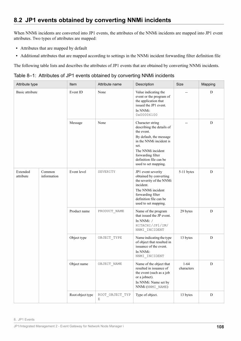
8.2 JP1 events obtained by converting NNMi incidents
When NNMi incidents are converted into JP1 events, the attributes of the NNMi incidents are mapped into JP1 eventattributes. Two types of attributes are mapped:
• Attributes that are mapped by default
• Additional attributes that are mapped according to settings in the NNMi incident forwarding filter definition file
The following table lists and describes the attributes of JP1 events that are obtained by converting NNMi incidents.
Table 8‒1: Attributes of JP1 events obtained by converting NNMi incidents
Attribute type Item Attribute name Description Size Mapping
Basic attribute Event ID None Value indicating theevent or the program ofthe application thatissued the JP1 event.In NNMi:0x00006100
-- D
Message None Character stringdescribing the details ofthe event.By default, the messagein the NNMi incident isset.The NNMi incidentforwarding filterdefinition file can beused to set mapping.
-- D
Extendedattribute
Commoninformation
Event level SEVERITY JP1 event severityobtained by convertingthe severity of the NNMiincident.The NNMi incidentforwarding filterdefinition file can beused to set mapping.
5-11 bytes D
Product name PRODUCT_NAME Name of the programthat issued the JP event.In NNMi: /HITACHI/JP1/IM/NNMI_INCIDENT
29 bytes D
Object type OBJECT_TYPE Name indicating the typeof object that resulted inissuance of the event.In NNMi:NNMI_INCIDENT
13 bytes D
Object name OBJECT_NAME Name of the object thatresulted in issuance ofthe event (such as a jobor a jobnet).In NNMi: Name set byNNMi (NNMI_NAME)
1-64characters
D
Root object type ROOT_OBJECT_TYPE
Type of object. 13 bytes D
8. JP1 Events
JP1/Integrated Management 2 - Event Gateway for Network Node Manager i 108
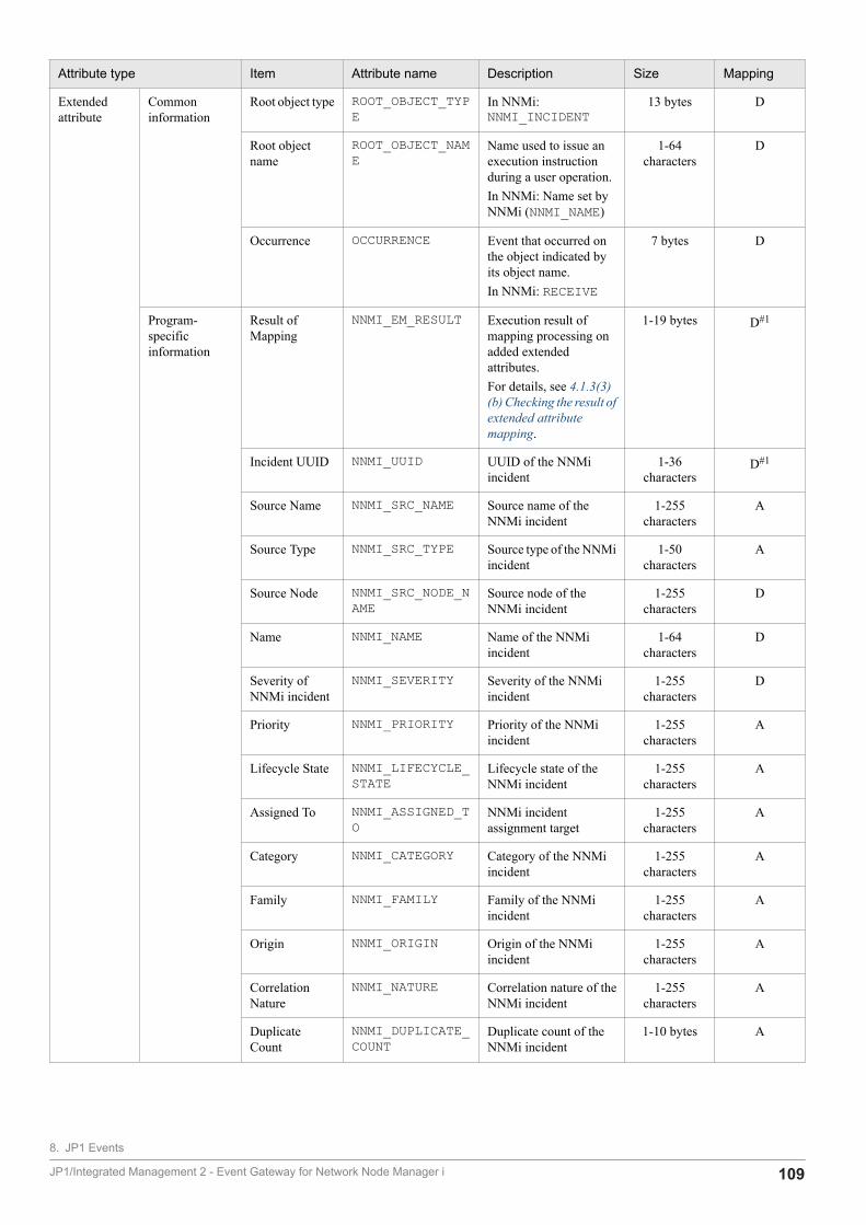
Attribute type Item Attribute name Description Size Mapping
Extendedattribute
Commoninformation
Root object type ROOT_OBJECT_TYPE
In NNMi:NNMI_INCIDENT
13 bytes D
Root objectname
ROOT_OBJECT_NAME
Name used to issue anexecution instructionduring a user operation.In NNMi: Name set byNNMi (NNMI_NAME)
1-64characters
D
Occurrence OCCURRENCE Event that occurred onthe object indicated byits object name.In NNMi: RECEIVE
7 bytes D
Program-specificinformation
Result ofMapping
NNMI_EM_RESULT Execution result ofmapping processing onadded extendedattributes.For details, see 4.1.3(3)(b) Checking the result ofextended attributemapping.
1-19 bytes D#1
Incident UUID NNMI_UUID UUID of the NNMiincident
1-36characters
D#1
Source Name NNMI_SRC_NAME Source name of theNNMi incident
1-255characters
A
Source Type NNMI_SRC_TYPE Source type of the NNMiincident
1-50characters
A
Source Node NNMI_SRC_NODE_NAME
Source node of theNNMi incident
1-255characters
D
Name NNMI_NAME Name of the NNMiincident
1-64characters
D
Severity ofNNMi incident
NNMI_SEVERITY Severity of the NNMiincident
1-255characters
D
Priority NNMI_PRIORITY Priority of the NNMiincident
1-255characters
A
Lifecycle State NNMI_LIFECYCLE_STATE
Lifecycle state of theNNMi incident
1-255characters
A
Assigned To NNMI_ASSIGNED_TO
NNMi incidentassignment target
1-255characters
A
Category NNMI_CATEGORY Category of the NNMiincident
1-255characters
A
Family NNMI_FAMILY Family of the NNMiincident
1-255characters
A
Origin NNMI_ORIGIN Origin of the NNMiincident
1-255characters
A
CorrelationNature
NNMI_NATURE Correlation nature of theNNMi incident
1-255characters
A
DuplicateCount
NNMI_DUPLICATE_COUNT
Duplicate count of theNNMi incident
1-10 bytes A
8. JP1 Events
JP1/Integrated Management 2 - Event Gateway for Network Node Manager i 109
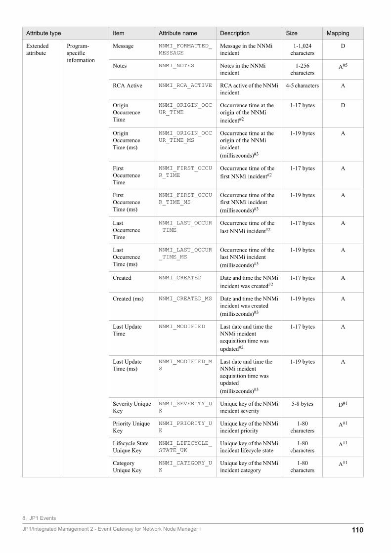
Attribute type Item Attribute name Description Size Mapping
Extendedattribute
Program-specificinformation
Message NNMI_FORMATTED_MESSAGE
Message in the NNMiincident
1-1,024characters
D
Notes NNMI_NOTES Notes in the NNMiincident
1-256characters
A#5
RCA Active NNMI_RCA_ACTIVE RCA active of the NNMiincident
4-5 characters A
OriginOccurrenceTime
NNMI_ORIGIN_OCCUR_TIME
Occurrence time at theorigin of the NNMiincident#2
1-17 bytes D
OriginOccurrenceTime (ms)
NNMI_ORIGIN_OCCUR_TIME_MS
Occurrence time at theorigin of the NNMiincident(milliseconds)#3
1-19 bytes A
FirstOccurrenceTime
NNMI_FIRST_OCCUR_TIME
Occurrence time of thefirst NNMi incident#2
1-17 bytes A
FirstOccurrenceTime (ms)
NNMI_FIRST_OCCUR_TIME_MS
Occurrence time of thefirst NNMi incident(milliseconds)#3
1-19 bytes A
LastOccurrenceTime
NNMI_LAST_OCCUR_TIME
Occurrence time of thelast NNMi incident#2
1-17 bytes A
LastOccurrenceTime (ms)
NNMI_LAST_OCCUR_TIME_MS
Occurrence time of thelast NNMi incident(milliseconds)#3
1-19 bytes A
Created NNMI_CREATED Date and time the NNMiincident was created#2
1-17 bytes A
Created (ms) NNMI_CREATED_MS Date and time the NNMiincident was created(milliseconds)#3
1-19 bytes A
Last UpdateTime
NNMI_MODIFIED Last date and time theNNMi incidentacquisition time wasupdated#2
1-17 bytes A
Last UpdateTime (ms)
NNMI_MODIFIED_MS
Last date and time theNNMi incidentacquisition time wasupdated(milliseconds)#3
1-19 bytes A
Severity UniqueKey
NNMI_SEVERITY_UK
Unique key of the NNMiincident severity
5-8 bytes D#1
Priority UniqueKey
NNMI_PRIORITY_UK
Unique key of the NNMiincident priority
1-80characters
A#1
Lifecycle StateUnique Key
NNMI_LIFECYCLE_STATE_UK
Unique key of the NNMiincident lifecycle state
1-80characters
A#1
CategoryUnique Key
NNMI_CATEGORY_UK
Unique key of the NNMiincident category
1-80characters
A#1
8. JP1 Events
JP1/Integrated Management 2 - Event Gateway for Network Node Manager i 110
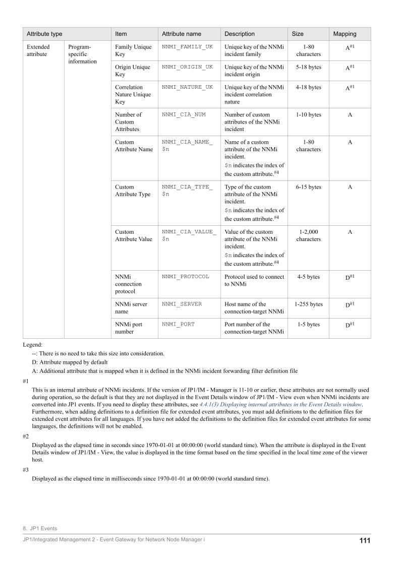
Attribute type Item Attribute name Description Size Mapping
Extendedattribute
Program-specificinformation
Family UniqueKey
NNMI_FAMILY_UK Unique key of the NNMiincident family
1-80characters
A#1
Origin UniqueKey
NNMI_ORIGIN_UK Unique key of the NNMiincident origin
5-18 bytes A#1
CorrelationNature UniqueKey
NNMI_NATURE_UK Unique key of the NNMiincident correlationnature
4-18 bytes A#1
Number ofCustomAttributes
NNMI_CIA_NUM Number of customattributes of the NNMiincident
1-10 bytes A
CustomAttribute Name
NNMI_CIA_NAME_$n
Name of a customattribute of the NNMiincident.$n indicates the index ofthe custom attribute.#4
1-80characters
A
CustomAttribute Type
NNMI_CIA_TYPE_$n
Type of the customattribute of the NNMiincident.$n indicates the index ofthe custom attribute.#4
6-15 bytes A
CustomAttribute Value
NNMI_CIA_VALUE_$n
Value of the customattribute of the NNMiincident.$n indicates the index ofthe custom attribute.#4
1-2,000characters
A
NNMiconnectionprotocol
NNMI_PROTOCOL Protocol used to connectto NNMi
4-5 bytes D#1
NNMi servername
NNMI_SERVER Host name of theconnection-target NNMi
1-255 bytes D#1
NNMi portnumber
NNMI_PORT Port number of theconnection-target NNMi
1-5 bytes D#1
Legend:--: There is no need to take this size into consideration.D: Attribute mapped by defaultA: Additional attribute that is mapped when it is defined in the NNMi incident forwarding filter definition file
#1This is an internal attribute of NNMi incidents. If the version of JP1/IM - Manager is 11-10 or earlier, these attributes are not normally usedduring operation, so the default is that they are not displayed in the Event Details window of JP1/IM - View even when NNMi incidents areconverted into JP1 events. If you need to display these attributes, see 4.4.1(3) Displaying internal attributes in the Event Details window.Furthermore, when adding definitions to a definition file for extended event attributes, you must add definitions to the definition files forextended event attributes for all languages. If you have not added the definitions to the definition files for extended event attributes for somelanguages, the definitions will not be enabled.
#2Displayed as the elapsed time in seconds since 1970-01-01 at 00:00:00 (world standard time). When the attribute is displayed in the EventDetails window of JP1/IM - View, the value is displayed in the time format based on the time specified in the local time zone of the viewerhost.
#3Displayed as the elapsed time in milliseconds since 1970-01-01 at 00:00:00 (world standard time).
8. JP1 Events
JP1/Integrated Management 2 - Event Gateway for Network Node Manager i 111

#4$n is replaced with a number in the range from 1 to the number of custom attributes (NNMI_CIA_NUM). Attributes whose $n is from 1 to 20are displayed in the Event Details window of JP1/IM - View by default. If you want to display attributes whose $n is greater than 20, see4.4.1(4) Displaying custom attributes in the Event Details window.Example: In the case of the fourth custom attribute value, define as NNMI_CIA_VALUE_4.
#5Even when a value is entered into the Notes attribute of an NNMi incident that has been converted into a JP1 event, the attribute value is notmapped into the JP1 event attribute. Only NNMi incident attributes in which values have been entered before JP1/IM - EG for NNMi obtainsNNMi incidents from NNMi can be mapped to JP1 event attributes.
8. JP1 Events
JP1/Integrated Management 2 - Event Gateway for Network Node Manager i 112
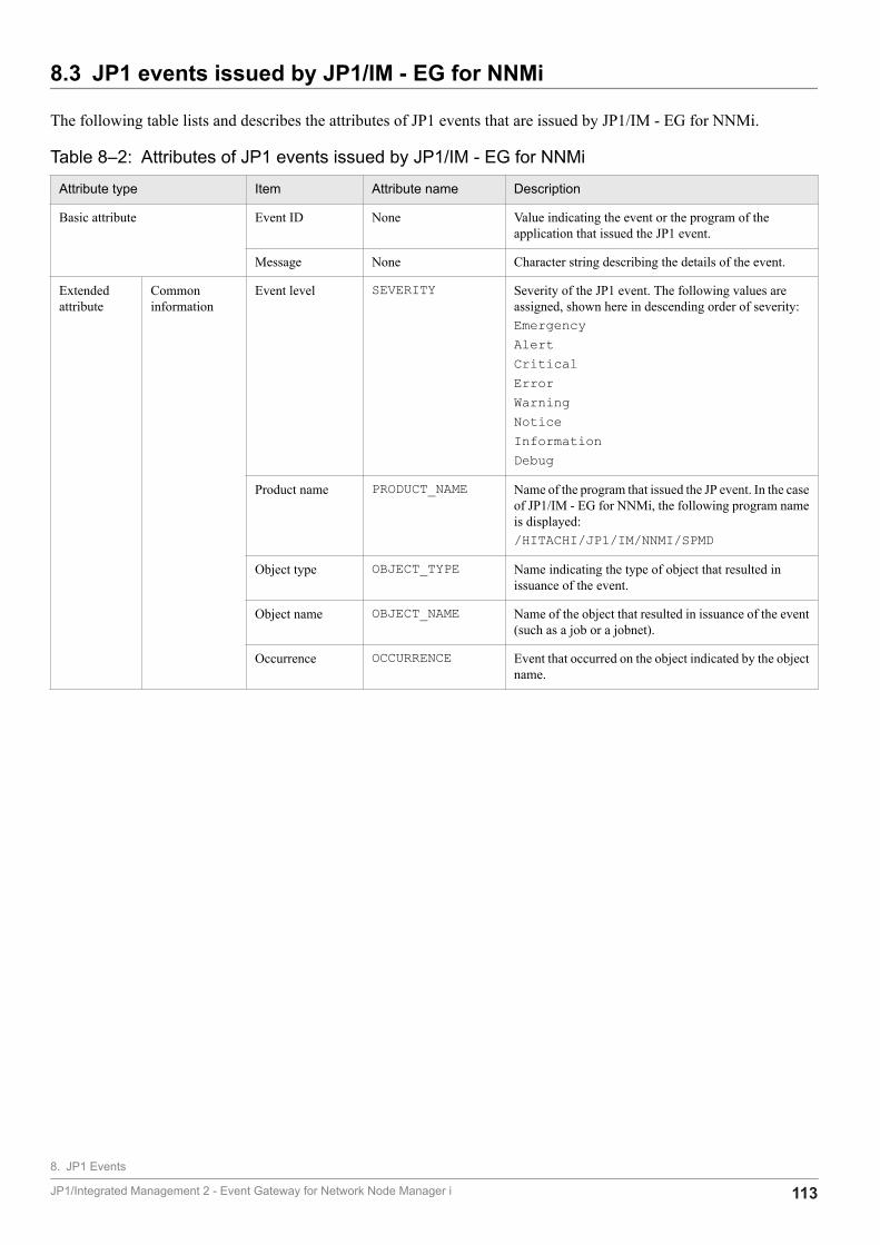
8.3 JP1 events issued by JP1/IM - EG for NNMi
The following table lists and describes the attributes of JP1 events that are issued by JP1/IM - EG for NNMi.
Table 8‒2: Attributes of JP1 events issued by JP1/IM - EG for NNMi
Attribute type Item Attribute name Description
Basic attribute Event ID None Value indicating the event or the program of theapplication that issued the JP1 event.
Message None Character string describing the details of the event.
Extendedattribute
Commoninformation
Event level SEVERITY Severity of the JP1 event. The following values areassigned, shown here in descending order of severity:EmergencyAlertCriticalErrorWarningNoticeInformationDebug
Product name PRODUCT_NAME Name of the program that issued the JP event. In the caseof JP1/IM - EG for NNMi, the following program nameis displayed:/HITACHI/JP1/IM/NNMI/SPMD
Object type OBJECT_TYPE Name indicating the type of object that resulted inissuance of the event.
Object name OBJECT_NAME Name of the object that resulted in issuance of the event(such as a job or a jobnet).
Occurrence OCCURRENCE Event that occurred on the object indicated by the objectname.
8. JP1 Events
JP1/Integrated Management 2 - Event Gateway for Network Node Manager i 113
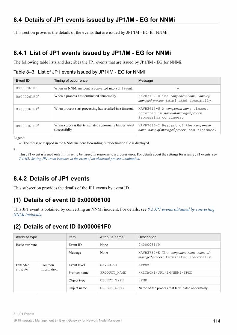
8.4 Details of JP1 events issued by JP1/IM - EG for NNMi
This section provides the details of the events that are issued by JP1/IM - EG for NNMi.
8.4.1 List of JP1 events issued by JP1/IM - EG for NNMiThe following table lists and describes the JP1 events that are issued by JP1/IM - EG for NNMi.
Table 8‒3: List of JP1 events issued by JP1/IM - EG for NNMi
Event ID Timing of occurrence Message
0x00006100 When an NNMi incident is converted into a JP1 event. --
0x000061F0# When a process has terminated abnormally. KAVB3737-E The component-name name-of-managed-process terminated abnormally.
0x000061F1# When process start processing has resulted in a timeout. KAVB3613-W A component-name timeoutoccurred in name-of-managed-process.Processing continues.
0x000061F2# When a process that terminated abnormally has restartedsuccessfully.
KAVB3616-I Restart of the component-name name-of-managed-process has finished.
Legend:--: The message mapped in the NNMi incident forwarding filter definition file is displayed.
#This JP1 event is issued only if it is set to be issued in response to a process error. For details about the settings for issuing JP1 events, see2.4.4(3) Setting JP1 event issuance in the event of an abnormal process termination.
8.4.2 Details of JP1 eventsThis subsection provides the details of the JP1 events by event ID.
(1) Details of event ID 0x00006100This JP1 event is obtained by converting an NNMi incident. For details, see 8.2 JP1 events obtained by convertingNNMi incidents.
(2) Details of event ID 0x000061F0Attribute type Item Attribute name Description
Basic attribute Event ID None 0x000061F0
Message None KAVB3737-E The component-name name-of-managed-process terminated abnormally.
Extendedattribute
Commoninformation
Event level SEVERITY Error
Product name PRODUCT_NAME /HITACHI/JP1/IM/NNMI/SPMD
Object type OBJECT_TYPE SPMD
Object name OBJECT_NAME Name of the process that terminated abnormally
8. JP1 Events
JP1/Integrated Management 2 - Event Gateway for Network Node Manager i 114
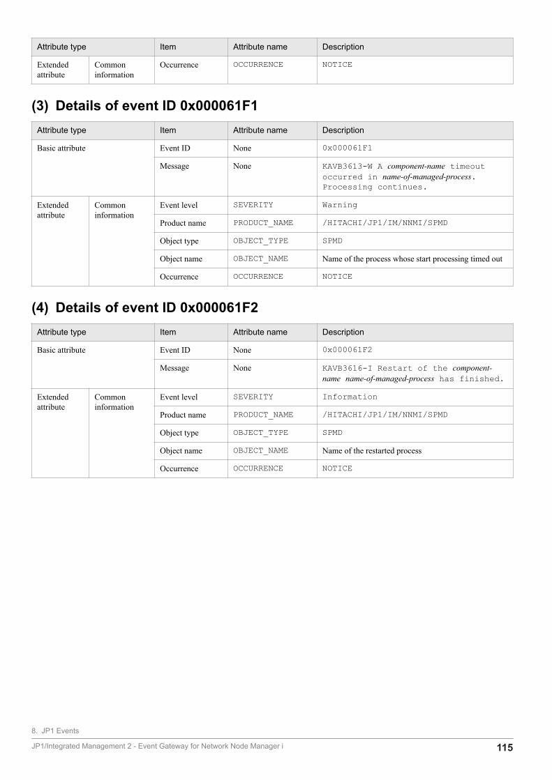
Attribute type Item Attribute name Description
Extendedattribute
Commoninformation
Occurrence OCCURRENCE NOTICE
(3) Details of event ID 0x000061F1Attribute type Item Attribute name Description
Basic attribute Event ID None 0x000061F1
Message None KAVB3613-W A component-name timeoutoccurred in name-of-managed-process.Processing continues.
Extendedattribute
Commoninformation
Event level SEVERITY Warning
Product name PRODUCT_NAME /HITACHI/JP1/IM/NNMI/SPMD
Object type OBJECT_TYPE SPMD
Object name OBJECT_NAME Name of the process whose start processing timed out
Occurrence OCCURRENCE NOTICE
(4) Details of event ID 0x000061F2Attribute type Item Attribute name Description
Basic attribute Event ID None 0x000061F2
Message None KAVB3616-I Restart of the component-name name-of-managed-process has finished.
Extendedattribute
Commoninformation
Event level SEVERITY Information
Product name PRODUCT_NAME /HITACHI/JP1/IM/NNMI/SPMD
Object type OBJECT_TYPE SPMD
Object name OBJECT_NAME Name of the restarted process
Occurrence OCCURRENCE NOTICE
8. JP1 Events
JP1/Integrated Management 2 - Event Gateway for Network Node Manager i 115

9 Messages
This chapter describes the messages that are issued by JP1/IM - EG for NNMi.
JP1/Integrated Management 2 - Event Gateway for Network Node Manager i 116
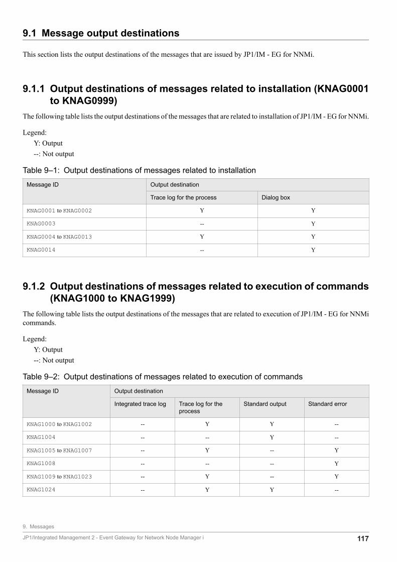
9.1 Message output destinations
This section lists the output destinations of the messages that are issued by JP1/IM - EG for NNMi.
9.1.1 Output destinations of messages related to installation (KNAG0001to KNAG0999)
The following table lists the output destinations of the messages that are related to installation of JP1/IM - EG for NNMi.
Legend:Y: Output--: Not output
Table 9‒1: Output destinations of messages related to installation
Message ID Output destination
Trace log for the process Dialog box
KNAG0001 to KNAG0002 Y Y
KNAG0003 -- Y
KNAG0004 to KNAG0013 Y Y
KNAG0014 -- Y
9.1.2 Output destinations of messages related to execution of commands(KNAG1000 to KNAG1999)
The following table lists the output destinations of the messages that are related to execution of JP1/IM - EG for NNMicommands.
Legend:Y: Output--: Not output
Table 9‒2: Output destinations of messages related to execution of commands
Message ID Output destination
Integrated trace log Trace log for theprocess
Standard output Standard error
KNAG1000 to KNAG1002 -- Y Y --
KNAG1004 -- -- Y --
KNAG1005 to KNAG1007 -- Y -- Y
KNAG1008 -- -- -- Y
KNAG1009 to KNAG1023 -- Y -- Y
KNAG1024 -- Y Y --
9. Messages
JP1/Integrated Management 2 - Event Gateway for Network Node Manager i 117
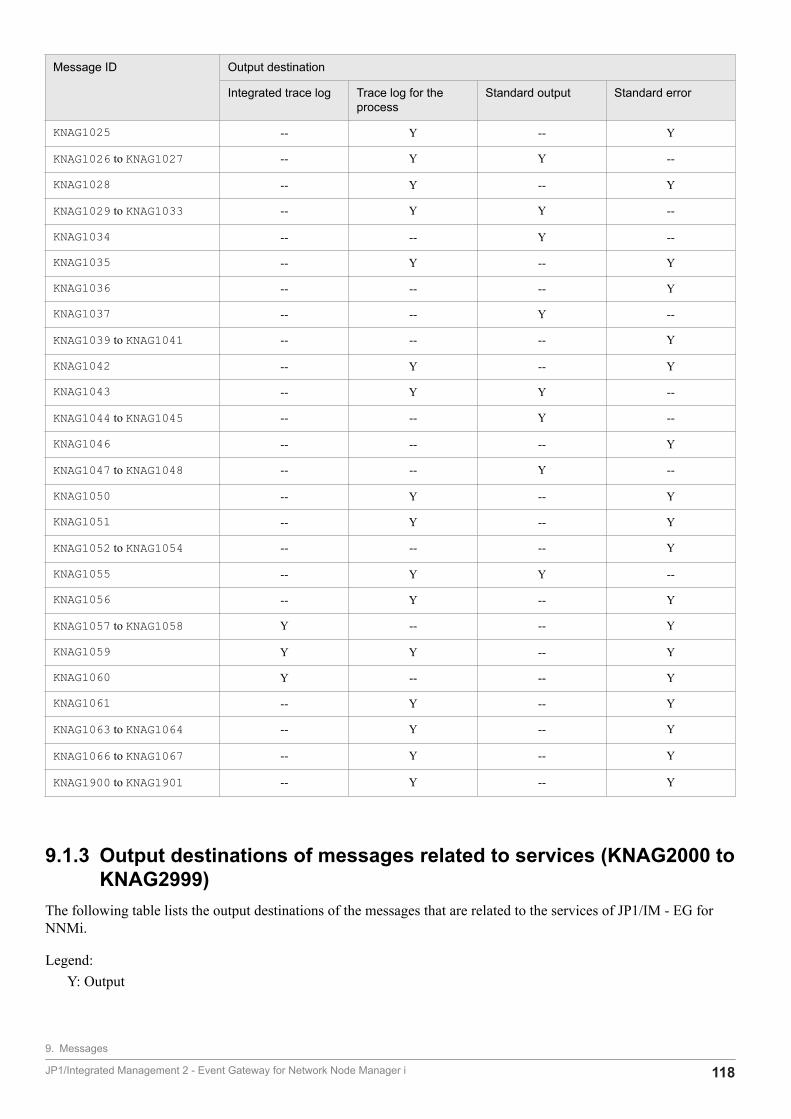
Message ID Output destination
Integrated trace log Trace log for theprocess
Standard output Standard error
KNAG1025 -- Y -- Y
KNAG1026 to KNAG1027 -- Y Y --
KNAG1028 -- Y -- Y
KNAG1029 to KNAG1033 -- Y Y --
KNAG1034 -- -- Y --
KNAG1035 -- Y -- Y
KNAG1036 -- -- -- Y
KNAG1037 -- -- Y --
KNAG1039 to KNAG1041 -- -- -- Y
KNAG1042 -- Y -- Y
KNAG1043 -- Y Y --
KNAG1044 to KNAG1045 -- -- Y --
KNAG1046 -- -- -- Y
KNAG1047 to KNAG1048 -- -- Y --
KNAG1050 -- Y -- Y
KNAG1051 -- Y -- Y
KNAG1052 to KNAG1054 -- -- -- Y
KNAG1055 -- Y Y --
KNAG1056 -- Y -- Y
KNAG1057 to KNAG1058 Y -- -- Y
KNAG1059 Y Y -- Y
KNAG1060 Y -- -- Y
KNAG1061 -- Y -- Y
KNAG1063 to KNAG1064 -- Y -- Y
KNAG1066 to KNAG1067 -- Y -- Y
KNAG1900 to KNAG1901 -- Y -- Y
9.1.3 Output destinations of messages related to services (KNAG2000 toKNAG2999)
The following table lists the output destinations of the messages that are related to the services of JP1/IM - EG forNNMi.
Legend:Y: Output
9. Messages
JP1/Integrated Management 2 - Event Gateway for Network Node Manager i 118
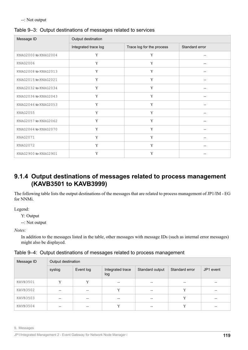
--: Not output
Table 9‒3: Output destinations of messages related to services
Message ID Output destination
Integrated trace log Trace log for the process Standard error
KNAG2000 to KNAG2004 Y Y --
KNAG2006 Y Y --
KNAG2008 to KNAG2013 Y Y --
KNAG2015 to KNAG2021 Y Y --
KNAG2032 to KNAG2034 Y Y --
KNAG2036 to KNAG2043 Y Y --
KNAG2046 to KNAG2053 Y Y --
KNAG2055 Y Y --
KNAG2057 to KNAG2062 Y Y --
KNAG2064 to KNAG2070 Y Y --
KNAG2071 Y Y --
KNAG2072 Y Y --
KNAG2900 to KNAG2901 Y Y --
9.1.4 Output destinations of messages related to process management(KAVB3501 to KAVB3999)
The following table lists the output destinations of the messages that are related to process management of JP1/IM - EGfor NNMi.
Legend:Y: Output--: Not output
Notes:In addition to the messages listed in the table, other messages with message IDs (such as internal error messages)might also be displayed.
Table 9‒4: Output destinations of messages related to process management
Message ID Output destination
syslog Event log Integrated tracelog
Standard output Standard error JP1 event
KAVB3501 Y Y -- -- -- --
KAVB3502 -- -- Y -- Y --
KAVB3503 -- -- -- -- Y --
KAVB3504 -- -- Y -- Y --
9. Messages
JP1/Integrated Management 2 - Event Gateway for Network Node Manager i 119
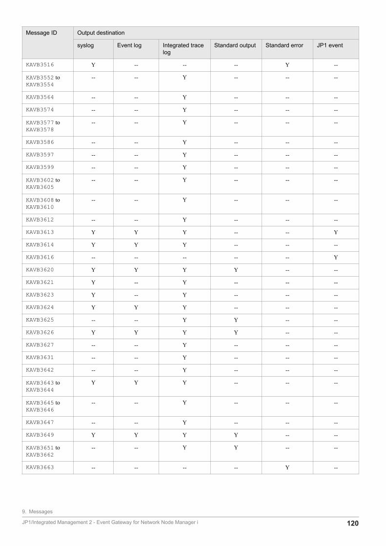
Message ID Output destination
syslog Event log Integrated tracelog
Standard output Standard error JP1 event
KAVB3516 Y -- -- -- Y --
KAVB3552 toKAVB3554
-- -- Y -- -- --
KAVB3564 -- -- Y -- -- --
KAVB3574 -- -- Y -- -- --
KAVB3577 toKAVB3578
-- -- Y -- -- --
KAVB3586 -- -- Y -- -- --
KAVB3597 -- -- Y -- -- --
KAVB3599 -- -- Y -- -- --
KAVB3602 toKAVB3605
-- -- Y -- -- --
KAVB3608 toKAVB3610
-- -- Y -- -- --
KAVB3612 -- -- Y -- -- --
KAVB3613 Y Y Y -- -- Y
KAVB3614 Y Y Y -- -- --
KAVB3616 -- -- -- -- -- Y
KAVB3620 Y Y Y Y -- --
KAVB3621 Y -- Y -- -- --
KAVB3623 Y -- Y -- -- --
KAVB3624 Y Y Y -- -- --
KAVB3625 -- -- Y Y -- --
KAVB3626 Y Y Y Y -- --
KAVB3627 -- -- Y -- -- --
KAVB3631 -- -- Y -- -- --
KAVB3642 -- -- Y -- -- --
KAVB3643 toKAVB3644
Y Y Y -- -- --
KAVB3645 toKAVB3646
-- -- Y -- -- --
KAVB3647 -- -- Y -- -- --
KAVB3649 Y Y Y Y -- --
KAVB3651 toKAVB3662
-- -- Y Y -- --
KAVB3663 -- -- -- -- Y --
9. Messages
JP1/Integrated Management 2 - Event Gateway for Network Node Manager i 120
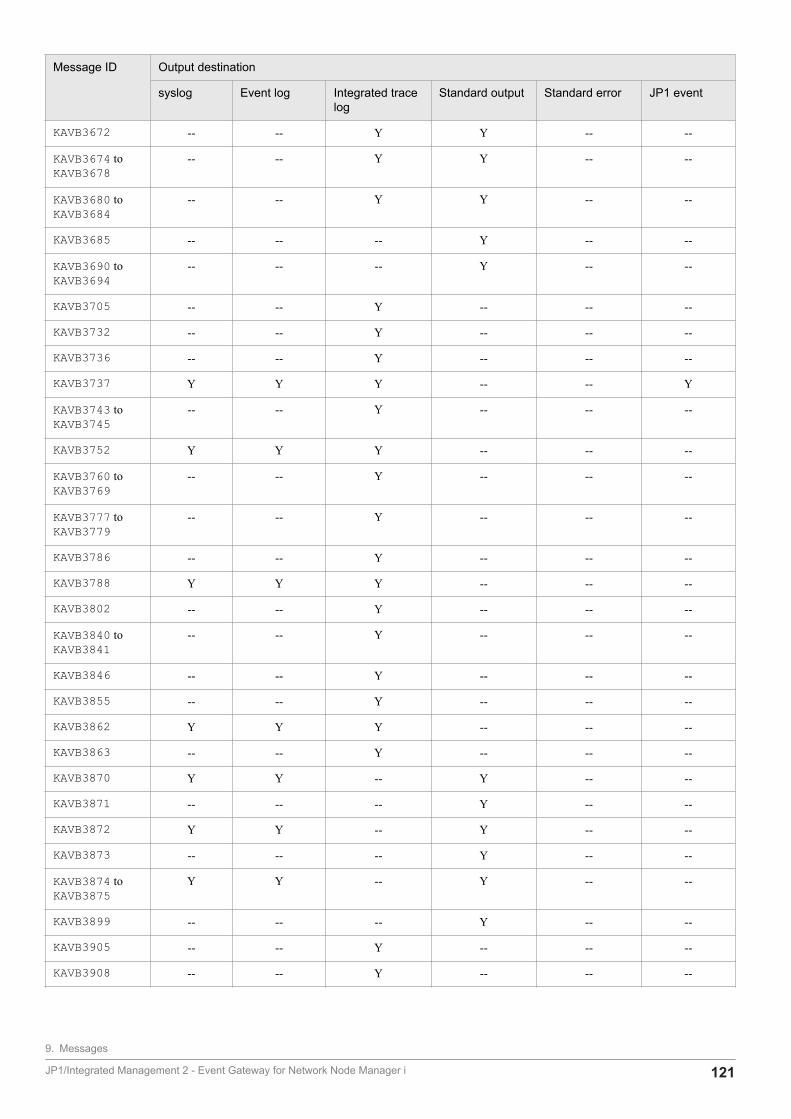
Message ID Output destination
syslog Event log Integrated tracelog
Standard output Standard error JP1 event
KAVB3672 -- -- Y Y -- --
KAVB3674 toKAVB3678
-- -- Y Y -- --
KAVB3680 toKAVB3684
-- -- Y Y -- --
KAVB3685 -- -- -- Y -- --
KAVB3690 toKAVB3694
-- -- -- Y -- --
KAVB3705 -- -- Y -- -- --
KAVB3732 -- -- Y -- -- --
KAVB3736 -- -- Y -- -- --
KAVB3737 Y Y Y -- -- Y
KAVB3743 toKAVB3745
-- -- Y -- -- --
KAVB3752 Y Y Y -- -- --
KAVB3760 toKAVB3769
-- -- Y -- -- --
KAVB3777 toKAVB3779
-- -- Y -- -- --
KAVB3786 -- -- Y -- -- --
KAVB3788 Y Y Y -- -- --
KAVB3802 -- -- Y -- -- --
KAVB3840 toKAVB3841
-- -- Y -- -- --
KAVB3846 -- -- Y -- -- --
KAVB3855 -- -- Y -- -- --
KAVB3862 Y Y Y -- -- --
KAVB3863 -- -- Y -- -- --
KAVB3870 Y Y -- Y -- --
KAVB3871 -- -- -- Y -- --
KAVB3872 Y Y -- Y -- --
KAVB3873 -- -- -- Y -- --
KAVB3874 toKAVB3875
Y Y -- Y -- --
KAVB3899 -- -- -- Y -- --
KAVB3905 -- -- Y -- -- --
KAVB3908 -- -- Y -- -- --
9. Messages
JP1/Integrated Management 2 - Event Gateway for Network Node Manager i 121
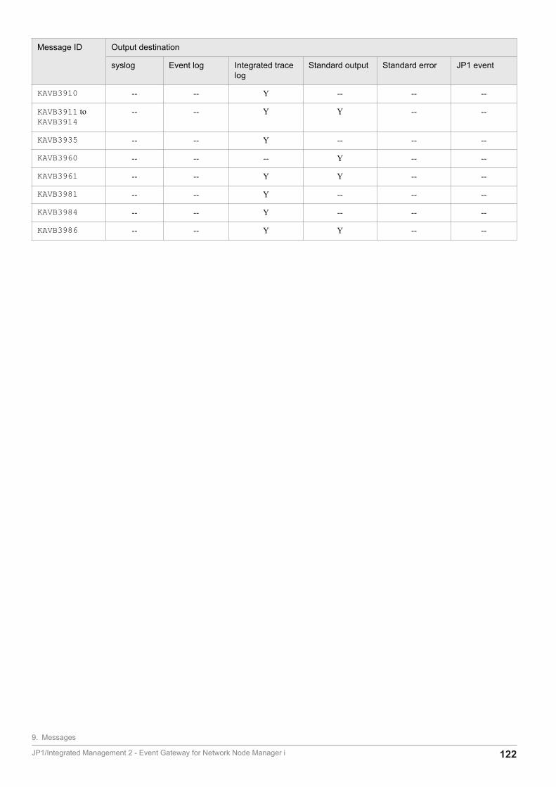
Message ID Output destination
syslog Event log Integrated tracelog
Standard output Standard error JP1 event
KAVB3910 -- -- Y -- -- --
KAVB3911 toKAVB3914
-- -- Y Y -- --
KAVB3935 -- -- Y -- -- --
KAVB3960 -- -- -- Y -- --
KAVB3961 -- -- Y Y -- --
KAVB3981 -- -- Y -- -- --
KAVB3984 -- -- Y -- -- --
KAVB3986 -- -- Y Y -- --
9. Messages
JP1/Integrated Management 2 - Event Gateway for Network Node Manager i 122
9.2 Message format
This section describes the format of messages issued by JP1/IM - EG for NNMi.
9.2.1 Output format of messagesA message consists of a message ID and a message text. The following shows the format of the displayed messages:
KAVBnnnn-Z message-text
KNAGnnnn-Z message-text
The message ID consists of the following components:
KSystem identifier.
AVB or NAGIdentifier of a message as a JP1/IM - EG for NNMi message.
nnnnMessage's serial number.
ZType of message:E: Error message. Processing is canceled.W: Warning message. Processing resumes after the message is displayed.I: Information message. Provides information to the user.Q: Notification message. Requests the user to make a choice regarding execution.
9.2.2 Format of message explanationsThe following shows the format used in this manual to explain the messages.
message-IDmessage-text
Explanation of the message.
S:Indicates the system's processing.
O:Indicates the action that should be taken by the operator when the message is displayed.
9. Messages
JP1/Integrated Management 2 - Event Gateway for Network Node Manager i 123

9.2.3 For system administratorsWhen an error occurs during operation, refer to 10. Troubleshooting, collect the necessary log information, and performan initial investigation.
Perform an initial investigation to identify the cause of an error by checking the OS's log information (event log inWindows, syslog in UNIX) and various log information output by JP1/IM - EG for NNMi. Use this log information todetermine details about the error, how to prevent recurrence of the error, and the appropriate action to be taken.
You need to also record information such as the operational procedure that led to the error and whether the error can bereplicated.
9. Messages
JP1/Integrated Management 2 - Event Gateway for Network Node Manager i 124
9.3 Messages
This section explains messages that have message IDs that are issued by JP1/IM - EG for NNMi.
9.3.1 Messages related to installation (KNAG0001 to KNAG0999)
KNAG0001-EYou do not have the necessary permissions to perform an installation with the current login account. Use anadministrator account. The installation will now be canceled.
The login account does not have the permissions required for installation.
S:Cancels processing.
O:Use an administrator account to perform installation.
KNAG0002-EA prerequisite version of JP1/Base is not installed. The installation will now be canceled.
A prerequisite version of JP1/Base has not been installed.
S:Cancels processing.
O:Install the prerequisite version of JP1/Base.
KNAG0003-WThis platform is not supported. Do you want to cancel the installation?
This message asks whether the processing is to be canceled.
S:Cancels the processing if the Yes button is clicked and resumes processing if the No button is clicked.
O:Install the product on a supported OS.
KNAG0004-EThe installation will be canceled because the service "service-name" is running.
Installation is being canceled because the service is already running.
S:Cancels processing.
9. Messages
JP1/Integrated Management 2 - Event Gateway for Network Node Manager i 125

O:Stop the service and then perform installation.
KNAG0005-EAn attempt to create a file has failed.
An attempt to create a file required for installation failed.
S:Cancels processing.
O:In the case of an overwrite installation or upgrade installation, check that you have write permissions for the foldersand files under the installation folder, and then re-install the product. Otherwise, contact the system administrator.
KNAG0006-EAn attempt to register shared definition information has failed.
An attempt to register common definition information failed.
S:Cancels processing.
O:Use the data collection tool to collect data and then contact the system administrator.
KNAG0007-EThere is not enough memory. Stop any unnecessary applications, and then reattempt the installation.
Installation cannot be performed because of insufficient memory.
S:Cancels processing.
O:Use the data collection tool to collect data and then contact the system administrator.
KNAG0008-EAn attempt to acquire the product information failed because there are not enough resources. (details = function-name, return-value)
An attempt to acquire product information failed because of insufficient resources.
S:Cancels processing.
O:Use the data collection tool to collect data and then contact the system administrator.
9. Messages
JP1/Integrated Management 2 - Event Gateway for Network Node Manager i 126

KNAG0009-EAn attempt to acquire the product information failed because the environment is invalid. (details = character-string, return-value)
An attempt to acquire product information failed because of an invalid environment.
S:Cancels processing.
O:Use the data collection tool to collect data and then contact the system administrator.
KNAG0010-ECode 9999: The media might be defective. Please contact the vendor.
The medium might be defective.
S:Cancels processing.
O:Contact the distributor.
KNAG0011-EAn internal error occurred. Use the data acquisition command to acquire data, and then contact the systemadministrator.
An internal error occurred.
S:Cancels processing.
O:Use the data collection tool to collect data and then contact the system administrator.
KNAG0012-EInformation could not be acquired from the registry.
Information could not be acquired from the registry.
S:Cancels processing.
O:Use the data collection tool to collect data and then contact the system administrator.
KNAG0013-EAn attempt to open a file has failed. Unopened file : file-name
An attempt to open a file has failed.
9. Messages
JP1/Integrated Management 2 - Event Gateway for Network Node Manager i 127

S:Cancels processing.
O:Use the data collection tool to collect data and then contact the system administrator.
KNAG0014-EThis platform is unsupported. Installation will now be cancelled.
This platform is unsupported.
S:Cancels processing.
O:Install the product on a supported OS.
9.3.2 Messages related to execution of commands (KNAG1000 toKNAG1999)
KNAG1000-IThe setup command ended successfully.
The setup command terminated normally.
KNAG1001-IThe cluster setup command ended successfully.
The cluster setup command terminated normally.
KNAG1002-EA folder could not be created on the shared disk.
An attempt to create a folder on the shared disk failed.
S:Cancels command processing.
O:Make sure that the shared disk is accessible.When the shared disk is accessible, re-execute cluster setup of JP1/IM - EG for NNMi.
KNAG1004-IThe cluster setup command will start.
The cluster setup command has executed.
9. Messages
JP1/Integrated Management 2 - Event Gateway for Network Node Manager i 128

KNAG1005-EA command option is invalid.
The format of a command argument is invalid.
S:Cancels command processing.
O:Check and revise the command arguments, as necessary.
KNAG1006-EThe option "option-name" has been duplicated.
The indicated command option was specified more than once.
S:Cancels command processing.
O:Specify the arguments correctly, according to the Usage description that is output after the error message.
KNAG1007-EThe specified logical host "logical-host-name" does not exist.
The specified logical host name does not exist.
S:Cancels command processing.
O:Correct the logical host name specification and then re-execute the data collection tool.
KNAG1008-EA host has not been specified for the -h option.
A host name is missing in the -h option.
S:Cancels command processing.
O:Correct the logical host name specification and then re-execute the data collection tool.
KNAG1009-EThe shared directory "shared-directory-path" used by the specified logical host "logical-host-name" cannot befound.
The shared directory used by the indicated logical host cannot be found.
9. Messages
JP1/Integrated Management 2 - Event Gateway for Network Node Manager i 129

S:Resumes command processing.
O:If the host is at the primary node, mount the shared directory and then re-execute the data collection tool. If the hostis at the secondary node, there is no problem because the shared directory is not mounted.
KNAG1010-EThe specified directory "data-storage-directory-name" is invalid.
The specification of the indicated directory is not valid. The directory might not exist.
S:Cancels command processing.
O:Specify the correct data storage directory and then re-execute the data collection tool.In Windows, check the following:
• The specification does not include a reserved device name (AUX, CON, NUL, PRN, COM1 through COM9, LPT1through LPT9) or any of the symbols ; % & ^ !.
• The length of the specified directory name does not exceed 128 bytes.
KNAG1011-WA file (file-name) with the same name as the directory already exists.
A file with the same name as the directory already exists.
S:Cancels command processing.
O:Delete the file with the same name and then re-execute the data collection tool.
KNAG1012-EThe directory "directory-name" could not be written to.
The execution user does not have the permissions to write to the indicated directory.
S:Cancels command processing.
O:Make sure that the following are true and then re-execute the command:
• The execution user has write permissions for the directory.
• The disk has sufficient capacity.
KNAG1013-WThe directory "directory-path" used by a physical host does not exist.
9. Messages
JP1/Integrated Management 2 - Event Gateway for Network Node Manager i 130

The indicated directory used by the physical host does not exist.
S:Resumes processing without collecting data under the directory path.
O:Make sure that the directory path is not disconnected temporarily.
KNAG1014-EThe command "command-name" does not exist.
The indicated command does not exist.
S:Cancels command processing.
O:Check if the command has been deleted. If the command does not exist, re-install JP1/IM - EG for NNMi.
KNAG1015-WThe command "command-name" does not exist.
The indicated command does not exist.
S:Resumes command processing.
O:Check if the command has been deleted. If the command does not exist, re-install JP1/IM - EG for NNMi.
KNAG1016-EThere is not enough disk space to execute the command.
There is not enough disk space to execute the command.
S:Cancels command processing.
O:Check the available disk space, provide more free space by deleting unneeded files, and then re-execute the datacollection tool. Delete data collected previously by the tool if it still remains on the disk.
KNAG1017-EThere is not enough memory to execute the command.
There is not enough memory to execute the command.
S:Cancels command processing.
9. Messages
JP1/Integrated Management 2 - Event Gateway for Network Node Manager i 131
O:Check the available system memory, provide more memory by terminating unneeded processes, and then re-executethe data collection tool.
KNAG1018-WAn attempt to acquire the Windows event log "type-of-event-log" has failed.
An attempt to collect the Windows event log failed.
type-of-event-log: System or Application
S:Resumes command processing.
O:Use the Event Viewer to collect the Windows event log manually.
KNAG1019-EThe specified file "file-name" cannot be read.
The specified file cannot be read.
S:Cancels command processing.
O:Make sure that you have read permissions for the specified file and then re-execute the command.
KNAG1020-EThe specified file "file-name" does not exist.
The specified file does not exist.
S:Cancels command processing.
O:Specify a file that exists and then re-execute the data collection tool.
KNAG1021-EA file (file-name) with the same name as the directory already exists.
A file with the same name as the specified data storage directory already exists.
S:Cancels command processing.
O:Specify another directory or delete the file with the same name, and then re-execute the data collection tool.
9. Messages
JP1/Integrated Management 2 - Event Gateway for Network Node Manager i 132
KNAG1022-EThe specified directory "directory-name" cannot be written to.
An attempt to write to the specified data storage directory failed.
S:Cancels command processing.
O:Specify another directory, or check and revise (if necessary) the execution user's write permissions for the higherdirectory of the specified directory, and then re-execute the data collection tool.
KNAG1023-EAn attempt to create the directory "directory-name" has failed.
An attempt to create the indicated directory failed.
S:Cancels command processing.
O:Specify another directory, or check and revise (if necessary) the execution user's write permissions for the higherdirectory of the specified directory, and then re-execute the data collection tool.
KNAG1024-IData was successfully acquired.
This message reports that data has been collected successfully.
KNAG1025-ESome of the data could not be acquired.
Some data could not be acquired. This message is displayed after the message that was displayed during execution.
S:Terminates command processing.
O:Take appropriate action according to the information in the message that was displayed during execution.
KNAG1026-I"information" will be acquired.
This message reports that the indicated information is being acquired.
S:Resumes command processing.
9. Messages
JP1/Integrated Management 2 - Event Gateway for Network Node Manager i 133
KNAG1027-I"information" has been acquired.
This message reports that the indicated information has been acquired.
S:Resumes command processing.
KNAG1028-W"information" could not be acquired.
This is a warning message reporting that the indicated information was not acquired.
S:Resumes command processing.
O:If there is data to be collected, collect it manually by referencing 10.3 Data to be collected in the event of an error.
KNAG1029-IThe directory "directory-name" already exists. The directory will be re-created.
The specified directory already exists and will be re-created.
S:In Windows: If the user replies, the system deletes the directory and resumes processing.In UNIX: The system resumes processing.
O:In Windows: To continue the processing, press any key. To cancel the processing, press the Ctrl + C keys.In UNIX: No action is required.
KNAG1030-IThe directory "directory-name" does not exist. The directory will be created.
The indicated directory does not exist and will be created.
S:In Windows: If the user replies, the system creates the directory and resumes processing.In UNIX: The system resumes processing.
O:In Windows: To continue the processing, press any key. To cancel the processing, press the Ctrl + C keys.In UNIX: No action is required.
KNAG1031-IData acquisition will now start.
Data acquisition is starting.
9. Messages
JP1/Integrated Management 2 - Event Gateway for Network Node Manager i 134

S:Resumes command processing.
KNAG1032-IExecution of the command "command-name" will now start.
Execution of the indicated command is starting.
S:Resumes command processing.
KNAG1033-IExecution of the command "command-name" will now end. (error level = error-level)
Execution of the indicated command has ended.
error-level: Command's return code
S:Resumes command processing.
KNAG1034-I"information" will be acquired. Please wait...
The indicated information is being acquired. Wait a while.
S:Resumes command processing.
KNAG1035-EAn attempt to delete the directory "directory-name" has failed.
The attempt to delete the indicated directory failed.
S:Cancels command processing.
O:Make sure that the specified directory is not being used by another process or specify another directory, and thenre-execute the data collection tool.
KNAG1036-EAn attempt to access the information registry has failed. (details = detailed-information)
An attempt to access the indicated information registry failed.
detailed-information: Argument passed to the RegOpenKeyEx/RegEnumKeyEx function and the return code
9. Messages
JP1/Integrated Management 2 - Event Gateway for Network Node Manager i 135

S:Cancels command processing.
O:Contact the system administrator.
KNAG1037-IThe following logical hosts are on this host: logical-host-name To acquire information about a logical host, executethe following command:command-name -f output-directory-name -h logical-host-name
There are one or more logical hosts on this computer.
Execute command-name -h logical-host-name to obtain information about the logical host.
S:Resumes command processing.
O:Execute command-name -h logical-host-name to obtain information about the logical host.
KNAG1039-WAn attempt to create the directory "directory-name" has failed.
The attempt to create the indicated directory failed.
S:Resumes command processing.
O:Check and revise (if necessary) the execution user's write permissions for the higher directory of the specifieddirectory, and then re-execute the data collection tool.
KNAG1040-WAn attempt to execute the command "command-name" has failed. (details = detailed-information)
An attempt to execute the indicated command failed.
detailed-information: Command's return code
S:Resumes command processing.
O:Take appropriate action according to the message that was displayed immediately before this message.
KNAG1041-IThe command "command-name" was successfully executed.
Execution of the indicated command was successful.
9. Messages
JP1/Integrated Management 2 - Event Gateway for Network Node Manager i 136

S:Resumes command processing.
KNAG1042-EYou do not have the permission necessary to execute the command "command-name".
The user does not have the permissions required to execute the indicated command.
S:Cancels command processing.
O:Check the command execution permissions.
KNAG1043-IThe thread dump file has been deleted.
Deletion of the thread dump file has been completed.
S:Resumes command processing.
KNAG1044-IDo you want to delete all the core dump files in the directory "directory-name"? [yes/no]
This is a confirmation message asking whether the core dump files under the indicated directory are to be deleted.
S:If the user enters yes or y, the system deletes the core dump files and then terminates command processing. If theuser enters no or n, the system terminates command processing without deleting the core dump files.
O:To delete the core dump files, enter yes or y. To cancel deletion of the core dump files, enter no or n.
KNAG1045-IDo you want to delete all the thread dump files in the directory "directory-name"? [yes/no]
This is a confirmation message asking whether the thread dump files under the indicated directory are to be deleted.
S:If the user enters yes or y, the system deletes the thread dump files and then terminates command processing. Ifthe user enters no or n, the system terminates command processing without deleting the thread dump files.
O:To delete the thread dump files, enter yes or y. To not delete the thread dump files, enter no or n.
KNAG1046-EThe file cannot be written to because a file with the name "file-name" already exists.
9. Messages
JP1/Integrated Management 2 - Event Gateway for Network Node Manager i 137

A write operation failed because the specified file already exists.
S:Resumes processing without creating a file.
O:Check the write permissions for the file. If the file is not needed, delete it and then re-execute the data collectiontool.
KNAG1047-I"file-name" already exists. Do you want to overwrite it? [yes/no]
This is a configuration message asking whether the indicated file, which already exists, is to be overwritten.
S:If the user enters yes or y, the system overwrites the file and resumes command processing. If the user enters noor n, the system resumes command processing without overwriting the file.
O:To overwrite the file, enter yes or y. To not overwrite the file, enter no or n.
KNAG1048-IIs the device "device-name" ready? [yes/no]
This is a confirmation message asking whether the device is ready.
S:If the user enters yes or y, the system performs data collection on the device and then resumes command processing.If the user enters no or n, the system resumes command processing without performing data collection on the device.
O:To perform data collection on the device, enter yes or y. To not perform data collection on the device, enter no orn.
KNAG1050-EThe value of the option "option-name" is invalid.
The specified option value is invalid.
S:Cancels command processing.
O:Check and revise (if necessary) the option value and then re-execute the command.
KNAG1051-ESetup has not been performed yet.
The -list or the -update option cannot be specified before setup has been completed.
9. Messages
JP1/Integrated Management 2 - Event Gateway for Network Node Manager i 138
S:Cancels command processing.
O:Execute new setup and then re-execute the command.
KNAG1052-EThe operation information file "file-name" already exists.
The shared directory specified in the -d option of the jegn_setup_cluster command already contains theoperation information file.
S:Cancels command processing.
O:Either delete the existing operation information file or change the shared directory, and then re-execute the command.
KNAG1053-EThe file "file-name" could not be written to.
An attempt to write to the indicated file failed because the execution user did not have the required permissions.
S:Cancels command processing.
O:Check and revise (if necessary) the execution user's write permissions for the file and then re-execute the command.
KNAG1054-EAn attempt to update the registry information "registry-key" has failed.
An attempt to update the indicated registry information (such as common definition information or service registration)has failed.
S:Cancels command processing.
O:Use the data collection tool to collect data and then contact the system administrator.
KNAG1055-IThe core dump file "file-name" has been successfully deleted.
Deletion of the core dump file has been completed.
S:Resumes command processing.
9. Messages
JP1/Integrated Management 2 - Event Gateway for Network Node Manager i 139

KNAG1056-ESetup has already been performed.
Setup has already been performed, but an attempt was made to perform a new setup.
S:Cancels command processing.
O:Use the -list option to check the settings, specify the -update option and the options whose settings are to bechanged, and then re-execute the command.
KNAG1057-EAdministrator permissions are required to execute the command.
This command must be executed by a user who has Administrator permissions.
S:Cancels command processing.
O:Check that the user has the Administrator permissions and then re-execute the command.
KNAG1058-EExecute the command from the administrator console.
This command must be executed at the administrator console.
S:Cancels command processing.
O:Re-execute the command at the administrator console.
KNAG1059-EThe system environment is invalid. (location, reason-code)
The command cannot be executed because the system environment is invalid.
S:Cancels command processing.
O:Execute installation and setup again.
KNAG1060-EAn attempt to open a message file has failed.
An attempt to open a message file failed.
9. Messages
JP1/Integrated Management 2 - Event Gateway for Network Node Manager i 140
S:Cancels command processing.
O:
In Windows:Use the data collection tool to collect data and then contact the system administrator.
In UNIX:Possible causes are listed below. Check the environment.
• The user might not have read permissions for the files under /opt/jp1eg4nnmi/lib/nls. Grant theread permissions.
• The number of open files might have reached the maximum permitted in the system. If necessary, revise thekernel parameter.
• A temporary memory shortage might have occurred. Re-execute the command. Or, terminate any unneededprocess.
• The directory or file might have been deleted. Re-install it.
If the problem cannot be resolved, use the data collection tool to collect data and then contact the systemadministrator.
KNAG1061-EThe specified logical host name is invalid.
The specified logical host name is invalid.
S:Cancels command processing.
O:Check and revise (if necessary) the logical host name or specify the correct logical host name, and then re-executethe command.
KNAG1063-EAn attempt to register shared definition information has failed.
An attempt to register common definition information failed.
S:Cancels command processing.
O:Use the data collection tool to collect data and then contact the system administrator.
KNAG1064-EThe logical host name specified for the argument does not exist.
The logical host specified in the argument does not exist.
S:Cancels command processing.
9. Messages
JP1/Integrated Management 2 - Event Gateway for Network Node Manager i 141

O:Check if the specified logical host was set correctly.
KNAG1066-EA setting in the shared definition information is invalid.
A setting in the common definition information is invalid.
S:Cancels command processing.
O:Make sure that the common definition information set at the primary node has been migrated to the secondary node,and then re-execute the jegn_setup_cluster command.
KNAG1067-EAn attempt to create the file "file-name" has failed.
An attempt to create the indicated file failed.
S:Cancels command processing.
O:Use the data collection tool to collect data and then contact the system administrator.
KNAG1900-EThere is not enough memory. (maintenance-information)
A memory shortage has occurred.
S:Cancels command processing.
O:Use the data collection tool to collect data and then contact the system administrator.
KNAG1901-EA system error occurred. (maintenance-information)
A system error occurred.
S:Cancels command processing.
O:Use the data collection tool to collect data and then contact the system administrator.
9. Messages
JP1/Integrated Management 2 - Event Gateway for Network Node Manager i 142
9.3.3 Messages related to services (KNAG2000 to KNAG2999)
KNAG2000-IThe JP1/IM-EG for NNMi service has started. (logical host name = logical-host-name)
The JP1/IM - EG for NNMi service has started.
In the case of the physical host, JP1_DEFAULT is displayed as the logical host name.
S:The system started the JP1/IM - EG for NNMi service.
KNAG2001-EAn attempt to start the JP1/IM-EG for NNMi service has failed. (logical host name = logical-host-name)
An attempt to start the JP1/IM - EG for NNMi service has failed.
In the case of the physical host, JP1_DEFAULT is displayed as the logical host name.
S:An attempt by the system to start the JP1/IM - EG for NNMi service has failed.
O:Check the immediately preceding error message, eliminate the cause of the error, and then start the service again.
KNAG2002-ESetup has not been performed yet.
An attempt to start the JP1/IM - EG for NNMi service has failed because the setup command (jegn_setup) has notbeen executed.
S:An attempt by the system to start the JP1/IM - EG for NNMi service has failed.
O:Execute the setup command (jegn_setup), make sure that setup is completed successfully, and then re-executethe command to start the service.
KNAG2003-IThe JP1/IM-EG for NNMi service has stopped. (logical host name = logical-host-name)
The JP1/IM - EG for NNMi service has stopped.
In the case of the physical host, JP1_DEFAULT is displayed as the logical host name.
S:The system stopped the JP1/IM - EG for NNMi service.
9. Messages
JP1/Integrated Management 2 - Event Gateway for Network Node Manager i 143
KNAG2004-EAn attempt to stop the JP1/IM-EG for NNMi service has failed. (logical host name = logical-host-name)
An attempt to stop the JP1/IM - EG for NNMi service has failed.
In the case of the physical host, JP1_DEFAULT is displayed as the logical host name.
S:An attempt by the system to stop the JP1/IM - EG for NNMi service has failed.
O:Check the immediately preceding error message, eliminate the cause of the error, and then re-execute the commandto stop the service.
KNAG2006-EThe JP1/IM-EG for NNMi service ended abnormally. (logical host name = logical-host-name)
The JP1/IM - EG for NNMi service terminated abnormally.
In the case of the physical host, JP1_DEFAULT is displayed as the logical host name.
S:The system terminated the JP1/IM - EG for NNMi service abnormally.
O:Use the data collection tool to collect data and then contact the system administrator.
KNAG2008-EAn attempt to read the forwarded NNMi incident information file has failed.
An attempt to read the NNMi incident forwarding information file resulted in an error.
S:Stops the JP1/IM - EG for NNMi service.
O:Use the data collection tool to collect data and then contact the system administrator.
KNAG2009-EThe file size of the forwarded NNMi incident information file has exceeded the limit (file-size).
The size of the NNMi incident forwarding information file exceeds the maximum size.
S:Stops the JP1/IM - EG for NNMi service.
O:Use the data collection tool to collect data and then contact the system administrator.
9. Messages
JP1/Integrated Management 2 - Event Gateway for Network Node Manager i 144
KNAG2010-EAn invalid item key has been specified. (line = line-number, item key = item-key-name)
The transferred NNMi incident information file contains an invalid item key.
S:Stops the JP1/IM - EG for NNMi service.
O:Use the data collection tool to collect data and then contact the system administrator.
KNAG2011-EAn invalid value has been specified. (line = line-number, item key = item-key-name, value = item-value)
An invalid value is specified for the item key in the transferred NNMi incident information file.
S:Stops the JP1/IM - EG for NNMi service.
O:Use the data collection tool to collect data and then contact the system administrator.
KNAG2012-EAn item key has been duplicated. (line = line-number, item key = item-key-name)
The same item key is specified more than once in the transferred NNMi incident information file.
S:Stops the JP1/IM - EG for NNMi service.
O:Use the data collection tool to collect data and then contact the system administrator.
KNAG2013-EThe format is invalid. (line = line-number)
The transferred NNMi incident information file contains a line in an invalid format.
S:Stops the JP1/IM - EG for NNMi service.
O:Use the data collection tool to collect data and then contact the system administrator.
KNAG2015-EAn attempt to read the action definition file has failed.
An attempt to read the operation definition file resulted in an error.
9. Messages
JP1/Integrated Management 2 - Event Gateway for Network Node Manager i 145
S:
• When the JP1/IM - EG for NNMi service is running: The system stops the JP1/IM - EG for NNMi service.
• When the jegn_spmd_reload command is executing: The system resumes processing using the unupdatedinformation.
O:Use the data collection tool to collect data and then contact the system administrator.
KNAG2016-EThe file size of the action definition file has exceeded the limit (file-size).
The size of the operation definition file has exceeded the maximum value.
S:Stops the JP1/IM - EG for NNMi service.
O:Use the data collection tool to collect data and then contact the system administrator.
KNAG2017-EAn invalid item key has been specified. (line = line-number, item key = item-key-name)
The operation definition file contains an invalid item key.
S:
• When the JP1/IM - EG for NNMi service is running: The system stops the JP1/IM - EG for NNMi service.
• When the jegn_spmd_reload command is executing: The system resumes processing using the unupdatedinformation.
O:Use the data collection tool to collect data and then contact the system administrator.
KNAG2018-EAn invalid value has been specified. (line = line-number, item key = item-key-name, value = item-value)
An invalid value is specified for an item key in the operation definition file.
S:
• When the JP1/IM - EG for NNMi service is running: The system stops the JP1/IM - EG for NNMi service.
• When the jegn_spmd_reload command is executing: The system resumes processing using the unupdatedinformation.
O:Use the data collection tool to collect data and then contact the system administrator.
KNAG2019-EA required item key has not been specified. (item key = item-key-name)
A required item key is missing in the operation definition file.
9. Messages
JP1/Integrated Management 2 - Event Gateway for Network Node Manager i 146
S:
• When the JP1/IM - EG for NNMi service is running: The system stops the JP1/IM - EG for NNMi service.
• When the jegn_spmd_reload command is executing: The system resumes processing using the unupdatedinformation.
O:Use the data collection tool to collect data and then contact the system administrator.
KNAG2020-EAn item key has been duplicated. (line = line-number, item key = item-key-name)
The same item is specified more than once in the operation definition file.
S:
• When the JP1/IM - EG for NNMi service is running: The system stops the JP1/IM - EG for NNMi service.
• When the jegn_spmd_reload command is executing: The system resumes processing using the unupdatedinformation.
O:Use the data collection tool to collect data and then contact the system administrator.
KNAG2021-EThe format is invalid. (line = line-number)
The operation definition file contains a line in an invalid format.
S:
• When the JP1/IM - EG for NNMi service is running: The system stops the JP1/IM - EG for NNMi service.
• When the jegn_spmd_reload command is executing: The system resumes processing using the unupdatedinformation.
O:Use the data collection tool to collect data and then contact the system administrator.
KNAG2032-EAn attempt to connect to the NNMi server has failed. (NNMi server name = NNMi-server-name)
An attempt to connect to the NNMi server failed.
S:After the NNMI incident re-acquisition interval specified in the jegn_setup command has elapsed, the systemwill attempt to connect to the NNMi server again.
O:Check that the NNMi server is running.In the NNMi server is running, check the NNMi port number specified in the jegn_setup command for anyerrors. If the specified information is not correct, re-execute the jegn_setup command with the correctinformation specified, and then execute the jegn_spmd_reload command.
9. Messages
JP1/Integrated Management 2 - Event Gateway for Network Node Manager i 147
KNAG2033-EAn attempt to authenticate the NNMi server has failed. (NNMi server name = NNMi-server-name)
NNMi server authentication has failed.
S:After the NNMI incident re-acquisition interval specified in the jegn_setup command has elapsed, the systemwill attempt to connect to the NNMi server again.
O:Check that the NNMi server is running.In the NNMi server is running, check the NNMi user name and password specified in the jegn_setup commandfor any errors. If the specified information is not correct, re-execute the jegn_setup command with the correctinformation specified, and then execute the jegn_spmd_reload command.
KNAG2034-EAn attempt to analyze an NNMi incident has failed. (maintenance-information)
Analysis of an NNMi incident has failed.
S:After the NNMI incident re-acquisition interval specified in the jegn_setup command has elapsed, the systemwill connect to the NNMi server again in order to acquire NNMi incidents.
O:Use the data collection tool to collect data and then contact the system administrator.
KNAG2036-EAn attempt to read the forwarded NNMi incident information file has failed.
An attempt to read the NNMi incident forwarding filter definition file resulted in an error.
S:
• When the JP1/IM - EG for NNMi service is running: The system stops the JP1/IM - EG for NNMi service.
• When the jegn_spmd_reload command is executing: The system resumes processing using the unupdatedinformation.
O:Use the data collection tool to collect data and then contact the system administrator.
KNAG2037-EThe file size of the forwarded NNMi incident information file has exceeded the limit (file-size).
The size of the NNMi incident forwarding filter definition file has exceeded the maximum size.
S:
• When the JP1/IM - EG for NNMi service is running: The system stops the JP1/IM - EG for NNMi service.
• When the jegn_spmd_reload command is executing: The system resumes processing using the unupdatedinformation.
9. Messages
JP1/Integrated Management 2 - Event Gateway for Network Node Manager i 148
O:Check the NNMi incident forwarding filter definition file and correct its size so that it does not exceed the maximum.Then start the service or re-execute the jegn_spmd_reload command.
KNAG2038-EThe number of exclusion condition blocks has exceeded the limit (maximum-value).
The number of forwarding condition blocks in the NNMi incident forwarding filter definition file has exceeded themaximum.
S:
• When the JP1/IM - EG for NNMi service is running: The system stops the JP1/IM - EG for NNMi service.
• When the jegn_spmd_reload command is executing: The system resumes processing using the unupdatedinformation.
O:Revise the NNMi incident forwarding filter definition file so that the number of forwarding condition blocks doesnot exceed the maximum. Then start the service or re-execute the jegn_spmd_reload command.
KNAG2039-EAn exclusion condition block has been duplicated. (line = line-number)
An exclusion condition block is duplicated in the NNMi incident forwarding filter definition file.
S:
• When the JP1/IM - EG for NNMi service is running: The system stops the JP1/IM - EG for NNMi service.
• When the jegn_spmd_reload command is executing: The system resumes processing using the unupdatedinformation.
O:Check the line indicated by line-number in the message and correct the NNMi incident forwarding filter definitionfile. Then start the service or re-execute the jegn_spmd_reload command.
KNAG2040-EAn invalid item key has been specified. (line = line-number, item key = item-key-name)
The NNMi incident forwarding filter definition file contains an invalid item key.
S:
• When the JP1/IM - EG for NNMi service is running: The system stops the JP1/IM - EG for NNMi service.
• When the jegn_spmd_reload command is executing: The system resumes processing using the unupdatedinformation.
O:Check the item key indicated by line-number and item-key-name in the message, and correct the NNMi incidentforwarding filter definition file. Then start the service or re-execute the jegn_spmd_reload command.
9. Messages
JP1/Integrated Management 2 - Event Gateway for Network Node Manager i 149
KNAG2041-EAn invalid operator has been specified. (line = line-number, operator = operator-name)
The NNMi incident forwarding filter definition file contains an invalid operator.
S:
• When the JP1/IM - EG for NNMi service is running: The system stops the JP1/IM - EG for NNMi service.
• When the jegn_spmd_reload command is executing: The system resumes processing using the unupdatedinformation.
O:Check the operator indicated by line-number and operator-name in the message, and correct the NNMi incidentforwarding filter definition file. Then start the service or re-execute the jegn_spmd_reload command.
KNAG2042-EThe number of operands is invalid. (line = line-number, operator = operator-name, number of operands = operands-count)
The number of operands in a conditional statement is invalid in the NNMi incident forwarding filter definition file.
S:
• When the JP1/IM - EG for NNMi service is running: The system stops the JP1/IM - EG for NNMi service.
• When the jegn_spmd_reload command is executing: The system resumes processing using the unupdatedinformation.
O:Check the operand indicated by line-number and operator-name in the message, and correct the NNMi incidentforwarding filter definition file. Then start the service or re-execute the jegn_spmd_reload command.
KNAG2043-EAn invalid operand has been specified. (line = line-number, operator = operator-name)
An operand is invalid in the NNMi incident forwarding filter definition file.
S:
• When the JP1/IM - EG for NNMi service is running: The system stops the JP1/IM - EG for NNMi service.
• When the jegn_spmd_reload command is executing: The system resumes processing using the unupdatedinformation.
O:Check the operand indicated by line-number and operator-name in the message, and correct the NNMi incidentforwarding filter definition file. Then start the service or re-execute the jegn_spmd_reload command.
KNAG2046-EThe message mapping definition has been duplicated. (line = line-number)
The message mapping definition is duplicated in the NNMi incident forwarding filter definition file
9. Messages
JP1/Integrated Management 2 - Event Gateway for Network Node Manager i 150
S:
• When the JP1/IM - EG for NNMi service is running: The system stops the JP1/IM - EG for NNMi service.
• When the jegn_spmd_reload command is executing: The system resumes processing using the unupdatedinformation.
O:Check the line indicated by line-number in the message and delete the duplicate message mapping definition. Thenstart the service or re-execute the jegn_spmd_reload command.
KNAG2047-EAn invalid item key has been specified in the message mapping definition. (line = line-number, item key = item-key-name)
The message mapping definition in the NNMi incident forwarding filter definition file contains an invalid item keyname.
S:
• When the JP1/IM - EG for NNMi service is running: The system stops the JP1/IM - EG for NNMi service.
• When the jegn_spmd_reload command is executing: The system resumes processing using the unupdatedinformation.
O:Check the item key indicated by line-number and item-key-name in the message, and correct the item key. Then startthe service or re-execute the jegn_spmd_reload command.
KNAG2048-EThe severity-level mapping definition has been duplicated. (line = line-number)
The severity-level mapping definition is duplicated in the NNMi incident forwarding filter definition file.
S:
• When the JP1/IM - EG for NNMi service is running: The system stops the JP1/IM - EG for NNMi service.
• When the jegn_spmd_reload command is executing: The system resumes processing using the unupdatedinformation.
O:Check the line indicated by line-number in the message and delete the duplicate severity-level mapping definition.Then start the service or re-execute the jegn_spmd_reload command.
KNAG2049-EAn invalid item key has been specified in the severity level mapping definition. (line = line-number, item key =item-key-name)
The severity-level mapping definition in the NNMi incident forwarding filter definition file contains an invalid itemkey name.
S:
• When the JP1/IM - EG for NNMi service is running: The system stops the JP1/IM - EG for NNMi service.
9. Messages
JP1/Integrated Management 2 - Event Gateway for Network Node Manager i 151
• When the jegn_spmd_reload command is executing: The system resumes processing using the unupdatedinformation.
O:Check the item key indicated by line-number and item-key-name in the message, and correct the item key. Then startthe service or re-execute the jegn_spmd_reload command.
KNAG2050-EAn extended attribute mapping definition has been duplicated. (line = line-number)
An extended attribute mapping definition is duplicated in the NNMi incident forwarding filter definition file.
S:
• When the JP1/IM - EG for NNMi service is running: The system stops the JP1/IM - EG for NNMi service.
• When the jegn_spmd_reload command is executing: The system resumes processing using the unupdatedinformation.
O:Check the line indicated by line-number in the message and delete the duplicate extended attribute mappingdefinition. Then start the service or re-execute the jegn_spmd_reload command.
KNAG2051-EAn invalid item key has been specified in an extended attribute mapping definition. (line = line-number, item key= item-key-name)
The extended attribute mapping definition in the NNMi incident forwarding filter definition file contains an invalid itemkey name.
S:
• When the JP1/IM - EG for NNMi service is running: The system stops the JP1/IM - EG for NNMi service.
• When the jegn_spmd_reload command is executing: The system resumes processing using the unupdatedinformation.
O:Check the item key indicated by line-number and item-key-name in the message, and then correct the item key. Thenstart the service or re-execute the jegn_spmd_reload command.
KNAG2052-EAn item key has been duplicated in an extended attribute mapping definition. (line = line-number, item key = item-key-name)
An item key specified in an extended attribute mapping definition is duplicated in the NNMi incident forwarding filterdefinition file.
S:
• When the JP1/IM - EG for NNMi service is running: The system stops the JP1/IM - EG for NNMi service.
• When the jegn_spmd_reload command is executing: The system resumes processing using the unupdatedinformation.
9. Messages
JP1/Integrated Management 2 - Event Gateway for Network Node Manager i 152
O:Check the item key indicated by line-number and item-key-name in the message, and delete the duplicate item key.Then start the service or re-execute the jegn_spmd_reload command.
KNAG2053-EThe format is invalid. (line = line-number)
The NNMi incident forwarding filter definition file contains a line with an invalid format.
S:
• When the JP1/IM - EG for NNMi service is running: The system stops the JP1/IM - EG for NNMi service.
• When the jegn_spmd_reload command is executing: The system resumes processing using the unupdatedinformation.
O:Check the line indicated by line-number in the message and correct the NNMi incident forwarding filter definitionfile. Then start the service or re-execute the jegn_spmd_reload command.
KNAG2055-EAn attempt to register a JP1 event failed. (maintenance-information)
An attempt to register a JP1 event resulted in an error.
S:Cancels the JP1 event registration processing. When the NNMI incident re-acquisition interval specified in thejegn_setup command has elapsed, the system attempts again to acquire NNMi incidents and perform JP1 eventissuance processing.
O:Use the data collection tool to collect data and then contact the system administrator.
KNAG2057-EAn attempt to read the category-label mapping file has failed.
An attempt to read the mapping definition file (for category) resulted in an error.
S:
• When the JP1/IM - EG for NNMi service is running: The system stops the JP1/IM - EG for NNMi service.
• When the jegn_spmd_reload command is executing: The system resumes processing using the unupdatedinformation.
O:Use the data collection tool to collect data and then contact the system administrator.
KNAG2058-EThe file size of the category-label mapping file has exceeded the limit (file-size).
The size of the mapping definition file (for category) has exceeded the maximum size.
9. Messages
JP1/Integrated Management 2 - Event Gateway for Network Node Manager i 153
S:
• When the JP1/IM - EG for NNMi service is running: The system stops the JP1/IM - EG for NNMi service.
• When the jegn_spmd_reload command is executing: The system resumes processing using the unupdatedinformation.
O:Check the mapping definition file (for category) and revise it so that the maximum size is not exceeded. Then startthe service or re-execute the jegn_spmd_reload command.
KNAG2059-EAn invalid key has been specified. (line = line-number, item key = key-name)
An invalid key is specified in the mapping definition file (for category).
S:
• When the JP1/IM - EG for NNMi service is running: The system stops the JP1/IM - EG for NNMi service.
• When the jegn_spmd_reload command is executing: The system resumes processing using the unupdatedinformation.
O:Check the key indicated by line-number and key-name in the message, and then correct the mapping definition file(for categories). Then start the service or re-execute the jegn_spmd_reload command.
KNAG2060-EAn invalid display name has been specified. (line = line-number, item key = key-name, display name = display-name)
An invalid display name (label) is specified in the mapping definition file (for category).
S:
• When the JP1/IM - EG for NNMi service is running: The system stops the JP1/IM - EG for NNMi service.
• When the jegn_spmd_reload command is executing: The system resumes processing using the unupdatedinformation.
O:Check the display name indicated by line-number, key-name, and display-name in the message, and then correct themapping definition file (for category). Then start the service or re-execute the jegn_spmd_reload command.
KNAG2061-EKeys have been duplicated. (line = line-number, key = key-name)
The same key is specified more than once in the mapping definition file (for category).
S:
• When the JP1/IM - EG for NNMi service is running: The system stops the JP1/IM - EG for NNMi service.
• When the jegn_spmd_reload command is executing: The system resumes processing using the unupdatedinformation.
9. Messages
JP1/Integrated Management 2 - Event Gateway for Network Node Manager i 154
O:Check the key indicated by line-number and key-name in the message, and then correct the mapping definition file(for category). Then start the service or re-execute the jegn_spmd_reload command.
KNAG2062-EThe format is invalid. (line = line-number)
The mapping definition file (for category) contains a line with an invalid format.
S:
• When the JP1/IM - EG for NNMi service is running: The system stops the JP1/IM - EG for NNMi service.
• When the jegn_spmd_reload command is executing: The system resumes processing using the unupdatedinformation.
O:Check the line indicated by line-number in the message and correct the mapping definition file (category). Thenstart the service or re-execute the jegn_spmd_reload command.
KNAG2064-EAn attempt to read the family-label mapping file has failed.
An attempt to read the mapping definition file (for family) resulted in an error.
S:
• When the JP1/IM - EG for NNMi service is running: The system stops the JP1/IM - EG for NNMi service.
• When the jegn_spmd_reload command is executing: The system resumes processing using the unupdatedinformation.
O:Use the data collection tool to collect data and then contact the system administrator.
KNAG2065-EThe file size of the family-label mapping file has exceeded the limit (file-size).
The size of the mapping definition file (for family) has exceeded the maximum size.
S:
• When the JP1/IM - EG for NNMi service is running: The system stops the JP1/IM - EG for NNMi service.
• When the jegn_spmd_reload command is executing: The system resumes processing using the unupdatedinformation.
O:Check the mapping definition file (for family) and revise it so that the maximum size is not exceeded. Then startthe service or re-execute the jegn_spmd_reload command.
KNAG2066-EAn invalid key has been specified. (line = line-number, item key = key-name)
9. Messages
JP1/Integrated Management 2 - Event Gateway for Network Node Manager i 155
An invalid key is specified in the mapping definition file (for family).
S:
• When the JP1/IM - EG for NNMi service is running: The system stops the JP1/IM - EG for NNMi service.
• When the jegn_spmd_reload command is executing: The system resumes processing using the unupdatedinformation.
O:Check the key indicated by line-number and key-name in the message, and then correct the mapping definition file(for family). Then start the service or re-execute the jegn_spmd_reload command.
KNAG2067-EAn invalid display name has been specified. (line = line-number, item key = key-name, display name = display-name)
An invalid display name (label) is specified in the mapping definition file (for family).
S:
• When the JP1/IM - EG for NNMi service is running: The system stops the JP1/IM - EG for NNMi service.
• When the jegn_spmd_reload command is executing: The system resumes processing using the unupdatedinformation.
O:Check the display name indicated by line-number, key-name, and display-name in the message, and then correct themapping definition file (for family). Then start the service or re-execute the jegn_spmd_reload command.
KNAG2068-EKeys have been duplicated. (line = line-number, key = key-name)
The same key is specified more than once in the mapping definition file (for family).
S:
• When the JP1/IM - EG for NNMi service is running: The system stops the JP1/IM - EG for NNMi service.
• When the jegn_spmd_reload command is executing: The system resumes processing using the unupdatedinformation.
O:Check the key indicated by line-number and key-name in the message, and then correct the mapping definition file(for family). Then start the service or re-execute the jegn_spmd_reload command.
KNAG2069-EThe format is invalid. (line = line-number)
The mapping definition file (for family) contains a line with an invalid format.
S:
• When the JP1/IM - EG for NNMi service is running: The system stops the JP1/IM - EG for NNMi service.
• When the jegn_spmd_reload command is executing: The system resumes processing using the unupdatedinformation.
9. Messages
JP1/Integrated Management 2 - Event Gateway for Network Node Manager i 156

O:Check the line indicated by line-number in the message and correct the mapping definition file (family). Then startthe service or re-execute the jegn_spmd_reload command.
KNAG2070-EThe system environment is invalid. (location, reason-code)
The service cannot be executed because the system environment is not valid.
S:Terminates the service startup processing.
O:Execute installation and setup again.
KNAG2071-EAn attempt to open the message file has failed.
An attempt to open the message file failed.
S:Terminates command processing.
O:
In Windows:Use the data collection tool to collect data and then contact the system administrator.
In UNIX:Possible causes are listed below. Check the environment.
• The user might not have read permissions for the files under /opt/jp1eg4nnmi/lib/nls. Grant readpermissions.
• The number of open files might have reached the maximum permitted in the system. Check and revise (ifnecessary) the kernel parameter.
• A temporary memory shortage might have occurred. Re-execute the command. Also terminate any unneededprocess.
• The directory or file might have been deleted. Re-install it.
If the problem cannot be resolved, use the data collection tool to collect data and then contact the systemadministrator.
KNAG2072-EThe number of extended attribute mapping definitions has exceeded the limit (maximum-value). (line = line-number, number of definitions = definitions-count)
The number of extended attribute mapping definitions has exceeded the maximum.
S:
• When the JP1/IM - EG for NNMi service is running: The system stops the JP1/IM - EG for NNMi service.
9. Messages
JP1/Integrated Management 2 - Event Gateway for Network Node Manager i 157
• When the jegn_spmd_reload command is executing: The system resumes processing using the unupdatedinformation.
O:Check the indicated line in the message and correct the NNMi incident forwarding filter definition file. Then startthe service or re-execute the jegn_spmd_reload command.
KNAG2074-EThe loading of the CIA Mapping file failed.
An attempt to read the custom attribute mapping definition file resulted in an error.
S:
• When the JP1/IM - EG for NNMi service is running: The system stops the JP1/IM - EG for NNMi service.
• When the reload command is executing: The system resumes processing using the reload information.
O:Use the data collection tool to collect data and then contact the system administrator.
KNAG2075-EExceeded the limit (file-size). of the CIA Mapping file size.
The custom attribute mapping definition file has exceeded the maximum size limit.
S:
• When the JP1/IM - EG for NNMi service is running: The system stops the JP1/IM - EG for NNMi service.
• When the reload command is executing: The system resumes processing using the reload information.
O:
• When the JP1/IM - EG for NNMi service is running: Check the custom attribute mapping definition file andrevise it so that it does not exceed the maximum size limit. Then start the service.
• When the reload command is executing: Check the custom attribute mapping definition file and revise it so thatit does not exceed the maximum size limit. Then execute the reload command again.
KNAG2076-EDuplicated NNMi incident name cannot be specified. (line number: line-number)
An invalid key is specified in the custom attribute mapping definition file.
S:
• When the JP1/IM - EG for NNMi service is running: The system stops the JP1/IM - EG for NNMi service.
• When the reload command is executing: The system resumes processing using the reload information.
O:
• When the JP1/IM - EG for NNMi service is running: Check the line indicated by the line number in the messageand edit the custom attribute mapping definition file. Then start the service.
• When the reload command is executing: Check the line indicated by the line number in the message and editthe custom attribute mapping definition file. Then execute the reload command again.
9. Messages
JP1/Integrated Management 2 - Event Gateway for Network Node Manager i 158
KNAG2077-EAn invalid key is specified. (line number: line-number, key name: key-name)
The same key is specified more than once in the custom attribute mapping definition file.
S:
• When the JP1/IM - EG for NNMi service is running: The system stops the JP1/IM - EG for NNMi service.
• When the reload command is executing: The system resumes processing using the reload information.
O:
• When the JP1/IM - EG for NNMi service is running: Check the key indicated by the line number and key namein the message, and edit the custom attribute mapping definition file. Then start the service.
• When the reload command is executing: Check the key indicated by the line number and key name in the message,and edit the custom attribute mapping definition file. Then execute the reload command again.
KNAG2078-EAn invalid format line. (line number: line-number)
The custom attribute mapping definition file contains a line with an invalid format.
S:
• When the JP1/IM - EG for NNMi service is running: The system stops the JP1/IM - EG for NNMi service.
• When the reload command is executing: The system resumes processing using the reload information.
O:
• When the JP1/IM - EG for NNMi service is running: Check the line indicated by the line number in the messageand edit the custom attribute mapping definition file. Then start the service.
• When the reload command is executing: Check the line indicated by the line number in the message and editthe custom attribute mapping definition file. Then execute the reload command again.
KNAG2900-EThere is not enough memory. (maintenance-information)
A memory shortage has occurred.
S:Stops the JP1/IM - EG for NNMi service.
O:Use the data collection tool to collect data and then contact the system administrator.
KNAG2901-EA system error occurred. (maintenance-information)
S:Stops the JP1/IM - EG for NNMi service.
9. Messages
JP1/Integrated Management 2 - Event Gateway for Network Node Manager i 159
O:Use the data collection tool to collect data and then contact the system administrator.
9.3.4 Messages related to process management (KAVB3501 to KAVB3999)Notes:
• In addition to the messages listed here, other messages with message IDs (such as internal error messages) mightalso be displayed.
• Messages related to process management might also be output by other programs, such as JP1/Base and JP1/IM- Manager (if installed). For details about messages output by programs other than JP1/IM - EG for NNMi, seethe appropriate documentation for the specific products.
KAVB3501-EAn attempt to open the message file has failed.
An attempt to open the message file failed.
S:Terminates process management.
O:
In Windows:Use the data collection tool to collect data and then contact the system administrator.
In UNIX:Possible causes are listed below. Check the environment.
• The user might not have read permissions for the files under /opt/jp1eg4nnmi/lib/nls. Grant readpermissions.
• The number of open files might have reached the maximum permitted in the system. Check and revise (ifnecessary) the kernel parameter.
• A temporary memory shortage might have occurred. Re-execute the command. Also terminate any unneededprocess.
• The directory or file might have been deleted. Re-install it.
If the problem cannot be resolved, use the data collection tool to collect data and then contact the systemadministrator.
KAVB3502-EAn attempt to read the message file has failed.
An attempt to read the message file has failed.
S:Does not output messages.
O:Check if JP1/Base was set up successfully.
9. Messages
JP1/Integrated Management 2 - Event Gateway for Network Node Manager i 160
KAVB3503-EAn attempt to read the message file has failed.
An attempt to read the message file has failed.
S:Does not output messages.
O:Check if there is a message file (jegnspm.cat) under the /opt/jp1eg4nnmi/lib/nls directory andwhether the reference permissions are appropriate.
KAVB3504-EAn error occurred in internal processing to output a message.
An error occurred during internal processing for message output.
S:Does not output messages.
O:Check for a shortage of system resources.
KAVB3516-EAn attempt to start the process management has failed. (errno = request-code)
An attempt to start process management failed.
S:Terminates process management.
O:Check if the product has been installed correctly.
KAVB3552-Ecomponent-name name-of-managed-process has timed out.
The request resulted in a timeout. component-name indicates JP1_EGN. name-of-managed-process indicates the nameof a process that constitutes a component managed by process management.
S:Resumes processing.
O:In the case of the reload request, check integrated trace logs to see if there are any log entries for errors in definitionfiles. If you find an error, correct the error in the relevant definition file and then execute the jegn_spmd_reloadcommand.If no error on definition files is found, increase the timeout value and then re-execute the command.Otherwise, wait a while and then re-execute the request.
9. Messages
JP1/Integrated Management 2 - Event Gateway for Network Node Manager i 161
If the same event occurs after re-execution, collect the required data using the data collection tool and contact thesystem administrator.
KAVB3553-ESIGKILL was sent to name-of-managed-process of component-name, but termination could not be detected.
After sending SIGKILL, the system was unable to determine whether termination occurred. component-name indicatesJP1_EGN. name-of-managed-process indicates the name of a process that constitutes a component managed by processmanagement.
S:Terminates process management.
O:Make sure that the indicated process is not running. If this process is running, terminate it manually.
KAVB3554-IA component-name reload request has finished.
A reload request has been completed. component-name is JP1_EGN.
S:Resumes processing.
KAVB3564-Ijegn_spmd: component-name will now start all inactive processes.
All managed processes that are currently inactive will be started. component-name indicates JP1_EGN.
S:Resumes processing.
KAVB3574-Ijegn_spmd_reload: A reload request will now be sent to all running processes of component-name.
The system will send a reload request to all managed processes that are active. component-name indicates JP1_EGN.
S:Resumes processing.
KAVB3577-Ijegn_spmd_stop: A stop request will now be sent to all processes of component-name.
The system will send a stop request to all managed processes. component-name indicates JP1_EGN.
S:Resumes processing.
9. Messages
JP1/Integrated Management 2 - Event Gateway for Network Node Manager i 162

KAVB3578-Icomponent-name has ended.
Process management is being terminated. component-name indicates JP1_EGN.
S:Terminates process management.
KAVB3586-Icomponent-name has terminated.
Process management has terminated. component-name indicates JP1_EGN.
S:Terminates process management.
KAVB3597-Ijegn_spmd_stop -kill: A forced stop (kill) will be performed on all processes of component-name.
All managed processes are being terminated forcibly. component-name indicates JP1_EGN.
S:Resumes processing.
KAVB3599-Emain_loop: An invalid request was received for Service Control Manager. (event ID = request-type)
An invalid request was received.
S:Resumes processing.
O:Use the data collection tool to collect data and then contact the system administrator.
KAVB3602-Icomponent-name received a startup report from name-of-managed-process.
A startup completion notification has been received. component-name indicates JP1_EGN. name-of-managed-processindicates the name of a process that constitutes a component managed by process management.
S:Resumes processing.
KAVB3603-IAll processes of component-name are running.
All managed processes have started. component-name indicates JP1_EGN.
9. Messages
JP1/Integrated Management 2 - Event Gateway for Network Node Manager i 163

S:Resumes processing.
KAVB3604-Icomponent-name startup has finished.
Service startup processing has been completed. component-name indicates JP1_EGN.
S:Resumes processing.
KAVB3605-Icomponent-name completed to send the start up request to the name-of-managed-process.
Startup processing for the indicated managed process, which terminated abnormally, has been completed. component-name indicates JP1_EGN. name-of-managed-process indicates the name of a process that constitutes a componentmanaged by process management.
S:Resumes processing.
KAVB3608-Icomponent-name received a reload-completed notification from name-of-managed-process.
A reload completion notification was received from the indicated managed process. component-name indicatesJP1_EGN. name-of-managed-process indicates the name of a process that constitutes a component managed by processmanagement.
S:Resumes processing.
KAVB3609-IA component-name reload request has finished.
Reload processing has been completed for all managed processes. component-name indicates JP1_EGN.
S:Resumes processing.
KAVB3610-Icomponent-name received an termination notification from name-of-managed-process.
A termination notification was received from the indicated managed process. component-name indicates JP1_EGN.name-of-managed-process indicates the name of a process that constitutes a component managed by processmanagement.
S:Resumes processing.
9. Messages
JP1/Integrated Management 2 - Event Gateway for Network Node Manager i 164
KAVB3612-IA stop request will now be sent to all processes of component-name.
A termination request is being sent to all managed processes. component-name indicates JP1_EGN.
S:Resumes processing.
KAVB3613-WA component-name timeout occurred in name-of-managed-process. Processing continues.
Startup processing for the indicated managed process resulted in a timeout. component-name indicates JP1_EGN.name-of-managed-process indicates the name of a process that constitutes a component managed by processmanagement.
S:Resumes processing.
O:Wait a while. If the service does not start because startup processing for the managed process still isn't completed,use the jegn_spmd_stop -kill command to restart the service.
KAVB3614-EProcess management will now stop because an invalid component-name status occurred.
Process management is being terminated because of an invalid status. component-name indicates JP1_EGN.
S:Terminates command processing.
O:Use the data collection tool to collect data and then contact the system administrator.
KAVB3616-IRestart of the component-name name-of-managed-process has finished.
Restart has been completed for the indicated managed process, which had terminated abnormally. component-nameindicates JP1_EGN. name-of-managed-process indicates the name of a process that constitutes a component managedby process management.
S:Resumes processing.
KAVB3620-EThe user does not have permission to execute the command execution-command-name.
The user who attempted to execute the command does not have Administrator permissions.
9. Messages
JP1/Integrated Management 2 - Event Gateway for Network Node Manager i 165
S:Does not execute the command.
O:Have a user with Administrator permissions execute the command.
KAVB3621-EA fork system call failed during initialization: component-name
A fork system call for background execution failed during process management startup processing. component-nameindicates JP1_EGN.
S:Terminates command processing.
O:Make sure that there is sufficient system memory. Also check that the OS is running normally.
KAVB3623-EThe setsid function failed. (description-of-error)
A setsid system call failed.
S:Terminates command processing.
O:Make sure that there is sufficient system memory. Also check that the OS is running normally.
KAVB3624-EAn attempt to create a process management table has failed.
An attempt to create a process management table failed.
S:Terminates the process management command.
O:Make sure that there is sufficient system memory and check that the product has been installed correctly. Make surethat the settings are correct in the extended startup process definition file (jegn_service_0700.conf). Alsomake sure that processes managed by process management have terminated normally.Delete the extended startup process definition file and then start process management.
KAVB3625-EAn internal error occurred. Execution Command names differ. execution-command-name
The execution command names do not match.
S:Terminates command processing.
9. Messages
JP1/Integrated Management 2 - Event Gateway for Network Node Manager i 166

O:Check the command name indicated as execution-command-name. If you have changed the command name(execution-command-name), the command will no longer function.
KAVB3626-EAn attempt to create a lock file has failed. lock-file-path-description-of-error
An attempt to create a lock file has failed.
S:Terminates the process management command.
O:Check that the conf directory exists and that you have read and write permissions. In the case of operation in acluster system, make sure that the defined conf directory exists and that the read and write permissions have beengranted.
KAVB3627-Icomponent-name is already running.
An attempt was made to start the same service more than once concurrently. component-name indicates JP1_EGN.
S:Terminates the process management command.
KAVB3631-Ebuild_proc_table : The return value NULL was returned to the getfield function. setting
The extended startup process definition file (jeng_service_0700.conf) contains an invalid entry.
S:Terminates command processing.
O:Make sure that the entries in the extended startup process definition file are correct.
KAVB3642-EAn internal error occurred. Component names differ. component-name
The component names do not match. component-name indicates JP1_EGN.
S:Terminates command processing.
O:Use the data collection tool to collect data and then contact the system administrator.
KAVB3643-EAn attempt to open the environment definition file file-name has failed.
9. Messages
JP1/Integrated Management 2 - Event Gateway for Network Node Manager i 167

An attempt to open the environment definition file failed.
S:Terminates command processing.
O:Check that the product has been installed correctly.
KAVB3644-EAn attempt to expand the environment variables has failed.
An attempt to load environment variables from jegn_spmd_env.conf failed.
S:Terminates command processing.
O:Make sure that the system has sufficient memory.
KAVB3645-IThe logical hostname for process management is logical-host-name.
Process management is starting on the logical host.
S:Resumes processing.
KAVB3646-IThe option-name option is specified.
Process management is starting with an option in effect.
S:Resumes processing.
KAVB3647-EThe expiration of the time limit. JP1/IM-EG for NNMi
The evaluation version has expired.
S:Cancels processing.
KAVB3649-EThe environment variable of JP1_HOSTNAME is empty.
Specification of the JP1_HOSTNAME environment variable is invalid.
9. Messages
JP1/Integrated Management 2 - Event Gateway for Network Node Manager i 168
S:Terminates the process management command.
O:Either specify the correct logical host name in the JP1_HOSTNAME environment variable or delete theJP1_HOSTNAME environment variable.
KAVB3651-IStartup processing for component-name has started.
Process management is starting a managed process. component-name indicates JP1_EGN.
S:Process management starts the managed process.
KAVB3652-EA timeout occurred during the wait for a response. (timeout period = timeout-value seconds)
A timeout occurred while the system was waiting for a response.
S:Terminates the process management command.
O:Change the timeout value and then re-execute the command.
KAVB3653-EAn attempt to send a request to the process management has failed.
Communication with process management from a process management command has failed.
S:Terminates the process management command.
O:Make sure that the /var/opt/jp1eg4nnmi/tmp directory exits.
KAVB3654-EAn attempt to receive a response from the process management has failed.
Data reception processing from process management to a process management command has failed.
S:Terminates the process management command.
O:Restart process management and then re-execute the command.
9. Messages
JP1/Integrated Management 2 - Event Gateway for Network Node Manager i 169
KAVB3655-EInvalid data was received from the process management.
A process management command received invalid data from process management.
S:Terminates the process management command.
O:Invalid data might have been received temporarily. Restart process management and then re-execute the command.
KAVB3656-IThe startup command terminated normally.
The process management startup command terminated normally.
S:Terminates the process management command.
KAVB3657-EThe startup command terminated abnormally
The startup command terminated abnormally.
S:Terminates the process management command.
O:Use the jegn_spmd_status command to check the status and then re-execute the command.
KAVB3658-EThe startup command terminated abnormally due to an inconsistent state.
A command is executed while process management was performing other processing.
S:Terminates the process management command.
O:Wait a while, use the jegn_spmd_status command to check the status, and then re-execute the command.
KAVB3659-IThere were no processes that could run.
There is no process that can be started.
S:Terminates the process management command.
9. Messages
JP1/Integrated Management 2 - Event Gateway for Network Node Manager i 170
KAVB3660-EInvalid data was received.
The process management command received invalid data from process management.
S:Terminates the process management command.
O:Invalid data might have been received temporarily. Restart process management and then re-execute the command.
KAVB3661-EAn unexpected result code was received. (return code = return-code)
The process management command received an invalid result code from process management.
S:Terminates the process management command.
O:Use the jegn_spmd_status command to check the status, and then re-execute the command.
KAVB3662-IThe process management is not running.
Process management is not running.
S:Terminates the process management command.
O:
• When the jegn_start command was executedEither setup has not been executed or a definition might be invalid in the NNMi incident forwarding filterdefinition file.Check the integrated trace log, take appropriate action according to the displayed messages, and then re-executethe command.
KAVB3663-EExecute the command from the administrator console.
This command must be executed at the administrator console.
S:Terminates command processing.
O:Re-execute the command at the administrator console.
9. Messages
JP1/Integrated Management 2 - Event Gateway for Network Node Manager i 171
KAVB3672-IA forced termination (kill) of component-name has started.
Forced termination of process management has begun. component-name indicates JP1_EGN.
S:Terminates the process management command.
KAVB3674-ITermination processing of component-name has started.
Termination processing of process management has begun. component-name indicates JP1_EGN.
S:Terminates the process management command.
KAVB3675-IThe stop command terminated normally.
The process management termination command terminated normally.
S:Terminates the process management command.
KAVB3676-EThe stop command terminated abnormally.
The process management termination command terminated abnormally.
S:Terminates the process management command.
O:Wait a while, use the jegn_spmd_status command to check the status, and then re-execute the command.
KAVB3677-EThe stop command terminated abnormally due to an inconsistent state.
The command was executed while process management was performing other processing.
S:Terminates the process management command.
O:Wait a while and then re-execute the command.
KAVB3678-IThere were no processes that could terminate.
9. Messages
JP1/Integrated Management 2 - Event Gateway for Network Node Manager i 172
There is no process that can be terminated.
S:Terminates the process management command.
KAVB3680-IReload processing for component-name has started.
Reload processing of processes managed by process management has started. component-name indicates JP1_EGN.
S:Terminates the process management command.
KAVB3681-IThe reload command terminated normally.
Process management's reload command terminated normally.
S:Terminates the process management command.
KAVB3682-EThe reload command terminated abnormally.
Process management's reload command terminated abnormally.
S:Terminates the process management command.
O:Check if any of the managed processes has resulted in a reloading error.
KAVB3683-EThe reload command terminated abnormally due to an inconsistent state.
The command was executed while process management was performing other processing.
S:Terminates the process management command.
O:Wait a while and then re-execute the command.
KAVB3684-EThere were no processes that could be reloaded.
There is no process that can be reloaded.
9. Messages
JP1/Integrated Management 2 - Event Gateway for Network Node Manager i 173
S:Terminates the process management command.
O:Make sure that a managed process is running.
KAVB3685-EA timeout occurred in process-name.
Reload processing for the indicated process resulted in a timeout.
S:Terminates the process management command.
O:Check if any of the managed processes has resulted in a reloading error.
KAVB3690-IProcessing to report the status of component-name has started.
Process management's status report processing has started. component-name indicates JP1_EGN.
S:Terminates the process management command.
KAVB3691-IAll the processes have started.
All managed processes are running.
S:Terminates the process management command.
KAVB3692-ISome of the processes have started.
Some managed processes are running.
S:Terminates the process management command.
KAVB3693-IAll of the processes have stopped.
All managed processes are stopped.
S:Terminates the process management command.
9. Messages
JP1/Integrated Management 2 - Event Gateway for Network Node Manager i 174

KAVB3694-IPart of the process is now restarting.
Part of process management is running.
S:Terminates process management's status notification command.
KAVB3705-Iname-of-managed-process is now starting. (process ID = process-ID)
The indicated managed process is being started. name-of-managed-process indicates the name of a process thatconstitutes a component managed by process management. process-ID indicates the process ID of the active managedprocess.
S:Resumes processing.
KAVB3732-Icomponent-name detected the termination of name-of-managed-process. (process ID = process-ID)
Termination of the indicated managed process was detected. component-name indicates JP1_EGN. name-of-managed-process indicates the name of a process that constitutes a component managed by process management. process-IDindicates the process ID of the active managed process.
S:Resumes processing.
KAVB3736-IAll processes of component-name have stopped.
All managed processes have terminated. component-name indicates JP1_EGN.
S:Terminates command processing.
KAVB3737-EThe component-name name-of-managed-process terminated abnormally
Abnormal termination of the indicated managed process was detected. component-name indicates JP1_EGN. name-of-managed-process indicates the name of a process that constitutes a component managed by process management.
S:Resumes processing.
O:Check the integrated trace log output by the managed process that terminated abnormally and eliminate the causeof the error. Use the jegn_spmd_status command to check the status, and then restart. If no message has beenoutput by the managed process, use the data collection tool to collect data and then contact the system administrator.
9. Messages
JP1/Integrated Management 2 - Event Gateway for Network Node Manager i 175
KAVB3743-Icomponent-name has terminated.
Process management has terminated. component-name indicates JP1_EGN.
S:Terminates command processing.
KAVB3744-Icomponent-name startup has finished.
Service startup processing has been completed. component-name indicates JP1_EGN.
S:Resumes processing.
KAVB3745-IThe component-name startup request has finished.
The startup request has been processed to completion. component-name indicates JP1_EGN.
S:Resumes processing.
KAVB3752-EAn attempt to start name-of-managed-process has finished. (return code = return-code, detail code = request-code)
Startup processing for the indicated managed process has failed. name-of-managed-process indicates the name of aprocess that constitutes a component managed by process management.
S:Resumes processing.
O:Use the data collection tool to collect data and then contact the system administrator.
KAVB3760-IThe changes to file-name were not applied.
The changes to the settings in the extended startup process definition file (jegn_service_0700.conf) were notapplied.
S:Resumes processing.
O:Change the settings and then re-execute the command.
9. Messages
JP1/Integrated Management 2 - Event Gateway for Network Node Manager i 176
KAVB3761-EIn the file file-name, the restart-or-not value is invalid. ( restart-or-not = setting)
The setting in the extended startup process definition file (jegn_service_0700.conf) for whether restart is to bepermitted is not valid.
S:Resumes processing.
O:Change the setting and then re-execute the command.
KAVB3762-ISet 0 or 1 for the restart-or-not value.
You must specify either 0 or 1 in the extended startup process definition file (jegn_service_0700.conf) as thesetting for whether restart is to be permitted.
S:Resumes processing.
O:Specify either 0 or 1 for the restart setting.
KAVB3763-EIn the file file-name, the number-of-restarts value is invalid. (restart num. = setting)
The specification in the extended startup process definition file (jegn_service_0700.conf) for the restart countis not valid.
S:Resumes processing.
O:Change the setting and then re-execute the command.
KAVB3764-ISet 0 to 99 for the number-of-restarts value.
You must specify a value in the range from 0 to 99 in the extended startup process definition file(jegn_service_0700.conf) as the setting for the restart count.
S:Resumes processing.
O:Specify a value in the range from 0 to 99 for the restart count.
KAVB3765-EIn the file file-name, the restart interval value is invalid. (restart interval = setting)
9. Messages
JP1/Integrated Management 2 - Event Gateway for Network Node Manager i 177
The specification in the extended startup process definition file (jegn_service_0700.conf) for the retry intervalis not valid.
S:Resumes processing.
O:Change the setting and then re-execute the command.
KAVB3766-ISet 0 to 3600 for the restart interval value.
You must specify a value in the range from 0 to 3,600 in the extended startup process definition file(jegn_service_0700.conf) as the setting for the retry interval.
S:Resumes processing.
O:Specify a value in the range from 0 to 3,600 for the retry interval.
KAVB3767-EIn the file file-name, the restart-count reset time is invalid. (restart-count reset time = setting)
The specification in the extended startup process definition file (jegn_service_0700.conf) for the restart-countreset time is not valid.
S:Resumes processing.
O:Change the setting and then re-execute the command.
KAVB3768-ISet 3600 to 2147483647 for the restart-count reset time.
You must specify a value in the range from 3,600 to 2,147,483,647 in the extended startup process definition file(jegn_service_0700.conf) as the setting for the restart-count reset time.
S:Resumes processing.
O:Specify a value in the range from 3,600 to 2,147,483,647 for the restart-count reset time.
KAVB3769-IIn file-name, check the entries: process-name|path|startup-option|restart-or-not|number-of-restarts|restart-interval|restart-count-reset-time|
Check the indicated entries in the extended startup process definition file (jegn_service_0700.conf).
9. Messages
JP1/Integrated Management 2 - Event Gateway for Network Node Manager i 178

S:Resumes processing.
O:Check the entries in the extended startup process definition file.
KAVB3777-Icomponent-name: The stopped name-of-managed-process will be restarted. (restart count = restart-count)
The indicated managed process, which was terminated, is being restarted. component-name indicates JP1_EGN. name-of-managed-process indicates the name of a process that constitutes a component managed by process management.
S:Restarts the indicated managed process.
KAVB3778-Icomponent-name: A startup request was sent to the process name-of-managed-process.
A start request was sent to the indicated managed process. component-name indicates JP1_EGN. name-of-managed-process indicates the name of a process that constitutes a component managed by process management.
S:Resumes processing.
KAVB3779-Icomponent-name: An attempt to send a startup request to the process name-of-managed-process failed.
An attempt to send a startup request to the indicated managed process has failed. component-name indicates JP1_EGN.name-of-managed-process indicates the name of a process that constitutes a component managed by processmanagement.
S:Resumes processing.
KAVB3786-ETo process child-process-ID-of-managed-process, the system sent the signal signal-name
The indicated signal was sent to the indicated child process of a managed process. child-process-ID-of-managed-processindicates the process ID of a process generated by the active managed process.
S:Resumes processing.
KAVB3788-Ecomponent-name: The number of restarts of name-of-managed-process exceeded the specified restart count.
The number of restart attempts for the indicated managed process has exceeded the specified maximum. component-name indicates JP1_EGN. name-of-managed-process indicates the name of a process that constitutes a componentmanaged by process management.
9. Messages
JP1/Integrated Management 2 - Event Gateway for Network Node Manager i 179

S:Resumes processing.
O:Check the integrated trace log output by the managed process that terminated abnormally and eliminate the causeof the error. Use the jegn_spmd_status command to check the status, and then restart. If no message has beenoutput by the managed process, use the data collection tool to collect data and then contact the system administrator.
KAVB3802-WThe process manager will not be monitored because an attempt to initialize the health check function failed.
Process management will not be monitored because initialization of the health check function failed.
S:Resumes processing.
O:To use the health check function to monitor process management, restart process management.
KAVB3840-EThe product information could not be acquired because there was not enough memory. (Detailed information :function-name, return-value)
An attempt to acquire product information failed because of insufficient resources.
S:Cancels processing.
O:Check for a shortage of system resources. After the resource shortage is resolved, re-execute the command. If theerror cannot be resolved, use the data collection tool to collect data and then contact the system administrator.
KAVB3841-EThe product information could not be acquired because the environment is invalid. (Detail information : function-name, return-value)
An attempt to acquire product information failed because of an invalid environment.
S:Cancels processing.
O:Check for a system failure. Uninstall the product, reinstall it, and then re-execute the command.
KAVB3846-Icomponent-name completed the reload request.
Reload processing has been completed. component-name indicates JP1_EGN.
S:Resumes processing.
9. Messages
JP1/Integrated Management 2 - Event Gateway for Network Node Manager i 180
KAVB3855-IThe process name-of-managed-process will be terminated by SIGKILL. (process ID = process-ID)
SIGKILL has been sent to the indicated managed process. name-of-managed-process indicates the name of a processthat constitutes a component managed by process management. process-ID indicates the process ID of the activemanaged process.
S:Resumes processing.
KAVB3862-Ecomponent-name: No processes could be started.
The system was unable to start any of the managed processes. component-name indicates JP1_EGN.
S:Terminates command processing.
O:Make sure that there is sufficient system memory and check if the product has been installed correctly.
KAVB3863-Ecomponent-name: No processes can be reloaded.
None of the managed processes was ready to be reloaded. component-name indicates JP1_EGN.
S:Resumes processing.
O:Wait a while and then re-execute the command.
KAVB3870-EThe conf directory path cannot be obtained from the common definition.
An attempt to acquire the conf directory path from the common definition failed.
S:Terminates the process management command.
O:
When operating in a cluster system:Make sure that the correct logical host name is specified in the argument of the process management command.Also make sure that the correct logical host name is set in the JP1_HOSTNAME environment variable.
When not operating in a cluster system:Make sure that the JP1_HOSTNAME environment variable is not used during startup. If the JP1_HOSTNAMEenvironment variable is not set, perform a repair installation.
9. Messages
JP1/Integrated Management 2 - Event Gateway for Network Node Manager i 181

KAVB3871-EThe conf directory path cannot be obtained by using the specified logical hostname.
The attempt to acquire the conf directory path from the common definition using the specified logical host name hasfailed.
S:Terminates the process management command.
O:This operation assumes you are operating in a cluster system. Make sure that the specified logical host name iscorrect or that setup has been completed successfully.
KAVB3872-EThe log directory path cannot be obtained from the common definition information.
An attempt to acquire the log directory path from a common definition has failed.
S:Terminates the process management command.
O:If you are operating in a cluster system, make sure that the specified logical host name is correct or that setup hasbeen completed successfully. If you are not operating in a cluster system, perform a repair installation.
KAVB3873-EThe log directory path cannot be obtained by using the specified logical hostname.
An attempt to acquire the log directory path from a common definition using the specified logical host name has failed.
S:Terminates the process management command.
O:This operation assumes you are operating in a cluster system. Make sure that the specified logical host name iscorrect or that setup has been completed successfully.
KAVB3874-EHNTRLib could not be initialized.
Initialization of HNTRLib2 has failed. No log information will be output.
S:Resumes processing.
O:If process management was running, terminate it and then restart it.
KAVB3875-EHNTRLib could not be initialized.
9. Messages
JP1/Integrated Management 2 - Event Gateway for Network Node Manager i 182
An attempt to initialize HNTRLib2 has failed. No log information will be output.
S:Resumes processing.
O:If process management was running, terminate it and then restart it.
KAVB3899-EThe work directory path cannot be acquired from the common definition information. (return code = return-code)
An attempt to acquire the work directory path from a common definition has failed.
S:Terminates the process management command.
O:If you are operating in a cluster system, make sure that the specified logical host name is correct or that setup hasbeen completed successfully. If you are not operating in a cluster system, perform a repair installation.
KAVB3905-IA stop request was sent to the process name-of-managed-process. (process ID = process-ID)
A termination request has been issued to the indicated managed process. name-of-managed-process indicates the nameof a process that constitutes a component managed by process management. process-ID indicates the process ID of theactive managed process.
S:Resumes processing.
KAVB3908-IA reload request was sent to the process name-of-managed-process. (process ID = process-ID)
A reload request has been issued to the indicated managed process. name-of-managed-process indicates the name of aprocess that constitutes a component managed by process management. process-ID indicates the process ID of the activemanaged process.
S:Resumes processing.
KAVB3910-ISIGTERM will terminate the process name-of-managed-process. (process ID = process-ID)
SIGTERM has been sent to the indicated managed process. name-of-managed-process indicates the name of a processthat constitutes a component managed by process management. process-ID indicates the process ID of the activemanaged process.
S:Resumes processing.
9. Messages
JP1/Integrated Management 2 - Event Gateway for Network Node Manager i 183
KAVB3911-EThe process management daemon is busy.
Some other command processing is underway.
S:Terminates the process management command.
O:Wait a while and then re-execute the command. If this message was displayed when the jegn_spmd_reloadcommand was executed during startup, termination, or reload processing, wait until the other processing iscompleted, and then re-execute the command.
KAVB3912-IThe process is running.
S:Terminates the process management command.
KAVB3913-IThe process is not running.
S:Terminates the process management command.
KAVB3914-EAn attempt to open the lock file under the conf directory has failed.
An attempt to open the lock file in the conf directory has failed.
S:Terminates the process management command.
O:Check that there is a conf directory and that you have write permissions.If you are operating in a cluster system, check that the defined conf directory exists and that you have writepermissions.
KAVB3935-Ecreate_pre_process_entry: Memory allocation failed. (request-code)
Creation of a startup preprocessing management table has failed. Startup preprocessing is not being performed.
S:Resumes processing.
O:Check if a memory shortage occurred.
9. Messages
JP1/Integrated Management 2 - Event Gateway for Network Node Manager i 184
KAVB3960-IStartup preprocessing is being performed.
Process management is engaged in startup preprocessing.
S:Terminates process management's status notification command.
KAVB3961-EThe request could not be accepted because startup preprocessing is being performed.
Process management was unable to accept a command request because it was engaged in startup preprocessing.
S:Terminates the process management command.
O:Wait a while and then re-execute the command.
KAVB3981-Ijegn_spmd_stop -job: A request to stop job restrictions will be sent to all processes of component-name.
A job restriction stop request is being sent to all managed processes. component-name indicates JP1_EGN.
S:Resumes processing.
KAVB3984-IA request to stop job restrictions has been sent to the process name-of-managed-process. (process ID = process-ID)
A job restriction stop request has been sent to the indicated managed process. name-of-managed-process indicates thename of a process that constitutes a component managed by process management. process-ID indicates the process IDof the active managed process.
S:Resumes processing.
KAVB3986-IProcessing to stop component-name job restrictions has started.
Process management's job restriction stop processing has started. component-name indicates JP1_EGN.
S:Terminates the process management command.
9. Messages
JP1/Integrated Management 2 - Event Gateway for Network Node Manager i 185

Part 4: Troubleshooting
10 Troubleshooting
This chapter describes how to handle problems that occur in JP1/IM - EG for NNMi.
JP1/Integrated Management 2 - Event Gateway for Network Node Manager i 186

10.1 Troubleshooting procedure
The following is the procedure for handling problems in JP1/IM - EG for NNMi:
1. Check the eventCheck the event at the time of an error. If a message has been displayed, check its contents. If you are able to identifythe cause of the error, correct it according to the error handling procedure.
2. Collect dataIf the error cannot be resolved in step 1, or in the event of an internal error or a communication error, you mustcollect the data needed to determine the cause of the error. See 10.3 Data to be collected in the event of an error andcollect the required data.
3. Investigate the problemInvestigate the problem on the basis of the collected data and then isolate the problem or the extent of the problem.
10. Troubleshooting
JP1/Integrated Management 2 - Event Gateway for Network Node Manager i 187
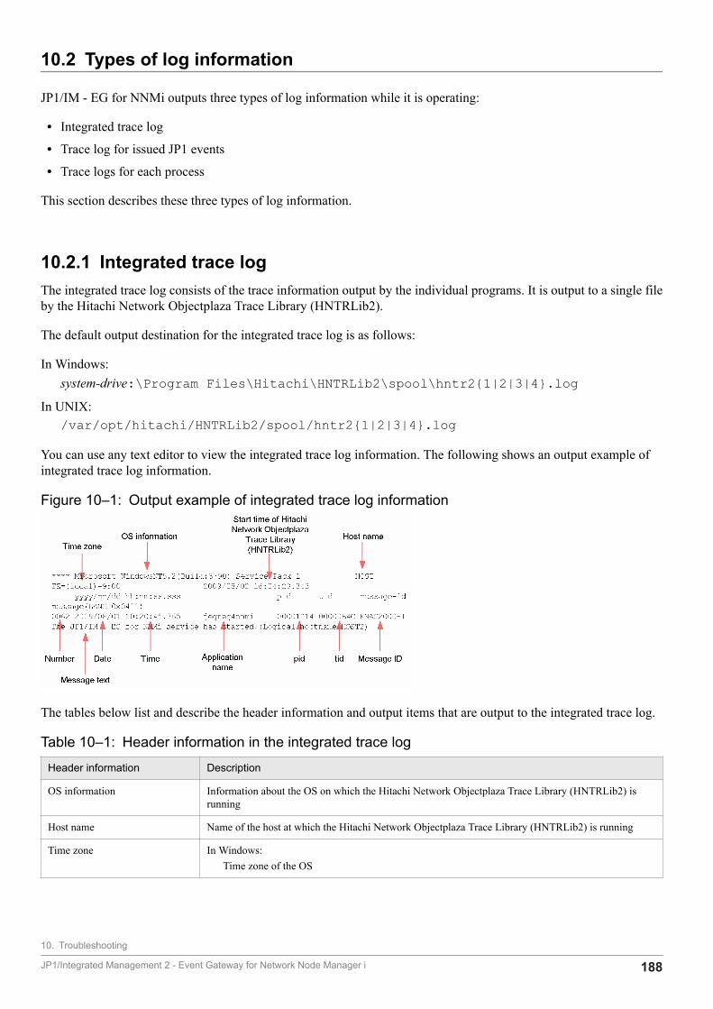
10.2 Types of log information
JP1/IM - EG for NNMi outputs three types of log information while it is operating:
• Integrated trace log
• Trace log for issued JP1 events
• Trace logs for each process
This section describes these three types of log information.
10.2.1 Integrated trace logThe integrated trace log consists of the trace information output by the individual programs. It is output to a single fileby the Hitachi Network Objectplaza Trace Library (HNTRLib2).
The default output destination for the integrated trace log is as follows:
In Windows:system-drive:\Program Files\Hitachi\HNTRLib2\spool\hntr2{1|2|3|4}.log
In UNIX:/var/opt/hitachi/HNTRLib2/spool/hntr2{1|2|3|4}.log
You can use any text editor to view the integrated trace log information. The following shows an output example ofintegrated trace log information.
Figure 10‒1: Output example of integrated trace log information
The tables below list and describe the header information and output items that are output to the integrated trace log.
Table 10‒1: Header information in the integrated trace log
Header information Description
OS information Information about the OS on which the Hitachi Network Objectplaza Trace Library (HNTRLib2) isrunning
Host name Name of the host at which the Hitachi Network Objectplaza Trace Library (HNTRLib2) is running
Time zone In Windows:Time zone of the OS
10. Troubleshooting
JP1/Integrated Management 2 - Event Gateway for Network Node Manager i 188
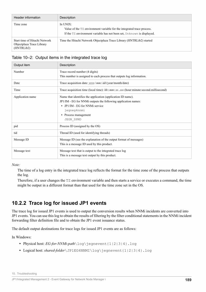
Header information Description
Time zone In UNIX:Value of the TZ environment variable for the integrated trace process.If the TZ environment variable has not been set, Unknown is displayed.
Start time of Hitachi NetworkObjectplaza Trace Library(HNTRLib2)
Time the Hitachi Network Objectplaza Trace Library (HNTRLib2) started
Table 10‒2: Output items in the integrated trace log
Output item Description
Number Trace record number (4 digits)This number is assigned to each process that outputs log information.
Date Trace acquisition date: yyyy/mm/dd (year/month/date)
Time Trace acquisition time (local time): hh:mm:ss.sss (hour:minute:second.millisecond)
Application name Name that identifies the application (application ID name).JP1/IM - EG for NNMi outputs the following application names:• JP1/IM - EG for NNMi servicejegneg4nnmi
• Process managementJEGN_SPMD
pid Process ID (assigned by the OS)
tid Thread ID (used for identifying threads)
Message ID Message ID (see the explanation of the output format of messages)This is a message ID used by this product.
Message text Message text that is output to the integrated trace logThis is a message text output by this product.
Note:The time of a log entry in the integrated trace log reflects the format for the time zone of the process that outputsthe log.Therefore, if a user changes the TZ environment variable and then starts a service or executes a command, the timemight be output in a different format than that used for the time zone set in the OS.
10.2.2 Trace log for issued JP1 eventsThe trace log for issued JP1 events is used to output the conversion results when NNMi incidents are converted intoJP1 events. You can use this log to obtain the results of filtering by the filter conditional statements in the NNMi incidentforwarding filter definition file and to obtain the JP1 event issuance status.
The default output destinations for trace logs for issued JP1 events are as follows:
In Windows:
• Physical host: EG-for-NNMi-path\log\jegnevent{1|2|3|4}.log• Logical host: shared-folder\JP1EG4NNMI\log\jegnevent{1|2|3|4}.log
10. Troubleshooting
JP1/Integrated Management 2 - Event Gateway for Network Node Manager i 189
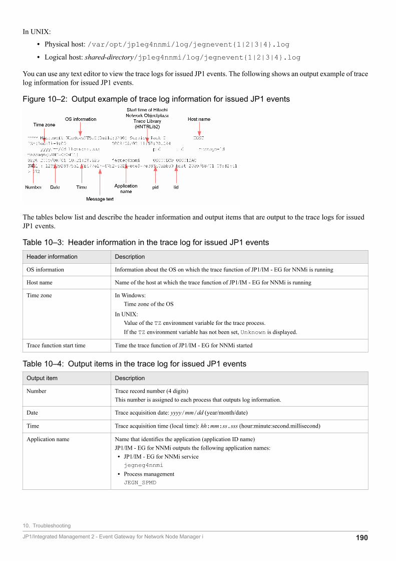
In UNIX:
• Physical host: /var/opt/jp1eg4nnmi/log/jegnevent{1|2|3|4}.log• Logical host: shared-directory/jp1eg4nnmi/log/jegnevent{1|2|3|4}.log
You can use any text editor to view the trace logs for issued JP1 events. The following shows an output example of tracelog information for issued JP1 events.
Figure 10‒2: Output example of trace log information for issued JP1 events
The tables below list and describe the header information and output items that are output to the trace logs for issuedJP1 events.
Table 10‒3: Header information in the trace log for issued JP1 events
Header information Description
OS information Information about the OS on which the trace function of JP1/IM - EG for NNMi is running
Host name Name of the host at which the trace function of JP1/IM - EG for NNMi is running
Time zone In Windows:Time zone of the OS
In UNIX:Value of the TZ environment variable for the trace process.If the TZ environment variable has not been set, Unknown is displayed.
Trace function start time Time the trace function of JP1/IM - EG for NNMi started
Table 10‒4: Output items in the trace log for issued JP1 events
Output item Description
Number Trace record number (4 digits)This number is assigned to each process that outputs log information.
Date Trace acquisition date: yyyy/mm/dd (year/month/date)
Time Trace acquisition time (local time): hh:mm:ss.sss (hour:minute:second.millisecond)
Application name Name that identifies the application (application ID name)JP1/IM - EG for NNMi outputs the following application names:• JP1/IM - EG for NNMi servicejegneg4nnmi
• Process managementJEGN_SPMD
10. Troubleshooting
JP1/Integrated Management 2 - Event Gateway for Network Node Manager i 190
Output item Description
pid Process ID (assigned by the OS)
tid Thread ID (used for identifying threads)
Message text Message text that is output to the trace log for issued JP1 eventsThis is a message text output by this product.
Format of message textThe following shows the format of the message texts that are output to the trace log for issued JP1 events:conversion-resultΔ:Δacquisition-request-date-and-timeΔUUIDΔsource-node-nameΔcreation-date-and-timeΔ>Δevent-database-numberΔ indicates one or more consecutive spaces or tabs.The following shows an output example of a message text.
Figure 10‒3: Output example of a message text in the trace log for issued JP1 events
The following table describes the items in the message text.
Table 10‒5: Items in the message text in the trace log for issued JP1 events
Item Description
Conversion result Result of converting an NNMi incident into a JP1 event:
FWDnIndicates that the NNMi incident was converted into a JP1 event because filter conditionalstatement n specified in the forwarding condition block were satisfied.
EXCIndicates that the NNMi incident was not converted into a JP1 event because none of thefilter conditional statements specified in the forwarding condition block was satisfied.
Acquisition request date and time Date and time an NNMi incident acquisition request was issued to NNMiThis value is expressed as the elapsed time in milliseconds since 1970-01-01 at 00:00:00(world standard time).
UUID UUID of the NNMi incident
Source node name Source node name of the NNMi incident
Creation date and time NNMi incident creation date and time (local time: yyyy/mm/dd hh:mm:ss (year/month/date hour:minute:second))
Event database number Serial number of the JP1 event that was issued by converting the NNMi incidentThis item is output only when the conversion result is FWDn.
Note:The time of a log entry in the trace log for issued JP1 events reflects the format for the time zone of the process thatoutputs the log.Therefore, if a user changes the TZ environment variable and then starts a service or executes a command, the timemight be output in a different format than that used for the time zone set in the OS.
10. Troubleshooting
JP1/Integrated Management 2 - Event Gateway for Network Node Manager i 191

10.2.3 Trace logs for each processThe trace logs for each process consist of log information that is output by each function of JP1/IM - EG for NNMi.The log information is output to a different log file for each function. Note that the contents of these trace logs are notdisclosed because they contain product information.
10. Troubleshooting
JP1/Integrated Management 2 - Event Gateway for Network Node Manager i 192
10.3 Data to be collected in the event of an error
This section describes the data that needs to be collected when an error has occurred.
JP1/IM - EG for NNMi provides the data collection tool (jegn_log command) that collects the needed data in thebatch mode. For details about the jegn_log command, see jegn_log.bat (Windows only) or jegn_log.sh (UNIX only)in 7. Commands.
The following describes the data that needs to be collected in Windows and UNIX.
10.3.1 Data to be collected (in Windows)This subsection describes the data to be collected in Windows when an error has occurred.
The data collection tool (jegn_log.bat command) classifies the target folders and files for data collection intoprimary data and secondary data categories and then stores the collected data directly under the specified data storagefolder.
The following tables show the organization of folders for the data that is stored directly under the data storage folderand their contents.
Table 10‒6: Organization and contents of data folders (physical host)
Folder name Type Data that is stored
data-storage-folder\jp1_default\eg4nnmi_1st\oslog Primary data OS log information
data-storage-folder\jp1_default\eg4nnmi_1st\spool Integrated trace log
data-storage-folder\jp1_default\eg4nnmi_1st\eg4nnmi Information about JP1/IM - EG forNNMi
data-storage-folder\jp1_default\eg4nnmi_1st\base Information about JP1/Base
data-storage-folder\jp1_default\eg4nnmi_1st\ucpsb Information about Web server
data-storage-folder\jp1_default\eg4nnmi_2nd\oslog Secondary data OS log information
data-storage-folder\jp1_default\eg4nnmi_2nd\base Information about JP1/Base
Table 10‒7: Organization and contents of data folders (logical host)
Folder name Type Data that is stored
data-storage-folder\logical-host-name\eg4nnmi_1st\oslog Primary data OS log information
data-storage-folder\logical-host-name\eg4nnmi_1st\eg4nnmi Information about JP1/IM - EG forNNMi
data-storage-folder\logical-host-name\eg4nnmi_1st\base Information about JP1/Base
data-storage-folder\logical-host-name\eg4nnmi_1st\ucpsb Information about Web server
data-storage-folder\logical-host-name\eg4nnmi_2nd\oslog Secondary data OS log information
data-storage-folder\logical-host-name\eg4nnmi_2nd\base Information about JP1/Base
For details about the jegn_log.bat command, see jegn_log.bat (Windows only) in 7. Commands.
10. Troubleshooting
JP1/Integrated Management 2 - Event Gateway for Network Node Manager i 193
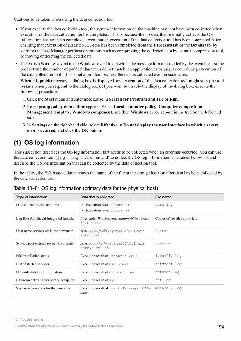
Cautions to be taken when using the data collection tool
• If you execute the data collection tool, the system information on the machine may not have been collected whenexecution of the data collection tool is completed. This is because the process that internally collects the OSinformation has not been completed, even though execution of the data collection tool has been completed.Afterensuring that execution of msinfo32.exe has been completed from the Processes tab or the Details tab, bystarting the Task Manager,perform operations such as compressing the collected data by using a compression tool,or moving or deleting the collected data.
• If there is a Windows event in the Windows event log in which the message format provided by the event log-issuingproduct and the number of padded characters do not match, an application error might occur during execution ofthe data collection tool. This is not a problem because the data is collected even in such cases.When this problem occurs, a dialog box is displayed, and execution of the data collection tool might stop (the toolrestarts when you respond to the dialog box). If you want to disable the display of the dialog box, execute thefollowing procedure:
1. Click the Start menu and enter gpedit.msc in Search for Program and File or Run.
2. Local group policy data editor appears. Select Local computer policy, Computer composition,Management template, Windows component, and then Windows error report in the tree on the left-handside.
3. In Settings on the right-hand side, select Effective in Do not display the user interface in which a severeerror occurred, and click the OK button.
(1) OS log informationThis subsection describes the OS log information that needs to be collected when an error has occurred. You can usethe data collection tool (jegn_log.bat command) to collect the OS log information. The tables below list anddescribe the OS log information that can be collected by the data collection tool.
In the tables, the File name column shows the name of the file at the storage location after data has been collected bythe data collection tool.
Table 10‒8: OS log information (primary data for the physical host)
Type of information Data that is collected File name
Data collection date and time • Execution result of date /t• Execution result of time /t
date.log
Log files for Hitachi Integrated Installer Files under Windows-installation-folder\Temp\HCDINST\
Copies of the files at the left
Host name settings set in the computer system-root-folder\system32\drivers\etc\hosts
hosts
Service port settings set in the computer system-root-folder\system32\drivers\etc\services
services
NIC installation status Execution result of ipconfig /all ipconfig.log
List of started services Execution result of net start netstart.log
Network statistical information Execution result of netstat -nao netstat.log
Environment variables for the computer Execution result of set set.log
System information for the computer Execution result of msinfo32 /report file-name
msinfo32.log
10. Troubleshooting
JP1/Integrated Management 2 - Event Gateway for Network Node Manager i 194
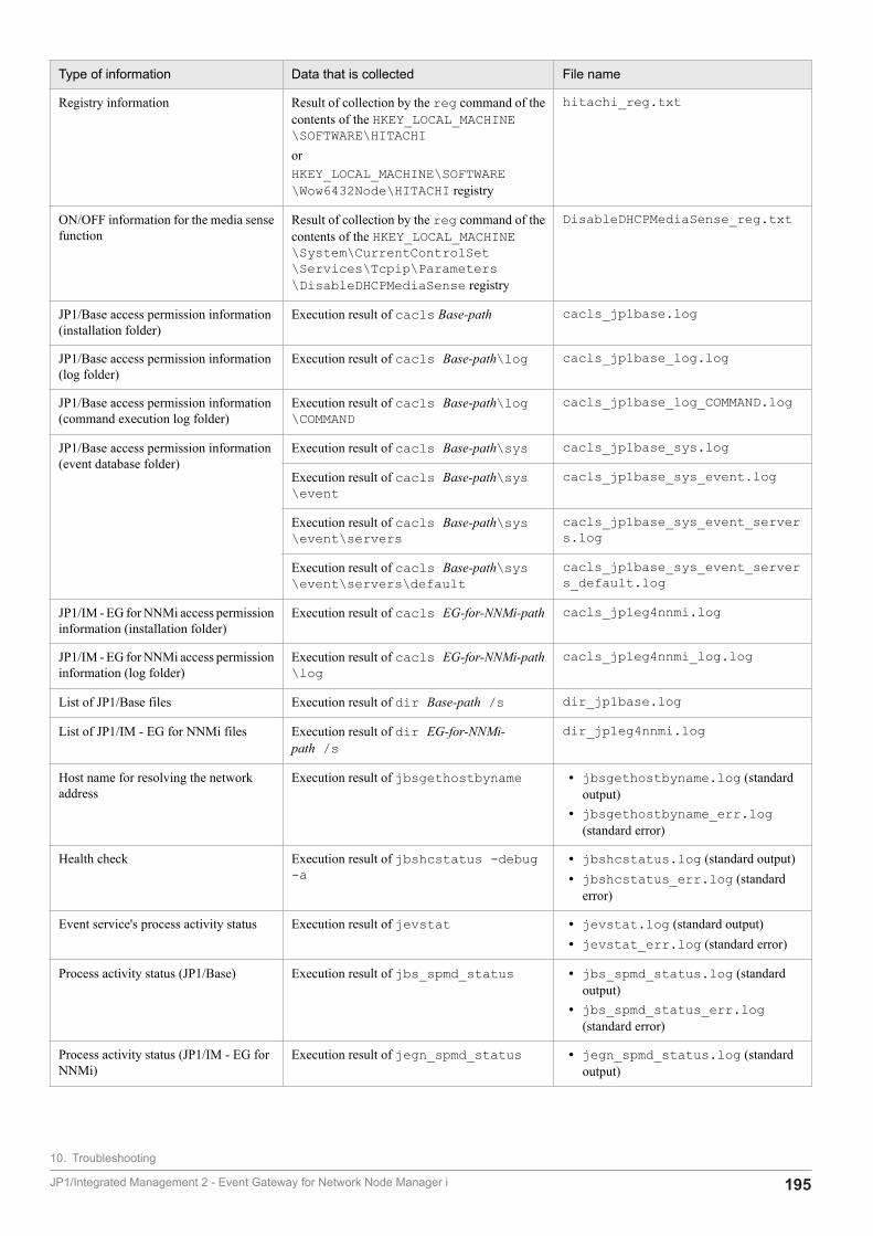
Type of information Data that is collected File name
Registry information Result of collection by the reg command of thecontents of the HKEY_LOCAL_MACHINE\SOFTWARE\HITACHIorHKEY_LOCAL_MACHINE\SOFTWARE\Wow6432Node\HITACHI registry
hitachi_reg.txt
ON/OFF information for the media sensefunction
Result of collection by the reg command of thecontents of the HKEY_LOCAL_MACHINE\System\CurrentControlSet\Services\Tcpip\Parameters\DisableDHCPMediaSense registry
DisableDHCPMediaSense_reg.txt
JP1/Base access permission information(installation folder)
Execution result of cacls Base-path cacls_jp1base.log
JP1/Base access permission information(log folder)
Execution result of cacls Base-path\log cacls_jp1base_log.log
JP1/Base access permission information(command execution log folder)
Execution result of cacls Base-path\log\COMMAND
cacls_jp1base_log_COMMAND.log
JP1/Base access permission information(event database folder)
Execution result of cacls Base-path\sys cacls_jp1base_sys.log
Execution result of cacls Base-path\sys\event
cacls_jp1base_sys_event.log
Execution result of cacls Base-path\sys\event\servers
cacls_jp1base_sys_event_servers.log
Execution result of cacls Base-path\sys\event\servers\default
cacls_jp1base_sys_event_servers_default.log
JP1/IM - EG for NNMi access permissioninformation (installation folder)
Execution result of cacls EG-for-NNMi-path cacls_jp1eg4nnmi.log
JP1/IM - EG for NNMi access permissioninformation (log folder)
Execution result of cacls EG-for-NNMi-path\log
cacls_jp1eg4nnmi_log.log
List of JP1/Base files Execution result of dir Base-path /s dir_jp1base.log
List of JP1/IM - EG for NNMi files Execution result of dir EG-for-NNMi-path /s
dir_jp1eg4nnmi.log
Host name for resolving the networkaddress
Execution result of jbsgethostbyname • jbsgethostbyname.log (standardoutput)
• jbsgethostbyname_err.log(standard error)
Health check Execution result of jbshcstatus -debug-a
• jbshcstatus.log (standard output)• jbshcstatus_err.log (standard
error)
Event service's process activity status Execution result of jevstat • jevstat.log (standard output)• jevstat_err.log (standard error)
Process activity status (JP1/Base) Execution result of jbs_spmd_status • jbs_spmd_status.log (standardoutput)
• jbs_spmd_status_err.log(standard error)
Process activity status (JP1/IM - EG forNNMi)
Execution result of jegn_spmd_status • jegn_spmd_status.log (standardoutput)
10. Troubleshooting
JP1/Integrated Management 2 - Event Gateway for Network Node Manager i 195
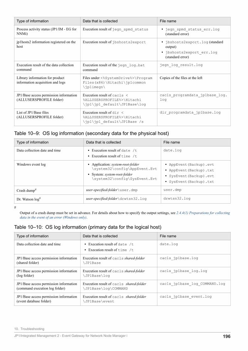
Type of information Data that is collected File name
Process activity status (JP1/IM - EG forNNMi)
Execution result of jegn_spmd_status • jegn_spmd_status_err.log(standard error)
jp1hosts2 information registered on thehost
Execution result of jbshosts2export • jbshosts2export.log (standardoutput)
• jbshosts2export_err.log(standard error)
Execution result of the data collectioncommand
Execution result of the jegn_log.batcommand
jegn_log_result.log
Library information for productinformation acquisition and logs
Files under <%SystemDrive%>\ProgramFiles(x86)\Hitachi\jp1common\jp1imegn\
Copies of the files at the left
JP1/Base access permission information(ALLUSERSPROFILE folder)
Execution result of cacls <%ALLUSERSPROFILE%>\Hitachi\jp1\jp1_default\JP1Base\log
cacls_programdata_jp1base_log.log
List of JP1/Base files(ALLUSERSPROFILE folder)
Execution result of dir <%ALLUSERSPROFILE%>\Hitachi\jp1\jp1_default\JP1Base /s
dir_programdata_jp1base.log
Table 10‒9: OS log information (secondary data for the physical host)
Type of information Data that is collected File name
Data collection date and time • Execution result of date /t• Execution result of time /t
date.log
Windows event log • Application: system-root-folder\system32\config\AppEvent.Evt
• System: system-root-folder\system32\config\SysEvent.Evt
• AppEvent(Backup).evt• AppEvent(Backup).txt• SysEvent(Backup).evt• SysEvent(Backup).txt
Crash dump# user-specified-folder\user.dmp user.dmp
Dr. Watson log# user-specified-folder\drwtsn32.log drwtsn32.log
#Output of a crash dump must be set in advance. For details about how to specify the output settings, see 2.4.4(1) Preparations for collectingdata in the event of an error (Windows only).
Table 10‒10: OS log information (primary data for the logical host)
Type of information Data that is collected File name
Data collection date and time • Execution result of date /t• Execution result of time /t
date.log
JP1/Base access permission information(shared folder)
Execution result of cacls shared-folder\JP1Base
cacls_jp1base.log
JP1/Base access permission information(log folder)
Execution result of cacls shared-folder\JP1Base\log
cacls_jp1base_log.log
JP1/Base access permission information(command execution log folder)
Execution result of cacls shared-folder\JP1Base\log\COMMAND
cacls_jp1base_log_COMMAND.log
JP1/Base access permission information(event database folder)
Execution result of cacls shared-folder\JP1Base\event
cacls_jp1base_event.log
10. Troubleshooting
JP1/Integrated Management 2 - Event Gateway for Network Node Manager i 196
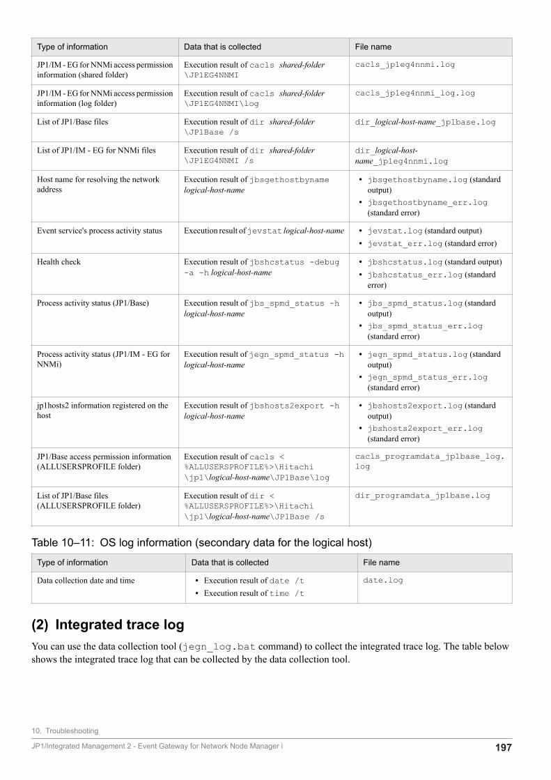
Type of information Data that is collected File name
JP1/IM - EG for NNMi access permissioninformation (shared folder)
Execution result of cacls shared-folder\JP1EG4NNMI
cacls_jp1eg4nnmi.log
JP1/IM - EG for NNMi access permissioninformation (log folder)
Execution result of cacls shared-folder\JP1EG4NNMI\log
cacls_jp1eg4nnmi_log.log
List of JP1/Base files Execution result of dir shared-folder\JP1Base /s
dir_logical-host-name_jp1base.log
List of JP1/IM - EG for NNMi files Execution result of dir shared-folder\JP1EG4NNMI /s
dir_logical-host-name_jp1eg4nnmi.log
Host name for resolving the networkaddress
Execution result of jbsgethostbynamelogical-host-name
• jbsgethostbyname.log (standardoutput)
• jbsgethostbyname_err.log(standard error)
Event service's process activity status Execution result of jevstat logical-host-name • jevstat.log (standard output)• jevstat_err.log (standard error)
Health check Execution result of jbshcstatus -debug-a -h logical-host-name
• jbshcstatus.log (standard output)• jbshcstatus_err.log (standard
error)
Process activity status (JP1/Base) Execution result of jbs_spmd_status -hlogical-host-name
• jbs_spmd_status.log (standardoutput)
• jbs_spmd_status_err.log(standard error)
Process activity status (JP1/IM - EG forNNMi)
Execution result of jegn_spmd_status -hlogical-host-name
• jegn_spmd_status.log (standardoutput)
• jegn_spmd_status_err.log(standard error)
jp1hosts2 information registered on thehost
Execution result of jbshosts2export -hlogical-host-name
• jbshosts2export.log (standardoutput)
• jbshosts2export_err.log(standard error)
JP1/Base access permission information(ALLUSERSPROFILE folder)
Execution result of cacls <%ALLUSERSPROFILE%>\Hitachi\jp1\logical-host-name\JP1Base\log
cacls_programdata_jp1base_log.log
List of JP1/Base files(ALLUSERSPROFILE folder)
Execution result of dir <%ALLUSERSPROFILE%>\Hitachi\jp1\logical-host-name\JP1Base /s
dir_programdata_jp1base.log
Table 10‒11: OS log information (secondary data for the logical host)
Type of information Data that is collected File name
Data collection date and time • Execution result of date /t• Execution result of time /t
date.log
(2) Integrated trace logYou can use the data collection tool (jegn_log.bat command) to collect the integrated trace log. The table belowshows the integrated trace log that can be collected by the data collection tool.
10. Troubleshooting
JP1/Integrated Management 2 - Event Gateway for Network Node Manager i 197
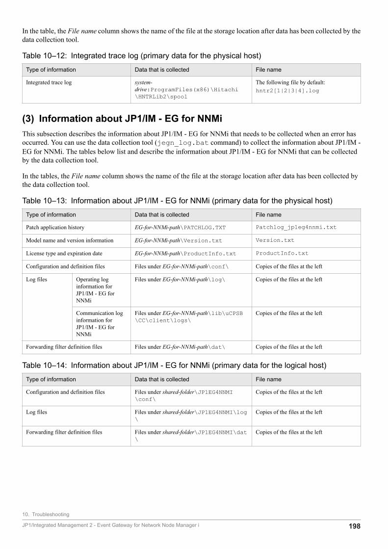
In the table, the File name column shows the name of the file at the storage location after data has been collected by thedata collection tool.
Table 10‒12: Integrated trace log (primary data for the physical host)
Type of information Data that is collected File name
Integrated trace log system-drive:ProgramFiles(x86)\Hitachi\HNTRLib2\spool
The following file by default:hntr2[1|2|3|4].log
(3) Information about JP1/IM - EG for NNMiThis subsection describes the information about JP1/IM - EG for NNMi that needs to be collected when an error hasoccurred. You can use the data collection tool (jegn_log.bat command) to collect the information about JP1/IM -EG for NNMi. The tables below list and describe the information about JP1/IM - EG for NNMi that can be collectedby the data collection tool.
In the tables, the File name column shows the name of the file at the storage location after data has been collected bythe data collection tool.
Table 10‒13: Information about JP1/IM - EG for NNMi (primary data for the physical host)
Type of information Data that is collected File name
Patch application history EG-for-NNMi-path\PATCHLOG.TXT Patchlog_jp1eg4nnmi.txt
Model name and version information EG-for-NNMi-path\Version.txt Version.txt
License type and expiration date EG-for-NNMi-path\ProductInfo.txt ProductInfo.txt
Configuration and definition files Files under EG-for-NNMi-path\conf\ Copies of the files at the left
Log files Operating loginformation forJP1/IM - EG forNNMi
Files under EG-for-NNMi-path\log\ Copies of the files at the left
Communication loginformation forJP1/IM - EG forNNMi
Files under EG-for-NNMi-path\lib\uCPSB\CC\client\logs\
Copies of the files at the left
Forwarding filter definition files Files under EG-for-NNMi-path\dat\ Copies of the files at the left
Table 10‒14: Information about JP1/IM - EG for NNMi (primary data for the logical host)
Type of information Data that is collected File name
Configuration and definition files Files under shared-folder\JP1EG4NNMI\conf\
Copies of the files at the left
Log files Files under shared-folder\JP1EG4NNMI\log\
Copies of the files at the left
Forwarding filter definition files Files under shared-folder\JP1EG4NNMI\dat\
Copies of the files at the left
10. Troubleshooting
JP1/Integrated Management 2 - Event Gateway for Network Node Manager i 198
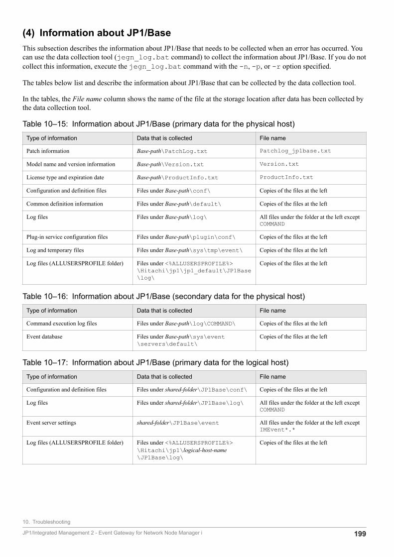
(4) Information about JP1/BaseThis subsection describes the information about JP1/Base that needs to be collected when an error has occurred. Youcan use the data collection tool (jegn_log.bat command) to collect the information about JP1/Base. If you do notcollect this information, execute the jegn_log.bat command with the -n, -p, or -r option specified.
The tables below list and describe the information about JP1/Base that can be collected by the data collection tool.
In the tables, the File name column shows the name of the file at the storage location after data has been collected bythe data collection tool.
Table 10‒15: Information about JP1/Base (primary data for the physical host)
Type of information Data that is collected File name
Patch information Base-path\PatchLog.txt Patchlog_jp1base.txt
Model name and version information Base-path\Version.txt Version.txt
License type and expiration date Base-path\ProductInfo.txt ProductInfo.txt
Configuration and definition files Files under Base-path\conf\ Copies of the files at the left
Common definition information Files under Base-path\default\ Copies of the files at the left
Log files Files under Base-path\log\ All files under the folder at the left exceptCOMMAND
Plug-in service configuration files Files under Base-path\plugin\conf\ Copies of the files at the left
Log and temporary files Files under Base-path\sys\tmp\event\ Copies of the files at the left
Log files (ALLUSERSPROFILE folder) Files under <%ALLUSERSPROFILE%>\Hitachi\jp1\jp1_default\JP1Base\log\
Copies of the files at the left
Table 10‒16: Information about JP1/Base (secondary data for the physical host)
Type of information Data that is collected File name
Command execution log files Files under Base-path\log\COMMAND\ Copies of the files at the left
Event database Files under Base-path\sys\event\servers\default\
Copies of the files at the left
Table 10‒17: Information about JP1/Base (primary data for the logical host)
Type of information Data that is collected File name
Configuration and definition files Files under shared-folder\JP1Base\conf\ Copies of the files at the left
Log files Files under shared-folder\JP1Base\log\ All files under the folder at the left exceptCOMMAND
Event server settings shared-folder\JP1Base\event All files under the folder at the left exceptIMEvent*.*
Log files (ALLUSERSPROFILE folder) Files under <%ALLUSERSPROFILE%>\Hitachi\jp1\logical-host-name\JP1Base\log\
Copies of the files at the left
10. Troubleshooting
JP1/Integrated Management 2 - Event Gateway for Network Node Manager i 199
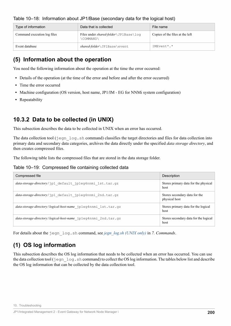
Table 10‒18: Information about JP1/Base (secondary data for the logical host)
Type of information Data that is collected File name
Command execution log files Files under shared-folder\JP1Base\log\COMMAND\
Copies of the files at the left
Event database shared-folder\JP1Base\event IMEvent*.*
(5) Information about the operationYou need the following information about the operation at the time the error occurred:
• Details of the operation (at the time of the error and before and after the error occurred)
• Time the error occurred
• Machine configuration (OS version, host name, JP1/IM - EG for NNMi system configuration)
• Repeatability
10.3.2 Data to be collected (in UNIX)This subsection describes the data to be collected in UNIX when an error has occurred.
The data collection tool (jegn_log.sh command) classifies the target directories and files for data collection intoprimary data and secondary data categories, archives the data directly under the specified data storage directory, andthen creates compressed files.
The following table lists the compressed files that are stored in the data storage folder.
Table 10‒19: Compressed file containing collected data
Compressed file Description
data-storage-directory/jp1_default_jp1eg4nnmi_1st.tar.gz Stores primary data for the physicalhost
data-storage-directory/jp1_default_jp1eg4nnmi_2nd.tar.gz Stores secondary data for thephysical host
data-storage-directory/logical-host-name_jp1eg4nnmi_1st.tar.gz Stores primary data for the logicalhost
data-storage-directory/logical-host-name_jp1eg4nnmi_2nd.tar.gz Stores secondary data for the logicalhost
For details about the jegn_log.sh command, see jegn_log.sh (UNIX only) in 7. Commands.
(1) OS log informationThis subsection describes the OS log information that needs to be collected when an error has occurred. You can usethe data collection tool (jegn_log.sh command) to collect the OS log information. The tables below list and describethe OS log information that can be collected by the data collection tool.
10. Troubleshooting
JP1/Integrated Management 2 - Event Gateway for Network Node Manager i 200

Table 10‒20: OS log information (primary data for the physical host)
Type of information Data that is collected Storage location#
Information about the installed Hitachiproducts
/etc/.hitachi/pplistd/pplistd ./var/opt/jp1eg4nnmi/log/_jp1_default/oslog/pplistd
Hitachi PP Installer installation log file /etc/.hitachi/.install.log* ./var/opt/jp1eg4nnmi/log/_jp1_default/oslog/.install.log*
Uninstallation log file for Hitachi PPInstaller
/etc/.hitachi/.uninstall.log* ./var/opt/jp1eg4nnmi/log/_jp1_default/oslog/.uninstall.log*
Common definition information Files under /opt/jp1/hcclibcnf/ ./opt/jp1/hcclibcnf/ (containscopies of the files indicated at left)
JP1/Base installation log files /tmp/HITACHI_JP1_INST_LOG/jp1base_inst{1|2|3|4|5}.log
./var/opt/jp1eg4nnmi/log/_jp1_default/oslog/HITACHI_JP1_INST_LOG/jp1base_inst{1|2|3|4|5}.log
JP1/IM - EG for NNMi installation logfiles
/tmp/HITACHI_JP1_INST_LOG/jp1eg_inst{1|2|3|4|5}.log
./var/opt/jp1eg4nnmi/log/_jp1_default/oslog/HITACHI_JP1_INST_LOG/jp1eg_inst{1|2|3|4|5}.log
JP1/IM - Manager installation log files /tmp/HITACHI_JP1_INST_LOG/jp1imm_inst{1|2|3|4|5}.log
./var/opt/jp1eg4nnmi/log/_jp1_default/oslog/HITACHI_JP1_INST_LOG/jp1imm_inst{1|2|3|4|5}.log
List of files • Execution result of ls -lRa /opt/jp1eg4nnmi
• Execution result of ls -lRa /etc/opt/jp1eg4nnmi
• Execution result of ls -lRa /var/opt/jp1eg4nnmi
• Execution result of ls -lRa /opt/jp1base
• Execution result of ls -lRa /etc/opt/jp1base
• Execution result of ls -lRa /var/opt/jp1base
• Execution result of ls -lRa /tmp/HITACHI_JP1_INST_LOG
• Execution result of ls -lRa /etc/.hitachi
• Execution result of ls -lRa /etc/.hlic
./var/opt/jp1eg4nnmi/log/_jp1_default/oslog/inst_dir_lRa.log
• Execution result of ls -lRLa /opt/jp1eg4nnmi
• Execution result of ls -lRLa /etc/opt/jp1eg4nnmi
• Execution result of ls -lRLa /var/opt/jp1eg4nnmi
• Execution result of ls -lRLa /opt/jp1base
• Execution result of ls -lRLa /etc/opt/jp1base
./var/opt/jp1eg4nnmi/log/_jp1_default/oslog/inst_dir.log
10. Troubleshooting
JP1/Integrated Management 2 - Event Gateway for Network Node Manager i 201
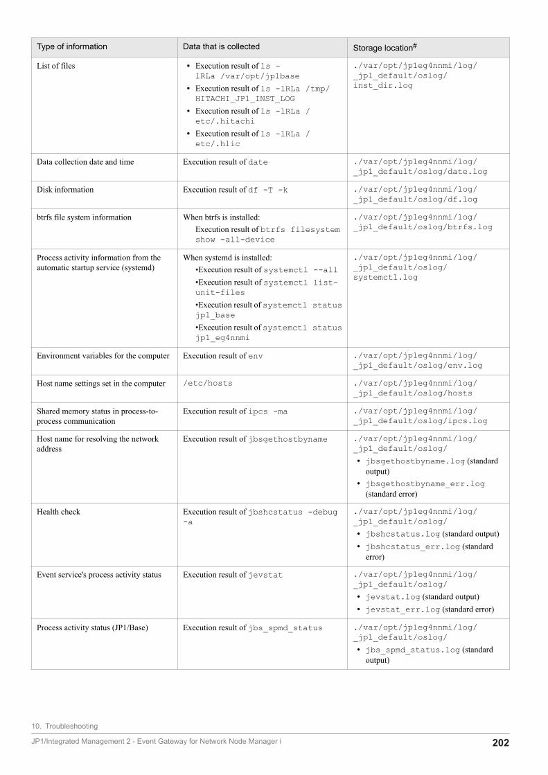
Type of information Data that is collected Storage location#
List of files • Execution result of ls -lRLa /var/opt/jp1base
• Execution result of ls -lRLa /tmp/HITACHI_JP1_INST_LOG
• Execution result of ls -lRLa /etc/.hitachi
• Execution result of ls -lRLa /etc/.hlic
./var/opt/jp1eg4nnmi/log/_jp1_default/oslog/inst_dir.log
Data collection date and time Execution result of date ./var/opt/jp1eg4nnmi/log/_jp1_default/oslog/date.log
Disk information Execution result of df -T -k ./var/opt/jp1eg4nnmi/log/_jp1_default/oslog/df.log
btrfs file system information When btrfs is installed:Execution result of btrfs filesystemshow -all-device
./var/opt/jp1eg4nnmi/log/_jp1_default/oslog/btrfs.log
Process activity information from theautomatic startup service (systemd)
When systemd is installed:•Execution result of systemctl --all•Execution result of systemctl list-unit-files•Execution result of systemctl statusjp1_base•Execution result of systemctl statusjp1_eg4nnmi
./var/opt/jp1eg4nnmi/log/_jp1_default/oslog/systemctl.log
Environment variables for the computer Execution result of env ./var/opt/jp1eg4nnmi/log/_jp1_default/oslog/env.log
Host name settings set in the computer /etc/hosts ./var/opt/jp1eg4nnmi/log/_jp1_default/oslog/hosts
Shared memory status in process-to-process communication
Execution result of ipcs -ma ./var/opt/jp1eg4nnmi/log/_jp1_default/oslog/ipcs.log
Host name for resolving the networkaddress
Execution result of jbsgethostbyname ./var/opt/jp1eg4nnmi/log/_jp1_default/oslog/• jbsgethostbyname.log (standard
output)• jbsgethostbyname_err.log
(standard error)
Health check Execution result of jbshcstatus -debug-a
./var/opt/jp1eg4nnmi/log/_jp1_default/oslog/• jbshcstatus.log (standard output)• jbshcstatus_err.log (standard
error)
Event service's process activity status Execution result of jevstat ./var/opt/jp1eg4nnmi/log/_jp1_default/oslog/• jevstat.log (standard output)• jevstat_err.log (standard error)
Process activity status (JP1/Base) Execution result of jbs_spmd_status ./var/opt/jp1eg4nnmi/log/_jp1_default/oslog/• jbs_spmd_status.log (standard
output)
10. Troubleshooting
JP1/Integrated Management 2 - Event Gateway for Network Node Manager i 202
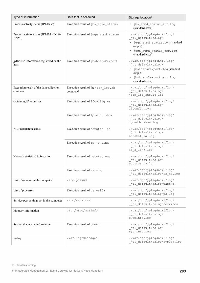
Type of information Data that is collected Storage location#
Process activity status (JP1/Base) Execution result of jbs_spmd_status • jbs_spmd_status_err.log(standard error)
Process activity status (JP1/IM - EG forNNMi)
Execution result of jegn_spmd_status ./var/opt/jp1eg4nnmi/log/_jp1_default/oslog/• jegn_spmd_status.log (standard
output)• jegn_spmd_status_err.log
(standard error)
jp1hosts2 information registered on thehost
Execution result of jbshosts2export ./var/opt/jp1eg4nnmi/log/_jp1_default/oslog/• jbshosts2export.log (standard
output)• jbshosts2export_err.log
(standard error)
Execution result of the data collectioncommand
Execution result of the jegn_log.shcommand
./var/opt/jp1eg4nnmi/log/_jp1_default/oslog/jegn_log_result.log
Obtaining IP addresses Execution result of ifconfig -a ./var/opt/jp1eg4nnmi/log/_jp1_default/oslog/ifconfig.log
Execution result of ip addr show ./var/opt/jp1eg4nnmi/log/_jp1_default/oslog/ip_addr_show.log
NIC installation status Execution result of netstat -ia ./var/opt/jp1eg4nnmi/log/_jp1_default/oslog/netstat_ia.log
Execution result of ip -s link ./var/opt/jp1eg4nnmi/log/_jp1_default/oslog/ip_s_link.log
Network statistical information Execution result of netstat -nap ./var/opt/jp1eg4nnmi/log/_jp1_default/oslog/netstat_na.log
Execution result of ss -nap ./var/opt/jp1eg4nnmi/log/_jp1_default/oslog/ss_na.log
List of users set in the computer /etc/passwd ./var/opt/jp1eg4nnmi/log/_jp1_default/oslog/passwd
List of processes Execution result of ps -elfa ./var/opt/jp1eg4nnmi/log/_jp1_default/oslog/ps.log
Service port settings set in the computer /etc/services ./var/opt/jp1eg4nnmi/log/_jp1_default/oslog/services
Memory information cat /proc/meminfo ./var/opt/jp1eg4nnmi/log/_jp1_default/oslog/swapinfo.log
System diagnostic information Execution result of dmesg ./var/opt/jp1eg4nnmi/log/_jp1_default/oslog/sys_info.log
syslog /var/log/messages ./var/opt/jp1eg4nnmi/log/_jp1_default/oslog/syslog.log
10. Troubleshooting
JP1/Integrated Management 2 - Event Gateway for Network Node Manager i 203
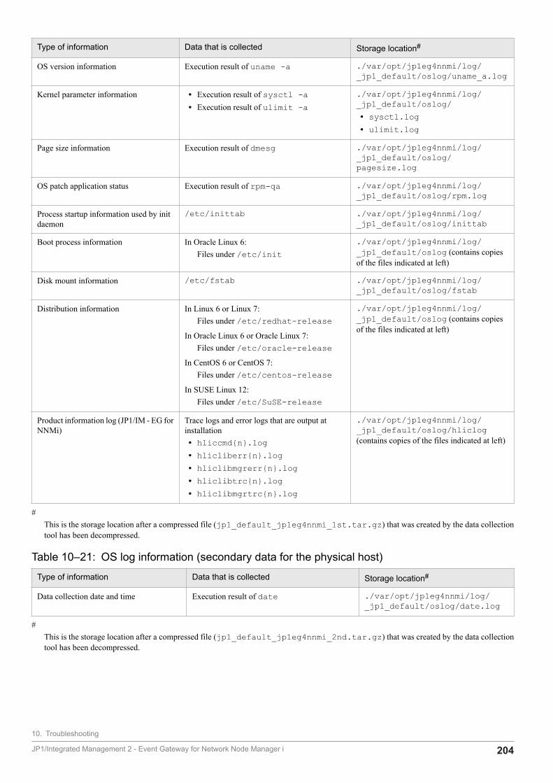
Type of information Data that is collected Storage location#
OS version information Execution result of uname -a ./var/opt/jp1eg4nnmi/log/_jp1_default/oslog/uname_a.log
Kernel parameter information • Execution result of sysctl -a• Execution result of ulimit -a
./var/opt/jp1eg4nnmi/log/_jp1_default/oslog/• sysctl.log• ulimit.log
Page size information Execution result of dmesg ./var/opt/jp1eg4nnmi/log/_jp1_default/oslog/pagesize.log
OS patch application status Execution result of rpm-qa ./var/opt/jp1eg4nnmi/log/_jp1_default/oslog/rpm.log
Process startup information used by initdaemon
/etc/inittab ./var/opt/jp1eg4nnmi/log/_jp1_default/oslog/inittab
Boot process information In Oracle Linux 6:Files under /etc/init
./var/opt/jp1eg4nnmi/log/_jp1_default/oslog (contains copiesof the files indicated at left)
Disk mount information /etc/fstab ./var/opt/jp1eg4nnmi/log/_jp1_default/oslog/fstab
Distribution information In Linux 6 or Linux 7:Files under /etc/redhat-release
In Oracle Linux 6 or Oracle Linux 7:Files under /etc/oracle-release
In CentOS 6 or CentOS 7:Files under /etc/centos-release
In SUSE Linux 12:Files under /etc/SuSE-release
./var/opt/jp1eg4nnmi/log/_jp1_default/oslog (contains copiesof the files indicated at left)
Product information log (JP1/IM - EG forNNMi)
Trace logs and error logs that are output atinstallation• hliccmd{n}.log• hlicliberr{n}.log• hliclibmgrerr{n}.log• hliclibtrc{n}.log• hliclibmgrtrc{n}.log
./var/opt/jp1eg4nnmi/log/_jp1_default/oslog/hliclog(contains copies of the files indicated at left)
#This is the storage location after a compressed file (jp1_default_jp1eg4nnmi_1st.tar.gz) that was created by the data collectiontool has been decompressed.
Table 10‒21: OS log information (secondary data for the physical host)
Type of information Data that is collected Storage location#
Data collection date and time Execution result of date ./var/opt/jp1eg4nnmi/log/_jp1_default/oslog/date.log
#This is the storage location after a compressed file (jp1_default_jp1eg4nnmi_2nd.tar.gz) that was created by the data collectiontool has been decompressed.
10. Troubleshooting
JP1/Integrated Management 2 - Event Gateway for Network Node Manager i 204
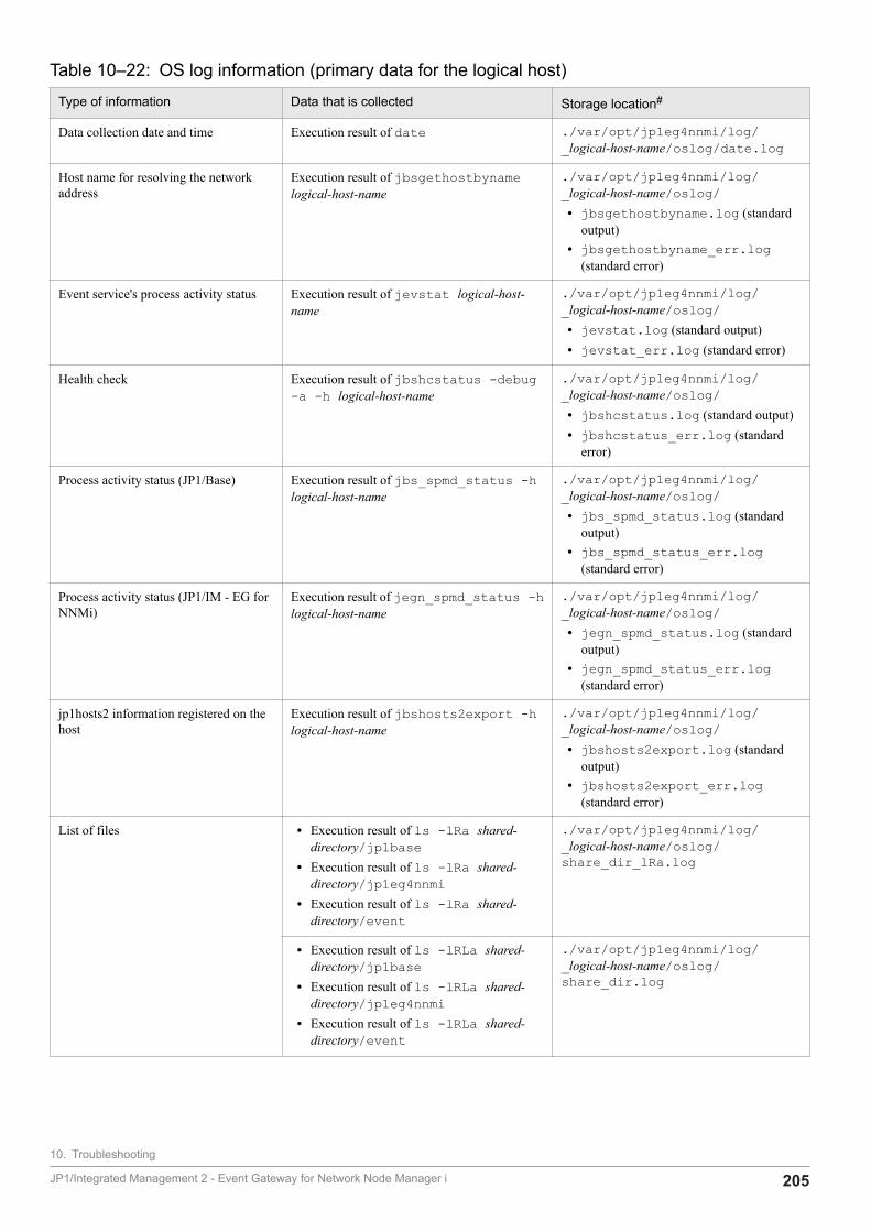
Table 10‒22: OS log information (primary data for the logical host)
Type of information Data that is collected Storage location#
Data collection date and time Execution result of date ./var/opt/jp1eg4nnmi/log/_logical-host-name/oslog/date.log
Host name for resolving the networkaddress
Execution result of jbsgethostbynamelogical-host-name
./var/opt/jp1eg4nnmi/log/_logical-host-name/oslog/• jbsgethostbyname.log (standard
output)• jbsgethostbyname_err.log
(standard error)
Event service's process activity status Execution result of jevstat logical-host-name
./var/opt/jp1eg4nnmi/log/_logical-host-name/oslog/• jevstat.log (standard output)• jevstat_err.log (standard error)
Health check Execution result of jbshcstatus -debug-a -h logical-host-name
./var/opt/jp1eg4nnmi/log/_logical-host-name/oslog/• jbshcstatus.log (standard output)• jbshcstatus_err.log (standard
error)
Process activity status (JP1/Base) Execution result of jbs_spmd_status -hlogical-host-name
./var/opt/jp1eg4nnmi/log/_logical-host-name/oslog/• jbs_spmd_status.log (standard
output)• jbs_spmd_status_err.log
(standard error)
Process activity status (JP1/IM - EG forNNMi)
Execution result of jegn_spmd_status -hlogical-host-name
./var/opt/jp1eg4nnmi/log/_logical-host-name/oslog/• jegn_spmd_status.log (standard
output)• jegn_spmd_status_err.log
(standard error)
jp1hosts2 information registered on thehost
Execution result of jbshosts2export -hlogical-host-name
./var/opt/jp1eg4nnmi/log/_logical-host-name/oslog/• jbshosts2export.log (standard
output)• jbshosts2export_err.log
(standard error)
List of files • Execution result of ls -lRa shared-directory/jp1base
• Execution result of ls -lRa shared-directory/jp1eg4nnmi
• Execution result of ls -lRa shared-directory/event
./var/opt/jp1eg4nnmi/log/_logical-host-name/oslog/share_dir_lRa.log
• Execution result of ls -lRLa shared-directory/jp1base
• Execution result of ls -lRLa shared-directory/jp1eg4nnmi
• Execution result of ls -lRLa shared-directory/event
./var/opt/jp1eg4nnmi/log/_logical-host-name/oslog/share_dir.log
10. Troubleshooting
JP1/Integrated Management 2 - Event Gateway for Network Node Manager i 205
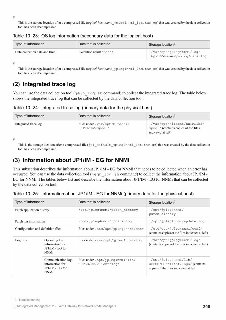
#This is the storage location after a compressed file (logical-host-name_jp1eg4nnmi_1st.tar.gz) that was created by the data collectiontool has been decompressed.
Table 10‒23: OS log information (secondary data for the logical host)
Type of information Data that is collected Storage location#
Data collection date and time Execution result of date ./var/opt/jp1eg4nnmi/log/_logical-host-name/oslog/date.log
#This is the storage location after a compressed file (logical-host-name_jp1eg4nnmi_2nd.tar.gz) that was created by the data collectiontool has been decompressed.
(2) Integrated trace logYou can use the data collection tool (jegn_log.sh command) to collect the integrated trace log. The table belowshows the integrated trace log that can be collected by the data collection tool.
Table 10‒24: Integrated trace log (primary data for the physical host)
Type of information Data that is collected Storage location#
Integrated trace log Files under /var/opt/hitachi/HNTRLib2/spool/
./var/opt/hitachi/HNTRLib2/spool/ (contains copies of the filesindicated at left)
#This is the storage location after a compressed file (jp1_default_jp1eg4nnmi_1st.tar.gz) that was created by the data collectiontool has been decompressed.
(3) Information about JP1/IM - EG for NNMiThis subsection describes the information about JP1/IM - EG for NNMi that needs to be collected when an error hasoccurred. You can use the data collection tool (jegn_log.sh command) to collect the information about JP1/IM -EG for NNMi. The tables below list and describe the information about JP1/IM - EG for NNMi that can be collectedby the data collection tool.
Table 10‒25: Information about JP1/IM - EG for NNMi (primary data for the physical host)
Type of information Data that is collected Storage location#
Patch application history /opt/jp1eg4nnmi/patch_history ./opt/jp1eg4nnmi/patch_history
Patch log information /opt/jp1eg4nnmi/update.log ./opt/jp1eg4nnmi/update.log
Configuration and definition files Files under /etc/opt/jp1eg4nnmi/conf ./etc/opt/jp1eg4nnmi/conf/(contains copies of the files indicated at left)
Log files Operating loginformation forJP1/IM - EG forNNMi
Files under /var/opt/jp1eg4nnmi/log ./var/opt/jp1eg4nnmi/log/(contains copies of the files indicated at left)
Communication loginformation forJP1/IM - EG forNNMi
Files under /opt/jp1eg4nnmi/lib/uCPSB/CC/client/logs
./opt/jp1eg4nnmi/lib/uCPSB/CC/client/logs/ (containscopies of the files indicated at left)
10. Troubleshooting
JP1/Integrated Management 2 - Event Gateway for Network Node Manager i 206
Type of information Data that is collected Storage location#
Core analysis information (result ofanalysis by seraph)
Analysis result of the core fileunder /var/opt/jp1eg4nnmi/log
./var/opt/jp1eg4nnmi/log/_jp1_default/oslog/core_module-name.log
Forwarding filter definition files Files under /var/opt/jp1eg4nnmi/dat ./var/opt/jp1eg4nnmi/dat/(contains copies of the files indicated at left)
Automated startup and stop scripts Files under /etc/opt/jp1eg4nnmi ./etc/opt/jp1eg4nnmi/ (containscopies of the files indicated at left)
#This is the storage location after a compressed file (jp1_default_jp1eg4nnmi_1st.tar.gz) that was created by the data collectiontool has been decompressed.
Table 10‒26: Information about JP1/IM - EG for NNMi (secondary data for the physical host)
Type of information Data that is collected Storage location#
Core analysis information (result of the carcommand)
car file of the core file under /var/opt/jp1eg4nnmi/log
./var/opt/jp1eg4nnmi/log/_jp1_default/core/core_module-name_car.tar.gz
#This is the storage location after a compressed file (jp1_default_jp1eg4nnmi_2nd.tar.gz) that was created by the data collectiontool has been decompressed.
Table 10‒27: Information about JP1/IM - EG for NNMi (primary data for the logical host)
Type of information Data that is collected Storage location#
Configuration and definition files Files under shared-directory/jp1eg4nnmi/conf
.shared-directory/jp1eg4nnmi/conf/ (contains copies of the filesindicated at left)
Log files Files under shared-directory/jp1eg4nnmi/log
.shared-directory/jp1eg4nnmi/log/(contains copies of the files indicated at left)
Core analysis information (result ofanalysis by seraph)
Analysis result of the core file under shared-directory/jp1eg4nnmi/log
./var/opt/jp1eg4nnmi/log/_shared-directory/oslog/core_module-name.log
Forwarding filter definition files Files under shared-directory/jp1eg4nnmi/dat
.shared-directory/jp1eg4nnmi/dat/(contains copies of the files indicated at left)
#This is the storage location after a compressed file (logical-host-name_jp1eg4nnmi_1st.tar.gz) that was created by the data collectiontool has been decompressed.
Table 10‒28: Information about JP1/IM - EG for NNMi (secondary data for the logical host)
Type of information Data that is collected Storage location#
Core analysis information (result of the carcommand)
car file of the core file under shared-directory/jp1eg4nnmi/log
./var/opt/jp1eg4nnmi/log/_shared-directory/core/core_module-name_car.tar.gz
#This is the storage location after a compressed file (logical-host-name_jp1eg4nnmi_2nd.tar.gz) that was created by the data collectiontool has been decompressed.
10. Troubleshooting
JP1/Integrated Management 2 - Event Gateway for Network Node Manager i 207
(4) Information about JP1/BaseThis subsection describes the information about JP1/Base that needs to be collected when an error has occurred. Youcan use the data collection tool (jegn_log.sh command) to collect the information about JP1/Base. If you do notcollect this information, execute the jegn_log.sh command with the -n, -p, or -r option specified.
The tables below list and describe the information about JP1/Base that can be collected by the data collection tool.
Table 10‒29: Information about JP1/Base (primary data for the physical host)
Type of information Data that is collected Storage location#
Automated startup and stop scripts Files under /etc/opt/jp1base/ ./etc/opt/jp1base/ (containscopies of the files indicated at left)
Configuration and definition files Files under /etc/opt/jp1base/conf/ ./etc/opt/jp1base/conf/(contains copies of the files indicated at left)
Common definition information Files under /etc/opt/jp1base/default/
./etc/opt/jp1base/default/(contains copies of the files indicated at left)
Plug-in service configuration files Files under /opt/jp1base/plugin/conf/
./opt/jp1base/plugin/conf/(contains copies of the files indicated at left)
Patch application history /opt/jp1base/PatchInfo ./opt/jp1base/PatchInfo
Patch log information /opt/jp1base/PatchLog ./opt/jp1base/PatchLog
Log files /var/opt/jp1base/log ./var/opt/jp1base/log/ (containscopies of the files indicated at left except theCOMMAND and core files)
Log and temporary files Files under /var/opt/jp1base/sys/tmp/
./var/opt/jp1base/sys/tmp/(contains copies of the files indicated at left)
#This is the storage location after a compressed file (jp1_default_jp1eg4nnmi_1st.tar.gz) that was created by the data collectiontool has been decompressed.
Table 10‒30: Information about JP1/Base (secondary data for the physical host)
Type of information Data that is collected Storage location#
SES configuration files • /tmp/.JP1_SES*• /usr/tmp/jp1_ses• /usr/lib/jp1_ses/log• /usr/lib/jp1_ses/sys• /usr/bin/jp1_ses/jp*• /var/opt/jp1_ses
• ./tmp/.JP1_SES*• ./usr/tmp/jp1_ses• ./usr/lib/jp1_ses/log• ./usr/lib/jp1_ses/sys• ./usr/bin/jp1_ses/jp*• ./var/opt/jp1_ses
Command execution log files Files under /var/opt/jp1base/log/COMMAND/
./var/opt/jp1base/log/COMMAND/ (contains copies of the filesindicated at left)
Event database Files under /var/opt/jp1base/sys/event/servers/default/
./var/opt/jp1base/sys/event/servers/default/ (contains copies ofthe files indicated at left)
#This is the storage location after a compressed file (jp1_default_jp1eg4nnmi_2nd.tar.gz) that was created by the data collectiontool has been decompressed.
10. Troubleshooting
JP1/Integrated Management 2 - Event Gateway for Network Node Manager i 208
Table 10‒31: Information about JP1/Base (primary data for the logical host)
Type of information Data that is collected Storage location#
Configuration and definition files Files under shared-directory/jp1base/conf/
.shared-directory/jp1base/conf/(contains copies of the files indicated at left)
Log files shared-directory/jp1base/log .shared-directory/jp1base/log/(contains copies of the files indicated at leftexcept the COMMAND and core files)
Event server settings shared-directory/event All files under the .shared-directory/event/ (contains copies of the filesindicated at left except IMEvent*)
#This is the storage location after a compressed file (logical-host-name_jp1eg4nnmi_1st.tar.gz) that was created by the data collectiontool has been decompressed.
Table 10‒32: Information about JP1/Base (secondary data for the logical host)
Type of information Data that is collected Storage location#
Command execution log files Files under shared-directory/jp1base/log/COMMAND/
.shared-directory/jp1base/log/COMMAND/ (contains copies of the filesindicated at left)
Event database shared-directory/event .shared-directory/event/IMEvent*.*
#This is the storage location after a compressed file (logical-host-name_jp1eg4nnmi_2nd.tar.gz) that was created by the data collectiontool has been decompressed.
(5) Information about the operationYou need the following information about the operation at the time the error occurred:
• Details of the operation (at the time of the error and before and after the error occurred)
• Time the error occurred
• Machine configuration (OS version, host name, JP1/IM - EG for NNMi system configuration)
• Repeatability
10. Troubleshooting
JP1/Integrated Management 2 - Event Gateway for Network Node Manager i 209

Appendixes
JP1/Integrated Management 2 - Event Gateway for Network Node Manager i 210
A. Lists of Files and Directories
This appendix describes the files and directories that are used in JP1/IM - EG for NNMi.
A.1 Files and folders (in Windows)The following table lists the folders that are used in JP1/IM - EG for NNMi (Windows version).
Table A‒1: List of folders for JP1/IM - EG for NNMi (Windows version)
Folder name Description
EG-for-NNMi-path \bin Command storage folder
\lib Library storage folder
\conf#1 Definition file storage folder
\log#1 Log storage folder
\dat#1 dat file storage folder
\tmp Temporary file storage folder
\tools Tool storage folder
system-drive:\Program Files(x86)\Hitachi\jp1common\#2 Product information storage folder
#1In the case of a logical host, the conf, log, and dat folders are stored under shared-folder\JP1EG4NNMI.
#2The location represented by system-drive:\Program Files is determined at the time of installation by an OS environment variable, andmight differ depending on the environment.
Of the files stored in the folders listed above, those that can be referenced and edited by the user are listed in the followingtable.
Table A‒2: List of files that can be referenced and edited by the user (Windows version)
Foldername
File name Description Ref Edit
\conf imevtgw_nnmi_cia_map.conf Custom attribute mapping definition file#2 Y Y
imevtgw_nnmi_forward_filter.conf NNMi incident forwarding filter definition file Y Y
imevtgw_nnmi_forward_filter.conf.sample
Sample file of the NNMi incident forwardingfilter definition file
Y Y#1
imevgw_nnmi_label_mapping_category_en.conf
Mapping definition file (for category) Y Y
imevgw_nnmi_label_mapping_category_en.conf.sample
Sample file of the mapping definition file (forcategory)
Y Y#1
imevgw_nnmi_label_mapping_family_en.conf
Mapping definition file (for family) Y Y
imevgw_nnmi_label_mapping_family_en.conf.sample
Sample file of the mapping definition file (forfamily)
Y Y#1
A. Lists of Files and Directories
JP1/Integrated Management 2 - Event Gateway for Network Node Manager i 211
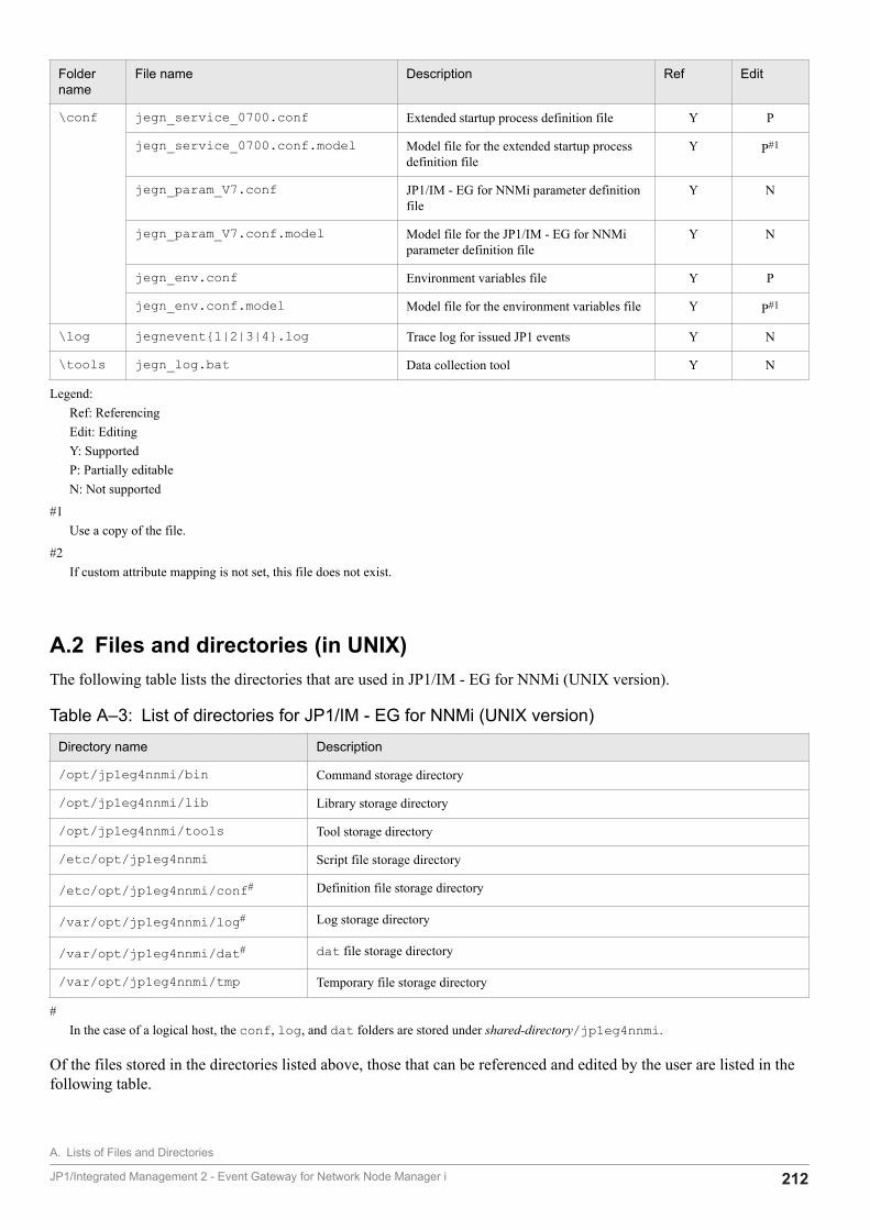
Foldername
File name Description Ref Edit
\conf jegn_service_0700.conf Extended startup process definition file Y P
jegn_service_0700.conf.model Model file for the extended startup processdefinition file
Y P#1
jegn_param_V7.conf JP1/IM - EG for NNMi parameter definitionfile
Y N
jegn_param_V7.conf.model Model file for the JP1/IM - EG for NNMiparameter definition file
Y N
jegn_env.conf Environment variables file Y P
jegn_env.conf.model Model file for the environment variables file Y P#1
\log jegnevent{1|2|3|4}.log Trace log for issued JP1 events Y N
\tools jegn_log.bat Data collection tool Y N
Legend:Ref: ReferencingEdit: EditingY: SupportedP: Partially editableN: Not supported
#1Use a copy of the file.
#2If custom attribute mapping is not set, this file does not exist.
A.2 Files and directories (in UNIX)The following table lists the directories that are used in JP1/IM - EG for NNMi (UNIX version).
Table A‒3: List of directories for JP1/IM - EG for NNMi (UNIX version)
Directory name Description
/opt/jp1eg4nnmi/bin Command storage directory
/opt/jp1eg4nnmi/lib Library storage directory
/opt/jp1eg4nnmi/tools Tool storage directory
/etc/opt/jp1eg4nnmi Script file storage directory
/etc/opt/jp1eg4nnmi/conf# Definition file storage directory
/var/opt/jp1eg4nnmi/log# Log storage directory
/var/opt/jp1eg4nnmi/dat# dat file storage directory
/var/opt/jp1eg4nnmi/tmp Temporary file storage directory
#In the case of a logical host, the conf, log, and dat folders are stored under shared-directory/jp1eg4nnmi.
Of the files stored in the directories listed above, those that can be referenced and edited by the user are listed in thefollowing table.
A. Lists of Files and Directories
JP1/Integrated Management 2 - Event Gateway for Network Node Manager i 212
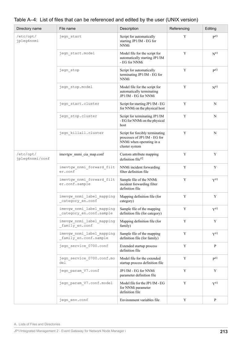
Table A‒4: List of files that can be referenced and edited by the user (UNIX version)
Directory name File name Description Referencing Editing
/etc/opt/jp1eg4nnmi
jegn_start Script for automaticallystarting JP1/IM - EG forNNMi
Y P#3
jegn_start.model Model file for the script forautomatically starting JP1/IM- EG for NNMi
Y N#1
jegn_stop Script for automaticallyterminating JP1/IM - EG forNNMi
Y P#3
jegn_stop.model Model file for the script forautomatically terminatingJP1/IM - EG for NNMi
Y N#1
jegn_start.cluster Script for starting JP1/IM - EGfor NNMi on the physical host
Y N
jegn_stop.cluster Script for terminating JP1/IM- EG for NNMi on the physicalhost
Y N
jegn_killall.cluster Script for forcibly terminatingprocesses of JP1/IM - EG forNNMi when operating in acluster system
Y N
/etc/opt/jp1eg4nnmi/conf
imevtgw_nnmi_cia_map.conf Custom attribute mappingdefinition file#2
Y Y
imevtgw_nnmi_forward_filter.conf
NNMi incident forwardingfilter definition file
Y Y
imevtgw_nnmi_forward_filter.conf.sample
Sample file of the NNMiincident forwarding filterdefinition file
Y Y#1
imevgw_nnmi_label_mapping_category_en.conf
Mapping definition file (forcategory)
Y Y
imevgw_nnmi_label_mapping_category_en.conf.sample
Sample file of the mappingdefinition file (for category)
Y Y#1
imevgw_nnmi_label_mapping_family_en.conf
Mapping definition file (forfamily)
Y Y
imevgw_nnmi_label_mapping_family_en.conf.sample
Sample file of the mappingdefinition file (for family)
Y Y#1
jegn_service_0700.conf Extended startup processdefinition file
Y P
jegn_service_0700.conf.model
Model file for the extendedstartup process definition file
Y P#1
jegn_param_V7.conf JP1/IM - EG for NNMiparameter definition file
Y Y
jegn_param_V7.conf.model Model file for the JP1/IM - EGfor NNMi parameterdefinition file
Y Y#1
jegn_env.conf Environment variables file Y P
A. Lists of Files and Directories
JP1/Integrated Management 2 - Event Gateway for Network Node Manager i 213

Directory name File name Description Referencing Editing
/etc/opt/jp1eg4nnmi/conf
jegn_env.conf.model Model file for the environmentvariables file
Y P#1
/var/opt/jp1eg4nnmi/log
jegnevent{1|2|3|4}.log Trace log for issued JP1 events Y N
/opt/jp1eg4nnmi/tools
jegn_log.sh Data collection tool Y N
Legend:Y: SupportedP: Partially editableN: Not supported
#1Use a copy of the file.
#2If custom attribute mapping is not set, this file does not exist.
#3Only the lines containing the LANG environment variable can be changed.
A. Lists of Files and Directories
JP1/Integrated Management 2 - Event Gateway for Network Node Manager i 214
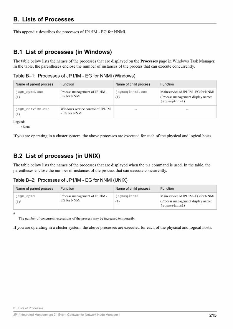
B. Lists of Processes
This appendix describes the processes of JP1/IM - EG for NNMi.
B.1 List of processes (in Windows)The table below lists the names of the processes that are displayed on the Processes page in Windows Task Manager.In the table, the parentheses enclose the number of instances of the process that can execute concurrently.
Table B‒1: Processes of JP1/IM - EG for NNMi (Windows)
Name of parent process Function Name of child process Function
jegn_spmd.exe(1)
Process management of JP1/IM -EG for NNMi
jegneg4nnmi.exe(1)
Main service of JP1/IM - EG for NNMi(Process management display name:jegneg4nnmi)
jegn_service.exe(1)
Windows service control of JP1/IM- EG for NNMi
-- --
Legend:--: None
If you are operating in a cluster system, the above processes are executed for each of the physical and logical hosts.
B.2 List of processes (in UNIX)The table below lists the names of the processes that are displayed when the ps command is used. In the table, theparentheses enclose the number of instances of the process that can execute concurrently.
Table B‒2: Processes of JP1/IM - EG for NNMi (UNIX)
Name of parent process Function Name of child process Function
jegn_spmd(1)#
Process management of JP1/IM -EG for NNMi
jegneg4nnmi(1)
Main service of JP1/IM - EG for NNMi(Process management display name:jegneg4nnmi)
#The number of concurrent executions of the process may be increased temporarily.
If you are operating in a cluster system, the above processes are executed for each of the physical and logical hosts.
B. Lists of Processes
JP1/Integrated Management 2 - Event Gateway for Network Node Manager i 215

C. List of Limit Values
The following table lists the limit values for JP1/IM - EG for NNMi.
Table C‒1: List of limit values
Item Limit value
Maximum size of the NNMi incident forwarding filter definition file 10 MB
Maximum number of forwarding condition blocks that can be specified in the NNMi incident forwardingfilter definition file
100
Maximum size of the mapping definition file (for category) 10 MB
Maximum size of the mapping definition file (for family) 10 MB
C. List of Limit Values
JP1/Integrated Management 2 - Event Gateway for Network Node Manager i 216

D. Performance and Estimation
For details about the memory requirements and the required disk capacity for JP1/IM - EG for NNMi, see the ReleaseNotes.
D. Performance and Estimation
JP1/Integrated Management 2 - Event Gateway for Network Node Manager i 217
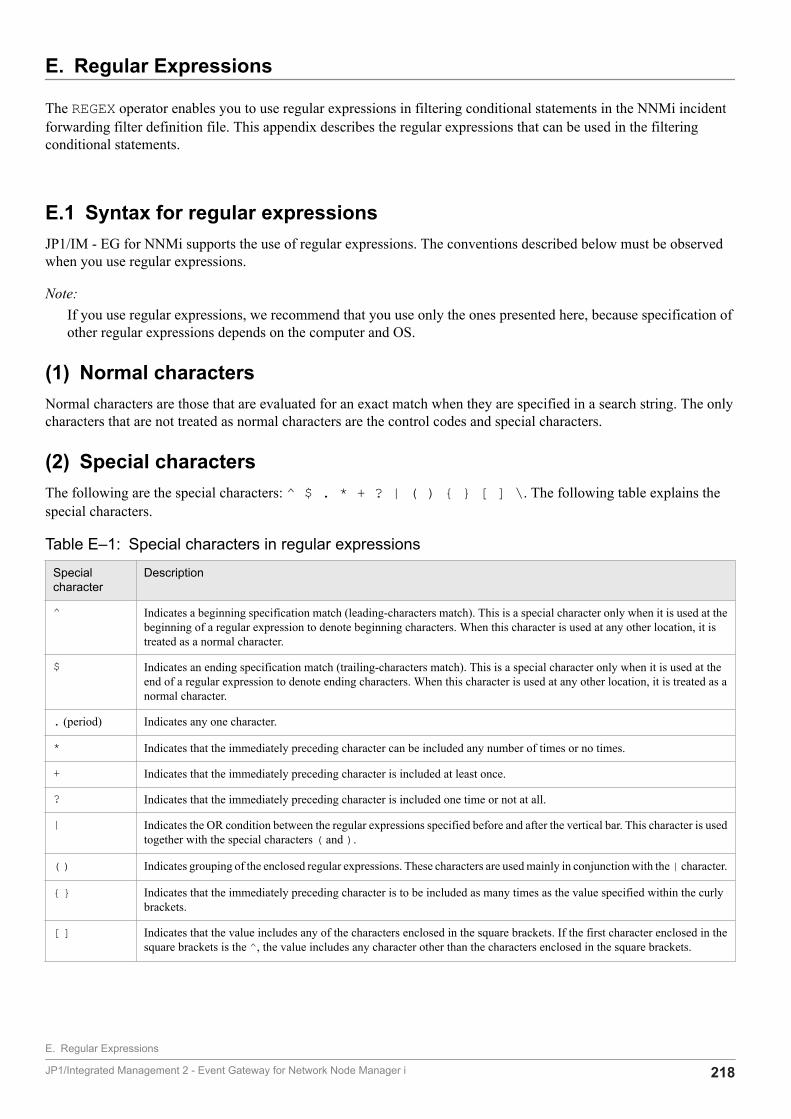
E. Regular Expressions
The REGEX operator enables you to use regular expressions in filtering conditional statements in the NNMi incidentforwarding filter definition file. This appendix describes the regular expressions that can be used in the filteringconditional statements.
E.1 Syntax for regular expressionsJP1/IM - EG for NNMi supports the use of regular expressions. The conventions described below must be observedwhen you use regular expressions.
Note:If you use regular expressions, we recommend that you use only the ones presented here, because specification ofother regular expressions depends on the computer and OS.
(1) Normal charactersNormal characters are those that are evaluated for an exact match when they are specified in a search string. The onlycharacters that are not treated as normal characters are the control codes and special characters.
(2) Special charactersThe following are the special characters: ^ $ . * + ? | ( ) { } [ ] \. The following table explains thespecial characters.
Table E‒1: Special characters in regular expressions
Specialcharacter
Description
^ Indicates a beginning specification match (leading-characters match). This is a special character only when it is used at thebeginning of a regular expression to denote beginning characters. When this character is used at any other location, it istreated as a normal character.
$ Indicates an ending specification match (trailing-characters match). This is a special character only when it is used at theend of a regular expression to denote ending characters. When this character is used at any other location, it is treated as anormal character.
. (period) Indicates any one character.
* Indicates that the immediately preceding character can be included any number of times or no times.
+ Indicates that the immediately preceding character is included at least once.
? Indicates that the immediately preceding character is included one time or not at all.
| Indicates the OR condition between the regular expressions specified before and after the vertical bar. This character is usedtogether with the special characters ( and ).
( ) Indicates grouping of the enclosed regular expressions. These characters are used mainly in conjunction with the | character.
{ } Indicates that the immediately preceding character is to be included as many times as the value specified within the curlybrackets.
[ ] Indicates that the value includes any of the characters enclosed in the square brackets. If the first character enclosed in thesquare brackets is the ^, the value includes any character other than the characters enclosed in the square brackets.
E. Regular Expressions
JP1/Integrated Management 2 - Event Gateway for Network Node Manager i 218
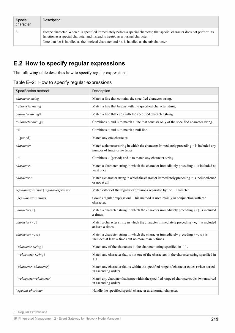
Specialcharacter
Description
\ Escape character. When \ is specified immediately before a special character, that special character does not perform itsfunction as a special character and instead is treated as a normal character.Note that \n is handled as the linefeed character and \t is handled as the tab character.
E.2 How to specify regular expressionsThe following table describes how to specify regular expressions.
Table E‒2: How to specify regular expressions
Specification method Description
character-string Match a line that contains the specified character string.
^character-string Match a line that begins with the specified character string.
character-string$ Match a line that ends with the specified character string.
^character-string$ Combines ^ and $ to match a line that consists only of the specified character string.
^$ Combines ^ and $ to match a null line.
. (period) Match any one character.
character* Match a character string in which the character immediately preceding * is included anynumber of times or no times.
.* Combines . (period) and * to match any character string.
character+ Match a character string in which the character immediately preceding + is included atleast once.
character? Match a character string in which the character immediately preceding ? is included onceor not at all.
regular-expression|regular-expression Match either of the regular expressions separated by the | character.
(regular-expressions) Groups regular expressions. This method is used mainly in conjunction with the |character.
character{n} Match a character string in which the character immediately preceding {n} is includedn times.
character{n,} Match a character string in which the character immediately preceding {n,} is includedat least n times.
character{n,m} Match a character string in which the character immediately preceding {n,m} isincluded at least n times but no more than m times.
[character-string] Match any of the characters in the character string specified in [ ].
[^character-string] Match any character that is not one of the characters in the character string specified in[ ].
[character-character] Match any character that is within the specified range of character codes (when sortedin ascending order).
[^character-character] Match any character that is not within the specified range of character codes (when sortedin ascending order).
\special-character Handle the specified special character as a normal character.
E. Regular Expressions
JP1/Integrated Management 2 - Event Gateway for Network Node Manager i 219
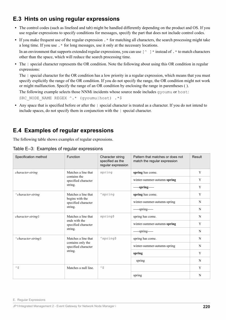
E.3 Hints on using regular expressions• The control codes (such as linefeed and tab) might be handled differently depending on the product and OS. If you
use regular expressions to specify conditions for messages, specify the part that does not include control codes.
• If you make frequent use of the regular expression .* for matching all characters, the search processing might takea long time. If you use .* for long messages, use it only at the necessary locations.In an environment that supports extended regular expressions, you can use [^ ]* instead of .* to match charactersother than the space, which will reduce the search processing time.
• The | special character represents the OR condition. Note the following about using this OR condition in regularexpressions:The | special character for the OR condition has a low priority in a regular expression, which means that you mustspecify explicitly the range of the OR condition. If you do not specify the range, the OR condition might not workor might malfunction. Specify the range of an OR condition by enclosing the range in parentheses ( ).The following example selects those NNMi incidents whose source node includes gyoumu or host:SRC_NODE_NAME REGEX ^.* (gyoumu|host) .*$
• Any space that is specified before or after the | special character is treated as a character. If you do not intend toinclude spaces, do not specify them in conjunction with the | special character.
E.4 Examples of regular expressionsThe following table shows examples of regular expressions.
Table E‒3: Examples of regular expressions
Specification method Function Character stringspecified as theregular expression
Pattern that matches or does notmatch the regular expression
Result
character-string Matches a line thatcontains thespecified characterstring.
spring spring has come. Y
winter-summer-autumn-spring Y
-----spring----- Y
^character-string Matches a line thatbegins with thespecified characterstring.
^spring spring has come. Y
winter-summer-autumn-spring N
-----spring----- N
character-string$ Matches a line thatends with thespecified characterstring.
spring$ spring has come. N
winter-summer-autumn-spring Y
-----spring----- N
^character-string$ Matches a line thatcontains only thespecified characterstring.
^spring$ spring has come. N
winter-summer-autumn-spring N
spring Y
spring N
^$ Matches a null line. ^$ Y
spring N
E. Regular Expressions
JP1/Integrated Management 2 - Event Gateway for Network Node Manager i 220
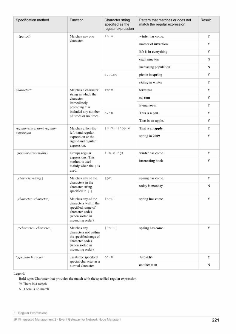
Specification method Function Character stringspecified as theregular expression
Pattern that matches or does notmatch the regular expression
Result
. (period) Matches any onecharacter.
in.e winter has come. Y
mother of invention Y
life is in everything Y
eight nine ten N
increasing population N
s..ing picnic in spring Y
skiing in winter Y
character* Matches a characterstring in which thecharacterimmediatelypreceding * isincluded any numberof times or no times.
ro*m terminal Y
cd-rom Y
living room Y
h.*n This is a pen. Y
That is an apple. Y
regular-expression|regular-expression
Matches either theleft-hand regularexpression or theright-hand regularexpression.
[0-9]+|apple That is an apple. Y
spring in 2009 Y
(regular-expressions) Groups regularexpressions. Thismethod is usedmainly when the | isused.
i(n.e|ng) winter has come. Y
interesting book Y
[character-string] Matches any of thecharacters in thecharacter stringspecified in [ ].
[pr] spring has come. Y
today is monday. N
[character-character] Matches any of thecharacters within thespecified range ofcharacter codes(when sorted inascending order).
[a-i] spring has come. Y
[^character-character] Matches anycharacters not withinthe specified range ofcharacter codes(when sorted inascending order).
[^a-i] spring has come. Y
\special-character Treats the specifiedspecial character as anormal character.
o\.h <stdio.h> Y
another man N
Legend:Bold type: Character that provides the match with the specified regular expressionY: There is a matchN: There is no match
E. Regular Expressions
JP1/Integrated Management 2 - Event Gateway for Network Node Manager i 221
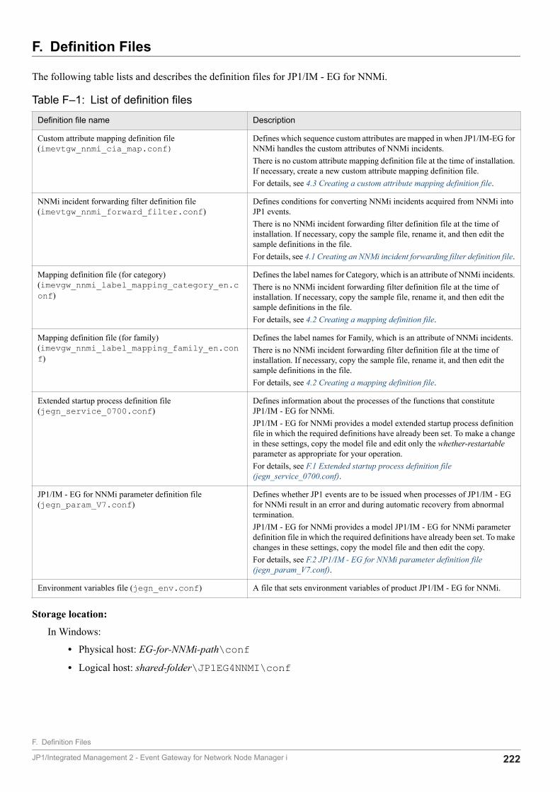
F. Definition Files
The following table lists and describes the definition files for JP1/IM - EG for NNMi.
Table F‒1: List of definition files
Definition file name Description
Custom attribute mapping definition file(imevtgw_nnmi_cia_map.conf)
Defines which sequence custom attributes are mapped in when JP1/IM-EG forNNMi handles the custom attributes of NNMi incidents.There is no custom attribute mapping definition file at the time of installation.If necessary, create a new custom attribute mapping definition file.For details, see 4.3 Creating a custom attribute mapping definition file.
NNMi incident forwarding filter definition file(imevtgw_nnmi_forward_filter.conf)
Defines conditions for converting NNMi incidents acquired from NNMi intoJP1 events.There is no NNMi incident forwarding filter definition file at the time ofinstallation. If necessary, copy the sample file, rename it, and then edit thesample definitions in the file.For details, see 4.1 Creating an NNMi incident forwarding filter definition file.
Mapping definition file (for category)(imevgw_nnmi_label_mapping_category_en.conf)
Defines the label names for Category, which is an attribute of NNMi incidents.There is no NNMi incident forwarding filter definition file at the time ofinstallation. If necessary, copy the sample file, rename it, and then edit thesample definitions in the file.For details, see 4.2 Creating a mapping definition file.
Mapping definition file (for family)(imevgw_nnmi_label_mapping_family_en.conf)
Defines the label names for Family, which is an attribute of NNMi incidents.There is no NNMi incident forwarding filter definition file at the time ofinstallation. If necessary, copy the sample file, rename it, and then edit thesample definitions in the file.For details, see 4.2 Creating a mapping definition file.
Extended startup process definition file(jegn_service_0700.conf)
Defines information about the processes of the functions that constituteJP1/IM - EG for NNMi.JP1/IM - EG for NNMi provides a model extended startup process definitionfile in which the required definitions have already been set. To make a changein these settings, copy the model file and edit only the whether-restartableparameter as appropriate for your operation.For details, see F.1 Extended startup process definition file(jegn_service_0700.conf).
JP1/IM - EG for NNMi parameter definition file(jegn_param_V7.conf)
Defines whether JP1 events are to be issued when processes of JP1/IM - EGfor NNMi result in an error and during automatic recovery from abnormaltermination.JP1/IM - EG for NNMi provides a model JP1/IM - EG for NNMi parameterdefinition file in which the required definitions have already been set. To makechanges in these settings, copy the model file and then edit the copy.For details, see F.2 JP1/IM - EG for NNMi parameter definition file(jegn_param_V7.conf).
Environment variables file (jegn_env.conf) A file that sets environment variables of product JP1/IM - EG for NNMi.
Storage location:
In Windows:
• Physical host: EG-for-NNMi-path\conf• Logical host: shared-folder\JP1EG4NNMI\conf
F. Definition Files
JP1/Integrated Management 2 - Event Gateway for Network Node Manager i 222
In UNIX:
• Physical host: /etc/opt/jp1eg4nnmi/conf• Logical host: shared-directory/jp1eg4nnmi/conf
F.1 Extended startup process definition file (jegn_service_0700.conf)Format
process-name|path|start-options|whether-restartable|restart-count|retry-interval|restart-count-reset-time
Filesjegn_service_0700.conf (extended startup process definition file)jegn_service_0700.conf.model (model file for the extended startup process definition file)
DescriptionThe extended startup process definition file defines information about the processes of the functions that constituteJP1/IM - EG for NNMi.JP1/IM - EG for NNMi uses the process management function to control restart in the event of abnormal terminationof a process. The process management function controls the processes according to definitions in the extended startupprocess definition file.JP1/IM - EG for NNMi provides a model extended startup process definition file in which the required definitionshave already been set. To make a change in these settings, copy the model file and edit only the whether-restartableparameter as appropriate for your operation. Normally, there is no need to change any of the other parameter settingsbecause appropriate values have already been set as the defaults for each process.Do not specify any unneeded characters, such as spaces. Edit only the value of the whether-restartable parameter.In the case of a cluster configuration, if the extended startup process definition file is not found in the conf folderat the logical host when a process of process management is started at the logical host, the extended startup processdefinition file at the physical host is copied.
When the definitions are appliedThe settings in this definition file take effect when JP1/IM - EG for NNMi starts or when the jegn_spmd_reloadcommand is executed to reload the definitions. For details about thejegn_spmd_reload command, seejegn_spmd_reload in 7. Commands.
Information to be specified
process-nameSpecifies the name of a process that is to be started and terminated by the process management function of JP1/IM - EG for NNMi.Do not edit this parameter because the process names of JP1/IM - EG for NNMi have already been specified.The process names are displayed by the jegn_spmd_status command.
pathSpecifies the absolute path of the process's executable file.Do not edit this parameter because the paths of the JP1/IM - EG for NNMi processes have already been specified.
start-optionsSpecifies start options for the process.Do not edit this parameter because the start options have already been specified for the applicable processes.
F. Definition Files
JP1/Integrated Management 2 - Event Gateway for Network Node Manager i 223
whether-restartableSpecifies whether the process is to be restarted if it terminates abnormally.To restart the process, specify 0; to not restart the process, specify 1.The default is 0.
restart-countSpecifies the retry count for process restarts.The permitted value is from 0 to 99. The default is 3.If 0 is specified in the whether-restartable field, this parameter is ignored even when a value is specified.
retry-intervalSpecifies the retry interval in seconds for process restarts.The permitted value is from 0 to 3600. The default is 3.If 0 is specified in the whether-restartable field, this parameter is ignored even when a value is specified.
restart-count-reset-timeSpecifies the amount of time in seconds that must elapse after a restart of the process before the restart count isreset.The permitted value is from 3600 to 2147483647. The default is 21600.When the specified time elapses since the process restarted, the restart count is reset. If the process terminatesabnormally again thereafter, the restart count begins again with 1. If the process is started by a restart butterminates abnormally again before the specified time has elapsed, the previous restart count is inherited.If 0 is specified in the whether-restartable field, this parameter is ignored even when a value is specified.
Notes
In case of operation using a cluster systemDo not restart JP1 by JP1 process management. Restart JP1 by the cluster software.
F.2 JP1/IM - EG for NNMi parameter definition file (jegn_param_V7.conf)Format
[logical-host-name\JP1EG4NNMI]"SEND_PROCESS_TERMINATED_ABNORMALLY_EVENT"=dword:value"SEND_PROCESS_RESTART_EVENT"=dword:value
Filesjegn_param_V7.conf (JP1/IM - EG for NNMi parameter definition file)jegn_param_V7.conf.model (model file for the JP1/IM - EG for NNMi parameter definition file)
DescriptionThe JP1/IM - EG for NNMi parameter definition file defines whether JP1 events are to be issued in the event of anerror in a JP1/IM - EG for NNMi process and during automatic recovery from abnormal termination. By issuingJP1 events in the event of a process error and during automatic recovery from abnormal termination, you can managethe error logs of problems that occurred in JP1/IM - EG for NNMi. We recommend that you use this definition fileto specify that JP1 events are to be issued.JP1/IM - EG for NNMi provides a model JP1/IM - EG for NNMi parameter definition file in which the requireddefinitions have already been set. To make changes in these settings, copy the model file and then edit the copy.The following shows the processes of JP1/IM - EG for NNMi and the JP1 events that can be issued.
F. Definition Files
JP1/Integrated Management 2 - Event Gateway for Network Node Manager i 224
Processes of JP1/IM - EG for NNMi
• Process management of JP1/IM - EG for NNMi (jegn_spmd)
• Main service of JP1/IM - EG for NNMi (jegneg4nnmi)
JP1 events that can be issued
Event ID Issuance timing
0x000061F0 When a process terminates abnormally
0x000061F1 When startup of a process results in a timeout
0x000061F2 When a process that terminated abnormally has restarted
For details about the JP1 events, see 8.4.2 Details of JP1 events.
When the definitions are appliedThe settings in this definition file take effect after JP1/IM - EG for NNMi is restarted by executing the jbssetcnfcommand of JP1/Base with this definition file specified in an argument. For details about the jbssetcnfcommand, see the JP1/Base User's Guide.
Information to be specified
[logical-host-name\JP1EG4NNMI]This is a key name of the environment settings for JP1/IM - EG for NNMi.Set in logical-host-name either JP1_DEFAULT for the physical host or the logical host name for the logicalhost.
"SEND_PROCESS_TERMINATED_ABNORMALLY_EVENT"=dword:valueSpecify 1 in value in order for JP1 events to be issued at the following times:
• When a process terminates abnormallyThe JP1 event whose event ID is 0x000061F0 is issued.
• When no start notification is sent during startup and a timeout occursThe JP1 event whose event ID is 0x000061F1 is issued.
The default is 0, in which case these JP1 events are not issued.
"SEND_PROCESS_RESTART_EVENT"=dword:valueSpecify 1 in value in order for a JP1 event to be issued at the following time:
• When a process that terminated abnormally is restarted by the process restart functionThe JP1 event whose event ID is 0x000061F2 is issued.
The default is 0, in which case this JP1 event is not issued.
F. Definition Files
JP1/Integrated Management 2 - Event Gateway for Network Node Manager i 225

G. Version Changes
This appendix describes the changes between versions.
G.1 Changes in version 12-00
(1) Changes in the manual 3021-3-D57(E)• The following operating system is no longer supported:
• Windows Server 2008 R2
• It corresponds to TLSv1.2 by https connection with NNMi. Accordingly, changed the notation of SSL to the notationof TLS.
• The information was increased that can be obtained with data collection tool.
G.2 Changes in version 11-50
(1) Changes in the manual 3021-3-A13-10(E)None.
G. Version Changes
JP1/Integrated Management 2 - Event Gateway for Network Node Manager i 226
H. Reference Material for this Manual
This appendix provides reference material for readers of this manual.
H.1 Related publicationsThis manual is part of a related set of manuals. The manuals in the set are listed below (with the manual numbers):
Manuals related to JP1
• JP1 Version 12 JP1/Base User's Guide (3021-3-D65(E))
• JP1 Version 12 JP1/Base Messages (3021-3-D66(E))
• JP1 Version 12 JP1/Base Function Reference (3021-3-D67(E))
• Job Management Partner 1/Software Distribution Setup Guide (3020-3-S80(E)), for Windows systems
• Job Management Partner 1/Software Distribution Administrator's Guide Volume 1 (3020-3-S81(E)), forWindows systems
• Job Management Partner 1/Software Distribution Client Description and User's Guide (3020-3-S85(E)), forUNIX systems
Manuals related to JP1/IM
• JP1 Version 12 Integrated Management 2: Getting Started (3021-3-D50(E))
• JP1 Version 12 JP1/Integrated Management 2 - Manager Overview and System Design Guide (3021-3-D51(E))
• JP1 Version 12 JP1/Integrated Management 2 - Manager Configuration Guide (3021-3-D52(E))
• JP1 Version 12 JP1/Integrated Management 2 - Manager Administration Guide (3021-3-D53(E))
• JP1 Version 12 JP1/Integrated Management 2 - Manager GUI Reference (3021-3-D54(E))
• JP1 Version 12 JP1/Integrated Management 2 - Manager Command and Definition File Reference (3021-3-D55(E))
• JP1 Version 12 JP1/Integrated Management 2 - Manager Messages (3021-3-D56(E))
• JP1 Version 11 Integrated Management: Getting Started (Integrated Console) (3021-3-A06(E))
• JP1 Version 11 JP1/Integrated Management - Manager Overview and System Design Guide (3021-3-A07(E))
• JP1 Version 11 JP1/Integrated Management - Manager Configuration Guide (3021-3-A08(E))
• JP1 Version 11 JP1/Integrated Management - Manager Administration Guide (3021-3-A09(E))
• JP1 Version 11 JP1/Integrated Management - Manager GUI Reference (3021-3-A10(E))
• JP1 Version 11 JP1/Integrated Management - Manager Command and Definition File Reference (3021-3-A11(E))
• JP1 Version 11 JP1/Integrated Management - Manager Messages (3021-3-A12(E))
H.2 Conventions: AbbreviationsThis manual uses the following abbreviations for the names of Hitachi products and other products:
H. Reference Material for this Manual
JP1/Integrated Management 2 - Event Gateway for Network Node Manager i 227
Abbreviation Full name or meaning
JP1/IM JP1/IM - Manager JP1/Integrated Management - Manager
JP1/Integrated Management 2 - Manager
JP1/IM - View JP1/Integrated Management - View
JP1/Integrated Management 2 - View
JP1/IM - EG for NNMi JP1/Integrated Management - Event Gateway forNetwork Node Manager i
JP1/Integrated Management 2 - Event Gateway forNetwork Node Manager i
Linux CentOS 6 (x64) CentOS 6 (x64)
CentOS 7 CentOS 7
Linux 6 (x64) Red Hat Enterprise Linux(R) Server 6 (64-bitx86_64)
Linux 7 Red Hat Enterprise Linux(R) Server 7
Oracle Linux 6 (x64) Oracle Linux(R) Operating System 6 (x64)
Oracle Linux 7 Oracle Linux(R) Operating System 7
SUSE Linux 12 SUSE Linux(R) Enterprise Server 12
NNMi JP1/NNMi JP1/Network Node Manager i 11-00 or later
JP1/NNMi Advanced JP1/Network Node Manager i Advanced 11-00 orlater
In this manual, Linux is generally referred to as UNIX.
H.3 AcronymsThis manual also uses the following abbreviations:
Abbreviation Full name or meaning
AP Application Program
API Application Programming Interface
DB Database
FTP File Transfer Protocol
GUI Graphical User Interface
ID Identification number
IP Internet Protocol
MSCS Microsoft Cluster Service
OS Operating System
PC Personal Computer
SNMP Simple Network Management Protocol
SSL Secure Socket Layer
H. Reference Material for this Manual
JP1/Integrated Management 2 - Event Gateway for Network Node Manager i 228
Abbreviation Full name or meaning
TLS Transport Layer Security
URL Uniform Resource Locator
WWW World Wide Web
H.4 Conventions: KB, MB, GB and TBThis manual uses the following conventions:
• 1 KB (kilobyte) is 1,024 bytes.
• 1 MB (megabyte) is 1,0242 bytes.
• 1 GB (gigabyte) is 1,0243 bytes.
• 1 TB (terabyte) is 1,0244 bytes.
H. Reference Material for this Manual
JP1/Integrated Management 2 - Event Gateway for Network Node Manager i 229
I. Glossary
agentA program that is managed by another program in the system or a host that is managed by another host inthe system. JP1/IM - EG for NNMi is installed on an agent host.
basic attributeA type of information item (attribute) of JP1 events that characterizes all JP1 events.
See JP1 event.
cluster systemA system in which multiple servers are linked and operated as a single system.
The purpose of a cluster system is to improve availability by enabling application processing to betransferred to another server in the event of a failure in the executing server. Such transfer of processing iscalled a failover.
If a failure occurs on the server that is executing an application (primary node), the standby server(secondary node) inherits the application. This is also called a node switching system because it involvesswitching of the application processing from the primary node to the secondary node.
There is also a type of cluster system that is configured to distribute the workload by running multipleservers in parallel. However, in this manual, cluster system refers to the configuration that supports failoverin order to prevent interruption of application processing.
common definition informationA database that stores the definition parameters for the JP1 execution environment and that is managed byJP1/Base. This database is located on each server's local disk. It contains the definition parameters for thephysical host and the logical host separately.
When JP1 is operated in a cluster system, the logical host definition contained in the common definitioninformation must be the same between the servers of the primary and secondary nodes. Therefore, whensetup and environment setup are performed, the parameters are set on the active server and then thosesettings are copied to the standby server.
conditional statementA filtering conditional statement that is used to include as conversion targets those NNMi incidents thatsatisfy a specified condition. The conditional statements are specified in the filter condition block in theNNMi incident forwarding filter definition file.
Event Console windowA JP1/IM - View window that displays the JP1 events received by the central console arranged in the orderreceived (by time). This is the first window displayed when you log in to JP1/IM - Central Console.
JP1/IM uses JP1 events to record the events that occur at each host and facilitates centralized managementby transferring the important JP1 events to JP1/IM's manager host. By displaying these JP1 events in theEvent Console window, you can monitor centrally the significant events that have occurred in the system.
I. Glossary
JP1/Integrated Management 2 - Event Gateway for Network Node Manager i 230
event IDA JP1 event attribute that identifies the program that issued the JP1 event and that indicates the nature ofthe event. The event ID is a basic attribute of JP1 events and its attribute name is B.ID.
The event ID is expressed in hexadecimal, such as 7FFF8000.
Unique event IDs are assigned to each JP1-series product. For details about the JP1 events that are issuedby each JP1-series product, see the appropriate documentation for each product.
Event IDs that can be used by the user are from 0 to 1FFF and from 7FFF8000 to 7FFFFFFF.
The details of JP1 events are indicated by an 8-byte numeric value that consists of the basic code (leading4 bytes) and an extended code (trailing 4 bytes). Normally, only the 4-byte basic code is used. The extendedcode is set to 0 except when the user uses the API to set a code. When specification of both basic andextended codes is needed, they are connected by a colon (:), such as 7FFF8000:0.
event serverA program that provides functions for managing JP1 events in JP1/Base. JP1 events can be collected anddistributed while the event server is running.
event serviceA function for registering and managing as JP1 events the events that occur in the system.
exclusion conditionA filtering conditional statement that is used to exclude as conversion targets those NNMi incidents thatsatisfy a specified condition. The exclusion conditions are specified in the filter condition block in theNNMi incident forwarding filter definition file.
extended attributeA type of information item (attribute) of JP1 events that is specified by the programs that issue events.
See JP1 event.
failoverA function for ensuring uninterrupted processing by switching JP1 to another normal server in the eventof a failure on the server where JP1 is running. Failover can also refer to switching of the servers that runJP1 by an action of a system administrator.
This is also referred to as node switching, because failover occurs from the active server to the standbyserver.
incidentA single failure event that has an adverse effect on the quality of IT services and prevents normal systemoperation.
JP1 common definition informationSee common definition information.
JP1 eventInformation used in JP1 to manage events that occur in the system.
I. Glossary
JP1/Integrated Management 2 - Event Gateway for Network Node Manager i 231
JP1 events use the following attributes to record events:
• Basic attributesAll JP1 events have basic attributes.For example, when attribute names are specified, B.ID (or just ID) is specified for the event ID.
• Extended attributesA program that issues JP1 events can specify any desired extended attributes. The extended attributesconsist of the following common information and program-specific information:• Common information (extended attribute information whose format is standardized according to theJP1 event)• Program-specific information (information other than the common information whose format isspecific to a program)For example, when attribute names are specified, E.SEVERITY (or just SEVERITY) is specified forthe severity.
The JP1 events are managed by the event service of JP1/Base. Events that occur in the system are recordedin the database as JP1 events.
JP1/BaseThe program that provides the event service. JP1/Base can be used to control the service startup sequenceand to send and receive JP1 events. JP1/Base is a prerequisite program for JP1/IM - EG for NNMi.
JP1/IM - ManagerA program used to achieve integrated management of systems by providing for centralized monitoring andoperation of the entire system.
JP1/IM - ViewThe program that provides the viewer function (GUI) for enabling integrated management of systems inJP1/IM.
JP1/NNMiA collective name for integrated network management programs that manage the network configuration,performance, and failures.
JP1/Power MonitorA program used to start and terminate hosts automatically. JP1/Power Monitor enables the user to start andterminate hosts on the basis of schedules, as well as to start and terminate remote hosts.
JP1/Software DistributionA collective name for systems that use a network to perform software distribution and client managementin the batch mode.
jp1hosts informationThe hosts information that defines the correspondences between JP1-specific host names and IPaddresses.
This information is used to customize JP1 communication operations in an environment that is connectedto multiple networks. JP1/Base manages the jp1hosts information.
I. Glossary
JP1/Integrated Management 2 - Event Gateway for Network Node Manager i 232
jp1hosts information does not support communication using IPv6 addresses. To use IPv6 addresses forcommunication, you must set jp1hosts2 information.
See jp1hosts2 information.
During JP1 communication, the jp1hosts information has precedence over other information, such ashosts. This enables JP1-specific correspondences between host names and IP addresses that differ fromthe settings in the OS to be used for communication.
jp1hosts2 informationThe hosts information that defines the correspondences between JP1-specific host names and IPaddresses.
This information is used to customize JP1 communication operations in an environment that is connectedto multiple networks. JP1/Base manages the jp1hosts2 information.
To use IPv6 addresses for communication, you must set jp1hosts2 information.
During JP1 communication, the jp1hosts2 information has precedence over other information, such ashosts. This enables JP1-specific correspondences between host names and IP addresses that differ fromthe settings in the OS to be used for communication.
Note that JP1/IM - EG for NNMi supports IPv4/IPv6 mixed environment (dual-stack environment),however, it does not support an environment with IPv6 only.
logical hostA logical server that becomes the JP1 execution environment when JP1 is operating in a cluster system.This is also the unit of failover in the event of a failure.
A logical host has a logical IP address and a shared disk that are inherited during failover. It consists ofapplications, such as JP1 programs, that are run using the logical IP address and shared disk.
In the event of failover, the logical IP address and shared disk are transferred for continuation of JP1execution. As a result, although the physical server running JP1 has changed, other hosts can still use thesame IP address to access the server as if there had been no change in the operating host.
managerA program whose role is to manage other programs in the system, or a host whose role is to manage otherhosts in the system.
The JP1 events issued by JP1/IM - EG for NNMi are managed by the JP1/IM - Manager that is installedon the manager host.
NNMi incidentA single error event that is reported when something unintended occurs in a network device managed byJP1/NNMi.
node switching systemSee cluster system.
I. Glossary
JP1/Integrated Management 2 - Event Gateway for Network Node Manager i 233

physical hostThe physical server in a cluster system (when JP1 is operating in the cluster system). In addition to thephysical host, there are also logical hosts (so that a logical server can fail over without depending on thephysical server).
severityOne of the attributes of JP1 events that indicates the seriousness of events in the system.
Severity belongs to the common information of the extended attributes of JP1 events. Its attribute name isE.SEVERITY.
The severity levels include Emergency, Alert, Critical, Error, Warning, Notice,Information, and Debug.
viewerA program that provides appropriate GUI-based windows for achieving integrated management of JP1/IMsystems. Viewer also refers to the host that runs the viewer.
I. Glossary
JP1/Integrated Management 2 - Event Gateway for Network Node Manager i 234
Index
Aabnormal process termination
setting JP1 event issuance in event of 32settings for restarting after 31
agent 17, 230applicable OS 17attribute of NNMi incident 51automated startup script 30automated stop script 30automatic startup, setting 29automatic termination, setting 29
Bbasic attribute 107, 230
Cchanging
host name 79IP address 79port number 79system date and time 79time zone 80
cluster system 230chaging logical host name 79deleting logical host 44environment setup procedure 35installing and setting up active server 37installing and setting up logical host 37installing and setting up standby server 38notes about cluster operation 45operation and environment configuration 34procedure for changing settings 39registering into cluster software 40
commands 83format of explanations of 84jegn_killall.cluster (UNIX) 86jegn_log.bat (Windows) 87jegn_log.sh (UNIX) 89jegn_setup 92jegn_setup_cluster 97jegn_spmd_reload 98jegn_spmd_status 100jegn_start.cluster (UNIX) 103jegn_start (UNIX) 102
jegn_stop.cluster (UNIX) 105jegn_stop (UNIX) 104lists of 85startup, termination, and setup 85troubleshooting 85
common definition information 230conditional statement 49, 230conventions
diagrams 6fonts and symbols 7
conversion procedure 19custom attribute mapping definition file
creating 63format of 64name and storage location of 63
Ddata collection tool 193definition files 222
custom attribute mapping definition file 63definition file for executing applications 71definition file for extended event attributes 66definition file for opening monitor windows 70editing 78editing JP1/IM - Manager 66extended startup process definition file 223JP1/IM - EG for NNMi parameter definition file 224mapping definition file 61NNMi incident forwarding filter definition file 47setting 29
details of event ID0x00006100 1140x000061F0 1140x000061F1 1150x000061F2 115
diagram conventions 6directories, list of 212
Eediting
definition file 78hosts file 79jp1hosts2 definition file 79jp1hosts definition file 79
JP1/Integrated Management 2 - Event Gateway for Network Node Manager i 235
error, settings for handling 31Event Console window 230event ID 231event server 231event service 231exclusion condition 49, 231extended attribute 107, 231
checking mapping result of 59common information 107mapping 58program-specific information 107total size of 59
extended startup process definition file 223
Ffailover 231files, list of
UNIX 212Windows 211
filter condition block 49example of 55format of 49
folders, list of 211font conventions 7
Gglossary 230
HHitachi Program Product Installer, using 25host name, changing 79hosts file, editing 79
Iincident 231installation 21
procedure in UNIX 24procedure in Windows 22
internal attribute, displaying 69IP address, changing 79
Jjegn_killall.cluster (UNIX) 86jegn_log.bat (Windows) 87jegn_log.sh (UNIX) 89
jegn_setup 92jegn_setup_cluster 97jegn_spmd_reload 98jegn_spmd_status 100jegn_start.cluster (UNIX) 103jegn_start (UNIX) 102jegn_stop.cluster (UNIX) 105jegn_stop (UNIX) 104JP1/Base 232JP1/IM - EG for NNMi 15
applicable OS 17overview of operation using 16parameter definition file 224prerequisite program 18starting 73system configuration 17terminating 74
JP1/IM - Manager 232editing definition file 66
JP1/IM - View 232JP1/NNMi 232JP1/Power Monitor 30, 232JP1/Software Distribution 232
remote installation in UNIX 24remote installation in Windows 22
JP1 common definition information 231JP1 event 231JP1 events 106
attributes of 107basic attribute 107converting NNMi incidents into 46details of 114extended attribute 107issued by JP1/IM - EG for NNMi 113list of 114obtained by converting NNMi incidents 108
jp1hosts2 definition file, editing 79jp1hosts2 information 233jp1hosts definition file, editing 79jp1hosts information 232
Llimit values, list of 216logical host 233
deleting 44installing and setting up 37
log information, types of 188
JP1/Integrated Management 2 - Event Gateway for Network Node Manager i 236
Mmanager 17, 233mapping block 56
extended attribute mapping 58message mapping 56severity mapping 57
mapping definition filecreating 61format of 61name and storage location of 61
memory requirements 217message mapping 56messages 116
command execution 128editing 56format of explanations of 123installation 125KAVB3501 to KAVB3999 160KNAG0001 to KNAG0999 125KNAG1000 to KNAG1999 128KNAG2000 to KNAG2999 143list of 125maximum size of 57output destinations 117output destinations of, related to commandexecution 117output destinations of, related to installation 117output destinations of, related to processmanagement 119output destinations of, related to services 118output format of 123process management 160services 143
NNNMi incident 15, 233
attribute of 51attribute value of 53conversion procedure 19converting, into JP1 event 46
NNMi incident forwarding filter definition filecreating 47defining filter condition block 49defining mapping block 56definition example 59format of 47
operand 50operator 50sample file 59
node switching system 233Notes regarding operation 82
Ooperand 50operation, overview of 16operator 50overwrite installation and upgrade installation
UNIX 24Windows 22
overwrite setup 29
Pperformance and estimation 217physical host 234port number, changing 79prerequisite program 18primary data
UNIX 89Windows 87
processes, list of 215
Rregular expression 218
example of 220hints on using 220specifying 219syntax for 218
remote installationUNIX 24Windows 22
required disk capacity 217
Ssecondary data
UNIX 89Windows 87
settingJP1 event issuance in event of abnormal processtermination 32preparation for collecting data in event of error(Windows) 31restart after abnormal process termination 31
JP1/Integrated Management 2 - Event Gateway for Network Node Manager i 237
suppressing error reporting to Microsoft 32settings
backing up 76changing 78restoring 76
setup 21, 28severity 234
mapping 57starting 73start sequence definition file 30startup control 30symbol conventions 7syntax conventions 8system administrator, notes for 124system configuration 17system date and time, changing 79
Tterminating 74time zone, changing 80trace log
for each process 192for issued JP1 events 189integrated 188
troubleshooting 186command 85data to be collected in UNIX 200data to be collected in Windows 193primary data for UNIX 89primary data for Windows 87procedure 187secondary data for UNIX 89secondary data for Windows 87types of log information 188
Uuninstallation
procedure in UNIX 24procedure in Windows 23
Vviewer 17, 234
JP1/Integrated Management 2 - Event Gateway for Network Node Manager i 238

6-6, Marunouchi 1-chome, Chiyoda-ku, Tokyo, 100‒8280 Japan