jp4000 joystick control system -...
TRANSCRIPT
JP4000Joystick Control System

2
The JP4000 is a new and innovative solution for mega-yachts (as well as for multi-purpose vessels) covering mooring, docking and low-speed manoeuvring, to make operations more safe and comfortable. The JP4000 has been designed especially for those ship owners who highly appreciate the safety of manoeuvring and full control over vessel motion, irrespective of weather conditions and the area available for manoeuvring.
Modern technology, combined with the latest achievements in the field of dynamic positioning, make the JP4000 Joystick Autopilot system an ideal solution for your vessel, allowing you to discover the full potential of your super-yacht and to enjoy its manoeuvrability.
The JP4000 has been specifically designed for yacht and workboat applications when free manoeuvring in limited space is required; it conforms to the requirements set for Dynamic Positioning Systems of the ABS DPS-0, DPS-1 and DNV-AUT classes. Please note that the system is not intended for use on any DP (Dynamic Positioning) classed vessel as an approved solution for dynamic positioning. In such a case, the range of Navis IVCS/NavDP4000 series products has to be considered.
The JP4000 is recommended for vessels of up to 60 meters in length (LOA).
Introduction
© S
tep
hen
Crid
land

3
When a yacht is moving forward at high speed, the JP4000 acts as the autopilot, providing the vessel heading control by using rudder (-s) or track control by using an external track controller. In the autopilot mode the thrusters and the main propulsion are not affected. The AP4000 autopilot is an integral part of the JP4000 system
The joystick control modes of the JP4000 enable the ship’s master to steer the yacht freely in any direction by manu-ally setting the required fore-and-aft and transverse forces and rotation moment necessary with the help of the 3-axis joystick. The system calculates the amount of thrust to be allocated for every actuator, to replace conventional controls with the joystick at low speeds.
The JP4000 also provides semi-automatic heading control, which means that the system automatically holds the head-ing while the ship’s master controls fore-and-aft and transverse vessel motion; in this case there is no need to compensate for possible vessel rotation, which can occur as a result of the operator’s actions.
The ‘Hold Position’ and ‘Anchor Watch’ control modes are optional. In these modes the system automatically holds the vessel in a pre-set position, at the same time controlling its heading.
The main advantages of JP4000
• Thesystemisveryeasytolearnandoperate• Preciseshipdynamicsalgorithmsareamongthebestinthemarket• Thesystemoffersextensivefunctionalitywithawidearrayofoptions• Severalhardwareconfigurationsareavailable• TheJP4000canbeconnectedtothemajorityofstandardsteering/thruster/enginecontrolinterfaces.• Thebuilt-in‘AutoTune’modemakesitpossibletoadapttheautopilotperformancetothehydrodynamicparam-
eters of any vessel, regardless of its displacement and dimensions.
System overview

4
System overview
The JP4000 presents you with a useful set of information on its 6.5 inch high-resolution color anti-glare LCD display. Particular attention has been paid to offering simple and intuitive operation of the system.
All information is clearly shown in easy to read pages, including, alarms, heading set and heading steered, the com-manded and the actual rudder angle, the commanded and the actual thruster directions and magnitudes.
Examples of JP4000 mode screens
JP4000 main control panel

5
Operation modes of the JP4000
Autopilot control modes:
Auto Automatic heading control.
Track The system controls vessel motion on straight legs (ECDIS or ECS can be used as the external track controller in this mode, TCS Category A).
AutoNAV The JP4000 controls vessel motion on straight legs and receives navigation data from an external source like ECDIS (TCS Category C).
Dodge Direct manual control of synchronized rudders using the rotary knob on the operator unit or via an external wheel.
Override Direct manual control of synchronized rudders using external over-ride devices (tiller, jog lever). (Option)
CTS Pilot The vessel stays on a pre-set Course Over Ground (COG). Wind and current force and direction are ignored.
River Pilot Turns are performed using a pre-set Rate of Turn (ROT) value.
Wind Vane (for sailing me-ga-yachts only)
Steering is performed by setting the relative wind angle.
Joystick control modes:
Joystick Manual In this mode the yacht is controlled in the fore-and-aft and transverse directions using the joystick. The yacht’s heading is also controlled manually.
Joystick Auto Heading This mode is used for manual joystick-controlled fore-and-aft and traverse steering while the heading is kept automatically.
Speed Control & Auto Head-ing
This mode is used for fore-and-aft and traverse steering with automatic heading control. The longitudinal and transverse speeds are set by the joystick. The knob is used to set a new heading value (pre-set heading).
Hold Position This mode is used to keep the vessel in position automatically in open sea conditions, while docking/manoeuvring, or near a drilling rig etc. All the connected thrusters/actua-tors are used. (Option)
Anchor Watch This mode automatically positions the vessel within an area with pre-defined coordi-nates. A specified set of thrusters providing the mode is used to reduce fuel consump-tion. (Option)
JP4000 Interfaces:
Main Engine and Thrusters interface:• Proportionalcontrolvia0…10V,,±10Vor4…20mAcontrolsignal.
Steering Gear interfaces:• Solenoidvalves,24VDC(upto3Aloadcurrent).• Proportionalvalves-0...10V,±10Vor4...20mAcontrolsignal.• Proportionalruddercontrol(steeringgearswithfollow-upsteeringcontrolsystem)-0...10V,±10Vor4...20mA
control signal.
Sensor interfaces (NMEA):• Gyrocompass(recommended,10Hzoutputrequired).• Magneticorfluxgatecompass.• DGPSreceiver(highresolutionNMEAoutputisrecommendedfor‘HoldPosition’controlmode).• Log(waterreferenced).• ExternalECSorECDISfor‘TrackControl’.• Windsensorforthe‘Windvane’controlmode.
System overview

6
Auto
In the ‘Auto’ mode the ship’s heading is controlled au-tomatically with minimum rudder activity
CTS Pilot
The ‘CTS’ mode allows the vessel to stay on a pre-set course over ground. The drift/wind force and direction are not taken into account.
Track/AutoNav
In ‘Track/AutoNav’ modes the JP4000 automatically controls the vessel heading on straight legs and turns between waypoints using NMEA messages from Cate-gory A or Category C track control system (ECS/ECDIS/Chart Plotter) Supported NMEA messages: APB, BWC; HTC/HTD, HSC
River Pilot
In ‘River Pilot’ mode, turns are performed by a pre-set ‘Rate of Turn’ value using an external ROT tiller or the knob in the control panel.
Wind/Current
Actual heading - 45°
CTS- 55°
Wind/Curre
nt
ROT/RAD
Autopilot control modes
Dodge/FFU Override/FFU
In ‘Dodge’/’FFU’/’FFU Over-ride’ modes the heading can be corrected manually using the external over-ride devices (rotary knob on the JP4000 control panel, over-ride tiller, jog lever, etc.). These modes are optional.
Windvane (for sailing yachts)
The ‘Windvane’ mode allows the sailing yacht to steer by setting the relative wind angle.
Boat Heading: 315º
WINDTrue: 060º
WINDRelative: 45º STBD

7
Joystick Manual
The low-speed ‘Joystick Manual’ control mode pro-vides you with the variety of ways to control your yacht motion. The yacht’s heading and position are set by the 3-axis joystick.
Speed Control and Auto-Heading
In this mode you can steer the yacht in the fore-and-aft and traverse directions with pre-set speed and heading. The 3-rd axis of the joystick will be ignored. The joystick in this mode is used to set the speed in lon-gitudinal (axis X) and transverse (axis Y) directions. The encoder on the main panel is used to set a new head-ing.
Joystick Auto-Heading
By switching to the ‘Joystick Auto-Heading’ mode you can control the yacht’s position in the fore-and-aft and traverse directions while the heading will be fixed (the 3rd axis of the joystick is ignored).
Hold Position (Option)
The completely automatic ‘Hold Position’ mode keeps the yacht in a pre-selected position with a pre-set heading with high accuracy. Propulsion is controlled by the JP4000 to keep the vessel’s position fixed. The ‘Hold Position’ mode is used for station keeping in open sea, while performing precise manoeuvring in docks/mari-nas etc. The joystick is used to set the position offset in metres (axis X and Y). The main panel encoder is used to set a new heading value. The 3rd axis of the joystick is ignored.
All the yacht’s active propulsion is used to maintain position.
Joystick control modes
Anchor Watch (Option)
As compared to the ‘Hold Position’ mode, only a pre-defined set of the yacht’s thrusters/actuators (with their power limitations pre-defined as well) is used in ‘Anchor Watch’ to keep the vessel in position.
0.7 knX
Y
Position 1
Offset Y
New HDG
Offset X
Position 2

8
Thruster configuration
The nine standard configurations of propulsion shown in the pictures make it possible to obtain full control over your yacht both in the autopilot and joystick control modes.
When the system is being custom-designed for you, we create a precise mathematical vessel dynamics model that takes into account all of the hydrodynamic parameters and characteristics of your yacht’s propulsion units.
This allows you to obtain full control over the potential of the yacht and to maximize fuel reduction in all low speed modes.
• Twopropellers.EitherCPPorFPPwithreverseclutch.• Tworudders(LinkedorIndependent).• Bowtunnelthruster.
• TwosternazimuththrustersorZ-drives
• Onepropeller(CPPonly).• Singlerudder.• Bowtunnelthruster• Sterntunnelthruster
• Twopropellers.EitherCPPorFPPwithareverseclutch.• TwoIndependentorlinkedrudders.• Bowtunnelthruster• Sternazimuththruster(conventionalorre-tracktable)
J1
J3
J2
J4

9
Thruster configuration
• Twopropellers.EitherCPPorFPPwithareverseclutch.• Singlerudder.• Bowtunnelthruster• Sterntunnelthruster
• TwosternazimuththrustersorZ-Drives.• Bowtunnelthruster
• Singlerudder• Bowtunnelthruster• Sternazimuththruster
• TwosternazimuththrustersorZ-Drives(CPPorFPP).• Bowazimuththruster(conventionalorretractable)
• Twopropellers.EitherCPPorFPPwithareverseclutch.• Tworudders(LinkedorIndependent).• Bowtunnelthruster1• Bowtunnelthruster2
J5
J7
J9
J6
J8
10
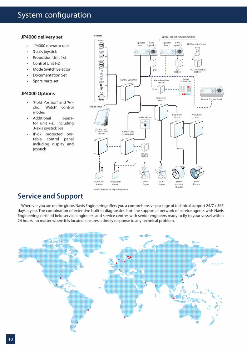
Service and SupportWherever you are on the globe, Navis Engineering offers you a comprehensive package of technical support 24/7 x 365
days a year. The combination of extensive built-in diagnostics, hot-line support, a network of service agents with Navis Engineeringcertifiedfieldserviceengineers,andservicecentreswithseniorengineersreadytoflytoyourvesselwithin24 hours, no matter where it is located, ensures a timely response to any technical problem.
System configuration
JP4000 delivery set
• JP4000operatorunit• 3-axisjoystick• PropulsionUnit(-s)• ControlUnit(-s)• ModeSwitchSelector• DocumentationSet• Sparepartsset
JP4000 Options
• ‘Hold Position’ and‘An-chor Watch’ control modes
• Additional opera-tor unit (-s), including 3-axis joystick (-s)
• IP-67 protected por-table control panel including display and joystick
Log JCU(option)
Alarm Panel Box(option)
BridgeAlarm Panel
Options (Up to 5 network stations)
TSC Box(option)
Control Unit*CU-MPP/MRR
(option)
Remote Portable Panel
FFU Override Box(option)

11
JP4000 Technical Data
Power Supply:
24VDC+30%…-25%АРН4000 power supply is backed up with a +12V battery
Operating and Storage Conditions:
Operating Conditions:Temperature – -25..+75°CHumidity – Up to 95% at 25°C Up to 75% at 45° C Storage Conditions:Temperature – -30..+75°CHumidity – Up to 98% at 25°C Up to 75% at 45° C
Sensor Input & Output
Input:HeadingGyro compass or SAT compass $--HDT, $--THS (10Hz in-put is required)
Position and SpeedDGPS or SAT compass $--GGA, $--VTG(High position resolution for LAT/LON is recommended) ECDIS/ECS (Track Control mode)TCS Category A. - $--APB, $--BWCTCS Category C. - $--HTC/$--HTD or $--HSC
Wind
$--MWV(R), $--MWV(T), $--MWD, $--VWR For Sailing Yachts in Wind Vane control mode
Output:
$AGHTD, $AGRSA, $AGHDT
Input and Output data communicates via standard serial protocol (RS422/RS232).
Display characteristics:
• Technology–WideVGA• Pixelresolution–800*480• Activedisplayarea–143.4(H)x79.2(V)mm• Contrastratio–400:1• Viewingangle(typical)75deg(left/right)and70deg.
(up/down)• Backlighting–adjustable
Operator Unit Technical Data:
• Dimensions288*288*54(withoutknobandrearcon-nectors) mm
• PowerSupplyVoltage–24V+30%...-25%,(APH4000is backed up with +12 V Battery)
• Electrical isolation– Isolation fromcomputing coreand external ports.
• IsolationVoltage:1000V• Data Exchange Interfaces CAN 2.0B, transmission
rate up to 500kb/sec• Acousticalarmnot less than75dB (A)pressureata
distance of 1 meter. • Protectionlevel:IP67ontop,IP22rearside.

Headoffice
Navis Engineering OyTuupakantie 3A, FI 01740
Vantaa, FinlandTel:+358 9 250 9011
Fax:+358 9 250 9012e-mail: [email protected]
http://www.navisincontrol.com
R&D Center
Navis Ltd.Detskaya str., 5a, 199106Saint-Petersburg, Russia
Tel:+7 812 322 67 15Fax: +7 812 322 67 35
e-mail: [email protected]://www.navis.spb.ru
China Office
Navis ChinaShibei Hi-Tech parkJiangChang three road,building 78,room 603.ShangHai 200436,ChinaTel: +86 21 36355718Fax: +86 21 36355728Contact person: James Lie-mail: [email protected] : +86 13501777440