j.ph.piel (phd) application lab manager sopralab
TRANSCRIPT

EPFL October 7th 2008 1
Introduction to ellipsometry
J.Ph.PIEL (PhD)Application Lab ManagerSOPRALAB
EPFL October 7th 2008 2
OUTLINE :
- Basic Theory
- GES5 description
- Data Analysis
- Conclusion

EPFL October 7th 2008 3
I - BASIC THEORY
- Brief history of Ellipsometry
- Principle
- Physical meaning of ψ and Δ

EPFL October 7th 2008 4
Phase measurement
For the 1st time Paul DRUDE use ellipsometry in 1888
2000
EPFL October 7th 2008 5
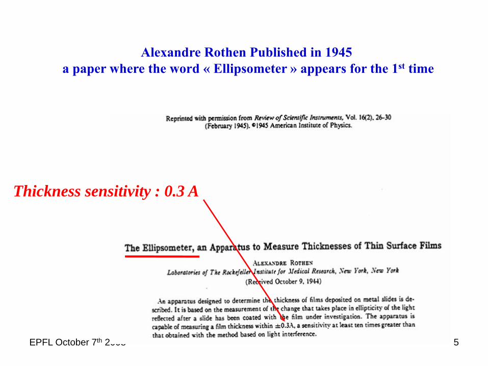
Alexandre Rothen Published in 1945a paper where the word « Ellipsometer » appears for the 1st time
Thickness sensitivity : 0.3 A

EPFL October 7th 2008 6
Bref Historique
Schematic representation of the mounting from Alexandre Rothen (Rev. of scientifique instruments Feb 1945)
EPFL October 7th 2008 7
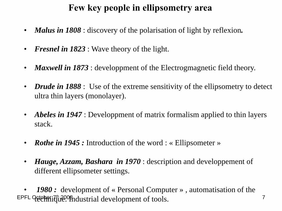
• Malus in 1808 : discovery of the polarisation of light by reflexion.
• Fresnel in 1823 : Wave theory of the light.
• Maxwell in 1873 : developpment of the Electrogmagnetic field theory.
• Drude in 1888 : Use of the extreme sensitivity of the ellipsometry to detect ultra thin layers (monolayer).
• Abeles in 1947 : Developpment of matrix formalism applied to thin layers stack.
• Rothe in 1945 : Introduction of the word : « Ellipsometer »
• Hauge, Azzam, Bashara in 1970 : description and developpement of different ellipsometer settings.
• 1980 : development of « Personal Computer » , automatisation of the technique. Industrial development of tools.
Few key people in ellipsometry area

EPFL October 7th 2008 8
INTRODUCTION
ELLIPSOMETRY is a method based on measurement of the change of thepolarisation state of light after reflection at non normal incidence on thesurface to study
-The measurement gives two independent angles: ψ and Δ
- It is an absolute measurement: do not need any reference- It is a non-direct technique: does not give directly the physicalparameters of the sample (thickness and index)- It is necessary to always use a model to describe the sample
SPECTROSCOPIC ELLIPSOMETRY (SE) gives more comprehensive results since it studies material on a wide spectral range
EPFL October 7th 2008 9
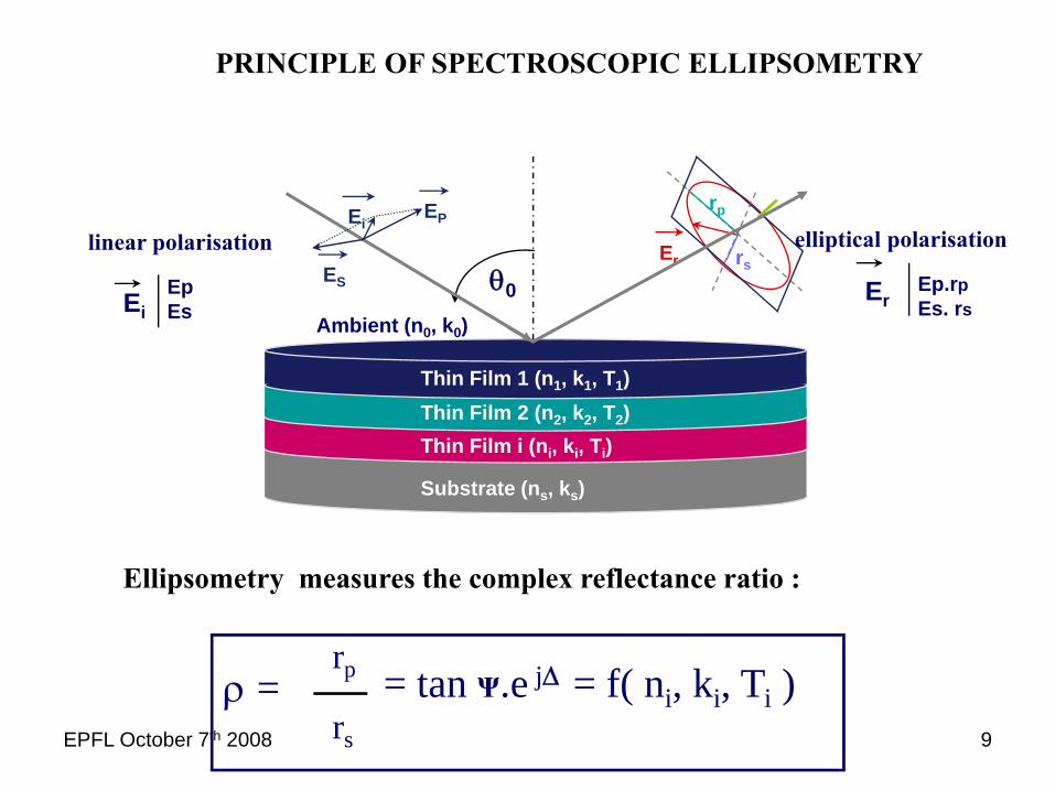
PRINCIPLE OF SPECTROSCOPIC ELLIPSOMETRY
ρ =rp
rs
= tan Ψ.e jΔ = f( ni, ki, Ti )
Substrate (ns, ks)
Thin Film 1 (n1, k1, T1)Thin Film 2 (n2, k2, T2)Thin Film i (ni, ki, Ti)
Ambient (n0, k0)
ES
EiEP
rs
rp
Erlinear polarisation
EiEpEs
ErEp.rpEs. rs
elliptical polarisation
θ0
Ellipsometry measures the complex reflectance ratio :

EPFL October 7th 2008 10
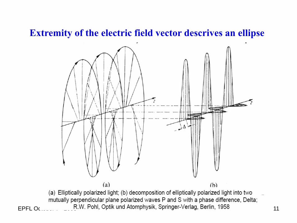
- After reflection on the sample, the extremity of the electric field vector describes an ellipse
εθ
0
rp
rs
p
s
- This ellipse is characterised by
*the ellipticity Tan ε which is the ratio of the large axis to the small axis
*the angle of rotation θ between the main axis and the P axis:
Ψ
EPFL October 7th 2008 11
Extremity of the electric field vector descrives an ellipse
EPFL October 7th 2008 12
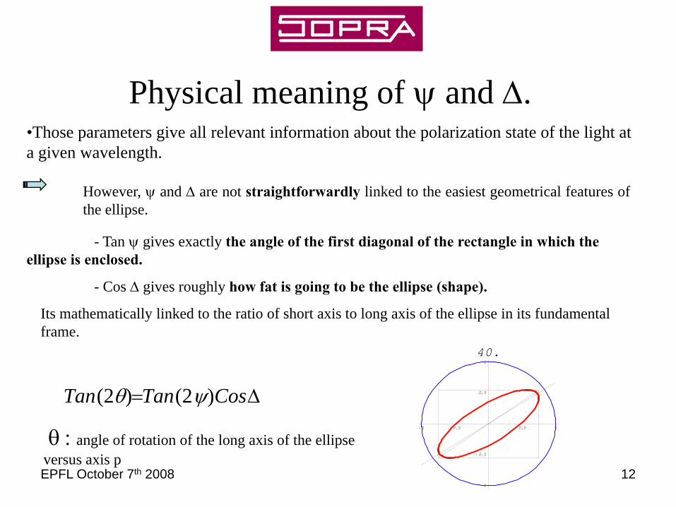
Physical meaning of ψ and Δ.•Those parameters give all relevant information about the polarization state of the light at a given wavelength.
- Tan ψ gives exactly the angle of the first diagonal of the rectangle in which the ellipse is enclosed.
- Cos Δ gives roughly how fat is going to be the ellipse (shape).
Its mathematically linked to the ratio of short axis to long axis of the ellipse in its fundamental frame.
However, ψ and Δ are not straightforwardly linked to the easiest geometrical features ofthe ellipse.
θ : angle of rotation of the long axis of the ellipse versus axis p
Δ= CosTanTan )2()2( ψθ- 1 - 0.5 0.5 1
- 1
- 0.5
0.5
1
40.

EPFL October 7th 2008 13
- 1 - 0.5 0.5 1
- 1
- 0.5
0.5
1
0
- 1 - 0.5 0.5 1
- 1
- 0.5
0.5
1
20.
- 1 - 0.5 0.5 1
- 1
- 0.5
0.5
1
40.
- 1 - 0.5 0.5 1
- 1
- 0.5
0.5
1
60.
- 1 - 0.5 0.5 1
- 1
- 0.5
0.5
1
80.
- 1 - 0.5 0.5 1
- 1
- 0.5
0.5
1
90.
• Example of some different phase shift (Δ) for a given ψ value.• On those graphics, the long axis is the ellipse is represented and it has to be compared with the
diagonal of the rectangle.• Because ψ is fixed, the ellipse is enclosed in the same rectangle for each graphic.• Modification of Δ change both angle of inclination and ellipticity.
EPFL October 7th 2008 14
II - GES5 DESCRIPTION
- Physical description
- Jones Formalism
- Mathematical treatment of the signal
- Example

EPFL October 7th 2008 15
Goniometer
Analyser Arm
Polariser Arm
Sample
Mapping rho/theta
Microspots

EPFL October 7th 2008 16

EPFL October 7th 2008 17

EPFL October 7th 2008 18
SPECTROSCOPIC ELLIPSOMETER
Scanninigchannel
C.C.D.channel
Xe LampPA
Optical Fiber
Goniometer
Photo Multiplier
Tube
EPFL October 7th 2008 19
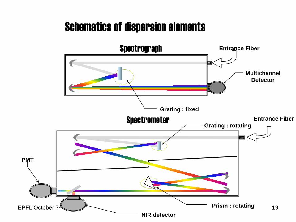
Spectrometer
Spectrograph
Schematics of dispersion elements
Grating : rotating
Prism : rotatingNIR detector
PMT
Entrance FiberGrating : fixed
MultichannelDetector
Entrance Fiber
EPFL October 7th 2008 20
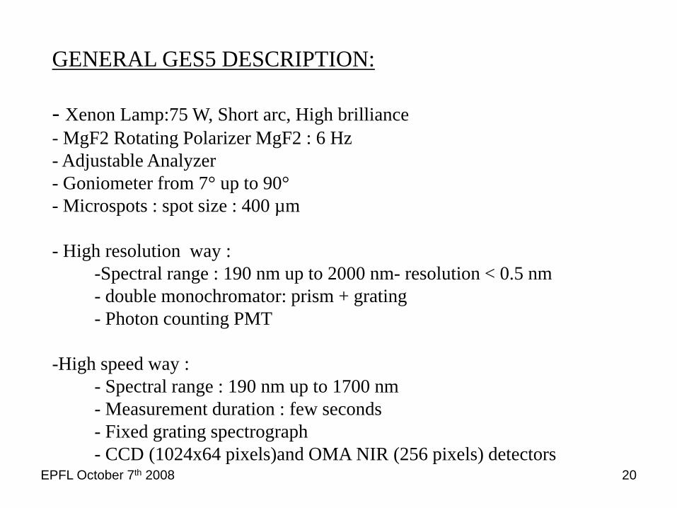
GENERAL GES5 DESCRIPTION:
- Xenon Lamp:75 W, Short arc, High brilliance- MgF2 Rotating Polarizer MgF2 : 6 Hz - Adjustable Analyzer- Goniometer from 7° up to 90°- Microspots : spot size : 400 µm
- High resolution way :-Spectral range : 190 nm up to 2000 nm- resolution < 0.5 nm- double monochromator: prism + grating- Photon counting PMT
-High speed way : - Spectral range : 190 nm up to 1700 nm- Measurement duration : few seconds- Fixed grating spectrograph- CCD (1024x64 pixels)and OMA NIR (256 pixels) detectors
EPFL October 7th 2008 21
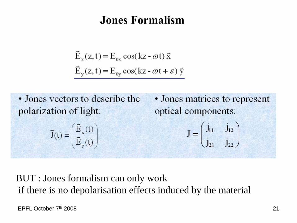
Jones Formalism
BUT : Jones formalism can only workif there is no depolarisation effects induced by the material

EPFL October 7th 2008 22
Optical system with no depolarisation effects is characterized by this following Jones Matrix :
2X2 complex Matrix

EPFL October 7th 2008 23
If the material is isotrope :
Ellipsometric Angles Ψ and Δ measured simultaneously
EPFL October 7th 2008 24
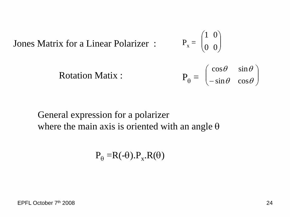
Pθ =R(-θ).Px.R(θ)
Jones Matrix for a Linear Polarizer : Px = ⎟⎟⎠
⎞⎜⎜⎝
⎛0001
Pθ = ⎟⎟⎠
⎞⎜⎜⎝
⎛− θθ
θθcossinsincos
Rotation Matix :
General expression for a polarizer where the main axis is oriented with an angle θ

EPFL October 7th 2008 25
I = Edp . Edp* + Eds . Eds
*
I (t) = I0 . ( 1 + α Cos 2 ω(t) + β Sin 2 ω(t) )A : Angle between Analyser and plane of Incidence.ω(t) : Angle between Polariseur and plane of Incidence.
EPFL October 7th 2008 26
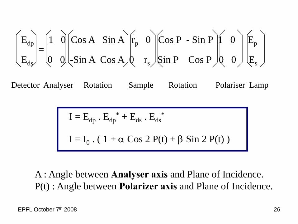
Edp 1 0 Cos A Sin A rp 0 Cos P - Sin P 1 0 Ep
Eds 0 0 -Sin A Cos A 0 rs Sin P Cos P 0 0 Es
=
Detector Analyser Rotation Sample Rotation Polariser Lamp
A : Angle between Analyser axis and Plane of Incidence.P(t) : Angle between Polarizer axis and Plane of Incidence.
I = Edp . Edp* + Eds . Eds
*
I = I0 . ( 1 + α Cos 2 P(t) + β Sin 2 P(t) )

EPFL October 7th 2008 27
S1 S4S2 S3 S1
Time
Intensity
S I P dP10
4
= ∫ ( )π
S I P dP24
2
= ∫ ( )π
π
S I P dP32
34
= ∫ ( )π
π
S I P dP43
4
= ∫ ( )π
π
[S1 - S2 -S3 + S4 ]2 I0
α =[S1 + S2 - S3 - S4 ]
2 I0β =
[S1 + S2 + S3 + S4 ]Π
Ι0 =
HADAMART TRANSFORM

EPFL October 7th 2008 28
CALCULATION OF THE ELLIPSOMETRIC PARAMETERS
Cos 2 ATan 2 Ψ + Tan 2 A
Ι0 =
Tan 2 Ψ - Tan 2 ATan 2 Ψ + Tan 2 A
α = 2 Cos Δ . Tan Ψ. Tan ATan 2 Ψ + Tan 2 A
β =
1 + α 1 - α
Tan Ψ = Tan A .
β1 - α2
Cos Δ =
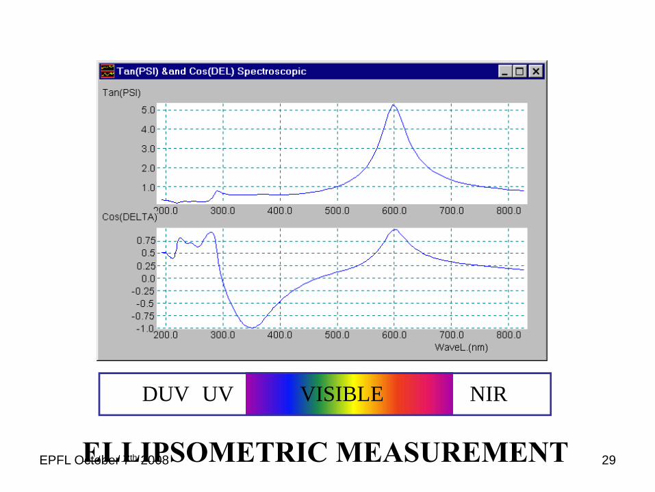
EPFL October 7th 2008 29
DUV UV VISIBLE NIR
ELLIPSOMETRIC MEASUREMENT

EPFL October 7th 2008 30
RESULTS ANALYSIS
Ti , ni , ki
Experimental Measurement=
Model Simulation ?
No
Yes
CosΔ
TanΨ
ExperimentalMeasurement
Physical ModelEstimated sample structure
- Film Stack and structure- Material n, k, dispersion- Composition Fraction of Mixture
REAL SAMPLE STRUCTURE
Non direct technique.
Need the use of modelsto interpret the measurements and to get physical parameters of the layers

EPFL October 7th 2008 31
III - DATA ANALYSIS
- Which physical parameters can we get ?
- Sensisitivy of the technique
- Description of the main models used
- How to describe optical properties of the materials.
EPFL October 7th 2008 32
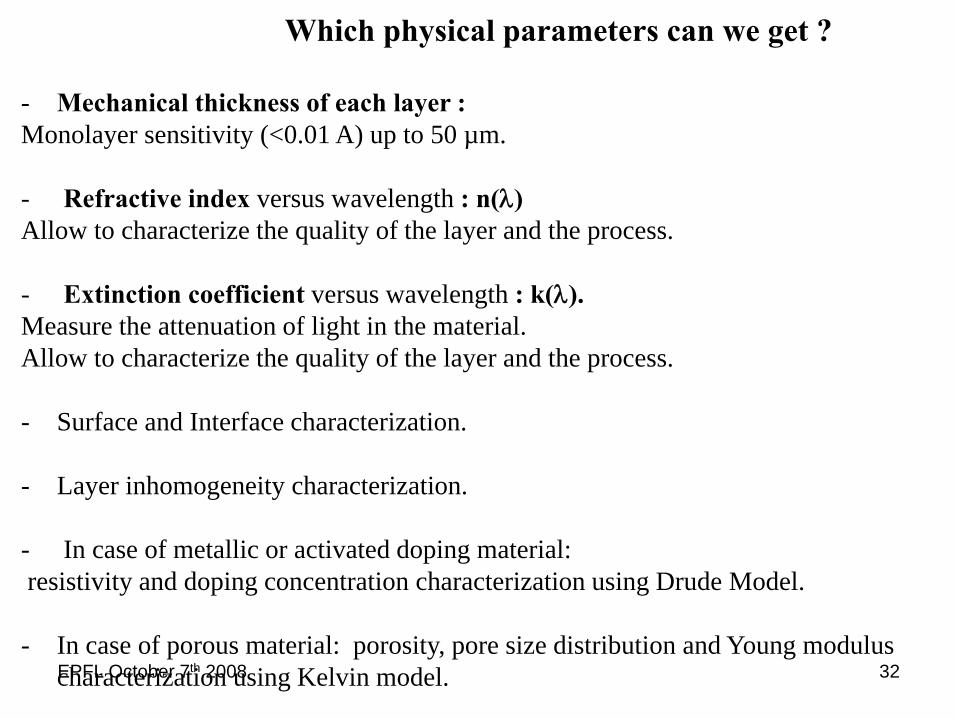
- Mechanical thickness of each layer :Monolayer sensitivity (<0.01 A) up to 50 µm.
- Refractive index versus wavelength : n(λ)Allow to characterize the quality of the layer and the process.
- Extinction coefficient versus wavelength : k(λ).Measure the attenuation of light in the material.Allow to characterize the quality of the layer and the process.
- Surface and Interface characterization.
- Layer inhomogeneity characterization.
- In case of metallic or activated doping material:resistivity and doping concentration characterization using Drude Model.
- In case of porous material: porosity, pore size distribution and Young modulus characterization using Kelvin model.
Which physical parameters can we get ?

EPFL October 7th 2008 33
Spectroscopic ellipsometry sensitiviy
Phase variation : Δ is extremelly sensitive to ultra thin layers
Angle of incidence: 75°

EPFL October 7th 2008 34
0nm
10 A
Spectroscopic ellipsometry sensitiviy
Angle of incidence: 75°
Sensitivity could reach 0.01 Aor 1 picometer

EPFL October 7th 2008 35
Description of the main models used
EPFL October 7th 2008 36
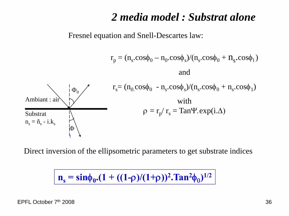
2 media model : Substrat alone
Φ1
Φ0
Ambiant : air
Substratns = ñs - i.ks
rp = (ns.cosφ0 – n0.cosφs)/(ns.cosφ0 + ns.cosφ1)
and
rs= (n0.cosφ0 - ns.cosφs)/(ns.cosφ0 + ns.cosφ1)
withρ = rp/ rs = TanΨ.exp(i.Δ)
Fresnel equation and Snell-Descartes law:
ns = sinφ0.(1 + ((1-ρ)/(1+ρ))2.Tan2φ0)1/2
Direct inversion of the ellipsometric parameters to get substrate indices

EPFL October 7th 2008 37Silicium Angle of incidence 75°
2 media model : Substrat alone

EPFL October 7th 2008 38
3 media model : one layer on known substrate

EPFL October 7th 2008 39
Native oxide (SiO2) on SiliconSicr
SiO2 30.8 Å
3 media model : one layer on known substrate
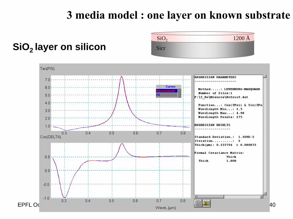
EPFL October 7th 2008 40
Sicr
SiO2 1200 Å
SiO2 layer on silicon
3 media model : one layer on known substrate
EPFL October 7th 2008 41
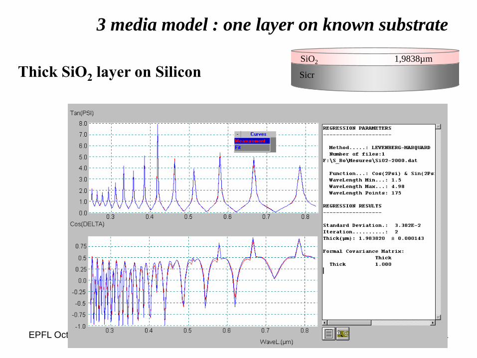
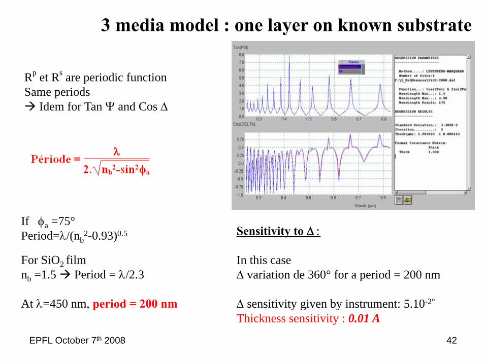
3 media model : one layer on known substrate
Thick SiO2 layer on Silicon Sicr
SiO2 1,9838µm
EPFL October 7th 2008 42
Rp et Rs are periodic function Same periods
Idem for Tan Ψ and Cos Δ
If φa =75°Period=λ/(nb
2-0.93)0.5
For SiO2 filmnb =1.5 Period = λ/2.3
At λ=450 nm, period = 200 nm
Sensitivity to Δ :
In this caseΔ variation de 360° for a period = 200 nm
Δ sensitivity given by instrument: 5.10-2°
Thickness sensitivity : 0.01 A
3 media model : one layer on known substrate
EPFL October 7th 2008 43
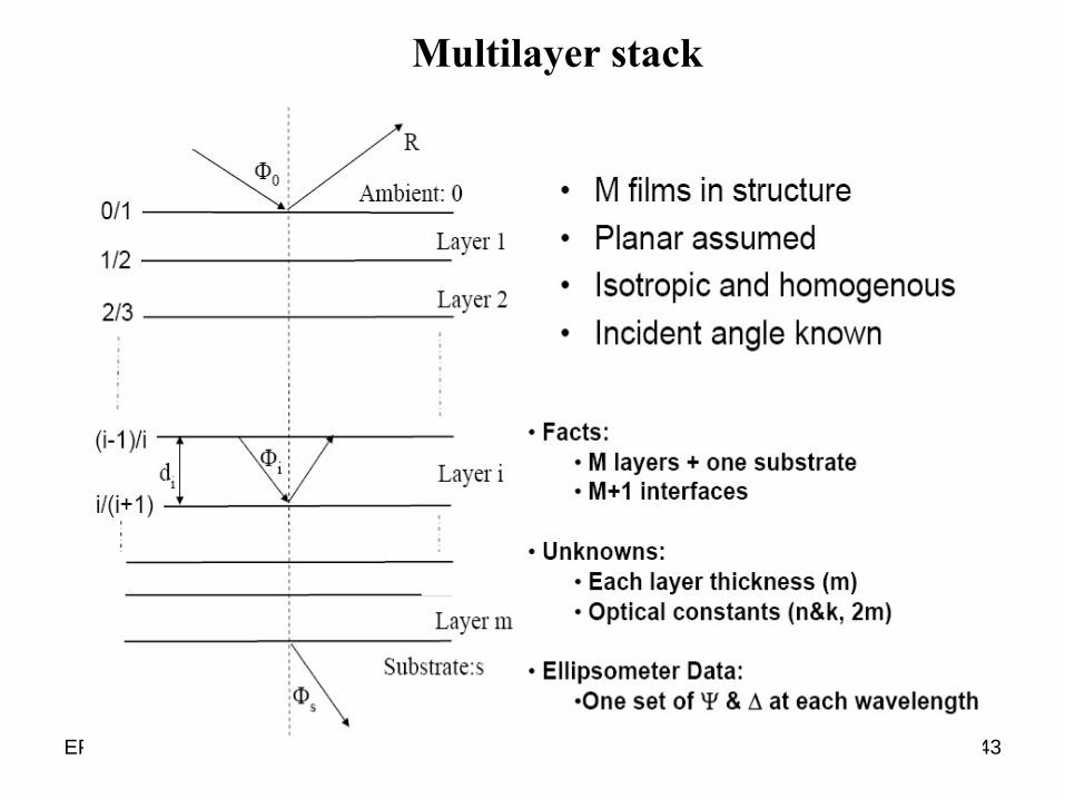
Multilayer stack
EPFL October 7th 2008 44
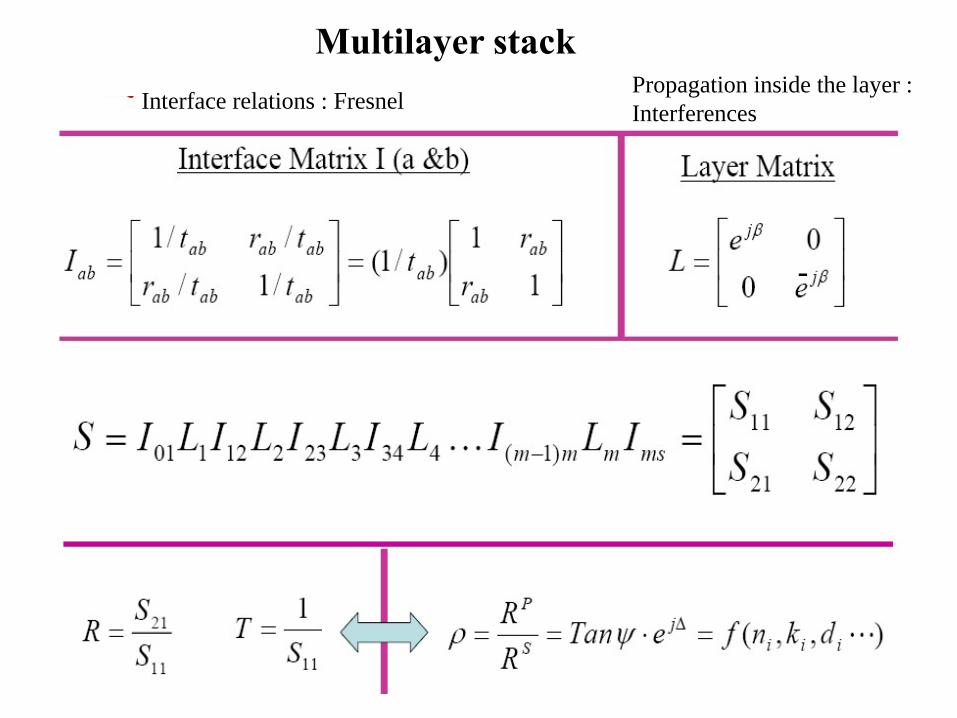
Interface relations : FresnelPropagation inside the layer :Interferences
-
Multilayer stack

EPFL October 7th 2008 45
How to describe optical properties of the materials
• Index library• Effective medium mixing laws• Dispersion law• Harmonic oscillators laws• Drude laws
EPFL October 7th 2008 46
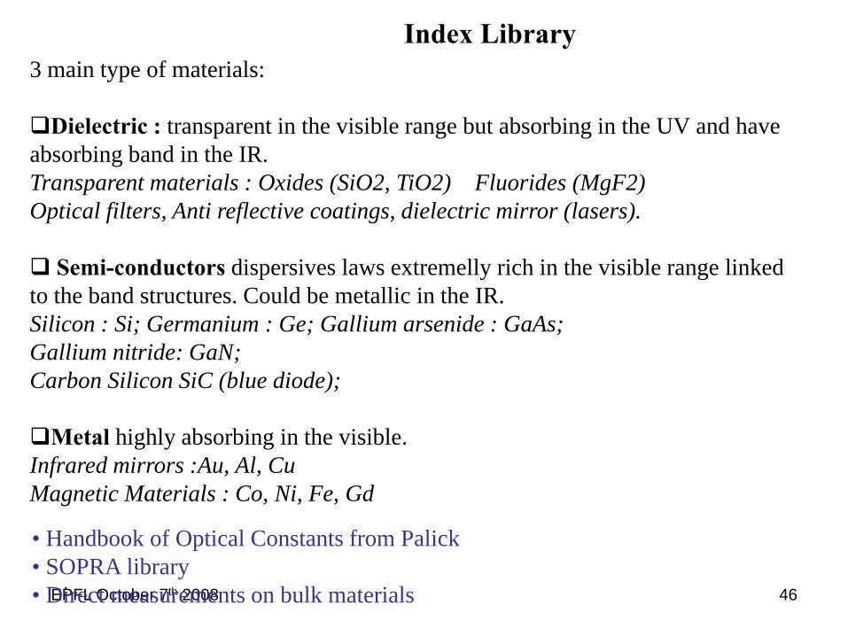
Index Library3 main type of materials:
Dielectric : transparent in the visible range but absorbing in the UV and have absorbing band in the IR.Transparent materials : Oxides (SiO2, TiO2) Fluorides (MgF2)Optical filters, Anti reflective coatings, dielectric mirror (lasers).
Semi-conductors dispersives laws extremelly rich in the visible range linked to the band structures. Could be metallic in the IR.Silicon : Si; Germanium : Ge; Gallium arsenide : GaAs;Gallium nitride: GaN;Carbon Silicon SiC (blue diode);
Metal highly absorbing in the visible. Infrared mirrors :Au, Al, CuMagnetic Materials : Co, Ni, Fe, Gd
• Handbook of Optical Constants from Palick• SOPRA library• Direct measurements on bulk materials
EPFL October 7th 2008 47
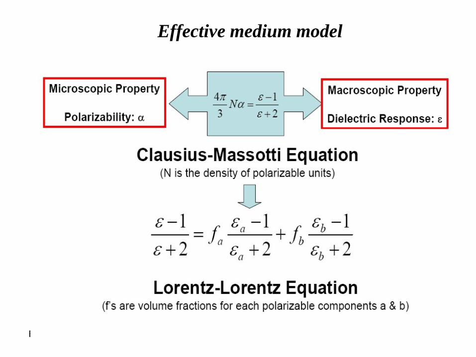
Effective medium model

EPFL October 7th 2008 48
Popular effective medium model
EPFL October 7th 2008 49
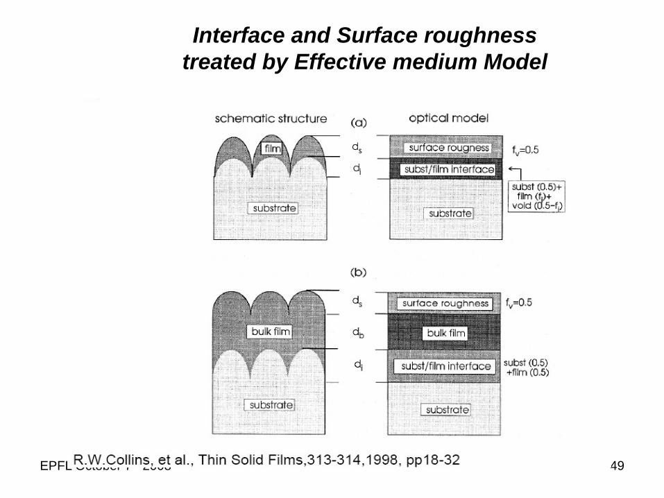
Interface and Surface roughnesstreated by Effective medium Model

EPFL October 7th 2008 50
- Model is convenient for physical or mechanical mixing.Ex : Porous material with inclusion of void.
- Model is not convenient for chemical mixingEx : Inclusion of atom in elementary cellsor variable atomic concentration Ex : Si(1-x)Gex.
- Model is not applicable when the size of inhomogeneitiesexceed few hundredth (1/100) of the wavelenght of the beam.
Limits of the effective medium model
EPFL October 7th 2008 51
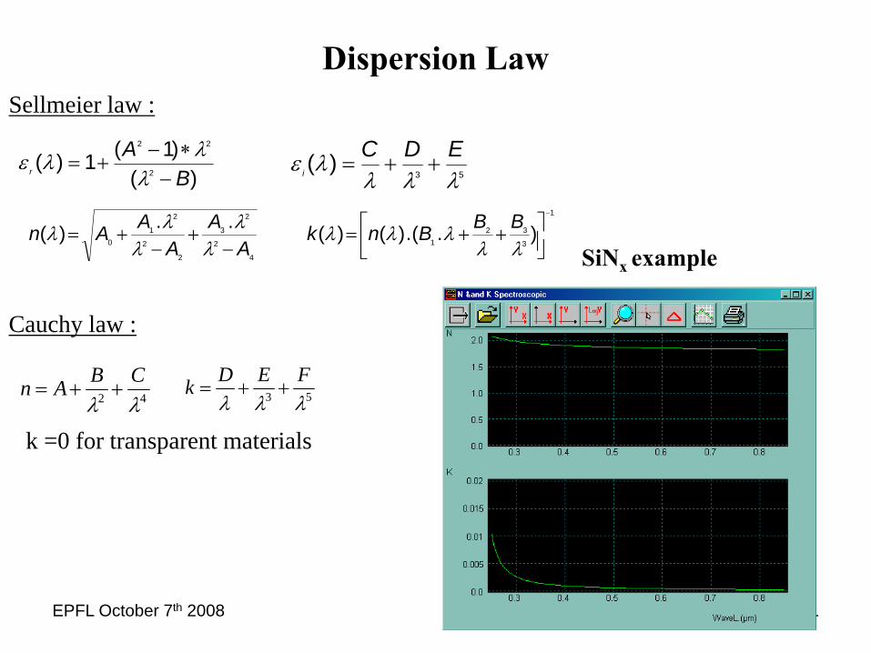
Dispersion LawSellmeier law :
42 λλCBAn ++= 53 λλλ
FEDk ++=
Cauchy law :
k =0 for transparent materials
)()1(1)(
2
22
BA
r −∗−
+=λ
λλε53
)(λλλ
λε EDCi ++=
1
3
321
4
2
2
3
2
2
2
10 ).(.)()(..)(
−
⎥⎦⎤
⎢⎣⎡ ++=
−+
−+=
λλλλλ
λλ
λλλ BBBnk
AA
AAAn
SiNx example
EPFL October 7th 2008 52
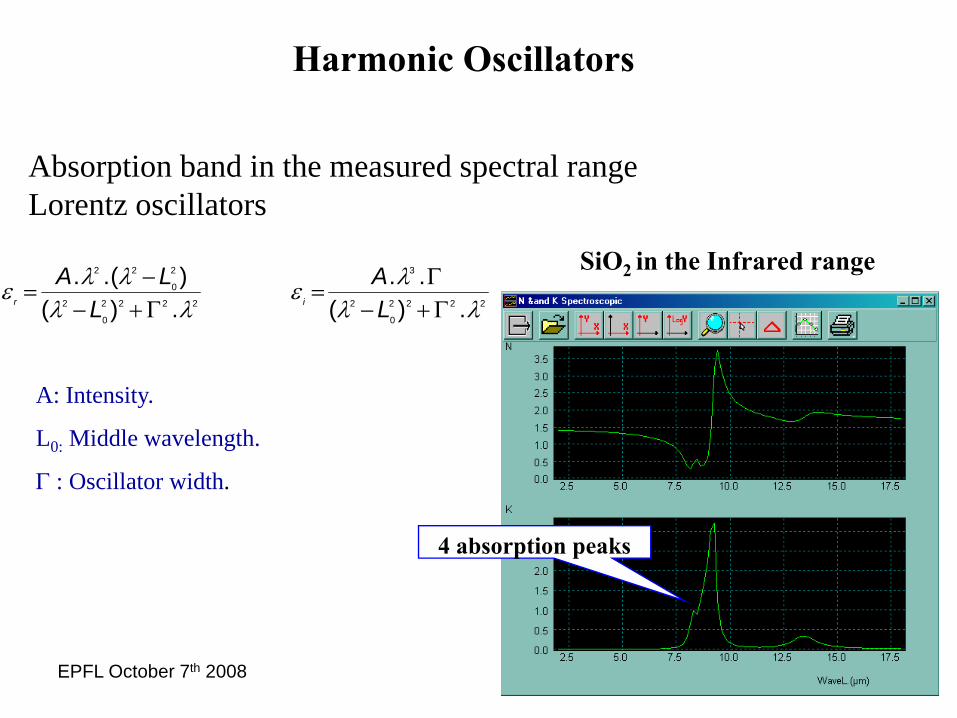
4 absorption peaks
SiO2 in the Infrared range2222
0
2
3
2222
0
2
2
0
22
.)(..
.)()(..
λλλε
λλλλε
Γ+−Γ
=Γ+−−
=LA
LLA
ir
Harmonic Oscillators
Absorption band in the measured spectral rangeLorentz oscillators
A: Intensity.
L0: Middle wavelength.
Γ : Oscillator width.

EPFL October 7th 2008 53
100 nm of an absorbing layer on Silicon substrate
Spectroscopic Ellipsometry data Indices of the layer
Harmonic Oscillators
EPFL October 7th 2008 54
Wavelength ( μm)
2 4 6 8 10 12 14 16
n, k
0.0
0.5
1.0
1.5
2.0
2.5
3.0
3.5
4.0
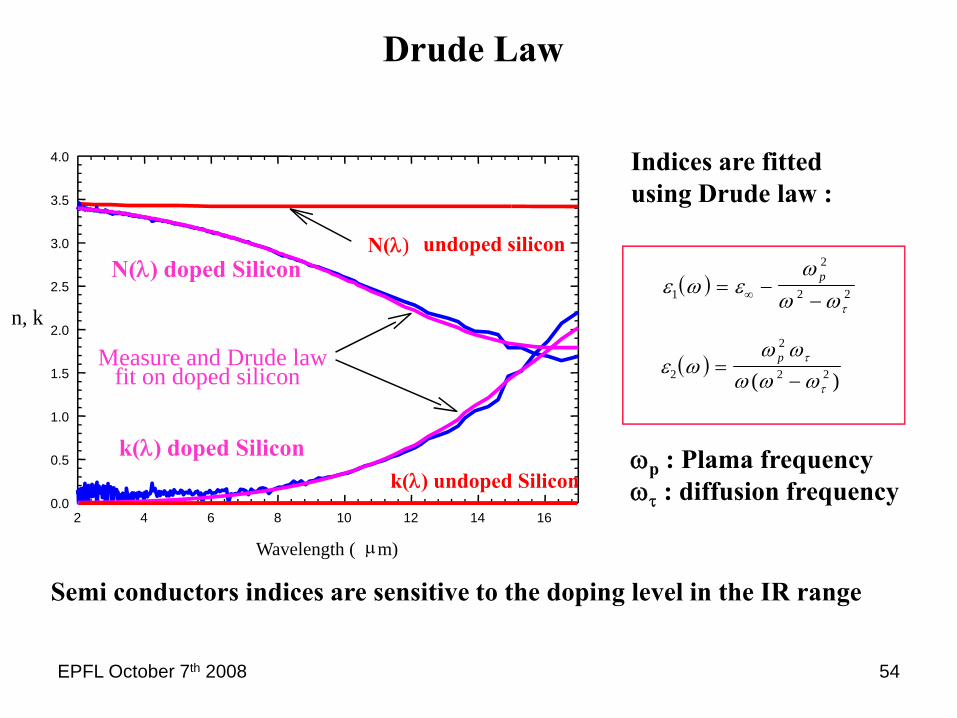
Measure and Drude lawfit on doped silicon
undoped silicon
( )ε ω εω
ω ωτ1
2
2 2= −−∞
p
( )ε ωω ω
ω ω ωτ
τ2
2
2 2=−
p
( )
Indices are fitted using Drude law :
ωp : Plama frequencyωτ : diffusion frequency
Semi conductors indices are sensitive to the doping level in the IR range
Drude Law
N(λ) doped SiliconN(λ)
k(λ) doped Siliconk(λ) undoped Silicon
EPFL October 7th 2008 55
μωτ
=e
m*
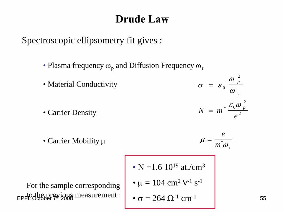
Spectroscopic ellipsometry fit gives :
• Plasma frequency ωp and Diffusion Frequency ωτ
• Material Conductivity
• Carrier Density
• Carrier Mobility μ
σ εωω τ
= 0
2p
N me
p= * ε ω02
2
For the sample corresponding to the previous measurement :
• N =1.6 1019 at./cm3
• μ = 104 cm2 V-1 s-1
• σ = 264 Ω-1 cm-1
Drude Law
EPFL October 7th 2008 56
Conclusion

EPFL October 7th 2008 57
The measurement gives two independent angles: ψ and Δ
- Absolute measurement: do not need any reference.- Extremely sensitive to very thin layers (less than a monolayer).- fast : get the full spectrum (190 nm up 1700 nm) in few seconds
- Non-direct technique: does not give directly the physicalparameters of the sample (thickness and index)- Need to use a model to describe the sample.
Determination of : but also :Thickness PorosityRefractive index : n ResistivityExtinction coefficient : k Molecular bounds