(jr) - defense technical information centerdtic.mil/dtic/tr/fulltext/u2/a950343.pdf · (jr)...
TRANSCRIPT

WATERTOWN4A8N'rM1
(jr) WATERTOWN 72, MASS.
SWATERTOWN' ARSENAL-LABORATORIES
-SUBSIZE, CHARPY CORRELAtION WITH, STANDARD 'CHARPY,
TECHNCAL EPORT NO. WAL TR 112/95
BY,
;CHARLES: 9. -COLL
DECEMBER J1959
0.0.. PROJECTs! INDUSTRIAL PREPAREDNE'SS, E E T
NEASUR -'- DEVELOFIENT OFSUB3 IZE -CNARPYVSANDARD MAY 8 1981
1This document 'b*~n'u
-dt ub16nii reflixs nd f .V
W4 ATETOWNASEAWvTEROWN 729 , MASS.,

AD Impact testsCharpy, subsize
/41
Technica 5, o. WAL-TR--112/95
/ By
ICharle~s HI. urli
Decombwr 1#59
0.0. Project: Industrial Preparedness MeasureDevelopment of Subsize Charpy Standard
P.E.S.D. No.: 70304231-15-42606
j ~ ~Agn Ailing li en M 12, ,Iýnle.
I ~WATER?)WIN ARSENAL* VWATERT~OWN-7 2, MASS.
WATERTOWN ARSENAL LABORATORIES
TITLE
SUBSIZE CIIARPY CORRELATION WITH STANDARD CHARPY
ABSTRACT
To provide a means of impact acceptance testing of specimens whichmust be obtained from thin or small diameter sections, a study was made,using various specimen sizes, of the Charpy V notch impact properties ofsteels over a range of temperatures encompassing transitions from ductileto brittle behavior.
The test data tend to verify a previously established nonlinear cor-relation between selected subsizes above the transition range and furtherindicate a linear correlation between the energy required to fracturestandard-size end subsize V notch Charpy specimens at the normal acceptancetesting temperature of -40°C.
Further engineering data, needed to incorporate requirements in aspecification, are currently being obtained.
CHARLES H. CURLLGeneral Engineer
APPROVED:
SF.- SULLIVAN " REPOR. APPROVED'•lirector •Dt -,I•
atertown Arsenal Laboratories Datek
j.,O--- , -On WAL Board of Review
~IMS GRA&I [ChAL magW14*p'IC- TA13
nu-and/or
a f¢t
........ l m I in

INTRODUCTION
With the advent of thin-walled cylinders for rockets and tubes, it hasbecome necessary to provide a means of impact testing materials from suchsections for Ordnance acceptance purposes. Because it is not possible toobtain standard-size Charpy impact specimens from thin sections, a correls-Lion between the energies to fracture standard a,.4 subsize Charpy V notchimpact specimens needs to be established. It is the purpose of this reportto develop a correlation between selected subsize and standard-size CharpyV notch impact specimens.
A previous investigation on size relationships in the impact test byCurll and Orner' developed a nonlinear correlation based upon data takenfrom above the transition zone. The current investigation tends to verifythe previous relationship obtained.
This report describes the materials used, the experimental work done,and illustrates the graphs developed. It further develops an analyticalcorrelation (using a reference to the Law of Similitude by Sachs 1 and thereduction of deformation) between the energy to frac';ure the standard andaubsize Charpy V notch impact specimens.
MATERIALS
The following materials were used in this investigation:
1. AISI-2340 Modified Steel 4. AISI-4140 Steel
2. AISI-3140 Modified Steel 5. Class 90 Steel
3. AISI-4042 Modified Steel 6. Nickel Steel
CHEMICAL ANALYSES (M by Weight)
No. Material C Mn SI S P Ni Cr No V Cu
1 2340 .43 .78 .24 - 1 78 .07 Trace
2 3140 .44 1.11 .21 - 2.56 .96 Trace
3 4042 .44 .73 .19 - - Trace .03 .33
4 4140 .38- .40- .20- .04 .04 .80- .15-.43 .60 .35 1.10 .25
5 Class 90 .17 .33 .23 .03 .04 2.13 .97 .22 .03 .057
6 Ni Steel .14 .50 .23 .04 .017 3.30
10fg: 1. Dash seans analysis not made.2. Chemical analyses for materials in Pfgures 9, 3, and E say be found
in Reference J.
The three steels designated "modifiedw were made in thirty-pound ingotsin the Watertown Arsenal Laboratories melt laboratory. The modificationswere made on the Ni, Cr, and Mo Contents.
-3-
Preceding Page Blank

The AISI-4'40 steel was received as 5/8-inch-square rod. The class 90steel was received as 5/8-inch-thick plate. The data on the nickel steelwere obtained from a different investigation.8 The three modified steelswere obtainod as ingots and homogenized at 2150°F for four hours. TheAISI-3140 was air-cooled and normalized at 1600OF for four hours while theAISI-2340 and 4042 were furnace-cooled and homogenized at 1650'F for fourhours to permit easier removal of the riser. The as-cast billets were hot-worked at 2000'F to the following schedule:
1. Heated for two hours.
2. Forged on 200-ton press to •-5/8-inch-square bar in two reductions.
3. Hot rolled to 1/2" x 2-3/4" bar stock in two reductions.
4. Air cooled.
The materials received the following heat treatments:
1. AISI-2340
Nomlz 60F 2 hrs. Air CoolIReheat 1475OF 2 hrs. Agitated Oil QuenchDraw 1200OF 2 hrs. Oil Quench
2. AISI- 3140
Normalize 1600°F 2 hrs. Air CoolIReheat 1525°F 2 hrs. Agitated Oil QuenchDraw 1100°F 2 hbrI. Oil QuenchRedraw 12000 F 2 hrs. Oil Quench
3. AISI-4042
Normalize 1600°F 2 hrs. Air CoolReheat 1550°F 2 hrs. Agitated Oil QuenchDraw 1000OF 2 hrs. Oil Quench
4. AISI-4140
Normalize j 1600°F 1 hr. Air CoolReheat 15500 F -hr. Oil QuenchDraw J 1000°F % hr. Oil Quench
The class 90steel was used in the as-received -condition (quenched andtempered), but the heat treat was not available. The-materials had thefollowinj Rockwell hardness:
-4-

U ~ , iIiUui i J•, Ie I t 11 111 I I, IIt , u unn m'
BeR Rb
1. AISI- 2340 992.' AISI-3140 26.23. AISI-4042 33.84. AISI-4140 38.35. Class 90 Steel 22.76. Nickel Steel 82
The various specimen sizes (Figure 1) used in this investigation wereselected as a result of the previous report by the author (Reference 1) withadditional sizes to verify the theory presented in this report.- The speci-mens of AISI-4140 were longitudinal and all others were transverse. Thenickel steel data obtained from another investigation (Reference 3) add tothe verification by use of a double-size specimen.
TEST PROCEDURE
V notched Charpy bars in various sizes, ranging from double size toone-quarter size (cross-sectional area measurement)(Figure 1), were testedover a range of temperatures encompassing their transitions from ductile tobrittle behavior. All specimens were braken in a conventional manner on aSonntag impact testing machine (capacity 240 ft-lb; pendulum velocity 16.8it/sec).' Special anvils and shims were provided to maintain the point ofimpact at the center of percussion of the pendulum when nonstandard speci-mena were tested.- For the shorter-length specimens, the anvil span wasshortened to a distance of 0.787" from the normal span of 1.574". There isone exception to the above technique.- The data for-the double-width, half-depth specimen of the nickel steel were obtained from Reference 3.'
TEST RESULTS AND DISCUSSIONS
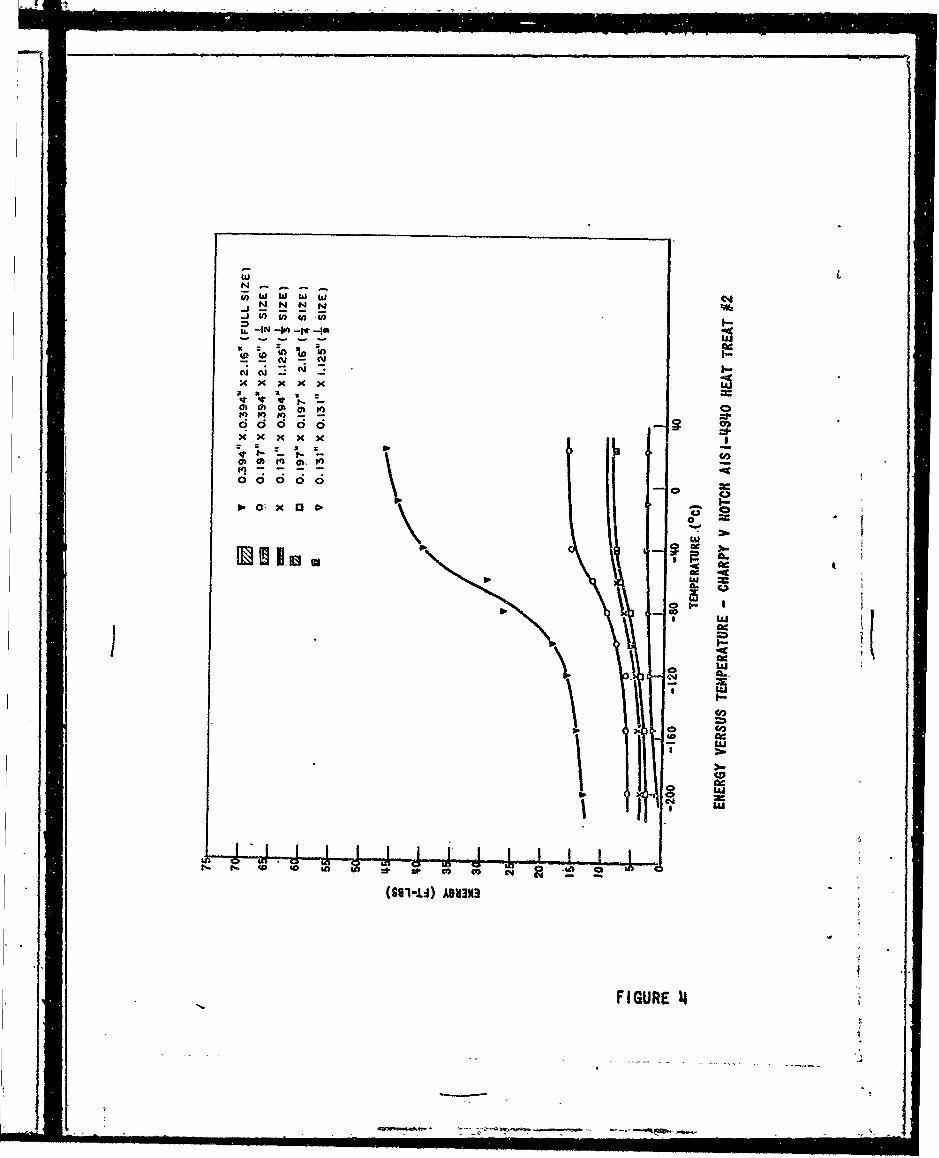
Tables I through VI list testing temperatures, averaged energies absorbed(generally three at each temperature with one to two tests at extremely lowtemperatures), and percentages of fibrosity in the fractured faces.' Theenergy versus temperature data are presented graphically in Figures 2 through10. The graphs of Figures 2, 3, and 4 were taken from a previous report.1-
In order to verify the previously established correlation, the data fromthe curves of Figures 5 through 9 (taken at their respective transition tem-peratures* as indicated in the tables) were plotted on the established cor-relation curves (Figure 11) and gave the following results:
L.' 1/2 Size.
An average error of 0.62 ft-lb with a single maximum error of1.75 ft-lb.ý
Ofas.ition te.e rature. is defined as the lotwst tesperattre at which the s0secsen breakswith a .-1OOS.f 4robs fractswe.
-5 t
2. 1/3 Size:
An average error of 0.52 ft-lb with a single maximum error of1.25 ft-lb.
3. 1/4 Size:
An average error of 0.50 ft-lb with a single maximum error of1.25 ft-lb.
Although these results tend to verify the correlation, the actual useof the relationship is limited to the 100% fibrous zone of the standardsize specimens which has a minimal value as an acceptance test.,
Since the objective was td obtain a correlation using only one param-eter, an investigation was made to explain the phenomena in physical terms.-Figure 12 is a macrophoto of the plastic deformation in a Charpy V notchimpact specimen., The specimen was subjected to a 30 ft-lb blow in impactand then heat-treated to bring out the grain growth due to plastic deforma-tion. The photo shows that a certain amount of energy will be absorbed inthe plastic deformation of a specimen prior to crack initiation and propaga-tion. It is also evident that additional energy will be required to frac-ture the specimen; this energy has .been designated as the rupture energy.-Although this rupture energy is not specifically defined,, it is known thatthis energy will consist of some plastic deformation - especially duringcrack propagation.- That is, as the crack progresses, there will be somedeformation just below the surface both preceding the crack extension andparallel to the crack. This energy is very nearly proportional to the crackarea, while the deformation energy is related to the volume. By using thistheory of total energy for fracture being composed of deformation and rup-ture energy (E. - Ed + Er) coupled with the Law of Similitude,* an explanationof the physical phenomena of the Charpy relationship may be made.- As thespecimen size is reduced, the volume of deformation will be reduced, however,
the deformation reduction is dependent upon the dimension reduced. That is,if the depth dimension is reduced, the volume of deformation will be reducedby the square of the depth dimension; but if the width dimension is reduced,the volume of deformation will be reduced in direct proportion. Further,if the material is so notch sensitive that negligible deformation willresult, then the energies of the specimens will again be directly propor-tional to their sizes.
To verify the foregoing, a mathematic'al approach was made:
Let E, - Total. Energy of Fracture
Er - Energy of -Rupture
Ed - Energy of Deformation
then E, - Er + Ed
of I'M' e t he 0 bc ' c 0re" 'r" erth e
at if",~o~n tut050 'l otht (Ieeec )
-6-

and by Law of Simi1itude:,
For '/2-slze spelth:(Figure 1) E., 1/2 Er + 114 Ed
l/ -13size specimen~s E. - 1/3 Er + 1/9 Ed
S1/4ý.size spedime•r: E 1 1/4 Er + 1/8 Ed
'• Th data (taken at -409%). from the curves of Figures 2, 3, and 4 and
used in the ahye; simul. , eous equations produced a rupture energy (Er) of21.6 ft-lb for ductile materials and a rupture energy-(Er) of 12.0 ft-lbfor brittle materials. The data taken (at -400C) from the curves of Fig-ures 5 through 10 and used in the above simultaneous equations yielded
reasonably satisfactory results.- By plotting the data obtained from theabove curves, a graphical solution may be obtained which is in agreementwith the previous simultaneous solution. The difference in the reductionof the volume of deformation is a measure of the degree of slope change.As would be expected, the brittle materials have a zero slope.
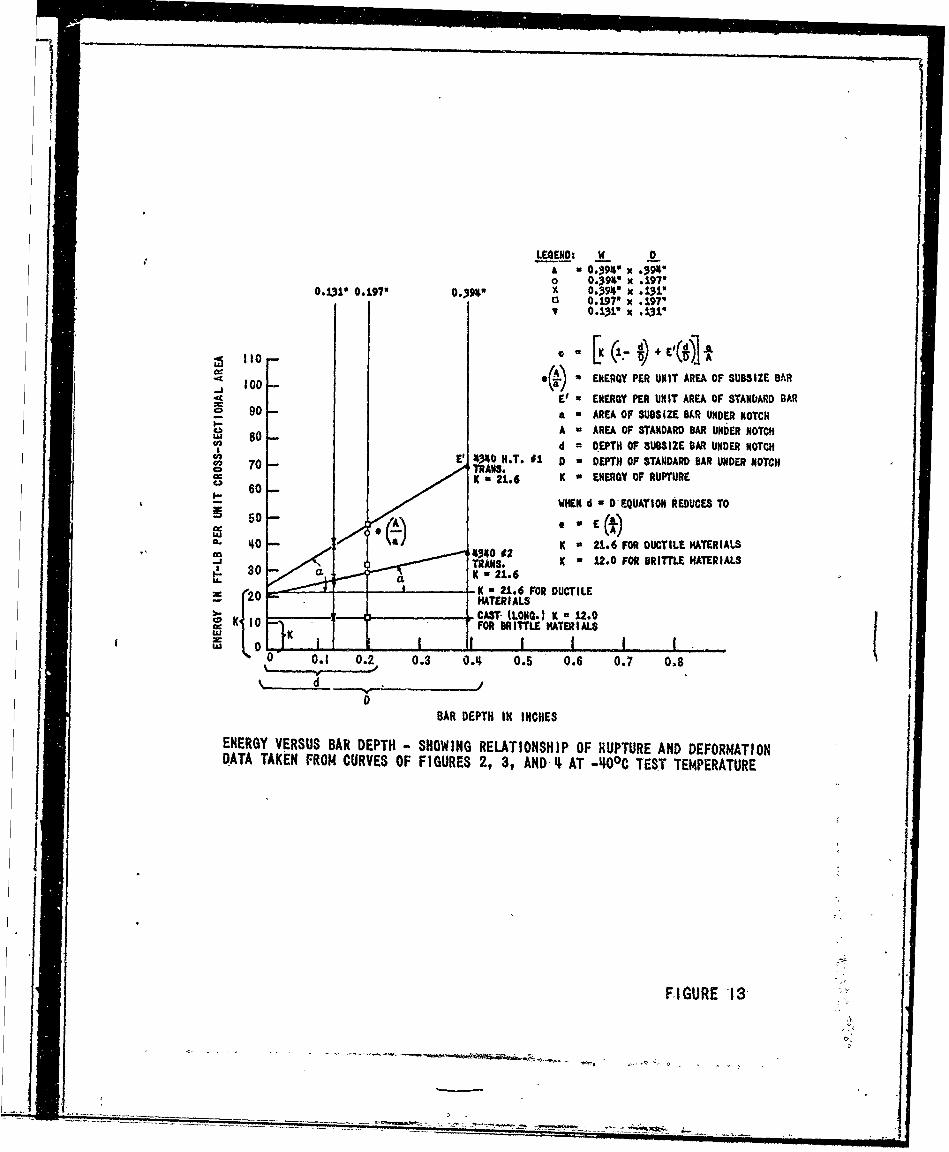
By using the curves in Figure 13, an equation for the solution of theenergy of the subsize specimen may be developed based upon the energy ofrupture (designated by K in Figure 13), the energy of deformation (tangentof the angle equal to the slope), and the specimen dimensions.
V/ - Energy per unit area of full size bar
eA'% Energy per unit area of subsize bara
A.- Cross-sectional area of full size barunder notch
a z Cross-sectional area of subsize barunder notch
D = Depth under notch of full size bar
d = Depth under notch of subsize bar
K - Energy of rupture - Er
Since tan a = V-K andD
A.e'-- Ktan a . a thend
A.i.'-K eA K
- d which resolve& toD d
td~dl
[K \U JJ~lI
S.......,e,, m Il-,. ),.., i 7iiiiilIl l lIII ll llIIII!i

the equation of energy for the subsize bar in terms of rupture (K) andenergy of deformation based upon the ratios of crosa-sectional area anddepths of the standard size bars to the subsize bars. Table VII shows theagreement of the theoretical with the experimental results., As would beexpected the notch-sensitive materials do not show any energy of deforma-tion.-
The material AISI-4140, which appears to be a ductile material accord-ing to the hardness results, fits the correlation much better when usedwith a K value of 12 in the solution of the equation based upon the datataken from the table.' This is attributed to the fact that a transversespecimen would be in the brittle range and have a full-size energy offracture at -40 0 C of approximately 13 ft-lb.
Although Table VII is based upon data taken from the curves of Fig-ures 2 through 10, the same theoretical and experimental comparison wasmade for data taken directly from the tables with equally good results.-
CONCLUSIONS
The results of this investigation indicate the following:
1. A reasonable corroboration of the empirical correlation developedin the previous report (Reference 1).-
2." A linear correlation has been shown to exist, for the materialsinvestigated, between the Charpy impact energy values for standard andselected subsize V notch specimens at an acceptance temperature of -40°,and an equation has been developed for calculating the energy of the sub-size bar desired.
3.- There is a physical relationship for the correlation between thespecimen sizes based upon the energy of rupture and the energy of deforma-tion for the materials investigated at the acceptance test temperature of-40 0 C.
ACKNOWLEDGMENT
The writer wishes to acknowledge the help of Mr. George Orner for hissuggestions in regard to the physical and mathematical solutions obtained.
-8-

TABLE I
AtVERAGEWD IMPACT DATA - AISI-2340 MODIFIED - TRANSVERSE
TEMP. F.S._1 1/2 S 1/3 S 1/4 S 1/2 S 1/3 SENEGY reos(00C (tl,)CONTENT E F E F E F E F E F
Ft lb) M
R.T. 39.7 100 15.2 100 8.7 100 8.9 100
0 39.2 100 8.1 100
- 10 38.3 95 8.5 100
- 20 34.8 95 14.6 100 8.2 100 8.2 100- 30 34.6 95 14.9 95- 40 29.8 80 13.5 95 8.0 95 7.6 95 16.5 95 9.8 95
- gO 22.8 35 12.8 70 7.2 80 6.7 75
- 80 15.2 20 9.7 45 6.4 65 5.8 50
-100 14.5 10 8.5 30 5.2 30
-120 6.0 0 7.0 15 5.0 40 4.0 20
-155 5.0 0 5.0 10 4.0 20 3.0 10
-196 3.5 0 1.2 5 1.8 5 1.1 5
*Average of fhree Data Points
fransition femperature x 00C
TABLE II I
AVERAGED* IMPACT DATA - AISI-3140 MODIFIED - TRANSVERSE
TEV', F.S. 1/2 S 1/3 S 1/4 S 1/2 SD 1/3 S- .FIBROUS
CEC)ONTENT E F E F E F E F E F(-0 (- -(-)- -
R.T. 31.8 100 12.6 100 8.0 100 7.3 100 9.1 100
- 40 29.8 100 12.8 100 7.2 100 6.8 100 15.6 100 8.0 100
- 50 26.8 90 7.1 100 6.1 100
- 60 24.0 65 10.5 95 6.8 100 5.7 95 7.5 100
- 70 9.7 60 7.0 95 5.4 80 7.4 95
- 80 19.5 40 9.3 55 6.2 75 5.3 60 6.3 55
-100 13,8 20 7.8 30 5.3 40 4.5 40 5.4 30
-120 13.2 10 6.8 20 5.0 35 4.0 25 4.1 20
-155 13.0 5 5.6 10 4.0 15 3.1 15 3.9 10
-196 7.4 5 4.8 •5 3.7 5 2.4 10 3.2 5
0 33.2 100' 12.6 100 _
"*Avirage of thre Data Points
franston tfeperature * -4WOO

I ! i • . a ll-| -i --i -| ,--- •"-- " i . . . ..
TABLE III
AVERAGED* IMPACT DATA - AISI-4042 MODIFIED - TRANSVERSE
TEMP. F.S. 1/2 S 1/3 S 1/4 S 1/2 S D 1/3 SDFIBROUS
(00C ENERGY CONTENT E F E F E F E F E F(Ft-Lb)' (%•)
80 27.6 85 9.8 100 7.6 100 6.1 100 18.2 100 10.6 100
70 22.2 75 6.5 10060 20.9 100 11.2 100 6.8 95 5.8 95 13.5 100 8.5 10050 9.8 85 5.3 90 14.6 75
R.T. 17.0 70 9.1 40 6.2 70 4.9 60 9.5 60 10.0 750 15.0 10 7.8 25 5.3 40 4.1 30 6.8 20 4.8 20
-20 8.0 5 5.8 15 5.0 40 3.9 25 6.0 5 4.0 15-40 10.8 5 6.5 15 4.4 30 3.5 25 5.5 5 4.0 10
-60 3.9 5 4.1 -25 2.8 15 3.2 0 3.2 0-00 4.0 0 3.5 5 2.8 5 3.0 0 3.0 0
*Average of fhres Data Points
transition lexperature * +100o0
TABLE IVJ AVERAGED IMPACT DATA- AISI-4140 - LONGITUDINAL
TEMP. F.S. 1/2 S 1/3S 1/4 S 1/2 Si 1/3
(dC) ENERGY FIBROUS(Ft-Ib) CONTENT E F E F E F E F E F
R.T. 42.1 100 13.1 100 7.3 100 6.8- 100 23.4 100 15.7 100" 10 33.8 100 14.2 100 0.8 100 6.7 100
20 36.3 100 12.4 100 7.5 100 6.4 100- 40 34.6 95 11.8 100 6.6 100 6.2 100 20.9 100 12.0 100
- 60 27.3 70 10.8 70 7.0 100 5.3 85 17.8 9S 13.0 10080 20.4 35 8.2 45 5.0 60 4.9 75 9.2 60 8.8 75
-100 15.6 20 7.2 25 4.8 35 4.0 50 6.3 35 5.2 45-120 14.0 15 6.6 20 3.9 20 3.3 30 6.2 15 4.2 30
-155 13.6 10 5.8 10 3.0 10 2.8 15 6.3 10 4.0 15-196 9.3 S 5.5 5 2.9 5 2.4 5 4.2 5 3.7
"*Average of fhree Data Points
fransition fesoeratser * -aO0 0

TABLE V
AVERAGED* IMPACf DATA - CLASS 90 STEEL - TRANSVERSE
TEMP. F.S. 1/2 S 1/3 S 1/4 S 1/2 SD I/ SD(OC r tNOVFIB3R0US
ENRG FIRCONTEU E F E F E F E F E F)(Ft-Lb) (%)
R.T. 34.8 100 14.6 100 8.8 100 7.5 100 19.4 100 12.1 100- 40 32.9 100 14.3 100 8.9 100- 7.6 100 17.8 100 12.7 100
- 60 31.2 100 13.5 100 8.6 100 7.0 100 18.8 100- 70 26.6 80 13.6 100 8.6 100 6.6 100 17.3 95
- 80 22.1 60 -13.2 90 8.1 100 6.6 95 14.5 90 12.7 100
- 90 7.9 100 6.5 90 11.6 65 10.4 95
-100 16.1 35 10.3 70 7.6 95 5.3 80 8.9 50 7.5 65
-120 12.8 15 8.4 40 7.0 80 4.8 50 8.0 20 6.8 40
-135 4.1 35-155 7.8 S 6.0 10 5.8 50 3.0 10 4.2 10 3.0 5
-196 4.2 5 2.0 5 2.8 15 1.1 5 3.0 5 2.5 5
*Average of Three Data Points
fransition femperature a -6O0C
TABLE VI*
TEST RESULTS OF NICKEL STEEL - TRANSVERSE
TEMP. 2-S F.S. F.SW 1/ 2 SD -
ENERGY FIBROUS(°C) Ft-Lb) CONTENT E F E F E F . . . .
23 78.4 100 41.9 100 20:1
- 20 39.0 100
- 40 77.9 100 37.7 95 20.5
- 50 71.2 90 30.2 80
- 60 55.3 60 24.7 55 19.8
- 70 48.3 40 22.9 40
80 26.7 20 14.5 20 18.8 12.5
- 90 12.1 16.3 8.7
-100 14.5 5 11.5 12.7 8.1
-110 7.8-120 9.5 0 5.4 0 4.1
-155 4.7 3.2
fransition femperaturs e a -4o"*Obtained frox investigation of Reference 3.
I - -. ~;~-,y"

TABLE VII
COMPARISON -THEORETICAL VERtSUS EXPERIMENTAL DATA
. [ (Id)Ke D+.d A.
Theo- Ekperi-retical mental AllowableEorex Ergy EnerA Tolerance*
M-terial Size (F%-LY) (Ft-11') (Ft-Lb) K•AISI-4340 H.T. 91 1/2 S 22.9 22.0 +0.9 *1.1
Full Size, Energy 1/3 S 12.6 13.0 -0.4 *1.0 21.670 Ft-Lb 1/4 S 11.5 12.0 -0.5 11.0
**AISI-4340 H.T. #2 1/2 S 14.7 14.7 0.01 *1.0Full Size. Energy 1/3 S 8.9 9.0 -0.1 *1.0 21.6= 37 Ft-Lb 1/4 S 7.4 8.0 -0.6 *1.0
"Cast Steel, Full 1/2 S 6.0 6.0 0.0 *1.0Size. Energy 1/3 s 4.0 4.0 0.0 *1.0 1212 Ft-Lb 1/4 S 3.0 3.0 0.0 +1.0i 1/26 12.9 13.5 -0.6 *1.0
AISI-2340 1/3 S 8.1 8.0 +0.1 11.0Modified 1/4 S 6.5 7.0 -0.5 *1.0 21.6S. En•:•y 1/2 SD 1..0 16.5 -1.5 *1.030 Ft- 1/3 SL 8.1 9.8 -1.7 +1.0
AISI- 3140 od. 1/2 S 12.6 12.0 +0.6 *1.0Full Size 1/3 S. 8.0 7.7 +0.2 +1.0Fu eSize 1/4 S 6.3 6.7 -0.4 ,1.0 21.627F- 1/2 SD 14.4 15.6 -1.2 *1.oS1/3 SL 8.0 8.0 0.0 *1.01/2 S 5.7 5.7 0.0 ,1.0/AISI-4042 Mod.* 13 S 3.9 4.5 -0.8 *1.0Full Size
Fuell Se 1/4 S 2.9 3.0 -0.1. *1.0 12110't-Lb 1/2 S•D 5.5 5.. 0.0 *1.0
1/3 SD 3.7 4.0 -0.3 *1.0
AISI-4140 1/2 S 10.9 11.7 -0.8 *1.0Full Size 1/3 S 6.2 7.5 -1.3 *1.0SSie 1/4 S 5.5 6.0 -0.5 *1.0 1231.75Ft-l 1/2 SD 15.7 20.9 -5.1 *1.0S1/3 S 10.5 12.0 -1.5 *1.0
Class 90 1/2-S 13.7 14.5 -0.8 *1.0Steel 1/3 S 8.*5 8.7 -0.3 *1.0Full Size 1/4 S 8.8 7.5 -0.6 *1.0 21.6Ener y2 1/2 S 16.d 17.8 -1.2 *1.033. 2j Ft-Lb 1/3 S 11.1 12.7 -1.6 *1.0
Ni-Steel 2 S 74.0 75.0 -1.0 k3.7F.S. Energy F.S• 29.3 30.5 -1,2 +1.5 2J.S37 Ft-lb 1/2 SD 18.5 20.5 -2.0 *1.0
'AZ owable folerancet5% over 20 ft-;b of henrgy*1 f1•,b under 20 ft-lb of .n.rgy
*'*RdferAo 1.

ALL-NOTCH RADII 0.010"
SIZE DIMENSIONS (INCHES)
CROSS-SECTIONAL AREA A 8 C D
STANDARD F.S. 2.16 .3914 .3914 .079
HALF 1/2 S 2.16 .3914 .197 .039
THIRD 1/3 S 1.125 .3914 .131 .026
QUARTER 1/4 8 2.16 .197 .197 .039
DOUBLE 2 S 2.16 .788 .39,4 .079
HOIISTAHDARD F. Sw 2.16 .788 .197 .039
HALF 1/2 SD 2.16 .197 .394 .079
THIRD 1/3 SD 2.16 .131 .394 .079
THIRD 1/3 SL 2.16 .394 .131 .026
NINTH 1/9 S 1.125 .131 .131 .026
0208O: Subsc•i•ts denote equlvleett cross-sectlonal area wtft changes In di"e,s•ons.
FIGURE I
- -.

Sw w w wN N N N
N-le -100 - to
XtX XX
C w•
I :In
N
ab toGo
i0 , d ,
- gus
P.II~ fa tow S c
gt
(8i-±i) ADU3N3
FIGURE 2
S...::=:; •,;;'•-'; :--li -iil! inii Ill Ill* Im llilIlll I~

1j 4
-- o x--I
I0--I000O6
- I-
o o
04
8C-4
a Cn '1 C> Lo 0 IL) Q 0 ILa 0 ILn LOCt - r-s o in in =r =1 mv Ca C4 -
FIGURE 3
w w C-j WtN N N N :
i.-IN - i jZ
x x x x xto to M Ilk
0 00 0 0 oo
I'
T *
FIGUR
No 00 lt 2
w
, iLu
a c- Lu
CieI-A
LD 3w -u ) 0) C14
FIGURE 4

Luw ~ WUJat! 0t!P
0) ca C4 Q5e~go
_04 C 144 com
I Il It
V) 0 )) C4
0 53
3 3 3 j 0* f I I.at
* 0 (0) ~ 4I.4I
£0 - -- ad40X0 41
A .1
~ ~ ~usIfl 40 40 40 42=
FIGURE 5

,t G
N .. J ww Lh
C-4 NC.) :t
to 4D N- to 2;
N N-N0 A
a 0 a a
cooco Otj
La-
c 1140 Ln
(i-u) Ab~iwN
FIGURE6

C4 4 U40) C'() 0)
W. Coe-
II
at 5 ag tf 0 4
W) Inw a
OnI-.I) Ae3'
FIUR 7

t.,J W wca t1J4 t! "
cz C4 - -*
en n D .
SI al
~~04O~ 0)0) 0) Ii
to Cb en 0)Lon 3roo44 4
4 Ann
FIUR4

N) () (o
10 0* 1
a) 0) 0
MN the (
I~ I I.C
0 x 040c
Co
*~ all I
~LL. - -.
U C4
Is 0 I0 n 0 AtIn W to 0
tI0X0

I,
80
70 /- .788" X .394 (DOUBLE SIZE)
60 JA[ A .3914" X .394" (FULL SIZE)0 .197" X .394w" 1/2 SIZE)* .788" X .197" (FULL SIZE)
- 50 -
S14O I
ui
30
20
0 I I I I I I
-200 -160 -120 -80 -40 0 40 80 120
TEMPERATURE (°C)
ENERGY VERSUS TEMPERATURE - CHARPY V NOTCH NICKEL STEEL(TAKEN FROM REFERENCE 3)
FIGURE 10

C I100
90-
u 01• +I,97" *394, ,4NO.197 . . .197
80-
STAT ISr ICAL DIV IATION--0 AVER. EROR O.62 FT-LI
70 MAX. ERROR 1.75 FT-LIAVER. ERROR 0.52 FT-LI
AVER. ERROR 0.50-FT-LIS60- K ERR[ OR-1.25 Irr-Ll
a'60
w
c50:
ax- .. ,- 41.-A1-,410 D RT
a _
a 0.-- . AIS1-24140 -0,e"30 - CLASS a e .W~C
0 a . •A1$1- NOO,. a0C & 0 .T.ZZ-,...,.'- CLASS 0o-- oC 40--. A. l 3AII- 40 MNOO. Ii - d
SAlSl- O2 NOD. o +1000C
20
I I I I I I0 5 10 15 20 25 30 35
ENERGY OF SUBSIZE DA',R (FT-L8)
:CORRELATION CURVES FOR SUBSIZE CHARPY IMPACT SPECIMENS ABOVETRANSITION.RANGE-WITW DATA FROW FIVE OTHER STEELS PLOTTED O0ESTABLISHED CURVES FOR-VERIFICATIOH OF CORRELATION
FIGURE, I1yr
___ -- +- - ~ k~_.

MACROPHOTO OF DEFORMATION DUE TO IMPACT
THIS SECTION FROM A V NOTCH CHARPY BAR CUT FROM A O.0-0C STEEL, WAS STRUCK A 30 FT-LBBLOW AND ANNEALED FOR 45 HOURS AT 8500C TO PROMOTE ABNORMAL GRAIN GROWTH IN THE PLASTI-
CALLY DEFORMED AREAS. THE SPECIMEN WAS SUBSEQUENTLY SECTIONED, POLISHED, AND ETCHED, ANDSHOWS THE CENTRAL AREA WHERE LITTLE OR NO PLASTIC DEFORMATION HAS TAKEN PLACE.
"Mtn. 630-17,068 FIGURE 12
LE(IEND: W DA = oJ91" x .394'o 0:3914 x .197'
0.131, 0.197" O.391' x 0,394" x .131"O 0.197" x .197", 0.131' x .131*
100 - ENERGY PER UNIT AREA OF SUBSlZE BAR.J 100-El a ENERGY PER UNIT AREA OF STANDIARD BAR
o 90 - a a AREA OF SUBSiZE BkR UNDER NOTCH
I. 80 A w AREA OF STANDARD BAR UNDER NOTCHua 80 --d = DEPTH OF $UBSIZE BAR UNDER NOTCH
70E' 4340 H.T. 1 D * DEPTH OF STANDARD BAR UNDER NOTCH, 70 - TRANS."K a 21.6 K a ENERGY OF RUPTURES 60--6WHEN d - D-EQUATION REDUCES TO
50-
. 40 K a 21.6 FOR DUCTILE MATERIALS
TRANS. K w 12.0 FOR BRITTLE MATERIALS30 CLK a 21.6
__________ K a 21.6 FOR DUCTILE-- MATERIALS- ICAST KLONG.) K 12.0.' I0 FOR BRITTLE MATERIALS
o 0.1 0.2 0.3 0.,4 0.5 0.6 0.7 0.8
d
BAR DEPTH IN INCHES
ENERGY VERSUS BAR DEPTH-- SHOWING RELATIONSHIP OF RUPTURE AND DEFORMATIONDATA TAKEN FROM CURVES OF FIGURES 2, 3, AND-4. AT -I00C TEST TEMPERATURE
I
FIGURE 13" •'
-,, ,-i m,•;•, ~ 'mummuum il

REFERENCES
1. CUBLL, C. H., and ORNER,.G.:M., Correlation of Selected Subsize CharpyBars Versus the Standard Charpy Bar, Watertown Arsenal LaboratoriesReport WAL TR 112/91, May 1958.
2. SACHS, G., Some Fundamentals of the Flow and Rupture of Metals, AIME.Transactions, v. 143, 1941, p.' 13-19.
3. ORNER, G.:M., and HARTBOWER, C.'E., The Effect of Notch and SpecimenGeometry on Charpy Low-Blow Transition Temperature, Watertown ArsenalLaboratories Report WAL TH 112/87-4, Septewber 1957.
II
- - I ,

-4 u 41
14 I
m 0o 0 0QP
*~~~~. 1.44 .0-4 .
$1 P46. H,. 0104.'b W.~ 14.*~i '. *0 P.44440 1
6q .4 430) 44 T .44 0 01 40 400 CA. toI 3
mx 0o 54 =4Co 4 3 4 -4 00 0. co a; V, to 04406C0
No "u 41 A". 44-~~ ~~~ 446 =S434 04). 4, #jP
4 04d 0 4) o 06.o41.t-
4)4 Cl ... 4 Co t-.4)8 WU 4 4)~ 'I. 414 Co p...P.O 4t40toG 40 o)t E! toC 4 4q P 6.4. u 0a
-4 1. Co .0 -0 J.1 0 ,;.r4 1 0 Ci 4)a a- La 4d so E .oq 444 6.-C 00 .0 44 0 C * ino mo 440 0 C
42 A414 040o P0
ja S-1 14 ,1- 0.14 P.. 1 .00.40) 145. 0..~ 4.41W0 no4 -4 4-04ý404 4
ma .4 0 41 44 CA toV)5 440 m- -014 P 0 a 4-4 c
-C o U 1. 4406444. 0o A0 So 4 40 .401" 0 . 40 4.4 10 .01 00 OP.0 04. r o
.. 0 .44 P .0. .0 .to. -to4 .. O 0.Co6 W, 1-: 414fa 4,4- ý40 a ~ o1404- 040 4,C 12 1
6-)0 .004 04). bo.4 -4 r4 A4 04 'A a.. P4)c0 C
0 Q1 08 ") 04 ON -0m 8 0 05.. 10000440 1-f 4 419 4 a 04 wt,4 1 402 -a)"41 0 4* oCo M 6 4.0 6.6 tq 1, +0 F4.0 g-,4
4~0 ~ 40 ~ 0~ 4 S.444 .,44))-4-4. 04 14.4C ý to ta 0.. o
0 ý0244,6 4, P..: 4 M;i :1. 03 w0 2 042)C304004 ) do0 0 W 4, : ' oU
4 44)
9 u -9P.
5 44
fr4 a ~ 0IV 04 04 A .-. .1ý,4 v
ld 44 u4I
40 4.4 m. u. t- 446.4, op of) boa 04 .4) , o 0$
P, 04 4.14 0"4 04 4.' 'k,6
*41 U .4 40:: .. 4 .0, u ,o 0 +1-.
Mob 44. M.4
V:1 . -b. 4; .
u 0 ). ,-9 "o04AtD + d 'sCo.h
M-4" " 40. *t *064. 0 0
' 644.. 1 AfA) .0A MCi 4 01al
MA4 u P" 04 A.04 ol ."

TECHNICAL REPORT DISTRIBUTION
Report No. : WAL TB 112/95 Title: Subsize Charpy Correlation withStandard Charpy
To: No. of Copies
Commanding OfficerWatertown ArsenalWatertown 72, Mass.Attn: Technical Info. Section 5
Author IOMRO 1WAL Coordinator, IPM 1Activity Manager, IPM 7
(5 copies to be distributed as follows:)Commanding GeneralOrdnance Weapons CommandRock Island, IllinoisAttn: OPDOW-IX, Industrial Division 1
ORDOW-IM, Ind.-Mob. Branch 1ORDOW-TX, Research Division 1ORDOW-GU, Security Off.ee 2
Office, Chief of OrdnanceDepartment of the ArmyWashington 25, D. C.Attn: ORDIX 1
ORDIR, Wpns & Fire Control Br. 2ORDTB, Research & Materials 2
Commanding GeneralFrankford ArseralPhiladelphia 37, Pa. 2
Commanding OfficerPicatinny ArsenalDover, New Jersey 2
Commanding OfficerRock Island ArsenalRock Island, IllinoisAttn: 9310, Rea. & Day. Division 1
5100, Ind.-Eng. Division 1
Commanding OfficerSpringfield AriorySpringfield 1, Mass.Attn: ORDBD-TX, Rea. & Dav. Div. 1
ORDBD-EG, Eng. Div. I
S... ... . . II

To: No. of Copies
Commanding OfficerWatervliet ArsenalWatervliet, New York 2
Commanding GeneralAberdeen Proving GroundAberdeen, Maryland .2
Commanding OfficerDetroit ArsenalCenter Line, Michigan 2
Commanding GeneralU.S. Army Ordnance Missile CommandRedstone Arsenal, Alabama 2
CommanderArmy Rocket & Guided Missile AgencyRedstone Arsenal, Alabama'Attn: ORDXR-OTL, Technical Library 2
Commanding GeneralArmy Ballistic Missile AgencyRedstone Arsenal, Alabama 2
-Commanding. Officer 1Ordnance Ammunition CommandJoliet, Tllinois 2
Commanding GeneralOrdnance Tank-Automotive Command1501 Beard StreetDetroit 9, Michigan 2
Commanding OfficerOffice of Ordnance-ResearchBox CM, Duke. StationDurham, North Carolina I
Chief, Bureau of OrdnanceDepartment of the'NavyWashington 25, D.C. 1
Chief, Bureau of ShipsDepartment of the NavyWashington 25, D. C. 1

t , t i |l i i | . . .. .... .. i~ i i Ht _ _ _ _ _ _
To: No. of Copies
DirectorNaval Research Lab.Anacostia StationWashington 25, D. C.
Chief, Office of Naval ResearchDepartment of the NavyWashington 25, D. C. I
CommanderArmed Services Tech. Info. AgencyArlington Hall StationArlington 12, VirginiaAttn: TIPDR 10
Commanding GeneralWright Air Development CenterWright-Patterson Air Force BaseOhioAttn: WCRRL 2
Defense Metals Information CenterBattelle Memorial InstituteColumbus 1, Ohio 2
Commanding General JU.S. Army Ordnance Special
Weapons Ammunition CommandDover, Nrw Jersey 2
SuperintendentNaval Gun FactoryDepartment of the NavyWashington 2S, D. C. I
Oak Ridge National LaboratoriesAtomic Energy CommissionBox POak Ridge, TennesseeAttn: Mr. J. J. Prislinger I
Defense Research Board andarch / j )Canadian Armament Researchnd /-
Development Establishment •' o • -,I4.•
P. 0. Box 1427Quebec, P. Q., CanadaAttn: Mr. H. P.-Tardif 1
TOTAL COPIES DISTRIBUTED -- 68
SII- -,
7..... ...... (jllHIR