jrc2011-56063pueblo · jrc2011-56063 march 16-18, 2011, pueblo, colorado, usa jrc2011-56063 draft:...
TRANSCRIPT

Proceedings of the 2011 ASME Joint Rail ConferenceJRC2011-56063
March 16-18, 2011, Pueblo, Colorado, USA
JRC2011-56063
DRAFT: A PHYSICALLY MOTIVATED INTERNAL STATE VARIABLE PLAS TICITYAND DAMAGE MODEL EMBEDDED WITH A LENGTH SCALE FOR HAZMAT TANK
CARS’ STRUCTURAL INTEGRITY APPLICATIONS
Fazle R. Ahad ∗
MSU/CAVSStarkville, Mississippi 39759
Email: [email protected]
Koffi EnakoutsaMSU/CAVS
Starkville, Mississippi 39759Email: [email protected]
Kiran N. SolankiMSU/CAVS
Starkville, Mississippi 39759Email: [email protected]
Yustianto TjipowidjojoMSU/CAVS
Starkville, Mississippi 39759Email: [email protected]
Douglas J. BammannMSU/CAVS
Starkville, Mississippi 39759Email: [email protected]
ABSTRACT
In this study, we use a physically-motivated internal statevariable model containing a mathematical length scale to repre-sent the material behavior in finite element (FE) simulations ofhazmat tank car shell impacts. Two goals motivated the currentstudy: (1) to reproduce with high fidelity finite deformationandtemperature histories, damage, and high rate phenomena whicharise during the impact, as well as (2) to investigate numericalaspects associated with post-bifurcation mesh-dependency of thefinite element solution. We add the mathematical length scaleto the model by adopting a nonlocal evolution equation for thedamage, as suggested by Pijaudier-Cabot and Bazant (1987) ina slightly different context. The FE simulations consist ofa mov-ing striker colliding against a stationary hazmat tank car and arecarried out with the aid of ABAQUS/Explicit. The results of thesesimulations show that accounting for temperature histories andnonlocal damage effects in the material model satisfactorily pre-dicts, independently of the mesh size, the failure process of thetank car impact accident.
∗Address all correspondence to this author.
1 INTRODUCTION
The design of accident-resistant hazmat tank cars requiresmaterial models which describe the physical mechanisms thatoccur during an accident. In the case of high-velocity impactaccidents, finite deformation and temperature histories, damageand high rate phenomena are generated in the vicinity of the im-pact damage zone. Unfortunately, the majority of material mod-els used in the finite element simulation of hazmat tank car im-pact scenarios do not account for such physical features. Fur-thermore, in the few models that do, a mathematical length scaleaimed at solving the post-bifurcation problem is absent. Asaconsequence, when one material point fails, the boundary valueproblem for such material models changes, from a hyperbolicto an elliptical system of differential equations in dynamic prob-lems, and the reverse in statics. In both cases, the boundaryvalueproblem becomes ill-posed ( Muhlhaus (1986), Tvergaard andNeedleman (1997), de Borst (1993), Ramaswamy and Aravas(1998)), as the boundary and initial conditions for one systemof differential equations are not suitable for the other. Asa re-sult, bifurcations with an infinite number of bifurcated branchesappear, which raises the problem of selecting the relevant one,especially in numerical computations where this drawback man-ifests itself as a pathological sensitivity of the results to the finite
1 Copyright c© 2011 by ASME

element discretization.Alternatively to the shortcomings encountered in hazmat
tank car impacts’ numerical simulations, we propose to use anonlocal version of the BCJ1 model ( Bammann and Aifantis(1987) and Bammann et al. (1993)), a physically-motivated in-ternal state variable plasticity and damage model containing amathematical length scale. The use of internal state variableswill enable the prediction of strain rate and temperature historieseffects. These effects can be quite substantial and therefore diffi-cult to incorporate into material models, which assumes that thestress is (1) a unique function of the current strain, strainrate andtemperature and (2) is independent of the loading path. The ef-fects of damage are included in the BCJ model, however, througha scalar internal state variable which tends to degrade the elasticmoduli of the material as well as to concentrate the stress. Themathematical length scale is introduced in the model via thenon-local damage approach of Pijaudier-Cabot and Bazant (1987). Inthe context of concrete damage, these authors suggested a for-mulation in which only the damage variable is nonlocal, whilethe strain, the stress and other variables retain their local def-inition. Their formulation has been applied to creep problemsby Saanouni et al. (1989) and extended to plasticity by, amongothers, Leblond et al. (1994) and Tvergaard and Needleman(1995). Following Pijaudier-Cabot and Bazant (1987)’s sugges-tion, a nonlocal evolution equation for the damage within anoth-erwise unmodified BCJ model is adopted in the current study.The time-derivative of the damage is expressed as the spatialconvolution of a “local damage rate” and bell-shaped weightingfunction. The width of this function introduces a mathematicallength scale.
In this study, a dynamic nonlinear finite element analysis,carried out with ABAQUS/Explicit finite element code, is usedto simulate a moving striker colliding against a stationaryhazmattank car. The structure part of this finite element model is rep-resented by Lagrangian elements obeying the nonlocal versionof the BCJ model, while the fluid part is represented by Eule-rian elements. The objective of this study is two-fold: (1) use ahigh fidelity material model to idealize the physics occurring dur-ing the impact accident and (2) rectify the computational draw-back (post-bifurcation mesh dependence issues) for this modelon a large-scale boundary value problem. The resulting numer-ical simulations of hazmat tank car impact scenarios, whichac-count for nonlocal damage and temperature history effects pre-dict satisfactorily the tank car failure process independently ofthe element size. The originality of this work lies in that, prior tothis study2, never have the post-bifurcation mesh dependence is-sues been investigated on large-scale computations problems forsteels. The paper is organized as follows:
Section 1 describes the physics associated with the failure
1BCJ: Bammann-Chiesa-Johnson2To the best of the authors’ knowledge.
process of a hazmat tank car impact accident.Section 2 provides a summary of the equations of the BCJmodel and its nonlocal extension.Section 3 discusses several methods to numerically im-plement the integral-type nonlocal damage into existingABAQUS finite element BCJ model subroutines. The maindifficulty encountered in this implementation relates to thedouble loop over the integration points required by the cal-culation of several convolution integrals, which might other-wise dismantle the architecture of the entire code.Finally Section 4 is devoted to numerical applications of thelocal and nonlocal BCJ model on hazmat tank car shell im-pact accident simulations.
2 PHYSICS OF THE DAMAGE FROM HAZMAT TANKCAR IMPACTThe physical mechanisms responsible for the damage to haz-
mat tank cars during high-velocity impact initiates at the time ofthe contact, wherein strong pressure waves arise and propagatealong both the striker and the hazmat tank car. During this propa-gation, hydrostatic compression and tension shock waves evolveand can lead to so-called spalling fracture. Spalling fracture oc-curs when the shock waves produced by the impact bounce offthe back surface of the tank car, reverse direction, and return asreflected tensile waves (see Zukas (1990)). When these tensilewaves exceed the local spall strength, nucleation, growth,andcoalescence of voids and/or cracks may occur. These defectsthen lead to the tank car’s failure: usually, a chunk of materialbreaks away from the surface opposite to impacted surface.
The propagation of the shock waves is also accompanied bya quick local heating due to the intense plastic shear deforma-tions and the passage of shock waves. Heat is generated rapidlysuch that little conduction occurs and hence the process is adia-batic. As a result, material softening occurs in the impact region,while the surrounding material continues to harden; also, the de-formation in the local damaged zone is nonuniformly distributedin narrow adiabatic shear bands ( Glema et al. (2000)). Whilethese bands do not deteriorate the hazmat tank car structural in-tegrity as cracks do, they are typically precursors to fracture. TheBCJ model is capable of representing with high fidelity the strainrate, temperature history, load path, and damage effects whicharise during the impact accident. This model is presented inthenext section.
3 THE BCJ MODEL CONTAINING A MATHEMATICALLENGTH SCALE
3.1 THE BCJ MODELThe BCJ model is a physically-based plasticity model cou-
pled with the Cocks and Ashby (1980)’s void growth failuremodel. The BCJ model incorporates load path, strain rate, and
2 Copyright c© 2011 by ASME

temperature history effects, as well as damage through the useof scalar and tensor internal state variables for which the evolu-tion equations are motivated by dislocation mechanics and castin a hardening minus-recovery format. The BCJ model also ac-counts for deviatoric deformation resulting from the presence ofdislocations and dilatational deformation.
The deformation gradient is multiplicatively decomposedinto terms that account for the elastic, deviatoric inelastic, di-latational inelastic, and thermal inelastic parts of the motion. Forlinearized elasticity, the multiplicative decompositionof the de-formation gradient results in an additive decomposition oftheEulerian strain rate into elastic, deviatoric inelastic, dilatationalinelastic, and thermal inelastic parts. The constitutive equationsof the model are written with respect to the intermediate (stressfree) configuration defined by the inelastic deformation such thatthe current configuration variables are co-rotated with theelasticspin. The pertinent equations of the BCJ model are expressedasthe rate of change of the observable and internal state variablesand consist of the following elements.
• A hypoelasticity law connecting the elastic strain rate to anobjective time-derivative Cauchy stress tensor is given by:
σ = λ(1−φ)tr(De)I+2µ(1−φ)De−φ
1−φσ, (1)
3 whereλ is the Lameconstant,µ is the shear modulus, andφ denotes the damage variable. The Cauchy stressσ is con-vected with the elastic spinWe as
σ = σ−Weσ+ σWe (2)
where, in general, for any arbitrary tensor variableX, Xrepresents the convective derivative. Note that the rigidbody rotation is included in the elastic spin; therefore,the constitutive model is expressed with respect to a setof directors whose direction are defined by the plasticdeformation.
• The decomposition of both the skew symmetric and sym-metric parts of the velocity gradient into elastic and inelasticparts for the elastic stretching rateDe and the elastic spinWe in the absence of elastic-plastic couplings yields
De = D−Dp−Dd−Dth
We = W−Wp.(3)
3Strictly speaking, additional terms containing the temperature θ and itsderivatives should be added to Eqn.1. The influence of the additional terms, how-ever, is significative only for problems involving very hightemperatures, such aswelding problems; therefore we can safely ignore them here.
Note that for problems in the shock regime, only the devi-atoric elastic strain part is linearized enabling prediction oflarge elastic volume changes.
• Next, the equation for the plastic spinWp is introduced, inaddition to the flow rules forDp andDd, and the stretchingrate due to the unconstrained thermal expansionDth. Fromthe kinematics, the dilatational inelasticDd flow rule is givenas:
Dd =φ
1−φI. (4)
Assuming isotropic thermal expansion, the unconstrainedthermal stretching rateDth can be expressed by
Dth = AθI, (5)
whereA is a linearized expansion coefficient.For the plastic flow rule, a deviatoric flow rule ( Bammann(1988)) is assumed and defined by
Dp = f(θ)sinh
[
||σ′−α||− [κ−Y(θ)](1−φ)
V(θ)(1−φ)
]
σ′−α||σ′−α||
,
(6)whereθ is the temperature,κ the scalar hardening variable,α the objective rate of change ofα, the tensor hardeningvariable, andσ′ the deviatoric Cauchy stress.
There are several choices for the form ofWp. The as-sumptionWp = 0 allows recovery of the Jaumann stressrate. Alternatively, this function can be described by theGreen-Naghdy rate of Cauchy stress. We used the Jaumannrate for the numerical applications in this paper.
• The evolution equations for the kinematic and isotropichardening internal state variables are given in a hardeningminus recovery format by
α = h(θ)Dp−
[
√
23rd(θ)||Dp||+ rs(θ)
]
||α||α
κ = H(θ)||Dp||−
[
√
23Rd(θ)||Dp||+Rs(θ)
]
κ2,(7)
where h and H are the hardening moduli, rs and Rs are scalarfunctions of θ describing the diffusion-controlled “static”or “thermal” recovery, and rd and Rd are the functions ofθdescribing dynamic recovery.
3 Copyright c© 2011 by ASME

• To describe the inelastic response, the BCJ model in-troduces nine functions which can be separated into threegroups. The first three are the initial yield, the hardening,and the recovery functions, defined as
V(θ) = C1exp(−C2/θ)Y(θ) = C3exp(−C4/θ)f(θ) = C5exp(−C6/θ).
(8)
The second group is related to the kinematic hardening pro-cess and consists of the following functions:
rd(θ) = C7exp(−C8/θ)h(θ) = C9exp(−C10/θ)rs(θ) = C11exp(−C12/θ).
(9)
The last group is related to the isotropic hardening processand is composed of
Rd(θ) = C13exp(−C14/θ)H(θ) = C15exp(−C16/θ)Rs(θ) = C17exp(−C18/θ).
(10)
In Eqns. (8, 9, 10),Ci is some parameter of the model whichneed to be determined.
• The evolution equation for damage, credited to Cocks andAshby (1980), is given by
φ =
[
1(1−φ)n − (1−φ)
]
sinh
[
(1−n)
(1+n)
P
σ
]
‖ Dp ‖ . (11)
Note that this void growth model displays a “sinh”-dependence on the triaxiality factorP /σ, as well as anadditional parameter n along with the initial value of thedamageφ0 required to calculate damage growth.
• The last equation to complete the description of the modelis one that computes the temperature change during highstrain rate deformations, such as those encountered in highrate impact loadings. For these problems, a non-conducting(adiabatic) temperature change following the assumptionthat 90% of the plastic work is dissipated as heat is as-sumed. Taylor and Quinney (1934) were the first to measurethe energy dissipation from mechanical work as being be-tween 5− 50% of the total work for various materials andstrain levels. Therefore, the rate of the change of the tem-perature is assumed to follow
θ =0.9ρCv
(σDp), (12)
whereρ and Cv represent the material density and a specificheat, respectively.
The empirical assumption in Eqn.(12) has permitted non-isothermal solution by finite element that is not fully coupledwith the energy balance equation (see Bammann et al. (1993)).Note that the temperature rise will induce a profound effectonthe constitutive behavior of the material. Specifically, the tem-perature increase will lead to thermal softening (adiabatic shearbands), and as a result shear instabilities may arise. The modelis also suitable to predict mechanical softening through a grad-ual increase of the damage. It is well known that practical finiteelement applications of constitutive models involving softening,like the BCJ model, are strongly mesh-dependent. Accordingto Rousselier (1981), this problem can be obviated by putting alower limit on the element size. However, this practice is notoptimal theoretically. Another, more elaborated, solution con-sists of including a mathematical length scale in these constitu-tive models. The following section presents a technique to embedthe BCJ model with just such a mathematical length scale.
3.2 EMBEDDING A LENGTH SCALE IN THE BCJMODEL
Following Pijaudier-Cabot and Bazant (1987)’s suggestionin the context of concrete damage, we propose to delocalize thevariable(s) responsible for softening. In the BCJ model, soft-ening may arise from two mechanisms: a gradual increase ofthe damage (under isothermal conditions) or a temperature rise(in adiabatic conditions) followed by an increase of the damage.While temperature and damage parameters seem to govern soft-ening in adiabatic conditions, review of the model’s constitutiveequations provided in the previous section reveals that these twovariables are related. We choose to introduce the length scaleon the damage evolution equation. This choice appears quiteappealing from the physical point of view. Indeed, in the caseof heterogeneous materials, for example, the damage can onlybe defined by considering “elementary” volumes of size greaterthan the voids spacing4 and is therefore a nonlocal quantity.
The evolution equation of this variable is given by a convo-lution integral including a bell-weighting function the width ofwhich introduces a mathematical length scale:
φ(x) =1
B(x)
Z
Ωφloc(y)A(x−y)dΩy. (13)
In this equation,Ω denotes the volume studied, and A the Bellweight function defined as
A(x) = exp(− ‖ x ‖2 /l2), (14)
4The Cocks and Ashby (1980) void growth model is based on a cylinder con-taining a spherical void.
4 Copyright c© 2011 by ASME

where l is the mathematical length scale. The factor B(x) and the“local damage rateφloc” are given by
B(x) =
Z
ΩA(x−y)dΩy (15)
and Eqn.(11), respectively. The function A is indefinitely dif-ferentiable and does not introduce any Dirac’sδ-distribution atthe point 0. This means that the functionφ is not partially lo-cal but entirely nonlocal. The function A is also isotropic andnormalized. The point here is thatφ must be equal toφloc if thelatter variable is spatially uniform. This would not be the casenear the boundary ofΩ in the absence of the normalization fac-tor 1/B. The presence of this term allows for the coincidenceeverywhere.
The new evolution equation for the damage, Eqn.(13), alongwith the equation for the temperature rise, Eqn.(12), shouldpredict satisfactorily the failure process of the tank car im-pact independently of the mesh size. Indeed, the local damagerate Eqn.(13) implicitly depends on the temperature through thestrain rate sensitivity parameter (see Eqn.(6) and Yamaguchi etal. (1992)). When the temperature gradually rises, which isthecase in high-velocity impact loadings, the damage rate in thiszone quickly climbs to a high value; as a result, the damagegrowths rapidly to reach the critical failure damage. The convo-lution integral in Eqn.(13) enhances the rapid damage increase,since it involves the sum of several positive terms each of whichcontains a local damage velocity. The mathematical length scalein the convolution integral eliminates the mesh sensitivity effects.
Nonetheless, the numerical implementation of the new evo-lution equation for the damage rate into an existing finite elementcode is not an easy task because of the double loop over inte-gration points required by the calculation of several convolutionintegrals, which may potentially compromise the entire architec-ture of the existing code. The following section is devoted toexplaining this implementation.
4 NUMERICAL TREATMENT OF THE NONLOCALDAMAGE RATEThe numerical implementation of the original BCJ model
into a finite element code such as ABAQUS has been extensivelyaddressed in Bammann et al. (1993); consequently, it will notbe repeated here. Recall, however, that this implementation isbased on Krieg and Krieg (1977)’s radial return method to solvenumerically the equations presented in Section 3.1 for the de-viatoric stresses, equivalent plastic strain, pressure, temperature,and damage at each new time-step. The algorithm is availableinboth the implicit and explicit versions of ABAQUS.
To implement the nonlocal damage rate in the implicit ver-sion of the code, we have computed the nonlocal damage incre-ment at convergence by means of the subroutine URDFIL, which
stores all the variables necessary for the convolution operation,performs this operation, and stores the nonlocal damage incre-ment for all the integration points involved in the finite elementmodel. The nonlocal damage increment is used to calculate thedamage at timet + ∆t for the next time-step following the for-mula:
φ(t+ ∆t)≈ φ(t)+ φ(t)∆t. (16)
This updated value is an explicit estimation of the damage att + ∆t and is not used to repeat the whole process of solutionbetween times t and t+ ∆t. Thus, the algorithm is not fully im-plicit, but mixed implicit/explicit. Enakoutsa et al. (2007) usedthe same technique to implement a nonlocal version of Gurson(1977)’s model following a slightly modified Aravas (1987)’s al-gorithm, the so-called “projection into the yield surface”algo-rithm. The explicit nature of Enakoutsa et al. (2007)’s algo-rithm with respect to the damage allowed these authors to provethat theprojection problemassociated with Gurson’s nonlocalmodel has a unique solution. The latter property is a direct con-sequence of the fact that the constitutive equations of Gurson’snonlocal model belong to the class of Generalized Standard Ma-terials of Halphen and Nguyen (1975). Applications of the nu-merical treatment of nonlocal damage rate on a double-notchededge specimen in tension problem (see Fig.1) illustrate theva-lidity of the method to avoid ill-posed issues in this laboratory-oriented boundary value problem. Indeed, while the local BCJmodel concentrates the damage within a layer of meshes betweenthe specimen notches, the nonlocal BCJ model spreads the dam-age region to a zone beyond this layer.
To assess the validity of the method to regularize hazmattank car impact boundary value problems requires implementa-tion of the nonlocal damage rate in the explicit version of the BCJmodel VUMAT subroutine. One option of doing so consists ofbranching outside the “NBLOCK loop” in the VUMAT, whichallows the computation of the nonlocal damage rate at each inte-gration point using the coordinates, the local damage velocities,and the weights of “NBLOCK” integration points. This methodalso successfully avoids the localization problems arising in thenumerical simulations of double-notched edge specimen tensiletests and therefore is excepted to reduce, if not completelyre-move, the mesh-sensitivity issues arising in the hazmat tank carimpacts numerical simulations.
5 HAZMAT TANK CAR SHELL IMPACT FE SIMULA-TIONSThe goal of the hazmat tank car shell impact FE simulations
is to virtually predict the tank car structural’s failure process in-dependently of the element size. To that end, we describe theimpact accident physical problem, the associated FE model in
5 Copyright c© 2011 by ASME

Figure 1. Comparison of the damage distribution of a double-notched
edge specimen tensile tests for local and nonlocal BCJ models. Note the
localization of the damage in a row of meshes between the two notches for
the local BCJ model (top) and the similarity between the damage pattern
of two different meshes for the nonlocal BCJ model (middle and bottom).
ABAQUS, and we present different numerical predictions of thedamage created by the impact.
5.1 PROBLEM DEFINITIONThe previous work of Tang et al. (2008a) and Tang et al.
(2008b) inform the current problem. In our study, a ram carweighing 286,000 pounds and with a protruding beam to whichan impactor was attached, is moving horizontally at 10 m/s intoan immobile hazmat tank car. Fifty percent of the tank car isfilled with water mixed with clay slurry, which together has theapproximate density of liquid chlorine. Air occupied the remain-ing volume in the tank car and is pressurized 100 psi. The im-pactor used in the problem is conical sharp-nose shaped (seeFig.2); it is introduced in the FE model to generate a ductilefailure mode during the impact. The stationary part of the prob-lem consists of a tank car surrounded by a jacket. The tank is a0.777-inch-thick cylinder, and closed at its two ends with ellip-tical caps of aspect ratio 2. The tank body material consistsof304L stainless steel; the jacket is a 0.119-inch-thick madeof thesame steel. A 4-inches-thick layer separates the jacket from thetank car. This layer is introduced to account for insulationand
Figure 2. Geometry of the conical impactor used in the simulations. The
sharp nose is used to generate a ductile failure mode of the tank car
during the impact.
thermal protection between the tank car and the jacket. The en-tire assembly (Tank/Layer/Jacket) is supported by two rigid legsand this assembly is placed with one side against a rigid wallandthe other side exposed to impact from the impactor.
5.2 FE MODEL OF THE PROBLEM IN ABAQUSThe FE model of the problem consists of an Eulerian mesh
representing the fluid in the tank car and a Lagrangian mesh ide-alizing the tank, the jacket, and the impactor. The impactorcon-sists of R3D4 rigid elements, while the tank and the jacket aremeshed using solid C3D8R elements. For the sake of simplicity,the space between the tank and the jacket is assumed to be empty.The two legs are rigid and are idealized with squared analyticalsurfaces on which reference points located below the jacketareassigned. Each reference point is kinematically coupled with adefinite set of nodes on the jacket and the tank car. The con-tact algorithm available in the 6.10 version of ABAQUS/Explicitfinite element code is used to account for all possible contactsbetween different parts in the model.
The Eulerian mesh is based on the volume-of-fluid (VOF)method. The VOF method (widely used in Computational FluidDynamics) tracks and locates the fluid free surface; it belongs tothe class of Eulerian methods that are characterized by either astationary or moving mesh. The VOF method suitably capturesthe change of the fluid interface topology. In this method, thematerial in each element is tracked as it flows through the meshusing the Eulerian volume fraction (EVF), a unique parameterfor each element and each material.
The material parameters are determined from tension, com-pression and torsion tests under different constant strainrateand temperatures. We used the material parameters providedin Horstemeyer et al. (2000).
5.3 SIMULATIONS RESULTSThis section presents evidence of the integral-nonlocal dam-
age method’s to eliminate mesh-dependence issues which arisein the FE solution of hazmat tank car impact accident problems.
6 Copyright c© 2011 by ASME
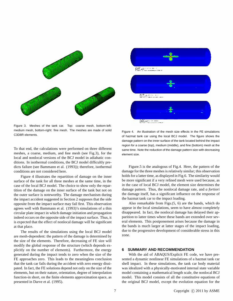
Figure 3. Meshes of the tank car. Top: coarse mesh, bottom-left:
medium mesh, bottom-right: fine mesh. The meshes are made of solid
C3D8R elements.
To that end, the calculations were performed on three differentmeshes, a coarse, medium, and fine mesh (see Fig.3), for thelocal and nonlocal versions of the BCJ model in adiabatic con-ditions. In isothermal conditions, the BCJ model difficultly pre-dicts failure (see Bammann et al. (1993)); therefore, isothermalconditions are not considered here.
Figure 4 illustrates the repartition of damage on the innersurface of the tank for all three meshes at the same time, in thecase of the local BCJ model. The choice to show only the repar-tition of the damage on the inner surface of the tank but not onthe outer surface is noteworthy. The damage mechanism duringthe impact accident suggested in Section 2 supposes that thesideopposite from the impact surface may fail first. This observationagrees well with Bammann et al. (1993)’s simulations of a thincircular plate impact in which damage initiation and propagationindeed occurs on the opposite side of the impact surface. Thus, itis expected that the effect of nonlocal damage will be significantat that place.
The results of the simulations using the local BCJ modelare mesh-dependent: the pattern of the damage is determinedbythe size of the elements. Therefore, decreasing of FE size willmodify the global response of the structure (which depends ex-plicitly on the number of elements). Furthermore, the energygenerated during the impact tends to zero when the size of theFE approaches zero. This leads to the meaningless conclusionthat the tank car fails during the accident with zero energy dissi-pated. In fact, the FE solutions depend not only on the size oftheelements, but on their nature, orientation, degree of interpolationfunction-in short, on the finite elements approximation space, aspresented in Darve et al. (1995).
Figure 4. An illustration of the mesh size effects in the FE simulations
of hazmat tank car using the local BCJ model. The figure shows the
damage pattern on the inner surface of the tank located behind the impact
region for a coarse (top), medium (middle), and fine (bottom) mesh at the
same time. Note the reduction of the damage pattern size with decreasing
element size.
Figure.5 is the analogous of Fig.4. Here, the pattern of thedamage for the three meshes is relatively similar; this observationholds for a latter time, as displayed in Fig.6. The similarity wouldbe more significant if a very refined mesh were used because, asin the case of local BCJ model, the element size determines thedamage pattern. Thus, the nonlocal damage rate, anda fortiorithe damage itself, has a significant influence on the responseofthe hazmat tank car to the impact loading.
Also remarkable from Figs.(5, 6) are the bands, which doappear in the local simulations, seem to have almost completelydisappeared. In fact, the nonlocal damage has delayed theirap-parition to latter times where these bands are extended oversev-eral elements. This postponement arises because the damageinthe bands is much larger at latter stages of the impact loading,due to the progressive development of considerable stress in thiszone.
6 SUMMARY AND RECOMMENDATIONWith the aid of ABAQUS/Explicit FE code, we have pre-
sented a dynamic nonlinear FE simulations of a hazmat tank carshell impact. In these simulations, the tank car body materialwas idealized with a physically-motivated internal state variablemodel containing a mathematical length scale, the nonlocalBCJmodel. This model consists of all the constitutive equations ofthe original BCJ model, except the evolution equation for the
7 Copyright c© 2011 by ASME

Figure 5. An illustration of the introduction of the mathematical length
scale in the BCJ model to reduce the mesh size effects in the FE simu-
lations of hazmat tank car. The contour plots of the damage on the inner
face of the tank are shown for three different meshes at the same time
as in Fig.4: coarse (top), medium (middle), and fine (bottom). Note the
similarity of the damage pattern size for the three meshes.
damage, which is modified into a nonlocal one. Numerical meth-ods to implement this equation in existing BCJ model subrou-tines were also presented.
The results of the simulations show the ability of themathematical length scale to eliminate the pathological mesh-dependency issues while predicting satisfactory hazmat tank carimpact failure, provided that nonlocal damage effects are cou-pled with temperature history effects (adiabatic effects). Thus,the nonlocal BCJ model is a powerful tool that we recommendhazmat tank car fabrication industries incorporate in their virtualdesign tools.
AKNOWLEDGMENTSThe study was supported by the U.S. Department of Trans-
portation, Office of the Secretary, Grant No. DTOS59-08-G-00103. Dr. Esteban Marin and Mrs. Cl ´emence Bouvard aregratefully thanked for their insightful discussions on thetopic.
REFERENCES
[Aravas (1987)] Aravas N. 1987. “On the Numerical Integrationof a Class of Pressure-dependent Plasticity Models,”Int. J.Num. Meth. Engng., 24, 1395-1416.
Figure 6. Another illustration of the mathematical length scale effects in
the hazmat tank car FE simulations. The contour plots of the damage
pattern on the inner surface on the tank are shown for a time greater
the one in Figs.(4, 5). Note here also the similarity between the damage
pattern.
[Bammann et al. (1993)] Bammann D. J., Chiesa M. L., Horste-meyer, M. F., and Weingarten, L. I., 1993. “Failure in DuctileMaterials using Finite Element Methods,” Structural Crash-worhiness and Failure, N. Jones, T. Wierzbicki, ed., ElsevierApplied Science, New York, 1993, pp.1-54.
[Bammann (1988)] Bammann, J.D., 1988. “Modelling theLarge Strain-High Temperature Response of Metals,” in Mod-eling and Control of Casting and Welding Process IV, eds.Giamei, A.F. and Abbaschian, G.J. TMS Publications, War-rendale, PA.
[Bammann and Aifantis (1987)] Bammann, D.J. and Aifantis,E.C., 1987. “A Model for Finite-deformation Plasticity ”,Acta. Mech., 69, 97-117.
[de Borst (1993)] de Borst, R., 1993.“Simulation of Strain Lo-calization: a Reappraisal of the Cosserat Continuum,”,Eng.Comput., 8, 317-332.
[Cocks and Ashby (1980)] Cocks, A.C.F. and Ashby, M.G.,1980. “Intergranular Fracture During Power-Law Creep underMultiaxial Stresses,” Metal Science, Aug-Sept, pp. 395-402.
[Darve et al. (1995)] Darve, F., Hicher, P.-Y., Reynouard J.M.,1995. “Mecanique des Geomateriaux,” Hermes,” Paris.
[Enakoutsa et al. (2007)] Enakoutsa K., Leblond J.B. and Per-rin G., 2007. “Numerical Implementation and Assessmentof a Phenomenological Nonlocal Model of Ductile Rupture,”Comput. Meth. Appl. Mech. Engng., 196, 1946-1957.
[Glema et al. (2000)] Glema, A., Lodygowski, T., and Perzyna,P., 2000. “interaction of deformation Waves and Localiza-
8 Copyright c© 2011 by ASME

tion Phenomena in Inelastic Solids,”Comput. Methods Appl.Mech.Engrg., 183, pp. 123-140.
[Guo et al. (2005)] Guo, Y.B., Wen, Q., and Horstemeyer, M. F.,2005. “An Internal State Variable Plasticity-based Approachto Determine Dynamic Loading History Effets on MaterialProperty in Manufacturing Processes,”Int. Journal of Mechan-ical Sciences, 47, 1423-1441.
[Gurson (1977)] Gurson A.L. 1977. “Continuum Theory ofDuctile Rupture by Void Nucleation and Growth: Part I -Yield Criteria and Flow Rules for Porous Ductile Media,”ASME J. Engng. Materials Technol., 99, 2-15.
[Halphen and Nguyen (1975)] Halphen B. and Nguyen Q.S.,1975. “Sur les Materiaux Standards Generalises,”Journal deMecanique, 14, 39-63, in French.
[Horstemeyer et al. (2000)] Horstemeyer, M.F., Matalanis,M.M., Siebe, M.L., 2000. “Micromechanical Finite ElementCalculations of Temperature and Void Configuration Effectson Void Growth and Coalescence,”international Journal ofPlasticity, 16, pp. 979-1015.
[Johnson (1987)] Johnson, W., 1987. “Henri Tresca as the Orig-inator of Adiabatic Heat Lines”,Int. J. Mech. Sci., 29, pp.301-310.
[Krieg and Krieg (1977)] Krieg R.D., and Krieg D.B., 1977.“Accuracies of Numerical Solution Methods for the Elastic-Perfectly Plastic Model,”ASME Pressure Vessel Tech., 99,510.
[Leblond et al. (1994)] Leblond, J.B., Perrin, G., and Devaux,J., 1994. “Bifurcation Effects in Ductile Metals with NonlocalDamage”,ASME J. Applied . Mech., 61, 236-242.
[Muhlhaus (1986)] Muhlhaus, H.-B., 1986. “Shear Band Anal-ysis in Granular Materials by Cosserat Theory,”Ing. Arch., 56,389-399.
[Pijaudier-Cabot and Bazant (1987)] Pijaudier-Cabot, G. andBazant, Z.P., 1987. “Nonlocal Damage Theory”,ASCE J. En-grg. Mech., 113, 1512-1533.
[Ramaswamy and Aravas (1998)] Ramaswamy, S. and Aravas,N., 1998. “Finite Element Implementation of Gradient Plas-ticity Models part I: Gradient-dependent Yield Functions,”Mech. Eng., 163, pp. 11-32.
[Saanouni et al. (1989)] Saanouni, K., Chaboche, J.L. andLesne, P.M., 1989. “On the Creep Crack-growth Predictionby a Nonlocal Damage Formulation,”European Journal ofMechanics A/Solids,8, pp. 437-459.
[Tang et al. (2008a)] Tang, Y.H., Yu, H., Gordon, J.E., Jeong,D.Y., and Perlman, A.B, 2008. “Analyses of Railroad TankCar Shell Impacts Using Finite Element Method,”,Pro-ceedings of the 2008 IEEE/ASME Joint Rail Conference,JRC2008-63014.
[Tang et al. (2008b)] Tang, Y.H., Yu, H., Gordon, J.E., Jeong,D.Y., 2008. “Finite Element Analyses of Railroad Tank CarHead Impacts,”,Proceedings of the 2008 ASME Rail Trans-portation Division Fall Technical Conference, RTDF2008-
74022.[Taylor and Quinney (1934)] Taylor, G.I., and Quinney, H.,
1934. “The Latent Energy Remaining in a Metal after ColdWorking,” Proc. Roy. Lond. Soc., Vol. A145.
[Tvergaard and Needleman (1997)] Tvergaard, V. and Needle-man, A., 1997. “Nonlocal Effects on Localization in a Void-sheet,”Int. J. Solids and Struct., 34, pp. 2221-2238.
[Tvergaard and Needleman (1995)] Tvergaard V. and Needle-man A., 1995. “Effects of Nonlocal Damage in Porous PlasticSolids”, Int. J. Solids Structures, 32, 1063-1077.
[Rousselier (1981)] G. Rousselier, 1981. “Finite DeformationConstitutive Relations and Ductile Fracture,” Edited byNemat-Nasser, North-Holland, Amsterdam, pp. 201-217.
[Yamaguchi et al. (1992)] Yamaguchi, K., Ueda, S., Jan, F.S.,Takakura, N., 1992. “Effects of Strain Rate and Temperatureon Deformation Resistance of Stainless Steel,” MechanicalBehavior of Materials-VI, vol. 3, Headington Hill Hall, Perg-amon Press, Oxford, pp. 805-810.
[Zukas (1990)] Zukas, J.A., Editor 1990. “High Velocity ImpactDynamic,” John Wiley Son, Inc. New York.
9 Copyright c© 2011 by ASME