jt to catia composer user guide - theorem and documentation/jtc5c/jtc5c_jt-catia...the jt to catia...
TRANSCRIPT

Publish 3D JT to CATIA Composer Interface Product Range JTC5C
USER GUIDE
Document Revision: 2.0 Issued: 26/10/2018

Publish 3D JT to CATIA Composer Interface
1 | P a g e ©Theorem Solutions 2018
This software and related documentation are proprietary to
Theorem Solutions Limited.
© Copyright 2018 Theorem Solutions Limited
Theorem Solutions Limited, Theorem House, Marston Park,
Bonehill Road, Tamworth, Staffordshire,
B78 3HU, England
Telephone: +44 (0) 1827 305 350
Fax: +44 (0) 1827 692 63 E-mail: [email protected]
Website: http://www.TheoremSolutions.com
Document Control:
Status: Draft
Revision: 2.0
Date of issue: 26/10/2018
Amendment Summary:
Issue Date Commentary Initials
1.0 02/02/18 Final for customer release TL
2.0 03/08/18 Updates to include JT Composer Enterprise Sync interface TL
© THEOREM SOLUTIONS 2016
Publish 3D JT to CATIA Composer Interface
2 | P a g e ©Theorem Solutions 2018
Contents
Overview of Publish 3D JT to CATIA Composer ......................................................................... 4
About Theorem ......................................................................................................................4
What is Publish 3D? ................................................................................................................4
The Publish 3D JT to CATIA Composer Interface ....................................................................5
Primary Product Features .......................................................................................................5
Primary Product Benefits .......................................................................................................6
Getting Started .......................................................................................................................... 7
Documentation .......................................................................................................................7
Installation Media ...................................................................................................................7
Software and License Installation .............................................................................................. 7
The System Configuration Interface .......................................................................................... 7
The “License Configuration” Page ..........................................................................................7
The “Other Configuration” Page ............................................................................................8
Accessing the System Configuration Interface Post Installation ............................................... 9
Supported JT Data Structures .................................................................................................. 10
Supported Methods Using the JT to CATIA Composer Converter ........................................... 10
Default Process Reporting ....................................................................................................... 11
Setting TSC_TEMP_DIR ........................................................................................................ 11
Conversion Report Files ....................................................................................................... 11
Intermediate Processing Files.............................................................................................. 11
Interactive Usage of JT to CATIA Composer ............................................................................ 13
Using the CATIA Composer Sync interface .............................................................................. 15
Using the CATIA Composer Enterprise Sync interface ............................................................ 16
Using the ComposerConverter.exe Mechanism .................................................................. 16
Processing Large Assemblies with the CATIA_Composer_lap.cmd ..................................... 17
Using the jt_composer.cmd Script ...................................................................................... 17
Processing JT Assembly Structure Only ............................................................................... 18
Conversion Processing Error Messages ................................................................................... 19

Publish 3D JT to CATIA Composer Interface
3 | P a g e ©Theorem Solutions 2018
ComposerConverter.exe Error Message Table ................................................................... 19
jt_composer.cmd Error Message Table ............................................................................... 20
Theorem License Manager Errors ....................................................................................... 20
Configuring JT to CATIA Composer Options ............................................................................ 21
JT Options File Settings ........................................................................................................ 21
Using an Alternate Options File ........................................................................................... 23
JT to CATIA Composer Property Filtering ................................................................................ 23
Publish 3D JT to CATIA Composer Interface
4 | P a g e ©Theorem Solutions 2018
Overview of Publish 3D JT to CATIA Composer
About Theorem
Theorem Solutions is a world leader in the field of Engineering Data Services and Solutions. This leadership position stems from the quality of our technology and the people in the company. Quality comes not only from the skills and commitment of our staff, but also from the vigorous industrial use of our technology & services by world leading customers.
We are proud that the vast majority of the world's leading Automotive, Aerospace, Defence, Power Generation and Transportation companies and their Supply chains use our products and services daily. Working closely with our customers, to both fully understand their requirements and feed their input into our development processes has significantly contributed to our technology and industry knowledge.
Theorem Solutions is an independent UK headquartered company incorporated in 1990, with sales and support offices in the UK and USA. Theorem has strong relationships with the major CAD and PLM vendors, including; Autodesk, Dassault Systemes, ICEM Technologies (a Dassault company), PTC, SolidWorks, Spatial Technology and Siemens PLM Software. These relationships enable us to deliver best in class services and solutions to engineering companies worldwide.
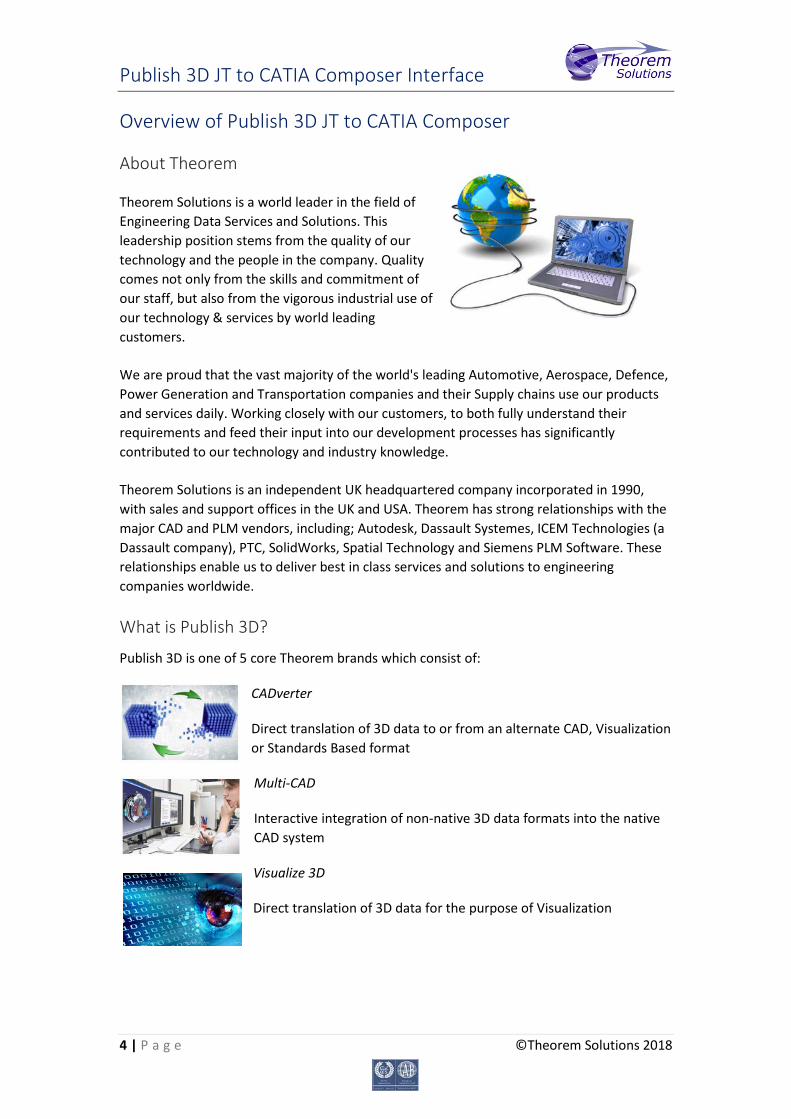
What is Publish 3D?
Publish 3D is one of 5 core Theorem brands which consist of:
CADverter
Direct translation of 3D data to or from an alternate CAD, Visualization or Standards Based format
Multi-CAD
Interactive integration of non-native 3D data formats into the native CAD system
Visualize 3D
Direct translation of 3D data for the purpose of Visualization

Publish 3D JT to CATIA Composer Interface
5 | P a g e ©Theorem Solutions 2018
Publish 3D
The creation of documents enriched with 3D content
Process Automation
Applications to automate any Data Exchange and collaboration processes
The Publish 3D JT to CATIA Composer Interface
The Publish 3D JT to CATIA Composer Interface may be installed locally on a single client or shared on a number of machines each accessing a central network-floating license. The Publish 3D JT to CATIA Composer Interface is a uni-directional direct database converter between the Siemens JT file format and the Dassault Systemes CATIA Composer application. CATIA Composer allows you to repurpose existing 3D design data to more rapidly create and update high quality product deliverables including documentation, technical illustrations, animations, and interactive 3D experiences. The JT to CATIA Composer interface enables the user to import all forms of 3D Mechanical Design Geometry and Assembly and 3D Dimensions and Annotation data, together with system defined attribute information, colour information, from JT into the CATIA Composer application. This product is designed for companies using CATIA Composer for the documentation creation with a requirement to import data based upon the JT format. The JT converter interface can be invoked in either interactively from within the CATIA Composer interface itself or alternatively in batch mode. Batch mode processing is supported using either the CATIA Composer Sync user interface or via the CATIA Composer Enterprise Sync technology which supports command line invocation. Therefore, allowing the JT conversion process to be integrated into any process-oriented operation.
Primary Product Features
• Converts all types of geometry, wire frame, surfaces, trimmed surfaces (faces) and solid models.
• Converts 3D dimensions and annotations
• Converts assembly structure between both systems.
• Converts attribute data including metadata properties and colour information.
• Integrated with the CATIA Composer installation.
• The conversion process can be run Interactively, or in Batch Mode
Publish 3D JT to CATIA Composer Interface
6 | P a g e ©Theorem Solutions 2018
• CATIA Composer Enterprise Sync command line interface allows process integration into any workflow or automated process.
• Uses the Siemens JTOpen API and Dassault Systems CATIA Composer API to read and
write the respective data formats.
Primary Product Benefits
• Being a direct database converter all pre and post processing is eliminated, saving time.
• Reduce costs due to processing time and increase overall conversion success levels by filtering input data and focusing the conversion to only those elements required.
• Reduce costs and risks associated to accessing the wrong version of data by
integrating the conversion process into any related business processes.
• With over 20 years of industrial use Theorem translation products robustness and quality is well proven, reducing your business risk.
This document will focus specifically on guidance for the use of the Publish 3D JT to CATIA Composer product. For information regarding any of Theorem’s product ranges please contact [email protected]

Publish 3D JT to CATIA Composer Interface
7 | P a g e ©Theorem Solutions 2018
Getting Started
Documentation A copy of the latest documentation for all Theorem Solutions products can be found on our web site at:
http://www.theorem.com/Documentation
For the Publish 3D JT to CATIA Composer product there is a specific link that provides user documentation in the form of PDF and Tutorials. For this product navigate to the Publish 3D JT CATIA Composer section.
Installation Media The latest copy of each release is specified in the Product Release Document associated with each specific release. A copy of the current product release notes can be found on the Theorem Solutions web site at:
http://www.theorem.com/Product-Release-Notes Simply download the Product Release Document and select the hyperlink within the document to download the installation media. Alternatively, you can request a copy of the software to be shipped on a physical CD media. Please contact your sales representative mailto:[email protected] to arrange the shipment of the physical CD media.
Software and License Installation
The software installation and License configuration processes are fully defined in separate documents together with supporting videos showing the processes. Please refer to the documentation website http://www.theorem.com/Documentation for complete installation instructions.
The System Configuration Interface
Towards the end of the software installation process a dialog panel appears with the initial label “License Configuration”. This panel has two separate pages, the initial page is labelled “License” and is used to configure the Theorem License server. The second page is labelled “Other” and allows you to configure other settings.
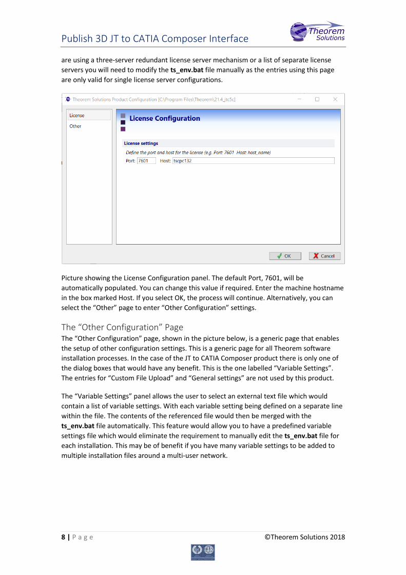
The “License Configuration” Page The “License Configuration” page, shown in the picture below, is the initial page that is displayed when the System Configuration panel is displayed. To configure the license server simply enter the machine hostname of the of the license server machine in the dialog box provided. This will update the ts_env.bat file in the software installation folder. Note, if you
Publish 3D JT to CATIA Composer Interface
8 | P a g e ©Theorem Solutions 2018
are using a three-server redundant license server mechanism or a list of separate license servers you will need to modify the ts_env.bat file manually as the entries using this page are only valid for single license server configurations.
Picture showing the License Configuration panel. The default Port, 7601, will be automatically populated. You can change this value if required. Enter the machine hostname in the box marked Host. If you select OK, the process will continue. Alternatively, you can select the “Other” page to enter “Other Configuration” settings.
The “Other Configuration” Page The “Other Configuration” page, shown in the picture below, is a generic page that enables the setup of other configuration settings. This is a generic page for all Theorem software installation processes. In the case of the JT to CATIA Composer product there is only one of the dialog boxes that would have any benefit. This is the one labelled “Variable Settings”. The entries for “Custom File Upload” and “General settings” are not used by this product.
The “Variable Settings” panel allows the user to select an external text file which would contain a list of variable settings. With each variable setting being defined on a separate line within the file. The contents of the referenced file would then be merged with the ts_env.bat file automatically. This feature would allow you to have a predefined variable settings file which would eliminate the requirement to manually edit the ts_env.bat file for each installation. This may be of benefit if you have many variable settings to be added to multiple installation files around a multi-user network.

Publish 3D JT to CATIA Composer Interface
9 | P a g e ©Theorem Solutions 2018
Picture showing the “Other Configuration” page. Note, for the JT to CATIA Composer only the “Variable settings” entry would have any benefit from being used.
Accessing the System Configuration Interface Post Installation
Following the completion of the installation if you want to make any changes then you can launch the System Configuration Interface again by using the configure.exe command located in the bin folder of the software installation. Running this command launches the System Configuration Interface and allows you to modify any of the settings that were originally entered. Any changes that are made are automatically stored in the ts_env.bat file.

Publish 3D JT to CATIA Composer Interface
10 | P a g e ©Theorem Solutions 2018
Supported JT Data Structures
JT data can be created using several different representations. These include the JT file formats of;
• MONOLITHIC – this representation uses a single JT file that contains all assembly structure and geometry data in a single file.
• PER_PART – this representation uses a single JT file for the assembly structure and a folder of a similar name which holds all the JT files for each of the component parts
• FULL_SHATTER – this representation uses a separate JT file for each of the nodes of assembly structure as well as separate JT files for the component parts. Using this representation allows the consumer of the data to selectively look at individual parts or subassemblies without having to access the complete assembly structure. However, it does demand that the file names are known to correctly access the top-level assembly file to ensure you are viewing the complete assembly.
• PLMXML + JT – this representation uses a single PLMXML file for the assembly structure. The subordinate JT component parts are referenced from within the PLMXML file. These subordinate parts are referenced using either an absolute or relative path to the files. However, there is a normal convention whereby the subordinate JT files are presented in the same folder as the PLMXML file itself. Technically the subordinate parts of a PLMXML file may be referenced using any defined representation other than JT, including native CAD formats such as CATIA V5 CATParts. In these situations, the PLMXML structure could be processed on its own using the JT to CATIA Composer converter. The referenced CATParts being processed independently using the standard CATIA Composer capabilities.
• STEP AP242 (BOM) + JT – this representation uses a STEP AP242 (BOM) XML format file to define the assembly structure. The subordinate JT component parts being referenced externally.
The JT to CATIA Composer converter supports the processing of all of these JT data representations using all of the available interfaces, Interactive Composer, Composer Sync and Composer Enterprise Sync.
Supported Methods Using the JT to CATIA Composer Converter
Once the software is installed and licensed, the product will be ready to be used. There are three separate methods available for running the JT to CATIA Composer converter;
1. Interactive, from within the CATIA Composer application using the File Open interface. This method is supported using either a Theorem JT to CATIA Composer Interactive, Sync or Enterprise Sync license
Publish 3D JT to CATIA Composer Interface
11 | P a g e ©Theorem Solutions 2018
2. Batch processing – using the CATIA Composer Sync interface. This method is supported using either a Theorem JT to CATIA Composer Sync or Enterprise Sync license.
3. Command line processing – using either the direct Composer converter executable, or the JT Composer Enterprise Sync or Large Assembly Processing batch scripts with a Windows command shell. All these methods of running the converter from the command line are supported when using a Theorem JT to CATIA Composer Enterprise Sync license.
Default Process Reporting
As part of the standard JT to CATIA Composer processing several intermediate logs are generated in addition to the Composer output. These log files are not normally needed and can often be ignored. However, if you specifically want to capture an audit trail of the conversion process, or if you need to analyse the reason why the output had not been created as expected, then knowledge of the location of these files and their location is beneficial.
Setting TSC_TEMP_DIR The variable TSC_TEMP_DIR is used to define the location of temporary process log files for each file processed. The variable is set in the installation file %TS_INST%\ts_env.bat and by default the value is set to be equivalent to the users %TEMP% variable setting e.g. set TSC_TEMP_DIR=%TEMP%. Therefore, the location of the process log files would normally be set to be written to the users local temporary file location. This variable can be set to any alternate required location, either by changing the location in the %TS_INST%\ts_env.bat, which would change the setting for all users. Alternatively, if a dynamic location is required then the variable could be set prior to starting any of the JT to CATIA Composer interfaces in a shell prior to starting the interface.
Conversion Report Files There are three specific report logs generated for each conversion. The filenames for these files are derived from the input JT filename that is being processed. The files have the extensions .rpt, .err and _viewer.log. Therefore if a JT file named alternator.jt was being processed the files alternator.rpt, alternator.err and alternator_viewer.log would be created would be created in the active %TSC_TEMP_DIR% folder.
The two primary files for analysis processing issues are the .rpt and the _viewer.log files. The .rpt file contains an overview report of the conversion process. It would also contain messages related to any overall licensing issues. The “_viewer.log” file is a detailed audit log of the JT data being read. It will identify the specific types of data that has been processed including information related to assembly structure, associated property values and product manufacturing information.
Intermediate Processing Files On occasions, especially if a conversion process has had a catastrophic failure, you may also find an additional file with the extension “.gco” in the %TS_TEMP_DIR% folder. Files with
Publish 3D JT to CATIA Composer Interface
12 | P a g e ©Theorem Solutions 2018
this extension are created for all conversions. However, under normal circumstances the files are removed at the end of the processing. If the process abnormally terminates then on occasions these files can be left in the %TS_TEMP_DIR% folder.

Publish 3D JT to CATIA Composer Interface
13 | P a g e ©Theorem Solutions 2018
Interactive Usage of JT to CATIA Composer
The JT to CATIA Composer converter is automatically invoked when a JT file is selected from the CATIA Composer File Open menu.
During the processing a dialog is displayed showing the progress of the translation process. If any problems occur during the processing the information will be displayed in this dialog window.
Once the translation is complete the JT data is displayed in the CATIA Composer graphics window. Any assembly structure is shown in the Composer Assembly window and all associated JT properties are available in the Composer Property area.
Having imported the JT data, it can now be fully utilized within the CATIA Composer application
Saving the active session will export the translated data to the file system using the standard CATIA Composer file format.
Publish 3D JT to CATIA Composer Interface
14 | P a g e ©Theorem Solutions 2018
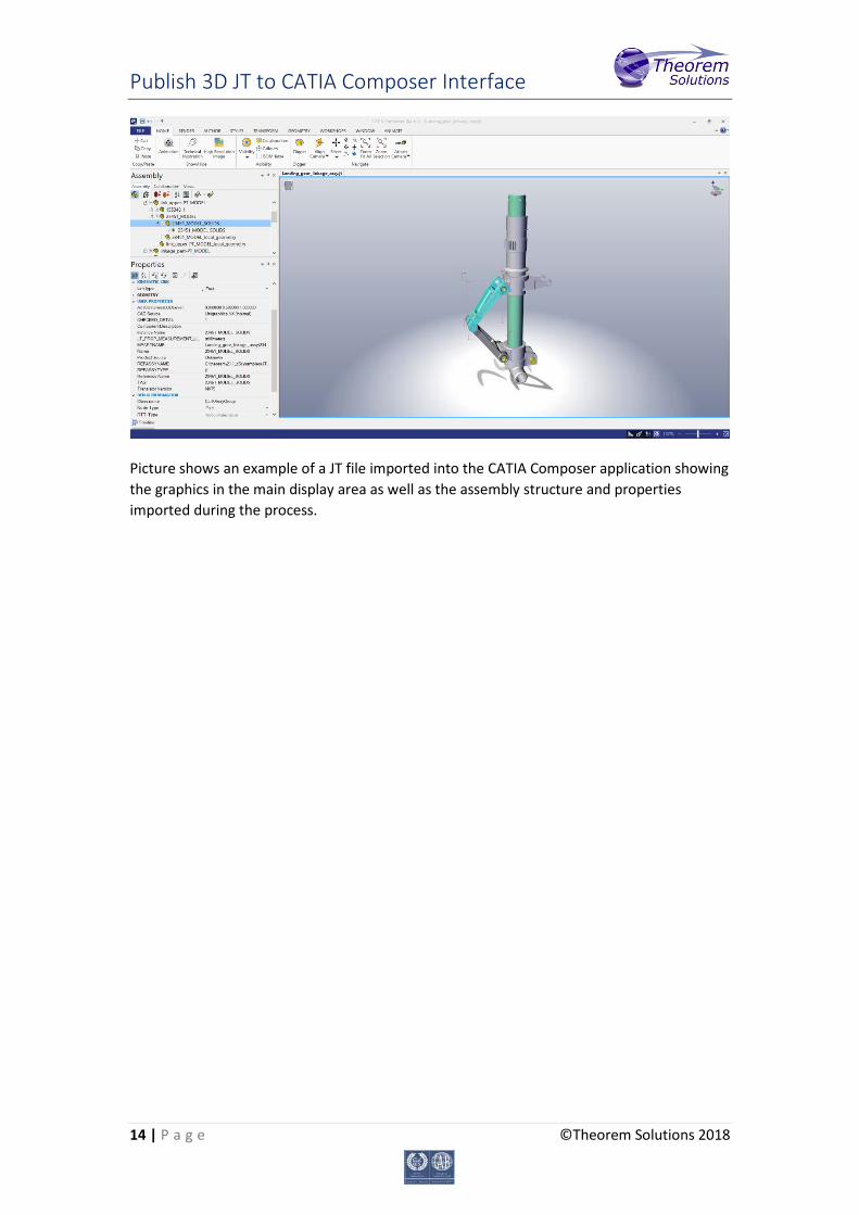
Picture shows an example of a JT file imported into the CATIA Composer application showing the graphics in the main display area as well as the assembly structure and properties imported during the process.
Publish 3D JT to CATIA Composer Interface
15 | P a g e ©Theorem Solutions 2018
Using the CATIA Composer Sync interface
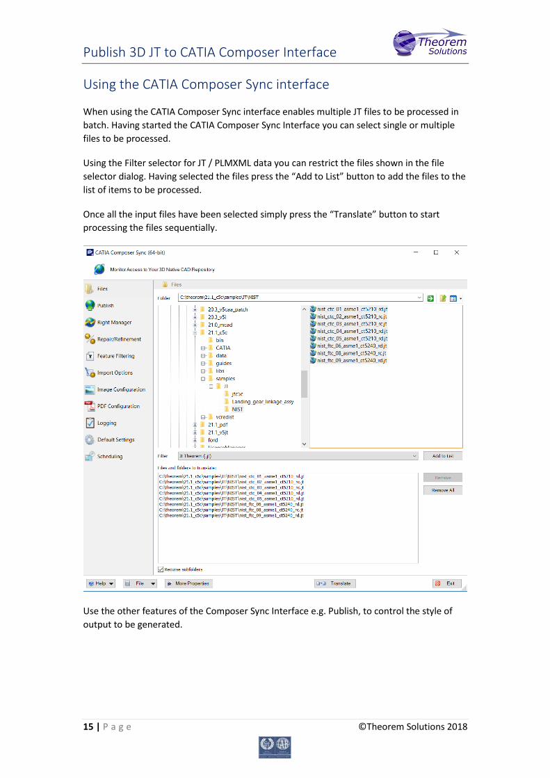
When using the CATIA Composer Sync interface enables multiple JT files to be processed in batch. Having started the CATIA Composer Sync Interface you can select single or multiple files to be processed.
Using the Filter selector for JT / PLMXML data you can restrict the files shown in the file selector dialog. Having selected the files press the “Add to List” button to add the files to the list of items to be processed.
Once all the input files have been selected simply press the “Translate” button to start processing the files sequentially.
Use the other features of the Composer Sync Interface e.g. Publish, to control the style of output to be generated.
Publish 3D JT to CATIA Composer Interface
16 | P a g e ©Theorem Solutions 2018
Using the CATIA Composer Enterprise Sync interface
The CATIA Composer Enterprise Sync interface allows the converter to be invoked from a command line prompt. Consequently, it is possible to integrate the translation of JT data to CATIA Composer output as part of any workflow, including the integration of the converter into any PDM/PLM process.
There are three methods provided for running the converter using the Enterprise Sync command line mode. These are;
1. %TS_INST%\bin\ComposerConverter.exe – standard translation command line executable for processing JT or PLMXML files directly as a single event.
2. %TS_INST\bin\CATIA_Composer_lap.cmd – batch script process which separates the processing of the JT assembly data from the processing of the subordinate part geometry files. This method will automatically generate the CATIA Composer output in a shattered file format consisting of a “.smgXml” top level CATIA Composer assembly file with subordinate “.smgXml/.smgGeom” files for the subordinate component part files.
3. %TS_INS%\bin\jt_composer.cmd – batch script process which supports the processing of JT files outputting the results into a nominated folder. The format of the output can be further controlled by the addition of a JT options file with parameter settings to influence the processing.
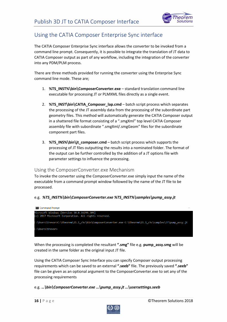
Using the ComposerConverter.exe Mechanism To invoke the converter using the ComposerConverter.exe simply input the name of the executable from a command prompt window followed by the name of the JT file to be processed.
e.g. %TS_INST%\bin\ComposerConverter.exe %TS_INST%\samples\pump_assy.jt
When the processing is completed the resultant “.smg” file e.g. pump_assy.smg will be created in the same folder as the original input JT file.
Using the CATIA Composer Sync Interface you can specify Composer output processing requirements which can be saved to an external “.seeb” file. The previously saved “.seeb” file can be given as an optional argument to the ComposerConverter.exe to set any of the processing requirements
e.g. …\bin\ComposerConverter.exe …\pump_assy.jt …\usersettings.seeb

Publish 3D JT to CATIA Composer Interface
17 | P a g e ©Theorem Solutions 2018
The CATIA Composer output would then be created in-line with the specific converter options defined in the input “.seeb” file.
Processing Large Assemblies with the CATIA_Composer_lap.cmd The CATIA_Composer_lap.cmd is specifically designed for processing large assemblies that are created in either native JT using either PER_PART or FULL_SHATTER data or PLMXML files with subordinate JT part files. In doing so the batch script will process the assembly structure separately from processing the subordinate part files and force the creation of shattered CATIA Composer output. Therefore the output will consist of a top level “.smgXml” format file for the overall assembly structure. The subordinate part files will be recreated using “.smgXML/.smgGeom” format output. Opening the top level assembly “.smgXml” file within CATIA Composer will open all of the subordinate data automatically. e.g. %TS_INST%\bin\CATIA_Composer_lap.cmd %TS_INST%\samples\landing_gear.jt The resultant output “.smgXml & .smgGeom” files will automatically be written to the same folder that the input data was in. Alternatively, an additional optional argument can be entered which will nominate the folder name to be used when creating the output. e.g. …\bin\CATIA_Composer_lap.cmd …\landing_gear.jt C:\output_folder Using this method, the output data will be written to the nominated folder.
Using the jt_composer.cmd Script The jt_composer.cmd script provided in the %TS_INST%\bin folder is designed for automating the processing of JT input data. It also allows the user to control the location of the output creation folder, including the location of process log files. In addition, the user can optionally specify a JT process configuration options file to be used for the conversion.
e.g. %TS_INST%\bin\jt_composer.cmd C:\input\any.jt C:\output_folder <JT_opt_file> The jt_composer.cmd script manages the output creation by using the following process;
1. It validates that the JT input data is available for processing. If it cannot locate the JT input data an error message is reported, and the process terminates.
2. It verifies that the output folder specified exists. If it doesn’t already exist, the process will attempt to create the specified output folder. If it’s unable to do so then then an error message is reported, and the process terminates.
3. It sets the value of TS_TEMP_DIR to the location of the output folder. This ensures that both the Composer output and processing log files are held in the same location.
4. It sets the variable TS_MCAD_READ_OPTIONS_FILE to reference either the name of the options file given as the third command line argument. Alternatively, it sets the variable to point to the default JT options file %TS_INST%\ data\jt\jt_3dvia_opts.txt
5. The nominated options file identified in step #5 is parsed for two specific options being set, read_pmi and output_fullshatter. These settings are used to determine the processing requirements of PMI processing as well as SMG output settings. The output_fullshatter option triggers the SMG output to be created using the smgGeom/smgXml representation. These settings are then reflected in a temporary Composer SEEB file that is automatically authored.
Publish 3D JT to CATIA Composer Interface
18 | P a g e ©Theorem Solutions 2018
6. The automatic SEEB file is created using the naming convention of ts_seeb_<jt_filename>.seeb
7. The standard ComposerConvertor.exe is finally executed with the name of the JT file and the derived SEEB file being used as arguments to the process.
8. The process terminates with an appropriate error status being set. Note, to monitor the jt_composer.cmd script processing set the environment variable TSC_ECHO=on in the command shell prior to running the process. Echo of the lines of the batch script will be echoed to the screen to analyse the processing in detail. In addition, the temporary SEEB file, which is normally deleted at the end of the processing, will be retained in the output folder for further investigation.
Processing JT Assembly Structure Only When processing JT assemblies there are situations where you may only want to process the assembly structure and not the subordinate geometry. For example, if you are processing a PLMXML assembly structure which references subordinate CATPart component files, rather than conventional JT components, then you could process only the PLMXML assembly structure in isolation of processing the CATPart files using the standard Composer interface. To process the assembly structure only use the jt_composer.cmd script and reference a JT options file that contains the struct_read option setting. The struct_read option will limit the translator to only processing the assembly structure. Consequently, all subordinate geometry files will be ignored during the translation process. See the section titled “Configuring JT to CATIA Composer Options” for detailed information on using alternate options files.

Publish 3D JT to CATIA Composer Interface
19 | P a g e ©Theorem Solutions 2018
Conversion Processing Error Messages
The JT CATIA Composer conversion executable, ComposerConverter.exe, reports several specific error messages that indicate the completion status of the conversion process and sets an equivalent exit status when the process is completed. In addition, the jt_composer.cmd script reports several additional errors and sets an equivalent exit status when the processing is completed.
ComposerConverter.exe Error Message Table The following table lists the error codes and associated messages returned from the ComposerConverter.exe executable.
Code Error Message
0 Success
1 Multiple unspecified errors
2 License issue
3 Specified JT input file does not exist
4 Settings SEEB file specified does not exist
5 Referenced .smgGeom or .smgXml file not found
6 Resource not found
7 Composer file locked by another application
8 SMG file not generated for unknown reason
9 Incompatible hardware settings
Note, the ComposerConverter.exe command will set the error condition #2 when errors are identified with respect the CATIA Composer licensing. It does not set an error condition if the Theorem license server reports any issues.
Publish 3D JT to CATIA Composer Interface
20 | P a g e ©Theorem Solutions 2018
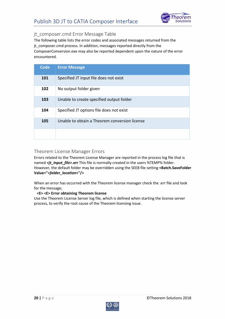
jt_composer.cmd Error Message Table The following table lists the error codes and associated messages returned from the jt_composer.cmd process. In addition, messages reported directly from the ComposerConversion.exe may also be reported dependent upon the nature of the error encountered.
Code Error Message
101 Specified JT input file does not exist
102 No output folder given
103 Unable to create specified output folder
104 Specified JT options file does not exist
105 Unable to obtain a Theorem conversion license
Theorem License Manager Errors Errors related to the Theorem License Manager are reported in the process log file that is named <jt_input_file>.err This file is normally created in the users %TEMP% folder. However, the default folder may be overridden using the SEEB file setting <Batch.SaveFolder Value="<folder_location>"/> When an error has occurred with the Theorem license manager check the .err file and look for the message; <E> <E> Error obtaining Theorem license Use the Theorem License Server log file, which is defined when starting the license server process, to verify the root cause of the Theorem licensing issue.
Publish 3D JT to CATIA Composer Interface
21 | P a g e ©Theorem Solutions 2018
Configuring JT to CATIA Composer Options
There are several Theorem optional settings available to configure the conversion functionality when running the JT to CATIA Composer. These options are defined in the default JT options file located in software installation folder in the file named %TS_INST%\data\jt\jt_3dvia_opts.txt
The options available are documented within the file itself. The format of the document is such that any line that begins with an asterisk, *, character will be treated as a comment. All other lines will be treated as active option settings.
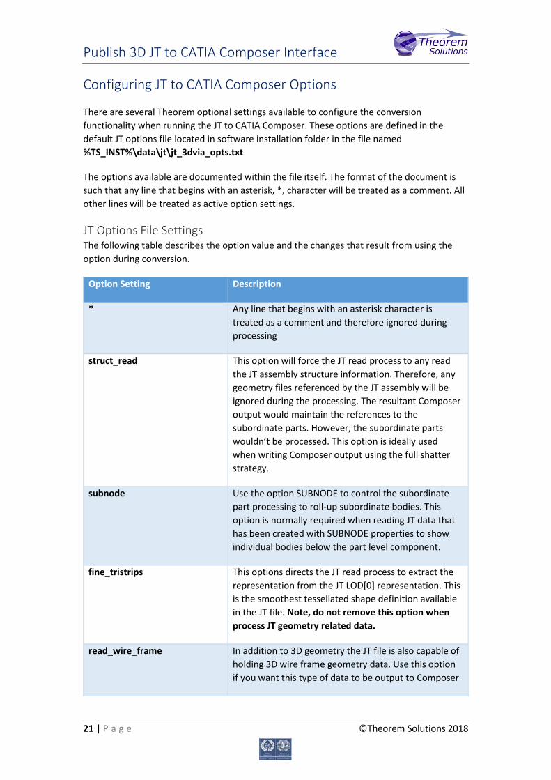
JT Options File Settings The following table describes the option value and the changes that result from using the option during conversion.
Option Setting Description
* Any line that begins with an asterisk character is treated as a comment and therefore ignored during processing
struct_read This option will force the JT read process to any read the JT assembly structure information. Therefore, any geometry files referenced by the JT assembly will be ignored during the processing. The resultant Composer output would maintain the references to the subordinate parts. However, the subordinate parts wouldn’t be processed. This option is ideally used when writing Composer output using the full shatter strategy.
subnode Use the option SUBNODE to control the subordinate part processing to roll-up subordinate bodies. This option is normally required when reading JT data that has been created with SUBNODE properties to show individual bodies below the part level component.
fine_tristrips This options directs the JT read process to extract the representation from the JT LOD[0] representation. This is the smoothest tessellated shape definition available in the JT file. Note, do not remove this option when process JT geometry related data.
read_wire_frame In addition to 3D geometry the JT file is also capable of holding 3D wire frame geometry data. Use this option if you want this type of data to be output to Composer

Publish 3D JT to CATIA Composer Interface
22 | P a g e ©Theorem Solutions 2018
read_pmi
dim2_pmi
The read_pmi and dim2_pmi options work together. Specify these options if you want to read the JT PMI data and export it to the Composer output.
pmi_colour <colour> When reading PMI data from JT there is often no colour associated with the data. Using the option pmi_colour followed by one of the available colour selections, BLUE, GREEN, WHITE, BLACK, RED, allows the colour of the PMI representation in Composer to be controlled.
diagnostics debug info
There are three individual options available to increase the volume of data reported to the conversion report files. All these options will increase the volume of data written to the report file. Therefore, they are only recommended to be used when analysing problems related to conversion failures.
single_file If a JT assembly is defined with mixed units, e.g. some parts are defined in mm and other defined in inches, it is necessary to ensure that the data is consolidated into a single unified representation. Do not remove this option when process JT geometry related data if you’re unsure as to the mixed unit content.
cad_prop_map_file <filename> When processing JT files that contain properties, this function enables the control of which properties are to be read and which are to be ignored. In addition, a facility to change the JT property label during the import process is also supported. The default property mapping file is %TS_INST%\data\jt\jt_3dvia_property_mapping.txt
read_occurrences create_occurrences
When processing PLMXML files that contain unique instance occurrence properties it is necessary to enable the property data to be read and expand the structure representation to enable the instance occurrence properties to be written to the Composer output. Use both options when processing PLMXML data of this type.
output_fullshatter The output_fullshatter option is ONLY processed by the jt_composer.cmd script. When used the jt_composer.cmd script will create a SEEB file with the necessary settings to output the Composer data using the full shatter smgGeom/smgXml format output.
Publish 3D JT to CATIA Composer Interface
23 | P a g e ©Theorem Solutions 2018
Using an Alternate Options File Editing this file will impact all subsequent translations. Alternatively, if you want to have different sets of optional settings available for different translation then you can copy the default file and create multiple options files. Then to use an alternate set of options set the environment variable TS_MCAD_READ_OPTIONS_FILE to point to the filename of the alternate options file.
JT to CATIA Composer Property Filtering
By default, all the JT properties with their associated property values will be written into the CATIA Composer output. However, if you want to manipulate this process to either restrict which properties are output, or alternatively change the property name during processing such that the input property name is mapped to a different name in the CATIA Composer output, there is a property mapping facility available. The option to nominate a property mapping file is defined in the CATIA Composer JT options file, %TS_INST%\data\jt\jt_3dvia_opts.txt. A default mapping file is also provided, %TS_INST%\data\jt\jt_3dvia_property_mapping.txt The format of the mapping file is documented within the example file itself.