ju phd dissertation finaletd feb-07
TRANSCRIPT

ABSTRACT
JU, BU SEOG. Seismic Fragility of Piping System. (Under the direction of Abhinav Gupta.)
This dissertation presents a probabilistic fragility assessment for piping systems to
mitigate the seismic hazards. The percentage of construction cost for nonstructural
components such as mechanical and electrical equipments, medical equipments, and piping
systems is over 80% of the total cost in critical facilities. This research is conducted under
the NEES Grand Challenge Project “Simulation of the Seismic Performance of Nonstructural
Systems”. It focuses on characterizing the seismic performance of threaded Tee-joints in
actual piping system and incorporating the experimentally observed behavior in a system
level piping analysis with the purpose of evaluating piping fragilities. A key step in this
process is analyze the experimentally observed moment-rotation relationship of threaded
Tee-joints and use it to characterize the appropriate limit-state. A nonlinear finite element
model for the threaded Tee-joint, validated against the experimental results, is then
incorporated in the complete piping system model in order to facilitate system level piping
analysis and fragility assessment. More specifically, the research presented in this
dissertation focuses on evaluating fragility for the limit-state characterized to represent
“First-Leakage” failure at the threaded Tee-joint. Finally, the effect of building performance
on the piping fragility is also evaluated by considering a high rise 20-story and a low rise 5-
story building. Differences in piping fragility are evaluated for piping located in buildings
that remain linear as well as that exhibit significant nonlinear behavior. Variation in fragility
due to location of piping at different floor levels is also explored.

© Copyright 2011 by Bu Seog Ju
All Rights Reserved
Seismic Fragility of Piping System
by Bu Seog Ju
A dissertation submitted to the Graduate Faculty of North Carolina State University
in partial fulfillment of the requirements for the Degree of
Doctor of Philosophy
Civil Engineering
Raleigh, North Carolina
2012
APPROVED BY:
_______________________________ _______________________________ John Baugh Mervyn Kowalsky
_______________________________ _______________________________ Abhinav Gupta Vernon Matzen Chair of Advisory Committee

ii
DEDICATION
To My Family

iii
BIOGRAPHY
Bu Seog Ju was born in March 5th, 1976 in Tae-An, Korea. He received a Bachelor
of Science in Civil Engineering at KyungHee University in February, 2002, and decided to
study abroad in the United States. He started his Master’s program at North Carolina State
University in August 2005. He received the Master of Civil Engineering in Structural
Engineering and Mechanics in May 2007. Upon graduation, he decided to continue his
studies at Civil Engineering-Structural Engineering. Currently he is pursuing a Ph.D. degree
in Civil Engineering-Structural Engineering and Mechanics under the direction of Dr.
Abhinav Gupta. While he was in graduate school, he served as a board member of Korean
Student Association (KSA) in 2006-2007, and was the 35th president of KSA in 2010-2011.
He is a student member of Korean-American Scientists and Engineers Association (KSEA).
Bu Seog has a job offer from the department of Civil Engineering at Gangneung-Wonju
National University in Korea, so he is going back to Korea after graduation in December,
2011.

iv
ACKNOWLEDGEMENTS
I would like to express my sincere appreciation to my advisor, Dr. Abhinav Gupta for
giving me an opportunity to pursue an advanced degree in Civil Engineering at North
Carolina State University. His constant inspiration and guidance throughout my graduate
study means invaluable asset to me. I would also like to thank Dr. Vernon Matzen, Dr.
Mervyn Kowalsky and Dr. John Baugh for their time to serve on my graduate committee.
I would like to express my greatest gratitude to my colleagues, Sashi Kanth Tadinada,
Sammiuddin Syed, and YongHee Ryu, and other members of the Center for Nuclear Power
Plant Structures, Equipment and Piping at NC State University for their helpful comments on
my research. I also would like to thank the 35th board members of Korean Student
Association at NCSU.
I would like to express very special thanks to my parents, my sisters (HyeJin Ju and
MiRan Ju), my brother-in-laws, and my lovely nephews for their support, encouragement and
unconditional love. I deeply appreciate, and would never forget their love and sacrifices that
they made for me to make everything possible to be in this place. I also would like to thank
my brother (Buho Ju) and his family living in Virginia Beach for their support and advices.
Now I can’t imagine how I could have been in this place without their sacrifices. Once again,
I truly and sincerely thank every member of my family and extended family members for
their invaluable support.
Lastly, I would like to thank my first and the last love, Miss Mina Kim for her being
kind and patient and I will remember when we first met, forever. I love you.

v
TABLE OF CONTENTS
LIST OF TABLES ................................................................................................................ ix LIST OF FIGURES .............................................................................................................. x
PART I: INTRODUCTION ................................................................................................... 1
1. INTRODUCTION.......................................................................................................... 2
2. BACKGROUND............................................................................................................ 3
2.1 ENGINEERING DEMAND PARAMETERS FOR NONSTRUCTURAL
COMPONENTS (Bachman et. al, 2004)..................................................................... 3
2.2 TESTING SPRINKLER-PIPE SEISMIC-BRACE COMPONENTS (Malhotra et.
al, 2003) ....................................................................................................................... 4
2.3 CODE BASED EVALUATION OF SEISMIC FORCE LEVELS FOR
HOSPITAL EQUIPMENT (Horne and Burton, 2003)................................................ 5
2.4 SEISMIC BEHAVIOR OF WELDED HOSPITAL PIPING SYSTEMS
(Maragakis, Itani, and Goodwin, 2003)....................................................................... 6
3. RESEARCH OBJECTIVES .......................................................................................... 6
4. PROPOSED RESEARCH.............................................................................................. 7
4.1 BEHAVIOR OF EXISTING HOSPITAL PIPING................................................ 7
4.2 COMPONENT BEHAVIOR-LABORATORY TESTS OF TEE-JOINTS
CONDUCTED AT UB ................................................................................................ 8
4.3 CHARACTERIZE THE LIMIT-STATES FOR FAILURE AT THE THREADED
TEE-JOINTS ............................................................................................................... 8
4.4 MODEL THE BEHAVIOR OF PIPING COMPONENT USING FE ANALYSIS
AND RECONCILIATION WITH THE EXPERIMENTAL TESTS .......................... 9
4.5 EVALUATE SEISMIC FRAGILITY IN ACTURAL PIPING SYSTEM............. 9
4.6 STUDY THE EFFECT OF STRENGTHENING/RETROFITTING A GIVEN
TEE-JOINT ............................................................................................................... 10
4.7 EVALUATE SEISMIC FRAGILITY USING CYCLIC TEST RESULTS......... 10
4.8 PIPING FRAGILITY EVALUATION: INTERACTION WITH BUILDING
PERFORMANCE...................................................................................................... 10

vi
5. ORGANIZATION........................................................................................................ 12
REFERENCES................................................................................................................. 13
PART II: REVIEW OF EXISTING LITERATURE ON REAL-LIFE FFAILURES,
SEISMIC DESIGN GUIDELINES, AND EXPERIMENTAL TESTS FOR PIPING
SYSTEMS IN BUILDINGS................................................................................................. 15
1. REVIEW OF DAMAGE OT NONSTRUCTURAL SYSTEM IN RECENT
EARTHQUAKES............................................................................................................. 16
1. 1 ECONOMIC LOSS ............................................................................................ 16
1.2 PIPING FAILURES............................................................................................. 17
1.2.1 THE SAN FERNANDO EARTHQUAKE IN 1971 ........................................ 23
1.2.2 THE NORTHRIDGE EARTHQUAKE IN 1994 ............................................. 24
1.2.3 THE NISQUALLY EARTHQUAKE IN 2001........................................................ 27
1.2.4 THE CHILE EARTHQUAKE IN 2010 ........................................................... 28
2. GUIDELINES FOR SEISMIC DESIGN OF FIRE PROTECTION SPRINKLER
PIPING SYSTEM ............................................................................................................ 30
2.1 NATIONAL FIRE PROTECTION ASSOCIATION (NFPA-13, 2007).............. 30
2.2 SHEET METAL AND AIR CONDITIONING CONTRACTOR’S NATIONAL
ASSOCIATION (SMACNA, 2003) .......................................................................... 34
3. REVIEW OF EXPERIMENTAL TESTS OF FIRE PROTECTION PIPING
SYSTEMS........................................................................................................................ 37
3.1 INTRODUCTION............................................................................................... 37
3.2 STATIC TEST OF FIRE PROTECTION PIPING SYSTEMS........................... 38
3.2.1 STATIC TEST OF GROOVED COUPLING SYSTEMS................................ 38
3.2.2 STATIC TEST OF THREADED JOINTS........................................................ 42
3.2.3 DYNAMIC TEST OF GROOVED COUPLING AND THREADED JOINTS
................................................................................................................................... 43
REFERENCES................................................................................................................. 45
PART III: RAGILITY ANALYSIS OF THREADED TEE-JOINT CONNECTIONS IN
HOSPITAL PIPING SYSTEMS.......................................................................................... 47
FRAGILITY ANALYSIS OF THREADED TEE-JOINT CONNECTIONS IN

vii
HOSPITAL PIPING SYSTEMS.......................................................................................... 48
ABSTRACT..................................................................................................................... 48
1. INTRODUCTION........................................................................................................ 50
2. DESCRIPTION OF EXPERIMENTAL TESTS OF THREADED TEE-JOINT......... 53
3. DEFINITION OF THE “FIRST LEAKAGE” LIMIT STATE .................................... 56
4. FINITE ELEMENT MODEL, VERIFICATION, AND FRAGILITY ESTIMATION 58
5. RESULTS: SYSTEM FRAGILITY USING VALIDATED FE MODEL FOR
MONOTONIC LOAD CASE .......................................................................................... 62
5.1 FAILURE AT SINGLE LOCATION................................................................... 62
5.2 FAILURE AT MULTIPLE LOCATIOINS .......................................................... 63
5.3 EFFECT OF STRENGTHENING AT LOCATION 1......................................... 65
6. SEISMIC FRAGILITY OF THE THREADED TEE-JOINT AT LOCATION-1
BASED ON CYCLIC FE MODEL ................................................................................. 66
7. SEISMIC FRAGILITY OF THE DECOUPLED THREADED TEE-JOINT SYSTEM
AT LOCATION 1 BASED ON CYCLIC FE MODEL.................................................... 67
8. SUMMARY AND CONCLUSIONS ........................................................................... 68
ACKNOWLEDGEMENTS ............................................................................................. 70
REFERENCES................................................................................................................. 71
PART IV: PIPING FRAGILITY EVALUATION: INTERACTION WITH BUILDING
PERFORMANCE............................................................................................................... 104
PIPING FRAGILITY EVALUATION: INTERACTION WITH BUILDING
PERFORMANCE............................................................................................................... 105
ABSTRACT................................................................................................................... 105
1. INTRODUCTION...................................................................................................... 106
2. DESCRIPTION OF BUILDINGS CONSIDERED................................................... 108
2.1 NUMERICAL MODELING OF NONLINEAR FRAME MODEL ....................... 109
2.2 NUMERICAL MODELING OF LINEAR FRAME MODEL ................................ 111
3. PIPING SYSTEM LAYOUT ..................................................................................... 111
4. MODAL CHARACTERISTICS OF UNCOUPLED BUILDING AND PIPING
SYSTEMS...................................................................................................................... 112
5. FINITE ELEMENT MODEL OF THE THREADED TEE-JOINT........................... 113

viii
6. SEISMIC FRAGILITY EVALUATION .................................................................... 114
7. PIPING FRAGILITY EVALUATION: INTERACTION WITH BUILDING
PERFORMANCE .......................................................................................................... 116
7.1 GENERATION OF FLOOR ACCELERATION TIME HISTORIES ..................... 116
7.2 PIPING FRAGILITY FOR 20-STORY BUILDING MODELS ............................. 118
7.3 PIPING FRAGILITY FOR 5-STORY BUILDING MODELS ............................... 120
8. CONCLUSIONS........................................................................................................ 121
ACKNOWLEDGEMENTS ........................................................................................... 123
REFERENCES............................................................................................................... 124
PART V: SUMMARY AND CONCLUSIONS.................................................................. 170
1. SUMMARY AND CONCLUSIONS ......................................................................... 171
2. RECOMMENDATIONS FOR FUTURE RESEARCH ............................................ 175

ix
LIST OF TABLES
Table 2-1: Maximum Distance between Hangers (NFPA-13, 2007)................................... 33
Table 2-2: Seismic Coefficient Table (NFPA-13, 2007)...................................................... 33
Table 2-3: Brace Spacing and Support Types (SMACNA, 2003) ....................................... 36
Table 2-4: Maximum Load Capacity (SMACNA, 2003) .................................................... 36
Table 2-5: Stiffness and Moment Range of Grooved Coupling (Antaki and Guzy, 1998).. 42
Table 3-1: Maximum Rotation(s) and Moment(s) at “First Leak” in Cyclic Tests ............. 73
Table 3-2: Multiple Damage States Considered for Fragility Assessment .......................... 73
Table 3-3: The Natural Frequencies for Hospital Piping System with 64 Branch Systems 74
Table 3-4: 75 Selected Seismic Events................................................................................ 75
Table 4-1: Description of Building Design (Woods et al. 2009) ....................................... 127
Table 4-2: Frequencies and Mass Participation in 20-Story Building Models .................. 128
Table 4-3: Frequencies and Mass Participation in 5-Story Building Models.................... 129
Table 4-4: Frequencies of Piping System .......................................................................... 130
Table 4-5: Characteristics of Ground Motion Records Used............................................. 131

x
LIST OF FIGURES
Figure 2-1: Percent Contributions to the Total Cost of Building Systems (Whittaker and
Soong, 2003) ......................................................................................................... 17
Figure 2-2: Unanchored Tanks – Slide & Twist on Saddles................................................ 18
Figure 2-3: Unanchored Flat Bottom Tanks-Slide and Rock .............................................. 18
Figure 2-4: Threaded Pipe Coupling - Leakage due to Bending ......................................... 19
Figure 2-5: Piping Lift off Shallow Saddles........................................................................ 19
Figure 2-6: Sprinkler Pipe–Sways and Impacts Suspended Ceiling ................................... 20
Figure 2-7: Suspended Header–Stiff Branch Breaks........................................................... 20
Figure 2-8: HVAC Heater–Sways and Ruptures the Copper Tube...................................... 21
Figure 2-9: C-Clamp, which Relies on Friction, may Slide ................................................ 21
Figure 2-10: Underside Weld-Shearing ............................................................................... 22
Figure 2-11: Spring Support–Slides from under the Pipe ................................................... 22
Figure 2-12: Failure of Central Plant Pipe (Gates, 2005).................................................... 23
Figure 2-13: Failure of Valve to Piping Connection (Gates, 2005)..................................... 24
Figure 2-14: Failure of Fire Sprinkler Piping Systems (Miranda, 2004) ............................ 25
Figure 2-15: Water Damage due to Failure of Pipe Lines (Miranda, 2004)........................ 26
Figure 2-16: Failure of Fire Sprinkler due to Vertical Acceleration.................................... 26
Figure 2-17: Failure of Piping System (Filiatrault et. al., 2001) ......................................... 28
Figure 2-18: Failure of Piping System (Photo: G. Mosqueda, 2010) .................................. 29
Figure 2-19: Elbow Failure of Piping System (Photo: G. Mosqueda, 2010)....................... 30
Figure 2-20: Seismic Hazard Level (SHL) (SMACNA, 2003) ........................................... 35
Figure 2-21: Static Four-Point Bend Test of Grooved Coupling and Threaded Joints
(Antaki and Guzy, 1998) ............................................................................................. 38
Figure 2-22: Deflection 2-inch Flexible Grooved Coupling (Antaki and Guzy, 1998)....... 39
Figure 2-23: Load-Deflection 2-inch Rigid Grooved Coupling (Antaki and Guzy, 1998) . 40
Figure 2-24: Load-Deflection 4-inch Flexible Grooved Coupling (Antaki and Guzy,
1998)............................................................................................................................ 40
Figure 2-25: Load-Deflection 4-inch Rigid Grooved Coupling (Antaki and Guzy, 1998) . 41
Figure 2-26: Fracture of 4-inch Grooved Coupling (Antaki, 2004) .................................... 41
Figure 2-27: Load-Deflection 2-inch Threaded Joints (Antaki and Guzy, 1998)................ 42

xi
Figure 2-28: Dynamic Test Specimens of the Coupling System and Thread Joints
(Antaki and Guzy, 1998) ............................................................................................. 43
Figure 2-29: Failure Mode of Grooved Coupling by Dynamic Test (Antaki, 2004)........... 44
Figure 3-1: Threaded Tee-joint Test Setup for Experiment Conducted at UB .................... 79
Figure 3-2: Force-Displacement, Monotonic Test Results and Failure Modes of Tee-joint,
Experiment Conducted at UB...................................................................................... 80
Figure 3-3: Moment-Rotation (right), Monotonic Test Results and Failure Modes of Tee-
joint, Experiment Conducted at UB ............................................................................ 80
Figure 3-4: Moment-Rotation (left), Monotonic Test Results and Failure Modes of Tee-
joint, Experiment Conducted at UB ............................................................................ 81
Figure 3-5: Failure-Mode, Monotonic Test Results and Failure Modes of Tee-joint,
Experiment Conducted at UB...................................................................................... 81
Figure 3-6: Loading Protocol for Cyclic Loading Tests ...................................................... 82
Figure 3-7: Force-Displacement, Cyclic Test Results of Tee-joint, Experiment Conducted
at UB............................................................................................................................ 82
Figure 3-8: Moment-Rotation (right), Cyclic Test Results of Tee-joint, Experiment
Conducted at UB ......................................................................................................... 83
Figure 3-9: Moment-Rotation (left), Cyclic Test Results of Tee-joint, Experiment
Conducted at UB ......................................................................................................... 83
Figure 3-10: ASME Criteria for Characterization of Limit State ........................................ 84
Figure 3-11: Rotations at First Leak in Cyclic Tests of 2-inch Black Iron Tee-joint .......... 84
Figure 3-12: FE Modeling of Tee-joint of 2-inch Black Iron Pipe...................................... 85
Figure 3-13: Loading Protocol for Monotonic Test............................................................. 86
Figure 3-14: Validation of FE Model for Monotonic Test................................................... 86
Figure 3-15: Definition of OpenSees Pinching4 Uniaxial Material Model (Mazzoni et al,
2006)............................................................................................................................ 87
Figure 3-16: Validation of FE Model for Cyclic Test .......................................................... 88
Figure 3-17: Hospital Piping System Layout ...................................................................... 89
Figure 3-18: Main Piping System with a 2-inch Diameter Branch Containing the
Threaded Tee-joint....................................................................................................... 90
Figure 3-19: Seismic Fragility of Tee-joint Using Monotonic FE Model ........................... 91
Figure 3-20: Main Piping System with Two Branches Containing the Threaded Tee-joints92

xii
Figure 3-21: Seismic Fragility of Tee-joint Systems Using Monotonic FE Model............. 93
Figure 3-22: Main Piping System with Three Branches Containing the Threaded Tee-
joints ............................................................................................................................ 94
Figure 3-23: Seismic Fragility of Tee-joint Systems Using Monotonic FE Model............. 95
Figure 3-24: Main Piping System One with Linear FE Tee-joint at Location 1 and One
Nonlinear FE Tee-joint at Location 2 .......................................................................... 96
Figure 3-25: Seismic Fragility of Tee-joint Systems Using Monotonic FE Model
Corresponding to First Leak at Location 2.................................................................. 97
Figure 3-26: The 2nd Mode Shape of Main Piping System at Location 1 ........................... 98
Figure 3-27: The 3rd Mode Shape of Main Piping System at Location 2............................ 99
Figure 3-28: Seismic Fragility of Tee-joint Systems Using Pinching 4 Model at Location
1 ................................................................................................................................. 100
Figure 3-29: Seismic Fragility of Tee-joint System Using Monotonic FE Model and
Cyclic FE Model (Pinching 4) Corresponding to First Leak at Location 1 .............. 101
Figure 3-30: Seismic Fragility of Tee-joint Systems Using Pinching 4 Model
Corresponding to First Leak at Location 1 and 2 ...................................................... 102
Figure 3-31: Seismic Fragility of Piping System Using Pinching 4 Model Corresponding
to First Leak at Location 1......................................................................................... 103
Figure 4-1: RC Moment Frame Building Configurations ................................................. 133
Figure 4-2: Nonlinear Concrete Model (Concrete02) in OpenSees (Mazzoni et al, 2006) ....... 134
Figure 4-3: Nonlinear Steel Model (Steel02) in OpenSees (Mazzoni et al, 2006).................... 135
Figure 4-4: Plastic Hinge Element in OpenSees (Mazzoni et al, 2006) ............................ 135
Figure 4-5: Piping System Layout..................................................................................... 136
Figure 4-6: Mode Shapes of 5-Story Linear Building Model............................................ 137
Figure 4-7: Mode Shapes of 5-Story Nonlinear Building Model ...................................... 138
Figure 4-8: Mode Shapes of 20-Story Linear Building Model.......................................... 139
Figure 4-9: Mode Shapes of 20-Story Nonlinear Building Model .................................... 140
Figure 4-10: Mode Shapes of Piping System .................................................................... 141
Figure 4-11: FE Modeling of the Tee-joint for 2-inch Black Iron Pipe............................. 142
Figure 4-12: Validation of FE Model for the Threaded Tee-joint for Cyclic Test ............. 142
Figure 4-13: Response Spectra for the Input Ground Motions Selected........................... 143
Figure 4-14: Response Spectra for the Input Ground Motions Selected........................... 144

xiii
Figure 4-15: Response Spectra for the Input Ground Motions Selected........................... 145
Figure 4-16: Response Spectra for the Input Ground Motions Selected........................... 146
Figure 4-17: Response Spectra for the Input Ground Motions Selected........................... 147
Figure 4-18: Mean Spectra in 20-Story Nonlinear Building Model, PGA Normalized to
1.0g ............................................................................................................................ 148
Figure 4-19: Mean Spectra in 20-Story Linear Building Model, PGA Normalized to 1.0g149
Figure 4-20: Mean Spectra in 5-Story Nonlinear Building Model, PGA Normalized to
1.0g ............................................................................................................................ 150
Figure 4-21: Mean Spectra in 5-Story Linear Building Model, PGA Normalized to 1.0g 151
Figure 4-22: Moment-Rotation Curves at the 1st Floor in 20-Story Nonlinear Building
Model, PGA Normalized to 1.0g ............................................................................... 152
Figure 4-23: Moment-Rotation Curves at the 1st Floor in 20-Story Nonlinear Building
Model, PGA Normalized to 1.0g ............................................................................... 153
Figure 4-24: Moment-Rotation Curves at the 1st Floor in 20-Story Nonlinear Building
Model, PGA Normalized to 1.0g ............................................................................... 154
Figure 4-25: Moment-Rotation Curves at the 10th Floor in 20-Story Nonlinear Building
Model, PGA Normalized to 1.0g ............................................................................... 155
Figure 4-26: Moment-Rotation Curves at the 10th Floor in 20-Story Nonlinear Building
Model, PGA Normalized to 1.0g ............................................................................... 156
Figure 4-27: Moment-Rotation Curves at the 10th Floor in 20-Story Nonlinear Building
Model, PGA Normalized to 1.0g ............................................................................... 157
Figure 4-28: Moment-Rotation Curves at the 20th Floor in 20-Story Nonlinear Building
Model, PGA Normalized to 1.0g ............................................................................... 158
Figure 4-29: Moment-Rotation Curves at the 20th Floor in 20-Story Nonlinear Building
Model, PGA Normalized to 1.0g ............................................................................... 159
Figure 4-30: Moment-Rotation Curves at the 20th Floor in 20-Story Nonlinear Building
Model, PGA Normalized to 1.0g ............................................................................... 160
Figure 4-31: Interstory Drift Ratio in 20-Story Nonlinear Building Model...................... 161
Figure 4-32: Seismic Fragility of Piping System in 20-Story Nonlinear Building Model 162
Figure 4-33: Seismic Fragilities of Piping System in 20-Story Linear Building Model ... 163
Figure 4-34: Seismic Fragilities of Piping System at the 20th Floor in 20-Story Linear and
Nonlinear Building Models ....................................................................................... 164
Figure 4-35: Seismic Fragilities of Piping System at the 15th Floor in 20-Story Linear and

xiv
Nonlinear Building Models ....................................................................................... 165
Figure 4-36: Seismic Fragilities of Piping System at the 10th Floor in 20-Story Linear and
Nonlinear Building Models ....................................................................................... 166
Figure 4-37: Seismic Fragilities of Piping System at the 5th Floor in 20-Story Linear and
Nonlinear Building Models ....................................................................................... 167
Figure 4-38: Seismic Fragilities of Piping System in 5-Story Linear Building Model ..... 168
Figure 4-39: Seismic Fragilities of Piping System in 5-Story Nonlinear Building Model 169

PART I
INTRODUCTION

2
1. INTRODUCTION
In critical facilities typically hospitals and school buildings, structural and
nonstructural components must remain operational or functional after an earthquake.
Nonstructural components for maintaining the operation of the buildings are defined as
architectural components, piping systems, mechanical and electrical equipments, and
building contents. In recent years, the economic loss due to failures of nonstructural
components has been much more considerable than that due to failure of structural systems
in most seismic events. It has been observed that the nonstructural components are much
more fragile than the structural components during an earthquake. In some cases, the failure
of nonstructural components has also resulted in injuries and loss of life.
Nonstructural damage, especially in hospital buildings, has been reported through
the past earthquakes. For example, during the 1971 San Fernando Earthquake, 4 of the 11
major medical facilities in the area had extensive damage to nonstructural systems
(Wasilewski, 1998) and during the 1994 Northridge Earthquake, 3 hospital buildings in the
area were shut down and 915 patients evacuated. The Olive View Hospital which was
retrofitted for withstanding earthquake forces after the 1971 San Fernando Earthquake was
also shut down for a week because of damage to nonstructural components (Ayres, 1998).
The economic loss due to failure of nonstructural components was more than 50% of total
loss. According to Fleming (1998), many instances of damage to sprinkler piping system in
hospital buildings were observed during the Northridge earthquake. Few failures of sprinkler
piping system were caused by the differential movement between sprinkler heads and ceiling
3
system and by the failures of screwed joints or threaded Tee-joints in the fire protection
piping systems.
A reduction in the damage to nonstructural components or an improvement the
performance of nonstructural components has emerged as a key area of research in recent
years. This research focuses on understanding the seismic performance of piping systems that
are typical of hospital and/or office buildings. More specifically, it is targeted on evaluating
piping fragilities by characterizing the piping performance using results from experimental
test on piping components such as threaded Tee-joints, validating analytical models using
experimental results, and then conducting simulations for complete piping system
configurations to evaluate system fragilities.
2. BACKGROUND
2.1 ENGINEERING DEMAND PARAMETERS FOR NONSTRUCTURAL
COMPONENTS (Bachman et. al, 2004)
The primary goal of ATC-58 project is to improve the next generation performance
based design guidelines associated with the identification of EDPs (Engineering Demand
Parameters) characterizing the response of the structure and EDPNS (Nonstructural
Engineering Demand Parameters) specifying the response of the nonstructural components
and contents.
As the current Nonstructural Engineering Demand Parameters are not incorporated

4
in the nonlinear dynamic response of the actual building or actual components itself, the new
generation EDPNS should establish the significant correlation between the EDPNS and limit
states. Depending upon such complexities, the next EDPNS are to be classified into two basic
categories. The first classification of EDPNS is linked to building responses such as peak floor
accelerations, peak velocity of floor, and inter story drift and the second classification of
EDPNS is related to the evaluation of secondary response parameters like the inelastic rotation
of a pipe joint.
The fragility functions, based on the relationship between EDPNS and the probability
of reaching or exceeding various limit states at given levels, would deal with the EDPNS
identified for the above issues. In order to generate the fragility curves, the definition of the
damage states such as no damage, leakage, and loss of function must be well defined.
2.2 TESTING SPRINKLER-PIPE SEISMIC-BRACE COMPONENTS (Malhotra et. al,
2003)
The current design codes and standards such as Uniform Building Code (UBC,
1997), International Building Code (IBC, 2000), NFPA-13 (2007), and SMACNA (2003)
have prescribed the allowable values of the seismic load in the bracing components of fire
protection piping system. However, the various components of pipe braces can fail in low-
cycle fatigue. The number of load cycles for design of hangers and seismic braces in lateral
and longitudinal directions has not been specified in the current design codes.
Unlike Antaki and Guzy (1998), tests performed by Malhotra et. al. (2003) focused

5
on determining the number of load cycles due to seismic loads on bracing components and
evaluated their seismic strength and the cyclic behavior. The test results indicated
considerable stiffness and strength degradation of the brace components under the cyclic
loading conditions. Also, the failure modes in the monotonic test certainly differed from the
failure modes in cyclic conditions. They also proposed that the tests of the friction based and
non-friction based components be performed at different frequencies to obtain a conservative
load rating.
2.3 CODE BASED EVALUATION OF SEISMIC FORCE LEVELS FOR HOSPITAL
EQUIPMENT (Horne and Burton, 2003)
The design forces specified in California Building Code (CBC, 2001) and IBC
(2000) have included various new items such as component ductility, location in the structure,
and site specific acceleration. The design of structural system is related to resonance of the
structure with earthquake frequencies. However, no dynamic interaction between the
equipment and structure is considered.
Horne and Burton (2003) suggested that current design codes for nonstructural
anchorage reflect a relationship between the fundamental periods of equipment and the
supporting structure. In this case, revised design forces defined by the general average
amplification response can apply to static, dynamic, and any individual modal response. Also,
the equipment design forces can also be more realistically associated with dynamic
performance rather than the semi-arbitrary distinction of flexible or rigid. According to the
6
results based on linear elastic analysis, friction at supports and yielding of equipment tend to
flatten out the plots of the amplification versus the period and result in smaller amplification
factors, but this analytical study needs to be verified for the nonlinear cases.
2.4 SEISMIC BEHAVIOR OF WELDED HOSPITAL PIPING SYSTEMS (Maragakis,
Itani, and Goodwin, 2003)
The purpose of this research was to understand the seismic behavior of welded
hospital piping system and to evaluate their seismic capacity as well as identify critical
locations. Maragakis, Itani, and Goodwin (2003) conducted shake table experiments on
cable-braced and unbraced welded hospital piping. The results indicated that the cable-braced
systems considerably reduced the displacement responses. On the other hand, the
acceleration responses were not affected by the addition of braces.
3. RESEARCH OBJECTIVES
The primary objective of this research is to evaluate system-level seismic fragility of
nonstructural systems such as piping by incorporating experimentally obtained characteristics
of piping components in a system level simulation. A related objective is to characterize the
experimentally evaluated performance levels of piping components in terms of certain
engineering response parameters(s). Then, develop a non-linear finite element model of the
piping component for incorporation in system-level piping models. Finally, use system-level

7
simulations to evaluate piping fragilities associated with different scenarios.
4. PROPOSED RESEARCH
The specific tasks needed to accomplish the objectives of this research are characterized in
the followings:
4.1 BEHAVIOR OF EXISTING HOSPITAL PIPING
Understand the basis of existing guidelines and design codes such as NFPA-13 and
SMACNA.
Study the configuration of an actual hospital piping for a hospital in California.
Evaluate if the support spacing in the actual hospital piping satisfy NFPA-13 and
SMACNA requirements. If not, add supports / bracings in accordance with NFPA-
13 and SMACNA.
Use linear time history analysis of the modified piping system to further evaluate
if piping responses are with acceptable range. If not, modify the bracing system
further. The purpose of this exercise is to evaluate the fragility of an actual hospital
piping in which supports/bracing system satisfies the existing guidelines of NFPA-
13 and SMACNA.

8
4.2 COMPONENT BEHAVIOR-LABORATORY TESTS OF TEE-JOINTS
CONDUCTED AT UB
Study the data from the laboratory tests on various Tee-joints conducted at
University at Buffalo (UB).
Estimate the force-deflection and moment-rotation relationships at threaded Tee-
joints of fire protection piping system for both the monotonic and cyclic loading
tests.
Study the data for different materials and different diameter piping Tee-joints.
4.3 CHARACTERIZE THE LIMIT-STATES FOR FAILURE AT THE THREADED
TEE-JOINTS
Study the limit-states used to characterize the performance of piping components
in ASME Section Ⅲ BPV&P code (Gerdeen, 1979).
Characterize the failure in terms of an “unacceptable performance” – typically
represented by the first leakage.
Characterize the limit-states for the first leakage at the threaded Tee-joints of the
piping system in terms of an engineering demand parameter.
If possible, relate the engineering demand parameter used for characterizing the
Tee-joint performance to a definition of limit-state that is similar to the ASME
BVP&P code (Gerdeen, 1979).

9
4.4 MODEL THE BEHAVIOR OF PIPING COMPONENT USING FE ANALYSIS
AND RECONCILIATION WITH THE EXPERIMENTAL TESTS
Develop a non-linear finite element model of the threaded Tee-joints using
OpenSees. This model will be based on the experimental test results.
Reconciliation of FE analysis results for monotonic load cases by comparison with
experimental data.
Reconciliation of FE analysis results for cyclic load cases by comparison with
experimental data.
4.5 EVALUATE SEISMIC FRAGILITY IN ACTURAL PIPING SYSTEM
Incorporate the non-linear FE model for the Tee-joint at a single “critical” location
in the actual piping system considered in this study. The “critical” location can be
identified based on location of maximum moment and rotation among all Tee-
joints from a linear time history analysis. The purpose of including only a single
location is to study the problem in steps by increasing complexity incrementally.
To begin with, consider the non-linear model based on monotonic loading case.
Conduct multiple time history analyses of the piping system with non-linear Tee-
joint using 75 real earthquake records. Calculate the piping fragility for the case of
monotonic loading based single non-linear Tee-joint location.
Consider non-linear model for the Tee-joint at additional locations incrementally.
Generate the fragility of piping system of the case of the multiple possible failure

10
locations. In this process, study the changes in the fragility of the single-location
case when failure can occur at more than single location.
4.6 STUDY THE EFFECT OF STRENGTHENING/RETROFITTING A GIVEN TEE-
JOINT
Often, it is required that the “most-probable” failure location identified in a
fragility analysis be strengthened/retrofitted for improved seismic performance.
The purpose of this task is to evaluate the effect of such strengthening on the
changes in the fragility associated with failures at other possible locations.
4.7 EVALUATE SEISMIC FRAGILITY USING CYCLIC TEST RESULTS
Incorporate the FE model for non-linear moment-rotation loading-unloading
curves based on cyclic test data into the actual piping system at a single critical
location.
Evaluate the piping fragility failure at a single location for this case.
Compare the fragility with that calculated using the monotonic case.
4.8 PIPING FRAGILITY EVALUATION: INTERACTION WITH BUILDING
PERFORMANCE
Model multi-storied (5 and 20 story) moment frame building system using

11
OpenSees to understand of the effect of dynamic interaction between the piping
and the building systems on the piping fragilities.
For each floor, obtain the acceleration time histories through the linear/nonlinear
analyses using various earthquake records from multiple events, all normalized to
the same PGA.
Consider the interaction of linear and nonlinear building systems with the piping
system to evaluate the effect of building performance on piping fragility.
Compare the piping fragility in nonlinear multi-story moment frame building
systems with that in linear multi-story moment frame building systems.
12
5. ORGANIZATION
This dissertation is comprised of three main parts each of which corresponds to a
different manuscript. The first manuscript (part II) of this dissertation describes the review of
existing literature on real-life failures, seismic design guidelines, and experimental tests for
piping system in critical building systems. This manuscript is being considered for
publication as an MCEER Technical Report.
The part III of this dissertation presents a framework for evaluating system-level
fragility of piping system and its components by incorporating experimentally validated non-
linear Tee-joint model in the piping systems. This manuscript will be submitted for possible
publication in ASME’s Journal of Pressure Vessel Technology.
The manuscript in Part IV of this study focuses on evaluating system-level fragility
of the piping system by considering the effect of nonlinearity in high-rise buildings. This
manuscript will be submitted for possible publication in ASME’s Journal of Pressure Vessel
Technology.
The last part of this dissertation summarizes the conclusions of seismic piping
fragility evaluation framework presented in the three manuscripts mentioned above. In
addition, it gives the recommendation for future research in this area.

13
REFERENCES
Ayres, J. M. and Phillips, R. J. (1998). “Water Damage in Hospital Resulting from the Northridge Earthquake,” ASHRAE Transactions Part 1B, SF-98-14-2, 1286-1296 Bachman, R. (2003).”Engineering Demand Parameters (EDPs) for Nonstructural Components,” PEER Annual Meeting Bachman, R. and et al. (2004). “Engineering Demand Parameters for Nonstructural Components,” ATC-58 Project Task Report, ATC, Redwood City, California CBC (2001).”California Building Code,” International Conference of Building Officials, Wittier, California Fleming, R. P. (1998). “Analysis of Fire Sprinkler Systems Performance in the Northridge Earthquake,” National Institute of Standards and Technology, NIST-GCR-98-736
Fleming, R. P. (2007). ”The Evolution of Seismic Design of Fire Sprinkler Systems,” National Fire Sprinkler Association, Patterson, NY, 2007
Gerdeen, J. C. (1979).”A Critical Evaluation of Plastic Behavior Data and A United Definition of Plastic Loads for Pressure Components,” Welding Research Council (WRC) Bulletin 254
Gould, N. C. and Griffin, M. J. (2003).”The Value of Seismically Installing and Strengthening Nonstructural Equipment and Systems to Significantly Reduce Business Interruption Losses,” Proceedings of Seminar on Seismic Design, Performance, and Retrofit of Nonstructural Components in Critical Facilities, ATC-29-2, Newport Beach, California
Horne, J. P. and Burton, H. (2003). ”Investigation of Code Seismic Force Levels for Hospital Equipment,” Proceedings of Seminar on Seismic Design, Performance, and Retrofit of Nonstructural Components in Critical Facilities, ATC-29-2, Newport Beach, California
IBC (2000).”International Building Code,” International Code Council, Inc., Falls Church, Virginia
ICBO (1997).”Uniform Building Code,” International Conference of Building Officials, Wittier, California
Lama, P. J. (1998). “Seismic Codes, HAVC Pipe Systems, and Practical Solutions,” ASHRAE Transactions Part 1B, SF-98-14-3, 1297-1304 Malhotra, P. K. and et al. (2003). ”Testing Sprinkler-Pipe Seismic-Brace Components,”

14
Earthquake Spectra 2003, Vol 19, 87-109
Maragakis, E., Itani, A., and Goodwin, E. (2003).”Seismic Behavior of Welded Hospital Piping Systems,” Proceedings of Seminar on Seismic Design, Performance, and Retrofit of Nonstructural Components in Critical Facilities, ATC-29-2, Newport Beach, California Miranda, E., Taghavi, S., and Aslani, H. (2003). ”Performance Based Earthquake Engineering for Nonstructural Components,” PEER Annual Meeting NFPA-13 (2007). “Standard for the installation of Sprinkler System,” National Fire Protection Association, MA, 2007 Edition SMACNA (2003). “Seismic Restraint Manual Guidelines for Mechanical Systems,” Sheet Metal and Air Conditioning Contractors’ National Association, Inc., 2003 Wasilewski, R. J. (1998). “Seismic Restraints for piping System,” ASHRAE Transactions Part 1B, SF-98-14-1, 1273-1285 Whittaker, A. S. and Soong, T. T. (2003).”An Overview of Nonstructural Components Research at Three U.S. Earthquake Research Centers,” Proceedings of Seminar on Seismic Design, Performance, and Retrofit of Nonstructural Components in Critical Facilities, ATC-29-2, Newport Beach, California

15
PART II
REVIEW OF EXISTING LITERATURE ON REAL-LIFE
FFAILURES, SEISMIC DESIGN GUIDELINES, AND
EXPERIMENTAL TESTS FOR PIPING SYSTEMS IN
BUILDINGS
Abhinav Gupta Bu Seog Ju
Department of Civil, Construction & Environmental Engineering North Carolina State University, Raleigh, North Carolina

16
1. REVIEW OF DAMAGE OT NONSTRUCTURAL SYSTEM IN
RECENT EARTHQUAKES
1. 1 ECONOMIC LOSS
Nonstructural components that make up a considerable part of the building
construction cost in offices, hotels, and hospital buildings, are (a) piping systems, (b) ceilings
building contents, and (c) mechanical and electrical equipment. Damage to these systems can
result in a major economic loss, injuries, and loss of life in hospital buildings. Figure 2-1
presents the typical ratios of investment between structural and nonstructural components in
different kinds of buildings (Whittaker and Soong, 2003). According to this data, the
nonstructural elements tend to comprise over 80% of the total construction cost of the
structure. The economic loss due to nonstructural systems can be significant during an
earthquake. The 1994 Northridge earthquake resulted in a total direct economic loss of $23.3
billion of which $18.8 billion went to repair or replacement of damaged structural and
nonstructural systems. Furthermore, over 50% of the $18.8 billion corresponded to
nonstructural component damage alone (Kircher, 2003). During the 2001 Nisqually
Earthquake, the damage to nonstructural components resulted in a total of $2 billion
economic loss (Filiatrault et. al., 2005). Also the recent 8.8 magnitude Chile Earthquake of
Feb. 27th, 2010, caused severe damage to structural and nonstructural units and the total
estimation of economic loss of structural and nonstructural components was about $30
billion.

17
Figure 2-1: Percent Contributions to the Total Cost of Building Systems (Whittaker and
Soong, 2003)
1.2 PIPING FAILURES
Due to the high cost associated with the repair and reinstallation of the piping
systems, the seismic performance evaluation and design of nonstructural systems has
received significant attention in recent years. Damage during an earthquake could increase
the risk of fire hazard, leakage of water and other effluents or even loss of life. Due to the
prevalence of significant higher mode effects, the complexity of the failure mechanisms is
enhanced. Moreover, the common damage/failure patterns have been identified to exist at
more than one location in a piping system. Figure 2-2 to Figure 2-11 shows schematic
0%
10%
20%
30%
40%
50%
60%
70%
80%
90%
100%
Office Hotel Hospital
Nonstructural
Structural

18
representations of typical failure mechanisms of various kinds of nonstructural systems in
power plants and hospitals.
Figure 2-2: Unanchored Tanks – Slide & Twist on Saddles
Figure 2-3: Unanchored Flat Bottom Tanks-Slide and Rock

19
Figure 2-4: Threaded Pipe Coupling - Leakage due to Bending
Figure 2-5: Piping Lift off Shallow Saddles

20
Figure 2-6: Sprinkler Pipe–Sways and Impacts Suspended Ceiling
Figure 2-7: Suspended Header–Stiff Branch Breaks

21
Figure 2-8: HVAC Heater–Sways and Ruptures the Copper Tube
Figure 2-9: C-Clamp, which Relies on Friction, may Slide
22
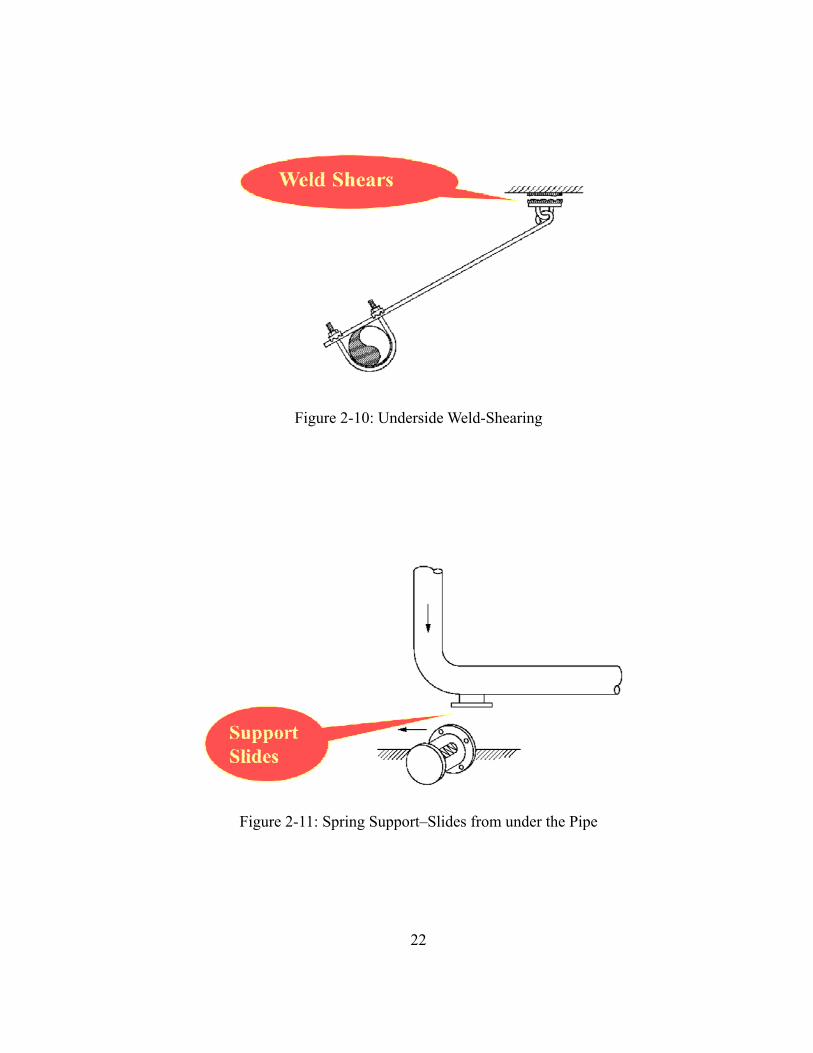
Figure 2-10: Underside Weld-Shearing
Figure 2-11: Spring Support–Slides from under the Pipe

23
1.2.1 THE SAN FERNANDO EARTHQUAKE IN 1971
The 1971 San Fernando earthquake was the turning point in seismic design of
buildings and nonstructural components. Due to the failures observed in this earthquake,
OSHPD started requiring that the hospital buildings remain fully operational following an
earthquake. Figure 2-12 and Figure 2-13 show the failures of piping systems during the
1971 San Fernando Earthquake.
Figure 2-12: Failure of Central Plant Pipe (Gates, 2005)

24
Figure 2-13: Failure of Valve to Piping Connection (Gates, 2005)
1.2.2 THE NORTHRIDGE EARTHQUAKE IN 1994
The1993 Northridge Earthquake resulted in the greatest economic loss to building
structures, highways and bridges in United States history. During the Northridge earthquake,
51 people were killed and over 9,000 people were injured. Major highways collapsed and 9
hospitals were shut-down in Los Angeles area. A total of 2,500 beds were lost for usage in
the hospitals. There were serious damages to nonstructural components, especially the piping
systems. Inside the buildings, water lines were broken, and most hospital buildings suffered
from significant water damage due to failure of water chilled and hot water pipe lines. For
example, the Olive View Hospital had no structural damage, but the hospital was closed
because of water damage (Ayres and Phillips, 1998). Failures were observed in several

25
different piping systems such as HVAC systems, sprinkler piping systems, and water piping
systems. The major reason of the damage to fire sprinkler piping systems has been identified
as the excessive vertical acceleration. Vertical acceleration led to impact of piping with
ceiling and caused the failures in fire sprinkler piping systems. Another reason for significant
damage in sprinkler systems was attributed to bracing type and brace spacing of pipe lines.
Unbraced pipelines less than 1 inch diameter experienced widespread failures (Filiatraul et.
al., 2001). Figure 2-14 illustrates a typical failure of fire sprinkler piping system in the
Northridge Earthquake (Miranda, 2004). Figure 2-15 gives an example of water damage due
to failure of water pipe lines (Miranda, 2004) and Figure 2-16 shows the failure of fire
sprinkler head due to vertical acceleration.
Figure 2-14: Failure of Fire Sprinkler Piping Systems (Miranda, 2004)

26
Figure 2-15: Water Damage due to Failure of Pipe Lines (Miranda, 2004)
Figure 2-16: Failure of Fire Sprinkler due to Vertical Acceleration

27
Besides, according to Fleming (1998), 9 hospitals in the area suffered damage due to water
by failure of fire sprinkler, HVAC, and domestic water systems (Fleming, 1998).
The examples given below describe the failures observed in sprinkler piping systems
(Fleming, 1998).
Cedars-Sinai Medical (0.4g) – Sprinklers on 1-inch lines crossing a seismic
separation on floors 4 through 8 were activated by striking other building
components. (Fleming, 1998).
Holy Cross Medical Center (0.4g) – Short drops (6 to 10 inches long) failed
at threaded Tee-joints (Fleming, 1998).
Santa Monica Hospital Medical Center (0.6g) – 1-inch line failed at a Tee-
joint by impact against a duct. (Fleming, 1998).
1.2.3 THE NISQUALLY EARTHQUAKE IN 2001
The 2001 Nisqually Earthquake was the largest earthquake in the history of the state
of Washington and caused wide spread damage in the Puget Sound area of Washington State.
The Nisqually Earthquake injured about 400 people. Fortunately, there was no fatality
related directly to the earthquake. The economic loss due to nonstructural component
damage was approximately $2 billions. There were also the damage to piping systems such
as the failure of water line and chilled water line on the fourth floor of the Kent Regional
Center (Filiatrault et. al., 2001). During the earthquake, 75-mm diameter of water pipe line
failed at the mechanical room of the roof of a hotel, and the unstable water tank was shifted

28
about 150-mm on the floor. Figure 2-17 shows the ruptured pipe of the supply water line of
the tank in the hotel (Filiatrault et. al., 2001).
Figure 2-17: Failure of Piping System (Filiatrault et. al., 2001)
1.2.4 THE CHILE EARTHQUAKE IN 2010
The 2010 Chile Earthquake of magnitude 8.8 caused severe structural and
nonstructural damage in all type of buildings.
Especially, this strong earthquake influenced most of hospital buildings in central
south region. 4 hospitals were not able to operate and 12 hospitals lost almost 75% function
of the building system. Most of loss in hospitals was caused by damage to nonstructural
components such as suspended ceilings, light fixtures, and fire sprinkler piping system.

29
Figure 2-18 shows that a pipe supporting system became unrestrained from its anchor or
bracing. It moved about 90 degrees and because of this relative motion, the connecting pipes
failed and slipped away from the joint, as shown in Figure 2-19 .
Figure 2-18: Failure of Piping System (Photo: G. Mosqueda, 2010)

30
Figure 2-19: Elbow Failure of Piping System (Photo: G. Mosqueda, 2010)
2. GUIDELINES FOR SEISMIC DESIGN OF FIRE PROTECTION
SPRINKLER PIPING SYSTEM
2.1 NATIONAL FIRE PROTECTION ASSOCIATION (NFPA-13, 2007)
The NBFU-13 (“The National Board of Fire Underwriters for the Installation of
Sprinkler Equipments”) was the first set of guidelines addressing the seismic protection for
fire protection sprinkler piping systems:
The 1950 edition of NFPA-13 contained very few guidelines regarding damage
during earthquakes
31
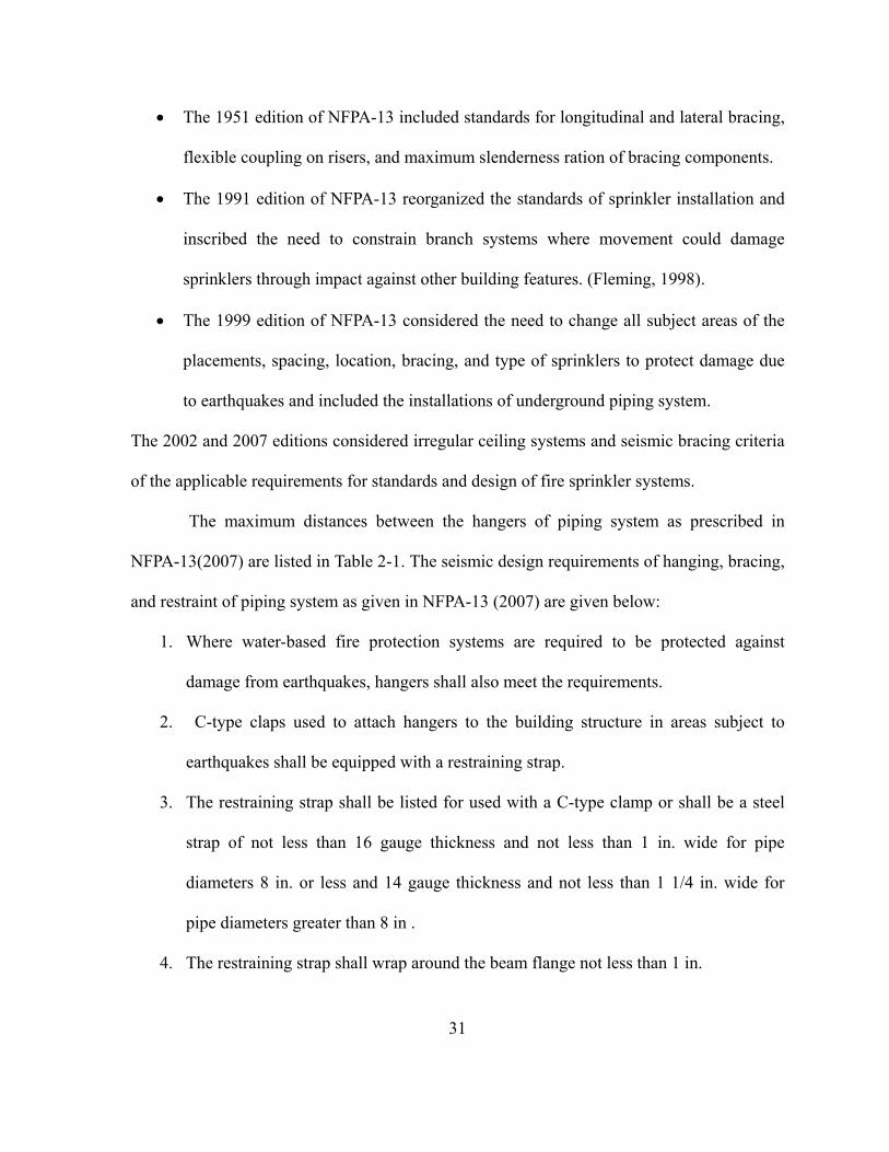
The 1951 edition of NFPA-13 included standards for longitudinal and lateral bracing,
flexible coupling on risers, and maximum slenderness ration of bracing components.
The 1991 edition of NFPA-13 reorganized the standards of sprinkler installation and
inscribed the need to constrain branch systems where movement could damage
sprinklers through impact against other building features. (Fleming, 1998).
The 1999 edition of NFPA-13 considered the need to change all subject areas of the
placements, spacing, location, bracing, and type of sprinklers to protect damage due
to earthquakes and included the installations of underground piping system.
The 2002 and 2007 editions considered irregular ceiling systems and seismic bracing criteria
of the applicable requirements for standards and design of fire sprinkler systems.
The maximum distances between the hangers of piping system as prescribed in
NFPA-13(2007) are listed in Table 2-1. The seismic design requirements of hanging, bracing,
and restraint of piping system as given in NFPA-13 (2007) are given below:
1. Where water-based fire protection systems are required to be protected against
damage from earthquakes, hangers shall also meet the requirements.
2. C-type claps used to attach hangers to the building structure in areas subject to
earthquakes shall be equipped with a restraining strap.
3. The restraining strap shall be listed for used with a C-type clamp or shall be a steel
strap of not less than 16 gauge thickness and not less than 1 in. wide for pipe
diameters 8 in. or less and 14 gauge thickness and not less than 1 1/4 in. wide for
pipe diameters greater than 8 in .
4. The restraining strap shall wrap around the beam flange not less than 1 in.

32
5. A lock nut on a C-type clamp shall not be used as a method of restraint.
6. A lip on a “C” or “Z” purlin shall not be used as method of restraint.
7. Where purlins or beams do not provide an adequate lip to be secured by a restraining
strap, the strap shall be through-bolted or secured by a self-tapping screw.
8. Power-driven fasteners shall not be used to attach braces to the building structure,
unless they are specifically listed for service in resisting lateral loads in areas subject
to earthquakes.
9. In areas where the horizontal force factor exceeds 0.5Wp, power-driven studs shall be
permitted to attach hangers to the building structure where they are specifically listed
for use in areas subject to earthquakes.
10. Longitudinal sway bracing spaced at a maximum of 80ft on center shall be provided
for feed and cross mains.
11. Longitudinal braces shall be allowed to act as lateral braces if they are within 24 in.
of the centerline of the piping braced laterally.
12. The distance between the last brace and the end of the pipe shall not exceed 40 ft.
13. The horizontal force, Fpw, acting on the brace shall be taken as Fpw = CpWp, where Cp
is the seismic coefficient (Table 2-2) utilizing the short period response parameter Ss
obtained from the authority having jurisdiction or from seismic hazard maps.
14. Where the authority having jurisdiction does not specify the horizontal seismic load,
the horizontal seismic force acting on the braces shall be determined as specified
with Cp = 0.5.

33
Table 2-1: Maximum Distance between Hangers (NFPA-13, 2007)
Size (in) 1 1.25 1.5 2 2.5 3 3.5 4 5
Steel (ft) 12 12 15 15 15 15 15 15 15
Threaded light wall steel (ft)
12 12 12 12 12 12 N/A N/A N/A
Copper tube (ft)
8 10 10 12 12 12 15 15 15
CPVC (ft) 6 6-6 7 8 9 10 N/A N/A N/A
Table 2-2: Seismic Coefficient Table (NFPA-13, 2007)
Ss Cp
≤ 0.33 0.31
0.50 0.40
0.75 0.43
0.95 0.50
1.00 0.52
1.25 0.60
1.50 0.71
2.00 0.95
2.40 1.14
3.00 1.43

34
2.2 SHEET METAL AND AIR CONDITIONING CONTRACTOR’S NATIONAL
ASSOCIATION (SMACNA, 2003)
Although, the main hospital structure may not be structurally damaged during an
earthquake, the nonstructural components such as sheet metal ducts, piping, and conduit
systems, equipment etc. are vulnerable to severe damage. Therefore, the nonstructural
systems must be designed to adequately resist the lateral forces during the earthquake.
Following the 1971 San Fernando earthquake, the state of California required that the
hospital buildings remain fully functional during after an earthquake. The California Office
of Statewide Health Planning and Development (OSHPD) approved the design guidelines for
bracing of piping and duct systems as specified by SMACNA in 1976. SMACNA has added
several seismic restraints such as transverse and longitudinal bracing types over the decades.
SMACNA provides the design guidelines and seismic restraint detailing for piping
and duct systems. The bracing types for ducts or piping systems is determined based on the
desired Seismic Hazard Level (SHL). The base seismic coefficient in SMACNA is based on
the 1997 Uniform Building Code (UBC) guidelines and is given p p a p
p p
F a C I
W R
.
Where,
Fp: Seismic Force
Wp: Weight of the Item to be Braced
ap: Component Amplification Factor
35
Ca: Seismic Coefficient
Ip: Occupancy Category
Rp: Component Response Modification Factor
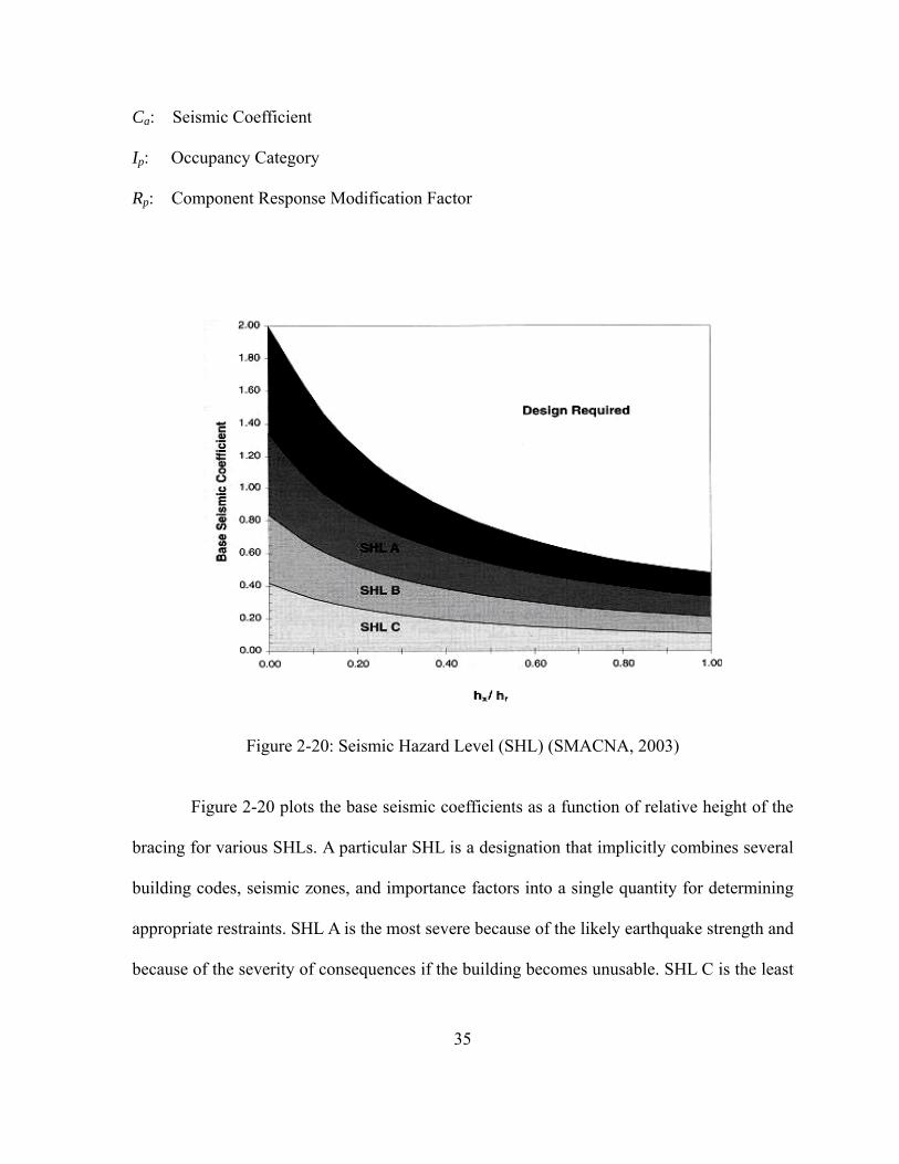
Figure 2-20: Seismic Hazard Level (SHL) (SMACNA, 2003)
Figure 2-20 plots the base seismic coefficients as a function of relative height of the
bracing for various SHLs. A particular SHL is a designation that implicitly combines several
building codes, seismic zones, and importance factors into a single quantity for determining
appropriate restraints. SHL A is the most severe because of the likely earthquake strength and
because of the severity of consequences if the building becomes unusable. SHL C is the least
36
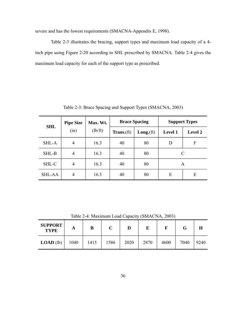
severe and has the lowest requirements (SMACNA-Appendix E, 1998).
Table 2-3 illustrates the bracing, support types and maximum load capacity of a 4-
inch pipe using Figure 2-20 according to SHL prescribed by SMACNA. Table 2-4 gives the
maximum load capacity for each of the support type as prescribed.
Table 2-3: Brace Spacing and Support Types (SMACNA, 2003)
Brace Spacing Support Types SHL
Pipe Size
(in)
Max. Wt.
(lb/ft) Trans.(ft) Long.(ft) Level 1 Level 2
SHL-A 4 16.3 40 80 D F
SHL-B 4 16.3 40 80 C
SHL-C 4 16.3 40 80 A
SHL-AA 4 16.3 40 80 E E
Table 2-4: Maximum Load Capacity (SMACNA, 2003)
SUPPORT TYPE
A B C D E F G H
LOAD (lb) 1040 1415 1586 2020 2870 4600 7040 9240
37
According to Table 2-3 and Table 2-4, the maximum transverse brace spacing for a
4-inch pipe is 40 ft and the maximum longitudinal brace spacing for a 4-inch pipe is 80 ft.
The level 2 represents the critical facilities such as schools and hospital buildings. Therefore,
the maximum load capacities range from 1040 (lb) to 4600 (lb) depending upon the seismic
hazard level (SHL).
3. REVIEW OF EXPERIMENTAL TESTS OF FIRE PROTECTION
PIPING SYSTEMS
3.1 INTRODUCTION
In facilities like the hospitals, the fire sprinkler piping systems are one of the most
critical systems that must continue operating during earthquakes. The locations most
susceptible to damage in these piping components are the joints and support hangers/systems.
The behavior of threaded and grooved joints in the piping are of special interest as leakage
and rupture is generally caused at these points under the actions of extreme lateral loads or
earthquakes.
Therefore, experimental tests have been conducted to study the stiffness and failure modes at
the threaded and grooved joints. Two different tests, based on national standards such as
NFPA-13, were carried out - a) Static Test and b) Dynamic Tests (Antaki and Guzy, 1998).
38
3.2 STATIC TEST OF FIRE PROTECTION PIPING SYSTEMS
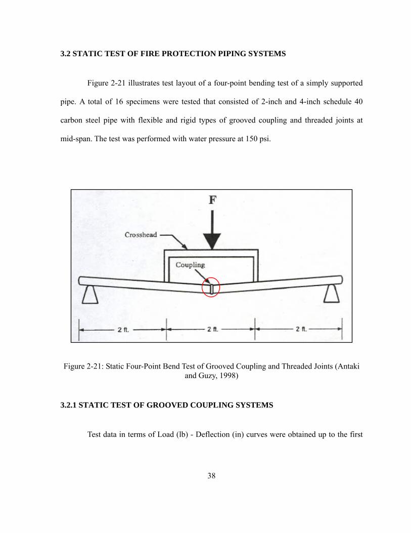
Figure 2-21 illustrates test layout of a four-point bending test of a simply supported
pipe. A total of 16 specimens were tested that consisted of 2-inch and 4-inch schedule 40
carbon steel pipe with flexible and rigid types of grooved coupling and threaded joints at
mid-span. The test was performed with water pressure at 150 psi.
Figure 2-21: Static Four-Point Bend Test of Grooved Coupling and Threaded Joints (Antaki and Guzy, 1998)
3.2.1 STATIC TEST OF GROOVED COUPLING SYSTEMS
Test data in terms of Load (lb) - Deflection (in) curves were obtained up to the first

39
leakage point of the grooved coupling. Different failure modes (major versus minor leaking)
were observed in the 2-inch and 4-inch pipe coupling systems respectively. The 4-inch pipe
coupling system was much stiffer than 2-inch pipe coupling system. However, the 4-inch
pipe coupling system suffered a loss of stiffness upon increase in displacement leading to a
partial fracture occurring at coupling joints (Figure 2-22). Also, the rotations at the coupling
point were significantly larger for flexible coupling of 2-inch and 4-inch grooved coupling
system.
Figure 2-22: Deflection 2-inch Flexible Grooved Coupling (Antaki and Guzy, 1998)

40
Figure 2-23: Load-Deflection 2-inch Rigid Grooved Coupling (Antaki and Guzy, 1998)
Figure 2-24: Load-Deflection 4-inch Flexible Grooved Coupling (Antaki and Guzy, 1998)

41
Figure 2-25: Load-Deflection 4-inch Rigid Grooved Coupling (Antaki and Guzy, 1998)
Figure 2-26: Fracture of 4-inch Grooved Coupling (Antaki, 2004)
Table 2-5 describes the rotational stiffness and moment capacities of flexible and rigid
coupling joint system.

42
Table 2-5: Stiffness and Moment Range of Grooved Coupling (Antaki and Guzy, 1998)
3.2.2 STATIC TEST OF THREADED JOINTS
The static test of threaded joints of 2-inch schedule 40 threaded carbon steel pipe
was conducted in the same manner as grooved coupling. A total of 4 specimens were tested
with threaded joints at mid-span. Figure 2-27 shows the load-deflection curve obtained in
these tests. However, 3 specimens broke down due to rupture at the first exposed thread and
one specimen failed by stripping of the engaged threads (Antaki and Guzy, 1998)
Figure 2-27: Load-Deflection 2-inch Threaded Joints (Antaki and Guzy, 1998)
Stiffness (lb-in / rad)
Moment Capacity (kips-in)
2-inch Rigid or Flexible 1.0×10⁵ to 3.0×10⁵ 12 to 30
4-inch Rigid or Flexible 1.2×10⁶ to 2.4×10⁶ 24 to 96

43
3.2.3 DYNAMIC TEST OF GROOVED COUPLING AND THREADED JOINTS
The dynamic test was conducted to understand the cyclic/seismic performance of
grooved coupling and threaded joint system. A total of 16 grooved coupling joints and 4
threaded joints specimens were tested on a shake table. Each specimen consisted of a 6 foot
long pipe filled with water at 150 psi (same as the static test). The test setup is shown in
Figure 2-28. The excitation level was increased gradually. The leakage of the grooved
coupling was observed at 70% of the capacity and the failure due to bending was similar to
that observed in the static test (Figure 2-29). However, the leakage of the threaded joints
was observed at 50% and 25% of the capacity.
Figure 2-28: Dynamic Test Specimens of the Coupling System and Thread Joints (Antaki and Guzy, 1998)

44
Figure 2-29: Failure Mode of Grooved Coupling by Dynamic Test (Antaki, 2004)

45
REFERENCES
Antaki, G. (2004). “Seismic Capacity of Threaded, Brazed and Grooved Clamped Joints,” ASME 2004, PVP-Vol. 486-1, Seismic Engineering-2004, 135-145 Antaki, G. and Guzy, D. (1998). “Seismic Testing of Grooved and Threaded Fire Protection Joints and Correlation with NFPA Seismic Design Provisions,” ASME 1998, PVP-Vol. 364, Seismic Engineering-1998, 69-75 Ayres, J. M. and Phillips, R. J. (1998). “Water Damage in Hospital Resulting from the Northridge Earthquake,” ASHRAE Transactions Part 1B, SF-98-14-2, 1286-1296 CBC (2001).”California Building Code,” International Conference of Building Officials, Wittier, California Filiatrault, A., Christopoulos, C., and Stearns, C. (2001). “Guidelines, Specifications, and Seismic Performance Characterization of Nonstructural Building Components and Equipment,” PEER Report, 2002/05 Fleming, R. P. (1998). “Analysis of Fire Sprinkler Systems Performance in the Northridge Earthquake,” National Institute of Standards and Technology, NIST-GCR-98-736
Fleming, R. P. (2007). ”The Evolution of Seismic Design of Fire Sprinkler Systems,” National Fire Sprinkler Association, Patterson, NY, 2007
IBC (2000).”International Building Code,” International Code Council, Inc., Falls Church, Virginia
ICBO (1997).”Uniform Building Code,” International Conference of Building Officials, Wittier, California
Lama, P. J. (1998). “Seismic Codes, HAVC Pipe Systems, and Practical Solutions,” ASHRAE Transactions Part 1B, SF-98-14-3, 1297-1304
Miranda, E., Taghavi, S., and Aslani, H. (2003). ”Performance Based Earthquake Engineering for Nonstructural Components,” PEER Annual Meeting Moehle, J. et. al. (2010). “The 27 February 2010 Central South Chile Earthquake: Emerging Research Needs and Opportunities,” EERI, Workshop Report, 2010, http://www.eqclearinghouse.org/20100227-chile/wp-content/uploads/2010/11/Chile-Workshop-Report_FINAL.pdf

46
NFPA-13 (2007). “Standard for the installation of Sprinkler System,” National Fire Protection Association, MA, 2007 Edition SMACNA (2003). “Seismic Restraint Manual Guidelines for Mechanical Systems,” Sheet Metal and Air Conditioning Contractors’ National Association, Inc., 2003 Whittaker, A. S. and Soong, T. T. (2003).”An Overview of Nonstructural Components Research at Three U.S. Earthquake Research Centers,” Proceedings of Seminar on Seismic Design, Performance, and Retrofit of Nonstructural Components in Critical Facilities, ATC-29-2, Newport Beach, California

47
PART III
FRAGILITY ANALYSIS OF THREADED TEE-JOINT
CONNECTIONS IN HOSPITAL PIPING SYSTEMS
Bu Seog Ju, Sashi Kanth Tadinada, and Abhinav Gupta

48
FRAGILITY ANALYSIS OF THREADED TEE-JOINT CONNECTIONS IN HOSPITAL PIPING SYSTEMS
Bu Seog Ju, Sashi Kanth Tadinada, and Abhinav Gupta
ABSTRACT
The cost of damage to the non-structural systems in critical facilities like nuclear
power plants and hospitals can exceed 80% of the total cost of damage during an earthquake.
Studies assessing damage from the 1974 San Fernando and 1994 Northridge earthquakes
reported a widespread failure of non-structural components like sprinkler piping systems
(Ayer and Phillips, 1998). The failure of piping systems led to leakage of water and
subsequent shut-down of hospitals immediately after the event. Consequently, probabilistic
seismic fragility studies for these types of structural configurations have become necessary to
mitigate the risk and to achieve reliable designs.
This paper proposes a methodology to evaluate seismic fragility of threaded Tee-
joint connections found in typical hospital floor piping systems. Numerous experiments on
threaded Tee-joints of various sizes subjected to monotonic and cyclic loading conducted at
University of Buffalo indicate that the "First Leak" damage state is observed predominantly
due to excessive flexural deformations at the Tee-joint section. The results of the monotonic
and cyclic loading tests help us evaluate the following characteristics for a given pipe size
and material:
(i) Maximum allowable value of rotational deformation at the Tee-joint section to prevent

49
"First Leak" damage state
(ii) The force-displacement and moment-rotation relationships at the Tee-joint section
A non-linear finite element model for the Tee-joint system is formulated and
validated with the experimental results. It is shown that the Tee-joint section can be
satisfactorily modeled using non-linear rotational springs. The system-level fragility of the
complete piping system corresponding to the “First Leak” damage state is determined from
multiple time-history analyses using a Monte-Carlo simulation accounting for uncertainties
in demand.

50
1. INTRODUCTION
The total installation and construction cost of non-structural elements in any critical
facility like a hospital or a nuclear power plant is almost 80% of the total cost (Ritherman,
2009). Furthermore, damage to the non-structural systems in hospitals comprise a significant
proportion of the total economic loss incurred in the event of an earthquake. During the 1994
Northridge earthquake, 85% of the total $7.4 billion damage is attributed to non-structural
systems (Kircher, 2003). The Olive View Hospital had to be shut down soon after the 1994
Northridge earthquake due to water damage caused by failure of sprinkler systems (Ayer &
Phillips, 1998). Similarly, during the 1971 San Fernando earthquake, 4 of 11 medical
facilities in the area incurred significant economic losses due to damaged non-structural
components (Wasilewski, 1998). Damage to components such as fire protection piping
system, Heating, Ventilating, and Air Conditioning (HVAC), and water piping systems have
resulted in direct economic loss and injuries or loss of life in many seismic events.
In recent years, many engineers have recognized the need to address the problem in
the design stages such that the nonstructural components remain operational or functional
after an earthquake. Antaki and Guzy (1998) conducted static and dynamic tests of the fire
protection piping systems designed in accordance with National Fire Protection Association
(NFPA-13). The objective of tests was to identify the stiffness, failure modes, and limit states
for leakage of threaded pipe joints and grooved coupling systems that are commonly used in
the piping systems. ATC-58 (2004) has highlighted the need for a performance-based design
based on statistical approaches in nonstructural systems. Consequently, probabilistic seismic

51
fragility studies for these systems can be vital in mitigating risk and achieving reliable
designs.
A fragility curve describes the relationship between a ground motion intensity
parameter like Peak Ground Acceleration (PGA) and the corresponding probability of failure
as characterized by a specified limit-state or exceedence criteria. The concept of fragility has
been used extensively for over more than a decade in the seismic probabilistic risk
assessment of nuclear power plant structural and nonstructural systems. In the nuclear power
plant industry, the most commonly used approach to evaluate structural fragilities is the
lognormal model based on design factors of safety (Kennedy et al, 1980; EPRI, 1994) which
assumes a lognormal distribution for the acceleration capacity of the structure. The
“acceleration capacity” of a structure is defined by the level of PGA that the structure can
safely withstand without any damage and is equal to the Design Basis Earthquake (DBE)
level of PGA multiplied by a Capacity Factor (Fc). The median and the logarithmic standard
deviations of Fc are calculated from design code equations, past studies, experience data and
to quite an extent on expert judgment.
The widely used lognormal model of structural fragility cannot be directly extended
to the piping and secondary systems due to the lack of sufficient existing fragility data.
Furthermore, characterization of the structural performance in terms of an “acceleration
capacity” is quite simplistic and in many cases far from the “true performance” especially as
the higher mode effects and mass interaction with the supporting structure tends to be
significant in piping systems. Many researchers have evaluated seismic fragilities using
experimental data either independently or in conjunction with experimentally validated finite

52
element models (Lupoi et al, 2006). Consideration of experimental data is essential in a
fragility assessment primarily for the purpose of characterizing the structural performance in
terms of an appropriate “limit-state”. Almost all the studies have focused on evaluating the
seismic fragilities of structural components or sub-systems. Limitations in conducting large-
scale experiments are a key obstacle in the evaluation of system-level fragilities. This is
particularly true in the case of piping-systems.
In this paper, we present the results of a detailed study that focuses on:
Characterizing the performance “limit-state” of threaded Tee-joints in a fire sprinkler
piping system using experimental results from monotonic and cyclic testing of Tee-
joint components.
Developing an equivalent non-linear finite element model of the Tee-joint component
such that the results reconcile with the experimentally observed behavior.
Incorporating the non-linear Tee-joint model in an actual hospital piping system
model for the purpose of conducting a system level analysis and evaluate system level
fragilities.
Evaluating system-level fragilities for failure at different locations of the same Tee-
joint component within the piping system.
Often, it is suggested that the excessive computational effort needed in a non-linear
system-level analysis can be reduced by using linear analysis of the piping system to
evaluate earthquake input at the location of the Tee-joint. Then, conduct a separate
53
(decoupled) non-linear analysis of the Tee-joint to determine the fragility. In this
study, we compare the fragility evaluated from a system-level analysis with that
evaluated from the corresponding decoupled analysis of the non-linear Tee-joint.
2. DESCRIPTION OF EXPERIMENTAL TESTS OF THREADED TEE-
JOINT
Many assemblies and sub-assemblies in piping systems like connections and
linkages often exhibit complex nonlinear behavior that is quite difficult to model or predict
using simple finite element models. An accurate FE model for a connection like a threaded
piping joint often requires dense meshing using special contact elements thus making the
problem computationally ineffective for fragility estimations. In such cases, simple
monotonic and cyclic tests can provide valuable insights into the behavior of these
connections and their typical damage states. Data from such tests can also help us formulate
simpler but experimentally validated nonlinear finite element models that describe the
seismic response of the connections with sufficient accuracy.
Laboratory tests were conducted by University at Buffalo, State University of New
York (UB) on various kinds of Tee-joint component of sprinkler piping systems (Dow, 2010).
Both, monotonic as well as cyclic loading were considered. Two types of piping material,
Black Iron and CPVC, were considered. A total of three different diameter pipe components,
2 inch, 1 inch and ¾ inch, were included. In this paper, a detailed discussion is provided on
the experimental setup and results for only the 2 inch diameter Black Iron threaded piping

54
Tee-joint.
Figure 3-1 shows the actual test set-up for determining the force-displacement and
moment-rotation relationships of the threaded Tee-joint connection under monotonic and
cyclic loading conditions. Figure 3-1 also gives the schematic of this setup along with the
direction of loading and the measurement locations. As seen in this figure, the loading was
applied as an in-plane force loading at the bottom of the Tee-joint. The test-setup was
erected in such a way that the Tee-joint can be displaced in both forward and reverse
directions along the “bottom of the T”, an axis perpendicular to the center of the Tee-joint, as
shown in Figure 3-1. Also, the ends of the pipes connected to the flange of the Tee-joint were
simply supported. The failure was characterized in terms of “first-leakage” and if observed in
terms of “pipe-fracture.” To detect the “first-leakage” point, the piping component
arrangement was connected to a water hose that carried water at standard city pressure. Also,
ten potentiometers were used to record the data. One monotonic test and three cyclic tests
were conducted for each type of piping component (Dow, 2010).
Figure 3-2 gives the force-displacement curve as measured in the case of monotonic
loading test. The “first-leakage” point is depicted by the vertical line at 1.5189 inch
displacement. As seen in this figure, a leakage caused a vertical drop in the force-
displacement curve at this value of displacement. The moment-rotation curves as measured at
the two flanges, right and left ends, are shown in Figure 3-3 and 3-4. As in the case of force-
displacement curve, the moment-rotation curve at the right-end of the Tee-joint flange also
exhibits a vertical drop in Figure 3-3 at the first-leakage, corresponding to a rotation of
0.0814 radians. However, Figure 3-4 for the moment-rotation curve at the left-end of the Tee-

55
joint flange does not exhibit a similar vertical drop. The rotation corresponding to the first-
leakage point is identified in this curve by a vertical line. This difference between the left-end
and the right-end behavior exists because the first-leakage occurred at the right-end as shown
in Figure 3-5. The reasons for the first-leakage are identified as bending of pipe ends and the
corresponding slippage and rupture of pipe threads.
The same setup was used to conduct three different cyclic loading tests for each type
of Tee-joint. The loading protocol used in these tests is shown in Figure 3-6. The
corresponding force-displacement and moment-rotation curves are shown in Figure 3-7 to 3-
9. The first-leakage points are also shown on these figures. It can be observed that the Tee-
joint undergoes several cycles before accumulating enough rotations that cause a leakage.
Table 3-1 lists the moments and rotations at the instance of “First Leak” damage state in the
three cyclic tests of 2 inch Black Iron piping Tee-joint. It must be noted that the first-leakage
was detected in cyclic tests at rotations in the range of 0.014 - 0.017 radians which are much
smaller than the corresponding first-leakage detected in monotonic tests at rotations of 0.07 -
0.08 radians. This data implies that the behavior of the threaded connection under cyclic
loading is more critical than that under monotonic loading. Next, we use the experimental
data and observations to identify an engineering demand parameter that is subsequently used
to characterize the performance of threaded Tee-joint in terms of a limit-state corresponding
to first-leakage.

56
3. DEFINITION OF THE “FIRST LEAKAGE” LIMIT STATE
In order to evaluate the structural fragility, it is necessary to characterize the
performance of a structural component or system in terms of a limit state. The limit-state is
representative of a formal criterion corresponding to the observed failure/damage. Based on
the experimental results discussed above, it can be identified that rotations at the flanges of
the Tee-joint as observed from the cyclic tests are a good choice for engineering demand
parameter to characterize the limit-state corresponding to the first-leakage instance. While
the test data provides a good insight into the absolute values of rotations corresponding to
first-leakage instance for a 2-inch diameter Black Iron pipe, it is not prudent to use these
values (or a distribution derived from these values) for characterizing the capacity because
the absolute values are likely to change significantly due to changes in material and/or
geometrical properties of the threaded Tee-joint. For example, relatively smaller changes in
the initial stiffness (slope of the moment-rotation curve) can result in a relatively larger
variation in absolute value of rotations corresponding to the first leakage. Therefore, it is
necessary to characterize the performance of the Tee-joint using a limit-state that can
represent the behavior in a more general form. To do so, we compare the experimental results
presented above with the criterion that forms the basis of design guidelines specified in the
ASME (2004) for nuclear power plant piping systems. It must be noted that unlike the piping
system in hospitals and office buildings that have threaded joints, the studies related to
nuclear power plant piping systems are conducted on piping systems that have welded joints.
ASME (2004) Boiler Pressure Vessel and Piping Code characterizes the performance

57
of a piping component such as a pipe-bend (elbow) or a Tee-joint in terms of a “Plastic
Collapse” moment. The “Plastic Collapse” moment is calculated from the moment-rotation
curve as shown in Figure 3-10. It is defined as the ordinate where a straight line drawn at an
angle of with respect to the moment-axis intersects the moment-rotation curve. Angle
is defined as the initial slope of the moment-rotation curve with respect to the moment-axis.
The ASME design equations use this definition of “Plastic Collapse” moment to characterize
the performance in terms of the moment limit-state (not a rotation based limit state). The
intent behind the definition of a limit state based on moment capacity is to design for safety
against the formation of a plastic hinge. Since the pipe joints in the nuclear power plant
piping are welded, safety against the formation of a plastic hinge is the primary objective. On
the contrary, safety against “leakage” is the primary objective in a threaded pipe joint of the
types encountered in hospital and office building piping systems.
Next, we compare the “first-leakage” rotations recorded in the experimental test of
threaded Tee-joints (given in Table 3-1) with the ASME definition of the failure point on the
moment-rotation curve. Figure 3-11 plots the 3 first-leakage rotations from the 3 cyclic
loading tests along with the moment-rotation relationship observed at the left end of the Tee-
joint. Interestingly, all the 3 “first-leakage rotations” lie between the lines 2 and
5.2 where is the initial slope with respect to the moment-axis. This observation
leads us to believe that the ASME criteria can be used in an alternative way, i.e. the “first-
leakage” failure can be conservatively characterized in terms of a limiting rotation which
corresponds to a point on the moment-rotation curve where the 2 line intersects the

58
moment-rotation curve. In fact, the argument can be extended further to characterize failure
limit-states for more severe damage states. For example, one may argue that if 2
represents minor damage (“first leakage”) then a larger rotation limit-state such as 3
represents severe damage. While there is no experimental basis, in this paper we consider
two additional limit states simply for illustration purposes. We consider 5.2 to
characterize “moderate damage” and 3 to characterize “severe damage”. The purpose
of considering these additional limit states is to evaluate the relative changes in fragility
curves for these three limit-states. Next, we discuss the details of the nonlinear finite element
model that is created to represent the nonlinear behavior of this Tee-joint pipe component and
to include it in the model of the complete piping system.
4. FINITE ELEMENT MODEL, VERIFICATION, AND FRAGILITY
ESTIMATION
In order to calculate the fragility of the complete piping system (system-level
fragility), it is necessary to create a nonlinear finite element model of the Tee-joint and
incorporate it in the model of the complete piping system. Furthermore, the finite element
model must reconcile with the results obtained from the experimental tests. Often,
researchers create detailed finite element models with dense meshing and contact elements to
reproduce the behavior observed in test data. Such a model while accurate can be
computationally impractical for incorporation into a system-level piping analysis especially

59
if multiple locations in the piping system can have the non-linear Tee-joint. Therefore, we
developed a simple model of the Tee-joint as shown in Figure 3-12. In this model, we
incorporate two non-linear rotational springs whose characteristics are specified based on the
moment-rotations relationship observed in the test data. The branch pipes connected to the
either side of the flanges are supported by a hinge at the end to allow rotations at the end. The
loads are applied as an axial load at the bottom of the Tee-joint for cyclic and monotonic tests,
respectively, as shown in Figure 3-6 and Figure 3-13.
Figure 3-14 compares the moment-rotation curves at the location of rotational
springs from finite element model to that obtained from the experimental tests for the
monotonic load case. As seen in the figure, the two sets of curves are almost identical until
the point of failure i.e. first leakage.
As we can see from Figure 3-11 and Table 3-1, the first leak failure rotations from
monotonic and cyclic tests are significantly different. In order to evaluate the seismic
fragility of the Tee-joint connection, it is necessary to use the finite element model that is
validated with the more critical loading tests, i.e. the cyclic tests. Next, we obtain the
nonlinear moment-rotation relationships of the two rotational springs used in the finite
element model for the cyclic load case.
Detailed analysis of the moment- rotation curve observed indicates a gradual
degradation of stiffness in all cyclic tests. In order to characterize the hysteretic behavior of
the Tee-joint under cyclic loading, the "Pinching4" material model from the OpenSees Finite
Element Package (Mazzoni et al, 2006) was used. The "Pinching4" material of OpenSees
models a uniaxial material that represents a "pinched" load-deformation response and
60
exhibits degradation under cyclic loading. The strength and stiffness degradation properties
are prescribed in the "Pinching4"model using a set of parameters denoting stiffness
degradation, reloading stiffness degradation and strength degradation. Figure 3-15 shows a
schematic definition of the OpenSees Pinching4 Uniaxial Material Model. Figure 3-16
compares the moment-rotation relationship of the left spring between Pinching4 model
simulation with the experimental test under the cyclic loading given in Figure 3-6.
Next, we present the details of the piping system model. The representative piping
system considered in this study is an actual fire sprinkler piping system taken from a hospital
in California. The hospital piping system shown in Figure 3-17 consists of main piping runs
along 4 sections with a total of 64 branches in all. The main runs of the piping system
comprise of 2-inch and 4-inch diameter pipes whereas the branches comprise of pipes with
diameters smaller than those of the main pipe runs. This system is supported by unbraced
single hangers, transverse braced hangers and longitudinal braced hangers at various
locations. The details of actual support locations are not provided in this paper for brevity.
There are 4 anchors at the ends of the four main piping system runs. Since all the supports of
the piping system are connected to the same ceiling, they all experience the same earthquake
input. The natural frequencies for this piping system for the first 8 modes are given in Table
3-3. Ideally, the earthquake input exhibited by the piping through its supports is an amplified
earthquake motion filtered through the building to which the piping is connected. Typically,
the amplification is higher on higher floors and the filtering changes the characteristic of
earthquake motion. The degree of amplification and nature of modification due to filtering in
a time history is different for different buildings which cannot be generalized. Therefore in

61
this study, we consider free-field earthquake ground motions applied directly to piping
supports. This situation is representative of a piping system in low rise buildings (less than 4
or 5 stories tall). The effect of building’s own characteristics and its interaction with the
piping system introduces additional complexities which are not considered in this paper. The
effects of these building characteristics on the piping fragility can be considered after the
preliminary study presented in this paper is completed. Therefore, the results presented in
this paper are quite valuable for piping systems in low rise buildings including hospitals,
office spaces, hotels, schools, etc.
Nonstructural fragilities are functions that relate the probability that a nonstructural
component will exceed a certain limit-state as a function of the Engineering Demand
Parameter (EDP) (Bachman et. al., 2004). Equation (1) gives the expression for fragility at a
Peak Ground Acceleration (PGA) level of .
PGAPPf |lim (1)
The structural fragility is usually estimated empirically by conducting multiple
nonlinear time history analyses of the structure for various ground motions
N
PGAP
N
ii
f
1
lim, |1
(2)
In equation (2), ,i is the maximum rotation from ith earthquake time history analysis at a
PGA level of and 1(.) is the indicator function.
Next, we present a detailed discussion on the results for evaluating the system-level

62
fragility of the sprinkler system for failure at the location of a 2 inch Black Iron threaded
Tee-joint.
5. RESULTS: SYSTEM FRAGILITY USING VALIDATED FE
MODEL FOR MONOTONIC LOAD CASE
To begin with, we calculate fragility at the location of 2-inch Black Iron threaded
Tee-joint(s) by incorporating the experimentally validated FE model for monotonic load case
as discussed in section 4 above. Since monotonic load case gives moment-rotation curve for
only loading path and does not provide the behavior for unloading path, we use the widely
accepted practice in which the same moment-rotation curve is used for loading as well as
unloading conditions.
5.1 FAILURE AT SINGLE LOCATION
In order to study the system-level fragility for the complete piping system, we begin
with a simple case in which the moment-rotation non-linearity in the threaded Tee-joint
connection is considered at only a single critical location in the complete piping system, i.e. a
single location is considered for failure within the piping system. The complexity of multiple
failure locations is introduced later and discussed in subsequent sections in this manuscript.
Figure 3-18 shows the configuration of the system considered. In Figure 3-18, the main
piping system from Figure 3-17 is modeled and the non-linear threaded Tee-joint connection

63
is a part of the 2 inch branch piping sprinkler system as shown. The particular location of the
2 inch branch piping sprinkler system shown in the figure is selected for detailed fragility
evaluation based the results from a linear time history analysis of the complete piping, i.e. the
critical location is determined as the point of maximum displacements and rotations from
linear time history analyses on the main piping.
The first mode frequency of the complete piping system is 1.82 Hz. A total of 75 real
earthquake records normalized to the same PGA, (Gupta and Choi, 2005) are chosen to
model the uncertainty in ground motion. Table 3-4 list the earthquake records considered in
this study. Non-linear analyses were conducted by normalizing each of the 75 earthquake
records at many PGA levels from 0.5g to 3.0g at an interval of 0.1g and the fragility was
estimated at each PGA level using Equation (2). The fragility curves corresponding to the
three damage states specified in Table 3-2 are given in Figure 3-19. As seen in this figure, the
piping system is relatively more fragile for the case of 2 and the fragility curve shifts to
the right (less fragile) for the other two limit states of 2.5 and 3 .
5.2 FAILURE AT MULTIPLE LOCATIOINS
After calculating the preliminary fragility estimates for the case of failure at single
location, we introduce the possibility of failure at two locations. The second location is also
selected in a similar manner as before, i.e. the location of a 2-inch threaded Tee-joint that has
the next largest displacements and rotations as observed from the linear analysis as well as
from the non-linear analysis with a single non-linear Tee-joint. The purpose is to study

64
whether the fragility curves calculated in the previous section exhibit any change due to the
presence of additional non-linearity in the piping system. A related objective is to evaluate
the relative difference in the fragility curves for failure at the two locations. The two critical
nonlinear Tee-joint locations where failure is considered to be possible in this study are
shown in Figure 3-20. The same set of earthquake records are considered as before. The
system fragility curves for the case of first-leakage limit state ( 2 ) at locations 1 and 2
are shown in Figure 3-21, respectively. It can be seen that the fragility curve for failure at
Location 1 remains unchanged from that shown in Figure 3-21. This indicates that the
presence of additional non-linearity at the second most critical location in the piping system
does not have any meaningful effect on the fragility estimate for failure at Location 1.
Furthermore, it can be seen that the probability of failure at location 1 is about 20 percent
greater than the probability of failure at location 2 throughout the range of PGA values of
interest.
Finally, we introduce additional complexity by considering the possibility of failure
at a third location in the piping system. One may argue that it might be more productive to
introduce non-linearity at all possible threaded Tee-joint locations. However, it must be noted
that greater locations of non-linearity increases the computation time for a single time-history
analysis significantly. The total computational effort needed to conduct 75 time histories at
each level of PGA is non-trivial. Therefore, we consider only 3 locations for possible failure
in the piping system as shown in Figure 3-22. The system-level fragilities for failure at all the
three locations are shown in Figure 3-23. It can be seen that the fragility curves for failures at
locations 1 and 2 remain unchanged. In fact, failure at location 3 is not initiated until PGA

65
value of 4.8g which is much larger than the PGA value of about 3g where the fragility curve
for both locations 1 and 2 reached a probability of failure equal to unity. Therefore, it can be
concluded that failure at a third or additional location does not necessarily need to be
considered in the estimation of system-level piping fragility.
5.3 EFFECT OF STRENGTHENING AT LOCATION 1
Often, it is desired that the “most-probable” failure location identified in a fragility
analysis be strengthened/retrofitted for improved seismic performance. The purpose of this
task is to evaluate the effect of such strengthening on the changes in the fragility associated
with failures at other possible locations. As shown in Figure 3-24, the piping system model
with non-linearity at two locations is considered but modified such that the threaded Tee-
joint connection at location 1 is assumed to remain linear. The system-level fragility at
location 2 as shown in Figure 3-25 modified by strengthening at location 1 remains
unchanged. The reason for this observation was investigated further. As shown Figure 3-26
the fundamental mode shape of the piping system does not excite the complete piping system
but a localized region around the Tee-joint at location 1. Similarly, the response at location 2
is governed by a localized mode at that location which is the second mode of the piping
system as shown in Figure 3-27. Therefore, the response at a particular location in a piping
system is typically governed by a local mode and not a global mode shape and hence the
observation that strengthening at location 1 does not alter the fragility associated with failure
at location 2.

66
6. SEISMIC FRAGILITY OF THE THREADED TEE-JOINT AT
LOCATION-1 BASED ON CYCLIC FE MODEL
Next, we consider the non-linear FE model of the Tee-joint for which the moment
rotation curve is reconciled with the results obtained from the cyclic tests, i.e. using the
nonlinear model described earlier in section 4. The purpose is to evaluate the change, if any,
in fragility curves due to consideration of validated FE models based on monotonic test
versus those based on cyclic test. No other change was made and the same input earthquake
records are considered. The system-level fragility curves corresponding to the three damage
states at location 1 are given Figure 3-28. Furthermore, Figure 3-29 compares the fragility
curve for “first-leakage” case obtained from this analysis with that obtained from the
previous analysis for the monotonic test case. It can be seen that the fragility curves
evaluated using FE model validated using the monotonic tests give higher fragility estimates.
These differences can have a meaningful impact on the design of a piping system. The
primary reason for this difference is the degree of stiffness degradation and energy
dissipation in each cycle for the two different cases of moment-rotation curves. It may be
argued that an FE model validated using cyclic test results gives more realistic estimates of
fragility curves. For the case of multiple failure locations, the fragility curves are given in
Figure 3-30. The natures of differences are similar to those observed in earlier case. The
fragilities at both locations are much lower in the case of FE model validated for cyclic test
data when compared to the corresponding fragilities at the two locations in the case of FE
model validated for monotonic test data as is given in Figure 3-21.
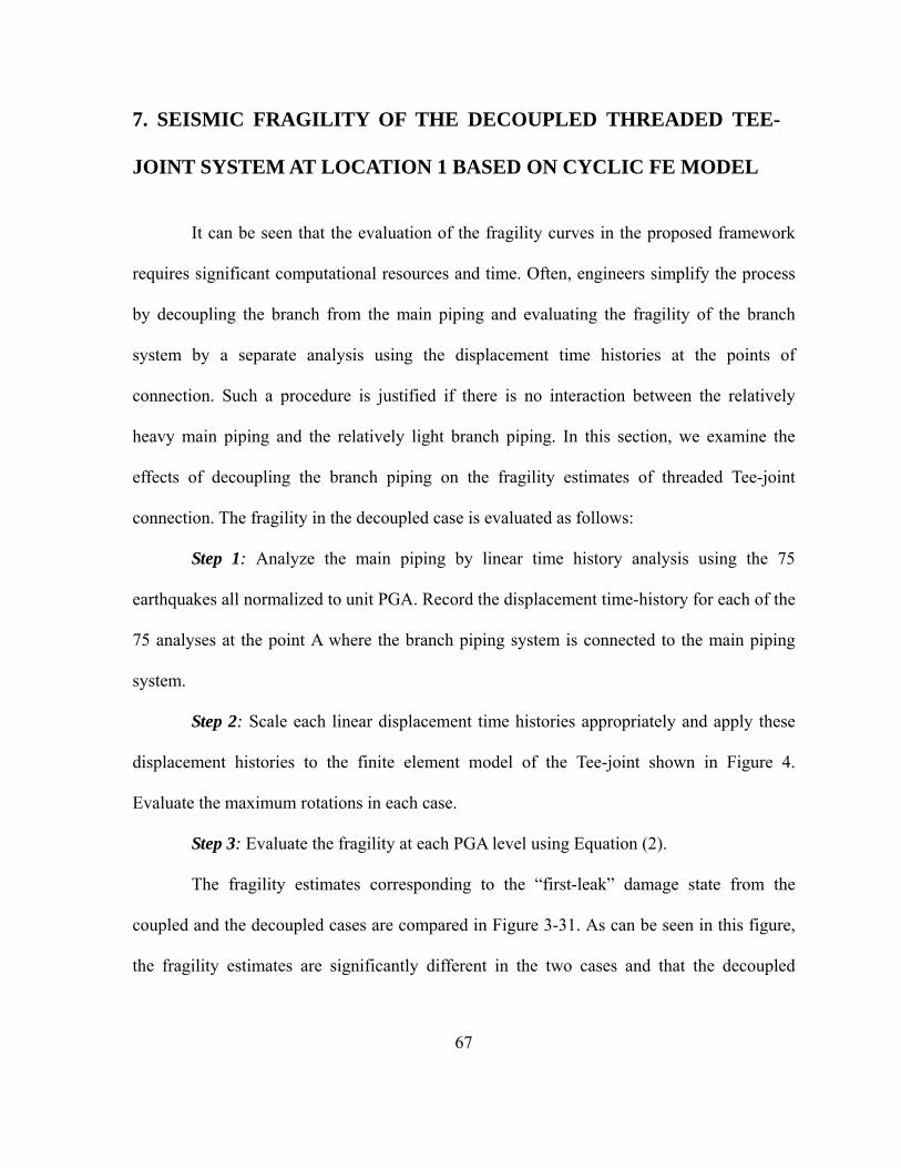
67
7. SEISMIC FRAGILITY OF THE DECOUPLED THREADED TEE-
JOINT SYSTEM AT LOCATION 1 BASED ON CYCLIC FE MODEL
It can be seen that the evaluation of the fragility curves in the proposed framework
requires significant computational resources and time. Often, engineers simplify the process
by decoupling the branch from the main piping and evaluating the fragility of the branch
system by a separate analysis using the displacement time histories at the points of
connection. Such a procedure is justified if there is no interaction between the relatively
heavy main piping and the relatively light branch piping. In this section, we examine the
effects of decoupling the branch piping on the fragility estimates of threaded Tee-joint
connection. The fragility in the decoupled case is evaluated as follows:
Step 1: Analyze the main piping by linear time history analysis using the 75
earthquakes all normalized to unit PGA. Record the displacement time-history for each of the
75 analyses at the point A where the branch piping system is connected to the main piping
system.
Step 2: Scale each linear displacement time histories appropriately and apply these
displacement histories to the finite element model of the Tee-joint shown in Figure 4.
Evaluate the maximum rotations in each case.
Step 3: Evaluate the fragility at each PGA level using Equation (2).
The fragility estimates corresponding to the “first-leak” damage state from the
coupled and the decoupled cases are compared in Figure 3-31. As can be seen in this figure,
the fragility estimates are significantly different in the two cases and that the decoupled
68
analysis yields highly conservative fragility values i.e. predicts the system to be more fragile.
The primary reason for the differences in the two curves is that there exists a mass interaction
and tuning between the main and branch piping systems. Ignoring these effects, leads to an
incorrect estimation of the fragility.
8. SUMMARY AND CONCLUSIONS
The cost of damage to the non-structural systems and components can exceed 80%
of the total damages during an earthquake. Many existing studies and ATC-58 (2004)
highlight the need for performance based design and probabilistic approaches to mitigate risk
and to achieve reliable designs. This paper focuses on evaluating the structural seismic
fragilities of threaded T- joint connection in sprinkler piping systems.
Often, threaded connections in piping tend to exhibit complex nonlinear behavior
under dynamic loading. Simple laboratory tests of the threaded connections under monotonic
and cyclic loading can give us insights into the behavior and the typical damage patterns.
Test data can be used to define the limit states of damage as well as obtain nonlinear force-
displacement and moment-rotation relationships at locations around the connection. This can
be used to create a relatively simple non-linear finite element model for seismic fragility
evaluations.
The University at Buffalo, SUNY conducted laboratory tests on various Tee-joint
components of sprinkler piping systems. The tests indicate that the "First Leak" damage state
is observed predominantly due to excessive flexural deformations at the Tee-joint section. We

69
use the monotonic and cyclic loading test data to characterize the limit state corresponding to
“First Leak” for a 2 inch black iron threaded Tee-joint connection and to develop a simple
nonlinear finite element model describing the Tee-joint behavior.
The nonlinear FE model developed is then used in conjunction with the main line of
a typical hospital floor piping to obtain system-level fragilities corresponding to the first leak
damage state. A total of 75 real normalized earthquake records are used to describe the
uncertainty in ground motion histories. In addition, the system fragility is evaluated by
considering two different types of threaded Tee-joint connections i.e. monotonic FE model
and cyclic FE model. The fragility curves are generated for failure at a single critical location
as well as multiple possible failure locations. The seismic fragility curves of the Tee-joint
system at each location are significantly different for the two different FE models considered.
Consequently, it is suggested that the threaded Tee-joint connection based on cyclic FE
model be used to evaluate the system-level fragility at each critical location.
It is also illustrated that the system fragilities corresponding to the same limit state is
significantly different when evaluated from a decoupled analysis of just the Tee-joint
assembly component. Therefore, mass interaction and tuning between the main line piping
and the branch piping can have a considerable effect on seismic fragilities.

70
ACKNOWLEDGEMENTS
This research was partially supported by the NEES Nonstructural Project (NSF) and the
Center for Nuclear Power Plant Structures, Equipment and Piping at North Carolina State
University. Resource for the Center come from sponsoring industrial organizations,
National Science Foundation, the Civil Engineering Department, and College of Engineering
in the University.

71
REFERENCES
Antaki, G. (2004). “Seismic Capacity of Threaded, Brazed and Grooved Clamped Joints,” ASME 2004, PVP-Vol. 486-1, Seismic Engineering, 135-145 Antaki, G. and Guzy, D. (1998). “Seismic Testing of Grooved and Threaded Fire Protection Joints and Correlation with NFPA Seismic Design Provisions,” ASME 1998, PVP-Vol. 364, Seismic Engineering, 69-75 ASME (2004), “Rule for Construction of Nuclear Facility Components,” ASME Boiler and Pressure Vessel Code, Section III, American Society of Mechanical Engineers Ayres, J. M. and Phillips, R. J. (1998). “Water Damage in Hospital Resulting from the Northridge Earthquake,” ASHRAE Transactions Part 1B, SF-98-14-2, 1286-1296 Bachman, R. (2003).”Engineering Demand Parameters (EDPs) for Nonstructural Components,” PEER Annual Meeting Bachman, R., Bonowitz, D., Caldwell, P. J., Filiatrault, A., Kennedy, R. P., McGavin, G., and Miranda, E. (2004). “Engineering Demand Parameters for Nonstructural Components,” ATC-58 Project Task Report-ATC, Redwood City, California Dow, J. (2010). “Testing and Analysis of Iron and Plastic Tee-joint in Sprinkler Systems,” NEESR-GC: “Simulation of the Seismic Performance of Nonstructural Systems,” http://nees.org/site/oldnees/filedir_2/REU 2009_Dow_Paper.pdf Electric Power Research Institute (EPRI) (1994). “Methodology for Developing Seismic Fragilities,” EPRI TR-103959 (Principal Investigators: Reed, J.W. and Kennedy, R.P.), Electric Power Research Institute, Palo Alto, California Fleming, R. P. (1998). “Analysis of Fire Sprinkler Systems Performance in the Northridge Earthquake,” National Institute of Standards and Technology, NIST-GCR-98-736 Fleming, R. P. (2007). “The Evolution of Seismic Design of Fire Sprinkler Systems,” National Fire Sprinkler Association, Patterson, NY, 2007 Gerdeen, J. C. (1979). “A Critical Evaluation of Plastic Behavior Data and A United Definition of Plastic Loads for Pressure Components,” Welding Research Council (WRC) Bulletin 254 Kennedy, R. P., Cornell, C.A., Campbell, R. D., Kaplan, S., and Perla, H.F. (1980).

72
“Probabilistic Seismic Safety of an Existing Nuclear Power Plant,” Nuclear Engineering and Design, 59, 315-338 Kircher, C. A. (2003). “It Makes Dollars and Sense to Improve Nonstructural System Performance,” Proceedings of Seminar on Seismic Design, Performance, and Retrofit of Nonstructural Components in Critical Facilities, ATC-29-2, Newport Beach, California Mazzoni, S., Mckenna, F., Scott, M. H., Fenves, G. L., and et al. (2006). “OpenSees Command Language Manual,” Open System for Earthquake Engineering Simulation (OpenSees), http://opensees. berkeley.edu/ NFPA-13 (2007). “Standard for the installation of Sprinkler System,” National Fire Protection Association, MA, 2007 Edition Lupoi, G., Franchin, P., Lupoi, A., Pinto, P. E. (2006). “Seismic Fragility Analysis of Structural Systems,” Journal of Engineering Mechanics, ASCE, 4-385-395 Reitherman, R. (2009). “Nonstructural Earthquake Damage,” Construction of University for Research in Earthquake Engineering (CUREE), http://www.curee.org/image_gallery/calendar/essays/2010-CUREE_excerpt.pdf Wasilewski, R. J. (1998). “Seismic Restraints for piping System,” ASHRAE Transactions Part 1B, SF-98-14-1, 1273-1285

73
Table 3-1: Maximum Rotation(s) and Moment(s) at “First Leak” in Cyclic Tests
Cyclic Test # Rotaion (rad)Moment (lb-in)
1 0.0171 22,192
2 0.0152 24,646
3 0.0142 24,347
Table 3-2: Multiple Damage States Considered for Fragility Assessment
Damage State Definition (radians)
Minor Damage (First Leak)
2 0.0135
Moderate damage 5.2 0.0175
Severe Damage 3 0.0217
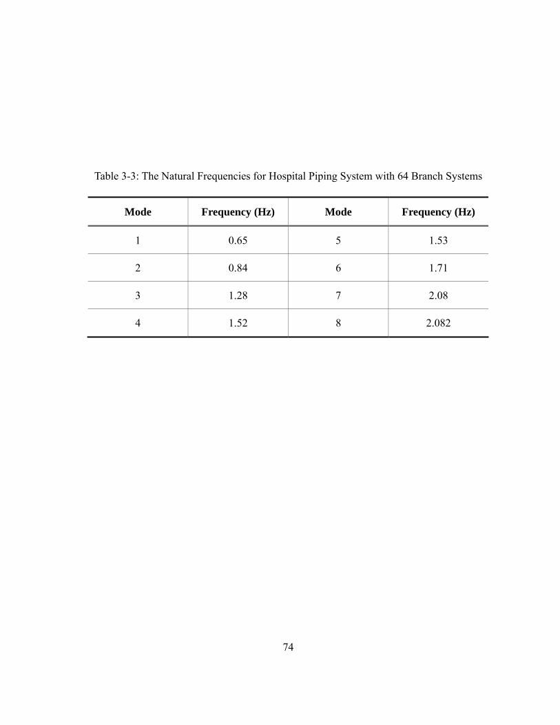
74
Table 3-3: The Natural Frequencies for Hospital Piping System with 64 Branch Systems
Mode Frequency (Hz) Mode Frequency (Hz)
1 0.65 5 1.53
2 0.84 6 1.71
3 1.28 7 2.08
4 1.52 8 2.082

75
Table 3-4: 75 Selected Seismic Events
No. Date Seismic Events, Location Component PGA (g)
1 2
May 18 1940
Imperial Valley El-Centro S00E S90W
0.89 0.55
3 4
July 21 1952
Kern County, Pasadena, Caltech-Athenaeum
S00E S90W
0.12 0.14
5 6
July 21 1952
Kern County, Taft, Lincoln School Tunnel
N21E S69E
0.40 0.46
7 8
July 21 1952
Kern County, Santa BarbaraCourt House
N42E S48E
0.23 0.33
9 10
July 21 1952
Kern County, Hollywood Storage, Basement
S00W N90E
0.14 0.11
11 12
March 22 1957
San Francisco Golden Gate Park
N10E S80E
0.21 0.27
13 14
March 10 1933
Long Beach Vernon CMD Building
S08W N82W
0.34 0.39
15 16
December 30 1934
Lower California, El-CentroImperial Valley
S00W S90W
0.41 0.47
17 18
October 31 1935
Helena, Montana Carrol Collage
S00W S90W
0.37 0.37
19 20
April 13 1949
Western Washington, SeattleDistr. Engs. Office
S02W N88W
0.17 0.17

76
Table 3-4: (Continued)
No. Date Seismic Events, Location Component PGA (g)
21 22
April 13 1949
Western Washington, Olympia, Hwy. Test Lab
S04W N86E
0.42 0.71
23 24
April 29 1965
Puget Sound, Olympia Hwy. Test Lab
S04W N86E
0.35 0.51
25 June 27
1966
Parkfield, California Cholame Shandon Array
No.2 N65E 1.25
26 27
June 27 1966
Parkfield, California Cholame Shandon Array
No.5
N05W N85E
0.90 1.11
28 29
June 27 1966
Parkfield, California Cholame Shandon Array
No.8
N50E N40W
0.60 0.70
30 31
June 27 1966
Parkfield, California Cholame Shandon Array
No.12
N50E N40W
0.14 0.16
32 33
June 27 1966
Parkfield, California Cholame Shandon Array
No.2
N65W S25W
0.69 0.89
34 35
February 9 1971
San Fernando Pacoima Dam
S16E S74W
2.98 2.74
36 37
February 9 1971
San Fernando 8244 Orion Blvd., 1st Floor
N00W S90W
0.65 0.34

77
Table 3-4: (Continued)
No. Date Seismic Events, Location Component PGA (g)
38 39
February 9 1971
San Fernando 250 E. First St.Basement
N36E N54W
0.26 0.32
40 41
February 9 1971
San Fernando, 445 Figueroa St. Basement
N52W S38W
0.38 0.30
42 43
February 9 1971
San Fernando Hollywood Storage Basement
S00W N90E
0.27 0.39
44 45
February 9 1971
San Fernando, Caltech Seismological Lab
S00W S90W
0.23 0.49
46 47
February 9 1971
San Fernando Caltech-Athenaeum
N00E N90W
0.24 0.28
48 49
February 9 1971
San Fernando Caltech Milliksan Lib., Basement
N00E N90E
0.52 0.47
50 51
February 9 1971
San Fernando Jet Propulsion Lab, Basement
S82E S08W
0.54 0.36
52 53
February 9 1971
San Fernando, Fire Station Storage Room
S60E S30W
0.29 0.35
54 55
February 9 1971
San Fernando, 15250 Ventura Blvd., Basement
N11W N79W
0.57 0.38

78
Table 3-4: (Continued)
No. Date Seismic Events, Location Component PGA (g)
56 57
June 28 1992
Landers Lucerne Valley Station
N15W N80W
1.88 1.64
58 59
January 17 1994
Northridge Pardee Station S00E N90E
1.26 0.75
60 61
January 17 1994
Northridge, Rinaldi Receiving Station
N42W S48W
1.22 2.12
62 63
January 17 1994
Northridge, Sylmar Converter Station
N52E S38E
1.52 1.91
64 65
January 17 1994
Northridge, Sylmar Converter Station East
N18E N72W
2.10 1.23
66 67
January 17 1994
Northridge, Newhall-LA County Fire Station
N90E N00E
1.51 1.50
68 69
January 17 1994
Northridge Arleta Fire Station
N90E N00E
0.87 0.75
70 71
January 17 1994
Northridge Tarzana-Cedar Hall Nuresery
N90E N00E
4.47 2.45
72 73
January 17 1994
Northridge Sylmar-County Hospital
N90E N00E
1.51 2.24
74 75
January 17 1994
Northridge, Santa Monica City Hall
N90E N00E
2.22 1.00

79
Figure 3-1: Threaded Tee-joint Test Setup for Experiment Conducted at UB

80
0 0.5 1 1.5 2 2.5 30
0.2
0.4
0.6
0.8
1
1.2
1.4
1.6
1.8
Displacement (in)
Forc
e (
kips
)
Figure 3-2: Force-Displacement, Monotonic Test Results and Failure Modes of Tee-joint,
Experiment Conducted at UB
0 0.02 0.04 0.06 0.08 0.1 0.120
5
10
15
20
25
Rotation (rad)
Mom
ent
(kip
-in)
Figure 3-3: Moment-Rotation (right), Monotonic Test Results and Failure Modes of Tee-joint,
Experiment Conducted at UB

81
0 0.02 0.04 0.06 0.08 0.1 0.12 0.14 0.16 0.18 0.20
5
10
15
20
25
Rotation (rad)
Mom
ent
(kip
-in)
Figure 3-4: Moment-Rotation (left), Monotonic Test Results and Failure Modes of Tee-joint,
Experiment Conducted at UB
Figure 3-5: Failure-Mode, Monotonic Test Results and Failure Modes of Tee-joint,
Experiment Conducted at UB

82
Figure 3-6: Loading Protocol for Cyclic Loading Tests
Figure 3-7: Force-Displacement, Cyclic Test Results of Tee-joint, Experiment Conducted at
UB
-3 -2 -1 0 1 2 3-2.5
-2
-1.5
-1
-0.5
0
0.5
1
1.5
2
2.5
Displacement (in)
For
ce (
kips
)
0 2 0 0 4 0 0 6 0 0 8 0 0 1 0 0 0-3
-2
-1
0
1
2
3
t im e (sec)
Am
pli
tud
e
(in
)

83
Figure 3-8: Moment-Rotation (right), Cyclic Test Results of Tee-joint, Experiment
Conducted at UB
Figure 3-9: Moment-Rotation (left), Cyclic Test Results of Tee-joint, Experiment Conducted
at UB
-0.2 -0.15 -0.1 -0.05 0 0.05 0.1 0.15-30
-20
-10
0
10
20
30
Rotation (rad)
Mo
men
t (k
ip-in
)
-0.15 -0.1 -0.05 0 0.05 0.1-30
-20
-10
0
10
20
30
Rotation (rad)
Mom
ent
(kip
-in)
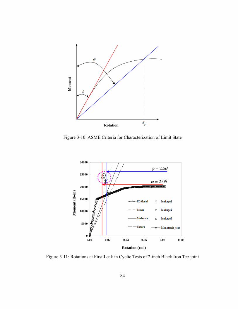
84
Figure 3-10: ASME Criteria for Characterization of Limit State
Figure 3-11: Rotations at First Leak in Cyclic Tests of 2-inch Black Iron Tee-joint
Mom
ent
Rotation
0
5000
10000
15000
20000
25000
30000
0.00 0.02 0.04 0.06 0.08 0.10
Rot (rad)
Mom
ent (
lb-i
n)M
omen
t (l
b-in
)
Rotation (rad)
2.5
2.0

85
Figure 3-12: FE Modeling of Tee-joint of 2-inch Black Iron Pipe

86
Figure 3-13: Loading Protocol for Monotonic Test
Figure 3-14: Validation of FE Model for Monotonic Test
0
5
10
15
20
25
0.0000 0.0200 0.0400 0.0600 0.0800 0.1000Rot (rad)
Mom
ent
(kip
s-in
)
Experimental_test
FE-modelMom
ent
(kip
-in)
Rotation (rad)
0 50 100 150 200 250 3000
0.5
1
1.5
2
2.5
3
time (sec)
am
plitu
de (
in)

87
Figure 3-15: Definition of OpenSees Pinching4 Uniaxial Material Model (Mazzoni et al,
2006)

88
Figure 3-16: Validation of FE Model for Cyclic Test

89
Figure 3-17: Hospital Piping System Layout

90
Figure 3-18: Main Piping System with a 2-inch Diameter Branch Containing the Threaded
Tee-joint
y
xz

91
0.00
0.20
0.40
0.60
0.80
1.00
0.00 0.50 1.00 1.50 2.00 2.50 3.00
PGA (g)
Pf
Minor Damage
ModerateDamage
SevereDamage
Figure 3-19: Seismic Fragility of Tee-joint Using Monotonic FE Model

92
Figure 3-20: Main Piping System with Two Branches Containing the Threaded Tee-joints
y
xz
Location 1
Location 2

93
0.0
0.2
0.4
0.6
0.8
1.0
0 0.5 1 1.5 2 2.5 3
PGA (g)
Pf
Location 1
Location 2
Figure 3-21: Seismic Fragility of Tee-joint Systems Using Monotonic FE Model

94
Figure 3-22: Main Piping System with Three Branches Containing the Threaded Tee-joints
Location 1
Location 2
Location 3
y
xz

95
0
0.2
0.4
0.6
0.8
1
0 1 2 3 4 5 6
PGA (g)
Pf
Location 1
Location 2
Location 3
Figure 3-23: Seismic Fragility of Tee-joint Systems Using Monotonic FE Model
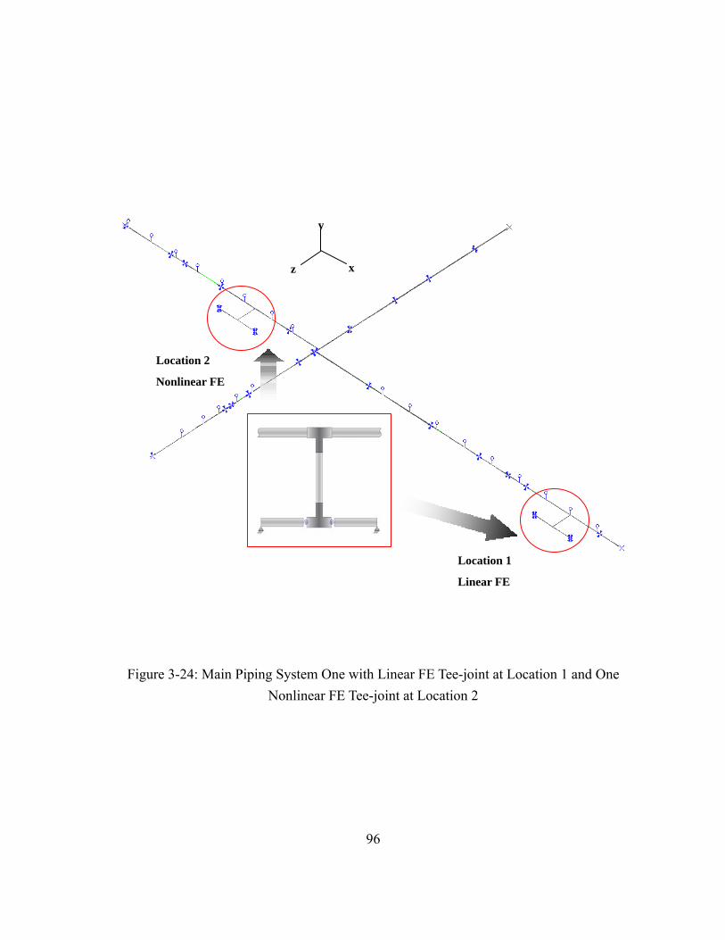
96
Figure 3-24: Main Piping System One with Linear FE Tee-joint at Location 1 and One
Nonlinear FE Tee-joint at Location 2
y
xz
Location 1
Linear FE
Location 2
Nonlinear FE

97
0
0.2
0.4
0.6
0.8
1
0 0.5 1 1.5 2 2.5 3 3.5 4
PGA (g)
Pf Nonlinear
Location 1
LinearLocation 1
Figure 3-25: Seismic Fragility of Tee-joint Systems Using Monotonic FE Model
Corresponding to First Leak at Location 2

98
Figure 3-26: The 2nd Mode Shape of Main Piping System at Location 1
y
xz
Location 1

99
Figure 3-27: The 3rd Mode Shape of Main Piping System at Location 2
Location 2

100
0.00
0.20
0.40
0.60
0.80
1.00
0.00 0.50 1.00 1.50 2.00 2.50 3.00
PGA (g)
Pf Minor
Damage
Moderate Damage
SevereDamage
Figure 3-28: Seismic Fragility of Tee-joint Systems Using Pinching 4 Model at Location 1
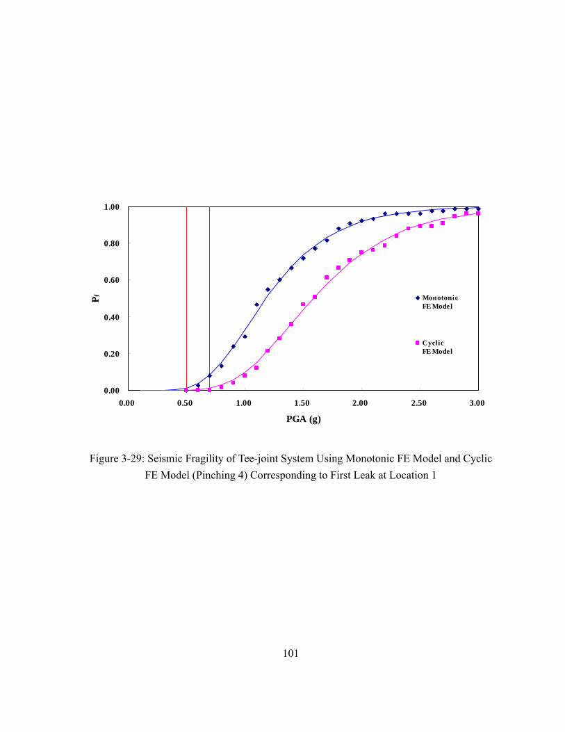
101
0.00
0.20
0.40
0.60
0.80
1.00
0.00 0.50 1.00 1.50 2.00 2.50 3.00
PGA (g)
Pf Monotonic
FE Model
Cyclic FE Model
Figure 3-29: Seismic Fragility of Tee-joint System Using Monotonic FE Model and Cyclic
FE Model (Pinching 4) Corresponding to First Leak at Location 1

102
0.00
0.20
0.40
0.60
0.80
1.00
0.0 0.5 1.0 1.5 2.0 2.5 3.0
PGA (g)
Pf
Location 1
Location 2
Figure 3-30: Seismic Fragility of Tee-joint Systems Using Pinching 4 Model Corresponding
to First Leak at Location 1 and 2

103
0.00
0.20
0.40
0.60
0.80
1.00
0.00 0.50 1.00 1.50 2.00 2.50 3.00
PGA (g)
Pf
Coupled
Decoupled
Figure 3-31: Seismic Fragility of Piping System Using Pinching 4 Model Corresponding to
First Leak at Location 1
104
PART IV
PIPING FRAGILITY EVALUATION: INTERACTION WITH
BUILDING PERFORMANCE
Bu Seog Ju and Abhinav Gupta

105
PIPING FRAGILITY EVALUATION: INTERACTION WITH BUILDING PERFORMANCE
Bu Seog Ju and Abhinav Gupta
ABSTRACT
Many recent studies have emphasized the need for improving seismic performance
of nonstructural systems in critical facilities in order to reduce the damage as well as to
maintain continued operation of the facility after an earthquake. This paper is focused on
evaluating system-level seismic fragility of the piping in a representative high rise and a low
rise building. Piping fragilities are evaluated by incorporating the nonlinear finite element
model of a threaded Tee-joint that is validated using experimental results. The emphasis in
this study is on evaluating the effects of building performance on the piping fragility. The
differences in piping fragility due to the nonlinearities in building are evaluated by
comparing the fragility curves for linear frame and nonlinear fiber models. It is observed that
as nonlinearity in the building increases with increasing value of peak ground acceleration,
the floor accelerations exhibit a reduction due to degradation/softening. Consequently, the
probabilities of failure increase at a slower rate relative to that in a linear fiber. It is also
observed that a piping located at higher floor does not necessarily exhibits high fragilities, i.e.
the fundamental building mode is not always the governing mode. Higher order building
modes with frequencies closest to critical piping modes of interest contribute more
significantly to the piping fragility. Within a particular building mode of interest, a good
106
indicator of the amplification at different floor levels can be obtained by the product of mode
shape ordinate and modal participation factor. Piping fragilities are likely to be higher at
floor levels at which this product has a higher value.
1. INTRODUCTION
Observations from earthquake related failures have emphasized the significance of
improving the seismic performance of not only the primary structures such as buildings and
bridges but also of the nonstructural secondary systems such as equipment and piping. In
many cases, these secondary nonstructural systems do not pose a direct threat to life safety
but these systems must remain functional to provide protection against secondary threats
such as fires especially in critical facilities like hospital buildings, nuclear power plants,
petrochemical and other industrial facilities. Over the past 2 decades or so, failure of
nonstructural components has resulted in significant economic loss and closure of critical
facilities even though the primary structural components and buildings did not exhibit any
damage. For example, during the 1994 Northridge earthquake, the Olive View Medical
Center had suffered no structural damage but the hospital was shut down due to the water
leakage from fire protection sprinkler piping system and chilled water piping system
(Reitherman et al. 1995). In terms of the economic impact, the construction costs associated
with the nonstructural systems/components can be as high as $103 million out of the $170
million total construction cost of a hospital, approximately 60% of the total construction cost
(Horne and Burton, 2003).

107
In recent years, some studies have been conducted to evaluate and improve the
seismic performance of nonstructural components such as piping systems, mechanical
equipment, and HVAC systems. Shinozuka and Masri (2003) conducted seismic risk
assessments of water systems for fire suppression and electrical power systems in hospital
buildings. The focus of this analysis was to estimate the annual probability of failure
subjected to the earthquake ground motions and to provide optimal strengthening or
retrofitting by integrating nonstructural component fragility enhancement and seismic
response of structural system. Miranda and Taghavi (2003) evaluated seismic demands on
acceleration sensitive rigid and flexible secondary systems in critical facilities. In particular,
this study investigated that frequency content of earthquake ground motions and dynamic
characteristics of the primary structural systems such as the fundamental period which can
influence the acceleration demands along the building height significantly.
The dynamic characteristics of building structural systems and nonstructural
components/contents such as piping systems can be quite different. Most of the building
response can be contained in the fundamental mode whereas the response of piping systems
is highly dependent upon higher order modes because piping modes are typically local modes,
i.e. a fundamental mode which is local to a certain part of the piping system may have no
influence on the performance/response at a location far from this localized zone.
The objective of this research is to develop the system-level fragility of piping
systems in critical facilities by considering the effect of nonlinearities in the buildings on
which the piping systems are supported. The purpose is to evaluate the effects of filtering the
earthquake motion through a typical high rise building and through a typical low-rise

108
building on the piping fragility curve. Piping fragilities are evaluated for buildings that
remain linear as wells as for buildings that exhibits significant nonlinear behavior. A related
objective is to evaluate the changes in fragility curve for piping located at different elevations
of the buildings. The piping system considered for the purpose of this study is same as that
described in detail in Part-III of this dissertation.
2. DESCRIPTION OF BUILDINGS CONSIDERED
For the purpose of this study, we consider a 20 story building that is representative of
a typical high rise building and a 5 story building that is representative of the low rise
building. Figure 4-1 shows the single bay idealized 5 and 20 story reinforced concrete
moment resisting frame building configurations. These buildings are based on the building
design details provided in Wood et al. (2009). Both buildings are assumed to have same foot
print of 150 ft by 120 ft. A total of 5 bays exist in each direction such that the width of
longitudinal bay is 360 in, that of transverse bay is 288 in, and that of story height is 144 in.
Both the buildings are assumed to be fixed at their base. The analysis is conducted only for
the longitudinal direction of the prototype building. For the simplicity in analysis, only a
single bay is analyzed. A live load of 0.348 psi is assumed, which is in accordance with ICC
(2006). In addition to the self-weight of the members and a 0.95 in thick two-way floor slab,
a superimposed dead load of 0.1389 psi is also considered. The reinforced concrete
considered for the design of this building is conventional concrete with a 28-day unconfined
compressive strength of 5 ksi for the beams and a range of 5 – 10 ksi for the columns. The

109
concrete weight is assumed to be 1.0 psi. Reinforcing steel is taken as Grade 60 with a design
yield tensile strength of 60 ksi.
According to Wood et al. (2006), the design of the buildings is governed by IBC
(ICC, 2006) and ACI 318-08 (ACI, 2008). The IBC 2006 design code is used to evaluate
estimates of the base shear, period, and lateral force distribution. The general concrete
design and detailing is done as per ACI 318-08 with particular emphasis on Chapter 21. The
strong column-weak beam philosophy is adopted for the frame design, i.e. the sum of the
moment capacity at the columns is designed to be at least 20% greater than the sum of the
moment capacity at the beams. Both the building designs are governed by seismic loading.
For simplicity in the detailing of the beams and columns, the reinforcing steel is taken to be
in one layer. The shear reinforcement is provided using the double leg #5 stirrups. The
confinement spacing resulted in shear reinforcement providing a minimum lateral pressure of
9% of the target f’c (Englekirk, 2003) within the assumed plastic hinge zone. The
compression reinforcement is considered to be equal to the tension reinforcement. A single
longitudinal reinforcement layer is considered on each side for column detailing. Table 4-1
provides the design details of the various beams and columns in the buildings. The range of
longitudinal reinforcing steel ratios for the columns and beams is 1.1 – 2.7%. Additional
building design details can found in Wood et al. (2009).
2.1 NUMERICAL MODELING OF NONLINEAR FIBER MODEL
Numerical simulation of the nonlinear fiber models is performed using the OpenSees

110
(2010) platform. As described in Wood et al. (2009), two dimensional lumped mass
idealizations are developed and considered for the prototype buildings. The damping ratio for
all the modes is taken as 5%. Several material models such as concrete and steel are available
in OpenSees platform and various types of element models for linear and nonlinear analyses
can be also used. In this study, to develop the fiber section, concrete02 material (Figure 4-2)
is adopted as a uniaxial model with tensile strength and linear tension softening. For steel
section, steel02 model (Figure 4-3) named as Giuffre-Menegotto-Pinto steel material with
isotropic strain hardening is used (Mazzoni et al. 2006). The building models are discretized
using the BeamWithHinges element (Scott and Fenves, 2006). This element is selected as it
can be integrated with nonlinear fiber sectional discretization and has demonstrated good
performance for members anticipated to undergo nonlinearity as well as softening or
degradation (Scott and Fenves, 2006). The BeamWithHinges element also eliminates the
nonobjective curvature response due to its sensitivity to the number of integration points
(Coleman and Spacone, 2001). The element is developed as a force-based, lumped plasticity,
zero-volume line element with two different sections, namely, a fiber section at each end,
which represents the plastic hinge over a discrete length Lp and an interior linear elastic
section (Melo et al. 2011) as shown in Figure 4-4. In the development of the fiber section in
the end regions, the linear tension strength concrete (concrete02 model) and the Menegotto-
Pinto model (steel02 model) are used. The effects of confinement are considered using the
model of Mander et al. (1988). The plastic hinge lengths (Lp) of the beam and column
elements are specified using the Paulay and Priestley (1992) analytical model.

111
2.2 NUMERICAL MODELING OF LINEAR FRAME MODEL
For comparing the effect of building nonlinearity on piping fragility with the
fragility curves evaluated in the corresponding building that remains linear, we also consider
a modified design of the building described above. To do so, the numerical model
discretization for the fiber sections of linear frame models is designed with an elastic uniaxial
material based on nonlinear fiber sections. The elasticBeamColumn element in OpenSees is
used to characterize the linear response of the frame sections for beams and columns under
earthquake ground excitations. The damping in the linear frame model, however, is
considered to be same as that in the nonlinear fiber model, i.e. 5% modal damping ratio in all
the modes.
3. PIPING SYSTEM LAYOUT
The piping system, shown in Figure 4-5, is same as that considered and described
earlier in the Part III of this dissertation. The piping system, originally designed as per
NFPA-13(2007) and SMACNA (2003), is selected from a hospital building in California.
This piping system was made up of 2, 3, and 4 inch diameter schedule 40 black iron pipe and
the system is braced by transverse/longitudinal hangers and anchors at the ends of the pipes.
Additional piping system design detail can found in the manuscript given in Part- III of this
dissertation.

112
4. MODAL CHARACTERISTICS OF UNCOUPLED BUILDING AND
PIPING SYSTEMS
Table 4-2 gives the natural frequencies and mass participation in the first 5 modes of
the 20 story nonlinear and linear frame models whereas Table 4-3 gives the corresponding
values for the 5 story nonlinear and linear frame models. It can be seen that the first 4 modes
of each building model account for more than 90% of the total mass participation. The
fundamental natural frequencies for the 20-story and the 5-story linear frame models are
0.53Hz are 2.62Hz, respectively. The frequencies for the 20 and 5 story nonlinear fiber
models are relatively less, i.e. 0.48Hz and 2.42Hz, respectively. Table 4-4 gives the natural
frequencies for the first 6 modes of the piping systems. It can be seen that the frequencies of
the first and the second modes in the piping system are 1.82Hz to 3.142Hz, respectively.
Therefore, the fundamental piping system mode is close to, and therefore interacts most with,
the second mode of the 20 story building models. Similarly, the second piping system mode
interacts most with either the third or the fourth modes of the 20 story building models. Since
the 5 story building models are much stiffer than the 20 story building models, the
fundamental mode of the 5 story building model interacts with both the fundamental and the
second mode of the piping system.
Figure 4-6 to 4-7 shows the first four mode shapes of 5-story and Figure 4-8 to 4-9
that of the 20-story linear and nonlinear fiber models, respectively. The mode shapes for the
first 2 modes of the piping system are shown in Figure 4-10. As can be seen in this figure, the
fundamental piping mode is a local mode that is located far away from the location of the 2-

113
inch diameter branch piping with the threaded Tee-joint which is the location of interest for
evaluating piping fragility. However, the second piping mode shape shown in Figure 8 occurs
in the region of the 2-inch diameter branch piping. Therefore, the second piping mode and its
interaction with the corresponding building modes are expected to contribute significantly to
the piping fragility.
5. FINITE ELEMENT MODEL OF THE THREADED TEE-JOINT
As discussed in detail in the manuscript presented in Part-III of this thesis, the
system-level fragility for this piping is determined by incorporating experimentally validated
finite element model of the nonlinear behavior at the threaded Tee-joint within the complete
piping system model. As explained in Part-III, the 2 inch diameter black iron pipe threaded
Tee-joint is modeled in OpenSees platform by using two nonlinear rotational springs. The
moment-rotation curves for the nonlinear springs are obtained based on the component level
experiments conducted on several of this threaded Tee-joint at University at Buffalo (Dow,
2010). The equivalent rotational spring model used to model this behavior is shown in Figure
4-11. The Pinching4 uniaxial material model available in OpenSees is used to model the
moment-rotation behavior for the Tee-joint. This model is capable of considering
unloading/reloading, stiffness degradation, and strength degradation under cyclic loading.
Figure 4-12 compares the simulation using the Pinching4 model with the experimentally
evaluated moment-rotation curve. As can be seen from this figure, the Pinching4 model is
adequate to represent the experimentally evaluated behavior.

114
6. SEISMIC FRAGILITY EVALUATION
Seismic fragility of structural and nonstructural systems is the conditional
probability of its failure for a given level of engineering design parameter such as Peak
Ground Acceleration (PGA) (Sundararajan, 1995). Seismic fragility can be described by
means of a family of fragility curves reflecting the uncertainty in the parameter values and in
the models. The fragility curves are developed on the premise that the component could fail
in any of the potential failure modes (Sundararajan, 1995).
The first step in the evaluation of seismic fragility curves is to characterize the limit
state for the purpose of defining failure associated with critical components. In this study, the
limit state for the “first-leakage” of the 2 inch black iron piping system is characterized based
on the alternative form of the ASME’s “Twice the Elastic Slope” criteria (ASME Section III
BVP & P Code, Gerdeen, 1979) as described in detail in the Part-III of this dissertation.
Based on this criterion, the limiting rotation characterizing the “first-leakage” would
correspond to 0.0135 radians, i.e. lim = 0.0135. The fragility values for a given value of the
engineering demand parameter can be calculated as per Equation (1) given below.
PGAPPf |lim (3)
In a simulation based approach, multiple earthquake records normalized to the same
value of engineering demand parameter are used to conduct the nonlinear time history
analysis of the complete system. The Conditional probability of failure Pf is modeled as a
function of inelastic rotation as
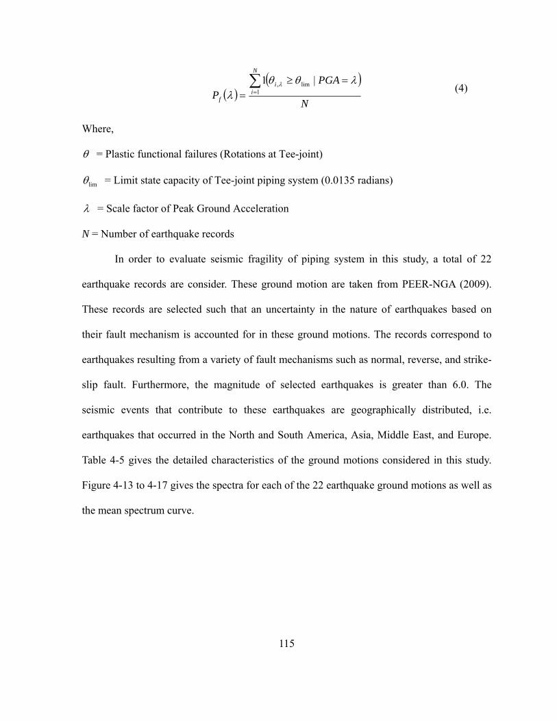
115
N
PGAP
N
ii
f
1
lim, |1
(4)
Where,
= Plastic functional failures (Rotations at Tee-joint)
lim = Limit state capacity of Tee-joint piping system (0.0135 radians)
= Scale factor of Peak Ground Acceleration
N = Number of earthquake records
In order to evaluate seismic fragility of piping system in this study, a total of 22
earthquake records are consider. These ground motion are taken from PEER-NGA (2009).
These records are selected such that an uncertainty in the nature of earthquakes based on
their fault mechanism is accounted for in these ground motions. The records correspond to
earthquakes resulting from a variety of fault mechanisms such as normal, reverse, and strike-
slip fault. Furthermore, the magnitude of selected earthquakes is greater than 6.0. The
seismic events that contribute to these earthquakes are geographically distributed, i.e.
earthquakes that occurred in the North and South America, Asia, Middle East, and Europe.
Table 4-5 gives the detailed characteristics of the ground motions considered in this study.
Figure 4-13 to 4-17 gives the spectra for each of the 22 earthquake ground motions as well as
the mean spectrum curve.

116
7. PIPING FRAGILITY EVALUATION: INTERACTION WITH
BUILDING PERFORMANCE
7.1 GENERATION OF FLOOR ACCELERATION TIME HISTORIES
In order to consider the effect of building performance on the piping fragility, we
conducted time history analyses of each building model for all individual 22 ground motion
records and evaluated acceleration time histories at various floors. To do so, the ground
motions are first normalized to a given value of PGA. Therefore, 22 time history analyses of
the building models are needed for each normalized value of PGA considered for generating
the fragility curve, i.e. for each value of in Equation (2).
In 20-story building model, the floor accelerations time histories are obtained from
the ground motion records normalized to the same PGA levels at 5th, 10th, 15th, and 20th
floors, respectively. For the 5-story building system, the floor acceleration time histories are
evaluated at each of the 5 floors. A noticeable uncertainty in the process of generating floor
motions is related to the fact that the range of PGA in which the piping fragility curve goes
from zero to unity is not known a-priori. For example, let us consider that the ground time
histories are normalized to a PGA value of 0.3g and the corresponding floor time histories
are evaluated by nonlinear analyses of the building model. The floor time histories are then
used to conduct nonlinear analyses of the piping system. Once all these analyses are
completed, one may find that none of the time histories resulted in a piping failure even if
significant nonlinearity existed in the building system model. Consequently, all these

117
analyses would not result in generating even a single point on the fragility curve. Therefore,
the complete process of generating the piping fragility curve by considering building
performance can be computationally quite intensive. In this study, we used a preliminary
iterative procedure to determine that a variation of PGA from 0.2g to 3.0g is sufficient to
evaluate the complete fragility curve for the piping system in the various building models. In
order to better understand the effect of building performance on the piping system fragility,
we evaluated floor spectra for each case. For brevity, we have included the mean spectra at
various floor levels for only a single case of normalization equal to 1.0g, i.e. the case for
which each ground motion record is normalized to a PGA of 1.0g. Figure 4-18 gives the
mean spectra at various floor levels of the nonlinear 20 story building model including the
mean spectra at the ground level. Similarly, Figure 4-19 gives the spectra for the linear 20
story building, Figure 4-20 for the nonlinear 5 story building, and Figure 4-21 for the linear 5
story building, respectively. Each of these figures contains two vertical lines. These lines
correspond to the frequencies of the first two piping system modes.
Before proceeding further with the evaluation of piping fragility, we examine the
degree of nonlinearity in the building models. This is particularly important because we
consider both the linear and the nonlinear fiber models to emphasize the effect of building
nonlinearity. Figures 4-22 to 4-30 give selected moment-rotation curves for at three different
floor levels, 1st, 10th, and 20th floors, in the 20 story nonlinear fiber model. Figure 4-31 gives
the story drift ratios for all the earthquake records. As seen in this figure, the building model
exceeds the limiting story drift of 0.02 (UBC, 1997) for only 4 of the 22 earthquakes
considered.

118
7.2 PIPING FRAGILITY FOR 20-STORY BUILDING MODELS
The piping fragility for “first-leakage” at the threaded Tee-joint location in the 2 inch
black iron pipe is shown in Figure 4-32 for the nonlinear fiber model. As seen in this figure,
fragility curves are presented at different floor levels and also compared to the fragility curve
evaluated by directly using the ground motions which is representative of the piping fragility
curve evaluated without considering the effect of building performance, i.e. at the ground
level. As seen in this figure, the piping fragility is significantly higher due to dynamic
interaction with the building. However, it must be noted that the piping fragility does not
increase with increasing floor level. Even though the relative value of piping fragility are
quite high for a system located on the 20th floor, the piping fragilities for a system located on
15th floor are about the smallest among the four floor levels considered in this study.
Observations similar to those noted above can be made for the fragility curves in the
case of the 20-story linear frame model. Figure 4-33 gives the piping fragility curves at
different floor levels for the 20-story linear frame model case and also compare them to those
for the ground level case. Once again, the piping fragilities do not necessarily increase with
an increase in the floor elevation.
At first, the observation that the fragility at 15th floor is about the least among all the
floor levels considered appears intriguing. However, it can be explained as follows. While
much of the building performance is governed by the fundamental building mode, the piping
performance is governed by the tuning of the building and the piping modes. As observed by
the values of frequencies for the building models and the piping models, the fundamental

119
mode of the piping system is nearly tuned to the second mode of both the nonlinear and the
linear 20-story building models. Consequently, the relative contribution of the second
building mode is much greater than that of the fundamental building mode even though the
mass participation of the fundamental building mode is much greater. Once the significance
of the second building mode is established, the differences in the fragilities at various floor
levels can be explained by examining the product of the mode shape ordinate ( ) and the
modal participation factor ( ) at each floor in the second mode. In the case of nonlinear fiber
model, the product of gamma ( ) phi ( ) is equal to 0.6470 at 20th floor, 0.0159 at 15th floor,
0.4654 at the 10th floor, and 0.3685 at the 5th floor, respectively. It is quite evident that the
amplification at 15th floor is about the smallest among the four floor levels and, therefore, the
piping fragilities at the 15th floor are relatively less. Similarly, the products of gamma( ) and
phi( ) in the case of linear 20 story building are -0.6298, -0.0030, 0.4673, and 0.3830 at the
20th, 15th, 10th, and 5th floor levels, respectively, indicating a similar trend. It must be noted
that this observation is quite specific to the 20 story building model considered in this study
and should not be considered as a generic behavior.
Next, the piping fragility curves for the cases of linear frame and nonlinear fiber
models are compared in Figures 4-34 to 4-37 for various floor levels. As seen in these figures,
the piping fragilities are relatively higher in the case of linear frame models at the 20th floor
and the 5th floor. In general, the piping fragility in a linear frame model can be relatively
higher because the frequencies of the nonlinear fiber model modes are smaller than the
corresponding values for the linear frame model modes due to the softening/degradation of

120
beams and columns. Consequently, the linear frame model modes have greater degree of
tuning with the piping system modes thereby leading to higher piping fragilities. It must be
noted that it is quite possible in some cases for a nonlinearity in the building to increase the
degree of tuning with the piping system modes of interest which in turn would lead to higher
fragilities for piping system. In contrast to the observations made for the 20th and the 5th
floors, the piping fragilities at the 10th and the 15th floors in a linear frame model are
relatively lower in certain regions especially at lower PGA values. The primary reason for
such an observation is related to the degree of degradation at lower PGA values. As the PGA
values increase, the degree of degradation in both the building and the piping increases.
Therefore, the degree of tuning between the two individual systems changes continually at
different PGA levels and influences the evolution of the fragility curve.
7.3 PIPING FRAGILITY FOR 5-STORY BUILDING MODELS
Figures 4-38 and 4-39 give the piping fragility curves in 5-story linear frame and
nonlinear fiber models, respectively. The fragility curves for the piping system are developed
at each floor in the 5-story linear frame and nonlinear fiber model. As seen in this figure, the
piping fragility increases with increasing floor level. This is so because the 5-story linear
frame and nonlinear fiber models are relatively stiffer with a natural frequency of the
fundamental mode equal to 2.63Hz and 2.42Hz, respectively. Therefore, both the first and the
second mode of the piping system interact with the fundamental building mode in each case.
The amplification in the fundamental building mode increases with an increase in the floor

121
elevation. This can be seen in the values of the product of the mode shape ordinate ( ) and
the modal participation factor ( ) at each floor level in the fundamental mode. The values of
this product are equal to 0.1722, 0.5005, 0.8372, 1.1140, and 1.3074 at the 1st, 2nd, 3rd, 4th,
and 5th floor of the linear frame model, respectively. The corresponding values for the
nonlinear fiber model are 0.1721, 0.4982, 0.8345, 1.1129, and 1.3093, respectively.
8. CONCLUSIONS
This paper presents the results of a detailed study on the evaluation of piping
system fragility curves by incorporating the nonlinear moment-rotation characteristics of a 2-
inch threaded Tee-joint of a black iron pipe in the system level piping model. The particular
focus is on the evaluating the effect of interaction between the building and the piping on the
piping fragility. The effect of building behavior is included by considering low rise 5-story
and high rise 20-story building models. For each of the two building models, piping
fragilities are evaluated by considering the building to exhibit significant nonlinearity in the
beams and columns as well as by considering the buildings to remain linear for each of the
22 real ground motion records. In order to consider the effect of nonlinearity in building
model, the ground motion records are taken from relatively larger magnitude earthquakes
(greater than 6) that are recorded in different parts of the world. It is observed that the
fundamental building mode is not necessarily critical contributing mode in the evaluation of
piping fragilities. Same is true for the fundamental piping system mode. Since piping system
modes are local in nature, the piping mode that causes excitation around the location of the

122
critical component such as the threaded Tee-joints governs the piping performance.
Furthermore, the building mode with frequency closest to the governing piping system mode
influences the piping system fragility more critically. It is also observed that the piping
system fragilities can be higher in a linear frame model whose modes have greater degree of
tuning with the piping system modes. However, in some cases the piping system fragility can
be higher for the nonlinear fiber models if the nonlinearity increases the degree of tuning
between the piping and the building modes. The piping fragility does not necessarily
increases with the increasing floor levels in a high rise building. The product of modal
participation factor and the mode shape ordinate in the most critical building mode gives a
good estimate of the relative amplification at different floor levels and consequently the
relative increase or decrease in the piping fragility. Finally, it must be noted that as the degree
of degradation in a nonlinear fiber model increases with increasing values of the peak ground
accelerations, the effect of tuning between the building and the piping modes can either
increase or decrease. Such a variation in the degree of tuning leads to a corresponding change
in the piping fragility.

123
ACKNOWLEDGEMENTS
This research was partially supported by the National Science Foundation (NSF) and the
Center for Nuclear Power Plant Structures, Equipment and Piping at North Carolina State
University. Resources for the Center come from industry, National Science Foundation, the
Civil Engineering Department, and College of Engineering in the University.

124
REFERENCES
Antaki, G. (2004). “Seismic Capacity of Threaded, Brazed and Grooved Clamped Joints,” ASME 2004, PVP-Vol. 486-1, Seismic Engineering, 135-145 Antaki, G. and Guzy, D. (1998). “Seismic Testing of Grooved and Threaded Fire Protection
Joints and Correlation with NFPA Seismic Design Provisions,” ASME 1998, PVP-Vol. 364,
Seismic Engineering-1998, 69-75
Ayres, J. M. and Phillips, R. J. (1998). “Water Damage in Hospital Resulting from the
Northridge Earthquake,” ASHRAE Transactions Part 1B, SF-98-14-2, 1286-1296
Bachman, R. (2003).”Engineering Demand Parameters (EDPs) for Nonstructural
Components,” PEER Annual Meeting
Bachman, R. and et al. (2004). “Engineering Demand Parameters for Nonstructural
Components,” ATC-58 Project Task Report, ATC, Redwood City, California
Coleman, J., and Spacone, E. (2001) “Localization Issues in Force-Based Frame Elements.”
Journal of Structural Engineering, ASCE. Vol. 127, No.11, 1257-1265.
Dow, J. (2010). “Testing and Analysis of Iron and Plastic Tee-joint in Sprinkler Systems,”
NEESR-GC: “Simulation of the Seismic Performance of Nonstructural Systems”
http://nees.org/site/oldnees/filedir_2/REU2009_Dow_Paper.pdf
Fleming, R. P. (1998). “Analysis of Fire Sprinkler Systems Performance in the Northridge
Earthquake,” National Institute of Standards and Technology, NIST-GCR-98-736
Fleming, R. P. (2007). “The Evolution of Seismic Design of Fire Sprinkler Systems,”
National Fire Sprinkler Association, Patterson, NY, 2007
Gerdeen, J. C. (1979). “A Critical Evaluation of Plastic Behavior Data and A United
Definition of Plastic Loads for Pressure Components,” Welding Research Council (WRC)

125
Bulletin 254
Horne, J. and Burton, H. (2003). “Investigation of Code Seismic Force Levels for Hospital
Equipment,” Proceedings of Seminar on Seismic Design, Performance, and Retrofit of
Nonstructural Components in Critical Facilities, ATC-29-2, Newport Beach, California
Kircher, C. A. (2003). “It Makes Dollars and Sense to Improve Nonstructural System
Performance,” Proceedings of Seminar on Seismic Design, Performance, and Retrofit of
Nonstructural Components in Critical Facilities, ATC-29-2, Newport Beach, California
Mazzoni, S. and et al. (2006). “OpenSees Command Language Manual,” Open System for
Earthquake Engineering Simulation (OpenSees), http://opensees. berkeley.edu/
Melo, J and et al. (2011). “Numerical Modeling of the Cyclic Behavior of RC Elements Built
with Plain Reinforcing Bars,” Engineering Structures, 33(2011), 273-286
Miranda, E. and Taghavi, S. (2003). “Estimation of Seismic Demands on Acceleration-
Sensitive Nonstructural Components in Critical Facilities,” Proceedings of Seminar on
Seismic Design, Performance, and Retrofit of Nonstructural Components in Critical
Facilities, ATC-29-2, Newport Beach, California
NFPA-13 (2007). “Standard for the installation of Sprinkler System,” National Fire
Protection Association, MA, 2007 Edition
Paulay, T. and Priestley, M. J. N. (1992). Seismic Design of Reinforced Concrete and
Masonry Buildings, John Wiley, and Sons Inc.
PEER-NRG NGA (2009). (Pacific Earthquake Engineering Research Center: NGA Database),
http://peer.berkeley.edu/nga/
Reitherman, R. and Sabol, T.A. (1995). ”Northridge earthquake of January 17, 1994:
reconnaissance report-nonstructural damage.” Earthquake Spectra, EERI,11, 453-514
Shinozuka, M. and Masri, S. (2003). “Seismic Risk Assessment of Non-Structural

126
Components in Hospitals,” Proceedings of Seminar on Seismic Design, Performance, and
Retrofit of Nonstructural Components in Critical Facilities, ATC-29-2, Newport Beach,
California
SMACNA (2003). “Seismic Restraint Manual Guidelines for Mechanical Systems,” Sheet
Metal and Air Conditioning Contractors’ National Association, Inc., 2003
Sundararajan, C. (1995). Probabilistic Structural Mechanics Handbook, Theory and
Industrial Applications, Chapman and Hall, a Division of International Thomson Publishing
Inc.
UBC (1997). “Uniform Building Code,” International Conference of Building Officials, Vol.
2.
Wood, R.L., Hutchinson, T.C., and Hoehler, M.S. (2009). “Cyclic Load and Crack Protocols
for Anchored Nonstructural Components and Systems,” Structural Systems Research Project
Report Series, SSRP 09/1, Department of Structural Engineering, University of California,
San Diego,La Jolla, California.

127
Table 4-1: Description of Building Design (Woods et al. 2009)
Beam Column Floor
Level b (in) h (in) Strength
fc’(ksi)
Long.
Reinf. b (in) h (in)
Strength
fc’(ksi)
Long.
Reinf.
Level 01
to
Level 10
32.00 32.00 5.00 13 - #9 36.00 36.00 10.00 24 -
#10
Level 11
to
Level 15
30.00 30.00 5.00 12 - #9 34.00 34.00 10.00 20 -
#10
Level 16
to
Level 20
24.00 28.00 5.00 9 - #9 32.00 32.00 10.00 16 -
#10

128
Table 4-2: Frequencies and Mass Participation in 20-Story Building Models
Linear Frame Model Nonlinear Fiber Model
Frequency (Hz)
Mass
Participation
(%)
Frequency (Hz)
Mass
Participation
(%)
Mode 1 0.53 73.25 0.48 78.06
Mode 2 1.56 13.85 1.41 13.68
Mode 3 2.85 4.13 2.54 4.26
Mode 4 4.24 2.48 3.82 2.57
Mode 5 5.86 1.37 5.29 1.39

129
Table 4-3: Frequencies and Mass Participation in 5-Story Building Models
Linear Frame Model Nonlinear Fiber Model
Frequency (Hz)
Mass
Participation
(%)
Frequency (Hz)
Mass
Participation
(%)
Mode 1 2.63 78.62 2.41 78.54
Mode 2 9.17 12.42 8.45 12.57
Mode 3 19.15 5.34 17.61 5.39
Mode 4 32.33 2.69 29.38 2.64
Mode 5 44.86 0.93 40.17 0.86

130
Table 4-4: Frequencies of Piping System
Piping System
Mode Frequency (Hz) Mode Frequency (Hz)
Mode 1 1.82 Mode 4 3.33
Mode 2 3.14 Mode 5 4.05
Mode 3 3.30 Mode 6 6.34

131
Table 4-5: Characteristics of Ground Motion Records Used
No. Date Seismic
Events Locations
Magnitude
(Mw) PGA (g)
1 January 17
1994 Northridge
Beverly Hills,
USA 6.7 0.5165
2 January 17
1994 Northridge
Canyon Country,
USA 6.7 0.482
3 November 12
1999 Duzce
Bolu,
Turkey 7.1 0.8224
4 October 16
1999 Hector Mine Hector 7.1 0.3368
5 October 15
1979
Imperial
Valley Delta 6.5 0.3511
6 October 15
1979
Imperial
Valley
El Centro
Array #11 6.5 0.3796
7 January 16
1995 Kobe
Nishi-Akashi
Japan 6.9 0.5093
8 January 16
1995 Kobe
Shin-Osaka
Japan 6.9 0.2432
9 August 17
1999 Kocaeli Duzce 7.5 0.3579
10 August 17
1999 Kocaeli Arcelik 7.5 0.2188
11 June 28
1992 Landers
Yermo Fire
Station 7.3 0.2448

132
Table 4-5: (Continued)
No. Date Seismic
Events Locations
Magnitude
(Mw) PGA (g)
12 July 23
1992 Landers Coolwater 7.3 0.4169
13 October 18
1989 Loma Prieta Capitola 6.9 0.5285
14 October 18
1989 Loma Prieta Gilroy Array 6.9 0.5550
15 July 20
1990 Manjil Manjil, Iran 7.4 0.5146
16 November 24
1987
Superstition
Hills
El Centro IMP
Co Center 6.5 0.3579
17 November 24
1987
Superstition
Hills POE Road 6.5 0.4463
18 April 25
1992
Cape
Mendocino
Rio Dell
Overpass FF 7.0 0.5489
19 September 20
1999 Chi-Chi
CHY 101,
Taiwan 7.6 0.4401
20 September 20
1999 Chi-Chi
TCU045,
Taiwan 7.5 0.5120
21 February 09
1971 San Fernando
LA Hollywood
Stor Lot 6.6 0.2099
22 January 17
1994 Northridge
Beverly Hills
14145 Mulh 6.7 0.5165

133
20-Story Building Model 5-Story Building Model
Figure 4-1: RC Moment Frame Building Configurations

134
Figure 4-2: Nonlinear Concrete Model (Concrete02) in OpenSees (Mazzoni et al, 2006)
Eo=2*fc’/ εc,max
(εc,max, fc’)
(εcu, fcu)
λ*Eoft
Ets
Eo=2*fc’/ εc,max
(εc,max, fc’)
(εcu, fcu)
λ*Eoft
Ets
Eo=2*fc’/ εc,max
(εc,max, fc’)
(εcu, fcu)
λ*Eoft
Ets

135
Figure 4-3: Nonlinear Steel Model (Steel02) in OpenSees (Mazzoni et al, 2006)
Figure 4-4: Plastic Hinge Element in OpenSees (Mazzoni et al, 2006)
LLpi Lpj
Linear ElasticLinear Elastic
node i node j
Plastic Hinges
LLpi Lpj
Linear ElasticLinear Elastic
node i node j
LLpi Lpj
Linear ElasticLinear Elastic
LLpi LpjLLpi LpjLLpi Lpj
Linear ElasticLinear Elastic
node i node j
Plastic HingesPlastic Hinges

136
Figure 4-5: Piping System Layout
y
xz

137
Figure 4-6: Mode Shapes of 5-Story Linear Building Model
0
0.2243
0.6517
1.0902
1.4507
1.7025
0
1
2
3
4
5
-1.0 -0.5 0.0 0.5 1.0 1.5 2.0
Mode 1
0
-0.7366
-1.5271
-1.2626
0.0088
1.4826
0
1
2
3
4
5
-2.0 -1.5 -1.0 -0.5 0.0 0.5 1.0 1.5 2.0
Mode 2
0
-1.3126
-1.1694
0.9518
1.2493
-1.0534
0
1
2
3
4
5
-2.0 -1.5 -1.0 -0.5 0.0 0.5 1.0 1.5 2.0
Mode 3
0
1.6417
-0.5306
-1.0361
1.4932
-0.6220
0
1
2
3
4
5
-2.0 -1.5 -1.0 -0.5 0.0 0.5 1.0 1.5 2.0
Mode 4

138
Figure 4-7: Mode Shapes of 5-Story Nonlinear Building Model
0
0.2243
0.6491
1.0873
1.4500
1.7059
0
1
2
3
4
5
-1.0 -0.5 0.0 0.5 1.0 1.5 2.0
Mode 1
0
-0.7422
-1.5253
-1.2633
0.0025
1.4810
0
1
2
3
4
5
-2.0 -1.5 -1.0 -0.5 0.0 0.5 1.0 1.5 2.0
Mode 2
0
-1.3286
-1.1597
0.9534
1.2439
-1.0490
0
1
2
3
4
5
-2.0 -1.5 -1.0 -0.5 0.0 0.5 1.0 1.5 2.0
Mode 3
0
1.6463
-0.5606
-1.0166
1.4905
-0.6220
0
1
2
3
4
5
-2.0 -1.5 -1.0 -0.5 0.0 0.5 1.0 1.5 2.0
Mode 4

139
Figure 4-8: Mode Shapes of 20-Story Linear Building Model
0.9789
0.7652
0.4889
0.2132
0
5
10
15
20
-1.2 -0.7 -0.2 0.3 0.8
Mode 1
-0.9931
-0.0048
0.7369
0.6039
0
5
10
15
20
-1.2 -0.7 -0.2 0.3 0.8
Mode 2
0.7757
-0.1058
-0.7334
0.9637
0
5
10
15
20
-1.2 -0.7 -0.2 0.3 0.8
Mode 3
0.8533
-0.7650
0.8268
-0.6920
0
5
10
15
20
-1.2 -0.7 -0.2 0.3 0.8
Mode 4

140
Figure 4-9: Mode Shapes of 20-Story Nonlinear Building Model
0.2123
0.4852
0.7633
0.9852
0
5
10
15
20
-1.2 -0.7 -0.2 0.3 0.8
Mode 1
-1.0262
0.0252
0.7382
0.5846
0
5
10
15
20
-1.2 -0.7 -0.2 0.3 0.8
Mode 2
0.9780
-0.7671
-0.0430
0.7631
0
5
10
15
20
-1.2 -0.7 -0.2 0.3 0.8
Mode 3
0.8478
-0.7376
0.8267
-0.7109
0
5
10
15
20
-1.2 -0.7 -0.2 0.3 0.8
Mode 4

141
Figure 4-10: Mode Shapes of Piping System
Fundamental Mode Shape
Second Mode Shape

142
Figure 4-11: FE Modeling of the Tee-joint for 2-inch Black Iron Pipe
Figure 4-12: Validation of FE Model for the Threaded Tee-joint for Cyclic Test

143
0.0
0.5
1.0
1.5
2.0
2.5
3.0
3.5
4.0
4.5
0 5 10 15
f (Hz)
Sa
(g)
EQ -01
EQ -02
EQ -03
EQ -04
EQ -05
Figure 4-13: Response Spectra for the Input Ground Motions Selected

144
0.0
0.5
1.0
1.5
2.0
2.5
3.0
3.5
4.0
4.5
0 5 10 15
f (Hz)
Sa
(g)
EQ -06
EQ -07
EQ -08
EQ -09
EQ -10
Figure 4-14: Response Spectra for the Input Ground Motions Selected

145
0.0
0.5
1.0
1.5
2.0
2.5
3.0
3.5
4.0
0 5 10 15
f (Hz)
Sa
(g)
EQ -11
EQ -12
EQ -13
EQ -14
EQ -15
Figure 4-15: Response Spectra for the Input Ground Motions Selected

146
0.0
0.5
1.0
1.5
2.0
2.5
3.0
3.5
4.0
4.5
0 5 10 15
f (Hz)
Sa
(g)
EQ -16
EQ -17
EQ -18
EQ -19
EQ -20
Figure 4-16: Response Spectra for the Input Ground Motions Selected

147
0.0
0.5
1.0
1.5
2.0
2.5
3.0
3.5
4.0
4.5
0 5 10 15
f (Hz)
Sa
(g)
EQ -21
EQ -22
MEAN
Figure 4-17: Response Spectra for the Input Ground Motions Selected

148
0.0
0.5
1.0
1.5
2.0
2.5
3.0
3.5
4.0
0 2 4 6 8 10
f (Hz)
Sa
(g)
Floor 20
Floor 15
Floor 10
Floor 05
Figure 4-18: Mean Spectra in 20-Story Nonlinear Building Model, PGA Normalized to 1.0g
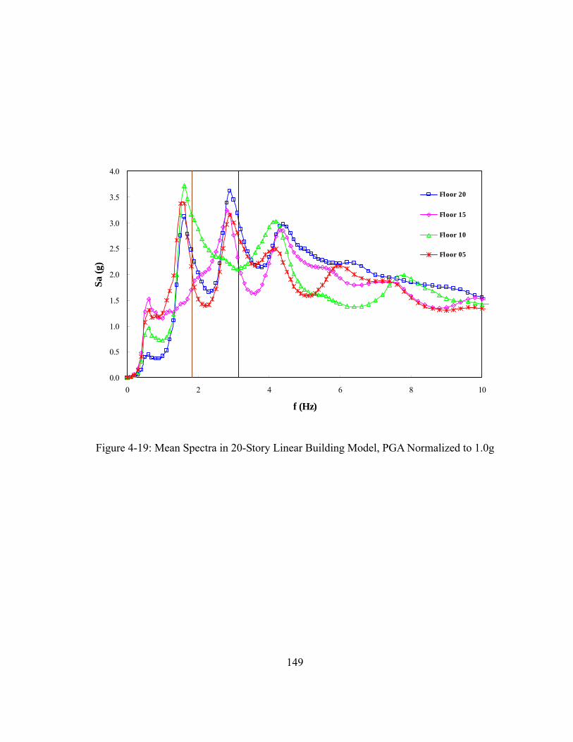
149
0.0
0.5
1.0
1.5
2.0
2.5
3.0
3.5
4.0
0 2 4 6 8 10
f (Hz)
Sa
(g)
Floor 20
Floor 15
Floor 10
Floor 05
Figure 4-19: Mean Spectra in 20-Story Linear Building Model, PGA Normalized to 1.0g

150
0.0
0.5
1.0
1.5
2.0
2.5
3.0
3.5
4.0
4.5
5.0
0 5 10 15
f (Hz)
Sa
(g)
Floor 01
Floor 02
Floor 03
Floor 04
Floor 05
Figure 4-20: Mean Spectra in 5-Story Nonlinear Building Model, PGA Normalized to 1.0g

151
0.0
0.5
1.0
1.5
2.0
2.5
3.0
3.5
4.0
4.5
5.0
0 5 10 15
f (Hz)
Sa
(g)
Floor 01
Floor 02
Floor 03
Floor 04
Floor 05
Figure 4-21: Mean Spectra in 5-Story Linear Building Model, PGA Normalized to 1.0g

152
Figure 4-22: Moment-Rotation Curves at the 1st Floor in 20-Story Nonlinear Building Model, PGA Normalized to 1.0g
-0.01 -0.005 0 0.005 0.01-3
-2
-1
0
1
2
3x 10
4
Rotation()
Mom
ent(l
b-in)
EQ01
-6 -4 -2 0 2 4
x 10-3
-2
-1
0
1
2x 10
4
Rotation()
Mom
ent(l
b-in
)
EQ02
-6 -4 -2 0 2 4
x 10-3
-2
-1
0
1
2x 10
4
Rotation()
Mom
ent(l
b-in
)
EQ03
-0.015 -0.01 -0.005 0 0.005 0.01-3
-2
-1
0
1
2
3x 10
4
Rotation()
Mom
ent(l
b-in)
EQ04
-0.015 -0.01 -0.005 0 0.005 0.01-3
-2
-1
0
1
2
3x 10
4
Rotation()
Mom
ent(l
b-in)
EQ05
-10 -5 0 5
x 10-3
-2
-1
0
1
2
3x 10
4
Rotation()
Mom
ent(l
b-in
)
EQ06
-15 -10 -5 0 5
x 10-3
-3
-2
-1
0
1
2
3x 10
4
Rotation()
Mom
ent(l
b-in
)
EQ07
-5 0 5 10 15
x 10-3
-3
-2
-1
0
1
2
3x 10
4
Rotation()
Mom
ent(l
b-in)
EQ08

153
Figure 4-23: Moment-Rotation Curves at the 1st Floor in 20-Story Nonlinear Building Model, PGA Normalized to 1.0g
-0.01 -0.005 0 0.005 0.01-3
-2
-1
0
1
2
3x 10
4
Rotation()
Mom
ent(l
b-in
)
EQ09
-4 -2 0 2 4 6
x 10-3
-2
-1
0
1
2
3x 10
4
Rotation()
Mom
ent(l
b-in
)
EQ10
-0.02 -0.01 0 0.01 0.02-3
-2
-1
0
1
2
3x 10
4
Rotation()
Mom
ent(l
b-in)
EQ11
-6 -4 -2 0 2 4
x 10-3
-2
-1
0
1
2x 10
4
Rotation()
Mom
ent(l
b-in
)
EQ12
-6 -4 -2 0 2 4
x 10-3
-2
-1
0
1
2
3x 10
4
Rotation()
Mom
ent(l
b-in
)
EQ13
-4 -2 0 2 4 6
x 10-3
-2
-1
0
1
2
3x 10
4
Rotation()
Mom
ent(l
b-in
)
EQ14
-10 -5 0 5
x 10-3
-3
-2
-1
0
1
2
3x 10
4
Rotation()
Mom
ent(l
b-in)
EQ15
-15 -10 -5 0 5
x 10-3
-3
-2
-1
0
1
2
3x 10
4
Rotation()
Mom
ent(l
b-in
)
EQ16

154
Figure 4-24: Moment-Rotation Curves at the 1st Floor in 20-Story Nonlinear Building Model, PGA Normalized to 1.0g
-10 -5 0 5
x 10-3
-3
-2
-1
0
1
2
3x 10
4
Rotation()
Mom
ent(l
b-in
)
EQ17
-4 -2 0 2 4 6
x 10-3
-2
-1
0
1
2
3x 10
4
Rotation()
Mom
ent(l
b-in
)
EQ18
-0.04 -0.03 -0.02 -0.01 0 0.01 0.02-3
-2
-1
0
1
2
3x 10
4
Rotation()
Mom
ent(l
b-in)
EQ19
-6 -4 -2 0 2 4 6
x 10-3
-3
-2
-1
0
1
2
3x 10
4
Rotation()
Mom
ent(l
b-in
)
EQ20
-10 -5 0 5
x 10-3
-3
-2
-1
0
1
2
3x 10
4
Rotation()
Mom
ent(l
b-in
)
EQ21
-0.01 -0.005 0 0.005 0.01-3
-2
-1
0
1
2
3x 10
4
Rotation()
Mom
ent(l
b-in)
EQ22

155
Figure 4-25: Moment-Rotation Curves at the 10th Floor in 20-Story Nonlinear Building Model, PGA Normalized to 1.0g
-0.01 -0.005 0 0.005 0.01-3
-2
-1
0
1
2
3x 10
4
Rotation()
Mom
ent(l
b-in
)
EQ01
-0.01 -0.005 0 0.005 0.01-3
-2
-1
0
1
2
3x 10
4
Rotation()
Mom
ent(l
b-in)
EQ02
-10 -5 0 5
x 10-3
-2
-1
0
1
2x 10
4
Rotation()
Mom
ent(l
b-in)
EQ03
-0.02 -0.01 0 0.01 0.02-3
-2
-1
0
1
2
3x 10
4
Rotation()
Mom
ent(l
b-in)
EQ04
-0.02 -0.01 0 0.01-3
-2
-1
0
1
2
3x 10
4
Rotation()
Mom
ent(l
b-in
)
EQ05
-0.01 -0.005 0 0.005 0.01-3
-2
-1
0
1
2
3x 10
4
Rotation()
Mom
ent(l
b-in)
EQ06
-0.01 -0.005 0 0.005 0.01-3
-2
-1
0
1
2
3x 10
4
Rotation()
Mom
ent(l
b-in)
EQ07
-0.01 0 0.01 0.02-3
-2
-1
0
1
2
3x 10
4
Rotation()
Mom
ent(l
b-in)
EQ08

156
Figure 4-26: Moment-Rotation Curves at the 10th Floor in 20-Story Nonlinear Building Model, PGA Normalized to 1.0g
-0.01 -0.005 0 0.005 0.01 0.015-3
-2
-1
0
1
2
3x 10
4
Rotation()
Mom
ent(l
b-in
)
EQ09
-0.01 -0.005 0 0.005 0.01-3
-2
-1
0
1
2
3x 10
4
Rotation()
Mom
ent(l
b-in
)
EQ10
-0.02 -0.01 0 0.01 0.02-3
-2
-1
0
1
2
3x 10
4
Rotation()
Mom
ent(l
b-in
)
EQ11
-0.01 -0.005 0 0.005 0.01-3
-2
-1
0
1
2
3x 10
4
Rotation()
Mom
ent(l
b-in
)
EQ12
-10 -5 0 5
x 10-3
-3
-2
-1
0
1
2
3x 10
4
Rotation()
Mom
ent(l
b-in
)
EQ13
-5 0 5
x 10-3
-2
-1
0
1
2
3x 10
4
Rotation()
Mom
ent(l
b-in
)
EQ14
-0.01 -0.005 0 0.005 0.01-3
-2
-1
0
1
2
3x 10
4
Rotation()
Mom
ent(l
b-in
)
EQ15
-10 -5 0 5
x 10-3
-3
-2
-1
0
1
2
3x 10
4
Rotation()
Mom
ent(l
b-in
)
EQ16
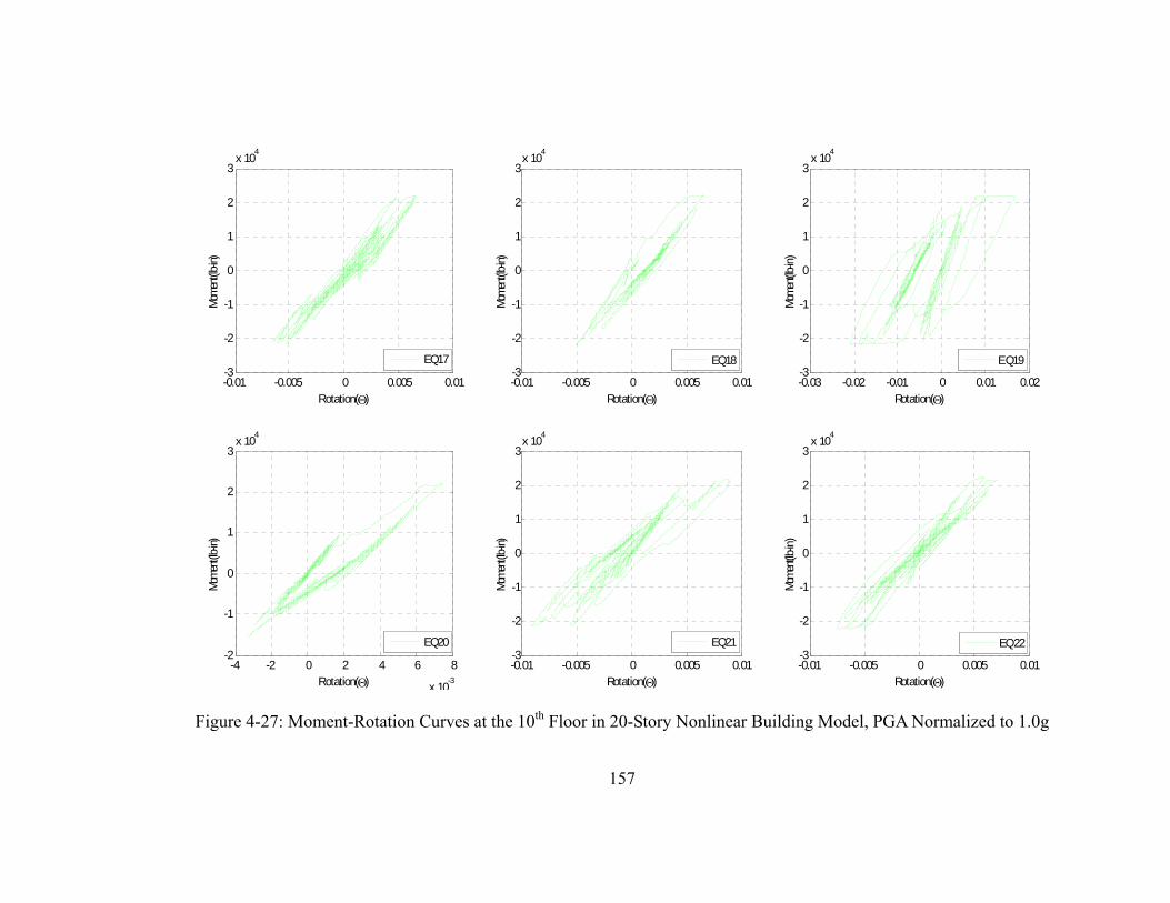
157
Figure 4-27: Moment-Rotation Curves at the 10th Floor in 20-Story Nonlinear Building Model, PGA Normalized to 1.0g
-0.01 -0.005 0 0.005 0.01-3
-2
-1
0
1
2
3x 10
4
Rotation()
Mom
ent(l
b-in)
EQ17
-0.01 -0.005 0 0.005 0.01-3
-2
-1
0
1
2
3x 10
4
Rotation()
Mom
ent(l
b-in)
EQ18
-0.03 -0.02 -0.01 0 0.01 0.02-3
-2
-1
0
1
2
3x 10
4
Rotation()
Mom
ent(lb
-in)
EQ19
-4 -2 0 2 4 6 8
x 10-3
-2
-1
0
1
2
3x 10
4
Rotation()
Mom
ent(l
b-in)
EQ20
-0.01 -0.005 0 0.005 0.01-3
-2
-1
0
1
2
3x 10
4
Rotation()
Mom
ent(l
b-in)
EQ21
-0.01 -0.005 0 0.005 0.01-3
-2
-1
0
1
2
3x 10
4
Rotation()
Mom
ent(lb
-in)
EQ22

158
Figure 4-28: Moment-Rotation Curves at the 20th Floor in 20-Story Nonlinear Building Model, PGA Normalized to 1.0g
-0.015 -0.01 -0.005 0 0.005 0.01-1.5
-1
-0.5
0
0.5
1
1.5x 10
4
Rotation()
Mom
ent(l
b-in
)
EQ01
-0.01 -0.005 0 0.005 0.01-1.5
-1
-0.5
0
0.5
1
1.5x 10
4
Rotation()
Mom
ent(l
b-in
)
EQ02
-10 -5 0 5
x 10-3
-1
-0.5
0
0.5
1x 10
4
Rotation()
Mom
ent(l
b-in
)
EQ03
-0.01 -0.005 0 0.005 0.01-1.5
-1
-0.5
0
0.5
1
1.5x 10
4
Rotation()
Mom
ent(l
b-in
)
EQ04
-0.02 -0.01 0 0.01-1.5
-1
-0.5
0
0.5
1x 10
4
Rotation()
Mom
ent(l
b-in
)
EQ05
-15 -10 -5 0 5
x 10-3
-1.5
-1
-0.5
0
0.5
1x 10
4
Rotation()
Mom
ent(l
b-in
)
EQ06
-0.01 -0.005 0 0.005 0.01-1.5
-1
-0.5
0
0.5
1
1.5x 10
4
Rotation()
Mom
ent(l
b-in
)
EQ07
-0.01 -0.005 0 0.005 0.01-1.5
-1
-0.5
0
0.5
1x 10
4
Rotation()
Mom
ent(l
b-in
)
EQ08

159
Figure 4-29: Moment-Rotation Curves at the 20th Floor in 20-Story Nonlinear Building Model, PGA Normalized to 1.0g
-0.015 -0.01 -0.005 0 0.005 0.01-1.5
-1
-0.5
0
0.5
1x 10
4
Rotation()
Mom
ent(l
b-in
)
EQ09
-5 0 5 10
x 10-3
-1
-0.5
0
0.5
1x 10
4
Rotation()
Mom
ent(l
b-in
)
EQ10
-0.01 -0.005 0 0.005 0.01 0.015-1
-0.5
0
0.5
1
1.5x 10
4
Rotation()
Mom
ent(l
b-in
)
EQ11
-5 0 5 10 15
x 10-3
-1
-0.5
0
0.5
1
1.5x 10
4
Rotation()
Mom
ent(l
b-in
)
EQ12
-0.01 -0.005 0 0.005 0.01-1.5
-1
-0.5
0
0.5
1x 10
4
Rotation()
Mom
ent(l
b-in
)
EQ13
-5 0 5 10
x 10-3
-1
-0.5
0
0.5
1
1.5x 10
4
Rotation()
Mom
ent(l
b-in
)
EQ14
-0.01 -0.005 0 0.005 0.01-1
-0.5
0
0.5
1x 10
4
Rotation()
Mom
ent(l
b-in
)
EQ15
-0.01 -0.005 0 0.005 0.01-1
-0.5
0
0.5
1
1.5x 10
4
Rotation()
Mom
ent(l
b-in
)
EQ16

160
Figure 4-30: Moment-Rotation Curves at the 20th Floor in 20-Story Nonlinear Building Model, PGA Normalized to 1.0g
-0.01 -0.005 0 0.005 0.01 0.015-1
-0.5
0
0.5
1
1.5x 10
4
Rotation()
Mom
ent(l
b-in
)
EQ17
-5 0 5 10 15
x 10-3
-1
-0.5
0
0.5
1
1.5x 10
4
Rotation()
Mom
ent(l
b-in
)
EQ18
-0.02 -0.015 -0.01 -0.005 0 0.005 0.01-1.5
-1
-0.5
0
0.5
1x 10
4
Rotation()
Mom
ent(l
b-in
)
EQ19
-5 0 5 10
x 10-3
-1
-0.5
0
0.5
1x 10
4
Rotation()
Mom
ent(l
b-in
)
EQ20
-0.015 -0.01 -0.005 0 0.005 0.01-1.5
-1
-0.5
0
0.5
1x 10
4
Rotation()
Mom
ent(l
b-in
)
EQ21
-0.015 -0.01 -0.005 0 0.005 0.01-1.5
-1
-0.5
0
0.5
1
1.5x 10
4
Rotation()
Mom
ent(l
b-in
)
EQ22

161
Figure 4-31: Interstory Drift Ratio in 20-Story Nonlinear Building Model
0
1
2
3
4
5
6
7
8
9
10
11
12
13
14
15
16
17
18
19
20
0.00 0.01 0.02 0.03 0.04 0.05
Drift Ratio
Sto
ry L
evel
EQ01
EQ02
EQ03
EQ04
EQ05
EQ06
EQ07
EQ08
EQ09
EQ10
EQ11
EQ12
EQ13
EQ14
EQ16
EQ17
EQ18
EQ19
EQ20
EQ21
EQ22
MEAN

162
0.00
0.20
0.40
0.60
0.80
1.00
0.00 0.50 1.00 1.50 2.00 2.50 3.00
PGA (g)
Pf
Floor 20
Floor 15
Floor 10
Floor 05
Ground
Figure 4-32: Seismic Fragility of Piping System in 20-Story Nonlinear Building Model

163
0.00
0.20
0.40
0.60
0.80
1.00
0.00 0.50 1.00 1.50 2.00 2.50 3.00
PGA (g)
Pf
Floor 20
Floor 15
Floor 10
Floor 05
Ground
Figure 4-33: Seismic Fragilities of Piping System in 20-Story Linear Building Model

164
0.00
0.20
0.40
0.60
0.80
1.00
0.00 0.50 1.00 1.50 2.00 2.50 3.00
PGA (g)
Pf Linear
Nonlinear
Figure 4-34: Seismic Fragilities of Piping System at the 20th Floor in 20-Story Linear and
Nonlinear Building Models

165
0.00
0.20
0.40
0.60
0.80
1.00
0.00 0.50 1.00 1.50 2.00 2.50 3.00
PGA (g)
Pf
Linear
Nonlinear
Figure 4-35: Seismic Fragilities of Piping System at the 15th Floor in 20-Story Linear and
Nonlinear Building Models

166
0.00
0.20
0.40
0.60
0.80
1.00
0.00 0.50 1.00 1.50 2.00 2.50 3.00
PGA (g)
Pf
Linear
Nonlinear
Figure 4-36: Seismic Fragilities of Piping System at the 10th Floor in 20-Story Linear and
Nonlinear Building Models

167
0.00
0.20
0.40
0.60
0.80
1.00
0.00 0.50 1.00 1.50 2.00 2.50 3.00
PGA (g)
Pf
Linear
Nonlinear
Figure 4-37: Seismic Fragilities of Piping System at the 5th Floor in 20-Story Linear and
Nonlinear Building Models

168
0.00
0.20
0.40
0.60
0.80
1.00
0.0 0.5 1.0 1.5 2.0 2.5 3.0
PGA (g)
Pf
Floor 01
Floor 02
Floor 03
Floor 04
Floor 05
Figure 4-38: Seismic Fragilities of Piping System in 5-Story Linear Building Model

169
0.00
0.20
0.40
0.60
0.80
1.00
0.00 0.50 1.00 1.50 2.00 2.50 3.00
PGA (g)
Pf
Floor 01
Floor 02
Floor 03
Floor 04
Floor 05
Figure 4-39: Seismic Fragilities of Piping System in 5-Story Nonlinear Building Model

170
PART V
SUMMARY AND CONCLUSIONS
171
1. SUMMARY AND CONCLUSIONS
This dissertation presents the results of a detailed study that focuses on the
evaluation of system level fragilities in the piping system with threaded Tee-joints. The two
main aspects of this study focus on (a) developing a framework to incorporate the lessons
learned from component level testing of threaded Tee-joint into a system level piping
analysis, and (b) the effect of building performance on the piping fragilities. The summary
and main conclusions for each part are given below.
(i) FRAGILITY OF PIPING SYSTEMS WITH THREADED TEE-JOINTS
The cost of damage to the non-structural systems and components can exceed 80% of
the total damages during an earthquake. Many existing studies and ATC-58 (2004) highlight
the need for performance based design and probabilistic approaches to mitigate risk and to
achieve reliable designs. This study focuses on evaluating the seismic fragilities of threaded
T- joint connection in sprinkler piping systems.
Often, threaded connections in piping tend to exhibit complex nonlinear behavior
under dynamic loading. Simple laboratory tests of the threaded connections under monotonic
and cyclic loading can give us insights into the behavior and the typical performance
characteristics. Test data can be used to characterize the limit states as well as obtain
nonlinear force-displacement and moment-rotation relationships at locations around the
connection. This can be used to create a relatively simple non-linear finite element model for

172
seismic fragility evaluations.
The University at Buffalo, SUNY conducted laboratory tests on various threaded
Tee-joint components of sprinkler piping systems. The tests indicate that the "First Leak"
damage state is observed predominantly due to excessive flexural deformations at the Tee-
joint section. We use the monotonic and cyclic loading test data to characterize the limit state
corresponding to “First Leak” for a 2 inch black iron threaded Tee-joint connection and to
develop a simple nonlinear finite element model describing the Tee-joint behavior.
The nonlinear FE model developed is then used in conjunction with the main line of
a typical hospital floor piping to obtain system-level fragilities corresponding to the first leak
damage state. A total of 75 real normalized earthquake records are used to describe the
uncertainty in ground motion histories. In addition, the system fragility is evaluated by
considering two different types of threaded Tee-joint connections i.e. monotonic FE model
and cyclic FE model. The fragility curves are generated for failure at a single critical location
as well as multiple possible failure locations. The seismic fragility curves of the Tee-joint
system at each location are significantly different for the two different FE models considered.
Consequently, it is suggested that the threaded Tee-joint connection based on cyclic FE
model be used to evaluate the system-level fragility at each critical location.
It is also illustrated that the system fragilities corresponding to the same limit state is
significantly different when evaluated from a decoupled analysis of just the Tee-joint
assembly component. Therefore, interaction and tuning between the main line piping and the
branch piping can have a considerable effect on seismic fragilities.
173
(ii) PIPING FRAGILITY EVALUATION: INTERACTION WITH BUILDING
PERFORMANCE
This paper presents the results of a detailed study on the evaluation of piping system
fragility curves by incorporating the nonlinear moment-rotation characteristics of a 2-inch
threaded Tee-joint of a black iron pipe in the system level piping model. The particular focus
is on the evaluating the effect of interaction between the building and the piping on the
piping fragility. The effect of building behavior is included by considering low rise 5-story
and high rise 20-story building models. For each of the two building models, piping
fragilities are evaluated by considering the building to exhibit significant nonlinearity in the
beams and columns as well as by considering the buildings to remain linear for each of the
22 real ground motion records. In order to consider the effect of nonlinearity in building
model, the ground motion records are taken from relatively larger magnitude earthquakes
(greater than 6) that are recorded in different parts of the world. It is observed that the
fundamental building mode is not necessarily critical contributing mode in the evaluation of
piping fragilities. Same is true for the fundamental piping system mode. Since piping system
modes are local in nature, the piping mode that causes excitation around the location of the
critical component such as the threaded Tee-joints governs the piping performance.
Furthermore, the building mode with frequency closest to the governing piping system mode
influences the piping system fragility more critically. It is also observed that the piping
system fragilities can be higher in a linear building model whose modes have greater degree
of tuning with the piping system modes. However, in some cases the piping system fragility

174
can be higher for the nonlinear building models if the nonlinearity increases the degree of
tuning between the piping and the building modes. The piping fragility does not necessarily
increases with the increasing floor levels in a high rise building. The product of modal
participation factor and the mode shape ordinate in the most critical building mode gives a
good estimate of the relative amplification at different floor levels and consequently the
relative increase or decrease in the piping fragility. Finally, it must be noted that as the degree
of degradation in a nonlinear building model increases with increasing values of the peak
ground accelerations, the effect of tuning between the building and the piping modes can
either increase or decrease. Such a variation in the degree of tuning leads to a corresponding
change in the piping fragility.

175
2. RECOMMENDATIONS FOR FUTURE RESEARCH
The research presented in this dissertation is a first step towards exploring the subject of
system-level piping fragilities in buildings and other critical facilities. Based on the
experience gained in conducting this research, a few recommendations for future work in this
area are summarized below.
Additional verification and validation work is needed for threaded Tee-joints
of different diameters. Experimental data from the tests performed at UB for
other pipe diameters should be used to conduct these additional verification
studies.
University at Buffalo is currently in the process of completing laboratory
testing of a sub-branch piping system at two different floor levels connected
with a riser. This sub-system consists of threaded Tee-joint connections for
different diameter pipes. A comparison of FE model for this system with the
experimental results and subsequent evaluation of piping fragility will be
quite instrumental in improving the confidence of this work.
Preliminary testing of subsystems at UB have shown that ceiling tile systems
attached to the sprinkler heads can influence the performance of piping
systems. Therefore, future research should consider the interaction of ceiling
system and sprinkler heads within the sub-branch system to evaluate the
effect of ceiling system on piping fragility.

176
Evaluate the fragility of sub-branch piping system based on the multiple
possible failure locations.
A coupled analysis of the building and piping systems along with non-
classical damping should be considered.
It would be good to explore the development of simpler methodology for
evaluating approximate but reasonable estimates of piping fragility without
actually conducting a detailed nonlinear simulation using multiple time
history analyses.