julabo/ika i/o driver programmable serial interface card · powerful solutions for digital plants...
TRANSCRIPT

Julabo/IKA I/O Driver Programmable Serial Interface Card
USER MANUAL
Rev. P1.57
December 17, 2014
DeltaV is a trademark of Emerson Process Management, Inc © Emerson Process Management, Inc. 1998, 1999.
All rights reserved. Printed in the U.S.A. While this information is presented in good faith and believed to be accurate, Munger Co., Inc. does not guarantee
satisfactory results from reliance upon such information. Nothing contained herein is to be construed as a warranty or guarantee, express or implied, regarding the performance, merchantability, fitness or any other matter with respect to the products, nor as a recommendation to use any product or process in conflict with any patent. Munger Co., Inc. reserves the right, without notice, to alter or improve the designs or specifications of the products described herein.

Powerful Solutions for Digital Plants
MYNAH Technologies ● 390 South Woods Mill Rd., Suite 100 ● Chesterfield, MO 63017 ● Telephone 636 728-2000
www.mynah.com
1
1 INTRODUCTION
1.1 Scope This document is the User Manual for the Julabo and IKA I/O serial communication driver
firmware for the Emerson Process Management (EPM) DeltaV Control System; it provides information required to install, configure, and maintain the driver firmware on the DeltaV Programmable Serial Interface Card (PSIC). The reader should be familiar with EPM’s DeltaV and field devices (supporting the Julabo and/or IKA protocol) connected to the PSIC.
The section Document Format briefly describes the contents of each section of this manual.
System Specifications outlines hardware and software requirements for the Julabo/IKA I/O Driver (P1.55 or later) firmware.
1.2 Document Format This document is organized as follows:
Introduction Describes the scope and purpose of this document.
Theory of Operation Provides a general functional overview of the Julabo/IKA I/O Driver.
Downloading Firmware Describes downloading procedures for the Julabo/IKA I/O Driver firmware on to the DeltaV PSIC.
Configuration Information Describes procedures and guidelines for configuring the DeltaV PSIC.
Operational Check Provides tips and assistance to ensure PSIC is properly setup and configured.
DeltaV–Field Device Electrical Interface
Describes the electrical interface between DeltaV and the Field Device. Also describes the pin assignments for RS-232 communications.
Technical Support Describes who to call if you need assistance.
Example
Example configuration for a Serial Card and referencing modules is included in the distribution.

Powerful Solutions for Digital Plants
MYNAH Technologies ● 390 South Woods Mill Rd., Suite 100 ● Chesterfield, MO 63017 ● Telephone 636 728-2000
www.mynah.com
2
1.3 System Specifications The following table lists the minimum system requirements for the Julabo/IKA I/O Driver: Table 1: System Specifications
Firmware Julabo/IKA I/O Driver Firmware (P1.55)
Protocol Compatibility Julabo Protocol is based on publication 1.953.1221BU2, dated 02/01. IKA protocol is based on publication EUROST0795EU.
Software Requirements DeltaV System Software (Release 4.2 or later) installed on a hardware-appropriate Windows NT workstation configured as a ProfessionalPlus for DeltaV
Serial Interface Port License (VE4102) if required
Minimum DeltaV Hardware Requirements
DeltaV Series 1 Serial Module, Hardware Rev 1.1r
DeltaV MD, MD Plus, MX or SX Controller, Power Supply and 8 wide controller carrier
1.4 Release Notes for v1.55
� This release is a rebuild of v1.12 under the new Emerson driver toolkit v3.01. There are no other changes.
1.5 Release Notes for v1.57
� Added ability to read maximum of 16 input parameters. Added mechanism to skip reading parameters which are not supported by the particular Julabo device.

Powerful Solutions for Digital Plants
MYNAH Technologies ● 390 South Woods Mill Rd., Suite 100 ● Chesterfield, MO 63017 ● Telephone 636 728-2000
www.mynah.com
3
2 THEORY OF OPERATION As part of the serial interface port license, a standard Modbus protocol is installed on the
DeltaV PSIC prior to customization. The PSIC needs to be flash upgraded from the Modbus protocol to the Julabo/IKA I/O firmware before operation.
The Programmable Serial Interface Card (PSIC) supports RS-232, RS-422/RS-485 Half Duplex and RS-422/RS-485 Full Duplex communications with external devices. For communications with Julabo/IKA devices, only RS-232 can be utilized. The electrical connection and communication settings must be configured properly to ensure accurate communication between the PSIC and field devices. These are described in Section 4.1.
The primary functions of the driver are listed below:
• Performs data and message handling between DeltaV and field devices.
• The driver runs in Master mode only. It sends read/write commands to the field device, checks validity of responses received, and updates the corresponding DeltaV PSIC registers.
Each PSIC, when loaded with the Julabo/IKA I/O Driver, is capable of communicating with field devices over one or both of its two ports, depending upon your application. Specifically, both ports can be configured for Julabo, IKA, or one of each. Note: This driver runs in Simplex mode only.
Powerful Solutions for Digital Plants
MYNAH Technologies ● 390 South Woods Mill Rd., Suite 100 ● Chesterfield, MO 63017 ● Telephone 636 728-2000
www.mynah.com
4
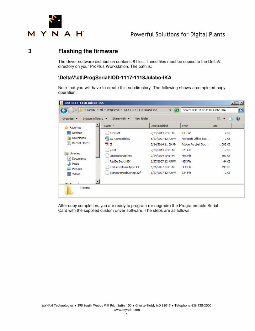
3 Flashing the firmware
The driver software distribution contains 8 files. These files must be copied to the DeltaV
directory on your ProPlus Workstation. The path is:
\DeltaV\ctl\ProgSerial\IOD-1117-1118Julabo-IKA
Note that you will have to create this subdirectory. The following shows a completed copy operation:
After copy completion, you are ready to program (or upgrade) the Programmable Serial Card with the supplied custom driver software. The steps are as follows:
Powerful Solutions for Digital Plants
MYNAH Technologies ● 390 South Woods Mill Rd., Suite 100 ● Chesterfield, MO 63017 ● Telephone 636 728-2000
www.mynah.com
5
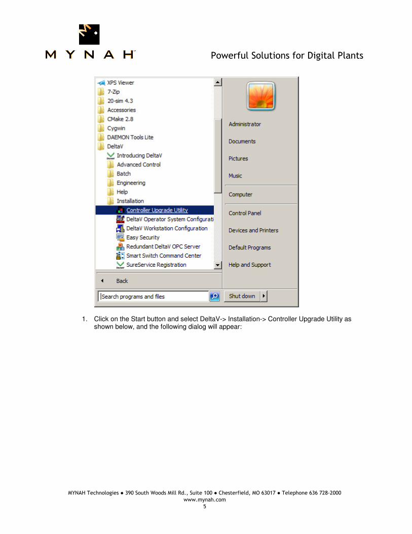
1. Click on the Start button and select DeltaV-> Installation-> Controller Upgrade Utility as shown below, and the following dialog will appear:

Powerful Solutions for Digital Plants
MYNAH Technologies ● 390 South Woods Mill Rd., Suite 100 ● Chesterfield, MO 63017 ● Telephone 636 728-2000
www.mynah.com
6
2. Select I/O Modules in the list, then click Next.

Powerful Solutions for Digital Plants
MYNAH Technologies ● 390 South Woods Mill Rd., Suite 100 ● Chesterfield, MO 63017 ● Telephone 636 728-2000
www.mynah.com
7
3. The above dialog will appear, listing all the available Controllers in your network. From
this dialog, select the appropriate Controller and then Click Next.
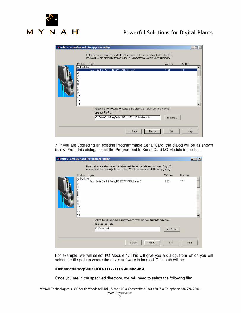
4. The following dialog will appear, listing all the I/O modules in your selected Controller.
The shown list of I/O modules is an example only. Your list will be different. Note: The first time a standard Serial card is upgraded to the Julabo/IKA I/O Driver,
the dialog will be as shown below. When upgrading an existing Programmable Serial Card, skip Steps 5 and 6, and go to Step 7.
Powerful Solutions for Digital Plants
MYNAH Technologies ● 390 South Woods Mill Rd., Suite 100 ● Chesterfield, MO 63017 ● Telephone 636 728-2000
www.mynah.com
8
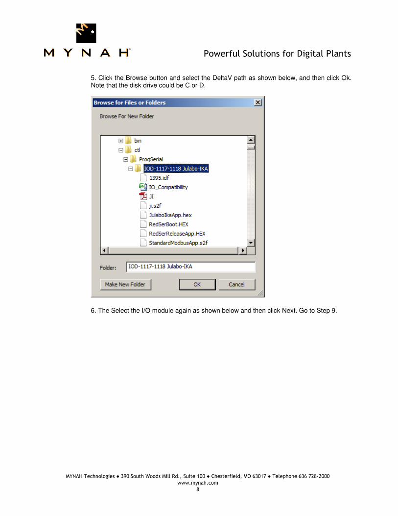
5. Click the Browse button and select the DeltaV path as shown below, and then click Ok. Note that the disk drive could be C or D.
6. The Select the I/O module again as shown below and then click Next. Go to Step 9.
Powerful Solutions for Digital Plants
MYNAH Technologies ● 390 South Woods Mill Rd., Suite 100 ● Chesterfield, MO 63017 ● Telephone 636 728-2000
www.mynah.com
9
7. If you are upgrading an existing Programmable Serial Card, the dialog will be as shown below. From this dialog, select the Programmable Serial Card I/O Module in the list.
For example, we will select I/O Module 1. This will give you a dialog, from which you will
select the file path to where the driver software is located. This path will be: \DeltaV\ctl\ProgSerial\IOD-1117-1118 Julabo-IKA Once you are in the specified directory, you will need to select the following file:

Powerful Solutions for Digital Plants
MYNAH Technologies ● 390 South Woods Mill Rd., Suite 100 ● Chesterfield, MO 63017 ● Telephone 636 728-2000
www.mynah.com
10
JI.SDF
This is shown in the following dialog.
Powerful Solutions for Digital Plants
MYNAH Technologies ● 390 South Woods Mill Rd., Suite 100 ● Chesterfield, MO 63017 ● Telephone 636 728-2000
www.mynah.com
11
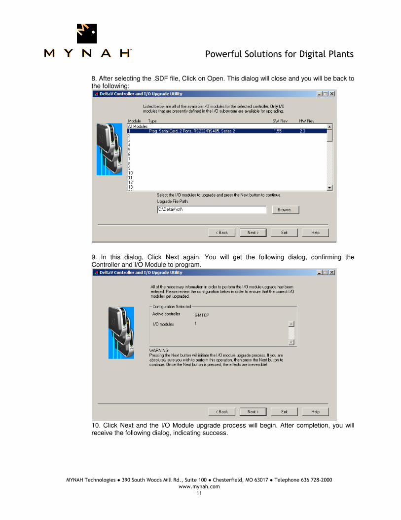
8. After selecting the .SDF file, Click on Open. This dialog will close and you will be back to the following:
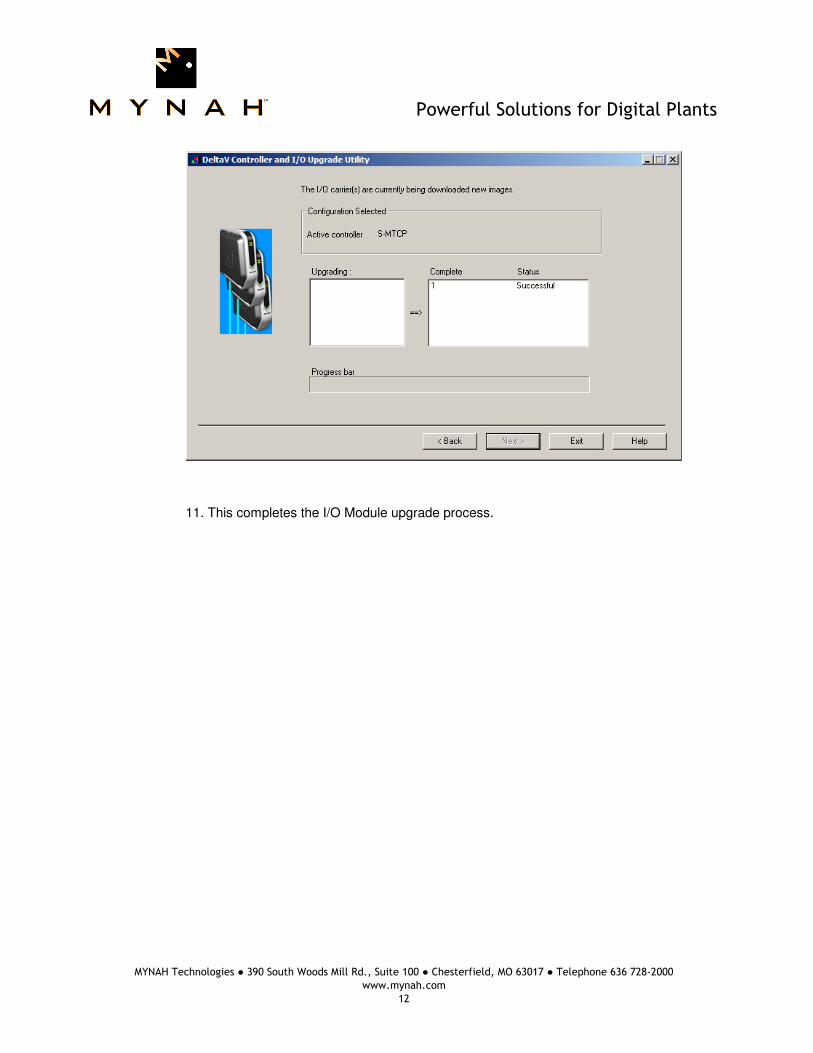
9. In this dialog, Click Next again. You will get the following dialog, confirming the Controller and I/O Module to program.
10. Click Next and the I/O Module upgrade process will begin. After completion, you will receive the following dialog, indicating success.
Powerful Solutions for Digital Plants
MYNAH Technologies ● 390 South Woods Mill Rd., Suite 100 ● Chesterfield, MO 63017 ● Telephone 636 728-2000
www.mynah.com
12
11. This completes the I/O Module upgrade process.
Powerful Solutions for Digital Plants
MYNAH Technologies ● 390 South Woods Mill Rd., Suite 100 ● Chesterfield, MO 63017 ● Telephone 636 728-2000
www.mynah.com
13
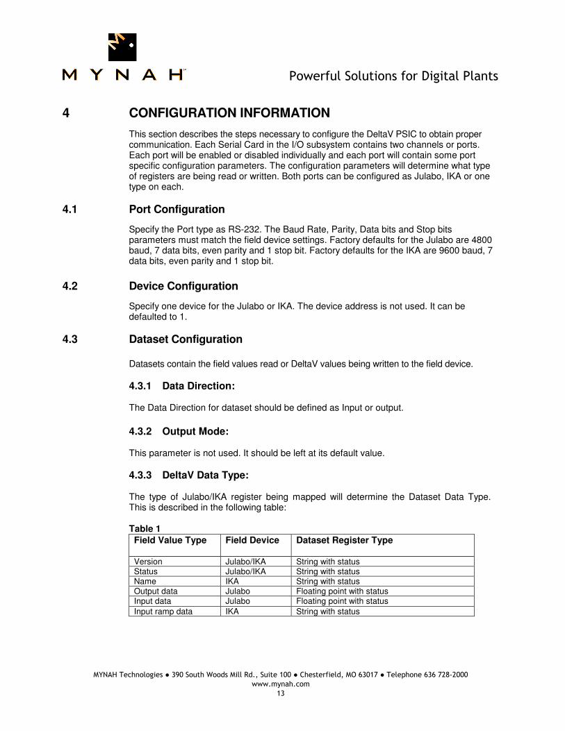
4 CONFIGURATION INFORMATION
This section describes the steps necessary to configure the DeltaV PSIC to obtain proper communication. Each Serial Card in the I/O subsystem contains two channels or ports. Each port will be enabled or disabled individually and each port will contain some port specific configuration parameters. The configuration parameters will determine what type of registers are being read or written. Both ports can be configured as Julabo, IKA or one type on each.
4.1 Port Configuration
Specify the Port type as RS-232. The Baud Rate, Parity, Data bits and Stop bits parameters must match the field device settings. Factory defaults for the Julabo are 4800 baud, 7 data bits, even parity and 1 stop bit. Factory defaults for the IKA are 9600 baud, 7 data bits, even parity and 1 stop bit.
4.2 Device Configuration
Specify one device for the Julabo or IKA. The device address is not used. It can be defaulted to 1.
4.3 Dataset Configuration Datasets contain the field values read or DeltaV values being written to the field device.
4.3.1 Data Direction: The Data Direction for dataset should be defined as Input or output.
4.3.2 Output Mode: This parameter is not used. It should be left at its default value.
4.3.3 DeltaV Data Type: The type of Julabo/IKA register being mapped will determine the Dataset Data Type. This is described in the following table: Table 1
Field Value Type Field Device Dataset Register Type
Version Julabo/IKA String with status Status Julabo/IKA String with status Name IKA String with status Output data Julabo Floating point with status Input data Julabo Floating point with status
Input ramp data IKA String with status
Powerful Solutions for Digital Plants
MYNAH Technologies ● 390 South Woods Mill Rd., Suite 100 ● Chesterfield, MO 63017 ● Telephone 636 728-2000
www.mynah.com
14
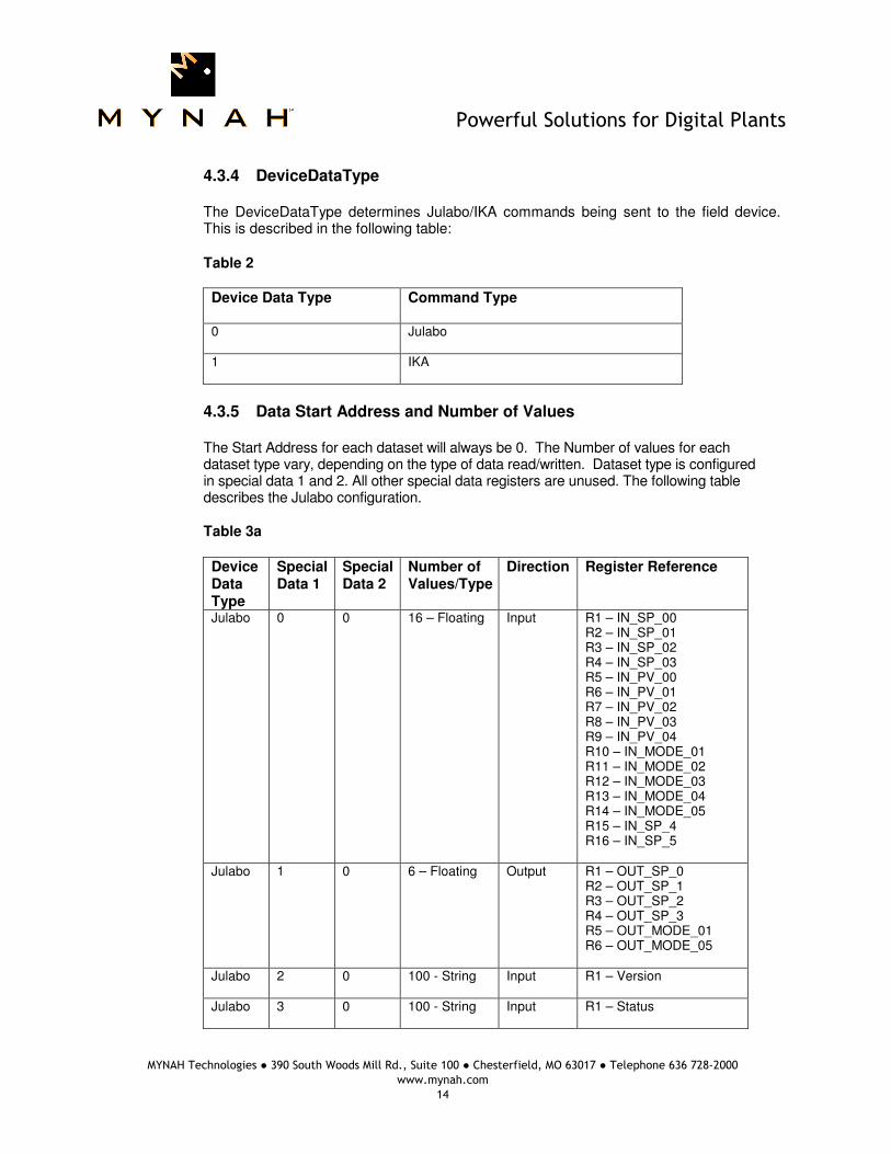
4.3.4 DeviceDataType The DeviceDataType determines Julabo/IKA commands being sent to the field device. This is described in the following table: Table 2
Device Data Type Command Type
0
Julabo
1
IKA
4.3.5 Data Start Address and Number of Values The Start Address for each dataset will always be 0. The Number of values for each dataset type vary, depending on the type of data read/written. Dataset type is configured in special data 1 and 2. All other special data registers are unused. The following table describes the Julabo configuration. Table 3a
Device Data Type
Special Data 1
Special Data 2
Number of Values/Type
Direction Register Reference
Julabo 0 0 16 – Floating
Input
R1 – IN_SP_00 R2 – IN_SP_01 R3 – IN_SP_02 R4 – IN_SP_03 R5 – IN_PV_00 R6 – IN_PV_01 R7 – IN_PV_02 R8 – IN_PV_03 R9 – IN_PV_04 R10 – IN_MODE_01 R11 – IN_MODE_02 R12 – IN_MODE_03 R13 – IN_MODE_04 R14 – IN_MODE_05 R15 – IN_SP_4 R16 – IN_SP_5
Julabo
1
0 6 – Floating
Output
R1 – OUT_SP_0 R2 – OUT_SP_1 R3 – OUT_SP_2 R4 – OUT_SP_3 R5 – OUT_MODE_01 R6 – OUT_MODE_05
Julabo
2
0 100 - String
Input
R1 – Version
Julabo
3 0 100 - String
Input
R1 – Status
Powerful Solutions for Digital Plants
MYNAH Technologies ● 390 South Woods Mill Rd., Suite 100 ● Chesterfield, MO 63017 ● Telephone 636 728-2000
www.mynah.com
15
Julabo Input Scan Control Julabo Input data registers are specific for various versions of the device. Not all devices support all these parameters. The driver is designed to allow you to configure the input scan to skip parameters which are unavailable. Special Data 5 is a 16-bit mask with a default value of 0. Each bit enables or disables scan of the corresponding register, i.e., all registers are scan enabled by default. A bit value of 1 disables the individual registers can. For example, in the above register list, Special Data 5 value of 56910 will disable the scan for Registers R2, R3, R4, R7, R10, R11, R12, R13, R15 and R16.
Powerful Solutions for Digital Plants
MYNAH Technologies ● 390 South Woods Mill Rd., Suite 100 ● Chesterfield, MO 63017 ● Telephone 636 728-2000
www.mynah.com
16
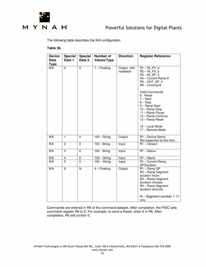
The following table describes the IKA configuration. Table 3b
Device Data Type
Special Data 1
Special Data 2
Number of Values/Type
Direction Register Reference
IKA 0 0 7 – Floating
Output with readback
R1 – IN_PV_4 R2 – IN_PV_5 R3 – IN_SP_4 R4 – Current Ramp # R5 – OUT_SP_4 R6 – Command Valid Commands: 6 - Reset 7 – Start 8 – Stop 9 – Ramp Start 10 – Ramp Stop 11 – Ramp Pause 12 – Ramp Continue 13 – Ramp Reset 16 – Local Mode 17 – Remote Mode
IKA
1
0 100 – String
Output
R1 – Device Name Not supported at this time.
IKA 2 0 100 - String
Input
R1 – Version
IKA
3 0 100 - String
Input
R1 – Status
IKA 4 0 100 – String Input R1 – Name IKA 5 0 100 – String Input R1 – Current Ramp
SP/Duration IKA 6 N 4 – Floating Output R1 – Ramp SP
R2 – Ramp Segment duration hours R3 – Ramp Segment duration minutes R4 – Ramp Segment duration seconds
N – Segment number 1-11 only
Commands are entered in R6 of the command dataset. After completion, the PSIC sets command register R6 to 0. For example, to send a Reset, enter 6 in R6. After completion, R6 will contain 0.

Powerful Solutions for Digital Plants
MYNAH Technologies ● 390 South Woods Mill Rd., Suite 100 ● Chesterfield, MO 63017 ● Telephone 636 728-2000
www.mynah.com
17
5 Operational Check
5.1 Scope The following sections provide some assistance to ensure the interface is working
properly.
5.2 Verify Hardware and Software Version Number
The user can verify that the Julabo/IKA I/O driver has been installed using the DeltaV Diagnostics tool. The Diagnostics tool will show the Hardware Revision No. (HwRev) and the Software Revision No. (SwRev).
To begin the DeltaV Diagnostic tool select Start-> DeltaV-> Operator-> Diagnostics. In
the Diagnostics tool expand the Controller, I/O and then double click on the Programmable Serial Interface Card that has the driver installed.
The following information will be displayed: : : : HwRev Hardware Revision 1.1 (or later) SwRev Software Revision P1.0 (or later)
5.3 Verify Configuration
• Verify port configuration: The serial port must be enabled. User needs to make sure communication settings such as baud rate, parity, and number of data bits match the field device settings.
• Verify dataset configuration: The datasets configured must be as shown above.
5.4 Verify I/O Communication With Control Studio User can create I/O modules in the control studio to verify correct values are read from the PSIC. For AI and DI data, the values should be changed in the field device and verified that the new data are correctly reported in DeltaV. Similarly, verify that the AO and DO data is being written correctly from DeltaV to the field device.

Powerful Solutions for Digital Plants
MYNAH Technologies ● 390 South Woods Mill Rd., Suite 100 ● Chesterfield, MO 63017 ● Telephone 636 728-2000
www.mynah.com
18
5.5 Using Diagnostics
• Verify PSIC communication: Select the PSIC on Diagnostics and press the right mouse button. Select Display Real -Time Statistics from the drop down menu. If the Programmable Serial Interface Card is functioning then the user will see the Valid Responses counter and the Async and/or Sync Transactions counters incrementing. There will not be any error counting up.
• Verify port statistics: Select the Port on the Programmable Serial Interface Card and press the right mouse button. Then select Display Port Statistics form the drop down menu. Verify that the port communications statistics are being displayed properly and are counting as expected for the protocol’s functionality.
• Verify dataset values: Select a dataset and press the right mouse button. Select View Dataset Registers from the Drop down window. Verify that the dataset values are displayed as expected.
5.6 LED Indication
The Yellow LED for the port should be on solid when all communications on that port are valid. The Yellow LED should be blinking if there is some valid communications and some communications with errors on that port. The Yellow LED should be OFF if there are no valid communications on that port.

Powerful Solutions for Digital Plants
MYNAH Technologies ● 390 South Woods Mill Rd., Suite 100 ● Chesterfield, MO 63017 ● Telephone 636 728-2000
www.mynah.com
19
6 DeltaV–Field Device Electrical Interface
The electrical interface between DeltaV and field devices conforms to the RS-232 and RS-422/485 standards. Each PSIC has 2 ports, which function independently. The distance between the serial card and the field device can be as much as 4000 feet, per the RS-422/485 standard. When using RS-232, the distance is limited to 50 feet. Section 6.1 shows the pin assignments for the PSIC serial terminal block.
6.1 Pin Assignments for DeltaV PSIC RS-232 Standard
Terminal Number Signal Description 1 Port 1 - Isolated Ground (GND) 2 Unused 3 Port 1 – Transmit Data (TxD) 4 Unused 5 Port 1 – Receive Data (RxD) 6 Unused 7 Port 1 – Data Terminal Ready (DTR) 8 Port 1 – Data Set Ready (DSR) 9 Port 2 - Isolated Ground (GND) 10 Unused 11 Port 2 – Transmit Data (TxD) 12 Unused 13 Port 2 – Receive Data (RxD) 14 Unused 15 Port 2 – Data Terminal Ready (DTR) 16 Port 1 – Data Set Ready (DSR)

Powerful Solutions for Digital Plants
MYNAH Technologies ● 390 South Woods Mill Rd., Suite 100 ● Chesterfield, MO 63017 ● Telephone 636 728-2000
www.mynah.com
20
RS-422/485 Half Duplex Standard
Terminal Number Signal Description 1 Port 1 - Isolated Ground (GND) 2 Port 1 - Data + 3 Unused 4 Port 1 - Data - 5 Unused 6 Unused 7 Unused 8 Unused 9 Port 2 - Isolated Ground (GND) 10 Port 2 – Data + 11 Unused 12 Port 2 - Data - 13 Unused 14 Unused 15 Unused 16 Unused
RS-422/485 Full Duplex Standard
Terminal Number Signal Description 1 Port 1 - Isolated Ground (GND) 2 Port 1 – TxD + 3 Unused 4 Port 1 – TxD - 5 Unused 6 Port 1 – RxD + 7 Unused 8 Port 1 – RxD - 9 Port 2 - Isolated Ground (GND) 10 Port 2 – TxD + 11 Unused 12 Port 2 – TxD - 13 Unused 14 Port 2 – RxD + 15 Unused 16 Port 2 – RxD -

Powerful Solutions for Digital Plants
MYNAH Technologies ● 390 South Woods Mill Rd., Suite 100 ● Chesterfield, MO 63017 ● Telephone 636 728-2000
www.mynah.com
21
6.2 Wiring Connections
In general, the figure below shows the connections between the Field Device and the PSIC termination block. In some cases, RxD and TxD signals need to be swapped to create a NULL cable. This can be done easily at the PSIC termination block.
Serial Card
Term. Block
IKA Device
15-Pin Port
(GND)
(TXD)
(RXD)
(DTR)
(DSR)
(GND)
(RXD)
(TXD)
(RTS)
(CTS)
9
13
11
15
16
1
5
3
2
7
8
1
3
5
7
8
P1 P2
Powerful Solutions for Digital Plants
MYNAH Technologies ● 390 South Woods Mill Rd., Suite 100 ● Chesterfield, MO 63017 ● Telephone 636 728-2000
www.mynah.com
22
7 Technical Support
For technical support or to report a defect, please give MYNAH Technologies a call at (636) 728-2000. If a defect is discovered, please document it in as much detail as possible and then fax your report to us at (636) 728-2001. You can also send us your questions via e-mail. Our addresses are: [email protected] Thank you for using DeltaV.