july 19, 2012 t. leveling 1 - fermilab muon department
TRANSCRIPT

July 19, 2012 T. Leveling 1
Hi all, I have posted the slides from the meeting yesterday on the TLM web page. The slides now include the text of this message. The following is a revised summary of what we discussed on July 18th. I have received comments from John and Sam (marked in red) and those have been incorporated into the original list. The TLM web site now includes chipmunk build documentation. Dan Schoo has provided a data sheet on very high value resistors for the TLM heartbeat which is also added to the TLM web page.
1. We should attend to the requirements of the engineering manual as we develop the TLM electrometer.
2. The electrometer duty factor must be 100%. There is no “off time”. 3. HV supply is required for each individual TLM. 4. Gas parameters are to be monitored by the RSS independent of the electrometer. 5. TLMs are to be gas tight; gas flow through will be serial through leak tight connections. 6. Electrometers are to be designed and perhaps built by instrumentation department. It might be
desirable to farm out construction. 7. Instrumentation Department will develop the calibration procedure for the electrometer. 8. AD ES&H may likely take on the periodic (annual) calibration of the electrometer. 9. According to John, AD ES&H would probably maintain and repair the electrometers.
Interconnecting HV and signal cables could be checked as part of the periodic safety system tests. Initial cable installations would be the responsibility of the affected project; for example, the BOEs for the mu2e project include providing the resources to install the TLM systems for the Accumulator/Debuncher/M1/M3 and M4 lines required for the mu2e experiment.
10. TLM detectors will be left in situ and will be tested for integrity in place (e.g., capacitance, resistance, TDR?)
11. The heartbeat system should be passive; the preference is for a simple resistor which will give a characteristic, nominal counting rate in the absence of ionization by the particle beam.
12. The heartbeat resistor can be internal or external; there is a preference for external, however. 13. The sole purpose of the electrometer is to collect TLM charge and output TTL pulses which are
equivalent to a fixed amount of charge. No other inputs e.g., from the beam sync or Tclock systems should be required.
14. The digitizer output circuit should have a characteristic time constant; 20 seconds is used in the chipmunk design.

July 19, 2012 T. Leveling 2
15. The TLM heartbeat does not have to be discernible when signal is present due to the particle beam.
16. An existing TLM, probably the 10’, will be modified to include a heartbeat resistor. This TLM should be installed in the Linac for preliminary testing.
17. Preliminarily numbers for the electrometer dynamic range heartbeat signal are given in the PPT slides. It remains to finalize the basis for these important parameters.
18. The factor used scale TLM response from 8 GeV to 120 GeV is preliminary and needs to be confirmed, perhaps with a MARS calculation. The appropriateness of this factor may already be understood. We should check with Nikolai or Kamran to determine whether additional calculations are necessary and/or whether appropriate references exist.
19. The placement of local shielding in the beam enclosure must be done in a way that shields the accessible areas outside of the beam enclosure. One cannot simply shield the TLM.
The following are action items resulting from the meeting today:
1. Post ES&H section materials for Chipmunk on TLM website – Tony (this has been done) 2. Design heartbeat resistor for TLM – Dan 3. Obtain Blue Box from ES&H Section for TLM electrometer prototype – Tony (this has been done) 4. Design and test electrometer circuit – Marv 5. Modify existing 10’ TLM to included heartbeat resistor – Dan and Tony 6. Test 10’ TLM with prototype electrometer, preferably including with beam at Linac
Please provides comments as necessary.
Thanks!
Tony

TLMs at Pbar/Muon Progress since 2/10/12
Meeting #6
July 18, 2012
T. Leveling 7/18/2012

TLM Development History
4 July 19, 2012 T. Leveling

TLMs History at Pbar/Muon (1 of 2) • 5/4/2011 - Director’s review for mu2e • 6/16 - first TLM meeting • 6/29 - first 2 TLMs installed with 6 decade rate BLM cards • 7/14 - first TLM signal • 7/19 – second meeting • 7/19 – first BLM integration cards installed • 8/18 - Chipmunk digitizer circuit installed (Blue box) • 8/25 – third meeting • 8/26 - Installed 16 bit VME scalar for higher counting rate from blue box (1 kHz) • 9/1 - Installed third TLM of different length 103 m (338’) • 9/2 - Standardized ACNET TLM responses on all electrometers to nC • 9/13 – changed to 32 bit VME scalar • 10/6 – Tried to pressurize TLMs – 6 psig 0.1 lpm • 10/11 – reverted to unpressurized TLMs – 0.05 lpm • 10/14 - Meeting with ES&H Section to get turnover for blue box construction • 10/18 – Strategy for setting trip levels becomes apparent • 10/26 – installed 1’ TLM at A2B7 • 10/31 – begin plateau measurements – suggested by ES&H section • 10/31 – Established remote operation of TLM HV supply • 11/18 – sequencer driven data collection for plateaus established • 11-21 – low and medium intensity plateaus completed • 11/23 – TOR910 rescaled for high intensity • 12/8 – Marv provides 6517B electrometer for high intensity plateaus – suggested by ES&H section • 12/8 – ES&H Section requests charge collection time measurement (TLMS on scope terminated in to 50 Ω) • 12/15 – 4th meeting
5 July 19, 2012 T. Leveling

TLMs History at Pbar/Muon (2 of 2) • 12/21 – Started data collection for high intensity plateaus with 6517B
• 1/3/12 – nonlinear response of TLMs at high intensity becomes a concern
• 1/5/12 – observed HV sag for high intensity pulses
• 1/5- measured TLM response with scope terminated into 50 ohms
• 1/6- added in line capacitance to HV supply to reduce HV sag
• 1/9- Started making measurements with 6517B in voltage mode using capacitor voltage divider circuit
• 2/1 – Finished draft of TLM dynamic range requirements document
• 2/3 – General TLM requirements drafted (P. Czarapata)
• 2/10 – 5th meeting
• 2/14/12 – TLM web page created
• 4/11 to 4/19 - Collected TLM response data for 1’, 10’, 125’, 250’ TLM at three intensities (2 decade range)
• 7/18 – 6th meeting
6 July 19, 2012 T. Leveling

Work completed since February meeting
7 July 19, 2012 T. Leveling

• 2/14/12 - Created TLM web page • 4/11/12 to 4/19/12
– Repositioned 125’ TLM to make measurement at A2B7 – Built & installed 10’ TLM – Installed 1’ TLM – Completed plateaus for 10’, 125’, and 250’ TLMs
• three intensities plateaus • With the beam loss at A2B7 • Compare with 338’ high intensity response
– Completed 1’ TLM plateau for middle intensity – Determined TLM detector end effects are not significant
• 6/12 - Developed plan for making TLMs leak-tight for detector gas (mu2e conceptual design)
8 July 19, 2012 T. Leveling

RESULTS
9 July 19, 2012 T. Leveling

10 July 19, 2012 T. Leveling

11 July 19, 2012 T. Leveling

Requirements Documents (See TLM web site)
July 19, 2012 T. Leveling 12
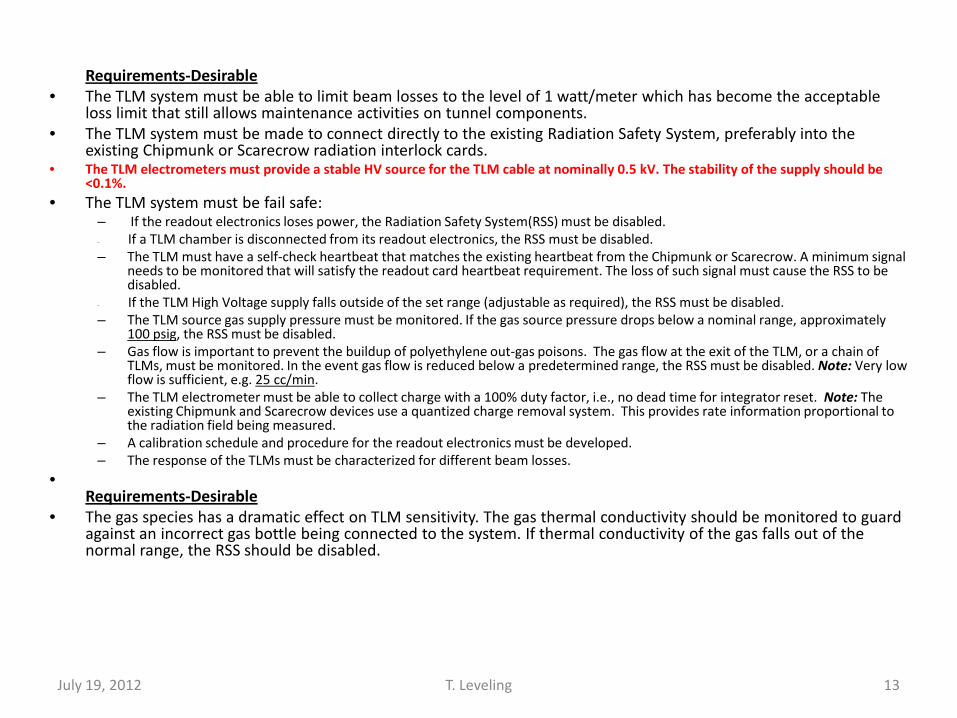
Requirements-Desirable • The TLM system must be able to limit beam losses to the level of 1 watt/meter which has become the acceptable
loss limit that still allows maintenance activities on tunnel components. • The TLM system must be made to connect directly to the existing Radiation Safety System, preferably into the
existing Chipmunk or Scarecrow radiation interlock cards. • The TLM electrometers must provide a stable HV source for the TLM cable at nominally 0.5 kV. The stability of the supply should be
<0.1%. • The TLM system must be fail safe:
– If the readout electronics loses power, the Radiation Safety System(RSS) must be disabled. – If a TLM chamber is disconnected from its readout electronics, the RSS must be disabled. – The TLM must have a self-check heartbeat that matches the existing heartbeat from the Chipmunk or Scarecrow. A minimum signal
needs to be monitored that will satisfy the readout card heartbeat requirement. The loss of such signal must cause the RSS to be disabled.
– If the TLM High Voltage supply falls outside of the set range (adjustable as required), the RSS must be disabled. – The TLM source gas supply pressure must be monitored. If the gas source pressure drops below a nominal range, approximately
100 psig, the RSS must be disabled. – Gas flow is important to prevent the buildup of polyethylene out-gas poisons. The gas flow at the exit of the TLM, or a chain of
TLMs, must be monitored. In the event gas flow is reduced below a predetermined range, the RSS must be disabled. Note: Very low flow is sufficient, e.g. 25 cc/min.
– The TLM electrometer must be able to collect charge with a 100% duty factor, i.e., no dead time for integrator reset. Note: The existing Chipmunk and Scarecrow devices use a quantized charge removal system. This provides rate information proportional to the radiation field being measured.
– A calibration schedule and procedure for the readout electronics must be developed. – The response of the TLMs must be characterized for different beam losses.
• Requirements-Desirable
• The gas species has a dramatic effect on TLM sensitivity. The gas thermal conductivity should be monitored to guard against an incorrect gas bottle being connected to the system. If thermal conductivity of the gas falls out of the normal range, the RSS should be disabled.
13 July 19, 2012 T. Leveling

14
8 GeV TLM response constant TLM baseline energy Energy scalling factor Baseline TLM distance to beam center
3.2 nC/E10 8 GeV 0.8 5.5 feet
Machine/Condition Note Beam power (KW)
Energy (GeV)
Protons per hour
Average intensity
per second
Nominal Shielding
feet
Magnet to ceiling
distance
Shield Category or application
basis
beam loss limit (p/s)
normal loss limit
p/s
% of beam loss
nC/min (per meter
in bold)
Mu2e Service Bldg. 1 4 8 1.13E+16 3.13E+12 10 5.5 skyshine 3.3 watts 2.58E+09 0.082% 50
Mu2e Service Bldg. 1 8 8 2.25E+16 6.25E+12 10 5.5 skyshine 3.3 watts 2.58E+09 0.041% 50
Mu2e Shielding Berm 2 4 8 1.13E+16 3.13E+12 13 5.5 1A 3.26E+10 1.63E+09 0.052% 31
Mu2e Shielding Berm 2 8 8 2.25E+16 6.25E+12 13 5.5 1A 3.26E+10 1.63E+09 0.026% 31
Booster May 2013 5 64 8 1.80E+17 5.00E+13 14 4 2A 2.20E+11 1.10E+10 0.022% 399
Booster 2016 5 80 8 2.25E+17 6.25E+13 14 4 2A 2.20E+11 1.10E+10 0.018% 399
Booster (any pwr) 3 8 14 4 1 W/m NA 3.91E+11 14,175
Main Injector 2 700 120 1.31E+17 3.65E+13 24 5 1A 2.61E+13 1.31E+12 3.582% 265,094
Main Injector 2 2,300 120 4.31E+17 1.20E+14 24 5 1A 2.61E+13 1.31E+12 1.090% 265,094
Main Injector 3 700 120 1.31E+17 3.65E+13 24 5 1 W/m NA 1.82E+11 0.499% 36,960
Main Injector 3 2,300 120 4.31E+17 1.20E+14 24 5 1 W/m NA 1.82E+11 0.152% 36,960
Nova 2 700 120 1.31E+17 3.65E+13 26 3 1A 4.87E+13 2.44E+12 6.675% 1,372,243
LBNE 2 2,300 120 4.31E+17 1.20E+14 26 3 1A 4.87E+13 2.44E+12 2.030% 1,372,243
Nova 4 700 120 1.31E+17 3.65E+13 26 3 10 ppm NA 3.65E+08 0.001% 206
LBNE 4 2,300 120 4.31E+17 1.20E+14 26 3 1 W/m NA 5.21E+07 0.000% 29
Notes: 1 Distributed or concentrated loss limits public exposure to 1 mrem per year 2 Single point loss limits berm surface normal condition dose rate to 0.05 mrem/hr 3 Total charge limit in tunnel beam loss to 1 W/m - distributed among some number of TLMs 4 Limit total beam loss to 1 part in 1E5 5
Single point loss limits berm surface normal condition dose rate to 5 mrem/hr
Not recommended July 19, 2012 T. Leveling
The scaling of TLM response for energy needs to be Checked in a MARS calculation!!!!

Dynamic Range • At 3.2 nC/E10 protons
– Full beam power loss of a single 5E13 pulse at 120 GeV would produce 118 uC
• No intention to measure/detect for this level
– For 1 W/m loss around the MI, a total of 0.6 nC/MI pulse is produced
– Divided among 12 TLMs a total of 0.05 nC/pulse
– A 3.5E12 pulse at 8 GeV would produce about 1 uC
• Arbitrarily, a 1-2 uC/pulse upper limit is probably sufficient
• All anticipated trip levels are well below this per pulse limit
15 July 19, 2012 T. Leveling

Digitizer circuit
• Suppose 5 uC/minute is a reasonable upper control limit
• Rad card input upper limit – 10 kHz (?)
• Then digitizer charge per output pulse
July 19, 2012 T. Leveling 16
pulsepCkHzs
uC /33.810
1605
=∗

Chipmunk digitizer
• For comparison – 0.5 pC/pulse, 2.5 pC/pulse or 5 pC/pulse
(selectable)
July 19, 2012 T. Leveling 17
Low trip level
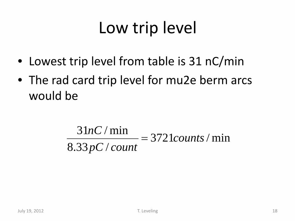
• Lowest trip level from table is 31 nC/min
• The rad card trip level for mu2e berm arcs would be
July 19, 2012 T. Leveling 18
min/3721/33.8min/31 countscountpC
nC=

TLM needs a heartbeat
• Add resistor across TLM to force current
• For a 60 cpm background – Assume 500 volt bias
– 8.33 pC/pulse or 8.33 pA
July 19, 2012 T. Leveling 19
IER /=
R= 60 teraohms

TLM electrometer Form Factor
July 19, 2012 T. Leveling 20

• Panel mounted for installation in relay rack • SHV connector output for TLM bias • BNC connector signal input from TLM • Output signals connect to RSS through Burndy connector
– HV OK? – DC voltage – Digitizer output as TTL – Other?
• 120 volt power cord • Status lights
– HV – Heartbeat reflection
July 19, 2012 T. Leveling 21
Backup slides
22 July 19, 2012 T. Leveling

23 July 19, 2012 T. Leveling

24 July 19, 2012 T. Leveling

25 July 19, 2012 T. Leveling

26
3.1E10 protons 3.35E12 protons
Scope terminated into 1 Mohm
July 19, 2012 T. Leveling
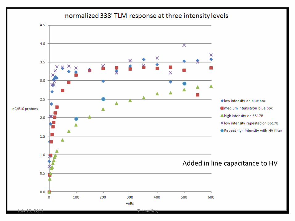
27
Added in line capacitance to HV
July 19, 2012 T. Leveling
28
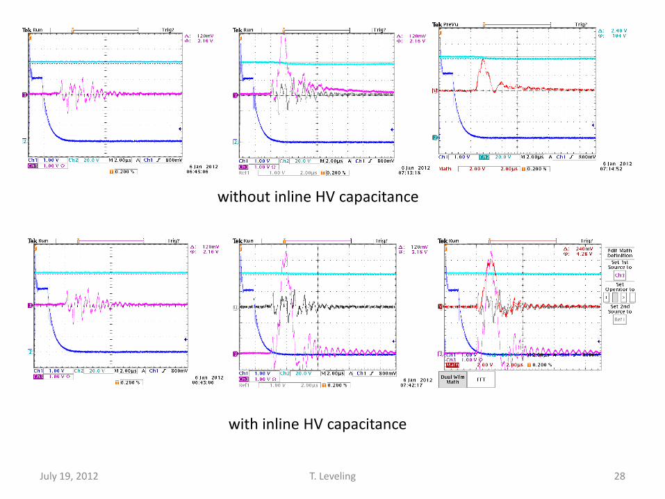
without inline HV capacitance
with inline HV capacitance
July 19, 2012 T. Leveling

29
Three traces: 1- background, 2 – without HV cap, 3 – with HV cap
1
2
3
July 19, 2012 T. Leveling

Compared Scope measurement with 6517B for similar beam loss
• With TLM HV at 100 volts – Scope with no HV filter – 155 nC
– Scope with HV filter – 145 nC
– With 6517B – 660 nC
• Scope technique didn’t work
30 July 19, 2012 T. Leveling
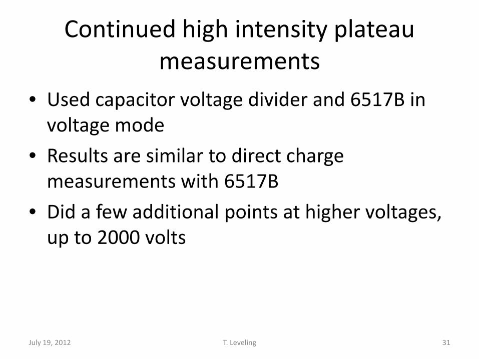
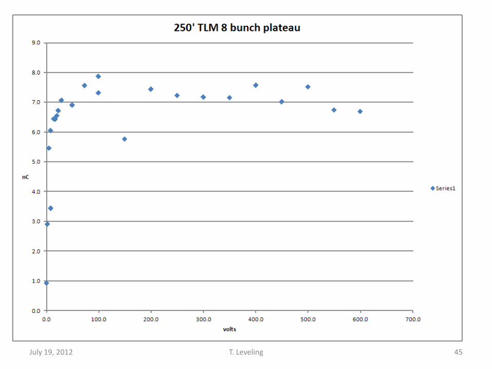
Continued high intensity plateau measurements
• Used capacitor voltage divider and 6517B in voltage mode
• Results are similar to direct charge measurements with 6517B
• Did a few additional points at higher voltages, up to 2000 volts
31 July 19, 2012 T. Leveling

32 July 19, 2012 T. Leveling

TLM use at the intensity Frontier
• Clearly, beam intensity could be high enough to saturate TLMs
• All measurements to date at 8 GeV
• Response of TLM at 120 GeV expected to be:
33
(E120/E8)0.8 X 3.2nC/E10 protons = 28nC/E10 protons
July 19, 2012 T. Leveling

34
Saw this in September while comparing blue box response to BLM chassis
July 19, 2012 T. Leveling

35
Ch1 – 125’ Ch2 – 250’ Ch4 – 338’
July 19, 2012 T. Leveling

36
TLM response varies with different loss mechanisms
Use the most conservative condition to establish safety system trip
July 19, 2012 T. Leveling

37 July 19, 2012 T. Leveling

38 July 19, 2012 T. Leveling

39 July 19, 2012 T. Leveling

40 July 19, 2012 T. Leveling

41 July 19, 2012 T. Leveling

42 July 19, 2012 T. Leveling

43
4E11 protons into A2B7
July 19, 2012 T. Leveling

8E10 protons into A2B7
July 19, 2012 44 T. Leveling
45 July 19, 2012 T. Leveling

46 July 19, 2012 T. Leveling

47 July 19, 2012 T. Leveling
Next steps
• Finish charge collection time measurement – Probably requires max intensity to get a signal
• Do high intensity plateaus for 250’ and 338’ TLMs – Use 6517B for one and blue box for the other
– Then switch
– Look for roll off in blue box response
48 July 19, 2012 T. Leveling

TLM electronics development resources • Management
– EE? – ES&H?
• M&S – Probably need a budget for this
• First, need an estimate? • Funded by users?
– ES&H – Mu2e – Pixie – Others
• Resources – ES&H files
• Labor – Marv – Others?
49 July 19, 2012 T. Leveling

Since the last meeting
Current BLM chassis contains: 6 decade log rate cards 0.014 RADS 0.14 RADS 1.4 RADS 14 RADS
50 July 19, 2012 T. Leveling

Scope pictures
125 foot response
250 response
50 Booster bunches Partial scraping loss on elam
51 July 19, 2012 T. Leveling
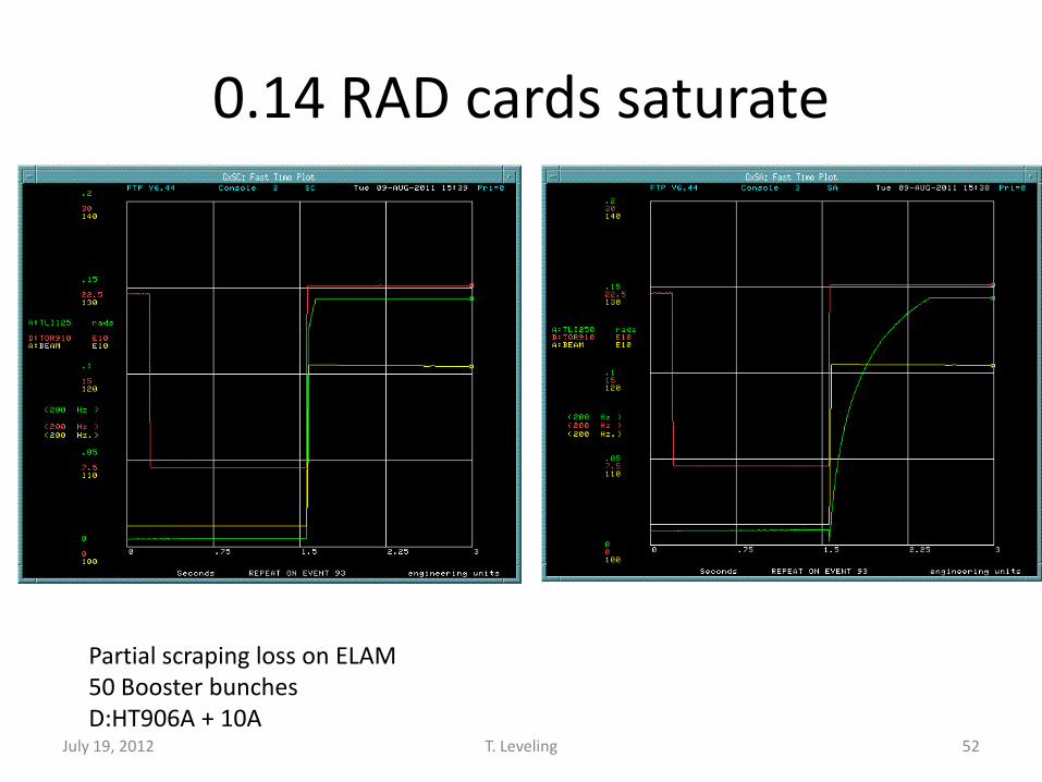
0.14 RAD cards saturate
Partial scraping loss on ELAM 50 Booster bunches D:HT906A + 10A
52 July 19, 2012 T. Leveling

Repeated 2000 Pbar SA measurement
Counts per mA lost Expected these curves to be consistent Demonstrates that scraping loss is unreliable technique to establish response 53 July 19, 2012 T. Leveling

Single resets do not clear BLM cards in all cases
54 July 19, 2012 T. Leveling

Clear on 00 event and 93 event
Used reset at beginning of transfer timeline to clear integrator
55 July 19, 2012 T. Leveling

TLMs samples on 93 reverse proton tuneup event
Transfers over 24 h period TLM response coincident with chipmunk response outside of shielding
56 July 19, 2012 T. Leveling

Small negative currents occur
e.g. when beam goes away
Chipmunks have Cs-137
source to drive
current
57 July 19, 2012 T. Leveling

Some minutes of operation
58 July 19, 2012 T. Leveling

Script has been written to ramp elam simplifies beam loss studies
Script by DVM
59 July 19, 2012 T. Leveling

TLM response correlated with beam power on target by timeline variation
60 July 19, 2012 T. Leveling
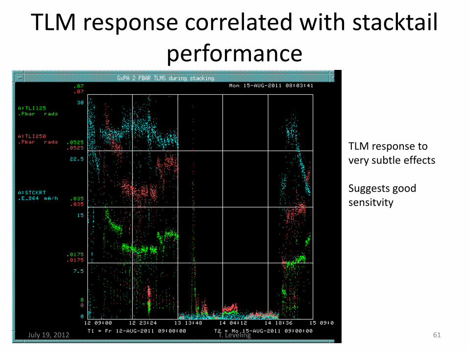
TLM response correlated with stacktail performance
TLM response to very subtle effects Suggests good sensitvity
61 July 19, 2012 T. Leveling

A series of measurements have been variable beam loss
35 Booster buckets - 15.7E10 protons Others in 5 bucket increments from 5 to 50
62 July 19, 2012 T. Leveling

Recorded response of 5 chipmunks
63 July 19, 2012 T. Leveling

Chipmunk response is linear with number of protons lost
An expected result
64 July 19, 2012 T. Leveling

TLMs also have linear response!
A required result
NOTE! 125 foot response exceeds 250 foot
response
250’ TLM response = 70%*125’response 65 July 19, 2012 T. Leveling

TLM response as a function of length
• Need another TLM installed to determine this!
66 July 19, 2012 T. Leveling

During stacking operations 250’ cable response
exceeds 125’ response during normal stacking
operations
A reverse proton cycle mixed in with
stacking cycles
Could be losses in the second half of 250’ TLM not seen by 125’ TLM
67 July 19, 2012 T. Leveling
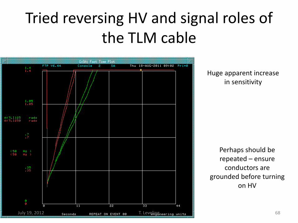
Tried reversing HV and signal roles of the TLM cable
Huge apparent increase in sensitivity
Perhaps should be repeated – ensure
conductors are grounded before turning
on HV
68 July 19, 2012 T. Leveling

Blue box is in service connected to 125’ TLM
69 July 19, 2012 T. Leveling

Blue box is in service connected to 125’ TLM
70 July 19, 2012 T. Leveling

Blue box is in service connected to 125’ TLM
5 pC/count Follows BLM card response on 250’ TLM
71 July 19, 2012 T. Leveling

Next steps (1 of 3)
• Install VME scalar for higher counting rate from blue box (1 kHz) – MUX good for 70 Hz – VME scalar good for 15 kHz
• Repeat series of measurements with blue box and BLM chassis two ways – Blue box/125’ & BLM chassis/250’ – Blue box/250’ & BLM chassis/125’ – Determine dynamic range requirement for digitizer
circuit for TLM application
72 July 19, 2012 T. Leveling

Next steps (2 of 3)
• Install third TLM of different length 103 m (338’) – Determine TLM response as function of length
• Can’t do this with just 2 cables
– Repeat measurements (5 Booster bunch increments)
• Determine how AD instrumentation can make additional blue boxes – In collaboration with ES&H Section
– Would help to speed up development of this resource
73 July 19, 2012 T. Leveling

Next steps (3 of 3)
• Distributed loss study – e.g., Scrape at ELAM with Accumulator bend bus
off (October 2011?)
• Determine blue box trip levels for 14 TLM cables required for mu2e – Needed to finalize radiation safety plan for mu2e
74 July 19, 2012 T. Leveling