july, 2015 - jecrc university · single and three phase fully controlled converter fed series and...
TRANSCRIPT

School of Engineering
Course Structure and Syllabi
M. Tech.
(Power Electronics & Electric Drives)
Academic Programme
July, 2015

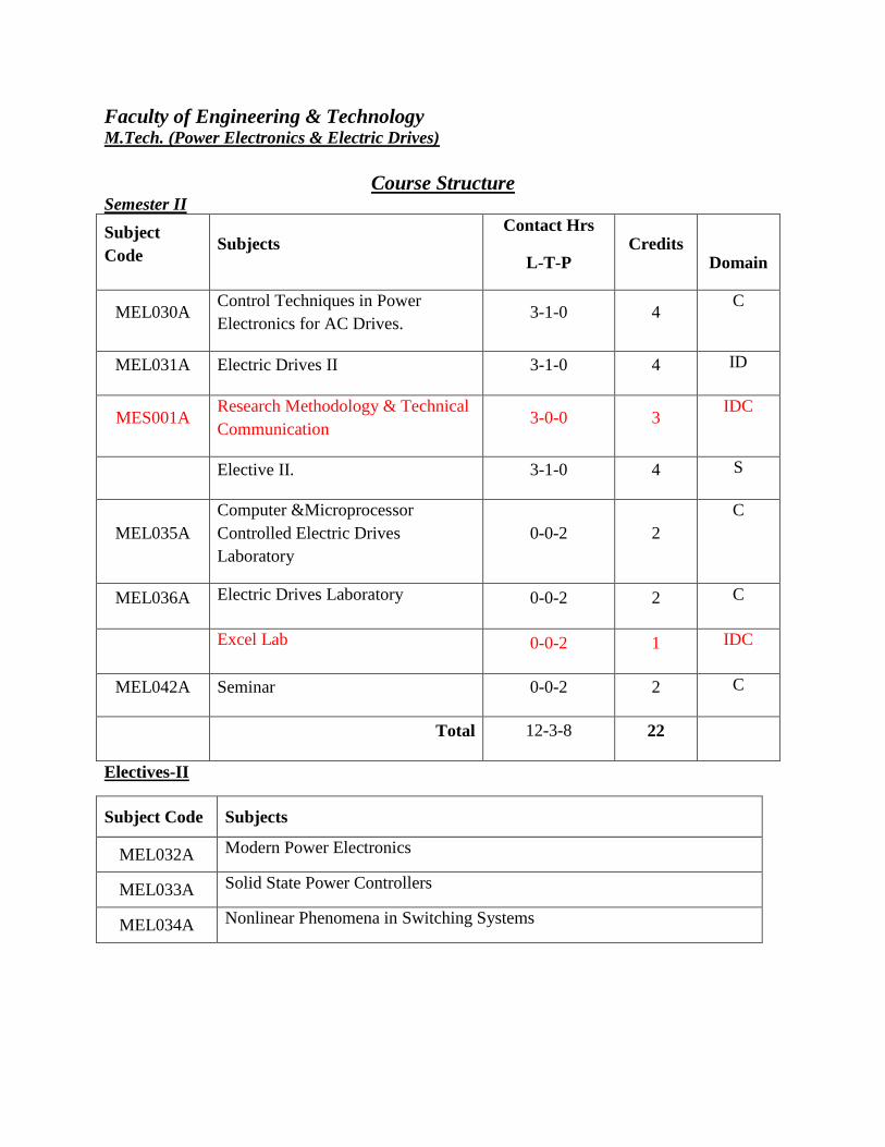
Faculty of Engineering & Technology M.Tech. (Power Electronics & Electric Drives)
Course Structure Semester I
Subject
Code Subjects
Contact Hrs
L-T-P Credits
Domain
MEL022A Power Electronic Converters 3-1-0 4 C
MEL023A Electric Drives I 3-1-0 4 C
MEL024A Neural Network & Fuzzy Systems 3-1-0 4 S
Elective I 3-1-0 4 S
MEL028A Power Electronic Converters
Laboratory 0-0-2 2
C
MEL029A Neural and Fuzzy Laboratory 0-0-2 2 C
MEL0410 Seminar 0-0-2 2 C
Total 12-4-6 22
Electives-I
Subject Code Subjects
MEL025A HVDC Transmission
MEL026A Digital Signal Processing
MEL027A Digital Controllers in Power Electronics Applications
Faculty of Engineering & Technology M.Tech. (Power Electronics & Electric Drives)
Course Structure Semester II
Subject
Code Subjects
Contact Hrs
L-T-P Credits
Domain
MEL030A Control Techniques in Power
Electronics for AC Drives. 3-1-0 4
C
MEL031A Electric Drives II 3-1-0 4 ID
MES001A Research Methodology & Technical
Communication 3-0-0 3
IDC
Elective II. 3-1-0 4 S
MEL035A
Computer &Microprocessor
Controlled Electric Drives
Laboratory
0-0-2 2
C
MEL036A Electric Drives Laboratory 0-0-2 2 C
Excel Lab 0-0-2 1 IDC
MEL042A Seminar 0-0-2 2 C
Total 12-3-8 22
Electives-II
Subject Code Subjects
MEL032A Modern Power Electronics
MEL033A Solid State Power Controllers
MEL034A Nonlinear Phenomena in Switching Systems
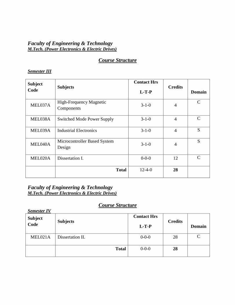
Faculty of Engineering & Technology M.Tech. (Power Electronics & Electric Drives)
Course Structure
Semester III
Subject
Code Subjects
Contact Hrs
L-T-P Credits
Domain
MEL037A High-Frequency Magnetic
Components 3-1-0 4
C
MEL038A Switched Mode Power Supply 3-1-0 4 C
MEL039A Industrial Electronics 3-1-0 4 S
MEL040A Microcontroller Based System
Design 3-1-0 4
S
MEL020A Dissertation I. 0-0-0 12 C
Total 12-4-0 28
Faculty of Engineering & Technology M.Tech. (Power Electronics & Electric Drives)
Course Structure Semester IV
Subject
Code Subjects
Contact Hrs
L-T-P Credits
Domain
MEL021A Dissertation II. 0-0-0 28 C
Total 0-0-0 28

Faculty of Engineering & Technology M.Tech in Electric Drives & Power Electronics (Electrical Engineering) – Semester I
Contact Hrs per week (L-T-P) : 3-1-0
Course Outlines
MEL022A- Power Electronic Converters
OBJECTIVE:
1. To develop students with an understanding of the switching behaviour and design of
power electronics circuits such as PWM Inverters, RPI.
2. To introduce to students the principles and operation Multi level Inverters.
Unit1: PWM INVERTERS Principle of operation – performance parameters – single phase
bridge inverter – evaluation of output voltage and current with resistive, inductive and capacitive
loads – Voltage control of single phase inverters – single PWM – Multiple PWM – sinusoidal
PWM – modified PWM – phase displacement Control.
Unit2: THREE PHASE INVERTERS – analysis of 180 degree condition for output voltage
And current with resistive, inductive loads – analysis of 120 degree Conduction – voltage control
of three phase inverters – sinusoidal PWM – Third Harmonic PWM – 60 degree PWM – space
vector modulation. Comparison of PWM techniques – harmonic reductions – Current Source
Inverter – variable DC link inverter – buck and boost inverter – inverter circuit design –
advantage applications –numerical problems.
Unit 3: RESONANT PULSE INVERTERS Resonant pulse inverters – series resonant inverters
– series resonant inverters with unidirectional switches – series resonant inverters with
bidirectional Switches – analysis of half bridge resonant inverter - evaluation of currents and
Voltages of a simple resonant inverter – analysis of half bridge and full bridge resonant inverter
with bidirectional switches.
Unit4: RESONANT CONVERTERS: Resonant converters – Zero current switching resonant
converters Ltype ZCS resonant converter – M type ZCS resonant converter – zero voltage
Switching resonant converters – comparison between ZCS and ZVS resonant Converters – Two
quadrant ZVS resonant converters – resonant de-link Inverters – evaluation of L and C for a zero
current switching inverter – Numerical problems.
Unit5: MULTI LEVEL INVERTERS Introduction, Multilevel Concept, Types of Multilevel
Inverters- Diode-Clamped Multi level Inverter, Principle of Operation, Features of Diode-
Clamped Inverter, and Improved Diode-Clamped Inverter.
OUTCOMES:
1. Ability to identify, formulate and solve engineering problems will be developed.
2. Ability to use the techniques, skills and modern engineering tools necessary for engineering
practice will be developed.
3. Ability to work on various Inverters such as PWI, RPI.
TEXTBOOKS
1. Power Electronics-Md. H. Rashid –Pearson Education Third Edition- First Indian
Reprint- 2008
REFERENCE BOOKS
1. Power Electronics- Ned Mohan, Tore M. Undelan and William P. Robbins –John Wiley
& Sons -2nd Edition.
Faculty of Engineering & Technology M.Tech in Electric Drives & Power Electronics (Electrical Engineering) – Semester I
Contact Hrs per week (L-T-P) :3-1-0
Course Outlines
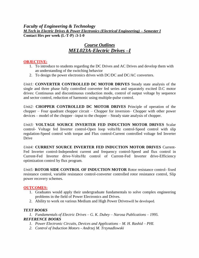
MEL023A-Electric Drives –I
OBJECTIVE:
1. To introduce to students regarding the DC Drives and AC Drives and develop them with
an understanding of the switching behavior
2. To design the power electronics drives with DC/DC and DC/AC converters.
Unit1: CONVERTER CONTROLLED DC MOTOR DRIVES Steady state analysis of the
single and three phase fully controlled converter fed series and separately excited D.C motor
drives: Continuous and discontinuous conduction mode, control of output voltage by sequence
and sector control, reduction of harmonic using multiple-pulse control.
Unit2: CHOPPER CONTROLLED DC MOTOR DRIVES Principle of operation of the
chopper – Four quadrant chopper circuit – Chopper for inversion– Chopper with other power
devices – model of the chopper –input to the chopper – Steady state analysis of chopper.
Unit3: VOLTAGE SOURCE INVERTER FED INDUCTION MOTOR DRIVES Scalar
control- Voltage fed Inverter control-Open loop volts/Hz control-Speed control with slip
regulation-Speed control with torque and Flux control-Current controlled voltage fed Inverter
Drive
Unit4: CURRENT SOURCE INVERTER FED INDUCTION MOTOR DRIVES Current-
Fed Inverter control-Independent current and frequency control-Speed and flux control in
Current-Fed Inverter drive-Volts/Hz control of Current-Fed Inverter drive-Efficiency
optimization control by flux program.
Unit5: ROTOR SIDE CONTROL OF INDUCTION MOTOR Rotor resistance control- fixed
resistance control, variable resistance control-converter controlled rotor resistance control, Slip
power recovery schemes.
OUTCOMES:
1. Graduates would apply their undergraduate fundamentals to solve complex engineering
problems in the field of Power Electronics and Drives.
2. Ability to work on various Medium and High Power Driveswill be developed.
TEXT BOOKS
1. Fundamentals of Electric Drives – G. K. Dubey – Narosa Publications – 1995.
REFERENCE BOOKS
1. Power Electronic Circuits, Devices and Applications – M. H. Rashid – PHI.
2. Control of Induction Motors - Andrzej M. Trzynadlowski
Faculty of Engineering & Technology
M.Tech in Electric Drives & Power Electronics (Electrical Engineering) – Semester I
Contact Hrs per week (L-T-P) : 3-1-0
Course Outlines
MEL024A-Neural Network & Fuzzy Systems
OBJECTIVE: 1. Biological motivation to design intelligent systems and control.
2. The study of control-theoretic foundations such as stability and robustness in the frame
work of intelligent control.
3. Computer simulation of intelligent control systems to evaluate the performance.
Unit 1: Introduction to Neural Networks Introduction, Humans and Computers, Organization
of the Brain, Biological Neuron, Biological and Artificial Neuron Models, Hodgkin-Huxley
Neuron Model, Integrate-and-Fire Neuron Model, Spiking Neuron Model, Characteristics of
ANN, McCulloch-Pitts Model, Historical Developments.
Unit 2: Feed Forward Neural Networks Introduction, Perceptron Models: Discrete, Continuous
and Multi-Category, Training Algorithms: Discrete and Continuous Perceptron Networks,
Perceptron Convergence theorem, Limitations of the Perceptron Model, Applications.
Unit 3: Associative Memories Paradigms of Associative Memory, Pattern Mathematics,
Hebbian Learning, General Concepts of Associative Memory (Associative Matrix, Association
Rules, Hamming Distance, The Linear Associate, Matrix Memories.
Unit 4: Self-Organizing Maps (SOM) and Adaptive Resonance Theory (ART) Introduction,
Competitive Learning, Vector Quantization, Self-Organized Learning Networks, Kohonen
Networks, Training Algorithms, Linear Vector Quantization, Stability- Plasticity Dilemma, Feed
forward competition, Feedback Competition.
Unit 5: Applications Neural network applications: Process identification, Fraction
Approximation, Control and Process Monitoring, Fault diagnosis and Load forecasting. Fuzzy
logic control and Fuzzy classification.
OUTCOMES:
1. The students will be able to solve the simple practical problems in an efficient manner
using either neural network or fuzzy system.
TEXT BOOKS
1. Neural Netwroks, Fuzylogic ,Gnenetic algorithms: synthesis and applications by
Rajasekharan and Rai- PHI Publication.
REFERENCE BOOKS
1. Neural Netwroks – James A Freeman and Davis Skapura, Pearson, 2002
2. Neural Netwroks – Simon Hykins, Pearson Education.
3. Neural Engineering by C. Eliasmith and CH. Anderson, PHI
4. Neural Netwroks and Fuzzy Logic System by BrokKosko, PHI Publications
Faculty of Engineering & Technology M.Tech. in Power Electronics & Electric Drives (Electrical Engineering)-Semester I
Contact Hrs per week (L-T-P): 3-1-0
Course Outlines
MEL025A-HVDC Transmission
OBJECTIVE:
1. To provide an in-depth understanding of the different aspects of Extra High Voltage A.C.
and D.C. Transmission system design and Analysis.
Unit 1: Introduction to HVDC- General Consideration, Power Handling Capabilities of HVDC
Lines Basic Conversion principles, static converter configuration.
Unit 2: Static Power Converters- 3-pulse, 6-pulse, and 12-pulse converters, converter station
and Terminal equipment, commutation process, Rectifier and inverter operation, equivalent
circuit for converter – special features of converter transformers. Harmonics in HVDC Systems,
Harmonic elimination, AC and DC filters.
Unit 3: Control of HVDC Converters AND Systems- Constant current, constant extinction
angle and constant ignition angle control Individual phase control and equidistant firing angle
control DC power flow control. Interaction between HV AC and DC systems – Voltage
interaction Harmonic instability problems and DC power modulation.
Unit 4: MTDC Systems &Over Voltages- Series parallel and series parallel systems their
operation and control. Over voltages due to disturbances on DC side, over voltages due to DC
and AC side line faults.
Unit 5: Converter Faults & Protection- Converter faults, over current protection – valve group,
and DC line protection over voltage protection of converters, surge arresters.
OUTCOMES:
1. The students would be able to appreciate the advantages (and disadvantages) of using
HVDC for bulk power transmission, benefits and limitations associated with HVDC
technology and their application areas.
2. At the end student will be able to design commercial transmission systems.
Text Books:
1. E.W. Kimbark: Direct current Transmission, Wiely Inter Science – New York.
Reference Books:
1. KR Padiyar : High Voltage Direct current Transmission WielyEsatern Ltd New Delhi –
1992.
2. E. Uhlman : Power Transmission by Direct Current , Springer Verlag, Berlin Helberg-
1985.
Faculty of Engineering & Technology M.Tech in Electric Drives & Power Electronics (Electrical Engineering)-Semester I
Contact Hrs per week (L-T-P) : 3-1-0
Course Outlines
MEL026A-Digital Signal Processing
OBJECTIVE:
1. To understand the basic function of digital signal processing and to explore the features
of digital filters to the students.
2. To understand the discrete Fourier transform and fast Fourier transform for signal
processing.
Unit1: Introduction to Signal Processing: Review of Laplace transform, Z transform, Fourier
transform. Discrete Fourier transform, Fast Fourier transform, Algorithms and complexity,
Unit 2: Classification of filter design- Design of IIR filters, bilinear transformation technique,
Impulse invariance method – Step invariance method FIR filter design, Fourier series method,
Window function technique, Finite Word Length Effects
Unit 3: Digital Filter: Definition and anatomy of a digital filter, Frequency domain description of
signals and systems, typical application of digital filters, Replacing analogue filters with digital
filters, Filter categories: recursive and non-recursive.
Unit4: Digital Filter Structures: The direct form I and II structures, Cascade combination of
second order sections, Parallel combination of second order sections, Linear- phase FIR filter
structures, Frequency sampling structure for the FIR filter.
Unit 5: Effect of Word Length: Round off error, Truncation error, Quantization error, Limit
cycle Introduction to DSP Hardware: Application of DSP in control system and instrumentation.
OUTCOMES: 1. The students will be able to usediscrete Fourier transform and fast Fourier transform for
signal processing application.
2. They will be able to understand the concept of digital filter.
TEXT BOOKS
1. J. C. Proakis, and D. G. Maniolakis, Digital Signal Processing: Principles, Algorithms
and Applications, Prentice Hall.
REFERENCE BOOKS
1. Oppenheim, and R. W. Shaffer, Discrete Time Signal Processing, Prentice Hall, 1992.
2. J. Johnson, Digital Signal Processing, Prentice Hall.
3. B. VenkataRamani, and M. Bhaskar, Digital Signal Processors, New Delhi: Tata
McGraw Hill

Faculty of Engineering & Technology M.Tech in Electric Drives & Power Electronics (Electrical Engineering)-Semester I
Contact Hrs per week (L-T-P) : 3-1-0
Course Outlines
MEL027A-Digital Controllers in Power Electronics Applications OBJECTIVE:
1. To introduce the Digital Controllers in the Field of Power Electronics.
2. To understand the working of Multiplexer & use of HDL Programming.
Unit 1: Introduction to the C2xx DSP core and code generation, The components of the C2xx
DSP core, Mapping external devices to the C2xx core, peripherals and Peripheral Interface,
System configuration registers, Memory, Types of Physical Memory , memory Addressing
Modes , Assembly Programming using C2xx DSP, Instruction Set, Software Tools.
Unit 2: Pin Multiplexing (MUX) and General Purpose I/O Overview, Multiplexing and General
Purpose I/O Control Registers. Introduction to Interrupts, Interrupt Hierarchy, Interrupt Control
Registers, Initializing and Servicing Interrupts in Software.
Unit 3: ADC Overview , Operation of the ADC in the DSP , Overview of the Event manager
(EV) , Event Manager Interrupts , General Purpose (GP) Timers , Compare Units, Capture Units
And Quadrature Enclosed Pulse (QEP) Circuitry, General Event Manager Information.
Unit 4: Introduction to Field Programmable Gate Arrays – CPLD Vs FPGA – Types of FPGA,
Xilinx XC3000 series, Configurable logic Blocks (CLB), Input/output Block Programmable
Interconnect Point (PIP) – Xilinx 4000 series.
Unit 5: HDL programming –overview of Spartan 3E and Virtex II pro FPGA boards- case study.
Controlled Rectifier, Switched Mode Power Converters, PWM Inverters, DC motor control,
Induction Motor Control.
OUTCOMES: 1. Students will be able to understand use of Digital Controllers in the Field of Power
Electronics.
2. Students will understand the working of Multiplexer & use of HDL Programming.
TEXT BOOKS
1. Hamid.A.Toliyat and Steven G.Campbell “ DSP Based Electro Mechanical Motion
Control “ CRC Press New York , 2004
REFERENCE BOOKS
1. XC 3000 series datasheets ( version 3.1). Xilinx,Inc.,USA, 1998
2. XC 4000 series datasheets ( version 1.6). Xilinx,Inc.,USA, 1999
3. Wayne Wolf,” FPGA based system design “, Prentice hall, 2004.

Faculty of Engineering & Technology
M.Tech in Electric Drives & Power Electronics (Electrical Engineering) – Semester I
Contact Hrs per week (L-T-P) : 0-0-2
Course Outlines
MEL028A-Power Electronic Converters Laboratory
OBJECTIVE:
1. TO enhance the practical knowledge of students.
2. To explain the use of Power Electronic Converters.
List of Experiments
1. Speed Measurement and closed loop control using PMDC motor.
2. Thyristorised drive for PMDC Motor with speed measurement and closed Loop control.
3. IGBT used single 4 quadrant chopper drive for PMDC motor with speed measurement
and closed loop control.
4. Thyristorised drive for 1Hp DC motor with closed loop control.
5. 3-Phase input, thyristorised drive, 3 Hp DC motor with closed loop
6. 3-Phase input IGBT, 4 quadrant chopper drive for DC motor with closed Loop control
equipment.
7. Cycloconverter based AC Induction motor control equipment.
8. Speed control of 3 phase wound rotor Induction motor.
9. Single-phase fully controlled converter with inductive load.
10. Single phase half wave controlled converter with inductive load.
11. DC to DC converters of various configurations using SCRs, IGBTs, power transistors and
power MOSFETs.
12. DC to AC converters of various configurations using SCRs, IGBTs, power transistors and
power MOSFETs.
13. AC to AC converters of various configurations using SCRs, IGBTs, power transistors and
power MOSFETs.
14. Practical implementation of control techniques for voltage control, speed control and
harmonic minimization.
15. Practical converter design considerations- Snubber design, gate and base drive circuits.
OUTCOMES: 1. The students will be able to understand the working of different types of Power electronic
converters.

Faculty of Engineering & Technology M.Tech in Electric Drives & Power Electronics (Electrical Engineering) – Semester I
Contact Hrs per week (L-T-P) : 0-0-2
Course Outlines
MEL029A-Neural and Fuzzy Laboratory
OBJECTIVE: 1. To explain the use of neural and fuzzy logic in Engineering application.
2. To design speed controller for different electric motors.
List of Experiments
1. Programming on Supervised Learning Using NN Matlab Toolbox.
2. Define one sample: inputs and outputs.
3. Create Network to Define and custom network.
4. Programming to define topology and transfer function.
5. Programming to configure network.
6. Programming to Train net and calculate neuron output.
7. Design a Hebb net as a gate traffic controller across the road to control the accidents
occurring on the roads regularly. The gate across the road will come down across when
the traffic light is red & pedestrian light is green. Also plot classification line and
input/output target vectors.
8. Consider the surface described by z= sin(x) cos(y) defined on a square -3≤x≤ 3, -3≤y≤
3Plot the surface z as function of x & y and design a neural network which will fit the
data. Hint: Use 25, 25 numbers of neurons in first layer, show 50, 0.05 learning rate, 1e-3
goal and 300 epochs before training network.
9. To implement fuzzy controller for temperature control of an oven.
10. To implement fuzzy controller for water level control of a single and two tank coupled
system
11. To implement fuzzy controller for speed control of DC Motor.
12. To implement fuzzy controller for speed control of Stepper Motor.
13. To implement fuzzy controller on second order system
14. To implement fuzzy controller on Third order system
15. To implement fuzzy controller for measuring pressure of hydraulic system
16. To implement fuzzy controller for measuring pressure of pneumatic system
17. To implement fuzzy controller for vector control of induction motor.
OUTCOMES: 1. The students will be able to understand the different types of fuzzy controllers for speed
control.
2. Students will be able to design fuzzy controller for second and third order systems.

Faculty of Engineering & Technology M.Tech in Electric Drives & Power Electronics (Electrical Engineering) – Semester II
Contact Hrs per week (L-T-P) : 3-1-0
Course Outlines
MEL030A-Control Techniques in Power Electronics for AC Drives
OBJECTIVE: 1. To equip the students with the knowledge of average modeling of converters.
2. To know about digital control techniques of converters and different type of power
supplies for different applications.
Unit1: AC Voltage Controllers: Principle of On-Off Control, Principle of Phase control, Single
Phase Bi-directional Controllers with Resistive Loads, Single Phase Controllers with Inductive
Loads, Three Phase full wave AC controllers, AC Voltage Controller with PWM Control.
Unit2: Cycloconverter: Basic principle of operation, single phase to single phase, three-phase to
three phase and three phase to single phase Cycloconverter. Output equation; Control circuit.
Unit3: DC Power Supplies: Switched Mode DC Power Supplies, fly back converter, forward
converter, half and full bridge converter, resonant DC power supplies, bi-directional power
supplies.
Unit4: AC Power Supplies: Switched mode power supplies and its application, Resonant AC
power supplies, bidirectional AC power supplies: working principle and its application.
Unit5: Multistage converter, process of conversion. Control Circuits: working of control circuit.
Types of control: Voltage Mode Control, Current Mode Control.
OUTCOMES: 1. The students will be able to understand the modeling of converters.
2. The students will understand digital control techniques of converters and different type of
power supplies for different applications.
Text Books: 1. M.H Rashid:Power Electronics, circuits devices and applications, PHI,1988.
Reference Books: 1. P.C. Sen:Power electronics Tata McGraw-Hill 1987
2. CW Lander:Power electronics,2nd edition, McGrawHill 1987
3. P.S Bimbhra:Power electronics, 2nd Ed. Khanna Publishers,1987
4. M.D.Singh and K.B. Khanchandani:Power electronics, TMH,1998
5. V Subrahmanyam:Power electronics, New Age Inc.Publishers,New Delhi,1996

Faculty of Engineering & Technology
M.Tech in Electric Drives & Power Electronics (Electrical Engineering) – Semester II
Contact Hrs per week (L-T-P) :3-1-0
Course Outlines
MEL031A-Electric Drives-II
OBJECTIVE: 1. To understand the speed control of advanced electrical drives.
2. To show the different type of torque characteristic of different type of electrical motors.
Unit 1: VECTOR CONTROL OF INDUCTION MOTOR: Principles of vector control,
Direct vector control, derivation of indirect vector control, implementation – block diagram;
estimation of flux, flux weakening operation.
Unit 2: SENSORLESS VECTOR CONTROL OF INDUCTION MOTOR: Slip and Speed
Estimation at Low performance, Rotor Angle and Flux‐linkage Estimation at high performance
‐rotor Speed Estimation Scheme.
Unit3: CONTROL OF SYNCHRONOUS MOTOR DRIVES: Synchronous motor and its
characteristics- Control strategies-Constant torque angle control power factor control, constant
flux control, flux weakening operation.
Unit4: CONTROL OF SWITCHED RELUCTANCE MOTOR DRIVES:SRM Structure-
Stator Excitation-techniques of sensor less operation-convertor topologies- SRM Waveforms-
SRM drive design factors-Torque controlled SRM-Torque Ripple.
Unit5: CONTROL OF BLDC MOTOR DRIVES: principle of operation of BLDC Machine,
Sensing and logic switching scheme, BLDM as Variable Speed Synchronous motor-methods of
reducing Torque pulsations -Three-phase full wave Brushless dc motor.
OUTCOMES: 1. The students will be able to control the speed of different type of advance electrical
machine by the use of various converters available in modern era.
TEXT BOOKS
1. Electric Motor Drives Modeling, Analysis & control -R. Krishnan- Pearson Education
REFERENCE BOOKS
1. Sensorless Vector Direct Torque control –Peter Vas, Oxford University Press
2 Modern Power Electronics and AC Drives –B. K. Bose-Pearson Publications-
3 Power Electronics control of AC motors – MD Murphy & FG Turn Bull Pergman Press
-1st edition-1998
4 Fundamentals of Electrical Drives – G.K. Dubey – Narosa Publications -1995
5 Power Semiconductor drives- G.K. Dubey-Prentice hall

Faculty of Engineering & Technology
M.Tech in Electric Drives & Power Electronics (Electrical Engineering) – Semester II
Contact Hrs per week (L-T-P) :3-1-0
Course Outlines
MES001A-Research Methodology & Technical Communication
OBJECTIVE:
1. To enhance the ability of writing and presentation of research work.
Unit 1: Research: Meaning & Purpose, Review of literature, Problem definition/Formulation of
research problem, Research proposal, Variables, Hypothesis, types, construction of hypothesis
Unit 2: Classification of research: Quantitative research: Descriptive Research, Experimental
Research Qualitative research: Observational studies, Historical research, Focus group
discussion, Case study method,
Unit 3: Sources of data collection: Primary and Secondary Data Collection, Sample and
Sampling technology, Non-probability and Probability Sampling
Unit 4: Tools for data collection: Tests, Interview, Observation, Questionnaire/ Schedule,
Characteristics of a good test, Statistics: Descriptive and Inferential Statistics.Data Analysis,
Report Writing, Results and References,
Unit 5: Thesis Writing and Journal Publications: Writing thesis, Writing journal and
conference papers, IEEE and Harvard style of referencing, Effective presentation, Copyrights,
and Avoid plagiarism.
OUTCOMES:
1. The student will be able to write and present their research work efficiently.
Text Books: 1. Borth, Wayne C, et.Al., The Craft of Research: Chicago Guides to Writing Edition and
Publishing.
Reference Books: 1. Meyer, P.L., Introduction to Probability & Statistical, Applications: Oxford, IBH.
2. Hogg, R.V. & Craig, A.T., Introduction to Mathematical Statistics, MacMillan.
3. Goon, A.M., Gupta, M.K. &Dasgupta, Fundamentals of Statistics, Vol.I: World Press.
4. Gupta, S.C. &Kapoor, V.K., Fundamentals of Mathematical Statistics, Sultan Chand &
Sons.
Electives-II
Faculty of Engineering & Technology M.Tech in Electric Drives & Power Electronics (Electrical Engineering) – Semester II
Contact Hrs per week (L-T-P) : 3-1-0
Course Outlines
MEL032A-Modern Power Electronics
OBJECTIVE: 1. To understand the working of resonant inverters and resonant converter.
2. To explore various multilevel inverter to the students.
Unit 1: Modern power semiconductor devices Modern power semiconductor devices- MOS
Turn Off Thyristor (MTO) – Emitter Turn Off Thyristor (ETO) – Integrated Gate – Commutated
thyristor (IGCTs) – MOS – controlled thyristors (MCTs) – Static induction Thyristors (SITHs) –
Power integrated circuits (PICs) – Symbol, structure and equivalent circuit- comparison of their
features.
Unit 2: Resonant pulse inverters Resonant pulse inverters – series resonant inverters- series
resonant inverters with unidirectional switches – series resonant inverters with bidirectional
switches- analysis of half bride resonant inverter- evaluation of currents and Voltages of a simple
resonant inverter.
Unit 3: Resonant Converters Resonant converters- zero current switching resonant converters –
L type ZCS resonant converter- M type ZCS resonant converter – zero voltage Switching
resonant converters – comparison between ZCS and ZVS resonant converters.
Unit 4: Multilevel Inverters Multilevel concept- Classification of multilevel inverters Diode
clamped Multilevel inverter- Principle of operation – main features- improved diode clamped
inverter – principle of operation – Flying capacitors multilevel inverter – principle of operation,
main features.
Unit 5: Power conditioners and Uninterruptible Power Supplies Introduction- power line
disturbances – power conditioners- uninterruptible power supplies applications.
OUTCOMES: 1. The working and classification of different resonant converter and resonant inverter is
discussed.
2. Power conditioners and uninterruptible power supplies is also discussed. TEXT BOOKS:
1. Power Electronics: Mohammed H.Rashid-Pearson Education- Third Edition –first Indian
reprint-2004
REFERENCE BOOKS
1. Power Electronics – Ned Mohan, Tore M.Undeland and William P.Robbind – John wiley& Sons
– Second Edition.
2. Power Electronics , P.S Bimbhra, KhannaPublishers, Delhi, Sixth Edition
Faculty of Engineering & Technology
M.Tech in Electric Drives & Power Electronics (Electrical Engineering)-Semester II
Contact Hrs per week (L-T-P) : 3-1-0
Course Outlines
MEL033A-Solid State Power Controllers OBJECTIVE:
1. To understand the FACTS concepts and to equip with the knowledge of static voltage and
phase angle regulators.
2. To study the power quality problems in distribution side and its mitigation techniques.
Unit 1: FACTS Concepts, Electrical Transmission Network – Necessity – Power Flow in AC
System – Power Flow and Dynamic stability considerations of a transmission interconnection –
relative importance of controllable parameter – opportunities for FACTS.
Unit 2: Static VAR Compensation: Need for compensation – introduction to shunt and series
compensation – objectives of shunt and series compensation – configuration and operating
characteristics – Thyristor Controlled Reactor (TCR) – Thyristor Switched Capacitor (TSC).
Unit 3: Series Compensators: Commutation in DC motors, difference between mechanical and
electronic Commutators, Hall sensors, Optical sensors, Multiphase Brushless motor, Square –
Wave permanent magnet brushless motor drives, torque and EMF equation, torque – speed
characteristics of Permanent Magnet Brush less DC Motors – controllers PM DC Motor.
Unit 4: Static Voltage and Phase Angle Regulators: Objectives of voltage and phase angle
regulators – approaches to Thyristor – Controlled Voltage and Phase Angle Regulator,
Construction and principle of operation of Linear Induction Motor, Universal Motor.
Unit 5: Power Quality: Power Quality problems in distribution systems, harmonics, harmonics
creating loads, modelling, harmonic propagation, Series and parallel resonances, harmonic power
flow.
OUTCOMES: 1. Students will be able to work on FACT Devices in industries.
2. They will be able to improve the power quality at distribution side.
TEXT BOOKS
1. Narain G. Hingorani and Laszlo Gyugyi, “Understanding FACTS – Concepts and
Technology of Flexible AC Transmission Systems”, Standard Publishers, New Delhi,
2001.
REFERENCE BOOKS
1. Narain G. Hingorani, “Flexible AC Transmission”, IEEE Spectrum, April 1993, pp 40 –
45
2. T.J.E. Miller, Static Reactive Power Compensation, John Wiley & Sons, New York, 1982.
3. R. Mohan Mathur and Rajiv K. Varma, “Thyristor Based FACTS Controller for
Electrical Transmission Systems”, Wiley Interscience Publications, 2002

Faculty of Engineering & Technology M.Tech in Electric Drives & Power Electronics (Electrical Engineering) – Semester II
Contact Hrs per week (L-T-P) : 3-1-0
Course Outlines
MEL034A-Nonlinear Phenomena in Switching Systems.
OBJECTIVE: 1. To understand the concept of non-linearity in switching system.
2. To investigate the non-linearity phenomena in converters.
3. To understand the control of chaos.
Unit1: Basics of Nonlinear Dynamics: System, state and state space model, Vector field-
Modelling of Linear, nonlinear and Linearized systems, Attractors , chaos, Poincare map,
Dynamics of Discrete time system, Lyapunov Exponent.
Unit2: Techniques for investigation of nonlinear Phenomena: Techniques for experimental
investigation, Techniques for numerical investigation, Computation of averages under chaos,
Computations of spectral peaks, computation of the bifurcation and analysing stability.
Unit3: Nonlinear Phenomena in DC-DC Converters: Border collision in the Current Mode
controlled Boost Converter, Bifurcation and chaos in the Voltage controlled Buck Converter
with latch.
Unit4: Nonlinear Phenomena in Drives: Nonlinear Phenomenon in Current controlled and
voltage controlled DC Drives, Nonlinear Phenomenon in PMSM Drives. Nonlinear phenomenon
in the inverter under tolerance band control.
Unit5: Control of Chaos: Hysteresis control, Sliding mode and switching surface control, OGY
Method, Pyragas method, Time Delay control. Application of the techniques to the Power
electronics circuit and drives.
OUTCOMES: 1. The students will be able to understand the concept of non-linear system, cause of non-
linearity.
2. They will also lean the control of chaos systems.
TEXT BOOKS
1. S Banerjee, Dynamics for Engineers, Jhon Wiley
REFERENCE BOOKS
1. S Banerjee, Nonlinear Phenomena in Power Electronics, IEEE Press
2. Steven H Strogatz, Nonlinear Dynamics and Chaos, Westview Press
Faculty of Engineering & Technology M.Tech in Electric Drives & Power Electronics (Electrical Engineering) – Semester II
Contact Hrs per week (L-T-P) : 0-0-2
Course Outlines
MEL035A-Computer & Microprocessor Controlled Electric Drives
Laboratory
OBJECTIVE: 1. To provide a platform to the students for speed control of drives using microprocessor.
2. To understand the controlling of special purpose electrical drives.
List of Experiments
1. Speed control of Converter fed DC motor.
2. Speed control of Chopper fed DC motor.
3. Voltage control of single phase induction motor.
4. Voltage control of three phase induction motor.
5. Frequency control of single phase induction motor.
6. Frequency control of three phase induction motor.
7. Micro controller based speed control of Stepper motor.
8. Speed control of BLDC motor.
9. DSP based speed control of SRM motor.
10. Simulation of Four quadrant operation of three-phase induction motor.
11. Simulation of three-phase Synchronous Generator.
12. Micro controller based speed control of Synchronous motor.
13. Reprogrammable Logic devices and Programming
14. Micro controller based speed control of induction motor.
15. Programming
(a) VHDL programming
(b) Verilog HDL programming
OUTCOMES: 1. The students will be able to use microcontroller for speed control of electrical drives.
2. Students will also learn the speed control of special purpose motors like stepper motor.

Faculty of Engineering & Technology M.Tech in Electric Drives & Power Electronics (Electrical Engineering) – Semester II
Contact Hrs per week (L-T-P) : 0-0-2
Course Outlines
MEL036A-Electric Drives Laboratory
OBJECTIVE: 1. The primary objective of this course is to provide a platform to the students where they
can use their theoretical knowledge.
2. To control the speed of electrical motors using various power electronic equipment’s.
List of Experiments
1. Perform the testing of firing circuit of three phase half controlled bridge converter.
2. Obtain waveforms of three phase half controlled bridge converter with R and RL loads.
3. Perform the testing of firing circuit of three-phase full controlled bridge converter.
4. Obtain waveforms of three-phase full controlled bridge converter with R and RL loads.
5. Perform the testing of 3-phase AC voltage regulator.
6. Control speed of dc motor using 3-phase half controlled bridge converter. Plot armature
voltage versus speed characteristic.
7. Control speed of dc motor using 3-phase full controlled bridge converter. Plot armature
voltage versus speed characteristic.
8. Control speed of a 3-phase induction motor in variable stator voltage mode using 3-phase
AC voltage regulator.
9. Control speed of universal motor using AC voltage regulator.
10. Demonstrate the working of three-phase dual converter.
11. Perform speed control of dc motor using 3-phase dual converter.
12. Demonstrate the working of three-phase Cycloconverter and speed control of
synchronous motor using a Cycloconverter.
13. Control of 3-Phase Induction Motor in variable frequency V/f constant mode using 3-
phase inverter.
14. To control the given 3,phase induction motor using inverter module and SCR AC
regulator module with PC interface.
15. To determine the speed, torque characteristics of single, phase AC motor using
thyristorised AC voltage controller with open loop and closed loop control.
OUTCOMES:
1. The students will able to understand the speed control of various electrical motors using
power electronics equipment’s, they will also learn the use of Cycloconverter in speed
control of motor.
Faculty of Engineering & Technology
M.Tech in Electric Drives & Power Electronics (Electrical Engineering) – Semester III
Contact Hrs per week (L-T-P) : 3-1-0
Course Outlines
MEL037A- High-Frequency Magnetic Components
OBJECTIVE: 1. To understand the Working of High frequency Magnetic Component.
2. To show the different type of System Design.
Unit 1: Fundamentals of Magnetic Devices: Introduction, Magnetic Relationships, Magnetic
Circuits, Magnetic Laws, Eddy Currents, Core Saturation, Volt-Second Balance, Inductance,
Inductance Factor, Magnetic Energy, Self-Resonant Frequency, Classification of Power Losses
in Magnetic Components, Non-inductive Coils.
Unit 2: Skin Effect & Proximity Effect: Introduction, Magnet Wire, Wire Insulation, Skin
Depth, Ratio of AC-to-DC Winding Resistance, Skin Effect in Long Single Round Conductor.
Skin Effect on Single Rectangular Plate. Proximity and Skin Effects in Two Parallel Plates, Anti-
proximity and Skin Effects in Two Parallel Plates, Proximity Effect in Multiple-Layer Inductor,
Appendix: Derivation of Proximity Power Loss.
Unit 3: Winding Resistance at High Frequencies: Introduction, Winding Resistance, Square
and Round Conductors, Winding Resistance of Rectangular Conductor, Winding Resistance of
Square Wire, Winding Resistance of Round Wire, Leakage Inductance, Solution for Round
Conductor Winding in Cylindrical Coordinates, Litz Wire, Winding Power Loss for Inductor
Current with Harmonics.
Unit 4: Design of Transformers: Introduction, Area Product Method, Optimum Flux Density,
and Transformer Design for Fly-back Converter in CCM, Transformer Design for Fly-back
Converter in DCM, Transformer Design for Fly-back Converter in CCM, Transformer Design
for Fly-back Converter in DCM.
Unit 5: Design of Inductors: Introduction, Restrictions on Inductors, Window Utilization
Factor, Temperature Rise of Inductors, Mean Turn Length of Inductors, Area Product Method,
AC Inductor Design, and Inductor Design for Buck Converter in CCM, Inductor Design for
Buck Converter in DCM method.
OUTCOMES: 1. The students will be able to understand Working of High frequency Magnetic
Component.
2. The students will be able to understand System Design.
TEXT BOOKS
1. Design of Magnetic Components for Switched Mode Power Converters, Umanand L.,
Bhat,S.R., Wiley Eastern Publication, 1992.
REFERENCE BOOKS
1. High-Frequency Magnetic Components, M. K. Kazimierczuk, John Wiley & Sons, Inc.

Faculty of Engineering & Technology
M.Tech in Electric Drives & Power Electronics (Electrical Engineering) – Semester III
Contact Hrs per week (L-T-P) : 3-1-0
Course Outlines
MEL038A-Switched Mode Power Supply
OBJECTIVE: 1. To understand the construction working and design of different type of switched mode
power supplies.
2. To show the time response of different type of switched mode power supplies.
Unit 1: SINGLE-SWITCH ISOLATED CONVERTERS: Requirement for isolation in the
switch-mode converters, transformer connection, Forward and fly back converters, power circuit
and steady-state analysis.
Unit2: ISOLATED BRIDGE CONVERTERS: Half bridge and full-bridge converters, Power
circuit and steady-state analysis, utilization of magnetic circuits and comparison with previous
topologies.
Unit 3: DYNAMIC ANALYSIS OF DC-DC CONVERTERS: Formulation of dynamic
equation of buck and boost converters, averaged circuit models, linearization technique, small-
signal model and converter transfer functions.
Unit 4: CONTROLLER DESIGN: Review of frequency-domain analysis of linear time-
invariant systems, concept of bode plot, phase and gain margins, bandwidth, controller
specifications, proportional (P), proportional plus integral (PI), proportional plus integral plus
integral controller (PID), selection of controller parameters.
Unit 5: RESONANT CONVERTERS: Classification of Resonant converters-Basic resonant
circuits- Series resonant circuit-parallel resonant circuits- Resonant switches. Concept of Zero
voltage switching, principle of operation, analysis of M-type and L-type Buck or boost
Converters.
OUTCOMES: 1. The students will be able to show the steady state analysis of converters. Students will be
able to design controllers for specific purpose.
TEXT BOOKS
1. Fundamentals of Power Electronics – Robert Erickson and Dragon Maksivimovic,
Springer.
REFERENCE BOOKS
1. Elements of Power Electronics - Philip T.Krein – Oxford University Press
2. Power Electronics, L. Umanand, Tata Mc-Graw Hill
3. Publications.Power Electronics–IssaBatarseh- John Wiely

Faculty of Engineering & Technology M.Tech. in Power Electronics & Electric Drives (Electrical Engineering),Semester III
Contact Hrs per week (L,T,P): 3-1-0
Course Outlines
MEL039A- Industrial Electronics OBJECTIVE:
1. To understand the working of Industrial devices.
2. To study the storage and heating system for Industries.
Unit 1: Stabilized Power Supplies: Uninterrupted power supplies, online UPS, offline UPS,
high frequency online UPS, programmable logic controllers, Voltage stabilizers-servo
mechanism, single phase & three phase servo voltage stabilizers.
Unit 2: Amplifiers in Industrial Electronic Circuits & Industrial Timing Circuits:
Introduction, Direct coupled amplifiers (DCA)-basic & special, differential amplifier as DCA,
chopper stabilized DCA, differential DCA using Op-Amp, Timers-classification, thermal,
electromechanical, electronic timers, transistor control with relay load control, SCR delay timer,
IC electronic timer.
Unit 3: Optoelectronics & Optical Fiber: Introduction, photo emitters, lasers, and liquid crystal
displays, photoconductive sensors, photodiodes, phototransistors, LASCRs/photo SCRs, opt
couplers, solid state relays (light operated relays), optical fiber.
Unit 4: Storage Systems: Introduction, Energy Storage Parameters, Lead–Acid Batteries-
Constructional Features, Battery Charge–Discharge Cycles, Ultra capacitors-Double-Layer Ultra
capacitors, High-Energy Ultra capacitors, Applications of Ultra capacitors, Flywheels-Advanced
Performance of Flywheels, Applications of Flywheels.
Unit 5: Heating & Welding Control : Induction heating, Effects of supply frequency & source
voltage on induction heating, Dielectric heating, Effect of variation of supply voltage &
frequency on dielectric heating, Welding, Resistance welding-theory & classification, scheme of
AC resistance welding, Ignitron-heat control by change of firing angles in Ignitrons, complete
control in resistance welding by a sequence timer.
OUTCOMES: 1. Students will be able to understand the working of Industrial devices.
2. Students will learn about the storage and heating system for Industries.
TEXT BOOKS
1. Industrial and Power Electronics by G.K.Mithal and Dr.Maneesha Gupta.
REFERENCE BOOKS
1. Industrial Electronics and control by Biswanath Paul

Faculty of Engineering & Technology M.Tech. in Power Electronics & Electric Drives (Electrical Engineering),Semester III
Contact Hrs per week (L,T,P): 3-1-0
Course Outlines
MEL040A-Microcontroller Based System Design
OBJECTIVE: 1. The main objective of this course is to provide the student with the basic understanding
of embedded systems design.
2. This includes system requirements specifications, architectural and detailed design, and
implementation, focusing on real time applications.
Unit 1: Introduction – embedded systems and their characteristics, review of microprocessors,
MPU design options, Instruction sets – CISC and RISC – instruction pipelining, the
microcontroller – its applications and environment.
Unit2: Introduction to 16 bit microcontroller – Intel 8096 CPU structure, register file assembly
language overview – addressing modes – Instruction set – simple programs.
Unit3: PIC microcontrollers PIC 16 C6x/7x, architecture, register file structure and addressing
modes, Instruction set, simple programs Peripheral functions of PIC 16C6x/7x , Interrupts ,
Interrupts constraints – Interrupt servicing – Critical regions – External Interrupts .
Unit4: Use of Timers in interrupt Handling – Compare and capture mode – PWM outputs I/O
port expansion – Synchronous serial port module – State machines and key switches LCD
display – I2C bus operations and subroutine – serial EEPROM.
Unit5: Analog to Digital converter: Characteristics and use UART: Initialization – Data
Handling circuitry and USE Special Features of PIC – Reset Alternatives Low power operation –
Serial programming – parallel slave port
OUTCOMES: 1. The students will be able to design a digital filter to satisfy given specifications.
2. They will be able to program a DSP using a commercial software tool.
TEXT BOOKS
1. John B. Peatman, “Design with PIC Microcontrollers”, Pearson Education Asia, 2000.
REFERENCE BOOKS
1. John B. Peatman, “Design with Microcontrollers”, McGraw Hill, 1995.
2. B.B. Brey, The Intel Microprocessor,8086/8088, 80186,80286, 80386, 80486, Pentium,
Architecture, Programming, PHI
3. Douglas V. Hall, Microprocessors &Interfacing,Programming& hardware, TMH