july 31, 2013 new york standard approach for estimating ... 31, 2013 new york standard approach for...
TRANSCRIPT

July 31, 2013 New York Standard Approach for Estimating Energy Savings
from Energy Efficiency Programs (Technical Resource Manual – TRM)
1
RECORD OF REVISION Revision Number
Issue Date
Effective Date
Range
Measure Heading/Subsection of Tech Manual Change or Addition
and Brief Description of Change/Addition
Location/Page in Tech Manual
(October 15, 2010)
7-13-1 7/31/13 8/1/13-10/31/13
Building Type Descriptions
Introduction: Adds a table listing each of the 27 building types with brief description.
Adds new table in Introduction section
7-13-2 7/31/13 8/1/13-10/31/13
CFL CFL: Savings Estimation Approach Adds statement that permits usage of actual wattage data (of CFL) and manufacturer‟s cut data sheet when known, in place of deemed value in Appendix C. Adds method for replacing halogens.
Pgs. 12, 107
7-13-3 7/31/13 8/1/13-10/31/13
Refrigerators Refrigerators Adds and describes 2 options that can be utilized to estimate energy savings due to refrigerator replacement. Description of the metering option is removed. Also adds savings adjustment factors based on age and seal condition of refrigerator being replaced.
Pgs. 16-17
7-13-4 7/31/13 8/1/13-10/31/13
Refrigerator/ Freezer Bounty
Refrigerator and Freezer Recycling: Annual Energy and Summer Peak Demand Savings Replaces deemed peak kW savings factor with temperature adjustment and load shape factors.
Pg. 23
7-13-5 7/31/13 8/1/13-10/31/13
Indirect Water Heater (Residential)
Residential Indirect Water Heater: Method for Calculating
Energy Savings Adds title of “Gallons per Day”
Pg. 85
7-13-6 7/31/13 8/1/13-10/31/13
Indirect Water Heater (Residential)
Residential Indirect Water Heater: Tank overall heat loss coefficient Heat loss coefficient (UA) default values added for typical water heater sizes; 40, 80 & 120 gallons.
Pg. 86
7-13-7 7/31/13 8/1/13-10/31/13
Faucet Aerators Faucet Aerators: Summary of
Variables and Data Sources Corrects transposition of GPM usage in table.
Pg. 95

July 31, 2013 New York Standard Approach for Estimating Energy Savings
from Energy Efficiency Programs (Technical Resource Manual – TRM)
2
RECORD OF REVISION Revision Number
Issue Date
Effective Date
Range
Measure Heading/Subsection of Tech Manual Change or Addition
and Brief Description of Change/Addition
Location/Page in Tech Manual
(October 15, 2010)
7-13-8 7/31/13 8/1/13-10/31/13
Lighting (Commercial)
Interior and Exterior Lighting: Method for Calculating Summer
Peak Demand and Energy
Savings Adds/defines baseline conditions for retrofits.
Pgs. 109, 111
7-13-9 7/31/13 8/1/13-10/31/13
Interior Lighting Controls
Interior Lighting Controls Adds method and table to calculate full load hours using automatic controls.
Pg. 113
7-13-10 7/31/13 8/1/13-10/31/13
Boilers and Furnaces (Commercial)
Furnaces and Boilers: Method
for Calculating Energy Savings Modifies text to define thermal efficiency and how it and combustion efficiency are used for larger boilers and furnaces.
Pgs. 136-137
7-13-11 7/31/13 8/1/13-10/31/13
Boilers and Furnaces (Commercial)
Furnaces and Boilers: Method
for Calculating Energy Savings Addition to text defines minimum efficiencies for furnaces and boilers in accordance with New York State Energy Conservation Construction Code
Pgs. 137-138
7-13-12 7/31/13 8/1/13-10/31/13
Variable Frequency Drives
Variable Frequency Drives: Method for Calculating Summer
Peak Demand and Energy
Savings Corrects incorrect appendix reference (should be Appendix K.)
Pg. 157
7-13-13 7/31/13 8/1/13-10/31/13
Indirect Water Heaters (Commercial)
Indirect Water Heaters Method for Calculating Energy
Savings Corrects definition of thermal efficiency and removes unused definitions.
Pg. 165

July 31, 2013 New York Standard Approach for Estimating Energy Savings
from Energy Efficiency Programs (Technical Resource Manual – TRM)
3
RECORD OF REVISION Revision Number
Issue Date
Effective Date
Range
Measure Heading/Subsection of Tech Manual Change or Addition
and Brief Description of Change/Addition
Location/Page in Tech Manual
(October 15, 2010)
7-13-14 7/31/13 8/1/13-10/31/13
Indirect Water Heaters (Commercial)
Indirect Water Heaters Method for Calculating Energy
Savings Copies table containing deemed values of water usage from “Water Heaters” section above into this section. Also Corrects UA values table by removing “base” so that resulting table indicates UA values based on diameter and insulation.
Pgs. 166-167
7-13-15 7/31/13 8/1/13-10/31/13
Pipe Insulation Pipe Insulation: Adds entirely new section covering savings in space heating and domestic hot water through installation of pipe insulation.
N/A – New Section
7-13-16 7/31/13 8/1/13-10/31/13
Evaporator Fan Controls
Evaporator Fan Controls: Savings Estimation Approach and Summary of Variables and
Data Source Corrects mislabeled savings factor, Fcontrol and corrects formulae for calculating kWh and kW savings.
Pgs. 175-176
7-13-17 7/31/13 8/1/13-10/31/13
ECM‟s ECMs for Refrigerated Cases and Walk In Cooler Fans Corrected formula for kWh
Pg. 185
7-13-18 7/31/13 8/1/13-10/31/13
Building Prototypes
Appendix A: Refrigerated Warehouse Clarifies that the building model applies only to new construction.
Appendix A, pg. 249
7-13-19 7/31/13 8/1/13-10/31/13
Minimum Outdoor Air Fraction
Appendix A: Hotel: Defines term “PTAC” and adds “Minimum Outdoor Air Fraction to building characteristics listing; FYL only, term not used in calculation and applies only to portions of building covered by HVAC system.
Appendix A, pg. 235
7-13-20 7/31/13 8/1/13-10/31/13
Building Prototypes
INTRODUCTION & Appendix A: Commercial Building Prototypes Clarifies what constitutes “other” and when it should be used.
Pgs. 11, 218 respectively

July 31, 2013 New York Standard Approach for Estimating Energy Savings
from Energy Efficiency Programs (Technical Resource Manual – TRM)
4
RECORD OF REVISION Revision Number
Issue Date
Effective Date
Range
Measure Heading/Subsection of Tech Manual Change or Addition
and Brief Description of Change/Addition
Location/Page in Tech Manual
(October 15, 2010)
7-13-21 7/31/13 8/1/13-10/31/13
Building Prototypes
Appendix A: Prototypical Building Descriptions Clarifies definition of “old”, “average”, and “new” vintage by eliminating gaps in range of year categories.
Appendix A, pg. 209
7-13-22 7/31/13 8/1/13-10/31/13
Weighting Factors for Commercial Buildings
Appendix B: Weighting Factors for Commercial Building Calculation Adds weighting factors for HVAC interactive effects for 13 building types and “other.”
N/A – Adds new table after low-rise weighting factor table.
7-13-23 7/31/13 8/1/13-10/31/13
Lighting Appendix C: Standard Fixture Watts Adds additional fixtures throughout Appendix C.
Throughout Appendix C, pgs. 254-288
7-13-24 7/31/13 8/1/13-10/31/13
Roof Insulation Appendix E: Roof Insulation Corrects mislabeled item in last NYC table; should read “Gas Heat, No AC.”
Appendix E, pg. 319
7-13-25 7/31/13 8/1/13-10/31/13
Air Leakage Sealing and Opaque Shell Insulation
Appendix E: Opaque Shell Measure Savings Adds statement at beginning of section that effective „R‟ values reflect the factors of compression and installation quality.
Appendix E, pg. 297
7-13-26 7/31/13 8/1/13-10/31/13
Wall and Roof Insulation
Appendix E: Adds missing „R‟ value column for Binghamton.
Appendix E, pgs. 325-330
7-13-27 7/31/13 8/1/13-10/31/13
Page Header and R Value Correction
Appendix H: Residential Distribution System Efficiency in Cooling Mode (Attic Ducts) Corrects page headers which incorrectly identified this section as „G.‟ R value corrected in two pages to correctly list values as R-6.
Appendix H, pgs. 437-438
7-13-28 7/31/13 8/1/13-10/31/13
Engine Block Heater Timer
Engine Block Heater Timer Adds this agricultural measure.
N/A-New Section
7-13-29 7/31/13 8/1/13-10/31/13
Indirect Residential Water Heaters
Deemed value of 1 inch insulation if thickness of tank insulation not known.
Pg. 98
7-13-30 7/31/13 8/1/13-10/31/13
Commercial programmable setback thermostats (PSTs)
Default value from table has been removed. Engineering judgment may be required if installing only PST.
Pg. 151

July 31, 2013 New York Standard Approach for Estimating Energy Savings
from Energy Efficiency Programs (Technical Resource Manual – TRM)
5
RECORD OF REVISION Revision Number
Issue Date
Effective Date
Range
Measure Heading/Subsection of Tech Manual Change or Addition
and Brief Description of Change/Addition
Location/Page in Tech Manual
(October 15, 2010)
7-13-31 7/31/13 8/1/13-10/31/13
Evaporator fan controls & ECM Motors in refrigerator cases & Walk-In Cooler Fans
Corrects formulae to derive kW value. (Volts x amps must be divided by 1000.)
Pgs. 174, 185
7-13-32 7/31/13 8/1/13-10/31/13
Boilers & Furnaces
Correction of error in formula. Pgs. 47, 77
7-13-33 7/31/13 8/1/13-10/31/13
Residential Indirect Water Heaters
Missing unit conversion factor corrected.
Pg. 83
7-13-34 7/31/13 8/1/13-10/31/13
Residential (& Commercial) Indirect Water Heaters
Recovery efficiency used to determine UA now listed in residential section; for larger boilers UA is determined by using standby loss specification.
Pgs. 85 & 165
7-13-35 7/31/13 8/1/13-10/31/13
Residential Indirect Water Heaters
Removes reference to electric water heater as baseline unit.
Pg. 85
7-13-36 7/31/13 8/1/13-10/31/13
Water heaters, residential and commercial
Corrects inconsistent unit conversion factor of 100,000 BTU‟s/therm
Pgs. 78, 159
7-13-37 7/31/13 8/1/13-10/31/13
EFLH for Room Air Conditioners
Manual now lists most current, verified EFHL for Con Ed of 382 hours.
Pgs. 76-77
7-13-38 7/31/13 8/1/13-10/31/13
Opaque Shell Insulation
Identification of peak coincidence factor (CFs) corrected.
Pg. 26
7-13-39 7/31/13 8/1/13-10/31/13
Chillers Transitions from use of Coefficient of Performance (COP) to kW/ton for purpose of sizing chillers. Minimum efficiencies listed are least stringent allowed by NYS ECC and provide greater flexibility to PA‟s.
Pg. 145
7-13-40 7/31/13 8/1/13-10/31/13 ̀
Commercial Indirect Water Heaters
Deemed value of 1 inch insulation if thickness of tank insulation not known
Pg. 98
7-13-41 7/31/13 8/1/13-10/31/13
Refrigerators The inserted footnote describes how the retail rebate measure does not require a chapter, and its analysis can otherwise use materials in this chapter. Rebates at the retail level affect choice between new refrigerators, leaving no existing old one to be recycled or not
Pg. 15

July 31, 2013 New York Standard Approach for Estimating Energy Savings
from Energy Efficiency Programs (Technical Resource Manual – TRM)
6
RECORD OF REVISION Revision Number
Issue Date
Effective Date
Range
Measure Heading/Subsection of Tech Manual Change or Addition
and Brief Description of Change/Addition
Location/Page in Tech Manual
(October 15, 2010)
6-13-1 6/30/13 7/1/13 – 9/30/13
Water Heater (Residential)
Method for Calculating Energy Savings Revises the inlet water temperature („T‟ mains column) in the accompanying tables for New York City from 62.50 to 550
(F) AND
Inserts row for inlet water temperature („T‟ mains column) in accompanying tables for Long Island, to acknowledge difference of water source from NYC. Inlet water temperature for Long Island established at 62.50(F)
Pg. 80
6-13-2 6/30/13 7/1/13 – 9/30/13
Indirect Water Heater (Residential)
Same as above. Pg. 85
6-13-3 6/30/13 7/1/13 – 9/30/13
Heat Pump Water Heater (Residential)
Same as above. Pg. 90
6-13-4 6/30/13 7/1/13 – 9/30/13
Low Flow Showerheads (Residential)
Same as above. Pg. 93
6-13-5 6/30/13 7/1/13 – 9/30/13
Faucet Aerators (Residential)
Same as above. Pg. 95
6-13-6 6/30/13 7/1/13 – 9/30/13
Water Heaters (Commercial)
Same as above. Pg. 161
6-13-7 6/30/13 7/1/13 – 9/30/13
Indirect Water Heater (Commercial)
Same as above. Pg. 166
6-13-8 6/30/13 7/1/13 – 9/30/13
Low Flow Showerheads (Commercial)
Same as above. Pg. 171
6-13-9 6/30/13 7/1/13-9/30/13
Faucet Aerators (Commercial)
Same as above. Pg. 173
3-13-1 3/14/13 3/14/13 Appendix O C&I Lighting Policy On DPS Website 5-11-1 5/6/11 5/6/11 Appendix M Guidelines for Early Replacement
Conditions On DPS Website
Original Issue
10/15/10 1/1/11 Original Issue Original Issue Original Issue

Attachment 2
11
Record of Revision Number 7-13-1 Building Types
Many of the sections that follow provide savings data by building type. A description of each building type is shown below; additional details are shown in Appendix A. Note: the building type classifications are defined primarily by activity, HVAC system type, and number of floors since the deemed parameters in the Tech Manual are generally normalized to equipment or measure size.
Building Type Description
Assembly
Public buildings that include community centers, libraries, performance and movie theaters, auditoria, police and fire stations, gymnasia, sports arenas, and transportation terminals
Auto Repair shops and auto dealerships, including parking lots and parking structures.
Big Box
Single story, high-bay retail stores with ceiling heights of 25 feet or more. Majority of floor space is dedicated to non-food items, but could include refrigerated and non-refrigerated food sales areas.
Community College
Community college campus and post-secondary technical and vocational education buildings, including classroom, computer labs, dining and office. Conditioned by packaged HVAC systems
Dormitory College or University dormitories Fast Food Self-service restaurants with primarily disposable plates, utensils etc. Full Service Restaurant
Full service restaurants with full dishwashing facilities
Grocery Refrigerated and non-refrigerated food sales, including convenience stores and specialty food sales
Heavy Industrial
Single or multistory buildings containing industrial processes including pump stations, water and wastewater treatment plants; may be conditioned or unconditioned.
Hospital Inpatient and outpatient care facility conditioned by built-up HVAC systems. Excludes medical offices
Hotel Multifunction lodging facility with guest rooms, meeting space, foodservice conditioned by built-up HVAC system
Industrial Refrigeration
Refrigerated warehouses and food processing facilities maintained at space temperatures of 55 deg F or less.
Large Office Office space in buildings greater than 3 stories conditioned by built-up HVAC system.
Light Industrial Single story work space with heating and air-conditioning; conditioned by packaged HVAC systems
Multi-family high-rise Multi-family building with more than 3 stories conditioned by built up HVAC system
Multi-family low-rise Multi-family building with 3 stories or less conditioned by packaged HVAC system
Motel Lodging facilities with primarily guest room space served by packaged HVAC systems
Multi Story Retail Retail building with 2 or more stories served by built-up HVAC system Primary School K-8 school Religious Religious worship Secondary School 9-12 school Single Family residential
Single family detached residences

Attachment 2
12
Building Type Description
Small Office Office occupancy in buildings 3 stories or less served by packaged HVAC systems; includes Medical offices
Small Retail
Single story retail with ceiling height of less than 25 feet; primarily non-food retail and storage areas served by packaged HVAC systems. Includes service businesses, post offices, Laundromats, and exercise facilities.
University
University campus buildings, including classroom, computer labs, biological and/or chemical labs, workshop space, dining and office. Conditioned by built-up HVAC systems
Warehouse Primarily non-refrigerated storage space could include attached offices served by packaged HVAC system.
Note: for commercial buildings that cannot be reasonably associated with one the building types above, savings values for the “other” category should be used. Record of Revision Number 7-13-2 Because the light bulbs are purchased from many product sources (drug stores, supermarkets, hardware stores, discount stores, etc.), and by many people, it is not practical to obtain information directly from consumers about the wattage of the baseline bulb (what is being replaced or what would have been used instead of the CFL). The alternative approach is to use a method that avoids the need to determine the baseline for each recorded CFL by assuming that the CFL bulb purchased is the equivalent of the bulb being replaced in terms of light output equivalency. The method is to assume that the baseline is either an incandescent or a halogen bulb as appropriate. For incandescents assume that the wattage is 3.53 times higher than the wattage of the equivalent CFL bulb. For dimmable or three-way CFL bulbs, assume the highest wattage/setting when calculating the baseline equivalent. Δ Watts = 2.53 x CFL wattage. This is based on an incandescent to CFL wattage ratio of 3.53 to 1. The incandescent equivalency ratio is based on the 2008 DEER update study. For halogens assume that the wattage is 2.55 times higher than the wattage of the equivalent CFL bulb. For dimmable or three-way CFL bulbs, assume the highest wattage/setting when calculating the baseline equivalent. Δ Watts = 1.55 x CFL wattage. This is based on a halogen to CFL wattage ratio or 2.55 to 1. Description of Measure
This section covers energy-efficient lighting equipment, such as energy-efficiency lamps, energy-efficiency ballasts, compact fluorescent lamps, LED lamps, and improved lighting fixtures. Energy-efficient lamps may include fluorescent lamps, LED lamps, HID lamps, and incandescent lamps. Improved lighting fixtures may include reflectors and other optical improvements to lighting fixtures. These technologies, taken separately or combined into an energy-efficient lighting fixture, provide the required illumination at reduced input power.

Attachment 2
13
Wattsbase is defined as the fixture wattage of the baseline lighting fixture. The baseline condition is assumed to be the existing and operational lighting fixture in all applications other than new construction or extensive renovations which trigger the building code. See table of standard fixture wattages in Appendix C. New construction, space renovations or remodels may require a building permit that includes compliance with local or state energy codes. In these instances, the applicable energy code defines the baseline. The energy consumption of the efficient and baseline lighting systems are defined in terms of the lighting power density (LPD) in watts per square foot. Record of Revision Number 7-13-3
Refrigerators1 This section covers replacement of refrigerators with Energy Star models in single family and multi-family dwellings. High-efficiency refrigerators save energy and demand through improved compressor design, better case insulation, improved door seals, and improvements to defrost and anti-sweat heater controls. Both early replacement and normal replacements are covered in this section. The algorithms include an adjustment for the fraction of replaced refrigerators that enter the used appliance market. Programs that cannot demonstrate disabling or recycling of removed refrigerators should include this adjustment. Through early replacement, annual savings ranging from a low of 300 kWh per unit, to a high of about 700 kWh per unit are expected. Three options for estimating the annual consumption of a refrigerator being replaced early are provided.2 The first is measuring/metering actual energy usage of the refrigerator(s) to be replaced. The second option is a nameplate approach, with adjustments for age and condition (where nameplate data are available). The third is use of conservative deemed, default estimates of baseline (existing) refrigerator consumption. The approach for estimating savings for normal replacements relies on Federal Appliance (NAECA) Standards for establishing baseline energy consumption. The baseline consumption for a normal replacement is a refrigerator or freezer that is minimally compliant with NAECA Standards according to the size and features of the new (replacement) unit. Eligibility and energy consumption measurement rules for refrigerator replacements are as follows:
1. Only replacement of refrigerators that are ten years old or older are eligible for savings claims.
1 This section applies to refrigerators with and without freezers 2 See Order Approving Modifications to the Technical Manual, Case 07-M-0548, July 18, 2011, pps. 18 – 20. In a
unique provision to facilitate PA benefit cost analysis, the order provides a $75 default incremental cost for normal replacement of multifamily refrigerators, allowing use of a lesser value, not less than $35, if documented. Although refrigerators in single family homes tend to be larger than those in multifamily housing, $75 may still be used as the incremental cost for normal replacement.

Attachment 2
14
2. Replacement of units from 10 to 16 years old will be treated as early replacements and initially given full savings relative to the existing unit as calculated using one of the three options.
3. Replacement of older units will be considered normal replacements and will be given incremental savings. Incremental savings are defined as the difference between the annual kWh consumption of a new unit that is minimally compliant with Federal appliance standards (NAECA) and the new Energy Star unit.
Early Replacement Baseline Refrigerator Energy Consumption
For the nameplate option, the formula is: kWhbase = kWhnameplate x Fage x Fseal where: kWhnameplate = Nameplate kWh consumption from DOE test procedure Fage = Nameplate adjustment due to refrigerator age Fseal = Nameplate adjustment due to seal condition
The age adjustment factor is 1.0 for refrigerators that are nine years old or newer, 1.1 for refrigerators between 9 and 14 years old, and 1.15 for refrigerators older than 14 years old. The seal adjustment factor is 1.0 for intact seals, and 1.05 for deteriorated seals. The following default values may be used when a PA is unable, or prefers not, to use the metering or nameplate options: kWhbase = 695 kWh/year (ConEd and O&R) = 595 kWh/year (All other service territories)
The other options are likely to estimate higher consumption levels. The deemed values are for a relatively small (15 cubic feet) and only ten-year-old refrigerator in a small household. Notes & References
1. The Energy Star website has a directory of Energy Star qualified refrigerators by make
and model number. The directory also lists the baseline energy consumption according to NAECA standards for the size and type of refrigerator purchased. See www.energystar.gov.
2. The age, seal condition and occupant adjustment factors are taken from National Energy Audit Tool (NEAT). Oak Ridge National Laboratory, Oak Ridge, TN. http://weatherization.ornl.gov/national_energy_audit.htm
3. Mean life for normal sized refrigerators is assumed to be 17 years. See Preliminary Technical Support Document: Energy Efficiency Program for Consumer Products: Refrigerators, Refrigerator-Freezers, and Freezers. U.S. Department of Energy, November 2009.
Record of Revision Number 7-13-4

Attachment 2
15
Refrigerator and Freezer Recycling
Description of Measure
Existing, functional refrigerators or freezers replaced by homeowners often continue to be used as a second refrigerator or freezer, or sold or donated for use elsewhere. Refrigerator and freezer recycling programs (also called “bounty” programs) receive energy savings credit for permanently removing existing, functional refrigerators and freezers from the grid. The savings calculations apply to recycling of a functioning primary3 or secondary refrigerator. Peak demand savings per unit: kWs = kWh /8760 x TAF x LSAF TAF = Temperature Adjustment Factor
= 1.22 Upstate = 1.26 NYC
LSAF = Load Shape Adjustment Factor = 1.06
Notes & References
1. Evaluation Study of the 2004-2005 Statewide Residential Appliance Recycling Program, April 2008, ADM Associates.
2. TAF and LSAF taken from Blasnik, Michael, "Measurement and Verification of Residential Refrigerator Energy Use, Final Report, 2003-2004 Metering Study", July 29, 2004. It assumes 58% of New York homes have central air conditioning.
3 Savings can be claimed for recycling a primary refrigerator as long as savings for that replacement were not
claimed by another energy efficiency program.

Attachment 2
16
Record of Revision Number 7-13-5 Indirect Water Heaters
Gallons per day. Hot water use varies by family size. Estimates of hot water use per person as a function of number of people in the home is shown below.
Number of people Gal/person-day Gal/day-household 1 29.4 29 2 22.8 46 3 20.6 62 4 19.5 78 5 18.9 94 6 18.5 111
The energy factor is used to calculate seasonal water heater efficiency. The energy factor is reported by manufacturers according to a standard test procedure. The energy factor takes into account the efficiency of the heat source (electricity or gas) and the effectiveness of the tank insulation in reducing standby losses. Record of Revision Number 7-13-6 Using the default values above, the tank UA for typical gas water heaters are shown in the Table below:
Water Heater Size Gas Water Heater Tank UA 40 13.6 80 21.6
120 32.8
Record of Revision Number 7-13-7 Summary of Variables and Data Sources
Variable Value Notes GPMee 1.5 GPMbase 2.2 Duration (minutes) 0.5 Uses/day 30 Days per year 365 T faucet 80 T mains Avg Tmains based on upstate or downstate
Water heater effic. 0.97 Electric 0.75 Gas

Attachment 2
17
Record of Revision Number 7-13-8 Wattsee is defined as the fixture wattage of the efficient lighting fixture. See table of standard
fixture wattages in Appendix C. Manufacturers‟ cut sheet data for fixture watts can be substituted for the typical values in Appendix C if available.
Wattsbase is defined as the fixture wattage of the baseline lighting fixture. The baseline condition is assumed to be the existing and operational lighting fixture in all applications other than new construction or extensive renovations which trigger the building code. See table of standard fixture wattages in Appendix C. New construction, space renovations or remodels may require a building permit that includes compliance with local or state energy codes. In these instances, the applicable energy code defines the baseline. The energy consumption of the efficient and baseline lighting systems are defined in terms of the lighting power density (LPD) in watts per square foot. An alternate form of the lighting equations based on LDP is as follows: Baseline Efficiencies from which Savings are Calculated
The baseline condition is assumed to be the existing and operational lighting fixture in all applications other than new construction or extensive renovations which trigger the building code. See table of standard fixture wattages in Appendix C. Note, depending on local codes, new construction, space renovations or remodels may require a building permit that includes compliance with local or state energy codes. In these instances, the applicable energy code defines the baseline.

Attachment 2
18
Record of Revision Number 7-13-9 Interior Lighting Controls
Description of Measure
This section covers lighting control measures, including occupancy sensors, photocell controls, time clocks, stepped and dimming day lighting controls, dimmers and programmable control systems. These systems save energy and peak demand by shutting off power to lighting fixtures when the space is unoccupied or illumination is not required. They also save energy and demand by reducing power to lighting systems to correct for over-illumination due to excessive lamp output or the presence of daylight. The baseline full-load hours are the average operating hours for all fixtures subject to lighting control measures before the lighting controls are installed. Full-load hours for a variety of commercial and residential buildings are discussed in the lighting efficiency section above. The measure full-load hours can be entered directly if known, or calculated from: FLHee = FLHbase x (1 – ESF) Where: ESF = energy savings factor
Energy Savings Factors for Various Automatic Control Options Control Type ESF Occupancy sensor 0.30 Programmable control 0.15 Daylight dimming control 0.30 Daylight stepped control 0.20
Record of Revision Number 7-13-10
Furnaces and Boilers Description of Measure
This section covers high efficiency gas fired furnaces and boilers in commercial applications. Furnace measures include standalone furnaces, high efficiency furnace sections in rooftop AC systems and furnaces included in split AC systems.

Attachment 2
19
Method for Calculating Energy Savings
therms = units 1001
unitkBtuhin heat
base
ee EFLH
where: therms = gross annual gas savings units = number of units installed kBtuh/unit = the nominal heating input capacity in kBtu/hr = seasonal average efficiency (0-100) EFLHheat = heating equivalent full-load hours (relative to nameplate) The nominal heating input capacity is the nameplate input rating of the unit in kBtu/hr. The seasonal average efficiency of the furnace or boiler is the ratio of the heating output to the fuel input (in consistent units) over a heating season. This factor accounts for combustion efficiency, standby losses, cycling losses, and other sources of inefficiency within the furnace itself. The AFUE is an estimate of the seasonal heating energy efficiency of furnaces and small boilers (< 300 kBtu/hr) for an average US city calculated according to a standard US DOE method and reported by the furnace or boiler manufacturer. Programs should use the manufacturers‟ rated AFUE until data can be developed that are more appropriate for NY climates. The thermal efficiency Et is an instantaneous full load efficiency, including jacket losses. Boilers 300 kBtu/hr and larger should use the rated thermal efficiency as a proxy for the seasonal average boiler efficiency. Combustion efficiency (Ec) may be used if Et is not available. Heating equivalent load hours are defined as the ratio of the annual building heating energy to the nameplate capacity:
EFLHheat = (Btu/hr)capacity ameplate
(Btu)Energy Heating nnualN
A
Heating equivalent full load hours were calculated from a DOE-2.2 simulation of prototypical small commercial buildings. The prototype building characteristics are described in Appendix A. The heating EFLH for commercial buildings in NY are shown in Appendix G.

Attachment 2
20
Record of Revision Number 7-13-11 Baseline Efficiencies from which Savings are Calculated The baseline efficiency (
base ) is defined by the 2010 Energy Conservation Construction Code of New York State (ECCNYS) as follows:
Equipment Type Size Range Minimum Efficiency Furnace < 225 kBtu/hr 78% AFUE
80% Et Hot Water Boilers < 300 kBtu/hr 80% AFUE
>= 300 – 2500 kBtu/hr 75% Et and 80%Ec > 2500 kBtu/hr 80% Ec
Steam Boilers < 300 kBtu/hr 75% AFUE >= 300 – 2500 kBtu/hr 75% Et and 80% Ec > 2500 kBtu/hr 80% Et
Compliance Efficiency from which Incentives are Calculated Efficient furnace or boiler efficiency (
ee ) is the manufacturer‟s nameplate efficiency for the installed equipment. The minimum efficiency for incentives is defined as follows:
Equipment Type Size Range Minimum Efficiency Furnace All Tier 1: 92% AFUE
Tier 2: 95% AFUE Non-Condensing Hot Water Boilers < 300 kBtu/hr 85% AFUE
>= 300 – 2500 kBtu/hr 85% Et or 88% Ec > 2500 kBtu/hr 88% Ec
Condensing Hot Water Boilers < 300 kBtu/hr 90% AFUE >= 300 – 2500 kBtu/hr 90% Et or 93% Ec > 2500 kBtu/hr 93% Ec
Steam Boilers < 300 kBtu/hr 82% AFUE Operating Hours
Operating hour assumptions for the prototypical building models are described in Appendix A.
Non-Gas Benefits - Annual Electric Savings
High efficiency furnaces may be packaged with high efficiency cooling equipment and/or electronically commutated (EC) motors, which may provide electricity savings. Draft fans, when present, will increase electricity consumption.

Attachment 2
21
Summary of Variables and Data Sources
Variable Value Notes
kBtuhin/unit From application.
n base, See table above Baseline established by ECCCNYS by equipment type and size
n ee From application; use units consistent with baseline efficiency.
EFLHheat Lookup based on building type and location Building type From application
Notes & References
1. ECCCNYS 2010 based on ASHRAE 90.1-2007 Record of Revision Number 7-13-12 The unit energy and demand savings across several commercial building types are shown in
Appendix K. If building type does not match one of the types shown in Appendix K, use
building type = other.
Record of Revision Number 7-13-13 Method for Calculating Energy Savings
therm =
8760
000,100)(11
000,1003.8365
,,,,
s
eec
ee
basec
base
eecbasec
w T
E
UA
E
UA
EE
TGPDunits
where: therm = gross annual gas savings units = number of indirect water heaters installed under the program UAbase = overall heat loss coefficient of base tank type water heater (Btu/hr-F) UAee = overall heat loss coefficient of indirect water heater storage tank (Btu/hr-F) Ts = temperature difference between the stored hot water and the surrounding air (F) GPD = average daily water consumption (gallons/day) Tw = average difference between the cold inlet temperature and the hot water delivery
temperature (F) Et,ee = energy efficient indirect water heater boiler thermal efficiency Et,base = baseline water heater efficiency (=REbase if tank type baseline; Et,base if indirect
baseline) 8.3 = conversion factor (Btu/gallon-F) 100,000 = conversion factor (Btu/therm) 365 = conversion factor (days/yr)

Attachment 2
22
Record of Revision Number 7-13-14
Water heater size
(gal) Height
(in) Diameter
(in)
UA (Btu/hr-F) Bare tank
Fiberglass Foam 1 in 2in 1 in 2in
140 76 24 47.9 12.0 6.2 9.6 4.9 200 72 30 60.9 14.7 7.6 11.7 6.0 250 84 30 68.1 16.8 8.6 13.3 6.9 350 88 36 88.8 21.5 11.0 17.1 8.7 400 97 36 95.3 23.3 11.9 18.5 9.5 500 74 48 115.9 26.3 13.3 20.9 10.6 750 106 48 146.9 34.9 17.7 27.7 14.1
1000 138 48 177.9 43.5 22.1 34.6 17.6 Record of Revision Number 7-13-15
Pipe Insulation This section covers pipe insulation in space heating and domestic hot water (DHW) system distribution system applications. The savings depend on the type and size of the pipe, insulation type and thickness, hot water temperature and piping system ambient temperature. Method for Calculating Energy Savings
kWs =
3412)/(/
heater
eebase LUALUAL
Ts CFs
kWh =
3412)/(/
heater
eebase LUALUAL
T hr

Attachment 2
23
therm =
000,100)/(/
heater
eebase LUALUAL
T hr
where: kW = gross coincident demand savings kWh = gross annual energy savings L = length of insulation installed T = temperature difference between water within the pipe and air under peak conditions T = average temperature difference between water within the pipe and air temperature (F) UA/L = overall pipe heat loss coefficient per unit length (Btu/hr-F-ft) CF = coincidence factor 3412 = conversion factor (Btu/kWh) 8760 = conversion factor (hr/yr) 100,000 = conversion factor (Btu per therm) heater = water heater or boiler efficiency The overall heat transfer coefficient per foot of pipe for the base and improved (insulated) piping is shown in the tables below.
Baseline Uninsulated Pipe Heat Loss Coefficient (UA/L) in Btu/hr-F-ft Pipe Size (nominal)
(in.)
Bare Copper Piping Bare Steel Piping Service Hot
Water Hot water
heat Steam heat Hot water heat Steam heat
0.75 0.40 0.45 0.49 0.73 0.78 1 0.50 0.56 0.61 0.89 0.95
1.25 0.59 0.67 0.72 1.10 1.18 1.5 0.68 0.78 0.83 1.24 1.33 2 0.86 0.98 1.05 1.52 1.63
2.5 1.04 1.18 1.26 1.81 1.94 3 1.21 1.37 1.47 2.16 2.32 4 1.54 1.75 1.88 2.72 2.92
Insulated Copper Pipe Heat Loss Coefficient (UA/L) in Btu/hr-F-ft
Pipe Size (nominal)
(in.)
Fiberglass Rigid foam 0.5 in 1.0 in 1.5 in 2.0 in 0.5 in 1.0 in 1.5 in 2.0 in
0.75 0.17 0.11 0.09 0.08 0.12 0.08 0.06 0.05 1 0.21 0.13 0.10 0.09 0.15 0.09 0.07 0.06
1.25 0.24 0.15 0.11 0.10 0.17 0.10 0.08 0.07 1.5 0.27 0.16 0.13 0.11 0.20 0.12 0.09 0.08 2 0.34 0.20 0.15 0.12 0.24 0.14 0.11 0.09
2.5 0.41 0.23 0.17 0.14 0.29 0.17 0.12 0.10 3 0.47 0.26 0.19 0.16 0.34 0.19 0.14 0.11 4 0.60 0.33 0.24 0.19 0.43 0.24 0.17 0.14

Attachment 2
24
Insulated Steel Pipe Heat Loss Coefficient (UA/L) in Btu/hr-F-ft Pipe Size (nominal)
(in.)
Fiberglass Rigid foam 0.5 in 1.0 in 1.5 in 2.0 in 0.5 in 1.0 in 1.5 in 2.0 in
0.75 0.20 0.12 0.10 0.08 0.14 0.09 0.07 0.06 1 0.23 0.14 0.11 0.09 0.17 0.10 0.08 0.07
1.25 0.28 0.17 0.13 0.11 0.20 0.12 0.09 0.08 1.5 0.31 0.18 0.14 0.12 0.22 0.13 0.10 0.08 2 0.37 0.21 0.16 0.13 0.27 0.15 0.12 0.10
2.5 0.44 0.25 0.18 0.15 0.32 0.18 0.13 0.11 3 0.52 0.29 0.21 0.17 0.38 0.21 0.15 0.12 4 0.65 0.36 0.26 0.21 0.47 0.26 0.18 0.15
The efficiency of an electric storage type water heater is assumed to be 0.97. The efficiency of a non-condensing storage type water heater is assumed to be 0.75. For space heating applications, the efficiency of a gas hot water boiler is assumed to be 0.80 and the efficiency of a gas steam heating boiler is assumed to be 0.75. The ambient temperature difference between the water temperature and the ambient room temperature is used to calculate the pipe losses. Water heaters are generally located in conditioned or partially conditioned spaces to avoid freezing. A room temperature of 70F is the default value. A water heater set point temperature of 130F is the default value. Similarly, space heating boilers are generally located in conditioned or partially conditioned spaces to avoid freezing. A room temperature of 60F is the default value. An average water temperature of 160F is the default value for hot water boilers, and an average steam pipe temperature of 190F is the default value for steam boilers. The coincidence factor is defined as the average fraction of the peak savings for the measure that occurs at the time of system peak. Since the measure affects standby losses, water heater savings occur year-round. Boiler systems are assumed to be turned off in the summer, so there are no savings in the summer. The recommended value for the coincidence factor is shown below.
Parameter Recommended Values Coincidence factor (water heater) 1.0 Coincidence factor (space heating boiler) 0.0
Baseline Efficiencies from which Savings are Calculated The UAbase assumes uninsulated copper pipe for water heating applications, and uninsulated copper or steel pipes for space heating applications. Compliance Efficiency from which Incentives are Calculated The UAee for insulated pipes was calculated for fiberglass and rigid foam pipe insulation of various thicknesses.

Attachment 2
25
Service hot water pipe insulation for non-recirculating systems common in single family buildings is limited to the first 12 feet of hot water supply pipe leaving the water heater. Recirculating systems common in multifamily buildings should use the full length of installed pipe insulation to calculate savings. Space heating pipe insulation is limited to insulation installed in unheated spaces only. Operating Hours
The water heater is assumed to be available during all hours. Single family and multifamily low rise buildings should use the heating equivalent full-load hours as shown in Appendix G. Systems in high rise multifamily buildings should use 3240 operating hours per year. Summary of Variables and Data Sources
Variable Value Notes L From application
T 60F (service hot water) 100F (hot water heat) 130F (steam heat)
130F hot water temp, 70F room temp 160 F hot water temp, 60F room temp 190 F steam temp, 60F room temp
T 60F (service hot water) 100F (hot water heat) 130F (steam heat)
130F hot water temp, 70F room temp 160 F hot water temp, 60F room temp 190 F steam temp, 60F room temp
UA/L From table above Pick value based on pipe size, insulation type and insulation thickness
CF 1.0
heater
0.97 (elec water heater) 0.75 (gas water heater) 0.80 (gas hot water heat) 0.75 (gas steam heat)
hr
Service hot water: 8760hr Space Heat: EFLHheat (SF and MF lowrise) 3240 (MF high-rise) EFLHheat from Appendix G.
Notes & References
1. The uninsulated pipe losses were obtained from the 2001 ASHRAE Handbook of Fundamentals, Chapter 25, Tables 11A and 12.
2. Insulated pipe losses were calculated using a k value of 0.25 Btu-in/SF-F for fiberglass and 0.18 Btu-in/SF-F for rigid foam insulation. Pipe wall resistance and exterior film resistance were neglected.

Attachment 2
26
Record of Revision Number 7-13-16 Evaporator Fan Controls
Description of Measure
Walk-in cooler and freezer evaporator fans often run continually, requiring more air to be blown across the evaporator than needed to cool the evaporator. This measure consists of a control system that turns the fan on only when the unit‟s thermostat is calling for the compressor to operate, shutting the fan off shortly after the desired temperature is reached and the compressor is turned off.
Savings Estimation Approach
The savings from this measure is highly dependent on the type, size and condition of the coolers and freezers fitted with fan controls. As a result an estimate of the typical unit must be based on the program‟s projection of what types and sizes of units will be served and the condition of those units to function. In general the following estimate approach must be made for the typical units that the program is expected to control: kWh = kWh EF + kWh RH + kWh EC where: kWh EF = Savings due to Evaporator Fan being off kWh RH = Savings due to reduced heat from Evaporator Fans kWh EC = Savings due to the electronic controls on compressor and evaporator
kWh EF = kWfan * FLHfan * Foff where: kWfan = Fan kW =( V * A * (phase )0.5 * PFfan)/1000 Vfan = nameplate fan volts Afan = nameplate fan amps Phasefan = number of phases (1 or 3) PFfan = power factor for fan motor FLHfan = Annual operating hours Foff = Fraction of time that Evaporator Fan is turned off.

Attachment 2
27
kWh RH = kWh EF * 0.28 * kW/ton where: kWh EF = Savings due to Evaporator Fan being off. 0.28 = unit conversion (ton/kW) kW/ton = compressor efficiency (kW/ton)
kWh EC = (kWcomp * ((FLHW) + (FLHs)) * Fcontrol) + (kWfan * FLHfan * (1-Foff )*
Fcontrol) where: kWcomp = Compressor kW =( Vcomp * Acomp * (phasecomp)0.5 * PFcomp)/1000 Vcomp = Compressor nameplate volts Acomp = Compressor nameplate amps Phase = number of phases (1 or 3) PFcomp = power factor for compressor FLHs = Compressor summer FLH = Cyclesummer * hrsummer FLHw = Compressor winter FLH = Cyclewinter * hrwinter Foff = Fraction of time that Evaporator Fan is turned off. Fcontrol = Fraction of time compressor and fans are off due to electronic controls Acomp = Nameplate Amps of Compressor Vcomp = Nameplate Volts of Compressor Phasecomp = Phase of Compressor (1 or 3)
kW = kWfan * DF
Summary of Variables and Data Sources
Variable Value Notes
PFfan 0.55 National Resource Management (NRM) - Program Implementer PFcomp 0.85 National Resource Management (NRM) - Program Implementer Op hr 8760 Hours per year Foff 0.352 Estimate by NRM based on downloads of hours of use data from the electronic
controller. Fcontrol 0.05 National Resource Management (NRM) - Program Implementer kW/ton 1.6 Typical refrigeration system efficiency Cyclesummer 0.55 Average summer duty cycle Hrsummer 6565 Summer season hours/yr Cyclewinter 0.35 Average winter duty cycle Hrwinter 2195 Winter season hours/yr DF 0.228 Based on New England Power Service Co. report “Savings from Walk-In Cooler
Air Economizers and Evaporator Fan Controls”, HEC, June 28, 1996
Attachment 2
28
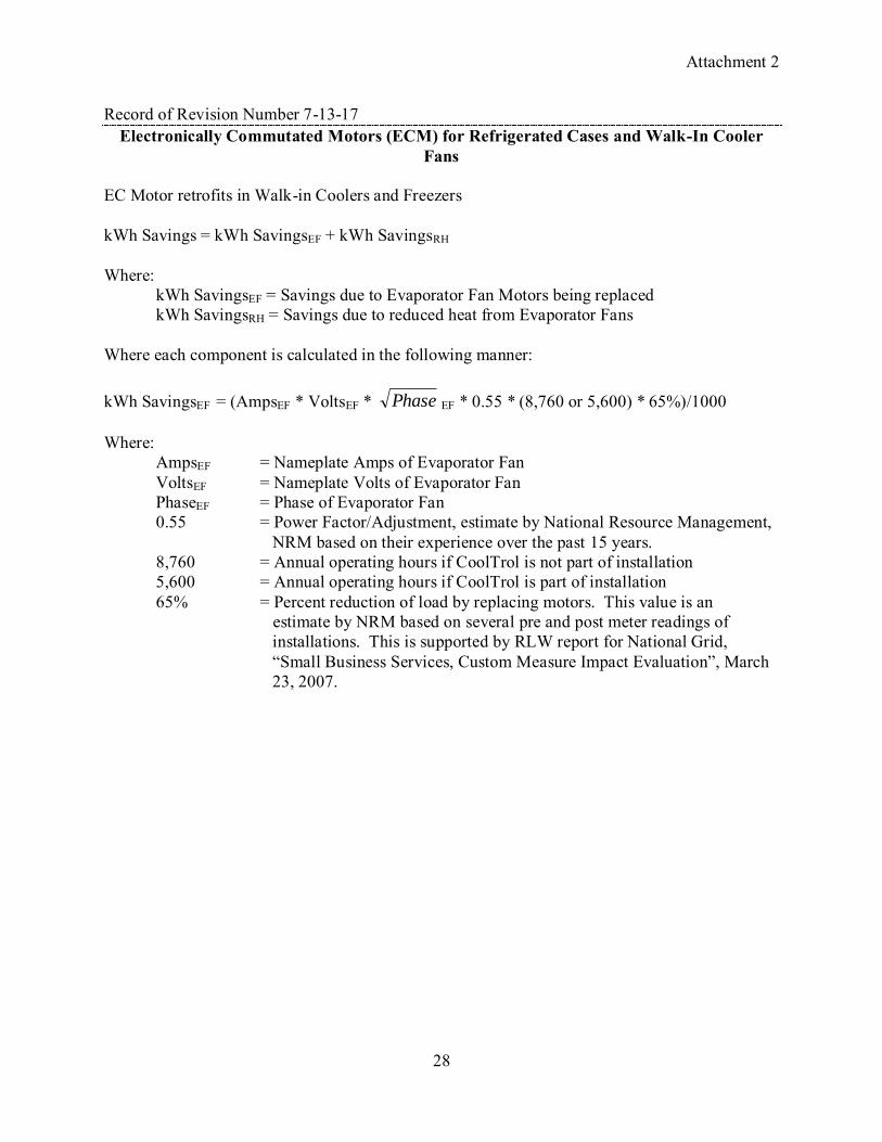
Record of Revision Number 7-13-17 Electronically Commutated Motors (ECM) for Refrigerated Cases and Walk-In Cooler
Fans EC Motor retrofits in Walk-in Coolers and Freezers kWh Savings = kWh SavingsEF + kWh SavingsRH Where: kWh SavingsEF = Savings due to Evaporator Fan Motors being replaced kWh SavingsRH = Savings due to reduced heat from Evaporator Fans Where each component is calculated in the following manner: kWh SavingsEF = (AmpsEF * VoltsEF * Phase EF * 0.55 * (8,760 or 5,600) * 65%)/1000 Where:
AmpsEF = Nameplate Amps of Evaporator Fan VoltsEF = Nameplate Volts of Evaporator Fan PhaseEF = Phase of Evaporator Fan 0.55 = Power Factor/Adjustment, estimate by National Resource Management, NRM based on their experience over the past 15 years. 8,760 = Annual operating hours if CoolTrol is not part of installation 5,600 = Annual operating hours if CoolTrol is part of installation 65% = Percent reduction of load by replacing motors. This value is an estimate by NRM based on several pre and post meter readings of installations. This is supported by RLW report for National Grid, “Small Business Services, Custom Measure Impact Evaluation”, March 23, 2007.

Attachment 2
29
Record of Revision Number 7-13-18 Appendix A: Prototypical Building Descriptions
Refrigerated Warehouse A prototypical building energy simulation model for a refrigerated warehouse building was developed using the DOE-2.2R4 building energy simulation program. The simulations were driven using TMY3 long-term average weather data. The characteristics of the prototype are summarized below.
Prototypical Refrigerated Warehouse Model Description Model Parameter Value
Vintage New construction Shape Rectangular (400 ft by 230 ft)
Floor area
Freezer: 40,000 SF Cooler: 40,000 SF Shipping Dock: 12,000 SF Total: 92,000 SF
Number of floors 1 Floor to ceiling height 30 ft Exterior wall construction Insulated metal panel
Ext wall R-Value Cooler and loading dock – R-20; Freezer – R-26
Record of Revision Number 7-13-19
Appendix A: Prototypical Building Descriptions
Hotel A prototypical building energy simulation model for a hotel building was developed using the DOE-2.2 building energy simulation program. The characteristics of the prototype are summarized below.
4 DOE-2.2R is a specialized version of the DOE-2.2 program, designed specifically to model refrigeration systems.

Attachment 2
30
Hotel Prototype Building Description Characteristic Value Vintage Existing (1970s) vintage Size 200,000 square feet total
Bar, cocktail lounge – 800 SF Corridor – 20,100 SF Dining Area – 1,250 SF Guest rooms – 160,680 SF Kitchen – 750 SF Laundry – 4,100 SF Lobby – 8,220 Office – 4,100 SF
Number of floors 11 Wall construction and R-value Block construction, R-7.5 Roof construction and R-value Wood deck with built-up roof, R-13.5 Glazing type Multi-pane; Shading-coefficient = 0.84
U-value = 0.72 Lighting power density Bar, cocktail lounge – 1.7 W/SF
Corridor – 1.0 W/SF Dining Area – 1.7 W/SF Guest rooms – 0.6 W/SF Kitchen – 4.3 W/SF Laundry – 1.8 W/SF Lobby – 3.1 W/SF Office – 2.2 W/SF
Plug load density Bar, cocktail lounge – 1.2 W/SF Corridor – 0.2 W/SF Dining Area – 0.6 W/SF Guest rooms – 0.6 W/SF Kitchen – 3.0 W/SF Laundry – 3.5 W/SF Lobby – 0.6 W/SF Office – 1.7 W/SF
Operating hours Rooms: 60% occupied 40% unoccupied All others: 24 hr / day
HVAC system type Central built-up system: All except corridors and rooms 1. Central constant volume system with perimeter hydronic reheat, without economizer; 2. Central constant volume system with perimeter hydronic reheat, with economizer; 3. Central VAV system with perimeter hydronic reheat, with economizer PTAC (Packaged Terminal Air Conditioner): Guest rooms PSZ: Corridors
HVAC system size Based on ASHRAE design day conditions, 10% over-sizing assumed. Minimum outdoor air fraction Built up system 0.3; PSZ: 0.14; PTAC: 0.11 is typical. Chiller type Water cooled and air cooled Chilled water system type Constant volume with 3 way control valves, Chilled water system control Constant CHW Temp, 45 deg F set point Boiler type Hot water, 80% efficiency Hot water system type Constant volume with 3 way control valves, Hot water system control Constant HW Temp, 180 deg F set point Thermostat set points Occupied hours: 76 cooling, 72 heating
Unoccupied hours: 81 cooling, 67 heating

Attachment 2
31
Record of Revision Number 7-13-20 Appendix A: Prototypical Building Descriptions
Commercial Building Prototypes Note: for purposes of applying the building type specific results to buildings not included in the prototype list, use the “other” category within each applicable measure savings section. Record of Revision Number 7-13-21
Appendix A: Prototypical Building Descriptions
Residential Building Prototypes Analysis used to develop parameters for the energy and demand savings calculations are based on DOE-2.2 simulations of a set of prototypical residential buildings. The prototypical simulation models were derived from the residential building prototypes used in the California Database for Energy Efficiency Resources (DEER)5 study, with adjustments made for local building practices and climate. Three separate models were created to represent general vintages of buildings:
1. Old, poorly insulated buildings constructed before 1979, before the NY State Energy Code went into effect. This vintage is referred to as the “old” vintage.
2. Existing, average insulated buildings conforming to 1980s era building codes. This vintage is referred to as the “average” vintage, covering buildings constructed from 1979 to 2006.
3. New construction conforming to the 2007 Energy Conservation Code of New York State for residential buildings. This vintage is referred to as the “new” vintage, and covers buildings constructed from 2007 to present.
Record of Revision Number 7-13-22 Weighting Factors for Commercial Building Calculations The Tech Manual currently lists energy savings estimates for small commercial buildings for a single vintage and HVAC system type, with the exception of HVAC interactive effects multipliers. Use the weights in the table below for HVAC interactive effects:
5 2004-2005 Database for Energy Efficiency Resources (DEER) Update Study, Final Report, Itron, Inc. Vancouver,
WA. December, 2005. Available at http://www.calmac.org/publications/2004-05_DEER_Update_Final_Report-Wo.pdf

Attachment 2
32
Building Type AC with gas heat
Heat Pump
AC with elec heat
Electric heat only
Gas heat only
Assembly 0.67 0.08 0.12 0.03 0.14 Auto Repair 0.61 0.08 0.10 0.04 0.24 Big Box 0.64 0.07 0.18 0.02 0.07 Elementary School 0.68 0.11 0.11 0.01 0.08 Fast Food 0.64 0.09 0.18 0.01 0.06 Full Service 0.64 0.09 0.18 0.01 0.06 Grocery 0.64 0.07 0.18 0.02 0.07
Light Industrial 0.46 0.06 0.15 0.10 0.37
Motel 0.53 0.15 0.17 0.02 0.07 Religious 0.59 0.11 0.13 0.03 0.15 Small Office 0.63 0.10 0.19 0.00 0.02 Small Retail 0.64 0.07 0.18 0.02 0.07 Warehouse 0.46 0.06 0.15 0.10 0.37 Other 0.60 0.09 0.16 0.03 0.14

Attachment 2
33
Record of Revision Number 7-13-23 Appendix C: Standard Fixture Watts
Shown below is first page only of Appendix C, See DPS website for entire Appendix C.
Reference: NYSERDA Existing Buildings Lighting Table with Circline Additions from CA SPC Table Fixture Code Lamp
Code Description Ballast Lamp/
Fixture Watt/ Lamp
Watt/ Fixtur
e
Compact Fluorescent Fixtures* Hard-
Wired or Pin-Based Only
CF10/2D CFD10W Compact Fluorescent, 2D, (1) 10W lamp Mag-STD 1 10 16 CF10/2D-L CFD10W Compact Fluorescent, 2D, (1) 10W lamp Electronic 1 10 12 CF11/1 CF11W Compact Fluorescent, (1) 11W lamp Mag-STD 1 11 13 CF11/2 CF11W Compact Fluorescent, (2) 11W lamp Mag-STD 2 11 26 CF16/2D CFD16W Compact Fluorescent, 2D, (1) 16W lamp Mag-STD 1 16 26 CF16/2D-L CFD16W Compact Fluorescent, 2D, (1) 16W lamp Electronic 1 16 18 CF18/3-L CF18W Compact Fluorescent, (3) 18W lamp Electronic 3 18 60 CF21/2D CFD21W Compact Fluorescent, 2D, (1) 21W lamp Mag-STD 1 21 26 CF21/2D-L CFD21W Compact Fluorescent, 2D, (1) 21W lamp Electronic 1 21 22 CF23/1 CF23W Compact Fluorescent, (1) 23W lamp Mag-STD 1 23 29 CF23/1-L CF23W Compact Fluorescent, (1) 23W lamp Electronic 1 23 25 CF26/3-L CF26W Compact Fluorescent, (3) 26W lamp Electronic 3 26 82 CF26/4-L CF26W Compact Fluorescent, (4) 26W lamp Electronic 4 26 108 CF26/6-L CF26W Compact Fluorescent, (6) 26W lamp Electronic 6 26 162 CF26/8-L CF26W Compact Fluorescent, (8) 26W lamp Electronic 8 26 216 CF28/2D CFD28W Compact Fluorescent, 2D, (1) 28W lamp Mag-STD 1 28 35 CF28/2D-L CFD28W Compact Fluorescent, 2D, (1) 28W lamp Electronic 1 28 28 CF32/3-L CF32W Compact Fluorescent, (3) 32W lamp Electronic 3 32 114 CF32/4-L CF32W Compact Fluorescent, (4) 32W lamp Electronic 4 32 152 CF32/6-L CF32W Compact Fluorescent, (6) 32W lamp Electronic 6 32 228 CF32/8-L CF32W Compact Fluorescent, (8) 32W lamp Electronic 8 32 304 CF28/2D CFD28W Compact Fluorescent, 2D, (1) 28W lamp Mag-STD 1 28 35 CF28/2D-L CFD28W Compact Fluorescent, 2D, (1) 28W lamp Electronic 1 28 28 CF32/3-L CF32W Compact Fluorescent, (3) 32W lamp Electronic 3 32 114 CF32/4-L CF32W Compact Fluorescent, (4) 32W lamp Electronic 4 32 152 CF32/6-L CF32W Compact Fluorescent, (6) 32W lamp Electronic 6 32 228 CF32/8-L CF32W Compact Fluorescent, (8) 32W lamp Electronic 8 32 304

Attachment 2
34
Record of Revision Number 7-13-24
Building: Single Family City: NYC HVAC: Gas Heat, no AC Measure: Roof Insulation Reff Base 0 11 19 30 38 Reff Measure
kWh/ kSF
kW/ kSF
therm/ kSF
kWh/ kSF
kW/ kSF
therm/ kSF
kWh/ kSF
kW/ kSF
therm/ kSF
kWh/ kSF
kW/ kSF
therm/ kSF
kWh/ kSF
kW/ kSF
therm/ kSF
11 105.6 0.0 224.4 19 118.4 0.0 252.6 12.8 0.0 28.2
30 125.9 0.0 268.8 20.3 0.0 44.4 7.5 0.0 16.2 38 128.8 0.0 275.1 23.2 0.0 50.7 10.4 0.0 22.5 2.9 0.0 6.3
49 131.4 0.0 280.7 25.8 0.0 56.3 13.0 0.0 28.2 5.5 0.0 11.9 2.6 0.0 5.6 60 133.1 0.0 284.3 27.5 0.0 59.9 14.7 0.0 31.7 7.2 0.0 15.5 4.3 0.0 9.2
Record of Revision Number 7-13-25
Appendix E. Opaque Shell Measure Savings
Single Family Residential Insulation Upgrades Note: R-values in Tables are effective R-values (Reff ) including adjustments for compression and installation quality.

Attachment 2
35
Record of Revision Number 7-13-26 Building: Single Family City: Binghamton HVAC: AC with Gas Heat Measure: Wall Insulation Reff Base 0 11 13 17 19
Reff Measure
kWh/ kSF kW/ kSF
therm/ kSF
kWh/ kSF kW/ kSF
therm/ kSF
kWh/ kSF kW/ kSF
therm/ kSF
kWh/ kSF kW/ kSF
therm/ kSF
kWh/ kSF kW/ kSF
therm/ kSF
11 46.2 0.043 54.0 13 54.3 0.054 62.6 8.1 0.011 8.7 17 64.3 0.065 74.8 18.1 0.022 20.8 10.0 0.011 12.1 19 67.4 0.065 79.2 21.2 0.022 25.3 13.1 0.011 16.6 3.1 0.000 4.4 21 71.0 0.076 82.9 24.8 0.033 28.9 16.7 0.022 20.3 6.7 0.011 8.1 3.6 0.011 3.7 25 75.4 0.076 88.7 29.3 0.033 34.7 21.1 0.022 26.0 11.2 0.011 13.9 8.0 0.011 9.4 27 77.5 0.076 90.9 31.3 0.033 37.0 23.2 0.022 16.2 13.2 0.011 16.2 10.1 0.011 11.7
Building: Single Family City: Binghamton HVAC: Heat Pump
Measure: Wall Insulation Reff Base 0 11 13 17 19
Reff Measure kWh/ kSF kW/ kSF kWh/ kSF kW/ kSF kWh/ kSF kW/ kSF kWh/ kSF kW/ kSF kWh/ kSF kW/ kSF 11 846.0 0.054 13 978.9 0.054 132.9 0.000 17 1165.7 0.065 319.7 0.011 186.9 0.011 19 1232.2 0.076 386.2 0.022 253.3 0.022 66.4 0.011 21 1288.1 0.076 442.1 0.022 309.2 0.022 122.4 0.011 55.9 0.000 25 1374.2 0.087 528.2 0.033 395.3 0.033 208.4 0.022 142.0 0.011 27 1407.8 0.087 561.8 0.033 242.0 0.033 242.0 0.022 175.6 0.011

Attachment 2
36
Building: Single Family City: Binghamton HVAC: AC with Electric Heat Measure: Wall Insulation Reff Base 0 11 13 17 19
Reff Measure kWh/ kSF kW/ kSF kWh/ kSF kW/ kSF kWh/ kSF kW/ kSF kWh/ kSF kW/ kSF kWh/ kSF kW/ kSF 11 1241.4 0.043 13 1440.0 0.054 198.6 0.011 17 1717.9 0.065 476.5 0.022 277.9 0.011 19 1818.7 0.065 577.3 0.022 378.7 0.011 100.8 0.000 21 1903.9 0.076 662.5 0.033 463.9 0.022 186.0 0.011 85.2 0.011 25 2035.0 0.076 793.6 0.033 595.1 0.022 317.1 0.011 216.3 0.011 27 2087.1 0.076 845.8 0.033 647.2 0.022 369.3 0.011 268.5 0.011
Building: Single Family City: Binghamton HVAC: Electric Heat, no AC Measure: Wall Insulation Reff Base 0 11 13 17 19
Reff Measure kWh/ kSF kW/ kSF kWh/ kSF kW/ kSF kWh/ kSF kW/ kSF kWh/ kSF kW/ kSF kWh/ kSF kW/ kSF 11 1222.6 0.000 13 1417.4 0.000 194.8 0.000 17 1691.4 0.000 468.8 0.000 274.0 0.000 19 1791.5 0.000 568.8 0.000 374.1 0.000 100.0 0.000 21 1874.9 0.000 652.3 0.000 457.5 0.000 183.5 0.000 83.5 0.000 25 2004.4 0.000 781.8 0.000 587.0 0.000 313.0 0.000 213.0 0.000 27 2055.6 0.000 833.0 0.000 638.2 0.000 364.2 0.000 264.1 0.000

Attachment 2
37
Building: Single Family City: Binghamton HVAC: Gas Heat, no AC Measure: Wall Insulation Reff Base 0 11 13 17 19
Reff Measure kWh/ kSF kW/ kSF
therm/ kSF kWh/ kSF kW/ kSF
therm/ kSF kWh/ kSF kW/ kSF
therm/ kSF kWh/ kSF kW/ kSF
therm/ kSF kWh/ kSF kW/ kSF
therm/ kSF
11 27.3 0.000 54.0 13 31.8 0.000 62.6 4.4 0.000 8.7 17 37.8 0.000 74.8 10.5 0.000 20.8 6.1 0.000 12.1 19 40.1 0.000 79.2 12.8 0.000 25.3 8.3 0.000 16.6 2.3 0.000 4.4 21 41.9 0.000 82.9 14.6 0.000 28.9 10.2 0.000 20.3 4.1 0.000 8.1 1.8 0.000 3.7 25 44.9 0.000 88.7 17.6 0.000 34.7 13.1 0.000 26.0 7.0 0.000 13.9 4.8 0.000 9.4 27 46.0 0.000 90.9 18.6 0.000 37.0 14.2 0.000 28.3 8.1 0.000 16.2 5.9 0.000 11.7
Building: Single Family City: Binghamton HVAC: AC with Gas Heat Measure: Roof Insulation Reff Base 0 11 19 30 38
Reff Measure kWh/ kSF kW/ kSF
therm/ kSF kWh/ kSF kW/ kSF
therm/ kSF kWh/ kSF kW/ kSF
therm/ kSF kWh/ kSF kW/ kSF
therm/ kSF kWh/ kSF kW/ kSF
therm/ kSF
11 311.4 0.290 332.9 19 350.9 0.341 374.4 39.4 0.051 41.5 30 369.8 0.358 398.8 58.4 0.068 65.9 18.9 0.017 24.4 38 377.1 0.375 408.2 65.7 0.085 75.3 26.3 0.034 33.8 7.3 0.017 9.4 49 385.2 0.392 416.6 73.7 0.102 83.6 34.3 0.051 42.2 15.4 0.034 17.7 8.0 0.017 8.4 60 389.4 0.392 422.0 78.0 0.102 89.1 38.6 0.051 47.6 19.6 0.034 23.2 12.3 0.017 13.8

Attachment 2
38
Building: Single Family City: Binghamton HVAC: Heat Pump Measure: Roof Insulation Reff Base 0 11 19 30 38
Reff Measure kWh/ kSF kW/ kSF kWh/ kSF kW/ kSF kWh/ kSF kW/ kSF kWh/ kSF kW/ kSF kWh/ kSF kW/ kSF 11 5853.1 0.273 19 6534.8 0.324 681.7 0.051 30 6923.9 0.358 1070.8 0.085 389.1 0.034 38 7075.4 0.358 1222.4 0.085 540.6 0.034 151.5 0.000 49 7208.7 0.375 1355.6 0.102 673.9 0.051 284.8 0.017 133.3 0.017 60 7294.7 0.375 1441.6 0.102 759.9 0.051 370.8 0.017 219.3 0.017
Building: Single Family City: Binghamton HVAC: AC with Electric Heat Measure: Roof Insulation Reff Base 0 11 19 30 38
Reff Measure kWh/ kSF kW/ kSF kWh/ kSF kW/ kSF kWh/ kSF kW/ kSF kWh/ kSF kW/ kSF kWh/ kSF kW/ kSF 11 7921.3 0.290 19 8887.9 0.341 966.6 0.051 30 9449.0 0.358 1527.6 0.068 561.1 0.017 38 9668.3 0.375 1746.9 0.085 780.4 0.034 219.3 0.017 49 9861.9 0.392 1940.6 0.102 974.1 0.051 413.0 0.034 193.7 0.017 60 9987.0 0.392 2065.7 0.102 1099.1 0.051 538.1 0.034 318.8 0.017
Building: Single Family City: Binghamton HVAC: Electric Heat, no AC Measure: Roof Insulation Reff Base 0 11 19 30 38
Reff Measure kWh/ kSF kW/ kSF kWh/ kSF kW/ kSF kWh/ kSF kW/ kSF kWh/ kSF kW/ kSF kWh/ kSF kW/ kSF 11 7775.8 0.000 19 8723.0 0.000 947.3 0.000 30 9277.1 0.000 1501.4 0.000 554.1 0.000 38 9493.9 0.000 1718.1 0.000 770.8 0.000 216.7 0.000 49 9683.4 0.000 1907.7 0.000 960.4 0.000 406.3 0.000 189.6 0.000 60 9807.0 0.000 2031.2 0.000 1084.0 0.000 529.9 0.000 313.1 0.000

Attachment 2
39
Building: Single Family City: Binghamton HVAC: Gas Heat, No AC Measure: Roof Insulation Reff Base 0 11 19 30 38
Reff Measure
kWh/ kSF kW/ kSF
therm/ kSF kWh/ kSF kW/ kSF
therm/ kSF
kWh/ kSF kW/ kSF
therm/ kSF
kWh/ kSF kW/ kSF
therm/ kSF
kWh/ kSF kW/ kSF
therm/ kSF
11 166.0 0.000 333.1 19 186.3 0.000 374.6 20.3 0.000 41.5 30 198.1 0.000 398.8 32.1 0.000 65.7 11.8 0.000 24.2 38 202.7 0.000 408.4 36.7 0.000 75.3 16.4 0.000 33.8 4.6 0.000 9.6 49 206.8 0.000 416.7 40.8 0.000 83.6 20.5 0.000 42.2 8.7 0.000 17.9 4.1 0.000 8.4 60 209.4 0.000 422.2 43.3 0.000 89.1 23.0 0.000 47.6 11.3 0.000 23.4 6.7 0.000 13.8
Record of Revision Number 7-13-27
Appendix H: Residential Distribution System Efficiency in Cooling Mode (Attic Ducts)

Attachment 2
40
Record of Revision Number 7-13-28 Engine Block Heater Timers
Description of Measure
This section covers timers used to control engine block heaters on farm equipment engines such as tractors, skid steers, truck, generators, and so on. The timers are used to control existing engine block heaters. Method for Calculating Summer Peak Demand and Energy Savings
ΔkWs = 0
where:
ΔkWs = gross summer coincident demand savings
ΔkWh = gross annual energy savings units = number of timers installed under the program Wattsheater = wattage of engine block heater hr/daybase = avg hours per day heater plugged in hr/daytimer = avg hours per day timer turns the heater on day/yr = number of days per year heater is used
Wattsheater is defined as the wattage of the engine block heater under control. This value is recorded by the customer on the application. hr/daybase is defined as the average number of hours the engine block heater is plugged in and active before the installation of the timer. This value is recorded by the customer on the application. hr/daytimer is defined as the number of hours the engine block heater is controlled on by the timer. The on time and off time are set by the user. The number of hours required to sufficiently warm the engine depends on the size (mass) of the engine, the heating capacity of the heater and the environmental temperature. Estimates of 1 to 4 hours of block heater operation are common in the literature. A deemed value of 2.0 hours per day shall be used (1). day/yr is defined as the number of days in the year the heater is used. This value is calculated from the customer reported heater use start and end date on the application.

Attachment 2
41
Baseline Efficiencies from which Savings are Calculated
The baseline condition is assumed to be the existing engine block heater plugged in and operational during the hours reported by the customer. Compliance Efficiency from which Incentives are Calculated
The measure is defined as the existing block heater controlled by the timer. Timer on hours are set by the customer. A deemed value of 2.0 hours per day shall be used. Non-Electric Benefits - Annual Fossil Fuel Savings
None expected.
Summary of Variables and Data Sources
Variable Value Notes
Units From application. Wattsheater From application hr/daybase From application hr/daytimer 2.0 Deemed value for timer operation day/yr From application
Notes & References
1. Deemed value for timer operation taken from Wisconsin Public Service calculator for tractor heater timers. See http://www.wisconsinpublicservice.com/business/farm_tractor.aspx
Attachment 2
42
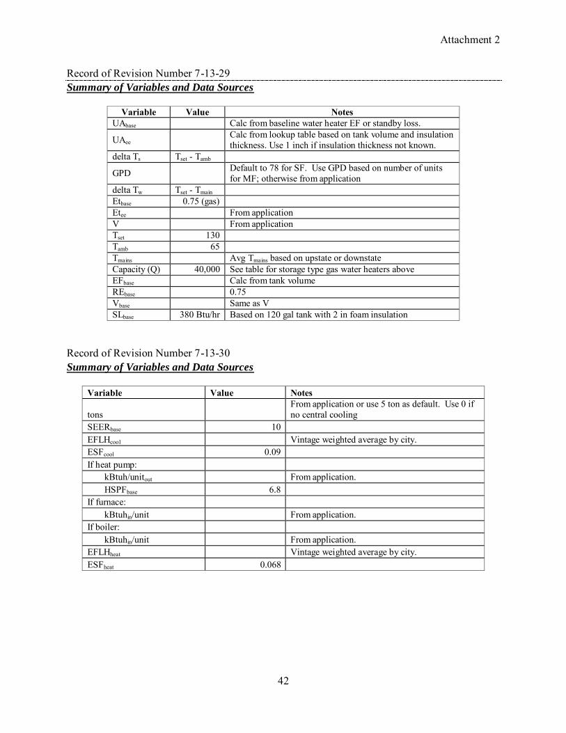
Record of Revision Number 7-13-29 Summary of Variables and Data Sources
Variable Value Notes
UAbase Calc from baseline water heater EF or standby loss.
UAee Calc from lookup table based on tank volume and insulation thickness. Use 1 inch if insulation thickness not known.
delta Ts Tset - Tamb
GPD Default to 78 for SF. Use GPD based on number of units for MF; otherwise from application
delta Tw Tset - Tmain Etbase 0.75 (gas) Etee From application V From application Tset 130 Tamb 65 Tmains Avg Tmains based on upstate or downstate Capacity (Q) 40,000 See table for storage type gas water heaters above EFbase Calc from tank volume REbase 0.75 Vbase Same as V SLbase 380 Btu/hr Based on 120 gal tank with 2 in foam insulation
Record of Revision Number 7-13-30 Summary of Variables and Data Sources
Variable Value Notes
tons From application or use 5 ton as default. Use 0 if no central cooling
SEERbase 10 EFLHcool Vintage weighted average by city. ESFcool 0.09 If heat pump:
kBtuh/unitout From application. HSPFbase 6.8
If furnace: kBtuhin/unit From application.
If boiler: kBtuhin/unit From application.
EFLHheat Vintage weighted average by city. ESFheat 0.068

Attachment 2
43
Record of Revision Number 7-13-31 Evaporator Fan Controls
Description of Measure
Walk-in cooler and freezer evaporator fans often run continually, requiring more air to be blown across the evaporator than needed to cool the evaporator. This measure consists of a control system that turns the fan on only when the unit‟s thermostat is calling for the compressor to operate, shutting the fan off shortly after the desired temperature is reached and the compressor is turned off. Savings Estimation Approach
The savings from this measure is highly dependent on the type, size and condition of the coolers and freezers fitted with fan controls. As a result an estimate of the typical unit must be based on the program‟s projection of what types and sizes of units will be served and the condition of those units to function. In general the following estimate approach must be made for the typical units that the program is expected to control: kWh = kWh EF + kWh RH + kWh EC where: kWh EF = Savings due to Evaporator Fan being off kWh RH = Savings due to reduced heat from Evaporator Fans kWh EC = Savings due to the electronic controls on compressor and evaporator
kWh EF = kWfan * FLHfan * Foff where: kWfan = Fan kW =( V * A * (phase )0.5 * PFfan)/1000 Vfan = nameplate fan volts Afan = nameplate fan amps Phasefan = number of phases (1 or 3) PFfan = power factor for fan motor FLHfan = Annual operating hours Foff = Fraction of time that Evaporator Fan is turned off.
Attachment 2
44
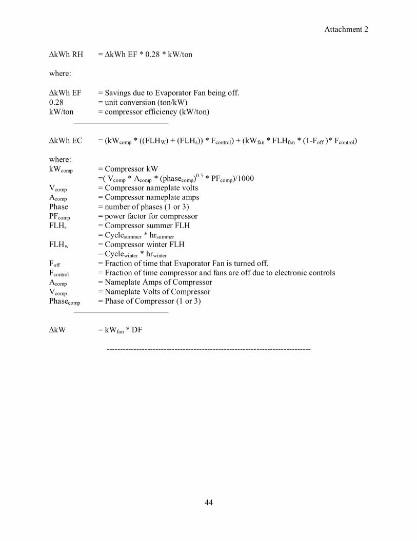
kWh RH = kWh EF * 0.28 * kW/ton where: kWh EF = Savings due to Evaporator Fan being off. 0.28 = unit conversion (ton/kW) kW/ton = compressor efficiency (kW/ton)
kWh EC = (kWcomp * ((FLHW) + (FLHs)) * Fcontrol) + (kWfan * FLHfan * (1-Foff )* Fcontrol) where: kWcomp = Compressor kW =( Vcomp * Acomp * (phasecomp)0.5 * PFcomp)/1000 Vcomp = Compressor nameplate volts Acomp = Compressor nameplate amps Phase = number of phases (1 or 3) PFcomp = power factor for compressor FLHs = Compressor summer FLH = Cyclesummer * hrsummer FLHw = Compressor winter FLH = Cyclewinter * hrwinter Foff = Fraction of time that Evaporator Fan is turned off. Fcontrol = Fraction of time compressor and fans are off due to electronic controls Acomp = Nameplate Amps of Compressor Vcomp = Nameplate Volts of Compressor Phasecomp = Phase of Compressor (1 or 3)
kW = kWfan * DF
---------------------------------------------------------------------------

Attachment 2
45
Electronically Commutated Motors (ECM) for Refrigerated Cases and Walk-In Cooler Fans
EC Motor retrofits in Walk-in Coolers and Freezers kWh Savings = kWh SavingsEF + kWh SavingsRH Where: kWh SavingsEF = Savings due to Evaporator Fan Motors being replaced kWh SavingsRH = Savings due to reduced heat from Evaporator Fans Where each component is calculated in the following manner: kWh SavingsEF = (AmpsEF * VoltsEF * Phase EF * 0.55 * (8,760 or 5,600) * 65%)/1000 Where:
AmpsEF = Nameplate Amps of Evaporator Fan VoltsEF = Nameplate Volts of Evaporator Fan PhaseEF = Phase of Evaporator Fan 0.55 = Power Factor/Adjustment, estimate by National Resource Management, NRM based on their experience over the past 15 years. 8,760 = Annual operating hours if Cooltrol is not part of installation 5,600 = Annual operating hours if Cooltrol is part of installation 65% = Percent reduction of load by replacing motors. This value is an estimate by NRM based on several pre and post meter readings of installations. This is supported by RLW report for National Grid, “Small Business Services, Custom Measure Impact Evaluation”, March 23, 2007. And: kWh SavingsRH - (Savings due to reduced heat from fan motors) = kWh SavingsEF * 0.28 * 1.6 Where: kWh SavingsEF = Savings due to Evaporator Fans being replaced (see above) 0.28 = unit conversion between kW and tons, See LED lighting Calculation for derivation 1.6 = Efficiency of typical refrigeration system, units are kW/ton

Attachment 2
46
Refrigerated Case Motor Replacement kWh Savings = (Annual motor kW A * 53% or 29% * 8,500) + Refrigeration savings
due to reduced heat load from new motors. Where:
kW A = metered load of case motors 53% = energy reduction if a shaded pole motors is being replaced. Based on numerous pre and post meterings conducted by NRM 29% = energy reduction if a PSC motor is being replaced. Based on numerous pre and
post meterings conducted by NRM 8,500 = average runtime of case motors
Refrigeration Savings - (Savings due to reduced heat from fan motors) = kWh SavingsCM * 0.28 * 1.6 Where: kWh SavingsCM = Savings due to Case Motors being replaced (see above).
0.28 = unit conversion between kW and tons, see LED Lighting Calculation for derivation of value
1.6 = Efficiency of typical refrigeration system, units are kW/ton Record of Revision Number 7-13-32
Boilers
Description of Measure
High efficiency condensing and non-condensing gas-fired hot water and steam boilers in single family and multi-family buildings. Method for Calculating Energy Savings
therms = units 100
1unit
kBtuhin heat
base
ee EFLH
-----------------------------------------------------------------------------

Attachment 2
47
High Efficiency Gas Furnaces
Description of Measure
This section covers high efficiency condensing gas furnaces with an AFUE > 92% in single family and multi-family applications. Method for Calculating Energy Savings
therms = units100
1unit
kBtuhin heat
base
ee EFLH
AFUE
AFUE
Record of Revision Number 7-13-33
Indirect Water Heaters Indirect water heaters are tank-type water heaters that are indirectly heated by hot water from a boiler rather than direct input from electric elements or gas burners. A heat exchanger separates the potable water in the water heater from the boiler water. The baseline assumption for indirect water heaters is a standard efficiency tank type water heater or an indirect system with a standard efficiency boiler.
Method for Calculating Energy Savings
therm =
8760
000,100)(11
000,1003.8365
,,,,
s
eet
ee
baset
base
eetbaset
w T
E
UA
E
UA
EE
TGPDunits
UAbase =
basebase
basebase
CapRE
REEF
1000584.05.67
11
EFbase = 0.62-0.0019Vbase

Attachment 2
48
Record of Revision Number 7-13-34 Using the default values above, the tank UA for typical gas water heaters are shown in the Table below:
Water Heater Size Gas Water Heater Tank UA 40 13.6 80 21.6
120 32.8 Tank overall heat loss coefficient (UA) for larger multi-family water heaters is calculated from the standby loss specification.
------------------------------------------------------------------------------- Larger tank UA values are shown below.
Water heater size
(gal) Height
(in) Diameter
(in)
UA (Btu/hr-F) Bare tank
Fiberglass Foam 1 in 2in 1 in 2in
140 76 24 47.9 12.0 6.2 9.6 4.9 200 72 30 60.9 14.7 7.6 11.7 6.0 250 84 30 68.1 16.8 8.6 13.3 6.9 350 88 36 88.8 21.5 11.0 17.1 8.7 400 97 36 95.3 23.3 11.9 18.5 9.5 500 74 48 115.9 26.3 13.3 20.9 10.6 750 106 48 146.9 34.9 17.7 27.7 14.1
1000 138 48 177.9 43.5 22.1 34.6 17.6 Record of Revision Number 7-13-35 Standard assumptions for recovery efficiency and input capacity for small non-condensing water heaters6 are:
Water Heater Type Recovery efficiency Capacity (Btu/hr) Gas 0.75 40,000
6 Values applicable to non-condensing water heaters with EF 0.68.

Attachment 2
49
Record of Revision Number 7-13-36 Water Heater
Description of Measure
Efficient instantaneous and storage type water heaters installed in whole-house applications. Method for Calculating Energy Savings
kWs = ss
seebase CFDFTUAUA
units
3412
)(
kWh =
COPEF
TGPDunits
base
113412
33.8365
therm =
eebase
w
EFEF
TGPDunits
11000,100
3.8365
---------------------------------------------------------------------------------
Water Heaters Description of Measure
Efficient water heaters installed in whole-building applications. Method for Calculating Energy Savings
kWs = ssseebase CFDF
3412DT)UA-(UAunits
kWh =
eetbaset
w
EE
TGPDunits
,,
113412
33.8365
therm =
eetbaset
w
EE
TGPDunits
,,
11000,100
33.8365

Attachment 2
50
Record of Revision Number 7-13-37 This relationship was used to adjust the New England data for New York locations, as shown below:
City CDH(65)/24 Cooling EFLH Albany 716 181 Binghamton 517 120 Buffalo 619 151 Massena 592 143 NYC 1374 382 Poughkeepsie 804 208 Syracuse 734 186
Record of Revision Number 7-13-38
Opaque Shell Insulation Description of Measure
This section covers improvements to the thermal conductance of the opaque building shell, which includes upgrading insulation in walls, ceilings, floors, etc. Energy and demand saving are realized through reductions in the building heating and cooling loads. Method for Calculating Summer Peak Demand and Energy Savings
kWs = SF (kW/SF) CFs coolpartpkdist
basepkdist
part
base
EER
EER
,,
,,
kWh = SF (kWh/SF) coolpartdist
basedist
part
base
SEER
SEER
,
,
therm = SF (therm/SF) heatpartdist
basedist
part
base
AFUE
AFUE
,
,
where: EERbase = EER used in the simulations EERpart = EER of cooling systems within participant population SEERbase = SEER used in the simulations SEERpart = SEER of cooling system within participant population AFUEbase = AFUE used in the simulations AFUEpart = AFUE of heating system within participant population dist,base = distribution system seasonal efficiency used in simulations dist,part = distribution system seasonal efficiency within participant population

Attachment 2
51
dist,pk,base = distribution system efficiency under peak conditions used in simulation
dist,pk,part = distribution system efficiency under peak conditions within participant
population CFs = Peak coincidence factor (summer) Record of Revision Number 7-13-39 Method for Calculating Summer Peak Demand and Energy Savings
kWs = units tons
unit eebase tonkWtonkW // CFs
kWh = units tons
unit eebase IPLVIPLV EFLHcooling
where: kW = gross coincident demand savings kWh = gross annual energy savings units = the number of air conditioning units installed under the program tons/unit = tons of air conditioning per unit, based on nameplate data IPLV = annual average chiller efficiency (kW/ton) kW/ton = full load chiller efficiency under peak conditions EFLHcooling = cooling equivalent full-load hours CF = coincidence factor The rated full load kW/ton at ARI rating conditions is used to define the efficiency under peak conditions. The IPLV as defined by ARI is used to define the annual average efficiency. These values represent average conditions across the US, and will be used until data specific to New York can be developed. Note, chiller full load efficiency or IPLV may also be expressed as coefficient of performance (COP). To convert chiller efficiency from COP to kW/ton, use the following equation: kW/ton = 3.516 / COP IPLV(kw/ton) = 3.516 / IPLV(COP)
Cooling equivalent full-load hours (EFLH) are defined as the ratio of the annual building cooling energy to the nameplate capacity:
EFLHcool = A
kWpeak
nnual kWh cooling
cooling,
Cooling equivalent full load hours were calculated from a DOE-2.2 simulation of prototypical large office building. The prototype building characteristics are described in Appendix A. The CLH for built-up HVAC systems in commercial buildings in various NY locations are shown in Appendix G.

Attachment 2
52
The coincidence factor is used to account for the fact that not all HVAC systems in all buildings in the population are operating at the same time. The coincidence factor is defined as the average fraction of installed capacity of a population of HVAC systems that are operating at the time of the system peak.
Recommended value for the coincidence factor is shown below.
Parameter Recommended Values Coincidence factor 0.8
Baseline Efficiencies from which Savings are Calculated
The baseline efficiency for new construction varies by equipment type and size, and is shown in the table below.
Baseline Performance Assumptions Equipment Category Capacity Range
Baseline Efficiency (kw/ton)
Baseline Efficiency (COP)
Average Peak Average Peak Air Cooled Chiller All 1.15 1.26 3.05 2.8 Water cooled Recip All 0.70 0.84 5.05 4.2
Water cooled screw and scroll
< 150 tons 0.68 0.79 5.2 4.45 150 – 300 tons 0.63 0.72 5.6 4.9 > 300 tons 0.57 0.64 6.15 5.5
Water cooled centrifugal
< 150 tons 0.67 0.70 5.25 5.00 150 – 300 tons 0.60 0.63 5.90 5.55 > 300 tons 0.55 0.58 6.40 6.10
Record of Revision Number 7-13-40 See Record of Revision Number 7-13-30 above.
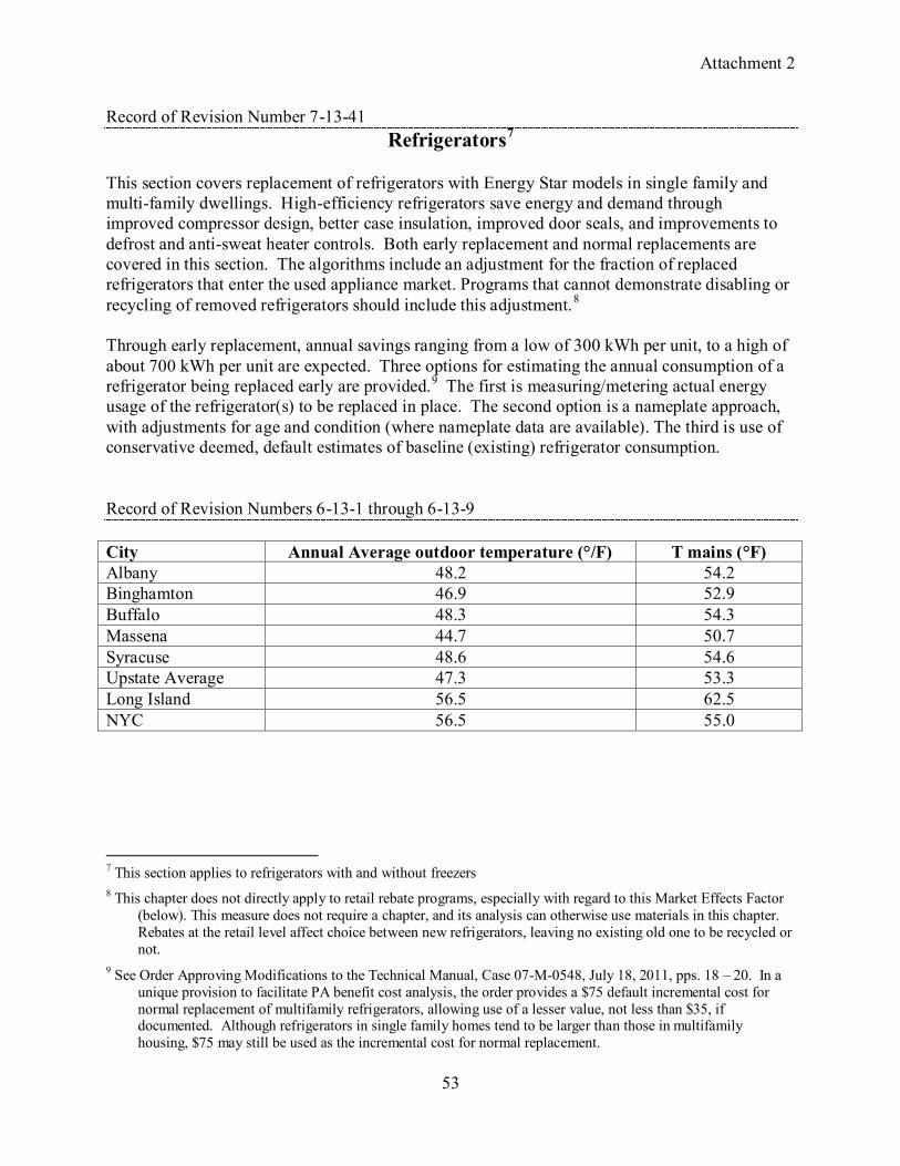
Attachment 2
53
Record of Revision Number 7-13-41 Refrigerators7
This section covers replacement of refrigerators with Energy Star models in single family and multi-family dwellings. High-efficiency refrigerators save energy and demand through improved compressor design, better case insulation, improved door seals, and improvements to defrost and anti-sweat heater controls. Both early replacement and normal replacements are covered in this section. The algorithms include an adjustment for the fraction of replaced refrigerators that enter the used appliance market. Programs that cannot demonstrate disabling or recycling of removed refrigerators should include this adjustment.8 Through early replacement, annual savings ranging from a low of 300 kWh per unit, to a high of about 700 kWh per unit are expected. Three options for estimating the annual consumption of a refrigerator being replaced early are provided.9 The first is measuring/metering actual energy usage of the refrigerator(s) to be replaced in place. The second option is a nameplate approach, with adjustments for age and condition (where nameplate data are available). The third is use of conservative deemed, default estimates of baseline (existing) refrigerator consumption. Record of Revision Numbers 6-13-1 through 6-13-9 City Annual Average outdoor temperature (°/F) T mains (°F) Albany 48.2 54.2 Binghamton 46.9 52.9 Buffalo 48.3 54.3 Massena 44.7 50.7 Syracuse 48.6 54.6 Upstate Average 47.3 53.3 Long Island 56.5 62.5 NYC 56.5 55.0
7 This section applies to refrigerators with and without freezers 8 This chapter does not directly apply to retail rebate programs, especially with regard to this Market Effects Factor
(below). This measure does not require a chapter, and its analysis can otherwise use materials in this chapter. Rebates at the retail level affect choice between new refrigerators, leaving no existing old one to be recycled or not.
9 See Order Approving Modifications to the Technical Manual, Case 07-M-0548, July 18, 2011, pps. 18 – 20. In a unique provision to facilitate PA benefit cost analysis, the order provides a $75 default incremental cost for normal replacement of multifamily refrigerators, allowing use of a lesser value, not less than $35, if documented. Although refrigerators in single family homes tend to be larger than those in multifamily housing, $75 may still be used as the incremental cost for normal replacement.

Attachment 2
54
Record of Revision Numbers 3-13-1 Appendix O: C&I Lighting Policy
See DPS Website Record of Revision Numbers 5-11-1
Appendix M: Guidelines for Early Replacement Conditions
See DPS Website