june 2013 no
TRANSCRIPT

CONTENTS
SCIENTIFIC AND TECHNICALGolovko V.V. and Pokhodnya I.K. Effect of non-metallicinclusions on formation of structure of the weld metal inhigh-strength low-alloy steels ............................................................... 2
Makhnenko V.I., Olejnik O.I. and Shekera V.M. Determinationof contact pressure of reinforcing sleeve in repair of pipelineswith surface defects ............................................................................ 11
Pokhmursky V.I., Student M.M., Pokhmurskaya A.V., RyabtsevI.A., Gvozdetsky V.M. and Stupnitsky T.R. Gasoabrasive wearresistance at elevated temperatures of coatings produced bythermal spraying ................................................................................. 15
Pantelejmonov E.A. and Nyrkova L.I. Application of inductionheat treatment to provide corrosion resistance of stainlesssteel welded pipes .............................................................................. 23
INDUSTRIALMakhlin N.M., Popov V.E., Fedorenko N.S., Burba A.V.,Pyshny V.M., Dyukov V.A. and Gontarev V.B. Application ofautomatic orbital welding in manufacture of housings ofneutron measurement channels of nuclear reactors ............................. 28
Goloborodko Zh.G., Dragan S.V. and Simutenkov I.V.Automatic submerged arc surfacing of structural steels withtransverse high-frequency movements of electrode ............................. 34
Nesterenkov V.M., Kravchuk L.A., Arkhangelsky Yu.A. andBondarev A.A. Welds formation in EBW of heat-resistant steelsof the grades 10Kh9MFBA and 10Kh12M ............................................ 38
Kuznetsov V.D., Stepanov D.V., Makovej V.A. and ChernyakYa.P. Wear resistance of deposited metal of the type ofcarbon and chromium-manganese steels under the conditionsof dry sliding friction of metal over metal ............................................. 43
BRIEF INFORMATIONFalchenko Yu.V., Polovetsky E.V. and Kapitanchuk L.M.Distribution of chemical elements in the zone of aluminiumalloy AMg6 to titanium alloy VT6 joints produced by diffusionwelding in vacuum .............................................................................. 46
«The Paton Welding Journal» abstracted and indexed in Ukrainian refereedjournal «Source», RJ VINITI «Welding» (Russia), INSPEC, «Welding
Abstracts», ProQuest (UK), EBSCO Research Database, CSA MaterialsResearch Database with METADEX (USA), Questel Orbit Inc. WeldasearchSelect (France); presented in Russian Science Citation Index & «Google
Scholar»; abstracted in «Welding Institute Bulletin» (Poland) & «Rivista Italianadella Saldatura» (Italy); covered in the review of the Japanese journals
«Journal of Light Metal Welding», «Journal of the Japan Welding Society»,«Quarterly Journal of the Japan Welding Society», «Journal of Japan Institute
of Metals», «Welding Technology».
English translation of the monthly «Avtomaticheskaya Svarka» (Automatic Welding) journal published in Russian since 1948
Editor-in-Chief B.E.Paton
EDITORIAL BOARDYu.S. Borisov, A.Ya. Ishchenko,
B.V. Khitrovskaya (exec. secretary),V.F. Khorunov, I.V. Krivtsun,
S.I. Kuchuk-Yatsenko (vice-chief editor),V.I. Kyrian, Yu.N. Lankin,
V.N. Lipodaev (vice-chief editor),L.M. Lobanov, A.A. Mazur,
O.K. Nazarenko, I.K. Pokhodnya,V.D. Poznyakov, I.A. Ryabtsev,
K.A. Yushchenko,A.T. Zelnichenko (exec. director)
INTERNATIONAL EDITORIALCOUNCIL
N.P.Alyoshin (Russia)Guan Qiao (China)
V.I.Lysak (Russia)B.E.Paton (Ukraine)
Ya.Pilarczyk (Poland)O.I. Steklov (Russia)G.A.Turichin (Russia)M. Zinigrad (Israel)
A.S.Zubchenko (Russia)
FoundersE.O. Paton Electric Welding Institute
of the NAS of Ukraine,International Association «Welding»
PublisherInternational Association «Welding»
Translators:A.A.Fomin, O.S.Kurochko,
I.N.Kutianova, T.K.VasilenkoEditor
N.A.DmitrievaElectron galley
D.I.Sereda, T.Yu.Snegiryova
AddressE.O. Paton Electric Welding Institute,International Association «Welding»
11, Bozhenko Str., 03680, Kyiv, UkraineTel.: (38044) 200 60 16, 200 82 77Fax: (38044) 200 82 77, 200 81 45
E-mail: [email protected]
URL: www.rucont.ru
State Registration CertificateKV 4790 of 09.01.2001
ISSN 0957-798X
Subscriptions$348, 12 issues per year,
air postage and packaging included.Back issues available.
All rights reserved.This publication and each of the articles
contained herein are protected by copyright.Permission to reproduce material contained inthis journal must be obtained in writing from
the Publisher.
June 2013No.6
Published since 2000
E.O. Paton Electric Welding Institute of the National Academy of Sciences of Ukraine
International Scientific-Technical and Production Journal
© PWI, International Association «Welding», 2013

EFFECT OF NON-METALLIC INCLUSIONSON FORMATION OF STRUCTURE OF THE WELD METAL
IN HIGH-STRENGTH LOW-ALLOY STEELS
V.V. GOLOVKO and I.K. POKHODNYAE.O. Paton Electric Welding Institute, NASU,
11 Bozhenko Str., 03680, Kiev, Ukraine. E-mail: [email protected]
Investigated was the possibility of using the oxide metallurgy approaches providing for control of theamount, distribution and morphology of the inclusions in metal melts, which affect conditions for formationof microstructure of the weld metal. It was shown that increase in the content of the fine-grained secondaryphase can be achieved by varying the content of the fine carbide phase in structure of the weld metal. Ahigh density of distribution of the 0.3—1.0 μm inclusions containing titanium or zirconium oxides leads toformation of the bainitic structure, whereas the decreased content of carbon in metal and narrowing of therange of bainitic transformations limit the probability of formation of the upper bainite microstructure. Itwas found that to provide the microstructure characterised by a combination of high values of strength,ductility and toughness it is necessary to form inclusions of a certain composition, size and distributiondensity in the weld metal. This can be achieved by using the oxide metallurgy methods, which provide foraddition of a certain amount of refractory inclusions to the weld pool, limitation of its oxygen content andselection of the deoxidation system, as well as of the required temperature range of intermediate transfor-mations based on the TTT-diagrams and welding thermal cycle. 12 Ref., 9 Tables, 13 Figures.
Keywo r d s : welding, low-alloy steels, oxide metal-lurgy, welds, non-metallic inclusions, alloying, micro-structure, mechanical properties
High-strength low-alloy (HSLA) steels havebeen receiving an increasingly wider acceptancein fabrication of metal structures during the lastdecades. Along with expansion of the scopes ofconsumption of this class of steels, we can noteincreasing requirements to the level of their me-chanical properties, brittle fracture resistanceand cost effectiveness. For example, a growingconsumption of the natural gas by developedcountries dictates increase in the working pres-sure of a transported gas from 55—75 to 100 ormore, the growth of which in pipelines madefrom steels of strength category K60 (X70) leadsto increase in metal intensity and specific costs.This is accompanied by increase in the level ofrequirements to operating safety, reliability andservice life of pipelines, which in turn requiresincrease in impact toughness and brittle fractureresistance, as well as improvement of weldabilityof the said steels.
Transition from steels of strength categoriesK60 (X70) to steels K65 (X80) and strongerrequired revision of the principles of alloying andmicroalloying them from the metal science stand-points. Providing the required level of strengthof sheet and plate products in a combination withother most important indices of mechanical prop-
erties (δ5 > 22 %, KCV > 130 J/cm2, and contentof tough components in fractures of drop-weighttest specimens > 95 % at —20 °C) is possible onlyin transition from the ferritic-pearlitic structure tothe other structural state of a material, i.e. steelswith the fine ferritic-bainitic structure [1, 2].
To ensure the required level of performanceof welded metal structures, chemical and struc-tural compositions, as well as mechanical prop-erties of the weld metal should correspond tothose of the base metal. The problem of formationof the weld metal with the ferritic-bainitic struc-ture can be solved by using the possibilities of-fered by oxide metallurgy [3, 4].
The necessary condition for formation of thehigh-toughness fine structure of the type of acicu-lar ferrite is the presence of a certain amount ofnon-metallic inclusions (NMI) in the weld metal[5, 6]. It should be noted that inclusions up to1 μm in size, which contain titanium compounds,are most efficient in this respect [7—9].
The use of the oxide metallurgy approachesallows affecting the processes of initiation andgrowth of structural components by varying thecomposition, content and sizes of NMI [10, 11].Investigation of the effect of NMI on the secon-dary microstructure was carried out on specimensof the weld metal of low-alloy steel of strengthcategory K60 alloyed with carbon, manganeseand silicon, with an adjustable content of oxygenand microalloyed with titanium. The welds were
© V.V. GOLOVKO and I.K. POKHODNYA, 2013
2 6/2013

made by the method of submerged-arc welding(welding heat input – about 33.4 kJ/cm). Inthis case the main part of oxygen transfers to theweld pool through the slag phase, as the distri-bution of oxygen between the slag and pool isdetermined by a ratio of the activity of oxygenin the slag (aO) to the activity of oxygen in theweld pool metal [aO]. Considering that the con-tent of oxygen in metal is low and the [aO] valueis close to one, the transition of oxygen dependsonly on (aO).
Chemical composition of metal of the inves-tigated welds is given in Table 1, and its me-chanical properties are given in Table 2.
Results of dilatometric investigations of theweld metal conducted by using the «Gleeble»high-speed dilatometer are shown in Figure 1.Composition of the microstructure componentsand their sizes were determined by using opticalmicroscope «Neophot 30» (Table 3).
It was found that growth of the content oftitanium in the weld metal is accompanied byincrease in temperature of the finish of bainitictransformation Bf and decrease in the γ → α trans-formation temperature range. Proportion of thetitanium and oxygen in the weld metal affectsthe balance between the content of the inclusionsabove 1 μm in size consisting primarily of oxides
(Figure 2)*, and that of the inclusions less than1 μm in size consisting of carbides (Figure 3).Increase in the content of fine carbides leads toincrease in the content of upper bainite in thesecondary structure of the weld metal (see Ta-ble 3). This causes increase in strength and de-crease in impact toughness of the weld metal (seeTable 2) due to an increased brittleness of thegiven structural component.
Alloying of the weld metal with titanium al-lows the size of the ferritic grains to be substan-
Figure 1. Dependence of temperature range of structural trans-formations in metal of the investigated welds on the titaniumcontent: Fs, Ff – start and finish of ferritic transformation;Bs, Bf – start and finish of bainitic transformation
Table 1. Chemical composition of metal of the investigated welds, wt.%
Welddesignation
C Si Mn Ni Mo Ti Cr Al S P O
Ti-1 0.078 0.437 0.43 0.22 0.19 0.027 0.24 0.012 0.008 0.009 0.101
Ti-2 0.073 0.227 0.48 0.24 0.19 0.084 0.25 0.019 0.007 0.010 0.054
Ti-3 0.075 0.181 0.54 0.23 0.19 0.127 0.25 0.028 0.006 0.009 0.032
Ti-4 0.125 0.557 0.47 0.22 0.17 0.130 0.23 0.029 0.011 0.008 0.102
Ti-5 0.083 0.389 0.51 0.24 0.18 0.244 0.26 0.039 0.008 0.010 0.030
Ti-6 0.118 0.217 0.52 0.21 0.16 0.297 0.22 0.054 0.007 0.008 0.022
Table 2. Mechanical properties of metal of the investigated welds
Weld designation σt, MPa σ0.2, MPa δ5, % ψ, %KCV, J/cm2, at T, °С
20 0 —20
Ti-1 597.5 437.7 23.15 58.8 62.4 42.9 23.7
Ti-2 603.5 443.4 23.5 67.7 64.3 40.8 19.0
Ti-3 665.9 527.2 18.8 66.9 43.3 20.9 13.8
Ti-4 807.3 664.2 17.6 66.0 22.2 16.7 13.0
Ti-5 769.0 673.3 17.5 68.9 28.5 13.8 16.0
Ti-6 634.0 488.9 20.6 59.8 49.6 18.3 13.9
*The pictures in Figures 2 and 3 were obtained by Prof. V.N. Tkachby using scanning electron microscope EVO-50.
6/2013 3

tially decreased (see Table 3). Increasing the con-tent of the fine carbide phase in the weld metalalloyed with titanium leads to growth of the α-phase nucleation centres and refining of the fer-ritic grains, on the one hand, and to enhancement
of the effect of precipitation hardening on theformation of mechanical properties of the weldmetal, on the other hand (Table 4). The effectof solid solution hardening of ferrite substan-tially increased in the Ti-6 weld metal.
Fine inclusions up to 1 μm in size have a coreconsisting of aluminium and titanium oxides, aswell as an external cubic fringe with a high con-tent of titanium nitrides (see Figure 3). Coarserinclusions consist of complex-composition oxideswith manganese sulphide precipitates located ontheir surfaces (see Figure 2).
Increase in the content of carbide inclusionsin the weld metal led to refining of ferritic grainsand increase in the density of distribution of thegrain boundaries. In this case it is the grainboundaries that acted as the most probable, interms of energy, centres of growth of the ferriticstructure. However, a high content of NMI above
Figure 2. Morphology and composition of NMI more than1.5 μm in size
Figure 3. Morphology and composition of NMI less than 1.5 μm in size
Table 3. Amount of microstructure components (%) and mean size of ferritic grain in metal of the investigated welds
Weld designation Acicular ferrite Polygonal ferrite Lower bainite Upper bainite Polyhedral ferriteFerritic grain size,
μm
Ti-1 23.5 10.5 21.5 25.5 19 150
Ti-2 10 20 30 20 20 120
Ti-3 6 3.7 35 28 27.3 70
Ti-4 7 9 41 19.6 23.4 100
Ti-5 — 5.7 36.7 23.6 34 70
Ti-6 — 2 25.3 71.7 1 50
Table 4. Volume content of NMI, their size distribution, and results of calculation of distance between the λ particles
Weld designationVolume contentof inclusions, %
Content (%)/quantity (pcs) of inclusions in size ranges, μmλ, μm
< 0.3 0.5—1 1.25—2 2.25—3 > 3
Ti-1 0.40 25/243 51/490 17/159 5/45 3/26 3.96
Ti-2 0.24 53/647 37/458 8/94 2/21 0.25/3 2.99
Ti-3 0.12 33/233 52/360 11/79 3/21 0.6/4 1.89
Ti-4 0.65 53/408 33/258 10/75 3/21 1.5/12 1.89
Ti-5 0.35 56/315 35/197 2/10 1.5/8 1.5/8 1.80
Ti-6 0.23 62/386 30/189 6/36 2/11 0.16/1 1.61
4 6/2013

1.5 μm in size along the grain boundaries shiftstransformations to a high-temperature range.Therefore, mostly polygonal ferrite precipitatedin the Ti-1 and Ti-2 weld metals (see Table 3),whereas the content of polyhedral ferrite washigher in structure of the Ti-3, Ti-4, Ti-5 andTi-6 welds, where the content of oxide inclusionswas lower.
Analysis of the obtained data allows a con-clusion that increase in the content of the fine-grained structure can be achieved by varying thecontent of the fine carbide phase in structure ofthe weld metal (due to control of the metallur-gical processes occurring in the slag—metal sys-tem). However, the welds have a low level oftoughness because of formation of high-tempera-ture morphological types of bainitic ferrite. Toincrease toughness and ductility of the weld met-al it is necessary to achieve an increased contentof the low-temperature types of ferrite in theirstructure due to refining of grains in the primarystructure.
To refine the primary structure the weld poolshould contain (by the beginning of solidifica-tion) refractory NMI in the form of a crystallinephase, which can serve as the γ-phase nucleationcentres. Zirconium oxide (Tmelt = 2715 °C) wasadded to the weld pool for this purpose. To in-crease stability of the austenitic phase, the weldswere additionally alloyed with manganese.Chemical composition of the weld metal is givenin Table 5, and mechanical properties – in Ta-ble 6.
Table 7 gives the data on composition of mi-crostructure of the weld metal, which were ob-tained as a result of metallographic examinations,and Table 8 – the results of evaluation of mi-crohardness of these structural components. Fi-gure 4 shows histograms of the size distributionof NMI, and Table 9 gives the integrated chemi-cal composition of NMI and amount of the 0.3—1.0 μm inclusions contained in them. It can beseen from analysis of the data that the character
Table 5. Chemical composition of metal of the investigated welds, wt.%
Welddesignation
C Si Mn Ni Mo Ti Zr Al S P O
Zr-1 0.055 0.480 1.53 0.31 0.38 0.022 0.001 0.013 0.013 0.016 0.035
Zr-2 0.054 0.522 1.67 0.30 0.37 0.015 0.007 0.014 0.014 0.018 0.037
Table 9. Chemical composition, total content of NMI VNMI, and content of fine inclusions V0.3—1.0 in metal of the investigated welds
Welddesignation
Chemical composition of NMI, wt.%VNMI, % V0.3—1.0, %
O Al Si S Ti Zr Mn
Zr-1 35.05 6.61 8.15 1.83 13.05 Traces 35.30 0.41 19.89
Zr-2 28.44 6.62 9.56 3.34 5.47 9.23 37.33 0.45 19.13
Table 6. Mechanical properties of metal of the investigated welds
Welddesignation
σt, MPa σ0.2, MPa δ5, % ψ, %KCV, J/cm2, at T, °С
20 —20 —40 —60 —70
Zr-1 736.6 667.0 20.8 61.6 181.3 147.9 96.7 65.9 54.8
Zr-2 740.7 650.2 20.2 62.3 198.8 141.7 94.2 87.5 80.6
Table 7. Amount of microstructure components (%) and meansize of ferritic grain in metal of the investigated welds
Welddesig-nation
Marten-site
Polygonalferrite
Upperbainite
Lowerbainite
MAC-phase
Ferriticgrain
size, μm
Zr-1 17 2 20 60 1 55
Zr-2 15 2 30 50 3 35
Table 8. Microhardness of structural components in metal of theinvestigated welds
Welddesignation
Structuralcomponents
HV1, MPa
Unit values Mean value
Zr-1 Lower bainite 205; 180; 187 190.7
Upper bainite 232; 236; 254 241.2
Martensite 490; 521; 545 519
Zr-2 Lower bainite 208; 187; 185 193.3
Upper bainite 254; 236; 260 244
Martensite 450; 457; 476 461
6/2013 5

of the size and chemical composition distributionof NMI in the Zr-1 and Zr-2 weld metals is similarand differs only in the titanium and zirconiumcontents. Metallographic examinations by usingoptical (Figure 5) and electron (Figure 6) mi-croscopy were carried out to reveal the effect ofsuch differences on the peculiarities of formationof microstructure of the weld metal.
As to the level of mechanical properties, theZr-2 weld metal is characterised by a higher valueof impact toughness at low temperatures, com-pared to the Zr-1 weld metal. This is providedby a combination of such hard component as lathmartensite and a relatively soft phase presentedby lower bainite contained in its structure.
It can be concluded from the results of meas-urement of microhardness of the structural com-ponents (see Table 8) that the low content ofcarbon in the Zr-1 and Zr-2 weld metals leads todecrease in its content in the lower bainite mi-crostructure.
Sizes and numeric values of density of theinclusions in the microstructure of the weld metalwere determined in the course of metallographicexaminations. Each weld analysed to determinethe content of the inclusions was examined bythe optical and electron microscopy methods. 12micrographs (frames) as a minimum were ob-
tained at a magnification from 500 to 6000. Themean size of oxide inclusions and numeric valuesof the density were in a range of about 250 to650 nm and about 1.5⋅1010 to 10.5⋅1010 m—2, re-spectively. In some cases, the mean size rangedfrom about 250 to about 550 nm.
Microstructure of the Zr-1 and Zr-2 weld met-als contains oxide inclusions with a mean size ofless than 1 μm. This distribution of the inclusionsis achieved due to the presence of the oxide nucleiwith a size of no more than 300 nm, which containabout 50 % of zirconium, titanium or their mix-ture, as well as due to the low content of oxygen.Formation of the sufficient amount of nuclei ofthe bainitic phase, fixation of the grain bounda-ries and deoxidation of the weld pool are providedby the corresponding contents of titanium andzirconium oxides, as well as deoxidisers in a com-position of the welding flux.
The selected alloying system combined witha certain thermal cycle allows formation of theweld metal with a structure of the bainitic-martensitic type. It can be seen from comparisonof the data shown in Figures 5 and 6 that structureof the Zr-1 and Zr-2 weld metals is in a range ofthe optimal compositions, which is marked inFigure 7.
Figure 4. Size distribution of NMI in weld metals: a – Zr-1; b – Zr-2
Figure 5. Microstructure (×200) of weld metal: a – Zr-1; b – Zr-2
6 6/2013

The presence of martensite in the structureprovides high strength properties of the weldmetal. The values of ductility and toughness ofmetal depend on the content and morphology ofsuch structural components as lower bainite andglobular bainite.
Formation of lower bainite depends not onlyon the chemical composition of the weld metaland its cooling rate, but also on the chemicalcomposition, size and value of the density of dis-tribution of oxide inclusions in its composition.Application of the oxide metallurgy methods fa-vours formation of a certain morphology of lowerbainite and is a necessary condition for formationof microstructure of the weld metal on HSLAsteels.
It was noted that the oxide inclusions morethan 1 μm in diameter are inefficient for forma-tion of lower bainite. Based on these results, theweld metal chemical composition and thermalwelding cycle were selected so that they mini-mised formation of coarse oxide inclusions. Add-ing the certain amount of zirconium and titaniumoxides to the weld pool exerts a marked effecton regulation of the size of the inclusions. Thisis also promoted by the limitation of the oxygencontent of the weld metal to a level of less than0.04 %, as well as by the use of strong deoxidis-ers, such as aluminium and silicon. Moreover, to
limit growth of the oxide inclusions, the valueof the welding heat input should be chosen onthe basis of a permissible range of metal coolingrates vcool (see Figure 7). The mean size of theoxide inclusions under these conditions rangesfrom 250 to 500 nm.
The high density of distribution of the 0.3—1.0 μm inclusions containing titanium or zirco-nium oxides leads to formation of the bainiticstructure, whereas the decreased content of carb-
Figure 7. Diagram of structural transformations during con-tinuous cooling of metal of the investigated welds
Figure 6. Microstructure of weld metal: a – Zr-1; b – Zr-2
6/2013 7

on in metal and the narrow range of bainitictransformations, which is determined by thevalue of the Bs—Ms temperature range (Figure 8),limit the probability of formation of the upperbainite microstructure.
In a general case, the solid oxides are worsewetted with metal than the liquid ones. Hence,they can be more readily entrapped by growingdendrites. It is this fact that can explain behav-iour of the oxide inclusions containing titaniumor zirconium.
By analysing the results of metallographic ex-aminations, we can note differences in morpho-logy of these inclusions. While the inclusionscontaining titanium oxides have a rounded shape(Figure 9), the inclusions containing zirconiumoxides have an irregular shape formation in theirinner part (Figure 10). This confirms an assump-tion that at the moment of growth of dendritesthe inclusions are in the form of a solid phase.
The inclusions containing titanium com-pounds have, as a rule, manganese and siliconoxides in their composition. It can be seen fromthe constitutional diagram of the MnO⋅SiO2—MnO⋅TiO2 system (Figure 11) that the meltingtemperature of such inclusions is lower than thetemperature of solidification of low-alloy steels.The constitutional diagram of the MnO—SiO2—ZrO2 system (Figure 12) shows that even at acontent of up to 50 % of manganese silicates inthe oxide phase, a non-metallic inclusion con-taining zirconium oxide can remain solid at tem-peratures above 1500 °C. Such inclusions are ca-pable of blocking the growth of dendrites andaffecting the grain size in the primary structureof the weld metal.
Fine refractory zirconium oxides up to 500 nmin size are sorbed by the boundaries of growing
Figure 9. Morphology of non-metallic inclusion containingtitanium oxide
Figure 8. Diagram of the effect of alloying on the tempera-ture of start of bainitic Bs and martensitic Ms transformations,and range of formation of upper BU and lower BL bainite andmartensite M in microstructure of HSLA steels [12]
Figure 10. Morphology of zirconium oxide based non-me-tallic inclusion
8 6/2013

crystals, this leading to fixation of the grainboundaries. The inclusions exerting this effectare very fine and, therefore, are not the efficientcentres of initiation of fracture in the inter-phaseplane.
To check this assumption, additional metal-lographic examinations of specimens of the Zr-1and Zr-2 weld metals were carried out in orderto reveal the primary structure grain boundaries.Transverse sections of the welded joints wereetched in a boiling solution of sodium picrate,and then examined by using optical microscope«Neophot 30». Figure 13, a, presents a photo ofthe typical structures, which shows precipitatesof the second phase particles at the primary grainboundary in the Zr-1 weld metal in the form ofa continuous chain. The second phase particlesprecipitate also along the primary grain boundaryin structure of the Zr-2 weld metal (Figure 13,b), but these precipitates do not have a characterof the continuous chain. Differences in the char-
acter of precipitation of the second phase at theboundary of growing dendrites affect the size ofthe secondary structure grains (see Table 7) andmechanical properties of the weld metal (see Ta-ble 6).
It can be seen from the examination data thatNMI are a necessary component of the weld metalin welding of HSLA steels. To provide the mi-crostructure characterised by a combination ofhigh values of strength, ductility and toughness,it is necessary to form inclusions of a certaincomposition, size and distribution density in theweld metal.
Conclusions
1. The possibility of using oxide metallurgy ap-proaches was investigated, providing for controlof the amount, distribution and morphology ofthe inclusions in metal melts affecting the con-ditions of formation of the weld metal micro-structure.
Figure 11. Constitutional diagram of the MnO⋅SiO2—MnO⋅TiO2 system
Figure 12. Constitutional diagram of the MnO—SiO2—ZrO2system (numbers in the diagram – values of melting tem-peratures of the compounds)
Figure 12. Character of precipitation of second phase particles at the boundary of primary grains in weld metal specimens:a – Zr-1; b – Zr-2
6/2013 9

2. The presence of the NMI up to 1 μm in sizecontaining titanium oxides in the weld metal onHSLA steels provides formation of a tough fer-ritic-bainitic structure with an increased contentof acicular ferrite.
3. The content of the fine secondary structurecan be increased by varying the content of thefine carbide phase in structure of the weld metal.However, because of formation of high-tempera-ture morphological types of bainitic ferrite, thewelds in this case have a low level of toughness.
4. The high density of distribution of the 0.3—1.0 μm inclusions containing titanium or zirco-nium oxides leads to formation of the bainiticstructure, whereas the decreased content of carb-on in metal and narrowing of the bainitic trans-formation range limit the probability of forma-tion of the upper bainite microstructure.
5. Fine refractory zirconium oxides up to500 nm in size are sorbed at the boundaries ofgrowing crystals, this leading to fixation of thegrain boundaries. The differences in the characterof precipitation of the second phase at the bound-ary of growing dendrites affect the size of thesecondary structure grains and mechanical prop-erties of the weld metal.
6. To provide the microstructure characterisedby a combination of high values of strength, duc-tility and toughness, it is necessary to form in-clusions of a certain composition, size and distri-bution density in the weld metal. This can beachieved by using the oxide metallurgy methodsproviding for addition of a certain amount ofrefractory inclusions into the weld pool, limita-tion of the content of oxygen in it, and selectionof the deoxidation system, as well as determina-tion of the required temperature range of inter-mediate transformations based on the TTT-dia-grams and welding thermal cycle.
1. Fairchild, D.P., Macia, M.L. (2003) Girth weldingdevelopment for X120 linepipe. In: Proc. of 13th Int.Offshore and Polar Engineering Conf. (Honolulu,Hawaii, 25—30 May, 2003), 26—35.
2. Dhua, S.K., Mukerjee, D., Sarma, D.S. (2002) Wel-dability and microstructural aspects of shielded metalarc welded HSLA-100 steel plates. ISIJ Int., 42(3),290—298.
3. Grong, O., Kolbeinsen, L., van der Eijk, C. et al.(2006) Microstructure control of steels through dis-persoid metallurgy using novel grain refining alloys.Ibid., 46, 824—831.
4. Takamura, J., Mizoguchi, S. (1990) Roles of oxidesin steels performance – Metallurgy of oxides in ste-els. Ibid., 1, 591—597.
5. Lee, T.K., Kim, H.J., Kang, B.Y. et al. (2000) Ef-fect of inclusion size on nucleation of acicular ferritein welds. Ibid., 40(1), 1260—1268.
6. Pokhodnya, I.K., Golovko, V.V., Denisenko, A.V. etal. (1999) Effect of oxygen on formation of acicularferrite in low-alloy weld metal (Review). Avtoma-tich. Svarka, 2, 3—10, 20.
7. Li, H.G., Zheng, S.B., Xie, S.J. et al. (2009) Influ-ence of liquid steel cooling rate during directional so-lidification on titanium oxide precipitation. Ironma-king and Steelmaking, 36(1), 29—32.
8. Kikuchi, N., Nabeshima, S., Yamashita, T. et al.(2011) Microstructure refinement in low carbon highmanganese steels through Ti-deoxidation, charac-terization and effect of secondary deoxidation partic-les. ISIJ Int., 51(12), 2019—2028.
9. Sarma, D.S., Karasev, A.V., Jonsson, P.G. (2009)On role of non-metallic inclusions in the nucleationof acicular ferrite in steels. Ibid., 46(6), 1063—1074.
10. Grigorenko, G.M., Golovko, V.V., Kostin, V.A. etal. (2005) Effect of microstructural factors on sensiti-vity of welds with ultra-low carbon content to brittlefracture. The Paton Welding J., 2, 2—10.
11. Golovko, V.V., Kostin, V.A., Grigorenko, G.M.(2011) Peculiarities of the influence of complex al-loying on structure formation and mechanical proper-ties of welds on low-alloyed high-strength steels. ThePaton Welding J., 7, 11—17.
12. Keehan, E., Karlsson, L., Andren, H.-O. et al.(2006) New developments with C—Mn—Ni high-strength steel weld metals. Pt A: Microstructure.Welding J., 9, 200—210.
Received 27.03.2013
10 6/2013
DETERMINATION OF CONTACT PRESSUREOF REINFORCING SLEEVE IN REPAIR OF PIPELINES
WITH SURFACE DEFECTS
V.I. MAKHNENKO, O.I. OLEJNIK and V.M. SHEKERAE.O. Paton Electric Welding Institute, NASU
11 Bozhenko Str., 03680, Kiev, Ukraine. E-mail: [email protected]
An important step of maintaining the operability of main land pipelines is periodical technical diagnosticsand, if required, repair operations in the sections with detected inadmissible defects. One of the promisingmethods to restore the load-carrying capacity of the wall with typical defects (in particular, thinning ofmain pipeline wall as a result of local corrosion loss of metal) is mounting reinforcing structures of thetype of welded bands and leak-tight sleeves. This enables redistribution of stresses from service load betweenpipe walls and repair structure so that the detected defect was admissible in the working conditions. Inorder to do it, it is necessary to guarantee sufficient efficiency of repair, in particular, ensure the requiredcontact pressure in the area of surface interaction of the pipe and reinforcing structures. For this purpose,a numerical-experimental procedure has been developed for assessment of the value of contact pressure atmechanical interference of the repair structure (mounting in the defective section of the main pipeline),and methods of numerical assessment of the nature of load redistribution in «pipeline—repair structure»contact pair were proposed, which allow analyzing the influence of repair parameters on the degree ofrestoration of load-carrying capacity of a pipeline with specific defect. In addition, a test sample of mechanicaldeformometer was developed, with a design adapted to measurement of circumferential displacements inthe wall of reinforcing structure at its mounting on the pipeline. Preliminary laboratory investigationsconfirmed the effectiveness of the proposed procedure that allows recommending it for application at repairof operating main pipelines. 11 Ref., 1 Table, 5 Figures.
Keywo r d s : pipeline, thinning defect, repair, rein-forcing welded structure, contact pressure, circumferen-tial deformations, mechanical deformometer
Maintaining the operability of main pipeline sys-tems is an important and urgent task for Ukrain-ian economy. Periodical technical diagnostics ofpipeline condition is performed to ensure theirsafe service, in particular, to detect service de-fects and assess the admissibility of the defectivesection condition. In the case of inadmissibleshortening of safe residual operating life of themain pipelines (MP) with the known extent ofdamage, required repair operations are performedto restore the load-carrying capacity of the pipe-line in the area of detected defects. At presentmethods of MP repair without taking them outof service are becoming ever wider applied, thatallows avoiding product transportation duringrepair-reconditioning operations, reducing la-bour consumption and adverse influence on theenvironment [1—3]. In particular, various tech-niques of reinforcement of pipeline defective sec-tions by reinforcing welded structures (RWS) ofthe type of bands and leak-tight sleeves arewidely applied in Ukraine. This allows redistri-bution of stresses induced by operating pressure
in MP between pipe walls and RWS and loweringthe stress level in the defect area, bringing it intoan admissible state.
According to normative-technical documenta-tion [4, 5], before RWS mounting and welding,it is necessary to lower the pressure in the pipelinefrom working pressure P to the level of Prep == 0.7P, as well as ensure tight contact betweenthe surfaces of the pipe and RWS due to creationof contact pressure (interference) ΔPin, whichforms at structure assembly and at increase ofinner pressure up to working pressure after repair(Figure 1). Value of contact pressure essentiallyinfluences lowering of stresses in the pipe wallwith surface defects and largely determines re-inforcement effectiveness and structure operabil-ity after repair, so that determination and moni-toring of development of contact interaction ofMP and RWS is an important task. Currentlyavailable design procedures for ΔPin determina-tion are rather cumbersome and require a numberof difficult-to-determine values that limits theirapplication in repair practice [6]. This work pre-sents numerical-experimental procedure devel-oped by the authors for monitoring the value ofcontact pressure at MP repair by its reinforce-ment by welded sleeves (bands).
© V.I. MAKHNENKO, O.I. OLEJNIK and V.M. SHEKERA, 2013
6/2013 11
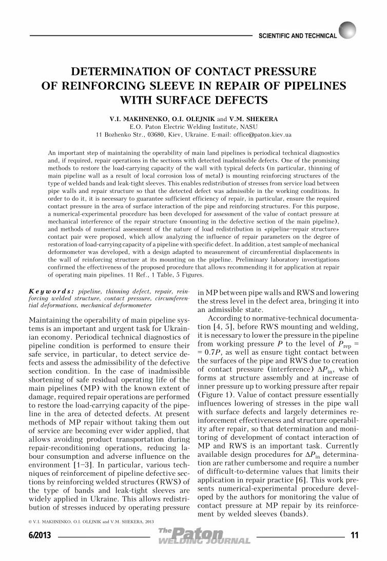
In the approximation of uniform distributionof contact between the surfaces of «pipeline—re-inforcing structure» contact pair working pres-sure in MP after mounting the repair structurecan be presented by the following dependence:
P = Pp + ΔPsl + ΔPin, (1)
where Pp, ΔPsl is the part of working load takenup by the pipeline and repair structure, respec-tively.
Work [7] gives graphic dependencies, whichcharacterize the degree of stress redistributionafter MP repair by reinforcement at ideal fit ofRWS to the pipeline. For this case part of pres-sure P, which will be taken up by RWS wall,can be described by the dependence
ΔPsl = (P — Prep)χ1, (2)
where χ1 = ⎛⎜⎝
⎜⎜1 +
(0.5Dsl)2 δ
(0.5D)2δsl
⎞⎟⎠
⎟⎟
—1
.
Formula (2) does not allow for contact pres-sure (ΔPin = 0) created during RWS mounting,welding of longitudinal welds and pressure in-crease up to working pressure. If at pressure inthe pipeline [P], pipe wall defects become ad-missible, then to ensure long-term operating re-liability of pipeline section with the mountedrepair structure the following condition shouldbe satisfied:
Pp ≤ [P]. (3)
Respectively, from (1)—(3) it follows that
P — (P — Prep)χ1 — ΔPin ≤ [P]. (4)
Hence, pressure in the pipeline Prep, at whichRWS should be mounted, is as follows:
Prep ≤ [P] — P(1 — χ1) + ΔPin
χ1 at ΔPin > 0. (5)
Thus, criterion for selection of the requiredcontact pressure value follows from (5)
ΔPin ≥ P — [P] — χ1(P — Prep). (6)
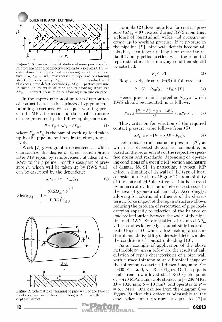
Determination of maximum pressure [P], atwhich the detected defects are admissible, isbased on the requirements of the respective speci-fied norms and standards, depending on operat-ing conditions of a specific MP section and natureof damage [8, 9]. In particular, a typical MPdefect is thinning of its wall of the type of localcorrosion at metal loss (Figure 2). Admissibilityof the state of MP defective section is assessedby numerical evaluation of reference stresses inthe area of geometrical anomaly. Accordingly,allowing for additional influence of the charac-teristic force impact of the repair structure allowsreducing the problem of restoration of pipe load-carrying capacity to selection of the balance ofload redistribution between the walls of the pipe-line and RWS. Substantiation of required ΔPinvalue requires knowledge of admissible linear de-fects (Figure 3), which allow making a conclu-sion about admissibility of detected defects underthe conditions of contact unloading [10].
As an example of application of the abovemethodology, given below are the results of cal-culation of repair characteristics of a pipe wallwith surface thinning of an ellipsoidal shape ofthe following geometrical dimensions, mm: S == 600, C = 550, a = 3.5 (Figure 4). The pipe ismade from low-alloyed steel X60 (yield pointσy = 420 MPa, admissible stresses [σ] = 286 MPa,D = 1020 mm, δ = 10 mm), and operates at P == 5.5 MPa. One can see from the diagram (seeFigure 3) that this defect is admissible in thecase, when inner pressure is equal to [P] ≈
Figure 1. Schematic of redistribution of inner pressure afterreinforcement of pipe defective section by a sleeve: D, Dsl –outer diameters of pipe and reinforcing structure, respec-tively; δ, δsl – wall thicknesses of pipe and reinforcingstructure, respectively; δmin – minimum residual wallthickness in the defect location; Pp, ΔPsl – parts of pressureP taken up by walls of pipe and reinforcing structure;ΔPin – contact pressure on reinforcing structure on pipe
Figure 2. Schematic of thinning of pipe wall of the type oflocal corrosion metal loss: S – length; C – width; a –depth of defect
12 6/2013

≈ 0.77P. The Table gives the results of calcula-tion of minimum required ΔPin, depending onRWS wall thickness δsl, made according to (6).
Calculation results lead to the conclusion thatto satisfy condition (3) it is possible to vary sleevewall thickness δsl and contact pressure ΔPin. Cor-rect determination of ΔPin, particularly for thecase of Prep → P, is the most significant for en-suring the operability of a section repaired usingthe sleeve. Interference at mounting RWS onpipeline defective section can be controlled usingthe method of experimental measurement of cir-cumferential displacements of RWS wall, due toelastic deformation at mechanical interference.In this case, ΔPin calculation in RWS wall isperformed by determination of Δl – variationof length l of the selected basic section of thestructure, as a result of interference, comparedto unloaded state and subsequent calculation bythe formula
ΔPin = Δll
E 2δsl
D + 2δsl
, (7)
where E is the steel modulus of elasticity.In order to follow Δl variation under field
conditions at repair-reconditioning operations onan operating pipeline, the currently operating
strain gauges and deformometers [11] were usedas a basis to develop a new modification of amechanical deformometer with base l ≈ 100 mm,the appearance and schematic of which are givenin Figure 5. The instrument allows measurementof circumferential deformations on cylindricalsurfaces of 380 mm and greater diameter by theresults of direct measurement of reciprocal mo-tion of a pair of depressions, made on the sleevesurface by punching.
Measurement principle consists in transfer-ring the displacements in the structure from con-tact points through reinforcing lever 1 with 1:5arm ratio to clock-type indicator 2. Transverserack 4 with two assemblies for magnetic pressing
Figure 3. Diagram of admissible linear dimensions of pipewall thinning Scr depending on minimum thickness of pipewall δmin for pipeline of 1020 × 10 mm size from X60 steelwith maximum service load P = 5.5 MPa at different innerpressures: 1 – 0.6P; 2 – 0.7P; 3 – 0.8P; 4 – P
Figure 4. Experimental facility with mechanical defor-mometer for contact pressure determination
Results of calculation of required ΔPin at repair of pipeline of1020 × 10 mm size from X60 steel with wall thinning of S == 600 mm, C = 550 mm, a = 3.5 mm
P, MPa [P] Prep δ, mm δsl, mm ΔPin
5.5 ~0.77P 0.7P 10 10 0.083P
15 0.054P
20 0.035P Figure 5. Appearance (a) and schematic (b) of mechanicaldeformometer: (for designations see the text)
6/2013 13

of the deformometer to RWS is fastened in themiddle part of base 3 for a stable fastening ofdeformometer to cylindrical surface. Each assem-bly located at rack end faces, consists of yoke 5with caulked-in magnet, governing screw 6 andsprings 7, balancing pressing-down. In the caseof insufficient pressing of the instrument to themetal, links 8 are provided on the band lowerhalf for deformometer fastening. The links allow,by placing circumferential safety straps on them,avoiding accidental disconnection and fallingdown of the instrument. Holding assembly(screw 9 with spring 10) is provided for fasteningof the rod and lever (instrument mounting andtransportation).
To ensure complete control of uniform clamp-ing of the pipe, several deformometers can beused, which are mounted in the characteristicpoints of the repair structure.
Preliminary laboratory testing of the defor-mometer in a special facility (see Figure 5) con-sisting of a pipe section from steel 09G2S of 377 ×× 11 mm size, 1000 mm length and 400 mm longband with 11 mm wall thickness, confirmed suf-ficient accuracy (approximately 1 μm) and effec-tiveness of the developed deformometer that al-lows recommending it for application in repair-restoration work in operating MP.
Conclusions
1. Numerical-experimental procedure was devel-oped to assess the contact pressure between pipe-line walls and RWS in terms of effectiveness ofrestoration of load-carrying capacity of pipelinewall with typical service defects. Numerical al-gorithm was proposed for assessment of load re-distribution at contract interaction of structuralelements and influence of reinforcement on ad-missibility of pipeline operation. The case of atypical thinning defect of the type of metal lossis used to show the essential influence of thevalue of RWS mechanical interference at itsmounting on repair effectiveness.
2. Pilot sample of mechanical deformometerwas developed with its design adapted to meas-urement of circumferential displacements in thewall of the reinforcing structure at its mountingon the pipeline. Proceeding from the results oflaboratory tests, it was established that the ac-curacy of measurement of displacements in thewall of the reinforcing structure using this de-formometer (approximately 1 μm) is sufficientfor assessment of the magnitude of mechanicalinterference and confirmation of the effectivenessof repair of defective sections of the pipeline.
1. La Morte, C.R., Boring, M., Porter, N. (2007) Ad-vanced welding repair and remediation methods forin-service pipelines: Final report. Columbus: EWI.
2. Kiefner, J.F. (1977) Repair of line pipe defects byfull-encirclement sleeves. Welding J., 6, 26—34.
3. Kiefner, J.F., Bruce, W.A., Stephens, D.R. (1994)Pipeline repair manual. Houston: Techn. Toolboxes.
4. VBN V.3.1-00013741-07:2007: Main oil pipelines.Methods of repair of defective sections. Introd.01.01.2007. Kiev: Ministry of Fuel and Energy ofUkraine.
5. GBN V.3.1-00013741-12:2011: Main gas pipelines.Repair by arc welding in service conditions. Introd.09.06.2011. Kiev: Ministry of Fuel and Energy ofUkraine.
6. Kryzhanivsky, E.I., Palijchuk, I.I. (2008) Method ofcalculation of contact pressure for sleeve and pipejoined with interference. Naftogaz. Energetyka, 1,78—82.
7. Makhnenko, V.I., But, V.S., Kozlitina, S.S. et al.(2010) Optimal reduction of working pressure inpipelines for repair of thinning regions by surfacing.The Paton Welding J., 10, 6—9.
8. DSTU-NBV.2.3.-21:2008: Directive. Determinationof residual strength of main pipelines with defects.Kyiv: Minregionbud Ukrainy.
9. (2000) Fitness-for-service. American Petroleum Insti-tute Recommended Practice 579. 1st ed.
10. Olejnik, O.I., But, V.S. (2010) Computational meth-ods in development of technologies of main pipelinerepair by welding under pressure. In: Proc. of 5thInt. Conf. on Mathematical Modelling and Informa-tion Technologies in Welding and Related Processes(25—28 May, 2010, Katsiveli, Ukraine). Kiev: PWI,177—182.
11. Kasatkin, B.S., Kudrin, A.B., Lobanov, L.M. et al.(1981) Experimental methods of study of strains andstresses. Kiev: Naukova Dumka.
Received 26.02.2013
14 6/2013

GASOABRASIVE WEAR RESISTANCEAT ELEVATED TEMPERATURES OF COATINGS
PRODUCED BY THERMAL SPRAYING
V.I. POKHMURSKY1, M.M. STUDENT1, A.V. POKHMURSKAYA2, I.A. RYABTSEV3,V.M. GVOZDETSKY1 and T.R. STUPNITSKY1
1H.V. Karpenko Physico-Mechanical Institute, NASU5 Nauchnaya Str., 79601, Lvov, Ukraine. E-mail: [email protected]
2Chemnitz University of Technology, Institute of Composite Materials and Surface Technology73 Erfenschlager Str., 09105, Chemnitz, Germany. E-mail: [email protected]
3E.O. Paton Electric Welding Institute, NASU11 Bozhenko Str., 03680, Kiev, Ukraine. E-mail: [email protected]
Thermal spraying is becoming ever wider accepted to produce reconditioning and protective coatings forvarious functional purposes. However, service life of such coatings has not been studied well-enough sofar. This work is a study of the mechanism of formation of electric arc sprayed coatings from flux-coredwires of Fe—Cr—B—Al alloying system. It is found that gasoabrasive wear resistance of coatings fromflux-cored wires depends on coating hardness, stresses of the first kind in the coating and on compositionof oxide films, which form at spraying and at elevated temperatures during gasoabrasive wear testing.Oxide films initially form on the drop surface during spraying. In addition, in air the porous electric arcsprayed coatings are found to have oxidation on the surface and inside the coating (interlamellar oxidation)and oxidation on the boundary between the coating and steel base. It is shown that the high resistance togasoabrasive wear is observed in coating, in which tensile stresses are transformed into compressive stressesas a result of the process of inner interlamellar oxidation during isothermal soaking at testing temperatureof 400—600 °C, leading to increase of coating volume and improvement of its cohesion strength as a resultof its reinforcement by interlamellar films of 100—150 nm thickness. Optimum content of alloying elementsand their influence on gasoabrasive wear resistance of coatings are determined. Positive influence of residualcompressive stresses in the coatings on gasoabrasive wear is shown. Proposed coatings will become appliedin power engineering enterprises. 13 Ref., 1 Table, 12 Figures.
Keywo r d s : thermal spraying, coatings, flux-coredwires, gasoabrasive wear
Electric spraying process is a sufficiently simpleand inexpensive one among thermal sprayingmethods [1]. Recent introduction of electrodesin the form of flux-cored wires (FCW) for ther-mal spraying enabled widening the field of ap-plication of this method and producing recondi-tioning and protective coatings for various func-tional purposes [2—5], in particular for protectionfrom corrosion and gasoabrasive wear of heatingelements of thermal electric power stations [6—12]. However, service life of such coatings hasnot yet been well enough studied that restrainswide-scale application of this method.
The paper is devoted to investigation of theinfluence of alloying elements on coating struc-ture, their mechanical characteristics, wear re-sistance at gasoabrasive wear and gas corrosionresistance at higher temperature.
Experimental procedure and studied materi-als. Coatings were applied by thermal spraying
with EM-14 metallizer, spraying FCW of 1.8 mmdiameter. Powders of boron-containing com-pounds (ferrochromium boron FKhB-2 and boroncarbide), pure metals (chromium, tungsten andaluminium), as well as aluminium-magnesium al-loys were used as charge components. DevelopedFCW were compared with those of foreign com-panies (Table), which are used for part protectionfrom gasoabrasive wear. Strip from steel 08kp(rimmed) of 0.4 mm thickness and 10 mm widthwas used as wire sheath. Coefficient of FCWfilling with the charge was 22—35 wt.%. Modesof coating deposition were as follows: I = 150—160 A, Ua = 32—34 V. FCW was sprayed by anair jet under the pressure of 0.60—0.65 MPa with140—150 mm spraying distance. Coating phasecomposition was studied in DRON-3 diffractome-ter with computer recording of diffractograms.CuKα-radiation was used at U = 32 V and I == 15 mA. Scanning step was 0.05.
Coating structure and chemical compositionafter spraying and oxidation were studied in theCarl Zeiss scanning microscope EVO-40 XVP
© V.I. POKHMURSKY, M.M. STUDENT, A.V. POKHMURSKAYA, I.A. RYABTSEV, V.M. GVOZDETSKY and T.R. STUPNITSKY, 2013
6/2013 15

with microanalysis system EVO-4XVP. Micro-hardness was determined in PMT-3 hardness meter.
In confidence interval of 0.95 and with mini-mum experiment number (four) relative error ofdetermination of cohesive and adhesive strength andwear resistance parameters did not exceed 5 %.
Samples of electric arc sprayed coating mate-rial for determination of the modulus of elasticityby the method of three-point bending were pre-pared as follows. One surface (of 100 × 20 mmsize) of 100 × 20 × 6 mm samples from steel 20was coated with tin 2 of 40—50 μm thickness andsubjected to jet treatment with corundum forpreparation of tinned surface for spraying.
Six samples were fastened on the forming sur-face of a hexagon and 1.5 mm coating from FCWwas deposited. Spray-deposited plates wereground from end faces and over the sprayed sidedown to coating thickness of 1 mm. Preparedsamples were placed into a heated furnace, wherethe temperature was 50 °C higher than tin meltingtemperature. At heating of coated steel platesthe tin layer melted and coating spalled sponta-neously due to internal stresses. As a result,beam-type samples of 100 × 20 × 1 mm size fromcoating material were made. Modulus of elastic-ity of electric arc sprayed coatings was deter-mined by bending method, and calculation wasperformed as follows [13]:
E = Lv
3(P2 — P1)
4bh3(Z2 — Z1),
where Lv is the distance between base cutters,mm; P1, P2 is the magnitude of first and secondload, g; b is the plate width, mm; h is the platethickness, mm; Z1, Z2 are the indicator readingsat the first and second loading, mm.
Investigation of gasoabrasive wear at elevatedtemperatures (up to 600 °C) was conducted in alaboratory unit with application of mechanicalacceleration of abrasive (in particular, quartz
sand < 200 μm) with particle velocity of 10—40 m/s, and 30° angle of incidence.
Figure 1 gives the schematic of a unit for test-ing coatings for gasoabrasive wear at higher tem-perature.
The unit consists of electric furnace 1 (tem-perature is regulated with accuracy of ±2 °C),abrasive feeding device 2, DC electric motor 3,module of adjustment of engine revolutions 4.To eliminate the edge effects resulting from coat-ing tearing off by abrasive jet on sample edges,they were tightly fastened to each other on theinner side of ring 5 (Figure 1, a).
Assembly of abrasive feeding and acceleration(Figure 1, b, c) consists of inner pipe fixed rig-idly, through which the abrasive is uniformlysupplied to abrasive acceleration assembly. Ex-ternal pipe, which is fixed on bearings in thecase, is designed to transfer the torque to abrasiveacceleration assembly. Bearings are air-cooled.
Samples were made from steel 12Kh1MF of20 × 40 × 6 mm size, and 10 μm of nickel wasdeposited on all the sample surfaces by galvaniz-ing to eliminate the uncontrolled increase of sam-ple weight, because of oxidation of their un-sprayed surfaces at elevated temperatures. Nickellayer was removed by machining from one sideof the sample (20 × 40 mm). This surface wassubjected to corundum jet treatment and electricarc coating of 1000 μm thickness was depositedlayer-by-layer in six passes.
Sprayed surface of samples was ground to700 μm thickness. Experimental investigationswere conducted at 30° angle of abrasive attackand abrasive velocity of 36 m/s, which was setby varying the speed of revolution of DC electricmotor 3 from adjustment module 4 (see Figure 1,a). Wear resistance of coated samples was deter-mined by their weight loss with up to 0.0002 gaccuracy.
Experimental results and their discussion.Influence of FCW charge composition on coating
Calculated FCW composition, wt.%
FCW grade B Cr Al W Mo Si Other Fe Wire trade mark
PP-Kh6R3Yu2 3 6 2 — — — — Base FMI
PP-Kh6R3Yu6 3 6 6 — — — — Same FMI-2
PP-Kh6R3Yu14 3 6 14 — — — — » FMI-11
PP-70Kh6R3Yu6 3 6 6 — — — — » FMI
ПП-70V6R3Yu6 3 — 6 — — — — » FMI-7
PP-500Kh20R5M10V10B10G5S2
5 20 — 10 10 2 10Nb » EndoTec DO 390N
PP-Kh30M15Yu4 — 22 5 — — — — » EuTronic Arc 509
PP-Kh29R4S2G2 4 29 — — — 2 2Mn » Praxair and TAFA 95MXC
16 6/2013

structure. To study the composition of the dropsformed at FCW spraying by an air jet, they weretrapped in a snow target, and the cuts on sectionswere studied. It is established that minimum dropsize was 15 μm, and maximum was 400 μm. Frac-tion of 18—50 μm size amounted to 50 wt.%, 50—150 μm size to 40 wt.%, and amount of dropslarger than 150 μm was small at 10 wt.%. Duringspraying of FCW of Fe—Cr—B—Al alloying sys-tem, the charge and sheath do not have enoughtime to fuse completely because of the transiencyof melting processes, so that a heterogeneous meltand drops of three types form:
• drops of metal melt, based on Fe alloyedwith 3—5 % Cr, 6—14 % Al and B, are surroundedby Al2O3 oxide, the particles of which grow asround islets on drop periphery (Figure 2, a);
• drops of metal melt, based on Fe alloyedwith 3—5 % Cr, 2—4 % Al and B, are surrounded
by an oxide film (FeCr)2O3, which is locatedbetween ferrochrome dendrites (Figure 2, b);
• round drops of pure oxide Al2O3(FeAlCr)2O3 and (FeCr)2O3 (Figure 2, c).
When hitting the spraying surface, moltendrops are badly deformed and solidify in layersas lamels, separated by oxide films (Figure 3,a). Phase analysis of electric arc sprayed coatingsrevealed that at formation of coatings using FCWwith B4C + Fe charge, coating matrix phase isFeα with inclusions of Fe3C ferric carbide andfree B (Figure 3, b, c). In this case, interactionof boron carbide with iron melt at spray-deposi-tion of coatings runs by the following reaction:Fe + 1/3B4C = 1/3Fe3C + 4/3B. Adding Cr-containing elements to FCW charge promotesdisappearance of free B in the coating structure,whereas interaction of boron carbide with Cr pro-ceeds by the following reaction: Cr + 2/7B4C == 4/7CrB2 + 1/7Cr3C2.
Figure 1. Schematic of unit for gasoabrasive wear testing of coatings at elevated temperature (a), and assemblies forabrasive feeding (b) and acceleration (c) (for designations see the text)
Figure 2. Structure and composition of drops sprayed from FCW on snow target: a—c – see the text
6/2013 17

Coating structure at elevated temperatures.Unlike solid materials in porous electric arcsprayed coatings oxidation in air at elevated tem-peratures occu both on coating surface and insideit (interlamellar oxidation) (Figure 4, a, b). Inaddition, oxidation occurs on the boundary be-tween the coating and steel base (Figure 4, c).As a result of 8—10 % porosity of the coatingsoxygen penetrates into the steel base even at coat-ing thickness of 0.5—0.8 μm. Total oxygen con-tent in the initial coating is equal to 2.5—3.0 wt.%. After soaking for 100 h at 550 °C oxy-gen content in the coating rises up to 4—5 wt.%,at 100 h soaking at 700 °C – up to 8.0—9.5 wt.%.Here coating oxidation rate is 10—30 times lowerthan that of steel.
At the temperature of 600—700 °C oxide filmsof hematite Fe2O3 form on steel surface, growingin the form of needle-like projections 100—200 nm thick (Figure 5, a). On coatings withnot more than 2 % Al (PP-Kh6R3Yu2) oxidefilms of hematite alloyed by chromium and alu-minium (FeCr)2O3 are formed, growing on thesurface in the form of strobiloidal protrusions of5—10 μm thickness (Figure 5, b). Oxide films ofhematite alloyed by aluminium (FeAl)2O3 formon Kh6R3Yu6 and Kh6R3Yu14 coatings withhigher aluminium content, which grow on thesurface in the form of monolithic film (Figure 5,
c). Oxide films 0.2—2.0 μm thick form betweencoating lamels. These films contain particles ofmatrix metal phase 100—300 μm long, stronglybonded to matrix phase (Figure 5, d).
Two-layer oxide film forms on the boundarybetween coating and base. The part adjacent tothe coating has an increased content of alu-minium, and the part adjacent to the base hashigher iron. Oxide film is embedded into thecoating as though by anchors, and strongly bindsit to the steel base.
Influence of testing temperature on coatingmechanical characteristics. During long-termsoaking at testing temperature of 600 °C, hard-ness of all the coatings decreases and is stabilizedon the level of HV 500—550, because of coarsen-ing of strengthening phase – FeCr2B borides.So, as shown by metallographic analysis, afterspraying boride size does not exceed 100 nm, andafter soaking for 5000 h at 600 °C, their sizeincreases to 300—500 nm (Figure 6, a, b). Long-term soaking of coatings at testing temperatureof 600 °C promotes increase of their cohesionstrength (Figure 7).
Such an effect is predetermined by reinforce-ment of coating structure by thin (less than1 μm) oxide films (see Figure 5, d). Here, thecoating acquires a composite structure. The great-est strengthening is observed for a coating from
Figure 3. Structure of electric arc sprayed coatings: a – FCW with (FeCr)2B + Fe charge; b – FCW with B4C + Fecharge; c – same, boron inclusions in the coating
Figure 4. Coating structure after soaking at 600 °C for 2000 h: a – total coating structure (1 – base (12Kh1MF steel);2 – coating; 3 – oxide film on coating surface); b – transition zone between coating and oxide film on coating surface;c – transition zone between coating and base metal
18 6/2013

FCW Kh6R3Yu14, that is related to coating re-inforcement by aluminium oxide films.
Modulus of elasticity of spray-deposited coat-ings without heat treatment is in the range of50,000—70,000 MPa. At increase of testing tem-perature above 350 °C, the modulus of elasticityof FCW 70V6R3Yu6 coating rises almost 3 times,and for a coating from FCW Kh6R3Yu14 – by70 % (Figure 8, a) [13]. Increase of modulus ofelasticity is determined by inner interlamellaroxidation and it is directly proportional to theamount of oxide phase in the coating. So, themodulus of elasticity of 70V6R3Yu6 coating afterspraying is equal to 52,000 MPa, and oxide phaseamount is 4 wt.%; after soaking for 100 h at600 °C the value of the modulus of elasticity risesup to 180,000 MPa, and amount of interlamellaroxide phase is 14 wt.% (Figure 8, b).
Long-term exposure of samples at the tem-perature of 600 °C also leads to an essential de-crease of tensile stresses in the coating. Two time
Figure 5. Structure of surface films: a—c – see the photoars; d – lamels
Figure 6. Structure of coatings with borides after spraying (a) and after soaking at 600 °C for 5000 h (b)
Figure 7. Influence of soaking at 600 °C for 1000 h oncohesion strength of coatings: 1 – initial; 2 – soaking
6/2013 19

stages and two mechanisms are determined, bywhich lowering of tensile stresses in the coatingproceeds (Figure 9).
So, at the first stage which lasts up to 20 h at600 °C stress lowering occurs due to decompositionof austenite in the coating structure, that is accom-panied by increase of coating volume. At the secondstage with increase of soaking time above 20 h,compressive stresses rise, because of running of justthe process of intralamellar oxidation of the coating
and increase of the amount of oxide phase, thatessentially increases the coating volume.
Gasoabrasive wear resistance of electric arcsprayed coatings. With increase of boron contentin the coating up to 2.5 wt.%, gasoabrasive wearresistance of coatings becomes higher. Increasedcontent of boron in the coatings above 2.5 wt.%leads to increase of tensile stresses in the coatingand appearance of a net of microcracks in it, thatlower coating wear resistance. As the same time,with increase of aluminium content in FCW with2.5 wt.% B, gasoabrasive wear resistance of coat-ings rises monotonically (Figure 10, a). Replace-ment of FKhB master alloy by B4C in FCWcharge only slightly, by 15 %, lowers the wearresistance, so that these components can be irre-placeable (Figure 10, b).
Investigations for gasoabrasive wear resis-tance of coatings from FCW with varying contentof aluminium of 2, 6, 14 wt.% showed that below350 °C gasoabrasive wear resistance of coatingsand steel rises only slightly (Figure 11), but atlowering of aluminium content in FCW coatingwear resistance becomes significantly lower thanthat of steel.
This is related to the fact that at spraying ofcoatings from FCW with a low content of alu-minium they develop considerable tensilestresses, relaxation of which occurs through for-mation of a net of microcracks. With increase ofaluminium content, a more heterogeneous coat-ing forms, and much lower tensile stresses de-velop, due to their relaxation by plastic defor-
Figure 8. Temperature influence on oxidation intensity (1) and modulus of elasticity (2) of coatings (a), and of amountof interlamellar oxides in the coating on modulus of elasticity (b)
Figure 9. Influence of soaking at 600 °C on stress level incoatings: 1 – first; 2 – second time stage
20 6/2013
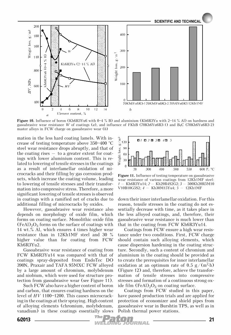
mation in the less hard coating lamels. With in-crease of testing temperature above 350—400 °Csteel wear resistance drops abruptly, and that ofthe coating rises – to a greater extent for coat-ings with lower aluminium content. This is re-lated to lowering of tensile stresses in the coatingsas a result of interlamellar oxidation of mi-crocracks and their filling by gas corrosion prod-ucts, which increase the coating volume, leadingto lowering of tensile stresses and their transfor-mation into compressive stress. Therefore, a moresignificant lowering of tensile stresses is observedin coatings with a ramified net of cracks due toadditional filling of microcracks by oxides.
However, gasoabrasive wear resistance alsodepends on morphology of oxide film, whichforms on coating surface. Monolithic oxide film(FeAl)2O3 forms on the surface of coatings with14 wt.% Al, which ensures 4 times higher wearresistance than in 12Kh1MF steel and 30 %higher value than for coating from FCWKh6R3Yu2.
Gasoabrasive wear resistance of coating fromFCW Kh6R3Yu14 was compared with that ofcoatings spray-deposited from EndoTec DO390N, Praxair and TAFA 95MXC FCW alloyedby a large amount of chromium, molybdenumand niobium, which were used for structure pro-tection from gasoabrasive wear (see Figure 11).
Such FCW also have a higher content of boronand carbon, that ensures coating hardness on thelevel of HV 1100—1200. This causes microcrack-ing in the coatings at their spraying. High contentof alloying elements (chromium, molybdenum,vanadium) in these coatings essentially slows
down their inner interlamellar oxidation. For thisreason, tensile stresses in the coating do not es-sentially decrease with time, as it takes place inthe less alloyed coatings, and, therefore, theirgasoabrasive wear resistance is much lower thanthat in the coating from FCW Kh6R3Yu14.
Coatings from FCW ensure a high wear resis-tance under two conditions. First, FCW chargeshould contain such alloying elements, whichcause dispersion hardening in the coating struc-ture. Secondly, such a content of chromium andaluminium in the coating should be provided asto create the prerequisites for inner interlamellaroxidation at an optimum rate of 0.5 g/(m2⋅h)(Figure 12) and, therefore, achieve the transfor-mation of tensile stresses into compressivestresses and formation of a continuous strong ox-ide film (FeAl)2O3 on coating surface.
Coatings from FCW studied in this paper,have passed production trials and are applied forprotection of economizer and shield pipes fromgasoabrasive wear in Burshtin TPS, as well as inPolish thermal power stations.
Figure 10. Influence of boron (Kh6R3Yu6 with 0—4 % B) and aluminium (Kh6R3Yu with 2—14 % Al) on hardness andgasoabrasive wear resistance W of coatings (a), and influence of FKhB (70Kh6Yu6R3-1) and B4C (70Kh6Yu6R3-2)master alloys in FCW charge on gasoabrasive wear (b)
Figure 11. Influence of testing temperature on gasoabrasivewear resistance of various coatings from 12Kh1MF steel:1 – Kh6R3Yu14; 2 – Kh29R4S2G2; 3 – 500Kh20R5M10V10B10G5S2; 4 – Kh30M15Yu4; 5 – 12Kh1MF
6/2013 21

Conclusions
1. Procedure of investigation of gasoabrasvie wearof coatings was improved. It simulates the opera-tion of TPS boilers as close as possible, allowseliminating edge effects, which arise as a result ofcoating tearing off on the edges of samples by anabrasive jet, and avoiding uncontrolled incrementof sample mass due to oxidation of their non-sprayed surfaces at elevated temperatures.
2. To determine the modulus of elasticity of thecoating by three-point bending method, a proce-dure of making beam samples from uncoated ma-terial without a substrate was proposed. Depend-ence of variation of modulus of elasticity of electricarc sprayed coatings of Fe—Cr—B—Al system ontemperature and soaking time was established. Itis shown that the modulus of elasticity of the coat-ings is directly proportional to the amount of oxidephase, formed under the conditions of long-termsoaking at elevated temperatures.
3. It is also shown that gasoabrasive wearresistance of coatings from FCW depends on coat-ing hardness, stresses of the first kind in thecoating and on the type of oxide film, whichforms at elevated temperature during testing.
4. High resistance to gasoabrasive wear is dem-onstrated by coatings, in which tensile stressesare transformed into compressive stresses as aresult of the process of inner interlamellar oxi-dation during isothermal soaking at testing tem-peratures of 400—600 °C, that leads to increase
of coating volume, and of its cohesion strengthas a result of its reinforcement by interlamellarfilms of 100—150 nm thickness.
5. A connection between the morphology ofsurface oxide films and coating gasoabrasive wearresistance is established and it is found that highresistance to gasoabrasive wear is demonstratedby coatings, forming a dense film of iron oxidealloyed by aluminium.
6. A new composition of FCW Kh6R3Yu14was developed for deposition of high-temperaturecoatings capable of dispersion strengthening inoperation and improving the wear resistance of12Kh1MF steel 12 to 14 times, and its gasoabra-sive wear resistance by 2.5—4 times.
Figure 12. Influence of gas corrosion rate on gasoabrasivewear resistance of coatings and 12Kh1MF steel (testingtemperature of 600 °C)
1. Korobov, Yu.S., Lukanin, V.L., Pryadko, A.S. et al.(2002) Advantage of activated arc metallizing. Svar-shchik, 2, 16—17.
2. Borisova, A.L., Mits, I.V., Kajda, T.V. et al. (1991)Structure and properties of electric-arc sprayed ferro-boron-based coatings obtained from flux-cored wires.Avtomatich. Svarka, 9, 66—68.
3. Borisov, Yu.S., Korzhik, V.N. (1995) Amorphousthermal spray coatings: Theory and practice. Ibid., 4,3—12.
4. Borisov, Yu.S., Koziakov, I.A., Korzhik, V.N. (1996)Structure and properties of thermal spray coatingsmade using flux-cored wires of Fe—Cr—B, Fe—Cr—B—Csystem. Ibid., 5, 21—24.
5. Pokhmursky, V.I., Student, M.M., Dovgunyk, V.M.et al. (2005) Reconditioning and protective electric-arc sprayed coatings. Lviv: H.V. Karpenka PhMI.
6. Pokhmurska, H., Wielage, B., Grund, T. et al. (2008)Arc-sprayed coatings obtained from iron based coredwires under high-temperature abrasive wear conditions.In: Proc. of Int. Thermal Spray Conf., 338—341.
7. Student, M.M., Pokhmurska, H.V., Hvozdetskyi,V.V. et al. (2009) Effect of high-temperature corrosi-on on the gas-abrasive resistance of electric-arc coa-tings. Materials Sci., 45(4), 481—489.
8. Dallaire, C.S., Levert, H., Legoux, J.-G. (2001) Erosi-on resistance of arc-sprayed coatings to iron ore at 25and 315 °C. J. Thermal Spray Techn., 10, 337—350.
9. Branagan, D.J., Swank, W.D., Haggard, D.C. et al.(2001) Wear resistant amorphous and nanocompositesteel coatings. Met. and Mater. Trans. A, 32(10),2615—2621.
10. Branagan, D.J., Alman, D.E., Newrick, J.W. (2001)Devitrified nanocomposite steel powder. In: Powdermetallurgy alloys and particulate materials for in-dustrial application. Warrendale, PA: Minerals, Me-tals and Mater. Soc., 111—122.
11. Branagan, D.J., Tang, Y. (2002) Developing extremehardness (>15 GPa) in iron-based nanocomposites.Composites, 6, 855—859.
12. Badish, E., Katsich, C., Winkelmann, H. et al. (2010)Wear behaviour of hardfaced Fe—Cr—C alloy and auste-nitic steel under 2-body and 3-body conditions at eleva-ted temperature. Tribology Int., 2, 214—228.
13. Babichev, M.A. (1955) Methods for determination ofinternal stresses in machine parts. Moscow: ANSSSR.
Received 24.01.2013
22 6/2013
APPLICATION OF INDUCTION HEAT TREATMENTTO PROVIDE CORROSION RESISTANCEOF STAINLESS STEEL WELDED PIPES
E.A. PANTELEJMONOV and L.I. NYRKOVAE.O. Paton Electric Welding Institute, NASU
11 Bozhenko Str., 03680, Kiev, Ukraine. E-mail: [email protected]
The effect of induction heat treatment using currents with a frequency of 2.4 kHz on corrosion resistanceof ∅85.6 × 0.6 and 142.9 × 0.9 mm welded pipes, made from chrome-nickel stainless steel 1.4301, at differentproportions of heat treatment temperatures, heating rate, time of holding at the heat treatment temperatureand cooling conditions was investigated. The use was made of specimens of the pipes after heating insingle-turn inductors, as well as specimens of the long pipes that passed under current the entire length ofthe through-type multiple-turn inductors. The heat treatment parameters were chosen on the basis of theirpossible implementation in lines for production of thin-walled welded pipes at welding speeds of up to0.063 m/s. It was shown that the heat treatment of the welded pipes in a temperature range of 700—770 °C,at heating rates of up to 47.7 °C/s and cooling rates of up to 12.5 °C/s leads to improvement of theircorrosion cracking resistance, and does not deteriorate their intercrystalline and pitting corrosion resistance.10 Ref., 1 Table, 4 Figures.
Keywo r d s : welded pipes, corrosion-resistant steel,heat treatment of pipes, corrosion cracking
Small- and medium-diameter welded pipes madefrom corrosion-resistant steels of the austeniticgrade are widely applied in oil and gas industries,as well as in heating and water supply systems.The low content of carbon in the steels decreasestheir sensitivity to pitting corrosion (PC) andintercrystalline corrosion (ICC) under the effectof environment [1]. The steels are characterisedby satisfactory values of strength and toughness,and by good weldability. However, the techno-logical operations of forming of an initial stripinto a tubular billet, local heating of edges in weld-ing and application of stiffeners, which are char-acteristic of production of welded pipes, lead to achange in structure and properties of the pipe met-al. Formation of ferritic and martensitic phases, inaddition to austenite, causes the probability of ICCor stress corrosion cracking (CC) [2].
Heat treatment (HT) is applied to providemaximal toughness and corrosion resistance, andto eliminate physical heterogeneity of pipes. Thepipes are heated in furnaces with a controlledatmosphere, or in a conventional atmosphere fol-lowed by removal of scale. In particular, heatingof the 08Kh18N10 steel pipes in a temperaturerange of 750—900 °C at a low holding and reduc-tion of the heating time does not lead to a markedimprovement of the CC resistance [3, 4]. At thesame time, to achieve the highest resistance of
pipes to ICC it is necessary to avoid the tempera-ture of the beginning of intensive oxidation ofsteel. For steel 08Kh18N10 this temperature is800—870 °C [5].
The time of heating of the pipes can be reducedby using the technology for induction heatingwith high-frequency currents. Generation of en-ergy directly into the pipe metal provides a highheating rate in a range of the phase transforma-tion temperatures that prevent growth of theaustenite grain. Conditions for elimination ofheterogeneity of volumetric changes can be cre-ated at an optimal proportion of the current fre-quency and pipe wall thickness. One of the ad-vantages of the technology is the possibility ofimplementing it by the continuous-sequentialmethod in welded pipe production lines [6—8].A thin layer of oxides forming on the pipe surfacesat high heating rates can be readily removed. Theinduction equipment and automation means al-low the specified HT parameters to be maintainedat a high accuracy.
This study was performed to investigate theeffect of induction HT using the 2.4 kHz fre-quency currents on corrosion resistance of weldedpipes measuring ∅85.6 × 0.6 and 142.9 ×× 0.9 mm, made from chrome-nickel stainlesssteel 1.4301. The efficiency of HT was estimatedfrom the results of tests of the pipe specimens tothe sensitivity to CC, ICC and PC.
Steel 1.4301, which is a close analogue of steel08Kh18N10, belongs to non-ferromagnetic mate-rials with relative magnetic permeability μ = 1.© E.A. PANTELEJMONOV and L.I. NYRKOVA, 2013
6/2013 23

The recommended current frequency for throughheating of hollow cylindrical billets with an ex-ternal diameter of up to 150 mm and wall thick-ness of up to 1 mm, made from the materials withμ = 1, ranges from 0.5 to 8.0 kHz [9, 10]. At acurrent frequency of 2.4 kHz the depth of pene-tration of the current into the steel exceeds thepipe wall thickness. It can be assumed that thepower through the pipe wall thickness is distrib-uted uniformly, this leading to decrease in inter-nal stresses.
Investigated were the pipe specimens afterheating in single-turn inductors, as well as thespecimens of long pipes that passed under thecurrent along the entire length of through-typemultiple-turn inductors. The frequency converterwith a power of 160 kW and a rated frequencyof 2.4 kHz, fitted with the transformer circuitfor matching the converter with a load, was usedas an induction heating source. Characteristicsof the inductors and ranges of variations in pa-rameters of HT of the pipe specimens are givenin the Table. The effect of the HT temperaturein a range of 440—750 °C, heating rate, time ofholding at the HT temperature, cooling condi-tions and speed of movement of the pipes in the
through-type inductors was evaluated. The work-ing frequency of the heating source ranged from1.95 to 2.30 kHz. Parameters of HT of the pipespecimens in the single-turn inductors, which areindicated in the Table, allow evaluating the ex-pected parameters of HT of the long pipes in thethrough-type inductors. In particular, at a tem-perature of 750 °C, through-type inductor lengthof 1 m and heating rates of 18.5—47.5 °C/s theexpected speed of the ∅85.6 × 0.6 and 142.9 ×× 0.9 mm pipes in the through-type inductorswill be 1.6—3.8 and 1.5—2.6 m/min, respectively.
Complex resistance of the single-turn induc-tors changes only insignificantly in heating ofshort specimens in these inductors. Some differ-ence was observed in the dynamics of heating ofspecimens in the single-turn and through-typeinductors. After the heating source reaches thespecified power, the rate of heating of a specimenin the single-turn inductor remained unchangedduring the entire heating time (Figure 1). Achange in the heating rate was achieved by chang-ing the specified power of the heating source.After switching off of the heating source uponreaching the HT temperature the time of naturalholding of the specimens at the HT temperature
Characteristics of inductors and ranges of variations in parameters of HT of pipe specimens
Type of inductor ParameterPipe size, mm
∅85.6 × 0.6 ∅142.9 × 0.9
Single-turn Length of current conductor, mm 95 120
Diameter of current conductor (internal), mm 100 160
Current frequency, kHz 2.1—2.3 2.0—2.2
Transformation coefficient of matching transformer 22/1 22/1
Compensating capacity, μF 85.6 116.0
HT temperature, °C 440—950 500—1150
Heating rate, °C/s 20.0—47.5 18.5—32.8
Cooling rate, °C/s 1.75—4.81 1.54—12.50
Holding at HT temperature, s 0—60 0—60
Speed of pipes (expected), m/s 0.026—0.063 0.025—0.043
Through-type multiple-turn Length of current conductor, mm 640 620
Diameter of current conductor (internal), mm 120 170
Quantity of current conductor turns 22 21
Current frequency, kHz 1.95—2.10 1.92—2.05
Transformation coefficient of matching transformer 13/4 13/4
Compensating capacity, μF 66.0 52.3
HT temperature, °C 540—850 500—780
Heating rate, °C/s 7.2—10.0 8.1—11.3
Cooling rate, °C/s 1.59—3.90 1.2—4.8
Holding at HT temperature, s 10—20 15—20
Speed of pipes (expected), m/s 0.0092 0.0083—0.014
24 6/2013

did not exceed 3—5 s. Adjustment of the powerof the heating source was applied to form a longerholding. In heating of the long pipes at theirconstant movement speed, the rate of heating ofthe specimens increased as they moved in thethrough-type inductors. A change in the HT tem-perature was achieved by changing the propor-tion of the pipe movement speed and power ofthe heating source. After the pipe specimens leftthe inductor-affected zone, the time of naturalholding at the HT temperature amounted to 20 s.Forced air cooling of the pipes (fan productivityof 2700 m3/h) at the exit of the through-typeinductors was used to reduce the holding time.In particular, when heating the ∅85.6 ×× 0.6 mm pipe to a temperature of 650—660 °Cat their speed of 0.0092 m/s, the forced air cool-ing of the pipes led to reduction of the holdingtime from 20 to 10 s.
The CC resistance tests of the pipes were car-ried out in compliance with requirements ofGOST 26294—84 «Welded Joints. CorrosionCracking Test Methods». The pipe specimens inthe initial state and after HT were held in 42 %solution of MgCl2 at a boiling temperature of154 °C. Formation of corrosion cracks waschecked every 4—5 h. The CC resistance criterionwas the time to formation of the first corrosioncrack.
No corrosion cracks formed during the testtime of 80 h after HT in the single-turn inductor(Figure 2) of the ∅85.6 × 0.6 mm pipe specimensat a temperature of 770—1070 °C, heating rate of41.0—56.3 °C/s and natural cooling rate of 3.91—4.96 °C/s. The corrosion cracks appeared 10—66 h after HT of the pipe specimens in a tem-perature range of 440—640 °C at a heating rateof 20.0—39.2 °C/s, without holding, and at anatural cooling rate of 1.75—2.83 °C/s. No cor-rosion cracks were detected on the ∅142.9 ×× 0.9 mm pipe specimens at the following HTparameters:
• 650—1100 °C temperature, 7.1—27.7 °C/sheating rate, without holding, 2.3—6.6 °C/snatural cooling rate;
• 1000 °C temperature, 6.4 °C/s heating rate,without holding, 9.3—12.5 °C/s forced air cool-ing rate;
• 960—1050 °C temperature, 6.7 and 29.1 °C/sheating rate, holding for 60 s, 5.36—5.50 °C/snatural cooling rate;
• 1100—1150 °C temperature, 7.1 and32.8 °C/s heating rate, holding for 60 s, 10.7—12.1 °C/s forced air cooling rate.
It should be noted that no corrosion crackswere detected on the ∅142.9 × 0.9 mm pipe speci-
mens at the heating rates varied within 6.4—7.1and 18.5—32.8 °C/s, temperature of 960—1150 °C, cooling rates of 2.3—12.5 °C/s and hold-ing for 60 s under the natural or forced air coolingconditions. Parameters of HT of such pipes inthe single-turn inductors (960—1000 °C tempera-ture, 23.8—29.1 °C/s heating rate, 5.18—5.50 °C/s natural cooling rate) corresponded toparameters of HT of the long pipes, 650 mm long,in the through-type inductors at their speed ofabout 0.025 m/s.
The corrosion cracks formed on the ∅142.9 ×× 0.9 mm pipe specimens (see Figure 2) 10—66 hafter HT in a temperature range of 500—600 °C,at heating rates of 21.7—25.0 °C/s, without hold-ing, and at natural cooling rates of 1.54—2 °C/s.
Figure 2. Dependence of time to formation of corrosioncracks on temperature of HT of the ∅85.6 × 0.6 (a) and142.9 × 0.9 (b) mm pipe specimens heated in single-turninductors: 1 – presence of cracks; 2 – absence of cracks
Figure 1. Dynamics of variations in temperature of pipespecimens during heating in single-turn (1) and through-type (2) inductors
6/2013 25

On the ∅85.6 × 0.6 and 142.9 × 0.9 mm pipespecimens, which were not subjected to HT, thecorrosion cracks appeared after 5 and 4 h, respec-tively. Therefore, the minimal temperature of HTof the ∅85.6 × 0.6 and 142.9 × 0.9 mm pipespecimens after heating in the single-turn induc-tors, above which no corrosion cracks formed, is770 and 650 °C, respectively.
On the ∅85.6 × 0.6 mm, long pipe specimensthe corrosion cracks formed 24 h after HT in thethrough-type inductor at a temperature of540 °C, heating rate of 7.2 °C/s, natural coolingrate of 1.85 °C/s, and speed of 0.0092 m/s (Fi-gure 3). The corrosion cracks did not form afterHT at a temperature above 650 °C. On the∅142.9 × 0.9 mm, long pipe specimens the cor-rosion cracks formed 15—30 h after HT at tem-peratures of 500 and 610 °C, heating rates of 8.7and 8.1 °C/s, forced air cooling rates of 1.2 and2.7 °C/s, and speed of 0.014 m/s. As a rule, acrack initiated at the absence of pitting. There-fore, the corrosion cracks did not form after heat-ing of the ∅142.9 × 0.9 mm, long pipe specimensabove 650 °C.
The tests to ICC were carried out accordingto GOST 6032—89 «Corrosion-Resistant Steelsand Alloys. Intercrystalline Corrosion Resistance
Test Methods» (item 3). The ICC resistance cri-terion was the absence of fracture at the grainboundaries to a depth of more than 10 μm. Thepipe specimens were held in a boiling aqueoussolution of 13 % CuSO4 + 12 % H2SO4 at thepresence of metal copper. The time of holdingwas 24 ± 0.25 h. No fractures along the grainboundaries were detected on the pipe specimensboth in the base metal and in the weld zone afterHT in the single-turn and through-type induc-tors. This is indicative of the ICC resistance ofthe pipe specimens.
The PC resistance tests of the pipe specimenswere carried out in compliance with requirementsof GOST 9.912—89 «Corrosion-Resistant Steelsand Alloys. Accelerated Pitting Corrosion Resis-tance Test Methods». Allowing for the total lossof weight of three identical pipe specimens afterholding in the 10 % solution of FeCl3 for 24 h,the conditional average rate of PC of the pipespecimens not subjected to HT was v == 10 g/(m2⋅h) (Figure 4). Pittings propagatedin the base metal. Isolated pittings had a throughcharacter. The welds contained isolated part-through pittings. The pipe specimens after HTin the single-turn and through-type inductors ata temperature of up to 780 °C had v = 5.2—9.8 g/(m2⋅h). The quantity of pittings on thebase metal and in the weld decreased. Mostly
Figure 3. Dependence of time to formation of corrosioncracks on temperature of HT of the ∅85.6 × 0.6 (a) and142.9 × 0.9 (b) mm long pipe specimens heated in through-type inductors: 1 – presence of cracks; 2 – absence ofcracks
Figure 4. Effect of HT temperature on conditional averagerate of PC of the ∅85.6 × 0.6 (a) and 142.9 × 0.9 (b) mmpipe specimens
26 6/2013

the weld experienced PC. It can be consideredthat HT did not deteriorate the PC resistance ofthe investigated pipe specimens.
Conclusions
1. HT of welded pipes with a diameter of up to150 mm and wall thickness of up to 1 mm, madefrom chrome-nickel stainless steel 1.4301, in atemperature range of 700—770 °C, at heating ratesof up to 47.7 °C/s, cooling rates of up to12.5 °C/s, and speed of movement of up to0.063 m/s leads to increase in CC resistance ofthe pipes, and does not deteriorate their ICC andPC resistance.
2. It is recommended to use induction heatingwith the 2.4 kHz frequency currents to conductHT of thin-walled pipes from corrosion-resistantsteels in lines for production of pipes by the ar-gon-arc, electron beam and laser welding meth-ods.
1. Semzin, V.N., Shron, R.Z. (1978) Heat treatmentand properties of welded joints. Leningrad: Mashi-nostroenie.
2. Gulyaev, G.I., Vojtselenok, S.L. (1978) Quality ofwelded pipes. Moscow: Metallurgiya.
3. Sokol, I.Ya., Ulianin, E.A., Feldgandler, E.G. et al.(1989) Structure and corrosion of metals and alloys:Refer. Book-Atlas. Moscow: Metallurgiya.
4. Gulyaev, A.P. (1963) Metals science. Moscow:Oborongiz.
5. Borodulin, G.M., Moshkevich, E.I. (1973) Stainlesssteel. Moscow: Metallurgiya.
6. Krotkova, O.V., Chervinsky, V.I., Ratnikova, A.I. etal. (2010) Development of technology and equipmentfor induction heat treatment of corrugated stainlesssteel pipes. Indukts. Nagrev, 3, 27—34.
7. Golovin, G.F., Zimin, N.V. (1979) Technology ofheat treatment of metals using induction heating.Leningrad: Mashinostroenie.
8. Krotkova, O.V., Polyakov, S.G., Pismenny, A.S. etal. (2011) Influence of induction heating on corro-sion resistance of thin-walled chrome-nickel steelpipes. Stal, 3, 57—60.
9. Slukhotsky, A.E., Ryskin, S.E. (1974) Inductors forinduction heating. Leningrad: Energiya.
10. (1980) Thermal-electric equipment: Refer. Book. Ed.by A.P. Altgauzen. Moscow: Energiya.
Received 01.04.2013
6/2013 27

APPLICATION OF AUTOMATIC ORBITAL WELDINGIN MANUFACTURE OF HOUSINGS OF NEUTRON
MEASUREMENT CHANNELS OF NUCLEAR REACTORS
N.M. MAKHLIN1, V.E. POPOV1, N.S. FEDORENKO1, A.V. BURBA1, V.M. PYSHNY2,V.A. DYUKOV3 and V.B. GONTAREV3
1SE REC WCPE of the E.O. Paton Electric Welding Institute, NASU11 Bozhenko Str., 03680, Kiev, Ukraine. E-mail: [email protected]
2SE NNEGC «Energoatom»3 Vetrova Str., 01032, Kiev, Ukraine. E-mail: [email protected]
3SS «Energoeffektivnost» of NNEGC «Energoatom»59 L. Tolstogo Str., 01032, Kiev, Ukraine. E-mail: [email protected]
Up to present time neutron measurement channels were mainly delivered in Ukraine from abroad. Therefore,problem of improvement of operating characteristics and mastering of domestic production of such channelsis highly relevant. Application of automatic non-consumable electrode orbital welding was considered forobtaining of welded joints of elements of housings neutron measurement channel of being one of the mostimportant elements of the system of in-pipe measurements of nuclear power units. Results of workingthrough of technology of automatic GTA welding and optimum modes of performance of these joints usingdomestic modernized automatic machines for orbital welding ADTs 627 U3.1 and ADTs 625 U3.1 as wellas technical characteristics of indicated automatic machines are given. Procedure of assembly for GTAwelding of structural elements of housings of neutron measuring channels was described. Results of non-destructive testing, mechanical testing, metallographic investigations and tests to intercrystalline corrosionresistance of welded joints are submitted. It is shown that application of developed technologies andequipment allows mastering the domestic production of neutron measurement channels. 10 Ref., 3 Tables,3 Figures.
Keywo r d s : automatic orbital welding, neutronmeasurement channels, nuclear reactors, spigot-and-socket joint, non-consumable electrode
One of the main directions of development ofmodern nuclear power units (NPU) is intensify-ing of nuclear and heat processes by means ofincrease of neutron-flux density, temperature andpressure of coolant [1—3]. At the same time, theproblems of increase of operating resource ofNPU and providing of measures of safety andtrouble-free operation are set that causes rise andcomplication of requirements to functional reli-ability and life time of systems of measurement,manipulation, protection and control of nuclearreactors being designed, constructed and underoperation.
Light-water thermal neutron based reactors(PWR and BWR type), in which water is usedas a coolant and moderator, obtained the highestapplication in world power engineering. Not lessthan 87 % of power units of nuclear power plants(NPP) of the whole world [1, 2] refers at presenttime to power units with such reactors. Tankwater-water power reactors (WWER) being inoperation at all 15 power units of four active
NPP of Ukraine can also be related to reactorsof PWR type. The same reactors are supposed tobe used in future in development of new powerunits of Ukrainian NPP.
On-line inspection of reactivity and energy-release on height and radius of core in the WWERreactors is carried out by systems of in-pipe meas-urements, the most important elements of whichare the neuron measurement channels (NMC) be-ing immersed in the core (points of immersionare located on cross section). For example, ap-plication of 58—64 NMC is provided for the mostwide-spread rector WWER-1000.
NMC is a helium-filled long-length (12.14 m)cylinder hollow hosing, inside the immersion partof which 7 neutron and from 1 to 3 (in somemodifications of NMC) temperature detectors areinstalled.
Structurally NMC housing consists of nozzle1, penetration 3 and two transition inserts 2 and4, forming assembly part, as well as body 5, pipe(or two pipes) 6, 7 and tip 8 relating to immersedpart of the housing (Figure 1). These elementsof NMC housing have different external and in-ternal diameters and being joined into single-
© N.M. MAKHLIN, V.E. POPOV, N.S. FEDORENKO, A.V. BURBA, V.M. PYSHNY, V.A. DYUKOV and V.B. GONTAREV, 2013
28 6/2013

structure of the housing with the help of weldedjoints.
Peculiarity of operating conditions of NMCin WWER-1000 reactors is simultaneous effectof neutron irradiation as well as high pressure(15.7—17.7 MPa) and temperature (330—350 °C)of environment. This predetermines the main re-quirements to NMC housing structure, its ele-ments and welded joints, i.e. resistance to stress-corrosion cracking; vacuum tightness of weldedjoints and their mechanical strength (breakingforce according to the existing requirements ofnot less than 4905 N or 500 kgf); life time ofNMC – not less that 4 years (operating life ofnot less than 40,000 h). Mentioned requirementsprovide for application of 08Kh18N10T chro-mium-nickel steel of austenite grade (0.08C;18Cr; 9Ni; 0.6Ti) as a structural material of NMChousing and all its structural elements.
Up to present time NMCs were delivered inUkraine mainly from abroad, therefore, problemof improvement of their service characteristics(first of all safety indices) and mastering of do-mestic production of such channels is sufficientlyrelevant.
One of the possible ways of solution of thisproblem is an industrial application of technol-ogy of performance of welded joints of NMChousings by means of non-consumable orbital po-sition butt welding in inert gases (GTAW) andtechnological fixture for realizing of these proc-esses developed at SE Research-and-EngineerCenter of Welding and Control in Power Engi-neering of Ukraine (REC WCPE) of the E.O.Paton Electric Welding Institute of the NAS ofUkraine together with Separated Subdivision«Energoeffektivnost» of SE NNEGC «Energoa-tom» (SS «Energoeffektivnost»).
Elaboration of GTAW technology for jointsof elements of NMC housing was carried out usingserially manufactured modernized automatic ma-chines ADTs 627 U3.1 and ADTs 625 U3.1 fororbital position butt welding of pipelines [4] de-veloped in REC WCPE, the specifications ofwhich are given in Table 1.
Automatic machines ADTs 627 U3.1 andADTs 625 U3.1 for orbital welding were made
on a similar hardware basis, namely specializedmultifunctional welding power source ITs 616U3.1 of chopper type, control system consistingof controller block ITs 616.20.00.000 and remotecontrol panel (operator panel) ITs 616.30.00.000as well as ADTs 625.07.00.000 collector. Thedifference between the automatic machines liesonly in welding heads of captive type ADTs627.03.00.000 and ADTs 625.03.00.000, respec-tively.
Design of these automatic machines in opera-tion mode «Setting» allows performing adjust-ment operations (regulation of extension of non-consumable electrode and its spatial orientation)before welding, choosing control method («Man-ual» or «Automatic»), preliminary setting of val-ues of all main parameters of mode and cycle ofwelding.
In operation mode «Welding» they providethe set parameters of welding cycle in continuousmode, step-pulse or modulated current weldingmode.
One of the peculiarities of modernized auto-matic machines ADTs 627 U3.1 and ADTs 625U3.1 lies in that a control system of these auto-matic machines allows carrying out arc passes,following the first circumferential, preliminarycontinuously adjustment and setting (program)of (0.5—1.0)Iw and (1.0—2.0)vw values (whereIw is the welding current, vw is the weldingspeed) set after the first circumferential pass,that not only expand the technological capabili-ties of indicated automatic devices, but also allowefficiently performing the processes of multi-passwelding by means of autoshaping method or sub-sequent penetration.
Figure 2 shows an example of sequence dia-gram of GTAW process in continuous mode dur-ing performance of two circumferential arc passes(ADTs 625 U3.1 automatic machine was used).
The next peculiarity of modernized automaticmachines ADTs 627 U3.1 and ADTs 625 U3.1 isthat the control system allows automatic back-spacing of direction of movement of face chuckof welding head in completing of each (exceptfor the last one) or first two passes at more thantwo circumferential arc passes.
Figure 1. Scheme of NMC housing (for designations see the text)
6/2013 29
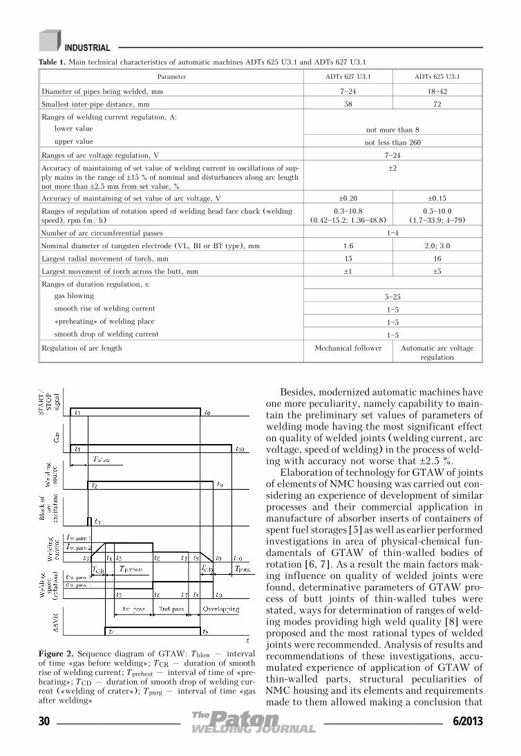
Besides, modernized automatic machines haveone more peculiarity, namely capability to main-tain the preliminary set values of parameters ofwelding mode having the most significant effecton quality of welded joints (welding current, arcvoltage, speed of welding) in the process of weld-ing with accuracy not worse that ±2.5 %.
Elaboration of technology for GTAW of jointsof elements of NMC housing was carried out con-sidering an experience of development of similarprocesses and their commercial application inmanufacture of absorber inserts of containers ofspent fuel storages [5] as well as earlier performedinvestigations in area of physical-chemical fun-damentals of GTAW of thin-walled bodies ofrotation [6, 7]. As a result the main factors mak-ing influence on quality of welded joints werefound, determinative parameters of GTAW pro-cess of butt joints of thin-walled tubes werestated, ways for determination of ranges of weld-ing modes providing high weld quality [8] wereproposed and the most rational types of weldedjoints were recommended. Analysis of results andrecommendations of these investigations, accu-mulated experience of application of GTAW ofthin-walled parts, structural peculiarities ofNMC housing and its elements and requirementsmade to them allowed making a conclusion that
Figure 2. Sequence diagram of GTAW: Tblow – intervalof time «gas before welding»; TCR – duration of smoothrise of welding current; Tpreheat – interval of time of «pre-heating»; TCD – duration of smooth drop of welding cur-rent («welding of crater»); Tpurg – interval of time «gasafter welding»
Table 1. Main technical characteristics of automatic machines ADTs 625 U3.1 and ADTs 627 U3.1
Parameter ADTs 627 U3.1 ADTs 625 U3.1
Diameter of pipes being welded, mm 7—24 18—42
Smallest inter-pipe distance, mm 58 72
Ranges of welding current regulation, A:
lower value not more than 8
upper value not less than 260
Ranges of arc voltage regulation, V 7—24
Accuracy of maintaining of set value of welding current in oscillations of sup-ply mains in the range of ±15 % of nominal and disturbances along arc lengthnot more than ±2.5 mm from set value, %
±2
Accuracy of maintaining of set value of arc voltage, V ±0.20 ±0.15
Ranges of regulation of rotation speed of welding head face chuck (weldingspeed), rpm (m/h)
0.3—10.8(0.42—15.2; 1.36—48.8)
0.5—10.0(1.7—33.9; 4—79)
Number of arc circumferential passes 1—4
Nominal diameter of tungsten electrode (VL, BI or BT type), mm 1.6 2.0; 3.0
Largest radial movement of torch, mm 15 16
Largest movement of torch across the butt, mm ±1 ±5
Ranges of duration regulation, s:
gas blowing 5—25
smooth rise of welding current 1—5
«preheating» of welding place 1—5
smooth drop of welding current 1—5
Regulation of arc length Mechanical follower Automatic arc voltageregulation
30 6/2013

the spigot-and-socket type joints are the mostreasonable for manufacture of NMC housing.Considering this, welded joints of NMC housing
elements (see Figure 1), i.e. nozzle 1 with insert2 (weld No.1), penetration 3 with insert 2 (weldNo.2) and insert 4 (weld No.3), insert 4 withbody 5 (weld No.4), pipe 6 with pipe 7 (weldNo.6) and pipe 7 with tip 8 (weld No.7), wereworked though as spigot-and-socket ones andjoining of pipe 6 with body 5 (weld No.5) as alap joint of different thickness parts.
Ranges of optimum values of GTAW modesfor joints of NMC housing were determinedthrough performance of several series of testwelding on full-size specimens (models) of ele-ments of NMC housing. All the specimens weredegreased during preparation to welding andjoint assembly for welding was carried out inaccordance to schemes, given in Table 2 and Fi-gure 3; at that tight fit (class III, accuracy degree8) of mating parts was provided.
Welding of joints of specimens of NMC hous-ing elements was carried out with variation ofmain parameters of welding mode (welding cur-rent, arc voltage and length, welding speed) andparameters of welding cycle (time intervals «gasbefore welding», «preheating», «gas after weld-ing»; duration of smooth of rise and drop of weld-ing current), as well as consumption of inert gas(argon), corresponding to GOST 10157.
Test welding was carried out using weldinghead ADTs 627.03.00.000 in order to determinethe ranges of optimum values of parameters ofGTAW modes for joints of pipes between them-selves (weld No.6), pipe to tip (weld No.7) andpipe to body (weld No.5). At that welding ofweld No.6 was performed at normal orientationof axis of non-consumable electrode to longitu-dinal axis of butt joint, welding of welds Nos. 7and 5 – at certain shifting (up to 0.5 mm) fromthe butt axis and electrode incidence at 15° angle(relatively to normal line) in the direction oflager heat sink in accordance to recommendationsof [5, 7].
Welding head ADTs 625.03.00.000 with nor-mal orientation of axis of non-consumable elec-trode to longitudinal axis of butt joint was used
Table 2. Schemes of assemblies of joints of NMC housing ele-ments for GTAW
Joint Type of joint
Nozzle 1 – insert 1(weld No.1)
Insert 2 – penetration 3(weld No.2)
Penetration 3 – insert 4(weld No.3)
Insert 4 – body 5(weld No.4)
Body 5 – pipe 6(weld No.5)
Pipe 6 – pipe 7(weld No.6)
Pipe 7 – tip 8(weld No.7)
Figure 3. Scheme of joint preparation of NMC housingelements (weld No.3) for GTAW
6/2013 31

for test welding of specimens of the rest jointsof NMC housing.
Quality of joints obtained as a result of testwelding was evaluated by means of non-destruc-tive testing methods (visual-measurementmethod and leakage tests) as well as with thehelp of mechanical tests, metallographic investi-gations and tests to intercrystalline corrosion(ICC) resistance. Visual-measurement testingwas carried out in accordance to normative docu-ments [9] currently in force in area of powerengineering with the help of micrometer gage,lens, binocular microscope (magnification 8—10)and corresponding templets. Leakage test wasperformed with the help of mass spectrometerand helium leak detector PTI-10 using methodof vacuum chamber in accordance to the require-ments and procedure given in [10]. Mechanicaltests were carried out based on GOST 1497 onmachine of ZDM-10 test type for spigot-and-socket joint of NMC housing with the smallestcross-section over the base metal (weld No.6).
It was determined as a result of the mechanicaltests that breaking force for this joint makes notless that 4807 N (490 kgf) at penetration depth40—50 % and not less than 11380 N (1160 kgf)at 90—100 % penetration depth. Metallographicinvestigations were carried out on macrosections(cut out from joints obtained by test welding)using metallographic microscope with 50—100magnification. At that, depth of penetration,presence in metal of such defects as non-metallic
inclusions, pores, wormhole and lacks of fusion,structure of weld metal and HAZ, dimensions ofaustenite grains were determined. Tests to ICCresistance of weld metal and HAZ were carriedout on AMU method (GOST 6032).
Performance of several series of test weldingof joints of elements of NMC housing, compre-hensive quality testing of these joints and systemanalysis of obtained results allowed determiningthat constantly high quality of welded joints ofelements is achieved in single-pass GTAW (val-ues of the main parameters of welding modes andcycles should correspond to given in Table 3). Itwas also stated that feeding of inert gas (argon)inside the housing is necessary to be provided inperformance of GTAW of any from indicatedjoints. Method for removal of such visible defectsof welds as partial lack of penetration, singlepores, unallowable nonuniformity of penetration(caused, mainly, by deviation of requirements onquality of preparation and assembly of parts forwelding) was worked as well. It lies in perform-ance of the second pass with the lower (in com-parison with the first pass) values of weldingcurrent or with the higher welding speed.
Besides, it should be noted that presence ofpipe-pipe joint (weld No.6) in NMC housingstructure is not necessary. It should be performedonly in the case of absence of one-piece pipe de-livery.
«Energoeffektivnost» developed a set of tech-nological fixture for providing of possibility of
Table 3. Main parameters of modes and cycles of single-pass GTAW of joints of NMC housing elements
Parameter
Joints of NMC housing elements
Nozzle—insert
(weld No.1)
Insert—pene-tration
(weld No.2)
Penetration—insert (weld
No.3)
Insert—body (weld No.4)
Body—pipe(weld No.5)
Pipe—pipe(weld No.6)
Pipe—tip(weld No.7)
Diameter of tungsten electrode, mm 2.0 1.6
Welding current, A 65—80 25—28 11—15 18—20
Arc voltage, V 9.0—10.5
Arc length, mm 1.0±0.1
Welding speed, m/h (rpm) 22.60—31.65 (5.66—7) 12.0—14.3(8.5—10)
11—15(7.8—10.6)
12—14.3(8.5—10)
Duration, s:
gas blowing 5—10
smooth rice of welding current 1.0±0.2
«preheating» of welding place 0.8±0.1 0.70±0.05 0.40±0.05 0.60±0.05
drop of welding current 4.0±0.5
gas purging 8—18
Consumption of shielding gas, l/min 6—7
Note. Grade of tungsten electrode: VT, VI, VL on GOST 23949—80 or Abicor Binzel WT, WR, Wr-2D.
32 6/2013
performance of GTAW of joints of NMC housingelements (in determination of ranges of optimumvalues of welding mode and cycle parameters).Testing of GTAW processes of NMC housing ele-ments developed in REC WCPE on full-size mod-els (experimental specimens) of NMC housingswas also carried out in this organization underconditions close to industrial one. It showed thatconstantly high quality of welded joints isachieved in application of developed technology.
Conclusions
1. Technology of single-pass GTAW of joints ofthin-walled different thickness bodies of rotationusing ADTs 627 U3.1 and ADTs 625 U3.1 auto-matic machines for orbital welding was devel-oped. It provides performance of high-qualityspigot-and-socket joints of NMC housing ele-ments.
2. Commercial application of developedGTAW technology and means of technologicalfixture allow manufacturing NMC and similarparts at domestic enterprises in volumes necessaryfor power engineering.
1. Cameron, I. (1987) Nuclear reactors. Moscow: Ener-goatomizdat.
2. Shirokov, S.V.(1993) Physics of nuclear reactors:Manual. Kyiv: Vyshcha Shkola.
3. Trofimov, N.A., Lappo, V.V. (1979) Measurement ofparameters of thermophysical processes in nuclearpower engineering. Moscow: Atomizdat.
4. Makhlin, N.M., Korotynsky, A.E., Bogdanovsky,V.A. et al. (2011) Single- and multioperator systemsfor automatic welding of position butt joints of nu-clear power plant piping. The Paton Welding J., 11,28—36.
5. Bogdanovsky, V.A., Gavva, V.M., Makhlin, N.M. etal. (2011) Application of automatic orbital weldingto fabricate absorbing inserts for spent nuclear fuelstorage containers. Ibid., 12, 34—37.
6. Ishchenko, Yu.S. (2002) Physical-technological prin-ciples of weld formation in arc welding process. In:Welding in nuclear industry: Transact. of NIKIMT.Moscow: IzdAT, Vol. 2, 204—240.
7. Bukarov, V.A. (2002) Technology of automaticshielded arc welding. Ibid., Vol. 1, 149—210.
8. Poloskov, S.I., Bukarov, V.A., Ishchenko, Yu.S.(2000) Influence of parameter deviations of argon-arcposition butt welding on quality of welded joints. In:Proc. of All-Russian Sci.-Techn. Conf. (Moscow,Sept. 2000). Moscow: MEI, 22—25.
9. PN AE G-7-016—89: Unified procedure of control ofbase materials (semi-products) of welded joints andsurfacing of equipment and pipelines of nuclearpower plant. Visual and measuring control. Moscow:Energoatomizdat.
10. PN AE G-7-019—89: Unified procedure of control ofbase materials (semi-products) of welded joints andsurfacing of equipment and pipelines of nuclearpower plant. Control of tightness. Gas and liquidmethod. Moscow: Energoatomizdat.
Received 27.03.2013
6/2013 33

AUTOMATIC SUBMERGED ARC SURFACINGOF STRUCTURAL STEELS WITH TRANSVERSE
HIGH-FREQUENCY MOVEMENTS OF ELECTRODE
Zh.G. GOLOBORODKO, S.V. DRAGAN and I.V. SIMUTENKOVAdmiral S.O. Makarov National Shipbuilding University
9, Geroev Stalingrada Ave, 54025, Nikolaev, Ukraine. E-mail: [email protected]
Transverse oscillations of the electrode in automatic submerged arc surfacing are one of the ways of decreasein penetration depth and share of base metal in deposited one. These oscillations can be created by generatingof high-frequency transverse pulsed movements of electrode wire using a specially designed electromechanicalgenerator. The aim of this work is to evaluate the effect of high-frequency low-amplitude transverse pulsedmovements of electrode wire on geometry of deposited bead and efficiency of the surfacing process. Depositionof beads was made on plates of low-carbon structural steel with electrode wire Sv-0.8A of 2 mm diameterunder flux AN-348A. The pulsed electrode movements at 0.25—5 kHz frequency were generated along thesurfacing direction. It was found that with increase in frequency the penetration depth of base metal andbead width are decreased, while the height of bead is increased, in addition the surfacing efficiency is alsochanged. The nature of change in the mentioned parameters depends on mode of pulsed effect on electrodewire, i.e. the presence or absence of resonance. The most significant change in geometry of the depositedbead is observed in the region of frequencies of the first resonance (0.55—0.75 kHz), namely depth ofpenetration and share of base metal in deposited one is 3 times decreased. The maximum increase in efficiencyis occurred in the region of the second resonance (3.75—3.85 kHz), the coefficient of electrode melting isincreased by 10—20 % as compared with surfacing without a pulsed effect. 10 Ref., 1 Table, 4 Figures.
Keywo r d s : automatic arc surfacing, low-carbonstructural steels, high-frequency pulsed movement, me-chanical generator, geometry of deposited bead
The repair of worn-out parts of ship machinesand mechanisms is often performed using theautomatic submerged arc surfacing (ASAS)which provides, alongside with high efficiency,the required quality and homogeneity of the de-posited layer. However, the depth of base metalpenetration is increased and its share in depositedone amounts as a rule to 30—50 % [1]. The re-duction of the mentioned characteristics of ASAStechnology, preserving the high efficiency of theprocess, is a very urgent problem. To solve thisproblem, different methods of effect on the proc-esses of electrode metal arc transfer or formationof weld pool are used allowing control the geo-metric parameters of the deposited bead and, con-sequently, the share of base metal (SBM) in thedeposited layer. The most widely spread are theelectric (pulsed-arc welding), mechanical (vibro-arc surfacing) and magnetic methods [2, 3].
It should be noted that the electric methodenvisages the application of complicated and ex-pensive welding current sources with program-ming of condition parameters [4], magneticmethod has some limitations connected with mag-
netic properties both of base metal and also elec-trode metal [5].
The listed drawbacks, in our opinion, are nottypical of the mechanical method, characterizedby simplicity in realization using the serial weld-ing equipment. It is known that the pulsed feed-ing of electrode [6] or generation of transverselow-frequency (up to 150 Hz) oscillations of elec-trode [7] increase the arcing stability, improvethe weld geometry and structure. High-frequency(500—1000 Hz) low-amplitude (about 130 μm)transverse pulsed movements of electrode con-tribute to reduction in penetration depth andSBM at ASAS as well [8]. In the latter case theeffect is attained due to periodic forced removalof liquid-metal layer from electrode end at vi-bration effect allowing control of metal dropmass, transferred through the arc.
The aim of the present paper is to investigatethe effect of transverse high-frequency pulsedmovement of electrode on geometric charac-teristics of deposited bead and technologicalcharacteristics of process in single-arc ASAS ofstructural steels.
Generator of transverse high-frequency move-ments of electrode wire (EW) represents a me-chanical drive (Figure 1), easily mounted onwelding tractor with a wide range of pulsed effectfrequency [8].
© Zh.G. GOLOBORODKO, S.V. DRAGAN and I.V. SIMUTENKOV, 2013
34 6/2013

The pulsed effect on EW leads to transverseoscillations of its end in two modes: interreso-nance and resonance. Within the region of fre-quencies close to resonance, the amplitude of os-cillations is abruptly increased, due to which thegeometry of deposited bead can significantlychange. The resonance frequency, at which thefrequencies of pulsed effect and natural oscilla-tions of EW coincide, can be presented in theform of [9]
foi = de
8π ⎛⎜⎝Eγ⎞⎟⎠
0.5
⎛⎜⎝
⎜⎜
pi
ls
⎞⎟⎠
⎟⎟
2
,
where de, E, γ are the diameter, elasticity modu-lus and density of EW metal, respectively; pi == kls are the roots of frequency equation deter-mined by nature of fixation of rod end subjectedto oscillations, i.e. by scheme of EW fixation incurrent conductor; ls is the stickout length; isthe Krylov function.
The current conductors, mostly widely usedin serial tractors for ASAS, can be conditionallycombined into two calculation schemes, realizinghinged (Figure 2, a) or rigid (Figure 2, b) fixa-tion of electrode. The values of the first two rootsof the frequency equation, respectively for thescheme presented in Figure 2, a are equal p1 == 3.9266 and p2 = 7.0685, and for scheme inFigure 2, k, p1 = 1.8751 and p2 = 4.6941 [10].
It is possible to control the resonance fre-quency according to above-given equation bychange in stickout length or nature of electrodefixation in current conductors. Thus, in the rangeof 100—1000 Hz frequencies the resonance oscil-lations for electrode diameter de = 2 mm takeplace at stickout length ls = 25—80 mm, and forde = 5 mm, respectively, at ls = 40—150 mm. In
this case the increase in stickout length and ri-gidity of electrode fixation in current conductorleads to reduction in resonance frequency.
The drawback of method of metal arc transferprocess control with applying the resonance phe-nomenon is the discrete change in resonance fre-quencies.
In the interresonance mode of pulsed effect itis possible to control smoothly the amplitude ofelectrode end oscillations in narrow range (1—3 mm) either by increase in stickout length ls orby decrease in arm hf of force applying F(t)p.However, the length of electrode stickout is de-termined, as a rule, in selection of parameters ofsurfacing conditions and cannot be freelychanged, and arm hf is limited by value of bend-ing moment, causing the plastic deforming ofEW [8].
It is sufficiently simply to control the ampli-tude of EW end oscillation by changing the fre-quency of pulsed effect. With increase in fre-quency the speed and acceleration of transmissionlink (generator striker) are increased, thus lead-
Figure 1. Design of generator of high-frequency pulsed movements of electrode (a) and its mounting on welding tractor(b): 1 – striker; 2 – fastening bracket; 3 – electric motor; 4 – reduction gear; 5 – body; 6 – driven washer; 7 –set-up rollers
Figure 2. Designs of current conductor and appropriatecalculation schemes of applying the force of pulsed effectF(t)p with continuous (a) and discrete (b) compensationof wear: hf – arm of F(t)p force applying
6/2013 35

ing to increase in inertial component of forceF(t)p.
This assumption was confirmed by the resultsof a special experimental investigation. Duringexperiments the length of trace, remained on thesample of plastic material, was measured by os-cillating sharpened end of EW. It was found(Figure 3) that with increase in frequency ofpulsed effect the amplitude of oscillations is in-creased by parabolic law (see dashed line in Fi-gure). Moreover, at frequencies close to reso-nance for the given stickout of EW, the abruptincrease in amplitude of oscillations is observed.
The amplitude of oscillations of electrode endcan be adjusted by two methods: step-wise bychange in mass of generator striker or value ofits movement in a pulse, as well as smoothly byvarying the frequency of rotation of driven elec-tric motor shaft.
The effect of transverse high-frequency pulsedmovements of electrode on geometric charac-teristics of deposited bead was evaluated fromresults of investigations made on experimentalstand (see Figure 1, b), equipped by weldingtractor KA-001 with a generator of high-fre-quency pulsed movements of electrode and powersource KIU-501.
Bead depositing was made by EW Sv-08A of2 mm diameter under flux AN-348A on 10 mmthick plate of low-carbon structural steel St3sp(killed). In experiments only frequency of pulsedeffect was varied, remaining other parameters ofwelding conditions unchanged. Stability of weld-ing process, recorded by electron USB-oscil-lograph IRIS, was evaluated from oscillogramsof arc voltage. Geometric parameters of depositedbeads, area of penetration and surfacing, andSBM were determined from macrosections.
Below the results are presented, correspond-ing to pulsed effect on EW along the surfacingdirection. It was found that with increase in fre-quency of pulses the bead width and depth ofpenetration of base metal are decreased, and beadheight is increased (Figure 4).
The nature of the above-mentioned parametersdepends on mode of pulsed effect on EW, i.e.the presence or absence of resonance. At the reso-nance condition the «extremal» change in beadgeometry with appropriate change in SBM is ob-served (Table).
Maximum effect was attained at main tone(first resonance) of oscillating system within the
Effect of frequency of pulsed movements of electrode at ASAS onformation of bead, SBM and coefficient of melting
Frequency f,Hz
Macrosection ofdeposited bead
SBM Km, g/(A⋅h)
0 0.36 15.4
680 (fr1) 0.13 16.9
1295 0.30 15.0
3820 (fr2) 0.22 18.6
5800 0.25 16.1
Figure 3. Effect of frequency on amplitude of oscillationsof 2 mm diameter EW end: fr – resonance frequency
Figure 4. Effect of frequency of pulsed movements of electrodeon geometric parameters e, g and h of deposited bead at de= 2 mm, I = 200 A, vw = 19 m/h, ls = 48 mm: e – beadwidth; g – height; h – depth of penetration of base metal
36 6/2013

range of frequencies fr1 = 560—750 Hz. This iswell correlated with resonance frequency fr == 630 Hz, calculated using equation above-given.
The interresonance mode of oscillations leadsto a smooth change in bead geometry. With in-crease in frequency the force effect of electrodemetal drops on weld pool is increased. The depthof penetration and SBM due to it are increasedlogically.
The high-frequency pulsed movements of elec-trode have an effect also on the surfacing effi-ciency. Increase in frequency and amplitude pro-motes the decrease in thickness of liquid-metallayer at the EW end, increase both in heat trans-fer from arc to electrode and also in coefficientof electrode melting. Thus, at 3820 Hz frequencyof the first overtone the coefficient of meltingexceeds the initial value by more than 20 % (seethe Table).
Conclusions
1. Applying the high-frequency mechanicalpulsed effect on EW allows control the metaltransfer process, sizes of deposited bead and ef-ficiency of ASAS process.
2. Transverse mechanical oscillations of EWhave the highest effect in the region of resonancefrequencies of the first tone – on the geometricparameters of deposited bead, and of the secondtone – on the efficiency of electrode melting.
3. ASAS of structural steels the mechanicalpulsed effect on EW within ranges of frequencies
of 600—4000 Hz allows 3 times decreasing thedepth of penetration and SBM, and increasingthe coefficient of electrode melting by 10—20 %.
1. (1974) Technology of fusion electric welding of met-als and alloys. Ed. by B.E. Paton. Moscow: Mashi-nostroenie.
2. Najdenov, A.M. (1998) Calculation of electrode wiremelting rate in mechanized methods of arc welding.Svarochn. Proizvodstvo, 6, 10—14.
3. Tarasov, N.M. (1984) Energy calculation of electrodemetal drop detachment under action of pulse of exter-nal electromagnetic field. Avtomatich. Svarka, 6,21—25.
4. Lebedev, V.A. (2008) Aspects of choice of electricarc and automatic welding equipment with pulsedfeed of electrode wire. Svarochn. Proizvodstvo, 5,45—49.
5. Razmyshlyaev, A.D., Mironova, M.V. (2011) Effi-ciency of electrode wire melting in submerged arcsurfacing under action of transversal magnetic field.Visnyk Donbas. Derzh. Mashynobud. Akademii, 1,142—147.
6. Lebedev, V.A., Kuzmin, I.S., Novgorodsky, V.G. etal. (2002) Control of mechanized CO2 welding proc-ess using parameters of electrode metal transfer.Svarochn. Proizvodstvo, 5, 6—14.
7. Alov, A.A., Vinogradov, V.S. (1958) Effect of elec-trode vibration on arc welding process and propertiesof welds. Ibid., 9, 19—22.
8. Dragan, S.V., Simutenkov, I.V. (2011) Developmentof device for control of weld geometric parameters inautomatic submerged arc surfacing. Zbirnyk Nauk.Prats NUK, 3, 59—64.
9. (1970) Physics and technique of power ultrasound.Vol. 3: Physical principles of ultrasonic technology.Ed. by L.D. Rozenberg. Moscow: Nauka.
10. (1970) Physics and technique of power ultrasound.Vol. 1: Supplies of power ultrasound. Ed. by L.D.Rozenberg. Moscow: Nauka.
Received 04.02.2013
6/2013 37

WELDS FORMATION IN EBW OF HEAT-RESISTANTSTEELS OF THE GRADES 10Kh9MFBA AND 10Kh12M
V.M. NESTERENKOV, L.A. KRAVCHUK, Yu.A. ARKHANGELSKY and A.A. BONDAREVE.O. Paton Electric Welding Institute, NASU
11 Bozhenko Str., 03680, Kiev, Ukraine. E-mail: [email protected]
The influence of both the conditions of electron beam welding of heat-resistant steels 10Kh12M and10Kh9MFBA 30 mm thick without preheating and also the spatial arrangement of electron beam relativelyto the part being welded on weld formation and tendency to crack formation was investigated. It wasestablished that in EBW of the mentioned heat-resistant steels without preheating the elimination of cracksand elongated cavities is achieved at the speed of welding of not more than 3 mm/s. The reproducibilityof quality welds and formation of narrow and deep welds with parallel walls of cast zone is possible byapplication of technological scanning of electron beam around the circle and elliptic trajectory, and alsoarrangement of electron beam focus at the level of 2/3 of the specimen thickness. In the development ofEBW technology of heat-resistant steels the non-destructive method of ultrasonic testing can be recommendedfor application. 6 Ref., 1 Table, 6 Figures.
Keywo r d s : electron beam welding, heat-resistantsteels, electron beam, welding scheme, energy input,welding speed, focusing, defects, middle cracks, faceand reverse weld beads
In manufacture of such critical assemblies in ma-chine building as bodies of drums, steam lines,diaphragms, rotors, discs, turbine blades andother high-loaded parts the heat-resistant steelsof martensite-ferrite class are widely applied. Re-lating to the category of steels with a limitedweldability, they require obligatory preheatingin arc welding as they are susceptible to partialhardening with formation of martensite struc-tures and cracks, and postweld tempering. Thesesteels obtain the optimal properties as a resultof double heat treatment by normalization + tem-pering or hardening + tempering, and are usuallysupplied for welding after final heat treatment.
EBW, the thermal cycle of which is featuredby high rates of heating and cooling due to lowvalue of energy input and also metal short-timeduration at high temperatures, begins to occupystrong positions in power machine building. Ascompared to the arc welding, in ESW the sizesof near-weld zone and HAZ are decreased andalso development of structure changes and defor-mations is delayed, which allows improving themechanical characteristics of welded joints. Theuse of vacuum in EBW perfectly protects themolten metal from interaction with environment,which facilitates the improvement of quality ofwelded joints.
In this work the influence of conditions ofEBW of heat-resistant steels of the grades
10Kh12M and 10Kh9MFBA of thickness δ == 30 mm without preheating and also spatial lo-cation of electron beam relatively to the partbeing welded on welds formation and their ten-dency to cracks formation was investigated. Itshould be noted that investigated steels (Table)were supplied for welding under different heatconditions to obtain moderate levels of strengthof base metal:
• 10Kh9MFBA alloy was subjected to the pro-cedure of normalization + tempering: at normali-zation the specimens were heated to 1040—1095 °C, then the holding for 72 min and aircooling were followed; in tempering the speci-mens were heated to 770±10 °C, then the holdingfor 72 min and air cooling were followed;
• 10Kh12M alloy was subjected to the proce-dure of hardening + tempering: in hardening thespecimens were heated to 1050 °C with sub-sequent cooing in oil; in tempering the specimenswere heated to 720 °C with subsequent air cool-ing.
The welding of specimens was performed inthe installation UL-209M with the power unitELA-60/30 composed of EB gun with metalcathode and short-focus optics with electronbeam current Ib = 0—500 mA. The tendency tocracks formation was determined on 200 ×× 100 mm size butt specimens of δ = 30 mm. Thecontrol of electrode beam focusing on the surfaceof specimen was carried out according to thesharpness of image on the monitor of RASTRmonitoring system [1], and at the same time ac-cording to the brightness of illumination of cir-
© V.M. NESTERENKOV, L.A. KRAVCHUK, Yu.A. ARKHANGELSKY and A.A. BONDAREV, 2013
38 6/2013

cular beam scanning of dcirc = 5 mm with Ib ≅≅ 10 mA on the copper massive plate. The narrowdeep welds with parallel walls of cast zone wereproduced by deepening of electron beam focusinside the specimen, and also beam scanningaround the circle or ellipsis, which provided the≤5⋅10—2 rad convergence angle of beam at theworking distance from lower end of gun to thespecimen lwork = 200—250 mm [2, 3]. The pres-ence of defects of welded joint formation wasdetected by non-destructive method of ultrasonictesting and further metallographic examinations.To eliminate the residual magnetization, all thespecimens of investigated heat-resistant steelswere subjected to additional demagnetization ona special stand and supplied for welding with themagnetization level of not more than 0.5 Gs.
At first, to produce the guaranteed weld for-mation on the investigated heat-resistant steelsof δ = 30 mm, the through penetrations alongthe solid metal according to the scheme in flatposition (vertical electron beam) at movementof EB gun along the coordinates X—X or Y—Ywere performed. As a result, during change ofbeam current Ib in a wide range, focusing currentIf and welding speed vw the defect-free weldcould not be formed as far as on the face beadthe non-regular depressions and undercuts ofweld and wavy non-regular sagging of weld metalon reverse bead were formed.
To eliminate the defects of weld formation atthrough penetration of specimens of δ = 30 mmaccording to the scheme in flat position, the tech-nological backing 8 mm thick from material tob welded was applied. The Ib value was selectedso that in welding process the single spot pene-trations (peens) could be made. As the results ofthrough penetrations showed, in welding withtechnological backing the face bead is formedregularly without depressions and undercuts onthe both investigated steels.
Tendency of steels 10Kh12M and10Kh9MFBA to cracks formation was investi-gated after a number of through penetrations onsolid metal of δ = 30 mm made according to the
scheme in flat position with technological back-ing at vw = 3, 6, 9 and 12 mm/s. The mode ofpenetration of specimens for both investigatedsteels at each selected speed of weldiand was notchanged. The focusing current was preset so thatelectron beam focus was positioned below thesurface of specimen at the level of 2/3 of thick-ness of specimen; for this case the value of partialfocusing of electron beam from the value of fo-cusing current on the surface of specimen corre-sponds to —ΔIf = 15 mA. At lwork = 200 mm thetechnological electron beam scanning around circleof fr = 500 Hz frequency amounted to dcirc == 1.5 mm.
Ultrasonic testing and metallographic exami-nations of welded joints on the specimens of δ == 30 mm showed that steel 10Kh12M has no ten-dency to cracks formation at vw = 3—6 mm/s;only at vw = 9 and 12 mm/s the macrodefect inthe form of a middle crack of about 3 mm lengthand 0.05 mm width was detected approximatelyat the half of penetration depth. As is seen fromFigure 1, with increase in speed of welding theweld configuration is changed: the width of facebead decreases, transverse section from conicalone is approaching the cylindrical one. The facebead is formed at all speeds with reinforcement,undercuts on the edges of weld are absent. Thedetected middle crack of the sizes mentionedabove was detected using ultrasonic testing.
Unlike steel 10Kh12M, in EBW of specimensof steel 10Kh9MFBA of δ = 30 mm the quitedifferent results on tendency to cracks formationaccording to the scheme in flat position withtechnological backing were obtained. As metal-lographic examinations of welded joints showed,the cracks are absent at vw = 3 mm/s (Figure 2,a); at vw = 6, 9 and 12 mm/s the defects asmiddle cracks are detected, propagating in ver-tical direction along the weld axis from reinforce-ment to the root (Figure 2, b—d). The geometricsizes of middle cracks in upper and root part ofa weld are practically similar to the defects onsteel 10Kh12M.
Chemical compositions of investigated heat-resistant steels, wt.%*
Grade of steel C Si Mn Cr Mo V Nb Cu Ni Other
10Kh9МFBА 0.07—0.13 0.15—0.55 0.27—0.63 7.9—9.6 0.8—1.1 0.16—0.27 0.05—0.11 ≤ 0.25 ≤ 0.43 S ≤ 0.01P ≤ 0.02
10Kh12М 0.10—0.15 ≤ 0.50 ≤0.60 11.5—13.0 0.3—0.6 — — ≤ 0.30 0.30—0.60 S ≤ 0.03Р ≤ 0.03
*Additional investigations on spectral analysis revealed gases in 10Kh9MFBA alloy: [O2] ≤ 0.0037, [N2] ≤ 0.0386, [H2] ≤ 0.0009; in10Kh12M alloy: [O2] ≤ 0.0033, [N2] ≤ 0.0310, [H2] ≤ 0.0008 wt.%.
6/2013 39

Thus, basing on the obtained results ofthrough penetration of specimens of δ = 30 mmit can be concluded that with increase of weldingspeed the tendency to cracks formation on theinvestigated steels 10Kh9MFBA and 10Kh12Mis increased, and this proves, in its turn, the factthat with increase of welding speed the increaseof both welding stresses and also rate of growingof inner strains in welding occur. In other words,with increase of welding speed the quicker so-lidification of weld metal occurs, which leads toa higher rate of deformations growing [4, 5].Therefore, the welding speed of not more than3 mm/s can be more rational to be recommendedfor practical use of steels 10Kh12M and10Kh9MFBA 30 mm thick in EBW.
According to the results of through penetra-tions of the specimens of heat-resistant steels10Kh12M and 10Kh9MFBA 30 mm thick accord-ing to the scheme in flat position with techno-logical backing (see Figures 1 and 2) the depend-encies of energy input in EBW and width of facebead on the speed of welding were plotted. Asis shown in Figure 3, with increase of welding
speed in the range 3—12 mm/s the values ofenergy input q/v and width of face weld beadB are decreased in non-linear way according tohyperbolic law (1/vw)1/3: q/v = 2.56 kJ/mmand B = 5.8 mm at vw = 3 mm/s up to q/v == 1.55 kJ/mm and B = 3.5 mm at vw = 12 mm/s,i.e. by 1.66 times. At vw = 6 mm/s the value ofenergy input amounted to 1.84 kJ/mm andwidth of face weld bead B = 4.5 mm.
One can refuse from technological backings,having provided defect-free weld formation withthrough penetration, by transition to the schemeof EBW using horizontal electron beam andmovement of EB gun in horizontal plane alongthe coordinate X—X or Y—Y. This method turnedto be the most reliable and efficient, allowingelimination of root defects, reducing the angulardeformations to minimum, decreasing the prob-ability of pores formation and longitudinal cavi-ties due to improvement of conditions of degass-ing of weld pool metal.
The first through penetrations of the speci-mens of steels 10Kh12M and 10Kh9MFBA of δ == 30 mm using horizontal electron beam showed
Figure 1. Macrostructure (×1.5) of welded joints on 10Kh12M alloy of δ = 30 mm in flat position at Uacc = 60 kV, If == 630 mA, —ΔIf = 15 mA, dcirc = 1.5 mm, lwork = 200 mm: a – vw = 3 mm/s, Ib = 128 mA; b – vw = 6 mm/s, Ib == 184 mA; c – vw = 9 mm/s, Ib = 236 mA; d – vw = 12 mm/s, Ib = 310 mA
Figure 2. Macrostructure (×1.5) of welded joints on 10Kh9MFBA alloy of δ = 30 mm in flat position at Uacc = 60 kV,If = 630 mA, —ΔIf = 15 mA, dcirc = 1.5 mm, lwork = 200 mm (a—d – vw and Ib are the same as in Figure 1)
40 6/2013

that direction of gravity force of liquid metal ofweld pool has no considerable influence on se-lection of electron beam power, as compared tothe similar welding conditions in flat position.In this connection and considering the recom-mendations [6], the through penetrations ofspecimens of investigated heat-resistant steels30 mm thick with guaranteed face and reversebead formation at different positions of electronbeam focus relatively to the surface of specimenwere carried out. As is shown in Figures 4 and5, the face and reverse beads on the both steelsare formed stably and regularly without depres-sions and flowing out of weld metal in the wholerange of partial focusing —ΔIf = 13—25 mA (elec-tron beam focus is deepened inside the specimen),undercuts and visible defects are not observed.It should be noted that in welding of steel10Kh12M the intensive spattering of weld metalfrom the face side occurs, unlike that of steel10Kh9MFBA where EBW process is runningmuch more smoothly.
According to the results of through penetra-tions of specimens of steels 10Kh12M and10Kh9MFBA of δ = 30 mm using horizontal elec-tron beam and basing on the analysis of transverse
macrosections of welded joints given in Figures 4and 5, the dependencies of width of face andreverse beads on deepening of electron beam focusinside the specimen at q/v = 1.98 kJ/mm wereplotted. As is shown in Figure 6, the width ofreverse weld bead b in the whole range —ΔIf == 13—25 mA remains practically constant andamounts to b ≅ 2 mm, whereas width of face weldbead B with increase of deepening of electronbeam focus inside the specimen is decreased innon-linear way: to —ΔIf = 17 mA, where B is
Figure 3. Dependence of energy input (1) and width of faceweld bead (2) on speed of welding of steels 10Kh12M and10Kh9MFBA of δ = 30 mm in flat position at Uacc = 60 kV,—ΔIf = 15 mA, dcirc = 1.5 mm and lwork = 200 mm
Figure 4. Macrostructure (×2) of welded joints on 10Kh12M alloy of δ = 30 mm in welding using horizontal beam atUacc = 60 kV, Ib = 198 mA, vw = 6 mm/s, dcirc = 1.5 mm and lwork = 200 mm: a—d – respectively, —ΔIf = 25, 21, 17and 13 mA
Figure 5. Macrostructure (×2) of welded joints on 10Kh9MFBA alloy of δ = 30 mm in welding using horizontal beam(Uacc, Ib, vw, dcircl, lwork and a—d are the same as in Figure 4)
6/2013 41

sharply decreased, then to —ΔIf = 25 mA, wherethe decrease of B parameter is delayed.
Metallographic examinations carried out onthe welded joints of steels 10Kh12M and10Kh9MFBA of δ = 30 mm after EBW usinghorizontal electron beam allowed establishingthat position of electron beam focus relatively tothe surface of specimen influences not only theshape of weld but also can result in cracks for-mation. As is shown in Figures 4, a and 5, a, ata large deepening of electron beam focus insidethe specimen in the area of half of penetrationdepth on the both steels, the local widening ofweld and middle cracks in them of up to 10 mmlength are formed. With reduction of partial fo-cusing current —ΔIf, local widening of weld iseliminated, and at —ΔIf = 13—17 mA the weldshape from conical one is approaching the cylin-drical one.
Conclusions
1. Welds formation with through penetration onheat-resistant steels 10Kh12M and 10Kh9MFBAof δ = 30 mm is achieved in transition to thescheme of EBW using horizontal electron beamand movement of EB gun in horizontal plane.
2. In EBW of these steels without preheatingthe elimination of cracks is achieved at the speedof welding of not more than 3 mm/s.
3. The application of technological scans ofelectron beam around the circular and ellipticaltrajectory and location of electron beam focus atthe level of 2/3 of thickness of the specimenprovides reproducibility of quality welds and alsoformation of narrow and deep welds with parallelwalls of cast zone.
1. Nazarenko, O.K., Shapoval, V.I., Loskutov, G.A. etal. (1993) Observation of electron beam weldingprocess and automatic seam tracking. Avtomatich.Svarka, 5, 35—38.
2. Sayegh, G. (1986) State of the art of high energy den-sity beam welding: Houdremont Lecture. Tokyo: IIW.
3. Fritz, D. (1988) Electron beam welding of today. In:Proc. of 2nd Int. Conf. on Electron Beam Technolo-gies (Varna, 31 May—4 June 1988), 1048—1063.
4. Morochko, V.P., Sorokin, L.I., Zorin, N.Ya. (1975) In-fluence of electron beam welding mode on weld shapeand properties of heat-resistant alloy welded joints 10—15 mm thick. Svarochn. Proizvodstvo, 6, 32—36.
5. Shida, T., Kita, H., Okamura, H. et al. (1978) Ef-fects of welding parameters and prevention of defectsin deep penetration EBW of heavy section steel. IIWDoc. IV-239—78.
6. Petrenko, V.R., Olshansky, N.A., Lopatko, A.P. etal. (1985) Study of influence of beam focus deepen-ing in titanium specimens on weld formation stabilityin EBW. In: Proc. of 2nd All-Union Conf. on Cur-rent Problems of Welding of Non-Ferrous Metals.Kiev: Naukova Dumka, 223—226.
Received 25.03.2013
Figure 6. Dependence of width of face (1) and reverse (2)weld beads on deepening of electron beam focus in EBWof heat-resistant steels 10Kh12M and 10Kh9MFBA 30 mmthick using horizontal beam at Uacc = 60 kV, Ib = 198 mA,vw = 6 mm/s, dcirc = 1.5 mm and lwork = 200 mm
42 6/2013

WEAR RESISTANCE OF DEPOSITED METALOF THE TYPE OF CARBON
AND CHROMIUM-MANGANESE STEELSUNDER THE CONDITIONS OF DRY SLIDING FRICTION
OF METAL OVER METAL
V.D. KUZNETSOV1, D.V. STEPANOV1, V.A. MAKOVEJ1 and Ya.P. CHERNYAK2
1NTUU «Kiev Polytechnic Institute»6/2 Dashavskaya Str., 03056, Kiev, Ukraine. E-mail: [email protected]
2E.O. Paton Electric Welding Institute, NASU11 Bozhenko Str., 03680, Kiev, Ukraine. E-mail: office@paton, kiev.ua
Parts subjected to intensive wear are made from medium- and high-carbon unalloyed or low-alloyed structuralsteels. Increased carbon content ensures a high hardness and strength of materials. Because of low-alloying,however, their wear resistance is on a relatively low level. High carbon content considerably complicatesthe technology of reconditioning the above parts, because of the risk of cold cracking in arc surfacing. Torecondition this type of parts it is rational to apply consumables producing deposited metal with thestructure of metastable austenite. Such a structure can be produced at application of consumables alloyedby chromium and manganese for surfacing. Preliminary work hardening or work hardening directly duringservice leads to decomposition of metastable austenite and increase of hardness and wear resistance of thedeposited metal. The objective of the work was investigation of wear resistance of deposited metal ofchromium-manganese class under the conditions of dry sliding friction of metal over metal. Wear resistanceof deposited metal of various alloying systems was studied. It is shown that the correlation between hardnessand wear resistance is manifested not in all the cases, both for carbon and for austenitic materials. It isfound that materials with the structure of metastable austenite are superior to carbon steels as to wearresistance and are preferable at reconditioning of parts from structural medium- and high-carbon steels.6 Ref., 1 Table, 3 Figures.
Keywo r d s : arc surfacing, surfacing consumables,sliding friction, wear resistance, structure, hardness
A considerable number of parts of machines andmechanisms, used in various industries, wears asa result of dry friction of metal over metal. Manyof them are reconditioned by various surfacingprocesses [1—4].
Such parts are usually made from medium-and high-carbon unalloyed or low-alloyed struc-tural steels. Increased carbon content ensureshigh hardness and strength of materials. How-ever, because of low alloying their wear resis-tance is on a relatively low level. In addition, atmore than 0.5 % C, technology of reconditioningthe parts from above-mentioned steels by surfac-ing becomes much more complicated that is re-lated to formation of quenching structures andcold cracking in the HAZ metal.
Cracking can be avoided through applicationof special technological measures, such as heatingof the surfaced part up to 300—400 °C with sub-sequent delayed cooling after surfacing.
Application of consumables, providing depos-ited metal with austenitic structure, has a goodeffect in terms of crack resistance. However, wearresistance of deposited metal of this type under theconditions of dry sliding friction of metal over met-al is on a low level, while the price of consumablesfor this type of surfacing is quite high and theirapplication is not always cost-effective.
For reconditioning parts of this type, it ismore rational to apply consumables, which pro-vide deposited metal with the structure of me-tastable austenite. Such a structure can be ob-tained at application of surfacing consumablesalloyed by chromium and manganese. Prelimi-nary work hardening or in-service hardening leadto decomposition of metastable austenite, as wellas increase of hardness and wear resistance of thedeposited metal.
The objective of this work is investigation ofwear resistance of the deposited metal with dif-ferent content of chromium and manganese underthe conditions of dry sliding friction of metalover metal. Composition of the studied types ofdeposited metal is given in the Table. Samples of
© V.D. KUZNETSOV, D.V. STEPANOV, V.A. MAKOVEJ and Ya.P. CHERNYAK, 2013
6/2013 43

deposited metal of the type of high-carbon steelU7 were used as a reference. For comparison,deposited metal alloyed practically by manganesealone was studied, alongside chromium-manga-nese deposited metal of various compositions.
Investigation of wear resistance of depositedmetal was performed in friction machine of M-22type in «shaft—block» configuration. Samples of20 mm length and 10 mm thickness with a cy-lindrical slot in the form of a segment of 20 mmradius and 20 mm chord were used.
A disc of 40 mm diameter made from U7 steelwith HB 300—350 hardness was used as a coun-terbody.
Testing conditions were as follows: pressureon the sample p = 0.5 ± 0.1 MPa; friction speedv = 3 ± 0.25 m/s; temperature T = 60 ± 20 °C;duration t = 1 h.
Samples were weighed on laboratory scaleswith 0.0001 g error. Wear by weight Δm wasdetermined as difference of values of sampleweight before and after testing. Deposited metalhardness was also measured. Investigation resultsare given in Figure 1.
Deposited metal structure was identified bythe results of metallographic analysis (Figure 2).Producing structures of specified type was en-sured by selection of chemical composition ofsurfacing consumables and surfacing heat inputs.
Recommendations given in [5] were used in sur-facing of austenitic materials.
Testing results showed (see Figure 1) the ab-sence of a direct link between hardness and wearresistance of the studied types of deposited metal.
So, for instance, types of deposited metal U7,30Kh5G5 and 50G11M have approximately thesame wear parameters (Δm = 0.11—0.12 g), butdiffer considerably by hardness: 50G11M –HB 180; U7 – HRC 35; 30Kh5G5 – HRC 42.On the other hand, types of deposited metal20Kh13G6N6MFD and 50G11M have approxi-mately the same hardness – HB 150—180, butdiffer considerably as to wear – Δm = 0.062 and0.115 g, respectively.
Deposited metal structure has apparently sig-nificant influence on wear resistance. High-al-loyed 60Kh20G9N2MD deposited metal withaustenitic-martensitic structure had minimumwear (see Figure 2, d) and sufficiently high hard-ness HRC 30. Deposited metal 10Kh10G10, aswell as 20Kh13G6N6MFD and 50G11M, havingmetastable austenitic structure (Figure 2, c, e,f), had somewhat inferior wear resistance com-pared to it. It is obvious that the conditions ofwear testing (at relatively small load) did notallow full realization of the possibility of workhardening of these materials. Nonetheless, wearresistance of deposited metal 10Kh10G10 and20Kh13G6N6MFD is quite high and is much su-perior to that of hard materials U7 and 30Kh5G5.
From the studied materials having maximumwear resistance (10Kh10G10, 60Kh20G9N2MD,20Kh13G6N6MFD) preference, in our opinion,should be given to the first of them, not contain-ing any expensive alloying elements, and havingsufficiently high wear resistance.
It should be noted that the obtained data arein good agreement with those of [6] as to inves-tigation of wear resistance of steel U7 and de-posited metal of ferritic and austenitic classes.
After wear resistance testing, fractograms offriction surfaces of deposited metal samples werestudied (see Figure 3), and it was found that in10Kh10G10 sample with the structure of metas-table austenite (Figure 2, c) friction surface hasuniform relief without any traces of spalling orcharacteristic furrowed structure (Figure 3, a).
Figure 1. Wear by weight (I) and hardness (II) of depositedmetal: 1 – U7; 2 – 30Kh5G5; 3 – 10Kh10G10; 4 –60Kh20G9N2MD; 5 – 20Kh13G6N6MFD; 6 – 50G11M
Composition of deposited metal, wt.%
Deposited metal type C Cr Mn Ni Si Mo V Ti Cu
U7 0.70 — 0.89 — 0.25 — — — —
30Kh5G5 0.27 4.5 5.0 — 0.20 — — — —
10Kh10G10 0.11 11.0 10.0 — — — — 0.8 —
60Kh20G9N2MD 0.62 20.8 9.0 2.0 0.55 0.5 — — 0.17
20Kh13G6N6МFD 0.22 13.0 5.8 6.0 0.60 1.4 0.4 — 0.90
50G11М 0.50 0.2 11.0 — 0.80 0.3 — — —
44 6/2013

In 30Kh5G5 sample with martensitic-sorbiticstructure with residual austenite (see Figure 2,b), contrarily, the characteristic morphologicalfeature of friction surface is the furrowed struc-ture (Figure 3, b), which forms as a result ofplastic driving of material from friction surfaceby wear product particles. Geometrical dimen-sions of the grooves change in a wide range thatis indicative of structural inhomogeneity, and ofdifferent wear resistance of structural compo-nents of the considered type of deposited metal,respectively.
Conclusions
1. Wear resistance and microstructure of depos-ited metal of various types was studied. It isshown that the best wear resistance is found indeposited metal with the structure of metastableaustenite. Preliminary work hardening or in-serv-ice work hardening with increased mechanicalloads leads to decomposition of metastable
austenite and increase of deposited metal hard-ness and wear resistance.
2. From the studied types of deposited metalof various alloying systems, deposited metal10Kh10G10 has an optimum combination ofproperties.
1. Frumin, I.I. (1961) Automatic electric arc surfacing.Kharkov: Metallurgizdat.
2. Ryabtsev, I.A., Kondratiev, I.A. (1999) Mechanizedelectric arc surfacing of metallurgical equipmentparts. Kiev: Ekotekhnologiya.
3. Ryabtsev, I.A. (2004) Surfacing of machine andmechanism parts. Kiev: Ekotekhnologiya.
4. Kuskov, Yu.M., Skorokhodov, V.N., Ryabtsev, I.A.et al. (2001) Electroslag cladding. Moscow: Nauka iTekhnologiya.
5. Kalensky, V.K., Chernyak, Ya.P., Vasiliev, V.G. etal. (2001) Heat input influence on formation of tearsin high-carbon steel building-up with austeniticwires. The Paton Welding J., 11, 9—12.
6. Chernyak, Ya.P. (2007) Comparative evaluation ofwear resistance of electrode materials applied for re-conditioning tram rails. Ibid., 12, 33—35.
Received 21.03.2013
Figure 3. Fractograms of friction surfaces after wearing of deposited metal of the samples: a – 10Kh10G10; b –30Kh5G5
Figure 2. Microstructures (×500) of deposited metal: a – U7; b – 30Kh5G5; c – 10Kh10G10; d – 60Kh20G9N2MD;e – 20Kh13G6N6MFD; f – 50G11M
6/2013 45

DISTRIBUTION OF CHEMICAL ELEMENTSIN THE ZONE OF ALUMINIUM ALLOY AMg6
TO TITANIUM ALLOY VT6 JOINTSPRODUCED BY DIFFUSION WELDING IN VACUUM
Yu.V. FALCHENKO, E.V. POLOVETSKY and L.M. KAPITANCHUKE.O. Paton Electric Welding Institute, NASU
11 Bozhenko Str., 03680, Kiev, Ukraine. E-mail: [email protected]
The possibility of a combined use of titanium and aluminium alloys in the form of permanent joints is ofhigh interest to many industries. However, no investigations involving evaluation of the effect of thediffusion welding process on distribution of chemical elements and microstructure of the welded joints havebeen conducted so far. As revealed by the metallographic examinations carried out in this study, magnesiumduring the welding process diffuses from alloy AMg6 to the zone of joining with alloy VT6 and accumulatesin the contact region. An interlayer of aluminium AD1 was used to eliminate the negative effect of magnesium.A gradual decrease in the concentration of magnesium from AMg6 to AD1 was observed in the joining zonewhen using the aluminium interlayer. A region of diffusion interaction, in which titanium and vanadiumdiffused from VT6 to AD1, was detected in the AD1 + VT6 joining zone. It can be concluded from theinvestigation results that in vacuum diffusion welding of titanium alloys to aluminium alloys containingmagnesium the use of the interlayer of pure aluminium provides the sound welded joints with a gradualdistribution of magnesium in the joint. The main role in formation of the titanium alloy to interlayer jointis played by the processes of diffusion of titanium and vanadium in a direction of the interlayer. 7 Ref.,3 Figures.
Keywo r d s : diffusion welding in vacuum, weldedjoint structure, distribution of chemical elements, diffu-sion, diffusion interaction zone
The progress in modern machine building, aero-space, chemical and other engineering fields isrelated to the application of components madefrom aluminium and titanium alloys. Of the high-est interest to designers is the possibility of thecombined use of titanium and aluminium alloysin the form of permanent joints.
The problem of producing components fromsuch materials can be solved by using vacuum dif-fusion welding (VDW) [1—3]. Analysis of litera-ture data shows that no detailed investigations ofthe effect of distribution of chemical elements inthe welded joint on its microstructure have beenconducted up to now for this pair of alloys [4—6].
Welding of alloy AMg6 to alloy VT6 wasperformed both without interlayers and with aninterlayer of aluminium AD1. Welding parame-ters were as follows: pressure P = 20 MPa, timet = 20 min, and welding temperature T = 540 °C.Investigations were conducted on the sectionsmade from the investigated welded joints withtheir subsequent ion etching using the JEOL unitJFC-1100 (Japan) under the conditions speciallyselected and optimised for the investigated bi-
metal pairs. Investigations of distribution of che-mical elements were carried out by using theJEOL Auger microanalyser JAMP 9500F equip-ped with the «Oxford Instruments» energy-dis-persive X-ray spectrometer of the INCA system(Great Britain).
During welding the alloys are subjected tothe thermal-deformation effect. This causes oc-currence of the recrystallisation and diffusionprocesses in the joints, thus influencing the metalstructure and properties.
As shown by the investigations, it is impossi-ble to produce the welded joints between tita-nium alloy VT6 and aluminium alloy AMg6 bythe VDW method using no technological ap-proaches. Fracture of the resulting joints occursdirectly in the joint.
According to the Mg—Ti equilibrium consti-tutional diagram [7], magnesium is insoluble intitanium. In the course of the welding processmagnesium diffuses from AMg6 to the zone ofjoining with VT6, and accumulates there to formthe 15—17 μm wide region with a content of upto 11 wt.% (Figure 1, a). Titanium at a contentof up to 15 wt.% and vanadium of up to 1 wt.%were also detected in this region. The 3—4 μmdeep zones with an increased content of oxygen(up to 9 wt.%) were revealed on the contact© Yu.V. FALCHENKO, E.V. POLOVETSKY and L.M. KAPITANCHUK, 2013
46 6/2013

surfaces of both alloys. The zone on AMg6 con-tained also (wt.%) up to 30 Ti, up to 2 V andup to 9 Mg, while the zone on VT6 contained upto 4.5 Mg (Figure 1, b).
It is the formation of all these zones that pre-vents production of the welded joint. Therefore,the 150 μm thick interlayer of commercially purealuminium AD1 was used to avoid the negative
Figure 1. Microstructure and distribution of chemical elements in the AMg6 + VT6 welded joint produced by the VDWmethod without interlayers at tw = 20 min, Tw = 540 °C, Pw = 20 MPa: a – in an area of the layer with increasedcontent of magnesium, and in the base metals; b – in layers at the near-contact surfaces
Figure 2. Microstructure of the AMg6 + AD1 + VT6 joint(a), and distribution of magnesium in the AMg6 + AD1joining zone (b)
Figure 3. Microstructure of the region of contact of titaniumalloy with the interlayer (a), and distribution of the con-centration of titanium, vanadium and aluminium along thenormal to the AD1 + VT6 joining line (b)
6/2013 47

effect of alloying elements of alloy AMg6. Themain goal of the interlayer is to block diffusionof magnesium as the most active chemical ele-ment. The thickness of the interlayer, i.e.150 μm, was chosen in accordance with the lit-erature data and our earlier experimental studies.
Analysis of the welded joints produced by theVDW method using the AD1 interlayer showedthat during the welding process magnesium dif-fused from AMg6 to AD1 to a depth of 60—65 μm.In this case no accumulation of magnesium nearthe AD1 + VT6 joining zone was fixed (Fi-gure 2). A region with the decreased magnesiumcontent, down to 150 μm deep, formed in thenear-contact zone of AMg6. The 1.5—2.0 μm wideregion of diffusion interaction was detected inthe AD1 + VT6 joining zone (Figure 3). Tita-nium and vanadium in this zone diffused fromVT6 to AD1 to a depth of 0.5—0.8 μm, and alu-minium – to VT6. In our opinion, formation ofthe detected region of diffusion interaction is themain condition for producing the sound weldedjoint.
Conclusions
1. It was established that diffusion welding ofAMg6 to VT6 alloys using no aluminium inter-layer fails to provide the welded joints due tothe negative effect of magnesium.
2. Application of the aluminium interlayerleads to formation of two diffusion zones in thejoint: AMg6 + AD1 and AD1 + VT6.
3. In the joining zone adjoining alloy AMg6,magnesium during the welding process diffusesin a direction to the AD1 interlayer. The zonewith a decreased magnesium content forms inthis case in aluminium alloy AMg6.
4. Diffusion of vanadium and titanium in adirection of the AD1 interlayer is observed in thejoining zone adjoining alloy VT6.
1. Karakozov, E.S. (1976) Joining of metals in solidphase. Moscow: Metallurgiya.
2. Kazakov, N.F. (1976) Diffusion welding of metals.Moscow: Mashinostroenie.
3. Rabkin, D.M., Ryabov, V.R., Gurevich, S.M. (1976)Welding of dissimilar metals. Kiev: Tekhnika.
4. (1996) Constitutional diagrams of binary metal sys-tems: Refer. Book. Vol. 1. Ed. by P. Lyakishev.Moscow: Mashinostroenie.
5. Grigorievsky, V.I. (1991) Diffusion welding of alu-minium alloy AMg6 to titanium alloy OT4 through acomposite titanium—aluminium interlayer. Svarochn.Proizvodstvo, 8, 2—4.
6. Toshio, E., Kenji, I., Toshiharu, M. (1978) Influenceof intermediate inserts on properties of diffusionwelded Al—Ti joints. J. JILM, 16(3), 107—114, 127.
7. Akiomi, K., Akihika, Y., Tashihiro, Y. et al. (1985)Diffusion welding of Ti—6Al—4V alloy with interme-diate aluminium insert. J. JWS, 3(1), 145—151.
Received 07.05.2013
48 6/2013