k amadori on conceptual aircraft design
TRANSCRIPT
8/2/2019 K Amadori On Conceptual Aircraft Design
http://slidepdf.com/reader/full/k-amadori-on-conceptual-aircraft-design 1/101
L I N K Ö P I N G S T U D I E S I N S C I E N C E A N D T E C H N O L O G Y T H E S I S N O 1 3 6 6
On Aircraft Conceptual Design
A Framework for Knowledge Based Engineering andDesign Optimization
Kristian Amadori
D I V I S I O N O F M A C H I N E D E S I G N D E P A R T M E N T O F M A N A G E M E N T A N D E N G I N E E R I N G
L I N K Ö P I N G S U N I V E R S I T E T S E - 5 8 1 8 3 L I N K Ö P I N G , S W E D E N
L I N K Ö P I N G 2 0 0 8

8/2/2019 K Amadori On Conceptual Aircraft Design
http://slidepdf.com/reader/full/k-amadori-on-conceptual-aircraft-design 2/101
ii
ISBN 978-91-7393-880-8
ISSN 0280-7971
Copyright © May 2008 by Kristian AmadoriDepartment of Management and EngineeringLinköpings universitetSE-581 83 Linköping, Sweden
Printed in Sweden by LiU-Tryck Linköping, 2008
8/2/2019 K Amadori On Conceptual Aircraft Design
http://slidepdf.com/reader/full/k-amadori-on-conceptual-aircraft-design 3/101
Abstract
HIS THESIS PRESENTS a design framework where analytical tools are linkedtogether and operated from an efficient system level interface. The application field is
aircraft conceptual design. Particular attention has been paid to CAD system integrationand design optimization.T
Aircraft design is an inherently multidisciplinary process. The goal is to search for thedesign that, in the best of possible ways, fulfills the requirements. It is therefore desirableto be able to effectively investigate and analyze solutions from a variety of points of view, weighting together the results and gathering a general figure of merit. At the sametime, increasing competition on a global market forces to shorten the design process andto reduce costs. Thus a system that allows a tight and efficient integration of differentdisciplines and improving data flow and storage plays a key role.
Integrating a CAD system to the framework is of central relevance. The geometricalmodel includes most of the information; specific data, required to carry out particular
analysis, can be extracted from it. This is possible adopting parametric associative modelsthat are controlled from a spreadsheet user interface. Strategies for building CAD modelswith a very high degree of flexibility are presented. Not only the external shape can bechanged, but also the internal structure can be completely modified. Structural elementscan be added or removed, and their position and shaping changed.
In this work the design of an Unmanned Aerial Vehicle is used as test case for comparing three different optimization algorithms. The presented framework is also usedfor automatically design Micro Aerial Vehicles, starting from a short list of requirementsand ending with a physical prototype produced by a rapid prototyping machine.
iii

8/2/2019 K Amadori On Conceptual Aircraft Design
http://slidepdf.com/reader/full/k-amadori-on-conceptual-aircraft-design 4/101
iv

8/2/2019 K Amadori On Conceptual Aircraft Design
http://slidepdf.com/reader/full/k-amadori-on-conceptual-aircraft-design 5/101
Acknowledgements
HE WORK PRESENTED in this thesis was carried out at the Division of MachineDesign at Linköpings universitet. There are several people I would like to express my
sincere gratitude to. Firstly to my supervisor Prof. Petter Krus, Head of Division, for hissupport and guidance, and offering me the opportunity to join the research team at thedivision. Then to my co-supervisors Associate Professor Johan Ölvander, for helping megetting the project on track, and Dr. Christopher Jouannet, for the invaluable discussionsthat often use to end picturing future scenarios quite far out…I would like to extend a bigthank you to all members of our division and of our neighbor-division FluMeS for helping creating a stimulating atmosphere to work in.
T
I would like to express my gratitude to ProViking and Nationellt Flygteknisk ForskningsProgram (NFFP) for funding this project.
Linköping, April 2008
Kristian Amadori
v

8/2/2019 K Amadori On Conceptual Aircraft Design
http://slidepdf.com/reader/full/k-amadori-on-conceptual-aircraft-design 6/101
vi

8/2/2019 K Amadori On Conceptual Aircraft Design
http://slidepdf.com/reader/full/k-amadori-on-conceptual-aircraft-design 7/101
Nomenclature
Notations
Symbol Descriptionα angle of attack B semi wing spancd0 parasite drag coefficientC di induced drag coefficientc f skin friction coefficientC L lift coefficientc L,α lift coefficient as function of the angle of attack c L,α=0 lift coefficient at zero angle of attack C m moment coefficientC m,α moment coefficient as function of the angle of attack C R root chord lengthC T tip chord lengthd airfoil tail deflection angle D aerodynamic drag forcee Osvald’s Efficiency Factor E endurance L lift force R rangeS wing areaS wet wetted areaS.M. Static Margint thickness to chord ratioV flying speedW 0 maximum take-off weight x generic design parameter vector that describes a conceptΛ LE leading edge sweep angleσ eff effective stress in the internal structure materialσ eff, all effective stress in the internal structure material maximum allowed
vii
8/2/2019 K Amadori On Conceptual Aircraft Design
http://slidepdf.com/reader/full/k-amadori-on-conceptual-aircraft-design 8/101
Abbreviations
CAD Computer Aided DesignCFD Computational Fluid Dynamics MAV Mini/Micro Aerial Vehicle MDF CAD datums model MDS CAD surfaces modelSOA Service Oriented ArchitectureSOAP Simple Object Access ProtocolUAV Unmanned Aerial VehicleUDF User Defined FeatureWSDL Web Service Description Language
viii
8/2/2019 K Amadori On Conceptual Aircraft Design
http://slidepdf.com/reader/full/k-amadori-on-conceptual-aircraft-design 9/101
Papers
HIS THESIS IS based on the following three appended papers, which will be referredto by their Roman numerals. The papers are printed in their originally published state
except for some changes in format and the correction of some minor errata.TIn paper [I] and [II] the first author is the main author, responsible for the work presented, with additional support from other co-authors. In paper [III], the work has been divided between the two authors with additional support from the third.
[I] Amadori, K., Jouannet, C. and Krus, P., ”Use of Panel Code Modeling in a
Framework for Aircraft Concept Optimization”, 11th AIAA/ISSMOMultidisciplinary Analysis and Optimization Conference, Sep. 2006, Portsmouth,VA, USA
[II] Amadori, K., Jouannet, C. and Krus, P., ” A Framework for Aerodynamic and
Structural Optimization in Conceptual Design”, June 2007, 25th AIAA AppliedAerodynamics Conference, Miami, FL, USA
[III] Amadori, K., Lundström, D. and Krus, P., ” Distributed Framework for Micro
Aerial Vehicle Design Automation”, Jan. 2008, 46th AIAA Aerospace SciencesMeeting and Exhibit, Reno, NV, USA
ix

8/2/2019 K Amadori On Conceptual Aircraft Design
http://slidepdf.com/reader/full/k-amadori-on-conceptual-aircraft-design 10/101
x
The following publications are not appended to this thesis, but constitute an important part of the background.
[IV] Amadori, K., Johansson, B. and Krus, P., ”Using CAD-Tools and Aerodynamic
Codes in a Distributed Conceptual Design Framework ”, Jan. 2007, 45th AIAAAerospace Sciences Meeting and Exhibit, Reno, NV, USA
[V] Jouannet, C., Lundström, D., Amadori, K. and Berry, P., ” Design of a Very Light
Jet and a Dynamically Scaled Demonstrator ”, Jan. 2008, 46th AIAA AerospaceSciences Meeting and Exhibit, Reno, NV, USA

8/2/2019 K Amadori On Conceptual Aircraft Design
http://slidepdf.com/reader/full/k-amadori-on-conceptual-aircraft-design 11/101
Contents
1 Introduction........................................................................................................... 1 1.1 Aim and Limitations ....................................................................................... 3
2 Aircraft Design Fundamentals............................................................................. 5 2.1 The Design Phases .......................................................................................... 62.2 (Traditional) Tools and Methods .................................................................... 7
3 Theory.................................................................................................................... 9 3.1 Design Framework.......................................................................................... 9
3.1.1. CATIA and Parametrical Modeling...................................................... 123.1.2. Aerodynamic Code: PANAIR .............................................................. 143.1.3. Structural Analysis................................................................................ 15
3.2 Optimization ................................................................................................. 153.2.1. Fmincon ................................................................................................ 163.2.2. Complex................................................................................................ 163.2.3. Genetic Algorithm ................................................................................ 17
4 Proposed Conceptual Design Process................................................................ 19 4.1 Panel Code and Optimization Algorithms .................................................... 194.2 CAD Modeling.............................................................................................. 234.3 Design Optimization and Automation .......................................................... 27
5 Discussion and Conclusions ............................................................................... 31
6 Review of Papers................................................................................................. 33
7 References............................................................................................................ 35
Appended Papers
[I] Use of Panel Code Modeling in a Framework for Aircraft ConceptOptimization………………………………………………………………...39
xi

8/2/2019 K Amadori On Conceptual Aircraft Design
http://slidepdf.com/reader/full/k-amadori-on-conceptual-aircraft-design 12/101
[II] A Framework for Aerodynamic and Structural Optimization in ConceptualDesign……………………………………………………………………….57
[III] Distributed Framework for Micro Aerial Vehicle Design Automation…….73
xii

8/2/2019 K Amadori On Conceptual Aircraft Design
http://slidepdf.com/reader/full/k-amadori-on-conceptual-aircraft-design 13/101
List of Figures
Figure 1-1. Table of disciplines versus fidelity according to Nickol [31] .........................................2 Figure 1-2. Designers have different views of the same aircraft depending on their area of
responsibility (adapted from Jouannet [19] ) ................................................................3
Figure 2-1. Design and manufacturing schedule (adapted from Jenkinson et al. [15])........................................................................................................................................6
Figure 2-2. Aircraft development process according to Brandt et al. [6] .........................................7 Figure 3-1. The complete aircraft design framework ......................................................................10 Figure 3-2. The framework interface is a simple spreadsheet ........................................................11 Figure 3-3. Relationships between elements in the CAD model ......................................................12 Figure 3-4. Different levels of parametrization (adapted from Ledermann et al. [24])
......................................................................................................................................13 Figure 3-5. Links between disciplines in the structural analysis ....................................................15 Figure 3-6. The complex algorithm reflects the worst point through the centroid of the remaining
points............................................................................................................................17 Figure 4-1. Actual dataflow in the framework for testing PANAIR [I] ...........................................20 Figure 4-2. Design parameters defining the outer geometry of the aircraft. Not shown are the wing
root and wing tip thicknesses .......................................................................................21 Figure 4-3. Design expanditures in an aircraft design project (Ledermann et al. [24])
......................................................................................................................................23 Figure 4-4. General representation of a blunt base / round nose airfoil ........................................24 Figure 4-5. Parametric CAD model of an aircraft ..........................................................................25 Figure 4-6. The structural elements are all instantiated from a general part using Functional
Molded Parts (FMP) .....................................................................................................26 Figure 4-7. Two different approaches to topological optimization of strucutral elements: using
FMPs (left) and using geometry discretization (right). .................................................27 Figure 4-8. MAV design automation [III] ........................................................................................27 Figure 4-9. The automation design framework for MAVs ................................................................28 Figure 4-10. The optimization process...............................................................................................29
xiii

8/2/2019 K Amadori On Conceptual Aircraft Design
http://slidepdf.com/reader/full/k-amadori-on-conceptual-aircraft-design 14/101
xiv
List of Tables
Table 4-1. Optimization results for the Complex and the Genetic Algorithms ..............................22

8/2/2019 K Amadori On Conceptual Aircraft Design
http://slidepdf.com/reader/full/k-amadori-on-conceptual-aircraft-design 15/101
1 Introduction
IRCRAFT ARE VERY complex products. Their design and development is anextremely challenging task that requires balancing together considerations from a
variety of different disciplines. Aerodynamics, structures and weight, system choice andinstallation, production and cost, propulsion system, stability and control are only someof them. Moreover there may be conflicting aspects within one and the same discipline.For instance the requirements set on the wing by an aircraft that is required to fly atsubsonic, transonic and supersonic speeds are very much different from each other. At thesame time, the aircraft industry has experienced in the last decades an increasing
competition that has forced manufacturer to review their processes and strategies in order to shorten the time-to-market for new aircraft [25], [39]. Even more, new challenges areoffered by new and tougher environmental requirements that contribute to make the task even more complex. For instance, the Advisory Council for Aeronautics Research inEurope (ACARE) [1], responsible of the definition of a strategic research agenda for allaeronautical research programs in Europe, aims at reaching in year 2020 a reduction of CO2 by 50%, NOx by 80% and external noise by 50%.
A
Moreover, as pointed out by Scott [40], during the fifties and sixties, the pace at whichnew aircraft appeared was very tight. Probably it did not take longer than a couple of years between new airplanes were introduced to active service. On the contrary,nowadays it can take as long as twenty to thirty years, or even more, before a model is
retired and substituted. From an engineer perspective this means that if back then adesigner was likely to experience and live through a number of different design projects,today he or she may not be involved in more than a single one! This means that even thedepth and broadness of experience that designers are likely to gather during their professional career is very different. In such scenario, the availability of a framework where to store the company’s know-how and that enlightened a clear designmethodology, would be of sure help.
8/2/2019 K Amadori On Conceptual Aircraft Design
http://slidepdf.com/reader/full/k-amadori-on-conceptual-aircraft-design 16/101
2 On Aircraft Conceptual Design
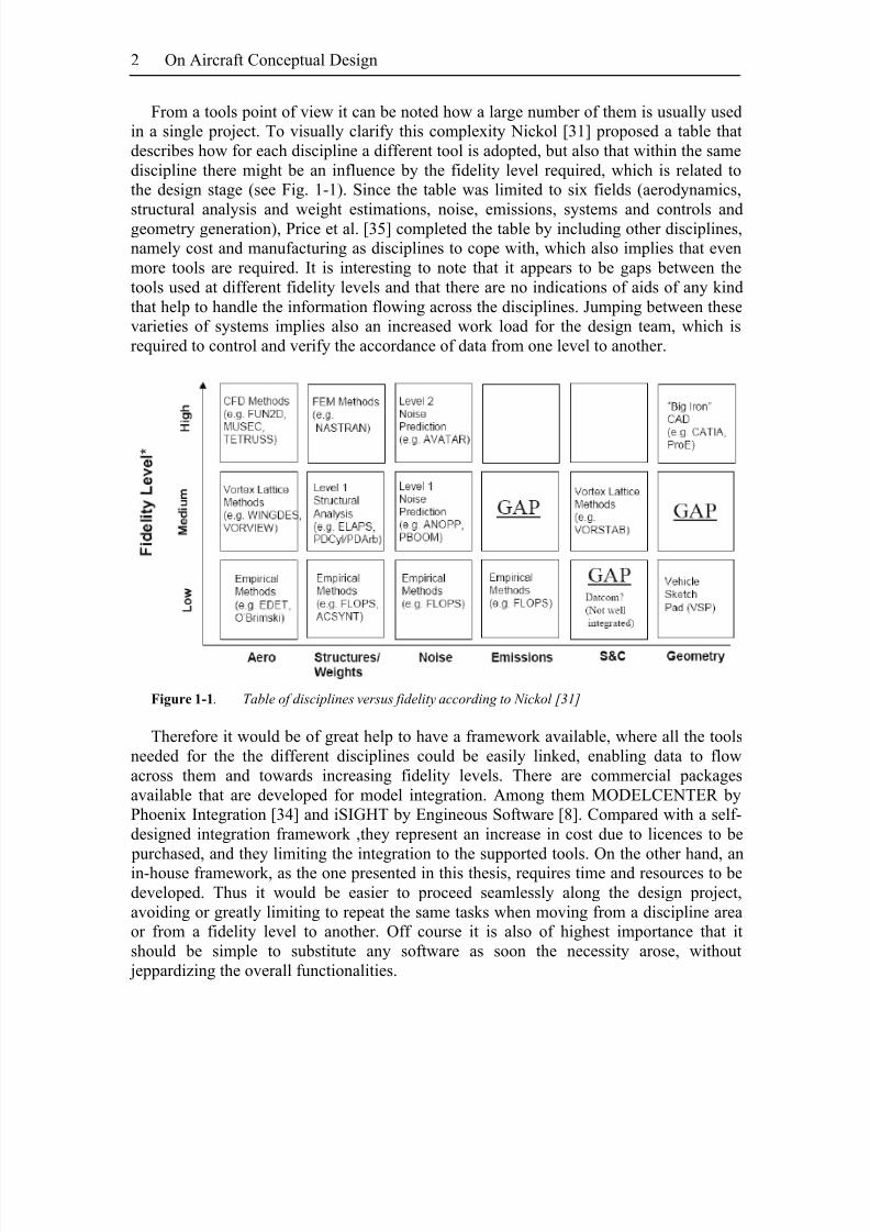
From a tools point of view it can be noted how a large number of them is usually usedin a single project. To visually clarify this complexity Nickol [31] proposed a table thatdescribes how for each discipline a different tool is adopted, but also that within the samediscipline there might be an influence by the fidelity level required, which is related tothe design stage (see Fig. 1-1). Since the table was limited to six fields (aerodynamics,
structural analysis and weight estimations, noise, emissions, systems and controls andgeometry generation), Price et al. [35] completed the table by including other disciplines,namely cost and manufacturing as disciplines to cope with, which also implies that evenmore tools are required. It is interesting to note that it appears to be gaps between thetools used at different fidelity levels and that there are no indications of aids of any kindthat help to handle the information flowing across the disciplines. Jumping between thesevarieties of systems implies also an increased work load for the design team, which isrequired to control and verify the accordance of data from one level to another.
Figure 1-1. Table of disciplines versus fidelity according to Nickol [31]
Therefore it would be of great help to have a framework available, where all the toolsneeded for the the different disciplines could be easily linked, enabling data to flowacross them and towards increasing fidelity levels. There are commercial packagesavailable that are developed for model integration. Among them MODELCENTER byPhoenix Integration [34] and iSIGHT by Engineous Software [8]. Compared with a self-designed integration framework ,they represent an increase in cost due to licences to be purchased, and they limiting the integration to the supported tools. On the other hand, anin-house framework, as the one presented in this thesis, requires time and resources to bedeveloped. Thus it would be easier to proceed seamlessly along the design project,avoiding or greatly limiting to repeat the same tasks when moving from a discipline areaor from a fidelity level to another. Off course it is also of highest importance that itshould be simple to substitute any software as soon the necessity arose, without jeppardizing the overall functionalities.
8/2/2019 K Amadori On Conceptual Aircraft Design
http://slidepdf.com/reader/full/k-amadori-on-conceptual-aircraft-design 17/101
Introduction 3
1.1 Aim and Limitations
With the present work the author intends to propose a novel strategy for the use of high-end tools already from the initial early design stages and to evaluate to which extent the proposed ideas are feasible in a design task. In most cases the first steps in designing a
new aircraft are dominated by the use of very simple low-fidelity empirical or statistical- based models.The key idea is to try to find a way of anticipate the use of complex CAD systems and
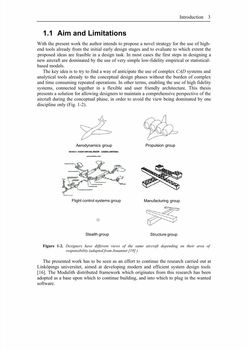
analytical tools already to the conceptual design phases without the burden of complexand time consuming repeated operations. In other terms, enabling the use of high fidelitysystems, connected together in a flexible and user friendly architecture. This thesis presents a solution for allowing designers to maintain a comprehensive perspective of theaircraft during the conceptual phase, in order to avoid the view being dominated by onediscipline only (Fig. 1-2).
Aerodynamics group Propulsion group
Stealth group
Manufacturing groupFlight control systems group
Structure group
Figure 1-2. Designers have different views of the same aircraft depending on their area of responsibility (adapted from Jouannet [19] )
The presented work has to be seen as an effort to continue the research carried out atLinköpings universitet, aimed at developing modern and efficient system design tools[16]. The Modulith distributed framework which originates from this research has beenadopted as a base upon which to continue building, and into which to plug in the wantedsoftware.

8/2/2019 K Amadori On Conceptual Aircraft Design
http://slidepdf.com/reader/full/k-amadori-on-conceptual-aircraft-design 18/101
4 On Aircraft Conceptual Design
Please note that, since the whole concept is still under development, the tools andsystems presented shall not be thought to be ready for a broad industrial deployment or to be offered as a mature and finished product for commercial use.

8/2/2019 K Amadori On Conceptual Aircraft Design
http://slidepdf.com/reader/full/k-amadori-on-conceptual-aircraft-design 19/101
2 Aircraft Design
Fundamentals
CCORDING TO A LARGELY accepted process description [6], [15], [37], [42],aircraft design is usually described as sequence of three different phases:A
- Conceptual Design- Preliminary Design
- Detail Design
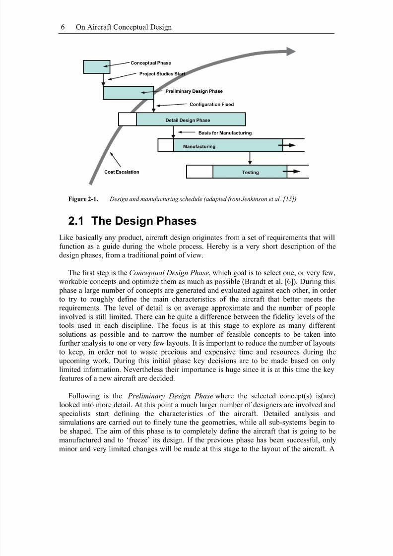
This is the same sequence that is generally adopted design theory [33], [44]. In thischapter a very brief description of the phases will be provided as a theoretical background, together with an overview of the traditional methods and tools that mostoften are adopted during each phase. To some extent, the three phases listed above can becoupled to the three fidelity levels introduced by Nickol in the table in the previouschapter. Figure 2-1 provides a possible graphical representation of the design process.Starting in the top left corner from the conceptual design phase, it can be seen how the phases succeed one another. It is worth noting that overlapping between different phasesis possible in order to greatly shorten the time required to get the product on to the
market. Also important to observe is how the cost increases drastically with time. It isclearly important to avoid large design changes in the later stages when the modificationwould impact on a very large number of components, the human resources involved arevery large and parts have already started being manufactured.
8/2/2019 K Amadori On Conceptual Aircraft Design
http://slidepdf.com/reader/full/k-amadori-on-conceptual-aircraft-design 20/101
On Aircraft Conceptual Design6
Conceptual Phase
Project Studies Start
Preliminary Design Phase
Configuration Fixed
Detail Design Phase
Manufacturing
Basis for Manufacturing
TestingCost Escalation
Figure 2-1. Design and manufacturing schedule (adapted from Jenkinson et al. [15] )
2.1 The Design Phases
Like basically any product, aircraft design originates from a set of requirements that willfunction as a guide during the whole process. Hereby is a very short description of thedesign phases, from a traditional point of view.
The first step is the Conceptual Design Phase, which goal is to select one, or very few,workable concepts and optimize them as much as possible (Brandt et al. [6]). During this
phase a large number of concepts are generated and evaluated against each other, in order to try to roughly define the main characteristics of the aircraft that better meets therequirements. The level of detail is on average approximate and the number of peopleinvolved is still limited. There can be quite a difference between the fidelity levels of thetools used in each discipline. The focus is at this stage to explore as many differentsolutions as possible and to narrow the number of feasible concepts to be taken intofurther analysis to one or very few layouts. It is important to reduce the number of layoutsto keep, in order not to waste precious and expensive time and resources during theupcoming work. During this initial phase key decisions are to be made based on onlylimited information. Nevertheless their importance is huge since it is at this time the keyfeatures of a new aircraft are decided.
Following is the Preliminary Design Phase where the selected concept(s) is(are)looked into more detail. At this point a much larger number of designers are involved andspecialists start defining the characteristics of the aircraft. Detailed analysis andsimulations are carried out to finely tune the geometries, while all sub-systems begin to be shaped. The aim of this phase is to completely define the aircraft that is going to bemanufactured and to ‘freeze’ its design. If the previous phase has been successful, onlyminor and very limited changes will be made at this stage to the layout of the aircraft. A
8/2/2019 K Amadori On Conceptual Aircraft Design
http://slidepdf.com/reader/full/k-amadori-on-conceptual-aircraft-design 21/101
Aircraft Design Fundamentals 7
large amount of people are now allocated to the project. Specialists will carry out analysisand simulations of their respective systems and even some testing can start taking place.Also manufacturing and production planning will be carried out, starting from larger sub-assemblies.
The final step of the design process is the Detail Design Phase during which allcomponents and parts are defined in all their details. It during this phase that all (or atleast most of it) manufacturing documentation is produced. The number of peopleinvolved in this phase can be extremely large and so are the costs. Only aircraft that have been decided to be produced reach this phase. The tools adopted during the detail design phase may not be very different, but they are of highest accuracy, in order to preciselydefine every single aspect of each system. Therefore careful simulations are performedalso at this stage. Clearly it is now very hard to make important changes to the layout of the aircraft. If any mistake was made during the conceptual or preliminary design phase,the aircraft will have to either live with it or in the worst case force the project to becancelled. As an example, the Fairchild T-46A trainer aircraft got cancelled – among
other reasons - after discovering a huge discrepancy in the predicted drag and the valuesmeasured during the test flight campaign, which negatively effected performances [10].
2.2 (Traditional) Tools and Methods
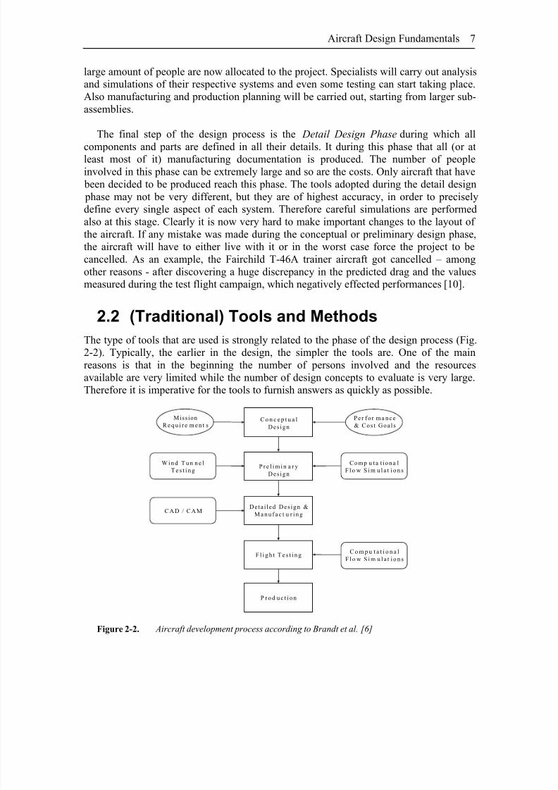
The type of tools that are used is strongly related to the phase of the design process (Fig.2-2). Typically, the earlier in the design, the simpler the tools are. One of the mainreasons is that in the beginning the number of persons involved and the resourcesavailable are very limited while the number of design concepts to evaluate is very large.Therefore it is imperative for the tools to furnish answers as quickly as possible.
Mission
R e q u i r e m e n t sC o n c e p t u a l
Des ign
Per for ma nce
& C os t Goal s
P r e l i m i n a r y
Des ign
Deta i l ed Des ign &
M a n u f a c t u r i n g
F l i g h t T e s t i n g
P r o d u c t i o n
C omp u t a t i ona l
F l o w S i m u l a t i o n s
W i n d T u n n e l
T e s t i n g
C o m p u t a t i o n a lF l o w S i m u l a t i o n s
C AD / C AM
Figure 2-2. Aircraft development process according to Brandt et al. [6]

8/2/2019 K Amadori On Conceptual Aircraft Design
http://slidepdf.com/reader/full/k-amadori-on-conceptual-aircraft-design 22/101
On Aircraft Conceptual Design8
In general, early design analysis is dominated by very simple empirical, semi-empirical or statistical models. Their strength is that they allows for quickly gatheringsignificant information based on extremely limited input. On the other hand, these samemodels can not be very accurate and precise. Moreover, they can show large margin of error if trying to extrapolate answers that fall outside the validity range of the model. For
instance, if using a statistical model to predict the aircraft weight, the result can bemisleading if the model is used to calculate the weight for an aircraft that adopts newmaterials, or new manufacturing technologies or that has an unconventional geometricallayout that is not represented in the population upon which the model is based on.
Computing power has become extremely affordable, and the trend is not going tochange in the future. Already in 1997 Jameson [14] pointed out how times were matureenough for coupling CFD simulations with wind tunnel testing in order to cut time andcosts for the design of new aircraft. He showed that the two methods effectivelycompleted each other. Wind tunnel tests require expensive physical models whosemanufacturing is very time-consuming. Once the model is ready though, several tests indifferent conditions can be quickly carried out. On the other hand, CFD simulations
require long computing time, but there is almost no additional expense for changing themodel. Thus they enable to effectively enlarge the design space. And indeed this thesiswas confirmed in 2005 by Johnson et al. [17]. They presented a review of how CFD had been applied at Boeing Commercial Airplanes during the last thirty years. They showedthat the number of wings tested in wind tunnels was drastically reduced every time a newCFD code was introduced, thus saving huge amounts of money.
It is though very important to note that the same considerations can be made for other tools also. The argumentations just reported are true for the aerodynamic design of anaircraft, but many other fields and disciplines are equally important to successfully designan airplane. This thesis will present a framework through which keeping an overallsystem perspective on the aircraft, where not only one aspect at a time is analyzed.
CAD systems that traditionally are introduced only at later stages can effectively beadopted from the very beginning. The geometrical model will grow in detail level as the project proceeds and will serve as a basis for all analysis to be performed: aerodynamics,structure, costs, manufacturing simulations, weight estimation, on-board systems packingand performance simulations, stability and control. The key issue is to determine how toefficiently couple all disciplines and to find a clever strategy for quickly and easilygenerating CAD models.
8/2/2019 K Amadori On Conceptual Aircraft Design
http://slidepdf.com/reader/full/k-amadori-on-conceptual-aircraft-design 23/101
3 Theory
S PREVIOUSLY DISCUSSED, the design task requires using several differenttools, which needs to be connected. In this work, a novel conceptual design
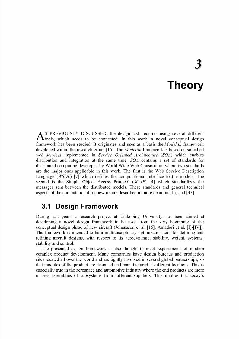
framework has been studied. It originates and uses as a basis the Modelith framework developed within the research group [16]. The Modelith framework is based on so-calledweb services implemented in Service Oriented Architecture (SOA) which enablesdistribution and integration at the same time. SOA contains a set of standards for distributed computing developed by World Wide Web Consortium, where two standardsare the major ones applicable in this work. The first is the Web Service Description
Language (WSDL) [7] which defines the computational interface to the models. Thesecond is the Simple Object Access Protocol (SOAP ) [4] which standardizes themessages sent between the distributed models. These standards and general technicalaspects of the computational framework are described in more detail in [16] and [43].
A
3.1 Design Framework
During last years a research project at Linköping University has been aimed atdeveloping a novel design framework to be used from the very beginning of theconceptual design phase of new aircraft (Johansson et al. [16], Amadori et al. [I]-[IV]).The framework is intended to be a multidisciplinary optimization tool for defining and
refining aircraft designs, with respect to its aerodynamic, stability, weight, systems,stability and control.
The presented design framework is also thought to meet requirements of moderncomplex product development. Many companies have design bureaus and productionsites located all over the world and are tightly involved in several global partnerships, sothat modules of the product are designed and manufactured at different locations. This isespecially true in the aerospace and automotive industry where the end products are moreor less assemblies of subsystems from different suppliers. This implies that today’s
8/2/2019 K Amadori On Conceptual Aircraft Design
http://slidepdf.com/reader/full/k-amadori-on-conceptual-aircraft-design 24/101
10 On Aircraft Conceptual Design
product development is carried out in a distributed, collaborative and competitive fashionand this forms a rather complex environment for the employment of modeling andsimulation technology. These aspects must therefore be supported by the modeling andsimulation tools.
Fuselage
Wing Performance Propulsion
Stability &
Control
Actuation
System
Aerodynamic
s
Fuel System
Electric
Power
System
Fuselage
Wing Performance Propulsion
Actuation
SystemAerodynamics
Fuel System
Electric
Power
System
Aircraft Sizing Model PropulsionStructure
System Model
Optimization
Evaluation
Stability &
Control
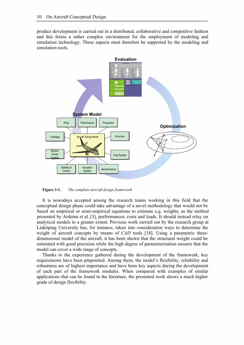
Figure 3-1. The complete aircraft design framework
It is nowadays accepted among the research teams working in this field that theconceptual design phase could take advantage of a novel methodology that would not be based on empirical or semi-empirical equations to estimate e.g. weights, as the method presented by Ardema et al. [3], performances, costs and loads. It should instead relay onanalytical models to a greater extent. Previous work carried out by the research group atLinköping University has, for instance, taken into consideration ways to determine theweight of aircraft concepts by means of CAD tools [18]. Using a parametric three-dimensional model of the aircraft, it has been shown that the structural weight could beestimated with good precision while the high degree of parameterization ensures that themodel can cover a wide range of concepts.
Thanks to the experience gathered during the development of the framework, keyrequirements have been pinpointed. Among them, the model’s flexibility, reliability androbustness are of highest importance and have been key aspects during the developmentof each part of the framework modules. When compared with examples of similar applications that can be found in the literature, the presented work shows a much higher grade of design flexibility.
8/2/2019 K Amadori On Conceptual Aircraft Design
http://slidepdf.com/reader/full/k-amadori-on-conceptual-aircraft-design 25/101
Theory 11
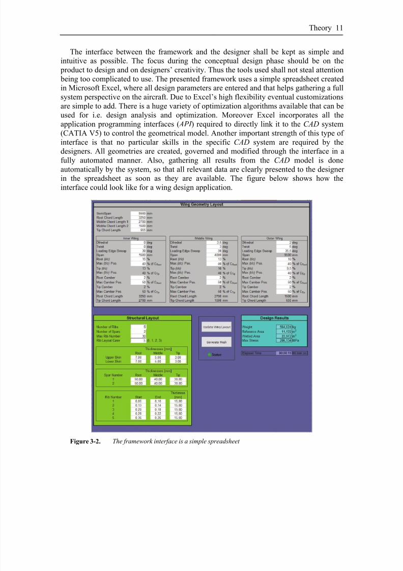
The interface between the framework and the designer shall be kept as simple andintuitive as possible. The focus during the conceptual design phase should be on the product to design and on designers’ creativity. Thus the tools used shall not steal attention being too complicated to use. The presented framework uses a simple spreadsheet createdin Microsoft Excel, where all design parameters are entered and that helps gathering a full
system perspective on the aircraft. Due to Excel’s high flexibility eventual customizationsare simple to add. There is a huge variety of optimization algorithms available that can beused for i.e. design analysis and optimization. Moreover Excel incorporates all theapplication programming interfaces ( API ) required to directly link it to the CAD system(CATIA V5) to control the geometrical model. Another important strength of this type of interface is that no particular skills in the specific CAD system are required by thedesigners. All geometries are created, governed and modified through the interface in afully automated manner. Also, gathering all results from the CAD model is doneautomatically by the system, so that all relevant data are clearly presented to the designer in the spreadsheet as soon as they are available. The figure below shows how theinterface could look like for a wing design application.
Figure 3-2. The framework interface is a simple spreadsheet

8/2/2019 K Amadori On Conceptual Aircraft Design
http://slidepdf.com/reader/full/k-amadori-on-conceptual-aircraft-design 26/101
On Aircraft Conceptual Design12
3.1.1. CATIA and Parametrical Modeling
The most important characteristic of the CAD model is to be highly flexible in order to beable to represent a variety of designs as large as possible. Secondly the model must berobust and reliable, since there will not be a specialist manually entering new parametersand supervising the update process. It is fundamental that the model does not produce
mathematical errors within its whole allowed design range. In order to guarantee a highdegree of flexibility and robustness, the CAD model must be built in a proper way. Figure3-3 shows the relational links between the different elements of the model of a UAV. Theinput parameters govern directly the “Datums Model” ( MDF ) and the “Surfaces Model”( MDS ). The MDF -model is a wireframe model where all reference planes and lines,needed to define the aircraft and its structure, are defined. It is important to notice that allthe structure components in the CAD model depend on both the MDF -model and MDS -model, that depend instead only on the top level input parameters. The MDS surfacesmodel contains all the external surfaces. The structure is obtained by instantiating ageneral structural element that is designed to adapt itself to a specified context, which isspecified in the MDF -model and MDS -model. This general element is used for all the
structure parts of the aircraft: frames, ribs and wing spars. The elements’ geometries aregoverned by individual parameters, allowing for optimization of the structural design,even at a component level.
Figure 3-3. Relationships between elements in the CAD model
All geometries are created in an automated fashion in CATIA. Through thespreadsheet interface the designer decides the general dimension and shape of the aircraftand the number and position of all structural elements. Then the CAD model is updated toreflect the input in the spreadsheet.
To achieve this level of automation the programming possibilities offered by CATIAV5 have been largely taken advantage of. The system allows using several layers of automation and parametrization [24]. With reference to Fig. 3-4 here next, following is adescription of the different approaches, starting from the lowest level.

8/2/2019 K Amadori On Conceptual Aircraft Design
http://slidepdf.com/reader/full/k-amadori-on-conceptual-aircraft-design 27/101
Theory 13
Gen.
Dyn.
Objects
UDFs
Rules &
Reactions
Formulas
Parameters
Fixed Models
Knowledge Based Design
20
10
h = 10
b = 20
h = 10
b = 2*h
b
h
if shape = ”square”
{ h = 10, b = h }
else { h = 10, b = 2*h }b
h
b
h
Patterns
+Script UDF
Figure 3-4. Different levels of parametrization (adapted from Ledermann et al. [24] )
Fixed models are simply geometries where governing parameters or properties (for instance a thickness or a length) can be modified accessing the object containing thegeometry and, searching through the object specifications, manually changing the valueof the parameter of interest.
Parameters of different kind can be adopted to define geometrical characteristics or properties, even outside the object or part. This allows changing the geometry without theneed to actively access the object containing the geometry itself.
Formulas are mathematical relations that link parameters together (for instance the lengthof an object that is required to be a given fraction of the object’s volume). This feature isthe first level that allows incorporating not visible knowledge into the model.
Rules and reactions are more sophisticated ways to include knowledge into the model.Rules are a more general and powerful way to describe relations between all kind of parameters, properties and elements in an object. They are not limited to numerical parameters. Reactions, as the name suggests, allows defining how the model shall react toa given input (for instance a parameter or measure change). Reaction are trigged by theoccurrence of a specified event, while rules are always are always active.
Patterns are used to instantiate features that repeat themselves in the geometry. Keycharacteristic of a pattern is that the feature is repeated always in the exact same way andthere is no chance to modify individually the elements in a pattern. Pattern can bedynamically operated via parameters.

8/2/2019 K Amadori On Conceptual Aircraft Design
http://slidepdf.com/reader/full/k-amadori-on-conceptual-aircraft-design 28/101
On Aircraft Conceptual Design14
UDF s (user defined features) are generally described features that adapt to the context inwhich they are instantiated in the model. They allow each instance to be individuallymodified but are not dynamically governed.
Generic Dynamic Objects are obtained adding scripts to UDF s. In this way UDF s
become dynamically instantiated. Driven by scripts, even highly complex features can beautomatically and dynamically instantiated in the wanted context and they can be givenall the desired characteristics.
3.1.2. Aerodynamic Code: PANAIR
At the moment, the aerodynamic analysis tool adopted is a panel code, PANAIR [26] thatwas developed by The Boeing Company and NASA during the late seventies and earlyeighties to be able to model and simulate complete vehicle configurations. Panel codesare numerical schemes for solving (the Prandtl-Glauert equation) for linear, inviscid,irrotational flow about aircraft flying at subsonic or supersonic speeds (Erikson [9]). As pointed out by Amadori et. al. [I], panel codes are not as precise as modern CFDs can be,
but they have other advantages. Considering that during a conceptual design phase, theaircraft geometry and its outer shape is not precisely defined and that the detail level isquite rough, it is clear that it can be unpractical and not justified to use tools that have amuch higher accuracy. Moreover CFDs requires the space around the studied body to beaccurately meshed, while for a panel code it is sufficient to approximate the aircraft’souter surfaces with proper rectangular panels. Therefore the meshing time required by a panel code is lower by several orders of magnitude, compared to a CFD code. It should be kept in mind that, in this framework, PANAIR is used mainly to compare theeffectiveness of different concepts with each other, rather than to gather exact andabsolute figures of their aerodynamic efficiency. When more powerful and faster computers will be available or if higher accuracy was required, PANAIR could be
substituted with other solvers, thanks to the modular nature of the framework.The data that is gathered from the panel code analysis are the lift coefficient (c L),calculated using Trefftz plane analysis, the induced drag coefficient (c Di) and the pitchingmoment coefficient (cm) and thus the aerodynamic forces and moments acting on theairplane.
The upper and lower surfaces of the wing are meshed with rectangular panels using anin-house developed meshing application. This application is based on a set of script- procedures that can be activated from the spreadsheet interface and that also handles allsteps required for starting the aerodynamic analysis. The surfaces are at first split alongthe front and aft spars. This is done to simplify the aerodynamic loads retrievingoperations. This is done because PANAIR presents results for each surface separately and
then assembled for the whole aircraft. Since only the load-carrying structure is analyzed,the air loads coming from the forward and aft surfaces are then simply applied along thefront and rear spars.
8/2/2019 K Amadori On Conceptual Aircraft Design
http://slidepdf.com/reader/full/k-amadori-on-conceptual-aircraft-design 29/101
Theory 15
External Aircraft Shape(CAD)
Aerodynamics(PANAIR)
FEM Analysis Structural Layout
OptimizationAlgorithm
Design Parameters
Structure Optimization
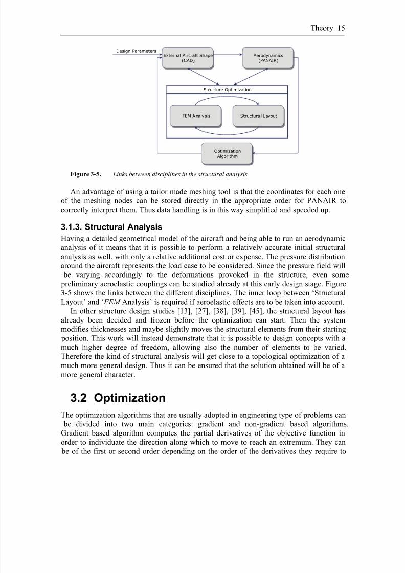
Figure 3-5. Links between disciplines in the structural analysis
An advantage of using a tailor made meshing tool is that the coordinates for each one
of the meshing nodes can be stored directly in the appropriate order for PANAIR tocorrectly interpret them. Thus data handling is in this way simplified and speeded up.
3.1.3. Structural Analysis
Having a detailed geometrical model of the aircraft and being able to run an aerodynamicanalysis of it means that it is possible to perform a relatively accurate initial structuralanalysis as well, with only a relative additional cost or expense. The pressure distributionaround the aircraft represents the load case to be considered. Since the pressure field will be varying accordingly to the deformations provoked in the structure, even some preliminary aeroelastic couplings can be studied already at this early design stage. Figure3-5 shows the links between the different disciplines. The inner loop between ‘Structural
Layout’ and ‘ FEM Analysis’ is required if aeroelastic effects are to be taken into account.In other structure design studies [13], [27], [38], [39], [45], the structural layout has
already been decided and frozen before the optimization can start. Then the systemmodifies thicknesses and maybe slightly moves the structural elements from their starting position. This work will instead demonstrate that it is possible to design concepts with amuch higher degree of freedom, allowing also the number of elements to be varied.Therefore the kind of structural analysis will get close to a topological optimization of amuch more general design. Thus it can be ensured that the solution obtained will be of amore general character.
3.2 OptimizationThe optimization algorithms that are usually adopted in engineering type of problems can be divided into two main categories: gradient and non-gradient based algorithms.Gradient based algorithm computes the partial derivatives of the objective function inorder to individuate the direction along which to move to reach an extremum. They can be of the first or second order depending on the order of the derivatives they require to
8/2/2019 K Amadori On Conceptual Aircraft Design
http://slidepdf.com/reader/full/k-amadori-on-conceptual-aircraft-design 30/101
On Aircraft Conceptual Design16
calculate to define the search direction [32]. These algorithms are fast but usually notquite able to avoid stopping at local extrema, in case of non-convex functions.
The other family of algorithms, the non-gradient based ones, as the name suggests, donot use gradients for searching for extremum in the objective function. This couldrepresent an advantage in those optimization problems where the objective function is
obtained from both simulation results and analytical calculation, thus making it hard toextract the derivatives [1]. The techniques involved in these algorithms are various. Theycan use ‘Random Search’, where the design space is searched randomly. An alternative is‘Hooke and Jeeves Method’ that “is based on a sequence of exploratory and patternmoves” [32] to explore the surroundings of a given point in the solution space. Other methods try to emulate natural or biological systems to try to reach to the objectivefunction’s extremum. To this category belong the ‘Genetic Algorithms’, the ‘Ant ColonyOptimization’ or the ‘Swarm Optimization’. Other algorithms are the ‘Simplex Method’[30], [41] and the ‘Complex Method’ [5], [12] that use geometric shapes to decide thesearch direction starting from a given point in the space. Non-gradient based methods can be aggravated by heavier computational expenses required to reach to a solution, but are
capable of handling also non-convex objective functions without ending up in a localoptimum as a gradient method would do. Here below is a brief description of thealgorithms that have been used in this work.
3.2.1. Fmincon
The method originates from Wilson in 1963 and was first implemented by Pschenichny(1970) and Han (1977). According to Onwubiko [32], the popularity of the method relayson its capability of finding the optimum solution starting from an arbitrary point in thedesign space. Moreover Fmincon requires less function evaluations compared with other algorithms suited for constrained optimization problems.
Fmincon is an optimization algorithm that can be found in MatLab’s Optimization
Toolbox. Quoting the documentation accompanying the algorithm itself, it is aconstrained nonlinear optimizer that uses the second order gradient method SequentialQuadratic Programming (SQP) to find a constrained minimum of a scalar function of several variables starting at an initial estimate.
3.2.2. Complex
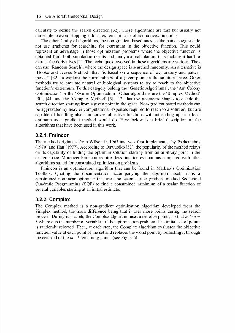
The Complex method is a non-gradient optimization algorithm developed from theSimplex method, the main difference being that it uses more points during the search process. During its search, the Complex algorithm uses a set of m points, so that m ≥ n +1 where n is the number of variables of the optimization problem. The initial set of pointsis randomly selected. Then, at each step, the Complex algorithm evaluates the objective
function value at each point of the set and replaces the worst point by reflecting it throughthe centroid of the m - 1 remaining points (see Fig. 3-6).
8/2/2019 K Amadori On Conceptual Aircraft Design
http://slidepdf.com/reader/full/k-amadori-on-conceptual-aircraft-design 31/101
Theory 17
Figure 3-6. The complex algorithm reflects the worst point through the centroid of the remaining
points
The Complex algorithm can also be tuned using the tolerance for function and
parameters convergence. A modified version called Complex-RF [21] introduced alsotwo more parameters, the so called “forgetting factor” and “randomization factor”. Thelatter parameters are used to increase the robustness of the method. The first one ensuresthat the older points in the complex are neglected, which is useful if the objectivefunction changes over time. The randomization factor adds a random noise vector to thenew point being calculated. Thus the algorithm is made less prone to prematurelycollapse on local optima, at the expense of an increased time required to get toconvergence.
3.2.3. Genetic Algorithm
Genetic algorithms are mathematical schemes that try to replicate the natural selection process to search the extremum of the objective function. Each possible solution or pointin the n-dimensional design space is represented by an individual whose n genescorrespond to the n design parameters. Genes can be coded as numbers, strings or bits,depending on the nature of the problem. To be able to carry out the optimization thealgorithm requires a population of individuals to be initially defined. The idea is then tomate the best individual in the population generating new individuals that are hopefullyeven better than their parents. There are several mechanisms through which the matingcan be performed, as well as there are different ways to eliminate the overflowingindividuals from the population, whose size is kept constant through the optimization. Itis even possible to define mutation factors that randomly change some genes during thecreation of new individuals, which increases the algorithm robustness and capability of
exploring the whole space searching for the true optimum.The strength of genetic algorithms is that they are able to locate the optimal solution
even in problems that do not possess well-behaved objective functions. On the other handthey usually are computationally heavy, requiring to evaluate the objective function for each individual at every generation. Onwubiko [32] suggests population sizes between 20and 100 individuals, depending on the number of optimization variables involved.Clearly, large population implies longer time to get to convergence, due to the larger number of objective function evaluations.

8/2/2019 K Amadori On Conceptual Aircraft Design
http://slidepdf.com/reader/full/k-amadori-on-conceptual-aircraft-design 32/101
On Aircraft Conceptual Design18
8/2/2019 K Amadori On Conceptual Aircraft Design
http://slidepdf.com/reader/full/k-amadori-on-conceptual-aircraft-design 33/101
4 Proposed Conceptual
Design Process
HIS CHAPTER DESCRIBES how the conceptual design framework has evolved to be used in several design projects, in order to test the validity of the tool itself as well
as trying to verify its effectiveness in a given design task. As described in the previouschapter, the framework will include analysis tools to cover all the required disciplinesthat are involved during the conceptual design phase. It has also been described how the
framework has been designed to guarantee flexibility and platform independence, so thattools can be linked and removed without harming the overall functionalities. Withreference to the appended papers [I], [II], [III], in the following sections it will beexplained how tools for aerodynamic analysis, optimization, geometry generation andstructural analysis have been successively included and tested in the framework.
T
4.1 Panel Code and Optimization Algorithms
In order to be able to predict the aircraft’s performances it is required to analyze itsaerodynamics. As a very first step this means trying to estimate how much lift and drag
its shape will generate when flying in different conditions. During the initial design phases designers have to cope with very basic issues regarding the aircraft’s layout andshape, while more detailed investigations and fine tuning of details will be carried outonly during later stages.
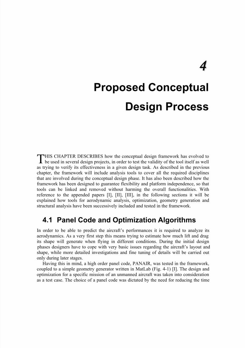
Having this in mind, a high order panel code, PANAIR, was tested in the framework,coupled to a simple geometry generator written in MatLab (Fig. 4-1) [I]. The design andoptimization for a specific mission of an unmanned aircraft was taken into considerationas a test case. The choice of a panel code was dictated by the need for reducing the time
8/2/2019 K Amadori On Conceptual Aircraft Design
http://slidepdf.com/reader/full/k-amadori-on-conceptual-aircraft-design 34/101
On Aircraft Conceptual Design20
required to perform an analysis. It can be argued that CFD codes have much higher accuracy, but the time they required is at least an order of magnitude higher. Moreover they require the three-dimensional space around the aircraft to be accurately meshed,while a panel code only needs the wetted surface to be meshed. Moreover, panel codesare much more forgiving in terms of meshing accuracy.
Opt_Panair.m
InputPanair.m
OptIndata.m
Panair
Complexrf(parameters)Objective Function
Aerodata
Actual parameters
Panair Input File
Figure 4-1. Actual dataflow in the framework for testing PANAIR [I]
The aim was to test PANAIR and evaluate different optimization algorithms.Therefore all the other tools and disciplines required where “simulated” in the framework using simpler rules of thumb, empirical equations or statistically based formulas takenfrom the literature [6], [15], [37], [42]. Hence the scheme shown in Fig. 4-1 onlymarginally resembles what is pictured in Fig. 3-1 in Chapter 3.
The biggest drawback of using a panel code is that it can not take into considerationviscous effects, but only information regarding the induced drag are given. That meansthat the other drag components need to be estimated in other ways. What has been doneso far is to use well known approximated formulas, with inputs as precise as the toolsadopted allows. For instance, the parasite drag is calculated as:
ref
wet fed
S
S cC ⋅=0 (4.1)
where c fe is an “equivalent skin friction coefficient” that can be found in tables as the onereported by Raymer [37]. If using precise CAD tools for representing the geometry of the
aircraft, both S wet and S ref will be exactly known.Even with these drawbacks and even if other types of aerodynamic codes could
produce more precise results, it must be remembered that the main goal is to test the useof an analytical tool for initial aerodynamic estimation rather than trying to find the toolthat promises to achieve the best “precision-to-performance” ratio. Keeping this in mind, panel codes are perfectly suitable for the challenge. They are able to analyze virtually anytype of three-dimensional geometry, they produce significant results and, very important,they are fast.
8/2/2019 K Amadori On Conceptual Aircraft Design
http://slidepdf.com/reader/full/k-amadori-on-conceptual-aircraft-design 35/101
Proposed Conceptual Design Process 21
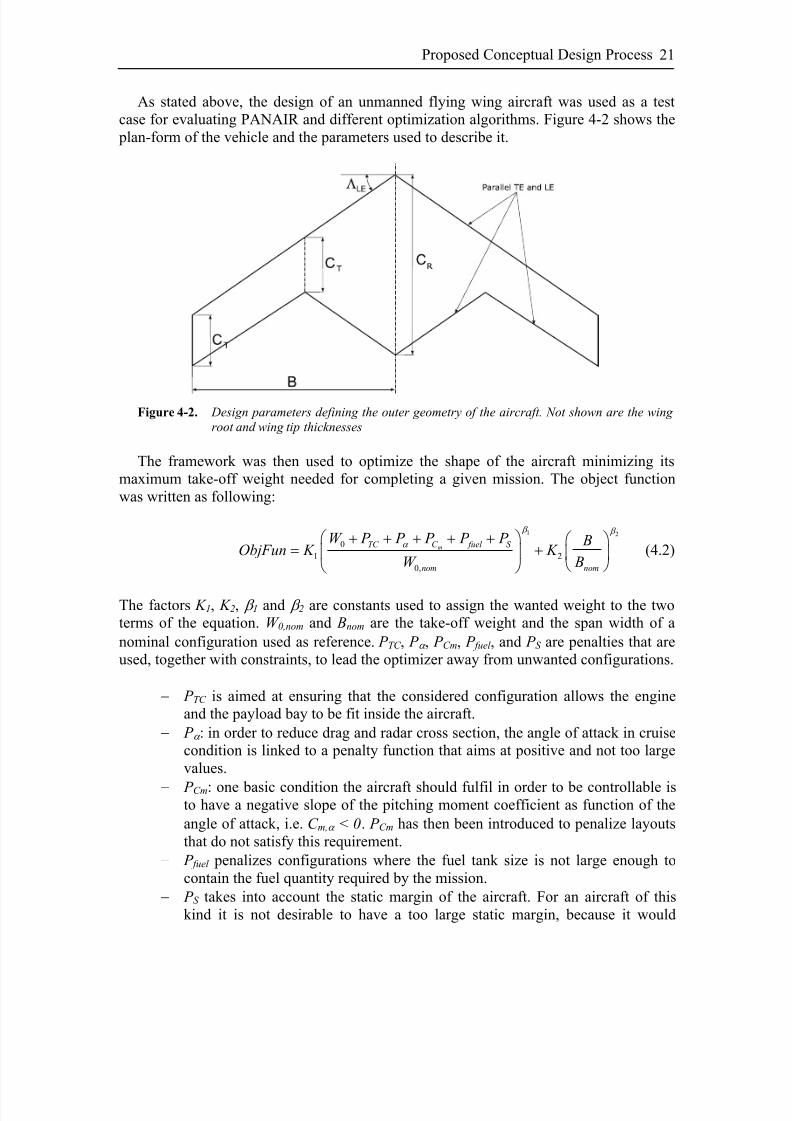
As stated above, the design of an unmanned flying wing aircraft was used as a testcase for evaluating PANAIR and different optimization algorithms. Figure 4-2 shows the plan-form of the vehicle and the parameters used to describe it.
Figure 4-2. Design parameters defining the outer geometry of the aircraft. Not shown are the wing
root and wing tip thicknesses
The framework was then used to optimize the shape of the aircraft minimizing itsmaximum take-off weight needed for completing a given mission. The object functionwas written as following:
1 2
0
1 2
0,
mTC C fuel S
nom nom
W P P P P P BObjFun K K
W B
β β
α ⎛ ⎞+ + + + + ⎛ ⎞
= +⎜ ⎟ ⎜ ⎟⎝ ⎠⎝ ⎠
(4.2)
The factors K 1, K 2, β 1 and β 2 are constants used to assign the wanted weight to the twoterms of the equation. W 0,nom and Bnom are the take-off weight and the span width of anominal configuration used as reference. P TC , P α , P Cm, P fuel , and P S are penalties that areused, together with constraints, to lead the optimizer away from unwanted configurations.
− P TC is aimed at ensuring that the considered configuration allows the engineand the payload bay to be fit inside the aircraft.
− P α : in order to reduce drag and radar cross section, the angle of attack in cruisecondition is linked to a penalty function that aims at positive and not too largevalues.
− P Cm: one basic condition the aircraft should fulfil in order to be controllable isto have a negative slope of the pitching moment coefficient as function of theangle of attack, i.e. C m,α < 0. P Cm has then been introduced to penalize layoutsthat do not satisfy this requirement.
− P fuel penalizes configurations where the fuel tank size is not large enough tocontain the fuel quantity required by the mission.
− P S takes into account the static margin of the aircraft. For an aircraft of thiskind it is not desirable to have a too large static margin, because it would

8/2/2019 K Amadori On Conceptual Aircraft Design
http://slidepdf.com/reader/full/k-amadori-on-conceptual-aircraft-design 36/101
On Aircraft Conceptual Design22
require large trim-deflections of the control surfaces. The aircraft could thenresult hardly controllable since the surfaces may not be able to be deflectedenough before they reach the end position. Therefore it is usual to strivetowards small static margins and then relay on the control system.
The optimization problem was formulated as following:
min max
.
.
, .
min max
min max
min
. .
0
. . . . . .
req
req
eff eff all
m
cruise
ObjFun
s t
x x x
R R
E E
c
S M S M S M
α
σ σ
α α α
≤ ≤
≥
≥
≤
<
< << <
(4.3)
Three different optimization algorithms were tried: Fmincon, Complex and a GeneticAlgorithm (GA). What resulted clearly from the test was that Fmincon, which is based ona gradient based method, was most often unsuccessful in solving the problem, stoppingthe optimization as soon as it reached to a local extremum of the solution space. TheComplex algorithm and the GA were instead both able to correctly solve the optimization problem, but showing different performances. To evaluate the two algorithms’ performances a so called “performance index” was used [20], calculated as following:
2,
(1 )opt
obj opt
m
Log P f
k
−= − (4.4)
where P opt is the probability of finding the optimum and k m is the number of iterationsrequired. The results are summarized in the table below.
Parameter t R t T ΛLE C R C T B ρ WMTOW f obj,opt
Complex 20 % 8.13 % 44.2º 13.49m 4.17m 5.99m 2.56º 18,716 kg 5.6·10-4
GA 20 % 8.15 % 44.11º 13.50m 4.21m 6.00 m 2.20º 18,656 kg 5.0·10-4
Table 4-1. Optimization results for the Complex and the Genetic Algorithms
As the table shows, the two algorithms showed almost the same performance index.The Complex-RF algorithm did find the correct solution one third of the times it was run,while the GA registered a hit rate of about 75%, but to do so it required three times as

8/2/2019 K Amadori On Conceptual Aircraft Design
http://slidepdf.com/reader/full/k-amadori-on-conceptual-aircraft-design 37/101
Proposed Conceptual Design Process 23
many objective function evaluations when compared to the Complex-RF, which makesthem roughly comparable.
4.2 CAD Modeling
In order to be able to achieve true multidisciplinary design analysis and optimization it is beneficial to use the same geometrical data as source for all disciplines involved [24].This means that the CAD model assumes a very central role in the framework. Not only ithas to contain all information that is required for all disciplines to carry out their analysis, but it also has to guarantee a degree of flexibility high enough to cover the widest possible range of different configurations. The cost and the time required to create amodel with the characteristics described in section 3.1.1 is inevitably higher than for aconventional model. On the other hand, a parametric and associative model ensures that,within its validity range, all configurations and variants are covered and represented, sothat the same model can be reused saving time and money. Ledermann et al. [24] presented a graph (reported herby in Fig. 4-3) that highlights these differences. It showed
that, during the initial phases of the design of a new aircraft, a highly flexible parametricmodel will cost more, but that, as time goes on, the total cost becomes lower. This is also because in an aircraft design there are many repetitive features that such a model enablesreusing instead of repeatedly recreating them. Moreover, the cost of a parametric modelcan be split over several projects, if its flexibility allows reusing it. The major problem isto identify the level of parametrization and automation that is required for a given projectand that represent the right balance between built-in functionalities and cost.
Design Expanditures
Feasibility
Phase
Concept
Phase
Design
Phase
Production
Phase
Parametric
Associative Design
Conventional
Design
Figure 4-3. Design expanditures in an aircraft design project (Ledermann et al.[24] )
The CAD model created for the framework application was intended to meet fivespecific requirements:
1. to include the outer surfaces of a flying wing type of aircraft or of a wing of aconventional aircraft;
2. to include the main structural elements such as frames, ribs and spars;3. to guarantee high flexibility so that both the external shape and the internal
structure layout can be changed as wanted;

8/2/2019 K Amadori On Conceptual Aircraft Design
http://slidepdf.com/reader/full/k-amadori-on-conceptual-aircraft-design 38/101
On Aircraft Conceptual Design24
4. to be operated from an Excel spreadsheet so that no knowledge of the CAD system would be required by the designer;
5. to allow for design optimization and automation.
The external surfaces were parametrized in the same way as in the test case described
in the previous section. They are obtained sweeping a surface using the wing airfoilcontours as profiles and the leading and trailing edge as guide lines. The choice of theairfoil mathematical representation is critical to ensure a wide range of usage. Thereforethe wing profiles were using the formulation suggested by Kulfan and Bussoletti [22] (seealso Fig. 4-4):
(4.5)
( ) ( ) ( )
( ) ( ) ( )
1
1
n
i i Upper Upper i
n
i i Lower Lower i
C Au S
C Al S
ξ ψ ψ ψ
ξ ψ ψ ψ ξ
=
=
⎛ ⎞= ⋅ ⋅ + ⋅ Δ⎜ ⎟
⎝ ⎠
⎛ ⎞= ⋅ ⋅ + ⋅ Δ⎜ ⎟
⎝ ⎠
∑
∑
ξ
where: zc
ξ = is the non-dimensional airfoil ordinate;
z is the profile coordinate along the z-axis; x
cψ = is the non-dimensional airfoil station;
x is the profile coordinate along the x-axis;
is the “class function”;( ) ( ) 21 1 N N C ψ ψ ψ = ⋅ −
( )iS ψ is the ith-term of the Bernstein polynomial of order n;
TE Upper
zu
cξ Δ = is the non-dimensional upper surface trailing edge thickness ratio;
TE Lower
zl
cξ Δ = is the non-dimensional lower surface trailing edge thickness ratio;
Al i, Aui, N 1 and N 2 are coefficients to be determined to obtain the wanted shape.
c
zuTE
zl TE
x
z
Figure 4-4. General representation of a blunt base / round nose airfoil
The strength of this formulation relies on its capability of representing any smooth airfoilwith any required accuracy level. The smoothness is guaranteed by the formulation itself,

8/2/2019 K Amadori On Conceptual Aircraft Design
http://slidepdf.com/reader/full/k-amadori-on-conceptual-aircraft-design 39/101
Proposed Conceptual Design Process 25
while the precision with which the airfoil is represented depends on the order of theBernstein polynomial. It is also possible to represent with good precision even sharp-nose profiles, which is favorable when dealing with certain type of aircraft, that for instancehave stealth requirements.
The CAD model enabled to modify the position of every single structural element as
well as the number of elements. If new elements need to be added, using general dynamicobjects (described in section 3.1.1), the system instantiates the parts where specified. It isimportant to notice that during this operation all required links to the references objects inthe model are established so that the hierarchical product structure is respected andmaintained. This is mandatory in order to preserve the operability of the model and itslevel of flexibility. Moreover it ensures that, later on, each part of the model can bereadily used during the upcoming preliminary and detail design phases, without needingto rebuild any object. Details can be added to each part of the product assembly, stillmaintaining the correct links to the references. Figure 4-4 shows the CAD model of theaircraft.
Figure 4-5. Parametric CAD model of an aircraft
Represented are the external surfaces, the engine with its air intake and exhaustchannels, and a tentative structure composed by upper and lower skins, fuselage framesand wing spars and ribs. All structural elements are characterized by a rectangular cross-section whose thickness can be individually varied through a specific parameter. Theelements location and number are depending on the MDF -reference as previouslyexplained in chapter 3.
To simplify the aircraft structure modeling task, all structure elements are instantiatedfrom the very same reference object using the so called Functional Molded Parts ( FMP ). FMP is a product available in CATIA V5 that was initially thought to ease molded, castand forget parts. FMP features are history-free, meaning that the order in whichoperations are performed does not affect the end result. Instead they allow for functionalspecification of operations and references. An example will help to explain. Some of theelements require to be cut out to make room for the payload bay or the channel where toinstall the engine, air intake and exhaust. Using FMP they can be defined as protectedvolumes, meaning that an element is cut if it intersects one of the specified regions (Fig.4-6). This way lot of time is saved, since it is not necessary to include any additional

8/2/2019 K Amadori On Conceptual Aircraft Design
http://slidepdf.com/reader/full/k-amadori-on-conceptual-aircraft-design 40/101
On Aircraft Conceptual Design26
control on weather the protected regions are violated or not, nor is it necessary to design parameters-regulated cut outs in the structural elements. Of course, FMP allows for further detailing the parts if and when required.
Figure 4-6. The structural elements are all instantiated from a general part using Functional Molded
Parts (FMP)
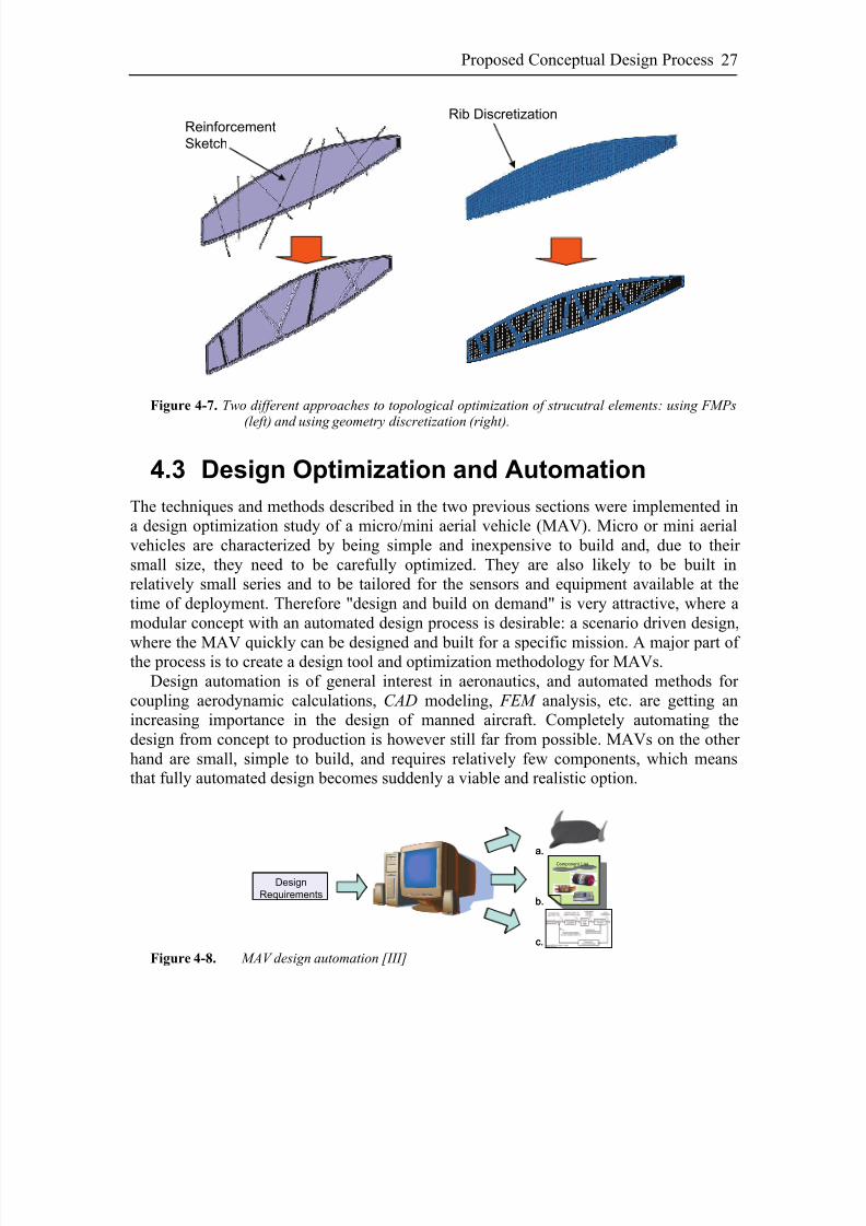
Acquiring the loads working on each part, a new local optimization could be started todistribute all reinforcements on the part. This would resemble a topological optimizationof the structural element, not too different from the wing rib optimization presented byMaute et al. [28]. In their work, they discretized the rib using small “pixels” that the
optimization algorithm could later keep or discard, in order to minimize the weight.Using FMP s, reinforcement ribs can be defined starting from a simple sketch that issuperimposed on a given solid geometry. By using this type of approach, the optimizationalgorithm would be used to draw the sketch, by choosing the number, position anddirection of each line that is then used as reference for the reinforcement ribs (Fig. 4-7).The same technique adopted for the rib and spars placement can be implemented todescribe and optimize the reinforcement sketch.
The result is an extremely flexible and robust model. Not only the outer shape can bemodified as wished through a set of global parameters, but also its internal structurelayout will follow accordingly, thanks to the hierarchical and associative nature of themodel. All changes are trigged and governed by editing an Excel spreadsheet that is
connected to the model. Therefore a designer does not require any knowledge of the CAD system to proficiently operate it and beneficiate of it. Least but not last, the use of aspreadsheet to control the geometry helps maintaining a broader system overview of thewhole vehicle.
8/2/2019 K Amadori On Conceptual Aircraft Design
http://slidepdf.com/reader/full/k-amadori-on-conceptual-aircraft-design 41/101
Proposed Conceptual Design Process 27
Reinforcement
Sketch
Rib Discretization
Figure 4-7. Two different approaches to topological optimization of strucutral elements: using FMPs(left) and using geometry discretization (right).
4.3 Design Optimization and Automation
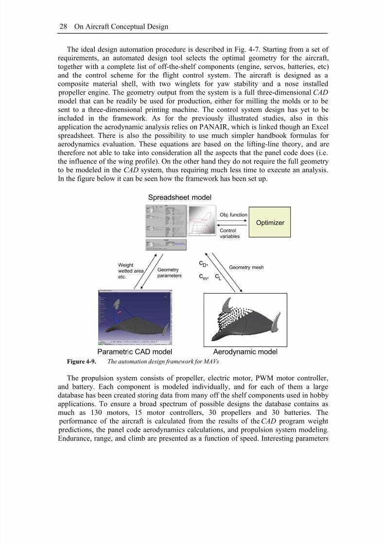
The techniques and methods described in the two previous sections were implemented ina design optimization study of a micro/mini aerial vehicle (MAV). Micro or mini aerialvehicles are characterized by being simple and inexpensive to build and, due to their small size, they need to be carefully optimized. They are also likely to be built inrelatively small series and to be tailored for the sensors and equipment available at thetime of deployment. Therefore "design and build on demand" is very attractive, where amodular concept with an automated design process is desirable: a scenario driven design,
where the MAV quickly can be designed and built for a specific mission. A major part of the process is to create a design tool and optimization methodology for MAVs.Design automation is of general interest in aeronautics, and automated methods for
coupling aerodynamic calculations, CAD modeling, FEM analysis, etc. are getting anincreasing importance in the design of manned aircraft. Completely automating thedesign from concept to production is however still far from possible. MAVs on the other hand are small, simple to build, and requires relatively few components, which meansthat fully automated design becomes suddenly a viable and realistic option.
Design
Requirements
a.
b.
c.
Component List
Component List
Design
Requirements
a.
b.
c.
Component List
Component List
Component List
Component List
Figure 4-8. MAV design automation [III]
8/2/2019 K Amadori On Conceptual Aircraft Design
http://slidepdf.com/reader/full/k-amadori-on-conceptual-aircraft-design 42/101
On Aircraft Conceptual Design28
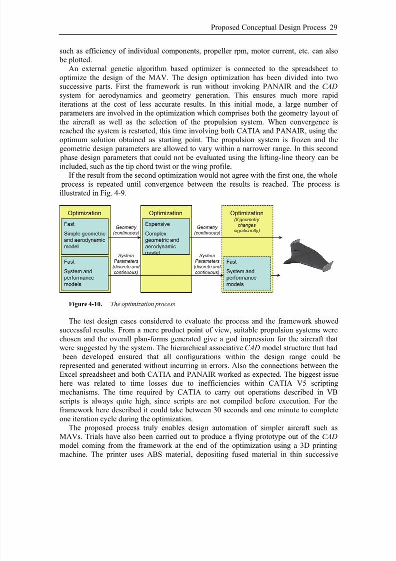
The ideal design automation procedure is described in Fig. 4-7. Starting from a set of requirements, an automated design tool selects the optimal geometry for the aircraft,together with a complete list of off-the-shelf components (engine, servos, batteries, etc)and the control scheme for the flight control system. The aircraft is designed as acomposite material shell, with two winglets for yaw stability and a nose installed
propeller engine. The geometry output from the system is a full three-dimensional CAD model that can be readily be used for production, either for milling the molds or to besent to a three-dimensional printing machine. The control system design has yet to beincluded in the framework. As for the previously illustrated studies, also in thisapplication the aerodynamic analysis relies on PANAIR, which is linked though an Excelspreadsheet. There is also the possibility to use much simpler handbook formulas for aerodynamics evaluation. These equations are based on the lifting-line theory, and aretherefore not able to take into consideration all the aspects that the panel code does (i.e.the influence of the wing profile). On the other hand they do not require the full geometryto be modeled in the CAD system, thus requiring much less time to execute an analysis.In the figure below it can be seen how the framework has been set up.
Weight
wetted area
etc.
Geometry
parameters
Optimizer
Obj. function
Control
variables
Parametric CAD model Aerodynamic model
Spreadsheet model
Geometry meshcD,
cm, cL
Figure 4-9. The automation design framework for MAVs
The propulsion system consists of propeller, electric motor, PWM motor controller,and battery. Each component is modeled individually, and for each of them a largedatabase has been created storing data from many off the shelf components used in hobbyapplications. To ensure a broad spectrum of possible designs the database contains asmuch as 130 motors, 15 motor controllers, 30 propellers and 30 batteries. The performance of the aircraft is calculated from the results of the CAD program weight predictions, the panel code aerodynamics calculations, and propulsion system modeling.Endurance, range, and climb are presented as a function of speed. Interesting parameters
8/2/2019 K Amadori On Conceptual Aircraft Design
http://slidepdf.com/reader/full/k-amadori-on-conceptual-aircraft-design 43/101
Proposed Conceptual Design Process 29
such as efficiency of individual components, propeller rpm, motor current, etc. can also be plotted.
An external genetic algorithm based optimizer is connected to the spreadsheet tooptimize the design of the MAV. The design optimization has been divided into twosuccessive parts. First the framework is run without invoking PANAIR and the CAD
system for aerodynamics and geometry generation. This ensures much more rapiditerations at the cost of less accurate results. In this initial mode, a large number of parameters are involved in the optimization which comprises both the geometry layout of the aircraft as well as the selection of the propulsion system. When convergence isreached the system is restarted, this time involving both CATIA and PANAIR, using theoptimum solution obtained as starting point. The propulsion system is frozen and thegeometric design parameters are allowed to vary within a narrower range. In this second phase design parameters that could not be evaluated using the lifting-line theory can beincluded, such as the tip chord twist or the wing profile.
If the result from the second optimization would not agree with the first one, the whole process is repeated until convergence between the results is reached. The process is
illustrated in Fig. 4-9.
Optimization
Fast
Simple geometric
and aerodynamic
model
Fast
System and
performance
models
Optimization
Expensive
Complex
geometric and
aerodynamic
model
Optimization
Fast
System and
performance
models
Geometry
(continuous)
Geometry
(continuous)
System
Parameters
(discrete and
continuous)
System
Parameters
(discrete and
continuous)
(If geometry
changessignificantly)
Figure 4-10. The optimization process
The test design cases considered to evaluate the process and the framework showedsuccessful results. From a mere product point of view, suitable propulsion systems werechosen and the overall plan-forms generated give a god impression for the aircraft thatwere suggested by the system. The hierarchical associative CAD model structure that had been developed ensured that all configurations within the design range could berepresented and generated without incurring in errors. Also the connections between theExcel spreadsheet and both CATIA and PANAIR worked as expected. The biggest issuehere was related to time losses due to inefficiencies within CATIA V5 scripting
mechanisms. The time required by CATIA to carry out operations described in VBscripts is always quite high, since scripts are not compiled before execution. For theframework here described it could take between 30 seconds and one minute to completeone iteration cycle during the optimization.
The proposed process truly enables design automation of simpler aircraft such asMAVs. Trials have also been carried out to produce a flying prototype out of the CAD model coming from the framework at the end of the optimization using a 3D printingmachine. The printer uses ABS material, depositing fused material in thin successive

8/2/2019 K Amadori On Conceptual Aircraft Design
http://slidepdf.com/reader/full/k-amadori-on-conceptual-aircraft-design 44/101
On Aircraft Conceptual Design30
layers, as thin as 0,17 mm, which gives a quite good surface definition and smoothness[36]. The only operation left on the model once printed is eventually to quickly sandaway small imperfections on the surface and to install the electronic components. Theresulting aircraft is heavier than what could be achieved by using composite materials, but the practicality of the 3D printing method is unbeatable for this type of application.
Using composite materials that require molds imply a much longer production time and acapital investment that may not be justified if the amount of aircraft to produce is small.For 3D printing, on the other hand, only acquiring a printer is needed to be able to produce an infinite number of different MAVs.
8/2/2019 K Amadori On Conceptual Aircraft Design
http://slidepdf.com/reader/full/k-amadori-on-conceptual-aircraft-design 45/101
5 Discussion and
Conclusions
ATIONALIZATION OF THE design process and introduction of multidisciplinaryoptimization are no novel topics in aircraft design. In the literature there are
examples that can be tracked back to the early seventies [11], emphasizing how the needand the benefits have been known for a very long time. On the other hand, much fewer are the cases in which systems, techniques and tools have been used successful on alarger scale. It is not uncommon that limited and tailor made applications have been
adopted, but rarely the same solution is suitable for different tasks, or different problems,or, even harder, different companies. The main reason for this being that in most casesthese multidisciplinary optimizations cope with very specific applications, wheredifferent software are connected by means of non-standard interfaces, or where even in-house codes are involved. The problem that is analyzed may also be very companyrelated.
R
What has been proposed in this thesis is a framework architecture that focuses on itsflexibility of application. The main goal is not to provide with a commercial tool ready to be installed and use, but to present a roadmap and a description of how amultidisciplinary environment can be efficiently set up to solve design optimization problems. There are several commercial products that enable design process automation
(MODELCENTER, iSIGHT,…). These software will inevitably introduce compatibilitylimitations and increase license costs. The method proposed in this thesis is insteadcentered on Microsoft Excel, which is already widely available. The downside is therequirement for programming the connection between the spreadsheet and the modulesused in the framework.
To avoid continuing using semi-empirical or statistical equation during the conceptual phase of aircraft design it has been suggested to make a larger use of analytical tools. For the aerodynamics a high order panel code – PANAIR – has been successfully employed
8/2/2019 K Amadori On Conceptual Aircraft Design
http://slidepdf.com/reader/full/k-amadori-on-conceptual-aircraft-design 46/101
On Aircraft Conceptual Design32
in an unmanned aircraft design optimization studies. PANAIR may not represent thestate of the art for aerodynamic analysis, but it served the purpose of illustrating the process. Clearly any other panel code or CFD software could equally be used instead. Atthe same time three optimization algorithms were compared. Fmincon, a gradient basedalgorithm; Complex, an algorithm derived from the Simplex, is non-gradient based and a
Genetic Algorithm (GA). Not surprisingly worse performances were showed by Fminconthat was not able to avoid the local extrema in the objective function, thus seldomreaching to the true optimal solution. Interestingly though, both the Complex algorithmand the GA showed the same performance index, which, in simple words, is a ratio between the number of function evaluations required to complete the optimization andthe capability of the algorithm to find the optimal solution. The GA was able to producethe ‘correct’ answer nearly every time, while the Complex only every third run, but at thecost of one third of the function evaluations required by the GA.
It has been accurately researched how to proficiently include a high-end CAD system – CATIA V5 – during the initial geometry generation of the three-dimensional aircraftmodel. This is achieved by making a large use of the automation features that CATIA
offers, mostly the User Defined Features (UDFs) together with scripts. UDFs ensures thecontext dependence of the automatically instantiated features, while scripts stand for thedynamic behavior of the whole system. The resulting model architecture has beenverified in several cases; two among them were here discussed. First a UAV model thatfeatured a customizable structure model, where not only the structural layout can bemodified at will, but also all changes to the external shape of the aircraft will induce thestructure to automatically adapt. Secondly a simpler model of a micro aerial vehicle(MAV) has been included in a design automation routine. Governed by an optimizer, anExcel spreadsheet controlled the CAD model so to keep the geometrical representationalways up to date during the optimization. The resulting model has also beenmanufactured using 3D printing techniques, even more showing that it is indeed possibleto go from requirements to finished product with one click.
One important effect of the process described in this thesis is that it allows to hugelyincreasing the detail level during the conceptual design. The cost of adding details is onlyconnected to the computing time required for solving the optimization problem.Considering how available computing power has evolved [23], it is only a matter of a fewyears before problems that today seem to large to be solved, become an easy task.
From a design process perspective, this means that the border between conceptual and preliminary design is going to fade, and the two phases would collapse into one single,larger, more detailed and exhaustive phase. Hence the overall time span for a designing acompletely new aircraft could also be reduced, as well as the decision making capabilityduring the initial phases would be enhanced.
8/2/2019 K Amadori On Conceptual Aircraft Design
http://slidepdf.com/reader/full/k-amadori-on-conceptual-aircraft-design 47/101
6 Review of Papers
N THIS SECTION the three appended papers in this thesis are briefly summarized.I
Paper I:
Use of Panel Code Modeling in a Framework for Aircraft Concept
OptimizationThis paper investigates the possibility of using a high order panel code (PANAIR) for
aerodynamic evaluations during the conceptual design phase. The design framework, towhich PANAIR is connected, employs Web Service technologies for enablingdistribution of the different modules. As test case, the design optimization of anUnmanned Aerial Vehicle (UAV) is carried out. Three different optimization algorithms(Fmincon, Complex RF and a Genetic Algorithm) are compared.
Paper II
A Framework for Aerodynamic and Structural Optimization inConceptual Design
A highly parameterized and associative CAD model is employed within a designframework being developed at Linköping University to store all geometrical data. The

8/2/2019 K Amadori On Conceptual Aircraft Design
http://slidepdf.com/reader/full/k-amadori-on-conceptual-aircraft-design 48/101
On Aircraft Conceptual Design34
paper investigates how CAD can be included and efficiently connected to the framework,in a way that permits automatic design optimization. The framework connects together ahigh order panel code for aerodynamic analysis, a CAD system for geometry generationand a FEM environment for structural analysis. An aircraft wing box design is used asexample.
Paper III
Distributed Framework for Micro Aerial Vehicle DesignAutomation
Micro Aerial Vehicles (MAVs) are very small aircraft whose dimensions are below 50centimeters and 500 grams. They could be used to perform a huge variety of tasks, bothcivil and military, carrying different types of loads depending on the mission. The keyidea of this paper is to enlighten how their design can be quickly and automaticallytailored to a specific mission, rather than trying to design a vehicle serving as a platformfor a larger set of missions. The design framework developed at the University isemployed and its functionalities tested.
8/2/2019 K Amadori On Conceptual Aircraft Design
http://slidepdf.com/reader/full/k-amadori-on-conceptual-aircraft-design 49/101
7 References
[1] Advisory Coucil for Aeronautics Research in Europe (ACARE) website,www.acare4europe.com
[2] Andersson, J., “ Design Optimization”, Linköping University, Linköping,Sweden, 2005
[3] Ardema, M.D, Chambers, M.C., Patron, A.P., Hahn, A.S., Miura, H., Moore,M.D., “ Analytical Fuselage And Wing Weight Estimation Of Transport
Aircraft”, NASA TM 110392, May 1996
[4] Box, D. et Al., “Simple Object Access Protocol (SOAP) 1.1”,http://www.w3.org/TR/soap/, 2007
[5] Box, M.J., “ A New Method of Constraint Optimization and a Comparison WithOther Methods”, Computer Journal, Vol. 8, pp. 42-52, 1965
[6] Brandt, S.A., Stiles, R.J., Bertin, J.J., Whitford, R., “Introduction toAeronautics: A Design Perspective”, AIAA Educational Series, Reston, VA,USA, 1997
[7] Christensen, E., Curbera, F., Meredith, G. and Weerawarana, S., “Web Services Description Language (WSDL)”, http://www.w3.org/TR/wsdl.html, 2001
[8] Engineous Software website, www.engineous.com
[9] Erikson, L.L., “ Panel Methods – An Introduction”, NASA Technical Paper 2995, 1990

8/2/2019 K Amadori On Conceptual Aircraft Design
http://slidepdf.com/reader/full/k-amadori-on-conceptual-aircraft-design 50/101
On Aircraft Conceptual Design36
[10] Fairchild T-46A trainer, http://aeroweb.brooklyn.cuny.edu/specs/fairchil/t-46a.htm
[11] Fulton, R.E., Sobieszczanski, J., Storaasli, O., Landrum, E.J., ” Application of
Computer-Aided Aircraft Design in a Multidisciplinary Environment ”, 14th
ASME and SAE Structures, Structural Dynamics and Material Conference,Mar. 1973, Williamsburg, VA, USA
[12] Guin, J.A., “ Modification of the Complex Method of Constraint Optimization”,Computer Journal, Vol. 10, pp. 416-417, 1968
[13] Iqbal, L.U., Sullivan, J.P., “ Application of an Integrated Approach to the UAV Conceptual Design”, 46th AIAA Aerospace Sciences Meeting and Exhibit, Jan.2008, Reno, NV, USA
[14] Jameson, A., “ Re-Engineering the Design Process Through Computation”, 35th
AIAA Aerospace Sciences Meeting and Exhibit, Jan. 1997, Reno, NV, USA[15] Jenkinson, L.R., Simpkin, P., Rhodes, D., “Civil Jet Aircraft Design”,
Butterworth-Heinemann Publications, Burlington, 1999
[16] Johansson, B., Jouannet, C., Krus, P., ”Distributed Aircraft Analysis UsingWeb Service Technology”, World Aviation Congress ® & Exposition,Linköping, 2003
[17] Johnson, F.T., Tinoco, E.N., Jong Yu, N., “Thirty Years of Development and
Application of CFD at Boeing Commercial Airplanes, Seattle”, Computers &Fluids, Elsevier Ltd., Vol. 34, Issue 10, pp. 1115-1151, Dec. 2005
[18] Jouannet, C., Silva, S.E.R., Krus, P., “Use of CAD for Weight Estimation in Aircraft Conceptual Design”, 24th International Congress Of The AeronauticalSciences, Aug. 2004, Yokohama, Japan
[19] Jouannet, C., “ Model Based Aircraft Design – High Angle of Attack
Aerodynamics and Weight Estimation Methods”, Doctoral Thesis No. 968,Department of Mechanical Engineering, Division of Fluid and MechanicalEngineering Systems, Linköping universitet, Sweden, 2005
[20] Krus, P., Andersson, J., “ An Information Theoretical Perspective On Design
Optimization”, Proceedings of 2004 DETC: Design Engineering TechnicalConference, Salt Lake City, UT, USA
[21] Krus, P., Andersson, J., “Optimizing Optimization for Design Optimization”,Proceedings of 2003 DETC ASME Design Automation Conference, Sept.2003, Chicago, IL, USA

8/2/2019 K Amadori On Conceptual Aircraft Design
http://slidepdf.com/reader/full/k-amadori-on-conceptual-aircraft-design 51/101
37
[22] Kulfan, B.M., Bussoletti, J.E., “ Fundamental Parametric Geometry
Representations for Aircraft Component Shapes”, 11th AIAA/ISSMOMultidisciplinary Analysis and Optimization Conference, Sept.2006,Portsmouth, VA, USA
[23] Kurzweil, R., “The Singularity Is Near: When Humans Transcend Biology”,Penguin Books Ltd, London, England, 2005
[24] Ledermann, C., Hanske, C., Wenzel, J., Ermanni, P., Kelm, R., ” Associative
Parametric CAE Methods in the Aircraft Pre-Design”, Aerospace Science andTechnology 9 (2005), pp. 641-651
[25] Lovell, D.A., Crawford, C.A., Restrick, K.E., “ Recent Advances In Air-Vehicle
Design Synthesis And Optimisation”, 24th International Congress Of TheAeronautical Sciences, Aug. 2004, Yokohama, Japan
[26] Magnus, A.E. and Epton, M.A., “ PANAIR – A Computer Program for Predicting Subsonic or Supersonic Linear Potential Flows About ArbitraryConfigurations Using a Higher Order Panel Method ”, Vol. I, TheoryDocument, NASA CR-3251, 1980
[27] Martins, J.R.R.A., Alonso, J.J., Reuther, J.J., “Complete Configuration Aero-Strucutral Optimization Using a Coupled Sensitivity Analysis Method ”, 9th AIAA/ISSMO Symposium on Multidisciplinary Analysis and Optimization,Sept. 2002, Altlanta, GA, USA
[28] Maute, K., Nikbay, M., Farhat, C., “Conceptual Layout of Aeroelastic Wing Structures by Topology Optimization”, 43rd AIAA/ASME/ASCE/AHS/ASCStructures, Structural Dynamics, and Material Conference, Apr. 2002, Denver,CO, USA
[29] Moore, R., Murphy, A., Price, M., and Curran, R., “ Analysis Driven Design
and Optimization for Aircraft Structures”, 47th AIAA/ASME/ASCE/AHS/ASCStructures, Structural Dynamics, and Material Conference, May 2006, Newport, Rhode Island, USA
[30] Nelder, J.A., Mead, R., “ A Simplex Method for Function Minimization”,Computer Journal, Vol. 7, pp. 308-313, 1965
[31] Nickol, C., “Conceptual Design Shop”, Presentation to Conceptual AircraftDesign Working Group (CADWG21), Sept. 2004.
[32] Onwubiko, C., “Introduction to Engineering Design Optimization”, Prentice-Hall, Inc., 2000
8/2/2019 K Amadori On Conceptual Aircraft Design
http://slidepdf.com/reader/full/k-amadori-on-conceptual-aircraft-design 52/101
On Aircraft Conceptual Design38
[33] Pahl, G, Beitz, W, “ Engineering Design 2nd
Edition”, Springer-Verlag,London, 1999
[34] Phoenix Integration website, www.phoenix-int.com
[35] Price, M., Mawhinney, P., Curran, R., Armstrong, C., Murphy, A., “ AGeometry Centered Process in Airframe Design”, AIAA 5th Aviation,Technology, Integration, and Operations Conference, Sept. 2005, Arlington,VA, USA
[36] PROTECH website: www.protech.se
[37] Raymer, D.P., “ Aircraft Design: A Conceptual Approach”. Second Edition,AIAA Educational Series, Reston, VA, USA, 1992
[38] Ricci, S. and Terraneo, M., “ Application of MDO Techniques to the
Preliminary Design of Morphed Aircraft ”, 11
th
AIAA/ISSMOMultidisciplinary Analysis and Optimization Conference, Sept.2006,Portsmouth, VA, USA
[39] Röhl, P.J., Mavris, D.M., Schrage, D.P., “Combined Aerodynamic and
Structural Optimization of a High-Speed Civil Transport Wing ”, GeorgiaInstitute of Technology, Atlanta, GA, 1995.
[40] Scott, W.B., “ Industry’s Loss Expertise Spurs Counterattack, Aerospace inCrisis”, Aviation Week and Space Technologies, pp. 60-61, 13 March 2000
[41] Spendley, W., Hext, G.R., Himsworth, F.R., “Sequential Application of
Simplex Design in Optimization and Evolutionary Operation”, Technometrics,Vol. 4, pp. 441-462, 1962
[42] Torenbeek, E., “Synthesis of Subsonic Airplane Design”, Delft UniversityPress, Kluwer Academic Publisher, 1982
[43] Tsalgatidou A. and Pilioura T., " An Overview of Standards and Related
Technology in Web Services", Distributed and Parallel Databases, 12, 2002
[44] Ulrich, K.T., Eppinger, S.D., “Product Design and Development 2nd Edition”,Irwing McGraw-Hill, Boston, 2000
[45] Zhang, Ke-shi, Han, Zhong-hua, Li, Wei-ji, Song, Wen-ping, ”Coupled
Aerodynamic and Structural Optimization of a Subsonic-Transport Wing using Surrogate Model ”, 46th AIAA Aerospace Sciences Meeting and Exhibit, Jan.2008, Reno, NV, USA
8/2/2019 K Amadori On Conceptual Aircraft Design
http://slidepdf.com/reader/full/k-amadori-on-conceptual-aircraft-design 53/101
Paper I
Use of Panel Code Modeling in a Framework for
Aircraft Concept Optimization
Kristian Amadori(1), Christopher Jouannet(2), Petter Krus(1)
(1) Department of Management and Engineering – Division of MachineDesign(2) Department of Management and Engineering – Division of Fluid and Mechanical
Engineering Systems
Abstract
In this study the use of a high-order panel code within a framework for aircraftconcept design is discussed. The framework is intended to be a multidisciplinary
optimization tool to be adopted from the very beginning of the conceptual design phase inorder to define and refine the aircraft design, with respect to its aerodynamic, stabilityand control, structure and basic aircraft systems. The presented work is aimed atdeveloping a module for aerodynamic analysis of concepts as a basis for a direct searchoptimization of the concept layout. The design criterion, used in the example presentedhere, is to minimize the maximum take-off weight required to fulfil the mission. Classicand simple equations are used together with the data generated by the panel code solver to calculate the aircraft’s performances. Weights are calculated by means of statisticalgroup weight equations, but the weight could also be calculated from a CAD-model. Thedesign of an Unmanned Combat Air Vehicle is used as test case for three differentoptimization algorithms: one gradient method based (Fmincon), one non-gradient based
(Complex) and one Genetic Algorithm (GA). Comparison of results and performancesshows that the Genetic Algorithm is best fitted for the specific problem, having the by far best hit rate, even if it is at a cost of longer computing time. The Complex algorithmrequires less iterations and is also able to find the optimum solution, but with a worse hitrate, while Fmincon can not reach to a global optimum. The suggested optimizedconfiguration for the aircraft is very similar to the Boeing X-45C and Northrop GrummanX-47B.

8/2/2019 K Amadori On Conceptual Aircraft Design
http://slidepdf.com/reader/full/k-amadori-on-conceptual-aircraft-design 54/101
On Aircraft Conceptual Design40
This paper has been published as:Amadori, K., Jouannet, C., Krus, P., ”Use of Panel Code Modeling in a Framework for
Aircraft Concept Optimization”, 11th AIAA/ISSMO Multidisciplinary Analysis andOptimization Conference, Sep. 2006, Portsmouth, VA, USA
8/2/2019 K Amadori On Conceptual Aircraft Design
http://slidepdf.com/reader/full/k-amadori-on-conceptual-aircraft-design 55/101
Use of Panel Code Modeling in a Framework for Aircraft Concept Optimization 41
Nomenclatureα = angle of attack B = semi wing spanC = specific fuel consumptioncd0 = parasite drag coefficient
C di = induced drag coefficientc f = skin friction coefficientC L = lift coefficientc L,α = lift coefficient as function of the angle of attack c L,α=0 = lift coefficient at zero angle of attack C m = moment coefficientC m,α = moment coefficient as function of the angle of attack C R = root chord lengthC T = tip chord lengthd = airfoil tail deflection angle D = aerodynamic drag force
e = Osvald’s Efficiency Factor E = enduranceFF = form factor coefficient L = lift force R = rangeS = wing areaS wet = wetted areaS.M. = Static Margint = thickness to chord ratioV = flying speedW 0 = maximum take-off weight
W E = aircraft empty weightW f = fuel weightW f,req = required fuel weightW f,t = weight of fuel contained in the tanksW i = weight of the fuel quantity at the end of mission segment “i”W PL = payload weight x = generic design parameter vector that describes a conceptΛ LE = leading edge sweep angleθ = wing twistσ eff = effective stress in the internal structure materialσ eff, all = maximum allowed effective stress in the internal structure material
I. IntroductionIR be
and red
CRAFT manufacturers today face a variety of challenges. The most importanting the stiffening competition that press down the price tag for each sold aircraftuces the profit margin14, and the risk that new subjects located in low-labour-cost
countries rise on the market and offer competitive products at extremely low prices12.This means that there is a need to reduce the time-to-market for every new aircraft
A

8/2/2019 K Amadori On Conceptual Aircraft Design
http://slidepdf.com/reader/full/k-amadori-on-conceptual-aircraft-design 56/101
Paper I42
developed. To be able to do so, new and more efficient approaches to the design processare to be introduced. This is one of the reasons why design optimization has seen agrowing interest in the recent years. In particular true Multi-Disciplinary Optimization(MDO) has a great potential. Moreover, constantly cheaper and more powerfulcomputers, and the increasing computational capacity is greatly welcome for MDO
applications.
11
In particular the conceptual design phase could take advantage of a novelmethodology, that would not be based on empirical or semi-empirical equations toestimate e.g. weights, performances, costs, and loads, but relay on analytical models to agreater extent. There are many examples of how MDO can be successfully adopted in theearly development phases of new aircrafts.2,4,11,12,14,15 A field where it is felt that muchwork can still be done is in the flexibility of the optimization tools, in order not to have atool that is tailor made for one specific type of aircraft only, but can be adopted on arange of types as wide as possible.
With all this in mind, a novel design framework is being developed at LinköpingUniversity that aims at being flexible enough to permit the study of a variety of different
types of airplanes and that includes modules that allows to optimize the design of all mainsub-systems.
II. Design Framework The design framework being developed6 is intended to be a tool that permits the
optimization of the design and layout of concepts during the conceptual design phase. Asillustrated in Fig. 1 it comprises many modules that cover most aircraft’s sub-functionsand each one of them can be run independently or together with others. The differentmodules can range from being more elaborated, as the panel code used for theaerodynamics calculations, down to very simple handbook formulas. It is possible todevelop a module alone and test it in the framework using very simple models for the
other modules. The other modules will then work as support only, to close the designspace. In this way the number of parameters to be optimized is greatly reduced as well asthe time required to complete the optimization. For instance, as it will be shown in the presented study, running the aerodynamic calculations alone requires that the aircraftweight is calculated in order to complete the performance prediction. Not using the CADmodeling tool, the weight is estimated by means of approximate statistical group weightmethod13. The performance prediction can be carried out through simple sizing methodsas the one described in Ref. 13 or by means of complete mission simulations. Once onemodule is ready and positively tested, it can be added to the framework and used together with all the others.

8/2/2019 K Amadori On Conceptual Aircraft Design
http://slidepdf.com/reader/full/k-amadori-on-conceptual-aircraft-design 57/101
Use of Panel Code Modeling in a Framework for Aircraft Concept Optimization 43
Aerodynamic
Calculations Aerodynamic
Calculations
CAD ModelingCAD Modeling
Stability &ControlStability &
Control
Performance
PredictionPerformance
Prediction
Aircraft
Systems AircraftSystems
Weight
EstimateWeight
Estimate
Structure
CalculationsStructure
Calculations
xObjective
FunctionObjective
Function
Figure 1. The design framework
III. Aerodynamic Calculations Module StructureThe presented aerodynamic calculation module will be used within the previously
discussed framework to analyze the aerodynamics of aircraft concepts. The module hasnot been integrated in the framework yet; therefore some parameters need to becalculated in more simple ways, as it will be described in the following paragraphs.
The tool uses different computer applications that are linked together. In the following paragraphs it is illustrated how each application is used.
A. Aerodynamic Module Logical LayoutThe aerodynamic module is governed by MatLab algorithms. Figure 2 shows how the
different functions are linked together and how they interact. The main function
Optindata.m is responsible for running the optimisation and is the function that decideswhich set of parameters are to be analyzed and that are sent to the functionOpt_Panair.m, which isthe one that acts as aninterface between MatLaband PANAIR. Thefunction Input_Panair.m creates the input text filewith the proper formatting3,16 thatPANAIR requires to runan analysis of the presentaircraft configuration.Once the analysis iscompleted and the resultfile is ready,Opt_Panair.m scans it andretrieves the data neededfor calculating the objective function value that is finally returned to function
Figure 2. Logical links of MatLab functions

8/2/2019 K Amadori On Conceptual Aircraft Design
http://slidepdf.com/reader/full/k-amadori-on-conceptual-aircraft-design 58/101
Paper I44
Optindata.m. Opt_Panair.m is also the function where the weight estimation takes place.Using an approximate group weight method as described in Raymer 13, the wing weightand the fuselage weight are calculated. The payload weight is constant as well as theweight of control and mission system hardware.
B. PAN AIR According to Erikson L.3 “panel methods are numerical schemes for solving (thePrandtl-Glauert equation) for linear, inviscid, irrotational flow about aircraft flying atsubsonic or supersonic speeds”. They are not as precise as modern CFDs can be, but theyhave other advantages, especially for applications like the one here presented.Considering that during a conceptual design phase the aircraft geometry and its outer shape is not precisely defined and that the detail level is quite rough, it is clear that it can be unpractical and not justified to adopt tools that have a much higher accuracy.Moreover CFDs requires the space around the studied body to be accurately meshed,while for a panel code it is sufficient to approximate the aircraft outer surfaces with proper rectangular panels. It should be kept in mind that in this framework PANAIR is
used mainly to compare the effectiveness of different concepts with each other, rather than to gather exact and absolute figures of their aerodynamic efficiency. If much powerful and faster computers were available or if higher accuracy was required,PANAIR could be substituted with other solvers, thanks to the modular nature of theframework.
The shape of the aircraft is parametrically described in the same way as presented byJouannet et al.7. Figure 3 shows an example of an input model for PANAIR of a genericconcept with its surfaces approximatedwith appropriate panels.
Since PANAIR is able to analyze thesame aircraft for different angles of
attack, each concept is studied at twoangles of attack, in order to determinethe slope of the lift, drag and momentcoefficient curve as function of α . Theoutput file produced by PANAIR contains a great amount of data amongwhich only a small part needs to beretrieved. Namely they are:
• total lift coefficient, C L, for each α -value considered;• total induced drag coefficient, C di, for each α -value considered;
• total moment coefficient, C m, for each α -value considered.
In the following paragraph it will be discussed how these data are used to compute theobjective function.
C. Weight and Performance EstimationIn order to calculate the weight required for the aircraft to be able to complete the
mission, the Breguet equation13 has been used:
Figure 3. PANAIR input model example
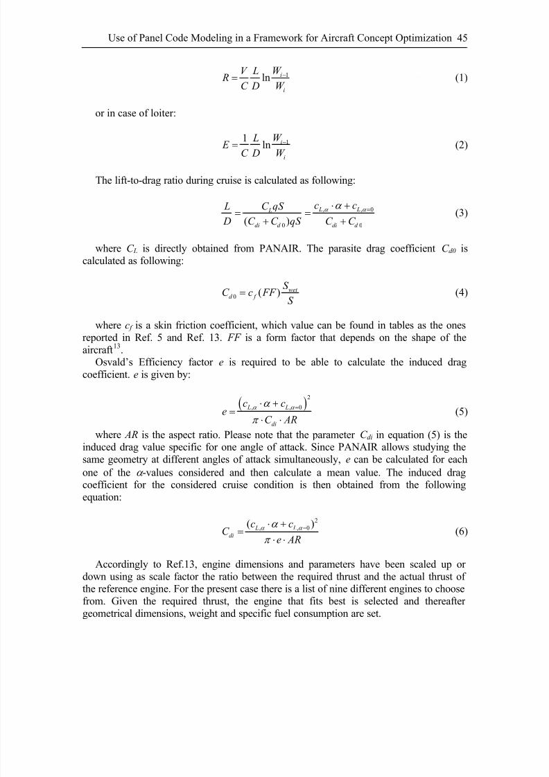
8/2/2019 K Amadori On Conceptual Aircraft Design
http://slidepdf.com/reader/full/k-amadori-on-conceptual-aircraft-design 59/101
Use of Panel Code Modeling in a Framework for Aircraft Concept Optimization 45
1ln i
i
W V L R
C D W
−= (1)
or in case of loiter:
11 ln i
i
W L E C D W
−= (2)
The lift-to-drag ratio during cruise is calculated as following:
, ,
0 0( ) L L L
di d di d
c c L C qS
D C C qS C C
α 0α α =⋅ += =
+ +(3)
where C L is directly obtained from PANAIR. The parasite drag coefficient C d0 iscalculated as following:
0 ( ) wet d f
S C c FF
S = (4)
where c f is a skin friction coefficient, which value can be found in tables as the onesreported in Ref. 5 and Ref. 13. FF is a form factor that depends on the shape of theaircraft13.
Osvald’s Efficiency factor e is required to be able to calculate the induced dragcoefficient. e is given by:
( )
2
, , L L
di
c ceC AR
α α α π
=⋅ +
= ⋅ ⋅0 (5)
where AR is the aspect ratio. Please note that the parameter C di in equation (5) is theinduced drag value specific for one angle of attack. Since PANAIR allows studying thesame geometry at different angles of attack simultaneously, e can be calculated for eachone of the α -values considered and then calculate a mean value. The induced dragcoefficient for the considered cruise condition is then obtained from the followingequation:
2, ,( L L
di
c cC
e AR
α α α
π
=⋅ +=
⋅ ⋅0 )
(6)
Accordingly to Ref.13, engine dimensions and parameters have been scaled up or down using as scale factor the ratio between the required thrust and the actual thrust of the reference engine. For the present case there is a list of nine different engines to choosefrom. Given the required thrust, the engine that fits best is selected and thereafter geometrical dimensions, weight and specific fuel consumption are set.

8/2/2019 K Amadori On Conceptual Aircraft Design
http://slidepdf.com/reader/full/k-amadori-on-conceptual-aircraft-design 60/101
Paper I46
An important constraint to the optimization is given by the limit stress requirements inthe structure. Since the structure has to be resistant enough to withstand all the flyingloads, this requirement avoids that the optimizer gives a solution where all thicknessesare at the minimum allowed value in order to reduce drag as much as possible. Since theCAD module that incorporates the finite element analysis was not used here, the structure
calculation is merged with the weight estimation of wing and fuselage. The equationsused for estimating the empty weights of wing and fuselage are obtained from statisticalanalysis of existing aircrafts13, so that the weight calculated comprises by itself the needfor enough structural strength.
W 0 can be considered being the sum of the required fuel weight (W f ) that is calculatedfrom the mission profile as a product of fractions of W 0
13, the aircraft’s empty weight(W e), the payload weight (W p), the engine weight (W eng ) and the control system weight(W CTRL), as described by the following equation:
0 e f p eng CT W W W W W W RL= + + + + (6)
The framework described in Section II will comprise a module for control systemdesign and optimization. So far it has not been included and therefore the weight of actuators, pipelines, reservoirs, tanks and other components has been included into theaircraft empty weight, while the computer hardware weight is the one labelled W CTRL, andit has been estimated by comparison with known flying aircrafts.
D. OptimizerThe data gathered from PANAIR are finally merged into an objective function
(ObjFun) that expresses quantitatively the goodness of one given concept. The objectivefunction takes into account both take-off weight of the aircraft and how close some of its predicted characteristics are to predefined wanted values, as in equation (7):
1 2
0
1 2
0,
mTC C fuel S
nom nom
W P P P P P BObjFun K K
W B
β β
α ⎛ ⎞+ + + + + ⎛ ⎞= +⎜ ⎟ ⎜ ⎟
⎝ ⎠⎝ ⎠(7)
The factors K 1, K 2, β 1 and β 2 are constants used to assign the wanted weight to the twoterms of the equation. W 0,nom and Bnom are the take-off weight and the span width of anominal configuration used as reference. P TC , P α , P Cm, P fuel , and P S are penalties that areused, together with constraints, to lead the optimizer away from unwanted configurations.The definition of the related penalty functions can be found in the following Section III-E. In the considered mission there are only straight-line cruises and there is no account
for manoeuvring performances. Thus the aim of the second term of the objective functionis to award configurations with better rolling rate that is, in first approximation, inversely proportional to the span width.
The optimization problem can be described as following:

8/2/2019 K Amadori On Conceptual Aircraft Design
http://slidepdf.com/reader/full/k-amadori-on-conceptual-aircraft-design 61/101
Use of Panel Code Modeling in a Framework for Aircraft Concept Optimization 47
min max
.
.
, .
min max
min max
min
. .
0
. . . . . .
req
req
eff eff all
m
cruise
ObjFun
s t
x x x
R R
E E
c
S M S M S M
α
σ σ
α α α
≤ ≤
≥
≥≤
<
< <
< <
(8)
Three different optimization algorithms have been used to solve the problem:Complex8-10, Fmincon and a Genetic Algorithm. Results are presented in Section V.
E. Penalty FunctionsSome of the problem constraints have been implemented as penalties added to the
objective function, so to lead the configuration of the aircraft towards the feasible regionsof the design space. The penalty value increases rapidly as soon as the given limit value is passed.1. Thickness-To-Chord Ratio Penalty (P TC )
The first penalty function is aimed at ensuring that the considered configuration allowsthe engine and the payload bay to be fit inside the aircraft. The actual thickness at thecentre line is calculated and compared to the height of the payload bay summed to theengine diameter. The penalty is then calculated as following:
0
eng PB R R D H t C TC eng PB R R
TC eng PB R R
P K e if D H t C
P if D H
+ − ⋅
⎧ = ⋅ + > ⋅⎪⎨= +⎪⎩ t C ≤ ⋅
(9)
where Deng is the engine diameter, H PB is the height of the payload bay.2. Angle Of Attack Penalty (P α )
In order to reduce drag and radar cross section, the angle of attack in cruise conditionis preferred to be positive and not larger than few degrees. Therefore a penalty functionhas been implemented as following:
( )
( )
1 max
2 min
1, max
2, min
min max
0
0
cruise
cruise
cruise
cruise
cruise
P K e if
P K e if
P if
β α α
α α
β α α
α α
α
α α
α α
α α α
−
−
⎧ = >
⎪⎪ =⎨⎪ = <⎪⎩
< =
<
(10)
where K 1,α , K 2,α , β 1 and β 2 are constants used to give the wanted weight to the terms inthe equations.
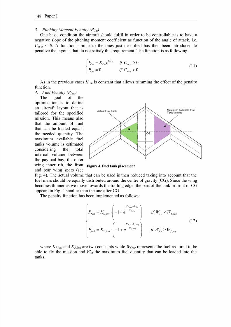
8/2/2019 K Amadori On Conceptual Aircraft Design
http://slidepdf.com/reader/full/k-amadori-on-conceptual-aircraft-design 62/101
Paper I48
3. Pitching Moment Penalty (P Cm )One basic condition the aircraft should fulfil in order to be controllable is to have a
negative slope of the pitching moment coefficient as function of the angle of attack, i.e.C m,α < 0. A function similar to the ones just described has then been introduced to penalize the layouts that do not satisfy this requirement. The function is as following:
,
,
,
0
0 0
mC
Cm Cm m
Cm m
P K e if C
P if C
α
α
α
⎧ = ≥⎪⎨
= <⎪⎩(11)
As in the previous cases K Cm is constant that allows trimming the effect of the penaltyfunction.4. Fuel Penalty (P fuel )
The goal of theoptimization is to definean aircraft layout that is
tailored for the specifiedmission. This means alsothat the amount of fuelthat can be loaded equalsthe needed quantity. Themaximum available fueltanks volume is estimatedconsidering the totalinternal volume betweenthe payload bay, the outer wing inner rib, the front
and rear wing spars (seeFig. 4). The actual volume that can be used is then reduced taking into account that thefuel mass should be equally distributed around the centre of gravity (CG). Since the wing becomes thinner as we move towards the trailing edge, the part of the tank in front of CGappears in Fig. 4 smaller than the one after CG.
Figure 4. Fuel tank placement
The penalty function has been implemented as follows:
, ,
,
, ,
,
1, , ,
2, , ,
1
1
f req f t
f req
f t f req
f req
W W
W
fuel fuel f t f req
W W
W
fuel fuel f t f req
P K e if W W
P K e if W W
−
−
⎧ ⎛ ⎞⎪ ⎜ ⎟= ⋅ − + <
⎜ ⎟⎪⎪ ⎝ ⎠⎨
⎛ ⎞⎪
⎜ ⎟= ⋅ − + ≥⎪ ⎜ ⎟⎪ ⎝ ⎠⎩
(12)
where K 1,fuel and K 2,fuel are two constants while W f,req represents the fuel required to beable to fly the mission and W f,t the maximum fuel quantity that can be loaded into thetanks.
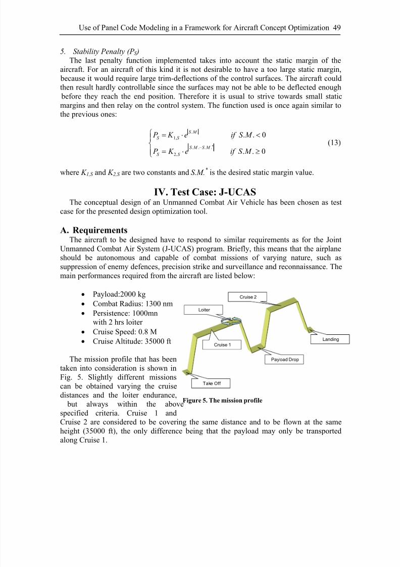
8/2/2019 K Amadori On Conceptual Aircraft Design
http://slidepdf.com/reader/full/k-amadori-on-conceptual-aircraft-design 63/101
Use of Panel Code Modeling in a Framework for Aircraft Concept Optimization 49
5. Stability Penalty (P S )The last penalty function implemented takes into account the static margin of the
aircraft. For an aircraft of this kind it is not desirable to have a too large static margin, because it would require large trim-deflections of the control surfaces. The aircraft couldthen result hardly controllable since the surfaces may not be able to be deflected enough
before they reach the end position. Therefore it is usual to strive towards small staticmargins and then relay on the control system. The function used is once again similar tothe previous ones:
. .1,
. . . .
2,
. . 0
. . 0
S M
S S
S M S M
S S
P K e if S M
P K e if S M ∗−
⎧ = ⋅ <⎪⎨
= ⋅ ≥⎪⎩
(13)
where K 1,S and K 2,S are two constants and S.M.* is the desired static margin value.
IV. Test Case: J-UCASThe conceptual design of an Unmanned Combat Air Vehicle has been chosen as test
case for the presented design optimization tool.
A. RequirementsThe aircraft to be designed have to respond to similar requirements as for the Joint
Unmanned Combat Air System (J-UCAS) program. Briefly, this means that the airplaneshould be autonomous and capable of combat missions of varying nature, such assuppression of enemy defences, precision strike and surveillance and reconnaissance. Themain performances required from the aircraft are listed below:
• Payload:2000 kg• Combat Radius: 1300 nm
• Persistence: 1000mnwith 2 hrs loiter
• Cruise Speed: 0.8 M• Cruise Altitude: 35000 ft
The mission profile that has beentaken into consideration is shown inFig. 5. Slightly different missionscan be obtained varying the cruise
distances and the loiter endurance, but always within the abovespecified criteria. Cruise 1 andCruise 2 are considered to be covering the same distance and to be flown at the sameheight (35000 ft), the only difference being that the payload may only be transportedalong Cruise 1.
Payload Drop
Take Off
Landing
Loiter
Cruise 1
Cruise 2
Figure 5. The mission profile
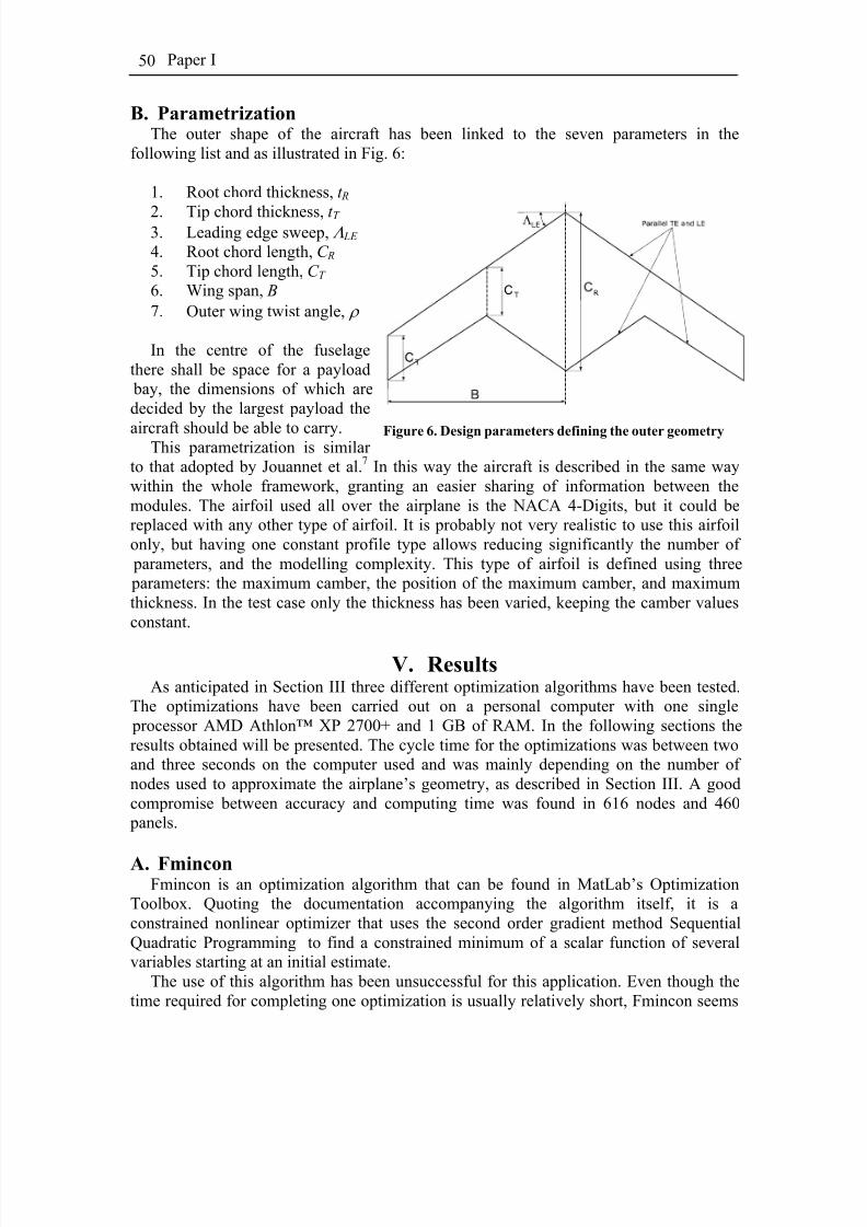
8/2/2019 K Amadori On Conceptual Aircraft Design
http://slidepdf.com/reader/full/k-amadori-on-conceptual-aircraft-design 64/101
Paper I50
B. ParametrizationThe outer shape of the aircraft has been linked to the seven parameters in the
following list and as illustrated in Fig. 6:
1. Root chord thickness, t R
2. Tip chord thickness, t T 3. Leading edge sweep, Λ LE 4. Root chord length, C R 5. Tip chord length, C T 6. Wing span, B 7. Outer wing twist angle, ρ
In the centre of the fuselagethere shall be space for a payload bay, the dimensions of which aredecided by the largest payload the
aircraft should be able to carry.This parametrization is similar to that adopted by Jouannet et al.7 In this way the aircraft is described in the same waywithin the whole framework, granting an easier sharing of information between themodules. The airfoil used all over the airplane is the NACA 4-Digits, but it could bereplaced with any other type of airfoil. It is probably not very realistic to use this airfoilonly, but having one constant profile type allows reducing significantly the number of parameters, and the modelling complexity. This type of airfoil is defined using three parameters: the maximum camber, the position of the maximum camber, and maximumthickness. In the test case only the thickness has been varied, keeping the camber valuesconstant.
Figure 6. Design parameters defining the outer geometry
V. ResultsAs anticipated in Section III three different optimization algorithms have been tested.
The optimizations have been carried out on a personal computer with one single processor AMD Athlon™ XP 2700+ and 1 GB of RAM. In the following sections theresults obtained will be presented. The cycle time for the optimizations was between twoand three seconds on the computer used and was mainly depending on the number of nodes used to approximate the airplane’s geometry, as described in Section III. A goodcompromise between accuracy and computing time was found in 616 nodes and 460 panels.
A. FminconFmincon is an optimization algorithm that can be found in MatLab’s Optimization
Toolbox. Quoting the documentation accompanying the algorithm itself, it is aconstrained nonlinear optimizer that uses the second order gradient method SequentialQuadratic Programming to find a constrained minimum of a scalar function of severalvariables starting at an initial estimate.
The use of this algorithm has been unsuccessful for this application. Even though thetime required for completing one optimization is usually relatively short, Fmincon seems
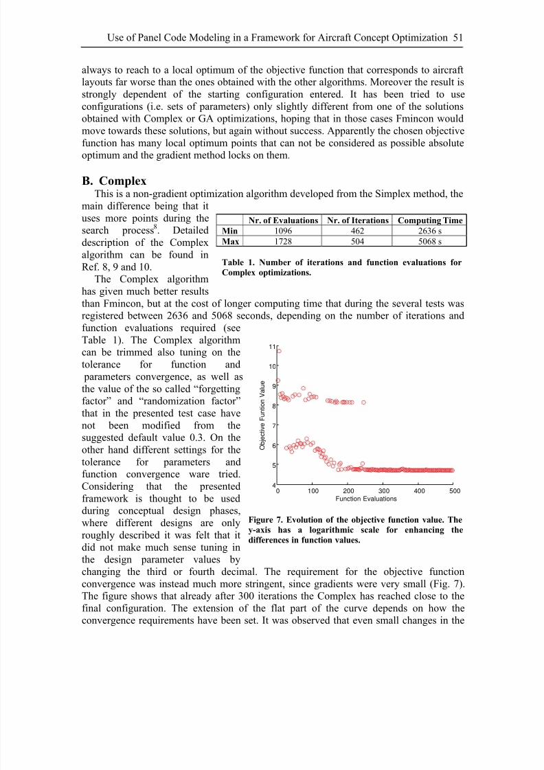
8/2/2019 K Amadori On Conceptual Aircraft Design
http://slidepdf.com/reader/full/k-amadori-on-conceptual-aircraft-design 65/101
Use of Panel Code Modeling in a Framework for Aircraft Concept Optimization 51
always to reach to a local optimum of the objective function that corresponds to aircraftlayouts far worse than the ones obtained with the other algorithms. Moreover the result isstrongly dependent of the starting configuration entered. It has been tried to useconfigurations (i.e. sets of parameters) only slightly different from one of the solutionsobtained with Complex or GA optimizations, hoping that in those cases Fmincon would
move towards these solutions, but again without success. Apparently the chosen objectivefunction has many local optimum points that can not be considered as possible absoluteoptimum and the gradient method locks on them.
B. ComplexThis is a non-gradient optimization algorithm developed from the Simplex method, the
main difference being that ituses more points during thesearch process8. Detaileddescription of the Complexalgorithm can be found in
Ref. 8, 9 and 10.The Complex algorithmhas given much better resultsthan Fmincon, but at the cost of longer computing time that during the several tests wasregistered between 2636 and 5068 seconds, depending on the number of iterations andfunction evaluations required (seeTable 1). The Complex algorithmcan be trimmed also tuning on thetolerance for function and parameters convergence, as well asthe value of the so called “forgetting
factor” and “randomization factor”that in the presented test case havenot been modified from thesuggested default value 0.3. On theother hand different settings for thetolerance for parameters andfunction convergence ware tried.Considering that the presentedframework is thought to be usedduring conceptual design phases,where different designs are only
roughly described it was felt that itdid not make much sense tuning inthe design parameter values bychanging the third or fourth decimal. The requirement for the objective functionconvergence was instead much more stringent, since gradients were very small (Fig. 7).The figure shows that already after 300 iterations the Complex has reached close to thefinal configuration. The extension of the flat part of the curve depends on how theconvergence requirements have been set. It was observed that even small changes in the
Nr. of Evaluations Nr. of Iterations Computing Time
Min 1096 462 2636 sMax 1728 504 5068 s
Table 1. Number of iterations and function evaluations for
Complex optimizations.
0 100 200 300 400 5004
5
6
7
8
9
10
11
Function Evaluations
O b j e c t i v e F u n t i o
n V a l u e
Figure 7. Evolution of the objective function value. The
y-axis has a logarithmic scale for enhancing the
differences in function values.
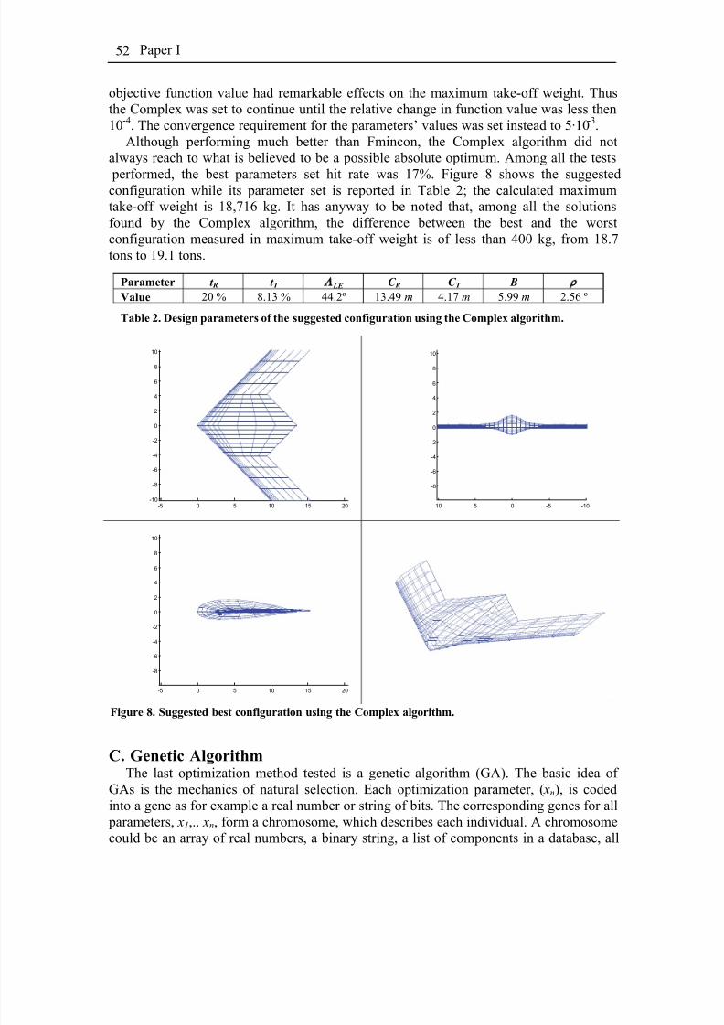
8/2/2019 K Amadori On Conceptual Aircraft Design
http://slidepdf.com/reader/full/k-amadori-on-conceptual-aircraft-design 66/101
Paper I52
objective function value had remarkable effects on the maximum take-off weight. Thusthe Complex was set to continue until the relative change in function value was less then10-4. The convergence requirement for the parameters’ values was set instead to 5·10-3.
Although performing much better than Fmincon, the Complex algorithm did notalways reach to what is believed to be a possible absolute optimum. Among all the tests
performed, the best parameters set hit rate was 17%. Figure 8 shows the suggestedconfiguration while its parameter set is reported in Table 2; the calculated maximumtake-off weight is 18,716 kg. It has anyway to be noted that, among all the solutionsfound by the Complex algorithm, the difference between the best and the worstconfiguration measured in maximum take-off weight is of less than 400 kg, from 18.7tons to 19.1 tons.
Parameter t R t T Λ LE C R C T B ρ
Value 20 % 8.13 % 44.2º 13.49 m 4.17 m 5.99 m 2.56 º
Table 2. Design parameters of the suggested configuration using the Complex algorithm.
C. Genetic AlgorithmThe last optimization method tested is a genetic algorithm (GA). The basic idea of
GAs is the mechanics of natural selection. Each optimization parameter, ( xn), is codedinto a gene as for example a real number or string of bits. The corresponding genes for all parameters, x1,.. xn, form a chromosome, which describes each individual. A chromosomecould be an array of real numbers, a binary string, a list of components in a database, all
-5 0 5 10 15 20-10
-8
-6
-4
-2
0
2
4
6
8
10
-10-50510
-8
-6
-4
-2
0
2
4
6
8
10
-5 0 5 10 15 20
-8
-6
-4
-2
0
2
4
6
8
10
Figure 8. Suggested best configuration using the Complex algorithm.

8/2/2019 K Amadori On Conceptual Aircraft Design
http://slidepdf.com/reader/full/k-amadori-on-conceptual-aircraft-design 67/101
Use of Panel Code Modeling in a Framework for Aircraft Concept Optimization 53
depending on the specific problem. Each individual represents a possible solution, and aset of individuals form a population. In a population, the fittest are selected for mating.Mating is performed by combining genes from different parents to produce a child, calleda crossover. There is also a possibility that a mutation might occur which change thevalue of a gene randomly. Finally the children are inserted into the population to form a
new generation. The procedure starts over again, thus representing an artificial Darwinianenvironment. The optimization continues until the population has converged or themaximum number of generations has been reached. The implemented GA uses realencoding, roulette wheel selection, extended intermediate recombination, mutationaccording to the breeder GA, linear fitness scaling and an elitist replacement strategywhere the GGap percentage of the weakest individuals is replaced in each generation. The present GA used a population size of 40 individuals and was run for 100 generations witha crossover probability of 0.6 and a generation gap of 0.8.
Compared to the other algorithms it registered the longest computing time due to thelarger number of iterations and objective function evaluations required. The totalcomputing time was around 2.5 hours that is in line with data from Table 1. On the other
hand, using this genetic algorithm the hit rate rose to 75%. One criterion for comparingthe Complex and GA could be to consider following performance index definition9:
2,
(1 )opt
obj opt
m
Log P f
k
−= − (14)
where P opt is the probability of finding the optmum and k m is the number of iterationsrequired. According to this definition the performance index of the GA is only three times better than the Complex algorithm. The difference is in fact not as big as it might seem atfirst.
Figure 9 shows the best configuration obtained and Table 3 its design parameters. The
calculated maximum take-off weight for this aircraft is 18,656 kg, which is almostexactly the same value obtained with the Complex algorithm. It should be remarked thatall the configurations obtained with the genetic algorithm that seems to be absoluteoptima do not have the same calculated take-off weight: among all the tests carried outthere is a variation of 0.95%. The objective function value diagram in Fig. 10 shows thatthere can be a big difference in the way the algorithm finds its way to the optimum. In both the cases the suggested configuration is exactly the same.
Parameter t R t T Λ LE C R C T B ρ
Value 20 % 8.15 % 44.11º 13.50 m 4.21 m 6.00 m 2.20 º
Table 3. Design parameters of the suggested best configuration using the genetic algorithm.
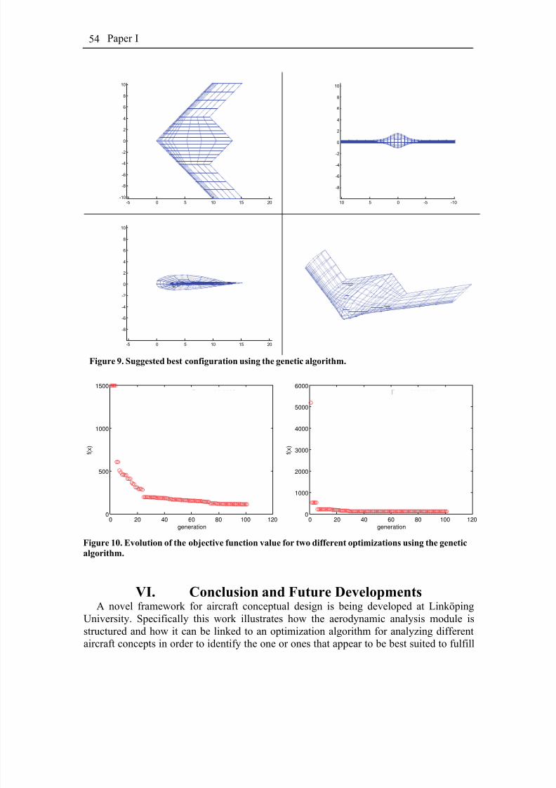
8/2/2019 K Amadori On Conceptual Aircraft Design
http://slidepdf.com/reader/full/k-amadori-on-conceptual-aircraft-design 68/101
Paper I54
-5 0 5 10 15 20-10
-8
-6
-4
-2
0
2
4
6
8
10
-10-50510
-8
-6
-4
-2
0
2
4
6
8
10
-5 0 5 10 15 20
-8
-6
-4
-2
0
2
4
6
8
10
Figure 9. Suggested best configuration using the genetic algorithm.
0 20 40 60 80 100 1200
500
1000
1500
generation
f ( x )
Best = 110.0285
0 20 40 60 80 100 1200
1000
2000
3000
4000
5000
6000
generation
f ( x )
Best = 109.4649
Figure 10. Evolution of the objective function value for two different optimizations using the genetic
algorithm.
VI. Conclusion and Future DevelopmentsA novel framework for aircraft conceptual design is being developed at Linköping
University. Specifically this work illustrates how the aerodynamic analysis module isstructured and how it can be linked to an optimization algorithm for analyzing differentaircraft concepts in order to identify the one or ones that appear to be best suited to fulfill
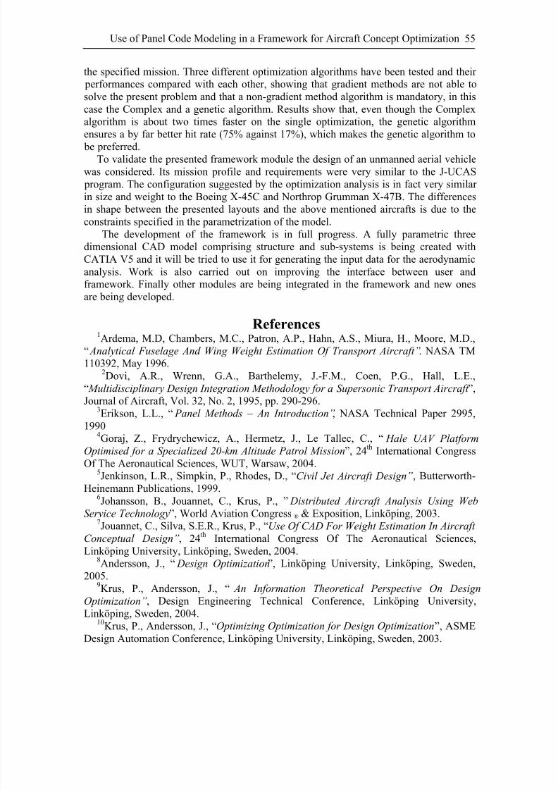
8/2/2019 K Amadori On Conceptual Aircraft Design
http://slidepdf.com/reader/full/k-amadori-on-conceptual-aircraft-design 69/101
Use of Panel Code Modeling in a Framework for Aircraft Concept Optimization 55
the specified mission. Three different optimization algorithms have been tested and their performances compared with each other, showing that gradient methods are not able tosolve the present problem and that a non-gradient method algorithm is mandatory, in thiscase the Complex and a genetic algorithm. Results show that, even though the Complexalgorithm is about two times faster on the single optimization, the genetic algorithm
ensures a by far better hit rate (75% against 17%), which makes the genetic algorithm to be preferred.To validate the presented framework module the design of an unmanned aerial vehicle
was considered. Its mission profile and requirements were very similar to the J-UCAS program. The configuration suggested by the optimization analysis is in fact very similar in size and weight to the Boeing X-45C and Northrop Grumman X-47B. The differencesin shape between the presented layouts and the above mentioned aircrafts is due to theconstraints specified in the parametrization of the model.
The development of the framework is in full progress. A fully parametric threedimensional CAD model comprising structure and sub-systems is being created withCATIA V5 and it will be tried to use it for generating the input data for the aerodynamic
analysis. Work is also carried out on improving the interface between user andframework. Finally other modules are being integrated in the framework and new onesare being developed.
References1Ardema, M.D, Chambers, M.C., Patron, A.P., Hahn, A.S., Miura, H., Moore, M.D.,
“ Analytical Fuselage And Wing Weight Estimation Of Transport Aircraft”. NASA TM110392, May 1996.
2Dovi, A.R., Wrenn, G.A., Barthelemy, J.-F.M., Coen, P.G., Hall, L.E.,“ Multidisciplinary Design Integration Methodology for a Supersonic Transport Aircraft ”,Journal of Aircraft, Vol. 32, No. 2, 1995, pp. 290-296.
3
Erikson, L.L., “ Panel Methods – An Introduction”, NASA Technical Paper 2995,19904Goraj, Z., Frydrychewicz, A., Hermetz, J., Le Tallec, C., “ Hale UAV Platform
Optimised for a Specialized 20-km Altitude Patrol Mission”, 24th International CongressOf The Aeronautical Sciences, WUT, Warsaw, 2004.
5Jenkinson, L.R., Simpkin, P., Rhodes, D., “Civil Jet Aircraft Design”, Butterworth-Heinemann Publications, 1999.
6Johansson, B., Jouannet, C., Krus, P., ” Distributed Aircraft Analysis Using Web
Service Technology”, World Aviation Congress ® & Exposition, Linköping, 2003.7Jouannet, C., Silva, S.E.R., Krus, P., “Use Of CAD For Weight Estimation In Aircraft
Conceptual Design”, 24th International Congress Of The Aeronautical Sciences,
Linköping University, Linköping, Sweden, 2004.8Andersson, J., “ Design Optimization”, Linköping University, Linköping, Sweden,2005.
9Krus, P., Andersson, J., “ An Information Theoretical Perspective On Design
Optimization”, Design Engineering Technical Conference, Linköping University,Linköping, Sweden, 2004.
10Krus, P., Andersson, J., “Optimizing Optimization for Design Optimization”, ASMEDesign Automation Conference, Linköping University, Linköping, Sweden, 2003.

8/2/2019 K Amadori On Conceptual Aircraft Design
http://slidepdf.com/reader/full/k-amadori-on-conceptual-aircraft-design 70/101
Paper I56
11Lovell, D.A., Crawford, C.A., Restrick, K.E., “ Recent Advances In Air-Vehicle
Design Synthesis And Optimisation”, 24th International Congress Of The AeronauticalSciences, Farnborough, UK, 2004.
12Morris, A., Arendsen, P., LaRocca, G., Laban, M., Voss, R., Hönlinger, H., “ MOB
– A European Project on Multidisciplinary Design Optimization”, 24th International
Congress Of The Aeronautical Sciences, Cranfield University, UK, 200413Raymer, D.P., “ Aircraft Design: A Conceptual Approach”. Second Edition, AIAAEducational Series, 1992.
14Röhl, P.J., Mavris, D.M., Schrage, D.P., “Combined Aerodynamic and Structural
Optimization of a High-Speed Civil Transport Wing ”, Georgia Institute of Technology,Atlanta, GA, 1995.
15Sevant, N.E., Bloor, M.I.G., Wilson, M.J., “Cost Effective Multipoint Design of a Blended High-Speed Civil Transport”, Journal of Aircraft, Vol. 36, No. 4, 1999, pp. 642-650.
16Towne, M.C., Strande, S.M., Erikson, L.L., Kroo, J.M., Enomoto, F.Y., Carmichael,R.L., McPherson, K.F., “ PAN AIR Modelling Studies”, AIAA Applied Aerodynamics
Conference, NASA Ames Research Center, Moffet Field, California, 1983.

8/2/2019 K Amadori On Conceptual Aircraft Design
http://slidepdf.com/reader/full/k-amadori-on-conceptual-aircraft-design 71/101
Paper II
A Framework for Aerodynamic and Structural
Optimization in Conceptual Design
Kristian Amadori(1), Christopher Jouannet(2), Petter Krus(1)
(1) Department of Management and Engineering – Division of Machine Design(2) Department of Management and Engineering – Division of Fluid and Mechanical
Engineering Systems
Abstract
Aircraft design is an inherently multidisciplinary activity that requires differentmodels and tools for various aspects of the design. At Linköping University a novel
design framework is being developed to support the initial conceptual design phase of anew aircraft. In this work main attention has been paid to wing design, with respect toaerodynamic efficiency and loads, and to structural analysis. By linking together variousmodules via a user-friendly interface based on a spreadsheet, the framework allowsmultidisciplinary analysis and optimizations to be carried out. This paper will present theframework, give an overview of its development status and give an indication on thefuture work.

8/2/2019 K Amadori On Conceptual Aircraft Design
http://slidepdf.com/reader/full/k-amadori-on-conceptual-aircraft-design 72/101
Paper II58
This paper has been published as:Amadori, K., Jouannet, C. and Krus, P., ” A Framework for Aerodynamic and Structural Optimization in Conceptual Design”, June 2007, 25th AIAA Applied AerodynamicsConference, Miami, FL, USA
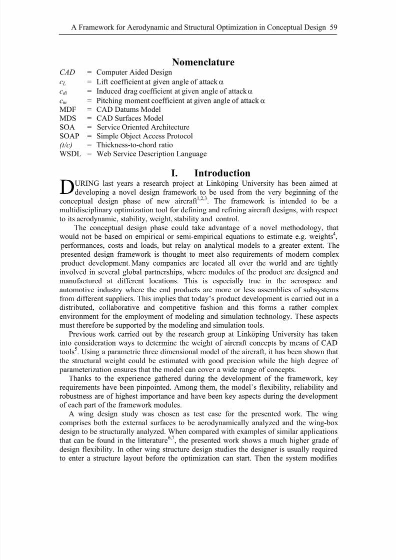
8/2/2019 K Amadori On Conceptual Aircraft Design
http://slidepdf.com/reader/full/k-amadori-on-conceptual-aircraft-design 73/101
A Framework for Aerodynamic and Structural Optimization in Conceptual Design 59
NomenclatureCAD = Computer Aided Designc L = Lift coefficient at given angle of attack α cdi = Induced drag coefficient at given angle of attack α cm = Pitching moment coefficient at given angle of attack α MDF = CAD Datums ModelMDS = CAD Surfaces ModelSOA = Service Oriented ArchitectureSOAP = Simple Object Access Protocol(t/c) = Thickness-to-chord ratioWSDL = Web Service Description Language
I. IntroductionURING last years a research project at Linköping University has been aimed at
developing a novel design framework to be used from the very beginning of theconceptual design phase of new aircraft1,2,3. The framework is intended to be amultidisciplinary optimization tool for defining and refining aircraft designs, with respectto its aerodynamic, stability, weight, stability and control.D
The conceptual design phase could take advantage of a novel methodology, thatwould not be based on empirical or semi-empirical equations to estimate e.g. weights4, performances, costs and loads, but relay on analytical models to a greater extent. The presented design framework is thought to meet also requirements of modern complex product development. Many companies are located all over the world and are tightlyinvolved in several global partnerships, where modules of the product are designed andmanufactured at different locations. This is especially true in the aerospace andautomotive industry where the end products are more or less assemblies of subsystemsfrom different suppliers. This implies that today’s product development is carried out in adistributed, collaborative and competitive fashion and this forms a rather complexenvironment for the employment of modeling and simulation technology. These aspectsmust therefore be supported by the modeling and simulation tools.
Previous work carried out by the research group at Linköping University has takeninto consideration ways to determine the weight of aircraft concepts by means of CADtools5. Using a parametric three dimensional model of the aircraft, it has been shown thatthe structural weight could be estimated with good precision while the high degree of parameterization ensures that the model can cover a wide range of concepts.
Thanks to the experience gathered during the development of the framework, keyrequirements have been pinpointed. Among them, the model’s flexibility, reliability androbustness are of highest importance and have been key aspects during the developmentof each part of the framework modules.
A wing design study was chosen as test case for the presented work. The wingcomprises both the external surfaces to be aerodynamically analyzed and the wing-boxdesign to be structurally analyzed. When compared with examples of similar applicationsthat can be found in the litterature6,7, the presented work shows a much higher grade of design flexibility. In other wing structure design studies the designer is usually requiredto enter a structure layout before the optimization can start. Then the system modifies
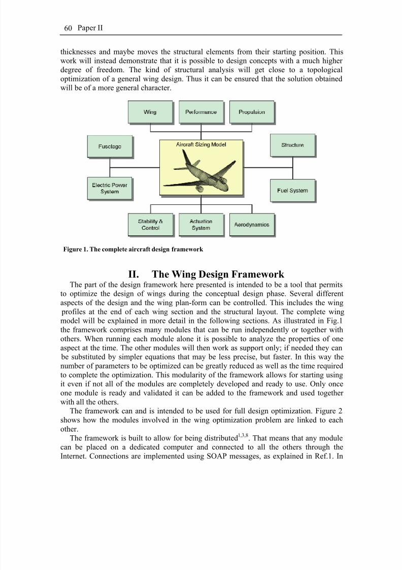
8/2/2019 K Amadori On Conceptual Aircraft Design
http://slidepdf.com/reader/full/k-amadori-on-conceptual-aircraft-design 74/101
Paper II60
thicknesses and maybe moves the structural elements from their starting position. Thiswork will instead demonstrate that it is possible to design concepts with a much higher degree of freedom. The kind of structural analysis will get close to a topologicaloptimization of a general wing design. Thus it can be ensured that the solution obtainedwill be of a more general character.
Figure 1. The complete aircraft design framework
II. The Wing Design Framework The part of the design framework here presented is intended to be a tool that permits
to optimize the design of wings during the conceptual design phase. Several differentaspects of the design and the wing plan-form can be controlled. This includes the wing profiles at the end of each wing section and the structural layout. The complete wingmodel will be explained in more detail in the following sections. As illustrated in Fig.1the framework comprises many modules that can be run independently or together withothers. When running each module alone it is possible to analyze the properties of oneaspect at the time. The other modules will then work as support only; if needed they can be substituted by simpler equations that may be less precise, but faster. In this way thenumber of parameters to be optimized can be greatly reduced as well as the time requiredto complete the optimization. This modularity of the framework allows for starting usingit even if not all of the modules are completely developed and ready to use. Only onceone module is ready and validated it can be added to the framework and used together
with all the others.The framework can and is intended to be used for full design optimization. Figure 2
shows how the modules involved in the wing optimization problem are linked to eachother.
The framework is built to allow for being distributed1,3,8. That means that any modulecan be placed on a dedicated computer and connected to all the others through theInternet. Connections are implemented using SOAP messages, as explained in Ref.1. In
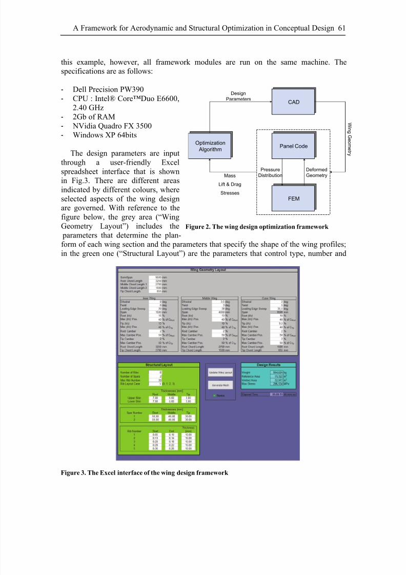
8/2/2019 K Amadori On Conceptual Aircraft Design
http://slidepdf.com/reader/full/k-amadori-on-conceptual-aircraft-design 75/101
A Framework for Aerodynamic and Structural Optimization in Conceptual Design 61
this example, however, all framework modules are run on the same machine. Thespecifications are as follows:
- Dell Precision PW390
- CPU : Intel® Core™Duo E6600,2.40 GHz- 2Gb of RAM- NVidia Quadro FX 3500- Windows XP 64bits
The design parameters are inputthrough a user-friendly Excelspreadsheet interface that is shownin Fig.3. There are different areasindicated by different colours, where
selected aspects of the wing designare governed. With reference to thefigure below, the grey area (“WingGeometry Layout”) includes the parameters that determine the plan-form of each wing section and the parameters that specify the shape of the wing profiles;in the green one (“Structural Layout”) are the parameters that control type, number and
CAD
Panel Code
Wi n g G e om e t r y
FEM
Pressure
Distribution
Deformed
Geometry
Optimization
Algorithm
Mass
Lift & Drag
Stresses
Design
Parameters
Figure 2. The wing design optimization framework
Figure 3. The Excel interface of the wing design framework

8/2/2019 K Amadori On Conceptual Aircraft Design
http://slidepdf.com/reader/full/k-amadori-on-conceptual-aircraft-design 76/101
Paper II62
placement of the structural element; finally in the light blue area (“Design Results”) theresults from the different modules are displayed.
The framework can be used both for automatic optimization of a particular design aswell as for exploring different design alternatives interactively. In the first case thespreadsheet is coupled with an optimization algorithm that acts on a set of input
parameters or on all of them. Otherwise the designer is asked to enter by hand the parameter values and to start the analysis.
III. The Parametric CAD ModelThe most important characteristic of the CAD model is to be highly flexible in order to
be able to represent a variety of designs as large as possible. Secondly the model must berobust and reliable, since there will not be a specialist entering new parameters andsupervising the update process. Itis fundamental that the model doesnot produce mathematical errorswithin its whole allowed design
range.
A. The Model StructureIn order to guarantee a high
degree of flexibility androbustness, the CAD model must be built in a proper way. Figure 4shows the relational links betweenthe different elements of themodel. The input parametersdescribed above govern directly
the “Datums Model” (MDF) andthe “Surfaces Model” (MDS). TheMDF-model is a wireframe modelwhere all reference planes andlines, needed to define the wingand its structure, are defined. It isimportant to notice that all thestructure components in the CADmodel depend on both the MDF-model and MDS-model, thatdepend instead only on the top
level input parameters. The MDSsurfaces model contains all theexternal surfaces.
Figure 4. Relational links between the different elements in
the CAD model
The structure is obtained byinstantiating a general structuralelement that is designed to adaptitself, given the following parameters that are specified in the Figure 5. The general structure element model
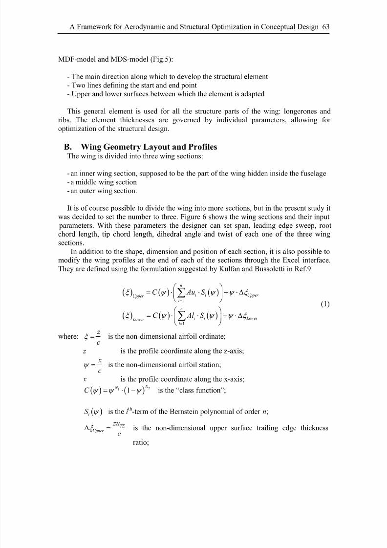
8/2/2019 K Amadori On Conceptual Aircraft Design
http://slidepdf.com/reader/full/k-amadori-on-conceptual-aircraft-design 77/101
A Framework for Aerodynamic and Structural Optimization in Conceptual Design 63
MDF-model and MDS-model (Fig.5):
- The main direction along which to develop the structural element- Two lines defining the start and end point
- Upper and lower surfaces between which the element is adapted
This general element is used for all the structure parts of the wing: longerones andribs. The element thicknesses are governed by individual parameters, allowing for optimization of the structural design.
B. Wing Geometry Layout and ProfilesThe wing is divided into three wing sections:
- an inner wing section, supposed to be the part of the wing hidden inside the fuselage- a middle wing section
- an outer wing section.
It is of course possible to divide the wing into more sections, but in the present study itwas decided to set the number to three. Figure 6 shows the wing sections and their input parameters. With these parameters the designer can set span, leading edge sweep, rootchord length, tip chord length, dihedral angle and twist of each one of the three wingsections.
In addition to the shape, dimension and position of each section, it is also possible tomodify the wing profiles at the end of each of the sections through the Excel interface.They are defined using the formulation suggested by Kulfan and Bussoletti in Ref.9:
( ) ( ) ( )
( ) ( ) ( )
1
1
n
i i Upper Upper i
n
i i Lower Lower i
C Au S
C Al S
ξ ψ ψ ψ
ξ ψ ψ ψ ξ
=
=
⎛ ⎞= ⋅ ⋅ + ⋅ Δ⎜ ⎟⎝ ⎠
⎛ ⎞= ⋅ ⋅ + ⋅ Δ⎜ ⎟
⎝ ⎠
∑
∑
ξ
(1)
where: z
cξ = is the non-dimensional airfoil ordinate;
z is the profile coordinate along the z-axis; x
cψ = is the non-dimensional airfoil station;
x is the profile coordinate along the x-axis;
is the “class function”;( ) ( ) 21 1 N N C ψ ψ ψ = ⋅ −
( )iS ψ is the ith-term of the Bernstein polynomial of order n;
TE Upper
zu
cξ Δ = is the non-dimensional upper surface trailing edge thickness
ratio;
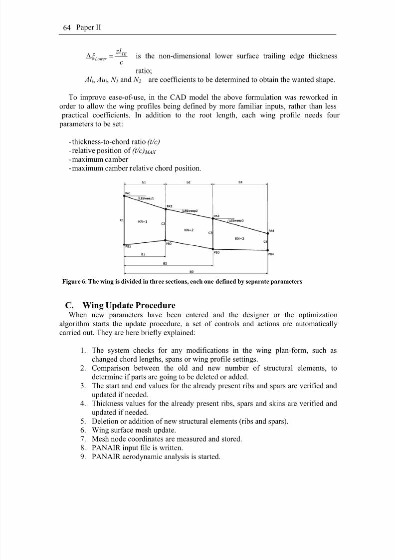
8/2/2019 K Amadori On Conceptual Aircraft Design
http://slidepdf.com/reader/full/k-amadori-on-conceptual-aircraft-design 78/101
Paper II64
TE Lower
zl
cξ Δ = is the non-dimensional lower surface trailing edge thickness
ratio; Al i, Aui, N 1 and N 2 are coefficients to be determined to obtain the wanted shape.
To improve ease-of-use, in the CAD model the above formulation was reworked inorder to allow the wing profiles being defined by more familiar inputs, rather than less practical coefficients. In addition to the root length, each wing profile needs four parameters to be set:
- thickness-to-chord ratio (t/c) - relative position of (t/c) MAX - maximum camber - maximum camber relative chord position.
Figure 6. The wing is divided in three sections, each one defined by separate parameters
C. Wing Update ProcedureWhen new parameters have been entered and the designer or the optimization
algorithm starts the update procedure, a set of controls and actions are automaticallycarried out. They are here briefly explained:
1. The system checks for any modifications in the wing plan-form, such aschanged chord lengths, spans or wing profile settings.
2. Comparison between the old and new number of structural elements, todetermine if parts are going to be deleted or added.
3. The start and end values for the already present ribs and spars are verified and
updated if needed.4. Thickness values for the already present ribs, spars and skins are verified and
updated if needed.5. Deletion or addition of new structural elements (ribs and spars).6. Wing surface mesh update.7. Mesh node coordinates are measured and stored.8. PANAIR input file is written.9. PANAIR aerodynamic analysis is started.
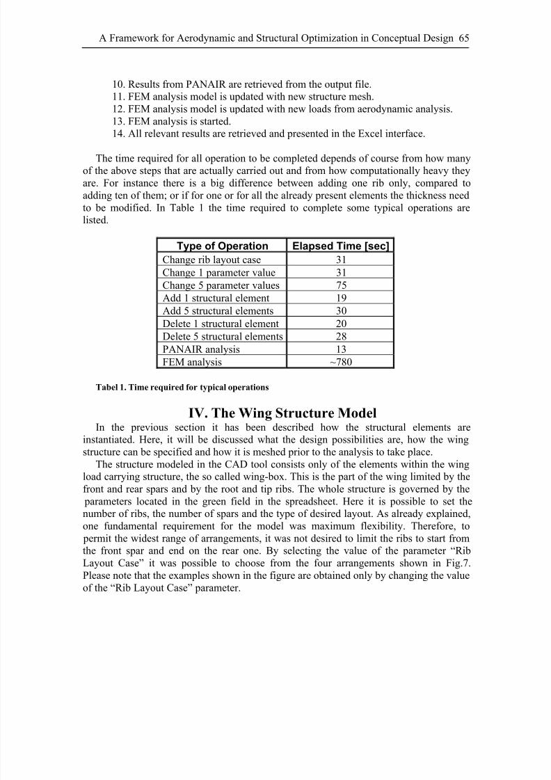
8/2/2019 K Amadori On Conceptual Aircraft Design
http://slidepdf.com/reader/full/k-amadori-on-conceptual-aircraft-design 79/101
A Framework for Aerodynamic and Structural Optimization in Conceptual Design 65
10. Results from PANAIR are retrieved from the output file.11. FEM analysis model is updated with new structure mesh.12. FEM analysis model is updated with new loads from aerodynamic analysis.13. FEM analysis is started.
14. All relevant results are retrieved and presented in the Excel interface.
The time required for all operation to be completed depends of course from how manyof the above steps that are actually carried out and from how computationally heavy theyare. For instance there is a big difference between adding one rib only, compared toadding ten of them; or if for one or for all the already present elements the thickness needto be modified. In Table 1 the time required to complete some typical operations arelisted.
Type of Operation Elapsed Time [sec]
Change rib layout case 31
Change 1 parameter value 31Change 5 parameter values 75Add 1 structural element 19Add 5 structural elements 30Delete 1 structural element 20Delete 5 structural elements 28PANAIR analysis 13FEM analysis ~780
Tabel 1. Time required for typical operations
IV. The Wing Structure ModelIn the previous section it has been described how the structural elements are
instantiated. Here, it will be discussed what the design possibilities are, how the wingstructure can be specified and how it is meshed prior to the analysis to take place.
The structure modeled in the CAD tool consists only of the elements within the wingload carrying structure, the so called wing-box. This is the part of the wing limited by thefront and rear spars and by the root and tip ribs. The whole structure is governed by the parameters located in the green field in the spreadsheet. Here it is possible to set thenumber of ribs, the number of spars and the type of desired layout. As already explained,one fundamental requirement for the model was maximum flexibility. Therefore, to permit the widest range of arrangements, it was not desired to limit the ribs to start fromthe front spar and end on the rear one. By selecting the value of the parameter “RibLayout Case” it was possible to choose from the four arrangements shown in Fig.7.Please note that the examples shown in the figure are obtained only by changing the valueof the “Rib Layout Case” parameter.
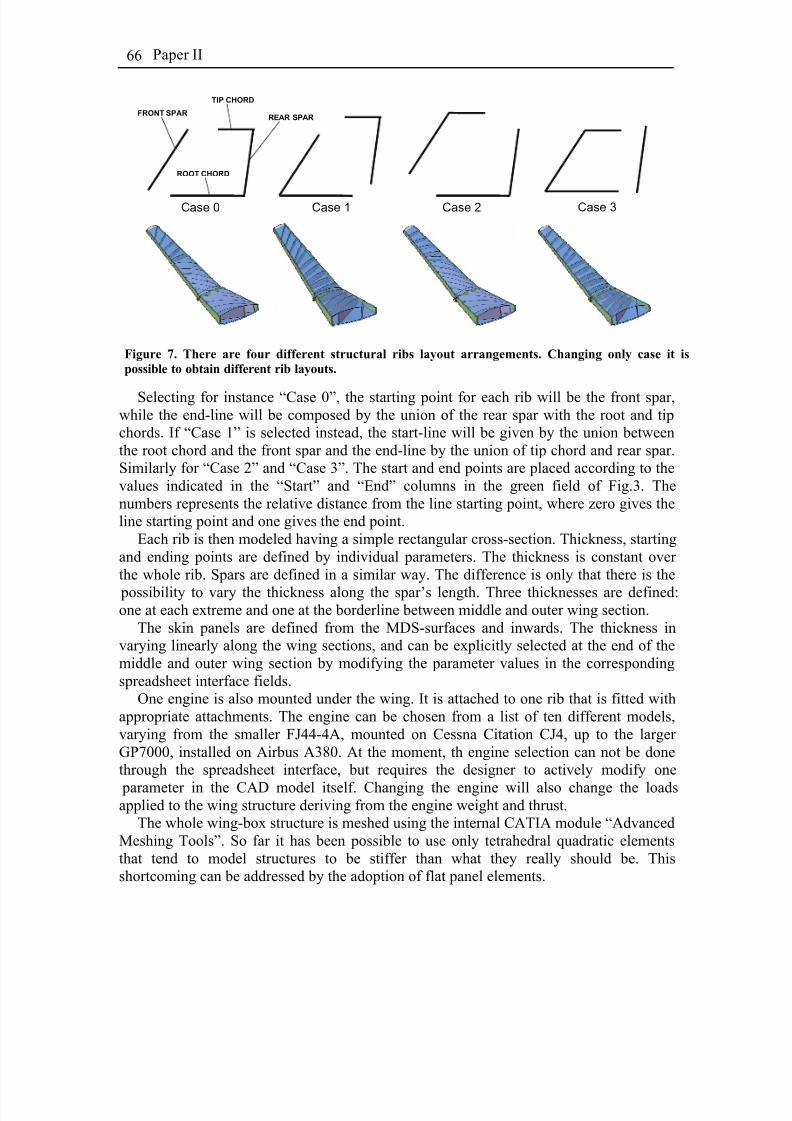
8/2/2019 K Amadori On Conceptual Aircraft Design
http://slidepdf.com/reader/full/k-amadori-on-conceptual-aircraft-design 80/101
Paper II66
Case 0 Case 1 Case 2 Case 3
FRONT SPARREAR SPAR
ROOT CHORD
TIP CHORD
Figure 7. There are four different structural ribs layout arrangements. Changing only case it is
possible to obtain different rib layouts.
Selecting for instance “Case 0”, the starting point for each rib will be the front spar,while the end-line will be composed by the union of the rear spar with the root and tipchords. If “Case 1” is selected instead, the start-line will be given by the union betweenthe root chord and the front spar and the end-line by the union of tip chord and rear spar.Similarly for “Case 2” and “Case 3”. The start and end points are placed according to thevalues indicated in the “Start” and “End” columns in the green field of Fig.3. Thenumbers represents the relative distance from the line starting point, where zero gives theline starting point and one gives the end point.
Each rib is then modeled having a simple rectangular cross-section. Thickness, startingand ending points are defined by individual parameters. The thickness is constant over the whole rib. Spars are defined in a similar way. The difference is only that there is the
possibility to vary the thickness along the spar’s length. Three thicknesses are defined:one at each extreme and one at the borderline between middle and outer wing section.
The skin panels are defined from the MDS-surfaces and inwards. The thickness invarying linearly along the wing sections, and can be explicitly selected at the end of themiddle and outer wing section by modifying the parameter values in the correspondingspreadsheet interface fields.
One engine is also mounted under the wing. It is attached to one rib that is fitted withappropriate attachments. The engine can be chosen from a list of ten different models,varying from the smaller FJ44-4A, mounted on Cessna Citation CJ4, up to the larger GP7000, installed on Airbus A380. At the moment, th engine selection can not be donethrough the spreadsheet interface, but requires the designer to actively modify one
parameter in the CAD model itself. Changing the engine will also change the loadsapplied to the wing structure deriving from the engine weight and thrust.
The whole wing-box structure is meshed using the internal CATIA module “AdvancedMeshing Tools”. So far it has been possible to use only tetrahedral quadratic elementsthat tend to model structures to be stiffer than what they really should be. Thisshortcoming can be addressed by the adoption of flat panel elements.
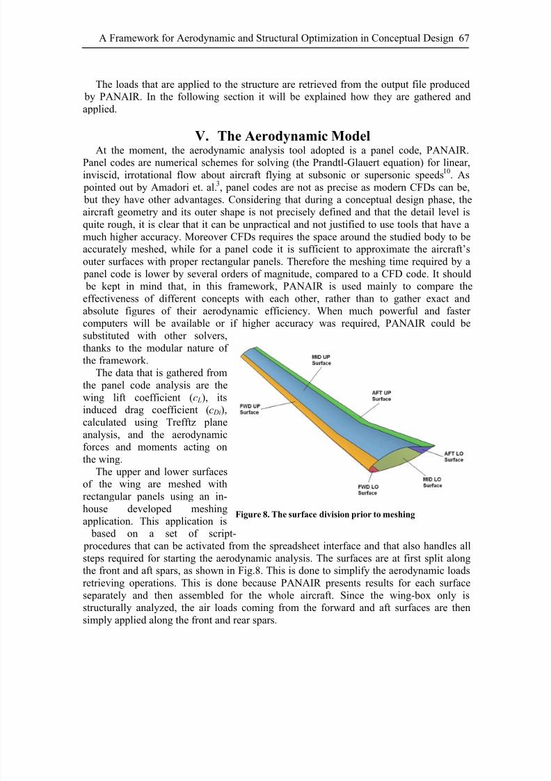
8/2/2019 K Amadori On Conceptual Aircraft Design
http://slidepdf.com/reader/full/k-amadori-on-conceptual-aircraft-design 81/101
A Framework for Aerodynamic and Structural Optimization in Conceptual Design 67
The loads that are applied to the structure are retrieved from the output file produced
by PANAIR. In the following section it will be explained how they are gathered andapplied.
V. The Aerodynamic ModelAt the moment, the aerodynamic analysis tool adopted is a panel code, PANAIR.
Panel codes are numerical schemes for solving (the Prandtl-Glauert equation) for linear,inviscid, irrotational flow about aircraft flying at subsonic or supersonic speeds10. As pointed out by Amadori et. al.3, panel codes are not as precise as modern CFDs can be, but they have other advantages. Considering that during a conceptual design phase, theaircraft geometry and its outer shape is not precisely defined and that the detail level isquite rough, it is clear that it can be unpractical and not justified to use tools that have amuch higher accuracy. Moreover CFDs requires the space around the studied body to beaccurately meshed, while for a panel code it is sufficient to approximate the aircraft’souter surfaces with proper rectangular panels. Therefore the meshing time required by a
panel code is lower by several orders of magnitude, compared to a CFD code. It should be kept in mind that, in this framework, PANAIR is used mainly to compare theeffectiveness of different concepts with each other, rather than to gather exact andabsolute figures of their aerodynamic efficiency. When much powerful and faster computers will be available or if higher accuracy was required, PANAIR could besubstituted with other solvers,thanks to the modular nature of the framework.
The data that is gathered fromthe panel code analysis are thewing lift coefficient (c L), its
induced drag coefficient (c Di),calculated using Trefftz planeanalysis, and the aerodynamicforces and moments acting onthe wing.
The upper and lower surfacesof the wing are meshed withrectangular panels using an in-house developed meshingapplication. This application is based on a set of script-
procedures that can be activated from the spreadsheet interface and that also handles allsteps required for starting the aerodynamic analysis. The surfaces are at first split alongthe front and aft spars, as shown in Fig.8. This is done to simplify the aerodynamic loadsretrieving operations. This is done because PANAIR presents results for each surfaceseparately and then assembled for the whole aircraft. Since the wing-box only isstructurally analyzed, the air loads coming from the forward and aft surfaces are thensimply applied along the front and rear spars.
Figure 8. The surface division prior to meshing

8/2/2019 K Amadori On Conceptual Aircraft Design
http://slidepdf.com/reader/full/k-amadori-on-conceptual-aircraft-design 82/101
Paper II68
Another advantage of using a tailor made meshing tool is that the coordinates for eachone of the meshing nodes can be stored directly in the appropriate order for PANAIR tocorrectly interpret them. Thus data handling is in this way simplified and speeded up.
Figure 9. Results from FEM analysis of the wing-box structure
VI. Optimization ProblemsThe presented models and framework can be used in different optimization scenarios,
employing different optimization tools. As for implementing optimization functionality,the most obvious is to use optimization software available in the user application. For example, the commercial software Crystal Ball with the optimization toolbox OptQuesthas been evaluated. OptQuest incorporates Metaheuristics to guide its search algorithm11.
It is capable of handling a wide range of problems and is executed as an integratedmodule of Excel. Another plug-in Design Analysis tools has been developed at LinköpingUniversity which includes sensitivity analysis, functional correlation, and support for both establishing and to carry out design optimization, Krus12. This can also be usedtogether with tools for statistical simulations for probabilistic design as in Mavris et al 13.Excel also has support for using web service technology and in this way models published as web services on other geographic locations can be connected and used in theanalysis and optimization. This has been done in other research projects carried out atLinköping University1-3,14. For optimization both the so-called Complex-RF method andgenetic algorithms have been implemented and deployed. The Complex algorithm wasoriginally presented by Box15, and is a non-gradient method which is appropriate for
problems where the objective function is defined by results from various calculations or simulations and the derivative of the objective function cannot be defined. The algorithmwas improved by Krus et. al.16 to increase the probability of reaching a global optimumand has been used very successfully over a wide range of problems and is characterized by simplicity and robustness.
By choosing the appropriate set of optimization variables among all the parametersthat can be governed through the Excel interface, a variety of engineering design problems could be solved. For instance one typical application could be to minimize the
8/2/2019 K Amadori On Conceptual Aircraft Design
http://slidepdf.com/reader/full/k-amadori-on-conceptual-aircraft-design 83/101
A Framework for Aerodynamic and Structural Optimization in Conceptual Design 69
wing weight and or drag, granting a given minimum lift force. The problem could beapproached with a fixed number of spars and ribs or with a variable number of them. Inthe second case of course the solution would be more general, but at the cost of longer computing time. Also which geometry layout parameters to include in the optimization
problem can be freely selected.
VII. Conclusions and Future Work In this paper a framework for wing design and optimization has been presented. It is
one part of a complete aircraft design framework that is being developed at LinköpingUniversity. The whole framework is intended to cover all the diverse parts and systemsthat an aircraft can be divided into: fuselage, wing, propulsion systems, landing gears,subsystems, structures, and control system.
The framework itself is innovative in several ways. First of all, the design tools are based on real models rather than historical data. Secondly, the modeling approach is anintegration of several distributed domain specific models which increases the possibilities
to gain more reliable design information early in the design process without revealing proprietary parts of the models. This is a very important aspect in real world design projects where several distributed participants must efficiently cooperate while protectingrestricted sensitive data.
The presented wing model is also innovative. It has been developed having itsflexibility as a fundamental requirement. Not only does it permit to modify and optimizea given wing design and one specified load carrying structure, but it also allows toradically change the configuration and layout of the structure design. Not only the sizeand relative position of structure elements can be changed, but also their number. If onerib is not required it will be removed. This means that a more general design can be usedfor the optimization, while minimizing the designer’s work load, since he/she will not be
asked to enter a qualified structural proposal prior to starting the optimization. Thus theresulting structural layout will not depend on how the wing-box is defined at the beginning of the optimization. In this sense the proposed framework will work similarlyto a topology optimization tool.
In order to verify the robustness and flexibility of the model a detailed analysis of themodel has been carried out. Now tests with optimization problems of increasingcomplexity will follow. The tests will be used to verify both how precise results can beobtained and to evaluate the optimization performance. Even though if compared tosimpler applications often used in conceptual design phases, the presented tool willclearly require longer computing time, the results obtained will be more detailed andreliable. The detail level of the obtained answers will also be far more exhaustive than
with classic tools. Moreover, since all elements are from the start modeled with CATIA,most of the models can be directly reused in further design steps. All together this leadsto reduced overall cost and time for a project.
At the moment investigations are also done to verify the possibility to employ other aerodynamic codes, such as ZOONAIR, ALIS or CFD codes like Edge (FFA) that willoffer increased accuracy and flexibility. Thanks to the modular structure of theframework, substituting one module is not compromising the functionality of the rest of them, which ensures to be able to always use the most profitable tools available.
8/2/2019 K Amadori On Conceptual Aircraft Design
http://slidepdf.com/reader/full/k-amadori-on-conceptual-aircraft-design 84/101
Paper II70
References1Johansson, B., Jouannet, C., Krus, P., ” Distributed Aircraft Analysis Using Web
Service Technology”, World Aviation Congress ® & Exposition, Linköping, 2003.2Amadori, K., Jouannet, C., Krus, P., ”Use of Panel Code Modelling in a Framework
for Aircraft Concept Optimization”, 11th
AIAA/ISSMO Multidisciplinary Analysis andOptimization Conference, Sept. 2006, Portsmouth, VA, USA
3Amadori, K., Johansson, B., Krus, P., ”Uing CAD Tools and Aerodynamic Codes in a
Distributed Conceptual Design Framework ”, 45th AIAA Aerospace Sciences Meetingand Exhibit, Jan. 2007, Reno, NV, USA
4Ardema, M.D, Chambers, M.C., Patron, A.P., Hahn, A.S., Miura, H., Moore, M.D.,“ Analytical Fuselage And Wing Weight Estimation Of Transport Aircraft”, NASA TM110392, May 1996.
5Jouannet, C., Silva, S.E.R., Krus, P., “Use of CAD for Weight Estimation in Aircraft Conceptual Design”, 24th International Congress Of The Aeronautical Sciences,Yokohama, Japan, Sweden, 2004.
6
Ricci, S. and Terraneo, M., “ Application of MDO Techniques to the Preliminary Design of Morphed Aircraft ”, 11th AIAA/ISSMO Multidisciplinary Analysis andOptimization Conference, Sept.2006, Portsmouth, VA, USA
7Moore, R., Murphy, A., Price, M., an dCurran, R., “ Analysis Driven Design and Optimization for Aircraft Structures”, 47th AIAA/ASME/ASCE/AHS/ASC Structures,Structural Dynamics, and Material Conference, 1-4 May 2006, Newport, Rhode Island,USA
8Tsalgatidou A. and Pilioura T., " An Overview of Standards and Related Technologyin Web Services", Distributed and Parallel Databases, 12, 2002.
9Kulfan, B.M., Bussoletti, J.E., “ Fundamental Parametric Geometry Representations
for Aircraft Component Shapes”, AIAA 2006-6948, 11th AIAA/ISSMO Multidisciplinary
Analysis and Optimization Conference, Sept.2006, Portsmouth, VA, USA10Erikson, L.L., “ Panel Methods – An Introduction”, NASA Technical Paper 2995,1990
11Glover, F., Kelly J.P., Laguna, M., “ New Advances and Applications of Combining
Simulation and Optimization”, Proceedings of the 1996 Winter Simulation Conference,Edited by J.M. Charnes, D.J. Morrice, D.T. Brunner, and J.J. Swain, pp144-152, 1996.
12Krus P Aircraft System Optimization and Analysis for Traceability in Design.11th AIAA/ISSMO Multidisciplinary Analysis and Optimization Conference, Sept. 2006,Portsmouth, VA, USA
13Mavris, D.N., Bandte, O., Delaurentis, D.A “Robust design simulation: A probabilistic approach to multidisciplinary design”.. 1999 Journal of Aircraft 36 (1), pp.
298-30714Lundström, D., Krus, P., “ Micro Aerial Vehicle Design Optimization Using Mixed Discrete and Continuous Variables”, 11th AIAA/ISSMO Multidisciplinary Analysis andOptimization Conference, Sept. 2006, Portsmouth, VA, USA
15Box M. J., “ A New Method of Constrained Optimization and a Comparison withother Methods”, Computer Journal, 8:42-52, 1965.

8/2/2019 K Amadori On Conceptual Aircraft Design
http://slidepdf.com/reader/full/k-amadori-on-conceptual-aircraft-design 85/101
A Framework for Aerodynamic and Structural Optimization in Conceptual Design 71
16Krus P., Jansson A. and Palmberg J-O, “Optimisation for Concept Selection in
Hydraulic Systems”, in Proceedings of 4th Bath International Fluid Power Workshop,Bath, UK, 1991.

8/2/2019 K Amadori On Conceptual Aircraft Design
http://slidepdf.com/reader/full/k-amadori-on-conceptual-aircraft-design 86/101
Paper II72
8/2/2019 K Amadori On Conceptual Aircraft Design
http://slidepdf.com/reader/full/k-amadori-on-conceptual-aircraft-design 87/101
Paper III
Distributed Framework for Micro Aerial Vehicle
Design Automation
Kristian Amadori(1), David Lundström(2), Petter Krus(1)
(1) Department of Management and Engineering – Division of Machine Design(2) Department of Management and Engineering – Division of Fluid and Mechanical
Engineering Systems
Abstract
Micro or mini aerial vehicles are characterized by being simple and inexpensive to build, and due to their small size very important to optimize. They are also likely to be
built in relatively small series and be tailored for the sensors and equipment available atthe time of deployment. Therefore "design and build on demand" is very attractive, wherea modular concept with a more or less automated design process is desirable. In this paper design automation of a Micro or Mini Aerial Vehicle (MAV) is demonstrated usinga distributed design optimization framework that involves selections of components froma database of propulsion system equipment and geometrical shape optimization. Theframework links together a CAD system, responsible for the aircraft shape generation,with a panel code for aerodynamic evaluations.

8/2/2019 K Amadori On Conceptual Aircraft Design
http://slidepdf.com/reader/full/k-amadori-on-conceptual-aircraft-design 88/101
Paper III74
This paper has been published as:Amadori, K., Lundström, D. and Krus, P., ” Distributed Framework for Micro Aerial
Vehicle Design Automation”, Jan. 2008, 46th AIAA Aerospace Sciences Meeting andExhibit, Reno, NV, USA

8/2/2019 K Amadori On Conceptual Aircraft Design
http://slidepdf.com/reader/full/k-amadori-on-conceptual-aircraft-design 89/101
Distributed Framework for Micro Aerial Vehicle Design Automation 75
Nomenclatureα = Angle of attack CAD = Computer Aided Designc L = Lift coefficient at given angle of attack α cdi = Induced drag coefficient at given angle of attack α cm = Pitching moment coefficient at given angle of attack α c = Chord lengthMDF = CAD datums modelMDS = CAD surfaces modelSOA = Service Oriented ArchitectureSOAP = Simple Object Access ProtocolWSDL = Web Service Description Language
I. IntroductionHE term Micro Aerial Vehicle (MAV) was originally defined by American DefenseAdvanced Research Projects Agency, DARPA, to describe an aircraft with a physical
size of lesser than 150mm. In layman’s terms the description MAV is however used moreloosely and a more general description is an aerial vehicle of dimensions lesser then500mm. Within this paper this is the definition MAV is referring to.T
Micro Aerial Vehicles are getting increased interest from both military and civilianauthorities. Research conducted during the last years has proven that fully autonomousMAVs flying in a “real world” environment (wind, rain etc) today are feasible. Acommercial break through is likely not far away.
At Linköping University work is being done to automate the design process of MicroAerial Vehicles (MAVs). Scenario driven design is considered important where the MAVquickly can be designed and built for a specific scenario. A major part of the process is tocreate a design tool and optimization methodology for MAVs. Work on this is ongoingand in a previous paper by Lundström1, MAV design optimization was demonstratedusing a Genetic Algorithm to configure an optimal propulsion system from a database of components, while simultaneously establishing the optimum geometrical plan formdescribed by continuous parameters. In this work traditional models for aerodynamiccalculations were used, such as skin friction corrected with form factor for parasite dragand lifting line equations for induced drag. No consideration was taken for airfoil shape,wing twist etc. Therefore as a next step the aerodynamic calculations has been improved.Amadori et al.2,3 have shown that panel code can be effectively used within distributedframeworks for design optimization, where they can be linked to parametric CADmodels.
In the present paper the discrete propulsion system modeling used in Ref.1 iscombined with a parametric CAD model and a panel code for aerodynamic performance prediction, as shown in Figure 1.
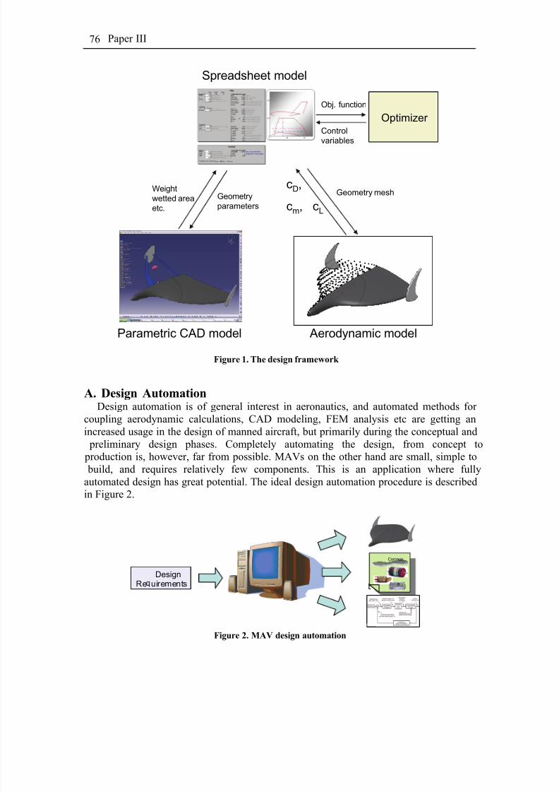
8/2/2019 K Amadori On Conceptual Aircraft Design
http://slidepdf.com/reader/full/k-amadori-on-conceptual-aircraft-design 90/101
Paper III76
Weight
wetted area
etc.
Geometry
parameters
Optimizer
Obj. function
Control
variables
Parametric CAD model Aerodynamic model
Spreadsheet model
Geometry meshcD,
cm, cL
Figure 1. The design framework
A. Design AutomationDesign automation is of general interest in aeronautics, and automated methods for
coupling aerodynamic calculations, CAD modeling, FEM analysis etc are getting anincreased usage in the design of manned aircraft, but primarily during the conceptual and preliminary design phases. Completely automating the design, from concept to production is, however, far from possible. MAVs on the other hand are small, simple to build, and requires relatively few components. This is an application where fullyautomated design has great potential. The ideal design automation procedure is describedin Figure 2.
Figure 2. MAV design automation
DesignRe uirements
Component List

8/2/2019 K Amadori On Conceptual Aircraft Design
http://slidepdf.com/reader/full/k-amadori-on-conceptual-aircraft-design 91/101
Distributed Framework for Micro Aerial Vehicle Design Automation 77
From a mission scenario a design specification is created. This is information such as performance, payload requirements etc. A design tool, such as the presented “designframework”, then uses several coupled computer software’s, to generate the following.
a. List of optimal propulsion system components. From a database of off the shelf
components. b. A full CAD model that is used for production. Production may beaccomplished in composite material, foam plastic, rapid prototyping etc.
c. Control scheme for Flight control system. Basically the configuration softwareto upload in the intended autopilot.
The current work focuses on task a. and b. while the control system optimizationrequires flight mechanical modeling and will be subject to future work.
Imagine for instance a scenario requiring a high quality live video, thermal imaging,and high resolution photos for object identification or geo localization. All these sensorsexist in sizes small enough to be carried on a MAV, but one MAV do not have the
payload capability to carry all at once. Using multiple MAVs carrying different sensors isan attractive solution. Due to different weights and sizes of these sensors it may bedifficult to design a MAV that can be adopted for each sensor while achieving proper stability and performance. This is an example where design automation could have agreat impact. Design automation allows a much more flexible way of using MAVs for missions previously solved by larger more expensive UAVs. For different scenarios onecan focus on what sensors to use rather then compromising on what sensors can beadapted to one existing platform.
II. Distributed Design Framework The design framework presented in this work has been created from the experience
gathered from the Modelith framework which was developed within the research group4
.The Modelith framework is based on Web Service Technology and implements as so-called Service Oriented Architecture (SOA)5. This architecture is based a set of standardsfor distributed computing developed by World Wide Web Consortium which enablesdistribution and integration of tools at the same time.
The interconnected modules communicate using standardized messages formattedaccording to the SOAP standard (Simple Object Access Protocol). These messagesinclude the transmitted data and instructions for which method to invoke on theconnected service. Each module is also described using WSDL (Web Service DescriptionLanguage). This description provides enough information to automatically create thecomputational interface between the modules. Please refer to Ref.4 and Ref.5 for a more
detailed and technical description.
A. Excel SpreadsheetThe base of the design framework is a user-friendly Excel spreadsheet. It serves as aninput interface for the different design variables, and also links together the calculations between CAD software and the Panel Code. In Excel the calculations of the different propulsion system components are made. Excel then calls the CAD software for weight

8/2/2019 K Amadori On Conceptual Aircraft Design
http://slidepdf.com/reader/full/k-amadori-on-conceptual-aircraft-design 92/101
Paper III78
calculations and the Panel Code for aerodynamic calculations. Lastly it calculates theMAV performance. The different parts of the excel program are shortly explained below.
1. GeometryIn Excel there is a simple to use geometry input module
which is used by the CAD program to update the parametric CAD model. In this module the MAV is definedas a tailless aircraft. The wing is defined by total area,aspect ratio, dihedral and twist angle. Two parameters arealso controlling the curvature of the leading and trailingedges, allowing the wing to be shaped with a “nontrapezoidal” contour. The wing profiles at the wing rootand tip can be chosen from a catalog and are controlledthrough two dedicated parameters.
The fuselage is completely blended with the wing andits size depends on the wing root length and thickness. It is
however possible to specify the cross section size andlength of the portion of the fuselage ahead of the wing.The fins are placed at the wing tips and their dimension
is defined by a tail volume coefficient. Other parametersthat can be set are sweep and taper ratio, plus a coefficientthat controls how the fins surface is distributed above and below the chord line. Figure 3shows a principal sketch of a typical geometry created in the geometry module.
Figure 3. MAV Geometry
The geometry includes also three different payload boxes and all control systemequipment. Each component is represented as a rectangular box of given length, height,width and weight, all taken from a database included in the spreadsheet. It is then possible to review their placement in order to balance the aircraft and to verify thateverything fits inside the outer surface.
2. PropulsionThe propulsion system consists of propeller, electric motor, PWM motor controller,
and battery (Fig. 4). Each component is modeled individually. The models used are briefly described below.
P
The propeller is modeled using blade element theory software by Hepperle7. Themodel gives an estimation of power coefficient Cp and thrust coefficient Ct as function of advance ratio v/nD. It requires geometric shape of the propeller together with informationof its airfoil along the blade radius. Accordingly to Hepperle the accuracy of the model is
ηη η
η
Po
Figure 4. MAV propulsion system.
ηtot=η b*ηd*η

8/2/2019 K Amadori On Conceptual Aircraft Design
http://slidepdf.com/reader/full/k-amadori-on-conceptual-aircraft-design 93/101
Distributed Framework for Micro Aerial Vehicle Design Automation 79
very god, when the power and thrust loading is relatively low, as in the case of MAV propellers.
The motor is described by the motor constants K v, I0 and R m. This is data that isusually given by motor manufacturers. A model of an electric motor using these constantsis shown in Figure 5. The electric motor has its rpm (n) proportional to motor EMF. K v is
the RPM proportionality constant. Losses in the motor are characterized by its internalresistance R m and no load current I0.
(W)
(W)
(W)
(rpm)
ω τ ⋅=
⋅=
⋅=
⋅=
out
emf out
mmin
vemf
P
U I P
U I P
K U nRm Im
This is a well known motor model and as long as the motor constants are defined
properly by the motor manufacturer, the accuracy of the model is very good for normaloperating conditions.
Modeling the losses in the motor controller is complex. The losses in the controller aredepending of several factors. According to Lawrence8, the main controller losses for lowinductance motors, such as the ones suitable for MAV:s, are due to the insufficientfiltering of the PWM harmonics. Lawrence presents a mathematical model that uses thePWM frequency, power setting, and motor inductance to estimate these losses. Thismodel has been implemented in the design tool.
Battery is modeled using its capacity C, rated nominal voltage U, and internalresistance R b. The total energy source (battery pack) consists of several battery cellscoupled in series and/or in parallel. The weight of the battery pack is the number of cells
multiplied by cell weight and with a correction for the weight of the material surroundingthe cells. This is material such as cable, connector and plastic wrapping.
For each component a large database has been created storing data from many off theshelf components used in hobby applications. To insure a broad spectrum of possibledesigns the database contains as much as 130motors, 15 motor controllers, 30 propellersand 30 batteries.
3. Weight and AerodynamicsThe weight prediction is carried out with the parametric CAD model of the aircraft,
while the aerodynamic performance calculation is done by a panel code. See more in thefollowing paragraph. The panel code used is considering only inviscid flows hence not
taking into account the viscosity effects. Skin friction drag is there fore calculated basedon the wetted area from the CAD software. Prandtl and von Karman equations for turbulent boundary layer have been used (ref. 6). Hoerner 6 equations have been used tocorrect skin friction for three-dimensional bodies.
4. PerformanceFrom the results of the CAD program weight predictions, the panel code aerodynamics
calculations, and propulsion system modeling, the performance is calculated. As results
I0 Um
emf M
I +
Figure 5. Model of electric motor.
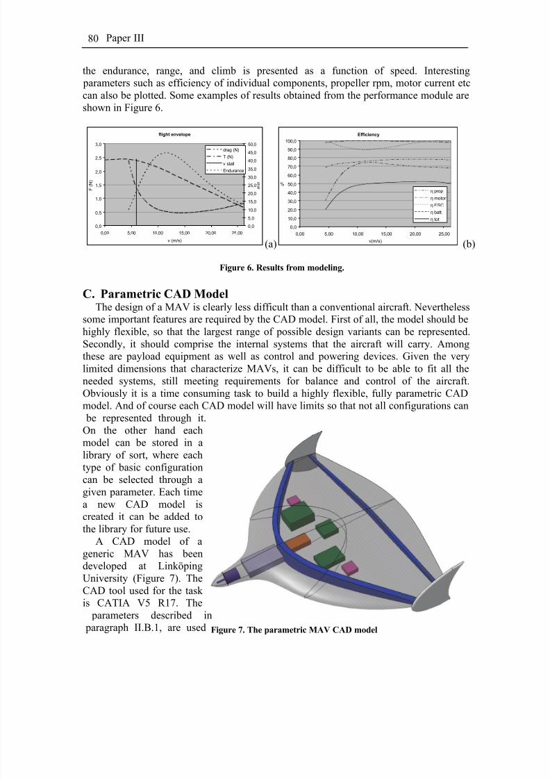
8/2/2019 K Amadori On Conceptual Aircraft Design
http://slidepdf.com/reader/full/k-amadori-on-conceptual-aircraft-design 94/101
Paper III80
the endurance, range, and climb is presented as a function of speed. Interesting parameters such as efficiency of individual components, propeller rpm, motor current etccan also be plotted. Some examples of results obtained from the performance module areshown in Figure 6.
flight envelope
0,0
0,5
1,0
1,5
2,0
2,5
3,0
0,00 5,00 10,00 15,00 20,00 25,00
v (m/s)
F ( N )
0,0
5,0
10,0
15,0
20,0
25,0
30,0
35,0
40,0
45,0
50,0
m i n
drag (N)
T (N)
v stall
Endurance
Efficiency
0,0
10,0
20,0
30,0
40,0
50,0
60,0
70,0
80,0
90,0
100,0
0,00 5,00 10,00 15,00 20,00 25,00
v(m/s)
%
η prop
η motor
η ESC
η batt
η tot
(a) (b)
Figure 6. Results from modeling.
C. Parametric CAD ModelThe design of a MAV is clearly less difficult than a conventional aircraft. Nevertheless
some important features are required by the CAD model. First of all, the model should behighly flexible, so that the largest range of possible design variants can be represented.Secondly, it should comprise the internal systems that the aircraft will carry. Amongthese are payload equipment as well as control and powering devices. Given the verylimited dimensions that characterize MAVs, it can be difficult to be able to fit all theneeded systems, still meeting requirements for balance and control of the aircraft.Obviously it is a time consuming task to build a highly flexible, fully parametric CAD
model. And of course each CAD model will have limits so that not all configurations can be represented through it.On the other hand eachmodel can be stored in alibrary of sort, where eachtype of basic configurationcan be selected through agiven parameter. Each timea new CAD model iscreated it can be added tothe library for future use.
A CAD model of ageneric MAV has beendeveloped at LinköpingUniversity (Figure 7). TheCAD tool used for the task is CATIA V5 R17. The parameters described in paragraph II.B.1, are used Figure 7. The parametric MAV CAD model

8/2/2019 K Amadori On Conceptual Aircraft Design
http://slidepdf.com/reader/full/k-amadori-on-conceptual-aircraft-design 95/101
Distributed Framework for Micro Aerial Vehicle Design Automation 81
to determine the outer surfaces in this model. Then the internal systems and structuralelements are placed within them. As previously explained the spreadsheet includescatalogues within which it is possible to choose the following components:
− Engine
− Speed regulator − Receiver − Servos− Autopilot− Camera− Video link
Since the aircraft is of very simple nature and of a very small size, the structuralrequirements are quite simple. The aircraft is designed to be manufactured as an outer shell of glass or carbon fiber which is more than enough to withstand all aerodynamicloads. Nevertheless a simple structure composed by two spars made of polystyrene
extending along the whole wing span is included. Their task is mainly to prevent the shellfrom buckling or collapsing inward when handling the aircraft, and at landing.
From the CAD model it is possible to retrieve a precise measure of the aircraft weight9 and mass distribution that can be used for both performance prediction as well as flightsimulations. Especially when compared to the previous method of calculating theexpected total weight (see Ref.1), the use of a CAD model represents a further improvement.
Finally, the outer surfaces of the MAV are discretized with a mesh, and the nodecoordinates are gathered to be sent to the panel code for aerodynamic analysis.
D. Panel Code
At the moment, the aerodynamic analysis tool adopted is a panel code, PANAIR.Panel codes are numerical schemes for solving (the Prandtl-Glauert equation) for linear,inviscid, irrotational flow about aircraft flying at subsonic or supersonic speeds10. As pointed out by Amadori et. al.2, panel codes are not as precise as modern CFDs can be, but they have other advantages. Considering that during a conceptual design phase, theaircraft geometry and its outer shape is not precisely defined and that the detail level isquite rough, it is clear that it can be unpractical and not justified to use tools that have amuch higher accuracy. Moreover CFDs requires the space around the studied body to beaccurately meshed, while for a panel code it is sufficient to approximate the aircraft’souter surfaces with proper rectangular panels. Therefore the meshing time required by a panel code is lower by several orders of magnitude, compared to a CFD code. When
much powerful and faster computers will be available or if higher accuracy was required,PANAIR could be substituted with other solvers, thanks to the modular nature of theframework.
The CAD model described here above is also responsible for generating a mesh of thesurfaces of the aircraft. This is performed by an in-house tool developed at LinköpingUniversity. This grid is then used by the panel code algorithm to calculate basicaerodynamic coefficients for a given mission section. The parameters that are required for an analysis to be carried out are angle of attack, yaw angle, air speed and altitude.

8/2/2019 K Amadori On Conceptual Aircraft Design
http://slidepdf.com/reader/full/k-amadori-on-conceptual-aircraft-design 96/101
Paper III82
Outputs of this module are lift coefficients c L and c Lα , induced drag coefficient cdi and pitching moment coefficients cm and cmα . PANAIR returns also the pressure values andspeed vectors in each node of the mesh that is input.
The analysis of one given configuration is carried out in two steps (Figure 8). FirstPANAIR is run at two different and arbitrary angles of attack, i.e. 1 and 6 degrees. The
only requirement here is that the angles must be within the linear range of the liftcoefficient. The results from this analysis permit to retrieve the slope of the c L -curve asfunction of the angle of attack (c Lα ). Given now the weight of the aircraft, its cruisingspeed and altitude, the cruising angle of attack α cruise is calculated. Then PANAIR is run asecond time at this specific angle of attack, in order to predict the induced dragcoefficient (cdi-cruise) in cruise condition. Moreover, the knowledge of three cdi –valuesenables to easily estimate the relationship between induced drag and angle of attack which is used for performance calculations other then at the cruise condition.
PANAIR run at
1 and 6 degrees
c Lc L,α
m·g = c L·S·q
c L = c L,α ·a + c L,α =0
m·g = c L·S·q
c L = c L,α ·a + c L,α =0
c L,cruisePANAIR run
at c L,cruise
c Di ( α )c Di,cruise
Figure 8. Each configuration is analyzed in two steps.
E. Optimization AlgorithmTwo different optimization algorithms can be used. First is a genetic algorithm that is
programmed as a macro add-in for Microsoft Excel. This algorithm has already proven to be successful for MAV-design optimization1. A second possibility is to adopt theComplex-RD algorithm. It is a modified variant of the Complex algorithm11,12,13 that iscapable of handling discrete variables together with continuous ones.
So far only the genetic algorithm has been tested, while the Complex algorithm hasonly been plugged in into the framework but any optimization has not been carried outyet.
III. Design Automation and OptimizationThe design optimization task comprises two different aspects: the optimization of the
aircraft shape and the optimization of the components of control and propulsion system.These can be run separately, in sequence or simultaneously. Every function evaluation becomes more time expensive when using CATIA and PANAIR to analyze the aircraftgeometry and aerodynamics. Thus it is possible to select whether the framework shoulduse them or not for computing weight, center of gravity location, lift and dragcoefficients. Figure 5 shows the information flow within the framework. The scheme
shows clearly where the new module has been inserted and how it now possible to choose between calculating weight and induced drag by means of CATIA and PANAIR or not.

8/2/2019 K Amadori On Conceptual Aircraft Design
http://slidepdf.com/reader/full/k-amadori-on-conceptual-aircraft-design 97/101
Distributed Framework for Micro Aerial Vehicle Design Automation 83
Geometry
Definition
Propulsion System
Definition
Weight
Thrust
Parasite DragInduced Drag
Performance
Prediction
CATIA
PANAIR Lifting-Line Theory
Figure 9. Information flow within the framework.
Since each function evaluation involving the new module containing CATIA andPANAIR takes between 10 and 40 seconds, depending mostly on how many parametersare changed from the previous configuration, the design optimization has been dividedinto two successive parts. First the framework is run without invoking the new module.This ensures much more rapid iterations at the cost of less accurate results. In this initialmode, a large number of parameters are involved in the optimization which comprises both the geometry layout of the aircraft as well as the selection of the propulsion system.When convergence is reached the system is restarted, this time involving CATIA andPANAIR, using the optimum solution obtained as starting point. The propulsion system
is frozen and the geometric design parameters are allowed to vary within a narrower range. In this second phase design parameters that could not be evaluated using thelifting-line theory can be included, such as the tip chord twist or the wing profile.
If the result from the second optimization would not agree with the first one, the whole process is repeated until convergence between the results is reached. The process isillustrated in Figure 10.
Optimization(If geometry changes
significantly)
Optimization
Fast
Simplegeometric andaerodynamic
model
Fast
System and performancemodels
Optimization
Expensive
Complexgeometric andaerodynamic
model
Geometry
(continuous)
System parameters
(discrete and
continuous )
Geometry
(continuous)
System parameters
(discrete and
continuous)
Fast
System and performancemodels
Figure 10. Optimization procedure.
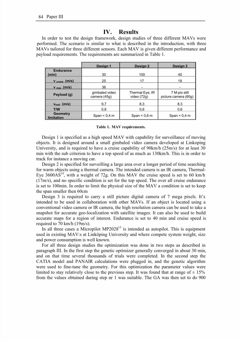
8/2/2019 K Amadori On Conceptual Aircraft Design
http://slidepdf.com/reader/full/k-amadori-on-conceptual-aircraft-design 98/101
Paper III84
IV. ResultsIn order to test the design framework, design studies of three different MAVs were
performed. The scenario is similar to what is described in the introduction, with threeMAVs tailored for three different sensors. Each MAV is given different performance and payload requirements. The requirements are summarized in Table 1.
Design 1 Design 2 Design 3
Endurance(min) 30 100 40
v cruise (m/s) 25 17 19
v max (m/s) 36 - -
Payload (g)gimbaled video
camera (45g)Thermal Eye, IRvideo (72g)
7 M-pix stillpicture camera (60g)
vstall (m/s) 9,7 8,3 8,3
T/W 0,8 0,6 0,6
Geometry
limitation
Span < 0,4 m Span < 0,6 m Span < 0,4 m
Table 1. MAV requirements.
Design 1 is specified as a high speed MAV with capability for surveillance of movingobjects. It is designed around a small gimbaled video camera developed at LinkopingUniversity, and is required to have a cruise capability of 90km/h (25m/s) for at least 30min with the sub criterion to have a top speed of as much as 130km/h. This is in order totrack for instance a moving car.
Design 2 is specified for surveilling a large area over a longer period of time searchingfor warm objects using a thermal camera. The intended camera is an IR camera, Thermal-Eye 3600AS14, with a weight of 72g. On this MAV the cruise speed is set to 60 km/h
(17m/s), and no specific condition is set for the top speed. The over all cruise enduranceis set to 100min. In order to limit the physical size of the MAV a condition is set to keepthe span smaller then 60cm
Design 3 is required to carry a still picture digital camera of 7 mega pixels. It’sintended to be used in collaboration with other MAVs. If an object is located using aconventional video camera or IR camera, the high resolution camera can be used to take asnapshot for accurate geo-localization with satellite images. It can also be used to buildaccurate maps for a region of interest. Endurance is set to 40 min and cruise speed isrequired to 70 km/h (19m/s).
In all three cases a Micropilot MP202815 is intended as autopilot. This is equipmentused in existing MAV:s at Linköping University and where compete system weight, size
and power consumption is well known.For all three design studies the optimization was done in two steps as described in
paragraph III. In the first step the genetic optimizer generally converged in about 30 min,and on that time several thousands of trials were completed. In the second step theCATIA model and PANAIR calculations were plugged in, and the genetic algorithmwere used to fine-tune the geometry. For this optimization the parameter values werelimited to stay relatively close to the previous step. It was found that at range of ± 15%from the values obtained during step nr 1 was suitable. The GA was then set to do 900

8/2/2019 K Amadori On Conceptual Aircraft Design
http://slidepdf.com/reader/full/k-amadori-on-conceptual-aircraft-design 99/101
Distributed Framework for Micro Aerial Vehicle Design Automation 85
function evaluations and report the optimal configuration. With a population size of 20individuals this represents 45 generations. Although this may not be a fully convergedsystem it is well within the accuracy of the models, and spending more time to improvethe optimum does not make sense. Another reason not to use more function evaluations isthat a memory leak in CATIA slowly decreases the available memory to a point where
the system finally crashes.During the optimization the objective was set to keep the weight as low as possiblewhile having criteria’s, in the form of penalty functions, for endurance, stall speed, etc (asdefined in Table 1). This insures to design the smallest possible MAV that fulfills therequirements. This is different from the optimization in ref 1, where the MAV endurancewas optimized while keeping the geometrical size within restricted values.
The result of the three design studies has been very successful. Suitable propulsionsystems were chosen and the over all plan forms generated give a god impression. Theobjectives defined in Table 1 were all met. Agreement between lifting line theory and panel code is generally quite good. The design does not change much between step 1 and
2. In beginning the panel code had a tendency to reduce the wing sweep found in the firstoptimization. Since the winglets are mounted on the wing tips, and defined by tail volumecoefficient, this lead to winglets of large area and height, but small cord. Apparently theoptimizer found that the reduction in induced drag was grater then the increase of parasitedrag, but the winglets generated would be fragile and not viable for practical use. Toavoid this problem a penalty function was added that penalized the objective function if the winglet grew to much in height.
Table 2 below summarizes the results of the 3 different designs.
Design 1 “high speed”Design 2 “longendurance”
Design 3 “generalMAV”
Weight 387 g 616 g 426 g
Span 365 mm 595 mm 353 mmStallspeed 9,6 m/s 8,2 m/s 8,3 m/s
T/W ratio 0,80 0,78 0,80
Endurance at cruise 32,3 min 101,1 min 46,1 min
Maxspeed 35,9 m/s 27,2 m/s 24,6 m/s
Motor Apache 20-34T Mfly 180-08-11 Mfly 180-08-15
Controller YGE 8 YGE8 YGE 8
Battery Thunderpower 2000mAh 3s1p Tanic 2200mAh 3s2p Thunderpower 2000mAh 3s1p
Propeller APC 6x6.9 (repitched 6x5.5) APC electric 6x4 APC electric 6x4
Table 2. Result from design optimization

8/2/2019 K Amadori On Conceptual Aircraft Design
http://slidepdf.com/reader/full/k-amadori-on-conceptual-aircraft-design 100/101
Paper III86
It can be noted that a few propulsion system components was chosen for several of thedesigns. For instance all got the same controller. None of the designs got the same motor, but design 2 and 3 got the same propeller. That is a bit surprising, but is probably a fact of that the design space is discrete, and not enough propellers are available in the database.Design 1 and 3 also got the same batteries. This is a result of that particular battery
having the highest energy density in the database and the optimizer tend to find theoptimal components and fine tune the geometry to fit this system.
V. Future DevelopmentThe design framework is a helpful tool in MAV design, but there are two important
issues, that for time constraints were not dealt with in this paper. That is to insure thatduring the optimization, the proper balance and size restrictions are met. The MAV musthave large enough volume to accommodate its intended components, as well as balancewith a proper stability margin. Controlling that a component fits can easily be done bymeasuring directly in the CAD model. If each component is defined with dimensions inthe database, a script can be made that automatically controls if the component fits, by
measuring the distance between the upper and lower wing surface in CATIA at eachcorner of the component. Ensuring that balance is achieved can then be done in two ways.The easiest method to implement is to manually place the components in a fixed pattern,and let the GA evolve the airframe around that pattern, with a penalty function if the balance criterion is not met. The other option is to have an inner loop that for eachfunction evaluation seeks to adjust the component positions to where the balance criteriais met. The use of CATIA and PANAIR is of great help here as one tool gives the pitching moment and neutral point, and the other gives the center of gravity.
As always when working with theoretical models, validation is needed before theresult can be trusted. The PANAIR code was developed for larger manned aircraft and isnot necessarily the ideal tool for MAV design. A correlation with wind tunnel data is
needed. It should be clearly pointed out that this paper is demonstrating the possibilitieswhen combining CAD with panel code in design automation. PANAIR could easily bereplaced with a different code more suitable for the task. Preferably CFD should be usedfor aerodynamics calculations, but still that is far too computationally heavy to use inoptimization. It would however be interesting to use CFD as a last step of the designautomation to get a better view of the final aerodynamics.
References1Lundström, D., Krus, P., “ Micro Aerial Vehicle Design Optimization Using Mixed
Discrete and Continuous Variables”, 11th AIAA/ISSMO Multidisciplinary Analysis andOptimization Conference, Sept. 2006, Portsmouth, VA, USA
2Amadori, K., Jouannet, C., Krus, P., ”Use of Panel Code Modelling in a Framework for Aircraft Concept Optimization”, 11th AIAA/ISSMO Multidisciplinary Analysis andOptimization Conference, Sept. 2006, Portsmouth, VA, USA
3Amadori, K., Johansson, B., Krus, P., ”Uing CAD Tools and Aerodynamic Codes in a
Distributed Conceptual Design Framework ”, 45th AIAA Aerospace Sciences Meetingand Exhibit, Jan. 2007, Reno, NV, USA
4Johansson, B., Jouannet, C., Krus, P., ” Distributed Aircraft Analysis Using WebService Technology”, World Aviation Congress ® & Exposition, Linköping, 2003.
8/2/2019 K Amadori On Conceptual Aircraft Design
http://slidepdf.com/reader/full/k-amadori-on-conceptual-aircraft-design 101/101
Distributed Framework for Micro Aerial Vehicle Design Automation 87
5Tsalgatidou A. and Pilioura T., " An Overview of Standards and Related Technology
in Web Services", Distributed and Parallel Databases, 12, 2002.6 F. Hoerner, “ Fluid Dynamic Drag: Practical Information on Aerodynamic Drag
and Hydrodynamic Resistance”, Midland Park, N.J. 19657M. Hepperle, ”Java Prop - propeller analysis”, URL: www.mh-aerotools.de8
D. Lawrence, K. Mohseni, “Efficiency Analysis for Long-Duration Electric MAVs”,AIAA Infotech Aerospace, Arlington, Virginia, September, 26-28, 2005, AIAA 2005-7090
9Jouannet, C., Silva, S.E.R., Krus, P., “Use Of CAD For Weight Estimation In Aircraft
Conceptual Design”, 24th International Congress Of The Aeronautical Sciences,Linköping University, Linköping, Sweden, 2004.
10Erikson, L.L., “ Panel Methods – An Introduction”, NASA Technical Paper 2995,1990
11Andersson, J., “ Design Optimization”, Linköping University, Linköping, Sweden,2005.
12Krus, P., Andersson, J., “ An Information Theoretical Perspective On Design
Optimization”, Design Engineering Technical Conference, Salt Lake City, UT, USA,2004.13Krus, P., Andersson, J., “Optimizing Optimization for Design Optimization”,
DETC’03 2003 ASME Design Engineering Technical Conferences and Computers andInformation in Engineering Conference, Chicago, IL, USA, 2003.
14 www.thermal-eye.com15 www.micropilot.com