k2.1 k3 - thetford.com · k3.2 (2x) tornillos autoperforantes, arandelas. 5 sani-con turbo...
TRANSCRIPT

Form/Formulaire/Formulario No. 97591 Rev. A 12.20.161
Part No.No de pièce 97585,
97589, No. de piezaP.O. Box 1285Ann Arbor, MI 48106
www.thetford.comSani-Con® Turbo Made in the U.S.A. Fabriqué aux É.-UHecho en EE. UU.
Permanent Storage Box
Tools Needed: ■ Drill Bit Size H (17/64), #12/14 ■ Hex Head Screw Driver ■ Drill Bit #7 (13/64) ■ Phillips Screwdriver ■ Power Drill
Questions?If you have any questions or need assistance, please contact Techni-cal Support at 1-800-444-7210, available Monday through Friday 8 a.m. to 6 p.m., Eastern Standard Time.
Warnings and CautionsRead and understand the warnings and cautions listed in this docu-ment before you install or operate this unit.
Read and understand the warnings listed in this document before you install, operate, or service this system. If you do not obey these warnings there is a risk of property loss, injury, or electrocution. Do not make any changes to this unit as this could result in property damage, injury, or electrocution.
Thetford Corporation accepts no responsibility or liability for damage to equipment, injury, or death that may result from the system's improper installation, service, or operation.
Thetford Corporation recommends that plumbing and electrical work be performed by a licensed tradesperson. Local permit and code compliance is required.
NOTICEAVISAVISOCAUTION! ATTENTION! ATTENTIONATTENTION! ATENCIÓNATTENTION! DANGER
Be sure installation screws are at least 1/4” from gas line to ensure vibration does not allow friction between gas line and screw. Refer to Fig. 3.
Do not make any changes to this unit, as this could result in property damage or injury.
NOTICEAVISAVISOCAUTION!
■ Placement of the hose connection MUST be service-able by the customer.
■ Ensure the hose is able to reach the box when plan-ning the installation.
General Guidelines Weight placed in box cannot exceed 25 pounds.NOTICEAVISAVISOCAUTION! ATTENTION! ATTENTIONATTENTION! ATENCIÓNATTENTION! DANGER
Plumbing from pump to storage compart-ment MUST be plumbed with Schedule 30, 40, 80, or DWV rated hard pipe fittings or minimum 10 PSI flexible pipe rating for pressure side of pump.
Plan for sufficient clearance under the RV once the box mount is installed. Lowest point of unit MUST be above axles of coach.
Plan the installation so the box A is flush (or recessed) with the side of the RV.
To avoid damage to the hose, it is impor-tant to make sure ALL screws used to secure the box are inserted in the flange J of the box A, not the box itself!
NOTICEAVISAVISOCAUTION!
Ref. Description
K1 (1x) Permanent Storage Box K1.1 Flange on Storage Box
K2 (2x) Angle BracketsK2.1 (4x) Washers, Screws, NutsK2.2 (4x) Self Drilling Screws, Washers
K3 (2x) I-Beam Brackets,K3.1 (2x) Washers, Screws, NutsK3.2 (2x) Self Drilling Screws, Washers
Parts: K1 - K3
K1K1.1
K2
K3K2.1
K2.2
K3.2
K3.1

Sani-Con Turbo Permanent Storage Box 2 www.thetford.com
Box Installation Planning
Plan the installation so that A is flush (or recessed) with H. Refer to Fig. 1. NOTICEAVISAVISOCAUTION!
Installations near the gas line MUST be po-sitioned so that screws are at least .25” from the gas line. Refer to Fig. 3.
NOTICEAVISAVISOCAUTION! ATTENTION! ATTENTIONATTENTION! ATENCIÓNATTENTION! DANGERRef. Ref. DescriptionA. K1 Permanent Storage Box
A1. K1,1 Flange on Storage Box
B. K2 Angle Brackets
C. K3 I-Beam BracketsK3.2 (2x) Self Drilling Screws, Washers
D. A Optional RV Drain for manual override
E. B Gate Valve
F. C Plumbing (Hard or flexible pipe) to discharge hose
G. D 1.5” Discharge Hose / (G1) Hose Barb (FIG 4)
H. E RV Skirting
I. F RV I-Beam
J. G Gas Pipe (if applicable)
Fig. 3
T000
089A
G
F !
K3
K1
K2
Fig. 1
T000
089A
AB
E F
!C
D
K1
Fig. 2
A1
T000
089A
F
B2
K3
K2
K1.1 K1
K3.2
Sani-Con Turbo Permanent Storage Box3www.thetford.com
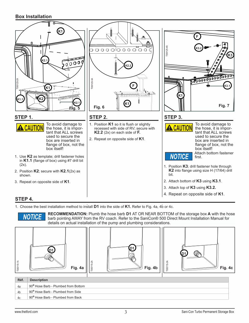
1. Choose the best installation method to install D1 into the side of K1. Refer to Fig. 4a, 4b or 4c.
D1
1. Position K3; drill fastener hole through K2 into flange using size H (17/64) drill bit.
2. Attach bottom of K3 using K3.1.
3. Attach top of K3 using K3.2.4. Repeat on opposite side of K1.
STEP 3.
Attach bottom fastener first.NOTICE
T000
115-
3A
Fig. 4b Fig. 4c
D1
To avoid damage to the hose, it is impor-tant that ALL screws used to secure the box are inserted in flange of box, not the box itself!
NOTICEAVISAVISOCAUTION!
Box Installation
STEP 2.
STEP 4.
T000
115-
1A
T000
115-
2A
Fig. 4a
D1
RECOMMENDATION: Plumb the hose barb D1 AT OR NEAR BOTTOM of the storage box A with the hose barb pointing AWAY from the RV coach. Refer to the SaniCon® 500 Direct Mount Installation Manual for details on actual installation of the pump and plumbing considerations.
NOTICE
STEP 1.1. Position K1 so it is flush or slightly
recessed with side of RV; secure with K2.2 (2x) on each side of F.
2. Repeat on opposite side of K1.
1. Use K2 as template; drill fastener holes in K1.1 (flange of box) using #7 drill bit (2x).
2. Position K2; secure with K2.1(2x) as shown.
3. Repeat on opposite side of K1.
To avoid damage to the hose, it is impor-tant that ALL screws used to secure the box are inserted in flange of box, not the box itself!
NOTICEAVISAVISOCAUTION!
Réf. Description
4a 90o Hose Barb - Plumbed from Bottom
4b 90o Hose Barb - Plumbed from Side
4c 90o Hose Barb - Plumbed from Back
Fig. 5
F
Fig. 7
T000
125-
4A
STEP 1.
K1
T000
125-
2A
F
Fig. 6
T000
125-
3A
K2.1
K1
K1.1 K2K2.1
K2.2
K1
K3.2
K3
K3.1
K1

Part No.No de pièce 97585,
97589, No. de piezaP.O. Box 1285Ann Arbor, MI 48106
www.thetford.comSani-Con® Turbo
Form/Formulaire/Formulario No. 97591 Rev. A 12.20.164
Made in the U.S.A. Fabriqué aux É.-UHecho en EE. UU.
Coffre de rangement permanent
Outils requis : ■ Mèche H (17/64 po), n° 12/14 ■ Tournevis à tête hexagonale ■ Mèche n° 7 (13/64 po) ■ Tournevis cruciforme ■ Perceuse
Caja de almacenamiento permanente
Prenez connaissance des avertissements et des mises en garde figurant dans ce document avant d’installer, d’utiliser ou d’entretenir ce système. Ignorer ces avertissements peut conduire à des pertes matérielles, des blessures ou une électrocution. N’apportez aucune modification à cette unité au risque de causer des dommages matériels, des blessures ou une électrocution.
Thetford Corporation décline toute responsabilité relative à des dommages matériels, blessures ou mortalités découlant d’une installation, d’une réparation ou d’une utilisation incorrecte de ce système.
Thetford Corporation recommande que les travaux de plomberie et d’électricité soient exécutés par un professionnel muni d’une licence. Un permis local et le respect du code sont exigés.
NOTICEAVISAVISOCAUTION! ATTENTION! ATTENTIONATTENTION! ATENCIÓNATTENTION! DANGERATTENTION! DANGER
Herramientas necesarias: ■ Broca de tamaño H (17/64), #12/14 ■ Destornillador de cabeza hexagonal ■ Broca #7 (13/64) ■ Destornillador Phillips ■ Taladro
Lea y comprenda las advertencias contenidas en este documento antes de instalar, hacer funcionar o dar mantenimiento a este sistema. El incumplimiento de estas advertencias dará lugar a riesgos de pérdidas materiales, lesiones o electrocución. No modifique de ninguna manera esta unidad pues, de hacerlo, podría ocasionar daños materiales, lesiones o electrocución.
Thetford Corporation no admite ninguna obligación o responsabilidad por cualquier daño al equipo, lesiones o muertes que pudieran resultar de la instalación, el servicio o el manejo incorrectos de este sistema.
Thetford Corporation recomienda que los trabajos eléctricos y de plomería sean realizados por personal con licencia. Se requiere el cumplimiento de los códigos y permisos municipales.
ATTENTION! PELIGRO
K1K1.1
K2
K3K2.1
K2.2
K3.2
K3.1
Pièces : K1 - K3 Piezas: K1 - K3
Réf. Description
K1 (1x) Coffre de rangement permanent K1.1 lèvre de fixation du coffre
K2 (2x) cornières,K2.1 (4x) rondelles, vis, écrous, K2.2 (4x) vis autoperforeuses, rondelles
K3 (2x) pattes de fixationK3.1 (2x) rondelles, vis, écrous, K3.2 (2x) vis autoperforeuses, rondelles
Réf. Descripción
K1 (1x) Caja de almacenamiento permanente K1.1 Reborde de la caja
K2 (2x) Soportes angularesK2.1 (4x) arandelas, tornillos, tuercas, K2.2 (4x) tornillos autoperforantes, arandelas
K3 (2x) Soportes de viga en doble T,K3.1 (2x) arandelas, tornillos, tuercasK3.2 (2x) tornillos autoperforantes, arandelas

Sani-Con Turbo Permanent Storage Box5www.thetford.com
Des questions?Pour toute question ou assistance, veuillez contacter le Service technique au 1-800-444-7210, du lundi au vendredi, de 8 h à 18 h, Heure normale de l’Est.
Assurez-vous que les vis de montage sont à au moins 6 mm des conduites de gaz afin que les vibrations ne puissent entraîner une friction entre les conduites et les vis. Reportez-vous à la fig. 3.
N’apportez aucune modification à cette unité au risque de causer des dommages matériels ou des blessures.
La tuyauterie entre la pompe et le compartiment du réservoir DOIT utiliser des raccords de tuyau rigide de catégorie 30, 40, 80 ou de drain, ou du tuyau flexible d’une résistance nominale d’au moins 10 PSI du côté pressurisé de la pompe.
Prévoyez suffisamment d’espace sous le VR une fois le coffre installé. Le point le plus bas de l’unité DOIT être situé au-dessus des essieux du véhicule.
Planifiez l’installation de sorte que le coffre A soit de niveau avec la paroi du VR (ou en retrait).
NOTICEAVISAVISOCAUTION! ATTENTION! ATTENTION
■ Les raccords de tuyauterie DOIVENT être disposés de manière à être accessibles par le client.
■ En planifiant l’installation, assurez-vous que le tuyau puisse atteindre le coffre.
Directives générales
Pour éviter d’endommager le tuyau, il est important de s’assurer que TOUTES les vis de montage du coffre soient insérées dans la lèvre de fixation J du coffre A, et non dans le coffre même!
¿Preguntas?Si tiene preguntas o necesita ayuda, llame al Departamento de Soporte Técnico al teléfono 1-800-444-7210 de lunes a viernes de 8 a. m. a 6 p. m. (hora del Este de Estados Unidos).
Asegúrese de que los tornillos de instalación estén a no menos de 6 mm (1/4”) de la tubería de gas para evitar que la vibración cause fricción entre la tubería de gas y el tornillo. Consulte la fig. 3.
No modifique de manera alguna esta unidad, pues de hacerlo podría ocasionar daños materiales o lesiones.
La instalación de la tubería de la bomba al compartimiento de almacenamiento TIENE QUE hacerse con conectores de tubería dura tipo DWV o cédula 30, 40 u 80, o tubería flexible con capacidad nominal de 10 PSI (mínimo) para el lado a presión de la bomba.
Tome previsiones para que haya suficiente espacio debajo del vehículo de recreo una vez que el montaje de caja esté instalado. El punto más bajo de la unidad TIENE QUE estar por encima de los ejes del vehículo.
Planifique la instalación de manera que la caja A esté a nivel (o embutida) con el lado del vehículo de recreo.
Para evitar dañar la manguera, es importante que TODOS los tornillos utilizados para asegurar la caja se inserten en el reborde J de la caja A ¡y no en la caja misma!
NOTICEAVISAVISOCAUTION! ATTENTION! ATTENTIONATTENTION! ATENCIÓN
■ La conexión de la manguera TIENE QUE estar ubicada en un lugar accesible por el cliente para fines de servicio.
■ A planificar la instalación, asegúrese de que manguera pueda llegar hasta la caja.
Pautas generales
Le poids placé dans le coffre ne doit pas dépasser 11 kg.NOTICEAVISAVISOCAUTION! ATTENTION! ATTENTIONATTENTION! ATENCIÓNATTENTION! DANGER
Avertissements et mises en gardePrenez connaissance des avertissements et des mises en garde figurant dans ce document avant d’installer ou d’utiliser cette unité.
La caja no puede soportar pesos mayores de 11 kg (25 libras).ATTENTION! PELIGRO
Advertencias y precaucionesLea y entienda las advertencias y precauciones contenidas en este documento antes de instalar o de hacer funcionar esta unidad.

Sani-Con Turbo Permanent Storage Box 6 www.thetford.com
Planification de l’installation du coffre Planificación de la instalación de la caja
Réf. DescriptionK1 Coffre de rangement permanent
K1,1 Lèvre de fixation du coffre de rangement
K2 Cornières de montage
K3 Pattes de fixation du profilé en IK3.2 (2x) vis autoperforeuses, rondelles
A Tuyau de drain facultatif du VR pour purge manuelle
B Robinet de purge
C Tuyauterie (rigide ou flexible) vers le tuyau d'évacuation
D Tuyau d’évacuation de 3,8 cm / raccord cannelé (G1) (Fig. 4)
E Jupe du VR
F Profilé en I du VR
G Tuyau de gaz (s'il y a lieu)
Ref. DescripciónK1 Caja de almacenamiento permanente
K1,1 Reborde en la caja de almacenamiento
K2 Soportes angulares
K3 Soportes de viga en doble TK3.2 (2x) tornillos autoperforantes, arandelas
A Desagüe del vehículo de recreo opcional para mando manual
B Válvula de compuerta
C Tubo (duro o flexible) a la manguera de descarga
D Manguera de descarga de 3.8 cm (1.5”) / Conector de manguera (G1) (fig. 4)
E Faldón del vehículo de recreo
F Viga en doble T del vehículo de recreo
G Tubo de gas (si corresponde)
Fig. 3
T000
089A
G
F !
K3
K1
K2
Fig. 1
T000
089A
AB
E F
!C
D
K1
Fig. 2
A1
T000
089A
F
B2
K3
K1.1 K1
K3.2
K2.2

Sani-Con Turbo Permanent Storage Box7www.thetford.com
1. Positionnez K3; percez un trou à trav-ers K2 dans la lèvre de fixation au moyen de la mèche H (17/64 po).
2. Fixez le bas de K3 à l’aide de K3.1.
3. Fixez le haut de K3 avec K3.2.4. Faites de même pour le côté opposé de
K1.
ÉTAPE 3.
Posez la vis du bas en premier.AVIS
T000
115-
3A
Fig. 4b Fig. 4c
D1
Pour éviter d’endommager le tuyau, il est important de s’assurer que TOUTES les vis de montage du coffre soient insérées dans la lèvre de fixation et non dans le coffre même!
NOTICEAVISAVISOCAUTION! ATTENTION! ATTENTION
Installation du coffre
1. Choisissez la meilleure méthode d’installation pour poser G1 sur le côté de A. Reportez-vous à la Fig. 4a, 4b ou 4c.
ÉTAPE 2.
ÉTAPE 4.
T000
115-
1A
T000
115-
2A
Fig. 4a
D1 D1
CONSEIL : Installez le raccord cannelé du tuyau D1 EN BAS OU PRÈS DU BAS du coffre de rangement A, en le pointant vers L’EXTÉRIEUR du VR. Consultez le Manuel d’installation du modèle SaniCon® 500 à montage direct pour plus de détails sur la méthode d’installation de la pompe et les questions de tuyauterie.
AVIS
ÉTAPE 1.1. Positionnez le coffre K1 de sorte qu’il
soit de niveau avec la paroi du VR ou légèrement en retrait; fixez-le avec K2.2 (2x) de chaque côté de F.
2. Faites de même pour le côté opposé de K1.
1. Utilisez K2 comme un gabarit; percez les trous de fixation dans K1.1 (lèvre du coffre) à l’aide de la mèche n° 7 (2x).
2. Positionnez une cornière K2; fixez-la avec K2.1 (2x) tel qu’illustré.
3. Faites de même pour le côté opposé de K1.
Pour éviter d’endommager le tuyau, il est important de s’assurer que TOUTES les vis de montage du coffre soient insérées dans la lèvre de fixation et non dans le coffre même!
NOTICEAVISAVISOCAUTION! ATTENTION! ATTENTION
Réf. Description
4a Raccord de tuyau de 90o - Installé dans le bas
4b Raccord de tuyau de 90o - Installé sur le côté
4c Raccord de tuyau de 90o - Installé dans le fond
Fig. 5
F
Fig. 7
T000
125-
4A
STEP 1.
K1
T000
125-
2A
F
Fig. 6
T000
125-
3A
K2.1
K1
K1.1 K2K2.1
K2.2
K1
K3.2
K3
K3.1
K1

Sani-Con Turbo Permanent Storage Box 8 www.thetford.com
1. Coloque K3; perfore un orificio de sujeción a través de K2 en el reborde, usando la broca H (17/64).
2. Conecte la parte inferior de K3 con K3.1.
3. Conecte la parte superior de K3 con K1.2.
4. Repita en el lado opuesto de K1.
PASO 3.
Ponga primero el tornillo del fondo.AVISO
T000
115-
3A
Fig. 4b Fig. 4c
G1
Para evitar dañar la manguera, es importante que TODOS los tornillos utilizados para asegurar la caja se inserten en el reborde de la caja, ¡y no en la caja misma!
NOTICEAVISAVISOCAUTION! ATTENTION! ATTENTIONATTENTION! ATENCIÓN
Instalación de la caja
1. Elija el mejor método de instalación para instalar G1 en el lado de A. Consulte las figuras 4a, 4b o 4c.
PASO 2.
T000
115-
1A
T000
115-
2A
Fig. 4a
G1 G1
RECOMENDACIÓN: Instale el conector de manguera G1 EN O CERCA DEL FONDO de la caja de almacenamiento A, con el conector de manguera apuntando en dirección OPUESTA al vehículo de recreo. Para obtener información sobre la instalación real de la bomba y sobre la plomería, consulte el Manual de instalación de SaniCon® 500 de montaje directo.
AVISO
PASO 1.1. Coloque K1 de manera que esté a nivel
(o ligeramente embutida) con el lado del vehículo de recreo; asegúrela con K2.2 (2x) en cada lado de F.
2. Repita en el lado opuesto de K1.
1. Use K2 como plantilla; perfore orificios de sujeción en K1.1 (reborde de la caja) usando la broca #7 (2x).
2. Coloque K2; asegúrelo con K2.1 (2x), tal como se muestra.
3. Repita en el lado opuesto de K1.
Para evitar dañar la manguera, es importante que TODOS los tornillos utilizados para asegurar la caja se inserten en el reborde de la caja, ¡y no en la caja misma!
NOTICEAVISAVISOCAUTION! ATTENTION! ATTENTIONATTENTION! ATENCIÓN
Ref. Descripción
4a Conector de manguera de 90o (instalado en el fondo)
4b Conector de manguera de 90o (instalado en el lado)
4c Conector de manguera de 90o (instalado atrás)
Fig. 5
F
Fig. 7
T000
125-
4A
STEP 1.
K1
T000
125-
2A
F
Fig. 6
T000
125-
3A
K2.1
K1
K1.1 K2K2.1
K2.2
K1
K3.2
K3
K3.1
K1
PASO 4.