k9a2gm / k9a2vm - ch · pdf filei g52-75011x7 ms-7501 (v1.x) mainboard k9a2gm / k9a2vm...
TRANSCRIPT
i
G52-75011X7
MS-7501 (V1.X) Mainboard
K9A2GM / K9A2VM
PDF created with pdfFactory Pro trial version www.pdffactory.com

ii
Copyright Notice
The material in this document is the intellectual property of MICRO-STARINTERNATIONAL. We take every care in the preparation of this document, but noguarantee is given as to the correctness of its contents. Our products are undercontinual improvement and we reserve the right to make changes without notice.
Trademarks
All trademarks are the properties of their respective owners.
NVIDIA, the NVIDIA logo, DualNet, and nForce are registered trademarks or trade-marks of NVIDIA Corporation in the United States and/or other countries.AMD, Athlon™, Athlon™ XP, Thoroughbred™, and Duron™ are registered trade-marks of AMD Corporation.Intel® and Pentium® are registered trademarks of Intel Corporation.PS/2 and OS®/2 are registered trademarks of International Business MachinesCorporation.Windows® 2000/NT/XP/Vista are registered trademarks of Microsoft Corporation.Netware® is a registered trademark of Novell, Inc.Award® is a registered trademark of Phoenix Technologies Ltd.AMI® is a registered trademark of American Megatrends Inc.
Revision History
Revision Revision History DateV1.0 First release August 2008
Technical Support
If a problem arises with your system and no solution can be obtained from the user’smanual, please contact your place of purchase or local distributor. Alternatively,please try the following help resources for further guidance.
Visit the MSI website for FAQ, technical guide, BIOS updates, driver updates,and other in f ormat ion: ht tp: / /g lobal .msi.com.tw/ index.php?func=serviceContact our technical staff at: http://ocss.msi.com.tw
PDF created with pdfFactory Pro trial version www.pdffactory.com

iii
Safety Instructions
CAUTION: Danger of explos ion if bat tery is incorrectly replaced.Replace only with the same or equivalent type recommended by themanufacturer.
1. Always read the safety instructions carefully.2. Keep this User’s Manual for future reference.3. Keep this equipment away from humidity.4. Lay this equipment on a reliable f lat surface before setting it up.5. The openings on the enclosure are for air convection hence protects the equip-
ment from overheating. DO NOT COVER THE OPENINGS.6. Make sure the voltage of the power source and adjust properly 110/220V be-
fore connecting the equipment to the power inlet.7. Place the power cord such a way that people can not step on it. Do not place
anything over the power cord.8. Always Unplug the Power Cord before inserting any add-on card or module.9. All cautions and warnings on the equipment should be noted.10. Never pour any liquid into the opening that could damage or cause electrical
shock.11. If any of the following situations arises, get the equipment checked by service
personnel:Ü The power cord or plug is damaged.Ü Liquid has penetrated into the equipment.Ü The equipment has been exposed to moisture.Ü The equipment does not work well or you can not get it work according to
User’s Manual.Ü The equipment has dropped and damaged.Ü The equipment has obvious sign of breakage.
12. DO NOT LEAVE THIS EQUIPMENT IN AN ENVIRONMENT UNCONDITIONED, STOR-AGE TEMPERATURE ABOVE 600 C (1400F), IT MAY DAMAGE THE EQUIPMENT.
PDF created with pdfFactory Pro trial version www.pdffactory.com

iv
FCC-B Radio Frequency Interference Statement
This equipment has beentested and found to complywith the limits for a Class Bdigital device, pursuant to Part15 of the FCC Rules. These limits are designed to provide reasonable protectionagainst harmful interference in a residential installation. This equipment generates,uses and can radiate radio frequency energy and, if not installed and used in accor-dance with the instructions, may cause harmful interference to radio communications.However, there is no guarantee that interference will not occur in a particularinstallation. If this equipment does cause harmful interference to radio or televisionreception, which can be determined by turning the equipment off and on, the user isencouraged to try to correct the interference by one or more of the measures listedbelow.
Ü Reorient or relocate the receiving antenna.
Ü Increase the separation between the equipment and receiver.
Ü Connect the equipment into an outlet on a circuit different from that towhich the receiver is connected.
Ü Consult the dealer or an experienced radio/television technician for help.
Notice 1The changes or modif ications not expressly approved by the party responsible forcompliance could void the user’s authority to operate the equipment.
Notice 2Shielded interface cables and A.C. power cord, if any, must be used in order tocomply with the emission limits.
VOIR LA NOTICE D’INSTALLATION AVANT DE RACCORDER AU RESEAU.
Micro-Star InternationalMS-7501
This device complies with Part 15 of the FCC Rules. Operation is subject to thefollowing two conditions:(1) this device may not cause harmful interference, and(2) this device must accept any interference received, including interference that
may cause undesired operation.
PDF created with pdfFactory Pro trial version www.pdffactory.com

v
WEEE (Waste Electrical and Electronic Equipment) Statement
PDF created with pdfFactory Pro trial version www.pdffactory.com

viii
CONTENTSCopyright Notice ......................................................................................................... iiTrademarks .................................................................................................................. iiRevision History ......................................................................................................... iiTechnical Support ...................................................................................................... iiSafety Instructions ................................................................................................... iiiFCC-B Radio Frequency Interference Statement ............................................. ivWEEE (Waste Electrical and Electronic Equipment) Statement ....................... vEnglish ...................................................................................................................... En-1
Specifications .................................................................................................... En-2Central Processing Unit: CPU ........................................................................... En-5Memory............................................................................................................... En-7Back Panel .......................................................................................................... En-9Connectors, Jumpers, Slots ............................................................................En-11BIOS Setup ....................................................................................................... En-18Software Information ...................................................................................... En-22
Deutsch ....................................................................................................................De-1Spezif ikationen .................................................................................................. De-2Hauptprozessor: CPU ....................................................................................... De-5Speicher ............................................................................................................. De-7Hinteres Anschlusspaneel ............................................................................... De-9Anschlüsse, Steckbrücken und Slots ........................................................... De-11BIOS Setup ....................................................................................................... De-18Software-Information ...................................................................................... De-22
Français .....................................................................................................................Fr-1Spécificités ......................................................................................................... Fr-2Central Processing Unit: CPU ............................................................................ Fr-5Mémoire ............................................................................................................... Fr-7Panneau Arrière ................................................................................................. Fr-9Connecteurs, Cavaliers, Slots ........................................................................ Fr-11Configuration du BIOS ...................................................................................... Fr-18Information de Logiciel ..................................................................................... Fr-22
Русский ....................................................................................................................Ru-1Характеристики ............................................................................................... Ru-2Центральный процессор (CPU) ..................................................................... Ru-5Память .............................................................................................................. Ru-7Задняя панель ................................................................................................. Ru-9Коннекторы, перемычки, разъемы ............................................................ Ru-11Настройка BIOS .............................................................................................. Ru-18Сведения о программном обеспечении ................................................... Ru-22
PDF created with pdfFactory Pro trial version www.pdffactory.com

En-1
Engl
ish
K9A2GM / K9A2VMUser’s Guide
English
PDF created with pdfFactory Pro trial version www.pdffactory.com

En-2
MS-7501 Mainboard
Specifications
Processor- Supports AMD Phenom / Athlon 64 / Sempron processors- Supports 4-pin CPU fan pinheader with Fan Speed Control- Supports up to 5000+ and above(For the latest information about CPU, please visithttp://global.msi.com.tw/index.php?func=cpuform)
FSB- Hyper Transport supports up to 2.6GHz
Chipset- North Bridge: AMD 780G / 780V- South Bridge: AMD SB700
M emory- DDR2 533/667/800/1066 SDRAM (240 pins / 1.8V)- 4 DDR2 DIMM slots (8GB Max)(For more information on compatible components, please visithttp://global.msi.com.tw/index.php?func=testreport)
LAN- Gigabit Fast Ethernet by Realtek RTL8111C
IEEE 1394 (Optional)- Chip integrated by JMicron 381- Transfer rate is up to 400Mb/s
Audio- Chip integrated by Realtek ALC888- Flexible 8-channel audio with jack sensing- Compliant with Azalia 1.0 Spec
IDE- 1 IDE port by SB700- Supports Ultra DMA 33/66/100/133 mode- Supports PIO, Bus Master operation mode
SATA- 4 SATA II ports by SB700- Supports 4 SATA II devices- Supports storage and data transfers at up to 3Gb/s
PDF created with pdfFactory Pro trial version www.pdffactory.com

En-3
Engl
ish
Floppy- 1 floppy port- Supports 1 FDD with 360KB, 720KB, 1.2MB, 1.44MB and 2.88MB
Connectors
Back Panel- 1 PS/2 mouse port- 1 PS/2 keyboard port- 1 IEEE 1394 port (Optional)- 4 USB 2.0 ports- 1 Gigabit LAN jack- 1 VGA port- 1 DVI port (Optional)- 1 HDMI port (Optional)- 6 flexible audio jacks
Onboard Connectors- 3 USB 2.0 connectors- 1 IEEE 1394 connector (Optional)- 1 TPM connector (Optional)- 1 serial port connector- 1 CD-In connector- 1 SPDIF-Out connector- 1 chassis intrusion switch pinheader- 1 front panel audio connector
Slots- 1 PCI Express x16 slot- 1 PCI Express x1 slot- 2 32-bit/33MHz PCI slots
Form Factor- M-ATX (24.4cm X 24.4 cm)
Mounting- 6 mounting holes
PDF created with pdfFactory Pro trial version www.pdffactory.com

En-4
MS-7501 Mainboard
DIMM Slots, p. En-7
CPUFAN1, p. En-12CPU, p. En-5PWR1, p. En-11
ATXPWR1,p. En-11
IDE1,p. En-12
SATA1~4,p. En-13
PCI ExpressSlots,p. En-17
JBAT1,p. En-16
JTPM1,p. En-15
JCI1, p. En-14
SYSFAN1,p. En-12
PCI Slots,p. En-17
JUSB1~3,p. En-14
F D D 1 ,p. En-12
JFP1, p. En-13
J1394_1, p. En-13JCD1, p. En-15
JAUD1, p. En-15
SPDOUT1, p. En-15
JCOM1, p. En-14
K9A2GM / K9A2VM (MS-7501 v1.X)Micro-ATX Mainboard
Mouse, p. En-9
Keyboard,p. En-9
HDMI(Optional),
p. En-9
DVI-D(Optional),
p. En-9
VGA, p. En-9
IEEE 1394(Optional),
p. En-9LAN, p. En-10
USB Ports, p. En-10 Audio Jacks,p. En-10
PDF created with pdfFactory Pro trial version www.pdffactory.com

En-5
Engl
ish
Central Processing Unit: CPU
Important
OverheatingOverheating will seriously damage the CPU and system. Always make sure thecooling fan can work properly to protect the CPU from overheating. Make surethat you apply an even layer of thermal paste (or thermal tape) between the CPUand the heatsink to enhance heat dissipation.Replacing the CPUWhile replacing the CPU, always turn off the ATX power supply or unplug thepower supply’s power cord from the grounded outlet first to ensure the safety ofCPU.
The mainboard supports AMD® processor. The mainboard uses a CPU socket calledSocket AM2/AM2+ for easy CPU installation. If you do not have the CPU cooler, consultyour dealer before turning on the computer.For the latest information about CPU, please visit http://global.msi.com.tw/index.php?func=cpuform
CPU Installation Procedures for Socket AM2/ AM2+1. Please turn off the power and unplug the power cord be-
fore installing the CPU.2. Pull the lever sideways away from the socket. Make sure to
raise the lever up to a 90-degree angle.3. Look for the gold arrow of the CPU. The gold arrow should
point as shown in the picture. The CPU can only fit in thecorrect orientation.
4. If the CPU is correctly installed, the pins should be com-pletely embedded into the socket and can not be seen. Please note that anyviolation of the correct installation procedures may cause permanent damages toyour mainboard.
5. Press the CPU down firmly into the socket and close the lever. As the CPU is likely tomove while the lever is being closed, always close the lever with your fingers press-ing tightly on top of the CPU to make sure the CPU is properly and completelyembedded into the socket.
Gold arrow
Correct CPUplacement
PDF created with pdfFactory Pro trial version www.pdffactory.com
En-6
MS-7501 Mainboard
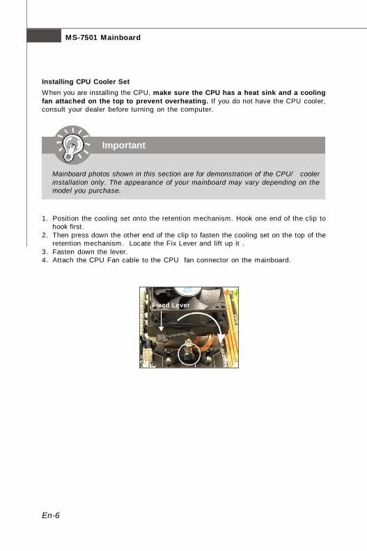
Installing CPU Cooler SetWhen you are installing the CPU, make sure the CPU has a heat sink and a coolingfan attached on the top to prevent overheating. If you do not have the CPU cooler,consult your dealer before turning on the computer.
1. Position the cooling set onto the retention mechanism. Hook one end of the clip tohook first.
2. Then press down the other end of the clip to fasten the cooling set on the top of theretention mechanism. Locate the Fix Lever and lift up it .
3. Fasten down the lever.4. Attach the CPU Fan cable to the CPU fan connector on the mainboard.
Fixed Lever
Important
Mainboard photos shown in this section are for demonstration of the CPU/ coolerinstallation only. The appearance of your mainboard may vary depending on themodel you purchase.
PDF created with pdfFactory Pro trial version www.pdffactory.com

En-7
Engl
ish
Memory
Dual-Channel mode Population RuleIn Dual-Channel mode, the memory modules can transmit and receive data with twodata bus lines simultaneously. Enabling Dual-Channel mode can enhance the systemperformance. Please refer to the following illustrations for population rules under Dual-Channel mode.
These DIMM slots are used for installing memory modules.For more information on compatible components, please visit http://global.msi.com.tw/index.php?func=testreport
DDR2240-pin, 1.8V
64x2=128 pin56x2=112 pin
1 DIMM1 DIMM2
DIMM3
DIMM4
2 DIMM1
DIMM2
DIMM3
DIMM4
3 DIMM1
DIMM2
DIMM3
DIMM4
EmptyInstalled
PDF created with pdfFactory Pro trial version www.pdffactory.com
En-8
MS-7501 Mainboard
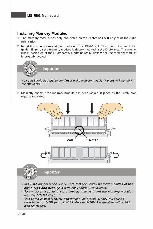
Installing Memory Modules1. The memory module has only one notch on the center and will only fit in the right
orientation.2. Insert the memory module vertically into the DIMM slot. Then push it in until the
golden finger on the memory module is deeply inserted in the DIMM slot. The plasticclip at each side of the DIMM slot will automatically close when the memory moduleis properly seated.
3. Manually check if the memory module has been locked in place by the DIMM slotclips at the sides.
Important
You can barely see the golden finger if the memory module is properly inserted inthe DIMM slot.
Volt Notch
Important
- In Dual-Channel mode, make sure that you install memory modules of thesame type and density in different channel DIMM slots.
- To enable successful system boot-up, always insert the memory modulesinto the DIMM1 first.
- Due to the chipset resource deployment, the system density will only bedetected up to 7+GB (not full 8GB) when each DIMM is installed with a 2GBmemory module.
PDF created with pdfFactory Pro trial version www.pdffactory.com
En-9
Engl
ish
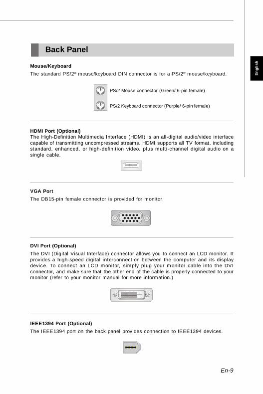
IEEE1394 Port (Optional)The IEEE1394 port on the back panel provides connection to IEEE1394 devices.
Back Panel
Mouse/KeyboardThe standard PS/2® mouse/keyboard DIN connector is for a PS/2® mouse/keyboard.
PS/2 Mouse connector (Green/ 6-pin female)
PS/2 Keyboard connector (Purple/ 6-pin female)
HDMI Port (Optional)The High-Definition Multimedia Interface (HDMI) is an all-digital audio/video interfacecapable of transmitting uncompressed streams. HDMI supports all TV format, includingstandard, enhanced, or high-definition video, plus multi-channel digital audio on asingle cable.
VGA PortThe DB15-pin female connector is provided for monitor.
DVI Port (Optional)The DVI (Digital Visual Interface) connector allows you to connect an LCD monitor. Itprovides a high-speed digital interconnection between the computer and its displaydevice. To connect an LCD monitor, simply plug your monitor cable into the DVIconnector, and make sure that the other end of the cable is properly connected to yourmonitor (refer to your monitor manual for more information.)
PDF created with pdfFactory Pro trial version www.pdffactory.com

En-10
MS-7501 Mainboard
LANThe standard RJ-45 LAN jack is for connection to the Local Area Network (LAN). You canconnect a network cable to it.
LED Color LED State Condition
Off LAN link is not established.
Left Orange On (steady state) LAN link is established.
On (brighter & pulsing) The computer is communicating with another computer on the LAN.
Green Off 10 Mbit/sec data rate is selected.
Right On 100 Mbit/sec data rate is selected.
Orange On 1000 Mbit/sec data rate is selected.
USB PortThe USB (Universal Serial Bus) port is for attaching USB devices such as keyboard,mouse, or other USB-compatible devices.
Audio JacksThese audio connectors are used for audio devices. You can differentiate the color ofthe audio jacks for different audio sound effects.
Line-In (Blue) - Line In, is used for external CD player, tape player or other audiodevices.
Line-Out (Green) - Line Out, is a connector for speakers or headphones.MIC (Pink) - Mic In, is a connector for microphones.RS-Out (Black) - Rear-Surround Out in 4/ 5.1/ 7.1 channel mode.CS-Out (Orange) - Center/ Subwoofer Out in 5.1/ 7.1 channel mode.SS-Out (Gray) - Side-Surround Out 7.1 channel mode.
PDF created with pdfFactory Pro trial version www.pdffactory.com

En-11
Engl
ish
Power Supply AttachmentBefore inserting the power supply connector, always make sure that all components areinstalled properly to ensure that no damage will be caused. All power connectors onthe mainbnoard have to connect to the ATX power supply and have to work together toensure stable operation of the mainboard.
ATX 24-Pin Power ConnectorThis connector allows you to connect an ATX 24-pin power supply. To connect the ATX24-pin power supply, make sure the plug of the power supply is inserted in the properorientation and the pins are aligned. Then push down the power supply firmly into theconnector.You may use the 20-pin ATX power supply as you like. If you’d like to use the 20-pin ATXpower supply, please plug your power supply along with pin 1 & pin 13.
ATX 12V Power ConnectorThis 12V power connector is used to provide power to the CPU.
Connectors, Jumpers, Slots
PWR14
21
3
12VGND
12VGND
1
12 24
13+3.3V+3.3VGND+5V
GND+5V
GNDPWR OK
5VSB+12V+12V
+3.3V GND+5V+5V+5VNCGNDGNDGNDPS-ON#GND-12V+3.3V
ATXPWR1
PDF created with pdfFactory Pro trial version www.pdffactory.com
En-12
MS-7501 Mainboard
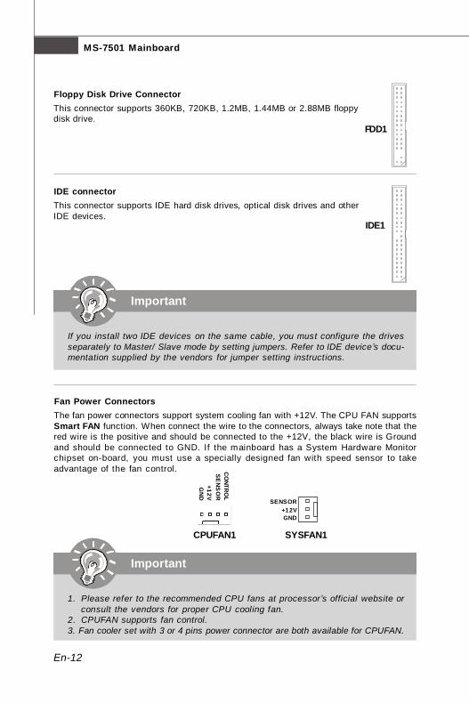
Floppy Disk Drive ConnectorThis connector supports 360KB, 720KB, 1.2MB, 1.44MB or 2.88MB floppydisk drive.
IDE connectorThis connector supports IDE hard disk drives, optical disk drives and otherIDE devices.
Important
If you install two IDE devices on the same cable, you must configure the drivesseparately to Master/ Slave mode by setting jumpers. Refer to IDE device’s docu-mentation supplied by the vendors for jumper setting instructions.
FDD1
Fan Power ConnectorsThe fan power connectors support system cooling fan with +12V. The CPU FAN supportsSmart FAN function. When connect the wire to the connectors, always take note that thered wire is the positive and should be connected to the +12V, the black wire is Groundand should be connected to GND. If the mainboard has a System Hardware Monitorchipset on-board, you must use a specially designed fan with speed sensor to takeadvantage of the fan control.
Important
1. Please refer to the recommended CPU fans at processor’s official website orconsult the vendors for proper CPU cooling fan.
2. CPUFAN supports fan control.3. Fan cooler set with 3 or 4 pins power connector are both available for CPUFAN.
SYSFAN1
SENSOR+12VGND
CPUFAN1
SE
NS
OR
+12VG
ND
CO
NTRO
L
IDE1
PDF created with pdfFactory Pro trial version www.pdffactory.com
En-13
Engl
ish
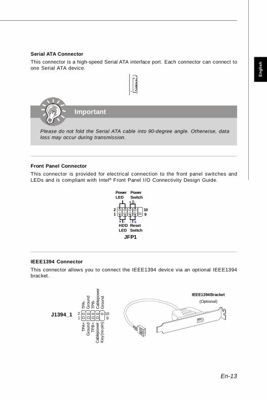
Front Panel ConnectorThis connector is provided for electrical connection to the front panel switches andLEDs and is compliant with Intel® Front Panel I/O Connectivity Design Guide.
IEEE1394 ConnectorThis connector allows you to connect the IEEE1394 device via an optional IEEE1394bracket.
Serial ATA ConnectorThis connector is a high-speed Serial ATA interface port. Each connector can connect toone Serial ATA device.
Important
Please do not fold the Serial ATA cable into 90-degree angle. Otherwise, dataloss may occur during transmission.
IEEE1394 Bracket(Optional)
12
910
HDDLED
ResetSwitch
PowerLED
PowerSwitch
+ +
+
- -
-
JFP1
1 2
9 10
TPA
-G
roun
dTP
B-
Cab
le po
wer
Gro
und
TPA+
Gro
und
TPB
+C
able
pow
erK
ey (n
o pi
n)
J1394_1
PDF created with pdfFactory Pro trial version www.pdffactory.com

En-14
MS-7501 Mainboard
Front USB ConnectorThis connector, compliant with Intel® I/O Connectivity Design Guide, is ideal for con-necting high-speed USB interface peripherals such as USB HDD, digital cameras, MP3players, printers, modems and the like.
Important
Note that the pins of VCC and GND must be connected correctly to avoid possibledamage.
USB 2.0 Bracket(Optional)
Chassis Intrusion ConnectorThis connector connects to the chassis intrusion switch cable. If the chassis is opened,the chassis intrusion mechanism will be activated. The system will record this status andshow a warning message on the screen. To clear the warning, you must enter the BIOSutility and clear the record.
Serial Port ConnectorThis connector is a 16550A high speed communications port that sends/receives 16bytes FIFOs. You can attach a serial device to it.
USB
OC
10 1 2
VC
CU
SB0
-U
SB0+
GN
DK
ey (n
o pi
n)
VC
CU
SB1
-U
SB1+
GN
D
9
JUSB1/2/3
CINTRU GND1
JCI1
1 92
DC
DS
INSO
UT
DTR
Gro
und
DS
RR
TSC
TSR
I
10JCOM1
PDF created with pdfFactory Pro trial version www.pdffactory.com

En-15
Engl
ish
TPM module ConnectorThis connector connects to a TPM (Trusted Platform Module) module (optional). Pleaserefer to the TPM security platform manual for more details and usages.
S/PDIF-Out ConnectorThis connector is used to connect S/PDIF (Sony & Philips Digital Interconnect Format)interface for digital audio transmission.
SPDOUT1
VCC
SPDIF
GND
Front Panel Audio ConnectorThis connector allows you to connect the front panel audio and is compliant with Intel®Front Panel I/O Connectivity Design Guide.
12
910
MIC
_L
MIC
_R
LIN
E o
ut_R
Fron
t_JD
LIN
E o
ut_L
Gro
und
NC
MIC
_JD
NC
(No
pin)
LIN
E o
ut_J
D
JAUD1
CD-In ConnectorThis connector is provided for external audio input.
GND RL
JCD1
21
1413
3Vdual / 3V_STB LCLKLRST#LAD0LAD1LAD2LAD3LFRAME#
VCC3SIRQVCC5
Key(no pin)GNDGND
JTPM1
PDF created with pdfFactory Pro trial version www.pdffactory.com

En-16
MS-7501 Mainboard
Clear CMOS JumperThere is a CMOS RAM onboard that has a power supply from an external battery to keepthe data of system configuration. With the CMOS RAM, the system can automaticallyboot OS every time it is turned on. If you want to clear the system configuration, set thejumper to clear data.
Important
You can clear CMOS by shorting 2-3 pin while the system is off. Then return to 1-2 pin position. Avoid clearing the CMOS while the system is on; it will damagethe mainboard.
Clear Data
1 3
Keep Data
1 3
JBAT11
PDF created with pdfFactory Pro trial version www.pdffactory.com
En-17
Engl
ish
Important
When adding or removing expansion cards, make sure that you unplug the powersupply first. Meanwhile, read the documentation for the expansion card to configureany necessary hardware or software settings for the expansion card, such asjumpers, switches or BIOS configuration.
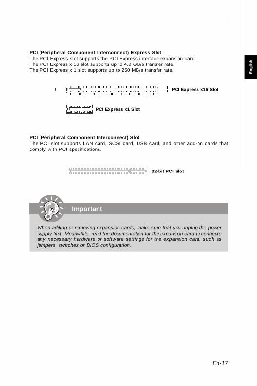
PCI (Peripheral Component Interconnect) Express SlotThe PCI Express slot supports the PCI Express interface expansion card.The PCI Express x 16 slot supports up to 4.0 GB/s transfer rate.The PCI Express x 1 slot supports up to 250 MB/s transfer rate.
PCI (Peripheral Component Interconnect) SlotThe PCI slot supports LAN card, SCSI card, USB card, and other add-on cards thatcomply with PCI specifications.
32-bit PCI Slot
PCI Express x16 Slot
PCI Express x1 Slot
PDF created with pdfFactory Pro trial version www.pdffactory.com

En-18
MS-7501 Mainboard
BIOS Setup
This chapter provides basic information on the BIOS Setup program and allows you toconfigure the system for optimum use. You may need to run the Setup program when:* An error message appears on the screen during the system booting up, and requests
you to run BIOS SETUP.* You want to change the default settings for customized features.
Important
1.The items under each BIOS category described in this chapter are under con-tinuous update for better system performance. Therefore, the description maybe slightly different from the latest BIOS and should be held for reference only.
2.Upon boot-up, the 1st line appearing after the memory count is the BIOSversion. It is usually in the format:
A7501AMS V1.0 062508 where:1st digit refers to BIOS maker as A = AMI, W = AWARD, and P = PHOENIX.2nd - 5th digit refers to the model number.6th refers to the Chipset vender as A = ATi, I = Intel, V = VIA, N = Nvidia, U = ULi.7th - 8th digit refers to the customer as MS = all standard customers.V1.0 refers to the BIOS version.062508 refers to the date this BIOS was released.
PDF created with pdfFactory Pro trial version www.pdffactory.com

En-19
Engl
ish
Entering SetupPower on the computer and the system will start POST (Power On Self Test) process.When the message below appears on the screen, press <DEL> key to enter Setup.
Press DEL to enter SETUPIf the message disappears before you respond and you still wish to enter Setup, restartthe system by turning it OFF and On or pressing the RESET button. You may also restartthe system by simultaneously pressing <Ctrl>, <Alt>, and <Delete> keys.
Getting HelpAfter entering the Setup menu, the first menu you will see is the Main Menu.
Main MenuThe main menu lists the setup functions you can make changes to. You can use thearrow keys (↑↓ ) to select the item. The on-line description of the highlighted setupfunction is displayed at the bottom of the screen.
Sub-MenuIf you find a right pointer symbol (as shown in the right view)appears to the left of certain fields that means a sub-menucontaining additional options can be launched from this field.You can use control keys (↑↓ ) to highlight the field andpress <Enter> to call up the sub-menu. Then you can use the control keys to enter valuesand move from field to field within a sub-menu. If you want to return to the main menu,just press <Esc >.
General Help <F1>The BIOS setup program provides a General Help screen. You can call up this screenfrom any menu by simply pressing <F1>. The Help screen lists the appropriate keys touse and the possible selections for the highlighted item. Press <Esc> to exit the Helpscreen.
PDF created with pdfFactory Pro trial version www.pdffactory.com
En-20
MS-7501 Mainboard
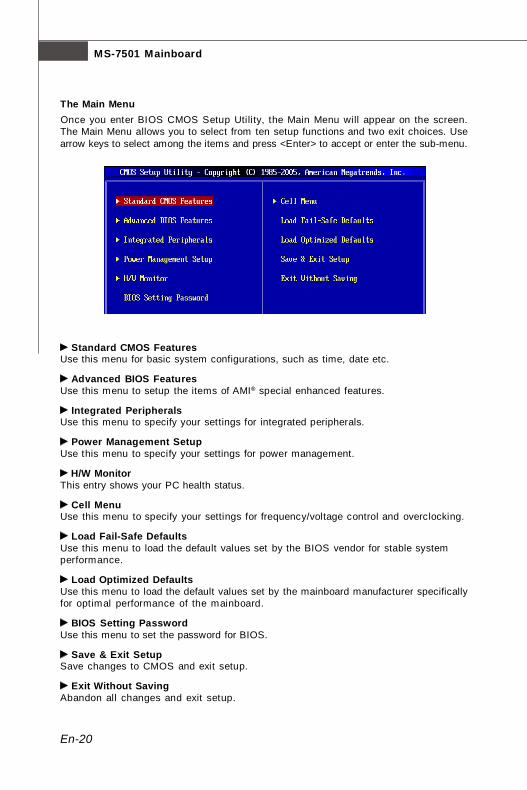
The Main MenuOnce you enter BIOS CMOS Setup Utility, the Main Menu will appear on the screen.The Main Menu allows you to select from ten setup functions and two exit choices. Usearrow keys to select among the items and press <Enter> to accept or enter the sub-menu.
Standard CMOS FeaturesUse this menu for basic system configurations, such as time, date etc.
Advanced BIOS FeaturesUse this menu to setup the items of AMI® special enhanced features.
Integrated PeripheralsUse this menu to specify your settings for integrated peripherals.
Power Management SetupUse this menu to specify your settings for power management.
H/W MonitorThis entry shows your PC health status.
Cell MenuUse this menu to specify your settings for frequency/voltage control and overclocking.
Load Fail-Safe DefaultsUse this menu to load the default values set by the BIOS vendor for stable systemperformance.
Load Optimized DefaultsUse this menu to load the default values set by the mainboard manufacturer specificallyfor optimal performance of the mainboard.
BIOS Setting PasswordUse this menu to set the password for BIOS.
Save & Exit SetupSave changes to CMOS and exit setup.
Exit Without SavingAbandon all changes and exit setup.
PDF created with pdfFactory Pro trial version www.pdffactory.com
En-21
Engl
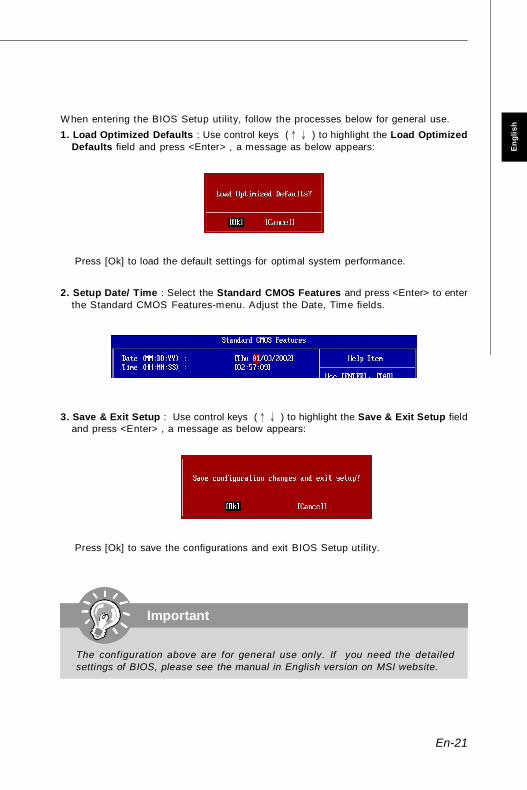
ishWhen entering the BIOS Setup utility, follow the processes below for general use.
1. Load Optimized Defaults : Use control keys (↑↓ ) to highlight the Load OptimizedDefaults field and press <Enter> , a message as below appears:
Press [Ok] to load the default settings for optimal system performance.
2. Setup Date/ Time : Select the Standard CMOS Features and press <Enter> to enterthe Standard CMOS Features-menu. Adjust the Date, Time fields.
3. Save & Exit Setup : Use control keys (↑↓ ) to highlight the Save & Exit Setup fieldand press <Enter> , a message as below appears:
Press [Ok] to save the configurations and exit BIOS Setup utility.
Important
The configuration above are for general use only. If you need the detailedsettings of BIOS, please see the manual in English version on MSI website.
PDF created with pdfFactory Pro trial version www.pdffactory.com

En-22
MS-7501 Mainboard
Software Information
Take out the Driver/Utility CD included in the mainboard package and place it into theCD-ROM drive. The installation will auto-run. Simply click the driver or utiltiy and followthe pop-up screens to complete the installation. The Driver/Utility CD contains the:Driver menu - The Driver menu shows the available drivers. Install the driver at your desire to activate your hardware device.Utility menu - The Utility menu shows the software applications supported by the
mainboard.WebSite menu - The WebSite menu shows the websites for detailed information.
Important
Please visit the MSI website to get the latest drivers and BIOS for better systemperformance.
PDF created with pdfFactory Pro trial version www.pdffactory.com

De-1
Deu
tsch
K9A2GM / K9A2VMBenutzerhandbuch
Deutsch
PDF created with pdfFactory Pro trial version www.pdffactory.com

De-2
MS-7501 Mainboard
Spezifikationen
Prozessoren- Unterstützt AMD Phenom / Athlon 64 / Sempron Prozessoren- Unterstützt Lüftersteuerung über eine 4-polige Stift leiste- Unterstützt bis zu 5000+ und höhere(Weitere CPU Informationen finden Sie unterhttp://global.msi.com.tw/index.php?func=cpuform)
HT (Hyper Transport)- Hyper Transport der Geschwindigkeit unterstützt 2.6GHz
Chipsatz- North-Bridge: AMD 780G / 780V- South-Bridge: AMD SB700
Speicher- DDR2 533/667/800/1066 SDRAM (240-Pin / 1.8V)- 4 DDR2 DIMM Slots (max. 8GB)(Weitere Informationen zu kompatiblen Speichermodulen finden Sieunter http://global.msi.com.tw/index.php?func=testreport)
LAN- Gigabit Fast Ethernet über Realtek RTL8111C
IEEE 1394 (Optional)- Chip integrated by JMicron 381- Unterstützt Datenübertragungsraten von bis zu 400Mb/s
Audio- Onboard Chip über Realtek ALC888- Flexible 8-Kanal-Audio mit “Jack Sensing”- Konform mit Azalia 1.0 Spec
IDE- 1 IDE Port über SB700- Unterstützt die Betrieb mit Ultra DMA133/100/66- Unterstützt die Betrieb mit PIO, Bus Mastering
SATA- 4 SATA II-Ports mit SB700- Unterstützt 4 SATA II-Geräte- Unterstützt Datenübertragungsraten von bis zu 3Gb/s
PDF created with pdfFactory Pro trial version www.pdffactory.com

De-3
Deu
tsch
Diskette- 1 Disketten Anschluss- Unterstützt 1 FDD with 360KB, 720KB, 1.2MB, 1.44MB und 2.88MB
Anschlüsse
Hintere Ein-/ und Ausgänge- 1 PS/2 Mausanschluss- 1 PS/2 Tastaturanschluss- 1 IEEE 1394 Anschluss (Optional)- 4 USB 2.0 Anschlüsse- 1 Gigabit LAN Anschluss- 1 VGA Anschluss- 1 DVI Anschluss (Optional)- 1 HDMI Anschluss (Optional)- 6 Audiobuchsen
On-Board Stiftleiste/ Anschlüsse- 3 USB 2.0 Stiftleisten- 1 1394 Stiftleiste (optional)- 1 TPM Schnittstelle (optional)- 1 Serielle Schnittstelle- 1 CD-Stiftleiste für Audio Eingang- 1 SPDIF-Ausgang Stiftleiste- 1 Gehäusekontaktschalter- 1 Fronttafel-Audioanschluss
Schnittstellen- 1 PCI Express x16 Schnittstelle- 1 PCI Express x1 Schnittstelle- 2 32-Bit/33MHz PCI Schnittstellen
Form Faktor- M-ATX (24.4cm X 24.4 cm)
Montage- 6 Montagebohrungen
PDF created with pdfFactory Pro trial version www.pdffactory.com

De-4
MS-7501 Mainboard
DIMM Slots, S. De-7
CPUFAN1, S. De-12CPU, S. De-5PWR1, S. De-11
ATXPWR1,S. De-11
IDE1,S. De-12
SATA1~4,S. De-13
PCI ExpressSlots,S. De-17
JBAT1,S. De-16
JTPM1,S. De-15
JCI1, S. De-14
SYSFAN1,S. De-12
PCI Slots,S. De-17
JUSB1~3,S. De-14
F D D 1 ,S. De-12
JFP1, S. De-13
J1394_1, S. De-13JCD1, S. De-15
JAUD1, S. De-15
SPDOUT1, S. De-15
JCOM1,S. De-14
K9A2GM / K9A2VM (MS-7501 v1.X)Micro-ATX Mainboard
Maus, S. De-9
Ta sta tu r,S. De-9
HDMI(Optional),
S. De-9
DVI-D(Optional),
S. De-9
VGA, S. De-9
IEEE 1394(Optional),
S. De-9LAN, S. De-10
USB Ports, S. De-10 Audio Jacks,S. De-10
PDF created with pdfFactory Pro trial version www.pdffactory.com
De-5
Deu
tsch
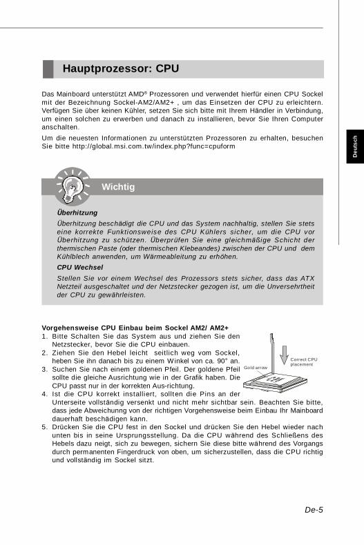
Das Mainboard unterstützt AMD® Prozessoren und verwendet hierfür einen CPU Sockelmit der Bezeichnung Sockel-AM2/AM2+ , um das Einsetzen der CPU zu erleichtern.Verfügen Sie über keinen Kühler, setzen Sie sich bitte mit Ihrem Händler in Verbindung,um einen solchen zu erwerben und danach zu installieren, bevor Sie Ihren Computeranschalten.Um die neuesten Informationen zu unterstützten Prozessoren zu erhalten, besuchenSie bitte http://global.msi.com.tw/index.php?func=cpuform
Hauptprozessor: CPU
Vorgehensweise CPU Einbau beim Sockel AM2/ AM2+1. Bitte Schalten Sie das System aus und ziehen Sie den
Netzstecker, bevor Sie die CPU einbauen.2. Ziehen Sie den Hebel leicht seitlich weg vom Sockel,
heben Sie ihn danach bis zu einem Winkel von ca. 90° an.3. Suchen Sie nach einem goldenen Pfeil. Der goldene Pfeil
sollte die gleiche Ausrichtung wie in der Grafik haben. DieCPU passt nur in der korrekten Aus-richtung.
4. Ist die CPU korrekt installiert, sollten die Pins an derUnterseite vollständig versenkt und nicht mehr sichtbar sein. Beachten Sie bitte,dass jede Abweichunng von der richtigen Vorgehensweise beim Einbau Ihr Mainboarddauerhaft beschädigen kann.
5. Drücken Sie die CPU fest in den Sockel und drücken Sie den Hebel wieder nachunten bis in seine Ursprungsstellung. Da die CPU während des Schließens desHebels dazu neigt, sich zu bewegen, sichern Sie diese bitte während des Vorgangsdurch permanenten Fingerdruck von oben, um sicherzustellen, dass die CPU richtigund vollständig im Sockel sitzt.
Gold arrow
Correct CPUplacement
Wichtig
ÜberhitzungÜberhitzung beschädigt die CPU und das System nachhaltig, stellen Sie stetseine korrekte Funktionsweise des CPU Kühlers sicher, um die CPU vorÜberhitzung zu schü tzen. Überprüfen Sie eine gleichmäßige Schicht derthermischen Paste (oder thermischen Klebeandes) zwischen der CPU und demKühlblech anwenden, um Wärmeableitung zu erhöhen.CPU WechselStellen Sie vor einem Wechsel des Prozessors stets sicher, dass das ATXNetzteil ausgeschaltet und der Netzstecker gezogen ist, um die Unversehrtheitder CPU zu gewährleisten.
PDF created with pdfFactory Pro trial version www.pdffactory.com
De-6
MS-7501 Mainboard
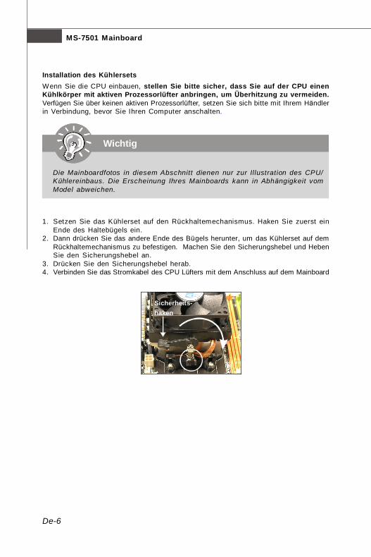
Installation des KühlersetsWenn Sie die CPU einbauen, stellen Sie bitte sicher, dass Sie auf der CPU einenKühlkörper mit aktiven Prozessorlüfter anbringen, um Überhitzung zu vermeiden.Verfügen Sie über keinen aktiven Prozessorlüfter, setzen Sie sich bitte mit Ihrem Händlerin Verbindung, bevor Sie Ihren Computer anschalten.
1. Setzen Sie das Kühlerset auf den Rückhaltemechanismus. Haken Sie zuerst einEnde des Haltebügels ein.
2. Dann drücken Sie das andere Ende des Bügels herunter, um das Kühlerset auf demRückhaltemechanismus zu befestigen. Machen Sie den Sicherungshebel und HebenSie den Sicherungshebel an.
3. Drücken Sie den Sicherungshebel herab.4. Verbinden Sie das Stromkabel des CPU Lüfters mit dem Anschluss auf dem Mainboard
Wichtig
Die Mainboardfotos in diesem Abschnitt dienen nur zur Illustration des CPU/Kühlereinbaus. Die Erscheinung Ihres Mainboards kann in Abhängigkeit vomModel abweichen.
Sicherheits-haken
PDF created with pdfFactory Pro trial version www.pdffactory.com

De-7
Deu
tsch
EmptyInstalled
Diese DIMM-Steckplätze nehmen Arbeitsspeichermodule auf.Die neusten Informationen über kompatible Bauteile finden Sie unter http://global.msi.com.tw/index.php?func=testreport.
1 DIMM1 DIMM2 DIMM3
DIMM4
2 DIMM1
DIMM2 DIMM3
DIMM4
3 DIMM1
DIMM2 DIMM3
DIMM4
Populationsregeln für Dual-Channel-SpeicherIm Dual-Channel-Modus können Arbeitsspeichermodule Daten über zweiDatenbusleitungen gleichzeitig senden und empfangen. Durch Aktivierung des Dual-Channel-Modus wird die Leistung Ihres Systems verbessert. Bitte beachten Sie diefolgenden Abbildungen zur Veranschaulichung der Populationsregeln im Dual-Channel-Modus.
DDR2240-polig, 1,8V
64x2=128 Pole56x2=112 Pole
Arbeitsspeicher
PDF created with pdfFactory Pro trial version www.pdffactory.com

De-8
MS-7501 Mainboard
Volt Notch
Installieren der Arbeitsspeichermodule1. Das Arbeitsspeichermodul hat nur eine Kerbe in der Mitte und passt nur in eine
Richtung in den Steckplatz.2. Stecken Sie das Arbeitsspeichermodul senkrecht in den DIMM-Steckplatz ein. Drücken
Sie anschließend das Arbeitsspeichermodul nach unten, bis die Kontaktseite richtigtief in dem DIMM-Steckplatz sitzt. Der Kunststoffbügel an jedem Ende des DIMM-Steckplatzes schnappt automatisch ein, wenn das Arbeitsspeichermodul richtigeingesetzt ist.
3. Prüfen Sie von Hand, ob das Arbeitsspeichermodul von den seitlichen Bügeln amDIMM-Steckplatz richtig gehalten wird.
Wichtig
- Achten Sie im Dual-Channel-Modus darauf, dass die Arbeitsspeichermodulein d en ver sc hie den en DIMM -St eck plä tz en in Ty p und Di ch teübereinstimmen.
- Fangen Sie bei der Speichermodulinstallation immer mit dem SteckplatzDIMM1 an. Andernfalls kann das System nicht gestartet werden.
- Aufgrund der Chipsatzressourcennutzung wird nur eine Systemdichte bis7+GB (nicht volle 8 GB) erkannt, wenn jeder DIMM mit einem 2GB-Arbeitsspeichermodul besetzt wird.
Wichtig
Die goldenen Kontakte sind kaum zu sehen, wenn das Arbeitsspeichermodulrichtig im DIMM-Steckplatz sitzt.
PDF created with pdfFactory Pro trial version www.pdffactory.com
De-9
Deu
tsch
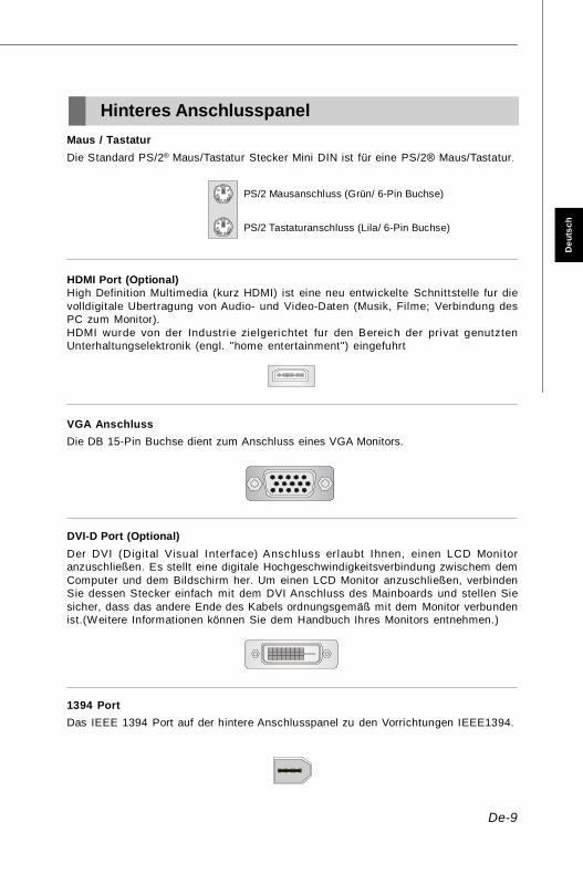
HDMI Port (Optional)High Definition Multimedia (kurz HDMI) ist eine neu entwickelte Schnittstelle fur dievolldigitale Ubertragung von Audio- und Video-Daten (Musik, Filme; Verbindung desPC zum Monitor).HDMI wurde von der Industrie zielgerichtet fur den Bereich der privat genutztenUnterhaltungselektronik (engl. "home entertainment") eingefuhrt
VGA AnschlussDie DB 15-Pin Buchse dient zum Anschluss eines VGA Monitors.
Hinteres AnschlusspanelMaus / TastaturDie Standard PS/2® Maus/Tastatur Stecker Mini DIN ist für eine PS/2® Maus/Tastatur.
PS/2 Mausanschluss (Grün/ 6-Pin Buchse)
PS/2 Tastaturanschluss (Lila/ 6-Pin Buchse)
DVI-D Port (Optional)Der DVI (Digital Visual Interface) Anschluss erlaubt Ihnen, einen LCD Monitoranzuschließen. Es stellt eine digitale Hochgeschwindigkeitsverbindung zwischem demComputer und dem Bildschirm her. Um einen LCD Monitor anzuschließen, verbindenSie dessen Stecker einfach mit dem DVI Anschluss des Mainboards und stellen Siesicher, dass das andere Ende des Kabels ordnungsgemäß mit dem Monitor verbundenist.(Weitere Informationen können Sie dem Handbuch Ihres Monitors entnehmen.)
1394 PortDas IEEE 1394 Port auf der hintere Anschlusspanel zu den Vorrichtungen IEEE1394.
PDF created with pdfFactory Pro trial version www.pdffactory.com
De-10
MS-7501 Mainboard
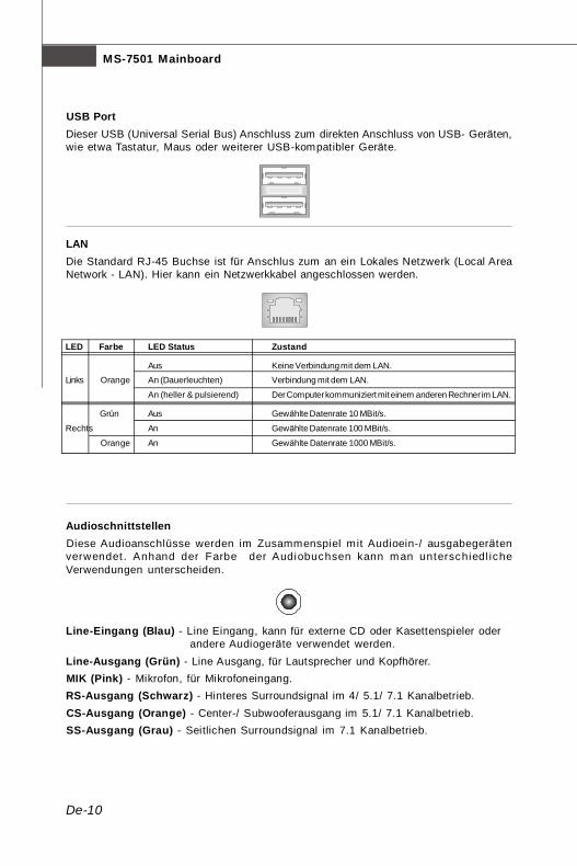
USB PortDieser USB (Universal Serial Bus) Anschluss zum direkten Anschluss von USB- Geräten,wie etwa Tastatur, Maus oder weiterer USB-kompatibler Geräte.
LANDie Standard RJ-45 Buchse ist für Anschlus zum an ein Lokales Netzwerk (Local AreaNetwork - LAN). Hier kann ein Netzwerkkabel angeschlossen werden.
LED Farbe LED Status Zustand
Aus Keine Verbindung mit dem LAN.Links Orange An (Dauerleuchten) Verbindung mit dem LAN.
An (heller & pulsierend) Der Computer kommuniziert mit einem anderen Rechner im LAN.
Grün Aus Gewählte Datenrate 10 MBit/s.
Rechts An Gewählte Datenrate 100 MBit/s.
Orange An Gewählte Datenrate 1000 MBit/s.
AudioschnittstellenDiese Audioanschlüsse werden im Zusammenspiel mit Audioein-/ ausgabegerätenverwendet . Anhand der Farbe der Audiobuchsen kann man unterschiedl icheVerwendungen unterscheiden.
Line-Eingang (Blau) - Line Eingang, kann für externe CD oder Kasettenspieler oderandere Audiogeräte verwendet werden.
Line-Ausgang (Grün) - Line Ausgang, für Lautsprecher und Kopfhörer.MIK (Pink) - Mikrofon, für Mikrofoneingang.RS-Ausgang (Schwarz) - Hinteres Surroundsignal im 4/ 5.1/ 7.1 Kanalbetrieb.CS-Ausgang (Orange) - Center-/ Subwooferausgang im 5.1/ 7.1 Kanalbetrieb.SS-Ausgang (Grau) - Seitlichen Surroundsignal im 7.1 Kanalbetrieb.
PDF created with pdfFactory Pro trial version www.pdffactory.com
De-11
Deu
tsch
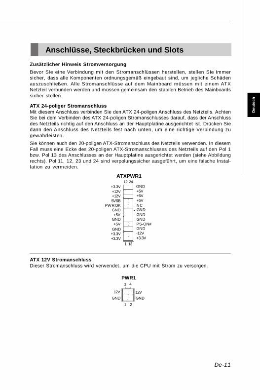
ATX 24-poliger StromanschlussMit diesem Anschluss verbinden Sie den ATX 24-poligen Anschluss des Netzteils. AchtenSie bei dem Verbinden des ATX 24-poligen Stromanschlusses darauf, dass der Anschlussdes Netzteils richtig auf den Anschluss an der Hauptplatine ausgerichtet ist. Drücken Siedann den Anschluss des Netzteils fest nach unten, um eine richtige Verbindung zugewährleisten.Sie können auch den 20-poligen ATX-Stromanschluss des Netzteils verwenden. In diesemFall muss eine Ecke des 20-poligen ATX-Stromanschlusses des Netzteils auf den Pol 1bzw. Pol 13 des Anschlusses an der Hauptplatine ausgerichtet werden (siehe Abbildungrechts). Pol 11, 12, 23 und 24 sind verpolungssicher ausgeführt, um eine falsche Instal-lation zu vermeiden.
ATX 12V StromanschlussDieser Stromanschluss wird verwendet, um die CPU mit Strom zu versorgen.
Anschlüsse, Steckbrücken und Slots
PWR14
21
3
12VGND
12VGND
1
12 24
13+3.3V+3.3VGND+5V
GND+5V
GNDPWR OK
5VSB+12V+12V
+3.3V GND+5V+5V+5VNCGNDGNDGNDPS-ON#GND-12V+3.3V
ATXPWR1
Zusätzlicher Hinweis StromversorgungBevor Sie eine Verbindung mit den Stromanschlüssen herstellen, stellen Sie immersicher, dass alle Komponenten ordnungsgemäß eingebaut sind, um jegliche Schädenauszuschließen. Alle Stromanschlüsse auf dem Mainboard müssen mit einem ATXNetzteil verbunden werden und müssen gemeinsam den stabilen Betrieb des Mainboardssicher stellen.
PDF created with pdfFactory Pro trial version www.pdffactory.com

De-12
MS-7501 Mainboard
Anschluss des DiskettenlaufwerksDiese Anschluss unterstützt ein Diskettenlaufwerke mit 360KB, 720KB, 1.2MB, 1.44MB oder 2.88MB Kapazität.
IDE AnschlussAn diesen Anschluss können IDE Festplatten, optische Laufwerke (CD/DVD-Brenner, ...) und andere Geräte betrieben werden.
FDD1
Wichtig
Verbinden Sie zwei Laufwerke über ein Kabel, müssen Sie das zweite Laufwerkim Slave-Modus konfigurieren, indem Sie entsprechend den Jumper setzen.Entnehmen Sie bitte die Anweisungen zum Setzen des Jumpers der Dokumentationder IDE Geräte, die der Festplattenhersteller zur Verfügung stellt.
Stromanschlüsse für LüfterDie Anschlüsseunterstützen aktive Systemlüfter mit + 12V. CPU FAN kann Smart FANFunktion unterstützen. Wenn Sie den Anschluss herstellen, sollten Sie immer daraufachten, dass der rote Draht der positive Pol ist, und mit +12V verbunden werden sollte,der schwarze Draht ist der Erdkontakt und sollte mit GND verbunden werden. Ist IhrMainboard mit einem Chipsatz zur Überwachung der Systemhardware versehen, dannbrauchen Sie einen speziellen Lüfter mit Tacho, um die Vorteile der Steuerung desCPU Lüfters zu nutzen.
SYSFAN1
SENSOR+12VGND
CPUFAN1
SE
NS
OR
+12VG
ND
CO
NTRO
L
Wichtig
1. Bitte informieren Sie sich auf der offiziellen Website vom Prozessor überempfohlene CPU Kühler oder fragen Sie Ihren Händler nach einem geeignetenLüfter.
2. CPUFAN unterstützt die Lüfterkontrolle.3. CPUFAN kann die Lüfter mit drei- und vierpolige Stecker unterstützen.
IDE1
PDF created with pdfFactory Pro trial version www.pdffactory.com
De-13
Deu
tsch
12
910
HDDLED
ResetSwitch
PowerLED
PowerSwitch
+ +
+
- -
-
JFP1
1 2
9 10
TPA
-G
roun
dTP
B-
Cab
le po
wer
Gro
und
TPA+
Gro
und
TPB
+C
able
pow
erK
ey (n
o pi
n)
J1394_1
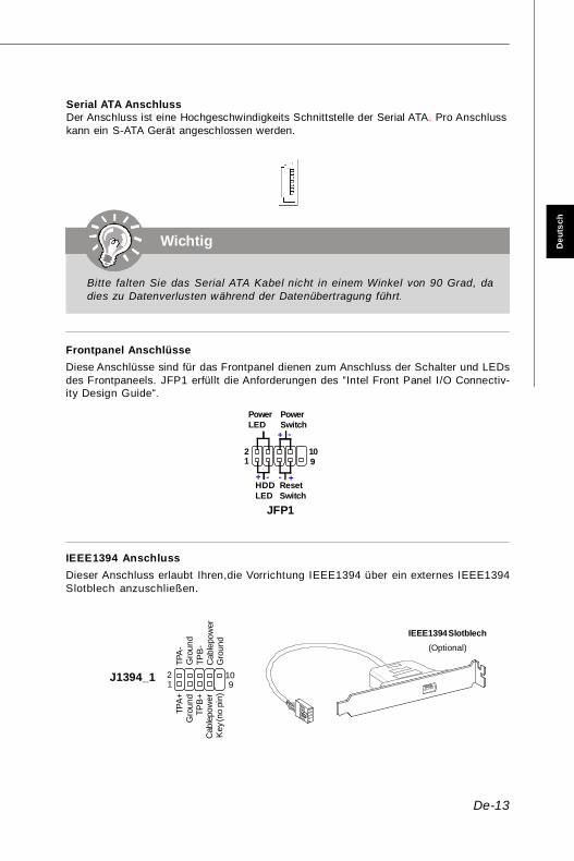
Serial ATA AnschlussDer Anschluss ist eine Hochgeschwindigkeits Schnittstelle der Serial ATA. Pro Anschlusskann ein S-ATA Gerät angeschlossen werden.
Wichtig
Bitte falten Sie das Serial ATA Kabel nicht in einem Winkel von 90 Grad, dadies zu Datenverlusten während der Datenübertragung führt.
Frontpanel AnschlüsseDiese Anschlüsse sind für das Frontpanel dienen zum Anschluss der Schalter und LEDsdes Frontpaneels. JFP1 erfüllt die Anforderungen des “Intel Front Panel I/O Connectiv-ity Design Guide“.
IEEE1394 AnschlussDieser Anschluss erlaubt Ihren,die Vorrichtung IEEE1394 über ein externes IEEE1394Slotblech anzuschließen.
IEEE1394 Slotblech(Optional)
PDF created with pdfFactory Pro trial version www.pdffactory.com
De-14
MS-7501 Mainboard
USB
OC
10 1 2
VC
CU
SB0
-U
SB0+
GN
DK
ey (n
o pi
n)
VC
CU
SB1
-U
SB1+
GN
D
9
JUSB1/2/3
CINTRU GND1
JCI1
1 92
DC
DS
INSO
UT
DTR
Gro
und
DS
RR
TSC
TSR
I
10JCOM1
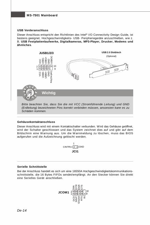
USB VorderanschlussDieser Anschluss entspricht den Richtlinien des Intel® I/O Connectivity Design Guide, istbestens geeignet, Hochgeschwindigkeits- USB- Peripheriegeräte anzuschließen, wie z.B. USB Festplattenlaufwerke, Digitalkameras, MP3-Player, Drucker, Modems undähnliches.
USB 2.0 Slotblech(Optional)
Wichtig
Bitte beachten Sie, dass Sie die mit VCC (Stromführende Leitung) und GND(Erdleitung) bezeichneten Pins korrekt verbinden müssen, ansonsten kann es zuSchäden kommen.
GehäusekontaktanschlussDieser Anschluss wird mit einem Kontaktschalter verbunden. Wird das Gehäuse geöffnet,wird der Schalter geschlossen und das System zeichnet dies auf und gibt auf demBildschirm eine W arnung aus. Um die W arnmeldung zu löschen, muss das BIOSaufgerufen und die Aufzeichnung gelöscht werden.
Serielle SchnittstelleBei der Anschluss handelt es sich um eine 16550A Hochgeschwindigkeitskommunikations-schnittstelle, die 16 Bytes FIFOs sendet/empfängt. An den Stecker können Sie direkteine Serielles Gerät anschließen.
PDF created with pdfFactory Pro trial version www.pdffactory.com
De-15
Deu
tsch
SPDOUT1
VCC
SPDIF
GND
12
910
MIC
_L
MIC
_R
LIN
E o
ut_R
Fron
t_JD
LIN
E o
ut_L
Gro
und
NC
MIC
_JD
NC
(No
pin)
LIN
E o
ut_J
D
JAUD1
GND RL
JCD1
21
1413
3Vdual / 3V_STB LCLKLRST#LAD0LAD1LAD2LAD3LFRAME#
VCC3SIRQVCC5
Key(no pin)GNDGND
JTPM1
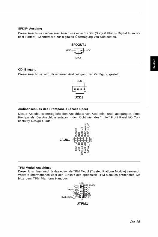
CD- EingangDieser Anschluss wird für externen Audioeingang zur Verfügung gestellt.
SPDIF- AusgangDieser Anschluss dienen zum Anschluss einer SPDIF (Sony & Philips Digital Intercon-nect Format) Schnittstelle zur digitalen Übertragung von Audiodaten.
Audioanschluss des Frontpanels (Azalia Spec)Dieser Anschluss ermöglicht den Anschluss von Audioein- und -ausgängen einesFrontpanels. Der Anschluss entspricht den Richtlinien des “ Intel® Front Panel I/O Con-nectivity Design Guide”.
TPM Modul AnschlussDieser Anschluss wird für das optionale TPM Modul (Trusted Platform Module) verwendt.Weitere Informationen über den Einsatz des optionalen TPM Modules entnehmen Siebitte dem TPM Plattform Handbuch.
PDF created with pdfFactory Pro trial version www.pdffactory.com

De-16
MS-7501 Mainboard
Clear Data
1 3
Keep Data
1 3
JBAT11
Steckbrücke zur CMOS- LöschungAuf dem Mainboard gibt es einen sogenannten CMOS Speicher (RAM), der über eineBatterie gespeist wird und die Daten der Systemkonfiguration enthält. Er ermöglicht esdem Betriebssystem, mit jedem Einschalten automatisch hochzufahren. Wollen Sie dieSystemkonfiguration löschen, verwenden Sie hierfür JBAT1 (Clear CMOS Jumper -Steckbrücke zur CMOS Löschung)..
Wichtig
Sie können den CMOS löschen, indem Sie die Pins 2-3 verbinden, während dasSystem ausgeschaltet ist. Kehren Sie danach zur Pinposition 1-2 zurück. LöschenSie den CMOS nicht, solange das System angeschaltet ist, dies würde dasMainboard beschädigen.
PDF created with pdfFactory Pro trial version www.pdffactory.com

De-17
Deu
tsch
PCI (Peripheral Component Interconnect) Express SlotDer PCI Express Slot unterstutzt die PCI Express Schnittstelle Erweiterungskarten.Der PCI Express x 16 Slot unterstützt die Datenubertragunsraten von bis zu 4.0 GB/s.Der PCI Express x 1 Slot unterstützt die Datenubertragunsraten von bis zu 250 MB/s.
PCI (Peripheral Component Interconnect) SlotDie PCI Steckplätze unterstü tzt LAN Karte, SCSI Karte, USB Karte und andereZusatzkarten cards,die mit PCI Spezifikationen übereinstimmen.
32-bit PCI Slot
PCI Express x16 Slot
PCI Express x1 Slot
Wichtig
Stellen Sie vor dem Einsetzen oder Entnehmen von Karten sicher, dass Sie denNetzs t ec ker gezogen haben. S t ud ie ren Sie b i t t e d ie A n lei t ung zurErweiterungskarte, um jede notwendige Hard - oder Softwareeinstellung für dieErweiterungskarte vorzunehmen, sei es an Steckbrücken (“Jumpern”), Schalternoder im BIOS.
PDF created with pdfFactory Pro trial version www.pdffactory.com

De-18
MS-7501 Mainboard
BIOS Setup
Dieses Kapitel enthält Informationen über das BIOS Setup und ermöglicht es Ihnen, IhrSystem optimal auf Ihre Anforderungen einzustellen. Notwendigkeit zum Aufruf desBIOS besteht, wenn:* Während des Bootvorgangs des Systems eine Fehlermeldung erscheint und Sie zum
Aufruf des BIOS SETUP aufgefordert werden.* Sie die Werkseinstellungen zugunsten individueller Einstellungen ändern wollen.
Wichtig
1.Die Menüpunkte jeder BIOS Kategorie, die in diesem Kapitel beschrieben wird,werden permanent auf den neuesten Stand gebracht, um die Systemleistungzu verbessern. Aus diesem Grunde kann die Beschreibung geringfügig vonder aktuellsten Version des BIOS abweichen und sollte dementsprechendlediglich als Anhaltspunkt dienen.
2. Während des Hochfahrens, wird die BIOS Version in der ersten Zeile nach demHochzählen des Speichers angezeigt, üblicherweise im Format dieses Beispiels:
A7501AMS V1.0 062508 wobei:Die erste Stellen den BIOS-Hersteller bezeichnet, dabei gilt A = AMI, W = AWARD,and P = PHOENIX.2te - 5te Stelle bezeichnet die Modelnummer.6te Stelle bezeichnet den Chipsatzhersteller, A = AMD, I = Intel, V = VIA, N =Nvidia, U = ULi.7te - 8te Stelle bezieht sich auf den Kunden, MS=alle Standardkunden.V1.0 bezieht sich auf die BIOS Version.062508 bezeichnet das Datum der Veröffentlichung des BIOS.
PDF created with pdfFactory Pro trial version www.pdffactory.com

De-19
Deu
tsch
Aufruf des BIOS SetupsNach dem Einschalten beginnt der Computer den POST (Power On Self Test -Selbstüberprüfung nach Anschalten). Sobald die Meldung unten erscheint, drücken Siedie Taste <Entf>(<Del>) um das Setup aufzurufen.
Press DEL to enter SETUPWenn die Nachricht verschwindet, bevor Sie reagieren und Sie möchten immer nochins Setup, starten Sie das System neu, indem Sie es erst AUS- und danach wiederANSCHALTEN, oder die “RESET”-Taste am Gehäuse betät igen. Sie können das Sys-tem außerdem neu starten, indem Sie gleichzeitig die Tasten <Strg>,<Alt> und <Entf>drücken (bei manchen Tastaturen <Ctrl>,<Alt> und <Del>).
Hilfe findenNach dem Start des Setup Menüs erscheint zuerst das Hauptmenü.
HauptmenüDas Hauptmenü l istet Funkt ionen auf, die Sie ändern können. Sie können dieSteuertasten (↑↓ ) verwenden, um einen Menüpunkt auszuwählen. Die Online-Beschreibung des hervorgehobenen Menüpunktes erscheint am unteren Bildschirmrand.
UntermenüsW enn Sie an der linken Sei te best immter Felder einDreieckssymbolf finden (wie rechts dargestellt), bedeuteddies, dass Sie über das entsprechende Feld ein Untermenümit zusätzl ichen Optionen aufrufen können. Durch dieSteuertasten (↑↓ )önnen Sie ein Feld hervorheben und durch Drücken der Eingabetaste<Enter> in das Untermenü gelangen. Dort können Sie mit den Steuertasten W erteeingeben und navigieren. Durch Drücken von <Esc > kommen Sie zurück ins Hauptmenü.
Allgemeine Hilfe <F1>Das BIOS Setup verfügt über eine Allgemeine Hilfe (General Help). Sie können dieseaus jedem Menü einfach durch Drücken der Taste <F1> aufrufen. Sie listet die Tastenund Einstellungen zu dem hervorgehobenen Menüpunkt auf. Um die Hilfe zu verlassen,drücken Sie <Esc>.
PDF created with pdfFactory Pro trial version www.pdffactory.com
De-20
MS-7501 Mainboard
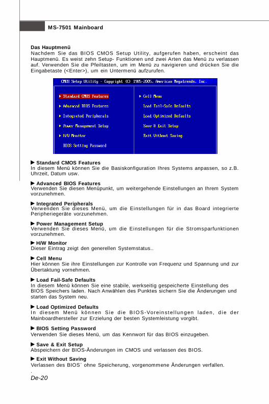
Standard CMOS FeaturesIn diesem Menü können Sie die Basiskonfiguration Ihres Systems anpassen, so z.B.Uhrzeit, Datum usw.
Advanced BIOS FeaturesVerwenden Sie diesen Menüpunkt, um weitergehende Einstellungen an Ihrem Systemvorzunehmen.
Integrated PeripheralsVerwenden Sie dieses Menü, um die Einstellungen für in das Board integriertePeripheriegeräte vorzunehmen.
Power Management SetupVerwenden Sie dieses Menü , um die Einstellungen für die Stromsparfunkt ionenvorzunehmen.
H/W MonitorDieser Eintrag zeigt den generellen Systemstatus..
Cell MenuHier können Sie ihre Einstellungen zur Kontrolle von Frequenz und Spannung und zurÜbertaktung vornehmen.
Load Fail-Safe DefaultsIn diesem Menü können Sie eine stabile, werkseitig gespeicherte Einstellung desBIOS Speichers laden. Nach Anwählen des Punktes sichern Sie die Änderungen undstarten das System neu.
Load Optimized DefaultsI n d iesem Menü kön nen S ie d ie B I O S -Vorein st e l l un gen l aden, d ie d erMainboardhersteller zur Erzielung der besten Systemleistung vorgibt.
BIOS Setting PasswordVerwenden Sie dieses Menü, um das Kennwort für das BIOS einzugeben.
Save & Exit SetupAbspeichern der BIOS-Änderungen im CMOS und verlassen des BIOS.
Exit Without SavingVerlassen des BIOS´ ohne Speicherung, vorgenommene Änderungen verfallen..
Das HauptmenüNachdem Sie das BIOS CMOS Setup Ut il ity, aufgerufen haben, erscheint dasHauptmenü. Es weist zehn Setup- Funktionen und zwei Arten das Menü zu verlassenauf. Verwenden Sie die Pfeiltasten, um im Menü zu navigieren und drücken Sie dieEingabetaste (<Enter>), um ein Untermenü aufzurufen.
PDF created with pdfFactory Pro trial version www.pdffactory.com

De-21
Deu
tsch
Wenn hereinkommen Sie, gründen das BIOS Dienstprogramm, folgen Sie den Prozessenunten für allgemeinen Gebrauch.1. Last optimierte Rückstellungen : Die Gebrauchsteuerschlüssel ( ↑↓ ),, zum der Last
optimierten Rückstellungen hervorzuheben fangen auf und betätigen <Eingabe>,eine Anzeige wie erscheint unten:
Wählen Sie [Ok] und drücken Einter, um die Standard Einstellungen für ein optimalesSystem zu laden.
2. Einstellung Datum/ Zeit : Wählen Sie die “Standard-CMOS Eigenschaften” vor undbetät igen Sie <Eingabe> um das Standard-CMOS Eigenschaft -Menü einzutragen.Justieren Sie das Datum, Zeit fängt auf.
3. Außer u. Ausgang Einstellung : Die Gebrauchsteuerschlussel (↑↓ ), zum der Außeru. Ausgang Einstellung hervorzuheben fangen auf und betätigen <Eingabe>, eineAnzeige wie erscheint unten:
Wählen Sie[Ok] und drücken Einter, um die (neuen) Einstellungen zu speichern und das BIOS Setup zu verlassen.
Wichtig
Die Konfiguration oben dienen nur generellen Zwecken. Wenn Sie detaillierteBIOS- Einstellungen benötigen, dann sehen Sie bitte das Handbuch in EnglischerSprache auf der MSI Website ein.
PDF created with pdfFactory Pro trial version www.pdffactory.com

De-22
MS-7501 Mainboard
Software-Informationen
Nehmen Sie den Treiber herausGebrauchs-CD, die im mainboard Paket eingeschlossenist, und setzen Sie es in den CD-ROM Treiber. Die Installation wird Automobil-laufenlassen, klicken Sie einfach den Treiber oder utiltiy und folgen Sie dem pop-up Schirm,um die Installation durchzuführen. Der TreiberGebrauchs-CD enthält:Treibermenü - das Treibermenü zeigt die vorhandenen Treiber. Bringen Sie den Treiber
durch Ihren Wunsch und die Vorrichtung zu aktivieren an.Gebrauchsmenmenü - das Gebrauchsmenü zeigt die SoftwareAnwendungen das die
mainboard Unterstützungen.WebSite Menü - das W ebsite Menü zeigt die notwendigen Website.
Wichtig
Besichtigen Sie bitte die MSI Website, um die neuesten Treiber und BIOS fürbessere System Leistung zu erhalten.
PDF created with pdfFactory Pro trial version www.pdffactory.com

Fr-1
Fran
çais
K9A2GM / K9A2VMGuide d’utilisation
Français
PDF created with pdfFactory Pro trial version www.pdffactory.com
Fr-2
Carte mère MS-7501
Spécifications
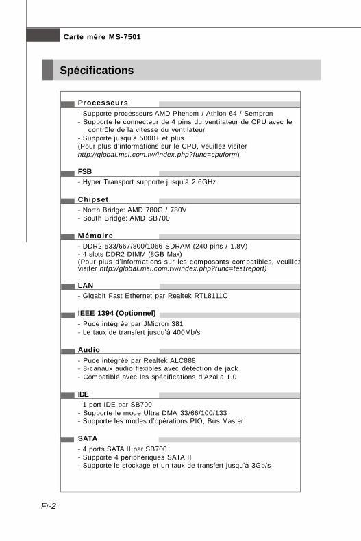
Processeurs- Supporte processeurs AMD Phenom / Athlon 64 / Sempron- Supporte le connecteur de 4 pins du ventilateur de CPU avec le
contrôle de la vitesse du ventilateur- Supporte jusqu’à 5000+ et plus(Pour plus d’informations sur le CPU, veuillez visiterhttp://global.msi.com.tw/index.php?func=cpuform)
FSB- Hyper Transport supporte jusqu’à 2.6GHz
Chipset- North Bridge: AMD 780G / 780V- South Bridge: AMD SB700
M émoire- DDR2 533/667/800/1066 SDRAM (240 pins / 1.8V)- 4 slots DDR2 DIMM (8GB Max)(Pour plus d’informations sur les composants compatibles, veuillezvisiter http://global.msi.com.tw/index.php?func=testreport)
LAN- Gigabit Fast Ethernet par Realtek RTL8111C
IEEE 1394 (Optionnel)- Puce intégrée par JMicron 381- Le taux de transfert jusqu’à 400Mb/s
Audio- Puce intégrée par Realtek ALC888- 8-canaux audio flexibles avec détection de jack- Compatible avec les spécifications d’Azalia 1.0
IDE- 1 port IDE par SB700- Supporte le mode Ultra DMA 33/66/100/133- Supporte les modes d’opérations PIO, Bus Master
SATA- 4 ports SATA II par SB700- Supporte 4 périphériques SATA II- Supporte le stockage et un taux de transfert jusqu’à 3Gb/s
PDF created with pdfFactory Pro trial version www.pdffactory.com

Fr-3
Fran
çais
Disquette- 1 port de disquette- Supporte 1 FDD avec 360KB, 720KB, 1.2MB, 1.44MB et 2.88MB
Connecteurs
Panneau arrière- 1 port souris PS/2- 1 port clavier PS/2- 1 port IEEE 1394 (Optionnel)- 4 ports USB 2.0- 1 jack Gigabit LAN- 1 port VGA- 1 port DVI (Optionnel)- 1 port HDMI (Optionnel)- 6 jacks audio flexibles
Connecteurs intégrés- 3 connecteurs USB 2.0- 1 connecteur IEEE 1394 (Optionnel)- 1 connecteur TPM (Optionnel)- 1 connecteur de port sérial- 1 connecteur CD-In- 1 connecteur SPDIF-Out- 1 connecteur chassis intrusion switch- 1 connecteur panneau avant
Slots- 1 slot PCI Express x16- 1 slot PCI Express x1- 2 slots 32-bit/33MHz PCI
Dimension- M-ATX (24.4cm X 24.4 cm)
Montage- 6 trous de montage
PDF created with pdfFactory Pro trial version www.pdffactory.com
Fr-4
Carte mère MS-7501
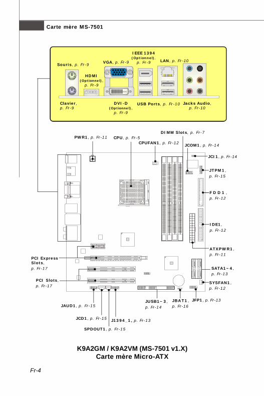
DIMM Slots, p. Fr-7
CPUFAN1, p. Fr-12CPU, p. Fr-5PWR1, p. Fr-11
ATXPWR1,p. Fr-11
IDE1,p. Fr-12
SATA1~4,p. Fr-13
PCI ExpressSlots,p. Fr-17
JBAT1,p. Fr-16
JTPM1,p. Fr-15
JCI1, p. Fr-14
SYSFAN1,p. Fr-12
PCI Slots,p. Fr-17
JUSB1~3,p. Fr-14
F D D 1 ,p. Fr-12
JFP1, p. Fr-13
J1394_1, p. Fr-13JCD1, p. Fr-15
JAUD1, p. Fr-15
SPDOUT1, p. Fr-15
JCOM1, p. Fr-14
K9A2GM / K9A2VM (MS-7501 v1.X)Carte mère Micro-ATX
Souris, p. Fr-9
Clavier,p. Fr-9
HDMI(Optionnel),
p. Fr-9
DVI-D(Optionnel),
p. Fr-9
VGA, p. Fr-9
IEEE 1394(Optionnel),
p. Fr-9 LAN, p. Fr-10
USB Ports, p. Fr-10 Jacks Audio,p. Fr-10
PDF created with pdfFactory Pro trial version www.pdffactory.com

Fr-5
Fran
çais
Unité centrale (CPU)
Important
SurchauffeLa surchauffe endommage sérieusement l’unité centrale et le système.Assurez-vous toujours que le ventilateur de refroidissement fonctionnecorrectement pour protéger l’unité centrale contre la surchauffe. Assurez-vous d’appliquer une couche d’enduit thermique (ou film thermique) entrel’unité centrale et le dissipateur thermique pour améliorer la dissipation dela chaleur.
Remplacement de l’unité centraleLorsque vous remplacez l’unité centrale, commencez toujours par couperl’alimentation électrique de l’ATX ou par débrancher le cordon d’alimentationde la prise mise à la terre pour garantir la sécurité de l’unité centrale.
La carte mère supporte les processeurs AMD®. Le socket AM2/AM2+ permet une instal-lation facile du CPU. Assurez-vous que l’unité centrale soit équipée d’un ventilateur derefroidissement attaché sur le dessus pour éviter la surchaffe. Si vous n’en avez pas,contactez votre revendeur pour en acheter et installez les avant d’allumer votre ordinateur.Pour les dernières informations sur le CPU, veuillez visiter http://global.msi.com.tw/index.php?func=cpuform
Procédure d’installation de CPU pour Socket AM2/ AM2+1. Veuillez éteindre l ’alimentation et en débrocher le cordon
avant d’ installer le CPU.2. Tirez le levier vers le haut et assurez-vous que celui-ci est
bien en position ouverte maximum (angle de 90-degree).3. Recherchez la flèche dorée (gold arrow) du CPU. Il faut
que la flèche dorée dirige comme montrée dans le dessin.Le CPU ne peut être installé que dans un seul sens.
4. Si le CPU est correctement installé, les pins doivent êtrecomplément enfoncés et ne sont plus visibles. Unemauvaise installation pourrait entraîner des dommages vis-à-vis de la carte mère.
5. Mettez le CPU fermement dans la douille et fermez le levier. Il est possible que leCPU bouge quand vous fermez levier. Alors veuillez toujours le fermez en appuyantfermement sur le haut du CPU avec l’autre main afin d’assurer qu’il est correctementet complément enfoncé dans la douille.
Gold arrow
Correct CPUplacement
PDF created with pdfFactory Pro trial version www.pdffactory.com
Fr-6
Carte mère MS-7501
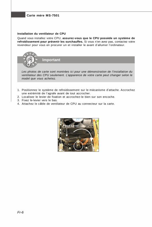
Installation du ventilateur de CPUQuand vous installez votre CPU, assurez-vous que le CPU possède un système derefroidissement pour prévenir les surchauffes. Si vous n’en avez pas, contactez votrerevendeur pour vous en procurer un et installer le avant d’allumer l’ordinateur.
1. Positionnez le système de refroidissement sur le mécanisme d’attache. Accrochezune extrémité de l ’agrafe avant de tout accrocher.
2. Localisez le levier de fixation et accrochez-le bien sur son encoche.3. Fixez le-levier vers le bas.4. Attachez le câble de ventilateur de CPU au connecteur sur la carte.
Fixed Lever
Important
Les photos de carte sont montrées ici pour une démonstration de l’installation duventilateur des CPU seulement. L’apparence de votre carte peut changer selon lemodel que vous achetez.
PDF created with pdfFactory Pro trial version www.pdffactory.com

Fr-7
Fran
çais
Mémoire
Règles de population des mémoires à canal doubleEn mode de Canal double, les modules de mémoire peuvent transmettre et recevoirles données avec simultanément deux lignes omnibus de données. L’activation dumode de Canal double peut amél iorer les performances du système. Veuillez vousreporter aux illustrations suivantes pour connaître les règles de population en modede Canal double.
Ces slots de DIMM (module de mémoire à double rangée de connexion) sont destinésà installer les modules de mémoire.Pour plus d’informations sur les composants compatibles, veuillez visiter http://global.msi.com.tw/index.php?func=testreport
DDR2240-pin, 1.8V
64x2=128 pin56x2=112 pin
1 DIMM1 DIMM2
DIMM3
DIMM4
2 DIMM1
DIMM2
DIMM3
DIMM4
3 DIMM1
DIMM2
DIMM3
DIMM4
EmptyInstalled
PDF created with pdfFactory Pro trial version www.pdffactory.com
Fr-8
Carte mère MS-7501
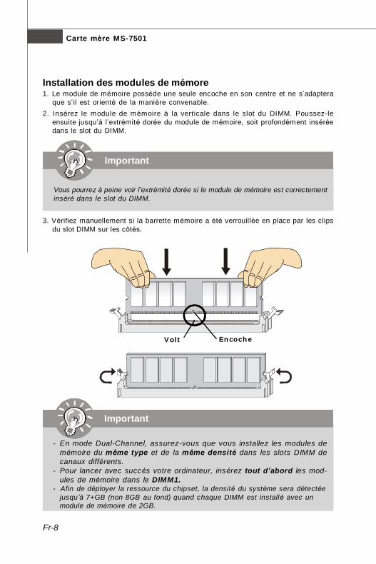
Installation des modules de mémore1. Le module de mémoire possède une seule encoche en son centre et ne s’adaptera
que s’ il est orienté de la manière convenable.2. Insérez le module de mémoire à la verticale dans le slot du DIMM. Poussez-le
ensuite jusqu’à l’extrémité dorée du module de mémoire, soit profondément inséréedans le slot du DIMM.
3. Vérifiez manuellement si la barrette mémoire a été verrouillée en place par les clipsdu slot DIMM sur les côtés.
Important
Vous pourrez à peine voir l’extrémité dorée si le module de mémoire est correctementinséré dans le slot du DIMM.
Volt Encoche
Important
- En mode Dual-Channel, assurez-vous que vous installez les modules demémoire du même type et de la même densité dans les slots DIMM decanaux différents.
- Pour lancer avec succès votre ordinateur, insérez tout d’abord les mod-ules de mémoire dans le DIMM1.
- Afin de déployer la ressource du chipset, la densité du système sera détectéejusqu’à 7+GB (non 8GB au fond) quand chaque DIMM est installé avec unmodule de mémoire de 2GB.
PDF created with pdfFactory Pro trial version www.pdffactory.com

Fr-9
Fran
çais
Port IEEE1394 (Optionnel)Le port IEEE1394 sur le panneau arrière fournit une connexion aux périphériquesIEEE1394.
Panneau arrière
Souris/ClavierLe standard connecteur de souris/clavier DIN de PS/2® est pour une souris ou un clavierde PS/2®.
Connecteur de souris de PS/2 (Vert/ 6-pin féminin)
Connecteur de clavier de PS/2 (Violet/ 6-pin féminin)
Port HDMI (Optionnel)Le High-Definition Multimedia Interface (HDMI) est un interface d’audio-vidéo tout-numérique, capable de trasmettre les flux décompressés. HDMI supporte toute forme deTV, y compris le standard, l’intégré, ou le vidéo high-definition, avec l’audio numériquede multi-canaux sur un câble simple.
Port VGALe connecteur féminin de DB15-pin est fournit pour le moniteur.
Port DVI (Optionnel)Le connecteur DVI (Digital Visual Interface) vous permet de connecter un moniteurLCD. Il founit une interconnexion numérique de haute vitesse entre l’ordinateur et sespériphériques de l ’écran. Afin de connecteur un moniteur de LCD, vous n’avez qu’àbrancher votre câble de moniteur dans le connecteur DIV, et vous assurer que l’autrecôté du câble est correctement connecté ) votre moniteur ( Veuillez vous référer aumanuel de votre moniteur pour plus d’ informations).
PDF created with pdfFactory Pro trial version www.pdffactory.com
Fr-10
Carte mère MS-7501
LANLa prise standard RJ-45 LAN sert à la connexion au réseau local (Local Area Network(LAN)). Vous pouvez y relier un câble de réseau.
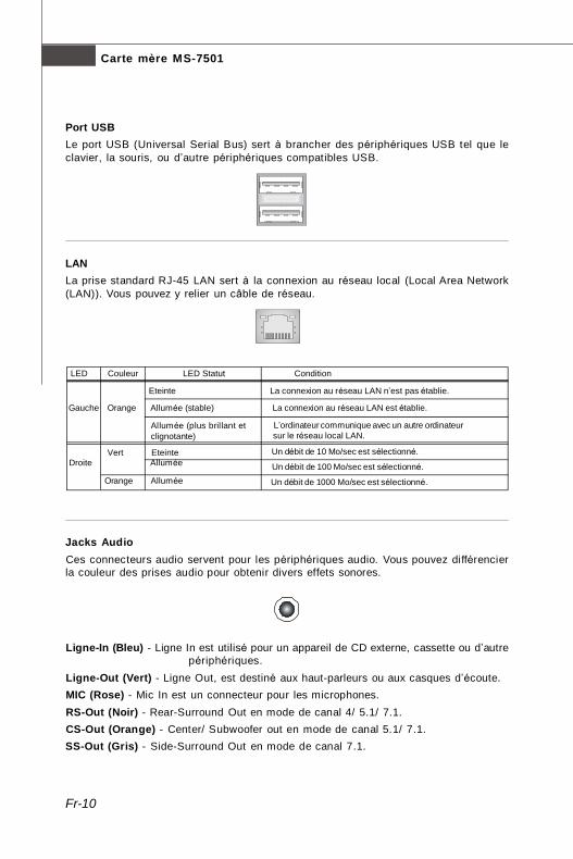
Port USBLe port USB (Universal Serial Bus) sert à brancher des périphériques USB tel que leclavier, la souris, ou d’autre périphériques compatibles USB.
Jacks AudioCes connecteurs audio servent pour les périphériques audio. Vous pouvez différencierla couleur des prises audio pour obtenir divers effets sonores.
Ligne-In (Bleu) - Ligne In est utilisé pour un appareil de CD externe, cassette ou d’autrepériphériques.
Ligne-Out (Vert) - Ligne Out, est destiné aux haut-parleurs ou aux casques d’écoute.MIC (Rose) - Mic In est un connecteur pour les microphones.RS-Out (Noir) - Rear-Surround Out en mode de canal 4/ 5.1/ 7.1.CS-Out (Orange) - Center/ Subwoofer out en mode de canal 5.1/ 7.1.SS-Out (Gris) - Side-Surround Out en mode de canal 7.1.
Un débit de 10 Mo/sec est sélectionné.
Un débit de 100 Mo/sec est sélectionné.
Un débit de 1000 Mo/sec est sélectionné.
Vert Eteinte
LED Couleur LED Statut Condition
Allumée (plus brillant etclignotante)
Gauche Orange Allumée (stable) La connexion au réseau LAN est établie.
Eteinte La connexion au réseau LAN n’est pas établie.
L’ordinateur communique avec un autre ordinateur sur le réseau local LAN.
Droite Allumée
Orange Allumée
PDF created with pdfFactory Pro trial version www.pdffactory.com

Fr-11
Fran
çais
Attachement d’Alimentation d’ÉnergieAvant d’insérer le connecteur d’alimentation d’énergie, assurez-vous toujours que tousles composants sont installés correctement afin de ne pas causer de dommage. Tousles connecteurs de puissance sur la carte mère doivent se relier à l’alimentation d’énergied’ATX et doivent travailler ensemble pour une opération stable.
Connecteur d’alimentation ATX 24-PinCe connecteur vous permet de connecter l’alimentation ATX 24-pin. Pour cela, assurez-vous que la prise d’alimentation est bien positionnée dans le bon sens et que lesgoupilles soient alignées. Enfoncez alors la prise dans le connecteur.Vous pourvez aussi utiliser un alimentation 20-pin selon vos besoins. Veuillez branchervotre alimentation d’énergie avec le pin 1 et le pin 13 si vous voulez utiliser l’alimentationATX 20-pin.
Connecteur d’alimentation ATX 12VLe connecteur d’alimentation de 12V fournit de l ’alimentation au CPU.
Connecteurs, Cavaliers, Slots
PWR14
21
3
12VGND
12VGND
1
12 24
13+3.3V+3.3VGND+5V
GND+5V
GNDPWR OK
5VSB+12V+12V
+3.3V GND+5V+5V+5VNCGNDGNDGNDPS-ON#GND-12V+3.3V
ATXPWR1
PDF created with pdfFactory Pro trial version www.pdffactory.com

Fr-12
Carte mère MS-7501
Connecteur Floppy Disk DriveCe connecteur supporte le lecteur de disquette de 360KB, 720KB,1.2MB, 1.44MB ou 2.88MB.
Connecteur IDECe connecteur supporte les lecteurs de disque dur IDE, lecteurs optiquesde disque et d’autre périphériques IDE.
Important
Si vous installez deux périphériques IDE sur le même câble, vous devez configurerles périphériques séparément en mode Master/ Slave par les cavaliers deconfiguration. Référez-vous aux documentations des périphériques de IDE offertespar votre vendeur pour les instructions de configurations des cavaliers.
FDD1
Connecteurs d’alimentation du ventilateurLes connecteurs de courant du ventilateur supportent le ventilateur de refroidissement dusystème avec +12V. Le ventilateur du CPU supporte la fonction de Smart FAN. Lors dubranchement des fils aux connecteurs, faites toujours en sorte que le fil rouge soit le filpositif devant être relié au connecteur +12V; et que le fil noir soit le fil de mise à la terredevant être relié au connecteur de mise à la terre GND. Si la carte mère est équipée d’unjeu de puces intégré pour moniteur de matériel de système, vous devrez utiliser unventilateur spécial pourvu d’un capteur de vitesse afin de contrôler le ventilateur del’unité centrale.
+12VGND
+12V
IDE1
Important
1. Veuillez consulter les ventilateurs d’unité centrale recommandés sur les sitesofficiels des fabricants de processeurs ou bien consultez votre revendeurpour obtenir des informations sur le ventilateur de refroidissement adapté àvotre unité centrale.
2. Le CPUFAN (ventilateur de processeur) accepte la commande du ventilateur.3. Ventilateur avec 3 ou 4 broches sont tous deux disponibles pour CPUFAN.
CPUFAN1
SE
NS
OR
GN
D
CO
NTRO
L
SYSFAN1
SENSOR
PDF created with pdfFactory Pro trial version www.pdffactory.com

Fr-13
Fran
çais
Conncteur du panneau avantCe connecteur est fourni pour la connecxion électrique aux interrupteus et LEDs dupanneau avant. Il est conforme au guide de conception de la connectivité Entrée/sortiedu panneau avant Intel®.
Connecteur IEEE1394Ce connecteur vous permet de relier un appareil IEEE1394 via un support optionnelIEEE1394.
Connecteur Serial ATACe connecteur est un port d’interface de série ATA haut débit. Chaque connecteur peutêtre relié à un appareil de série ATA.
Important
Veuillez ne pas plier le câble de série ATA à 90°. Autrement des pertes dedonnées pourraient se produire pendant la transmission.
IEEE1394 Bracket(Optionnel)
12
910
HDDLED
ResetSwitch
PowerLED
PowerSwitch
+ +
+
- -
-
JFP1
1 2
9 10
TPA
-G
roun
dTP
B-
Cab
le po
wer
Gro
und
TPA+
Gro
und
TPB
+C
able
pow
erK
ey (n
o pi
n)
J1394_1
PDF created with pdfFactory Pro trial version www.pdffactory.com
Fr-14
Carte mère MS-7501
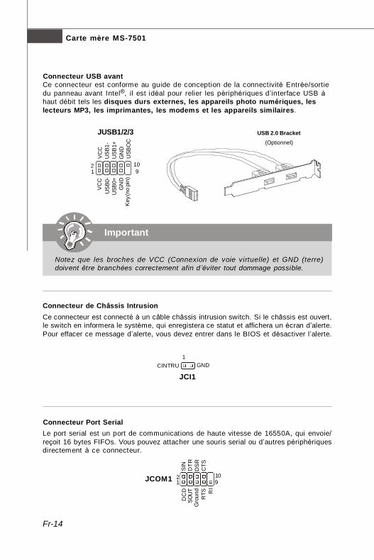
Connecteur USB avantCe connecteur est conforme au guide de conception de la connectivité Entrée/sortiedu panneau avant Intel®, il est idéal pour relier les périphériques d’interface USB àhaut débit tels les disques durs externes, les appareils photo numériques, leslecteurs MP3, les imprimantes, les modems et les appareils similaires.
Important
Notez que les broches de VCC (Connexion de voie virtuelle) et GND (terre)doivent être branchées correctement afin d’éviter tout dommage possible.
USB 2.0 Bracket(Optionnel)
Connecteur de Châssis IntrusionCe connecteur est connecté à un câble châssis intrusion switch. Si le châssis est ouvert,le switch en informera le système, qui enregistera ce statut et affichera un écran d’alerte.Pour effacer ce message d’alerte, vous devez entrer dans le BIOS et désactiver l’alerte.
Connecteur Port SerialLe port serial est un port de communications de haute vitesse de 16550A, qui envoie/reçoit 16 bytes FIFOs. Vous pouvez attacher une souris serial ou d’autres périphériquesdirectement à ce connecteur.
USB
OC
10 1 2
VC
CU
SB0
-U
SB0+
GN
DK
ey (n
o pi
n)
VC
CU
SB1
-U
SB1+
GN
D
9
JUSB1/2/3
CINTRU GND1
JCI1
1 92
DC
DS
INSO
UT
DTR
Gro
und
DS
RR
TSC
TSR
I
10JCOM1
PDF created with pdfFactory Pro trial version www.pdffactory.com

Fr-15
Fran
çais
Connecteur TPM ModuleCe connecteur est rélié à TPM (Trusted Platform Module) Module (optionnel). Veuillezvous référer au manuel de TPM plat-forme de sécurité pour plus de détails et d’utilisations.
Connecteur S/PDIF-OutCe connecteur est utilisé pour relier à l ’interface S/PDIF (Sony & Philips Digital Inter-connect Format) de la transmission audio numérique.
SPDOUT1
VCC
SPDIF
GND
Connecteur audio panneau avantCe connecteur vous permet de connecter un audio sur le panneau avant. Il est conformeau guide de conception de la connectivité Entrée/sortie du panneau avant Intel®.
12
910
MIC
_L
MIC
_R
LIN
E o
ut_R
Fron
t_JD
LIN
E o
ut_L
Gro
und
NC
MIC
_JD
NC
(No
pin)
LIN
E o
ut_J
D
JAUD1
Connecteur CD-InCe connecteur est fournit pour un audio externe d’entrer.
GND RL
JCD1
21
1413
3Vdual / 3V_STB LCLKLRST#LAD0LAD1LAD2LAD3LFRAME#
VCC3SIRQVCC5
Key(no pin)GNDGND
JTPM1
PDF created with pdfFactory Pro trial version www.pdffactory.com

Fr-16
Carte mère MS-7501
Cavalier d’effacement du CMOSI l y a un CMOS RAM intégré, qui possède un bloc d’alimentation alimenté par unebatterie externe, destiné à conserver les données de configuration du système. Avec leCMOS RAM, le système peut lancer automatiquement le système d’exploitation chaquefois qu’ il est allumé. Si vous souhaitez effacer la configuration du système, réglez lecavalier de manière à effacer les données.
Important
Vous pouvez effacer le CMOS en raccourcissant 2-3 broches quand le systèmeest éteint. Retournez ensuite en position 1-2 broches. Evitez d’effacer le CMOSpendant que le système est allumé; cela endommagerait la carte mère.
Effacer les données
1 3
Conserver les données
1 3
JBAT11
PDF created with pdfFactory Pro trial version www.pdffactory.com
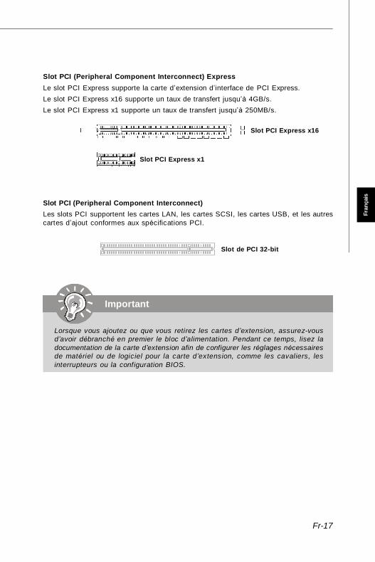
Fr-17
Fran
çais
Important
Lorsque vous ajoutez ou que vous retirez les cartes d’extension, assurez-vousd’avoir débranché en premier le bloc d’alimentation. Pendant ce temps, lisez ladocumentation de la carte d’extension afin de configurer les réglages nécessairesde matériel ou de logiciel pour la carte d’extension, comme les cavaliers, lesinterrupteurs ou la configuration BIOS.
Slot PCI (Peripheral Component Interconnect) ExpressLe slot PCI Express supporte la carte d’extension d’interface de PCI Express.Le slot PCI Express x16 supporte un taux de transfert jusqu’à 4GB/s.Le slot PCI Express x1 supporte un taux de transfert jusqu’à 250MB/s.
Slot PCI (Peripheral Component Interconnect)Les slots PCI supportent les cartes LAN, les cartes SCSI, les cartes USB, et les autrescartes d’ajout conformes aux spécifications PCI.
Slot de PCI 32-bit
Slot PCI Express x16
Slot PCI Express x1
PDF created with pdfFactory Pro trial version www.pdffactory.com

Fr-18
Carte mère MS-7501
Réglages BIOS
Ce chapitre donne des informations concernant le programme de réglage de BIOS etvous permet de configurer le système pour obtenir des performances d’utilisationoptimum. Vous aurez peut-être besoin de lancer le programme de réglage quand :* Un message d’erreur apparaît sur l’écran pendant le démarrage du système, qui vous
demande de lancer SETUP (Réglage).* Vous souhaitez changer les réglages par défaut des fonctions personnalisées.
Important
1.Les objets situés sous chaque catégorie BIOS décrits dans ce chapitre sont encours de mise à jour continue pour amél iorer les performances du système.C'est pourquoi il est possible que la description soit légèrement différente duBIOS le plus récent, et ne doit servir que comme référence.
2.Au redémarrage, la première ligne qui apparaît après le compte de la mémoire,est la version BIOS. Elle est généralement sous la forme :
A7501AMS V1.0 062508 où:Le premier caractère se rapporte au fabricant du BIOS : A = AMI, W = AWARD, et P = PHOENIX.Le sixième caractère se rapporte au jeu de puces : A = ATi, I = Intel, V = VIA, N = Nvidia, U = ULi.Les septième et huitième caractère se rapportent au client : MS = all standard customers (Tous les clients standard).V1.0 se rapporte à la version de BIOS.062508 se rapporte à la date à laquelle est sortie ce BIOS.
PDF created with pdfFactory Pro trial version www.pdffactory.com

Fr-19
Fran
çais
Réglages d’EntréeAllumez l'ordinateur et le système lancera le processus POST (Test automatiqued'allumage). Lorsque le message ci-dessous apparaît à l'écran, appuyez sur la touche<DEL> pour entrer dans les réglages.
Appuez sur DEL pour entrer dans SETUP (Réglages)Si le message disparaît avant que vous ne répondiez et que vous souhaitez encoreentrer dans Setup (Réglages), redémarrez le système en OFF (éteignant) puis en On(rallumant) en appuyant sur le bouton RESET (Réinitialiser). Vous pouvez égalementredémarrer le système en appuyant simultanément sur les touches <Ctrl>, <Alt>, et<Delete>.
Obtenir de l’aideAprès être entré dans le menu de Réglage, le premier menu que vous verrez apparaîtresera le menu principal.
Menu principalLe menu principal établit la liste des fonctions de réglage que vous pouvez modifier.Vous pouvez util iser les touches de flèche (↑↓ ) poursélectionner l'objet. La description en ligne des fonctions deréglages illuminées est affichée au bas de l'écran.
Sous-MenuSi vous un symbole de pointeur droit (comme indiqué sur la vue de droite) apparaît surla gauche de certains champs, cela signifie qu'un sous-menu peut être lancé à partir dece champ. Un sous-menu contient des options supplémentaires pour un paramètre dechamp. Vous pouvez utiliser les touches de flèche (↑↓ ) pour illuminer le champ puisappuyez sur <Enter> (Entrer) pour faire apparaître le sous-menu. Vous pourrez alorsutiliser les touches de commande pour saisir des valeurs et vous déplacer d'un champà un autre à l' intérieur d'un sous-menu. Si vous souhaitez revenir au menu principal,appuyez juste sur <Esc>.
Aide générale <F1>Le programme de réglages BIOS fournit un écran d'aide générale. Vous pouvez fairesortir cet écran à partir de n'importe quel menu en appuyant simplement sur <F1>.L'écran d'aide donne une liste des touches appropriées à utiliser et les sélectionspossibles pour l'objet illuminé. Appuyez sur <Esc> pour quitter l'écran d'aide.
PDF created with pdfFactory Pro trial version www.pdffactory.com

Fr-20
Carte mère MS-7501
Menu principalUne fois entré dans l ’unité de réglages BIOS CMOS, le Menu principal appaît surl’écran. Le Menu Principal vous permet de sélectionner de dix foncions de réglage etdeux choix de sortie. Utilisez les touches de flèche pour sélectionner parmi les objets etappuyez sur <Enter> pour accepter ou entrer dans le sous-menu.
Standard CMOS Features (Fonctions CMOS standard)Utilisez ce menu pour les configurations du système de base, tel que l’heure, la date.
Advanced BIOS Features (Fonctions BIOS avancées)Utilisez ce menu pour régler les objets des fonctions amél iorées spéciales AMI®.
Integrated Peripherals (Périphériques intégrés)Utilisez ce menu pour définir vos régléges des périphériques intégrés.
Power Management Setup (Réglages de la gestion de l’énergie)Utilisez ce menu pour définir vos réglages de la gesion de l’énergie.
H/W Monitor (Moniteur H/W)Cette entrée indique l’état de santé de votre PC.
Cell Menu (Menu cell)Utilisez ce menu pour définir vos réglages du contrôle de la fréquence/voltage et del ’overclocking.
Load Fail-Safe Defaults (Défauts de sécurité de chargement intégrée)Utilisez ce menu pour charger les valeur par défauts réglées par le vendeur de BIOSafin de garantir la stabilité des performances du système.
Load Optimized Defaults (Chargement des réglages par défaut optimisés)Utilisez ce menu pour charger les valeurs par défaut réglées par le fabricant de la cartemère spécifiquement pour obtenir des performances optimales de la carte mère.
BIOS Setting Password (Mot de passe de réglage BIOS)Utilisez ce menu pour régler le mot de passe.
Save & Exit Setup (Sauvegarder et quitter les réglages)Sauvegardez les changements apportés au CMOS puis quittez les réglages.
Exit Without Saving (Quitter sans sauvegarder)Abandonnez tous les changements et quittez les réglages.
PDF created with pdfFactory Pro trial version www.pdffactory.com
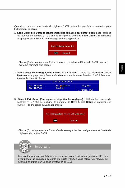
Fr-21
Fran
çais
Quand vous entrez dans l’unité de réglages BIOS, suivez les procédures suivantes pourl ’utilisation générale.1. Load Optimized Defaults (chargement des réglages par défaut optimisés) : Utilisez
les touches de contrôle (↑↓ ) afin de surligner le domaine Load Optimized Defaultset appuyez sur <Enter> , le message suivant apparaîtra :
Choisir [Ok] et appuyer sur Enter chargera les valeurs défauts de BIOS pour unsystème minimal plus stable.
2. Setup Date/ Time (Réglage de l’heure et de la date) : Choisissez Standard CMOSFeatures et appuyez sur <Enter> afin d’entrer dans le menu Standard CMOS Features.Ajustez la date et l ’heure.
3. Save & Exit Setup (Sauvegarder et quitter les réglages) : Utilisez les touches decontrôle (↑↓ ) afin de surligner le domaine de Save & Exit Setup et appuyez sur<Enter> , le message suivant apparaîtra :
Choisir [Ok] et appuyer sur Enter afin de sauvegarder les configurations et l’unité deréglages de quitter BIOS.
Important
Les configurations précédantes ne sont que pour l’utilisation générale. Si vousavez besoin de réglages détaillés du BIOS, veuillez vous référer au manuel del’édition anglaise sur la page d’internet de MSI.
PDF created with pdfFactory Pro trial version www.pdffactory.com
Fr-22
Carte mère MS-7501
Information de Logiciel
Sortez le pilote/ Service du CD, qui est inclus dans le paquet de la carte mère etplacez-le dans le CD-ROM.L’ installation va automatiquement se déclencher, cliquezsur le pilote ou sur l ’usage et suivez le pop-up de l’écran pour accomplir l’installation.Le pilote/Service CD contient :
Menu de pilote – I l montre les pilotes disponibles. Installez le pilote si vous le souhaitez pour activer le dispositif.
Menu de services – Il montre les applications logicielles supportées par la carte mère.Menu du site Web – Il vous indique les sites webs utiles.
Important
Veuillez consulter le site Web de MSI pour obtenir les derniers pilotes et BIOSpour amél iorer l’exécution du système de votre ordinateur.
PDF created with pdfFactory Pro trial version www.pdffactory.com

Ru-1
Русский
K9A2GM / K9A2VMРуководствопользователя
Русский
PDF created with pdfFactory Pro trial version www.pdffactory.com

Ru-2
MS-7501 Системная плата
Характеристики
Процессор- Процессоры AMD Phenom / Athlon 64 / Sempron- Поддержка 4-конт вентилятора процессора с функциейуправления скоростью вращения
- Поддержка процессоров до 5000+ и выше(Для получения самой новой информации о CPU, посетите сайтhttp://global.msi.com.tw/index.php?func=cpuform)
FSB- Hyper Transport поддерживает скорость до 2.6 GHz
Чипсет- Северный мост: AMD 780G / 780V- Южный мост: AMD SB700
Память- DDR2 533/667/800/1066 SDRAM (240 конт / 1.8В)- 4 слота DDR2 DIMM (8ГБ Max)(За дополнительной информацией о совместимых компонентахпосетите сайт http://global.msi.com.tw/index.php?func=testreport)
LAN- Поддержка Gigabit Fast Ethernet на микросхеме Realtek
RTL8111C
IEEE 1394 (опционально)
- Интегрированный чипсет JMicron 381- Скорость передачи данных до 400Мб/с
Аудио- Интегрированный чипсет Realtek ALC888- 8-канальное аудио с гибким переназначением разъемов- Совместимость со спец. Azalia 1.0
IDE- 1 порт IDE by на чипсете SB700- Поддержка режимов Ultra DMA 33/66/100/133- Поддержка режимов работы PIO, Bus Master
SATA- 4 порта SATA II на чипсете SB700- Поддержка 4 устройств SATA II- Поддержка скорости передачи данных до 3Гб/с
PDF created with pdfFactory Pro trial version www.pdffactory.com

Ru-3
Русский
Флоппи- 1 флоппи порт- Поддержка 1 FDD с 360KB, 720KB, 1.2MB, 1.44MB и 2.88MB
КоннекторыЗадней панели- 1 PS/2 порт мыши- 1 PS/2 порт клавиатуры- 1 порт IEEE 1394 (опционально)- 4 порта USB 2.0- 1 Gigabit разъем LAN- 1 порт VGA- 1 порт DVI (опционально)- 1 порт HDMI (опционально)- 6 звуковых разъемов с гибким переназначением
Разъемы, установленные на плате- 3 разъема USB 2.0- 1 разъем IEEE 1394 (опционально)- 1 разъем TPM (опционально)- 1 COM порт- 1 разъем CD-In- 1 разъем SPDIF-Out- 1 разъем датчика открывания корпуса- 1 разъем на передней панели
Слоты- 1 слот PCI Express x16- 1 слот PCI Express x1- 2 слота PCI 32-bit/33MHz
Форм Фактор- M-ATX (24.4см X 24.4 см)
Крепление- 6 отверстий для крепления
PDF created with pdfFactory Pro trial version www.pdffactory.com

Ru-4
MS-7501 Системная плата
DIMM Slots, p. Ru-7
CPUFAN1, p. Ru-12CPU, p. Ru-5PWR1, p. Ru-11
ATXPWR1,p. Ru-11
IDE1,p. Ru-12
SATA1~4,p. Ru-13
PCI ExpressSlots,p. Ru-17
JBAT1,p. Ru-16
JTPM1,p. Ru-15
JCI1, p. Ru-14
SYSFAN1,p. Ru-12
PCI Slots,p. Ru-17
JUSB1~3,p. Ru-14
F D D 1 ,p. Ru-12
J1394_1, p. Ru-13JCD1, p. Ru-15
JAUD1, p. Ru-15
SPDOUT1, p. Ru-15
JCOM1, p. Ru-14
K9A2GM / K9A2VM (MS-7501 v1.X)Micro-ATX Системная плата
Mouse, p. Ru-9
Keyboard,p. Ru-9
HDMI(Optional),
p. Ru-9
DVI-D(опционально),
p. Ru-9
VGA, p. Ru-9
IEEE 1394(опционально),
p. Ru-9LAN, p. Ru-10
USB Ports, p. Ru-10 Audio Jacks,p. Ru-10
JFP1, p. Ru-13
PDF created with pdfFactory Pro trial version www.pdffactory.com
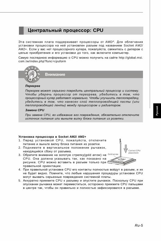
Ru-5
Русский
Центральный процессор: CPU
Внимание
ПерегревПерегрев может серьезно повредить центральный процессор и систему.Чтобы у бер ечь проц ес с ор от пе регр ева , у б едитес ь в том , ч топроцессорный кулер работает нормально. Чтобы улучшить теплопередачу,у бедитес ь в том , что нанес ен слой теплопроводя щей пас ты (илитеплопроводящей ленты) между процессором и радиатором.Замена CPUПри замене CPU, во избежание его повреждения, обязательно отключитеисточник питания или выньте вилку блока питания из розетки.
Эта системная плата поддерживает процессоры от AMD®. Для облегченияустановки процессора на ней установлен разъем под названием Socket AM2/AM2+. Если у вас нет процессорного кулера, пожалуйста, свяжитесь с дилером сцелью приобретения и его установки до того, как включите компьютер.Самую последнюю информацию о CPU можно получить на сайте http://global.msi.com.tw/index.php?func=cpuform
Установка процессора в Socket AM2/ AM2+1. Перед ус тановкой CP U, пожалуйста, отключитепитание и выньте вилку блока питания из розетки.
2. Поднимите в вертикальное положение рычажок ,находящийся сбоку от разъема.
3. Обратите внимание на золотую стрелку(gold arrow) наCPU. Она должна указывать так , как показано нарисунке. CPU можно вставить в разъем только приправильной ориентации.
4. При правильной установке CPU его контакты полностью войдут в разъем, и ихне будет видно. Помните, что любые нарушения процедуры установки CPUмогут вызвать серьезные повреждения системной платы.
5. Аккуратно прижмите CPU к разъему и опустите рычажок. Поскольку CPU приопускании рычажка может переместиться, осторожно прижмите CPU пальцамив центре так, чтобы он правильно и полностью зафиксировался в разъеме.
Gold arrow
Correct CPUplacement
PDF created with pdfFactory Pro trial version www.pdffactory.com

Ru-6
MS-7501 Системная плата
Установка вентилятор для CPUВо избежание перегрева процессора при его работе обязательно установитевентилятор процессора. Не забудьте нанести теплопроводящую пасту на верхнююкрышку процессора перед установкой радиатора/ вентилятора процессора. Еслиу вас нет процессорного вентилятора, пожалуйста, свяжитесь с дилером с цельюприобретения и его установки до того, как включите компьютер.
1. Разместите радиатор на узле крепления. Вначале зацепите один его край.2. Затем нажмите на другой край, чтобы установить радиатор на узел крепления.Найдите рычаг фиксации и поднимите его.
3. Зафиксируйте радиатор дальнейшим поворотом рычага.4. Подключите кабель вентилятор CPU к соответствующему разъему системнойплаты.
Fixed Lever
Внимание
Фото системной платы, размещенные в этой части, приведены толькодля демонстрации установки вентилятора. Общий вид системной платызависит от модели, купленной вами.
PDF created with pdfFactory Pro trial version www.pdffactory.com

Ru-7
Русский
Память
Правила установки модулей памяти для работы вдвухканальном режимеВ двухканальном режимемодули памяти могут передавать и принимать данныепо 2 шинам одновременно. При использовании двухканального режимапроизводительность системы повышается. Ниже приведены правилазаполнения слотов памяти для работы в двухканальном режиме.
Cлоты DIMM используются для установки модулей памяти.За дополнительной информацией о совместимых компонентах поситите сайтhttp://global.msi.com.tw/index.php?func=testreport
DDR2240-конт, 1.8V
64x2=128 конт56x2=112 конт
1 DIMM1 DIMM2
DIMM3
DIMM4
2 DIMM1
DIMM2
DIMM3
DIMM4
3 DIMM1
DIMM2
DIMM3
DIMM4
EmptyInstalled
PDF created with pdfFactory Pro trial version www.pdffactory.com

Ru-8
MS-7501 Системная плата
Установка модулей памяти1. Модули памяти имеют только одну прорезь в середине. Модуль войдет вразьем только при правильной ориентации.
2. Вставьте модуль в DIMM слот в вертикальном направлении. Затем нажмите нанего, чтобы золоченые контакты глубоко погрузились в DIMM слот. Если модульпамяти вставлен правильно, то пластиковые защелки на обоих концахзакроются автоматически.
3. Вручную убедитесь, что модуль закреплен в слоте DIMM защелками с обеихсторон .
Внимание
Золотые контакты едва видны, если модули памяти правильно размещеныв DIMM слоте.
Volt Notch
Внимание
- Для работы в двухканальном режиме убедитесь, что в разъемахразных каналов у вас установлены модлуи одного типа и одинаковойемкости.
- Чтобы система загрузилась, вначале установите модули в разъемыDIM M1.
- Из-за специфики распределения системных ресурсов чипсета, объемдоступной памяти может максимально составить 7+ГБ (но не 8ГБ) приустановке модулей памяти 2ГБ в каждый из слотов .
PDF created with pdfFactory Pro trial version www.pdffactory.com
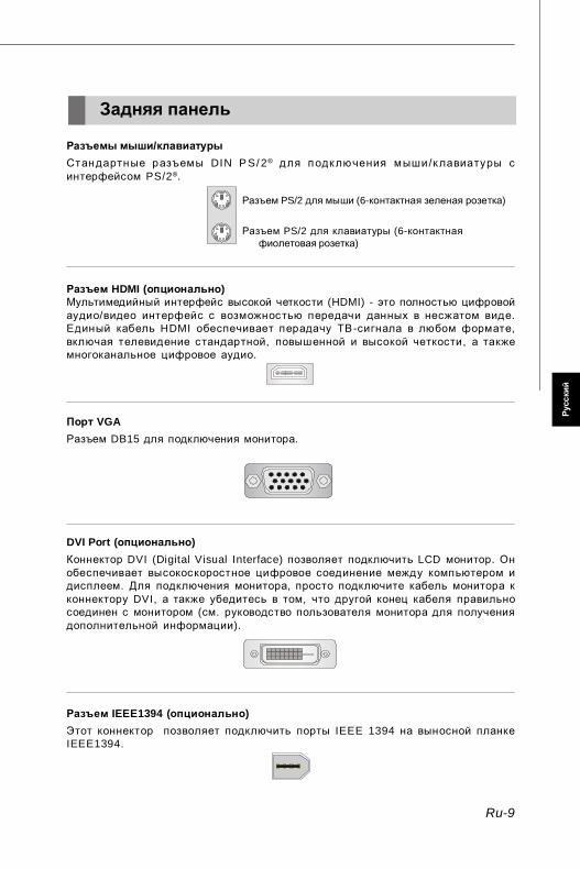
Ru-9
Русский
Разъем IEEE1394 (опционально)Этот коннектор позволяет подключить порты IEEE 1394 на выносной планкеIEEE1394.
Задняя панель
Разъемы мыши/клавиатурыСтандартные разъемы DIN P S/ 2® для подключения мыши /клавиатуры синтерфейсом PS/2®.
Разъем PS/2 для мыши (6-контактная зеленая розетка)
Разъем PS/2 для клавиатуры (6-контактнаяфиолетовая розетка)
Разъем HDMI (опционально)Мультимедийный интерфейс высокой четкости (HDMI) - это полностью цифровойаудио/видео интерфейс с возможностью передачи данных в несжатом виде.Единый кабель HDMI обеспечивает перадачу ТВ -сигнала в любом формате,включая телевидение стандартной, повышенной и высокой четкости , а такжемногоканальное цифровое аудио.
Порт VGAРазъем DB15 для подключения монитора.
DVI Port (опционально)Коннектор DVI (Digital Visual Interface) позволяет подключить LCD монитор. Онобеспечивает высокоскоростное цифровое соединение между компьютером идисплеем. Для подключения монитора, просто подключите кабель монитора кконнектору DVI, а также убедитесь в том, что другой конец кабеля правильносоединен с монитором (см. руководство пользователя монитора для получениядополнительной информации).
PDF created with pdfFactory Pro trial version www.pdffactory.com
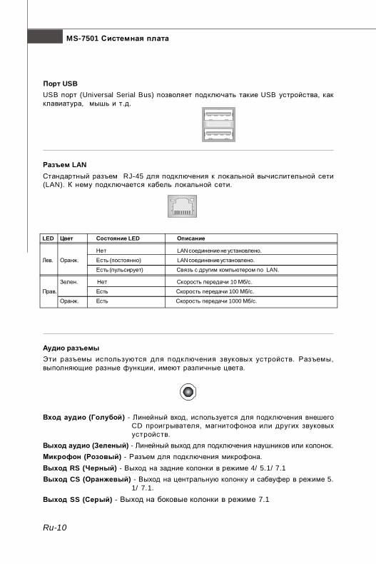
Ru-10
MS-7501 Системная плата
Разъем LANСтандартный разъем RJ-45 для подключения к локальной вычислительной сети(LAN). К нему подключается кабель локальной сети.
LED Цвет Состояние LED Описание
Нет LAN соединение не установлено.
Лев. Оранж. Есть (постоянно) LAN соединение установлено.
Есть (пульсирует) Связъ с другим компьютером по LAN.
Зелен. Нет Скорость передачи 10 Мб/с.
Прав. Есть Скорость передачи 100 Мб/с.
Оранж. Есть Скорость передачи 1000 Мб/с.
Порт USBUSB порт (Universal Serial Bus) позволяет подключать такие USB устройства, какклавиатура, мышь и т.д.
Аудио разъемыЭти разъемы используются для подключения звуковых устройств. Разъемы,выполняющие разные функции, имеют различные цвета.
Вход аудио (Голубой) - Линейный вход, используется для подключения внешегоCD проигрывателя, магнитофоноа или других звуковыхустройств.
Выход аудио (Зеленый) - Линейный выход для подключения наушников или колонок.Микрофон (Розовый) - Разъем для подключения микрофона.Выход RS (Черный) - Выход на задние колонки в режиме 4/ 5.1/ 7.1Выход CS (Оранжевый) - Выход на центральную колонку и сабвуфер в режиме 5.
1/ 7.1.Выход SS (Серый) - Выход на боковые колонки в режиме 7.1
PDF created with pdfFactory Pro trial version www.pdffactory.com

Ru-11
Русский
Подключение источника питанияПеред подключением разъема питания, во избежание повреждений обязательноубедитесь, что все компоненты установлены правильно. Все разъемы питаниядолжны быть подключены к блоку питания ATX для обеспечения стабильнойработы системной платы.
24-контактный разъем питания ATXЭтот разъем позволяет подключить 24-контактный коннектор блока питания ATX.Перед подключением источника питания убедитесь, что его разъем и контактыправильно сориентированы. Затем плотно вставьте его в разъем на системнойплате.Вы также можете использовать 20-контактный ATX блок питания.
Разъем питания ATX 12ВЭтот разъем 12V предназначен для питания CPU.
Соединители, перемычки, разъемы
PWR14
21
3
12VGND
12VGND
1
12 24
13+3.3V+3.3VGND+5V
GND+5V
GNDPWR OK
5VSB+12V+12V
+3.3V GND+5V+5V+5VNCGNDGNDGNDPS-ON#GND-12V+3.3V
ATXPWR1
PDF created with pdfFactory Pro trial version www.pdffactory.com
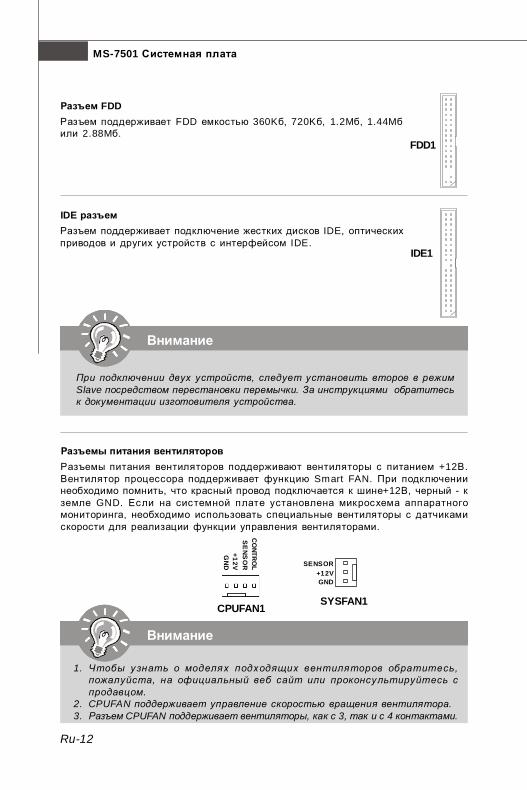
Ru-12
MS-7501 Системная плата
Разъем FDDРазъем поддерживает FDD емкостью 360Kб, 720Kб, 1.2Mб, 1.44Mбили 2.88Mб.
IDE разъемРазъем поддерживает подключение жестких дисков IDE, оптическихприводов и других устройств с интерфейсом IDE.
Внимание
При подключении двух устройств, следует установить второе в режимSlave посредством перестановки перемычки. За инструкциями обратитеськ документации изготовителя устройства.
FDD1
Разъемы питания вентиляторовРазъемы питания вентиляторов поддерживают вентиляторы с питанием +12В.Вентилятор процессора поддерживает функцию Smart FAN. При подключениинеобходимо помнить, что красный провод подключается к шине+12В, черный - кземле GND. Если на системной плате установлена микросхема аппаратногомониторинга, необходимо использовать специальные вентиляторы с датчикамискорости для реализации функции управления вентиляторами.
Внимание
1. Чтобы у знать о моделя х подх одящих вентиля торов обратитесь ,пожалуйста, на официальный веб сайт или проконсу льтируйтесь спродавцом.
2. CPUFAN поддерживает управление скоростью вращения вентилятора.3. Разъем CPUFAN поддерживает вентиляторы, как с 3, так и с 4 контактами.
SYSFAN1
SENSOR+12VGND
IDE1
CPUFAN1
SE
NS
OR
+12VG
ND
CO
NTRO
L
PDF created with pdfFactory Pro trial version www.pdffactory.com

Ru-13
Русский
Коннекторы передней панелиОба эти коннектора используются для подключения кнопок и индикаторов,расположенных на передней панели корпуса. Коннектор JFP1 соответствуетруководству Intel® Front Panel I/O design.
Коннектор IEEE1394Этот коннектор позволяет подключить порты IEEE 1394 на выносной планкеIEEE1394.
Разъем Serial ATAДанный разъем является высокоскоростным портом интерфейса Serial ATA. Любойразъем Serial ATA может соединяться с одним устройством Serial ATA.
Внимание
Избегайте, пожалуйста, резких изгибов кабеля Serial ATA. В противномслучае могут возникнуть потери данных при передаче.
IEEE1394 Bracket(опционально)
12
910
HDDLED
ResetSwitch
PowerLED
PowerSwitch
+ +
+
- -
-
JFP1
1 2
9 10
TPA
-G
roun
dTP
B-
Cab
le po
wer
Gro
und
TPA+
Gro
und
TPB
+C
able
pow
erK
ey (n
o pi
n)
J1394_1
PDF created with pdfFactory Pro trial version www.pdffactory.com
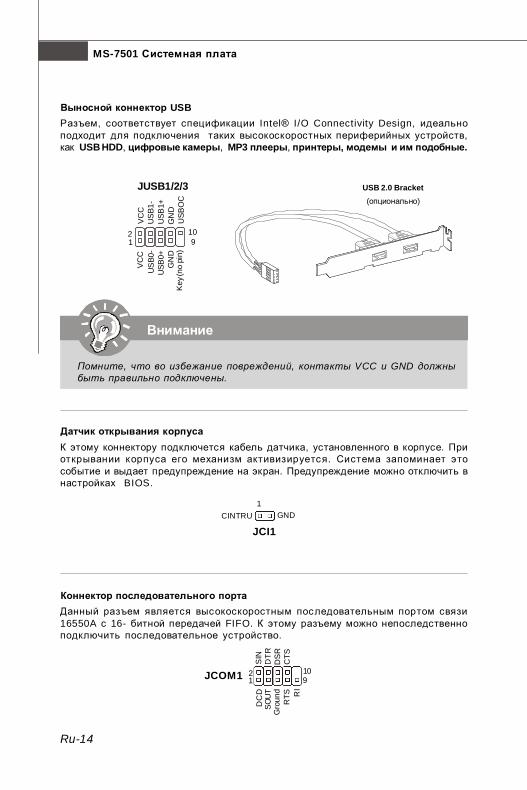
Ru-14
MS-7501 Системная плата
Выносной коннектор USBРазъем, соответствует спецификации Intel® I/O Connectivity Design, идеальноподходит для подключения таких высокоскоростных периферийных устройств,как USB HDD, цифровые камеры, MP3 плееры, принтеры, модемы и им подобные.
Внимание
Помните, что во избежание повреждений, контакты VCC и GND должныбыть правильно подключены.
USB 2.0 Bracket(опционально)
Датчик открывания корпусаК этому коннектору подключется кабель датчика, установленного в корпусе. Приоткрывании корпуса его механизм активизируется. Система запоминает этособытие и выдает предупреждение на экран. Предупреждение можно отключить внастройках BIOS.
Коннектор последовательного портаДанный разъем является высокоскоростным последовательным портом связи16550A с 16- битной передачей FIFO. К этому разъему можно непоследственноподключить последовательное устройство.
USB
OC
10 1 2
VC
CU
SB0
-U
SB0+
GN
DK
ey (n
o pi
n)
VC
CU
SB1
-U
SB1+
GN
D
9
JUSB1/2/3
CINTRU GND1
JCI1
1 92
DC
DS
INSO
UT
DTR
Gro
und
DS
RR
TSC
TSR
I
10JCOM1
PDF created with pdfFactory Pro trial version www.pdffactory.com

Ru-15
Русский
Разъем TPM МодуляДанный разъем подключается к модулю TP M (T rust ed Plat form Module)(опционально). За более подробной информацией и назначениями обращайтеськ Описанию модуля TPM.
Разъем выхода S/PDIFЭтот разъем используется для подключения SPDIF (Формат цифровой передачиот Sony & Philips) - для цифровой передачи звукового сигнала.
SPDOUT1
VCC
SPDIF
GND
Выносной разъем аудиоЭтот коннектор позволяет подключить выносной разъем аудио на передней панелии соответствует руководству Intel® Front Panel I/O Connectivity Design Guide.
12
910
MIC
_L
MIC
_R
LIN
E o
ut_R
Fron
t_JD
LIN
E o
ut_L
Gro
und
NC
MIC
_JD
NC
(No
pin)
LIN
E o
ut_J
D
JAUD1
Разъем CD-InЭтот коннектор предназначен для подключения внешенего входа аудио.
GND RL
JCD1
21
1413
3Vdual / 3V_STB LCLKLRST#LAD0LAD1LAD2LAD3LFRAME#
VCC3SIRQVCC5
Key(no pin)GNDGND
JTPM1
PDF created with pdfFactory Pro trial version www.pdffactory.com

Ru-16
MS-7501 Системная плата
Перемычка сброса CMOSНа плате установлена CMOS память с питанием от батарейки, хранящая данныео конфигурации системы . Данные, хранящиеся в CMOS памяти , требуютсякомпьютеру для загрузки операционной системы при включении. Если у васвозникает необходимость сбросить конфигурацию системы (очистить CMOS),воспользуйтесь этой перемычкой.
Внимание
Очистка CMOS производится соединением контактов 2-3 при отключеннойсистеме. Затем следует вернуться к соединению контактов 1-2. Избегайтеочистки CMOS при работающей системе: это повредит системную плату.
Clear Data
1 3
Keep Data
1 3
JBAT11
PDF created with pdfFactory Pro trial version www.pdffactory.com
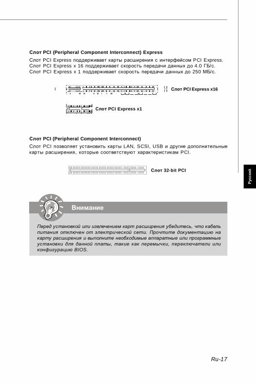
Ru-17
Русский
Внимание
Перед установкой или извлечением карт расширения убедитесь, что кабельпитания отключен от электрической сети. Прочтите документацию накарту расширения и выполните необходимые аппаратные или программныеустановки для данной платы, такие как перемычки, переключатели иликонфигурацию BIOS.
Слот PCI (Peripheral Component Interconnect) ExpressСлот PCI Express поддерживает карты расширения с интерфейсом PCI Express.Слот PCI Express x 16 поддерживает скорость передачи данных до 4.0 ГБ/с.Слот PCI Express x 1 поддерживает скорость передачи данных до 250 МБ/с.
Слот PCI (Peripheral Component Interconnect)Слот PCI позволяет установить карты LAN, SCSI, USB и другие дополнительныекарты расширения, которые соответствуют характеристикам PCI.
Слот 32-bit PCI
Слот PCI Express x16
Слот PCI Express x1
PDF created with pdfFactory Pro trial version www.pdffactory.com
Ru-18
MS-7501 Системная плата
Настройка BIOS
В этой главе приводятся основные сведения о режиме настройки BIOS (BIOSSETUP), который позволяет установить оптимальную конфигурацию системы.Этот режим может потребоваться в следующих случаях:* Во время загрузки системы появляется сообщение об ошибке с требованиемзапустить BIOS SETUP.
* Вы желаете заменить заводские настройки на собственные.
Внимание
1. Для улучшения работы системы содержимое каждого из разделов BIOS,рассматриваемое в данной главе, постоянно совершенствуется . Поэтому,для новых версий BIOS оно может несколько отличаться от данногоописания, которое сможет служить в качестве ориентира.
2. При загрузке , в первой, после объема памяти строке, выводитсяобозначение BIOS . Обычно оно имеет следующий формат:
A7501AMS V1.0 062508 где:1ая буква соответствует изготовителю BIOS ( A = AMI, W = AWARD и P =PHOENIX)Следующие 4 цифры соответствуют номеру модели.Следующая буква обозначает поставщика чипсета (A = AMD, I = Intel, V =VIA, N = Nvidia, U = ULi).2 следующие буквы обозначают заказчика MS = стандартный заказчик.V1.0 соответствует номеру версии BIOS .062508 - дата выпуска BIOS.
PDF created with pdfFactory Pro trial version www.pdffactory.com

Ru-19
Русский
Вход в режим настройкиВключите питание компьютера. При этом запустится процедура POST (Тествключения питания). Когда на экране появится приведенное ниже сообщение,нажмите клавишу <DEL> для входа в режим настройки.
Press DEL to enter SETUPЕсли сообщение исчезло, а вы не успели нажать клавишу, перезапустите систему,выключив и снова включив питание, или нажав кнопку RESET. Можно, также,перезапустить систему, нажав одновременно клавиши <Ctrl>, <Alt>, и <Delete>.
Режим настройкиВойдя в режим настройки, вы сразу увидите Главное меню.
Main Menu (Главное меню)Главное меню содержит список настроек, которые вы можете изменить. Для выбораможно использовать клавиши со стрелками ( ↑↓ ) . Справка о выбранной настройкеотображается в нижней части экрана.
ПодменюЕсли вы обнаружите, что слева от пункта меню имеетсязнак правого указателя (как показано справа) это означаетналичие подменю , содержащего дополнительныенастройки которые можно сделать в этом пункте. Используйте управляющиеклавиши ( ↑↓ ) для выбора , а затем нажмите <Enter> чтобы вызвать подменю.Далее можно использовать управляющие клавишиe для ввода параметров иперемещения по пунктам подменю. Чтобы вернуться в главное меню, простонажмите <Esc>.
Подробная справка <F1>В режиме настройки BIOS имеется возможность получения подробной справки.Ее можно вызвать из любого меню простым нажатием <F1>. В окне справки будутперечислены все возможные настройки в выбранном пункте меню. Нажмите <Esc>для выключения окна справки.
PDF created with pdfFactory Pro trial version www.pdffactory.com

Ru-20
MS-7501 Системная плата
Main Menu (Главное меню)При входе в режим настройки BIOS на экране отображается Главное меню. Главноеменю позволяет выбрать десять функций настройки и имеет два варианта выхода.Для перемещения по пунктам используются клавиши со стрелками и <Enter> дляподтверждения или входа в подменю.
Standard CMOS Features (Стандартные функции CMOS)Это меню позволяет установить основные параметры конфигурации системы(дату, время и т.п.)
Advanced BIOS Features (Дополнительные функции BIOS)Это меню используется для настройки специальных функций BIOS от AMI®.
Integrated Peripherals (Встроенные периферийные устройста)Это меню используется для настройки параметров встроенных периферийных устройств.
Power Management Setup (Настройка управления питанием)Это меню позволяет задать параметры управления питанием системы.
H/W Monitor (Монитор аппаратной части)Этот пункт отображает состояние аппаратной части ПК.
Cell Menu (Меню узла “Cell”)Это меню позволяет управлять тактовыми частотами и напряжениями при разгоне системы.
Load Fail-Safe Defaults (Установка значений по умолчанию)Этот пункт меню BIOS’a используется для загрузки значений параметров системы,обеспечивающих наиболее стабильную работу.
Load Optimized Defaults (Установить оптимальные настройки)Это меню используется для установки настроек изготовителя для оптимальнойпроизводительности системной платы.
BIOS Setting Password (Пароль доступа к настройкам BIOS)Это меню используется, чтобы задать пароль.
Save & Exit Setup (Выход с сохранением настроек)Запись изменений в CMOS и выход из режима настройки.
Exit Without Saving (Выход без сохранения)Отмена всех изменений и выход из режима настройки.
PDF created with pdfFactory Pro trial version www.pdffactory.com

Ru-21
Русский
В общем случае, находясь в режиме настройки BIOS, рекомендуется выполнитьследующие действия.1. Load Optimized Defaults (Установить оптимальные настройки): Клавишамиуправления ( ↑↓ ) выберите пункт Load Optimized Defaults и нажмите <Ruter> ,появится следующее сообщение:
Выберите [Ok] и нажмите Enter, чтобы загрузить настройки по умолчанию дляоптимальной производительности системы.
2. Setup Date/ Time (Установка даты/времени): Выберите Standard CMOS Features(Стандартные функции CMOS) и нажмите <Enter> для входа в меню. Установитедату и время в соответствующих полях.
3. Save & Exit Setup (Выход с сохранением изменений): Клавишами управления(↑↓ ) выберите пункт Save & Exit Setup и нажмите <Enter>, появится следующеесообщение:
Выберите [Ok] и нажмите Enter, чтобы сохранить конфигурацию и выйти изBIOS Setup.
Внимание
Приведенная выше конфигурация подходит для общего применения. Еслиже вам требуются более тонкие настройки BIOS, обратитесь к английскойверсии руководства на веб-сайте MSI
PDF created with pdfFactory Pro trial version www.pdffactory.com

Ru-22
MS-7501 Системная плата
Сведения о программном обеспечении
Установите в CD привод диск Driver/Utility (Драйверы и утилиты) из комплектапоставки системной платы. Автоматически запустится инсталляция. Простонажмите на название драйвера/ утилиты и следуйте инструкциям на экране длязавершения инсталляции. Диск Driver/Utility содержит:Driver menu (Меню драйверов) - Из имеющихся драйверов выберите нужный для активации устройства.Utility menu (Меню утилит) - Содержит прикладные программы для поддержки системной платы.W ebSite menu (Меню вебсайтов) - Содержит список необходимых вебсайтов.
Внимание
Если же вам требуются более тонкие настройки BIOS, обратитесь канглийской версии руководства на веб-сайте MSI.
PDF created with pdfFactory Pro trial version www.pdffactory.com