kaiser aluminum hard alloy drawn seamless tube capabilities
TRANSCRIPT

8/12/2019 Kaiser Aluminum Hard Alloy Drawn Seamless Tube Capabilities
http://slidepdf.com/reader/full/kaiser-aluminum-hard-alloy-drawn-seamless-tube-capabilities 1/7
2024
AMS 4086
AMS 4087
- -
ASTM B210
3003
ASTM B210
AMS-T-700/2
ASME SB234
5052
AMS 4069
AMS4070
ASME SB210
ASTM B 234
ASTM B 483
AMS-T-700/4
6061
AMS 4079
AMS 4080
AMS 4083
ASME SB210
ASTM B 210
ASTM B 234
ASTM B 241
ASTM B 483
AMS-T-700/6
MIL-P25995
- -
6063
ASTM B483
ASTM B241
I - -
7050 068 7075
ASTM B 210
AMS-T-700/7
K749A
H A R D A L L O Y T U B E & P I P EDRAWN SEAMLESS ALUMINUM TUBE CAPABILITIES
2024
O
T3
3003
O
H12
H14
5052
O
H32
H34
6061
O
T4
T6
6063
T6
T831
T832
7050
O
T6
T76
7068
O
6
7075
O
T6
76
K749A
T6
Wall
nc es
. - .
meters
. - .
www.kaiseraluminum.com | KA-TPH-DSC-1.09
STANDARD ALLOYS & TEMPERS
STANDARD ALLOYS & SPECIFICATIONS*
DIMENSIONAL RANGES
Inches
. - .
Millimeters
. - .
Feet
. - .
Meters
. - .
Notes
Some specifications are no longer available but are provided for reference.
Press minimums vary from 500 - 3,000 lbs. Call for availability.

8/12/2019 Kaiser Aluminum Hard Alloy Drawn Seamless Tube Capabilities
http://slidepdf.com/reader/full/kaiser-aluminum-hard-alloy-drawn-seamless-tube-capabilities 2/7
Wall Thickness (in.)
. - .
. - .
.281 - 0.374
.375 - 0.499
. . . . . . . .
Outside Diameter (in.)
H A R D A L L O Y T U B E & P I P EEXTRUDED SEAMLESS ALUMINUM TUBE CAPABILITIES
024
O
3
3511
052
O
7005
F
7046
O
050
F
7075
O
T6
T6511
www.kaiseraluminum.com | KA-TPH-ESC-1.09
STANDARD ALLOYS & TEMPERS
2024
ASTM B241
ASME SB221
AMS-QQ-A-200/3
5052
ASTM B241
7005
ASTM B221
7046 7050 075
ASTM B241
AMS-QQ-A-200/11
STANDARD ALLOYS & SPECIFICATIONS
DIMENSIONAL RANGES - ALLOYS 2024, 5052, 7050, 7075
. . . . . . . .. .
a c ness n.
. - .
. - .
. - .
0.219 - 0.280
0.281 - 0.374
0.375 - 0.499
. - .
Outside Diameter (in.)
DIMENSIONAL RANGES - ALLOYS 7005, 7046
his area identifies available E al ranges. truded Seamless Aluminum Tube dimension
Notes
ress mn mums vary rom - , s. a o r ava a y.

8/12/2019 Kaiser Aluminum Hard Alloy Drawn Seamless Tube Capabilities
http://slidepdf.com/reader/full/kaiser-aluminum-hard-alloy-drawn-seamless-tube-capabilities 3/7
0.018-0.250
Mechanical Property Limits—Hard Alloy—Drawn Seamless Aluminum Tube
2024
. .2024-O
ALLOYAND
TEMPER
WALLTHICKNESS
nches m
TENSILE STRENGTH
ULTIMATE YIELD
KSI MPa KSI MPa
min. max. in. ax. min. max. in. ax.
Elongation %Min. Full Section
Specimen
32.0 . . 21 . . 15.0 . . 103.46-6.35
0.018-0.024
0.025-0.049
0.050-0.250
4
4
4
10
12
14
2024-T3 . .
. .
. .
441
441
441
. .
. .
. .
42.0
42.0
42.0
. .
. .
. .
290
290
290
. .
. .
. .
.48-0.61
.64-1.24
1.27-6.35
.018-0.024
.025-0.049
.050-0.250
14.0
14.0
14.0
. .
30
35
003-O 19.0
19.0
19.0
96
96
96
130
130
130
5.0
5.0
5.0
. .
. .
. .
4
4
4
. .
. .
. .
0.48-0.61
0.64-1.24
1.27-6.35
3003
0.018-0.250 17 . .3003-H12 . . 117 . . 12.0 . . 83 . ..48-6.35
0.018-0.024
0.025-0.049
0.050-0.250
20.0
20.0
20.0
3003-H14 . .
. .
. .
138
138
138
. .
. .
. .
17.0
17.0
17.0
. .
. .
. .
117
117
117
. .
. .
. .
1.27-6.35
.64-1.24
1.27-6.35
0.018-0.250 25.0 . .5052-O 35.0 172 41 6.0 1 . . . ..48-6.35
5052
0.018-0.250 31.0 . .5052-H32 . . 213 . . 23.0 . . 159 . ..48-6.35
0.018-0.250 34.0 . .5052-H34 . . 234 . . 26.0 . . 179 . ..48-6.35
0.018-0.250 . . 156061-O 22.0 . . 152 . . 14.0 . . 97.48-6.35
6061
0.025-0.049
0.050-0.250
30.0
30.0
16
18
6061-T4 . .
. .
207
207
. .
. .
16.0
16.0
. .
. .
110
110
. .
. .
.64-1.24
1.27-6.35
0.025-0.049
0.050-0.250
42.0
42.0
10
12
6061-T6 . .
. .
290
290
. .
. .
35.0
35.0
. .
. .
241
241
. .
. .
.64-1.24
1.27-6.35
0.025-0.049
0.050-0.250
33.0
33.0
12
14
6063-T6 . .
. .
228
228
. .
. .
28.0
28.0
. .
. .
193
193
. .
. .
.64-1.24
1.27-6.35
6063
0.025-0.250 28.06063-T831 . . 193 . . 25.0 . . 172 . ..64-6.35
0.025-0.049
0.050-0.250
41.0
40.0
6063-T832 . .
. .
283
276
. .
. .
36.0
35.0
. .
. .
248
241
. .
. .
.64-1.24
1.27-6.35
7050
0.025-0.250 . .7050-O 40.0 . . 76 . . 21.0 . . 145.64-6.35
0.025-0.250 85.07050-T6 . . 586 . . 74.0 . . 510 . ..64-6.35
0.025-0.250 80.07050-T76 . . 552 . . 69.0 . . 476 . ..64-6.35
7068
0.025-0.250 . .7068-O 40.0 . . 76 . . 21.0 . . 145.64-6.35
0.025-0.250 88.07068-T6 . . 07 . . 84.0 . . 579 . ..64-6.35
075
.025-0.049
.050-0.250
. .
. .
10
12
075-O 40.0
40.0
. .
. .
276
276
. .
. .
21.0
21.0
. .
. .
145
145
0.64-1.24
1.27-6.35
.025-0.250 77.0 8075-T6 . . 455 . . 66.0 . . 30 . .0.64-6.35
.025-0.250 77.0 8075-T76 . . 455 . . 64.0 . . 41 . .0.64-6.35
0.025-0.250 66.0 107075-T73 . . 530 . . 56.0 . . 386 . ..64-6.35
K749A
0.025-0.250 95.0K749A-T6 . . 55 . . 91.0 . . 627 . ..64-6.35
KA-TPH-MP1-1.0
8/12/2019 Kaiser Aluminum Hard Alloy Drawn Seamless Tube Capabilities
http://slidepdf.com/reader/full/kaiser-aluminum-hard-alloy-drawn-seamless-tube-capabilities 4/7
All
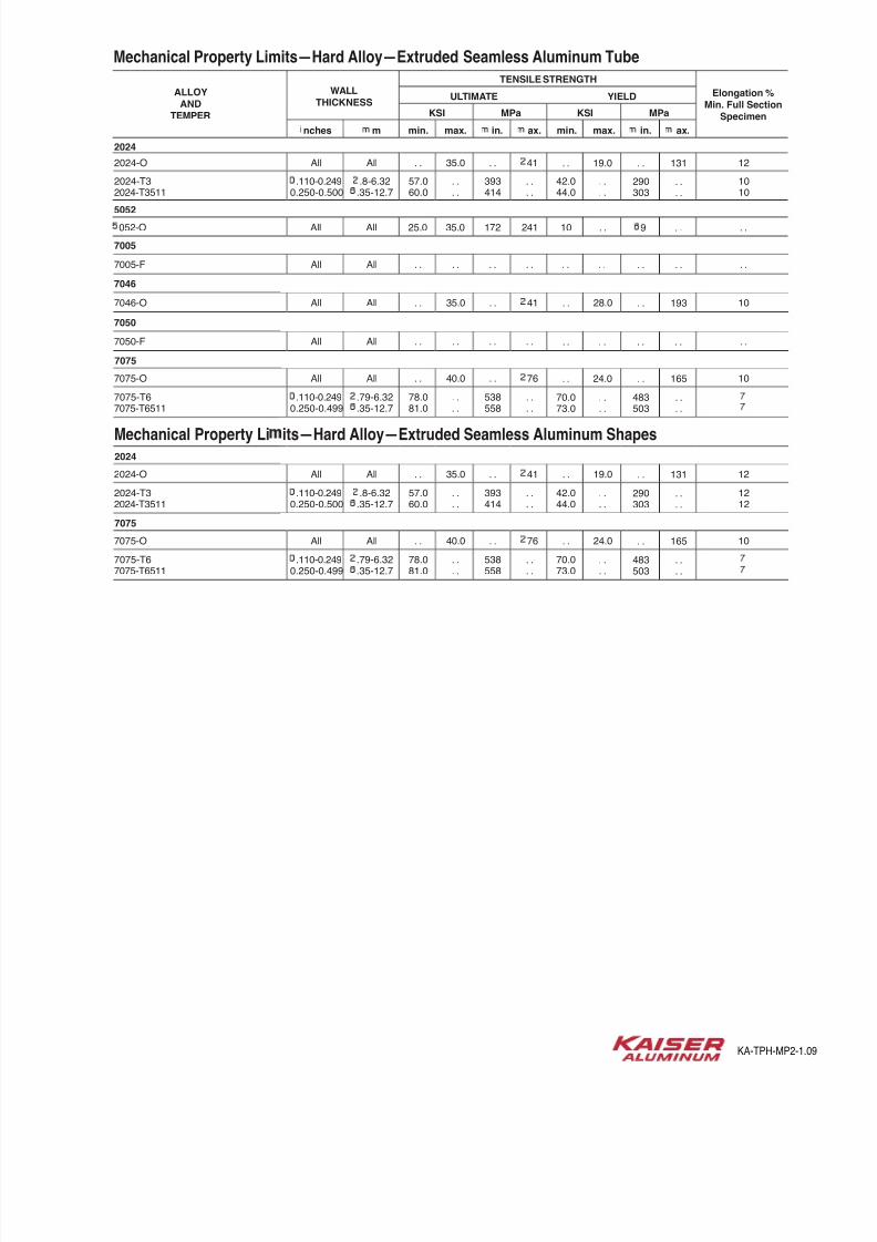
Mechanical Property Limits—Hard Alloy—Extruded Seamless Aluminum Tube
2024
. . 122024-O
ALLOYAND
TEMPER
WALLTHICKNESS
nches m
TENSILE STRENGTH
ULTIMATE YIELD
KSI MPa KSI MPa
min. max. in. ax. min. max. in. ax.
Elongation %Min. Full Section
Specimen
35.0 . . 41 . . 19.0 . . 131All
.110-0.249
0.250-0.500
57.0
60.0
10
10
2024-T3
2024-T3511
. .
. .
393
414
. .
. .
42.0
44.0
. .
. .
290
303
. .
. .
.8-6.32
.35-12.7
All 25.0 . .052-O 35.0 172 241 10 . . 9 . .All
5052
All . . . .7005-F . . . . . . . . . . . . . .All
7005
All . . 107046-O 35.0 . . 41 . . 28.0 . . 193All
7046
All . . . .7050-F . . . . . . . . . . . . . .All
7050
All . . 107075-O 40.0 . . 76 . . 24.0 . . 165All
7075
.110-0.249
0.250-0.499
78.0
81.0
7075-T6
7075-T6511
. .
. .
538
558
. .
. .
70.0
73.0
. .
. .
483
503
. .
. .
.79-6.32
.35-12.7
All . . 122024-O 35.0 . . 41 . . 19.0 . . 131All
2024
.110-0.249
0.250-0.500
57.0
60.0
12
12
2024-T3
2024-T3511
. .
. .
393
414
. .
. .
42.0
44.0
. .
. .
290
303
. .
. .
.8-6.32
.35-12.7
All . . 107075-O 40.0 . . 76 . . 24.0 . . 165All
7075
.110-0.249
0.250-0.499
78.0
81.0
7075-T6
7075-T6511
. .
. .
538
558
. .
. .
70.0
73.0
. .
. .
483
503
. .
. .
.79-6.32
.35-12.7
Mechanical Property Li its—Hard Alloy—Extruded Seamless Aluminum Shapes
KA-TPH-MP2-1.0

8/12/2019 Kaiser Aluminum Hard Alloy Drawn Seamless Tube Capabilities
http://slidepdf.com/reader/full/kaiser-aluminum-hard-alloy-drawn-seamless-tube-capabilities 5/7
ABLE 12.20 Diameter—Drawn Round Tube
TOLERANCEW—in. plus and minus
ALLOWABLE DEVIATION OF MEAN DIAMETERE ALLOWABLE DEVIATION OF DIAMETER AT ANY POINTFROM SPECIFIED DIAMETER (Size) FROM SPECIFIED DIAMETER R
Difference between AA or BB and speci ed diameter
Difference between ½ (AA + BB) NON-ANNEALED ANDand specifi ed diameter NON-HEAT-TREATED
HEAT-TREATED NNEALED
TUBEUBET TUBE
Col. 1 Col. 2 Col. 3 Col. 4 Col. 5
Up thru 0.500 .003 .003 .006 .018 0.501–1.000 .004 .004 .008 .024 1.001–2.000 .005 .005 .010 .030 2.001–3.000 .006 .006 .012 .036 3.001–5.000 .008 .008 .016 .048 5.001–6.000 .010 .010 .020 .060 6.001–8.000 .015 .015 .030 .090 8.001–10.000 .020 .020 .040 .120
10.001–12.000 .025 .025 .050 .150
SPECIFIEDDIAMETER
in.
ABLE 12.21 Width and Depth—Drawn Square, Rectangular, Hexagonal and Octagonal TubeOLERANCEW—in. plus and minus
ALLOWABLE DEVIATION OF WIDTH OR DEPTH ALLOWABLE DEVIATION OF WIDTH OR DEPTHAT CORNERS FROM SPECIFIED WIDTH OR DEPTH NOT AT CORNERS
FROM SPECIFIED WIDTH OR DEPTH U
Difference between AA and speci ed Difference between AA and specifi edwidth or depth width, depth, or distance across fl ats
SQUARE,,
HEXAGONAL, OCTAGONALRECTANGULAR
Col. 1 Col. 2 Col. 3 Col. 4
Up thru 0.500 .003 .0060.501–1.000 .004 .0081.001–2.000 .005 .010
2.001–3.000 .006 .0123.001–5.000 .008 .0165.001–6.000 .010 .020
6.001–8.000 .015 .0308.001–10.000 .020 .040
10.001–12.000 .025 .050
he tolerance for the width is thevalue in Col. 3 for the dimensionqual to the depth, and conversely,ut in no case is the tolerance lesshan at the corners.Y
SPECIFIEDWIDTH
ORDEPTH
in.
When outside diameter, inside diameter, and wall thickness (or their
quivalent dimensions in other than round tube) are all specified, standard
olerances are applicable to any two of these dimensions, but not to all three.
hen both outside and inside diameters or inside diameter and wall thick-
ness are specified, the tolerance applicable to the specified or calculated
.D. dimension shall also apply to the I.D. dimension.
When a dimension tolerance is specified other than as an equal bilateral
olerance, the value of the standard tolerance is that which applies to the
mean of the maximum and minimum dimensions permissible under the
olerance of the dimension under consideration.
Mean diameter is the average of two diameter measurements taken at
right angles to each other at the same longitudinal location on the tube.
R Not applicable to coiled tube or tube having a wall thickness less than
½ percent of the speci ed outside diameter. The tolerance for tube with wall
thickness less than 2½ percent of the speci ed outside diameter is determined
y multiplying the applicable tolerance in columns 3 thru 5 as follows:% to 2½% exclusive—1.5 × tolerance
1½% to 2% exclusive—2.0 × tolerance
1% to 1½% exclusive—3.0 × tolerance
% to 1% exclusive—4.0 × toleranceT For the T8 tempers of 6063 the tolerance in Column 3 apply.Y Example: The width tolerance of 1 × 3 inch rectangular tube is plus and
minus 0.008 inch, and the depth tolerance is plus and minus 0.012 in.U Not applicable to annealed (O temper) tube.
ootnotes or a es . an .
This data reprinted from Aluminum standards and data 2006 with permission from The Aluminum Association, Inc. KA-TPH-AA1-1.0

8/12/2019 Kaiser Aluminum Hard Alloy Drawn Seamless Tube Capabilities
http://slidepdf.com/reader/full/kaiser-aluminum-hard-alloy-drawn-seamless-tube-capabilities 6/7
ABLE 12.22 Diameter—Drawn Oval, Elipticaland Streamline Tube
TOLERANCE Q W—in.
LENGTH OF LENGTH OFMAJOR AXIS, in. MAJOR AXIS, in.
Difference between Difference betweenAA and AA and
speci ed length speci ed length
Col. 1 Col. 2 Col. 3
Up thru 2.500 +.040 −.025 +.025 −.015 2.501–4.250 +.050 −.035 +.035 −.025 4.251–6.000 +.070 −.050 +.055 −.040 6.001–8.000 +.100 −.085 +.080 −.060 8.001–10.000 +.160 −.140 +.115 −.085
EQUIVALENTROUND
DIAMETER T
in.
TABLE 12.23 Corner Radii—Drawn Tube
TOLERANCE W—in.
ALLOWABLE DEVIATION FROMSPECIFIED RADIUS
Difference between radius A andspeci ed radius
Sharp Corners +Q-yr
0.016–0.187 ±Q-yr
0.188 and over ±10%
SPECIFIED U
RADIUS
in.
ABLE 12.24 Wall Thickness—Drawn Round and Other-Than-Round Tube
TOLERANCE Q W—in. plus and minus
ALLOWABLE DEVIATION OF MEAN WALL ALLOWABLE DEVIATION OF WALL THICKNESSTHICKNESS E FROM SPECIFIED AT ANY POINT FROM SPECIFIED WALL THICKNESS
WALL THICKNESS (Eccentricity)
ROUND, NON-HEAT- ROUND, HEAT-TREATABLE ALLOYS ANDTREATABLE ALLOYS Y OTHER THAN ROUND, ALL ALLOYS
Difference between ½(AA+BB) andspeci ed wall thickness
Col. 1 Col. 2 Col. 3 Col. 4
0.010–0.035 .002 .0020.036–0.049 .003 .0030.050–0.083 .004 .0040.084–0.120 .005 .006
0.121–0.203 .006 .0080.204–0.300 .008 .0120.301–0.375 .015 .0200.376–0.500 .020 .030
Plus and minus 10% of specifiedwall thickness, min ±0.003
SPECIFIEDTHICKNESS R
in
When outside diameter, inside diameter, and wall thickness (or their
quivalent dimensions in other-than-round tube) are all specified, standard
tolerances are applicable to any two of these dimensions, but not to all three.
hen both outside and inside diameters or inside diameter and wall thick-
ness are specified, the tolerance applicable to the specified or calculated
.D. dimension shall also apply to the I.D. dimension.
When a dimension tolerance is specified other than as an equal bilateral
tolerance, the value of the standard tolerance is that which applies to the
mean of the maximum and minimum dimensions permissible under the
tolerance for the dimension under consideration.
E The mean wall thickness of round tube is the average of two measure-
ments taken opposite each other. The mean wall thickness of other-than-
round tube is the average of two measurements taken opposite each other
t approximate center line of tube and perpendicular to the longitudinal axis
f the cross section.R When dimensions specified are outside and inside, rather than wall thick-
ness itself, allowable deviation at any point (eccentricity) is plus and minus
10 percent of the mean wall thickness but not less than ±0.003 inch.T Equivalent round diameter is the diameter of the circle having a circumfer-
nce equal to the per imeter of the tube.Y For coiled tube, values in Column 4 apply.U If unspecified, the radius shall be Q-ew in. maximum including tolerances.
Footnotes for Tables 12.22 through 12.24
This data reprinted from Aluminum standards and data 2006 with permission from The Aluminum Association, Inc. KA-TPH-AA2-1.0

8/12/2019 Kaiser Aluminum Hard Alloy Drawn Seamless Tube Capabilities
http://slidepdf.com/reader/full/kaiser-aluminum-hard-alloy-drawn-seamless-tube-capabilities 7/7
TABLE 12.25 Straightness—Drawn Tube
TOLERANCE Q W—in.
ALLOWABLE DEVIATION FROM STRAIGHT
D(max)
IN TOTAL LENGTH OR IN ANYMEASURED SEGMENT OF ONE FT.
OR MORE OF TOTAL LENGTH
Up thru 0.374 .500 × Measured length, ft. 0.375–5.999 .010 × Measured length, ft. 6.000 and over .020 × Measured length, ft.
SPECIFIEDOUTSIDE
DIAMETEROR WIDTH
in.
TABLE 12.26 Twist R—Drawn Tube
TOLERANCE Q W—Degree
ALLOWABLE DEVIATION FROM STRAIGHT
Y (max) in degrees
IN TOTAL LENGTH OR
IN ANY MEASURED MAXIMUM SEGMENT OF ONE FT. OR
FOR TOTAL
MORE OF TOTAL LENGTHLENGTH
Up thru 1.499 1 × Measured length, ft. 7 1.500–2.999 ½ × Measured length, ft. 5 3.000 and over ¼ × Measured length, ft. 3
SPECIFIEDWIDTH
in.
TABLE 12.27 Length—Drawn Tube
TOLERANCE—in. plus except as noted
ALLOWABLE DEVIATION FROM SPECIFIED LENGTH
STRAIGHT COILED
SPECIFIED LENGTH—ft.
Up Over 12 Over 30thru thru thru Over Up thru Over 100 250 500 and12 30 50 50 100 to 250 to 500 over
Up thru 0.249 ¼ E-i ½ . . +5%, –0% ±10% ±15% ±20% 0.250–1.249 Q-i ¼ E-i 1 +5%, –0% ±10% ±15% ±20% 1.250–2.999 Q-i ¼ E-i 1 . . . . . . . . 3.000–7.999 E-qy T-qy U-qy 1 . . . . . . . .
8.000 and over ¼ E-i ½ 1 . . . . . . . .
OR WIDTH
TABLE 12.28 latness (Flat Surfaces)—Other-Than-Round Drawn Tube
TOLERANCE E—in.
ALLOWABLE DEVIATION FROM FLAT
Maximum allowable distance Y
Up thru 0.500 .003 0.501–1.000 .004 1.001–2.000 .005 2.001–3.000 .006
3.001–5.000 .008 5.001–6.000 .010 6.001–8.000 .015 8.001–10.000 .020 10.001–12.000 .025
SPECIFIEDWIDTH OR DEPTH
in.
Q
Tolerance is applicable when weight of tube on flat surface minimizes
deviation.W Not applicable to annealed (O temper) tube.E Not applicable to annealed (O temper) tube, coiled tube, or tube having
a wall thickness less than 0.020 inch or less than 2½% of the equivalen
round diameter. Equivalent round diameter is the diameter of a circle having
a circumferance equal to the perimeter of the tube.R Twist is normally measured by placing the drawn tube on a flat surface
and at any point along its length measuring the maximum distance betwee
the bottom surface of the drawn tube and the flat surface. From this measurement, the actual deviation from straightness of the drawn tube at tha
oint is subtracted. The remainder is the twist. To convert the standard twis
tolerance (degrees) to an equivalent linear value, the sine of the standard
tolerance is multiplied by the width of the surface of the section that is on
the flat surface. The following values are used to convert angular tolerance
to linear deviation:
Maximum allowable
Tolerance, linear deviation
degrees inch per inch of width
¼ 0.004
½ 0.009
1 0.017
1½ 0.026
3 0.052
5 0.087
7 0.122
9 0.156 15 0.259
21 0.358
Footnotes for Tables 12.25 through 12.28
This data reprinted from Aluminum standards and data 2006 with permission from The Aluminum Association, Inc. KA-TPH-AA3-1.0