kapitel 01 faltenbälge 2013 gb 16082013 korr - · pdf fileall dimensions in mm if not...
TRANSCRIPT

Modular concept
Standard Bellows
Bellows
Construction
TK thermal bonded
HF welded
S stitched
L bonded / laminated
Metal frame
Frame of synthetic material
Velcro tape
Snap fastener
Strap retainer
Frame of synthetic material
Metall intemediate frame
Multiple layer foil technique
Panthograph systems
Extensions limiters
Ball bearings
Roller bearings
Guiding rails
Glider profiles
Method of fixing
Stabilisingguides
Gliding guides
02
Servic
e &
Qu
alit
y
08
Sta
nd
ar
d
Bello
ws
18
SA
uM
RA
I
Bello
ws
26
Spec
ial
Bello
ws
32
Ba
ck
wa
ll
System
s
38
Gla
dia
to
r
Steel C
overs
46
Ro
ller
System
s
58
Du
ra
spr
ing
Spir
al S
pr
ing
s
68
Vie
win
g
System
s

All dimensions in mm if not marked otherwise. Errors and omissions excepted.
ELASTIC Bellows
DesignELASTIC Bellows are a series of products with many combi-nations and options. Their basic components, materials, forms,processing methods, and dimensions are easily adaptable. For applications such as elevating platforms, bellows can beproduced with up to 30 square meters. All ELASTIC Bellowsmay be deployed horizontally or vertically. They can be easily attached to the machine with metalframes or Velcro tapes.Efficient glider profiles and roller or ball bearings improvequiet running and also serve to extend life cycles and minimise friction during HSC applications as well.
ELASTIC Bellows are commonly used for protecting machinesand devices against debris and chips. They are also used inmany variations for safety at work. The experience resulting from the production of manythousands of ELASTIC Bellows and their use in workingapplications has been converted directly into product improve-ments, new developments, and enhanced product lifetime.
Constantly growing demands for ever greater machinespeeds and ever lower noise emissions are consistentlyimplemented by our engineers.
Optimal use of spaceMachine size reduced with special materials and space
saving designsComplete systems - bellows integrated in the machine'srear wall covering, complete with guides and mountingdevicesHigh temperature resistant materials up to 600°C forlaser, plasma and welding applicationsSpecial designs with antistatic surfaces for medical technology and clean room conditionsSpecial designs for HSC applicationsImpermeability to coolants
U shape ELASTIC Bellows mounted with metal frame
Bellows for elevating platform
Glider profilesTypes
09
18
Sta
nd
ar
d
Bello
ws
SA
uM
RA
I
Bello
ws
02
Servic
e &
Qu
alit
y
26
Spec
ial
Bello
ws
38
Gla
dia
to
r
Steel C
overs
46
Ro
ller
System
s
58
Du
ra
spr
ing
Spir
al S
pr
ing
s
68
Vie
win
g
System
s
32
Ba
ck
wa
ll
System
s

Order and request forms available at: www.hema-schutz.de
ELASTIC bellows are available in the following versionsdepending on how their frames are permanently joined to theouter fold material:
thermal bonded versionHF welded versionsewn version
Thermal bonded version Under the action of heat and a specially developed flux per-manent bonding is achieved between the inner PVC frameand the outer fold material. Thermal bonded ELASTIC Bellows are maintenance free,water and dust proof as well as oil resistant and, to a certainextent, acid resistant.
HF welded versionThis type is used particularly for the production of large,shutter type ELASTIC Bellows. High frequency welding is used to join the PVC frames withthe outer bellow material for a perfect shape and a regularoverall appearance.
Sewn versionThe sewn version consists primarily of high temperaturematerials. Strong fabrics therefore assure a long lasting solu-tion even under extreme loads.
Mounting ELASTIC Bellows can be easily mounted on machines anddevices with components such as:
frames of metal or synthetic material attached to bothends and designed to customer specificationsVelcro tape, easy and fast, maintenance friendlyclip fasteners combined with metal frames
During high starting accelerations extension limiters help toreduce the load on the first folds, even out the extension, andstabilise travelling.
MaterialStandard materials are black, but also signal colours such asyellow or white materials for medical applications are available.The material is selected from a large range of products tomatch the intended use of the ELASTIC Bellows. Also self extinguishing heat resisting materials under the UL 94 standard are available.
Design of ELASTIC BellowsThe essential component of the ELASTIC Bellows is a stabili-sing PVC frame inside every fold that lends the ELASTICBellows high dimensional stability. Reversion to the originalshape is therefore assured after direct impacts. Beside PVC frames PP and Polyamide can be offered as analternative material for the support frames.
ELASTIC Bellows
Bellows construction with stabilising PVC frame
U shape Bellows with stabilising PVC frame
Roller bearing
FAZ
FB
FZD
02
Servic
e &
Qu
alit
y
10
Sta
nd
ar
d
Bello
ws
18
SA
uM
RA
I
Bello
ws
26
Spec
ial
Bello
ws
32
Ba
ck
wa
ll
System
s
38
Gla
dia
to
r
Steel C
overs
46
Ro
ller
System
s
58
Du
ra
spr
ing
Spir
al S
pr
ing
s
68
Vie
win
g
System
s
Standard Bellows

All dimensions in mm if not marked otherwise. Errors and omissions excepted.
ELASTIC Bellows
FB Width of the foldFZ Number of foldsFZD Compression per foldFAZ Extension per foldBE Width of the terminal fixtureAZ Maximum extensionZD Minimum compression
Formulae for calculationZD AZ-Hub
FZ AZFAZ
ZD (AZ x FZD) + BEFAZ
AZ (ZD - BE) x FAZFZD
Legend and formulae for calculation
15 22 3 - 5
17,5 24 3 - 5
20 30 3 - 5
25 38 3 - 5
30 48 3 - 5
35 55 3 - 5
40 65 3 - 5
45 75 3 - 550 85 3 - 5
* depending on material
FB (mm) FAZ (mm) FZD*( mm)
Rear view of complete solution, ELASTIC Bellows used for X axis
11
18
Sta
nd
ar
d
Bello
ws
SA
uM
RA
I
Bello
ws
02
Servic
e &
Qu
alit
y
26
Spec
ial
Bello
ws
38
Gla
dia
to
r
Steel C
overs
46
Ro
ller
System
s
58
Du
ra
spr
ing
Spir
al S
pr
ing
s
68
Vie
win
g
System
s
32
Ba
ck
wa
ll
System
s
exterior »half« fold»half« fold
End flanges can also be mounted from the outside
exterior »full« fold»full« fold
aEnd flanges can be mounted only from the inside
Mounted with velcro tape, both sides full fold
Mounting with velcro tape, one side half, one side full fold
Mounted with clip fasteners, both sides full fold
Mounted with clip fasteners, one side half, one side full fold

Order and request forms available at: www.hema-schutz.de
LAMINAT Bellows
LAMINAT Bellows are characterized by several layers of foilbonded together. The LAMINAT bellows are used whereflexible designs and inherent rigidity are important.
ApplicationLAMINAT Bellows are nowadays deployed in spindle-type lifting gear, for cameras, measuring and music instruments aswell as for medicine and food technologies. They are used toprotect columns, spindles and shafts.
All LAMINAT Bellows can be used vertically or horizontally,including hybrid forms. They allow smooth and very quietrunning properties. The surface structure and the regularity of contours presentan appealing overall appearance.
LAMINAT Bellows are not suited to applications with hightemperatures and humidity. If these criteria should berelevant, models from our other lines may be considered,such as Rubber Disk Bellows or Fabric Bellows (see SpecialBellows section).
MaterialLAMINAT Bellows can be adapted through the choice ofbasic components, materials, shape, colours, and dimensions.The basic design concept of the LAMINAT Bellows is basedon a two-component material. A manufacturing technique developed to perfectioncombines the outer material requested by the customer withthe appropriate interior material selected by the HEMAdesigner. For additional stability PVC or metal frames can beadded.
MaintenanceA further benefit of these bellows comes in the form of theirsegmented design. Damaged parts of the LAMINAT Bellowscan be easily replaced, reducing significantly the costs formaintenance.
DesignLike the ELASTIC Bellows LAMINAT Bellows can also be designed and produced in a variety of forms. LAMINAT Bellows are primarily used to cover and protectcolumns and spindles. Rectangular, hexagonal, octagonaland twelve-sided sections are available as well as roof andinclined shapes and Venetian blind style standards.
LAMINAT Bellows with octagon section and strap retainer
LAMINAT Bellows with intermediate frames
Perfect surface of LAMINAT Bellows for medical devices
02
Servic
e &
Qu
alit
y
12
Sta
nd
ar
d
Bello
ws
18
SA
uM
RA
I
Bello
ws
26
Spec
ial
Bello
ws
32
Ba
ck
wa
ll
System
s
38
Gla
dia
to
r
Steel C
overs
46
Ro
ller
System
s
58
Du
ra
spr
ing
Spir
al S
pr
ing
s
68
Vie
win
g
System
s
Standard Bellows

All dimensions in mm if not marked otherwise. Errors and omissions excepted.
CharacteristicThe stiffness of LAMINAT Bellows (standard designs) can beenhanced with an optional PVC frame or wire hoop in everysecond or third fold.
Furthermore they can be supported on special gliders orroller systems, recommend at speeds higher than 30 m/min.On the polygon sections, spacers and circular guide/supportsystems ensure the optimum gliding efficiency on columns,spindles and shafts. Also extension limiters assure consistent extension after highacceleration impacts.
MountingLAMINAT Bellows can be easily mounted with metal endframes, clip fasteners, velcro tapes, or sleeves with strapretainer (for polygonal sections only). Closed designs require adequate ventilation. We offeroptional punching with or without filter.
LAMINAT Bellows are available as split designs as well. The split type facilitates bellow replacement and mainte-nance, and so is perfect as a retrofit on machines. The bellowscan afterwards be closed with adhesive tape, Velcro tape orbonding. The higher compression of these types must betaken into consideration.
Polygonal section with support elementsThis sectional view shows an example of a design solution forhorizontal applications. Sub frames with guides or guide rings are used here to support the shaft or spindle.These additional guiding elements ensure that the LAMINATbellows run smoothly and with less friction
LAMINAT Bellows
Sectional view of bellows with support elements
Split version for fast mounting or retrofitting
LAMINAT Bellows, view of interior
U shape
Hexagonal shape Octagon shapeRectangular shape
Venetian Blind shape
Range of available shapes
Inclined shapeRoof shape
U shape with return Rectangular shape
13
18
Sta
nd
ar
d
Bello
ws
SA
uM
RA
I
Bello
ws
02
Servic
e &
Qu
alit
y
26
Spec
ial
Bello
ws
38
Gla
dia
to
r
Steel C
overs
46
Ro
ller
System
s
58
Du
ra
spr
ing
Spir
al S
pr
ing
s
68
Vie
win
g
System
s
32
Ba
ck
wa
ll
System
s
Slee
ve
D
Inne
r gu
ides
AZ

Order and request forms available at: www.hema-schutz.de
7,5 8 3
10 13 3
12.5 15 3
15 20 3
17.5 23 3
20 25 3
25 30 3.5
30 35 3.5
35 40 4
40 45 4
45 50 4
50 55 4
FB FAZ FZD
FB Width of the foldFZD Compression per fold, depending on materialFAZ Extension per fold
Legend
Alternating folds
Alternating folds
7,5 9 3
10 15 3
12.5 18 3
15 20 3
17.5 25 3
20 30 3
25 37 3.5
30 45 3.5
35 55 4
40 60 4
45 65 4
50 70 4
FB FAZ FZD
Standard folds
LAMINAT Bellows
FB FB
02
Servic
e &
Qu
alit
y
14
Sta
nd
ar
d
Bello
ws
18
SA
uM
RA
I
Bello
ws
26
Spec
ial
Bello
ws
32
Ba
ck
wa
ll
System
s
38
Gla
dia
to
r
Steel C
overs
46
Ro
ller
System
s
58
Du
ra
spr
ing
Spir
al S
pr
ing
s
68
Vie
win
g
System
s
Standard Bellows

All dimensions in mm if not marked otherwise. Errors and omissions excepted.
The circular-stitched bellows consist of punched disks stitchedinside and outside. Stitching achieves particularly good shape stability and hightransverse stiffness.
MaterialStandard applications require material GN 807, and hightemperature applications aluminium/glass fibre.Circular-stitched bellows are extremely resistant and caneven withstand impact from sharp edged chips, also in thesmaller versions. They are suitable only to a limited extent asprotection against liquids and oils.
Mounting positionCircular-stitched bellows can be used horizontally or verti-cally. Additional support and guide rings made of syntheticsassure a uniform distance from the spindle and so increaseoperating life. When with large extensions the stability of the bellows canbe increased when a wire ring is installed in every fold.
Extension = (Stroke / FStroke) x FAZ + 5
AD Outside diameterFB Fold widthID Inside diameterFAZ Fold extensionFZD Fold compressionFStroke Stroke per foldSD Diameter of spindle
Design and Legend
HEMA Type AD ID FB FAZ FZD FStroke
Circular-Stitched Bellows
RF 50 52 25 12.5 10 2.5 7.5
RF 72 72 33 19.5 18 2.5 15.5
RF 85 85 45 20 18 2.5 15.5
RF 95 95 53 21 18 2.5 15.5
RF 100 100 63 18.5 18 2.5 15.5
RF 120 120 82 19 18 2.5 15.5
RF 122 122 76 23 15 2.5 12.5
RF 130 130 90 20 18 2.5 15.5
RF 135 135 85 25 15 2.5 12.5
RF 140 140 100 19 18 2.5 15.5
RF 145/1 145 93 26 15 2.5 12.5
RF 145/2 145 105 20 18 2.5 15.5
RF 150 150 110 20 18 2.5 15.5
RF 160 160 112 24 18 2.5 15.5
RF 170 170 125 22.5 18 2.5 15.5
RF 180/1 180 132 24 20 2.5 17.5
RF 180/2 180 141 19.5 18 2.5 15.5
RF 190 190 150 20 18 2.5 15.5
RF 200 200 152 24 18 2.5 15.5
RF 220 220 170 25 18 2.5 15.5
RF 235 235 190 22.5 18 2.5 15.5
RF 245 245 200 22.5 20 2.5 17.5
RF 260 260 202 29 18 2.5 15.5
RF 266 266 216 25 20 2.5 17.5
RF 300 300 250 25 18 2.5 15.5
RF 365 365 320 22.5 18 2.5 15.5
RF 400 400 340 30 20 2.5 17.5
Circular stitched bellows
The usual connecting and mounting elements are metalframes, but sleeves are an alternative.
Design informationThe correct bellow diameter should be about 10 mm largerthan the part they are to protect. Use the following formula formeasurements.
Sectional view: Circular stitched bellows
15
18
Sta
nd
ar
d
Bello
ws
SA
uM
RA
I
Bello
ws
02
Servic
e &
Qu
alit
y
26
Spec
ial
Bello
ws
38
Gla
dia
to
r
Steel C
overs
46
Ro
ller
System
s
58
Du
ra
spr
ing
Spir
al S
pr
ing
s
68
Vie
win
g
System
s
32
Ba
ck
wa
ll
System
s
AZ
HubZD
ADIDSD
Order and request forms available at: www.hema-schutz.de
High temperature resistance of bellow materialNo outgassing of materialsGas-tight for minimised flushing gas losses Superior clean state during production and shipment
Construction For better stability the bellows used for jet cutting machinesare fitted with stabilizing synthetic material frames.These frames are customized to each guidance type, e.g guiding bars. Normally these bellows are mounted with metalend frames. Especially important is a separate guiding system that keepsthe bellows material intact.
Modern jet cutting machines (with lasers, plasma or water)are fitted with bellows to protect the jet channel and themechanical components such as spindles and guides.
These types of bellows require a high level of tightness andlong life.Bellows for jet cutting machines are primarily made of selfextinguishing materials such as Preotex.The materials selected have been extensively tested withvarious impact cycles.
At all stages from production to packaging and shipment ourbellows are maintained in a particularly clean state and freeof dust, e.g. with special packing.
Bellows for jet cutting machines
Guided bellows for laser cutting
Bellows in operation
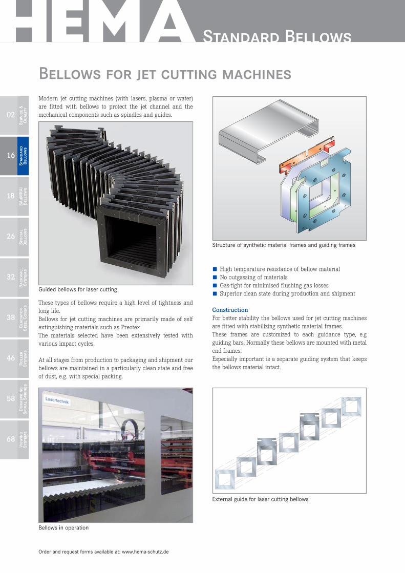
Structure of synthetic material frames and guiding frames
External guide for laser cutting bellows
02
Servic
e &
Qu
alit
y
16
Sta
nd
ar
d
Bello
ws
18
SA
uM
RA
I
Bello
ws
26
Spec
ial
Bello
ws
32
Ba
ck
wa
ll
System
s
38
Gla
dia
to
r
Steel C
overs
46
Ro
ller
System
s
58
Du
ra
spr
ing
Spir
al S
pr
ing
s
68
Vie
win
g
System
s
Standard Bellows

All dimensions in mm if not marked otherwise. Errors and omissions excepted.
Linear drives can be either retrofitted by the customer or fit-ted with bellows before they leave the factory. HEMA has specialised in this field and offers bellows tailoredto the leading international manufacturers, e.g. INA, NSK,Schneeberger, Bosch-Rexroth, THK or NSK.
On the basis of precise type denominations the bellows andtheir guiding components can be manufactured correctly tosize.
MaterialStandard applications require PU coated materials, but heatresistant and self extinguishing materials are also available. For the best services and immediate replacements thesebellows are also available as »endless versions« with 200 ormore folds in total. The required dimensions can easily be configured by the customer.
Bellows for Linear Guides
FB Fold widthFAZ Extension per foldfba Width of guiding wayAH Exterior heightX Interior heightS Play
Legend
Example application
Diagram of an application
17
18
Sta
nd
ar
d
Bello
ws
SA
uM
RA
I
Bello
ws
02
Servic
e &
Qu
alit
y
26
Spec
ial
Bello
ws
38
Gla
dia
to
r
Steel C
overs
46
Ro
ller
System
s
58
Du
ra
spr
ing
Spir
al S
pr
ing
s
68
Vie
win
g
System
s
32
Ba
ck
wa
ll
System
s
design length
cut along the lines
fold in
and glue
cut herecut here
2
4