karki, sabin; ala-laurinaho, juha; karttunen, aki; viikari
TRANSCRIPT
This is an electronic reprint of the original article.This reprint may differ from the original in pagination and typographic detail.
Powered by TCPDF (www.tcpdf.org)
This material is protected by copyright and other intellectual property rights, and duplication or sale of all or part of any of the repository collections is not permitted, except that material may be duplicated by you for your research use or educational purposes in electronic or print form. You must obtain permission for any other use. Electronic or print copies may not be offered, whether for sale or otherwise to anyone who is not an authorised user.
Karki, Sabin; Ala-Laurinaho, Juha; Karttunen, Aki; Viikari, VilleIntegrated Lens Antennas for E-band
Published in:Proceedings of the 48th European Microwave Conference
DOI:10.23919/EuMC.2018.8541385
Published: 01/01/2018
Document VersionPeer reviewed version
Please cite the original version:Karki, S., Ala-Laurinaho, J., Karttunen, A., & Viikari, V. (2018). Integrated Lens Antennas for E-band. InProceedings of the 48th European Microwave Conference (pp. 1151-1154). IEEE.https://doi.org/10.23919/EuMC.2018.8541385
Integrated Lens Antennas for E-bandSabin Kumar Karki#1, Juha Ala-Laurinaho#2, Aki Karttunen#3 Ville Viikari#4
#Dept. of Electronics and Nanoengineering, Aalto University, [email protected], [email protected], [email protected], [email protected]
Abstract — This work evaluates the performance of two ILAwith different dielectric materials. Two elliptical ILAs of 32mm radius are designed using Rexolite ( εr= 2.53 and tanδ =0.0013) and PREPERM® L450 (εr = 5.01 and tanδ = 0.0046)materials. The gain and beam-steering properties of these ILAswere thoroughly investigated using raytracing simulations andmeasurements at E-band. Despite the higher loss tangent, theILA with L450 material gives 29.3 dBi gain compared to 28.7dBi of Rexolite material at 73 GHz. The measured gain scan lossfor steering angle of the 24° beam is 4.3 dB and 4.9 dB for thePreperm-ILA and Rexolite-ILA, respectively. Additionally, thework focuses on the dielectric property characterization of theL450 material at millimeter wave frequencies.
Keywords — millimeter waves, integrated lens antenna,dielectric properties.
I. INTRODUCTION
The next generation of cellular communication system,5G, is moving towards millimeter-wave frequencies. Although,specific frequencies have not been allocated yet, the potentialcandidates include 26-30 GHz, 37-42 GHz and E-band i.e.,71-76/81-86 GHz [1], [2]. Millimeter-wave frequencies havehigh propagation and antenna losses and therefore high gainantennas are desired. Additionally, the antennas are desired tobe compact for practical implementation.
Although bulky in size, an integrated lens antenna (ILA)with beam-focusing and steering ability has been a popularchoice in the field of telecommunication, radar and imaging[3], [4], [5]. The size and shape of an ILA is dependent on thegain requirement and dielectric properties of the material used.In [6], permittivity between 3 - 5 is recommended for optimumgain performance. With higher permittivity, the ILA becomesmore compact and the spillover loss reduces. However, thehigher permittivity materials in comparison to low permittivitymaterials have the higher loss tangent. This feature causes anincreases in dielectric loss for high permittivity materials. Inpractice, materials with low permittivity i.e., 2-3, and lowerloss tangent are used in an ILA design which accounts for thebulkiness of the ILA [6], [7], [8].
Therefore, this study investigates the possibility of usingthe relatively high permittivity materials like PREPERM®
L450 in the ILA design. Additionally, the dielectric propertiesof L450 material is characterized at E-band. Then, thePreperm-ILA and Rexolite-ILA with the same diameter aredesigned and simulated. The simulated and measured gainperformance of the Preperm-ILA is compared with thetraditional Rexolite-ILA to evaluate its feasibility.
The paper is organized as follows. In Section 2, an ILAcharacteristics is studied and the dielectric properties of the
L450 material is estimated. The designs of the two ILAs andtheir simulation results are presented in Section 3. Section4 presents the measurement results and its analysis. Finally,Section 5 presents conclusions.
II. ILA CHARACTERISTICS AND L450 CHARACTERIZATION
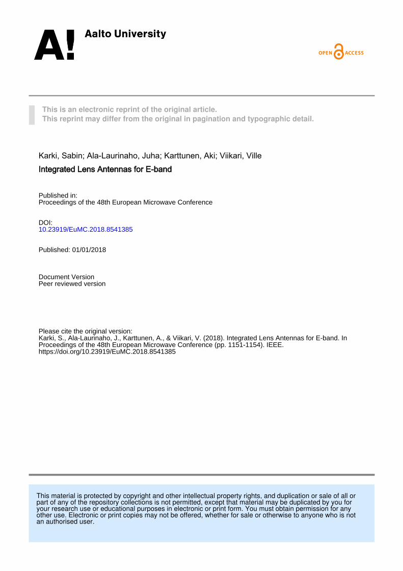
The basic properties of an ILA are well described in[9] and [10]. Furthermore, the design guidelines of an ILAhave been presented in [11]. Based on these guidelines, theheight and losses variation of a 120-mm ILA with varyingpermittivity (constant tanδ = 0.0006) is studied, as shownin Fig. 1. For the given tanδ, the dielectric and reflectionlosses increase marginally with respect to permittivity. Thematerial permittivity is inversely proportional to the heightof an ILA. With increasing permittivity, the height of anILA decreases and consequently the spillover loss decreases.Beyond permittivity 5, the decrease in spillover loss is minimaland is neutralized by the increase in the reflection lossand dielectric loss. Hence, the overall loss saturates, andconsequently, the gain saturates. Although the tanδ increaseswith permittivity, in this simulation study tanδ is constant.
Fig. 1. Variation of losses and height of the 120-mm ILA with loss tangenttanδ = 0.0006.
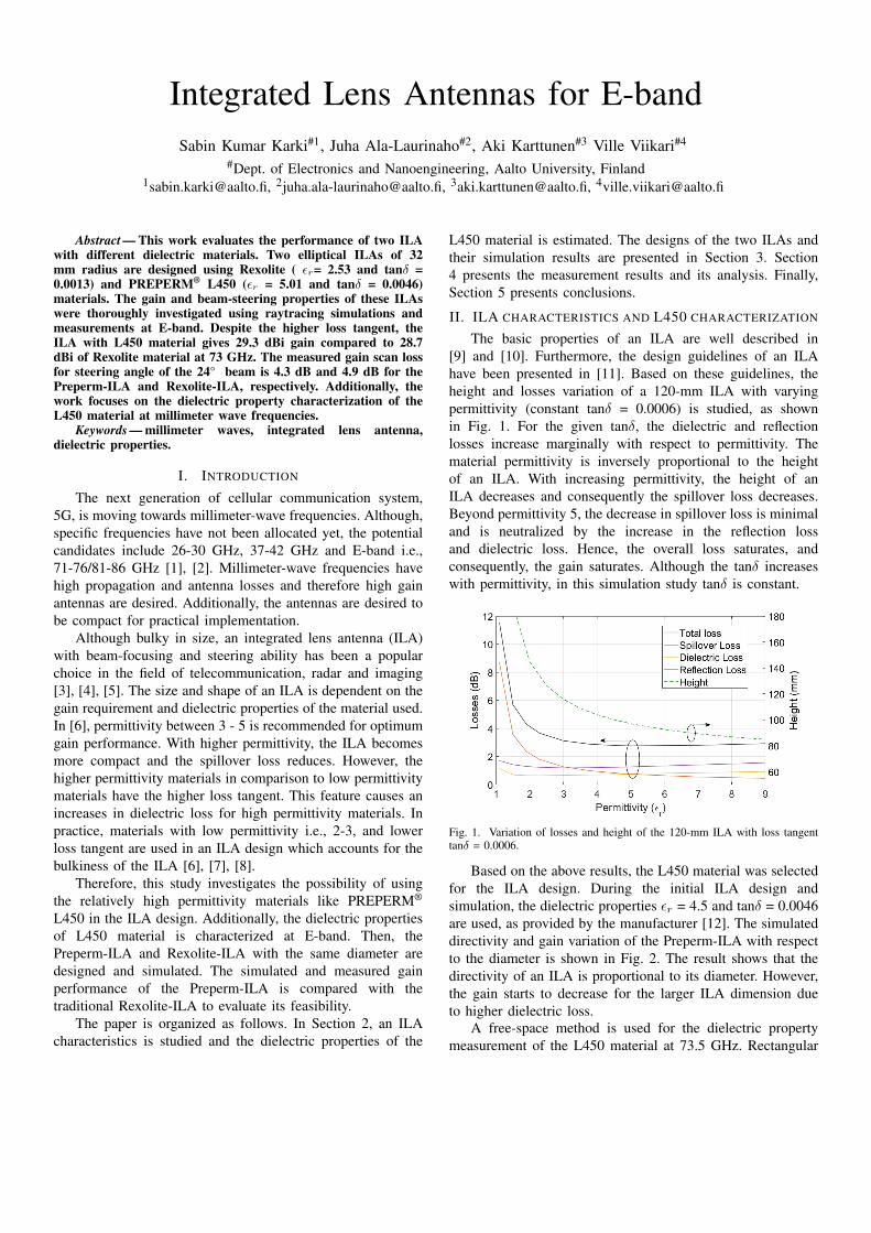
Based on the above results, the L450 material was selectedfor the ILA design. During the initial ILA design andsimulation, the dielectric properties εr = 4.5 and tanδ = 0.0046are used, as provided by the manufacturer [12]. The simulateddirectivity and gain variation of the Preperm-ILA with respectto the diameter is shown in Fig. 2. The result shows that thedirectivity of an ILA is proportional to its diameter. However,the gain starts to decrease for the larger ILA dimension dueto higher dielectric loss.
A free-space method is used for the dielectric propertymeasurement of the L450 material at 73.5 GHz. Rectangular
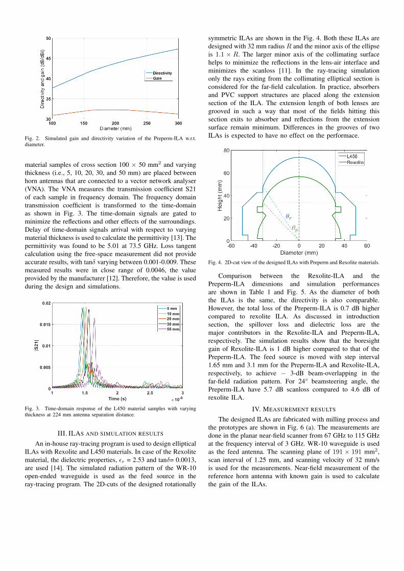
Fig. 2. Simulated gain and directivity variation of the Preperm-ILA w.r.t.diameter.
material samples of cross section 100 × 50 mm2 and varyingthickness (i.e., 5, 10, 20, 30, and 50 mm) are placed betweenhorn antennas that are connected to a vector network analyser(VNA). The VNA measures the transmission coefficient S21of each sample in frequency domain. The frequency domaintransmission coefficient is transformed to the time-domainas shown in Fig. 3. The time-domain signals are gated tominimize the reflections and other effects of the surroundings.Delay of time-domain signals arrival with respect to varyingmaterial thickness is used to calculate the permittivity [13]. Thepermittivity was found to be 5.01 at 73.5 GHz. Loss tangentcalculation using the free-space measurement did not provideaccurate results, with tanδ varying between 0.001-0.009. Thesemeasured results were in close range of 0.0046, the valueprovided by the manufacturer [12]. Therefore, the value is usedduring the design and simulations.
Fig. 3. Time-domain response of the L450 material samples with varyingthickness at 224 mm antenna separation distance.
III. ILAS AND SIMULATION RESULTS
An in-house ray-tracing program is used to design ellipticalILAs with Rexolite and L450 materials. In case of the Rexolitematerial, the dielectric properties, εr = 2.53 and tanδ= 0.0013,are used [14]. The simulated radiation pattern of the WR-10open-ended waveguide is used as the feed source in theray-tracing program. The 2D-cuts of the designed rotationally
symmetric ILAs are shown in the Fig. 4. Both these ILAs aredesigned with 32 mm radius R and the minor axis of the ellipseis 1.1 × R. The larger minor axis of the collimating surfacehelps to minimize the reflections in the lens-air interface andminimizes the scanloss [11]. In the ray-tracing simulationonly the rays exiting from the collimating elliptical section isconsidered for the far-field calculation. In practice, absorbersand PVC support structures are placed along the extensionsection of the ILA. The extension length of both lenses aregrooved in such a way that most of the fields hitting thissection exits to absorber and reflections from the extensionsurface remain minimum. Differences in the grooves of twoILAs is expected to have no effect on the performace.
Fig. 4. 2D-cut view of the designed ILAs with Preperm and Rexolite materials.
Comparison between the Rexolite-ILA and thePreperm-ILA dimesnions and simulation performancesare shown in Table 1 and Fig. 5. As the diameter of boththe ILAs is the same, the directivity is also comparable.However, the total loss of the Preperm-ILA is 0.7 dB highercompared to rexolite ILA. As discussed in introductionsection, the spillover loss and dielectric loss are themajor contributors in the Rexolite-ILA and Preperm-ILA,respectively. The simulation results show that the boresightgain of Rexolite-ILA is 1 dB higher compared to that of thePreperm-ILA. The feed source is moved with step interval1.65 mm and 3.1 mm for the Preperm-ILA and Rexolite-ILA,respectively, to achieve − 3-dB beam-overlapping in thefar-field radiation pattern. For 24° beamsteering angle, thePreperm-ILA have 5.7 dB scanloss compared to 4.6 dB ofrexolite ILA.
IV. MEASUREMENT RESULTS
The designed ILAs are fabricated with milling process andthe prototypes are shown in Fig. 6 (a). The measurements aredone in the planar near-field scanner from 67 GHz to 115 GHzat the frequency interval of 3 GHz. WR-10 waveguide is usedas the feed antenna. The scanning plane of 191 × 191 mm2,scan interval of 1.25 mm, and scanning velocity of 32 mm/sis used for the measurements. Near-field measurement of thereference horn antenna with known gain is used to calculatethe gain of the ILAs.
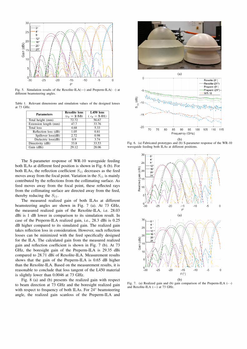
Fig. 5. Simulation results of the Rexolite-ILA(—) and Preperm-ILA(- -) atdifferent beamsteering angles.
Table 1. Relevant dimensions and simulation values of the designed lensesat 73 GHz.
Parameters Rexolite lens(εr = 2.53)
L450 lens( εr = 5.01)
Total height (mm) 72.72 56.67Extension length (mm) 47.7 33.76Total loss 4.68 5.33
Reflection loss (dB) 1.05 0.81Spillover loss(dB) 2.72 0.98
Dielectric loss(dB) 0.9 3.74Directivity (dB) 33.8 33.53Gain (dBi) 29.12 28.06
The S-parameter response of WR-10 waveguide feedingboth ILAs at different feed position is shown in Fig. 6 (b). Forboth ILAs, the reflection coefficient S11 decreases as the feedmoves away from the focal point. Variation in the S11 is mainlycontributed by the reflections from the collimating surface. Asfeed moves away from the focal point, these reflected raysfrom the collimating surface are directed away from the feed,thereby reducing the S11.
The measured realized gain of both ILAs at differentbeamsteering angles are shown in Fig. 7 (a). At 73 GHz,the measured realized gain of the Rexolite-ILA, i.e. 28.03dBi is 1 dB lower in comparison to its simulation result. Incase of the Preperm-ILA realized gain, i.e., 28.3 dBi is 0.25dB higher compared to its simulated gain. The realized gaintakes reflection loss in consideration. However, such reflectionlosses can be minimized with the feed specifically designedfor the ILA. The calculated gain from the measured realizedgain and reflection coefficient is shown in Fig. 7 (b). At 73GHz, the boresight gain of the Preperm-ILA is 29.35 dBicompared to 28.71 dBi of Rexolite-ILA. Measurement resultsshows that the gain of the Preperm-ILA is 0.65 dB higherthan the Rexolite-ILA. Based on the measurement results, it isreasonable to conclude that loss tangent of the L450 materialis slightly lower than 0.0046 at 73 GHz.
Fig. 8 (a) and (b) presents the realized gain with respectto beam direction at 73 GHz and the boresight realized gainwith respect to frequency of both ILAs. For 24° beamsteeringangle, the realized gain scanloss of the Preperm-ILA and
(a)
(b)Fig. 6. (a) Fabricated prototypes and (b) S-parameter response of the WR-10waveguide feeding both ILAs at different positions.
(a)
(b)Fig. 7. (a) Realized gain and (b) gain comparison of the Preperm-ILA (- -)and Rexolite-ILA (—) at 73 GHz.
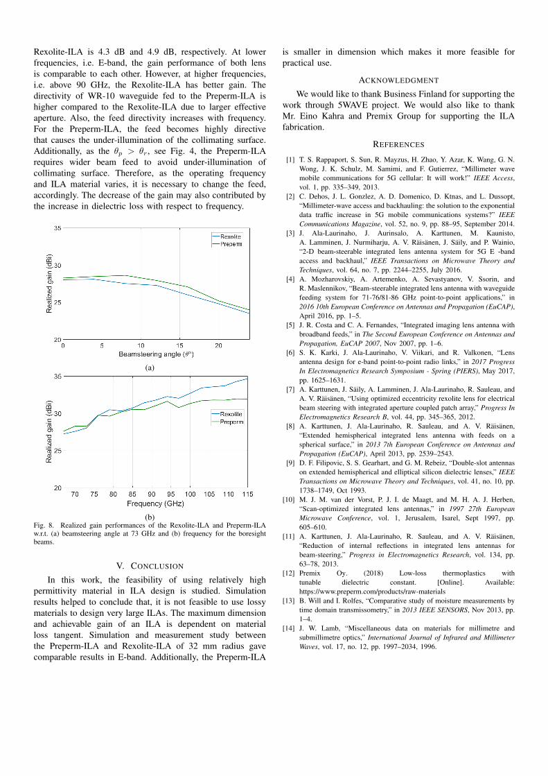
Rexolite-ILA is 4.3 dB and 4.9 dB, respectively. At lowerfrequencies, i.e. E-band, the gain performance of both lensis comparable to each other. However, at higher frequencies,i.e. above 90 GHz, the Rexolite-ILA has better gain. Thedirectivity of WR-10 waveguide fed to the Preperm-ILA ishigher compared to the Rexolite-ILA due to larger effectiveaperture. Also, the feed directivity increases with frequency.For the Preperm-ILA, the feed becomes highly directivethat causes the under-illumination of the collimating surface.Additionally, as the θp > θr, see Fig. 4, the Preperm-ILArequires wider beam feed to avoid under-illumination ofcollimating surface. Therefore, as the operating frequencyand ILA material varies, it is necessary to change the feed,accordingly. The decrease of the gain may also contributed bythe increase in dielectric loss with respect to frequency.
(a)
(b)Fig. 8. Realized gain performances of the Rexolite-ILA and Preperm-ILAw.r.t. (a) beamsteering angle at 73 GHz and (b) frequency for the boresightbeams.
V. CONCLUSION
In this work, the feasibility of using relatively highpermittivity material in ILA design is studied. Simulationresults helped to conclude that, it is not feasible to use lossymaterials to design very large ILAs. The maximum dimensionand achievable gain of an ILA is dependent on materialloss tangent. Simulation and measurement study betweenthe Preperm-ILA and Rexolite-ILA of 32 mm radius gavecomparable results in E-band. Additionally, the Preperm-ILA
is smaller in dimension which makes it more feasible forpractical use.
ACKNOWLEDGMENT
We would like to thank Business Finland for supporting thework through 5WAVE project. We would also like to thankMr. Eino Kahra and Premix Group for supporting the ILAfabrication.
REFERENCES
[1] T. S. Rappaport, S. Sun, R. Mayzus, H. Zhao, Y. Azar, K. Wang, G. N.Wong, J. K. Schulz, M. Samimi, and F. Gutierrez, “Millimeter wavemobile communications for 5G cellular: It will work!” IEEE Access,vol. 1, pp. 335–349, 2013.
[2] C. Dehos, J. L. Gonzlez, A. D. Domenico, D. Ktnas, and L. Dussopt,“Millimeter-wave access and backhauling: the solution to the exponentialdata traffic increase in 5G mobile communications systems?” IEEECommunications Magazine, vol. 52, no. 9, pp. 88–95, September 2014.
[3] J. Ala-Laurinaho, J. Aurinsalo, A. Karttunen, M. Kaunisto,A. Lamminen, J. Nurmiharju, A. V. Raisanen, J. Saily, and P. Wainio,“2-D beam-steerable integrated lens antenna system for 5G E -bandaccess and backhaul,” IEEE Transactions on Microwave Theory andTechniques, vol. 64, no. 7, pp. 2244–2255, July 2016.
[4] A. Mozharovskiy, A. Artemenko, A. Sevastyanov, V. Ssorin, andR. Maslennikov, “Beam-steerable integrated lens antenna with waveguidefeeding system for 71-76/81-86 GHz point-to-point applications,” in2016 10th European Conference on Antennas and Propagation (EuCAP),April 2016, pp. 1–5.
[5] J. R. Costa and C. A. Fernandes, “Integrated imaging lens antenna withbroadband feeds,” in The Second European Conference on Antennas andPropagation, EuCAP 2007, Nov 2007, pp. 1–6.
[6] S. K. Karki, J. Ala-Laurinaho, V. Viikari, and R. Valkonen, “Lensantenna design for e-band point-to-point radio links,” in 2017 ProgressIn Electromagnetics Research Symposium - Spring (PIERS), May 2017,pp. 1625–1631.
[7] A. Karttunen, J. Saily, A. Lamminen, J. Ala-Laurinaho, R. Sauleau, andA. V. Raisanen, “Using optimized eccentricity rexolite lens for electricalbeam steering with integrated aperture coupled patch array,” Progress InElectromagnetics Research B, vol. 44, pp. 345–365, 2012.
[8] A. Karttunen, J. Ala-Laurinaho, R. Sauleau, and A. V. Raisanen,“Extended hemispherical integrated lens antenna with feeds on aspherical surface,” in 2013 7th European Conference on Antennas andPropagation (EuCAP), April 2013, pp. 2539–2543.
[9] D. F. Filipovic, S. S. Gearhart, and G. M. Rebeiz, “Double-slot antennason extended hemispherical and elliptical silicon dielectric lenses,” IEEETransactions on Microwave Theory and Techniques, vol. 41, no. 10, pp.1738–1749, Oct 1993.
[10] M. J. M. van der Vorst, P. J. I. de Maagt, and M. H. A. J. Herben,“Scan-optimized integrated lens antennas,” in 1997 27th EuropeanMicrowave Conference, vol. 1, Jerusalem, Isarel, Sept 1997, pp.605–610.
[11] A. Karttunen, J. Ala-Laurinaho, R. Sauleau, and A. V. Raisanen,“Reduction of internal reflections in integrated lens antennas forbeam-steering,” Progress in Electromagnetics Research, vol. 134, pp.63–78, 2013.
[12] Premix Oy. (2018) Low-loss thermoplastics withtunable dielectric constant. [Online]. Available:https://www.preperm.com/products/raw-materials
[13] B. Will and I. Rolfes, “Comparative study of moisture measurements bytime domain transmissometry,” in 2013 IEEE SENSORS, Nov 2013, pp.1–4.
[14] J. W. Lamb, “Miscellaneous data on materials for millimetre andsubmillimetre optics,” International Journal of Infrared and MillimeterWaves, vol. 17, no. 12, pp. 1997–2034, 1996.