karon bearing catalog - kaman · karon bearing catalog spherical, rod end and journal sleeve...
TRANSCRIPT

KAron Bearing CatalogSpherical, Rod End and Journal Sleeve Bearings
Rev G 03-04-2013

2
Please review the Kamatics KAron Design Guide and “Spherical Bearing” section of this catalog for information about the Kamatics design approach to solving the more common problems associated with fabric lined spherical bearings, including Rod End design. Kamatics spherical bearings incorporate a unique “cathedral cavity” to securely capture the liner within the outer race in additionto the adhesive bond to provide a integral KAron dual retention system. The KAron liner is installed while in a liquid state and completely fills the pre-determined cavity between the ball and outer race. Ball / liner conformity is perfect.
Review the Kamatics KAron Design Guide and “Journal Bearings” section of this catalog for items to consider when employing a self-lubricating journal bearing. Things to consider include the capability to machine the bore after installation and varying the liner thickness to suit your application.
See the Kamatics KAron Design Guide or Table 1 of this catalog for liner choices and a description of the liners available. KAron V is recommended for general high load bearing applications. For those applications where operating temperatures exceed +250° F (+120° C) KAron B is recommended. Select KAron F, M, H, VS, SP or KAtherm T87 as required for special bearing operating requirements. Contact Kamatics engineering for assistance in selecting the liner system for your application.
Kamatics Sales OfficesPlease Contact Kamatics for Your Local Representative Worldwide
KamaticsRWG1330 Blue Hills AvenueBloomfield, CT 06002, USA+1 860-243-9704Fax +1 860-243-7993
www.kamatics.com
KAron Lined Spherical Bearings, Rod Ends and Journal Bearings

3
Pages
English Metric
Spherical Bearings, Karon Lined
KR-CN Series MS14104 Qualified, Narrow, Chamfered Outer Race, -65° F to +325° F 9 26
KR-CNG Series MS14101 Qualified, Narrow, Grooved Outer Race, -65° F to +325° F 10 27
KR-CW Series MS14102 Qualified, Wide, Chamfered Outer Race, -65° F to +325° F 11 28
KR-CWG Series MS14103 Qualified, Wide, Grooved Outer Race, -65° F to +325° F 12 29
KR-CN/4 Series MS81820/4 Qualified, Lined Bore, Narrow, Chamfered Outer Race, -65° F to +325° F 13 30
KR-CNG/1 Series MS81820/1 Qualified, Lined Bore, Narrow, Grooved Outer Race, -65° F to +325° F 14 31
KR-CW/2 Series MS81820/2 Qualified, Lined Bore, Wide, Chamfered Outer Race, -65° F to +325° F 15 32
KR-CWG/3 Series MS81820/3 Qualified, Lined Bore, Wide, Grooved Outer Race, -65° F to +325° F 16 33
KR-CE Series Extended Inner Race, High Misalignment, Chamfered Outer Race 17 34
KR-CEG Series Extended Inner Race, High Misalignment, Grooved Outer Race 18 35
KR-C Series Miniature Series, Chamfered outer Race 19 36
Rod End Bearings
KR-F Series Dimensionally Equivalent to MIL-B-81935/2, Female Rod End Body 20 37
KR-M Series Dimensionally Equivalent to MIL-B-81935/1, Male Rod End Body 21 38
KR-FS Series Miniature Series, Female Rod End Body 22 39
KR-MS Series Miniature Series, Male Rod End Body 23 40
Journal (Sleeve) Bearings
KRJ- Series MIL-B-81934 Qualified, Sleeve, Non-Flanged, Lined Bore 24 41
KRJ-U Series MIL-B-81934 Qualified, Sleeve, Flanged, Lined Bore 25 42
Contents

4
Spherical Bearings
Kamatics Corporation has designed and manufactured self-lubricated spherical bearings since 1966. The original Kamatics spherical bearing was made from compacted carbon matrix liners operating against a chrome oxide coated and polished surface. This was known as a “KAcarb” bearing and is still in use today for applications operating at temperatures up to 1200°F degrees F (635°C). Since the early 1970’s Kamatics has manufactured spherical bearings with KAron self-lube liners for temperatures to 400°F (204°C) and KAtherm for temperatures to 600°F (315°C). Contact your Kamatics representative for further information for KAtherm and KAcarb applications.
Spherical Bearing Design:The design criterion for a KAron lined spherical bearing is similar to the criteria for a journal bearing. The major difference is that the inner race is supplied within the bearing assembly and its hardness, surface finish and corrosion resistance is normally left up to the bearing manufacturer.
Equation 1 provides a method for calculating bearing pressures for spherical bearings and is similar to the journal bearing “projected area” approach.
Important Note: Kamatics KAron lined spherical bearings incorporate a unique “cathedral” shaped cavity between the ball OD and outer race ID. This feature “locks” the liner within the bearing overcoming the familiar problem of liner loss suffered with many fabric lined bearings. Figure 1 shows the “cathedral” feature.
Figure 1
Some other important design considerations relative to the design of spherical bearings follow:• Itisimperativethatthesphericalsurfaceoftheballbe
as hard, smooth and corrosion resistant as possible.•Thereshouldbesufficientclamp-uptorqueapplied
to the ball faces to insure that motion takes place between the ball OD and outer race liner unless movement within the bore is anticipated.
•Forapplicationswhereitisdifficulttogenerateenoughpreload on the ball faces to prevent rotation between the bore and bolt/shaft, Kamatics can supply the bearing with a KAron liner in the bore and side faces. This will eliminate damage to mating surfaces in the event that motion takes place in the bore.
•Considerationshouldbegiventothetypeofinstallation fit between the bearing OD and housing. A press fit will reduce the operating clearance between the ball and outer race and increase the breakout torque if there is initial torque. Either condition may be acceptable for the application. The designer is cautioned to consider the consequences of the fit.
•Similarconsiderationshouldbegiventothefitbetweenthe ball bore and bolt as noted above. A designer is cautioned not to use an interference fit between the ball and bolt if the ball is hardened 440C stainless steel or other materials that may be prone to stress cracking when under tensile loads.
•Forthoseapplicationswheretheuserintendstousea thermal fit technique (shrink fit) to install a KAron spherical bearing, a solution of dry ice and solvent in which to immerse the bearing is recommended.
•Toassistinhousingsizeselection,Tables 5 and 6 of the KAron Design Guide offer typical housing dimensions for use with KAron lined spherical bearings.
Equation 1; Spherical bearing pressure;S=P/A, where;•S = Pressure (projected area)•P = Applied load (force)•A = D(ball) x Heff
• D(ball) = Nominal ball OD•H = Nominal width of the outer race•Heff = H minus “edge effects”
The “edge effects” are the possible non-load supporting liner setback allowances at each side face of the outer race. In the case of KAron lined spherical bearings, assume the setback at each side to be 0.025 inches (0.63mm) or 0.050 inches (1.27mm) total “edge effect”.
Figure 2 (Spherical Bearing Projected Area)
Cathedral Cavity
Protected Area

5
Rod End Bearings
Kamatics has over 35 years of experience manufacturing rod end assemblies. Materials range from carbon steel tohighnickelalloys.Boresizesrangefrom0.060inch(1.5mm) to 3.00 inches (75mm) and larger. They are used in applications from farm equipment to space shuttles. Kamatics rod ends operate at temperatures ranging from cryogenic to 1000°F (538°F) with KAron, KAtherm, and KAcarb liner systems. This catalog offers someofthemorestandardsizesofrodendsavailable.Specialsizesareproduceduponrequest.Figure 3 shows a typical male threaded rod end assembly.
The design of a rod end assembly requires a thorough understanding of the loads it will be subjected to. For example, if the loads are predominately compression (in the direction of the threads or shank), the banjo diameter (the hoop of metal around the bearing insert) can be thinner than if the rod end were used in tension. A tension load on the rod end body causes the hole in the body containing the bearing insert to become elongated (ovalized).Obviously,thiselongationdoesnothappenifthe load is in compression (in the direction of the shank/threads) as the hole is not “stretched” in this direction.
The elongation creates a “pinching” force on the bearing insert in the 3-9 o’clock position relative to the shank. This can have two significant effects on the assembly. First is that it tends to increase the torque required to rotate the ball. If the magnitude of the torque increase is high enough, coupled with the normal operating torque, frequent oscillation or rotation of the ball may produce unanticipated bending stresses on the rod end body and possibly lead to a fatigue failure at the banjo/shank intersection.
The second effect is relative micro motion between the housing ID and bearing OD at the 3-9 o’clock position as a consequence of the hole elongation. Frequent load reversals between tension and compression can lead
to fretting between the bearing and rod end body…and eventual metal fatigue of the rod end. Classic rod end failures occur approximately 15-20 degrees below the 3-9 o’clock position.
A light interference fit between the bearing and rod end bodyisrecommendedtominimizethepossibilityoffretting. Kamatics manufactures spherical bearings to be installed in the rod end body with internal clearance designed to accommodate an interference fit without adding additional ball rotational torque.
Therodendbodyshouldbecompletelyanalyzedtoinsurethat;theshank/threadsizeislargeenoughtosupport the loads; the banjo diameter is thick enough toreactappliedforcesandminimizeholeelongation;the fillet radius between the banjo and shank/threads isofsufficientsizeandwithasgoodasurfacefinishaspossibletominimizestressconcentrations.
Kamatics is available to assist in the design of your rod end application.
Figure 3 (male rod end assembly)
Journal Bearings
Kamatics Corporation has been designing and manufacturing self-lubricating journal bearings for over 30 years. The original self-lube bearing was manufactured from compact carbon sleeves shrunk-
fit into metallic housings. Operating capability of this combination exceeded 1000°F (538°C) and is still in use. They are offered as “KAcarb” bearings. Technological advancements have extended Kamatics products into a larger family of self-lube liner systems, all exhibiting low friction, low rates of wear, and temperatures ranging from cryogenic to over 1000°F (538°C).
The majority of journal bearings (flanged or non-flanged) are manufactured with a metallic backing. The backing can be just about any metal but it is predominately stainless steel and aluminum. However, most composite structures require that the bearing be compatible with the structure. Kamatics Corporation manufactures a largesizerangeofKAronlinedbearingswithcompositebackings. Carbon/epoxy and fiberglass/epoxy are the most common composite combinations used.
Composite Bearings
Kamatics has “state-of-the-art” computer controlled filament winding and braiding capabilities. Composite backed bearings in excess of 40 inches (1 meter) have been produced. Kamatics KAron lined/composite backed bearings are qualified to MIL-B-85560. Composite bearings for operation at temperatures to 600°F (315°C) are possible with our KAtherm technology.
Kamatics also produces bearings made from solid

6
KAron…without any backing for those applications where space is limited. Solid KAron bearings are normally pressed in, or bonded to, a housing and when installed have similar load and performance capabilities of metal or composite backed KAron bearings.
A suggested approach to the design of both flanged and non-flanged KAron self-lubricating journal bearings is offered below.
The bearing pressure distribution used in the following equations is in a simplified form. Forgoing extensive discussion on actual pressure distribution and for calculation purposes, assume the area supporting the load to be a “projected area” pressure as defined in Equation 2.
Figure 4 (Non-flanged Journal)
Figure 4 (Flanged Journal)
Equation 2; Journal bearing pressure; S=P/A, where; •S = Pressure (projected area) •P = Applied load (force) •A = D x Leff •D = Nominal journal ID• L = Nominal length of the journal (including the flange if
there is one) •Leff = L minus “edge effects”
The “edge effects” are the non-load supporting chamfers and the area under the flange, in the case of flanged journals. The “Projected Area” concept defined is widely used in the bearing industry and most published load ratings are based on this concept.
Sizingofthejournalboreisbaseduponacombinationofload, shear and tensile allowables of the bolt/pin material plus any bending under load. The bearing stress on the bearing should be checked once the bolt/pin diameter has been established.
It is important to be as accurate as possible when determining forces and both normal operating and maximum forces are required. For instance, supplying andcalculatingsizebasedonlyonthemaximumforcecoupled with an operation or flight spectrum may cause the bearing to be larger than necessary or the amount of calculated wear to be unrealistically high. (Obviously, the bolt/pin has to be selected based on maximum loading among other things.) If the operating time at maximum load is relatively low and cycles are few, it maybeoverlookedfortheinitialsizing.Thisisassumingthe loads are within the liner materials capability (below staticlimitloadvalue).Onceinitiallysized,theamountof wear attributed to the operating extremes can be added to the amount of wear attributed to the normal operating conditions. All movement under load has some contribution to the total wear.
The length of the journal bearing should be kept to a length-to-diameter (L/D) ratio of less than 1.5 to keep
both pin bending and edge loading to a minimum. Edge loading can lead to more than anticipated wear. Larger L/D ratios can be designed but only after careful consideration to pin bending is given. Bell-mouths (shallowtapers)machinedintotheborewillminimizeedge loading due to large L/D ratios.
Things to consider in the design of a KAron lined self-lube journal bearing:
• KAron liner material is machinable using conventional turning, reaming or honing procedures. Appendix A of the Kamatics KAron Design guide explains these techniques. Bearings can be supplied with thicker liner material to allow for final machining of the ID after installation.• Consideration should be given to the type of installation fit between the bearing OD and housing. A press fit will reduce the operating clearance between the bore and mating shaft, and if not addressed, may create an interference with the shaft. Tables 2 & 3 of the KAron Design Guide offer housing dimensions for use with KAron journal bearings.• As in the case of many journal bearing applications, the bearing manufacturer supplies only one half of the bearing system. The end user supplies the other half of the bearing system in the form of a bolt, sleeve, pin or similar.• As noted, the user supplies the mating part and the installation of this mating part must be carefully controlled. The shaft must be accurately aligned to minimizelinerdamageduringinsertionintothebearing.It should have a smooth chamfer or radius on the end that enters the bearing. Fortunately, Kamatics self-lube liners have a significant advantage over fabric self-lube bearingsinthatintheeventoflocalizeddamageduringshaft installation, the damage remains local. There are no interconnecting fibers or weave that will allow the damage to progress and propagate under load until loss of liner or jamming of the shaft has occurred in the bore.• It is important to select the most corrosion resistant and hardest material with the smoothest surface finish

7
possible for the application under consideration. Consider the use of hard chrome plate to further enhance the shaft finish and hardness.• The selection of mating materials can be a difficult decision and in order not to “over-design”, the amount of wear and the type and number of expected operating cycles should be known.
Table 1 lists potential trade-off relative to life with various mating shaft hardnesses and surface finishes. Table 1 displays general “trend” type of information and should not be taken as an absolute value. Kamatics engineering is available for guidance if necessary.
TABLE 1
Catalog Load Rating Definitions: See SAE AS81820 and AS81934 for a more complete explanation.
Radial Dynamic Load The radial dynamic load capacities noted in this catalog are based on specification SAE AS81820. These requirements are configured for approximately .0045 inches (0.11 mm) of maximum liner wear after 25000 cycles of inner ring oscillating at ±25° (50° included angle)andat10cpm.The“-4”sizesareslightlyless,.0037 (0.094mm) inches for the narrow series and .0039 inches (0.10mm) for the wide series.
Radial Static Limit LoadThe radial static limit load rating is the maximum radial load that will result in a permanent set in the bearing no greater than .003 inches (0.076mm) after the load is applied for three minutes.
Axial Static Limit Load RatingThe axial static limit load rating is the maximum axial (thrust) load that will result in a permanent set in the bearing no greater than .005 inches (0.127mm) after the load is applied for three minutes.
Ultimate Static Load RatingThe ultimate radial and axial load rating equals 1.5 times the radial and axial static limit loads listed. At loads equal to this magnitude, no race or ball fracture shall occur, nor will the ball become dislodged from the race.
Fatigue Load (Rod Ends)The fatigue load capacity listed for the rod ends in this catalog are based on the requirements of SAE AS81935. The ratings listed will endure a minimum of 50,000 load reversals.
Mating Bearing Surface
Surface Finish
Roughness - μin. Life Factor
4-10 (.025-.25 μm) 1.00
16 (0.4 μm) .75
32 (0.8 μm) .40
Surface Hardness
Hardness Rc Life Factor
50+ 1.00
40 .60
30 .40

8
Table 2
Liner Approximate Physical Properties Characteristics Typical Applications
KAron B
High Load
Density – 1.51 gm/cc Hardness Rockwell M95 Thickness Range .005 - .060” (.127 – 1.5 mm)
Dynamic operating Pressures to 50,000 psi (345 mPa). Velocities to 3 fpm (1 M/min.) Temp Range –100° to 400° F (-73° to >205°C) SAE AS81820 & SAE AS81934 Qualified
Aircraft controls, landing gears etc. Highly loaded linkages. Jet engine controls. Other high loaded demanding, maintenance free applications.
KAron V High Load / Low Friction
Density – 1.36 gm/cc Hardness Rockwell M85 Thickness Range .005 - .060” (.127 – 1.5 mm)
Dynamic operating Pressures to 40,000 psi (276 mPa). Velocities to 10 fpm (3 M/min.) Temp Range –100° to 300° F (-73° to 150°C) Mil-B-8943 Qualified
Track rollers. Cam followers. Marine/naval applications. Aircraft shock struts. Other high loaded, low friction applications.
KAron F
Low Friction
Density – 1.36 gm/cc Hardness Rockwell M85 Thickness Range .003” – min. (.076 mm min.)
Rubbing surface is a predominately PTFE enriched outer surface, providing low coefficient of friction at low loads and at low temperatures. The general operating parameters are the same as KAron V. A minimum thickness liner of .003” (.076 mm) can be obtained.
Spherical bearings Track rollers. Cam followers Other moderately high loaded, low friction applications
KAron VS
Low Friction
Density – 1.56 gm/cc Hardness Rockwell 15X 88 Thickness Range .005 - .060” (.127 – 1.5 mm)
Dynamic operating pressures up to 15,000 psi (103mPa), excellent low temperature friction capabilities. Temp Range –100° to 300° F (-73° to 150°C)
Spherical bearings Track rollers. Cam followers Other moderate loaded, low friction applications
KAron RP
Low Friction
Density – 1.60 gm/cc Hardness Rockwell M80 Thickness Range .005 - .060” (.127 – 1.5 mm)
Dynamic operating Pressures to 30,000 psi (205 mPa). Velocities to 10 fpm (3 M/min.) Temp Range –100° to 250° F (-73° to 120°C) Mil-B-8943 Qualified
Landing gear shock struts and other moderate load, relatively high speed, low friction applications.
KAron M
Ductile
Density – 1.36 gm/cc Hardness Rockwell M80 Thickness Range .005 - .060” (.127 – 1.5 mm)
Dynamic operating Pressures to 35,000 psi (240 mPa). Velocities to 10 fpm (3 M/min.) Temp Range –100° to 250° F (-73° to 120°C) Mil-B-8943 Qualified
Landing gear shock struts. Other applications requiring low friction and low rates of wear along with a degree of ductility to accommodate system deflections.
KAron SP
Ductile
Density – 1.44 gm/cc Hardness Rockwell 15X 77 Thickness Range .005 - .060” (.127 – 1.5 mm)
Dynamic operating pressures up to 25,000 psi (145mPa), excellent low temperature friction capabilities. Temp Range –100° to 250° F (-73° to 121°C) Designed for Mil-B-8943
Landing gear shock struts. Other applications requiring low friction and low rates of wear along with a degree of ductility to accommodate system deflections.
KAron H
High Speed
Density – 1.85 gm/cc Hardness Rockwell M90 Thickness Range .005 - .060” (.127 – 1.5 mm)
Dynamic operating Pressures to 20,000 psi (140 mPa). Velocities to 30 fpm (9 M/min.) Temp Range –100° to 250° F (-73° to 120°C) Designed for SAE AS81819
Helicopter rotor controls. Other high speed, moderate load low friction applications.
KAtherm T87 High Speed / High Temperature 500°F (260°C)
Density – 1.37 gm/cc Hardness Rockwell M80/90 Thickness Range .005 - .030” (.127 – .75 mm)
Dynamic operating Pressures to 20,000 psi (140 mPa). Velocities to 30 fpm (9 M/min.) Temp Range –100° to 500° F (-73° to 260°C) Designed for SAE AS81819
Formulated for high temperature applications to 500°F (260°C) such as VG bushings, engine linkages, thrust reverser, cam followers, track rollers and helicopter rotor control bearing
KAtherm T88 High Speed / High Temperature 600°F (316°C)
Density – 1.30 gm/cc Hardness Rockwell M80/90 Thickness Range .005 - .030” (.127 – .75 mm)
Dynamic operating Pressures to 10,000 psi (70 mPa). Velocities to 30 fpm (9 M/min.) Temp Range –100° to 600° F (-73° to 316°C)
Formulated for high temperature applications to 600°F (316°C) such as VG bushings, engine linkages, thrust reverser, cam followers, track rollers and helicopter rotor control bearing

9
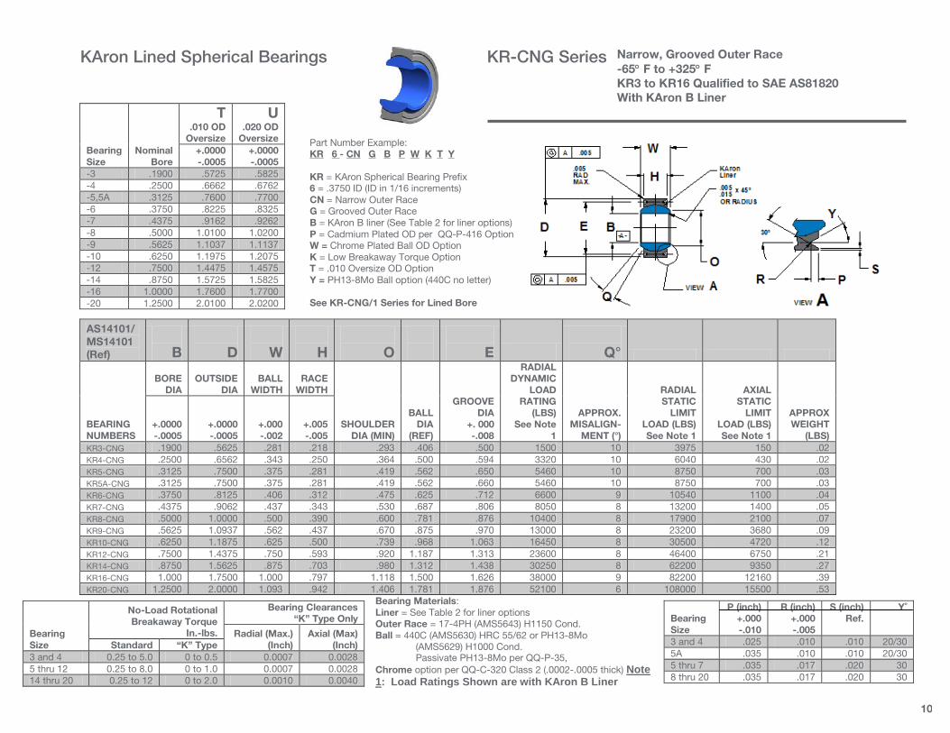
Bearing Materials: Liner = See Table 2 for liner options Outer Race = 17-4PH (AMS5643) H1150 Cond. Ball = 440C (AMS5630) HRC 55/62 or PH13-8Mo (AMS5629) H1000 Cond. Passivate PH13-8Mo per QQ-P-35,
Chrome option per QQ-C-320 Class 2 (.0002-.0005 thick). Note 1: Load Ratings Shown are with KAron B Liner System
Bearing Size
Nominal Bore
T .010 OD
Oversize
U .020 OD
Oversize +.0000 -.0005
+.0000 -.0005
-3 .1900 .5725 .5825 -4 .2500 .6662 .6762 -5,5A .3125 .7600 .7700 -6 .3750 .8225 .8325 -7 .4375 .9162 .9262 -8 .5000 1.0100 1.0200 -9 .5625 1.1037 1.1137 -10 .6250 1.1975 1.2075 -12 .7500 1.4475 1.4575 -14 .8750 1.5725 1.5825 -16 1.0000 1.7600 1.7700 -20 1.2500 2.0100 2.0200
AS14104/ MS14104 (Ref)
B
D
W
H
O
F
Q°
BEARING NUMBERS
BORE
DIA
OUTSIDE
DIA
BALL
WIDTH
RACE
WIDTH
SHOULDER
DIA (MIN)
BALL
DIA (REF)
CHAMFER
X 45°
RADIAL DYNAMIC
LOAD RATING
(LBS) See Note
1
APPROX.
MISALIGN- MENT (°)
RADIAL STATIC
LIMIT LOAD (LBS) See Note 1
AXIAL
STATIC LIMIT
LOAD (LBS) See Note 1
APPROX WEIGHT
(LBS) +.0000 -.0005
+.0000 -.0005
+.000 -.002
+.005 -.005
KR3-CN .1900 .5625 .281 .218 .293 .406 1500 10 3975 150 .02 KR4-CN .2500 .6562 .343 .250 .364 .500 .010/.020 3320 10 6040 430 .02 KR5-CN .3125 .7500 .375 .281 .419 .562 5460 10 8750 700 .03 KR6-CN .3750 .8125 .406 .312 .475 .625 6600 9 10540 1100 .04 KR7-CN .4375 .9062 .437 .343 .530 .687 8050 8 13200 1400 .05 KR8-CN .5000 1.0000 .500 .390 .600 .781 .020/.030 10400 8 17900 2100 .07 KR9-CN .5625 1.0937 .562 .437 .670 .875 13000 8 23200 3680 .09 KR10-CN .6250 1.1875 .625 .500 .739 .968 16450 8 30500 4720 .12 KR12-CN .7500 1.4375 .750 .593 .920 1.187 23600 8 46400 6750 .21 KR14-CN .8750 1.5625 .875 .703 .980 1.312 .030/.040 30250 8 62200 9350 .27 KR16-CN 1.000 1.7500 1.000 .797 1.118 1.500 38000 9 82200 12160 .39 KR20-CN 1.2500 2.0000 1.093 .942 1.406 1.781 52100 6 108000 15500 .53
Bearing Size
No-Load Rotational Breakaway Torque
In.-lbs.
Bearing Clearances “K” Type Only
Radial (Max.) (inch)
Axial (Max) (inch) Standard “K” Type
3 and 4 0.25 to 5.0 0 to 0.5 0.0007 0.0028 5 thru 12 0.25 to 8.0 0 to 1.0 0.0007 0.0028 14 thru 20 0.25 to 12 0 to 2.0 0.0010 0.0040
Part Number Example: KR 6 - CN B P W K T Y KR = Basic KAron Spherical Bearing Prefix 6 = .3750 ID (ID in 1/16 increments) CN = Narrow Chamfered Outer Race B = KAron B liner (See Table 2 for liner options) P = Cadmium Plated OD per QQ-P-416 Option W = Chrome Plated Ball OD Option K = Low Breakaway Torque Option T = .010 Oversize OD Option Y = PH13-8Mo Ball option (440C no letter) See KR-CN/4 Series for Lined Bore
Narrow, Chamfered Outer Race -65° F to +325° F KR3 to KR16 Qualified to SAE AS81820 With KAron B Liner
KAron Lined Spherical Bearings KR-CN Series
10
Bearing Materials: Liner = See Table 2 for liner options Outer Race = 17-4PH (AMS5643) H1150 Cond. Ball = 440C (AMS5630) HRC 55/62 or PH13-8Mo
(AMS5629) H1000 Cond. Passivate PH13-8Mo per QQ-P-35,
Chrome option per QQ-C-320 Class 2 (.0002-.0005 thick) Note 1: Load Ratings Shown are with KAron B Liner
Bearing Size
Nominal Bore
T .010 OD
Oversize
U .020 OD
Oversize +.0000 -.0005
+.0000 -.0005
-3 .1900 .5725 .5825 -4 .2500 .6662 .6762 -5,5A .3125 .7600 .7700 -6 .3750 .8225 .8325 -7 .4375 .9162 .9262 -8 .5000 1.0100 1.0200 -9 .5625 1.1037 1.1137 -10 .6250 1.1975 1.2075 -12 .7500 1.4475 1.4575 -14 .8750 1.5725 1.5825 -16 1.0000 1.7600 1.7700 -20 1.2500 2.0100 2.0200
AS14101/ MS14101 (Ref)
B
D
W
H
O
E
Q°
BEARING NUMBERS
BORE
DIA
OUTSIDE
DIA
BALL
WIDTH
RACE
WIDTH
SHOULDER
DIA (MIN)
BALL
DIA (REF)
GROOVE
DIA +. 000 -.008
RADIAL DYNAMIC
LOAD RATING
(LBS) See Note
1
APPROX.
MISALIGN- MENT (°)
RADIAL STATIC
LIMIT LOAD (LBS) See Note 1
AXIAL
STATIC LIMIT
LOAD (LBS) See Note 1
APPROX WEIGHT
(LBS) +.0000 -.0005
+.0000 -.0005
+.000 -.002
+.005 -.005
KR3-CNG .1900 .5625 .281 .218 .293 .406 .500 1500 10 3975 150 .02 KR4-CNG .2500 .6562 .343 .250 .364 .500 .594 3320 10 6040 430 .02 KR5-CNG .3125 .7500 .375 .281 .419 .562 .650 5460 10 8750 700 .03 KR5A-CNG .3125 .7500 .375 .281 .419 .562 .660 5460 10 8750 700 .03 KR6-CNG .3750 .8125 .406 .312 .475 .625 .712 6600 9 10540 1100 .04 KR7-CNG .4375 .9062 .437 .343 .530 .687 .806 8050 8 13200 1400 .05 KR8-CNG .5000 1.0000 .500 .390 .600 .781 .876 10400 8 17900 2100 .07 KR9-CNG .5625 1.0937 .562 .437 .670 .875 .970 13000 8 23200 3680 .09 KR10-CNG .6250 1.1875 .625 .500 .739 .968 1.063 16450 8 30500 4720 .12 KR12-CNG .7500 1.4375 .750 .593 .920 1.187 1.313 23600 8 46400 6750 .21 KR14-CNG .8750 1.5625 .875 .703 .980 1.312 1.438 30250 8 62200 9350 .27 KR16-CNG 1.000 1.7500 1.000 .797 1.118 1.500 1.626 38000 9 82200 12160 .39 KR20-CNG 1.2500 2.0000 1.093 .942 1.406 1.781 1.876 52100 6 108000 15500 .53
Bearing Size
No-Load Rotational Breakaway Torque
In.-lbs.
Bearing Clearances “K” Type Only
Radial (Max.) (Inch)
Axial (Max) (Inch) Standard “K” Type
3 and 4 0.25 to 5.0 0 to 0.5 0.0007 0.0028 5 thru 12 0.25 to 8.0 0 to 1.0 0.0007 0.0028 14 thru 20 0.25 to 12 0 to 2.0 0.0010 0.0040
Bearing Size
P (inch) +.000 -.010
R (inch) +.000 -.005
S (inch) Ref.
Y˚
3 and 4 .025 .010 .010 20/30 5A .035 .010 .010 20/30 5 thru 7 .035 .017 .020 30 8 thru 20 .035 .017 .020 30
Part Number Example: KR 6 - CN G B P W K T Y KR = KAron Spherical Bearing Prefix 6 = .3750 ID (ID in 1/16 increments) CN = Narrow Outer Race G = Grooved Outer Race B = KAron B liner (See Table 2 for liner options) P = Cadmium Plated OD per QQ-P-416 Option W = Chrome Plated Ball OD Option K = Low Breakaway Torque Option T = .010 Oversize OD Option Y = PH13-8Mo Ball option (440C no letter) See KR-CNG/1 Series for Lined Bore
Narrow, Grooved Outer Race -65° F to +325° F KR3 to KR16 Qualified to SAE AS81820 With KAron B Liner
KAron Lined Spherical Bearings KR-CNG Series

11
Bearing Materials: Liner = See Table 2 for liner options Outer Race = 17-4PH (AMS5643) H1150 Cond. Ball = 440C (AMS5630) HRC 55/62 or PH13-8Mo (AMS5629) H1000 Cond. Passivate PH13-8Mo per QQ-P-35,
Chrome option per QQ-C-320 Class 2 (.0002-.0005 thick). Note 1: Load Ratings Shown are with KAron B Liner System
Bearing Size
Nominal Bore
T .010 OD
Oversize
U .020 OD
Oversize +.0000 -.0005
+.0000 -.0005
-3 .1900 .6350 .6450 -4 .2500 .6350 .6450 -5 .3125 .6975 .7075 -6 .3750 .8225 .8325 -7 .4375 .9475 .9575 -8 .5000 1.0100 1.0200 -9 .5625 1.1350 1.1450 -10 .6250 1.1975 1.2075 -12 .7500 1.3850 1.3950 -14 .8750 1.6350 1.6450 -16 1.0000 2.1350 2.1450 -20 1.2500 2.3850 2.3950
AS14102/ MS14102 (Ref)
B
D
W
H
O
F
Q°
BEARING NUMBERS
BORE
DIA
OUTSIDE
DIA
BALL
WIDTH
RACE
WIDTH SHOULDER
DIA (MIN)
BALL
DIA (REF)
CHAMFER
X 45°
RADIAL DYNAMIC
LOAD RATING (LBS)
See Note 1
APPROX.
MISALIGN- MENT (°)
RADIAL STATIC
LIMIT LOAD (LBS) See Note 1
AXIAL STATIC
LIMIT LOAD (LBS) See Note 1
APPROX WEIGHT
(LBS) +.0000 -.0005
+.0000 -.0005
+.000 -.002
+.005 -.005
KR3-CW .1900 .6250 .437 .327 .300 .531 4900 15 2500 1770 .03 KR4-CW .2500 .6250 .437 .327 .300 .531 .015/.025 4900 15 5500 1770 .03 KR5-CW .3125 .6875 .437 .317 .360 .562 6050 14 9400 1640 .04 KR6-CW .3750 .8125 .500 .406 .466 .687 8310 8 13700 2630 .06 KR7-CW .4375 .9375 .562 .442 .537 .781 11750 10 20700 3650 .08 KR8-CW .5000 1.0000 .625 .505 .607 .875 .020/.030 14950 9 21400 4970 .10 KR9-CW .5625 1.1250 .687 .536 .721 1.000 18100 10 26600 5370 .14 KR10-CW .6250 1.1875 .750 .567 .747 1.062 20250 12 29000 6130 .16 KR12-CW .7500 1.3750 .875 .630 .845 1.218 26200 13 37000 7730 .24 KR14-CW .8750 1.6250 .875 .755 .995 1.375 .030/.040 33600 6 65200 10800 .35 KR16-CW 1.000 2.1250 1.375 1.005 1.269 1.875 56250 12 104000 19300 .97 KR20-CW 1.2500 2.3750 1.500 1.130 1.460 2.093 65900 14 153000 21400 1.10
Bearing Size
No-Load Rotational Breakaway Torque
In.-lbs.
Bearing Clearances “K” Type Only
Radial (Max.) (Inch)
Axial (Max) (Inch) Standard “K” Type
3 and 4 0.25 to 5.0 0 to 0.5 0.0007 0.0028 5 thru 12 0.25 to 8.0 0 to 1.0 0.0007 0.0028 14 thru 20 0.25 to 12 0 to 2.0 0.0010 0.0040
Part Number Example: KR 6 - CW B P W K T Y KR = KAron Spherical Bearing Prefix 6 = .3750 ID (ID in 1/16 increments) CW = Chamfered Wide Outer Race B = KAron B liner (See Table 2 for liner options) P = Cadmium Plated OD per QQ-P-416 Option W = Chrome Plated Ball OD Option K = Low Breakaway Torque Option T = .010 Oversize OD Option Y = PH13-8Mo Ball option (440C no letter) See KR-CW/2 for Lined Bore
Wide, Chamfered Outer Race -65° F to +325° F KR3 to KR16 Qualified to SAE AS81820 With KAron B Liner
KAron Lined Spherical Bearings KR-CW Series

12
Bearing Size
Nominal Bore
T .010 OD
Oversize
U .020 OD
Oversize +.0000 -.0005
+.0000 -.0005
-3 .1900 .6350 .6450 -4 .2500 .6350 .6450 -5 .3125 .6975 .7075 -6 .3750 .8225 .8325 -7 .4375 .9475 .9575 -7A .4375 .9162 .9262 -8 .5000 1.0100 1.0200 -9 .5625 1.1350 1.1450 -10 .6250 1.1975 1.2075 -12 .7500 1.3850 1.3975 -14 .8750 1.6350 1.6450 -16 1.0000 2.1350 2.1450 -20 1.2500 2.3850 2.3975
AS14103/ MS14103 (Ref)
B
D
W
H
O
E
Q°
BEARING NUMBERS
BORE
DIA
OUTSIDE
DIA
BALL
WIDTH
RACE
WIDTH SHOULDER
DIA (MIN)
BALL
DIA (REF)
GROOVE DIA
+. 000 -.008
RADIAL
DYNAMIC LOAD
RATING (LBS)
APPROX.
MISALIGN- MENT (°)
RADIAL STATIC
LIMIT LOAD (LBS)
AXIAL
STATIC LIMIT
LOAD (LBS)
APPROX WEIGHT
(LBS) +.0000 -.0005
+.0000 -.0005
+.000 -.002
+.005 -.005
KR3-CWG .1900 .6250 .437 .327 .300 .531 .563 4900 15 2500 1770 .03 KR4-CWG .2500 .6250 .437 .327 .300 .531 .563 4900 15 5500 1770 .03 KR5-CWG .3125 .6875 .437 .317 .360 .562 .622 6050 14 9400 1640 .04 KR6-CWG .3750 .8125 .500 .406 .466 .687 .712 8310 8 13700 2630 .06 KR7-CWG .4375 .9375 .562 .442 .537 .781 .837 11750 10 20700 3650 .08 KR7A-CWG .4375 .9062 .562 .442 .537 .781 .806 11750 10 20700 3650 .08 KR8-CWG .5000 1.0000 .625 .505 .607 .875 .900 14950 9 21400 4970 .10 KR9-CWG .5625 1.1250 .687 .536 .721 1.000 1.025 18100 10 26600 5370 .14 KR10-CWG .6250 1.1875 .750 .567 .747 1.062 1.087 20250 12 29000 6130 .16 KR12-CWG .7500 1.3750 .875 .630 .845 1.218 1.251 26200 13 37000 7730 .24 KR14-CWG .8750 1.6250 .875 .755 .995 1.375 1.501 33600 6 65200 10800 .35 KR16-CWG 1.000 2.1250 1.375 1.005 1.269 1.875 2.001 56250 12 104000 19300 .97 KR20-CWG 1.2500 2.3750 1.500 1.130 1.460 2.093 2.251 65900 14 153000 21400 1.10
Bearing
Size
P (in) +.000 -.010
R (in) +.000 -.007
S (in) Ref.
Y˚
3 and 5 .025 .012 .010 20/30 6 thru 10 .035 .017 .020 30
10 thru 20 .055 .017 .020 30
Bearing
Size
No-Load Rotational Breakaway Torque
In.-lbs.
Bearing Clearances “K” Type Only
Radial (Max.) (Inch)
Axial (Max) (Inch) Standard “K” Type
3 and 4 0.25 to 5.0 0 to 0.5 0.0007 0.0028 5 thru 12 0.25 to 8.0 0 to 1.0 0.0007 0.0028
14 thru 20 0.25 to 12 0 to 2.0 0.0010 0.0040
Part Number Example: KR 6 - CW G B P W K T Y KR = KAron Spherical Bearing Prefix 6 = .3750 ID (ID in 1/16 increments) CW = Chamfered Wide Outer Race G = Grooved Outer Race B = KAron B liner (See Table 2 for liner options) P = Cadmium Plated OD per QQ-P-416 Option W = Chrome Plated Ball OD Option K = Low Breakaway Torque Option T = .010 Oversize OD Option Y = PH13-8Mo Ball option (440C no letter) See KR-CWG/3 for Lined Bore
Wide, Grooved Outer Race -65° F to +325° F KR3 to KR16 Qualified to SAE AS81820 With KAron B Liner
Bearing Materials: Liner = See Table 2 for liner options Outer Race = 17-4PH (AMS5643) H1150 Cond. Ball = 440C (AMS5630) HRC 55/62 or PH13-8Mo (AMS5629) H1000 Cond. Passivate PH13-8Mo per QQ-P-35, Chrome option per QQ-C-320 Class 2 (.0002-.0005 thick). Note 1: Load Ratings Shown are with KAron B Liner System
KAron Lined Spherical Bearings KR-CWG Series

13
Bearing Size
Maximum Bore
T .010 OD
Oversize +.0000 -.0005
U .020 OD
Oversize +.0000 -.0005
-3 .1910 .5725 .5825 -4 .2510 .6662 .6762 -5 .3135 .7600 .7700 -6 .3760 .8225 .8325 -7 .4385 .9162 .9262 -8 .5010 1.0100 1.0200 -9 .5635 1.1037 1.1137 -10 .6260 1.1975 1.2075 -12 .7510 1.4475 1.4575 -14 .8760 1.5725 1.5825 -16 1.0010 1.7600 1.7700 -20 1.2510 2.0100 2.0200
AS81820/4 M81820/4 (Ref)
B
D
W
H
F
Q°
BEARING NUMBERS
BORE
DIA
OUTSIDE
DIA
BALL
WIDTH
RACE
WIDTH BALL
DIA (REF)
CHAMFER
X 45°
RADIAL DYNAMIC
LOAD RATING (LBS)
See Note 1
APPROX.
MISALIGN- MENT (°)
RADIAL STATIC
LIMIT LOAD (LBS) See Note 1
AXIAL
STATIC LIMIT
LOAD (LBS) See Note 1
APPROX WEIGHT
(LBS) +.0000 -.0010
+.0000 -.0005
+.000 -.002
+.005 -.005
KR3-CN/4 .1910 .5625 .281 .218 .406 1500 10 3975 150 .02 KR4-CN/4 .2510 .6562 .343 .250 .500 .010/.020 2650 10 5550 430 .02 KR5-CN/4 .3135 .7500 .375 .281 .562 3700 10 7700 700 .03 KR6-CN/4 .3760 .8125 .406 .312 .625 4900 9 10200 1100 .04 KR7-CN/4 .4385 .9062 .437 .343 .687 6700 8 12950 1400 .05 KR8-CN/4 .5010 1.0000 .500 .390 .781 .020/.030 8250 8 17250 2100 .07 KR9-CN/4 .5635 1.0937 .562 .437 .875 10500 8 22150 3680 .09 KR10-CN/4 .6260 1.1875 .625 .500 .968 13250 8 27700 4720 .12 KR12-CN/4 .7510 1.4375 .750 .593 1.187 19400 8 40500 6750 .21 KR14-CN/4 .8760 1.5625 .875 .703 1.312 .030/.040 26750 8 55950 9350 .27 KR16-CN/4 1.0010 1.7500 1.000 .797 1.500 35250 9 73800 12160 .39 KR20-CN/4 1.2510 2.0000 1.093 .942 1.781 48250 6 108000 15500 .53
Bearing Size
No-Load Rotational Breakaway Torque
In.-lbs.
Bearing Clearances “K” Type Only
Radial (Max.) (inch)
Axial (Max) (inch) Standard “K” Type
3 and 4 1.0 to 5.0 0 to 0.5 0.0007 0.0028 5 thru 12 1.0 to 15.0 0 to 1.0 0.0007 0.0028 14 thru 20 1.0 to 25.0 0 to 2.0 0.0010 0.0040
Part Number Example: KR 6 - CN /4 B P W K T Y KR = KAron Spherical Bearing Prefix 6 = .3750 ID (ID in 1/16 increments) CN = Narrow Outer Race /4 = KAron Lined Bore (ID) B = KAron B liner (See Table 2 for liner options) P = Cadmium Plated OD per QQ-P-416 Option W = Chrome Plated Ball OD Option K = Low Breakaway Torque Option T = .010 Oversize OD Option Y = PH13-8Mo Ball option (440C no letter)
Bearing Materials: Liner = See Table 2 for liner options Outer Race = 17-4PH (AMS 5643) Condition H1150 Ball = 440C (AMS5630) HRC 55/62 or PH13-8Mo CRES (AMS5629) Condition H1000, Passivate PH13-8Mo per QQ-P-35 Chrome plate option per QQ-C-35 Class 2, (.0002-.0005 thick) Note 1: Load Ratings Shown are with KAron B Liner System
Narrow, Chamfered Outer Race Lined Bore, -65° F to +325° F KR4 to KR16 Qualified to SAE AS81820 With KAron B Liner
KAron Lined Spherical Bearings KR-CN/4 Series

14
Bearing Size
Nominal Bore
T .010 OD
Oversize
U .020 OD
Oversize +.0000 -.0005
+.0000 -.0005
-3 .1910 .5725 .5825 -4 .2510 .6662 .6762
-5 .3135 .7600 .7700 -6 .3760 .8225 .8325
-7 .4385 .9162 .9262 -8 .5010 1.0100 1.0200
-9 .5635 1.1037 1.1137 -10 .6230 1.1975 1.2075
-12 .7510 1.4475 1.4575 -14 .8760 1.5725 1.5825
-16 1.0010 1.7600 1.7700
-20 1.2510 2.0100 2.0200
AS81820/1 M81820/1 (REF)
B
D
W
H
E
Q°
BEARING NUMBERS
BORE
DIA
OUTSIDE
DIA
BALL
WIDTH
RACE
WIDTH BALL
DIA (REF)
GROOVE DIA
+. 000 -.008
RADIAL DYNAMIC
LOAD RATING (LBS)
See Note 1
APPROX.
MISALIGN- MENT (°)
RADIAL STATIC
LIMIT LOAD (LBS) See Note 1
AXIAL STATIC
LIMIT LOAD (LBS) See Note 1
APPROX WEIGHT
(LBS) +.0000 -.0010
+.0000 -.0005
+.000 -.002
+.005 -.005
KR3-CNG/1 .1910 .5625 .281 .218 .406 .500 1500 10 3975 150 .02 KR4-CNG/1 .2510 .6562 .343 .250 .500 .594 2650 10 6040 430 .02 KR5-CNG/1 .3135 .7500 .375 .281 .562 .650 3700 10 8750 700 .03 KR6-CNG/1 .3760 .8125 .406 .312 .625 .712 4900 9 10540 1100 .04 KR7-CNG/1 .4385 .9062 .437 .343 .687 .806 6700 8 13200 1400 .05 KR8-CNG/1 .5010 1.0000 .500 .390 .781 .876 8250 8 17900 2100 .07 KR9-CNG/1 .5635 1.0937 .562 .437 .875 .970 10500 8 23200 3680 .09 KR10-CNG/1 .6260 1.1875 .625 .500 .968 1.063 13250 8 30500 4720 .12 KR12-CNG/1 .7510 1.4375 .750 .593 1.187 1.313 19400 8 46400 6750 .21 KR14-CNG/1 .8760 1.5625 .875 .703 1.312 1.438 26750 8 62200 9350 .27 KR16-CNG/1 1.0010 1.7500 1.000 .797 1.500 1.626 35250 9 82200 12160 .39 KR20-CNG/1 1.2510 2.0000 1.093 .942 1.781 1.876 47800 6 95600 15500 .53
Bearing Size
P (inch) +.000 -.010
R (inch) +.000 -.005
S (inch) Ref.
Y˚
3 and 4 .025 .010 .010 20/30 5 thru 7 .035 .017 .020 30 8 thru 20 .055 .017 .020 30
Bearing Size
No-Load Rotational Breakaway Torque
In.-lbs.
Bearing Clearances “K” Type Only
Radial (Max.) (Inch)
Axial (Max) (Inch) Standard “K” Type
3 and 4 0.25 to 5.0 0 to 0.5 0.0007 0.0028 5 thru 12 0.25 to 8.0 0 to 1.0 0.0007 0.0028 14 thru 20 0.25 to 12 0 to 2.0 0.0010 0.0040
Part Number Example: KR 6 - CN G /1 B P W K T Y KR = Basic KAron Spherical Bearing Prefix 6 = .3750 ID (ID in 1/16 increments) CN = Narrow Outer Race G = Grooved Outer Race /1 = KAron Lined Bore (ID) B = KAron B liner (See Table 2 for liner options) P = Cadmium Plated OD per QQ-P-416 Option W = Chrome Plated Ball OD Option K = Low Breakaway Torque Option T = .010 Oversize OD Option Y = PH13-8Mo Ball option (440C no letter)
Narrow, Grooved Outer Race Lined Bore, -65° F to +325° F KR4 to KR16 Qualified to SAE AS81820 With KAron B Liner
Bearing Materials: Liner = See Table 2 for liner options Outer Race = 17-4PH (AMS5643) H1150 Cond. Ball = 440C (AMS5630) HRC 55/62 or PH13-8Mo (AMS5629) H1000 Cond. Passivate PH13-8Mo per QQ-P-35, Chrome option per QQ-C-320 Class 2 (.0002-.0005 thick). Note 1: Load ratings Shown are with KAron B Liner System
KAron Lined Spherical Bearings KR-CNG/1 Series

15
Bearing Size
Maximum Bore
T .010 OD
Oversize
U .020 OD
Oversize +.0000 -.0005
+.0000 -.0005
-3 .1910 .6350 .6450 -4 .2510 .6350 .6450 -5 .3135 .6975 .7075 -6 .3760 .8225 .8325 -7 .4385 .9475 .9575 -8 .5010 1.0100 1.0200 -9 .5635 1.1350 1.1450 -10 .6260 1.1975 1.2075 -12 .7510 1.3850 1.3950 -14 .8760 1.6350 1.6450 -16 1.0010 2.1350 2.1450 -20 1.2510 2.3850 2.3950
AS81820/2 M81820/2 (Ref)
B
D
W
H
F
Q°
BEARING NUMBERS
BORE
DIA
OUTSIDE
DIA
BALL
WIDTH
RACE
WIDTH BALL
DIA (REF)
CHAMFER
X 45°
RADIAL DYNAMIC
LOAD RATING (LBS)
See Note 1
APPROX.
MISALIGN- MENT (°)
RADIAL STATIC
LIMIT LOAD (LBS) See Note 1
AXIAL
STATIC LIMIT
LOAD (LBS) See Note 1
APPROX WEIGHT
(LBS) +.0000 -.0010
+.0000 -.0005
+.000 -.002
+.005 -.005
KR3-CW/2 .1910 .6250 .437 .327 .531 1500 15 3975 1770 .03 KR4-CW/2 .2510 .6250 .437 .327 .531 .010/.020 2650 15 5550 1770 .03 KR5-CW/2 .3135 .6875 .437 .317 .562 4450 14 9250 1640 .04 KR6-CW/2 .3760 .8125 .500 .406 .687 6200 8 13000 2630 .06 KR7-CW/2 .4385 .9375 .562 .442 .781 8250 10 17250 3650 .08 KR8-CW/2 .5010 1.0000 .625 .505 .875 .020/.030 10600 9 21400 4970 .10 KR9-CW/2 .5635 1.1250 .687 .536 1.000 13200 10 25600 5370 .14 KR10-CW/2 .6260 1.1875 .750 .567 1.062 15150 12 29000 6130 .16 KR12-CW/2 .7510 1.3750 .875 .630 1.218 24500 13 37000 7730 .24 KR14-CW/2 .8760 1.6250 .875 .755 1.375 .030/.040 28750 6 56000 10800 .35 KR16-CW/2 1.0010 2.1250 1.375 1.005 1.875 49300 12 103300 19300 .97 KR20-CW/2 1.2510 2.3750 1.5000 1.130 2.093 67500 14 136900 21400 1.10
Bearing Size
No-Load Rotational Breakaway Torque
In.-lbs.
Bearing Clearances “K” Type Only
Radial (Max.) (inch)
Axial (Max) (inch) Standard “K” Type
3 to 12 1.0 to 15.0 0 to 1.0 0.0007 0.0021 14 thru 20 1.0 to 25.0 0 to 2.0 0.0010 0.0030
Part Number Example: KR 6 - CW /2 B P W K T Y KR = Basic KAron Spherical Bearing Prefix 6 = .3750 ID (ID in 1/16 increments) CW = Wide Chamfered Outer Race /2 = KAron Lined Bore B = KAron B liner (See Table 2 for liner options) P = Cadmium Plated OD per QQ-P-416 Option W = Chrome Plated Ball OD Option K = Low Breakaway Torque Option T = .010 Oversize OD Option Y = PH13-8Mo Ball option (440C no letter)
Wide, Chamfered Outer Race Lined Bore, -65° F to +325° F KR5 to KR16 Qualified to SAE AS81820 With KAron B Liner
Bearing Materials: Liner = See Table 2 for liner options Outer Race = 17-4PH (AMS5643) H1150 Cond. Ball = 440C (AMS5630) HRC 55/62 or PH13-8Mo (AMS5629) H1000 Cond. Passivate PH13-8Mo per QQ-P-35, Chrome option per QQ-C-320 Class 2 (.0002-
.0005 thick). Note 1: Load Ratings Shown are with KAron B Liner System
KAron Lined Spherical Bearings KR-CW/2 Series

16
Bearing Size
Nominal Bore
T .010 OD
Oversize
U .020 OD
Oversize +.0000 -.0005
+.0000 -.0005
-4 .2510 .6350 .6450 -5 .3135 .6975 .7075 -6 .3760 .8225 .8325 -7 .4385 .9475 .9575 -7A .4385 .9162 .9262 -8 .5010 1.0100 1.0200 -9 .5635 1.1350 1.1450 -10 .6230 1.1975 1.2075 -12 .7510 1.3850 1.3975 -14 .8760 1.6350 1.6450 -16 1.0010 2.1350 2.1450 -20 1.2510 2.3850 2.3975
Bearing Size
P (inch) +.000 -.010
R (inch) +.000 -.005
S (inch) Ref.
Y˚
3 and 4 .025 .010 .010 20/30 5 .035 .017 .020 30 6 thru 20 .055 .017 .020 30
AS81820/3 M81820/3
B
D
W
H
E
Q°
BEARING NUMBERS
BORE
DIA
OUTSIDE
DIA
BALL
WIDTH
RACE
WIDTH BALL
DIA (REF)
GROOVE
DIA +. 000 -.008
RADIAL DYNAMIC
LOAD RATING (LBS)
See Note 1
APPROX.
MISALIGN- MENT (°)
RADIAL STATIC
LIMIT LOAD (LBS) See Note 1
AXIAL STATIC
LIMIT LOAD (LBS) See Note 1
APPROX WEIGHT
(LBS) +.0000 -.0010
+.0000 -.0005
+.000 -.002
+.005 -.005
KR3-CWG/3 .1910 .6250 .437 .327 .531 .563 1500 15 3975 1770 .03 KR4-CWG/3 .2510 .6250 .437 .327 .531 .563 2650 15 7100 1770 .03 KR5-CWG/3 .3135 .6875 .437 .317 .562 .622 4450 14 9300 1640 .04 KR6-CWG/3 .3760 .8125 .500 .406 .687 .712 6200 8 13000 2630 .06 KR7-CWG/3 .4385 .9375 .562 .442 .781 .837 8250 10 17300 3650 .08 KR7A-CWG/3 .4385 .9062 .562 .442 .781 .806 8250 10 17300 3650 .08 KR8-CWG/3 .5010 1.0000 .625 .505 .875 .900 10500 9 21400 4970 .10 KR9-CWG/3 .5635 1.1250 .687 .536 1.000 1.025 13200 10 26500 5370 .14 KR10-CWG/3 .6260 1.1875 .750 .567 1.062 1.087 16150 12 29000 6130 .16 KR12-CWG/3 .7510 1.3750 .875 .630 1.218 1.251 24500 13 37000 7730 .24 KR14-CWG/3 .8760 1.6250 .875 .755 1.375 1.501 25750 6 56000 10800 .35 KR16-CWG/3 1.0010 2.1250 1.375 1.005 1.875 2.001 49300 12 103000 19300 .97 KR20-CWG/3 1.2510 2.3750 1.500 1.130 2.093 2.251 67500 14 140600 21400 1.10
Bearing Size
No-Load Rotational Breakaway Torque
In.-lbs.
Bearing Clearances “K” Type Only
Radial (Max.) (Inch)
Axial (Max) (Inch) Standard “K” Type
3 thru 12 1.0 to
15.0 0 to 1.0 0.0007 0.0021
14 thru 20 0.25 to
12 0 to 2.0 0.0010 0.0030
Part Number Example: KR 6 - CW G /3 B P W K T Y KR = Basic KAron Spherical Bearing Prefix 6 = .3750 ID (ID in 1/16 increments) CW = Chamfered Wide Outer Race G = Grooved Outer Race /3 = KAron Lined Bore (ID) B = KAron B liner (See Table 2 for liner options) P = Cadmium Plated OD per QQ-P-416 Option W = Chrome Plated Ball OD Option K = Low Breakaway Torque Option T = .010 Oversize OD Option Y = PH13-8Mo Ball option (440C no letter)
Wide, Grooved Outer Race Lined Bore, -65° F to +325° F KR5 to KR16 Qualified to SAE AS81820 With KAron B Liner
Bearing Materials: Liner = See Table 2 for liner options Outer Race = 17-4PH (AMS5643) H1150 Cond. Ball = 440C (AMS5630) HRC 55/62 or PH13- 8Mo (AMS5629) H1000 Cond. Passivate PH13- 8Mo per QQ-P-35, Chrome option per QQ-C-320 Class 2 (.0002-.0005 thick). Note 1: Load Ratings Shown are with KAron B Liner System
KAron Lined Spherical Bearings KR-CWG/3 Series
17
B
D
W
H
O
F
See
Note 1
Q°
See
Note 1
See
Note 1
BEARING NUMBERS
BORE DIA
OUTSIDE DIA
BALL WIDTH
RACE WIDTH
SHOULDER DIA (MIN)
BALL DIA (REF)
CHAMFER
X 45°
RADIAL DYNAMIC
LOAD RATING (LBS)
APPROX. MISALIGN-
MENT (°)
RADIAL STATIC
LIMIT LOAD (LBS)
AXIAL STATIC
LIMIT LOAD (LBS)
APPROX WEIGHT
(LBS) +.0000 -.0005
+.0000 -.0005
+.000 -.002
+.005 -.005
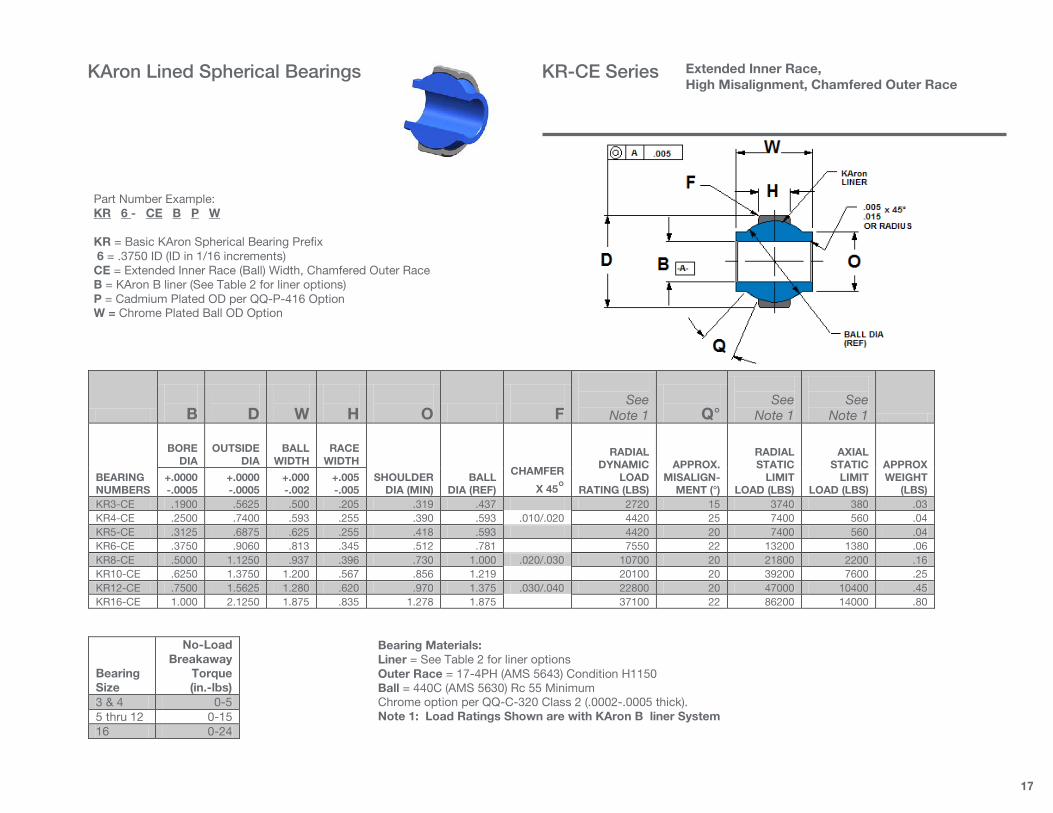
KR3-CE .1900 .5625 .500 .205 .319 .437 2720 15 3740 380 .03 KR4-CE .2500 .7400 .593 .255 .390 .593 .010/.020 4420 25 7400 560 .04 KR5-CE .3125 .6875 .625 .255 .418 .593 4420 20 7400 560 .04 KR6-CE .3750 .9060 .813 .345 .512 .781 7550 22 13200 1380 .06 KR8-CE .5000 1.1250 .937 .396 .730 1.000 .020/.030 10700 20 21800 2200 .16 KR10-CE .6250 1.3750 1.200 .567 .856 1.219 20100 20 39200 7600 .25 KR12-CE .7500 1.5625 1.280 .620 .970 1.375 .030/.040 22800 20 47000 10400 .45 KR16-CE 1.000 2.1250 1.875 .835 1.278 1.875 37100 22 86200 14000 .80
Bearing Size
No-Load Breakaway
Torque (in.-lbs)
3 & 4 0-5 5 thru 12 0-15 16 0-24
Part Number Example: KR 6 - CE B P W KR = Basic KAron Spherical Bearing Prefix 6 = .3750 ID (ID in 1/16 increments) CE = Extended Inner Race (Ball) Width, Chamfered Outer Race B = KAron B liner (See Table 2 for liner options) P = Cadmium Plated OD per QQ-P-416 Option W = Chrome Plated Ball OD Option
Extended Inner Race, High Misalignment, Chamfered Outer Race
Bearing Materials: Liner = See Table 2 for liner options Outer Race = 17-4PH (AMS 5643) Condition H1150 Ball = 440C (AMS 5630) Rc 55 Minimum Chrome option per QQ-C-320 Class 2 (.0002-.0005 thick). Note 1: Load Ratings Shown are with KAron B liner System
KAron Lined Spherical Bearings KR-CE Series

18
B
D
W
H
O
See
Note 1
Q°
See
Note 1
See
Note 1
BEARING NUMBERS
BORE DIA
OUTSIDE DIA
BALL WIDTH
RACE WIDTH
SHOULDER DIA (MIN)
BALL DIA
(REF)
RADIAL DYNAMIC
LOAD RATING (LBS)
APPROX. MISALIGN-
MENT (°)
RADIAL STATIC
LIMIT LOAD (LBS)
AXIAL STATIC
LIMIT LOAD (LBS)
APPROX WEIGHT
(LBS) +.0000 -.0005
+.0000 -.0005
+.000 -.002
+.005 -.005
KR3-CEG .1900 .5625 .500 .205 .319 .437 2720 15 3740 380 .03 KR4-CEG .2500 .7400 .593 .255 .390 .593 4420 25 7400 560 .04 KR5-CEG .3125 .6875 .625 .255 .418 .593 4420 20 7400 560 .04
KR6-CEG .3750 .9060 .813 .345 .512 .781 7550 22 13200 1380 .06 KR8-CEG .5000 1.1250 .937 .396 .730 1.000 10700 20 21800 2200 .16
KR10-CEG .6250 1.3750 1.200 .567 .856 1.219 20100 20 39200 7600 .25 KR12-CEG .7500 1.5625 1.280 .620 .970 1.375 22800 20 47000 10400 .45 KR16-CEG 1.000 2.1250 1.875 .835 1.278 1.875 37100 22 86200 14000 .80
Bearing Size
P +.000 -.015
R +.000 -.010
S +.000 -.010
X +.000 -.010
3 and 8 .030 .015 .020 .045 10 thru 12 .040 .020 .030 .055 16 .060 .020 .030 .080
Bearing Size
No-Load Breakaway
Torque (in.-lbs)
3 & 4 0-5 5 thru 12 0-15 16 0-24
Part Number Example: KR 6 - CE G B P W KR = Basic KAron Spherical Bearing Prefix 6 = .3750 ID (ID in 1/16 increments) CE = Extended Inner Race (Ball) Width G = Grooved Outer Race B = KAron B liner (See Table 2 for liner options) P = Cadmium Plated OD per QQ-P-416 Option W = Chrome Plated Ball OD Option
Extended Inner Race, High Misalignment, Grooved Outer Race
Bearing Materials: Liner = See Table 2 for liner options Outer Race = 17-4PH (AMS 5643) Condition H1150 Ball = 440C (AMS 5630) Rc 55 Minimum Chrome option per QQ-C-320 Class 2 (.0002-.0005 thick) Note 1: Load Ratings Shown are with KAron B Liner System
KAron Lined Spherical Bearings KR-CEG Series

19
:
KR( ) C SERIES B D W H E
SUGGESTED
MATING HOUSING
BORE SIZE
ULT.
STATIC LOAD (LBS)
SEE NOTES 1 & 2
BEARING NUMBER
BORE
DIA
OUTER RACE
DIA
BALL
WIDTH
BODY
WIDTH
CHAMFER
X 45° +.0000 - .0005
+.0000 - .0005
+.000 -.005
+.005 -.000
+.010 -.000
+.0000 -.0005
KR088-C .0880 .2500 .125 .100 .010 .2500 550 KR094-C .0938 .2812 .155 .120 .010 .2812 775 KR125-C .1250 .3620 .250 .172 .010 .3620 2050 KR156-C .1560 .4687 .281 .187 .010 .4687 2550
Ball Outer Race Liner
Material Hardness
AMS 5630 (440C)
Rc 55 MIN
AMS 5643 (17-4PH)
Rc 28 MIN
KAron See Table 2 for liner
options
Spherical Bearing Miniature
Part Number Example: KR 094 – C B KR = Basic KAron Part Number Prefix 094 = 0.094 ID (Bore Size IN 0.001 Inch Increments) C = Miniature Spherical Bearings Cartridge B = KAron B Liner, See Table 2 for liner options
NOTES 1. Load ratings shown are based on KAron B liner system, See Table 2 for liner options 2. Loads shown are based on bearing components only, bolt/pin shear is not considered. 3. No load rotational breakaway torque = 1 inch pound maximum
KAron Lined Spherical Bearings KR-C Series
20
Note 1: Load ratings are based on KAron B liner system.
M81935/2 SIZE B D L E F N W H O G C R Q° S J
LOAD RATINGS (LBS) See Note 1
WEIGHT MAX (LBS)
BEARING NUMBER
BORE
DIA
ROD END DIA.
THREAD LENGTH
MIN
THREAD
SIZE
BODY
LENGTH
SHANK
DIA
BALL
WIDTH
BODY
WIDTH MIN
BALL FLAT
+.010 -.010
+.010 -.062
+.002 -.010
MIN
REF DIA OR
DISTANCE ACROSS
CORNERS
MAX
HOUSING ID
ULT.
STATIC
FATIGUE
AXIAL
PROOF
+.0000 -
.0005 +.010 -.010
+.010 -.010
+.010 -.010
+.000 -.002
+.005 -.005
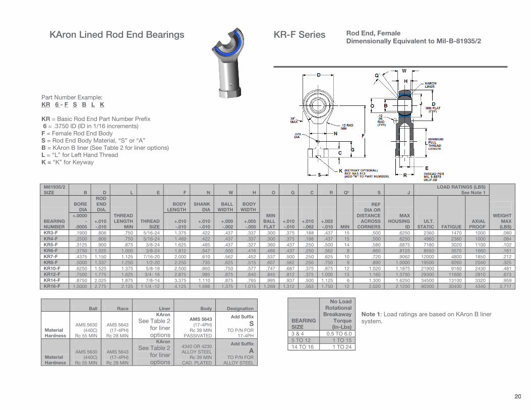
KR3-F .1900 .806 .750 5/16-24 1.375 .422 .437 .337 .300 .375 .188 .437 15 .500 .6250 2360 1470 1000 .080 KR4-F .2500 .806 .750 5/16-24 1.469 .422 .437 .337 .300 .375 .188 .437 15 .500 .6250 4860 2380 1000 .084 KR5-F .3125 .900 .875 3/8-24 1.625 .485 .437 .327 .360 .437 .250 .500 14 .580 .6875 7180 3020 1100 .102 KR6-F .3750 1.025 1.000 3/8-24 1.812 .547 .500 .416 .466 .437 .250 .562 8 .660 .8125 8550 3570 1660 .161 KR7-F .4375 1.150 1.125 7/16-20 2.000 .610 .562 .452 .537 .500 .250 .625 10 .720 .9062 12000 4800 1850 .212 KR8-F .5000 1.337 1.250 1/2-20 2.250 .735 .625 .515 .607 .562 .250 .750 9 .890 1.0000 19500 8260 2040 .325 KR10-F .6250 1.525 1.375 5/8-18 2.500 .860 .750 .577 .747 .687 .375 .875 12 1.020 1.1875 21900 9180 2430 .481 KR12-F .7500 1.775 1.625 3/4- 16 2.875 .985 .875 .640 .845 .812 .375 1.000 13 1.160 1.3750 29300 11600 2810 .673 KR14-F .8750 2.025 1.875 7/8-14 3.375 1.110 .875 .765 .995 .937 .500 1.125 6 1.300 1.6250 34500 13100 3320 .959 KR16-F 1.0000 2.775 2.125 1 1/4 -12 4.125 1.688 1.375 1.015 1.269 1.312 .563 1.750 12 2.020 2.1250 80300 30400 4340 2.717
BEARING SIZE
No Load Rotational
Breakaway Torque (In-Lbs)
3 & 4 0.5 TO 6.0 5 TO 12 1 TO 15 14 TO 16 1 TO 24
Ball Race Liner Body Designation
Material Hardness
AMS 5630 (440C)
Rc 55 MIN
AMS 5643 (17-4PH)
Rc 28 MIN
KAron See Table 2
for liner options
AMS 5643 (17-4PH)
Rc 39 MIN PASSIVATED
Add Suffix
S TO P/N FOR
17-4PH
Material Hardness
AMS 5630 (440C)
Rc 55 MIN
AMS 5643 (17-4PH)
Rc 28 MIN
KAron See Table 2
for liner options
4340 OR 4230 ALLOY STEEL
Rc 39 MIN CAD. PLATED
Add Suffix
A TO P/N FOR
ALLOY STEEL
Rod End, Female Dimensionally Equivalent to Mil-B-81935/2
Part Number Example: KR 6 - F S B L K KR = Basic Rod End Part Number Prefix 6 = .3750 ID (ID in 1/16 increments) F = Female Rod End Body S = Rod End Body Material, “S” or “A” B = KAron B liner (See Table 2 for liner options) L = “L” for Left Hand Thread K = “K” for Keyway
KAron Lined Rod End Bearings KR-F Series

21
KAron Lined Rod End Bearings
NOTE 1: Load ratings shown are based on KAron B liner system
M81935/1 SIZE B D L E F W H O G Q° J
LOAD RATINGS (LBS) See Note 1
WEIGHT MAX (LBS)
BEARING NUMBER
BORE
DIA
ROD END DIA.
THREAD LENGTH
MIN
THREAD
SIZE
BODY
LENGTH
BALL
WIDTH
BODY
WIDTH
MIN BALL FLAT
KEYWAY
FLAT
MIN
MAX
HOUSING ID
ULT.
STATIC
FATIGUE
AXIAL
PROOF +.0000 - .0005
+.010 -.010
+.010 -.010
+.000 -.002
+.005 -.005
+.000 -.020
KR3-M .1900 .806 .968 5/16-24 1.562 .437 .337 .300 .980 15 .6250 2360 1470 1000 .080 KR4-M .2500 .806 .968 5/16-24 1.562 .437 .337 .300 .980 15 .6250 4860 2380 1000 .084 KR5-M .3125 .900 1.187 5/16-24 1.875 .437 .327 .360 1.270 14 .6875 7180 3020 1100 .102 KR6-M .3750 1.025 1.187 3/8-24 1.938 .500 .416 .466 1.235 8 .8125 8550 3570 1660 .161 KR7-M .4375 1.150 1.281 7/16-20 2.125 .562 .452 .537 1.402 10 .9062 12000 4800 1850 .212 KR8-M .5000 1.337 1.468 1/2-20 2.438 .625 .515 .607 1.589 9 1.0000 19500 8260 2040 .325 KR10-M .6250 1.525 1.562 5/8-18 2.625 .750 .577 .747 1.683 12 1.1875 21900 9180 2430 .481 KR12-M .7500 1.775 1.687 3/4- 16 2.875 .875 .640 .845 1.808 13 1.3750 29300 11600 2810 .673 KR14-M .8750 2.025 2.000 7/8-14 3.375 .875 .765 .995 2.121 6 1.6250 34500 13100 3320 .959 KR16-M 1.0000 2.775 2.343 1 1/4 -12 4.125 1.375 1.015 1.269 2.464 12 2.1250 80300 30400 4340 2.717
Ball Race Liner Body Designation
Material Hardness
AMS 5630 (440C)
Rc 55 MIN
AMS 5643 (17-4PH)
Rc 28 MIN
KAron See Table 2
for liner options
AMS 5643 (17-4PH)
Rc 39 MIN PASSIVATED
Add Suffix
S TO P/N FOR
17-4PH
Material Hardness
AMS 5630 (440C)
Rc 55 MIN
AMS 5643 (17-4PH)
Rc 28 MIN
KAron See Table 2
for liner options
4340 OR 4230 ALLOY STEEL
Rc 39 MIN CAD. PLATED
Add Suffix
A TO P/N FOR
ALLOY STEEL
BEARING SIZE
No Load Rotational
Breakaway Torque (In-Lbs)
3 & 4 0.5 TO 6.0 5 TO 12 1 TO 15 14 TO 16 1 TO 24
Rod End, Male Dimensionally Equivalent to Mil-B-81935/1
Part Number Example: KR 6 - M S B L K KR = Basic Rod End Part Number Prefix 6 = .3750 ID (ID in 1/16 increments) M = Male Rod End Body S = Rod End Body Material, “S” or “A” B = KAron B liner (See Table 2 for liner options) L = “L” for Left Hand Thread K = “K” for Keyway
KAron Lined Rod End Bearings KR-M Series

22
:
KR( ) FS SERIES B D L E F N W H S
ULT.
STATIC LOAD (LBS)
SEE NOTES 1 & 2
BEARING NUMBER
BORE
DIA
ROD END DIA.
THREAD LENGTH
THREAD
SIZE UNF-3B
BODY
LENGTH
SHANK
DIA
BALL
WIDTH
BODY
WIDTH
REF DIA OR
DISTANCE ACROSS
CORNERS +.0000 - .0005
+.010 -.010
+.031 -.031
+.010 -.010
+.010 -.010
+.000 -.005
+.005 -.005
KR047-FS .0469 .189 .212 0-80 .357 .156 .109 .082 .200 225 KR094-FS .0938 .250 .260 3-56 .491 .187 .125 .084 .230 400 KR125-FS .1250 .469 .500 6-32 .937 .218 .250 .187 .263 850 KR156-FS .1560 .562 .625 8-32 1.125 .250 .281 .219 .295 1050
Ball Rod End Body Liner
Material Hardness
AMS 5630 (440C)
Rc 55 MIN
AMS 5643 (17-4PH)
Rc 28 MIN
KAron See Table 2 for Liner
Options
Rod End, Female Miniature
Part Number Example: KR 094 – FS B L K KR = Basic KAron Part Number Prefix 094 = .0938 ID, Bore Size In 0.001 Inch Increments FS = Miniature Female Rod End Body B = KAron B Liner, See Table 2 For Liner Options L = Left Hand Thread Option K = Keyway Option
NOTES 1. Load ratings shown are based on KAron B liner system 2. Loads shown are based on bearing components only, bolt/pin shear is not considered. 3. No load rotational breakaway torque = 1 inch pound maximum
KAron Lined Rod End Bearings KR-FS Series

23
:
KR( ) FM SERIES B D G E F W H
ULT.
STATIC LOAD (LBS)
SEE NOTES 1 & 2
BEARING NUMBER
BORE
DIA
ROD END DIA.
THREAD LENGTH
THREAD
SIZE UNF-3A
BODY
LENGTH
BALL
WIDTH
BODY
WIDTH +.0000 - .0005
+.010 -.010
+.031 -.031
+.010 -.010
+.000 -.005
+.005 -.005
KR047-MS .0469 .189 .212 0-80 .357 .109 .082 225 KR094-MS .0938 .250 .260 3-56 .491 .125 .084 400 KR125-MS .1250 .469 .500 6-32 .937 .250 .187 850
KR156-MS .1560 .562 .625 8-32 1.125 .281 .219 1050
Ball Rod End Body Liner
Material Hardness
AMS 5630 (440C)
Rc 55 MIN
AMS 5643 (17-4PH)
Rc 28 MIN
KAron See Table 2 for Liner
Options
NOTES 1. Load ratings shown are based on KAron B liner system. 2. Loads shown are based on bearing components only, bolt/pin shear is not considered. 3. No load rotational breakaway torque = 1 inch pound maximum
Part Number Example: KR 094 – MS B L K KR = Basic KAron Part Number Prefix 094 = .0938 ID, Bore Size In 0.001 Inch Increments MS = Miniature Male Rod End Body B = KAron B Liner, See Table 2 For Liner Options L = Left Hand Thread Option K = Keyway Option
Rod End, Male Miniature
KAron Lined Rod End Bearings KR-MS Series
24
M81934/1 B D T .010
O’SIZE DIA D
U .020
O’SIZE DIA D
L WEIGHT
LBS/INCH (REF)
BEARING NUMBER
BORE
DIA
OUTER
DIA.
Mil Spec Length Limits
(Suggested) + .0000 - .0010
See NOTE 1
See NOTE 1
See NOTE 1
MIN
MAX
AL
CRES
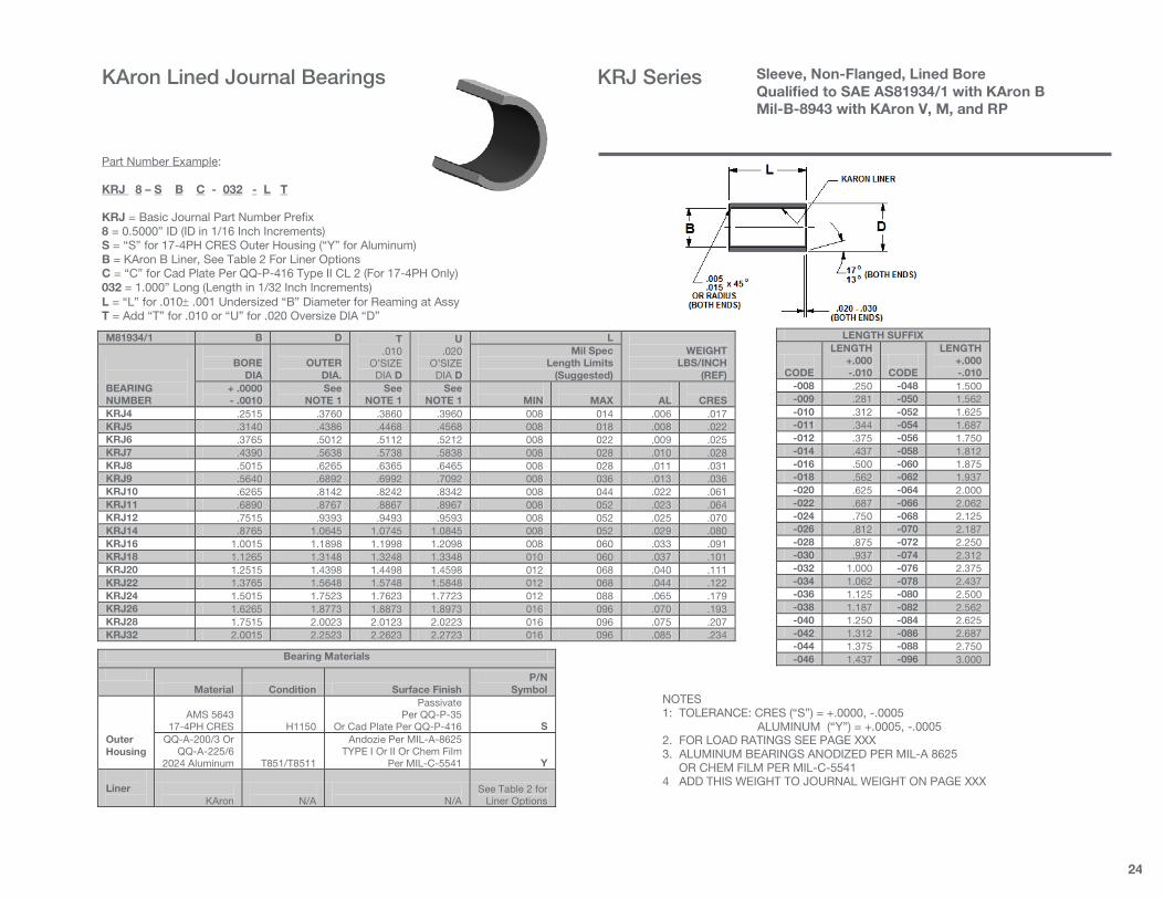
KRJ4 .2515 .3760 .3860 .3960 008 014 .006 .017 KRJ5 .3140 .4386 .4468 .4568 008 018 .008 .022 KRJ6 .3765 .5012 .5112 .5212 008 022 .009 .025 KRJ7 .4390 .5638 .5738 .5838 008 028 .010 .028 KRJ8 .5015 .6265 .6365 .6465 008 028 .011 .031 KRJ9 .5640 .6892 .6992 .7092 008 036 .013 .036 KRJ10 .6265 .8142 .8242 .8342 008 044 .022 .061 KRJ11 .6890 .8767 .8867 .8967 008 052 .023 .064 KRJ12 .7515 .9393 .9493 .9593 008 052 .025 .070 KRJ14 .8765 1.0645 1.0745 1.0845 008 052 .029 .080 KRJ16 1.0015 1.1898 1.1998 1.2098 008 060 .033 .091 KRJ18 1.1265 1.3148 1.3248 1.3348 010 060 .037 .101 KRJ20 1.2515 1.4398 1.4498 1.4598 012 068 .040 .111 KRJ22 1.3765 1.5648 1.5748 1.5848 012 068 .044 .122 KRJ24 1.5015 1.7523 1.7623 1.7723 012 088 .065 .179 KRJ26 1.6265 1.8773 1.8873 1.8973 016 096 .070 .193 KRJ28 1.7515 2.0023 2.0123 2.0223 016 096 .075 .207 KRJ32 2.0015 2.2523 2.2623 2.2723 016 096 .085 .234
LENGTH SUFFIX
CODE
LENGTH +.000 -.010
CODE
LENGTH +.000 -.010
-008 .250 -048 1.500 -009 .281 -050 1.562 -010 .312 -052 1.625 -011 .344 -054 1.687 -012 .375 -056 1.750 -014 .437 -058 1.812 -016 .500 -060 1.875 -018 .562 -062 1.937 -020 .625 -064 2.000 -022 .687 -066 2.062 -024 .750 -068 2.125 -026 .812 -070 2.187 -028 .875 -072 2.250 -030 .937 -074 2.312 -032 1.000 -076 2.375 -034 1.062 -078 2.437 -036 1.125 -080 2.500 -038 1.187 -082 2.562 -040 1.250 -084 2.625 -042 1.312 -086 2.687 -044 1.375 -088 2.750 -046 1.437 -096 3.000 Bearing Materials
Material Condition Surface Finish
P/N Symbol
Outer Housing
AMS 5643
17-4PH CRES
H1150
Passivate Per QQ-P-35
Or Cad Plate Per QQ-P-416
S QQ-A-200/3 Or
QQ-A-225/6 2024 Aluminum
T851/T8511
Andozie Per MIL-A-8625 TYPE I Or II Or Chem Film
Per MIL-C-5541
Y Liner
KAron
N/A
N/A
See Table 2 for Liner Options
Sleeve, Non-Flanged, Lined Bore Qualified to SAE AS81934/1 with KAron B Mil-B-8943 with KAron V, M, and RP
Part Number Example: KRJ 8 – S B C - 032 - L T KRJ = Basic Journal Part Number Prefix 8 = 0.5000” ID (ID in 1/16 Inch Increments) S = “S” for 17-4PH CRES Outer Housing (“Y” for Aluminum) B = KAron B Liner, See Table 2 For Liner Options C = “C” for Cad Plate Per QQ-P-416 Type II CL 2 (For 17-4PH Only) 032 = 1.000” Long (Length in 1/32 Inch Increments) L = “L” for .010± .001 Undersized “B” Diameter for Reaming at Assy T = Add “T” for .010 or “U” for .020 Oversize DIA “D”
KAron Lined Journal Bearings KRJ Series
NOTES 1: TOLERANCE: CRES (“S”) = +.0000, -.0005 ALUMINUM (“Y”) = +.0005, -.0005 2. FOR LOAD RATINGS SEE PAGE XXX 3. ALUMINUM BEARINGS ANODIZED PER MIL-A 8625 OR CHEM FILM PER MIL-C-5541 4 ADD THIS WEIGHT TO JOURNAL WEIGHT ON PAGE XXX
25
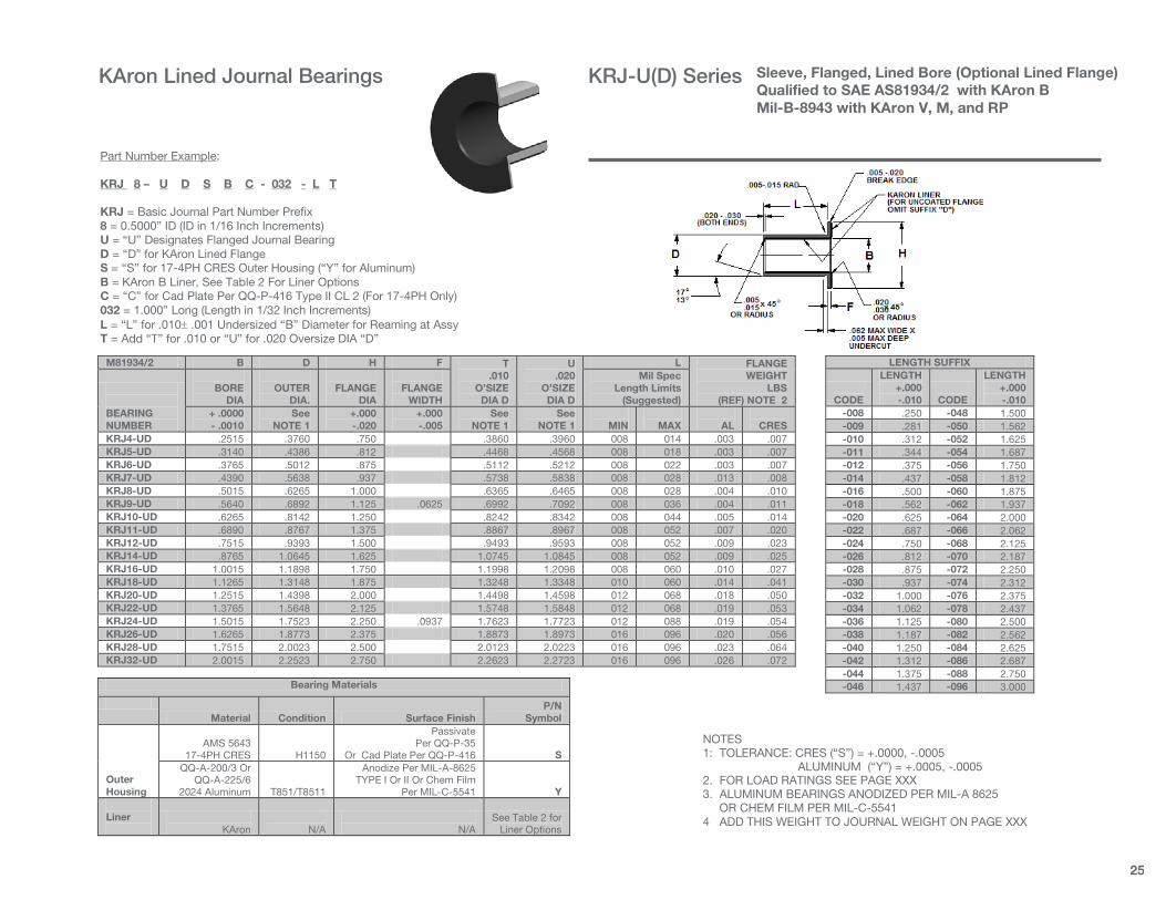
M81934/2 B D H F T .010
O’SIZE DIA D
U .020
O’SIZE DIA D
L FLANGE WEIGHT
LBS (REF) NOTE 2
BEARING NUMBER
BORE
DIA
OUTER
DIA.
FLANGE
DIA
FLANGE
WIDTH
Mil Spec Length Limits
(Suggested) + .0000 - .0010
See NOTE 1
+.000 -.020
+.000 -.005
See NOTE 1
See NOTE 1
MIN
MAX
AL
CRES
KRJ4-UD .2515 .3760 .750 .3860 .3960 008 014 .003 .007 KRJ5-UD .3140 .4386 .812 .4468 .4568 008 018 .003 .007 KRJ6-UD .3765 .5012 .875 .5112 .5212 008 022 .003 .007 KRJ7-UD .4390 .5638 .937 .5738 .5838 008 028 .013 .008 KRJ8-UD .5015 .6265 1.000 .6365 .6465 008 028 .004 .010 KRJ9-UD .5640 .6892 1.125 .0625 .6992 .7092 008 036 .004 .011 KRJ10-UD .6265 .8142 1.250 .8242 .8342 008 044 .005 .014 KRJ11-UD .6890 .8767 1.375 .8867 .8967 008 052 .007 .020 KRJ12-UD .7515 .9393 1.500 .9493 .9593 008 052 .009 .023 KRJ14-UD .8765 1.0645 1.625 1.0745 1.0845 008 052 .009 .025 KRJ16-UD 1.0015 1.1898 1.750 1.1998 1.2098 008 060 .010 .027 KRJ18-UD 1.1265 1.3148 1.875 1.3248 1.3348 010 060 .014 .041 KRJ20-UD 1.2515 1.4398 2.000 1.4498 1.4598 012 068 .018 .050 KRJ22-UD 1.3765 1.5648 2.125 1.5748 1.5848 012 068 .019 .053 KRJ24-UD 1.5015 1.7523 2.250 .0937 1.7623 1.7723 012 088 .019 .054 KRJ26-UD 1.6265 1.8773 2.375 1.8873 1.8973 016 096 .020 .056 KRJ28-UD 1.7515 2.0023 2.500 2.0123 2.0223 016 096 .023 .064 KRJ32-UD 2.0015 2.2523 2.750 2.2623 2.2723 016 096 .026 .072
LENGTH SUFFIX
CODE
LENGTH +.000 -.010
CODE
LENGTH +.000 -.010
-008 .250 -048 1.500 -009 .281 -050 1.562 -010 .312 -052 1.625 -011 .344 -054 1.687 -012 .375 -056 1.750 -014 .437 -058 1.812 -016 .500 -060 1.875 -018 .562 -062 1.937 -020 .625 -064 2.000 -022 .687 -066 2.062 -024 .750 -068 2.125 -026 .812 -070 2.187 -028 .875 -072 2.250 -030 .937 -074 2.312 -032 1.000 -076 2.375 -034 1.062 -078 2.437 -036 1.125 -080 2.500 -038 1.187 -082 2.562 -040 1.250 -084 2.625 -042 1.312 -086 2.687 -044 1.375 -088 2.750 -046 1.437 -096 3.000 Bearing Materials
Material Condition Surface Finish
P/N Symbol
Outer Housing
AMS 5643
17-4PH CRES
H1150
Passivate Per QQ-P-35
Or Cad Plate Per QQ-P-416
S QQ-A-200/3 Or
QQ-A-225/6 2024 Aluminum
T851/T8511
Anodize Per MIL-A-8625 TYPE I Or II Or Chem Film
Per MIL-C-5541
Y Liner
KAron
N/A
N/A
See Table 2 for Liner Options
Sleeve, Flanged, Lined Bore (Optional Lined Flange) Qualified to SAE AS81934/2 with KAron B Mil-B-8943 with KAron V, M, and RP
NOTES 1: TOLERANCE: CRES (“S”) = +.0000, -.0005 ALUMINUM (“Y”) = +.0005, -.0005 2. FOR LOAD RATINGS SEE PAGE XXX 3. ALUMINUM BEARINGS ANODIZED PER MIL-A 8625 OR CHEM FILM PER MIL-C-5541 4 ADD THIS WEIGHT TO JOURNAL WEIGHT ON PAGE XXX
Part Number Example: KRJ 8 – U D S B C - 032 - L T KRJ = Basic Journal Part Number Prefix 8 = 0.5000” ID (ID in 1/16 Inch Increments) U = “U” Designates Flanged Journal Bearing D = “D” for KAron Lined Flange S = “S” for 17-4PH CRES Outer Housing (“Y” for Aluminum) B = KAron B Liner, See Table 2 For Liner Options C = “C” for Cad Plate Per QQ-P-416 Type II CL 2 (For 17-4PH Only) 032 = 1.000” Long (Length in 1/32 Inch Increments) L = “L” for .010± .001 Undersized “B” Diameter for Reaming at Assy T = Add “T” for .010 or “U” for .020 Oversize DIA “D”
KAron Lined Journal Bearings KRJ-U(D) Series

26
Bearing Materials: Liner = See Table 2 for liner options Outer Race = 17-4PH (AMS5643) H1150 Cond. Ball = 440C (AMS5630) HRC 55/62 or PH13-8Mo (AMS5629) H1000 Cond. Passivate PH13-8Mo per QQ-P-35, Chrome option per QQ-C-320 Class 2 (0.005-0.013 thick). Note 1: Load Ratings Shown are with KAron B Liner System
Bearing Size
Nominal Bore
T .254 OD
Oversize
U .508 OD
Oversize +.0000 -.0127
+.0000 -.0127
-3 4.8260 14.5415 14.7955 -4 6.3500 16.9215 17.1755 -5,5A 7.9375 19.3040 19.5580 -6 9.5250 20.8915 21.1455 -7 11.1125 23.2715 23.5255 -8 12.7000 25.6540 25.9080 -9 14.2875 28.0340 28.2880 -10 15.8750 30.4165 30.6705 -12 19.0500 36.7665 37.0205 -14 22.2250 39.9415 40.1955 -16 25.4000 44.7040 44.9580 -20 31.7500 51.0540 51.3080
AS14104/ MS14104
METRIC - All Dimensions in Millimeters
B D W H O F Q°
BEARING NUMBERS
BORE
DIA
OUTSID
E DIA
BALL WIDT
H
RACE WIDT
H
SHOULDER
DIA (MIN)
BALL
DIA (REF)
CHAMFE
R X 45°
RADIAL DYNAMIC
LOAD RATING (KN)
See Note 1
APPROX.
MISALIGN-
MENT (°)
RADIAL STATIC
LIMIT LOAD (KN) See Note 1
AXIAL STATIC
LIMIT LOAD (KN) See Note 1
APPROX WEIGHT
(KG) +.000 -.013
+.000 -.013
+.000 -.051
+.127 -.127
KR3-CN 4.826 14.288 7.137 5.537 7.442 10.312 6.7 10 17.7 0.7 0.009 KR4-CN 6.350 16.668 8.712 6.350 9.246 12.700 .254/.508 14.8 10 26.9 1.9 0.009 KR5-CN 7.938 19.050 9.525 7.137 10.643 14.275 24.3 10 38.9 3.1 0.014 KR6-CN 9.525 20.638 10.312 7.925 12.065 15.875 29.4 9 46.9 4.9 0.018 KR7-CN 11.113 23.018 11.100 8.712 13.462 17.450 35.8 8 58.7 6.2 0.023 KR8-CN 12.700 25.400 12.700 9.906 15.240 19.837 .508/.762 46.3 8 79.6 9.3 0.032 KR9-CN 14.288 27.780 14.275 11.100 17.018 22.225 57.8 8 103.2 16.4 0.041 KR10-CN 15.875 30.163 15.875 12.700 18.771 24.587 73.2 8 135.7 21.0 0.054 KR12-CN 19.050 36.513 19.050 15.062 23.368 30.150 105.0 8 206.4 30.0 0.095 KR14-CN 22.225 39.688 22.225 17.856 24.892 33.325 .762/1.016 134.6 8 276.7 41.6 0.122 KR16-CN 25.400 44.450 25.400 20.244 28.397 38.100 169.0 9 365.7 54.1 0.177 KR20-CN 31.750 50.800 27.762 23.927 35.712 45.237 231.8 6 480.4 69.0 0.240
Bearing Size
No-Load Rotational Breakaway Torque
N-m
Bearing Clearances “K” Type Only
Radial (Max.) (mm)
Axial (Max) (mm) Standard “K” Type
3 and 4 0.03 to 0.56 0 to 0.090 0.018 0.071 5 thru 12 0.03 to 0.90 0 to 0.112 0.018 0.071 14 thru 20 0.03 to 1.35 0 to 0.225 0.025 0.102
Part Number Example: KR 6 - CN B P K T KR = Basic KAron Spherical Bearing Prefix 6 = 9.5250 mm ID CN = Narrow Chamfered Outer Race B = KAron B liner (See Table 2 for liner Options) P = Cadmium Plated OD per QQ-P-416 Option W = Chrome Plated Ball OD Option K = Low Breakaway Torque Option T = .010 Oversize OD Option Y = PH13-8Mo Ball option (440C no letter) See KR-CN/4 Series for Lined Bore
Narrow, Chamfered Outer Race -54° C to +163° C KR3 to KR16 Qualified to SAE AS81820 With KAron B Liner
KAron Lined Spherical Bearings KR-CN Series

27
Bearing Size
Nominal Bore
T .254 OD
Oversize
U .508 OD
Oversize +.0000 -.0127
+.0000 -.0127
-3 4.826 14.542 14.796 -4 6.350 16.921 17.175 -5,5A 7.938 19.304 19.558 -6 9.525 20.892 21.146 -7 11.113 23.271 23.525 -8 12.700 25.654 25.908 -9 14.288 28.034 28.288 -10 15.875 30.417 30.671 -12 19.050 36.767 37.021 -14 22.225 39.942 40.196 -16 25.400 44.704 44.958 -20 31.750 51.054 51.308
AS14101/ MS14101
METRIC - All Dimensions in Millimeters
B D W H O E Q°
BEARING NUMBERS
BORE
DIA
OUTSIDE
DIA
BALL
WIDTH
RACE
WIDTH
SHOULDER DIA (MIN)
BALL
DIA (REF)
GROOVE DIA
+. 000 -.203
RADIAL DYNAMIC
LOAD RATING (KN)
See Note 1
APPROX.
MISALIGN- MENT (°)
RADIAL STATIC
LIMIT LOAD (KN) See Note 1
AXIAL
STATIC LIMIT
LOAD (KN) See Note 1
APPROX WEIGHT
(KG) +.000 -.013
+.000 -.013
+.000 -.051
+.127 -.127
KR3-CNG 4.826 14.288 7.137 5.537 7.442 10.312 12.700 6.67 10 17.68 0.67 0.009 KR4-CNG 6.350 16.667 8.712 6.350 9.246 12.700 15.088 14.77 10 26.87 1.91 0.009 KR5-CNG 7.938 19.050 9.525 7.137 10.643 14.275 16.510 24.29 10 38.92 3.11 0.014 KR5A-CNG 7.938 19.050 9.525 7.137 10.643 14.275 16.764 24.29 10 38.92 3.11 0.014 KR6-CNG 9.525 20.638 10.312 7.925 12.065 15.875 18.085 29.36 9 46.89 4.89 0.018 KR7-CNG 11.113 23.017 11.100 8.712 13.462 17.450 20.472 35.81 8 58.72 6.23 0.023 KR8-CNG 12.700 25.400 12.700 9.906 15.240 19.837 22.250 46.26 8 79.63 9.34 0.032 KR9-CNG 14.288 27.780 14.275 11.100 17.018 22.225 24.638 57.83 8 103.20 16.37 0.041 KR10-CNG 15.875 30.163 15.875 12.700 18.771 24.587 27.000 73.18 8 135.68 21.00 0.054 KR12-CNG 19.050 36.513 19.050 15.062 23.368 30.150 33.350 104.98 8 206.41 30.03 0.095 KR14-CNG 22.225 39.688 22.225 17.856 24.892 33.325 36.525 134.56 8 276.69 41.59 0.122 KR16-CNG 25.400 44.450 25.400 20.244 28.397 38.100 41.300 169.04 9 365.66 54.09 0.177 KR20-CNG 31.750 50.800 27.762 23.927 35.712 45.237 47.650 231.76 6 480.43 68.95 0.240
Bearing Size
No-Load Rotational Breakaway Torque
N-m
Bearing Clearances “K” Type Only
Radial (Max.) (mm)
Axial (Max) (mm) Standard “K” Type
3 and 4 0.03 to 0.56 0 to 0.090 0.018 0.071 5 thru 12 0.03 to 0.90 0 to 0.112 0.018 0.071 14 thru 20 0.03 to 1.35 0 to 0.225 0.025 0.102
Bearing Size
P (mm) +.000 -.254
R (mm) +.000 -.127
S (mm) Ref.
Y˚
3 and 4 0.635 0.254 0.254 20/30 5A 0.890 0.254 0.254 20/30 5 thru 7 0.890 0.430 0.508 30 8 thru 20 1.00 0.430 0.508 30
Part Number Example: KR 6 - CN G B P K T KR = KAron Spherical Bearing Prefix 6 = 9.525 mm CN = Narrow Outer Race G = Grooved Outer Race B = KAron B liner (See Table 2 for liner options) P = Cadmium Plated OD per QQ-P- 416 Option W = Chrome Plated Ball OD Option K = Low Breakaway Torque Option T = .010 Oversize OD Option Y = PH13-8Mo Ball option (440C no letter) See KR-CNG/1 Series for Lined Bore
Bearing Materials: Liner = See Table 2 for liner options Outer Race = 17-4PH (AMS5643) H1150 Cond. Ball = 440C (AMS5630) HRC 55/62 or PH13-8Mo (AMS5629) H1000 Cond. Passivate PH13-8Mo per QQ-P-35, Chrome option per QQ-C-320 Class 2 (0.005-0.013 thick). Note 1: Load Ratings Shown are with KAron B Liner System
Narrow, Grooved Outer Race -54° C to +163° C KR3 to KR16 Qualified to SAE AS81820 With KAron B Liner
KAron Lined Spherical Bearings KR-CNG Series

28
Bearing Size
Nominal Bore
T .254 OD Oversize
U .508 OD Oversize
+.000 -.013
+.000 -.013
-3 4.826 16.129 16.383 -4 6.350 16.129 16.383 -5 7.938 17.717 17.971 -6 9.525 20.892 21.146 -7 11.113 24.067 24.321 -8 12.700 25.654 25.908 -9 14.288 28.829 29.083 -10 15.875 30.417 30.671 -12 19.050 35.179 35.433 -14 22.225 41.529 41.783 -16 25.400 54.229 54.483 -20 31.750 60.579 60.833
AS14102/ MS14102
B
D
W
H
O
F
Q°
BEARING NUMBERS
BORE
DIA
OUTSIDE
DIA
BALL
WIDTH
RACE
WIDTH SHOULDER
DIA (MIN)
BALL
DIA (REF)
CHAMFER
X 45°
RADIAL DYNAMIC
LOAD RATING (KN)
See Note 1
APPROX.
MISALIGN- MENT (°)
RADIAL STATIC
LIMIT LOAD (KN) See Note 1
AXIAL STATIC
LIMIT LOAD (KN) See Note 1
APPROX WEIGHT
(KG) +.000 -.013
+.000 -.013
+.000 -.051
+.127 -.127
KR3-CW 4.826 15.875 11.100 8.306 7.620 13.487 21.8 15 11.1 7.9 0.014 KR4-CW 6.350 15.875 11.100 8.306 7.620 13.487 .254/.508 21.8 15 24.5 7.9 0.014 KR5-CW 7.938 17.463 11.100 8.052 9.144 14.275 26.9 14 41.8 7.3 0.018 KR6-CW 9.525 20.638 12.700 10.312 11.836 17.450 37.0 8 60.9 11.7 0.027 KR7-CW 11.113 23.813 14.275 11.227 13.640 19.837 52.3 10 92.1 16.2 0.036 KR8-CW 12.700 25.400 15.875 12.827 15.418 22.225 .508/.762 66.5 9 95.2 22.1 0.045 KR9-CW 14.288 28.575 17.450 13.614 18.313 25.400 80.5 10 118.3 23.9 0.063 KR10-CW 15.875 30.163 19.050 14.402 18.974 26.975 90.1 12 129.0 27.3 0.073 KR12-CW 19.050 34.925 22.225 16.002 21.463 30.937 116.6 13 164.6 34.4 0.109 KR14-CW 22.225 41.275 22.225 19.177 25.273 34.925 .760/1.02 149.5 6 290.0 48.0 0.159 KR16-CW 25.400 53.975 34.925 25.527 32.233 47.625 250.2 12 462.6 85.9 0.440 KR20-CW 31.750 60.325 38.100 28.702 37.084 53.162 293.2 14 680.6 95.2 0.499
Bearing Size
No-Load Rotational Breakaway Torque
N-m
Bearing Clearances “K” Type Only
Radial (Max.) (mm)
Axial (Max) (mm) Standard “K” Type
3 and 4 0.03 to 0.56 0 to 0.090 0.018 0.071 5 thru 12 0.03 to 0.90 0 to 0.112 0.018 0.071 14 thru 20 0.03 to 1.35 0 to 0.225 0.025 0.102
Bearing Materials: Liner = See Table 2 for liner options Outer Race = 17-4PH (AMS5643) H1150 Cond. Ball = 440C (AMS5630) HRC 55/62 or PH13-8Mo (AMS5629) H1000 Cond. Passivate PH13-8Mo per QQ-P-35, Chrome option per QQ-C-320 Class 2 (0.005-0.013 thick). Note 1: Load Ratings Shown are with KAron B Liner System
METRIC All Dimensions in Millimeters
Part Number Example: KR 6 - CW B K P T KR = KAron Spherical Bearing Prefix 6 = 9.525 mm ID CW = Chamfered Wide Outer Race B = KAron B liner (See Table 2 for Liner Options) P = Cadmium Plated OD per QQ-P-416 Option W = Chrome Plated Ball OD Option K = Low Breakaway Torque Option T = .010 Oversize OD Option Y = PH13-8Mo Ball option (440C no letter) See KR-CW/2 for Lined Bore
Wide, Chamfered Outer Race -54° C to +163° C KR3 to KR16 Qualified to SAE AS81820 With KAron B Liner
KAron Lined Spherical Bearings KR-CW Series

29
Bearing Size
Nominal Bore
T .254 OD
Oversize
U .508 OD
Oversize +.000 -.013
+.000 -.013
-3 4.826 16.129 16.383 -4 6.350 16.129 16.383 -5 7.938 17.717 17.971 -6 9.525 20.892 21.146 -7 11.113 24.067 24.321 -7A 11.113 23.271 23.525 -8 12.700 25.654 25.908 -9 14.288 28.829 29.083 -10 15.875 30.417 30.671 -12 19.050 35.179 35.497 -14 22.225 41.529 41.783 -16 25.400 54.229 54.483 -20 31.750 60.579 60.897
AS14103/ MS14103
B
D
W
H
O
E
Q°
BEARING NUMBERS
BORE
DIA
OUTSIDE
DIA
BALL
WIDTH
RACE
WIDTH SHOULDER
DIA (MIN)
BALL
DIA (REF)
GROOVE DIA
+. 000 -.127
RADIAL
DYNAMIC LOAD
RATING (KN)
APPROX.
MISALIGN- MENT (°)
RADIAL STATIC
LIMIT LOAD (KN)
AXIAL
STATIC LIMIT
LOAD (KN)
APPROX WEIGHT
(KG) +.000 -.013
+.000 -.013
+.000 -.051
+.127 -.127
KR3-CWG 4.826 15.875 11.100 8.306 7.620 13.487 14.300 21.8 15 11.1 7.9 0.014 KR4-CWG 6.350 15.875 11.100 8.306 7.620 13.487 14.300 21.8 15 24.5 7.9 0.014 KR5-CWG 7.938 17.463 11.100 8.052 9.144 14.275 15.799 26.9 14 41.8 7.3 0.018 KR6-CWG 9.525 20.638 12.700 10.312 11.836 17.450 18.085 37.0 8 60.9 11.7 0.027 KR7-CWG 11.113 23.813 14.275 11.227 13.640 19.837 21.260 52.3 10 92.1 16.2 0.036 KR7A-CWG 11.113 23.017 14.275 11.227 13.640 19.837 20.472 52.3 10 92.1 16.2 0.036 KR8-CWG 12.700 25.400 15.875 12.827 15.418 22.225 22.860 66.5 9 95.2 22.1 0.045 KR9-CWG 14.288 28.575 17.450 13.614 18.313 25.400 26.035 80.5 10 118.3 23.9 0.063 KR10-CWG 15.875 30.163 19.050 14.402 18.974 26.975 27.610 90.1 12 129.0 27.3 0.073 KR12-CWG 19.050 34.925 22.225 16.002 21.463 30.937 31.775 116.5 13 164.6 34.4 0.109 KR14-CWG 22.225 41.275 22.225 19.177 25.273 34.925 38.125 149.5 6 290.0 48.0 0.159 KR16-CWG 25.400 53.975 34.925 25.527 32.233 47.625 50.825 250.2 12 462.6 85.9 0.440 KR20-CWG 31.750 60.325 38.100 28.702 37.084 53.162 57.175 293.1 14 680.6 95.2 0.499
Bearing Size
No-Load Rotational Breakaway Torque
N-m
Bearing Clearances “K” Type Only
Radial (Max.) (mm)
Axial (Max) (mm) Standard “K” Type
3 and 4 0.03 to 0.56 0 to 0.09 0.018 0.071 5 thru 12 0.03 to 0.90 0 to 0.11 0.018 0.071 14 thru 20 0.03 to 1.35 0 to 0.23 0.025 0.102
Bearing Size
P (mm) +.000 -.254
R (mm) +.000 -.178
S (mm) Ref. Y˚
3 and 5 .635 .305 .254 20/30 6 thru 10 .890 .430 .508 30 10 thru 20 1.400 .430 .508 30
Part Number Example: KR 6 - CW G B K P T KR = KAron Spherical Bearing Prefix 6 = 9.525 mm ID CW = Chamfered Wide Outer Race G = Grooved Outer Race B = KAron B liner (See Table 2 for Liner Options) P = Cadmium Plated OD per QQ-P-416 Option W = Chrome Plated Ball OD Option K = Low Breakaway Torque Option T = .254 Oversize OD Option Y = PH13-8Mo Ball option (440C no letter) See KR-CWG/3 for Lined Bore
METRIC All Dimensions in Millimeters
Bearing Materials: Liner = See Table 2 for liner options Outer Race = 17-4PH (AMA5643) H1150 Cond. Ball = 440C (AMS5630) HRC 55/62 or PH13-8Mo (AMS5629) H1000 Cond. Passivate PH13-8Mo per QQ-P-35, Chrome option per QQ-C-320 Class 2 (0.005-0.013 thick). Note 1: Load Ratings Shown are with KAron B Liner System
Wide, Grooved Outer Race -54° C to +163° C KR3 to KR16 Qualified to SAE AS81820 With KAron B Liner
KAron Lined Spherical Bearings KR-CWG Series

30
Bearing Size
Maximum Bore
T .254 OD
Oversize
U .508 OD
Oversize +.000 -.013
+.000 -.013
-3 4.851 14.542 14.796 -4 6.375 16.921 17.175 -5 7.963 19.304 19.558 -6 9.550 20.892 21.146 -7 11.138 23.271 23.525 -8 12.725 25.654 25.908 -9 14.313 28.034 28.288 -10 15.900 30.417 30.671 -12 19.075 36.767 37.021 -14 22.250 39.942 40.196 -16 25.425 44.704 44.958 -20 31.775 51.054 51.308
AS81820/4 M81820/4 (Ref)
B
D
W
H
F
Q°
BEARING NUMBERS
BORE DIA
OUTSIDE DIA
BALL WIDTH
RACE WIDTH BALL
DIA (REF)
CHAMFER X 45°
RADIAL DYNAMIC
LOAD RATING (KN)
See Note 1
APPROX. MISALIGN-
MENT (°)
RADIAL STATIC
LIMIT LOAD (KN) See Note 1
AXIAL STATIC
LIMIT LOAD (KN) See Note 1
APPROX WEIGHT
(KG) +.000 -.025
+.000 -.013
+.000 -.051
+.127 -.127
KR3-CN/4 4.851 14.288 7.137 5.537 10.312 6.7 10 17.7 0.7 0.009 KR4-CN/4 6.375 16.667 8.712 6.350 12.700 .25/.51 11.8 10 24.7 1.9 0.009 KR5-CN/4 7.963 19.050 9.525 7.137 14.275 16.5 10 34.3 3.1 0.014 KR6-CN/4 9.550 20.638 10.312 7.925 15.875 21.8 9 45.4 4.9 0.018 KR7-CN/4 11.138 23.017 11.100 8.712 17.450 29.8 8 57.6 6.2 0.023 KR8-CN/4 12.725 25.400 12.700 9.906 19.837 .51/.76 36.7 8 76.7 9.3 0.032 KR9-CN/4 14.313 27.780 14.275 11.100 22.225 46.7 8 98.5 16.4 0.041 KR10-CN/4 15.900 30.163 15.875 12.700 24.587 58.9 8 123.2 21.0 0.054 KR12-CN/4 19.075 36.513 19.050 15.062 30.150 86.3 8 180.2 30.0 0.095 KR14-CN/4 22.250 39.688 22.225 17.856 33.325 .76/1.02 119.0 8 248.9 41.6 0.122 KR16-CN/4 25.425 44.450 25.400 20.244 38.100 156.8 9 328.3 54.1 0.177 KR20-CN/4 31.775 50.800 27.762 23.927 45.237 214.6 6 480.4 69.0 0.240
Bearing Size
No-Load Rotational Breakaway Torque
N-m
Bearing Clearances “K” Type Only
Radial (Max.) (mm)
Axial (Max) (mm) Standard “K” Type
3 and 4 0.11 to 0.56 0 to 0.056 0.018 0.071 5 thru 12 0.11 to 1.70 0 to 0.11 0.018 0.071 14 thru 20 0.11 to 2.82 0 to 0.22 0.025 0.101
Bearing Materials: Liner = See Table 2 for liner options Outer Race = 17-4PH (AMS5643) H1150 Cond. Ball = 440C (AMS5630) HRC 55/62 or PH13-8Mo (AMS5629) H1000 Cond.Passivate PH13-8Mo per QQ-P-35, Chrome option per QQ-C-320 Class 2 (0.005-0.013 thick). Note 1: Load Ratings Shown are with KAron B Liner System
Part Number Example: KR 6 - CN /4 B K P T KR = KAron Spherical Bearing Prefix 6 = 9.525 mm ID CN = Narrow Outer Race /4 = KAron Lined Bore (ID) B = KAron B liner (See Table 2 for Liner Options) P = Cadmium Plated OD per QQ-P-416 Option W = Chrome Plated Ball OD Option K = Low Breakaway Torque Option T = .254 Oversize OD Option Y = PH13-8Mo Ball option (440C no letter)
METRIC All Dimensions in Millimeters
Narrow, Chamfered Outer Race Lined Bore, -54° C to +163° F KR4 to KR16 Qualified to SAE AS81820 With KAron B Liner
KAron Lined Spherical Bearings KR-CN/4 Series

31
Bearing Size
Nominal Bore
T .254 OD
Oversize
U .508 OD
Oversize +.000 -.013
+.000 -.013
-3 4.851 14.542 14.796 -4 6.375 16.921 17.175 -5 7.963 19.304 19.558 -6 9.550 20.892 21.146 -7 11.138 23.271 23.525 -8 12.725 25.654 25.908 -9 14.313 28.034 28.288 -10 15.824 30.417 30.671 -12 19.075 36.767 37.021 -14 22.250 39.942 40.196 -16 25.425 44.704 44.958 -20 31.775 51.054 51.308
AS81820/4 AS81820/1 (Ref)
B
D
W
H
E
Q°
BEARING NUMBERS
BORE
DIA
OUTSIDE
DIA
BALL
WIDTH
RACE
WIDTH BALL
DIA (REF)
GROOVE DIA
+. 000 -.020
RADIAL DYNAMIC
LOAD RATING (KN)
See Note 1
APPROX.
MISALIGN- MENT (°)
RADIAL STATIC
LIMIT LOAD (KN) See Note 1
AXIAL STATIC
LIMIT LOAD (KN) See Note 1
APPROX WEIGHT
(KG) +.000 -.025
+.000 -.013
+.000 -.051
+.127 -.127
KR3-CNG/1 4.851 14.288 7.137 5.537 10.312 12.700 6.7 10 17.7 0.7 0.009 KR4-CNG/1 6.375 16.667 8.712 6.350 12.700 15.088 11.8 10 26.9 1.9 0.009 KR5-CNG/1 7.963 19.050 9.525 7.137 14.275 16.510 16.5 10 38.9 3.1 0.014 KR6-CNG/1 9.550 20.638 10.312 7.925 15.875 18.085 21.8 9 46.9 4.9 0.018 KR7-CNG/1 11.138 23.017 11.100 8.712 17.450 20.472 29.8 8 58.7 6.2 0.023 KR8-CNG/1 12.725 25.400 12.700 9.906 19.837 22.250 36.7 8 79.6 9.3 0.032 KR9-CNG/1 14.313 27.780 14.275 11.100 22.225 24.638 46.7 8 103.2 16.4 0.041 KR10-CNG/1 15.900 30.163 15.875 12.700 24.587 27.000 58.9 8 135.7 21.0 0.054 KR12-CNG/1 19.075 36.513 19.050 15.062 30.150 33.350 86.3 8 206.4 30.0 0.095 KR14-CNG/1 22.250 39.688 22.225 17.856 33.325 36.525 119.0 8 276.7 41.6 0.122 KR16-CNG/1 25.425 44.450 25.400 20.244 38.100 41.300 156.8 9 365.7 54.1 0.177 KR20-CNG/1 31.775 50.800 27.762 23.927 45.237 47.650 212.6 6 425.3 69.0 0.240
Bearing Size
P (mm) +.000 -.254
R (mm) +.000 -.127
S (mm) Ref. Y˚
3 and 4 .635 .254 .254 20/30 5 thru 7 .890 .430 .508 30 8 thru 20 1.400 .430 .508 30
Bearing Size
No-Load Rotational Breakaway Torque
N-m
Bearing Clearances “K” Type Only
Radial (Max.) (mm)
Axial (Max) (mm) Standard “K” Type
3 and 4 0.03 to 0.56 0 to 0.05 0.018 0.071 5 thru 12 0.03 to 0.90 0 to 0.11 0.018 0.071 14 thru 20 0.03 to 1.36 0 to 0.23 0.025 0.102
Part Number Example: KR 6 - CN G /1 B K P T KR = Basic KAron Spherical Bearing Prefix 6 = 9.525 mm ID CN = Narrow Outer Race G = Grooved Outer Race /1 = KAron Lined Bore (ID) B = KAron B liner (See Table 2 for Liner Options) P = Cadmium Plated OD per QQ-P-416 Option W = Chrome Plated Ball OD Option K = Low Breakaway Torque Option T = .254 Oversize OD Option Y = PH13-8Mo Ball option (440C no letter)
METRIC All Dimensions in Millimeters
Bearing Materials: Liner = See Table 2 for liner options Outer Race = 17-4PH (AMS5643) H1150 Cond. Ball = 440C (AMS5630) HRC 55/62 or PH13-8Mo (AMS5629) H1000 Cond. Passivate PH13-8Mo per QQ-P-35, Chrome option per QQ-C-320 Class 2 (0.005-0.013 thick). Note 1: Load Ratings Shown are with KAron B Liner System
Narrow, Grooved Outer Race Lined Bore, -54° C to +163° C KR4 to KR16 Qualified to SAE AS81820 With KAron B Liner
KAron Lined Spherical Bearings KR-CNG/1 Series

32
Bearing Size
Maximum Bore
T .254 OD
Oversize
U .508 OD
Oversize +.000 -.013
+.000 -.013
-3 4.851 16.129 16.383 -4 6.375 16.129 16.383 -5 7.963 17.717 17.971 -6 9.550 20.892 21.146 -7 11.138 24.067 24.321 -8 12.725 25.654 25.908 -9 14.313 28.829 29.083 -10 15.900 30.417 30.671 -12 19.075 35.179 35.433 -14 22.250 41.529 41.783 -16 25.425 54.229 54.483 -20 31.775 60.579 60.833
AS81820/2 M81820/2
(Ref)
B
D
W
H
F
Q°
BEARING NUMBERS
BORE
DIA
OUTSIDE
DIA
BALL
WIDTH
RACE
WIDTH BALL
DIA (REF)
CHAMFER
X 45°
RADIAL DYNAMIC
LOAD RATING (KN)
See Note 1
APPROX.
MISALIGN- MENT (°)
RADIAL STATIC
LIMIT LOAD (KN) See Note 1
AXIAL
STATIC LIMIT
LOAD (KN) See Note 1
APPROX WEIGHT
(KG) +.0000 -.0254
+.000 -.013
+.000 -.051
+.127 -.127
KR3-CW/2 4.851 15.875 11.100 8.306 13.487 6.7 15 17.7 7.9 0.014 KR4-CW/2 6.375 15.875 11.100 8.306 13.487 .38/.63 11.8 15 24.7 7.9 0.014 KR5-CW/2 7.963 17.463 11.100 8.052 14.275 19.8 14 41.1 7.3 0.018 KR6-CW/2 9.550 20.638 12.700 10.312 17.450 27.6 8 57.8 11.7 0.027 KR7-CW/2 11.138 23.813 14.275 11.227 19.837 36.7 10 76.7 16.2 0.036 KR8-CW/2 12.725 25.400 15.875 12.827 22.225 .58/.76 47.2 9 95.2 22.1 0.045 KR9-CW/2 14.313 28.575 17.450 13.614 25.400 58.7 10 113.9 23.9 0.063 KR10-CW/2 15.900 30.163 19.050 14.402 26.975 67.4 12 129.0 27.3 0.073 KR12-CW/2 19.075 34.925 22.225 16.002 30.937 109.0 13 164.6 34.4 0.109 KR14-CW/2 22.250 41.275 22.225 19.177 34.925 .76/1.02 127.9 6 249.1 48.0 0.159 KR16-CW/2 25.425 53.975 34.925 25.527 47.625 219.3 12 459.5 85.9 0.440 KR20-CW/2 31.775 60.325 38.100 28.702 53.162 300.3 14 609.0 95.2 0.499
Bearing Size
No-Load Rotational Breakaway Torque
N-m
Bearing Clearances “K” Type Only
Radial (Max.) (mm)
Axial (Max) (mm) Standard “K” Type
3 to 12 0.11 to 1.69 0 to 0.11 0.018 0.053 14 thru 20 0.11 to 2.82 0 to 0.23 0.025 0.076
Bearing Materials: Liner = See Table 2 for liner options Outer Race = 17-4PH (AMS5643) H1150 Cond. Ball = 440C (AMS5630) HRC 55/62 or PH13-8Mo (AMS5629) H1000 Cond. Passivate PH13-8Mo per QQ-P-35, Chrome option per QQ-C-320 Class 2 (0.005-0.013 thick). Note 1: Load Ratings Shown are with KAron B Liner System
Part Number Example: KR 6 - CW /2 B P K T KR = Basic KAron Spherical Bearing Prefix 6 = 9.525 mm ID CW = Wide Chamfered Outer Race /2 = KAron Lined Bore B = KAron B liner (See Table 2 for Liner Options) P = Cadmium Plated OD per QQ-P-416 Option W = Chrome Plated Ball OD Option K = Low Breakaway Torque Option T = .010 Oversize OD Option Y = PH13-8Mo Ball option (440C no letter)
METRIC All Dimensions in Millimeters
Wide, Chamfered Outer Race Lined Bore, -54° C to +163° C KR5 to KR16 Qualified to SAE AS81820 With KAron B Liner
KAron Lined Spherical Bearings KR-CW/2 Series

33
Bearing Size
Nominal Bore
T 0.254 OD Oversize
U 0.508 OD Oversize
+.000 -.013
+.000 -.013
-4 6.375 16.129 16.383 -5 7.963 17.717 17.971 -6 9.550 20.892 21.146 -7 11.138 24.067 24.321 -7A 11.138 23.271 23.525 -8 12.725 25.654 25.908 -9 14.313 28.829 29.083 -10 15.824 30.417 30.671 -12 19.075 35.179 35.497 -14 22.250 41.529 41.783 -16 25.425 54.229 54.483 -20 31.775 60.579 60.897
AS81820/3 M81820/3 (Ref)
B
D
W
H
E
Q°
BEARING NUMBERS
BORE
DIA
OUTSIDE
DIA
BALL
WIDTH
RACE
WIDTH BALL
DIA (REF)
GROOVE
DIA +. 000 -.020
RADIAL DYNAMIC
LOAD RATING (KN)
See Note 1
APPROX.
MISALIGN- MENT (°)
RADIAL STATIC
LIMIT LOAD (KN) See Note 1
AXIAL STATIC
LIMIT LOAD (KN) See Note 1
APPROX WEIGHT
(KG) +.000 -.025
+.000 -.013
+.000 -.051
+.127 -.127
KR3-CWG/3 4.851 15.875 11.100 8.306 13.487 14.300 6.7 15 17.7 7.9 0.014 KR4-CWG/3 6.375 15.875 11.100 8.306 13.487 14.300 11.8 15 31.6 7.9 0.014 KR5-CWG/3 7.963 17.463 11.100 8.052 14.275 15.799 19.8 14 41.4 7.3 0.018 KR6-CWG/3 9.550 20.638 12.700 10.312 17.450 18.085 27.6 8 57.8 11.7 0.027 KR7-CWG/3 11.138 23.813 14.275 11.227 19.837 21.260 36.7 10 77.0 16.2 0.036 KR7A-CWG/3 11.138 23.017 14.275 11.227 19.837 20.472 36.7 10 77.0 16.2 0.036 KR8-CWG/3 12.725 25.400 15.875 12.827 22.225 22.860 46.7 9 95.2 22.1 0.045 KR9-CWG/3 14.313 28.575 17.450 13.614 25.400 26.035 58.7 10 117.9 23.9 0.063 KR10-CWG/3 15.900 30.163 19.050 14.402 26.975 27.610 71.8 12 129.0 27.3 0.073 KR12-CWG/3 19.075 34.925 22.225 16.002 30.937 31.775 109.0 13 164.6 34.4 0.109 KR14-CWG/3 22.250 41.275 22.225 19.177 34.925 38.125 114.5 6 249.1 48.0 0.159 KR16-CWG/3 25.425 53.975 34.925 25.527 47.625 50.825 219.3 12 458.2 85.9 0.440 KR20-CWG/3 31.775 60.325 38.100 28.702 53.162 57.175 300.27 14 625.44 95.20 0.499
Bearing Size
No-Load Rotational Breakaway Torque
N-m
Bearing Clearances “K” Type Only
Radial (Max.) (mm)
Axial (Max) (mm) Standard “K” Type
3 thru 12 0.11 to 1.69 0 to 0.11 0.018 0.051 14 thru 20 0.03 to 1.36 0 to 0.23 0.025 0.076
Bearing Size
P (mm) +.000 -.254
R (mm) +.000 -.127
S (mm) Ref.
Y˚
3 and 4 .025 .010 .254 20/30 5 .035 .017 .508 30 6 thru 20 .055 .017 .508 30
Part Number Example: KR 6 - CW G /3 B K P T KR = Basic KAron Spherical Bearing Prefix 6 = 9.525 mm ID CW = Chamfered Wide Outer Race G = Grooved Outer Race /3 = KAron Lined Bore (ID) B = KAron B liner (See Table 2 for Liner Options) P = Cadmium Plated OD per QQ-P-416 Option W = Chrome Plated Ball OD Option K = Low Breakaway Torque Option T = .010 Oversize OD Option Y = PH13-8Mo Ball option (440C no letter)
METRIC All Dimensions in Millimeters
Bearing Materials: Liner = See Table 2 for liner options Outer Race = 17-4PH (AMS5643) H1150 Cond. Ball = 440C (AMS5630) HRC 55/62 or PH13-8Mo (AMS5629) H1000 Cond. Passivate PH13-8Mo per QQ-P-35, Chrome option per QQ-C-320 Class 2 (0.005-0.013 thick). Note 1: Load Ratings Shown are with KAron B Liner System
Wide, Grooved Outer Race Lined Bore, -54° C to +163° C KR5 to KR16 Qualified to SAE AS81820 With KAron B Liner
KAron Lined Spherical Bearings KR-CWG/3 Series

34
B
D
W
H
O
F
See
Note 1
Q°
See
Note 1
See
Note 1
BEARING NUMBERS
BORE
DIA
OUTSIDE
DIA
BALL
WIDTH
RACE
WIDTH SHOULDER
DIA (MIN)
BALL
DIA (REF)
CHAMFER
X 45°
RADIAL
DYNAMIC LOAD
RATING (KN)
APPROX.
MISALIGN- MENT (°)
RADIAL STATIC
LIMIT LOAD (KN)
AXIAL
STATIC LIMIT
LOAD (KN)
APPROX WEIGHT
(KG) +.000 -.013
+.000 -.013
+.000 -.051
+.127 -.127
KR3-CE 4.826 14.288 12.700 5.207 8.103 11.100 12.1 15 16.6 1.7 0.014 KR4-CE 6.350 18.796 15.062 6.477 9.906 15.062 0.25/0.51 19.7 25 32.9 2.5 0.018 KR5-CE 7.938 17.463 15.875 6.477 10.617 15.062 19.7 20 32.9 2.5 0.018 KR6-CE 9.525 23.012 20.650 8.763 13.005 19.837 33.6 22 58.7 6.1 0.027 KR8-CE 12.700 28.575 23.800 10.058 18.542 25.400 0.51/0.38 47.6 20 97.0 9.8 0.073 KR10-CE 15.875 34.925 30.480 14.402 21.742 30.963 89.4 20 174.4 33.8 0.113 KR12-CE 19.050 39.688 32.512 15.748 24.638 34.925 0.38.1.02 101.4 20 209.1 46.3 0.204 KR16-CE 25.400 53.975 47.625 21.209 32.461 47.625 165.0 22 383.5 62.3 0.363
Bearing Size
No-Load Breakaway
Torque (N-m)
3 & 4 0 to 0.56 5 thru 12 0 to 1.69 16 0 to 2.71
Part Number Example: KR 6 - CE B P KR = Basic KAron Spherical Bearing Prefix 6 = 9.525 mm ID (ID in 1/16 inch increments) CE = Extended Inner Race (Ball) Width, Chamfered Outer Race B = KAron B liner (See Table 2 for Liner Options) P = Cadmium Plated OD per QQ-P-416 Option
Bearing Materials: Liner = See Table 2 for Liner Options Outer Race = 17-4PH (AMS 5643) Condition H1150 Ball = 440C (AMS 5630) Rc 55 Minimum Note 1: Load Ratings Shown are with KAron B Liner System
METRIC All Dimensions in Millimeters
Extended Inner Race, High Misalignment, Chamfered Outer Race
KAron Lined Spherical Bearings KR-CE Series

35
B
D
W
H
O
See
Note 1
Q°
See
Note 1
See
Note 1
BEARING NUMBERS
BORE
DIA
OUTSIDE
DIA
BALL
WIDTH
RACE
WIDTH SHOULDER
DIA (MIN)
BALL
DIA (REF)
RADIAL
DYNAMIC LOAD
RATING (KN)
APPROX.
MISALIGN- MENT (°)
RADIAL STATIC
LIMIT LOAD (KN)
AXIAL
STATIC LIMIT
LOAD (KN)
APPROX WEIGHT
(KG) +.000 -.013
+.000 -.013
+.000 -.051
+.127 -.127
KR3-CEG 4.826 14.288 12.700 5.207 8.103 11.100 12.1 15 16.6 1.7 0.014 KR4-CEG 6.350 18.796 15.062 6.477 9.906 15.062 19.7 25 32.9 2.5 0.018 KR5-CEG 7.938 17.463 15.875 6.477 10.617 15.062 19.7 20 32.9 2.5 0.018
KR6-CEG 9.525 23.012 20.650 8.763 13.005 19.837 33.6 22 58.7 6.1 0.027 KR8-CEG 12.700 28.575 23.800 10.058 18.542 25.400 47.6 20 97.0 9.8 0.073
KR10-CEG 15.875 34.925 30.480 14.402 21.742 30.963 89.4 20 174.4 33.8 0.113 KR12-CEG 19.050 39.688 32.512 15.748 24.638 34.925 101.4 20 209.1 46.3 0.204 KR16-CEG 25.400 53.975 47.625 21.209 32.461 47.625 165.0 22 383.5 62.3 0.363
Bearing Size
P +.000 -.381
R +.000 -.254
S +.000 -.254
X +.000 -.254
3 and 8 .762 .381 .508 1.143 10 thru 12 1.016 .508 .762 1.397 16 1.524 .508 .762 2.032
Bearing Size
No-Load Breakaway
Torque (N-m)
3 & 4 0 to 0.57 5 thru 12 0 to 1.69 16 0 to 2.71
Part Number Example: KR 6 - CE G B P KR = Basic KAron Spherical Bearing Prefix 6 = 9.525 MM ID (ID in 1/16 inch increments) CE = Extended Inner Race (Ball) Width G = Grooved Outer Race B = KAron B liner (See Table 2 for Liner Options) P = Cadmium Plated OD per QQ-P-416 Option
Bearing Materials: Liner = See Table 2 for Liner Options Outer Race = 17-4PH (AMS 5643) Condition H1150 Ball = 440C (AMS 5630) Rc 55 Minimum Note 1: Load Ratings Shown are with KAron B Liner System
METRIC All Dimensions in Millimeters
Extended Inner Race, High Misalignment, Grooved Outer Race
KAron Lined Spherical Bearings KR-CEG Series
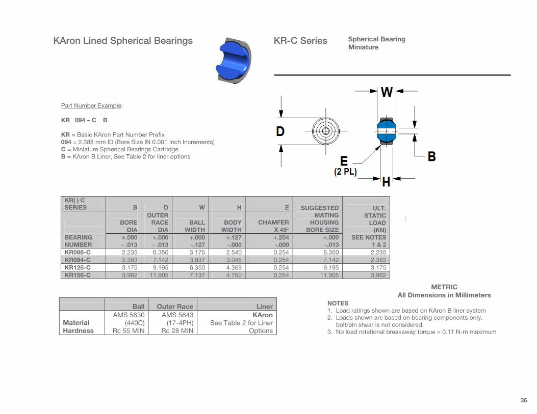
36
:
KR( ) C SERIES B D W H E
SUGGESTED
MATING HOUSING
BORE SIZE
ULT.
STATIC LOAD
(KN) SEE NOTES
1 & 2
BEARING NUMBER
BORE
DIA
OUTER RACE
DIA
BALL
WIDTH
BODY
WIDTH
CHAMFER
X 45° +.000 - .013
+.000 - .013
+.000 -.127
+.127 -.000
+.254 -.000
+.000 -.013
KR088-C 2.235 6.350 3.175 2.540 0.254 6.350 2.235 KR094-C 2.383 7.142 3.937 3.048 0.254 7.142 2.383 KR125-C 3.175 9.195 6.350 4.369 0.254 9.195 3.175 KR156-C 3.962 11.905 7.137 4.750 0.254 11.905 3.962
Ball Outer Race Liner
Material Hardness
AMS 5630 (440C)
Rc 55 MIN
AMS 5643 (17-4PH)
Rc 28 MIN
KAron See Table 2 for Liner
Options
NOTES 1. Load ratings shown are based on KAron B liner system 2. Loads shown are based on bearing components only, bolt/pin shear is not considered. 3. No load rotational breakaway torque = 0.11 N-m maximum
METRIC All Dimensions in Millimeters
Part Number Example: KR 094 – C B KR = Basic KAron Part Number Prefix 094 = 2.388 mm ID (Bore Size IN 0.001 Inch Increments) C = Miniature Spherical Bearings Cartridge B = KAron B Liner, See Table 2 for liner options
Spherical Bearing Miniature
KAron Lined Spherical Bearings KR-C Series

37
Ball Race Liner Body Designation
Material Hardness
AMS 5630 (440C)
Rc 55 MIN
AMS 5643 (17-4PH)
Rc 28 MIN
KAron See Table 2
for Liner Options
AMS 5643 (17-4PH)
Rc 39 MIN PASSIVATED
Add Suffix S
TO P/N FOR 17-4PH
Material Hardness
AMS 5630 (440C)
Rc 55 MIN
AMS 5643 (17-4PH)
Rc 28 MIN
KAron See Table 2
for Liner Options
4340 OR 4230 ALLOY STEEL
Rc 39 MIN CAD. PLATED
Add Suffix A
TO P/N FOR ALLOY STEEL
Bearing Size
No Load Rotational
Breakaway Torque
(N-m) 3 & 4 0.06 to 0.68 5 TO 12 0.11 to 1.69 14 TO 16 0.11 to 2.71
M81935/2 SIZE B D L E F N W H O G C R Q° S J
LOAD RATINGS (KN) See Note 1
WEIGHT MAX (KG)
BEARING NUMBER
BORE
DIA
ROD END DIA.
THREAD LENGTH
MIN
THREAD
SIZE
BODY
LENGTH
SHANK
DIA
BALL
WIDTH
BODY
WIDTH
MIN BALL FLAT
+.254 -.254
+.254 -1.575
+.051 -.254
MIN
REF DIA OR
DISTANCE ACROSS
CORNERS
MAX
HOUSING ID
ULT.
STATIC
FATIGUE
AXIAL
PROOF +.000 - .013
+.254 -.254
+.254 -.254
+.254 -.254
+.000 -.051
+.127 -.127
KR3-F 4.826 20.472 19.050 5/16-24 34.925 10.719 11.100 8.560 7.620 9.525 4.775 11.100 15 12.700 15.875 10.5 6.5 4.4 0.036 KR4-F 6.350 20.472 19.050 5/16-24 37.313 10.719 11.100 8.560 7.620 9.525 4.775 11.100 15 12.700 15.875 21.6 10.6 4.4 0.038 KR5-F 7.938 22.860 22.225 3/8-24 41.275 12.319 11.100 8.306 9.144 11.100 6.350 12.700 14 14.732 17.463 31.9 13.4 4.9 0.046 KR6-F 9.525 26.035 25.400 3/8-24 46.025 13.894 12.700 10.566 11.836 11.100 6.350 14.275 8 16.764 20.638 38.0 15.9 7.4 0.073 KR7-F 11.113 29.210 28.575 7/16-20 50.800 15.494 14.275 11.481 13.640 12.700 6.350 15.875 10 18.288 23.017 53.4 21.4 8.2 0.096 KR8-F 12.700 33.960 31.750 1/2-20 57.150 18.669 15.875 13.081 15.418 14.275 6.350 19.050 9 22.606 25.400 86.7 36.7 9.1 0.147 KR10-F 15.875 38.735 34.925 5/8-18 63.500 21.844 19.050 14.656 18.974 17.450 9.525 22.225 12 25.908 30.163 97.4 40.8 10.8 0.218 KR12-F 19.050 45.085 41.275 3/4- 16 73.025 25.019 22.225 16.256 21.463 20.625 9.525 25.400 13 29.464 34.925 130.3 51.6 12.5 0.305 KR14-F 22.225 51.435 47.625 7/8-14 85.725 28.194 22.225 19.431 25.273 23.800 12.700 28.575 6 33.020 41.275 153.5 58.3 14.8 0.435 KR16-F 25.400 70.485 53.975 1 1/4 -12 104.775 42.875 34.925 25.781 32.233 33.325 14.300 44.450 12 51.308 53.975 357.2 135.2 19.3 1.232
METRIC All Dimensions in Millimeters
Part Number Example: KR 6 - F S B L K KR = Basic Rod End Part Number Prefix 6 = 9.525 mm ID (ID in 1/16 increments) F = Female Rod End Body S = Rod End Body Material, “S” or “A” B = KAron B liner (See Table 2 for liner options) L = “L” for Left Hand Thread K = “K” for Keyway
Note 1: Load ratings shown are based on KAron B liner system
Rod End, Female Dimensionally Equivalent to Mil-B-81935/2
KAron Lined Rod End Bearings KR-F Series

38
NOTE 1: Load ratings shown are based on KAron B liner system
M81935/1 SIZE B D L E F W H O G Q° J
LOAD RATINGS (KN) See Note 1
WEIGHT MAX (KG)
BEARING NUMBER
BORE
DIA
ROD END DIA.
THREAD LENGTH
MIN
THREAD
SIZE
BODY
LENGTH
BALL
WIDTH
BODY
WIDTH
MIN BALL FLAT
KEYWAY
FLAT
MIN
MAX
HOUSING ID
ULT.
STATIC
FATIGUE
AXIAL
PROOF +.000 - .013
+.254 -.254
+.254 -.254
+.000 -.051
+.127 -.127
+.000 -.508
KR3-M 4.826 20.472 24.587 5/16-24 39.675 11.100 8.560 7.620 24.892 15 15.875 10.5 6.5 4.4 0.036 KR4-M 6.350 20.472 24.587 5/16-24 39.675 11.100 8.560 7.620 24.892 15 15.875 21.6 10.6 4.4 0.038 KR5-M 7.938 22.860 30.150 5/16-24 47.625 11.100 8.306 9.144 32.258 14 17.463 31.9 13.4 4.9 0.046 KR6-M 9.525 26.035 30.150 3/8-24 49.225 12.700 10.566 11.836 31.369 8 20.638 38.0 15.9 7.4 0.073 KR7-M 11.113 29.210 32.537 7/16-20 53.975 14.275 11.481 13.640 35.611 10 23.017 53.4 21.4 8.2 0.096 KR8-M 12.700 33.960 37.287 1/2-20 61.925 15.875 13.081 15.418 40.361 9 25.400 86.7 36.7 9.1 0.147 KR10-M 15.875 38.735 39.675 5/8-18 66.675 19.050 14.656 18.974 42.748 12 30.163 97.4 40.8 10.8 0.218 KR12-M 19.050 45.085 42.850 3/4- 16 73.025 22.225 16.256 21.463 45.923 13 34.925 130.3 51.6 12.5 0.305 KR14-M 22.225 51.435 50.800 7/8-14 85.725 22.225 19.431 25.273 53.873 6 41.275 153.5 58.3 14.8 0.435 KR16-M 25.400 70.485 59.512 1 1/4 -12 104.775 34.925 25.781 32.233 62.586 12 53.975 357.2 135.2 19.3 1.232
Ball Race Liner Body Designation
Material Hardness
AMS 5630 (440C)
Rc 55 MIN
AMS 5643 (17-4PH)
Rc 28 MIN
KAron See Table 2 for Liner Options
AMS 5643 (17-4PH)
Rc 39 MIN PASSIVATED
ADD SUFFIX S TO P/N FOR
17-4PH
Material Hardness
AMS 5630 (440C)
Rc 55 MIN
AMS 5643 (17-4PH)
Rc 28 MIN
KAron See Table 2 for Liner Options
4340 OR 4230 ALLOY STEEL
Rc 39 MIN CAD. PLATED
ADD SUFFIX A TO P/N FOR
ALLOY STEEL
BEARING SIZE
No Load Rotational
Breakaway Torque
(N-m) 3 & 4 0.06 to 0.68 5 TO 12 0.11 to 1.69 14 TO 16 0.11 to 2.71
METRIC All Dimensions in Millimeters
Part Number Example: KR 6 - M S B L K KR = Basic Rod End Part Number Prefix 6 = 9.525 ID (ID in 1/16 increments) M = Male Rod End Body S = Rod End Body Material, “S” or “A” B = KAron B liner (See Table 2 for liner options) L = “L” for Left Hand Thread K = “K” for Keyway
Rod End, Male Dimensionally Equivalent to Mil-B-81935/1
KAron Lined Rod End Bearings KR-M Series

39
:
KR( ) FS SERIES B D L E F N W H S ULT.
STATIC LOAD
(KN) SEE NOTES
1 & 2
BEARING NUMBER
BORE
DIA
ROD END DIA.
THREAD LENGTH
THREAD
SIZE UNF-3B
BODY
LENGTH
SHANK
DIA
BALL
WIDTH
BODY
WIDTH
REF DIA OR
DISTANCE ACROSS
CORNERS +.000 - .013
+.254 -.254
+.788 -.788
+.254 -.254
+.254 -.254
+.000 -.127
+.127 -.127
KR047-FS 1.191 4.801 5.385 0-80 9.068 3.962 2.769 2.083 5.080 1.0 KR094-FS 2.383 6.350 6.604 3-56 12.471 4.750 3.175 2.134 5.842 1.8 KR125-FS 3.175 11.913 12.700 6-32 23.800 5.537 6.350 4.750 6.680 3.8 KR156-FS 3.962 14.275 15.875 8-32 28.575 6.350 7.137 5.563 7.493 4.7
Ball Rod End Body Liner
Material Hardness
AMS 5630 (440C)
Rc 55 MIN
AMS 5643 (17-4PH)
Rc 28 MIN
KAron See Table 2 for Liner
Options
NOTES 1. Load ratings shown are based on KAron B liner system 2. Loads shown are based on bearing components only, bolt/pin shear is not considered. 3. No load rotational breakaway torque = 0.11N-m maximum
METRIC All Dimensions in Millimeters
Part Number Example: KR 094 – FS B L K KR = Basic KAron Part Number Prefix 094 = 2.388 mm ID, Bore Size In 0.001 Inch Increments FS = Miniature Female Rod End Body B = KAron B Liner, See Table 2 For Liner Options L = Left Hand Thread Option K = Keyway Option
Rod End, Female Miniature
KAron Lined Rod End Bearings KR-FS Series

40
:
KR( ) FM SERIES B D G E F W H ULT.
STATIC LOAD
(KN) SEE NOTES
1 & 2
BEARING NUMBER
BORE
DIA
ROD END DIA.
THREAD LENGTH
THREAD
SIZE UNF-3A
BODY
LENGTH
BALL
WIDTH
BODY
WIDTH +.000 - .013
+.254 -.254
+.788 -.788
+.254 -.254
+.000 -.127
+.127 -.127
KR047-MS 1.191 4.801 5.385 0-80 9.068 2.769 2.083 1.0 KR094-MS 2.383 6.350 6.604 3-56 12.471 3.175 2.134 1.8 KR125-MS 3.175 11.913 12.700 6-32 23.800 6.350 4.750 3.8 KR156-MS 3.962 14.275 15.875 8-32 28.575 7.137 5.563 4.7
Ball Rod End Body Liner
Material Hardness
AMS 5630 (440C)
Rc 55 MIN
AMS 5643 (17-4PH)
Rc 28 MIN
KAron See Table 2 for Liner
Options
NOTES 1. Load ratings shown are based on KAron B liner system. 2. Loads shown are based on bearing components only, bolt/pin shear is not considered. 3. No load rotational breakaway torque = 0.11 N-m maximum
METRIC All Dimensions in Millimeters
Part Number Example: KR 094 – MS B L K KR = Basic KAron Part Number Prefix 094 = 2.388 mm ID, Bore Size In 0.001 Inch Increments MS = Miniature Male Rod End Body B = KAron B Liner, See Table 2 For Liner Options L = Left Hand Thread Option K = Keyway Option
Rod End, Male Miniature
KAron Lined Rod End Bearings KR-MS Series

41
M81934/1 B D T .254
O’SIZE DIA D
U .508
O’SIZE DIA D
L WEIGHT
LBS/INCH (REF)
BEARING NUMBER
BORE
DIA
OUTER
DIA.
Mil Spec Length Limits
(Suggested) + .000
- .0254 See
NOTE 1 See
NOTE 1 See
NOTE 1
MIN
MAX
AL
CRES KRJ4 6.388 9.550 9.804 10.058 008 014 .006 .017 KRJ5 7.976 11.140 11.349 11.603 008 018 .008 .022 KRJ6 9.563 12.730 12.984 13.238 008 022 .009 .025 KRJ7 11.151 14.321 14.575 14.829 008 028 .010 .028 KRJ8 12.738 15.913 16.167 16.421 008 028 .011 .031 KRJ9 14.326 17.506 17.760 18.014 008 036 .013 .036 KRJ10 15.913 20.681 20.935 21.189 008 044 .022 .061 KRJ11 17.501 22.268 22.522 22.776 008 052 .023 .064 KRJ12 19.088 23.858 24.112 24.366 008 052 .025 .070 KRJ14 22.263 27.038 27.292 27.546 008 052 .029 .080 KRJ16 25.438 30.221 30.475 30.729 008 060 .033 .091 KRJ18 28.613 33.396 33.650 33.904 010 060 .037 .101 KRJ20 31.788 36.571 36.825 37.079 012 068 .040 .111 KRJ22 34.963 39.746 40.000 40.254 012 068 .044 .122 KRJ24 38.138 44.508 44.762 45.016 012 088 .065 .179 KRJ26 41.313 47.683 47.937 48.191 016 096 .070 .193 KRJ28 44.488 50.858 51.112 51.366 016 096 .075 .207 KRJ32 50.838 57.208 57.462 57.716 016 096 .085 .234
LENGTH SUFFIX
CODE
LENGTH +.000 -.254
CODE
LENGTH +.000 -.254
-008 6.350 -048 38.100 -009 7.137 -050 39.675 -010 7.925 -052 41.275 -011 8.738 -054 42.850 -012 9.525 -056 44.450 -014 11.100 -058 46.025 -016 12.700 -060 47.625 -018 14.275 -062 49.200 -020 15.875 -064 50.800 -022 17.450 -066 52.375 -024 19.050 -068 53.975 -026 20.625 -070 55.550 -028 22.225 -072 57.150 -030 23.800 -074 58.725 -032 25.400 -076 60.325 -034 26.975 -078 61.900 -036 28.575 -080 63.500 -038 30.150 -082 65.075 -040 31.750 -084 66.675 -042 33.325 -086 68.250 -044 34.925 -088 69.850 -046 36.500 -096 76.200 Bearing Materials
Material Condition Surface Finish
P/N Symbol
Outer Housing
AMS 5643
17-4PH CRES
H1150
Passivate Per QQ-P-35
Or Cad Plate Per QQ-P-416
S QQ-A-200/3 Or
QQ-A-225/6 2024 Aluminum
T851/T8511
Anodize Per MIL-A-8625 TYPE I Or II Or Chem Film
Per MIL-C-5541
Y Liner
KAron
N/A
N/A
See Table 2 for Liner Options
METRIC - All Dimensions in Millimeters
Part Number Example: KRJ 8 – S B C - 032 - L T KRJ = Basic Journal Part Number Prefix 8 = 12.700 mm ID (ID in 1/16 Inch Increments) S = “S” for 17-4PH CRES Outer Housing (“Y” for Aluminum) B = KAron B Liner, See Table 2 For Liner Options C = “C” for Cad Plate Per QQ-P-416 Type II CL 2 (For 17-4PH Only) 032 = 25.400 mm Long (Length in 1/32 Inch Increments) L = “L” for .010± .001 Undersized “B” Diameter for Reaming at Assy T = Add “T” for .010 or “U” for .020 Oversize DIA “D”
NOTES 1: TOLERANCE: CRES (“S”) = +.0000, -.0005 ALUMINUM (“Y”) = +.0005, -.0005 2. FOR LOAD RATINGS SEE PAGE XXX 3. ALUMINUM BEARINGS ANODIZED PER MIL-A 8625 OR CHEM FILM PER MIL-C-5541 4 ADD THIS WEIGHT TO JOURNAL WEIGHT ON PAGE XXX
Sleeve, Non-Flanged, Lined Bore Qualified to SAE AS81934/1 with KAron B Mil-B-8943 with KAron V, M, and RP
KAron Lined Journal Bearings KRJ Series

42
LENGTH SUFFIX
CODE
LENGTH +.000 -.254
CODE
LENGTH +.000 -.254
-008 6.350 -048 38.100 -009 7.137 -050 39.675 -010 7.925 -052 41.275 -011 8.738 -054 42.850 -012 9.525 -056 44.450 -014 11.100 -058 46.025 -016 12.700 -060 47.625 -018 14.275 -062 49.200 -020 15.875 -064 50.800 -022 17.450 -066 52.375 -024 19.050 -068 53.975 -026 20.625 -070 55.550 -028 22.225 -072 57.150 -030 23.800 -074 58.725 -032 25.400 -076 60.325 -034 26.975 -078 61.900 -036 28.575 -080 63.500 -038 30.150 -082 65.075 -040 31.750 -084 66.675 -042 33.325 -086 68.250 -044 34.925 -088 69.850 -046 36.500 -096 76.200
M81934/2 B D H F T .254
O’SIZE DIA D
U .508
O’SIZE DIA D
L FLANGE WEIGHT
LBS (REF) NOTE 2
BEARING NUMBER
BORE
DIA
OUTER
DIA.
FLANGE
DIA
FLANGE
WIDTH
Mil Spec Length Limits
(Suggested) + .000
- .0254 See
NOTE 1 +.000 -.508
+.000 -.127
See NOTE 1
See NOTE 1
MIN
MAX
AL
CRES
KRJ4-UD 6.388 9.550 19.050 9.804 10.058 008 014 .003 .007 KRJ5-UD 7.976 11.140 20.625 11.349 11.603 008 018 .003 .007 KRJ6-UD 9.563 12.730 22.225 12.984 13.238 008 022 .003 .007 KRJ7-UD 11.151 14.321 23.800 14.575 14.829 008 028 .013 .008 KRJ8-UD 12.738 15.913 25.400 16.167 16.421 008 028 .004 .010 KRJ9-UD 14.326 17.506 28.575 1,588 17.760 18.014 008 036 .004 .011 KRJ10-UD 15.913 20.681 31.750 20.935 21.189 008 044 .005 .014 KRJ11-UD 17.501 22.268 34.925 22.522 22.776 008 052 .007 .020 KRJ12-UD 19.088 23.858 38.100 24.112 24.366 008 052 .009 .023 KRJ14-UD 22.263 27.038 41.275 27.292 27.546 008 052 .009 .025 KRJ16-UD 25.438 30.221 44.450 30.475 30.729 008 060 .010 .027 KRJ18-UD 28.613 33.396 47.625 33.650 33.904 010 060 .014 .041 KRJ20-UD 31.788 36.571 50.800 36.825 37.079 012 068 .018 .050 KRJ22-UD 34.963 39.746 53.975 40.000 40.254 012 068 .019 .053 KRJ24-UD 38.138 44.508 57.150 2.380 44.762 45.016 012 088 .019 .054 KRJ26-UD 41.313 47.683 60.325 47.937 48.191 016 096 .020 .056 KRJ28-UD 44.488 50.858 63.500 51.112 51.366 016 096 .023 .064 KRJ32-UD 50.838 57.208 69.850 57.462 57.716 016 096 .026 .072
Bearing Materials
Material Condition Surface Finish
P/N Symbol
Outer Housing
AMS 5643
17-4PH CRES
H1150
Passivate Per QQ-P-35
Or Cad Plate Per QQ-P-416
S QQ-A-200/3 Or
QQ-A-225/6 2024 Aluminum
T851/T8511
Anodize Per MIL-A-8625 TYPE I Or II Or Chem Film
Per MIL-C-5541
Y Liner
KAron
N/A
N/A
See Table 2 for Liner Options
METRIC - All Dimensions in Millimeters
Part Number Example: KRJ 8 – U D S B C - 032 - L T KRJ = Basic Journal Part Number Prefix 8 = 12.700 mm ID (ID in 1/16 Inch Increments) U = “U” Designates Flanged Journal Bearing D = “D” for KAron Lined Flange S = “S” for 17-4PH CRES Outer Housing (“Y” for Aluminum) B = KAron B Liner, See Table 2 For Liner Options C = “C” for Cad Plate Per QQ-P-416 Type II CL 2 (For 17-4PH Only) 032 = 25.400 mm Long (Length in 1/32 Inch Increments) L = “L” for .010± .001 Undersized “B” Diameter for Reaming at Assy T = Add “T” for .010 or “U” for .020 Oversize DIA “D”
NOTES 1: TOLERANCE: CRES (“S”) = +.0000, -.0005 ALUMINUM (“Y”) = +.0005, -.0005 2. FOR LOAD RATINGS SEE PAGE XXX 3. ALUMINUM BEARINGS ANODIZED PER MIL-A 8625 OR CHEM FILM PER MIL-C-5541 4 ADD THIS WEIGHT TO JOURNAL WEIGHT ON PAGE XXX
Sleeve, Flanged, Lined Bore (Optional Lined Flange) Qualified to SAE AS81934/2 with KAron B Mil-B-8943 with KAron V, M, and RP
KAron Lined Journal Bearings KRJ-U(D) Series