karumanchi sravanthi cs 458 exam 2s.web.umkc.edu/ssk7bd/cs458exam2.pdf · cs 458 exam 2 due date:...
TRANSCRIPT

Karumanchi Sravanthi CS 458 Exam 2
Due Date: 12/06/2001

Question #1 We often think of maintenance as an activity directed towards repairing and improving code. Discuss why it is MORE critical to maintain the functional specification and how that can be practically accomplished. Answer #1 The production of the functional specification is the most import stage in the design of any system. It details the solution to be provided to meet the users requirements. It should be approved by the user and should form the basis of the design for both Hardware and Software. A well written functional specification can remove all the surprises when the system is installed. As all the functions, operator interactions control and sequencing associated with the system are clearly detailed. This allows the user to confirm, before the system is developed that the proposed solution fully meets the requirements. The functional specification provides the basis of the design of the system and is used to verify and validate the system during testing, ensuring all the required functions are present and that that they operate correctly. The overall objective is to move from a specification that captures the essence of a problem to a specification that provides substantial implementation details. Formalizing the user's requirements can be a painstaking task. Even if the (human) specifier perfectly understands what the customer actually wants, he or she is not safe from committing specification errors, which may have a major impact on the properties of the very system formalized. Function specification consists of requirements and also functionality of the system. The requirements spec contains the synthesis of the information. It should contain enough information to guarantee the success of the continued design process by specifying the information that is necessary to design a system that solves the situation of concern identified. There is some essential information it should contain. It should specify in detail the functionality the system should provide and mention the users of specific functionality in the system. Besides guiding the designer, this helps define the users' areas of responsibility for new tasks the system create. This together with a specification of the form of solution chosen for the implementation constitutes the definition of the usable functional form of the system. In addition it should set concrete performance targets in terms of e.g. ease of learning and speed of performance. As an example, the amount of training necessary to achieve a certain performance level might be stated, the performance level being defined by the time it takes for the user to perform a certain task and the amount of training being specified in hours. This could be done in requirement spec also. The requirements definition has to be valid, i.e. any system that meets it should be guaranteed to be a system that solves the situation of concern. It should therefore in principle be possible to hand it over to a systems designer that is then able to produce a good system by just sticking to the requirements. Another role is to serve for verification of the actual implementation. This is of special importance when a subcontractor is developing the system where it will be the specification of what the contractor is to deliver.

First the process starts with the product requirement specification, which is based on the user and his requirements of the product. Once the requirement spec is provided the need arises to design each function of the system. The code designer looks at the function specification and then puts down the code to implement the function that is required. The product is designed and when tested, if we find that it does not satisfy the function specified we need to make changes as customer satisfaction is the primary concern. The function specification basically defines what the product does and what it can do. Thus maintain of the function specification is very necessary as it deals with the requirements given by the user and it describes what the system has to do and perform. The requirements definition specifies how the system should support the user's activities and provides a design strategy for how the system should be built. Since function specification specifies in detail the functionality of the system, provide and mention the users of specific functionality in the system, it is really very critical to maintain the spec. Besides guiding the designer, this helps define the users' areas of responsibility for new tasks the system create. This together with a specification of the form of solution chosen for the implementation constitutes the definition of the usable functional form of the system. Thus any changes requested by the user needs to be maintained properly in the function specification. Since the base of the design comes from requirement and function spec maintaining function spec is very critical.
From the above figure we can see that specification is a very important part of the entire development process and since functional specification gives the details of the way the system works it is critical to maintain the functional specification. Documentation is a key criterion.

In order to maintain the function specification the following steps are required
� Changes are inevitable in the system for example a user may request changes or the system may not perform the required function. This gives rise to a need to make changes in the code. These changes need to be put back in the required documents so that the documentation is up to date. The changes may need to be made to the design and function specification.
� The functions need to be very well defined. The functions must be as small and exclusive so that they are kind of independent.
� The interfaces must be very well defined for the designers so that we do not find that this does not work after the final steps and need to make changes.
� Changes made to one function must not affect the other function. � When a new person is hired he must be told about the function specification
describing the functions of the system � The function specification must be very easily readable. � The naming conventions and words used must be readable and known to everyone � It must define the functions of each block and specify what is the input and what
is the output required. For example The primary purpose of TRACS is to simulate the functionality of an ATM. Users may use the system to access their banking accounts, make withdrawals, deposits, or simply inquire about their accounts. Additionally, authorized ATM Managers may access the system to replenish available ATM funds and receive a printout of the ATM log.

Check Available Funds Descr iption:� This function determines the current situation of available funds within the
ATM. �Input:� Current_Num_of_Denominations �Processing:� This function uses the information from Current_Num_of_Denominations
to determine the available funds in the ATM and signals Low_Funds to the bank system if a deficiency is discovered. �
Output:� Low_Funds (to bank system) � Choose Account Descr iption:� This function allows the user to choose the account to access. The user may
access savings or checking accounts. �Input:� Menu_Choice (from user), Account_Information (from bank system),
Account_Status (from bank system) �Processing:� The function displays the possible customer account choices (Savings,
Checking, or Exit) and accepts input from the user. If the user chooses Exit, the user is returned to the screen for choosing transactions. If the user chooses either Savings or Checking, the bank system is contacted to determine if the user has such an account. If he does not, the user is informed of this and TRACS returns to its previous state (displaying the Transaction Menu). If the user does have such an account, the bank account information is stored in Account_Information. �
Output:� Account Menu (to screen), Account_Information (to bank system), Account_Information �
Choose Transaction Descr iption:� This function allows the user to choose the transaction to perform. The user
may perform the following transactions: make a deposit, make a withdrawal, make an account inquiry, or exit. �
Input:� Menu_Choice (from user) �Processing:� The function displays the possible user choices (Make a Deposit, Make a
Withdrawal, Make an Account Inquiry, or Exit) and accepts input from the user. If the user chooses Exit, the function resets TRACS to its initial state (displaying the Verify User Screen). If the user chooses any of the other options, the function stores the choice in Transaction. �
Output:� Transaction Menu (to screen), Transaction � Determine Denominations Descr iption:� This function determines the number of bills of each denomination to give
to the user. �Input:� Current_Num_of_Denominations, Transaction_Amount �Processing:� The function uses the information from the
Current_Num_of_Denominations and the Transaction_Amount to determine the appropriate distribution of money to the user. It then modifies the Current_Num_of_Denominations to reflect its calculations. �
Output:� Current_Num_of_Denominations �

Display Account Information Descr iption:� This function displays the user's account information. �Input:� Account_Information, Menu_Choice (from user) �Processing:� The function accesses the information in Account_Information and
displays it to the screen. It also displays a menu of customer choices (Exit or Print Receipt) and accepts the user's choice as input. If the user chooses Exit, the function resets TRACS to its initial state (displaying the Verify User Screen). If the user chooses Print Receipt, a receipt of the customer's transaction is printed. �
Output:� Account_Information (to screen), Printed Receipt (optional) � Display Aler t Descr iption:� This function displays error messages or alert messages to the user when
necessary. �Input:� Error_Type, Menu_Choice (from user) �Processing:� This function determines a course of action dependent on the information it
receives from Error_Type. In general, it will display text corresponding to the specific error type and then display "Press a key to continue." The function then waits for the user to press a key before exiting. �
Output:� Appropriate Message (to screen) � Make Deposit Descr iption:� This function processes a user's request to make a deposit. It displays the
nstructions for making a deposit to the user. �Input:� Transaction_Amount (from user), Account_Information, Account_Status
(from bank system) �Processing:� The function asks the user for the amount that he will be depositing, stores
this information in Transaction_Amount, displays the instructions for making a deposit (i.e., the user should take an envelope, place the money inside, and place it within the ATM's deposit slot), and warns the user that the transaction is pending. The function also records this transaction in the ATM log and informs the bank system of the deposit. An actual ATM machine instead of the TRACS simulation would also record account information on the inserted deposit envelope in this function. �
Output:� Deposit Instructions (to screen), Transaction_Amount (to bank system), Account_Information (to bank system), Log_Information (to ATM log), Account_Information �
Make Withdrawal Descr iption:� This function processes a user's request to make a withdrawal. �Input:� �Transaction_Amount (from user), Account_Information, Account_Status
(from bank system) �Processing:� The function asks the user for the withdrawal amount and stores this
amount in Transaction_Amount. It then contacts the bank system and verifies that the withdrawal can be processed. If it cannot be processed, the user is informed of this and returned to the Transaction Menu. If the
withdrawal can be processed, the Transaction_Amount is deducted from the user's account by the bank system, the denominations of the withdrawn money are calculated, and the account information is displayed. The function also records this transaction in the ATM log. An actual ATM machine instead of the TRACS simulation would also eject the customer's money in this function. �
Output:� Appropriate Messages (to screen), Transaction_Amount (to bank system), Account_Information (to bank system), Log_Information (to ATM log), Account_Information �
Pr int Account Information Descr iption:� This function prints the user's current account information. �Input:� Account_Information �Processing:� The function reads the information contained in Account_Information and
prints it using the attached printer. �Output:� Printed Receipt � Pr int Log Descr iption:� This function prints the log information for the ATM Manager to review. �Input:� Log_Information �Processing:� This function reads the information contained in Log_Information and
prints it using the attached printer. This function also erases the previous log. �
Output:� Printed Log � Process Bank Request Descr iption:� This function sends a request for information and processing to the bank
computer system and receives the bank's reply. �Input:� Account_Information, Transaction_Amount, Low_Funds, Account_Status
(from bank system) �Processing:� The function sends Account_Information, Transaction_Amount, and
Low_Funds to the bank computer system. When the bank's reply is received, the status of the request is stored in Account_Status and any needed alterations to Account_Information are made. �
Output:� Account_Status, Account_Information, Account_Information (to bank system), Low_Funds (to bank system), Transaction_Amount (to bank system) �
Process Inquiry Descr iption:� This function processes the user's request for an account inquiry. �Input:� Account_Information �Processing:� The function makes a bank request for information and displays the
account information to the user. The function also records this transaction in the ATM log. �
Output:� Account_Information (to screen), Log_Information (to ATM log) �

Process Time-Out Descr iption:� This function causes an error message to occur because of a delayed
amount of time for any user input. �Input:� Time_In, Time �Processing:� This function uses the information from current Time and the Time_In to
determine if a lapse of 30 seconds has occurred between prompted input messages and user input keystrokes. Should such a lapse occur, control is returned to the Verify User Screen. �
Output:� None � Reduce Available Funds Descr iption:� This function reduces the available funds in the ATM whenever a
withdrawal has been processed. �Input:� Transaction_Amount, Current_Num_of_Denominations �Processing:� This function uses the information from the
Current_Num_of_Denominations and the Transaction_Amount to reduce the available funds in the ATM. �
Output:� Current_Num_of_Denominations � Replenish Funds Descr iption:� This function prompts the ATM Manager for the amounts of the three
denominations and for the total amount that the ATM would receive. �Input:� Denominations_Amount (from user), Replenish_Amount (from user) �Processing:� This function uses the ATM Manager's input and stores the values in the
variables Denominations_Amount and Replenish_Amount. The function then uses this information to determine the current status of funds in the ATM. This function prompts the ATM Manager for the amounts of the three denominations and for the total amount that the ATM would receive. The function also updates the value of Current_Num_of_Denominations in order to maintain control of the current ATM funds. �
Output:� Current_Num_of_Denominations � Set Timer ��
Descr iption:� This function simulates a timer for the purposes of causing a time-out if necessary. �
Input:� Time �Processing:� This function creates a time-stamp on all transactions. �Output:� Time_In � Update Log Descr iption:� This function processes an update of the transaction log. �Input:� Account_Number, Account_Status, ATM_ID, Date, Login_Attempts,
Name, Time, Transaction, Erase_Log �Processing:� This function uses the information from the current instances of
Account_Number, Account_Status, ATM_ID, Date, Login_Attempts, Name, Time, and Transaction in order to add this information to

Log_Information and keep the log current. If the value of Erase_Log is true, then this function will erase all transactions in the log. �
Output:� Log_Information (to ATM log) � Ver ify User Descr iption:� This function will act as a welcome screen and will allow the user to access
his account information and perform transactions using the ATM. �Input:� Account_Number (from user), PIN (from user), Account_Information
(from bank system), Menu_Choice (from ATM Manager) �Processing:� This function prompts the user for his account number and PIN. It then
stores these values in the variables Account_Number and PIN. The Account_Number and PIN is verified with the bank system. If the identified PIN matches the one for the given account number, the customer proceeds to the Transaction Menu. If the identified PIN does not match, then the user will be prompted to re-enter the PIN number. A user may continue in this fashion until five attempts have been made, at which time, the system returns to the Verify User screen. The function also records the login attempt in the ATM log. If the identified PIN is that of the authorized ATM Manager, then the function displays the possible ATM Manager choices (Print Log, Replenish Funds, or Exit) and accepts input from the ATM Manager. If the ATM Manager chooses Exit, the system returns to the Verify User Screen. Once the user has been verified, the account information is stored in Account_Information. �
Output:� Account_Information, Account_Information (to bank system), Log_Information (to ATM log) �
The above is an idea of how a function spec can be. If any change is made to the functionality of the function then it needs to be reflected in the function spec and thus will give an idea to the code designer.
� Some uniform conventions must be used so that they are followed everywhere and it won’ t be confusing.
Question #2 Given the following principle: “ The largest postdesign cost risk for NON software products is manufacture. The largest postdesign cost risk for software products is maintenance. In the former case, design for manufacturability is a major design driver. Unfortunately, design for maintainability is not the standard for software. It should be.” What major changes should be made in the software development life cycle to enable design for maintainability to be implemented? What changes in corporate culture would be necessary to ensure it’s success?
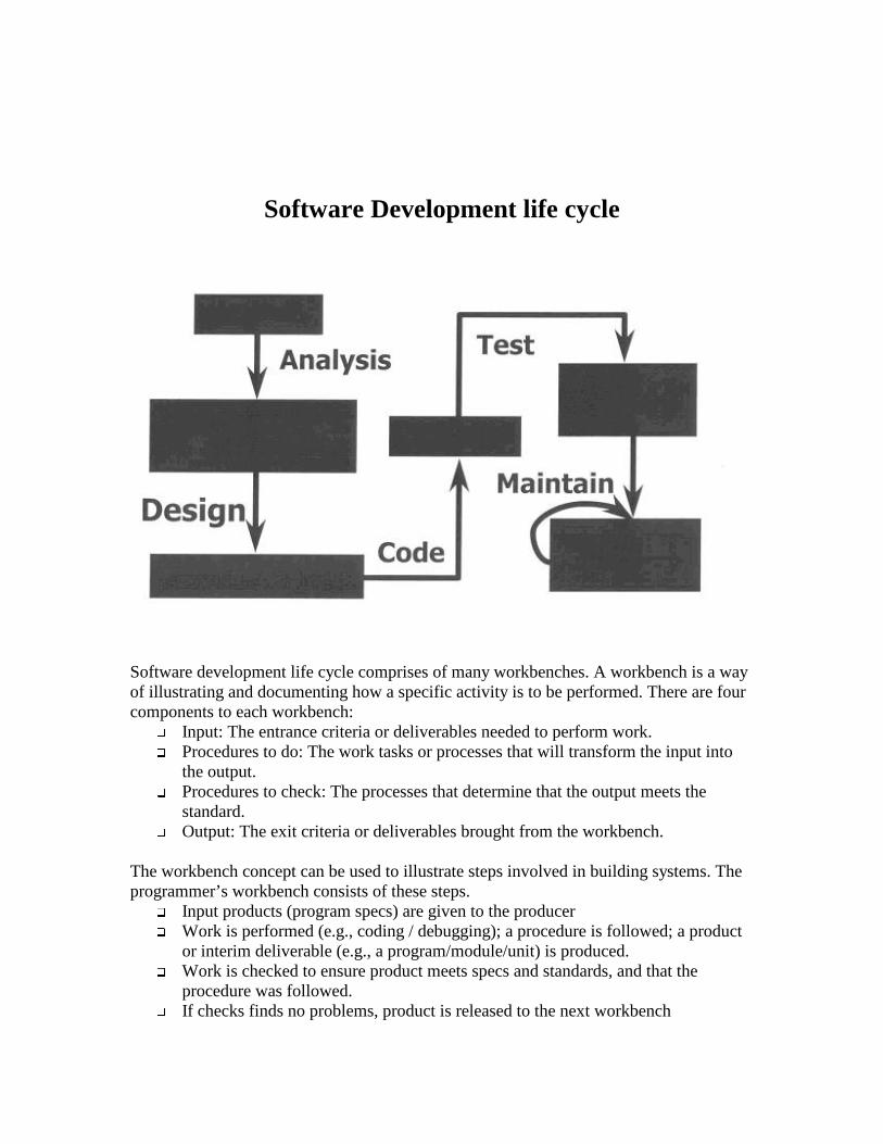
Software Development life cycle
Software development life cycle comprises of many workbenches. A workbench is a way of illustrating and documenting how a specific activity is to be performed. There are four components to each workbench:
� Input: The entrance criteria or deliverables needed to perform work. � Procedures to do: The work tasks or processes that will transform the input into
the output. � Procedures to check: The processes that determine that the output meets the
standard. � Output: The exit criteria or deliverables brought from the workbench.
The workbench concept can be used to illustrate steps involved in building systems. The programmer’s workbench consists of these steps.
� Input products (program specs) are given to the producer � Work is performed (e.g., coding / debugging); a procedure is followed; a product
or interim deliverable (e.g., a program/module/unit) is produced. � Work is checked to ensure product meets specs and standards, and that the
procedure was followed. � If checks finds no problems, product is released to the next workbench

� If checks problems, product is sent back for network. As an example of how a project team would use the workbench to guide them through a project phase, we’ ll describe a sample validation of computer code. The programmer’s unit test consists of these steps:
� Give input products (e.g., program code) to the tester � Perform work (e.g., coding and debugging); follow a procedure; produce a
product or interim deliverable (e.g., the test results) � Check work to ensure test results meet test specs and standards and that the test
procedure was followed � If the check process finds no problems, release the product (i.e., test results) to the
next workbench � If the check process finds problems, send the product back for rework
Software maintenance refers to the actual modification of software and related documentation. This occurs during the final phases of the system life cycle and is often precipitated by:
� Identification of program "bugs" � Demand for additional capabilities/features � Changing functional requirements � Increase/decrease in scope of a system.
Differences between software development and software maintenance � Constraints of an existing system
Changes must conform or be compatible with an existing architecture, design and code constraints.
� Shorter time frames Development spans one or more years. Maintenance spans hours or up to 6 months
� Available test data Software development creates test data from scratch and maintenance uses existing test data with regression testing creating new data for the changes.
� Must work within the constraints of an existing system. Large part of effort is in understanding the change in the context of existing system artifacts
� Impact analysis needed for estimates. Requires an augmentation rather than construction mindset
� Typically changes are smaller scale than original development � Manage change with multiple releases rather than functional builds � The closer development gets to delivery the more it looks like maintenance
The Maintenance Process begins when a user initiates a request for a change. It ends when the system passes testing and is accepted by the user and is released for operation. In between there are many activities that must be planned and coordinated by use of change management.

Software Maintenance Process It is a seven-step approach: Step 1 - Change Management Step 2 - Impact Analysis Step 3 - System Release Planning Step 4 - Design Changes Step 5 - Coding Step 6 - Testing Step 7 - System Release Step 1 - Change Management It uniquely identifies, describes and tracks the status of each requested change. The change requests are recorded and tracked through all stages of the maintenance process in a Change Management Tracking System. Project Management and QA can receive input on the
� Status of the Change Requests � Audit trail changes
Change Request It is a basic tool (manual or electronic) of change management. It documents all information about changes and updates throughout the maintenance process for the following reasons.
� Help manage the system release � For the analysis of the types and frequency of defects � To streamline the process and reduce costs � To communicate to maintainers, managers and clients
Step 2 - Impact Analysis It identifies all systems/system products affected by a change request developing an estimate of the resources needed to accomplish the change. Aims of this step:
� To determine the scope of the requested change for planning and implementation of the change.
� To develop accurate estimates of resources. � To analyze cost/benefits of the change. � To communicate the complexity of the change.
Evaluate Change Requests
� Look for potential impact on existing systems, other systems, documentation, hardware, data structures and humans
� Without analysis of the changes the change may insert defects that are not immediately apparent
Problems associated:
� Documentation doesn’ t exist and must be created.

� Documentation is out of date or incorrect leading to incorrect design decisions. � Documentation doesn’ t exist and must be created. � Documentation is out of date or incorrect leading to incorrect design decisions
Estimate Resources
� Function Point metrics � Static analysis / software metrics
Step 3 - System Release Planning Aims:
� To establish the schedule of system releases � To determine the contents of a system release � System Release/Version Description Document � Describes the contents / timing of a system release � Communicates between maintainers and users � Used by operations to plan hardware, operational procedures and backout
procedures � The method of working changes so that work can be managed like a development
project Unscheduled Releases cause problems with:
� The most important changes may not be done first � Training / documentation may not coincide with the release � Testing of the changes may not be adequate � Implementation may not be planned
Step 4 - Design Changes Aims:
� To develop a revised logical (system level) and physical (program level) design for the change
� Analyze and design the changes � Update the documentation � Update the configuration management system � Update the change request � To design the changes for each of the categories of maintenance
Corrective Maintenance It includes all repairs of defects in an existing system Defects can stem from:
� Requirements specification errors � Design errors � Coding errors
Types of Corrective Maintenance:
� Emergency Repairs

They are usually performed in a short time frame and often focus on a single program.
� Scheduled Repairs It is used to fix defects that do not require immediate attention and also to re-examine all emergency repairs
Adaptive Maintenance Aims: Its main aim is to evolve any system to meet the needs of the user and the business It could be invoked by internal needs, external competition, external requirements e.g. changes in law. It is essentially the same as a new development - use Structured Design At each stage this requires:
� Review of the change request and design the changes � Update the documentation � Conduct a walkthrough � Update Configuration and Change Management
Perfective Maintenance The reason to improve software that works and to improve the quality of working programs is because of the following reasons:
� Costs shrink � Programs become more maintainable � User’s satisfaction leaps � Includes all efforts to polish or refine the quality of the software or the
documentation � Includes re-engineering � Rewriting and upgrading documentation � Restructuring poorly written code � Important that the improvement reduces the system maintenance costs � Important to document a case for quality improvement
Procedure to identify the candidates for change
� Define selection criteria � Gather related data � Analyze the data � Implement a solution � Review the benefits and results derived
Define Selection Cr iter ia
� Defect Type � Defect Costs � Symptoms

� Cause � Failure Rate (MTBF-Mean Time Between Failures) � Failure Type � Field performance � Enhancement Costs � Enhancement Rate
Gather related data
� Change request database � Historical change request � Configuration management system histories � Operating system logs � Time-operating / project management systems
Analyze the data Conduct a Pareto Analysis A Pareto Analysis identifies the 20% of the programs that consume 80% of the budget and personnel resources i.e. 80/20 rule Implement a Solution
� Select the specific qualities to improve � Select a solution to achieve these qualities � Apply problem-solving techniques
Review the benefits and results der ived
� Complete redesign and rewrite � Use when more than 20% of the program changes and when program is being
upgraded to new technology. Do not use this when the design and function of the program is not known and complete restructuring or overhaul of the existing code.
� Use on highly maintenance prone programs � Partial restructuring integrated with adaptive maintenance � Use for orderly improvement with each system release
Retirement of the system and complete redevelopment Use when moving to a new technology and when the costs of maintaining the software and the hardware exceed the cost of re-development Step 5 - Code Aim:
� To clarify existing code and simplify changing it � Re-Engineering Source Code � Restructuring � Redesign
Step 6 - Software Testing Maintenance / Development Differences
For Maintenance: � Only changes need to be reviewed � Only new test cases that exercise the changes need to be developed � Existing and new test cases are required to test the changes � Test results are compared against previous test results (Regression Testing)
Maintenance Testing
� 1/3 planning and design � 1/6 coding � 1/4 component and early system test � 1/4 system test with all components
Easier to test incrementally Data collected during impact analysis identifies what must be tested at each level Step 7 - System Release Aims:
� Package the system for release including: � Documentation � Software � Training � Other products � Hardware � Deliver the system to the user � Install the system release with backup procedures
Changes that need to be made to the software development life cycle: Recently, software products have exhibited a dramatic growth in size, complexity and life cycle cost (LCC). Changes over the life of a program are inevitable, even if the program has met all its design requirements. Software changes are needed to adapt to increased functional requirements and different system configurations brought by these changes. One of the most urgent concerns in the computer industry is the need to maintain and enhance the software product at faster rates and at lower costs. To meet this objective, better, more maintainable software must be designed. Maintainable software, which facilitates the correction of errors and deficiencies, can be expanded or contracted to satisfy new or changing requirements, which may include enhancing existing functions, modifying for hardware upgrades, and correcting code errors. To be able to design maintainability the following changes are required:
� Early planning: anticipating what and how programs might be modified at a later stage.
� Modular design: defining subsets and simplifying functionality (i.e., one module performs only one function).
� Object-oriented design: encapsulating both methods and data structures to achieve a higher level of independence than that of modular design.
� Uniform conventions: facilitating error detection and debugging. � Naming conventions: providing understandable codes. � Coding standards, comments, and style enhancing readability of the program.

� Documentation standards. � Common tool sets. � Configuration Management
Ear ly Planning As with anything else, early planning puts design problems into perspective, provides good strategy, and is the most cost-effective way for modifying or adding features to software products at some later time. Early in the definition phase, expected changes should be identified and prioritized so that their considerations can result in an architecture receptive to change. The system functionality should be decomposed into manageable segments for which software modules may be built. The format of these modules should be standardized so that code can be added, deleted, or modified to incorporate expected as well as unexpected changes. This helps to ensure that minimum interface alterations will be required to implement a change. Also, some particularly volatile should have their parametric values stored databases to facilitate their change. Identifying expected changes early in the definition phase, and making allowances for unexpected changes, makes for a more maintainable software product. Configuration Management Configuration management of software is probably the single most important management and maintainability concept utilized in software development. Utilization of coding standards, documentation standards, release standards, common languages and other methods will provide for good configuration management. A plan should be developed very early in the development cycle for managing the configuration of the software under development, and that plan should be followed rigorously. If configuration management breaks down, the code under development is doomed extremely troublesome when release for operations. Modular Design Modularized software is best structured so that high probability changes do not affect the interface of widely used modules. However, one of the most commonly encountered errors is when two or more simple functions are combined into one module because the function seems too simple to separate. For example, one might be tempted to combine synchronization and message sending and acknowledgment in building an operating system. The two functions seem closely related and for the sake of reliability one may insist on a "handshake" with each exchange of synchronization signals. If later an application is encountered in which synchronization is needed more frequently, it may be found that there is no simple way to strip the message sending routine away from the synchronization routines. Modular design also provides reusable code and reduces redundant coding that might occur in many similar functions. For example, a generic input/output routine will save coding time and make it convenient for users to retrieve and use the module. Moreover, the modules can be saved in a software repository; e.g., FORTRAN, Mat-Lib, and made available to the public. Identifying potentially desirable modules, ever, is a demanding intellectual exercise in

which the software designer first searches for the minimal module that might conceivably perform useful service and then searches for a set of minimal increments to the systems. Each increment is small-sometimes so small that it seems trivial. The minimalist approach seeks to avoid a module that performs more than one function as discussed above. Identifying minimal modules is difficult, however, because minimal system programs are not usually requested. Minimal modules are useful if the software family is going to be developed but are not usually worth by themselves. Similarly, maximum flexibility is obtained by looking for the smallest possible increments in capability. Object Or iented Design Object-Oriented Design is a more recent approach in restructuring programs. It is intended to make program tasks more independent of each other and therefore easier to maintain. Normally, as taught in most computer courses, structured programming helps in dealing with the complexities and reduction of "spaghetti" in the code; however, structured programming is still based on the expected sequence of executing instructions. Attempting to design and debug programs by thinking through the order in which the computer does things ultimately leads to software that nobody can fully understand. With object-oriented techniques, a designer generates code based on objects and their behaviors. Objects, which might be real or abstract, could include an invoice, organization, order-filling process, or icon on a screen that a user points to and opens. An object's behaviors are expressed by its contained data structures and operations, which are also called "methods." Most systems can be built without having to think about loops, branches, and program-control structures, because the object-oriented technique is an event-driven programming approach in which events cause changes in the state of objects. Each state change is usually simple to program by itself, so the program is divided into relatively simple pieces. Each object, in effect, performs a specific function independent of other objects. It responds to messages, not knowing why the message was sent or what the consequences its actions will be. Because objects act individually, each class, which is made up of, these objects can be changed largely independent of other classes. This makes the class relatively easy to test and modify. Object-oriented systems are much easier to maintain than conventional systems. Space and other considerations make it impossible to discuss the object-oriented concept here. Readers to whom this concept is new are encouraged to pursue it further in object-oriented programming. Uniform Conventions Software coding standards and naming conventions are also important in producing maintainable code; therefore, they must be established during the development process. All production of new code should be done according to these standards, along with all

program extension and repair work, during both the development and maintenance phases. All software development processes should be documented, consistent and repeatable. The benefit to the maintenance programmer is that by learning the formal aspects and naming conventions of one segment of the system software, he or she will know these aspects and conventions for the other segments. Error detection and debugging are facilitated with more effort concentrated on understanding the logic of the program, even when working with a new segment. Naming Conventions The naming standards should encompass the systematic assignment of mnemonic terms chosen to suggest their own interpretation by carrying as much information about their respective variables. It would be desirable, from a maintenance programmer's point of view, if there were a one-to-one correspondence between variable names throughout the program system. Global variables should be defined in a common glossary with their names the same in all routines. Local model variables are those having a meaning in the model or system specification but appear only in one routine; names of these may duplicate other local variable names, but not global names. Coding Standards, Comments and Style Since easy-to-read code is a definite plus to the software maintainer, one set of coding standards should be used to develop the documentation, flowchart construction, input/output processing, error processing, module interfacing, and naming of modules and variables. This consistency, which promotes general understanding, has prompted the Government to stipulate in software programming contracts the inclusion of the following software coding:
� Presentation style: describes the rules and conventions for the format of the source code that may include paper listings, listings stored electronic media, or both:
• Indentation and spacing. • Use of capitalization.
� Uniform presentation of information throughout the source code; the grouping of all data declarations.
� Use of headers. � Layout of source code listings. � Conditions under which comments are provided and format to be used. � Size of code aggregates (100-200 executable, nonexpandable statements).
� Naming: defines rules and conventions defined in a common glossary with their names governing the selection of identifiers used in the source code listing. Documentation Standards
The reasoning for documentation standards is nearly identical to that for coding standards. Standardized document formats are necessary for good maintainability. Consistently formatted documentation simplifies the process of familiarization with any

given project and assists the effort to make any given information easier to locate. It also promotes understanding of what the current status of a project is, what changes have been made, and the reasoning behind various activities during the development process. Maintenance should focus on modification of the entire application including documentation and not on the source code modification alone. System documentation problems occur when changes to source code are not reflected in the design documentation or user-oriented manuals.
Whenever a change to data flow, software structure, module procedure, or any other related characteristic is made, supporting technical documentation including security documentation must be updated. System documentation that does not accurately reflect the current state of the software is probably worse than no documentation at all. Major problems occur when innocent use of unchanged system documentation leads to incorrect assessments of software characteristics.
The side effects from documentation shortfalls can be reduced substantially if all applicable documentation is reviewed prior to any further release of the software. In some instances, maintenance requests may require no change in software design or source code, but indicate a lack of clarity in user documentation. In such cases, the maintenance effort should focus on redefining and clarifying existing documentation.
Common Toolsets A uniform environment and a standardized set of adds several points important to increasing the maintainability of software. First, is the ability to reuse validated code. If changes must be made to the software, and the changes are similar to something that has been used previously, it is very convenient to be able to use code that has already been proven with the development tools being utilized. Secondly, a common toolset and environment allow for program and code portability between stations. As the environment is common, no conversions are necessary, and program compilation differences are negated. A standardized environment also reduces time necessary for training. Much less time is necessary to train people on one system than to train them for multiple toolsets. This also has the advantage of raising the average level of knowledge for that one toolset, thereby increasing efficiency. When one toolset is used for development, only one set of software resource libraries is necessary. All of this combines to decrease necessary resources needed to develop and maintain any given piece of software. The basic changes that are required are during any change made we need to document the change immediately. Software documentation when not done it will lead to a lot of bugs. A change made to a part of a code may affect the rest of the code. This is because if the changes are not documented properly there will be confusion for a new person who is working on the code and may change something without knowing the entire system. The architecture of the project needs to be made clear to everyone in the beginning stage only. DOCUMENTATION

This is the system documentation prepared during initial system development. The following documents should be reviewed periodically or when software is modified in order to determine if they need to be changed and updated during the maintenance phase of the system life cycle. At the very minimum, they should be reviewed for accuracy.
� Software Maintenance Manual � Data Dictionary � Source Code.
Software Maintenance Manual The object of the Software Maintenance Manual Document is to provide program maintenance staff with both general and specific information on the system configuration and application software. This manual should present guidelines and procedures for performing maintenance. Some areas, which should be addressed, include:
• Source code standards • System manual update • Change control process • Testing standards and procedures • Maintenance tools • Security
Data Dictionary A data dictionary is a collection of information about the data used in a system. Although in some cases a data dictionary must be developed manually, the term itself usually refers to a dictionary maintained by special data dictionary software. It is very important during the maintenance phase of a system life cycle that the data dictionary is updated if changes are made to the structure or definition of data in the system. If updated properly, the data dictionary will provide a consistent official description of data as well as maintaining consistent data names required for programming and retrieval. The dictionary should contain such information as the following:
• Name • Description • Source • Users of the data, including screens, reports programs and organizations that
access and use the data • Key words used for categorizing and searching for data item descriptions • Format • Quality • Precision • Defaults • Edit criteria • Security requirements

Data dictionaries may be used by the database administrator to enforce standards for names and descriptions, ensuring that those who create data follow the standards. Source Code The final element of system documentation, which should be revised at the conclusion of any maintenance effort, should be the complete listing of the application system source code. For large systems, storing voluminous source code listings could prove to be unwieldy. In corporate culture usually when a change is made it is not reflected in the document due to which another person who is working on it will have no clue. Changes made to the corporate culture to ensure success of the process
� Maintenance should focus on modification of the entire application including documentation and not on the source code modification alone. System documentation problems occur when changes to source code are not reflected in the design documentation or user-oriented manuals. Thus when any change is made it must be immediately reflected to the design specification.
� Changes within a part of the code should not affect the rest of the code adversely. In other words class interfaces need to be very well defined and adaptable. They must be very well defined so that changes in one do not affect the other.
� Class design should be robust enough to incorporate future changes to given class without affecting other classes.
� There must be enhancements made and also bugs must be fixed. � The main requirement is to make the documentation as close to the code as
possible giving an idea to another person as to what the function of the code is and what it will affect. Since the code incorporate culture is usually about 20,000 minimum lines of code.
� Planning has to be done well in advance and they must be able to suspect the changes that might be required i.e., anticipate them and then make provisions for such changes in the code.
� Design specification document should be updated regularly when any changes are made. They must be very clear for any new person to read and try and understand.
� Software architecture must be defined very well and must be very explicit. Looking at architecture we must know how objects communicate and operate.
� Any new hire should be explained the entire software architecture properly and must be properly trained. This is because if he is given a project and he does not know much about the architecture he might make changes to the software, which does adversely affect the rest of the code.

Question #3 An alternative to maintaining a program is to re-engineer it. Describe the concept of re-engineering and the circumstances when it is a viable alternative to traditional perfective maintenance. Answer #3 Reengineering is the bridge used by legacy software to migrate to an organization’s new maintenance environment. Any reengineering project must fit within the framework of an organization’s strategic/tactical plan.
Reasons to reengineer include: � Allow legacy software to quickly adapt to changing requirements � Comply to new organizational standards (e.g., migrate legacy software to
Ada) � Upgrade to newer technologies/platforms/paradigms (e.g., object-oriented) � Extend the software’s life expectancy � Identify candidates for reuse � Improve software maintainability
- Increase productivity per maintenance programmer - Reduce reliance on programmers who have specialized in a given
software system - Reduce maintenance errors and costs
In software programming there are bound to be changes that keep happening depending on the requirements. Instead of embedding outdated processes we should obliterate them and start over. We should “ reengineer” our businesses: use the power of modern information technology to radically redesign our business process in order to achieve dramatic improvements in their performance. Every company operates according to a great many unarticulated rules. Reengineering strives to break away from the old rules about how we organize and conduct business. This scenario is all too common: An application has served the business needs of a company for 10 to 15 years. During that time it has been corrected, adapted, and enhanced many times. People approached this work with the best intentions, but good software engineering practices were always shunted to the side. Now the application is unstable. It still works, but every time a change is attempted, unexpected and serious side effects occur. In reengineering it is important to understand that the operational system is only one part of the total legacy environment. Although the software (of the legacy system) is often the focal point of reengineering efforts, it alone is only one element of the complete system

that must be considered. Any of the system elements has the potential to be a significant cost driver, technology problem, or management concern.
Software reengineering is any activity that improves one's understanding of software and/or improves the software itself . In this definition, the interpretation of software is quite broad: it includes source code, design records, and other sources of documentation.
The above definition leads software reengineering into two sets of activities.
• The first set consists of activities supporting program understanding, such as browsing, measurement, and reverse engineering.
• The second set includes activities geared towards software evolution, such as redocumentation, restructuring, and remodularization.
Levels of abstraction Software reengineering activities are better understood when placed in context. The subject system being reengineered can be viewed as representing a point in the solution-space to a particular problem. The solution may be stratified into several abstraction levels, each of which represents a particular view of the subject system. For example, the specification of the problem to which the subject system is a solution may be represented as a set of functional requirements. The functional requirements may in turn be represented at a lower abstraction level as a set of high-level architecture and design documents. These may be further refined to a lower abstraction level representing the implementation of the high-level design as source code. In this context, software reengineering is essentially any activity that performs intra- and/or inter-level abstraction transformations. Examples of reengineering transformations are from unstructured ("spaghetti") code to structured code, updating design documents, or correcting specifications. Abstraction levels may correspond to different phases of the subject system's lifecycle. The higher abstraction levels typically deal with more application- or user-oriented concepts, while lower levels place increasing emphasis on implementation details. The transition of increasing detail through the forward progress of the lifecycle provides a frame of reference for the definitions of relative transformations such as forward engineering and reverse engineering. Reverse engineer ing performs transformations from a lower abstraction level to a higher one, restructuring performs transformations within the same abstraction level. Forward engineer ing performs transformations from a higher abstraction level to a lower one. It should be noted that each abstraction level could be further stratified as needed. For example, the implementation level can be refined into source code, object code, and machine code. Software Reengineer ing Process Model Reengineering takes time; it costs significant amounts of money, and absorbs resources that might be otherwise occupied on immediate concerns.

Reengineering is a rebuilding activity. The reengineering paradigm shown in the figure is a cyclic model. This means that each of the activity presented as a paradigm may be revisited. For any particular cycle, the process can terminate after any one of these activities.
Inventory Analysis: The inventory can be nothing more than a spreadsheet model that contains the following information:
• Name of the application • Year it was originally created • Number of substantive changes made to it • Total effort applied to make these changes • Date of last substantive change • Effort applied to make the last change • Systems(s) in which it resides • Applications with which it interfaces • Database(s) that it accesses • Errors reported over the past 18 months • Number of users • Number of machines on which it is installed • Complexity of:
- program architecture

- code - documentation
• quality of documentation • overall maintainability (scale value) • projected longevity (in years) • projected number of changes over the next 36 months • annual cost of maintenance • annual cost of operation • annual business value • business criticality
The information above should be collected for every active application. By sorting this information according to business criticality, longevity, current maintainability, and other locally important criteria, candidates for reengineering appear. Inventory table must be revisited on a regular cycle. The status of the applications can change as a function of time, and as a result, priorities for reengineering will shift.
Document Restructur ing Weak documentation is a trademark of many legacy systems. Here are three options that could be used.
• Creating documentation is far too time-consuming. The system works, it is fine. In some cases this is the correct approach. It is not possible to recreate documentation for hundreds of computer programs. If a program is relatively static, is coming to an end of its useful life, and is likely to undergo few changes, let it be.
• Documentation must be updated, but we have limited resources. We can use document when touched approach. It may not be necessary to fully redocument this approach. Rather, those portions of the system that are currently undergoing change are fully documented.
• The system is business critical and must be fully redocumented. Even in this case, an intelligent approach is to pare documentation to an essential minimum.
Each of these options is viable and a software organization must choose the one that is most appropriate for each case. Reverse Engineer ing A company disassembles a competitive hardware product in an effort to understand its competitor’s design and manufacturing secrets. These secrets could be easily understood if the competitor’s design and manufacturing specifications were obtained. But these documents are proprietary and are not available to the company doing the reverse engineering. In essence, successful reverse engineering derives one or more design and manufacturing specifications for the product by examining actual specimens of the product. Reverse engineering for software is quite similar. The program to be reversed engineered is not its competitors but its own work. Reverse engineering for software is the process of analyzing a program in an effort to create a representation of the program at a higher

level of abstraction than source code. Reverse engineering is a process of design recovery. Reverse engineering tools extract data, architectural, and procedural design information from an existing program. Code Restructur ing Some legacy systems have relatively solid program architecture, but individual modules were coded in a way that makes them difficult to understand, test, and maintain. In such cases, the code within the suspect modules can be restructured. To accomplish this activity, the source code is analyzed using a restructuring tool. Violations of structured programming constructs are noted and the code is the restructured. The resultant restructured code is reviewed and tested to ensure that no anomalies have been introduced. Data Restructur ing A program with weak data architecture will be difficult to adapt and enhance. For many applications, data architecture has more to do with the long-term viability of a program than the source code itself. Unlike code restructuring, which occurs at a relatively low level of abstraction, data structuring is a full scale reengineering activity. In most cases, data restructuring begins with a reverse engineering activity. Current data architecture is dissected. When necessary, data models are defined data objects and attributes are identified, and existing data structures are reviewed for quality. When data structure is weak( for example, flat files are currently implemented, when a relational approach would greatly simplify processing), the data are reengineered. Because data architecture has a strong influence on program architecture and the algorithms that populate it, changes to the data will invariably result in either architectural or code level changes. Forward Engineer ing Forward engineering also called as renovation or reclamation, not only recovers design information from existing software, but also uses this information to alter or reconstitute the existing system in an effort to improve its overall quality. In most cases, reengineered software re-implements the function of the existing system and also adds new functions and / or improves overall performance. To give a better view of reengineering process used in industries The steps include:
Step 1: Define Organizational and Software Goals/Directions
Step 2: Form an Integrated Reengineering Team
Step 3: Define a CMM-Driven Development/Maintenance Environment
Step 4: Select a Standard Set of Software Metrics
Step 5: Analyze the Legacy Software
Step 6: Define a Reengineering Implementation Process
Step 7: Develop/Update a Standard Tested or Validation Suite
Step 8: Reengineering Tools Analysis
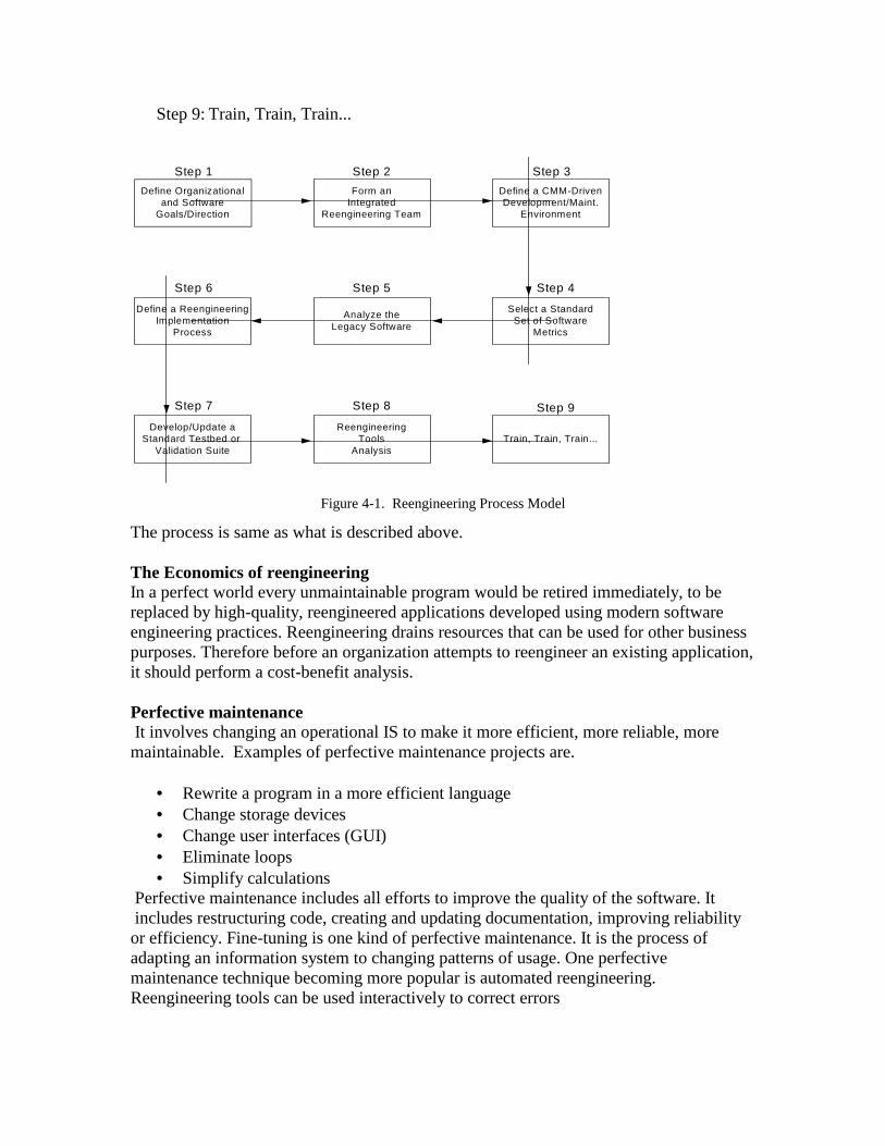
Step 9: Train, Train, Train...
Define Organizationaland Software
Goals/Direction
Form anIntegrated
Reengineering Team
Define a CMM-DrivenDevelopment/Maint.
Environment
Define a ReengineeringImplementation
Process
Analyze theLegacy Software
Select a StandardSet of Software
Metrics
Develop/Update aStandard Testbed or
Validation Suite
ReengineeringTools
AnalysisTrain, Train, Train...
Step 1 Step 2 Step 3
Step 6 Step 5 Step 4
Step 7 Step 8 Step 9
Figure 4-1. Reengineering Process Model
The process is same as what is described above. The Economics of reengineer ing In a perfect world every unmaintainable program would be retired immediately, to be replaced by high-quality, reengineered applications developed using modern software engineering practices. Reengineering drains resources that can be used for other business purposes. Therefore before an organization attempts to reengineer an existing application, it should perform a cost-benefit analysis. Perfective maintenance It involves changing an operational IS to make it more efficient, more reliable, more maintainable. Examples of perfective maintenance projects are.
• Rewrite a program in a more efficient language • Change storage devices • Change user interfaces (GUI) • Eliminate loops • Simplify calculations
Perfective maintenance includes all efforts to improve the quality of the software. It includes restructuring code, creating and updating documentation, improving reliability or efficiency. Fine-tuning is one kind of perfective maintenance. It is the process of adapting an information system to changing patterns of usage. One perfective maintenance technique becoming more popular is automated reengineering. Reengineering tools can be used interactively to correct errors

A reengineering tool is a CASE tool that analyzes a program and, with some human assistance and input, rewrites the program. An example where you can use a reengineering tool is to translate a program from one language to another or to translate from one database implementation to another. Perfective maintenance is a type of maintenance that includes reengineering, and is sometimes applied more broadly to include enhancement. Reengineer ing A type of maintenance performed to improve the design of some part of a software system, in general so that it has higher maintainability. In general, no new features are added for users. Reasons of having Reengineer ing
• New Interfaces (GUIs) • Object-Oriented Design/Code • Client Server Architecture • Preventive Maintenance
The growing problems of per fective maintenance due to which reengineer ing is used are Software maintainability is the modification of a software product after delivery to correct errors, improve performance (or other attributes), or adapt to new requirements.
� Software errors can be very expensive. In a recent study, the top 10 most expensive software errors were maintenance errors. In fact, the top 3 most expensive software errors involved a single line of source code and cost their respective organizations $1.6 billion, $900 million, and $245 million.
� perfective maintenance is very costly. A few statistics easily bears this out:
Maintenance costs (including personnel and hardware/software usage fees) run as high as 50-80% of the software life cycle resources or $30 billion a year in the United States alone. Approximately 50% of maintenance costs is spent on just understanding what the software does.
• The DoD spends approximately $24 billion on software each year. Maintenance accounts for about 70% of this budget. To cite one recent example, the software development costs for the F-16 jet fighter were $85 million. The projected software maintenance costs are $250 million
• It is estimated that it will cost $75 billion to fix the year 2000 problem in the USA alone.
� Maintenance personnel are getting scarce. According to USAF estimates,
25% of this country’s entire 18-to-25-year-old population will be required to maintain all our software systems by the year 2000 [Bush 88]. By the end of 1993, the DoD employed approximately 369,500 software personnel. By the year 2002, this force structure (and its budget) is to be reduced by 25% [Browning 93].

� Frequent failure rates � Complex design (e.g. unstructured code, tightly coupled to hardware or other
software, low cohesion, unknown development process, etc.) � Unpredictable “ ripple” effects � Unreliable or missing documentation � Obsolete hardware platforms � Loss of experienced maintenance programmers or original developers � Growing backlogs � Critical corporate knowledge is contained within the legacy software
Legacy software represents an enterprise model of the organization. If the software has been in use for a long time, and then it has most likely survived by providing a critical service. In fact, some software engineers believe that most organizations have already built the majority of their useful software systems. The original users and developers may no longer be available to explain all the reasons behind the creation of, and subsequent modifications to, the software.
� Reusable, reengineered software costs much less
Some examples where reengineer ing supports

1. Business Process Engineer ing
2. (Re) Engineer ing its business and its processes

3. Using Information Technology to suppor t Business Processes
Information Technology as a Business Process Enabler Automating: eliminate human labor Organizing: capture information for understanding Sequencing: alter process sequence, eliminate intermediates, and enable parallelism Tracking: monitor status and objects Analyzing: improve information analysis and decision-making Networking: connect processes across distances Integrating: coordinate between processes and tasks Intellectual: capture and distribute intellectual assets Software Reengineering Technique Overview

Question #4 What is the meaning of Mean Time to Repair (MTTR) for software? Answer #4 MTTR stands for Mean Time To Repair. MTTR is the most common measure of maintainability. It is the average time required to perform corrective maintenance on all of the removable items in a product or system. This kind of maintainability prediction analyzes how long repairs and maintenance tasks will take in the event of a system failure. Corrective maintenance being actions carried out to restore a defective item to a specified condition and tests, measurements, and adjustments made to remove or correct a fault. In other words MTTR is the average time to correct a failure and return the equipment to a condition where it can perform its intended function: the sum of all repair time incurred during a specified time period (including equipment test time), divided by the number of failures during that period. MTTR= Total repair time / # of failures MTTR also factors in to other reliability and maintainability predictions and analyses. MTTR can be used in a reliability prediction in order to calculate the availability of a product or system. Availability is the probability that an item is in an operable state at any time, and is based on a combination of MTBF and MTTR. TO decrease MTTR means to increase customer satisfaction. Repair Turn Around If you repair your products on your repair department, you have a better understanding of the repair turn around on time base. It is very important to optimize customer satisfaction

Frequent failure par ts and products To increase product reliability, you should find out frequent failure parts so that you can replace it with different component. Also, this data can inform you adequate spare parts stock at your service site in somewhere else in the world. Thus, the total elapsed time (clock hours) for corrective maintenance divided by the total number of corrective maintenance actions during a given period of time. MTTR may be calculated by the following formula:
( )i
N
i
ii
N
i
TFE
ETTFEMTTR
0
0)()(
=
=×
=
Where: i = On equipment corrective maintenance actions iTF = Task frequency of " i " on equipment maintenance action
iET = Mean elapsed time of the " i " on equipment corrective
maintenance action
N = Total number of on equipment corrective maintenance actions charged against the LCN/ALC item under analysis
MTTR is documented as both technical and operational characteristics. Technical parameters reflect the technical reliability that the system/ equipment must demonstrate. In determining these parameter values, all failures and resultant actions to restore the item (e.g., a broken tail light is a technical, but not operational characteristic). Operational parameters reflect operational reliability and maintainability characteristics that the system must demonstrate. Only operational mission failures and the resultant tasks are included (e.g., engine failure will result in mission abort which is both an operational and technical failure).
REQUIRED MEAN TIME TO REPAIR is an MTTR representing the supportability requirement/specification MTTR. Thus MTTR is the average time that a device will take to recover from a non-terminal failure. Examples of such devices range from self-resetting fuses (where the MTTR would be very short, probably seconds), up to whole system, which might have to be replaced. The MTTR would usually be part of a maintenance contract, where the user would pay more for a system whose MTTR was 24 hours, than for one of, say, 7 days. This means

the supplier is guaranteeing to have the system up and running again within 24 hours (or 7 days) of being notified of the failure. Some devices have a MTTR of zero, which means that they have redundant components, which can take over, the instant the primary one fails.� Elements of MTTR: The MTTR prediction of a system begins at the replaceable unit level(RUL) where a defective unit is removed and replaced in order to restore the system to its original condition. Then the system MTTR predictions are accomplished by integrating the MTTR’s of maintainable units. The following defines the elements used in the MTTR prediction of a system:
• Fault isolation: Time associated with those tasks required to isolate the fault to the item.
• Disassembly: Time associated with gaining access to the replaceable item or items identified during the fault correction method.
• Interchange: Time associated with the removal and replacement of a faulty replaceable item or suspected faculty item.
• Reassembly: Time associated with closing up the equipment after interchange is performed.
• Alignment: Time associated with aligning the system or replaceable item after a fault has been corrected.
• Checkout: Time associated with the verification that a fault has been corrected and the system is operational.
• Constant failure rates: The rate of failures that result from strictly random or chance causes. This type of failure occurs predominantly in the useful life period of a unit.
• K factor: For on-orbit tasks, a conversion factor may be applied to convert elemental task times performed in 1-g environment to micro-gravity environment.
Mean Time to repair predictions In general, the MTTR of a system is an estimated average elapsed time required to perform corrective maintenance, which consists of fault isolation and correction. For analysis purposes, fault correction is divided into disassembly, interchange, reassembly, alignment and checkout tasks. The repair time of a maintainable unit generally consists of both a large number of relatively short-time repair periods and a small number of long-time repair periods. The former would correspond to the more usual case where the failed unit is replaced by a spare at the operational site on detection of a failure. The longtime downtimes would occur when diagnosis is difficult or removing a defective part is complicated due to, for instance, rusted/stripped mounted nuts. Having a collection of such field data provides the design engineer an opportunity to assess the MTTR of the current system as it matures, or to predict the MTTR of a new system according to its featured with the current system.

MTTR is a useful parameter that should be used early in the planning and designing stages of a system. The parameter is used in assessing the accessibility/ locations of the system components; for example, a component that often fails should be located where it can easily be removed and replaced. The estimated MTTR may also dictate changes in system designs in order to meet the turn-around time criteria for critical systems. In addition, the parameter helps in calculating the life cycle cost of a system, which includes cost of the average time technicians spend on a repair task. MTTR is defined as the average time necessary to troubleshoot, remove, repair, and replace a failed system component. An interval estimator for MTTR can be developed from the mean of the sample data, within a lower and an upper limit with a confidence bound. For example, from the sample data set, one can find with 90% confidence that the ranges 3.2 to 4.2 will contain the population mean. Unfortunately, the exact MTTR of a system can never be found due to data uncertainties. Some ground rules and assumptions that apply:
• MTTR does not include the maintenance overhead, which is generally non-related task time such as time to fill out a requisition, time to go to get tools, break-time, time waiting for parts, etc.
• Worksite time is only variable considered. • All equipment experiences a constant failure rate. • All tasks are performed sequentially by one member. • Maintenance is performed in accordance with established maintenance procedures
and trained personnel. • The prediction depends on the use of recorded reliability and maintainability data
and experience that have been obtained from comparable systems and components under similar conditions of use and operation.
MTTR Maintainability Analysis: Like MTBF, which is the average time the equipment performed its intended function between failures; productive time divided by the number of failures during that time, is to failure rate in reliability, MTTR is the reciprocal mathematical function of the repair rate. The task-time analysis will provide the analyst with repair times. Each LRU (Least replaceable/repairable unit must be examined, decomposed to its lowest entity without jeopardizing the unit integrity, and analyzed for corrective maintenance. These LRUs correspond to the reliability analysis systems breakdown. The corrective maintenance cycle consists of the following activities:
• Failure Detection Time: A failure must have occurred in order to initiate a corrective action. Analyst use their judgment gained from experience.
• Localization and isolation time: The fault/failure detected is isolated through diagnostic testing and the probable source of the problem is isolated.
• Disassembly time: The faulty item is disassembled to repair the failed part. • Reassembly time: The unit is assembled upon completion of the repair.
• Alignment and Adjustment Time: The repaired unit is aligned or adjusted according to product specifications.
• Verification Time: A functional test(s) is performed to determine product suitability for return to service.
These repair times are summed linearly to determine the repair rate for that item line entry. The analysis worksheet is laid out like a spreadsheet. The leftmost column lists each element to be analyzed. The header lists each repair activity outlined above, and the rightmost column holds the totals for corrective maintenance times. The analyst then tallies the total repair times at the bottom of the page for that LRU. The reciprocal MTTR is then calculated:
MTTR = 1 / repair rate Each LRU has an MTTR, and as with reliability’s MTBF and failure rates, the analyst sums the repair rates for the system LRUs before calculating the MTTR. A system availability calculation requires a specific relationship between reliability and maintainability factors. The most important relationship is:
A = MTBF / (MTBF + MTTR) Implement the MTTR Process: Accurately estimating the MTTR of a new system is more than applying the derived formulas. The designer must know the overall maintenance concept and operating conditions of the new system; for example, how and where the system is going to be operated and how its failed units will be swapped out. With this background, the designer can proceed to approximate the maintenance procedure of the new system, then select an existing system that has been exposed to similar operating conditions and that has a mature set of operating data. After the similarity between two systems is assessed, the designer then can determine certain conversion factors needed to make the existing system data more applicable to the new system. The predictions for the new system are more meaningful and accurate.