kathrin d or er ian brooks jonas buchli mobile robotic ... · an industrial robot arm for the rst...
TRANSCRIPT
Markus Giftthaler · Timothy Sandy · Kathrin Dorfler · Ian Brooks ·Mark Buckingham · Gonzalo Rey · Matthias Kohler · Fabio Gramazio ·Jonas Buchli
Mobile Robotic Fabrication at 1:1 scale:the In situ FabricatorSystem, Experiences and Current Developments
Abstract This paper presents the concept of an In situFabricator, a mobile robot intended for on-site manu-facturing, assembly and digital fabrication. We presentan overview of a prototype system, its capabilities, andhighlight the importance of high-performance control,estimation and planning algorithms for achieving desiredconstruction goals. Next, we detail on two architecturalapplication scenarios: first, building a full-size undulat-ing brick wall, which required a number of repositioningand autonomous localisation manoeuvres. Second, theMesh Mould concrete process, which shows that an Insitu Fabricator in combination with an innovative digitalfabrication tool can be used to enable completely novelbuilding technologies. Subsequently, important limita-tions and disadvantages of our approach are discussed.Based on that, we identify the need for a new type ofrobotic actuator, which facilitates the design of novelfull-scale construction robots. We provide brief insightinto the development of this actuator and conclude thepaper with an outlook on the next-generation In situFabricator, which is currently under development.
This research was supported by the Swiss National Sci-ence Foundation through the National Centre of Compet-ence in Research (NCCR) Digital Fabrication (Agreement#51NF40 141853) and a Professorship Award to JonasBuchli (Agreement #PP00P2 138920).The authors would like to thank Norman Hack, Nitish Kumarand Alexander N. Walzer for providing details on the MeshMould process. Special thanks also go to the NCCR techni-cians Michael Lyrenmann and Philippe Fleischmann for theirtechnical support on IF1.
Markus Giftthaler, Timothy Sandy, Jonas BuchliETH Zurich, Institute for Robotics and Intelligent SystemsE-mail: {mgiftthaler, tsandy, buchlij}@ethz.ch
Kathrin Dorfler, Matthias Kohler, Fabio GramazioETH Zurich, Chair of Architecture and Digital FabricationE-mail: {doerfler, kohler, gramazio}@arch.ethz.ch
Ian Brooks, Gonzalo ReyMoog Inc. E-mail: {grey, ibrooks}@moog.com
Mark BuckinghamRenishaw PLC. E-mail: [email protected]
Keywords Construction Robotics · Digital Fabrication ·Mobile Manipulation · In situ Fabrication
1 Introduction
1.1 Motivation
In the past decades, there has been significant effort toraise the degree of automation in building constructionand architecture. Digital fabrication promises a revolu-tion in the construction industry and exhibits a greatpotential for novel architectural approaches and alternat-ive tectonics.
The tight integration of planning and constructionallows the architect to optimise processes on multiplelevels. During planning, shapes can be optimised in orderto create highly differentiated forms which minimise theusage of material. For construction, novel processes areenabled which minimise material waste, increase efficiencyand improve working conditions. To handle the high levelof geometric- and fabrication-informed complexity in anefficient manner, using digitally controlled machinery forthe construction of computer-generated forms is essential.Furthermore, by tightly integrating digital design andfabrication, the performance and aesthetics of the struc-tures being built can be improved through continuousadaptation of the design and process in real time.
To date, digital fabrication has had the most impactin the area of off-site prefabrication in which smaller com-ponents of a building are made in a dedicated factory andthen transported to the building site for final assembly(an example is the roof presented in [26]). Directly onbuilding sites, however, the level of automation is stillcomparably low. The final assembly of building compon-ents is heavily dominated by manual labour, which breaksthe digital process chain between design and making.
Motivated by this insight, recent research goes in thedirection of on-site digital fabrication, the autonomousfabrication of buildings (or building components) on thespot, generally referred to as In situ Fabrication. Within
arX
iv:1
701.
0357
3v1
[cs
.RO
] 1
3 Ja
n 20
17
2
this field, one approach addresses on-site additive manu-facturing with large scale gantry systems [15, 4]. However,the most striking disadvantage of this approach is thefact that the size of the employed machine constrains thesize of the object being built. Therefore, using mobile,autonomous robots can be considered a more versatileoption as it allows for the fabrication of structures signi-ficantly larger than the tool employed.
A number of attempts have already been made todevelop mobile robots for on-site robotic construction.Early exploratory setups deserving explicit mentioningwere the robots “Rocco” [1] and “Bronco” [19]. However,these systems were designed for relatively standardisedand strictly organised production processes. “Dimrob”was presented in [10], but several factors restricted theplatform’s usefulness for a wide range of building scen-arios. It could only be repositioned manually and didnot make use of advanced sensing and control concepts,therefore requiring the use of static support legs andeffectively rendering it as a movable fixed-base robot.In [14], a full-scale mobile system was shown to be cap-able of printing a large-scale foam structure, however alsousing a quasi fixed-base setup and without strict accuracyrequirements. In [12], a self-supporting 3d printing systemwhich can move on the printed structure was presented.For a recent, more complete survey of mobile robots inconstruction, we refer the reader to [2].
To the best of our knowledge, to date, there is norobotic platform which fully satisfies the requirementsfor autonomous, mobile robotic construction at 1:1 scale.While there has been a number of research projects aimingat enabling mobile robots for on-site robotic construction,we believe that the key challenge which has preventedsignificant breakthroughs so far is that such machinesmust be able to robustly handle the unstructured natureof the building construction site. Because constructionsites are constantly changing and relatively dirty andcluttered environments, it is not possibly to apply clas-sical industrial automation approaches in controlling suchsystems.
This challenge poses design, engineering and researchquestions at many different levels. While environmentaland hardware requirements (e.g. payload requirements)determine the design, shape and physical realisation ofthe mobile robot itself, the role of state estimation, con-trol and planning algorithms, as well as their properimplementations, should be considered in the design ofthe overall system such that it can be effectively oper-ated by a non-expert user. Finally, the system needs tobe integrated into layouting systems and architecturaldesign software in such a way that there can be a seamlessinteraction between design and construction.
1.2 Contributions and Structure of this Paper
In this paper, we present the ‘In situ Fabricator’ con-cept: a class of mobile robot specially designed for on-site
digital fabrication. First, we propose a list of basic re-quirements for an In situ Fabricator in Section 2. Second,we present a systematic overview of the IF1, a first pro-totype built from off-the-shelf components, in Section 3.Next, we introduce the fully-integrated digital tool-chaindeveloped for the system, spanning from digital design tothe planning and control for the mobile system. In Sec-tion 4, we present the planning, state estimation and con-trol algorithms methods used for achieving the requiredcapabilities for digital fabrication on IF1. In Section 5,we explain the IF1’s integration into architectural designand planning Software. We highlight the capabilities ofthis fully-integrated system through two architecturaldemonstrators, in Section 6. First a dry brick wall, whichdemonstrates the IF1’s ability to build geometrically com-plex shaped structures at full scale. Second, we showcasethe Mesh Mould project, which shows the IF1’s potentialto enable completely new building processes.
Reliable, dedicated hardware plays an important rolein the construction sector. The characteristics of tasksappearing in building construction differ significantlyfrom the task spectrum that classical industrial roboticscan cover today. Therefore, in Section 7 we outline theinherent limitations of IF1 and related concepts basedon commercially available industrial robotics. We listimportant conclusions drawn from those limitations, andhighlight the development of a novel type of actuationdesigned specifically for the needs of full-scale roboticconstruction, in Section 8. Based on that, we introducethe concept of the future In situ Fabricator (IF2), whichis currently under development.
2 Requirements and Definition of an In situFabricator
Looking at a typical construction site today, one willoften find a variety of machines of different sizes andwith different specialised purposes. It is likely that wewill see a similarly broad spectrum of different robotsfor specialised tasks in building construction in the fu-ture. In our research we have decided to first consider anintermediately-sized class of mobile robots dedicated toa broad variety of fabrication tasks, referred to as In situFabricators. We believe that such a machine could havea significant impact on building construction in the nearfuture and would effectively demonstrate the capabilitiesof on-site robotic digital fabrication. In situ Fabricatorsare defined through the following set of requirements:
Control and state estimation:
– provide 1 to 5 millimetre positioning accuracy at theend effector.
– can operate within a local portion of the constructionsite. Moving obstacles, humans, and changing scenesoutside of this area should not impact performance.
3
– is mobile in non-flat terrain with obstacles and chal-lenges as found on a typical construction site.
– can operate with limited human intervention. Themachine alone should offer the modality for achievingthe overall accuracy of the building task.
Size and workspace constraints:– can reach the height of a standard wall.– can fit through a standard door (in our case defined
as a 80 cm wide Swiss standard door).– can be loaded on a pallet/van.Versatility and customisation:– can be equipped with different tools or end effectors
to perform a wide range of building tasks.– have sufficient payload to handle heavy and highly
customised digital fabrication end effectors.– can work in confined non-ventilated spaces.– are protected against dust and water ingress.Power supply:– can be plugged into standard mains power.– has sufficient on board power for phases of construc-
tion where no external power supply is available (e.g.during transportation to and from the constructionsite)
Usability and integration:– can provide required information to the architectural
planning and control environments, e.g. current robotlocation, building state, etc.
– provides interfaces for interaction with an operatorwho is not a robotics expert.
Note that we are not addressing the whole buildingproduction process chain, which would also include lo-gistics and supply management. While this domain offersgreat opportunities for automation and optimisation, ourwork focuses on a machine intended solely or the produc-tion of the desired structure. As such, special attention isput on creating the possibility to close the feedback loopbetween design and the building process through in-theloop sensing and control.
3 In situ Fabricator 1
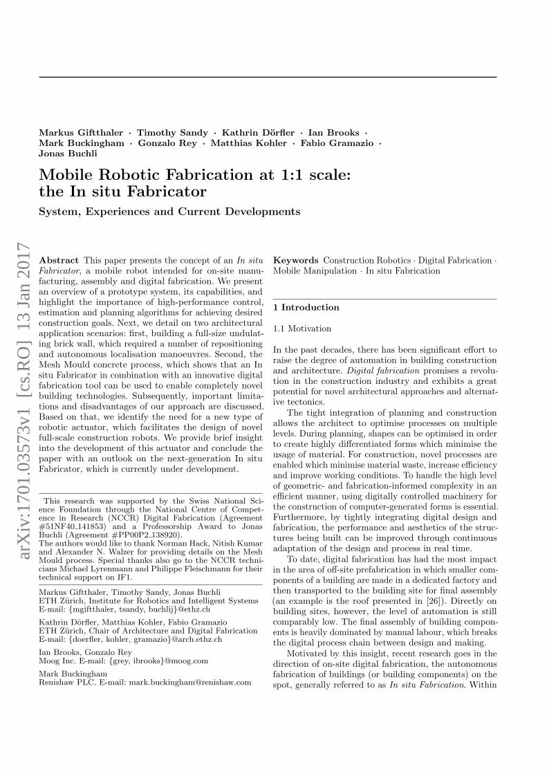
In 2014, the first prototype machine was realised, the IF1,which is shown in Figure 1. It is partially based on existingparts from the Dimrob project [10] and mostly consists ofcommercially available off-the-shelf components. A briefoverview of the robot hardware is given in the followingsection.
IF1 is equipped with an ABB IRB 4600 robot armwith 2.55 m reach and 40 kg payload. The decision to usean industrial robot arm for the first prototype allowedfor quick progress in providing a fully-sized mobile robotfor initial research, although its limitations were alreadyknown at this point. All required industrial robot control-ler electronics from an ABB IRC5 controller unit werefitted to the robot base in a custom, more compact, form.
Figure 1: The In situ Fabricator 1 (without end effector).
The arm is position-controlled, and a commercial controlinterface provided by the manufacturer allows to sendreference position and velocity commands at 250 Hz rate.
IF1 is electrically powered. It carries four packs ofLi-Ion batteries with capacity for 3-4 hours of autonom-ous operation at average machine load without beingplugged into mains power. The robot features an on-board charging system and a power conversion systemoffering currents between 5-48 V DC and 230-400 V ACat 50 Hz.
The robot also carries a custom on-board hydraulicsystem, which is used to power its tracks through hy-draulic motors, but can also provide hydraulic power tothe tool mounted at the end effector. Its core compon-ents are a compact AGNI DC electric motor attachedto a pump delivering hydraulic pressure at 150 bar. Thehydraulic system is designed such that the tracks canbe driven both with manual levers or through automaticoperation, in which case the flow to the tracks’ hydraulicmotors is controlled by proportional valves. The IF1 canachieve a maximum driving speed of 5 km/h at a totalweight of 1.4 tons.
Depending on the desired task, IF1 can be equippedwith additional exteroceptive sensors. All sensors andactuators are driven by an on-board computer systemwhich runs a hard-real-time enabled version of Linuxwith the Xenomai kernel-patch [27]. The main on-boardcomputer unit features an Intel i3-3220T processor with2.8 GHz and 4 GB RAM, which is sufficient to run basicstate estimation, planning and control algorithms. Com-putationally more intensive tasks are run externally, withwireless communication provided through ROS [20] or acustom real-time enabled TCP/IP implementation.
The standard mounting flange of the industrial armand a general set of power and data connections areprovided at the end-effector to allow for the attachment ofa wide range of tools. IF1 also provides various mountingpoints for temporary (complementary) equipment suchas vacuum pumps or welding equipment.

4
4 State Estimation, Planning and Control
For enabling autonomous localisation, driving and build-ing, we have implemented a mix of well-established aswell as novel algorithms for state-estimation, planningand control. The methods described in the following sec-tions have proven to reach high positioning accuraciesover the course of long building processes and many robotrepositioning manoeuvres without reliance on externalreference systems.
4.1 Sensing and State Estimation
In order for a robot to build structures on the constructionsite with high accuracy, it needs to be able to track theposition of the tool it is using with respect to some fixedreference frame. This section describes the sensing systemdeveloped for IF1. These developments are broken up intothree main functional parts: robot localisation within theconstruction site, alignment between the sensing referenceframe and the CAD model, and feedback of the buildingaccuracy during construction.
While there is an extensive body of research fromthe robotics community in localisation [3], motion track-ing [23], and mapping [25] for mobile robots, these systemsdo not directly translate to the construction site. Onemain reason for this is that most robotics applicationsdo not consider the millimetre-scale relative positioningaccuracy required for building tasks. Another reason isthat most applications do not consider any prior informa-tion about the environment in the sensing system, whilethere is an abundance of prior information for buildingconstruction, in the form of the CAD model or otherplan data. Our work in sensing for IF has therefore fo-cused on tailoring existing sensing solutions from therobotics community to the application of on-site buildingconstruction.
4.1.1 Localisation
The most basic function of an In situ Fabricator’s sensingsystem is to localise the end-effector of the robot with re-spect to a fixed reference frame. In conventional industrialrobots, this is easily achieved using the rotary encodersin the robot’s joints since the robot is sufficiently stiff andrigidly attached to the ground. For a mobile robot, how-ever, exteroceptive sensing is required to ensure zero-driftpose estimates. A strategy typically used for such a sys-tem is to track a known point on the robot with respectto a static sensor system (e.g. a Vicon motion trackingsystem or a Hilti Total Station). While these systemscan provide high-accuracy positioning data with minimalintegration effort, they can be prohibitively expensive andtake considerable initial setup time and effort. Further-more, the measurement frequency and delay is often notoptimized for mobile applications. Alternatively, sensors
Figure 2: Point cloud of our lab captured by IF1.
can be mounted directly on the robot and used to locatevisual references in the robot’s workspace. While thesesolutions are much lower cost, they typically require signi-ficantly more integration effort, as the sensor informationmust be heavily processed to extract the informationrequired for localisation (e.g. image processing to extractthe local visual features). This strategy is pursued forIF as to avoid the presence of visibility constraints froman external measurement system and because we believethis sensing modality can be more easily expanded tofeed back additional pieces of information to inform theremainder of the building process (as in Section 4.1.3).
We have developed two separate sensing systems foruse on IF1, each supporting one of the application ex-amples presented in Section 6. For the brick-laying ex-periments, we mounted an off-the-shelf laser-range-finder(LRF) on the end-effector of IF1. By executing sweep-ing motions with the wrist of the arm, we could build3D point clouds of the robot’s surroundings (Figure 2).These point clouds were then registered versus an initialpoint cloud to infer the robot’s relative motion (see [5]for implementation details). The main shortcoming ofthis method is that it assumes that the majority of therobot’s environment remains unchanged during construc-tion, which is a bad assumption since construction sitesare constantly changing environments. Subsequent effortstherefore focused on sensing modalities which allow therobot to localise using only features located directly inthe vicinity of its workpiece, see [22].
For later experiments, we switched to camera-basedsensing solutions. We find that the main advantage ofusing cameras over LRFs is their adaptability to theapplication. While the absolute accuracy of LRF meas-urements is determined by the sensor’s internal hardware,camera setups give the user the flexibility to ‘tune’ thesystem’s accuracy to the application by changing theresolution, lens, or position of the cameras. For the MeshMould project presented in Section 6.2, we use the samemodel of camera to perform two very different sensingtasks by simply configuring and positioning the cameras
5
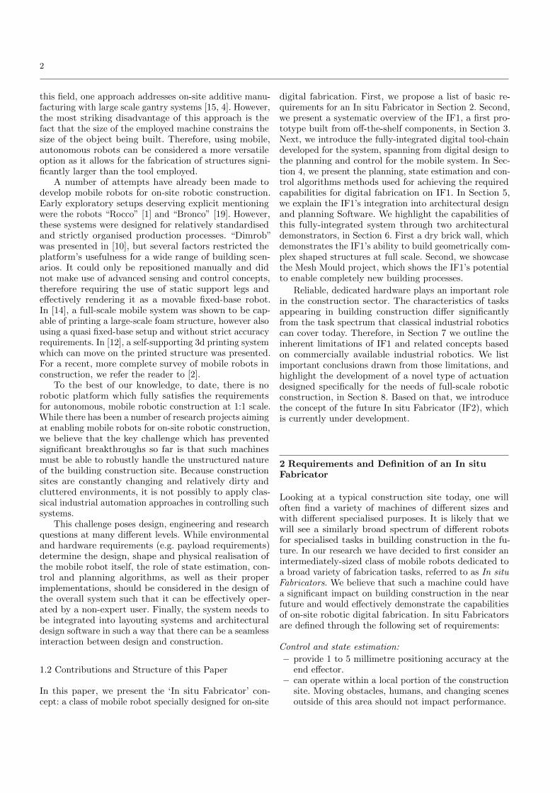
Figure 3: Stereo image pair taken with the cameras onthe Mesh Mould toolhead during fabrication. The twodetected wire segments are highlighted in blue and redin each image. The next segment of the mesh was weldedto these segments.
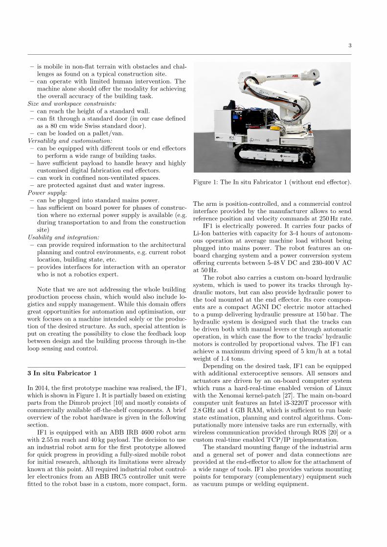
Figure 4: Point cloud of the building site, showing the re-gistered positions of geometric models of the attachmentspillars (red) and floor (blue) of the CAD model.
differently. For localisation, any number of cameras fixedto the base of the robot observe AprilTag [18] fiducialmarkers to localise relative to a calibrated map of the tagpositions in the workspace. For localisation of the wiremesh and collision avoidance of the tool with the mesh, astereo pair of cameras use line detection and matching tolocate the next wire to be processed during mesh buildup.Figure 3 shows a stereo image pair from this system withthe detected wires highlighted. With this sensing system,it is easy to see how the same cameras can be tailoredto very different sensing tasks simply by modifying theirconfiguration and the subsequent image processing. Forthis reason, we feel that cameras are the sensing modalitywith the highest potential for on-site robotic buildingconstruction.
4.1.2 Alignment with the CAD Model
In most architectural applications, localising the tool withrespect to some general fixed global reference frame is notenough. Any structure built needs to be attached to anexisting element of the construction site and must be belocated with sufficient precision that the overall accuracyof the construction is ensured. For in situ fabrication,this can be achieved by aligning the sensing referenceframe with the reference frame of the CAD model ofthe structure being built. This requires determining theposition of either the external sensing system or the visual
features used for localisation in the CAD model. Thisalignment step can typically be done just once beforebuilding. During this alignment step, key interfaces onthe construction site, to which the structure being buildmust attach, can be identified and their positions fed backto update the design of the structure to accommodateany inaccuracies which may be present.
In the IF1 brick laying work (Section 6.1), localisationis performed relative to a reference scan of the construc-tion site taken before starting to build. The referencescan is aligned with the CAD model of the structure byregistering features of the constructions site to which thewall was anchored (Figure 4). In this way, the robot isnot only able to localise relative to the CAD model, butwe are able to adjust the parametric design of the wallto match the true positions of the pillars within the con-struction site. For the Mesh Mould project (Section 6.2)we need to align our map of the visual fiducial poses tothe CAD model of the wall. This is done simply by usingthe mesh detection cameras to locate the first layer ofthe mesh, which is built by hand and attached to thesupporting wall before building. Once this layer is located,the tags seen from that robot position can be used toalign the tag map with the first layer of the mesh in theCAD model.
4.1.3 Feedback of Building Accuracy
We believe that, in order to realise the full potential ofrobotic on-site construction technology, the robot usedshould be able to feed back data about the progress of thebuilding project during construction. In this way, buildinginaccuracies and changing conditions in the constructionsite can be compensated for during construction. Thisis especially crucial in building processes where materialdoes not behave predictably after processing. This is thecase in the Mesh Mould project. As the wire mesh isconstructed, internal tension between the wires tends topull the mesh away from the position in which it waswelded. The direction and amount of deflection is difficultto model, therefore real-time feedback of the materialbehaviour is required to ensure accurate construction. Byusing the two coupled measurement systems described,however, IF can determine the shape of the last wirewelded to the mesh in the global reference frame, there-fore observing how well it matches the initial design. Inthe presence of significant errors in the wire contour, thebuilding plan for the next layers of the mesh can be ad-justed to compensate for the error and effectively pull themesh back into alignment with the CAD model. It shouldbe noted that this functionality is a natural extension ofthe camera sensing system since various custom featurescan be extracted from images relatively easily. It wouldbe very difficult, however, to do this compensation if acommercial off-board sensing systems was used, since itwould not be capable of detecting the contour of the wiremesh.

6
Figure 5: Snapshots from a motion sequence with an end effector position constraint executed on IF1 usingConstrained Sequential Linear Quadratic Optimal Control in a Model Predictive Control fashion. The task is toreposition and reorient the base while keeping the end effector at a constant position.
4.2 Planning and Control
Generally speaking, we approach the planning and controlproblem for In situ Fabricators through Optimal Control.Optimal Control solves the problem of finding a con-trol policy for a dynamic system such that a predefinedcriterion of optimality is achieved. It can be used to com-pute either open-loop trajectories, which is the domain oftrajectory optimisation, to compute feedback laws whichstabilise given trajectories, which is pure feedback control,or both at the same time. By solving a correspondingmathematical optimisation problem, we find optimal tra-jectories and/or control laws that steer the system to adesired pose while minimising some cost function and re-specting constraints at the same time. Difficulties arisingin planning and control for mobile construction robotsare obstacles, inherent motion constraints (for examplenon-holonomic constraints due to wheels or tracks), mo-tion with contact and interaction forces and accumulatedmodel uncertainties. The latter is an important issue forIF1, as tracked locomotion on imperfect ground can notbe modelled with high accuracy. In contrast to classical,sampling based planning algorithms like Rapidly Explor-ing Random Trees and Probabilistic Roadmap methods(see [17] for an overview), or the integrated kinematicplanners typically supplied with industrial robots, manyOptimal Control algorithms can handle some of thesedifficulties with reasonable complexity.
For IF1, we have integrated different control and plan-ning approaches, which allow us to consider base- andarm motion either separately or jointly as a whole-bodyproblem. Coordinated whole-body motions with non-holo-nomic base constraints and holonomic operational-spaceconstraints (e.g. tool position constraints) are generatedusing Constrained Sequential Linear Quadratic (SLQ)Optimal Control. Although being an iterative OptimalControl algorithm, it is computationally highly efficient,as it features linear time complexity O(n). Feedforwardtrajectories and feedback are optimised simultaneously,which generalises the control policy in the vicinity ofthe nominal, optimal trajectory. The resulting feedbackgains are compliant with non-holonomic constraints. OnIF1, we run this algorithm in a Model Predictive Con-trol (MPC) fashion at up to 100 Hz update rate, wherethe feedback loop is closed through an on-board visual-inertial state estimator. This allows us to achieve robust
positioning despite the presence of model uncertaintiesand external perturbations. Figure 5 shows snapshotsfrom a motion sequence with an end effector positionconstraint executed on IF1 using Constrained SLQ in anMPC fashion. More details about SLQ MPC on IF1 areprovided in [8].
When performing sequential building tasks, as forexample demonstrated in [22], or when more obstacles arepresent, we separate the base- and arm control problemand move base and arm sequentially. In this case, we use aconstrained version of the stochastic planner STOMP [13]for trajectory optimisation. For trajectory following, onecan still apply the constrained feedback gains obtainedfrom SLQ.
For manipulation, we combine individually plannedsequences of arm/base motion with a library of task-specific, pre-programmed manipulation-primitives (e.g.picking up a brick from the brick feeder or moving a jointat constant velocity). This combination has has provensufficient for a number of building tasks.
Note that our approach can typically handle a mod-erate number of obstacles easily and reliably. However,at the current stage, we cannot handle heavily clutteredenvironments with a large number of possibly intersectingor dynamically changing obstacles. This would lead tostrongly non-convex and ill-posed optimisation problemswhich cannot be treated in a classical Optimal Controlsetting. The combination of our Optimal Control frame-work with higher-level planners which are able to negoti-ate heavily cluttered environments is part of our futureresearch.
5 Integration into Architectural Design andPlanning Software
A major interest in the development of the In situ Fabric-ator is to tightly integrate its functions and capabilitiesinto an architectural planning framework, in order tomake its features directly available for architects anddesigners. Eventually we are aiming to see the generationand rationalisation of shapes to be directly influencedby the specific logic of making – in this case, next tothe choice of a material and assembly system, this is thefeature of mobility and the extended workspace of themobile robot.
7
To fully exploit the design-related potentials of usingsuch a robot for fabrication, it is essential to make use notonly of the manipulation skills of this robot, but to alsouse the possibility to feed back its sensing data into thedesign environment. This allows the system to guide andinform a running fabrication process such as to be able todetect and react upon unforeseen assembly tolerances andprocess-related uncertainties. Furthermore, the systemcan base immediate design decisions on the informationextracted from sensors, allowing a high level of flexibility,autonomy and control in fabricating an architecturalartifact.
Motivated by this, the high level planning of fabrica-tion tasks, such as the sequencing of the mobile robot’spositions and fabrication procedures and computing thearm, base and end effector positioning commands, isimplemented within an architectural planning tool, inour case Grasshopper Rhinoceros [21]. A TCP/IP pluginallows for the online control the robot’s arm and base,and gives access to the robot’s state estimator, planningroutines and movement primitives. This approach is alsodetailed in [5, 16]. Generally speaking, the robot’s setupis designed to allow for feedback loops at multiple levelsof the system: All time-sensitive tasks are executed bycontrol loops running on the robot’s low-level computerwhile the control loop over the overall building process isclosed via the architectural planning tool.
6 Architectural Demonstrators and Examples
The main drivers for the development of the IF1’s func-tionality and software framework were the architecturaldemonstrators shown in this section. The challenge offabricating multiple architectural prototypes with an in-creasing level of complexity was specifically chosen togradually advance the generic features of the robot. Therealisation of these demonstrators was significant for eval-uating chosen methods and to learn what is necessary –from both the robotics and the architecture point of view– to enable automated material deposition and assemblyprocesses in an unstructured, cluttered, and ever chan-ging environment such as a construction site. To date,this enables us to build customised, geometrically com-plex structures accurately over the course of the entirebuilding space.
6.1 Undulating Brick Wall
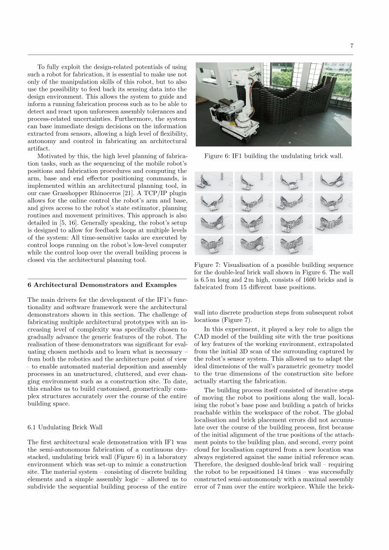
The first architectural scale demonstration with IF1 wasthe semi-autonomous fabrication of a continuous dry-stacked, undulating brick wall (Figure 6) in a laboratoryenvironment which was set-up to mimic a constructionsite. The material system – consisting of discrete buildingelements and a simple assembly logic – allowed us tosubdivide the sequential building process of the entire
Figure 6: IF1 building the undulating brick wall.
Figure 7: Visualisation of a possible building sequencefor the double-leaf brick wall shown in Figure 6. The wallis 6.5 m long and 2 m high, consists of 1600 bricks and isfabricated from 15 different base positions.
wall into discrete production steps from subsequent robotlocations (Figure 7).
In this experiment, it played a key role to align theCAD model of the building site with the true positionsof key features of the working environment, extrapolatedfrom the initial 3D scan of the surrounding captured bythe robot’s sensor system. This allowed us to adapt theideal dimensions of the wall’s parametric geometry modelto the true dimensions of the construction site beforeactually starting the fabrication.
The building process itself consisted of iterative stepsof moving the robot to positions along the wall, local-ising the robot’s base pose and building a patch of bricksreachable within the workspace of the robot. The globallocalisation and brick placement errors did not accumu-late over the course of the building process, first becauseof the initial alignment of the true positions of the attach-ment points to the building plan, and second, every pointcloud for localisation captured from a new location wasalways registered against the same initial reference scan.Therefore, the designed double-leaf brick wall – requiringthe robot to be repositioned 14 times – was successfullyconstructed semi-autonomously with a maximal assemblyerror of 7 mm over the entire workpiece. While the brick-
8
(a) Empty mesh. (b) Filled mesh.
Figure 8: Mesh Mould demonstrators built by IF1.
laying was done autonomously, feeding the robot withbricks was accomplished manually.
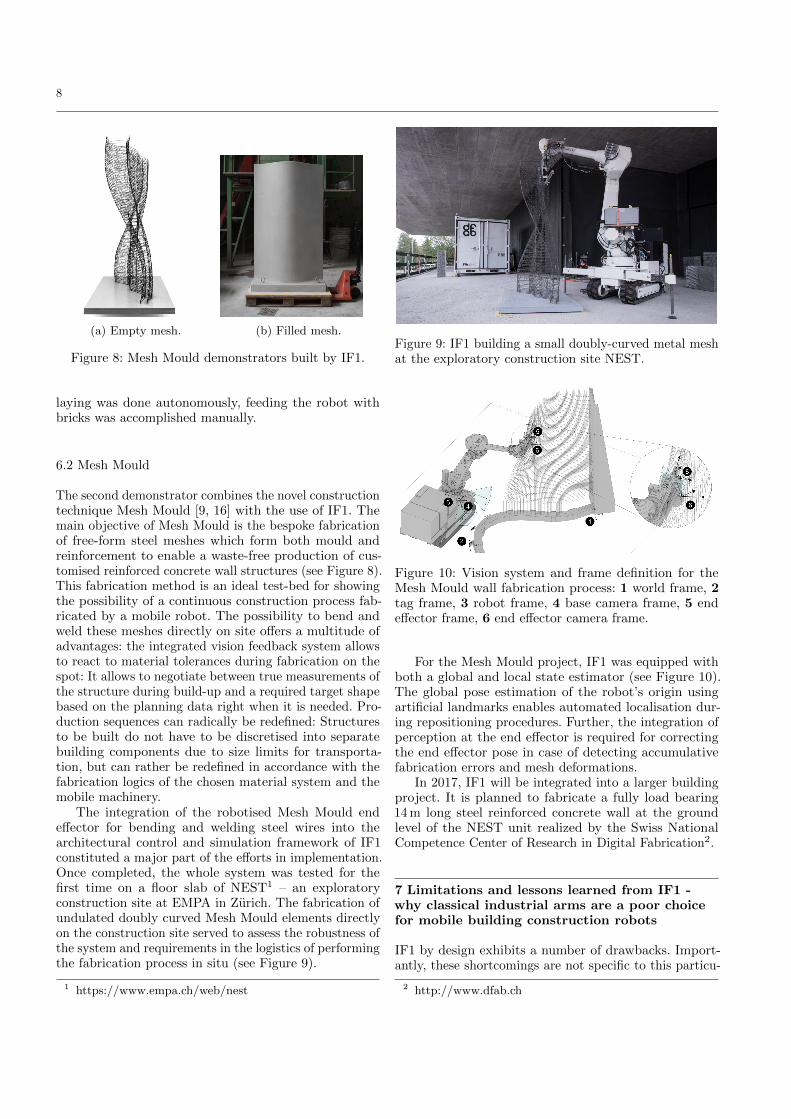
6.2 Mesh Mould
The second demonstrator combines the novel constructiontechnique Mesh Mould [9, 16] with the use of IF1. Themain objective of Mesh Mould is the bespoke fabricationof free-form steel meshes which form both mould andreinforcement to enable a waste-free production of cus-tomised reinforced concrete wall structures (see Figure 8).This fabrication method is an ideal test-bed for showingthe possibility of a continuous construction process fab-ricated by a mobile robot. The possibility to bend andweld these meshes directly on site offers a multitude ofadvantages: the integrated vision feedback system allowsto react to material tolerances during fabrication on thespot: It allows to negotiate between true measurements ofthe structure during build-up and a required target shapebased on the planning data right when it is needed. Pro-duction sequences can radically be redefined: Structuresto be built do not have to be discretised into separatebuilding components due to size limits for transporta-tion, but can rather be redefined in accordance with thefabrication logics of the chosen material system and themobile machinery.
The integration of the robotised Mesh Mould endeffector for bending and welding steel wires into thearchitectural control and simulation framework of IF1constituted a major part of the efforts in implementation.Once completed, the whole system was tested for thefirst time on a floor slab of NEST1 – an exploratoryconstruction site at EMPA in Zurich. The fabrication ofundulated doubly curved Mesh Mould elements directlyon the construction site served to assess the robustness ofthe system and requirements in the logistics of performingthe fabrication process in situ (see Figure 9).
1 https://www.empa.ch/web/nest
Figure 9: IF1 building a small doubly-curved metal meshat the exploratory construction site NEST.
Figure 10: Vision system and frame definition for theMesh Mould wall fabrication process: 1 world frame, 2tag frame, 3 robot frame, 4 base camera frame, 5 endeffector frame, 6 end effector camera frame.
For the Mesh Mould project, IF1 was equipped withboth a global and local state estimator (see Figure 10).The global pose estimation of the robot’s origin usingartificial landmarks enables automated localisation dur-ing repositioning procedures. Further, the integration ofperception at the end effector is required for correctingthe end effector pose in case of detecting accumulativefabrication errors and mesh deformations.
In 2017, IF1 will be integrated into a larger buildingproject. It is planned to fabricate a fully load bearing14 m long steel reinforced concrete wall at the groundlevel of the NEST unit realized by the Swiss NationalCompetence Center of Research in Digital Fabrication2.
7 Limitations and lessons learned from IF1 -why classical industrial arms are a poor choicefor mobile building construction robots
IF1 by design exhibits a number of drawbacks. Import-antly, these shortcomings are not specific to this particu-
2 http://www.dfab.ch

9
lar robot, but are rather inherent to the relevant off-theshelf technology existing to date and being available toresearch in our field. Some of the predominant issues aresummarised in the following section.
Standard serial-chain industrial manipulators oftenmake use of heavy-duty electric motors and gearboxes.The joints and links are designed for maximising stiffness,which is essential for reaching high positioning accuracyusing traditional robot control approaches. A consequenceresulting from that design strategy is a relatively lowpayload to weight ratio (PWR). For example, our ABBIRB 4600 arm offers a PWR of 40 kg:440 kg. Additionaldownsides to the weight of industrial robots are the needfor a heavy base to ensure that the robot cannot tip over,the difficulty transporting the robot, and the added safetyrisks of operating such a large system. At 1.4 tons, IF1is already too heavy to access some standard buildingenvironments.
Purely position-controlled robotic arms are by designill-suited for many construction tasks. For advanced ma-nipulation tasks taking place beyond perfect conditions,such as on-site assembly of structures, drilling, coringor chiseling, being able to control the interaction forcesbetween tool and workpiece is essential. While adding amulti-DoF force-torque sensor at the end effector appearsto be workaround and certainly gives more flexibility tothe setup, it remains a sub-optimal design choice. Whilea detailed discussion of this issue is beyond the scopeof this paper, it is a well established result that suchan arrangement (non-collocated sensing and control) hasnon-ideal control theoretical stability properties. Thispractically restricts the system to slow, conservative mo-tions, and imposes strong limitations on the dynamics ofprocesses that can be controlled by the end effector. Fora detailed treatment of the drawbacks of non-collocatedforce-control, we refer to [6, 7, 11].
Moreover, for many of the aforementioned tasks, clas-sical, electrically actuated robot arms without compli-ant, vibration-damping mechanical elements will not besuited for long runtimes and everyday application. Badload-cases can rapidly damage sensitive mechanical ele-ments such as gearboxes and will cause them to wear outrapidly. In robotics, common solutions are to considerseries-elastic or hydraulic actuators.
Consequently, the next-generation In situ Fabricatorneeded to be thoroughly rethought in order to provide aconcept which resolves these problems. It’s worth mention-ing that sufficiently-sized platforms with full force-torquecontrol at joint level, and access to low-level control loops(for implementing dynamically capable control methods)are commercially not available today.
Figure 11: Linear Integrated Actuator, see [24] for details.
8 Developing the next-generation In situFabricator
From the experience gained with IF1 and the Mesh Mouldproject, it is clear that the next-generation In situ Fabric-ator (IF2) has to fulfil an additional set of requirements:
– Agility: Able to perform a specified set of manoeuvrestypical of operating in a representative building, forexample traverse a narrow doorway from a corridor.
– Payload: Capable of operating with a 60 kg payload.– System weight: Maximum of 440 kg overall system
weight (500 kg including payload), which correspondsto a typical maximum load for a standard floor.
– Arm(s): at least one 7 DOF robotic arm with at least2.5 m reach.
– Safety: Capable of reverting to safe or passive modeson detection an of unsafe situation.
– Robust in construction site: Minimise or elimin-ate external components that may be subject to dam-age, e.g. external hoses and wires. Maximise reliabilityand on-site maintainability.
– Control: Capable of high bandwidth (>1 kHz) forceand position control.
Through straight-forward calculations it can be shownthat using conventional electrical or hydraulic robot jointactuators, it would be impossible to achieve the required440 kg overall mass limit and the desired PWR at thesame time. An assessment of the other system require-ments suggests that a completely novel actuator designis required in order to achieve the desired performance,weight and force control properties.
8.1 Intermediate result: development of a novel type ofhydraulic actuator
In order to meet the demanding requirements for IF2, ahighly feature dense, structurally capable, lightweight ac-tuator design is required. In cooperation with Moog Incand Renishaw PLC, we are developing a novel, integ-rated hydraulic actuator offering superior power density.Building on previous work in the field of integrated actu-ation (Figure 11), a novel titanium fully integrated vaneactuator is developed (see Figure 12). The actuator isconstructed around a conventional limited angle rotary
10
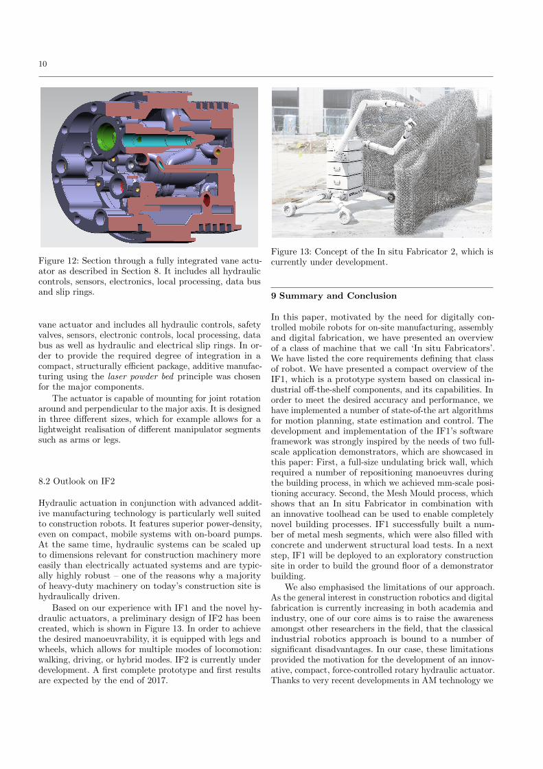
Figure 12: Section through a fully integrated vane actu-ator as described in Section 8. It includes all hydrauliccontrols, sensors, electronics, local processing, data busand slip rings.
vane actuator and includes all hydraulic controls, safetyvalves, sensors, electronic controls, local processing, databus as well as hydraulic and electrical slip rings. In or-der to provide the required degree of integration in acompact, structurally efficient package, additive manufac-turing using the laser powder bed principle was chosenfor the major components.
The actuator is capable of mounting for joint rotationaround and perpendicular to the major axis. It is designedin three different sizes, which for example allows for alightweight realisation of different manipulator segmentssuch as arms or legs.
8.2 Outlook on IF2
Hydraulic actuation in conjunction with advanced addit-ive manufacturing technology is particularly well suitedto construction robots. It features superior power-density,even on compact, mobile systems with on-board pumps.At the same time, hydraulic systems can be scaled upto dimensions relevant for construction machinery moreeasily than electrically actuated systems and are typic-ally highly robust – one of the reasons why a majorityof heavy-duty machinery on today’s construction site ishydraulically driven.
Based on our experience with IF1 and the novel hy-draulic actuators, a preliminary design of IF2 has beencreated, which is shown in Figure 13. In order to achievethe desired manoeuvrability, it is equipped with legs andwheels, which allows for multiple modes of locomotion:walking, driving, or hybrid modes. IF2 is currently underdevelopment. A first complete prototype and first resultsare expected by the end of 2017.
Figure 13: Concept of the In situ Fabricator 2, which iscurrently under development.
9 Summary and Conclusion
In this paper, motivated by the need for digitally con-trolled mobile robots for on-site manufacturing, assemblyand digital fabrication, we have presented an overviewof a class of machine that we call ‘In situ Fabricators’.We have listed the core requirements defining that classof robot. We have presented a compact overview of theIF1, which is a prototype system based on classical in-dustrial off-the-shelf components, and its capabilities. Inorder to meet the desired accuracy and performance, wehave implemented a number of state-of-the art algorithmsfor motion planning, state estimation and control. Thedevelopment and implementation of the IF1’s softwareframework was strongly inspired by the needs of two full-scale application demonstrators, which are showcased inthis paper: First, a full-size undulating brick wall, whichrequired a number of repositioning manoeuvres duringthe building process, in which we achieved mm-scale posi-tioning accuracy. Second, the Mesh Mould process, whichshows that an In situ Fabricator in combination withan innovative toolhead can be used to enable completelynovel building processes. IF1 successfully built a num-ber of metal mesh segments, which were also filled withconcrete and underwent structural load tests. In a nextstep, IF1 will be deployed to an exploratory constructionsite in order to build the ground floor of a demonstratorbuilding.
We also emphasised the limitations of our approach.As the general interest in construction robotics and digitalfabrication is currently increasing in both academia andindustry, one of our core aims is to raise the awarenessamongst other researchers in the field, that the classicalindustrial robotics approach is bound to a number ofsignificant disadvantages. In our case, these limitationsprovided the motivation for the development of an innov-ative, compact, force-controlled rotary hydraulic actuator.Thanks to very recent developments in AM technology we

11
are enabled to use highly integrated compact actuators inconjunction with very efficient additively manufacturedstructural components. We concluded this work by intro-ducing the concept for IF2, the next-generation In SituFabricator. We expect that this development is going tobe a major step towards facilitating advances in full-scaleconstruction robots.
References
1. Andres, J., Bock, T., Gebhart, F.: First Results of theDevelopment of the Masonry Robot System ROCCO. In:Proceedings of the 11th ISARC in Brighton (Interna-tional Symposium on Automation and Robotics in Con-struction), pp. 87–93 (1994)
2. Ardiny, H., Witwicki, S.J., Mondada, F.: Are Autonom-ous Mobile Robots Able to Take Over Construction? aReview. International Journal of Robotics 4(3), 10–21(2015)
3. Bonin-Font, F., Ortiz, A., Oliver, G.: Visual navigationfor mobile robots: A survey. Journal of intelligent androbotic systems 53(3), 263–296 (2008)
4. Bosscher, P., Williams, R.L., Bryson, L.S., Castro-Lacouture, D.: Cable-suspended robotic contour craftingsystem. Automation in Construction 17(1), 45–55 (2007)
5. Dorfler, K., Sandy, T., Giftthaler, M., Gramazio, F.,Kohler, M., Buchli, J.: Mobile Robotic Brickwork - Auto-mation of a Discrete Robotic Fabrication Process Usingan Autonomous Mobile Robot. In: Robotic Fabricationin Architecture, Art and Design, pp. 205–217 (2016)
6. Eppinger, S., Seering, W.: On dynamic models of robotforce control. In: IEEE International Conference on Ro-botics and Automation (ICRA), vol. 3, pp. 29–34 (1986)
7. Eppinger, S., Seering, W.: Understanding bandwidth lim-itations in robot force control. In: IEEE InternationalConference on Robotics and Automation (ICRA), vol. 4,pp. 904–909 (1987)
8. Giftthaler, M., Farshidian, F., Sandy, T., Stadelmann,L., Buchli, J.: Efficient Kinematic Planning for MobileManipulators with Non-holonomic Constraints Using Op-timal Control. In: IEEE International Conference on Ro-botics and Automation (ICRA), submitted (2017)
9. Hack, N., Lauer, W.V., Gramazio, F., Kohler, M.: MeshMould: Robotically Fabricated Metal Meshes as Con-crete Formwork and Reinforcement. In: FERRO-11: Pro-ceedings of the 11th International Symposium on Fer-rocement and 3rd ICTRC International Conference onTextile Reinforced Concrete, pp. 347–359. RILEM Pub-lications SARL, Bagneux (2015)
10. Helm, V., Ercan, S., Gramazio, F., Kohler, M.: Mobilerobotic fabrication on construction sites: Dimrob. In:2012 IEEE/RSJ International Conference on IntelligentRobots and Systems (IROS) (2012)
11. Howard, R.D.: Joint and actuator design for enhancedstability in robotic force control. Ph.D. thesis, Massachu-setts Institute of Technology (1990)
12. Jokic, S., Novikov, P., Maggs, S., Sadan, D., Jin, S., Nan,C.: Minibuilders. In: Architectural Principles, Tools, andProcesses, pp. 259–265. Digital Vernaclar (2015)
13. Kalakrishnan, M., Chitta, S., Theodorou, E., Pastor, P.,Schaal, S.: Stomp: Stochastic trajectory optimization formotion planning. In: IEEE International Conference onRobotics and Automation (ICRA), pp. 4569–4574 (2011)
14. Keating, S.: From Bacteria to Buildings: Additive Manu-facturing Outside the Box. Ph.D. thesis, MassachusettsInstitute of Technology (2016)
15. Khoshnevis, B.: Automated construction by contourcraftingrelated robotics and information technologies.Automation in construction 13(1), 5–19 (2004)
16. Kumar, N., Hack, N., Dorfler, K., Walzer, A., Rey, G.,Gramazio, F., Kohler, M., Buchli, J.: Design, Develop-ment and Experimental Assessment of a Robotic End-effector for Non-standard Concrete Applications. In:IEEE International Conference on Robotics and Auto-mation (ICRA), submitted (2017)
17. LaValle, S.M.: Planning algorithms. Cambridge univer-sity press (2006)
18. Olson, E.: AprilTag: A robust and flexible visual fiducialsystem. In: Proceedings of the IEEE International Con-ference on Robotics and Automation (ICRA), pp. 3400–3407. IEEE (2011)
19. Pritschow, G., Dalacker, M., Kurz, J., Gaenssle, M.: Tech-nological aspects in the development of a mobile brick-laying robot. Automation in Construction 5(1), 3 – 13(1996)
20. Quigley, M., Conley, K., Gerkey, B.P., Faust, J., Foote,T., Leibs, J., Wheeler, R., Ng, A.Y.: Ros: an open-sourcerobot operating system. In: ICRA Workshop on OpenSource Software (2009)
21. Rhinoceros, G.: Grasshopper Rhinoceros.http://http://www.grasshopper3d.com/ (2016). [Online;accessed 06-Nov-2016]
22. Sandy, T., Giftthaler, M., Dorfler, K., Kohler, M., Buchli,J.: Autonomous repositioning and localization of an InSitu Fabricator. In: IEEE International Conference onRobotics and Automation (ICRA), pp. 2852–2858 (2016)
23. Scaramuzza, D., Fraundorfer, F.: Visual odometry [tu-torial]. IEEE Robotics & Automation Magazine 18(4),80–92 (2011)
24. Semini, C., Baker, M., Laxman, K., Chandan, V.,Maruthiram, T., Robert Morgan, R., Frigerio, M.,Barasuol, V., Caldwell, D.G., Rey, G.: A Brief Over-view of a Novel, Highly-Integrated Hydraulic Servo Ac-tuator with Additive-Manufactured Titanium Body. In:IEEE/RSJ IROS Workshop on Force/Torque ControlledActuation (2016)
25. Thrun, S., et al.: Robotic mapping: A survey. Explor-ing artificial intelligence in the new millennium 1, 1–35(2002)
26. Willmann, J., Knauss, M., Bonwetsch, T., Apolinarska,A.A., Gramazio, F., Kohler, M.: Robotic timber construc-tion expanding additive fabrication to new dimensions.Automation in Construction 61, 16 – 23 (2016)
27. Xenomai: Xenomai: Real-Time Framework for Linux.http://www.xenomai.org (2016). [Online; accessed 06-Nov-2016]