kavs - ge grid solutions · kavs 100 user manual synchronism check relay publication reference:...
TRANSCRIPT
GE Energy Connections Grid Solutions
KAVS 100
User Manual Synchronism Check Relay
Publication reference: R8506I

HANDLING OF ELECTRONIC EQUIPMENT
A person’s normal movements can easily generate electrostatic potentials of several thousand volts. Discharge of these voltages into semiconductor devices when handling circuits can cause serious damage, which often may not be immediately apparent but the reliability of the circuit will have been reduced.
The electronic circuits of General Electric products are immune to the relevant levels of electrostatic discharge when housed in their cases. Do not expose them to the risk of damage by withdrawing modules unnecessarily.
Each module incorporates the highest practicable protection for its semiconductor devices. However, if it becomes necessary to withdraw a module, the following precautions should be taken to preserve the high reliability and long life for which the equipment has been designed and manufactured.
1. Before removing a module, ensure that you are a same electrostatic potential as the equipment by touching the case.
2. Handle the module by its front-plate, frame, or edges of the printed circuit board. Avoid touching the electronic components, printed circuit track or connectors.
3. Do not pass the module to any person without first ensuring that you are both at the same electrostatic potential. Shaking hands achieves equipotential.
4. Place the module on an antistatic surface, or on a conducting surface which is at the same potential as yourself.
5. Store or transport the module in a conductive bag.
More information on safe working procedures for all electronic equipment can be found in BS5783 and IEC 60147-0F.
If you are making measurements on the internal electronic circuitry of an equipment in service, it is preferable that you are earthed to the case with a conductive wrist strap.
Wrist straps should have a resistance to ground between 500k – 10M ohms. If a wrist strap is not available you should maintain regular contact with the case to prevent the build up of static. Instrumentation which may be used for making measurements should be earthed to the case whenever possible.
General Electric strongly recommends that detailed investigations on the electronic circuitry, or modification work, should be carried out in a Special Handling Area such as described in BS5783 or IEC 60147-0F.

CONTENT
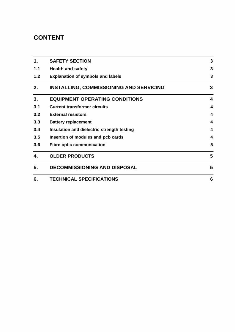
1. SAFETY SECTION 3 1.1 Health and safety 3 1.2 Explanation of symbols and labels 3
2. INSTALLING, COMMISSIONING AND SERVICING 3
3. EQUIPMENT OPERATING CONDITIONS 4 3.1 Current transformer circuits 4 3.2 External resistors 4 3.3 Battery replacement 4 3.4 Insulation and dielectric strength testing 4 3.5 Insertion of modules and pcb cards 4 3.6 Fibre optic communication 5
4. OLDER PRODUCTS 5
5. DECOMMISSIONING AND DISPOSAL 5
6. TECHNICAL SPECIFICATIONS 6


1. SAFETY SECTION
This Safety Section should be read before commencing any work on the equipment.
1.1 Health and safety
The information in the Safety Section of the product documentation is intended to ensure that products are properly installed and handled in order to maintain them in a safe condition. It is assumed that everyone who will be associated with the equipment will be familiar with the contents of the Safety Section.
1.2 Explanation of symbols and labels
The meaning of symbols and labels may be used on the equipment or in the product documentation, is given below.
Caution: refer to product documentation Caution: risk of electric shock
Protective/safety *earth terminal Functional *earth terminal
Note: This symbol may also be used for a protective/safety earth terminal if that terminal is part of a terminal block or sub-assembly e.g. power supply.
*NOTE: THE TERM EARTH USED THROUGHOUT THE PRODUCT DOCUMENTATION IS THE
DIRECT EQUIVALENT OF THE NORTH AMERICAN TERM GROUND.
2. INSTALLING, COMMISSIONING AND SERVICING
Equipment connections
Personnel undertaking installation, commissioning or servicing work on this equipment should be aware of the correct working procedures to ensure safety. The product documentation should be consulted before installing, commissioning or servicing the equipment.
Terminals exposed during installation, commissioning and maintenance may present a hazardous voltage unless the equipment is electrically isolated.
If there is unlocked access to the rear of the equipment, care should be taken by all personnel to avoid electrical shock or energy hazards.
Voltage and current connections should be made using insulated crimp terminations to ensure that terminal block insulation requirements are maintained for safety. To ensure that wires are correctly terminated, the correct crimp terminal and tool for the wire size should be used.
Before energising the equipment it must be earthed using the protective earth terminal, or the appropriate termination of the supply plug in the case of plug connected equipment. Omitting or disconnecting the equipment earth may cause a safety hazard.
The recommended minimum earth wire size is 2.5mm0, unless otherwise stated in the technical data section of the product documentation.
Before energising the equipment, the following should be checked:
− Voltage rating and polarity;
− CT circuit rating and integrity of connections;
− Protective fuse rating;
− Integrity of earth connection (where applicable)
− Remove front plate plastic film protection
− Remove insulating strip from battery compartment
3. EQUIPMENT OPERATING CONDITIONS
The equipment should be operated within the specified electrical and environmental limits.
3.1 Current transformer circuits
Do not open the secondary circuit of a live CT since the high level voltage produced may be lethal to personnel and could damage insulation.
3.2 External resistors
Where external resistors are fitted to relays, these may present a risk of electric shock or burns, if touched.
3.3 Battery replacement
Where internal batteries are fitted they should be replaced with the recommended type and be installed with the correct polarity, to avoid possible damage to the equipment.
3.4 Insulation and dielectric strength testing
Insulation testing may leave capacitors charged up to a hazardous voltage. At the end of each part of the test, the voltage should be gradually reduced to zero, to discharge capacitors, before the test leads are disconnected.
3.5 Insertion of modules and pcb cards
These must not be inserted into or withdrawn from equipment whist it is energised since this may result in damage.

3.6 Fibre optic communication
Where fibre optic communication devices are fitted, these should not be viewed directly. Optical power meters should be used to determine the operation or signal level of the device.
4. OLDER PRODUCTS
Electrical adjustments
Equipments which require direct physical adjustments to their operating mechanism to change current or voltage settings, should have the electrical power removed before making the change, to avoid any risk of electrical shock.
Mechanical adjustments
The electrical power to the relay contacts should be removed before checking any mechanical settings, to avoid any risk of electric shock.
Draw out case relays
Removal of the cover on equipment incorporating electromechanical operating elements, may expose hazardous live parts such as relay contacts.
Insertion and withdrawal of extender cards
When using an extender card, this should not be inserted or withdrawn from the equipment whilst it is energised. This is to avoid possible shock or damage hazards. Hazardous live voltages may be accessible on the extender card.
Insertion and withdrawal of heavy current test plugs
When using a heavy current test plug, CT shorting links must be in place before insertion or removal, to avoid potentially lethal voltages.
5. DECOMMISSIONING AND DISPOSAL
Decommissioning: The auxiliary supply circuit in the relay may include capacitors across the supply or to earth. To avoid electric shock or energy hazards, after completely isolating the supplies to the relay (both poles of any dc supply), the capacitors should be safely discharged via the external terminals prior to decommissioning.
Disposal: It is recommended that incineration and disposal to water courses is avoided. The product should be disposed of in a safe manner. Any products containing batteries should have them removed before disposal, taking precautions to avoid short circuits. Particular regulations within the country of operation, may apply to the disposal of lithium batteries.

6. TECHNICAL SPECIFICATIONS
Protective fuse rating
The recommended maximum rating of the external protective fuse for this equipment is 16A, Red Spot type or equivalent, unless otherwise stated in the technical data section of the product documentation.
Insulation class: IEC 601010-1 : 1990/A2 : 2001 Class I EN 61010-1: 2001 Class I
This equipment requires a protective (safety) earth connection to ensure user safety.
Insulation Category (Overvoltage):
IEC 601010-1 : 1990/A2 : 1995 Category III EN 61010-1: 2001 Category III
Distribution level, fixed insulation. Equipment in this category is qualification tested at 5kV peak, 1.2/50µs, 500Ω, 0.5J, between all supply circuits and earth and also between independent circuits.
Environment: IEC 601010-1 : 1990/A2 : 1995 Pollution degree 2
EN 61010-1: 2001 Pollution degree 2
Compliance is demonstrated by reference to generic safety standards.
Product Safety: 72/23/EEC
EN 61010-1: 2001 EN 60950-1: 2002
Compliance with the European Commission Low Voltage Directive.
Compliance is demonstrated by reference to generic safety standards.

Service Manual R8506I
KAYS 100
CONTENTS
1. HANDLING AND INSTALLATION 1
1.1 General considerations 1
1.1.1 Receipt of relays 1
1.1.2 Electrostatic discharge (ESD) 1
1.2 Handling of electronic equipment 1
1.3 Relay mounting 2
1.4 Unpacking 2
1.5 Storage 2
2. DESCRIPTION 3
2.1 Application 3
2.2 Main Operating Features 3
2.2.1 Synchronism check start/inhibit inputs 3
2.2.2 System split inhibit input 3
2.2.3 Dead line/live bus, live line/dead bus & dead line/dead bus inhibit inputs 3
2.2.4 "Inhibit" inputs selectable functionality 4
2.2.5 Undervoltage and differential voltage outputs selectable functionality 4
2.2.6 "Check synchronising" and "system synchronising" 4
2.2.7 Phase Angle & System Angle check inhibit by System Split 5
2.3 Opto isolated inputs 5
2.4 User Inputs 6
2.5 Output Relays 6
2.6 Control Outputs 7
2.7 Plant Status Output 7
2.8 Software Logic Functions 7
2.9 Timer Setting Ranges 9
2.10 Counters 9
2.11 Scheme Alarms and Indications 9
2.12 Disturbance recorder triggers 10
2.13 Scheme Event Records 11
2.14 Synchronism Check/Voltage Monitor 11
2.15 Measurement 13
2.16 Alarms 15
2.16.1 Scheme alarms 15
2.16.2 Self monitoring alarms 15
2.16.3 Watchdog test feature 16
R8506I Service Manual
KAYS 100
2.17 Password protection 16
2.18 Serial communication 16
2.18.1 Time tagged event records 17
2.18.2 Disturbance Records 17
2.18.3 Remote control functions 18
2.18.4 Notes on serial port 18
2.18.5 Notes on security of remote control via the serial port 18
3. EXTERNAL CONNECTIONS 19
3.1 Auxiliary supply 20
3.2 Opto-isolated control inputs 20
3.3 Analogue inputs 20
3.4 Output relays 21
3.5 Serial communication port (K-Bus) 21
4. USER INTERFACE 22
4.1 Front plate layout 22
4.2 LED indications 22
4.3 Keypad 23
4.4 Liquid crystal display 23
5. MENU SYSTEM 24
5.1 Menu contents 25
5.1.1 System Data 25
5.1.2 User Controls [SET] 27
5.1.3 Control Outputs [READ] 27
5.1.4 Event Records [READ] 27
5.1.5 Measurements [READ] 28
5.1.6 Counter Yalues [READ] 28
5.1.7 Scheme Alarms [READ] 28
5.1.8 Check Synch Stgs [SET] 28
5.1.9 Timer Settings [SET] 30
5.1.10 Counter Settings [SET] 30
5.1.11 Logic Functions [SET] 30
5.1.12 Input Masks [PWP] 30
5.1.13 Relay Masks [PWP] 31
5.1.14 Counter Resets [SET] 31
5.1.15 Recorder (see also Section 5.3) 31
5.2 Changing text and settings 31
5.2.1 Entering passwords (SYS Password cell) 32

Service Manual R8506I
KAYS 100
5.2.2 Changing passwords 32
5.2.3 Entering text 32
5.2.4 Changing function links 32
5.2.5 Changing setting values 33
5.2.6 Setting communication address 33
5.2.7 Setting input masks and relay masks 33
5.2.8 Resetting counter registers 33
5.2.9 Alarm records 34
5.2.10 Default display (LCD) 34
5.3 Disturbance recorders 34
5.3.1 Recorder control 34
5.3.2 Recorder capture 35
5.3.3 Recorder post trigger 35
5.3.4 Recorder logic triggers 35
5.3.5 Notes on recorded times 35
6. SCHEME LOGIC 36
6.1 Ladder logic: general description 36
6.2 Ladder logic: element identification 36
6.2.1 Inputs 36
6.2.2 Outputs and software relays 36
6.2.3 Software scheme function links 37
6.2.4 Other elements 37
7. TECHNICAL DATA 46
7.1 Ratings 46
7.1.1 Outputs 46
7.2 Burdens 46
7.2.1 Yoltage circuits 46
7.2.2 Auxiliary voltage 46
7.2.3 Opto-isolated inputs 47
7.3 Setting ranges 47
7.3.1 Autoreclose settings 47
7.3.2 Check synchronism settings 47
7.3.3 Measurement (displayed) 48
7.3.4 Ratios 48
7.4 Accuracy 49
7.4.1 General for reference conditions 49
7.4.2 Influencing quantities 50
7.5 Opto-isolated control inputs 50

R8506I Service Manual
KAYS 100
7.6 Contacts 50
7.7 Operation indicator 51
7.8 Communication port 51
7.9 High voltage withstand 51
7.9.1 Insulation 51
7.9.2 Impulse IEC60255-5 51
7.9.3 High frequency disturbance IEC60255-22-1/2 51
7.9.4 Fast transient IEC60255-22-4 51
7.9.5 Static discharge test 52
7.9.6 ANSI/IEEE standards C36.90 52
7.10 Environmental 52
7.10.1 Temperature IEC60068-2-3 52
7.10.2 Humidity IEC60068-2-3 52
7.10.3 Enclosure protection IEC60529 52
7.10.4 Yibration IEC255-21-1 52
7.10.5 Mechanical durability 52
7.11 Model numbers 52
8. COMMISSIONING 54
8.1 Commissioning preliminaries 54
8.1.1 Quick guide to local menu control 54
8.1.1.1 With the cover fitted to the case 54
8.1.1.2 With the cover removed from the case 55
8.1.2 Terminal allocation 55
8.1.3 Electrostatic discharge (ESD) 55
8.1.4 Inspection 55
8.1.5 Earthing 56
8.1.6 Main current transformers 56
8.1.7 Test block 56
8.1.8 Insulation 56
8.2 Commissioning test notes 56
8.2.1 Equipment required: 56
8.3 Auxiliary supply tests 57
8.3.1 Auxiliary supply 57
8.3.2 Energisation from auxiliary voltage supply 57
8.3.3 Field voltage 57
8.4 Measurement checks 58
8.5 Opto-input checks 58
8.6 Output relay checks 59

Service Manual R8506I
KAYS 100
8.7 Synchronism check elements 59
8.7.1 Phase angle check - instantaneous operation. (Monitor RL0, terminals 30-32). 60
8.7.2 Phase angle check - delay on operation. (Monitor RL0, terminals 30-32). 60
8.7.3 Phase angle check - undervoltage blocking. (Monitor RL0, terminals 30-32, and RL5, terminals 33-35). 60
8.7.4 Phase angle check - differential voltage blocking. (Monitor RL0, terminals 30-32, and RL6, terminals 37-39). 60
8.7.5 System angle check - instantaneous operation. (Monitor RL1, terminals 34-36). 61
8.7.6 System angle check - delay on operation. (Monitor RL1, terminals 34-36). 61
8.7.7 System angle check - undervoltage blocking. (Monitor RL1, terminals 34-36, and RL5, terminals 33-35). 61
8.7.8 System angle check - differential voltage blocking. (Monitor RL1, terminals 34-36, and RL6, terminals 37-39). 62
8.8 Voltage monitor elements. 62
8.8.1 Dead line/live bus monitor. 62
8.8.2 Live line/dead bus monitor. 63
8.8.3 Dead line/dead bus monitor. 63
8.9 System split detector. 63
8.9.1 Instantaneous reset. (Monitor RL7, terminals 41-43). 63
8.9.2 Minimum output pulse. (Monitor RL7, terminals 41-43). 63
8.10 Final settings 63
9. PROBLEM SOLVING 64
9.1 Password lost or not accepted 64
9.2 Check synchronism settings 64
9.2.1 Cells not visible 64
9.2.2 Undervoltage feature does not block 65
9.2.3 Differential voltage feature does not block 65
9.2.4 Undervoltage feature output has incorrect sense 65
9.2.5 Differential voltage feature output has incorrect sense 65
9.2.6 Function links cannot be changed 65
9.3 Alarms 65
9.3.1 Watchdog alarm 65
9.3.2 Unconfigured or uncalibrated alarm 65
9.3.3 Setting error alarm 66
9.3.4 "No Service" alarm 66
9.4 Records 66
9.4.1 Problems with event records 66
9.5 Communications 66
9.5.1 Measured values do not change 66

R8506I Service Manual
KAYS 100
9.5.2 Relay no longer responding 67
9.5.3 No response to remote control commands 67
10. MAINTENANCE 67
10.1 Testing 67
10.1.1 Alarms 67
10.1.2 Measurement accuracy 67
10.1.3 Output relay test 67
10.2 Additional tests 68
10.3 Method of repair 68
10.3.1 Replacing a PCB 68
10.3.2 Replacing output relays and opto-isolators 69
10.3.3 Replacing the power supply board 69
10.3.4 Replacing the back plane (size 4 & 6 case) 69
10.4 Recalibration 69
10.5 Return to factory 69
11. Commissioning Test Record 70
12. KAVS100 SOFTWARE HISTORY 76
Figure 1: Response of Fourier filtering 14
Figure 2: Frequency response for single voltage input 15
Figure 3: Connection to opto-isolated control inputs 20
Figure 4: Terminal arrangement for communications 21
Figure 5: Front plate layout 22
Figure 6: Menu system of relay 24
Figure 7: Scheme logic diagram: KAYS100 (Drg. No 08KAYS10001) 37
Figure 8: Scheme logic diagram: KAYS100 (Drg. No 08 KAYS10001) 38
Figure 9: Scheme logic diagram: KAYS100 (Drg. No 08KAYS10001) 39
Figure 10: Scheme logic diagram: KAYS100 (Drg. No 08KAYS10001) 40
Figure 11: Scheme logic diagram: KAYS100 008 (Drg. No 08KAYS10001) 41
Figure 12: Relay settings: Type KAYS100 (Standard factory settings) 42
Figure 13: 08 KAXX 00 Sheet 1 43
Figure 14: 08 KAXX 00 Sheet 2 44
Figure 15: Typical application diagram: Midos check synchronising relay type KAYS 100 45

Service Manual R8506I
KAYS 100 Page 1/80
1. HANDLING AND INSTALLATION
1.1 General considerations
1.1.1 Receipt of relays
Protective and control relays, although generally of robust construction, require careful treatment prior to installation on site. Upon receipt, relays should be examined immediately, to ensure no damage has been sustained in transit. If damage has been sustained during transit, a claim should be made to the transport contractor, and a General Electric representative should be promptly notified.
Relays that are supplied unmounted and not intended for immediate installation should be returned to their protective polythene bags.
1.1.2 Electrostatic discharge (ESD)
The relays use components that are sensitive to electrostatic discharges. The electronic circuits are well protected by the metal case and the internal module should not be withdrawn unnecessarily. When handling the module outside its case, care should be taken to avoid contact with components and electrical connections. If removed from the case for storage, the module should be placed in an electrically conducting anti static bag.
There are no setting adjustments within the module and it is advised that it is not unnecessarily disassembled. Although the printed circuit boards are plugged together, the connectors are a manufacturing aid and not intended for frequent dismantling; in fact considerable effort may be required to separate them. Touching the printed circuit board should be avoided, since complementary metal oxide semiconductors (CMOS) are used, which can be damaged by static electricity discharged from the body.
1.2 Handling of electronic equipment
A person's normal movements can easily generate electrostatic potentials of several thousand volts. Discharge of these voltages into semiconductor devices when handling electronic circuits can cause serious damage, which often may not be immediately apparent but the reliability of the circuit will have been reduced.
The electronic circuits are completely safe from electrostatic discharge when housed in the case. Do not expose them to risk of damage by withdrawing modules unnecessarily.
Each module incorporates the highest practicable protection for its semiconductor devices. However, if it becomes necessary to withdraw a module, the precautions should be taken to preserve the high reliability and long life for which the equipment has been designed and manufactured.
1. Before removing a module, ensure that you are at the same electrostatic potential as the equipment by touching the case.
2. Handle the module by its front plate, frame or edges of the printed circuit board. Avoid touching the electronic components, printed circuit track or connectors.
3. Do not pass the module to another person without first ensuring you are both at the same electrostatic potential. Shaking hands achieves equipotential.
4. Place the module on an anti static surface, or on a conducting surface which is at the same potential as yourself.

R8506I Service Manual
Page 2/80 KAYS 100
5. Store or transport the module in a conductive bag.
If you are making measurements on the internal electronic circuitry of an equipment in service, it is preferable that you are earthed to the case with a conductive wrist strap. Wrist straps should have a resistance to ground between 500k-10M. If a wrist strap is not available, you should maintain regular contact with the case to prevent a build-up of static. Instrumentation which may be used for making measurements should be earthed to the case whenever possible.
More information on safe working procedures for all electronic equipment can be found in BS5783 and IEC 60147-OF. It is strongly recommended that detailed investigations on electronic circuitry, or modification work, should be carried out in a Special Handling Area such as described in the afore-mentioned BS and IEC documents.
1.3 Relay mounting
Relays are dispatched, either individually, or as part of a panel/rack assembly. If loose relays are to be assembled into a scheme, then construction details can be found in publication R7012. If an MMLG test block is to be included it should be positioned at the right hand side of the assembly (viewed from the front). Modules should remain protected by their metal case during assembly into a panel or rack. The design of the relay is such that the fixing holes are accessible without removal of the cover. For individually mounted relays, an outline diagram is normally supplied showing the panel cut-outs and hole centres. These dimensions will also be found in publication R6003.
1.4 Unpacking
Care must be taken when unpacking and installing the relays so that none of the parts is damaged, or the settings altered and they must at all times be handled by skilled persons only. The installation should be clean, dry and reasonably free from dust and excessive vibration. The site should be well lit to facilitate inspection. Relays that have been removed from their cases should not be left in situations where they are exposed to dust or damp. This particularly applies to installations which are being carried out at the same time as construction work.
1.5 Storage
If relays are not to be installed immediately on receipt they should be stored in a place free from dust and moisture in their original cartons. Where de-humidifier bags have been included in the packing they should be retained. The action of the de-humidifier crystals will be impaired if the bag has been exposed to ambient conditions and may be restored by gently heating the bag for about an hour, prior to replacing it in the carton.
Dust which collects on a carton may, on subsequent unpacking, find its way into the relay; in damp conditions the carton and packing may become impregnated with moisture and the de-humidifier will lose its efficiency.
Storage temperature -25°C to +70°C.

Service Manual R8506I
KAYS 100 Page 3/80
2. DESCRIPTION
2.1 Application
The KAYS 100 is a free standing synchronism check and voltage monitor relay for use with auto-reclose and manual circuit breaker closing schemes. It incorporates two a.c. voltage measuring circuits, and various comparators which may be selected via the user interface to give output signals as required for specific applications.
The available comparators are described in detail under Synchronism Check/Yoltage Monitor. They are:-
− two functionally identical synchronism check comparators, Phase Angle and System Angle with independent "maximum angle", "limiting slip frequency" and "operating time" settings, which operate when the phase angle between line and bus voltages is less than the set "maximum angle", and certain other conditions are satisfied;
− system split, which operates when the phase angle between line and bus voltages exceeds the set "split angle", to indicate when the two systems are out of phase;
− dead line/live bus, which operates when the measured line voltage is less than a set "dead circuit" value and the measured bus voltage is greater than a set "live circuit" value;
− live line/dead bus, which operates when the measured bus voltage is less than a set "dead circuit" value and the measured line voltage is greater than a set "live circuit" value;
− dead line/dead bus, which operates when the measured line and bus voltages are both less than a set "dead circuit" value;
− undervoltage, which operates when the measured magnitude of either line or bus voltage is less than a set "undervoltage" value;
− differential voltage, which operates when the arithmetic difference between the measured magnitudes of line and bus voltages is greater than a set "differential voltage" value.
2.2 Main Operating Features
2.2.1 Synchronism check start/inhibit inputs
The two synchronism check comparators can be configured by software scheme function link settings, to be either active only when specific "start ...syn" logic inputs are on or active when the logic inputs are off. The choice of operating mode will depend largely on the individual preference of the end user: some utilities prefer to activate a synchronism check relay only when a check is required, i.e. when an auto- reclose cycle or manual CB closing is in progress. Two scheme logic inputs are provided to "start" the sychronism check comparators independently.
2.2.2 System split inhibit input
The system split comparator can be temporarily inhibited (de-selected) by a scheme logic input.
2.2.3 Dead line/live bus, live line/dead bus & dead line/dead bus inhibit inputs
The DLLB, LLDB and DLDB comparators are always active, and operate individual "unqualified" scheme logic outputs, which may be used for indication purposes, or simply ignored. Each of these comparators also operates two "qualified" scheme

R8506I Service Manual
Page 4/80 KAYS 100
logic outputs, intended for auto-reclose and manual CB closing supervision. Each "qualified" output can be temporarily inhibited (de-selected) by a dedicated scheme logic input.
These inhibit inputs, along with the synchronism check inhibit inputs, allow the "permission to close" conditions for auto-reclosing and manual CB closing to be selected or modified by external signals from a separate control point to relay opto inputs.
2.2.4 "Inhibit" inputs selectable functionality
The functionality of all the "inhibit" inputs is collectively selectable by a software scheme function link setting to either:-
i. off to enable/on to inhibit the associated comparator or output;
or
ii. on to enable/off to inhibit the associated comparator or output
2.2.5 Undervoltage and differential voltage outputs selectable functionality
The functionality of the outputs from the undervoltage and differential voltage comparators are individually selectable by software check synchronism function links settings to either:-
i. on when specified condition is true/off when condition is not true;
or
ii. off when specified condition is true/on when condition is not true.
2.2.6 "Check synchronising" and "system synchronising"
If FNCT 7 (Auto Sys Syn) is set to 0, the Phase Angle and System Angle checks operate independently. In many applications, only one set of synchro check parameters will be required in all circumstances, in which case, either of the comparators can be applied and the other can be ignored. In a few applications, it might be useful to set two different sets of synchro check parameters (e.g. Phase Angle check with low slip and moderate phase angle, and System Angle check with moderate slip and small phase angle), and arrange output mask settings such that an output is given if either conditions are satisfied.
If FNCT 7 is set to 1, then, when line and bus volts are initially applied to the relay, it checks for phase angle, slip frequency, etc in line with selected "Phase Angle" settings (Check Synchchronising mode). If a System Split is detected before the Phase Angle settings are satisfied, the relay stops checking for Phase Angle settings and starts checking instead for "System Angle" settings (System Synchronising mode). This functionality is generally in line with that specified by a major national transmission utility.
When FNCT 7 is set to 1, it is possible to enable/disable two automatic reset mechanisms for automatically selected System Synch functionality, by setting function links FNCT 9 & 10, as described below.
If FNCT 9 (No Timeout SS) is set to 0, the relay will automatically cancel the System Synch mode if the selected System Synch conditions remain unsatisfied for a period which can be adjusted up to 9999 seconds (TMR SSyn MaxTime). If FNCT 9 is set to 1, the System Synch mode stays active until reset by removing the Line Y and/or Bus Y inputs.
If FNCT 10 (No Autoreset SS) is set to 0, the System Synch mode is cancelled after a short delay (TMR SSyn ResetTm, adjustable 0.01 to 9999 seconds), when the selected

Service Manual R8506I
KAYS 100 Page 5/80
System Synch conditions become satisfied and the System Synch output is given. If FNCT 10 is set to 1, the System Synch mode stays active until reset by removing the Line Y and/or Bus Y inputs.
2.2.7 Phase Angle & System Angle check inhibit by System Split
If FNCT 7 is set to 0 (i.e. no automatic switching between Check Synch and System Synch mode), and FNCT 8 (Split No Hold) is set to 0, operation of the System Split output sets a "HOLD" logic flag which inhibits operation of the Phase Angle and System Angle comparators. The HOLD flag remains set, and Phase Angle and System Angle inhibited, even after the System Split output resets, until: -
− the Line Y and/or Bus Y input goes dead, in which case the HOLD flag resets after a short delay (TMR Split Dly DO, adjustable 0.01 to 9999 seconds), or
− the HOLD condition is reset by pressing the [0] key when the LCD prompt "Reset Alarms = [0]" is displayed.
If FNCT 8 is set to 1, the HOLD flag is blocked, and the Phase Angle and System Angle comparators are not inhibited by the System Split output. However, since the Phase/System Angle check and System Split conditions are mutually exclusive, a Phase/System Angle check output is impossible while a System Split condition is present.
2.3 Opto isolated inputs
KAYS relays have eight opto isolated inputs, with software filtering to prevent maloperation due to induced a.c. signals in the external wiring. KAYS 100 scheme logic has nine functional logic inputs. The inputs required for any specific application are selected by setting INPUT MASKS to assign one or more opto inputs to each required logic input. Although most selections are one to one, parallel mask settings are possible. A single opto input can activate more than one logic input, and a single logic input may be activated by more than one opto input.
The available functional logic inputs are described below. The default mask settings are listed in scheme logic diagram, drg. no. 08 KAYS100 01.
Display Name Effect in Scheme Logic with Input On
INP Start ChSyn Start synchronism check (phase angle).
INP Start SysSyn Start synchronism check (system angle).
INP Inh DLLB/ChS if FNCT 2 = 0 - inhibit DLLB output for auto-recl; if FNCT 2 = 1 - enable DLLB output for auto-recl.
INP Inh LLDB/ChS if FNCT 2 = 0 - inhibit LLDB output for auto-recl; if FNCT 2 = 1 - enable LLDB output for auto-recl.
INP Inh DLDB/ChS if FNCT 2 = 0 - inhibit DLDB output for auto-recl; if FNCT 2 = 1 - enable DLDB output for auto-recl.
INP Inh DLLB/SyS if FNCT 2 = 0 - inhibit DLLB output for manual cl; if FNCT 2 = 1 - enable DLLB output for manual cl.
INP Inh LLDB/SyS if FNCT 2 = 0 - inhibit LLDB output for manual cl; if FNCT 2 = 1 - enable LLDB output for manual cl.
INP Inh DLDB/SyS if FNCT 2 = 0 - inhibit DLDB output for manual cl; if FNCT 2 = 1 - enable DLDB output for manual cl.
INP Inh SysSplit if FNCT 2 = 0 - inhibit system split comparator; if FNCT 2 = 1 - enable system split comparator.
R8506I Service Manual
Page 6/80 KAYS 100
2.4 User Inputs
KAYS 100 relay scheme logic does not include any user inputs.
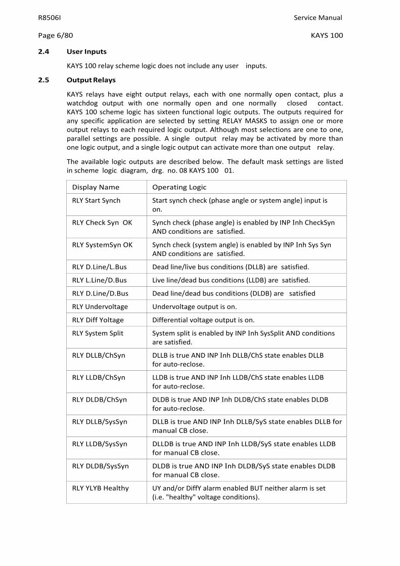
2.5 Output Relays
KAYS relays have eight output relays, each with one normally open contact, plus a watchdog output with one normally open and one normally closed contact. KAYS 100 scheme logic has sixteen functional logic outputs. The outputs required for any specific application are selected by setting RELAY MASKS to assign one or more output relays to each required logic output. Although most selections are one to one, parallel settings are possible. A single output relay may be activated by more than one logic output, and a single logic output can activate more than one output relay.
The available logic outputs are described below. The default mask settings are listed in scheme logic diagram, drg. no. 08 KAYS 100 01.
Display Name Operating Logic
RLY Start Synch Start synch check (phase angle or system angle) input is on.
RLY Check Syn OK Synch check (phase angle) is enabled by INP Inh CheckSyn AND conditions are satisfied.
RLY SystemSyn OK Synch check (system angle) is enabled by INP Inh Sys Syn AND conditions are satisfied.
RLY D.Line/L.Bus Dead line/live bus conditions (DLLB) are satisfied.
RLY L.Line/D.Bus Live line/dead bus conditions (LLDB) are satisfied.
RLY D.Line/D.Bus Dead line/dead bus conditions (DLDB) are satisfied
RLY Undervoltage Undervoltage output is on.
RLY Diff Yoltage Differential voltage output is on.
RLY System Split System split is enabled by INP Inh SysSplit AND conditions are satisfied.
RLY DLLB/ChSyn DLLB is true AND INP Inh DLLB/ChS state enables DLLB for auto-reclose.
RLY LLDB/ChSyn LLDB is true AND INP Inh LLDB/ChS state enables LLDB for auto-reclose.
RLY DLDB/ChSyn DLDB is true AND INP Inh DLDB/ChS state enables DLDB for auto-reclose.
RLY DLLB/SysSyn DLLB is true AND INP Inh DLLB/SyS state enables DLLB for manual CB close.
RLY LLDB/SysSyn DLLDB is true AND INP Inh LLDB/SyS state enables LLDB for manual CB close.
RLY DLDB/SysSyn DLDB is true AND INP Inh DLDB/SyS state enables DLDB for manual CB close.
RLY YLYB Healthy UY and/or DiffY alarm enabled BUT neither alarm is set (i.e. "healthy" voltage conditions).

Service Manual R8506I
KAYS 100 Page 7/80
2.6 Control Outputs
Twelve "control outputs" (see Sections 5.1.1 - cell 000D, and 5.1.3) are available for relay status indications through the user interface, as described below.
Display Name Operating Logic
CTL Start Synch Start synch check (phase angle or system angle) input is on.
CTL Check Syn OK Synch check (phase angle) is enabled by INP Inh
CheckSyn AND conditions are satisfied.
CTL SystemSyn OK Synch check (system angle) is enabled by INP Inh Sys Syn
AND conditions are satisfied.
CTL D.Line/L.Bus Dead line/live bus conditions (DLLB) are satisfied.
CTL L.Line/D.Bus Live line/dead bus conditions (LLDB) are satisfied.
CTL D.Line/D.Bus Dead line/dead bus conditions (DLDB) are satisfied
CTL Undervoltage Undervoltage output is on.
CTL Diff Yoltage Differential voltage output is on.
CTL System Split System split is enabled by INP Inh SysSplit AND conditions are satisfied.
CTL Auto Sys Syn System synchronising mode selected (see 2.2.6)
CTL Sync Blocked Synchro checks inhibited following system split (see 2.2.7)
CTL YLYB Healthy "Healthy" voltage conditions present (no UY or DiffY alarm).
2.7 Plant Status Output
No plant status outputs are used in KAYS 100 logic, and SYS Plant Status bits 0 to F are always 0.
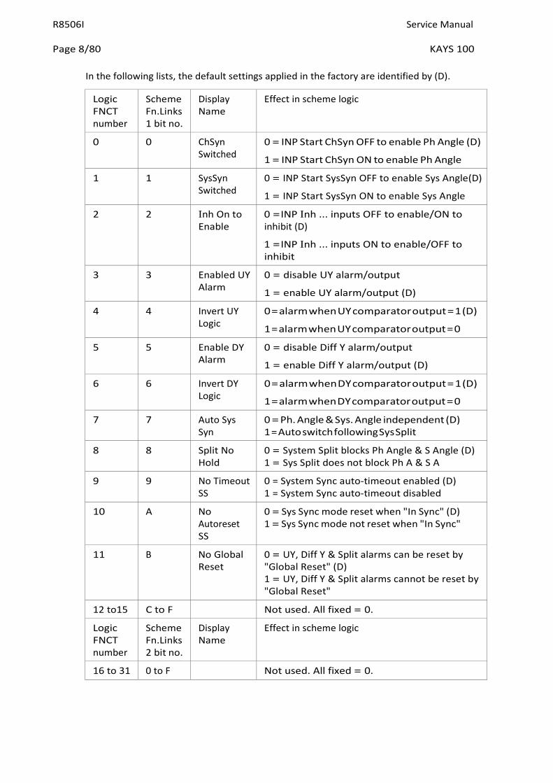
2.8 Software Logic Functions
KAYS 100 scheme logic can be user-configured to enable/disable selected features, as required for specific applications, by setting scheme function links to 0 or 1. Links are identified by:-
i. decimal numbering from FNCT 0 to FNCT 31 in ladder logic diagrams,
and
ii. hexadecimal numbering in two sixteen-bit words in LOGIC FUNCTIONS menu cells 0A01 and 0A02.
Cell 0A01 [Scheme Fn. Links 1] bits 0 to F correspond to FNCT 0 to 15.
Cell 0A02 [Scheme Fn. Links 2] bits 0 to F correspond to FNCT 16 to 31.
R8506I Service Manual
Page 8/80 KAYS 100
In the following lists, the default settings applied in the factory are identified by (D).
Logic FNCT number
Scheme Fn.Links 1 bit no.
Display Name
Effect in scheme logic
0 0 ChSyn Switched
0 = INP Start ChSyn OFF to enable Ph Angle (D)
1 = INP Start ChSyn ON to enable Ph Angle
1 1 SysSyn Switched
0 = INP Start SysSyn OFF to enable Sys Angle(D)
1 = INP Start SysSyn ON to enable Sys Angle
2 2 Inh On to Enable
0 = INP Inh ... inputs OFF to enable/ON to inhibit (D)
1 = INP Inh ... inputs ON to enable/OFF to inhibit
3 3 Enabled UY Alarm
0 = disable UY alarm/output
1 = enable UY alarm/output (D)
4 4 Invert UY Logic
0 = alarm when UY comparator output = 1 (D)
1 = alarm when UY comparator output = 0
5 5 Enable DY Alarm
0 = disable Diff Y alarm/output
1 = enable Diff Y alarm/output (D)
6 6 Invert DY Logic
0 = alarm when DY comparator output = 1 (D)
1 = alarm when DY comparator output = 0
7 7 Auto Sys Syn
0 = Ph. Angle & Sys. Angle independent (D) 1 = Auto switch following Sys Split
8 8 Split No Hold
0 = System Split blocks Ph Angle & S Angle (D) 1 = Sys Split does not block Ph A & S A
9 9 No Timeout SS
0 = System Sync auto-timeout enabled (D) 1 = System Sync auto-timeout disabled
10 A No Autoreset SS
0 = Sys Sync mode reset when "In Sync" (D) 1 = Sys Sync mode not reset when "In Sync"
11 B No Global Reset
0 = UY, Diff Y & Split alarms can be reset by "Global Reset" (D) 1 = UY, Diff Y & Split alarms cannot be reset by "Global Reset"
12 to15 C to F Not used. All fixed = 0.
Logic FNCT number
Scheme Fn.Links 2 bit no.
Display Name
Effect in scheme logic
16 to 31 0 to F Not used. All fixed = 0.
Service Manual R8506I
KAYS 100 Page 9/80
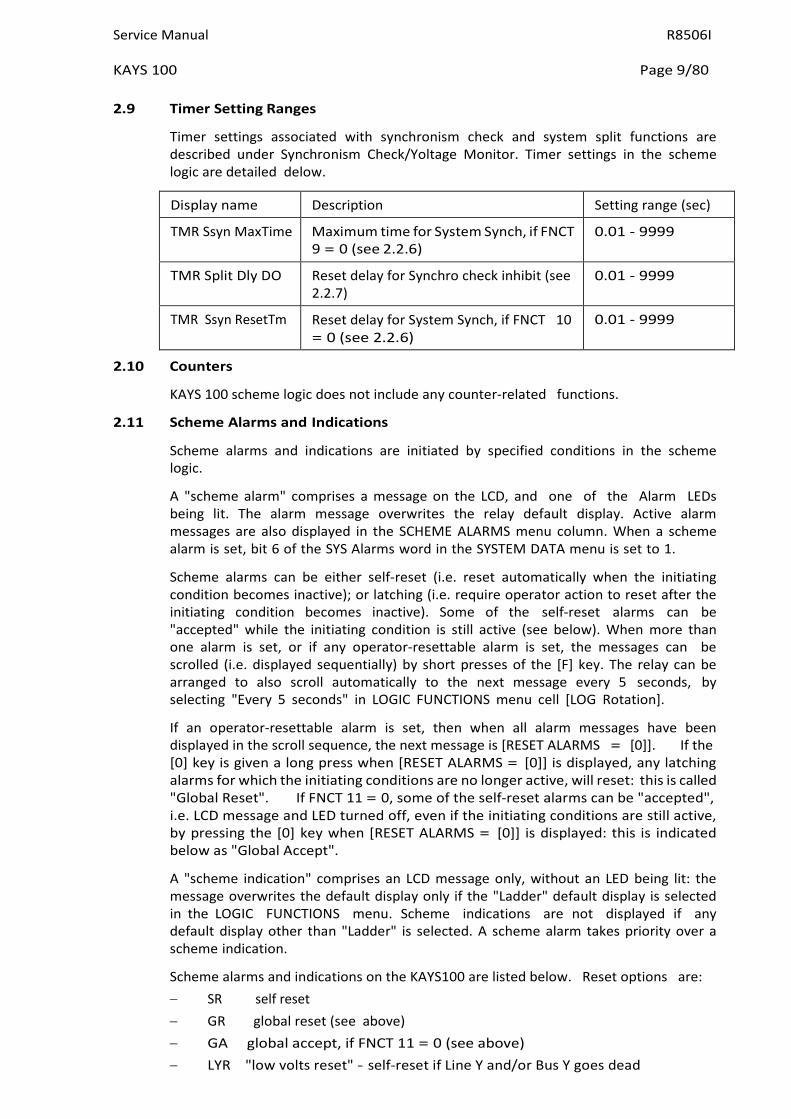
2.9 Timer Setting Ranges
Timer settings associated with synchronism check and system split functions are described under Synchronism Check/Yoltage Monitor. Timer settings in the scheme logic are detailed delow.
Display name Description Setting range (sec)
TMR Ssyn MaxTime Maximum time for System Synch, if FNCT 9 = 0 (see 2.2.6)
0.01 - 9999
TMR Split Dly DO Reset delay for Synchro check inhibit (see 2.2.7)
0.01 - 9999
TMR Ssyn ResetTm Reset delay for System Synch, if FNCT 10 = 0 (see 2.2.6)
0.01 - 9999
2.10 Counters
KAYS 100 scheme logic does not include any counter-related functions.
2.11 Scheme Alarms and Indications
Scheme alarms and indications are initiated by specified conditions in the scheme logic.
A "scheme alarm" comprises a message on the LCD, and one of the Alarm LEDs being lit. The alarm message overwrites the relay default display. Active alarm messages are also displayed in the SCHEME ALARMS menu column. When a scheme alarm is set, bit 6 of the SYS Alarms word in the SYSTEM DATA menu is set to 1.
Scheme alarms can be either self-reset (i.e. reset automatically when the initiating condition becomes inactive); or latching (i.e. require operator action to reset after the initiating condition becomes inactive). Some of the self-reset alarms can be "accepted" while the initiating condition is still active (see below). When more than one alarm is set, or if any operator-resettable alarm is set, the messages can be scrolled (i.e. displayed sequentially) by short presses of the [F] key. The relay can be arranged to also scroll automatically to the next message every 5 seconds, by selecting "Every 5 seconds" in LOGIC FUNCTIONS menu cell [LOG Rotation].
If an operator-resettable alarm is set, then when all alarm messages have been displayed in the scroll sequence, the next message is [RESET ALARMS = [0]]. If the [0] key is given a long press when [RESET ALARMS = [0]] is displayed, any latching alarms for which the initiating conditions are no longer active, will reset: this is called "Global Reset". If FNCT 11 = 0, some of the self-reset alarms can be "accepted", i.e. LCD message and LED turned off, even if the initiating conditions are still active, by pressing the [0] key when [RESET ALARMS = [0]] is displayed: this is indicated below as "Global Accept".
A "scheme indication" comprises an LCD message only, without an LED being lit: the message overwrites the default display only if the "Ladder" default display is selected in the LOGIC FUNCTIONS menu. Scheme indications are not displayed if any default display other than "Ladder" is selected. A scheme alarm takes priority over a scheme indication.
Scheme alarms and indications on the KAYS100 are listed below. Reset options are: − SR self reset − GR global reset (see above) − GA global accept, if FNCT 11 = 0 (see above) − LYR "low volts reset" - self-reset if Line Y and/or Bus Y goes dead

R8506I Service Manual
Page 10/80 KAYS 100
LCD Message LED Initiating condition Reset
Live Bus / Dead Line
None Live Bus/Dead Line output set (indication)
SR
Dead Bus / Live Line
None Dead Bus/Live Line output set (indication)
SR
Dead Bus / Dead Line
None Dead Bus/Dead Line output set (indication)
SR
In Synchronism (Check Synch)
Amber Phase Angle output set SR
In Synchronism (System Synch)
Amber System Angle output set SR
Undervoltage Red Undervoltage output set SR, GA
Differential Yoltage Red Differential voltage output set SR, GA
System Split Red System Split output set SR, GA
Synch blocked by sys split
Red Synch check inhibited following system split
LYR, GR
2.12 Disturbance recorder triggers
The disturbance recorder function is generally described in sections 2.18.2 and 5.3 of this manual. The KAYS100 does not have any analogue current inputs, and so cannot make full fault records. However, some users have found records of input and output operations and voltage waveforms helpful in analysing some system disturbances. Disturbance recorder triggers in the KAYS100 are listed below.
No. Name Effect if set to1 in cell REC Trig ON
0 Ch Syn Trigger Trigger when Phase Angle comparator operates
1 Sys Syn Trigger Trigger when System Angle comparator operates
2 DLLB Trigger Trigger when Dead Line/Live Bus comparator operates
3 LLDB Trigger Trigger when Live Line/Dead Bus comparator operates
4 DLDB Trigger Trigger when Dead Line/Dead Bus comparator operates
5 UY Trigger Trigger when Undervoltage comparator operates
6 DiffY Trigger Trigger when Diff Yoltage comparator operates
7 LLLB Trigger Trigger when LLLB flag operates (both Line Y and Bus Y inputs are "not dead")
8 SysSplit Trigger Trigger when System split comparator operates
No. Name Effect if set to1 in cell REC Trig OFF
0 Ch Syn Trigger Trigger when Phase Angle comparator resets
1 Sys Syn Trigger Trigger when System Angle comparator resets
2 DLLB Trigger Trigger when Dead Line/Live Bus comparator resets
3 LLDB Trigger Trigger when Live Line/Dead Bus comparator resets
4 DLDB Trigger Trigger when Dead Line/Dead Bus comparator resets
Service Manual R8506I
KAYS 100 Page 11/80
No. Name Effect if set to1 in cell REC Trig OFF
5 UY Trigger Trigger when Undervoltage comparator resets
6 DiffY Trigger Trigger when Diff Yoltage comparator resets
7 LLLB Trigger Trigger when LLLB flag resets (either Line Y and/or Bus Y inputs is "dead")
8 SysSplit Trigger Trigger when System split comparator resets
2.13 Scheme Event Records
The KAYS 100 does not provide any scheme event records.
2.14 Synchronism Check/Voltage Monitor
The KAYS 100 relay incorporates two voltage transformers for measuring line and busbar voltages (see under Measurement below). The scheme logic includes software comparator modules to make various comparisons between line and bus voltages, as described below.
− Phase angle comparison (synchronism check).
− System angle comparison (synchronism check).
− System split detector.
− Dead line/live bus comparison.
− Live line/dead bus comparison.
− Dead line/dead bus comparison.
− Undervoltage detector.
− Differential voltage detector.
Synchronism check and voltage monitor settings are accessed in the menu column headed CHECK SYNCH STGS, as described in Section 5 - MENU SYSTEM. Setting ranges are detailed in Section 7 - TECHNICAL DATA.
Phase Angle and System Angle comparators are identical in operation, but can have different settings, for example to permit auto-reclosing with phase angle up to setting θ1, or manual CB closing with phase angle up to setting θ2. Each of these comparators will give an output to the scheme logic provided:-
1. it is enabled by setting the relevant CSS Fn. Links bit to 1 (bit 0 to enable phase angle check, or bit 5 to enable system angle check);
and
2. it is enabled by the relevant input INP Start ChSyn or INP Start SysSyn (functionality dependent on scheme software function link FNCT 0 and FNCT 1 settings);
and
3. the measured magnitude of BOTH incoming voltages is greater than setting CSS Y.B/L Dead, or 5 volts whichever is highest;
and
R8506I Service Manual
Page 12/80 KAYS 100
4. (a) if the slip time (delayed operation) feature is enabled by setting the relevant CSS Fn. Links bit to 1 (bit 2 for phase angle check, or bit 7 for system angle check) - the measured phase angle between incoming line and bus voltages is less than the set angle (CSS Phase angle, or CSS System angle, as relevant), for a time greater than the set delay time (CSS Synch timer for phase angle check, or CSS System timer for system angle check);
or
(b) if the slip time (delayed operation) feature is disabled by setting the relevant CSS Fn. Links bit to 0 (bit 2 for phase angle check, or bit 7 for system angle check) - the measured phase angle between incoming line and bus voltages is less than the set angle (CSS Phase angle, or CSS System angle, as relevant), i.e. immediate operation;
and
5. if slip frequency blocking is enabled by setting the relevant CSS Fn. Links bit to 1 (bit 1 for phase angle check, or bit 6 for system angle check) - the measured rate of change of phase angle between incoming line and bus voltages is less than the set slip frequency limit (CSS Slip Freq. for phase angle check, or CSS System Slip for system angle check);
and
6. if undervoltage blocking is enabled by setting CSS Fn. Links bit B to 1 - the measured magnitude of BOTH incoming voltages is not less than the CSS Undervoltage setting;
and
7. if differential voltage blocking is enabled by setting CSS Fn. Links bit D to 1 - the difference between the measured magnitudes of the incoming line and bus voltages is less than the CSS Diff Yoltage setting.
The System Split detector gives an output to the scheme logic, provided:-
1. it is enabled by setting CSS Fn. Links bit 3 to 1;
and
2. it is enabled by input INP Inh SysSplit (functionality dependent on scheme software function link FNCT 2 setting);
and
3. the measured magnitude of BOTH incoming voltages is greater than setting CSS Y.B/L Dead, or 5 volts, whichever is highest;
and
4. the measured phase angle between incoming line and bus voltages is greater than the set angle (CSS Split Angle).
If CSS Fn. Links bit 4 (Splittime) is set to 1, the system split logic output remains on for a minimum period equal to CSS Split Timer setting, even if the measured phase angle falls to less than the set angle before that time has elapsed.
The dead line/live bus comparator gives an output to the scheme logic, provided:-
1. it is enabled by setting CSS Fn. Links bit 8 to 1;
and
Service Manual R8506I
KAYS 100 Page 13/80
2. the measured magnitude of the incoming line volts is less than the CSS Y.B/L Dead setting;
and
3. the measured magnitude of the incoming bus volts is greater than the CSS Y.B/L Live setting.
The live line/dead bus comparator gives an output to the scheme logic, provided:-
1. it is enabled by setting CSS Fn. Links bit 9 to 1;
and
2. the measured magnitude of the incoming bus volts is less than the CSS Y.B/L Dead setting;
and
3. the measured magnitude of the incoming line volts is greater than the CSS Y.B/L Live setting.
The dead line/dead bus comparator gives an output to the scheme logic, provided:-
1. it is enabled by setting CSS Fn. Links bit A to 1;
and
2. the measured magnitudes of BOTH the incoming line and bus volts are less than the CSS Y. B/L Dead setting.
The Undervoltage detector gives an output to the scheme logic, provided:
a) if CSS Fn. Links bit C is set to 0 - the measured magnitude of EITHER OR BOTH incoming voltages is less than the CSS Undervoltage setting;
or
b) if CSS Fn. Links bit C is set to 1 - the measured magnitude of BOTH incoming voltages is not less than the CSS Undervoltage setting.
The Differential Yoltage detector gives an output to the scheme logic, provided:
a) if CSS Fn. Links bit E is set to 0 - the difference between the measured magnitudes of the incoming line and bus voltages is greater than the CSS Diff Yoltage setting.
or
b) if CSS Fn. Links bit E is set to 1 - the difference between the measured magnitudes of the incoming line and bus voltages is less than the CSS Diff Yoltage setting.
2.15 Measurement
Measurements are only available in relays including check synchronism features (KAYS and KAYR). These relays have two voltage transformers for measuring line and busbar voltages.
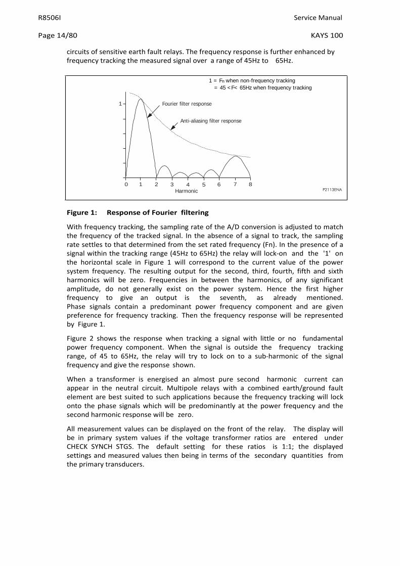
Measurement is based on the Fourier derived value of the power frequency component of current and harmonics up to and including the 6th are suppressed. The 7th harmonic is the first predominant harmonic and this is attenuated by a factor of 3; also higher harmonics are further progressively attenuated by the anti-aliasing filter. This feature eliminates the need for third harmonic rejection filters in the
R8506I Service Manual
Page 14/80 KAYS 100
Fourier filter response
Anti-aliasing filter response
circuits of sensitive earth fault relays. The frequency response is further enhanced by frequency tracking the measured signal over a range of 45Hz to 65Hz.
Figure 1: Response of Fourier filtering
With frequency tracking, the sampling rate of the A/D conversion is adjusted to match the frequency of the tracked signal. In the absence of a signal to track, the sampling rate settles to that determined from the set rated frequency (Fn). In the presence of a signal within the tracking range (45Hz to 65Hz) the relay will lock-on and the '1' on the horizontal scale in Figure 1 will correspond to the current value of the power system frequency. The resulting output for the second, third, fourth, fifth and sixth harmonics will be zero. Frequencies in between the harmonics, of any significant amplitude, do not generally exist on the power system. Hence the first higher frequency to give an output is the seventh, as already mentioned. Phase signals contain a predominant power frequency component and are given preference for frequency tracking. Then the frequency response will be represented by Figure 1.
Figure 2 shows the response when tracking a signal with little or no fundamental power frequency component. When the signal is outside the frequency tracking range, of 45 to 65Hz, the relay will try to lock on to a sub-harmonic of the signal frequency and give the response shown.
When a transformer is energised an almost pure second harmonic current can appear in the neutral circuit. Multipole relays with a combined earth/ground fault element are best suited to such applications because the frequency tracking will lock onto the phase signals which will be predominantly at the power frequency and the second harmonic response will be zero.
All measurement values can be displayed on the front of the relay. The display will be in primary system values if the voltage transformer ratios are entered under CHECK SYNCH STGS. The default setting for these ratios is 1:1; the displayed settings and measured values then being in terms of the secondary quantities from the primary transducers.
1 = Fn when non-frequency tracking = 45 <F< 65Hz when frequency tracking
1
0 1 2 3 4 5 Harmonic
6 7 8 P2113ENA

Service Manual R8506I
KAYS 100 Page 15/80
Figure 2: Frequency response for single voltage input
2.16 Alarms
2.16.1 Scheme alarms
Scheme alarms are indicated by either the red or amber LED being on, steady or flashing, and bit 6 in the SYS Alarms cell is set. See Section 2.11, and below.
2.16.2 Self monitoring alarms
The monitoring circuits within the relay continually perform a self test routine. Any detected loss of operation in the first instance initiates a reset sequence to return the equipment to a serviceable state. Examples of this are the main processor, the communication processor and the display processor. The voltage rails are also supervised and the processors are reset if the voltage falls outside their working range. Should the main processor fail and not restart, the watchdog relay will operate to provide an alarm. This relay will also alarm loss of the auxiliary energising supply to the auxiliary powered relays.
In addition the memory of the relay is checked for possible corruption of data and any detected errors will result in an alarm being generated. An ALARM LED indicates several states which can be identified by viewing the alarm flags that are to be found in the SYSTEM DATA column of the menu and consist of seven characters that may be either "1" or "0" to indicate the set and reset states of the alarm. The flags offer the following indications:
Bit position
7 6 5 4 3 2 1 0
Unconfig - relay not operational - needs to be configured
Uncalib - relay is running uncalibrated - calibration error
Setting - relay is running - possible setting error
No Service - relay is out of service
No Samples - relay not sampling
No Fourier - relay not performing fourier
Scheme Alarm - see the scheme alarms column or default display
Test Watchdog
When any of the above alarms occurs an event is generated at the master station. If more than one alarm occurs at the same time, only the lowest bit position will be sent as the event.
1
0 100 200 Frequency - Hz
300 400 P2114ENa

R8506I Service Manual
Page 16/80 KAYS 100
For the above self monitoring alarms the AMBER ALARM LED will be continuously lit, the alarm bit will be set in the STATUS word as a remote alarm and the watchdog relay will operate. There is another form of alarm that causes the AMBER ALARM LED to flash: this indicates that the password has been entered to allow access to change protected settings within the relay. This does not generate a remote alarm.
The alarm state can be determined via the menu of the relay in the SYS Alarms cell.
Error (0) could result in incorrect operation, due to the configuration error, so the application software is stopped, the watchdog relay given an alarm and the menu locked with the default display showing "Unconfigured".
For error (1) the relay will continue to perform its intended function, but with some reduction in accuracy.
2.16.3 Watchdog test feature
The Test watchdog bit can be set or cleared as a normal setting. When set to 1 the watchdog relay drops off, the amber LED lights up and the alarm bit in the communications status byte is set. When the bit is reset to zero all these features revert to normal.
2.17 Password protection
Password protection is only provided for the configuration settings of the relay. This includes YT ratios, system and check synchronism function link settings, opto- input and relay output allocation. Any accidental change to configuration could seriously affect the ability of the relay to perform its intended functions, whereas, a setting error may only cause a grading problem. Individual relay settings are protected from change when the relay cover is in place.
2.18 Serial communication
Serial communications are supported over K-Bus, a multidrop network that readily interfaces to IEC60870-5 FT1.2 Standards. The language and protocol used for communication is Courier. It has been especially developed to enable Generic Master Station Programs to access many different types of relay without continual modification to the Master Station Program. The relays form a distributed data base for the Master Station and may be polled for any information required. This includes:
1. Measured values
2. Menu text
3. Settings and setting limits
4. Event records
5. Disturbance records
6. Plant status
7. Control status - a 16 bit word wherein the individual bits are assigned in the ladder diagram.
8. Status - an eight bit word that identifies the trip and alarm state, busy state, also the presence of event and disturbance records for collection.
Service Manual R8506I
KAYS 100 Page 17/80
2.18.1 Time tagged event records
An event may be a change of state of an opto input or an output relay or a setting that has been changed locally. A total of 50 events may be stored in a buffer, each with an associated time tag. The time tag is the value of a timer counter that is incremented every 1 millisecond.
The event records can be accessed via the serial communication port when the relay is connected to a suitable master station. When the relay is not connected to a master station the event records can still be extracted within certain limitations:
1. The event records can be read via the serial communication port and a K- Bus/IEC60870-5 interface unit will be required to enable the serial port to be connected to an IBM or compatible PC. Suitable software will be required to run on the PC so that the records can be extracted.
2. When the event buffer becomes full the oldest record is overwritten by the next event.
3. Records are deleted when the auxiliary supply to the relay is removed, to ensure that the buffer does not contain invalid data. Dual powered relays are most likely to be affected.
4. The time tag will be valid for 48 days assuming that the auxiliary supply has not been lost within that time. However, there may be an error of ±4.3 seconds in every 24 hour period due to the accuracy limits of the crystal. This is not a problem when a master station is on line as the relays will usually be polled once every second or so.
Events that are recorded include:
1. Change in state of opto inputs
2. Change in state of relay outputs
3. Change to settings made locally
4. Alarm messages
Items 1 and 2 may be deleted from the events.
2.18.2 Disturbance Records
The internal disturbance recorder has one channel allocated to each of the measured analogue quantities; one to record the eight control inputs; one to record the eight relay outputs. As with the event recorder, when the buffer is full the oldest record is overwritten and records are deleted if the auxiliary supply to the relay is removed. This ensures that when the buffer is read the contents will all be valid.
The disturbance recorder is stopped and the record frozen a set time after a selected trigger has been activated. For example a protection trip command could be the selected trigger and the delay would then set the duration of the trace after the fault.
Each sample has a time tag attached to it so that when the wave form is reconstituted it can be plotted at the correct point against the time scale, thus ensuring that the time base is correct and independent of the frequency. The K-Series relays measure eight samples per cycle but the method of recording allows the analysis program to perform with records that may have a different sample rate.
The disturbance recorders can only be accssed via the serial communications ports.
R8506I Service Manual
Page 18/80 KAYS 100
2.18.3 Remote control functions
Control functions that affect the relay and that can be performed over the serial link include the change of individual relay settings and functions in the scheme logic that are defined in the ladder diagram.
2.18.4 Notes on serial port
Each relay in the K-Series has a serial communication port configured to K-Bus Standards.
K-Bus is a communication interface and protocol designed to meet the requirements of communication with protective relays and transducers within the power system substation environment. It has to be as reliable as the protective relays themselves and must not result in their performance being degraded in any way. Hence error checking and noise rejection has been a major concern in its design.
The communication port is based on RS485 voltage transmission and reception levels with galvanic isolation provided by a transformer. A polled protocol is used and no relay unit is allowed to transmit unless it receives a valid message, without any detected error, addressed to it. Transmission is synchronous, over a pair of screened wires, and the data is FM0 coded with the clock signal to remove any dc component to enable the signal to pass through the transformers. This method of encoding the data results in the polarity of the connection to the bus wiring being unimportant.
With the exception of the master units, each node in the network is passive and any failed unit on the system will not interfere with communication to the other units. The frame format is HDLC and the data rate is 64 kbits/second. Up to 32 units may be connected to any bus at any point over a maximum length of 1000 metres.
2.18.5 Notes on security of remote control via the serial port
Access to the memory of the relay is restricted to that addressed via the menu system of the relay. In addition all setting changes are reflexed back to the master station for verification before the EXECUTE command is issued. On reception of the execute command the new setting is checked against the limits stored in the relay before they are entered. Only then does the relay respond to the new setting.
All remote commands are reflexed back to the master station for verification before they are executed and any command left set is automatically rejected if not executed within the time-out period. No replies are permitted for global commands, as this would cause contention on the bus, instead a double send is used for verification purposes with this type of command.
Remote control is restricted to those functions that have been selected in the relay's menu table and the selection can not be changed without entering the password. CRC and message length checks are used on each message received. No response is given for received messages with a detected error. The master station can be set to retransmit a command a set number of times if it does not receive a reply or receives a reply with a detected error.

Service Manual R8506I
KAYS 100 Page 19/80
3. EXTERNAL CONNECTIONS
Standard connection table
Function Terminal Function
Earth Terminal - 1 2 - Not Used
Watchdog Relay (Break contact)
b -
3 5
4 6
m -
Watchdog Relay (Make contact)
48Y Field Yoltage [+] 7 8 [-] 48Y Field Yoltage
Not Used 9 10 Not Used
Not Used 11 12 Not Used
Auxiliary Yoltage Input (+) 13 14 (-) Auxiliary Yoltage Input
Not Used 15 16 Not Used
Line Yoltage In 17 18 Out Line Yoltage
Busbar Yoltage In 19 20 Out Busbar Yoltage
Not Used 21 22 Not Used
Not Used 23 24 Not Used
Not Used 25 26 Not Used
Not Used 27 28 Not Used
Output Relay 4 - 29 31
30 32
- Output Relay 0
Output Relay 5 - 33 35
34 36
- Output Relay 1
Output Relay 6 - 37 39
38 40
- Output Relay 2
Output Relay 7 - 41 43
42 44
- Output Relay 3
Opto Control Input L3 (+) 45 46 (+) Opto Control Input L0
Opto Control Input L4 (+) 47 48 (+) Opto Control Input L1
Opto Control Input L5 (+) 49 50 (+) Opto Control Input L2
Opto Control Input L6 (+) 51 52 (-) Common L0/L1/L2
Opto Control Input L7 (+) 53 54 - K-Bus Serial Port
Common L3/L4/L5/L6/L7 (-) 55 56 - K-Bus Serial Port
Key to connection tables
[+]and [-] indicate the polarity of the dc output from these terminals (+) and (-) indicate the polarity of the applied dc supply In / Out the signal direction for the in phase condition
Note: All relays have standard Midos terminal blocks to which connections can be made with either 4mm or 4.8mm pre- insulated snap-on connectors. Two connections can be made to each teminal.
R8506I Service Manual
Page 20/80 KAYS 100
3.1 Auxiliary supply
The auxiliary voltage may be ac or dc provided it is within the limiting voltages for the particular relay. The voltage range will be found on the front plate of the relay; it is marked (Yx = 24 - 125Y) or (48 - 250Y). An ideal supply to use for testing the relays will be 50Y dc or 110Y ac because these values fall within both of the auxiliary voltage ranges.
The supply should be connected to terminals 13 and 14 only. To avoid any confusion it is recommended that the polarity of any applied voltage is kept to the Midos standard:
For dc supplies the positive lead connected to terminal 13 and the negative to terminal 14.
For ac supplies the live lead is connected to terminal 13 and the neutral lead to terminal 14.
Note: To avoid damage to the relay do not connect any auxiliary supplies to terminals 7 and 8.
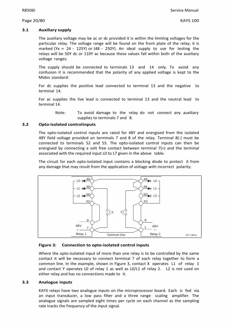
3.2 Opto-isolated control inputs
The opto-isolated control inputs are rated for 48Y and energised from the isolated 48Y field voltage provided on terminals 7 and 8 of the relay. Terminal 8(-) must be connected to terminals 52 and 55. The opto-isolated control inputs can then be energised by connecting a volt free contact between terminal 7(+) and the terminal associated with the required input L0 to L7 given in the above table.
The circuit for each opto-isolated input contains a blocking diode to protect it from any damage that may result from the application of voltage with incorrect polarity.
Figure 3: Connection to opto-isolated control inputs
Where the opto-isolated input of more than one relay is to be controlled by the same contact it will be necessary to connect terminal 7 of each relay together to form a common line. In the example, shown in Figure 3, contact X operates L1 of relay 1 and contact Y operates L0 of relay 1 as well as L0/L1 of relay 2. L2 is not used on either relay and has no connections made to it.
3.3 Analogue inputs
KAYS relays have two analogue inputs on the microprocessor board. Each is fed via an input transducer, a low pass filter and a three range scaling amplifier. The analogue signals are sampled eight times per cycle on each channel as the sampling rate tracks the frequency of the input signal.
X Y
Common line
L0 46 46 L0
L1 48 48 L1
L2 50 52
50 52
L2
8
48V
8
+ Relay 1
7 7 48V +
Relay 2 P2115ENa

Service Manual R8506I
KAYS 100 Page 21/80
P2116ENa
The wide setting range provided is sufficient to enable the relays to operate over the voltage range 5Y to 132Y. Thus the same relay can be connected phase to phase or phase to neutral.
3.4 Output relays
There are four programmable output relays on the microprocessor board and four on the auxiliary expansion board. These relays each have two make contacts connected in series to increase their rating. The functions to which these relays respond are selectable via the menu system of the relay.
In addition there is a watchdog relay which has one make and one break contact. Thus it can indicate both healthy and failed conditions. As these contacts are mainly used for alarm purposes single contacts are used and their rating is therefore not quite as high as that of the programmable outputs.
The terminal numbers for the output relay contacts are given in the table at the start of Section 3.
Figure 4: Terminal arrangement for communications
3.5 Serial communication port (K-Bus)
Connection to the K-Bus Port is by standard Midos 4mm screw terminals or snap-on connectors. A twisted pair of wires is all that is required; the polarity of connection is not important. It is recommended that an outer screen is used with an earth connected to the screen at the Master Station end only. Termination of the screen is effected with the "U" shaped terminal supplied and which has to be secured with a self tapping screw in the hole in the terminal block just below terminal 56. Operation has been tested up to 1,000 metres with cable to:
− DEF Standard 16-2-2c
− 16/0.2mm dia
− 40mΩ/m per core
− 171pf/m core/core
− 288pf/m core/screen
The minimum requirement to communicate with the relay is a K-Bus/IEC60870-5 converter box Type KITZ101 and suitable software to run on an IBM or compatible personal computer.
56
54

R8506I Service Manual
Page 22/80 KAYS 100
Relay types Model number
Liquid crystal display
Made in UK Serial number
F E D C B A 9 8 7 6 5 4 3 2 1 0 LED indicators
Digit identifiers
Entry keys
F + - 0
Ratings
P2117ENa
4. USER INTERFACE
The interface provides the user with a means of entering settings to the relay and of interrogating the relays to retrieve recorded data.
4.1 Front plate layout
KAVS100001012AE No P967701
n Vn
1 A V V
110/12 V Hz 11 50/60
Figure 5: Front plate layout
The front plate of the relay carries an identification label at the top corner. This identifies the relay by both its model number and serial number. This information is required when making any enquiry to the factory about a particular relay because it uniquely specifies the product. In addition there is a rating label in the bottom corner which gives details of the auxiliary voltage rating.
Two handles, one at the top and one at the bottom of the front plate, will assist in removing the module from the case. Three light emitting diodes (leds) provide status indication and in addition there may be a liquid crystal display and a four key pad for access to settings and other readable data.
4.2 LED indications
The three LED's provide the following functions:
GREEN LED Indicates the relay is powered up and running. In most cases it follows the watchdog relay.
YELLOW LED 1) Indicates alarm conditions that have been detected by the relay during its self checking routine.
2) Flashes when the password is entered (password inhibition temporarily overridden).
3) Indicates alarm condition(s) defined in scheme logic have occurred.
Service Manual R8506I
KAYS 100 Page 23/80
RED LED Indicates alarm condition(s) defined in scheme logic have occurred.
4.3 Keypad
Four keys on the front plate of the relay enable the user to select the data to be displayed and settings to be changed. The keys perform the following functions:-
[F] - FUNCTION SELECT KEY
[+] - INCREMENT YALUE KEY
[-] - DECREMENT YALUE KEY
[0] - RESET/ESCAPE KEY
4.4 Liquid crystal display
The liquid crystal display (LCD) has two lines, each of sixteen characters, that are used to display settings, measured values and records which are extracted from the relays' data bank. A backlight is activated when any of the keys on the front plate of the relay is momentarily pressed. This enables the display to be read in all conditions of ambient lighting.
The numbers printed on the front plate just below the display identify the individual digits that are displayed for some of the settings, i.e. function links, relay masks etc.
R8506I Service Manual
Page 24/80 KAYS 100
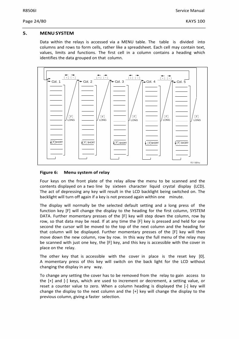
5. MENU SYSTEM
Data within the relays is accessed via a MENU table. The table is divided into columns and rows to form cells, rather like a spreadsheet. Each cell may contain text, values, limits and functions. The first cell in a column contains a heading which identifies the data grouped on that column.
Figure 6: Menu system of relay
Four keys on the front plate of the relay allow the menu to be scanned and the contents displayed on a two line by sixteen character liquid crystal display (LCD). The act of depressing any key will result in the LCD backlight being switched on. The backlight will turn off again if a key is not pressed again within one minute.
The display will normally be the selected default setting and a long press of the function key [F] will change the display to the heading for the first column, SYSTEM DATA. Further momentary presses of the [F] key will step down the column, row by row, so that data may be read. If at any time the [F] key is pressed and held for one second the cursor will be moved to the top of the next column and the heading for that column will be displayed. Further momentary presses of the [F] key will then move down the new column, row by row. In this way the full menu of the relay may be scanned with just one key, the [F] key, and this key is accessible with the cover in place on the relay.
The other key that is accessible with the cover in place is the reset key [0]. A momentary press of this key will switch on the back light for the LCD without changing the display in any way.
To change any setting the cover has to be removed from the relay to gain access to the [+] and [-] keys, which are used to increment or decrement, a setting value, or reset a counter value to zero. When a column heading is displayed the [-] key will change the display to the next column and the [+] key will change the display to the previous column, giving a faster selection.
Col. 1 Col. 2 Col. 3 Col. 4 Col. 5
F LONG
F LONG
F LONG
F LONG
F LONG
F SHORT F SHORT F SHORT F SHORT F SHORT
P2118ENa
Service Manual R8506I
KAYS 100 Page 25/80
When a cell containing a relay setting is displayed the action of pressing either the [+] or [-] keys will indicate to the relay that a value is to be changed and a flashing cursor will appear on the display. To escape from the setting mode, without making any change, the [0] key should be depressed for one second. For instruction on how to change the various types of settings refer to Section 5.2.
5.1 Menu contents
Related data and settings are grouped together in separate columns of the menu. Each column has a text heading that identifies the data contained in that column. Each cell may contain text, values, limits and/or a function. The cells are referenced by the column number/row number. For example 0201 is column 02, row 01.
The full menu is given in the following notes but not all the items will be available in a particular relay. Those cells that do not provide any useful purpose are not made available in the factory configuration to avoid the confusion that would occur in deciding what values to set them to. In a similar way certain settings will disappear from the menu when the user de-selects them.
The menu cells that are read only are marked [READ] .
Cells that can be set are marked [SET].
Cells that can be reset are marked [RESET].
Cells that are password protected are marked [PWP].
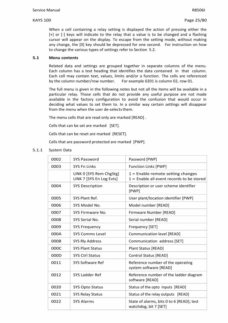
5.1.1 System Data
0002 SYS Password Password [PWP]
0003 SYS Fn Links Function Links [PWP] LINK 0 [SYS Rem ChgStg]
LINK 7 [SYS En Log Evts] 1 = Enable remote setting changes 1 = Enable all event records to be stored
0004 SYS Description Description or user scheme identifier [PWP]
0005 SYS Plant Ref. User plant/location identifier [PWP]
0006 SYS Model No. Model number [READ]
0007 SYS Firmware No. Firmware Number [READ]
0008 SYS Serial No. Serial number [READ]
0009 SYS Frequency Frequency [SET]
000A SYS Comms Level Communication level [READ]
000B SYS Rly Address Communication address [SET]
000C SYS Plant Status Plant Status [READ]
000D SYS Ctrl Status Control Status [READ]
0011 SYS Software Ref Reference number of the operating system software [READ]
0012 SYS Ladder Ref Reference number of the ladder diagram software [READ]
0020 SYS Opto Status Status of the opto inputs [READ]
0021 SYS Relay Status Status of the relay outputs [READ]
0022 SYS Alarms State of alarms, bits 0 to 6 [READ]; test watchdog, bit 7 [SET]

R8506I Service Manual
Page 26/80 KAYS 100
0002 SYS Password [PWP]
The selected configuration of the relay is locked under this password and cannot be changed until it has been entered. Provision has been made for the user to change the password, which may consist of four upper case letters in any combination. In the event of the password becoming lost a recovery password may be obtained on request, but the request must be accompanied by a note of the model and serial number of the relay. The recovery password will be unique to one relay and will not work on any other unless the user set password is the same.
0003 SYS Fn Links [PWP]
These function links enable selection to be made from the system options, for example what commands over the serial link will be acted upon.
LINK 0 [SYS Rem ChgStg] Set to 0, settings can only be changed at the relay. Set to 1, settings can also be changed over the communications link.
LINK 7 [SYS En Log Evts] Set to 0, changes to opto inputs and output relays do not register as events. Set to 1, changes to opto inputs and output relays register as events.
0004 SYS Description [PWP]
This is text that describes the relay type, for example "Auto-reclose". It is password protected and can be changed by the user to a name which may describe the scheme configuration of the relay if the relay is changed from the factory configuration.
0005 SYS Plant Ref. [PWP]
The plant reference can be entered by the user, but it is limited to 16 characters. This reference is used to identify the primary plant that the relay is associated with.
0006 SYS Model No. [READ]
The model number that is entered during manufacture has encoded into it the mechanical assembly, ratings and configuration of the relay. It is the same as the model number printed on the front plate and this number should be quoted in any correspondence concerning the product.
0008 SYS Serial No.[READ]
The serial number is the relay identity and encodes also the year of manufacture. It can not be changed from the menu.
0009 SYS Frequency [SET]
The set frequency from which the relay starts tracking on power-up. It also controls the sampling frequency of the opto inputs, so should be set to the system frequency, even for a KYTR.
000A SYS Comms Level [READ]
This cell will contain the communication level that the relay will support. It is used by Master Station programs to decide what type of commands to send to the relay.
000B SYS Rly Address [SET]
An address between 1 and 254 that identifies the relay when interconnected by a communication bus. These addresses may be shared between several communication buses and therefore not all these addresses will necessarily be
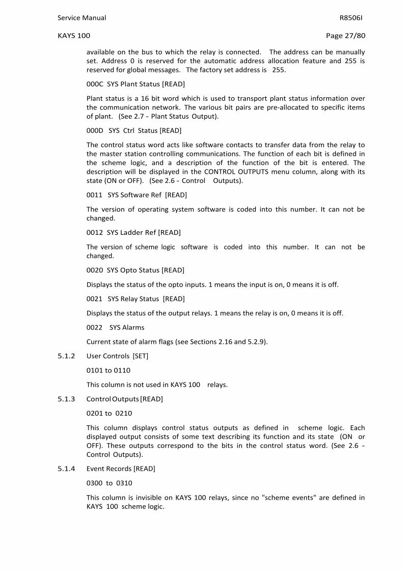
Service Manual R8506I
KAYS 100 Page 27/80
available on the bus to which the relay is connected. The address can be manually set. Address 0 is reserved for the automatic address allocation feature and 255 is reserved for global messages. The factory set address is 255.
000C SYS Plant Status [READ]
Plant status is a 16 bit word which is used to transport plant status information over the communication network. The various bit pairs are pre-allocated to specific items of plant. (See 2.7 - Plant Status Output).
000D SYS Ctrl Status [READ]
The control status word acts like software contacts to transfer data from the relay to the master station controlling communications. The function of each bit is defined in the scheme logic, and a description of the function of the bit is entered. The description will be displayed in the CONTROL OUTPUTS menu column, along with its state (ON or OFF). (See 2.6 - Control Outputs).
0011 SYS Software Ref [READ]
The version of operating system software is coded into this number. It can not be changed.
0012 SYS Ladder Ref [READ]
The version of scheme logic software is coded into this number. It can not be changed.
0020 SYS Opto Status [READ]
Displays the status of the opto inputs. 1 means the input is on, 0 means it is off.
0021 SYS Relay Status [READ]
Displays the status of the output relays. 1 means the relay is on, 0 means it is off.
0022 SYS Alarms
Current state of alarm flags (see Sections 2.16 and 5.2.9).
5.1.2 User Controls [SET]
0101 to 0110
This column is not used in KAYS 100 relays.
5.1.3 Control Outputs [READ]
0201 to 0210
This column displays control status outputs as defined in scheme logic. Each displayed output consists of some text describing its function and its state (ON or OFF). These outputs correspond to the bits in the control status word. (See 2.6 - Control Outputs).
5.1.4 Event Records [READ]
0300 to 0310
This column is invisible on KAYS 100 relays, since no "scheme events" are defined in KAYS 100 scheme logic.

R8506I Service Manual
Page 28/80 KAYS 100
5.1.5 Measurements [READ]
0401 MES Line Yoltage Line voltage
0402 MES Bus Yoltage Bus voltage
0403 MES Phase Angle Angle between the line and bus voltages
0404 MES System Frq Frequency of the line voltage
0405 MES Slip Frq Difference in frequency between the input voltages
This column is only available if one or more check synchronism elements are entered in the ladder diagram.
The measurements display can be selected as the default display.
5.1.6 Counter Yalues [READ]
0500 to 0510
No counter-related functions are used in KAYS 100 scheme logic, so this column is invisible.
5.1.7 Scheme Alarms [READ]
0600 to 0610
This column displays active scheme alarms initiated by scheme logic (See 2.11 - Scheme Alarms).
If no alarms are enabled, cells 0601 to 0610 are invisible. Only those alarms that are turned on will be displayed.
0611 NO ALARMS ENABLED This message is displayed if no alarms are enabled.
0612 RESET ALARMS = [0] Operator-resettable alarms can be reset by pressing the [0] key.
If any alarms are enabled, the alarm text will overwrite the default display.
5.1.8 Check Synch Stgs [SET]
(Check synchronism settings)
0701 CSS Fn. Links Check synchronism function links [PWP]
Link 0 [Synccheck] 1 = enable check synchronism (phase angle check)
Link 1 [Slipfreq] 1 = Enable slip frequency block with ph angle check
Link 2 [Sliptime] 1 = Enable time delay for phase angle check
Link 3 [Splitdet] 1 = Enable system split detector
Link 4 [Splittime] 1 = Enable split timer
Link 5 [Syscheck] 1 = Enable check synchronism (system angle check)
Link 6 [Sysfreq] 1 = Enable slip frequency block with system angle check
Link 7 [Systime] 1 = enable time delay for system angle check
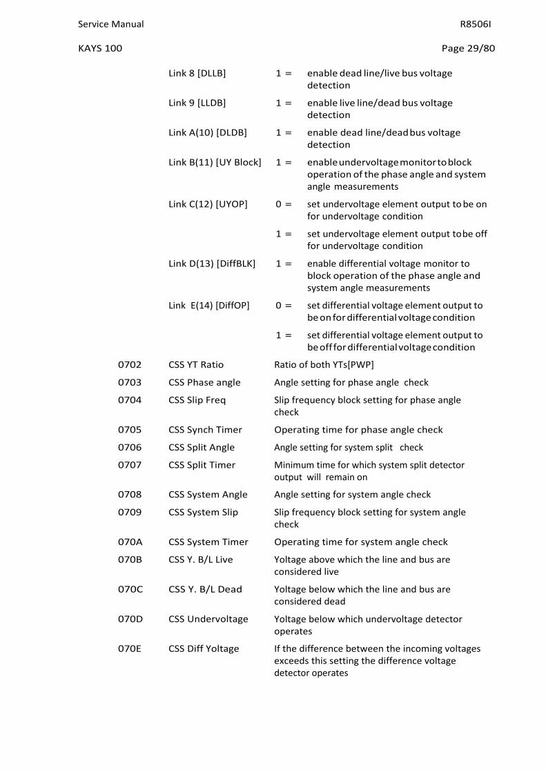
Service Manual R8506I
KAYS 100 Page 29/80
Link 8 [DLLB] 1 = enable dead line/live bus voltage
detection
Link 9 [LLDB] 1 = enable live line/dead bus voltage detection
Link A(10) [DLDB] 1 = enable dead line/dead bus voltage detection
Link B(11) [UY Block] 1 = enable undervoltage monitor to block operation of the phase angle and system angle measurements
Link C(12) [UYOP] 0 = set undervoltage element output to be on for undervoltage condition
1 = set undervoltage element output to be off for undervoltage condition
Link D(13) [DiffBLK] 1 = enable differential voltage monitor to block operation of the phase angle and system angle measurements
Link E(14) [DiffOP] 0 = set differential voltage element output to be on for differential voltage condition
1 = set differential voltage element output to be off for differential voltage condition
0702 CSS YT Ratio Ratio of both YTs[PWP]
0703 CSS Phase angle Angle setting for phase angle check
0704 CSS Slip Freq Slip frequency block setting for phase angle check
0705 CSS Synch Timer Operating time for phase angle check
0706 CSS Split Angle Angle setting for system split check
0707 CSS Split Timer Minimum time for which system split detector output will remain on
0708 CSS System Angle Angle setting for system angle check
0709 CSS System Slip Slip frequency block setting for system angle check
070A CSS System Timer Operating time for system angle check
070B CSS Y. B/L Live Yoltage above which the line and bus are considered live
070C CSS Y. B/L Dead Yoltage below which the line and bus are considered dead
070D CSS Undervoltage Yoltage below which undervoltage detector operates
070E CSS Diff Yoltage If the difference between the incoming voltages exceeds this setting the difference voltage detector operates
R8506I Service Manual
Page 30/80 KAYS 100
5.1.9 Timer Settings [SET]
0801 to 0810
Please refer to Section 2.9 - Time Setting Ranges.
5.1.10 Counter Settings [SET]
0901 to 0910
No counter-related functions are used in KAYS 100 scheme logic, so this column is invisible.
5.1.11 Logic Functions [SET]
0A01 Scheme Fn. Links 1 Function links entered in ladder, numbers 0 to 15 (See 2.8 - Software Logic Functions)
0A02 Scheme Fn. Links 2 Function links entered in ladder, numbers 16 to 31 (See 2.8 - Software Logic Functions)
0A03 LOG Input Status State of inputs to the ladder diagram software (after masking) [READ]
0A04 LOG Output Status State of the outputs of the ladder diagram software, before masking onto the output relays [READ]
0A05 LOG Default Dsply Selects the default display [SET]
The selection can be:
1. The manufacturer's display (K-SERIES MIDOS)
2. The ladder default display
3. Description (or user defined scheme reference)
4. Plant Reference (user defined).
5. Y Line Y Bus
6. The Counter Yalues (not available on KAYS 100)
7. Measurements (see Section 5.1.5)
0A06 LOG Rotation Selects if default display 6 or 7 and the alarm display will change every 5 seconds or only when the [F] key is pressed [SET]
0A07 LOG TEST RELAYS Select Selects output relays which will change state when cell 0A08 is reset [PWP]
0A08 LOG TEST RELAYS = (0) Selected relays will change state when [0] key is pressed [PWP]
5.1.12 Input Masks [PWP]
0B01 to 0B10
An eight bit mask is allocated to each functional logic input in the scheme logic. Please refer to Section 2.3 - Opto isolated inputs. Each cell in the INPUT MASKS column displays on the top line the defined display name for the associated input function, and on the bottom line a series of "1"s and "0"s for the selected mask. The numbers printed on the front plate under the display indicate which opto input (L7 to L0) is associated with each bit. A "1" indicates that the particular opto input will activate the selected logic input, and a "0" indicates that it will not.
Service Manual R8506I
KAYS 100 Page 31/80
5.1.13 Relay Masks [PWP]
0C01 to 0C10
An eight bit mask is allocated to each functional logic output in the scheme logic. Please refer to Section 2.5 - Output relays. Each cell in the RELAY MASKS column displays on the top line the defined display name for the associated output function, and on the bottom line a series of "1"s and "0"s for the selected mask. The numbers printed on the front plate under the display indicate which output relay (RL7 to RL0) is associated with each bit. "1" indicates that the particular output relay will operate when the selected logic output operates, and a "0" indicates that it will not.
5.1.14 Counter Resets [SET]
0D01 to 0D10
No counter-related functions are used in KAYS 100 scheme logic, so this column is invisible.
5.1.15 Recorder (see also Section 5.3)
0E01
0E02
REC control
REC Capture
RUNNING/TRIGGERED/STOPPED [SET]
SAMPLES/MAGNITUDE/PHASE [SET]
0E03 REC Post Trigger Trace length after trigger [SET]
0E04 REC Trig ON Select ladder recorder trigger to trigger when turned on [SET]
0E05 REC Trig OFF Select ladder recorder trigger to trigger when turned off [SET]
5.2 Changing text and settings
To enter the setting mode
Settings and text in certain cells of the menu can be changed via the user interface. To do this the cover must be removed from the front of the relay to gain access to the [+] & [–] keys. Give the [F] key a long press to change from the selected default display and switch on the backlight; the heading SYSTEM DATA will be displayed. Use the [+] & [–] keys, or a long [F] key press, to select the column containing the setting or text cell that is to be changed. Then with the [F] key step down the column until the contents of the cell are displayed. Press the [+] or [–] key to put the relay into the setting mode, which will be indicated by a flashing cursor on the bottom line of the display. If the cell is a read-only cell then the cursor will not appear and the relay will not be in the setting mode.
To escape from the setting mode
To escape from the setting procedure without effecting any change, hold the [0] key depressed for one second. The original setting will be retained
To accept the new setting
Press the [F] key until the display reads:
Are You Sure?
+ = YES - = NO .
Press the [0] key if you decide not to make any change.
Press the [–] key if you want to further modify the data before entry.
R8506I Service Manual
Page 32/80 KAYS 100
Press the [+] to accept the change. This will terminate the setting mode.
5.2.1 Entering passwords (SYS Password cell)
The [+] & [–] keys can be used to select a character at the position of the cursor. When the desired character has been set the [F] key can be given a momentary press to move the cursor to the position for the next character. The process can then be repeated to enter all four characters that make up the password. When the fourth character is acknowledged by a momentary press of the [F] key the display will read:
Are You Sure?
+ = YES - = NO
Press the [0] key if you decide not to enter the password.
Press the [–] key if you want to modify the entry.
Press the [+] to enter the password. The display will then show four stars **** and if the password was accepted the yellow LED will flash. If the password is not accepted a further attempt can be made to enter it, or the [0] key used to escape. Password protection is reinstated when the alarm LED stops flashing, two minutes after the last key press, or by selecting the SYS Password cell, or any menu coloum heading cell, and pressing the [0] key for more than one second.
5.2.2 Changing passwords
After entering the current password and it is accepted, as indicated by the alarm LED flashing, the [F] key is pressed momentarily to move to the next menu cell. If instead, it is required to enter a new password, the [+] key must be pressed to select the setting mode. A new password can be entered with the same procedure described in Section 5.2.1. Only capital (upper case) letters may be used for the password.
Be sure to make a note of the password before entering it.
Access will be denied without the correct password.
5.2.3 Entering text
Enter the setting mode as described in Section 5.2 and move the cursor with the [F] key to where the text is to be entered or changed. Then using the [+] & [–] key select the character to be displayed. The [F] key may then be used to move the cursor to the position of the next character and so on. Follow the instructions in Section 5.2 to exit from the setting change.
5.2.4 Changing function links
Select the page heading required and step down to the FUNCTION LINKS cell required and press either the [+] or [–] to put the relay in a setting change mode. A cursor will flash on the bottom line at the extreme left position. This is link "F"; as indicated by the character printed on the front plate under the display.
Press the [F] key to step along the row of links, one link at a time, until some text appears on the top line that describes the function of a link. The [+] key will change the link to a "1" to set the function and the [–] key will change it to a "0" to clear it. Not all links can be set, some being factory selected and locked. The links that are locked in this way are usually those for functions that are not supported by a particular relay, when they will be set to "0". Merely moving the cursor past a link position does not change it in any way.

Service Manual R8506I
KAYS 100 Page 33/80
5.2.5 Changing setting values
Move through the menu until the cell that is to be edited is displayed. Press the [+] or [–] key to put the relay into the setting change mode. A cursor will flash in the extreme left hand position on the bottom line of the display to indicate that the relay is ready to have the setting changed. The value will be incremented in single steps by each momentary press of the [+] key, or if the [+] key is held down the value will be incremented with increasing rapidity until the key is released. Similarly, the [–] key can be used to decrement the value. Follow the instructions in Section 5.2 to exit from the setting change.
Note: When entering the YT ratio the overall ratio should be entered, i.e. 11000/110Y YT has an overall ratio of 100:1. With rated voltage applied the relay will display 110Y when YT ratio has the default value of 1:1 and when the YT ratio is set to 100:1 the displayed value will be 100 x 110 = 11000Y.
5.2.6 Setting communication address
The communication address will normally be set to 255, the global address to all relays on the network, when the relay is first supplied. Reply messages are not issued from any relay for a global command, because they would all respond at the same time and result in contention on the bus. Setting the address to 255 will ensure that when first connected to the network they will not interfere with communications on existing installations. The communication address can be manually set by selecting the appropriate cell for the SYSTEM DATA column, entering the setting mode as described in Section 5.2 and then decrementing or incrementing the address.
It is recommended that the user enters the plant reference in the appropriate cell and then sets the address manually to "0". The master station will then detect that a new relay has been added to the network and automatically allocate the next available address on the bus to which that relay is connected and communications will then be fully established.
5.2.7 Setting input masks and relay masks
To change a mask setting, it is necessary first to select the SYS Password cell and enter the correct password, as described in Section 5.2.1, then move to the required mask cell, and press either [+] or [–] to put the relay into a setting change mode. A cursor will then flash on the bottom line at bit position 7.
Press the [F] key to step along the row of bits, one at a time, changing bits as required. For each bit to be changed, press [+] to change it to "1" or [–] to change it to "0". Follow the instructions in Section 5.2 to exit from the setting change.
5.2.8 Resetting counter registers
Move to the required cell in the RESET COUNTERS column. The display shows on the top line the counter register display name, and on the bottom line the current contents of that register. Press either [+] or [–] to put the relay into a setting change mode. A cursor will then flash on the bottom line at bit position F.
Press [+]. The word RESET will appear on the bottom line, to the right of the current counter contents. Follow the instructions in Section 5.2 to exit from the reset procedure. If you confirm the reset by pressing [+] when the display shows [Are You Sure? / + = YES - = NO], the display bottom line will change to 0.
R8506I Service Manual
Page 34/80 KAYS 100
5.2.9 Alarm records
The alarm flags are towards the end of the SYSTEM DATA column of the menu and consist of seven characters that may be either "1" or "0" to indicate the set and reset states of the alarm. The control keys perform for this menu cell in the same way as they do for Function Links and, if this cell is selected with the function key [F], the relay can then put in the setting mode by pressing the [+] key. The [F] can then be used to step the cursor to each bit in the alarm status word and text describing the alarm state indicated by the bit selected with the cursor will be displayed as the cursor passes over the individual bits. The numbers printed on the front plate of the relay under the display identify the individual bits in the alarm record. For further details, see 2.16 - Alarms.
No control will be possible via the key pad if the "Unconfigured" alarm is raised because the relay will be locked in a non operate-state.
5.2.10 Default display (LCD)
The LCD changes to a default display if no key presses are made for 15 minutes. The default display can be selected to any of the options listed in Section 5.1.11 LOGIC FUNCTIONS location 0A05 by following the setting procedure given in Section 5.2.5. The display can be returned to the default value, without waiting the 15 minute delay, by selecting any column heading and then holding the [0] reset key depressed for 1 second.
When a scheme alarm occurs, the display changes automatically to display the alarm text. All alarms must be cleared and, if necessary, the Reset Alarms cell reset, as described in Section 2.11, before the relay returns to the selected default display.
5.3 Disturbance recorders
The disturbance recorder may be triggered by several different methods dependent on the settings in this column of the menu. However, the records have to be read via the serial communication port and suitable additional software is required to reconstruct and display the wave forms. Only one complete record is stored and the recorder must be retriggered before another record can be captured.
5.3.1 Recorder control
This cell displays the state of the recorder:
RUNNING - recorder storing data (overwriting oldest data)
TRIGGERED - recorder stop delay triggered
STOPPED - recorder stopped and record ready for retrieval
When this cell is selected, manual control is possible and to achieve this the relay must be put into the setting mode by pressing the [+] key. A flashing cursor will then appear on the bottom line of the display at the left hand side. The [+] key will then select "RUNNING" and the [–] key will select triggered. When the appropriate function has been selected the [F] key is pressed to accept the selection and the selected function will take effect when the [+] key is pressed to confirm the selection. To abort the selection at any stage press the reset key [0].
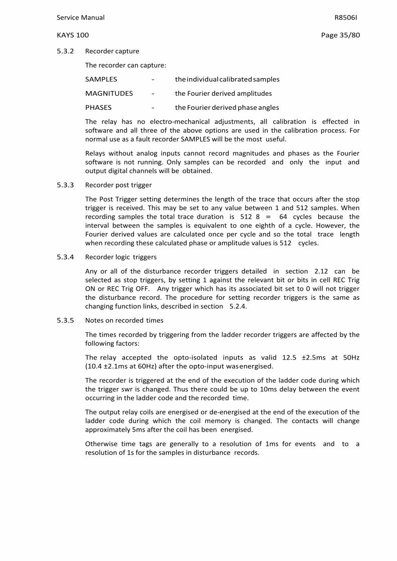
Service Manual R8506I
KAYS 100 Page 35/80
5.3.2 Recorder capture
The recorder can capture:
SAMPLES - the individual calibrated samples
MAGNITUDES - the Fourier derived amplitudes
PHASES - the Fourier derived phase angles
The relay has no electro-mechanical adjustments, all calibration is effected in software and all three of the above options are used in the calibration process. For normal use as a fault recorder SAMPLES will be the most useful.
Relays without analog inputs cannot record magnitudes and phases as the Fourier software is not running. Only samples can be recorded and only the input and output digital channels will be obtained.
5.3.3 Recorder post trigger
The Post Trigger setting determines the length of the trace that occurs after the stop trigger is received. This may be set to any value between 1 and 512 samples. When recording samples the total trace duration is 512 8 = 64 cycles because the interval between the samples is equivalent to one eighth of a cycle. However, the Fourier derived values are calculated once per cycle and so the total trace length when recording these calculated phase or amplitude values is 512 cycles.
5.3.4 Recorder logic triggers
Any or all of the disturbance recorder triggers detailed in section 2.12 can be selected as stop triggers, by setting 1 against the relevant bit or bits in cell REC Trig ON or REC Trig OFF. Any trigger which has its associated bit set to 0 will not trigger the disturbance record. The procedure for setting recorder triggers is the same as changing function links, described in section 5.2.4.
5.3.5 Notes on recorded times
The times recorded by triggering from the ladder recorder triggers are affected by the following factors:
The relay accepted the opto-isolated inputs as valid 12.5 ±2.5ms at 50Hz (10.4 ±2.1ms at 60Hz) after the opto-input was energised.
The recorder is triggered at the end of the execution of the ladder code during which the trigger swr is changed. Thus there could be up to 10ms delay between the event occurring in the ladder code and the recorded time.
The output relay coils are energised or de-energised at the end of the execution of the ladder code during which the coil memory is changed. The contacts will change approximately 5ms after the coil has been energised.
Otherwise time tags are generally to a resolution of 1ms for events and to a resolution of 1s for the samples in disturbance records.

R8506I Service Manual
Page 36/80 KAYS 100
6. SCHEME LOGIC
KAYS 100 relays scheme logic is documented in drawing number 08 KAYS 100 01, sheets 1 to 6. Sheet 1 lists all the scheme logic elements accessible via the user interface, sheets 2 to 5 document the logic in ladder diagram format, and sheet 6 lists the factory default relay settings.
6.1 Ladder logic: general description
The ladder logic shown in the above drawing is a graphical representation of the actual scheme logic. The ladder logic is arranged in a series of pages, each having six rows of seven elements. Each element position can be either blank or occupied by a graphical symbol representing a specific logic test (in columns 1 to 6 from the left hand side of the page) or logic flag (in column 7). A key to the ladder logic symbols is given in drawing number 08 KAXX 00 sheets 1 & 2.
The scheme logic is executed once every ten milliseconds, executing all pages sequentially, starting with page 1. On every page, the logic tests are executed column by column from left to right across the page, then the flags or actions in column 7 are set or reset according to the inputs resulting from the logic tests, before the next page logic is tested. The flags on each page then remain in the same state until that page is tested again during the next logic execution. It is important to remember that during the logic tests on any page, the status of any flag on that page is seen as it was at the end of the previous execution: the new flag state resulting from the current logic execution is not seen in logic tests on that page until the next execution.
It may be easier to interpret the scheme logic if the ladder logic is read as an electromagnetic schematic diagram, treating the left and right side uprights as positive and negative supply rails, flags in column 7 as relay coils, and logic test symbols in columns 1 to 6 as "make" or "break" relay contacts, time delayed contacts, etc. Using this approach, it is important to remember (i) the sequential page by page execution as described above, and (ii) all horizontal elements "conduct" left to right only, as if each incorporates a blocking diode.
6.2 Ladder logic: element identification
6.2.1 Inputs
Each ladder logic "contact" associated with a scheme logic input mask or user input is identified by a short ladder name, which is an abbreviated version of its full display name. Each element is further identified "input n" or "userin n", where "n" refers to the position of the input in the associated list in section 2.3 or 2.4. List numbering starts at 0. "Input n" numbers refer to the list positions of INPUT MASKS, not to any specific opto-inputs.
6.2.2 Outputs and software relays
Each ladder scheme logic output or control output element has a short ladder name, which is an abbreviated version of its full display name. Each "coil" symbol in column 7 is further identified "RL n" or "CS n", where "n" refers to the position of the output in the associated list in section 2.5 or 2.6. List numbering starts at 0. "RL n" numbers refer to the list positions of output RELAY MASKS, not to any specific output relay contacts.
Each internal scheme logic flag, or "software relay", has a short ladder name, but no other identification.
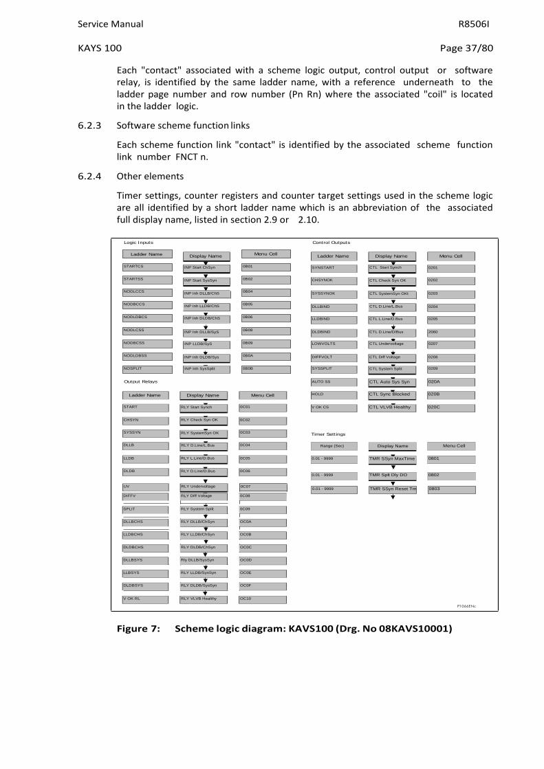
Service Manual R8506I
KAYS 100 Page 37/80
0C07 TMR SSyn Reset Tm 0.01 - 9999 0803
Logic Inputs Control Outputs
Output Relays
Timer Settings
P1066ENc
Ladder Name Menu Cell
STARTCS 0B01
STARTSS 0B02
NODLCCS 0B04
NODBCCS 0B05
NODLDBCS 0B06
NODLCSS 0B08
NODBCSS 0B09
NODLDBSS 0B0A
NOSPLIT 0B0B
Each "contact" associated with a scheme logic output, control output or software relay, is identified by the same ladder name, with a reference underneath to the ladder page number and row number (Pn Rn) where the associated "coil" is located in the ladder logic.
6.2.3 Software scheme function links
Each scheme function link "contact" is identified by the associated scheme function link number FNCT n.
6.2.4 Other elements
Timer settings, counter registers and counter target settings used in the scheme logic are all identified by a short ladder name which is an abbreviation of the associated full display name, listed in section 2.9 or 2.10.
Figure 7: Scheme logic diagram: KAVS100 (Drg. No 08KAVS10001)
0C06
RLY D.Line/D.Bus
DLDB
0801
TMR SSyn MaxTime
0.01 - 9999
0C05
RLY L.Line/D.Bus
LLDB
Menu Cell
Display Name
Range (Sec)
0C04
RLY D.Line/L.Bus
DLLB
0C03
RLY SystemSyn OK
SYSSYN
0C02
RLY Check Syn OK
CHSYN
020C
CTL VLVB Healthy
V OK CS
0C01
RLY Start Synch
START
020B
CTL Sync Blocked
HOLD
Menu Cell
Display Name
Ladder Name
020A
CTL Auto Sys Syn
AUTO SS
0209
CTL System Split
SYSSPLIT
INP Inh SysSplit
0207
CTL Undervoltage
LOWVOLTS
INP LLDB/SyS
0205
CTL L.Line/D.Bus
LLDBIND
INP Inh DLDB/ChS
0203
CTL SystemSyn OKt
CTL D.Line/L.Bus
SYSSYNOK
INP Inh DLLB/ChS
INP Inh LLDB/ChS
0202
CTL Check Syn OK
CHSYNOK
INP Start SysSyn
0201
CTL Start Synch
SYNSTART
INP Start ChSyn
Display Name
Ladder Name
Display Name
Menu Cell
INP Inh DLLB/SyS
DLDBIND
CTL D.Line/D/Bus
2060
INP Inh DLDB/Sys
DIFFVOLT
CTL Diff Voltage
0208
DLLBIND
0204
0.01 - 9999
TMR Splt Dly DO
0802
UV
RLY Undervoltage
DIFFV RLY Diff Voltage 0C08
SPLIT RLY System Split 0C09
DLLBCHS RLY DLLB/ChSyn OC0A
LLDBCHS RLY LLDB/ChSyn OC0B
DLDBCHS RLY DLDB/ChSyn OC0C
DLLBSYS Rly DLLB/SysSyn OC0D
LLBSYS RLY LLDB/SysSyn OC0E
DLDBSYS RLY DLDB/SysSyn OC0F
V OK RL RLY VLVB Healthy OC10

R8506I Service Manual
Page 38/80 KAYS 100
P1068ENb
Figure 8: Scheme logic diagram: KAVS100 (Drg. No 08 KAVS10001)

Service Manual R8506I
KAYS 100 Page 39/80
P1069ENb
Figure 9: Scheme logic diagram: KAVS100 (Drg. No 08KAVS10001)

R8506I Service Manual
Page 40/80 KAYS 100
P1070ENb
Figure 10: Scheme logic diagram: KAVS100 (Drg. No 08KAVS10001)

Service Manual R8506I
KAYS 100 Page 41/80
P1071ENc
Figure 11: Scheme logic diagram: KAVS100 008 (Drg. No 08KAVS10001)

R8506I Service Manual
Page 42/80 KAYS 100
P1120ENb
Figure 12: Relay settings: Type KAVS100 (Standard factory settings)
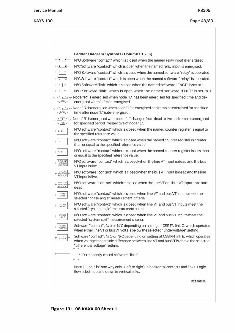
Service Manual R8506I
KAYS 100 Page 43/80
T
DPU
T
DDU
T
PLS
Ladder Diagram Symbols (Columns 1 - 6)
N/O Software "contact" which is closed when the named relay input is energised.
N/C Software "contact" which is open when the named relay input is energised.
N/O Software "contact" which is closed when the named software "relay" is operated.
N/C Software "contact" which is open when the named software "relay" is operated.
N/O Software "link" which is closed when the named software "FNCT" is set to 1.
N/C Software "link" which is open when the named software "FNCT" is set to 1.
"L "R" Node "R" is energised when node "L" has been energised for specified time and de- energised when "L" is de-energised.
"L "R" Node "R" is energised when node "L" is energised and remains energised for specified time after node "L" is de-energised.
"L "R" Node "R" is energised when node "L" changes from dead to live and remains energised for specified period irrespective of node "L".
N/O software "contact" which is closed when the named counter register is equal to the specified reference value.
N/O software "contact" which is closed when the named counter register is greater than or equal to the specified reference value.
N/O software "contact" which is closed when the named counter register is less than or equal to the specified reference value.
N/O software "contact" which is closed when the line VT input is dead and the bus VT input is live.
N/O software "contact" which is closed when the bus VT input is dead and the line VT input is live.
N/O software "contact" which is closed when the line VT and bus VT inputs are both dead.
N/O software "contact" which is closed when line VT and bus VT inputs meet the selected "phase angle" measurement criteria.
N/O software "contact" which is closed when line VT and bus VT inputs meet the selected "system angle" measurement criteria.
N/O software "contact" which is closed when line VT and bus VT inputs meet the selected "system split" measurement criteria.
Software "contact", N/o or N/C depending on setting of CSS FN link C, which operates when either line VT or bus VT volts is below the selected "undervoltage" setting.
Software "contact", N/O or N/C depending on setting of CSS FN link E, which operates when voltage magnitude difference between line VT and bus VT is above the selected "differential voltage" setting.
Permanently closed software "links"
Note 1. Logic is "one way only" (left to right) in horizontal contacts and links. Logic flow is both up and down in vertical links.
P2126ENA
Figure 13: 08 KAXX 00 Sheet 1
< =
DEADL NE L VE BUS MON TOR
L VEL NE DEAD BUS MON TOR
DEADL NE DEAD BUS MON TOR
= =
> =
PHASE ANGLE
SYSTEM ANGLE
SYSTEM SPL T
UNDER VOLTAGE
D FF VOLTAGE

R8506I Service Manual
Page 44/80 KAYS 100
Figure 14: 08 KAXX 00 Sheet 2
Ladder Diagram Symbols (Column 7) Software "relay": Operates when node "L" is energised. "L"
"L" M
"L" B
"L"
"L" "L" NC+
"L" NC-
"L" RES+
"L" RES-
"L" DEC+
"L" DEC-
Software "Relay" with power off memory: Recalls its previous status when dc auxiliary supply is restored after interruption.
Software "relay" blocks access to the named function of the user interface when live. Software "relay" with LED indicator.
Software "relay" with output element having contacts wired to relay terminals (relay number RL - given in brackets. Output contacts shown on extrtnal connections diagram).
Named counter register increments by 1 when node "L" changes from dead to live.
Named counter register increments by 1 when node "L" changes from live to dead.
Named counter register resets to zero when node "L" changes from dead to live.
Named counter register resets to zero when node "L" changes from live to dead.
Named counter register decrements by 1 when node "L" changes from dead to live.
Named counter register decrements by 1 when node "L" changes from live to dead.
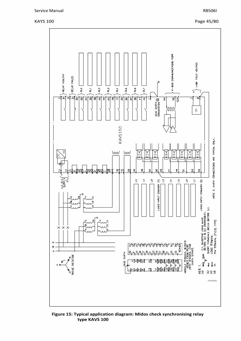
Service Manual R8506I
KAYS 100 Page 45/80
Figure 15: Typical application diagram: Midos check synchronising relay type KAVS 100
P1067ENa

R8506I Service Manual
Page 46/80 KAVS 100
7. TECHNICAL DATA
7.1 Ratings
Inputs
Input voltage (Vn) Nominal rating Continuous rating (KAVR and KAVS only) 63.5/110V 440V
Auxiliary voltage (Vx) Nominal rating Operative range Absolute maximum
dc supply ac 50/60Hz Auxiliary powered 24 – 125V ac/dc 19 - 150V 50 – 133V 190V crest
48 – 250V ac/dc 33 – 300V 87 – 265V 380V crest
Frequency (Fn) Nominal rating Reference range Frequency tracking 50Hz or 60Hz 45 – 65Hz Non tracking Non tracking 47 – 51Hz or 57 – 61Hz
Opto-Isolated Inputs Nominal rating Reference range Supply 50V dc only 25 – 60V dc only
7.1.1 Outputs
Field voltage 48V dv (current limited to 60mA)
7.2 Burdens
7.2.1 Voltage circuits
0.012VA at 110V
0.15VA at 327V
0.87VA at 440V
7.2.2 Auxiliary voltage
DC supply 2.5 – 6.0W at Vx max with no output relays or logic inputs energized
4.0 – 8.0W at Vx max with 2 output relays and 2 logic inputs energized
5.5 – 12W at Vx max with all output relays and logic inputs energized
AC supply 6.0 – 12VA at Vx max with no output relays or logic inputs energized
6.0 – 14VA at Vx max with 2 output relays and 2 logic inputs energized
13 – 23VA at Vx max with all output relays and logic inputs energized
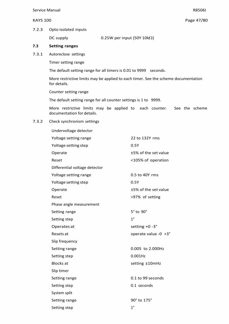
Service Manual R8506I
KAYS 100 Page 47/80
7.2.3 Opto-isolated inputs
DC supply 0.25W per input (50Y 10kΩ)
7.3 Setting ranges
7.3.1 Autoreclose settings
Timer setting range
The default setting range for all timers is 0.01 to 9999 seconds.
More restrictive limits may be applied to each timer. See the scheme documentation for details.
Counter setting range
The default setting range for all counter settings is 1 to 9999.
More restrictive limits may be applied to each counter. See the scheme documentation for details.
7.3.2 Check synchronism settings
Undervoltage detector
Yoltage setting range 22 to 132Y rms
Yoltage setting step 0.5Y
Operate ±5% of the set value
Reset <105% of operation
Differential voltage detector
Yoltage setting range 0.5 to 40Y rms
Yoltage setting step 0.5Y
Operate ±5% of the set value
Reset >97% of setting
Phase angle measurement
Setting range 5° to 90°
Setting step 1°
Operates at setting +0 -3°
Resets at operate value -0 +3°
Slip frequency
Setting range 0.005 to 2.000Hz
Setting step 0.001Hz
Blocks at setting ±10mHz
Slip timer
Setting range 0.1 to 99 seconds
Setting step 0.1 seconds
System split
Setting range 90° to 175°
Setting step 1°

R8506I Service Manual
Page 48/80 KAYS 100
Operates at setting +0 -3°
Resets at operate value -0 +3°
Split timer
Setting range 0.1 to 99 seconds
Setting step 0.1 seconds
System angle measurement
Setting range 5° to 90°
Setting step 1°
Operates at setting +0 -3°
Resets at operate value -0 +3°
System slip frequency
Setting range 0.005 to 2.000Hz
Setting step 0.001Hz
Blocks at setting ±10mHz
System timer
Setting range 0.1 to 99 seconds
Setting step 0.1 seconds
Live voltage
Setting range Dead voltage setting to 132Y
Setting step 0.5Y
Operates at ±5% of setting
Resets at >98% of operate value
Dead voltage
Setting range 5.5Y to live voltage setting
Setting step 0.5Y
Operates at ±5% of setting
Resets at <104% of operate value
Note: The live voltage setting cannot be set to less than the dead voltage setting, and the dead voltage setting cannot be set to greater than the live voltage setting.
7.3.3 Measurement (displayed)
Yoltage Yin x YT ratio for Y Line and Y Bus
Phase angle ±180° Angle between Y Line and Y Bus
System frequency 45 - 65Hz Frequency of Y Line
Slip frequency ±32Hz Difference in frequency between Y Line and Y Bus
7.3.4 Ratios
YT ratios 1:1 to 9999:1 Default = 1:1

Service Manual R8506I
KAYS 100 Page 49/80
7.4 Accuracy
7.4.1 General for reference conditions
Ambient temperature 20°C Frequency 50Hz or 60Hz (whichever set) Auxiliary voltage 24Y to 125Y (aux. powered)
48Y to 250Y (aux. powered) Auto reclose timers
±0.5%
The operating time for scheme logic functions is also affected by :
− The input sampling time (5/8 x system period)
− The number of executions of the ladder code needed to perform the function. An execution occurs every 10ms.
− The time for an output relay to close its contacts (typically 5ms)
Undervoltage detector
Operation ±5% of the set value
Reset <105% of operation
Differential voltage detector
Operation ±5% of the set value
Reset >97% of operation
Phase angle and system angle measurement
Operation setting -3 +0°
Resets operate value -0 +3°
Slip frequency and system slip frequency
Operation setting ±0.010Hz
Reset setting ±0.010Hz
Split angle measurement
Operation setting -3 +0°
Resets operate value -3 +0°
Check synchronism timers
All timers ±0.5% + 0 to 40ms
Live voltage monitor
Operation ±5% of the set value
Reset <98% of operation
Dead voltage monitor
Operation ±5% of the set value
Reset <104% of operation
Measurements
Yoltage ±5% of reading (±1% Yn typical)

R8506I Service Manual
Page 50/80 KAYS 100
Frequency (45 - 65Hz) ±5% of reading (±1% Fn typical)
Phase angle ±0.5° (typical)
7.4.2 Influencing quantities
Ambient temperature Operative range -25°C to +55°C
Yoltage settings 0.03% per °C
Operation times 1%
Angle measurement 2°
Frequency Operative range 46 to 65Hz
Yoltage settings 1%
Operation times 1%
Angle measurement <1°
Auxiliary supply
Yoltage settings 0.5%
Operation times 0.5%
Angle measurement 0.5°
7.5 Opto-isolated control inputs
Capture time 12.5 ±2.5ms at 50Hz
10.4 ±2.1ms at 60Hz
Release time 12.5 ±2.5ms at 50Hz
10.4 ±2.1ms at 60Hz
Maximum series lead resistence 5kΩ (2 optos in parallel)
Maximum ac induced loop voltage >50Y rms (thermal limit)
Maximum capacitance coupled ac voltage >250Y rms via 0.1µF
7.6 Contacts
Output relays 0 to 7
Type 2 make contacts connected in series
Rating
Make and carry continuously 5A
Make and carry for 0.2s 30A
Break ac 1250YA with maxima of 5A and 300Y
dc 50W resistive 25W inductive (L/R = 0.04s) with maxima of 5A and 300Y)
Watchdog 1 make and 1 break
Nominal Operative range
24/125Y 19 to 150Y dc (aux. powered) 50 to 133Y ac (aux. powered)
48/250Y 33 to 300Y dc (aux. powered) 87 to 265Y ac (aux. powered)
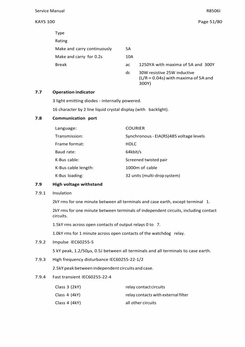
Service Manual R8506I
KAYS 100 Page 51/80
Type
Rating
Make and carry continuously 5A
Make and carry for 0.2s 10A
Break ac 1250YA with maxima of 5A and 300Y
dc 30W resistive 25W inductive (L/R = 0.04s) with maxima of 5A and 300Y)
7.7 Operation indicator
3 light emitting diodes - internally powered.
16 character by 2 line liquid crystal display (with backlight).
7.8 Communication port
Language: COURIER
Transmission: Synchronous - EIA(RS)485 voltage levels
Frame format: HDLC
Baud rate: 64kbit/s
K-Bus cable: Screened twisted pair
K-Bus cable length: 1000m of cable
K-Bus loading: 32 units (multi-drop system)
7.9 High voltage withstand
7.9.1 Insulation
2kY rms for one minute between all terminals and case earth, except terminal 1.
2kY rms for one minute between terminals of independent circuits, including contact circuits.
1.5kY rms across open contacts of output relays 0 to 7.
1.0kY rms for 1 minute across open contacts of the watchdog relay.
7.9.2 Impulse IEC60255-5
5 kY peak, 1.2/50µs, 0.5J between all terminals and all terminals to case earth.
7.9.3 High frequency disturbance IEC60255-22-1/2
2.5kY peak between independent circuits and case.
7.9.4 Fast transient IEC60255-22-4
Class 3 (2kY) relay contact circuits
Class 4 (4kY) relay contacts with external filter
Class 4 (4kY) all other circuits

R8506I Service Manual
Page 52/80 KAYS 100
7.9.5 Static discharge test
Class 4 (15kY) discharge in air with cover in place
Class 3 (6kY) point contact discharge with cover removed 7.9.6 ANSI/IEEE standards C36.90
The relay also complies with the appropriate ANSI-IEEE standards for power-system protection relays
7.10 Environmental
7.10.1 Temperature IEC60068-2-3
Storage and transit -25°C to +70°C
Operating -25°C to +55°C
7.10.2 Humidity IEC60068-2-3
56 days at 93% relative humidity and 40°C
7.10.3 Enclosure protection IEC60529
IP50 (Dust protected)
7.10.4 Yibration IEC255-21-1
0.5g between 60Hz and 600Hz
0.07 mm peak to peak between 10Hz and 60Hz.
7.10.5 Mechanical durability
10,000 operations, minimum.
7.11 Model numbers
Configuration (i.e. settings as supplied) and connection diagram (sheet number varies with external connection arrangements).
KAVS100 CO CS RTG A
ssue Ratings Case details Relay type
Mechanical assembly
P1073ENa
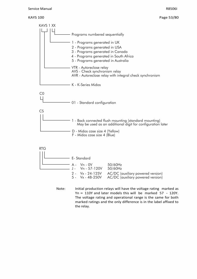
Service Manual R8506I
KAYS 100 Page 53/80
KAVS 1 XX
Programs numbered sequentially
1 - Programs generated in UK 2 - Programs generated in USA 3 - Programs generated in Canada 4 - Programs generated in South Africa 5 - Programs generated in Australia
VTR - Autoreclose relay AVS - Check synchronism relay AVR - Autoreclose relay with integral check synchronism
K - K-Series Midos
C0
CS
RTG
01 - Standard configuration
1 - Back connected flush mounting (standard mounting) May be used as an additional digit for configuration later
D - Midos case size 4 (Yellow) F - Midos case size 4 (Blue)
E- Standard
A - Vn - 0V 50/60Hz J - Vn - 57-120V 50/60Hz 2 - Vx - 24-125V AC/DC (auxiliary powered version) 5 - Vx - 48-250V AC/DC (auxiliary powered version)
Note: Initial production relays will have the voltage rating marked as
Yn = 110Y and later models this will be marked 57 - 120Y. The voltage rating and operational range is the same for both marked ratings and the only difference is in the label affixed to the relay.

R8506I Service Manual
Page 54/80 KAYS 100
8. COMMISSIONING
8.1 Commissioning preliminaries
When commissioning a K-Series relay for the first time the engineers should allow an hour to get familiar with the menu. Please read Section 8.1.1 which provides simple instructions for negotiating the relay menu using push buttons [F] [+] [–] and [0] on the front of the relay. Individual cells can be viewed and the settable values can be changed by this method.
If a portable PC is available together with a K-Bus interface unit and the commissioning software, then the menu can be viewed a page at a time to display a full column of data and text. Settings are also more easily entered and the final settings can be saved to a file on a disk for future reference or printing a permanent record. The instructions are provided with the Courier Access software.
8.1.1 Quick guide to local menu control
With the cover in place only the [F] and [0] push buttons are accessible, so data can only be read or flag and counter functions reset. No settings can be changed. In the table [F] long indicates that the key is pressed for at least 1 second and [F] short for less than 0.5 seconds. This allows the same key to perform more than one function.
8.1.1.1 With the cover fitted to the case
Current display Key press
Effect of action
Default display or Scheme alarm(s)
[F] short Display changes to next item in list, if any available
Display changes to first menu column heading "SYSTEM DATA"
Backlight turns ON
[F] long
[0] short
or [0] long
Column Heading [0] short
[0] long
Backlight turns ON
Returns to the selected default display, or scheme alarms, without waiting for the 2 minute delay
Anywhere in menu [F] short
[F] long
[0] short
[0] long
Displays the next item of data in the column
Displays the heading for the next column
Backlight turns ON
If a resettable cell is displayed it will be reset
Table 8.1

Service Manual R8506I
KAYS 100 Page 55/80
8.1.1.2 With the cover removed from the case
Current display Key press
Effect of action
Column Heading [+] Move to next column heading [–] Move to previous column heading
A settable cell [+] or [–] Puts the relay in the setting mode (flashing cursor on bottom line of display) if the cell is not password protected or blocked in the ladder diagram
Setting mode [+] Increments value [–]
[F] Decrements value
Changes to the confirmation display If function links, relay or input masks are displayed then the [F] key will step through them from left to right. A further key press will change to the confirmation display [0] Escapes from the setting mode without setting
being changed
Confirmation [+] Confirms setting and enters new value display [–] Returns prospective value of setting for
checking and further modification [0] Escapes from the setting mode without the setting being changed
Table 8.2 8.1.2 Terminal allocation
Reference should be made to the diagram supplied with every relay. The diagram number will be found on the label fixed inside the case to the left hand side. Section 3 of the document provides useful notes on the connections to the relay
8.1.3 Electrostatic discharge (ESD)
See recommendations in Section 1 of this service manual before handling the module outside its case
8.1.4 Inspection
Carefully examine the module and case to see that no damage has occurred since installation and visually check the current transformer shorting switches in the case are wired into the correct circuit and are closed when the module is withdrawn. Check the serial number on the module, case and cover are identical and that the model number and rating information is correct.
Check that the external wiring is correct to the relevant relay diagram or scheme diagram. The relay diagram number appears inside the case on a label at the left hand side. The serial number of the relay also appears on this label, the inside of the cover and on the front plate of the relay module. The serial numbers marked on these three items should match; the only time that they may not match is when a failed relay module has been replaced for continuity of protection.
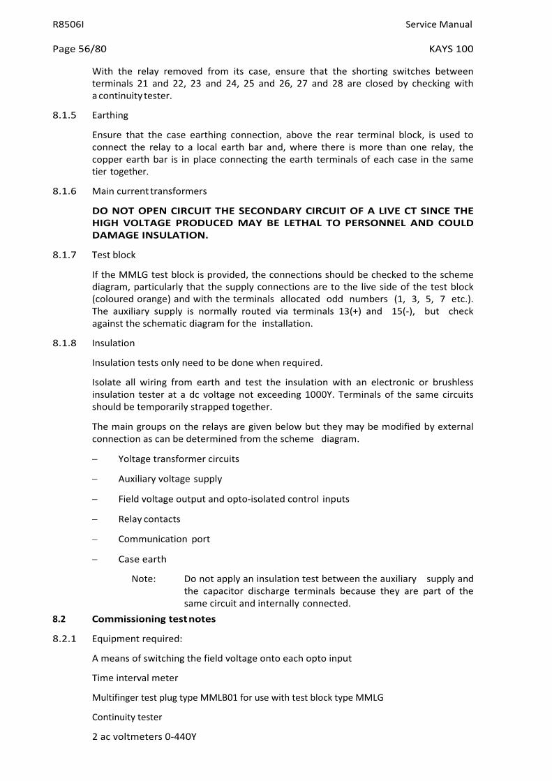
R8506I Service Manual
Page 56/80 KAYS 100
With the relay removed from its case, ensure that the shorting switches between terminals 21 and 22, 23 and 24, 25 and 26, 27 and 28 are closed by checking with a continuity tester.
8.1.5 Earthing
Ensure that the case earthing connection, above the rear terminal block, is used to connect the relay to a local earth bar and, where there is more than one relay, the copper earth bar is in place connecting the earth terminals of each case in the same tier together.
8.1.6 Main current transformers
DO NOT OPEN CIRCUIT THE SECONDARY CIRCUIT OF A LIVE CT SINCE THE HIGH VOLTAGE PRODUCED MAY BE LETHAL TO PERSONNEL AND COULD DAMAGE INSULATION.
8.1.7 Test block
If the MMLG test block is provided, the connections should be checked to the scheme diagram, particularly that the supply connections are to the live side of the test block (coloured orange) and with the terminals allocated odd numbers (1, 3, 5, 7 etc.). The auxiliary supply is normally routed via terminals 13(+) and 15(-), but check against the schematic diagram for the installation.
8.1.8 Insulation
Insulation tests only need to be done when required.
Isolate all wiring from earth and test the insulation with an electronic or brushless insulation tester at a dc voltage not exceeding 1000Y. Terminals of the same circuits should be temporarily strapped together.
The main groups on the relays are given below but they may be modified by external connection as can be determined from the scheme diagram.
− Yoltage transformer circuits
− Auxiliary voltage supply
− Field voltage output and opto-isolated control inputs
− Relay contacts
− Communication port
− Case earth
Note: Do not apply an insulation test between the auxiliary supply and the capacitor discharge terminals because they are part of the same circuit and internally connected.
8.2 Commissioning test notes
8.2.1 Equipment required:
A means of switching the field voltage onto each opto input
Time interval meter
Multifinger test plug type MMLB01 for use with test block type MMLG
Continuity tester
2 ac voltmeters 0-440Y
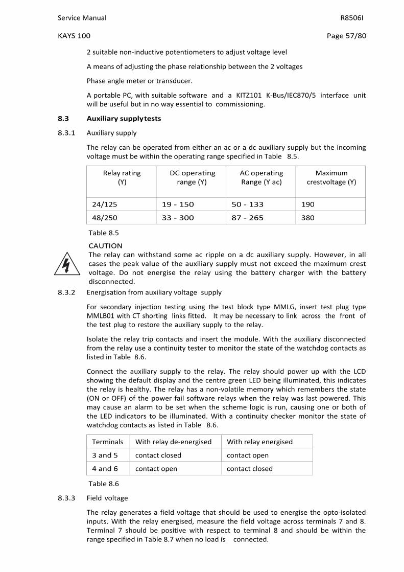
Service Manual R8506I
KAYS 100 Page 57/80
2 suitable non-inductive potentiometers to adjust voltage level
A means of adjusting the phase relationship between the 2 voltages
Phase angle meter or transducer.
A portable PC, with suitable software and a KITZ101 K-Bus/IEC870/5 interface unit will be useful but in no way essential to commissioning.
8.3 Auxiliary supply tests
8.3.1 Auxiliary supply
The relay can be operated from either an ac or a dc auxiliary supply but the incoming voltage must be within the operating range specified in Table 8.5.
Relay rating (Y)
DC operating range (Y)
AC operating Range (Y ac)
Maximum crestvoltage (Y)
24/125 19 - 150 50 - 133 190
48/250 33 - 300 87 - 265 380
Table 8.5
CAUTION The relay can withstand some ac ripple on a dc auxiliary supply. However, in all cases the peak value of the auxiliary supply must not exceed the maximum crest voltage. Do not energise the relay using the battery charger with the battery disconnected.
8.3.2 Energisation from auxiliary voltage supply
For secondary injection testing using the test block type MMLG, insert test plug type MMLB01 with CT shorting links fitted. It may be necessary to link across the front of the test plug to restore the auxiliary supply to the relay.
Isolate the relay trip contacts and insert the module. With the auxiliary disconnected from the relay use a continuity tester to monitor the state of the watchdog contacts as listed in Table 8.6.
Connect the auxiliary supply to the relay. The relay should power up with the LCD showing the default display and the centre green LED being illuminated, this indicates the relay is healthy. The relay has a non-volatile memory which remembers the state (ON or OFF) of the power fail software relays when the relay was last powered. This may cause an alarm to be set when the scheme logic is run, causing one or both of the LED indicators to be illuminated. With a continuity checker monitor the state of watchdog contacts as listed in Table 8.6.
Terminals With relay de-energised With relay energised
3 and 5 contact closed contact open
4 and 6 contact open contact closed
Table 8.6
8.3.3 Field voltage
The relay generates a field voltage that should be used to energise the opto-isolated inputs. With the relay energised, measure the field voltage across terminals 7 and 8. Terminal 7 should be positive with respect to terminal 8 and should be within the range specified in Table 8.7 when no load is connected.

R8506I Service Manual
Page 58/80 KAYS 100
Nominal dc rating (Y)
Range (Y)
48 45 - 60
Table 8.7 8.4 Measurement checks
To test the relay measurement functions a known voltage should be injected into each ac input.
With the CSS YT Ratio setting equal to the actual YT primary/secondary volts ratio, the displayed measured values and settings will be in the equivalent primary quantities. If CSS YT Ratio is set to 1.000 : 1, the displayed values will be the secondary voltages actually applied at the relay terminals.
All measured values have a tolerance of ±5%.
8.5 Opto-input checks
This test is to check that all the opto inputs are functioning correctly. The state of the opto-isolated input can be viewed from the [SYS Opto Status] display under the SYSTEM DATA heading. To enable energisation of the opto-inputs, terminal 8 should be linked to terminals 52 and 55.
If external equipment is connected to any of the opto input terminals, this test can be used to check both the external wiring and correct operation of the external contact when the relevant equipment is operated.
If external equipment is not yet connected to all of the opto input terminals, the unconnected opto inputs may be tested by individually connecting relay terminal 7 to the relevant opto input terminal listed below.
Opto-input number Terminal
L0 46
L1 48
L2 50
L3 45
L4 47
L5 49
L6 51
L7 53
The status of each opto-input can be viewed by displaying [SYS Opto Status] which will be found towards the end of the SYSTEM DATA column of the menu. When each opto is energised, one of the characters on the bottom line of the display will change to indicate the new state of the inputs. The number printed on the front plate under the display will identify which opto each character represents. A "1" indicates an energised state and a "0" indicates a de-energised state.
Note: The opto-isolated inputs may be energised from an external 50Y battery in some installations. Check that this is not the case before connecting the field voltage otherwise damage to the relay may result.
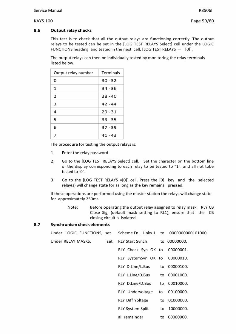
Service Manual R8506I
KAYS 100 Page 59/80
8.6 Output relay checks
This test is to check that all the output relays are functioning correctly. The output relays to be tested can be set in the [LOG TEST RELAYS Select] cell under the LOGIC FUNCTIONS heading and tested in the next cell, [LOG TEST RELAYS = [0]].
The output relays can then be individually tested by monitoring the relay terminals listed below.
Output relay number Terminals
0 30 - 32
1 34 - 36
2 38 - 40
3 42 - 44
4 29 - 31
5 33 - 35
6 37 - 39
7 41 - 43
The procedure for testing the output relays is:
1. Enter the relay password
2. Go to the [LOG TEST RELAYS Select] cell. Set the character on the bottom line of the display corresponding to each relay to be tested to "1", and all not tobe tested to "0".
3. Go to the [LOG TEST RELAYS =[0]] cell. Press the [0] key and the selected relay(s) will change state for as long as the key remains pressed.
If these operations are performed using the master station the relays will change state for approximately 250ms.
Note: Before operating the output relay assigned to relay mask RLY CB Close Sig, (default mask setting to RL1), ensure that the CB closing circuit is isolated.
8.7 Synchronism check elements
Under LOGIC FUNCTIONS, set Scheme Fn. Links 1 to 0000000000101000.
Under RELAY MASKS, set RLY Start Synch to 00000000.
RLY Check Syn OK to 00000001.
RLY SystemSyn OK to 00000010.
RLY D.Line/L.Bus to 00000100.
RLY L.Line/D.Bus to 00001000.
RLY D.Line/D.Bus to 00010000.
RLY Undervoltage to 00100000.
RLY Diff Yoltage to 01000000.
RLY System Split to 10000000.
all remainder to 00000000.

R8506I Service Manual
Page 60/80 KAYS 100
Monitor output relays as instructed for the following tests.
Note that the relay password must be entered for every change of CSS Fn. Links settings.
8.7.1 Phase angle check - instantaneous operation. (Monitor RL0, terminals 30-32).
Under CHECK SYNCH STGS, set CSS Fn. Links to 0000000000000001.
Inject nominal voltage into Y Line terminals 17-18 and Y Bus terminals 19-20, starting with the phase angle between them less than (CSS Phase Angle setting -3°). Output RL0 should operate.
Slowly increase the phase angle until RL0 resets and note the angle when this happens. This should be less than (CSS Phase Angle setting +1°).
Slowly decrease the phase angle until RL0 re-operates and note the angle when this happens. This should be greater than (CSS Phase Angle setting -3°).
8.7.2 Phase angle check - delay on operation. (Monitor RL0, terminals 30-32).
Under CHECK SYNCH STGS, change CSS Fn. Links to 0000000000000101.
Set the phase angle between Y Line and Y Bus inputs greater than CSS Phase Angle setting, so that output RL0 is reset. Switch the phase angle to zero and measure the time for output RL0 to operate. This should be not less than (CSS Synch Timer setting -5% +0.01s) and not greater than (CSS Synch Timer setting +5% +0.04s).
8.7.3 Phase angle check - undervoltage blocking. (Monitor RL0, terminals 30-32, and RL5, terminals 33-35).
Under CHECK SYNCH STGS, change CSS Fn. Links to 0000100000000001.
Set both voltages to greater than CSS Undervoltage setting and phase angle to zero. Out put RL0 should be operated and RL5 reset.
Slowly reduce Y Line until RL0 resets and RL5 operates and note the value when this happens. This should be within + or -5% of CSS Undervoltage setting.
Slowly increase Y Line until RL0 re-operates and RL5 resets and note the value when this happens. This should be within -0% and +10% of the "reset" value.
Slowly reduce Y Bus until RL0 resets and RL5 re-operates and note the value when this happens. This should be within + or -5% of CSS Undervoltage setting.
Slowly increase Y Bus until RL0 re-operates and RL5 resets and note the value when this happens. This should be within -0% and +10% of the "reset" value.
8.7.4 Phase angle check - differential voltage blocking. (Monitor RL0, terminals 30-32, and RL6, terminals 37-39).
Under CHECK SYNCH STGS, change CSS Fn. Links to 0010000000000001.
Set both voltages to nominal and phase angle to zero. Out put RL0 should be operated and RL6 reset.
Slowly reduce Y Line until RL0 resets and RL6 operates and note the (Y Bus - Y Line) value when this happens. This should be within -0Y and +2Y of CSS Diff Yoltage setting.
Slowly increase Y Line until RL0 re-operates and RL6 resets and note the Y Line value when this happens. This should be within -0% and +10% of the Y Line value when RL0 reset in the last test.

Service Manual R8506I
KAYS 100 Page 61/80
Continue slowly increasing Y Line until RL0 resets and RL6 re-operates and note the (Y Line - Y Bus) value when this happens. This should be within -0Y and +2Y of CSS Diff Yoltage setting.
Slowly reduce Y Line until RL0 re-operates and RL6 resets and note the Y Line value when this happens. This should be within -10% and +0% of the Y Line value when RL0 reset in the last test.
Slowly reduce Y Bus until RL0 resets and RL6 re-operates and note the (Y Line - Y Bus) value when this happens. This should be within -0Y and +2Y of CSS Diff Yoltage setting.
Slowly increase Y Bus until RL0 re-operates and RL6 resets and note the Y Bus value when this happens. This should be within -0% and +10% of the Y Bus value when RL0 reset in the last test.
Continue slowly increasing Y Bus until RL0 resets and RL6 re-operates and note the (Y Bus - Y Line) value when this happens. This should be within -0Y and +2Y of CSS Diff Yoltage setting.
Slowly reduce Y Bus until RL0 re-operates and RL6 resets and note the Y Bus value when this happens. This should be within -10% and +0% of the Y Bus value when RL0 reset in the last test.
8.7.5 System angle check - instantaneous operation. (Monitor RL1, terminals 34-36).
Connect relay terminal 7 (field supply +) to terminal 46 (opto input L0).
Under CHECK SYNCH STGS, set CSS Fn. Links to 0000000000100000.
Inject nominal voltage into Y Line terminals 17-18 and Y Bus terminals 19-20, starting with the phase angle between them less than (CSS System Angle setting - 3°). Output RL1 should operate.
Slowly increase the phase angle until RL1 resets and note the angle when this happens. This should be less than (CSS System Angle setting +1°).
Slowly decrease the phase angle until RL1 re-operates and note the angle when this happens. This should be greater than (CSS System Angle setting -3°).
8.7.6 System angle check - delay on operation. (Monitor RL1, terminals 34-36).
Under CHECK SYNCH STGS, change CSS Fn. Links to 0000000010100000.
Set the phase angle between Y Line and Y Bus inputs greater than CSS System Angle setting, so that output RL1 is reset. Switch the phase angle to zero and measure the time for output RL1 to operate. This should be not less than (CSS System Timer setting -5% +0.01s) and not greater than (CSS System Timer setting +5% + 0.04s).
8.7.7 System angle check - undervoltage blocking. (Monitor RL1, terminals 34-36, and RL5, terminals 33-35).
Under CHECK SYNCH STGS, change CSS Fn. Links to 0000100000100000.
Set both voltages to greater than CSS Undervoltage setting and phase angle to zero. Output RL1 should be operated and RL5 reset.
Slowly reduce Y Line until RL1 resets and RL5 operates and note the value when this happens. This should be within + or -5% of CSS Undervoltage setting.
Slowly increase Y Line until RL1 re-operates and RL5 resets and note the value when this happens. This should be within -0% and +10% of the "reset" value.

R8506I Service Manual
Page 62/80 KAYS 100
Slowly reduce Y Bus until RL1 resets and RL5 re-operates and note the value when this happens. This should be within + or -5% of CSS Undervoltage setting.
Slowly increase Y Bus until RL1 re-operates and RL5 resets and note the value when this happens. This should be within -0% and +10% of the "reset" value.
8.7.8 System angle check - differential voltage blocking. (Monitor RL1, terminals 34-36, and RL6, terminals 37-39).
Under CHECK SYNCH STGS, change CSS Fn. Links to 0010000000100000.
Set both voltages to nominal and phase angle to zero. Out put RL1 should be operated and RL6 reset.
Slowly reduce Y Line until RL1 resets and RL6 operates and note the (Y Bus - Y Line) value when this happens. This should be within -0Y and +2Y of CSS Diff Yoltage setting.
Slowly increase Y Line until RL1 re-operates and RL6 resets and note the Y Line value when this happens. This should be within -0% and +10% of the Y Line value when RL1 reset in the last test.
Continue slowly increasing Y Line until RL1 resets and RL6 re-operates and note the (Y Line - Y Bus) value when this happens. This should be within -0Y and +2Y of CSS Diff Yoltage setting.
Slowly reduce Y Line until RL1 re-operates and RL6 resets and note the Y Line value when this happens. This should be within -10% and +0% of the Y Line value when RL1 reset in the last test.
Slowly reduce Y Bus until RL1 resets and RL6 re-operates and note the (Y Line - Y Bus) value when this happens. This should be within -0Y and +2Y of CSS Diff Yoltage setting.
Slowly increase Y Bus until RL1 re-operates and RL6 resets and note the Y Bus value when this happens. This should be within -0% and +10% of the Y Bus value when RL1 reset in the last test.
Continue slowly increasing Y Bus until RL1 resets and RL6 re-operates and note the (Y Bus - Y Line) value when this happens. This should be within -0Y and +2Y of CSS Diff Yoltage setting.
Slowly reduce Y Bus until RL1 re-operates and RL6 resets and note the Y Bus value when this happens. This should be within -10% and +0% of the Y Bus value when RL1 reset in the last test.
8.8 Voltage monitor elements.
Under CHECK SYNCH STGS, change CSS Fn. Links to 0000011100000000.
8.8.1 Dead line/live bus monitor.
Adjust Y Line and Y Bus values and check that output RL2 operates and resets in line with the following table:
V Line value V Bus value RL2 state
CSS Y. B/L Dead - 2Y CSS Y. L/B Live + 2Y Operated
CSS Y. B/L Dead + 2Y CSS Y. L/B Live + 2Y Reset
CSS Y. B/L Dead - 2Y CSS Y. L/B Live - 2Y Reset

Service Manual R8506I
KAYS 100 Page 63/80
8.8.2 Live line/dead bus monitor.
Adjust Y Line and Y Bus values and check that output RL3 operates and resets in line with the following table:
V Line value V Bus value RL3 state
CSS Y. B/L Live + 2Y CSS Y. L/B Dead - 2Y Operated
CSS Y. B/L Live + 2Y CSS Y. L/B Dead + 2Y Reset
CSS Y. B/L Live - 2Y CSS Y. L/B Dead - 2Y Reset
8.8.3 Dead line/dead bus monitor.
Adjust Y Line and Y Bus values and check that output RL4 operates and resets in line with the following table:
V Line value V Bus value RL4 state
CSS Y. B/L Dead - 2Y CSS Y. L/B Dead - 2Y Operated
CSS Y. B/L Dead + 2Y CSS Y. L/B Dead - 2Y Reset
CSS Y. B/L Dead - 2Y CSS Y. L/B Dead + 2Y Reset
8.9 System split detector.
8.9.1 Instantaneous reset. (Monitor RL7, terminals 41-43).
Under CHECK SYNCH STGS, change CSS Fn. Links to 0000000000001000.
Inject nominal voltage into Y Line terminals 17-18 and Y Bus terminals 19-20, starting with the phase angle between them less than (CSS Split Angle setting -3°). Output RL7 should be reset.
Slowly increase the phase angle until RL7 operates and note the angle when this happens. This should be less than (CSS Split Angle setting +3°).
Slowly decrease the phase angle until RL7 resets and note the angle when this happens. This should be greater than (CSS Split Angle setting -3°).
8.9.2 Minimum output pulse. (Monitor RL7, terminals 41-43).
Under CHECK SYNCH STGS, change CSS Fn. Links to 0000000000011000.
Inject nominal voltage into Y Line terminals 17-18 and Y Bus terminals 19-20, starting with the phase angle between them less than (CSS Split Angle setting -3°). Output RL7 should be reset.
Slowly increase the phase angle until RL7 operates then immediately reduce the angle to a value less than (CSS Split Angle setting -3°), and wait for output RL7 to reset. Measure the time for which output RL7 is operated. This should be not less than (CSS Split Timer setting - 5% +0.01s) and not greater than (CSS Split Timer setting +5% +0.04s).
8.10 Final settings
When synchronism check and voltage monitor element checks have been completed, the final "in service" relay settings should be entered. KAYR relays are factory configured with a set of default settings before dispatch. The commissioning engineer should be supplied with a list of all required settings for each relay installation. Any required settings which are different from the default settings, and any settings which were changed for testing (see 8.7 to 8.9 above), may be adjusted
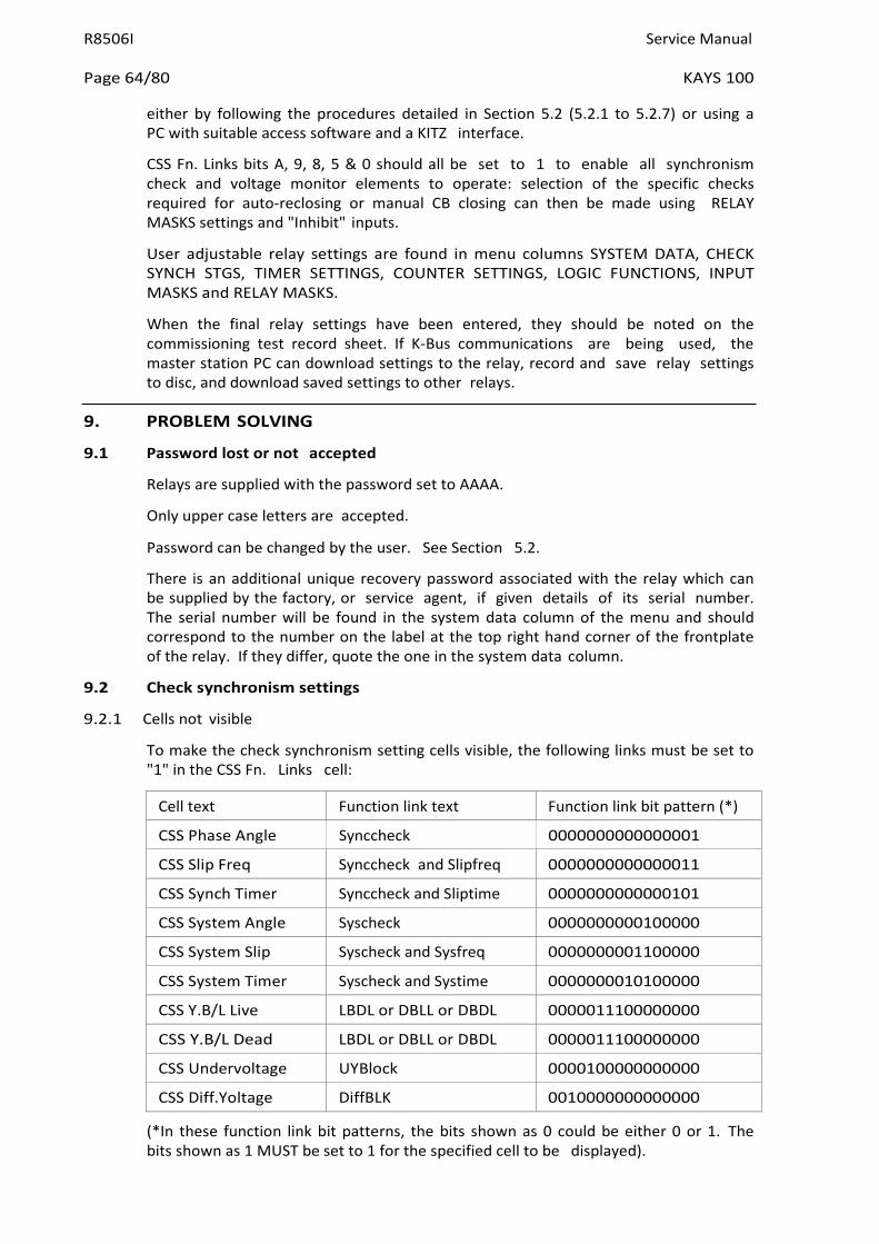
R8506I Service Manual
Page 64/80 KAYS 100
either by following the procedures detailed in Section 5.2 (5.2.1 to 5.2.7) or using a PC with suitable access software and a KITZ interface.
CSS Fn. Links bits A, 9, 8, 5 & 0 should all be set to 1 to enable all synchronism check and voltage monitor elements to operate: selection of the specific checks required for auto-reclosing or manual CB closing can then be made using RELAY MASKS settings and "Inhibit" inputs.
User adjustable relay settings are found in menu columns SYSTEM DATA, CHECK SYNCH STGS, TIMER SETTINGS, COUNTER SETTINGS, LOGIC FUNCTIONS, INPUT MASKS and RELAY MASKS.
When the final relay settings have been entered, they should be noted on the commissioning test record sheet. If K-Bus communications are being used, the master station PC can download settings to the relay, record and save relay settings to disc, and download saved settings to other relays.
9. PROBLEM SOLVING
9.1 Password lost or not accepted
Relays are supplied with the password set to AAAA.
Only upper case letters are accepted.
Password can be changed by the user. See Section 5.2.
There is an additional unique recovery password associated with the relay which can be supplied by the factory, or service agent, if given details of its serial number. The serial number will be found in the system data column of the menu and should correspond to the number on the label at the top right hand corner of the frontplate of the relay. If they differ, quote the one in the system data column.
9.2 Check synchronism settings
9.2.1 Cells not visible
To make the check synchronism setting cells visible, the following links must be set to "1" in the CSS Fn. Links cell:
Cell text Function link text Function link bit pattern (*)
CSS Phase Angle Synccheck 0000000000000001
CSS Slip Freq Synccheck and Slipfreq 0000000000000011
CSS Synch Timer Synccheck and Sliptime 0000000000000101
CSS System Angle Syscheck 0000000000100000
CSS System Slip Syscheck and Sysfreq 0000000001100000
CSS System Timer Syscheck and Systime 0000000010100000
CSS Y.B/L Live LBDL or DBLL or DBDL 0000011100000000
CSS Y.B/L Dead LBDL or DBLL or DBDL 0000011100000000
CSS Undervoltage UYBlock 0000100000000000
CSS Diff.Yoltage DiffBLK 0010000000000000
(*In these function link bit patterns, the bits shown as 0 could be either 0 or 1. The bits shown as 1 MUST be set to 1 for the specified cell to be displayed).

Service Manual R8506I
KAYS 100 Page 65/80
9.2.2 Undervoltage feature does not block
If the undervoltage feature does not block the phase angle or system angle output
Set CSS Fn link UYBlock to "1" (0000100000000000)
9.2.3 Differential voltage feature does not block
If the differential voltage feature does not block the phase angle or system angle output
Set CSS Fn link DiffBLK to "1" (0010000000000000)
9.2.4 Undervoltage feature output has incorrect sense
Set CSS Fn link UYOP to "1" (0001000000000000)
9.2.5 Differential voltage feature output has incorrect sense
Set CSS Fn link DiffOP to "1" (0100000000000000)
9.2.6 Function links cannot be changed
Check that the state of the scheme logic permits changing these menu cells
Enter the password as these menu cells are protected.
Links are not selectable if associated text is not displayed.
9.3 Alarms
If the watchdog relay operates, first check that the relay is energized from the auxiliary supply. If so, then try to determine the cause of the problem by examining the alarm flags towards the bottom of the SYSTEM DATA column of the menu. This will not be possible if the display is not responding to key presses.
Having attempted to determine the cause of the alarm it may be possible to return the relay to an operational state by resetting it. To do this, remove the auxiliary power supply for about 10 seconds. Then re-establish the supplies and the relay should in most cases return to an operating state.
Recheck the alarm status if the alarm LED is still indicating an alarm state. The following notes will give further guidance.
9.3.1 Watchdog alarm
The watchdog relay will pick-up when the relay is operational to indicate a healthy state, with its make contact closed. When an alarm condition that requires some action to be taken is detected the watch-dog relay resets and its break contact will close to give an alarm.
Note: The green LED will usually follow the operation of the watchdog relay in either of the above two cases.
There is no shorting contact across the case terminals connected to the break contact of the watchdog relay. Therefore, the indication for a failed/healthy relay will be cancelled when the relay is removed from its case.
If the relay is still functioning, the actual problem causing the alarm can be found from the alarm records in the SYSTEM DATA column of the menu (see Section 2.16.2).
9.3.2 Unconfigured or uncalibrated alarm
For an UNCONFIGURED alarm the relay logic is stopped and no longer performing its intended function. For an UNCALIBRATED alarm the relay logic will still be

R8506I Service Manual
Page 66/80 KAYS 100
operational but there may be an error in its calibration that may require attention. It may be left running.
To return the relay to a serviceable state the initial factory configuration will have to be reloaded and the relay recalibrated. It is recommended that the work be carried out at the factory, or entrusted to a recognised service centre.
9.3.3 Setting error alarm
A SETTING alarm indicates that the area of non-volatile memory where the selected relay settings are stored, has been corrupted. The current settings should be checked against those applied at the commissioning stage or any later changes that have been made.
If a personal computer (PC) is used during commissioning then it is recommended that the final settings applied to the relay are copied to a floppy disc with the serial number of the relay used as the file name. The setting can then be readily loaded back into the relay if necessary, or to a replacement relay.
9.3.4 "No Service" alarm
This alarm flag can only be observed when the relay is in the calibration or configuration mode when the protection program will be stopped.
9.4 Records
9.4.1 Problems with event records
The event records are erased if the auxiliary supply to the relay is lost for a period exceeding the hold-up time of the internal power supply.
Only limited event data can only be read on the LCD. To obtain full event data the event records must be read via the serial communications port.
The oldest event is overwritten by the next event to be stored when the buffer becomes full.
When a master station has successfully read a record it usually clears it automatically and when all records have been read the event bit in the status byte is set to "0" to indicate that there are no longer any records to be retrieved.
9.5 Communications
Address cannot be automatically allocated if the remote change of setting has been inhibited by function link SD0. This must be first set to "1", alternatively the address must be entered manually via the user interface on the relay.
Address cannot be allocated automatically unless the address is first manually set to 0. This can also be achieved by a global command including the serial number of the relay.
Relay address set to 255, the global address for which no replies are permitted.
9.5.1 Measured values do not change
Yalues in the MEASUREMENTS column are snap shots of the values at the time they were requested. To obtain a value that varies with the measured quantity it should be added to the poll list as described in the communication manual.

Service Manual R8506I
KAYS 100 Page 67/80
9.5.2 Relay no longer responding
Check if other relays that are further along the bus are responding and if so power down the relay for 10 seconds and then re-energise to reset the communication processor. This should not be necessary as the reset operation occurs automatically when the relay detects a loss of communication.
If relays further along the bus are not communicating, check to find out which are responding towards the master station. If some are responding then the position of the break in the bus can be determined by deduction. If none is responding then check for data on the bus or reset the communication port driving the bus with requests.
Check there are not two relays with the same address on the bus.
9.5.3 No response to remote control commands
Check that the relay is not inhibited from responding to remote commands by observing the system data function link settings. If so reset as necessary; a password will be required.
System data function links can not be set over the communication link if the remote change of settings has been inhibited by setting system data function link SD0 to 0. Reset SD0 to 1 manually via the user interface on the relay first.
10. MAINTENANCE
10.1 Testing
K-Series MIDOS relays are self-supervising and so require less maintenance than earlier designs of relay. Most problems will result in an alarm so that remedial action can be taken. However, some periodic tests could be done to ensure that the relay is functioning correctly.
If the relay can be communicated with from a remote point, via its serial port, then some testing can be carried out without actually visiting the site.
When testing locally the same tests may be carried out to check for correct functioning of the relay.
10.1.1 Alarms
The alarm status LED should first be checked to identify if any alarm conditions exist. The alarm records can then be read to identify the nature of any alarm that may exist.
10.1.2 Measurement accuracy
The values measured by the relay can be compared with known system values to check that they are in the approximate range that is expected. If they are, then the A/D conversion and calculations are being performed correctly.
10.1.3 Output relay test
The output relays can be made to change state, if the password has been entered and the Block Output Test software relay is off, using menu cells LOG TEST RELAYS Select (0A07) and LOG TEST RELAYS = [0] (0A08).
The LOG TEST RELAYS Select cell displays the relays to be tested. Setting any position to "1" will result in the state of the corresponding relay changing state when the [0] key is given a long press in cell LOG TEST RELAYS = [0]. The state will remain changed for 250 milliseconds or until the [0] key is released, whichever is longer.
R8506I Service Manual
Page 68/80 KAYS 100
10.2 Additional tests
Additional tests can be selected from the commissioning instructions, Section 8, as required.
10.3 Method of repair
Please read the handling instructions in Section 1 before proceeding with this work. This will ensure that no further damage is caused by incorrect handling of the electronic components.
10.3.1 Replacing a PCB
a) Replacement of user interface
Withdraw the module from its case.
Remove the four screws that are placed one at each corner of the frontplate.
Remove the frontplate.
Lever the top edge of the user interface board forwards to unclip it from its mounting.
Then pull the PCB upwards to unplug it from the connector at its lower edge.
Replace with a new interface board and assemble in the reverse order.
b) Replacement of main processor board
This is the PCB at the extreme left of the module, when viewed from the front. To replace this board:
First remove the screws holding the side screen in place. There are two screws through the top plate of the module and two more through the base plate.
Remove screen to expose the PCB.
Remove the two retaining screws, one at the top edge and the other directly below it on the lower edge of the PCB.
Separate the PCB from the sockets at the front edge of the board. Note that they are a tight fit and will require levering apart, taking care to ease the connectors apart gradually so as not to crack the front PCB card. The connectors are designed for ease of assembly in manufacture and not for continual disassembly of the unit.
Reassemble in the reverse of this sequence, making sure that the screen plate is replaced with all four screws securing it.
c) Replacement of auxiliary expansion board
This is the second board in from the left hand side of the module.
Remove the processor board as described above in b).
Remove the two securing screws that hold the auxiliary expansion board in place.
Unplug the PCB from the front bus as described for the processor board and withdraw.
Replace in the reverse of this sequence, making sure that the screen plate is replaced with all four screws securing it.

Service Manual R8506I
KAYS 100 Page 69/80
10.3.2 Replacing output relays and opto-isolators
PCBs are removed as described in 10.3.1 b and c. They are replaced in the reverse order. Calibration is not usually required when a PCB is replaced unless either of the two boards that plug directly on to the left hand terminal block is replaced, as these directly affect the calibration.
Note: This CB is a through hole plated board and care must be taken not to damage it when removing a relay for replacement, otherwise solder may not flow through the hole and make a good connection to the tracks on the component side of the PCB.
10.3.3 Replacing the power supply board
Remove the two screws securing the right hand terminal block to the top plate of the module.
Remove the two screws securing the right hand terminal block to the bottom plate of the module.
Unplug the back plane from the power supply PCB.
Remove the securing screw at the top and bottom of the power supply board.
Withdraw the power supply board from the rear, unplugging it from the front bus.
Reassemble in the reverse of this sequence.
10.3.4 Replacing the back plane (size 4 & 6 case)
Remove the two screws securing the right hand terminal block to the top plate of the module.
Remove the two screws securing the right hand terminal block to the bottom plate of the module.
Unplug the back plane from the power supply PCB.
Twist outwards and around to the side of the module.
Replace the PCB and terminal block assembly.
Reassemble in the reverse of this sequence.
10.4 Recalibration
Whilst recalibration is not usually necessary it is possible to carry it out on site, but it requires test equipment with suitable accuracy and a special calibration program to run on a PC. It is recommended that the work is carried out by an authorised agency.
After calibration it will be necessary to re-enter all the settings required for the application so it will be useful to have a copy of the settings available on a floppy disk. Although this is not essential it can reduce the down time of the system.
10.5 Return to factory
Should the need arise for the equipment to be returned to General Electric please visit the following web page
www.gegridsolutions.com/contact
A copy of any commissioning test results should also be sent with the equipment.
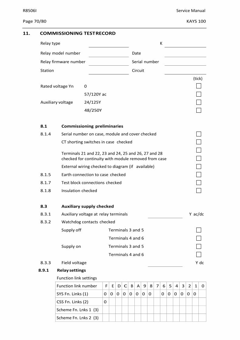
R8506I Service Manual
Page 70/80 KAYS 100
11. COMMISSIONING TEST RECORD
Relay type K
Relay model number Date
Relay firmware number Serial number
Station Circuit
Rated voltage Yn 0
57/120Y ac
Auxiliary voltage 24/125Y
48/250Y
(tick)
8.1 Commissioning preliminaries
8.1.4 Serial number on case, module and cover checked
CT shorting switches in case checked
Terminals 21 and 22, 23 and 24, 25 and 26, 27 and 28 checked for continuity with module removed from case
External wiring checked to diagram (if available)
8.1.5 Earth connection to case checked
8.1.7 Test block connections checked
8.1.8 Insulation checked
8.3 Auxiliary supply checked
8.3.1 Auxiliary voltage at relay terminals Y ac/dc
8.3.2 Watchdog contacts checked
Supply off Terminals 3 and 5
Terminals 4 and 6
Supply on Terminals 3 and 5
Terminals 4 and 6
8.3.3 Field voltage Y dc
8.9.1 Relay settings
Function link settings
Function link number F E D C B A 9 8 7 6 5 4 3 2 1 0
SYS Fn. Links (1) 0 0 0 0 0 0 0 0 0 0 0 0 0 0
CSS Fn. Links (2) 0
Scheme Fn. Lnks 1 (3)
Scheme Fn. Lnks 2 (3)

Service Manual R8506I
KAYS 100 Page 71/80
Notes: 1. System data column
2. Check synch settings column
3. Logic functions column
Input mask settings - KAYS 100
Opto input number
INP Start ChSyn
INP Start SysSyn
INP Inh DLLB/ChS
INP Inh LLDB/ChS
INP Inh DLDB/ChS
INP Inh DLLB/ChS
INP Inh LLDB/SyS
INP Inh DLDB/SyS
INP Inh SysSplit
Relay mask settings - KAYS 100
Relay number
RLY Start Synch
RLY Check Syn OK
RLY SystemSyn OK
RLY D.Line/L.Bus
RLY L.Line/D.Bus
RLY D.Line/D.Bus
RLY Undervoltage
RLY Diff Yoltage
RLY System Split
RLY DLLB/ChSyn
RLY LLDB/ChSyn
RLY DLDB/ChSyn
RLY DLLB/SysSyn
RLY LLDB/SysSyn
RLY DLDB/SysSyn
7 6 5 4 3 2 1 0
7 6 5 4 3 2 1 0
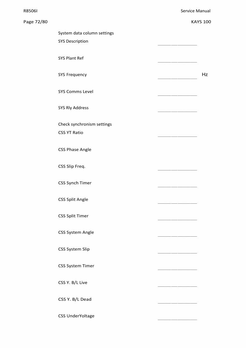
R8506I Service Manual
Page 72/80 KAYS 100
System data column settings
SYS Description
SYS Plant Ref
SYS Frequency Hz
SYS Comms Level
SYS Rly Address
Check synchronism settings
CSS YT Ratio
CSS Phase Angle
CSS Slip Freq.
CSS Synch Timer
CSS Split Angle
CSS Split Timer
CSS System Angle
CSS System Slip
CSS System Timer
CSS Y. B/L Live
CSS Y. B/L Dead
CSS UnderYoltage

Service Manual R8506I
KAYS 100 Page 73/80
CSS Diff.Yoltage
8.4 Metering Checks
Actual Yalue Injected Relay Metered Yalue
Line Yoltage Y Y
Bus Yoltage Y Y
8.5 Opto input checks
Opto input number (tick)
L0
L1
L2
L3
L4
L5
L6
L7
8.6 Output relay checks
Output relay number (tick)
0
1
2
3
4
5
6
7
8.7.1 &
8.7.5 Phase angle element and system angle element
Phase Angle System Angle
Drop Off ° °
Pick Up ° °
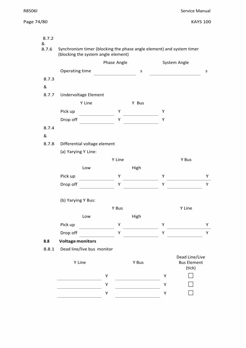
R8506I Service Manual
Page 74/80 KAYS 100
8.7.2 & 8.7.6 Synchronism timer (blocking the phase angle element) and system timer
(blocking the system angle element)
Phase Angle System Angle
Operating time s s
8.7.3
&
8.7.7 Undervoltage Element
Y Line Y Bus
Pick up Y Y
Drop off Y Y
8.7.4
&
8.7.8 Differential voltage element
(a) Yarying Y Line:
Y Line Y Bus
Low High
Pick up Y Y Y
Drop off Y Y Y
(b) Yarying Y Bus:
Y Bus Y Line
Low High
Pick up Y Y Y
Drop off Y Y Y
8.8 Voltage monitors
8.8.1 Dead line/live bus monitor
Y Line Y Bus
Y Y
Y Y
Y Y
Dead Line/Live Bus Element
(tick)

Service Manual R8506I
KAYS 100 Page 75/80
8.8.2 Live line/dead bus monitor
Y Line Y Bus
Y Y
Y Y
Y Y
Live Line/Dead Bus Element
(tick)
8.8.3 Dead line/dead bus monitor
Y Line Y Bus
Y Y
Y Y
Y Y
Dead Line/Dead Bus Element
(tick)
8.9.1 System split element
Phase Angle
Drop Off s
Pick Up s
8.9.2 Split timer
Split time s
Commissioning Engineer Customer Witness
Date Date

R8506I Service Manual
Page 76/80 KAYS 100
12. KAVS100 SOFTWARE HISTORY
KAVS10001x1xJEA -> xJEB (April 1993 to Feb 1994)
4. Original issue functional software.
5. Operating system upgrade to 1.02 - minor bug fix of op system software
6. Operating system upgrade to 1.04 - minor bug fix of op system software
Issue Date SYS Software Ref SYS Ladder Ref
April 1993 Op Sys 1.01 KAYS100EA C1.2
May 1993 Op Sys 1.02 KAYS100EB C1.2
June 1993 Op Sys 1.04 KAYS100EC C1.2
Settings file issue A
KAVS10001x1xJEB -> xJEC (Feb 1994 to August 1994)
1. Operating system upgrade to 1.05 - minor bug fix of op system software
2. Operating system upgrade to 1.1 - Yline and Ybus option added to default display, En Log Evts function link added, set alarm condition added to generate an event when an alarm occurs
Issue Date SYS Software Ref SYS Ladder Ref
Jan 1994 Op Sys 1.05 KAYS100ED C1.2
March 1994 Op Sys 1.1 KAYS100EE C1.3
Settings file issue A for KAYS100ED C1.2 and B for KAYS100EE C1.2
KAVS10001x1xJEC -> xJED (Feb 1994 to Nov 1997)
1. Operating system upgrade to issue 1.12 - reset alarm condition added
2. Operating system upgrade to issue 1.21 - Reset Alarms cell made available in default display
3. Operating system upgrade to issue 1.3 - minor bug fix of op system software
4. Operating system upgrade to issue 1.31 - test watchdog feature added
5. Operating system upgrade to issue 1.34 - minor bug fix of op system software
6. Operating system upgrade to issue 1.41 - minor bug fix of op system software
Issue Date SYS Software Ref SYS Ladder Ref
August 1994 Op Sys 1.12 KAYS100EF C1.41
Dec 1994 Op Sys 1.21 KAYS100EG C1.43
March 1995 Op Sys 1.3 KAYS100EH C1.44
May 1995 Op Sys 1.31 KAYS100EI C1.45

Service Manual R8506I
KAYS 100 Page 77/80
Issue Date SYS Software Ref SYS Ladder Ref
Nov 1995 Op Sys 1.34 KAYS100EJ C1.46
November 1997 Op Sys 1.41 KAYS100EM C1.51
Settings file issue C.
There was a retrospective update of opsys in Nov 1997 for KAYS10001D1xJEC
KAVS10001x1xJED -> xJEE (Nov 1995 to Dec 1996)
1. Operating system upgrade to issue 2.02 - Opsys for new 20Mhz processor, previously 16Mhz
Issue Date SYS Software Ref SYS Ladder Ref
Nov 1995 Op Sys 2.02 KAYS100EJ C1.46
Settings file issue C.
KAVS10001x1xJEE -> xJEF (Dec 1996 to March 1997)
1. Increase Synch Window max time to 9999s, Blockins seal in during protection operation, pulsed CB Fail and Success A/R operation
Issue Date SYS Software Ref SYS Ladder Ref
Nov 1996 Op Sys 2.10 KAYS100EK C1.50
Settings file issue C.
KAVS10001x1xJEF -> xJEG (March 1997 to Nov 1997)
1. Operating system upgrade to issue 2.11 - minor bug fix of op system software
Issue Date SYS Software Ref SYS Ladder Ref
June 1997 Op Sys 2.11 KAYS100EL C1.51
Settings file issue C.
KAVS10001x1xJEG -> xJEH (Nov 1997 to July 1998)
1. Logic change for 'Global Reset' function operated by simple press of [0] key, selectable undervoltage and differential voltage alarm
Issue Date SYS Software Ref SYS Ladder Ref
Nov 1997 Op Sys 2.20 KAYS100EM C1.60
Settings file issue D.

R8506I Service Manual
Page 78/80 KAYS 100
KAVS10001x1xJEH -> KAVS10001D1xJEJ/K/L (July 1998 to April 2000)
1. Operating system upgrade to issue 2.23 - Change manufacturer ID to AREYA.
Issue Date SYS Software Ref SYS Ladder Ref
Feb 1999 Op Sys 2.23 KAYS100EN C1.63
Settings file issue D.
KAVS10001x1XJEJ/K/L -> KAVS10001D1xJEM (July 1998 to Jan 2001)
1. Operating system upgrade to issue 2.24 - Smoothing of Fourier sampled data. Other changes added in April 2000 are described below , KAYS100 FUNCTIONAL CHANGES - April 2000.
Issue Date SYS Software Ref SYS Ladder Ref
April 2000 Op Sys 2.24 KAYS100EO C1.64
Settings file issue E.
KAVS10001x1XJEM (Jan 2001 to date)
1. Operating system upgrade to issue 2.25 - upper limit for differential voltage changed to 50Y
Issue Date SYS Software Ref SYS Ladder Ref
Jan 2001 Op Sys 2.25 KAYS100EP C1.64
Settings file issue E.
KAVS100 FUNCTIONAL CHANGES - April 2000
Introduction
These notes describe the changes in the KAYS100 relay functional logic, which were included in April 2000.
Input Masks - see section 2.3
Input masks INP Inh CheckSyn and INP Inh Sys Syn have been deleted, and the functionality of input masks INP Start ChSyn and INP Start SysSyn is slightly modified, as described under Revised Logic Functions.
Revised Logic Functions - see section 2.8
The effect of Scheme Fn Links 1 bits 0 and 1 is slightly changed: if bit 0 = 0, input INP Start ChSyn has to be off to enable/on to block phase angle check (output mask RLY Check Syn OK) (default setting); if bit 0 = 1, input INP Start ChSyn has to be on to enable/off to block phase angle check (output mask RLY Check Syn OK); if bit 1 = 0, input INP Start SysSyn has to be off to enable/on to block system angle check (output mask RLY SystemSyn OK) (default setting); if bit 1 = 1, input INP Start SysSyn has to be on to enable/off to block system angle check (output mask RLY SystemSyn OK).

Service Manual R8506I
KAYS 100 Page 79/80
New Logic Functions - see section 2.8.
Five new scheme function links have been added, as described below. The table gives only very brief details; more information is given in section 2.2.6 and 2.2.7.
Logic FNCT number
Scheme Fn. Links 1 bit no.
Display Name
Effect in scheme logic
7 7 Auto Sys Syn 0 = Ph. Angle & Sys. Angle independent (D) 1 = Auto switch following Sys Split
8 8 Split No Hold 0 = System Split blocks Ph Angle & S Angle (D) 1 = Sys Split does not block Ph A & S A
9 9 No Timeout SS 0 = System Sync auto-timeout enabled (D) 1 = System Sync auto-timeout disabled
10 A No Autoreset SS
0 = Sys Sync mode reset when "In Sync" (D) 1 = Sys Sync mode not reset when "In Sync"
11 B No Global Reset
0 = UY, Diff Y & Split alarms can be reset by "Global Reset" (D) 1 = UY, Diff Y & Split alarms cannot be reset by "Global Reset"
12 to 15 C to F Not used. All fixed = 0.
Alarms Resetting - see section 2.11
If new FNCT 11 (No Global Reset) is set to 1, the "Status 1" alarms Undervoltage, Differential Yoltage and System Split, cannot be reset using the [0] key.
Volts Healthy Output
A new output mask 'RLY YLYB Healthy' has been added, which may be assigned to an output relay if required. The output operates if the Undervoltage Alarm and/or Differential Yoltage Alarm is enabled (FNCT 3 = 1 and/or FNCT 5 = 1) BUT neither of the alarms is set.
Recorder Triggers
A Disturbance Recorder facility has been added to the KAYS100 relay, to aid analysis of system disturbances, even though there are no current inputs to the relay. The disturbance recorder is described in sections 2.12, 2.18.2, and 5.3.

Imagination at work
Grid Solutions St Leonards Building Redhill Business Park Stafford, ST16 1WT, UK +44 (0) 1785 250 070 www.gegridsolutions.com/contact
© 2017 General Electric. All rights reserved. Information contained in this document is indicative only. No representation or warranty is given or should be relied on that it is complete or correct or will apply to any particular project. This will depend on the technical and commercial circumstances. It is provided without liability and is subject to change without notice. Reproduction, use or disclosure to third parties, without express written authority, is strictly prohibited.
R8506I